the role of superhydrophobicity in the adhesion of a ...fluids.snu.ac.kr/publication/lifting.pdf ·...
TRANSCRIPT
J. Fluid Mech. (2009), vol. 624, pp. 23–32. c© 2009 Cambridge University Press
doi:10.1017/S002211200900593X Printed in the United Kingdom
23
The role of superhydrophobicity in the adhesionof a floating cylinder
DUCK-GYU LEE AND HO-YOUNG KIM†School of Mechanical and Aerospace Engineering, Seoul National University,
Seoul 151-744, Korea
(Received 19 August 2008 and in revised form 9 January 2009)
Horizontal cylinders floating on liquid surfaces are mundanely observed, whoseexamples include the legs of aquatic arthropods and floating larvae, twigs andhairs. We study the force and energy required to lift the cylinder clear from thewater surface, to evaluate the role of wettability, especially superhydrophobicity, inthe adhesion of floating cylinders. We find that a drastic degree of energy savingis achieved when lifting a superhydrophobic cylinder as compared with a cylinderwith moderate wettability. This can serve as a starting point to understand howthe superhydrophobicity of the legs of water-walking insects help to propel themefficiently.
1. IntroductionTo lift a horizontal cylinder initially floating on a liquid surface, one needs to exert
force in excess of the cylinder’s weight to overcome the adhesion between the solidand the liquid. Also, it is a mundane experience that less wettable solid objects need tobe pulled up a shorter distance than more wettable ones before detachment, implyingthat less work is necessary. Here we aim to quantify the force of the adhesion and theenergy required to lift the cylinder clear from the liquid surface, which are dependenton the solid wettability. Horizontal objects floating on liquid surfaces are commonlyobserved with the examples including hairs, fibres, minerals, twigs, bacteria andlarvae (Hu & Bush 2005) floating on water. An industrial mineral-separation processcalled flotation (Derjaguin & Dukhin 1961) needs understanding of the physics ofdetachment.
Another interesting problem involving detachment of floating cylinders can befound in some insects and spiders. Aquatic arthropods, such as the water strider andthe fishing spider, have such an amazing mobility on water that they float effortlesslyusing only tarsi, skate and even jump on water (Hu, Chan & Bush 2003; Bush & Hu2006). In seeking to understand the relationships between these exceptional functionsand the biological adaptations required to facilitate them, it was found that thesurface of a water strider’s legs is covered with a mat of fine, oriented hairs whichthemselves are covered with nanogrooves. This hierarchical structure explains theobserved superhydrophobicity of the legs, which typically have a contact angle near167◦ (Gao & Jiang 2004; Bush, Hu & Prakash 2008). It has also been observed thata single leg is able to support a load 15 times greater than the weight of the waterstrider without piercing the air–water interface (Gao & Jiang 2004). It was widely
† Email address for correspondence: [email protected]

24 D.-G. Lee and H.-Y. Kim
assumed that this striking load-bearing capacity is due to the superhydrophobicityof the strider’s legs. However, recent experimental and theoretical studies (Vella, Lee& Kim 2006; Liu, Feng & Wang 2007; Song & Sitti 2007) have revealed that lesshydrophobic (having contact angle near 90◦) cylindrical rods are able to supportsimilar maximum loads to superhydrophobic cylinders of the same dimensions. Thisis particularly the case for rods with small diameter (water strider legs typically havediameter 100 μm), suggesting that the superhydrophobicity of these legs can only havea limited influence on the insect’s static stability at the interface.
The relative insensitivity of the leg’s static load-supporting capability to the preciselevel of its hydrophobicity suggests that the water-repellent hairy surface of a waterstrider may instead play an important role in dynamic situations. Superhydrophobicsurfaces immersed in liquid have been reported to experience less drag (Choi &Kim 2006); thus this mechanism may reduce the water resistance when the stridersskate on water (Shi et al. 2007; Bush et al. 2008). The unique properties of thesesurfaces can help a submerged water strider being bombarded by raindrops to quicklyresurface on water (Shi et al. 2007). It was also pointed out that the directionality ofmicrosetae and nanogrooves on the legs may increase the interaction force with waterwhile the strider propels itself (Bush et al. 2008). The effects of the directionality offlow slip that can be invoked by those tiny hairs on the friction force between afluid and a boundary were quantified by Philip (1972), Lauga & Stone (2003) andSbragaglia & Prosperetti (2007). A recent experimental study also showed that tinysuperhydrophobic spheres are able to bounce off the water surface after impact –something that is not observed with less hydrophobic spheres (Lee & Kim 2008). Thisobservation implies that strong water repellency is essential for the strider to be ableto jump on water.
Although several qualitative hypotheses of how superhydrophobicity helps the lifeof aquatic arthropods on water have been suggested as described above, quantitativeexplanations of the role played by their unique water-repellent surfaces can hardlybe found. Considering that a water strider should lift its legs to propel itself, thestudy of the detachment process of a floating cylinder can serve as a starting pointto understand the role of superhydrophobicity in the strider locomotion in additionto the aforementioned practical and mundane implications. In the following, weformulate the theory to calculate the force and energy required to lift a cylinder clearfrom the water surface and experimentally corroborate the results.
2. Theoretical formulation and experiments2.1. Lifting energy
We consider a solid cylinder of radius r0, length L and density ρs being lifted offliquid having density ρw and surface tension γ in a quasi-static manner as shownin figure 1. The work W required to lift the cylinder off the liquid surface can beobtained by integrating the pulling force Fp along the displacement of the centre ofthe cylinder cross-section in the y-direction:
W =
∫ hb
ha
Fpdy, (2.1)
where ha is the position of the centre of the cylinder when floating in equilibrium(i.e. when Fp = 0) and hb is the elevation of the cylinder corresponding to the completedetachment of the liquid meniscus. The force balance states that Fp should be equal

The role of superhydrophobicity in the adhesion of a floating cylinder 25
y
x
–φ z
h∗
Air ρa
Water ρw
h
g
h0
r0
θr
Fp
Fpρs
β
(a) (b)
Figure 1. Images and schematics of a cylinder being lifted vertically off the liquid surface. (a)The view along the axis of the cylinder. (b) The view perpendicular to the axis of the cylinder.The radius, the length and the receding contact angle of the cylinder are 0.23mm, 39.9 mmand 50◦, respectively.
to the sum of the solid weight Fw , the buoyancy Fb, the surface tension force alongthe cylinder side Fs and the surface tension force at the ends of the cylinder Fe:
Fp = Fw + Fb + Fs + Fe. (2.2)
The weight of the solid cylinder Fw = πρsr20gL, where g is the gravitational
acceleration. The buoyancy Fb = ρwgΩ1, where Ω1 is the volume of liquid boundedby the wetted surface of the cylinder side, a vertical plane through the three-phase line and the undisturbed horizontal free surface (Keller 1998). Thus we getΩ1 = r2
0L(2h∗ sinβ/r0 −β +sinβ cos β), where h∗ is the elevation of the contact line onthe cylinder side and β is the angular position of the contact line as shown in figure 1.The surface tension force along the side Fs = −2γL sinφ, where φ is the slope of thetangent of the meniscus at the cylinder side. The force at the ends of the cylinderFe is equivalent to the weight of the liquid lifted by the cylinder ends (Keller 1998);thus Fe = 2ρwgΩ2, where Ω2 is the liquid volume obtained by integrating h as shownin figure 1(b) over the area on the original horizontal free surface Ab: Ω2 =
∫Ab
hdAb.For a very long cylinder in which the end effects can be neglected, Fs � Fe; thenthe problem reduces to a two-dimensional one, which was treated for a case Fp =0previously (Vella et al. 2006). For cylinders with finite length in which Fe is no longernegligible as compared with Fb, the three-dimensional Young–Laplace equation (Fenget al. 2007) should be solved:
ρwg
γh =
(1 + h2
x
)hzz − 2hxhzhxz +
(1 + h2
z
)hxx(
1 + h2x + h2
z
)3/2. (2.3)
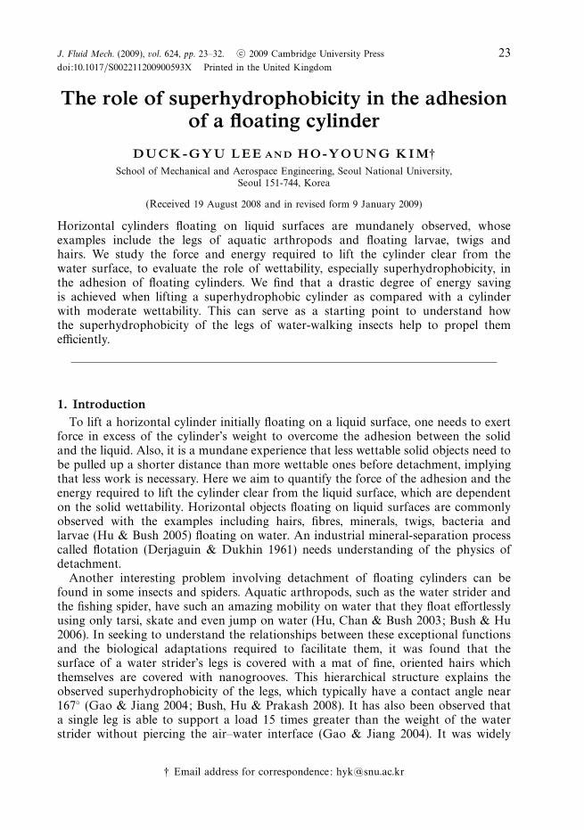
We employ a finite-difference method to numerically solve and integrate (2.3) over thearea and determine Fe. Here we note that Fe accounts for the weight of liquid pulledalong with the liquid lifted by the cylinder side near the end as shown in figure 2which is the computed profile of the meniscus adjoining the cylinder end. Thus Fe isnot simply scaled as γ r0 but rather is significantly greater than that.
26 D.-G. Lee and H.-Y. Kim
04
812
16
04
812
16
0.02
0.04
0.06
z (mm)
x (mm)
y (m
m)
Figure 2. The profile of the meniscus adjoining an end of a cylinder with the radius 50 μm andθr = 160◦ whose centre is lifted 0.0997 mm above the free surface (xz -plane). The cylinder axisis parallel to the z -axis, and its end faces the xy-plane. The three-dimensional Young–Laplaceequation was solved assuming that h at z = 0 is given by the two-dimensional Young–Laplaceequation solved for the cylinder side. Only half the elevated surface (positive x ) is shown forclarity.
2.2. Detachment condition
In integrating Fp in y, it is necessary to find ha and hb, corresponding to the initialand end positions of the cylinder-lifting process, respectively. The initial equilibriumposition ha is obtained straightforwardly by solving (2.2) with Fp = 0. A condition forthe liquid meniscus to detach from the solid cylinder is needed to predict hb, whichis elaborated on in the following: As the cylinder is lifted, the menisci touching thecylinder side approach each other, moving on the lower side of the cylinder. Althoughit is possible to theoretically calculate the meniscus profile until the two meniscieventually meet, our experiments (described below) reveal that the detachment ofthe liquid menisci occurs well before the menisci intersect. Thus, we employ a freeenergy analysis to find the detachment condition of the liquid meniscus from thesolid surface. Rapacchietta, Neumann & Omenyi (1977) calculated the free energydifferences at various positions of a two-dimensional, infinitely long cylinder with thereference state being the one in which the cylinder is separated from the fluid interface.We predict the detaching height hb using the condition that upon detachment thedifference of the free energy E from that of the reference detached state (Er ) vanishes:�E = E−Er = 0. Further elevation of the cylinder without meniscus detachment leadsto a higher energy state than the reference state; thus small perturbations to the systemcause the meniscus to be detached. Figure 3 illustrates the schematic meniscus profileand �E versus β .
Lifting a cylinder keeping contact with the liquid menisci causes the free energychange of liquid associated with the changes of the interfacial areas of the liquidwith the solid (�E1) and with the air (�E2) and the changes of the gravitationalpotential energy of the liquid (�E3). In principle, the surface being hysteretic, thedefinition of free energy associated with the change of the liquid–solid interfacialarea is ambiguous. However, as the motion never changes sign, the contact angle islocked to the receding value, and we can here define an effective free surface energydifference �E1 as
�E1 = −2β cos θr − 2r0
Lcos θr (β − sinβ cosβ), (2.4)

The role of superhydrophobicity in the adhesion of a floating cylinder 27
0
Solid-liquidseparation
Unstableequilibrium
Stableequilibrium
β
ΔE
Figure 3. The schematic of a free energy diagram for a floating cylinder.
where the dimensionless energy E = E/Lr0γ and θr is the receding contact angle.The first and second terms of the right-hand side of (2.4) correspond to the energydifferences due to the change of the interfacial area on the cylinder side and on thecylinder ends, respectively. Here we write the free energy difference per unit area�e = γSG − γSL = γ cos θr , where γSG and γSL are the interfacial energy per unit areabetween solid and gas and that between solid and liquid, respectively, because of thefollowing reason: As the force exchanged between the solid and the free surface isalways equal to γ cos θr , �e is exactly equal to this value (principle of virtual works).An alternative justification can also be provided in the framework of some specificmodels of wetting, for instance those proposed by Blake & Haynes (1969) and deRuijter, Blake & De Coninck (1999). In this framework, �e consists of the differenceof the equilibrium interfacial energies per unit area, γ cos θe via Young’s equation, andthe work q done by the force causing the contact line to move per unit displacementof unit length. Here θe is the equilibrium contact angle. They suggested a microscopicmodel in which the movement of the contact line can be viewed as the motion offluid molecules to the neighbouring adsorption site on a solid. The jumping of fluidmolecules between the adsorption sites is caused by the out-of-balance surface tensionacting on the contact line; thus the work q is written as q = γ (cos θr − cos θe). Thenwe get �e = γ cos θr .
The change of the air–water interfacial area causes the free energy difference �E2:
�E2 =2√
2
Bo1/2
{√2 − [1 − cos(θr + β)]1/2
}− 2 sinβ + 2
Ai − Ab
r0L, (2.5)
where the Bond number Bo = ρwgr20/γ and Ai is the interfacial area between the air
and the liquid lifted by a cylinder end. The first two terms of right-hand side of (2.5)are due to the change of the interfacial area of the liquid lifted by the cylinder sidewith the air, and the last term is due to the change of the interfacial area of the liquidlifted by the cylinder end with the air. As the menisci are lifted with the cylinder, thegravitational potential energy of the liquid changes. The work to depress or raise theliquid volume by the cylinder side, represented as the hatched area in figure 4, causesthe free energy difference �E31:
�E31 =2
3
(2
Bo
)1/2 {[1 − cos(θr + β)]1/2 [2 + cos(θr + β)] −
√2}
. (2.6)
The free energy change associated with the work to raise or depress the liquidunderneath the cylinder, whose volume corresponds to the grey area in figure 4, is

28 D.-G. Lee and H.-Y. Kim
ΔE32 ΔE31ΔE32 ΔE31
α
(a) (b)
Figure 4. The view along the axis of the cylinder for the liquid elevated or depressed by thecylinder (a) for |h0| � r0 and (b) for |h0| > r0.
given by
�E32 = Bo
[cos2 α sin β −
(β +
1
2sin 2β
)cos α + sinβ − 1
3sin3 β
](2.7)
for |h0| � r0 and
�E32 = Bo
[(h∗
r0
)2
sinβ +
(1 − 1
3sin2 β
)sinβ − β cos β − h∗
r0
(β − sinβ cos β)
]
(2.8)
for |h0| > r0, where α is the angular position at which the extended undeformed free
surface intersects the cylinder. The last contribution to �E3 comes from the work toraise or depress the volume of the liquid around the cylinder ends:
�E33 =Bo
Lr30
∫Ab
h2 dAb. (2.9)
Thus the total free energy associated with the work to lift the liquid weight�E3 = �E31 + �E32 + �E33.
2.3. Experiments
Before discussing the results of the theoretical work to lift cylinders, we describethe experiments performed to corroborate our theory. Starting from the equilibriumposition with Fp =0, which is a stable equilibrium in which the total free energy
change, �E = �E1 +�E2 +�E3, is negative, we gradually lift the cylinder to find Fp
as a function of h0. When the theoretically calculated �E reaches zero, the cylinderis assumed to be completely detached from the liquid surface. To verify our theory,we measured the force required to lift a floating thin cylinder off the water surface asa function of the cylinder location. In the experiments, the stainless steel wires withr0 = 400 μm, L =4 cm and ρs = 8000 kgm−3 were coated with three different materialsto vary the solid’s wettability. By spray-coating the wire with a nitrocellulose lacquer(NL), we obtained the receding contact angle of θr = 50◦. By dip-coating the wire withparaffin wax (PW), we obtained θr =96◦. Superhydrophobic wires were fabricated byspray-coating the wire with a mixture of melted alkyl ketene dimer (AKD) andchloroform, which resulted in θr = 148◦ (Torkkeli et al. 2001). The receding contactangles were measured by pulling planar sheets coated with each material out of waterwith the same speed as used in the main experiments (10 μms−1). The images of themenisci were taken from the side with a camera of 512 × 512 pixels. The range of error

The role of superhydrophobicity in the adhesion of a floating cylinder 29
0
0.8
1.6
2.4
3.2
4.0
–0.2 0.2 0.6 1.0 1.4 1.8
h0 (mm)
I
II
III
(a) (b)
0
0.3
0.6
0.9
1.2I
II
III
I
II
III
II
III
I
–0.5 0 0.5 1.0 1.5 2.0 2.5 3.5 3.0
h0 (mm)
Fp
(mN
)
Figure 5. Pulling force versus cylinder elevation. (a) Comparison of the theoretical predictions(solid and dashed lines) and the experimental results of Fp as functions of the location of thecylinder centre. The solid lines correspond to the theoretical results considering the weight ofliquid adjoining the cylinder ends (Fe) in (2.2), while the dashed lines correspond to the resultsneglecting the three-dimensional effects caused by Fe . The circles, squares and triangles denotethe measurement results for the wires coated with NL (surface I: θr = 50◦), PW (surface II:θr = 96◦) and AKD (surface III: θr = 148◦), respectively. In the experiments, the force dropssuddenly after reaching the maximum because the meniscus-detaching process ensues. Theinsets show the meniscus profiles corresponding to the moment of detachment for each contactangle condition. (b) Comparison of theoretical pulling forces for the cylinders (solid lines) usedin (a), the spheres with the same surface area (dashed lines) and the spheres with the samevolume (dotted lines) as those of the cylinders.
in the contact angle measurement is ±1◦. To measure the force exerted on a wire incontact with water surface, we used a surface tension meter (Data Physics DCAT21),in which the wire was fixed on a balance located at the top of the apparatus, and thewater vessel moved down at the rate 10 μms−1. The errors associated with readingthe position and the force are within ±0.1 μm and ±0.1 μN, respectively.
3. ResultsThe force measurement results are compared with the theory in figure 5(a). The
theoretical force values considering the liquid weight adjoining the cylinder ends aswell as the cylinder side agree well with the experimental results, while the two-dimensional model excluding the liquid weight surrounding the cylinder ends exhibitsincreasing discrepancy with the experiments with the increase of h0. Furthermore, thetheory predicts the cylinder height, where the liquid menisci are detached from thesolid fairly accurately. On the other hand, a simplistic hypothesis that the cylinder isdetached clear from water when the two hanging menisci intersect each other predictsdetachment heights which are approximately four times greater than those obtainedfrom the free energy analysis above (hb = 5.17mm for an NL cylinder, hb = 3.88 mmfor a PW cylinder and hb = 1.78mm for an AKD cylinder, using the simplisticdetachment hypothesis). We find that the more hydrophobic the cylinder, the smallerthe area below the force curve which corresponds to the work required to lift eachcylinder off the liquid surface. This considerable reduction of lifting energy with theincreased hydrophobicity is caused by the fact that a more hydrophobic cylinderfloats higher initially with a smaller area being wetted (the force curve starting fromhigher h0) and that the liquid menisci are detached from the cylinder earlier (the forcecurve ending at lower h0).
30 D.-G. Lee and H.-Y. Kim
10 40 70 100 130 160
Contact angle (deg.)
0
0.05
0.10
0.15
0.20
Work
(μ
J)
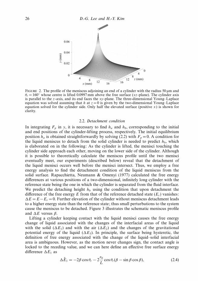
Figure 6. The work required to lift a cylinder having the characteristic dimensions of a waterstrider’s leg, L = 5.5 mm and r0 = 60 μm, for different contact angles. The circles denote thetheoretical results considering the three-dimensional effect due to the meniscus at the cylinderend, and the squares correspond to the two-dimensional results neglecting the cylinder endeffects. Although the two models predict slightly different detachment height, we used the samedetachment height for both the calculations that was from the three-dimensional model.
Figure 5(b) compares the pulling force for the three-dimensional cylinder offigure 5(a) with the forces required to pull the spheres with the same volume andwith the same surface area as those of the cylinder. The force components due tobuoyancy and surface tension and the free energy change associated with the sphere-lifting process are given by Rapacchietta & Neumann (1977). We used the samecriterion for the meniscus detachment, i.e. �E = 0, for the spheres. The forces topull the spheres are shown to be considerably less than that for the cylinders. Thisis primarily due to reduced contact line length of the spheres which determines themagnitude of the surface tension force. The sphere of the same volume as that of acylinder with L � r0 has the radius rV ∼ (r2
0L)1/3. Thus the ratio of the contact linelength of the sphere lV and that of the cylinder lC becomes lV / lC ∼ (r0/L)2/3. For thesphere of the same surface area with the radius rA ∼ (r0L)1/2, the ratio of the contactline length of the sphere lA and lC is lA/ lC ∼ (r0/L)1/2. Figure 5 shows that the spherewith the same volume needs less pulling force than the sphere with the same surfacearea, a tendency consistent with lV / lC < lA/lC .
Our general theory to predict the force and energy to detach a cylinder from thewater surface can be applied to a biologically relevant situation. Considering that thelegs of water striders are superhydrophobic, we compare the energy values required tolift legs having the characteristic dimensions of a leg of a water strider Gerridae (Hu2006), L = 5.5mm and r0 = 60 μm, with varying wettability. Integrating the pullingforce to lift the leg until the menisci are detached for different contact angles leadsto the results as shown in figure 6. The figure shows a dramatic reduction of energywhen the leg becomes hydrophobic: the required work is 1.21 nJ for θr = 160◦, only1.96 % and 5.55 % of the work required for θr = 90◦ and 120◦, respectively. Hu (2006)measured the leaping height of a 4.5 mg heavy water strider to be 5 cm, to find thatthe associated potential energy increase reaches 2.2 μJ, giving a characteristic valueof work per stroke in the strider propulsion. Considering that the strider’s six legsare wet over the perimeter of 22 mm, the values of the energy required to lift thelegs of the same size off water but with the contact angle 10◦ and 90◦ are 0.75 μJ

The role of superhydrophobicity in the adhesion of a floating cylinder 31
(34 % of the characteristic work) and 0.25 μJ (11 % of the characteristic work),respectively. However, when the contact angle increases to 160◦, the lifting energybecomes as small as 4.85 nJ, only 0.22 % of the characteristic work. Although ouranalysis oversimplifies the real motion of the water strider legs as discussed below,the foregoing calculation suggests that the strider with water-repellent legs can avoidwasting energy to overcome the legs’ adhesion with water in a routine life of skatingand jumping.
4. DiscussionThe theory that was developed and experimentally corroborated in this work
enabled us to calculate the work needed to lift horizontal cylinders clear from thewater surface. The superhydrophobicity of the cylinder was shown to dramaticallyreduce the detachment work, and the degree of energy saving was quantified. Inaddition to providing an analytical tool to understand the mundane phenomena ofwet adhesion of floating objects, our work can be employed to understand an industrialmineral-separation process, flotation, and the biological locomotion associated withaquatic arthrodpods with some limitations as discussed below. As the biologicallyinspired robotic technology advances rapidly (Hu et al. 2007), our theory can alsobe applied to predicting the driving power of the robots mimicking the aquaticarthropods that seem to have been evolved to save energy so efficiently.
Although our current theory can be applied to understand a role of thesuperhydrophobicity in the aquatic arthropod locomotion, our focus has been ona quasi-static process of vertical lifting; much remains to be done to further theunderstanding of the role of super-water-repellent hairy structure of the water strider’sleg in more realistic locomotion scenarios. Firstly, dynamic effects associated with themotion of the leg and the surrounding fluid need to be added when the leg moveswith a velocity U that is no longer negligible. Then the force balance should includethe inertia of the leg (∼ρsr
20LU ) and of the surrounding water (∼ρwr2
0LU ), viscousfriction (∼(ρwμr0L
2U 3)1/2) and form drag (∼ρwU 2r0L), where the overdot denotesthe time derivative and μ is the water viscosity. Furthermore, the dynamic meniscusshape no longer follows the Young–Laplace equation and must be calculated bysolving for the full fluid flow problem, as has recently been done for the impact of asmall object onto a liquid surface (Vella & Metcalfe 2007). This dynamic evolutionwill alter the volume and the interfacial area of liquid dragged upward by the risingsolid. Secondly, one needs to consider a case in which a water strider lifts its legsoblique rather than perpendicular to the horizontal, especially when skating. Bushet al. (2008) postulated that the water strider withdraws its leg after the driving strokein such a direction that a peeling of the tilted flexible nanohairs covering the legoccurs. Then the directional wettability of the leg may play an important role. Onealso needs to consider the fact that the water strider leg surface is covered by a seriesof hairs that are inclined relative to the leg, bending so as to lie roughly parallel tothe leg axis. The sum of the detachment force on an individual hair would be thetotal force experienced by a leg, and the smooth cylinder approach as adopted heremay be valid only when the spacing between hairs is sufficiently small.
We thank Dr Dominic Vella for stimulating discussions. This work was supportedby Korea Research Foundation grants (KRF-2006-331-D00068 and KRF-2007-412-J03001) administered via SNU-IAMD.

32 D.-G. Lee and H.-Y. Kim
REFERENCES
Blake, T. D. & Haynes, J. M. 1969 Kinetics of liquid/liquid displacement. J. Colloid Interface Sci.30, 421–423.
Bush, J. W. M. & Hu, D. L. 2006 Walking on water: biolocomotion at the interface. Annu. Rev.Fluid Mech. 38, 339–369.
Bush, J. W. M., Hu, D. L. & Prakash, M. 2008 The integument of water-walking arthropods: formand function. Adv. Insect Physiol. 34, 117–192.
Choi, C.-H. & Kim, C.-J. 2006 Large slip of aqueous liquid flow over a nanoengineeredsuperhydrophobic surface. Phys. Rev. Lett. 96, 066001.
Derjaguin, B. V. & Dukhin, S. S. 1961 Theory of flotation of small and medium size particles.Trans. Inst. Mining Met. 70, 221–246.
Feng, X.-Q., Gao, X., Wu, Z., Jiang, L. & Zheng, Q.-S. 2007 Superior water repellency of waterstrider legs with hierarchical structures: experiments and analysis. Langmuir 23, 4892–4896.
Gao, X. & Jiang, L. 2004 Water-repellent legs of water striders. Nature 432, 36.
Hu, D. L. 2006 The hydrodynamics of water-walking insects and spiders. PhD thesis, MassachusettsInstitute of Technology, Cambridge, Massachusetts.
Hu, D. L. & Bush, J. W. M. 2005 Meniscus-climbing insects. Nature 437, 733–736.
Hu, D. L., Chan B. & Bush, J. W. M. 2003 The hydrodynamics of water strider locomotion. Nature424, 663–666.
Hu, D. L., Prakash, M., Chan, B. & Bush, J. W. M. 2007 Water-walking devices. Exp. Fluids 43,769–778.
Keller, J. B. 1998 Surface tension force on a partly submerged body. Phys. Fluids 10, 3009–3010.
Lauga, E. & Stone, H. A. 2003 Effective slip in pressure-driven Stokes flow. J. Fluid Mech. 489,55–77.
Lee, D.-G. & Kim, H.-Y. 2008 Impact of a superhydrophobic sphere onto water. Langmuir 24,142–145.
Liu, J.-L., Feng, X.-Q. & Wang, G.-F. 2007 Buoyant force and sinking conditions of a hydrophobicthin rod floating on water. Phys. Rev. E 76, 066103.
Philip, J. 1972 Flows satisfying mixed no-slip and no-shear conditions. Z. Angew. Math. Phys. 23,353–372.
Rapacchietta, A. V. & Neumann, A. W. 1977 Force and free-energy analyses of small particles atfluid interfaces. ii. spheres. J. Colloid Interface Sci. 59, 555–567.
Rapacchietta, A. V., Neumann, A. W. & Omenyi, S. N. 1977 Force and free-energy analyses ofsmall particles at fluid interfaces. i. cylinders. J. Colloid Interface Sci. 59, 541–554.
de Ruijter, M. J., Blake, T. D. & De Coninck, J. 1999 Dynamic wetting studied by molecularmodeling simulations of droplet spreading. Langmuir 15, 7836–7847.
Sbragaglia, M. & Prosperetti, A. 2007 A note on the effective slip properties for microchannelflows with ultrahydrophobic surfaces. Phys. Fluids 19, 043603.
Shi, F., Niu J., Liu, J., Liu F., Wang, Z., Feng, X.-Q. & Zhang, X. 2007 Towards understandingwhy a superhydrophobic coating is needed by water striders. Adv. Mater. 19, 2257–2261.
Song, Y. S. & Sitti, M. 2007 Surface-tension-driven biologically inspired water strider robots:theory and experiments. IEEE Trans. Robot. 23, 578–589.
Torkkeli, A., Saarilahti, J., Haara, A., Harma, H., Soukka, T. & Tolonen, P. 2001 Electrostatictransportation of water droplets on superhydrophobic surfaces. In Proc. of the 14th IEEEIntl Conf. on MEMS, Interlaken, Switzerland.
Vella, D., Lee, D.-G. & Kim, H.-Y. 2006 The load supported by small floating objects. Langmuir22, 5979–5981.
Vella, D. & Metcalfe, P. D. 2007 Surface tension dominated impact. Phys. Fluids 19, 072108.