the rehabilitation of otis reservoir dam: - … the rehabilitation of otis...page 1 the...
TRANSCRIPT

Page 1
THE REHABILITATION OF OTIS RESERVOIR DAM: IMPROVING COST EFFECTIVENESS BY INCLUDING BRIDGE
REPLACMENT
Matthew A. Taylor, P.E.1 and John G. DeLano2
The Massachusetts Department of Conservation and Recreation (DCR) owns and operates the Otis Reservoir Dam in Otis, Massachusetts for recreational purposes. In 2006, the 145-year old earthen embankment dam with downstream masonry wall and stone masonry spillway was found to be in “Poor” condition due primarily to the deteriorating/leaking spillway and downstream masonry wall and the erodibility of the “emergency spillway” over the main embankment section of the dam.
To address three of the four main dam safety concerns, a reconstructed spillway with a hydraulically-actuated crest gate was chosen as the preferred alternative. The crest gate option provided the additional hydraulic capacity while also improving the DCR’s ability to manage the reservoir level, most importantly, during the annual winter drawdown.
During the planning stages of the project, maintaining access to the west side of the reservoir during construction was identified as a critical component in the viability of the project. At the time, the bridge over the spillway was a one-lane, temporary “bailey bridge” that was supposed to have been replaced with a permanent bridge in 1998. Given that the dam is a Large, High Hazard structure, the dam repairs needed to move forward to protect the public safety. To address the situation, the DCR elected to incorporate the bridge replacement into the dam rehabilitation project.
This paper describes how the dam rehabilitation project was transformed, by necessity and creative planning, into a combined dam and bridge replacement project that ultimately benefited the DCR and the Town of Otis. Presented herein are a few of the unique situations that were capitalized upon to facilitate the construction; provide improved reservoir operations; and to take advantage of specific budgeting/financing opportunities that ultimately allowed the project to be successfully completed.
Project Background Otis Reservoir Dam is located within Tolland State Forest on Fall River in the
Town of Otis, Berkshire County. The dam was originally constructed in 1866 by the Farmington River Water Power Company to provide supplemental water to power the mills on the Farmington River in Connecticut. The Commonwealth acquired the
1 Senior Project Manager, GZA GeoEnvironmental, Inc., 249 Vanderbilt Avenue, Norwood, MA. 2 Assistant Project Manager, GZA GeoEnvironmental, Inc., 249 Vanderbilt Avenue, Norwood, MA.
Page 2
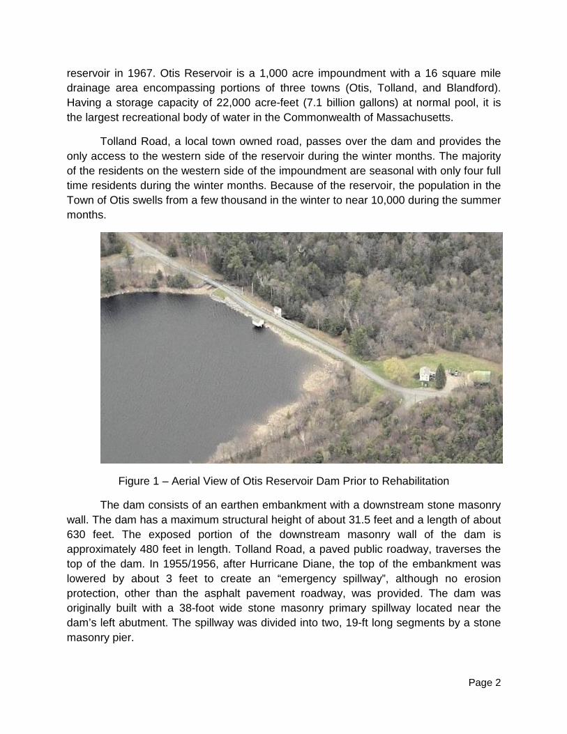
reservoir in 1967. Otis Reservoir is a 1,000 acre impoundment with a 16 square mile drainage area encompassing portions of three towns (Otis, Tolland, and Blandford). Having a storage capacity of 22,000 acre-feet (7.1 billion gallons) at normal pool, it is the largest recreational body of water in the Commonwealth of Massachusetts.
Tolland Road, a local town owned road, passes over the dam and provides the only access to the western side of the reservoir during the winter months. The majority of the residents on the western side of the impoundment are seasonal with only four full time residents during the winter months. Because of the reservoir, the population in the Town of Otis swells from a few thousand in the winter to near 10,000 during the summer months.
Figure 1 – Aerial View of Otis Reservoir Dam Prior to Rehabilitation
The dam consists of an earthen embankment with a downstream stone masonry wall. The dam has a maximum structural height of about 31.5 feet and a length of about 630 feet. The exposed portion of the downstream masonry wall of the dam is approximately 480 feet in length. Tolland Road, a paved public roadway, traverses the top of the dam. In 1955/1956, after Hurricane Diane, the top of the embankment was lowered by about 3 feet to create an “emergency spillway”, although no erosion protection, other than the asphalt pavement roadway, was provided. The dam was originally built with a 38-foot wide stone masonry primary spillway located near the dam’s left abutment. The spillway was divided into two, 19-ft long segments by a stone masonry pier.

Page 3
Tolland Road, a town owned road, passes over the dam and the spillway. In 1995, MassHighway replaced the deteriorating existing bridge with a temporary, one lane, Bailey bridge. The Bailey bridge was intended to be in service for three years. A permanent, two-lane bridge slated to be constructed in 1998. However, the project was delayed and postponed apparently due to MassHighway’s bridge project prioritization. By 2009, the permanent bridge replacement at the Otis Reservoir Dam had been postponed until 2014.
Prior to the recent dam rehabilitation, there were two gatehouses/outlet structures at the dam. The original gatehouse was located on the upstream side of the embankment and was taken out of service in 1984, when the outlet works at the dam were rehabilitated. The original sluice gates, stems and operators were removed and a 4-ft by 8-ft box culvert with a steel trash rack was installed within the reservoir. The box culvert extends about 40-ft upstream of the dam. A downstream outlet tower was constructed with a second gatehouse opposite to the original upstream gatehouse. The outlet tower has two, 48-in square slide gates, one serves as a low level outlet and the other services as a midlevel outlet. The outlet tower also has a 10-ft wide by 3-ft high overflow weir at the same elevation as the primary spillway crest (with flashboard in place). The two, original 30-inch square stone sluiceways through the dam had been retrofitted with 26-inch square steel conduits and then grouted place.
The Otis Reservoir is operated by the DCR’s park staff according to an Order of Conditions from the Otis Conservation Commission, which defines the target seasonal reservoir levels and governs the rates of reservoir drawdown and refill. In October, the DCR opens the outlet gates to provide 300± cfs for an annual weekend canoe race. The DCR dials back the release to lower the reservoir about 2 inches per day until the winter pool elevation (6 to 8 feet below summer pool) is reached. The purpose of the annual drawdown is to allow for the inspection of the dam structure, to prevent ice damage to the shoreline docks and piers, and to provide melt water storage and discharge control during the spring freshet. Beginning in January, the DCR begins to raise the reservoir level. The reservoir is raised to within 4 feet of the summer pool by April depending on the ice conditions. The goal is to have the reservoir level restored to the summer pool level by July 4th each year. The 1984 vintage outlet works configuration requires constant adjustment to manage the reservoir level, especially prior to or after storm events.
With the winter pool being maintained by releasing water from the low level outlet in the downstream outlet tower, the DCR could not easily monitor the water level below the ice. An excessive water release could cause the development of a void between the bottom of the ice and the surface of the reservoir. This was a major safety concern given the year-round recreational use of the reservoir, which includes ice fishing and snowmobiling on the reservoir. The DCR’s staff would use a chain saw to cut holes

Page 4
through the ice to evaluate the reservoir level. Obviously, this practice was not an ideal approach. So, the DCR indicated they would like to have the dam rehabilitation project also include provisions to improve the reservoir operation procedures.
Phase II Engineering Evaluation and Alternatives Analysis Following an inspection of the dam in May 2006 by GZA, the dam was judged to be in “Poor” condition. The primary deficiencies were:
• The deteriorated masonry and leakage conditions at the spillway and downstream masonry wall; and
• The erodibility of the “emergency spillway” over the main embankment section of the dam.
Figure 2 – Overview of the deteriorated and leaking conditions at the spillway prior to rehabilitation. In 2007, GZA GeoEnvironmental (GZA) was contracted by the DCR to perform a
Phase II Engineering Evaluation and Alternatives Analysis of the dam. This study included field investigations including wetland delineation, topographic survey of the dam and nearby areas, rare species determinations, diving inspections, subsurface explorations with test borings, and taking additional readings from the existing instrumentation at the dam. GZA’s engineering evaluations included interpretation of the subsurface conditions from the test borings, laboratory testing, and instrumentation

Page 5
readings; and conducting engineering analyses including a detailed hydrologic and hydraulic analyses, liquefaction, and seismically induced settlement analyses, seepage analyses, slope stability analyses and gravity wall stability analyses.
With Otis Reservoir Dam being a Large, High Hazard Dam per the
Massachusetts Dam Safety Regulations, its Spillway Design Flood (SDF) is the one half Probable Maximum Flood (1/2 PMF). The results of our detailed hydrologic and hydraulic analyses revealed the original spillway was capable of passing only 10 percent of the SDF and overtopping of the dam by about 3.3 feet was predicted. Our detailed seepage and stability analyses indicted the dam met most of the stability requirements set forth in the dam safety regulation except for the load case where the dam was overtopped during the SDF event. The factor of safety against sliding for the downstream masonry wall was below the required minimum due to the likelihood for erosion to occur at the base of the wall.
GZA conducted and facilitated a Potential Failure Mode Analysis (PFMA) with
several members of GZA’s engineering team and representatives from DCR responsible for the operation and maintenance of the dam. The objective of the PFMA was to assess possible failure modes and the failure mechanisms that are most likely, thereby allowing the design of the rehabilitation project to address each of the deficiencies.
Using the information obtained from the detailed engineering evaluations and the PFMA, GZA performed an Alternatives Analysis to evaluate the repair/rehabilitation options to address the dam safety issues. The alternatives included: No Action, Breach/Remove, Raise the Dam, Construct an Emergency Spillway, and Spillway Modification/Reconstruction. Spillway Reconstruction along with raising the crest of the dam was selected as the Preferred Alternative.
Selection of the Preferred Alternative To address both the dam safety issues and operational issues, reconstructing the
spillway with a bottom-hinged, 7.5-ft tall by 38-foot wide steel crest gate was selected as the Preferred Alternative. When the crest gate is in the “up” or “closed” position, the top of the gate is at the current normal summer pool elevation for the reservoir. The invert of the new spillway (i.e. with the crest gate in the “down” or “open” position) was set at the winter pool elevation; so that once the reservoir was drawn down it could “self-regulate the reservoir level without constant assessment and adjustment by the DCR staff.
To safely pass the ½ PMF SDF, the DCR staff will need to lower the summer reservoir level by 2 feet in advance of the ½ PMF event and then operate the gate throughout the storm to prevent overtopping of the dam. Without proper gate operation,

Page 6
the dam will be subject to overtopping during the ½ PMF SDF event. However, the proposed dam modifications would allow the spillway to safely pass the 500-year flood event with about 2 feet of freeboard without any crest gate operation.
Typically, relying on human operations to pass the SDF is not a recommended practice. The reason being is the potential for improper or lack of operation resulting from the absence of a human operator at the dam prior to or during flooding events. Otis Reservoir Dam is not a typical dam since it has full-time staff responsible for the operation of the dam located in DCR’s Tolland State Forest Office at the right abutment of the dam. DCR also has staff who live locally who are “on-call” should an emergency situation develop at the dam. Therefore, the design of the new spillway was able to take advantage of DCR’s somewhat unique onsite staffing situation.
Other improvements that were included in the dam rehabilitation were: raising the top of the dam by 3 feet, repointing the downstream masonry wall, extending the downstream toe drain, adding a reinforced concrete splash pad at the base of the downstream masonry wall, restoring the riprap slope protection on the upstream and portions of the downstream slopes, and installing new slide gates inside the downstream outlet tower.
Figure 3 – Schematic View of Repairs/Improvements
The Access Issue Access to the west side of the reservoir was identified as a critical issue early in
the project development. The Town fully understood the benefit of the project; however, they were concerned about the potential for short term impacts on the recreation season based economy. So, GZA worked with the DCR to evaluate concepts and options to address these conditions.
Repair downstream masonry, Construct Toe drain
Raise top of dam, Improve roadway alignment and pedestrian access Demolish upstream gatehouse,
Rehabilitate upstream slope
Reconstruct spillway and bridge Rehabilitate outlet tower controls

Page 7
Initially, a bypass route upstream of the spillway was evaluated. A temporary earthen embankment was considered to convey traffic around the spillway construction while also serving as a temporary cofferdam for the work area. A significant amount of fill would need to be placed in the wet. This option was eliminated when the constructability, cost and permitting requirements were evaluated more closely.
A second approach considered was to construct the spillway in two segments: upstream and downstream. The existing Bailey bridge would be left in place initially to allow the upstream portion of the spillway to be constructed. The Bailey bridge would be moved to the upstream side of the dam and the downstream half of the spillway would then be constructed. However, this option was also eliminated when the costs associated with the phased construction, the extended construction duration, the need for a more robust temporary cofferdam capable of remaining in place throughout the higher summer pool season, and the additional risks were evaluated more closely.
To limit the impact of the project on the recreational use of the reservoir, it was decided that the majority of the work needed to be performed in off-season (i.e. winter construction). It was also obvious that with the significant improvements being considered for the spillway, it did not make sense to reinstall the temporary Bailey bridge over the newly reconstructed spillway. So, the DCR decided incorporate a permanent bridge replacement into the dam rehabilitation project. In exchange for adding the new bridge to the project, the DCR was granted permission from the Town to close Tolland Road for 5 months.
To address the access issue to the west side of the reservoir, a detour route was created and maintained around the reservoir during the 5 month period when the bridge was closed. The detour route, which was about 8 miles in length, included a 2.8 mile section of gravel road that was typically not plowed/open during the winter. The DCR included as part contract a provision for liquidated damages to be levied against the contractor if the bridge/spillway was not reopened on time. The Town accepted the DCR’s offer for the new bridge and granted them permission to close Tolland Road for 5 months.

Page 8
Figure 4 – Detour Route During Construction.
Combining Dam and Bridge Design The design of the dam rehabilitation and the bridge replacement occurred
between 2007 and 2010. GZA provided overall engineering design for the dam including the hydrologic/hydraulic, geotechnical, and civil designs. GZA retained Wright-Pierce of Topsham, Maine to provide structural, mechanical and electrical engineering design services for the new crest gate and for two new slide gates in the outlet tower. Under a separate contract, the DOT engaged Amman Whitney of Boston, Massachusetts to perform the bridge design. DCR supervised the bridge designer while reporting progress to DOT. GZA was responsible for all design coordination and merging of the contract documents into a single bid package. GZA served as the overall project manager for the combined project and served as the Engineer-of-Record for the dam rehabilitation.
A performance specification was created for the crest gate. Local, qualified crest gate manufacturers were consulted to provide input in establishing the crest gate design criteria and to understand the implications of the DCR’s intended operation procedures. The DCR was committed to providing redundancy with the crest gate operations. The DCR wanted the gate to have twin, top mounted actuators, but they also wanted to have the ability to operate the gate with one actuator in the event that one failed. Based on this requirement, a hydraulically actuated operation system was selected for the project.

Page 9
Flow fuses were also added to the system to prevent the gate from opening unintentionally in the event of power loss or loss in hydraulic pressure.
With the reservoir’s history of a winter drawdown, the DCR needed to operate the gate in the winter. The rubber side seals and the invert seals of the crest gate could be significantly damaged if operated with ice accumulations. As such, robust electric side seal and invert heaters were incorporated into the structure. Operational procedures to turn on the heaters in advance of any winter gate operations were also written into the Operations and Maintenance Plan of the crest gate.
Figure 5 – Wright Pierce’s Crest Detail (Sheet S4)
The existing masonry spillway was removed and replaced with a reinforced concrete structure to support the crest gate and to convey the spillway flow through the dam. The training walls of the spillway discharge channel also served as the bridge abutments for the new bridge. GZA worked closely with the Wright-Pierce, the structural designer for the spillway and Ammann & Whitney, the bridge designer to ensure both elements of the project were proceeding with the same project vision.
The bridge was designed to meet ASSTHO Standards. Several bridge types were considered in the early part of the project. Initially, the bridge types considered included:
1. Single span, precast, prestressed concrete spread box beams with cast-in-place concrete deck.
2. Single span, rolled steel stringers with a cast-in-place deck. 3. Single span, built up steel plate girders with a cast in place deck.

Page 10
4. Single span, rolled steel stringers with a timber deck.
The initial bridge type recommendation was the single span precast concrete spread box beams with cast-in-place deck. However, the winter construction schedule and the limited road closure, precluded any of the bridge types that used cast-in-place decks. As such, other bridge types using prefabricated elements were considered. These bridge types included:
1. Prefabricated Bridge Units (formally known as Inverset) 2. NEXT Beam System 3. Fiber Reinforced Polymer (FRP) deck on steel stringers 4. Full Depth precast concrete deck panels on concrete or steel stringer. 5. Butted boxes/Deck Slab with no cast-in-place deck.
After considering the impacts, the prefabricated concrete/steel composite superstructure units with an asphalt wearing course was chosen. The main benefit of this bridge type was that the units could be prefabricated concurrent with the spillway construction. Thus, it could be brought onsite and lowered into place once the spillway training walls/bridge abutments were completed. This option gave the project the highest probability of success.
Figure 6 – Ammann & Whitney’s Typical Bridge Section (Sheet SB2)
Adding Stop Logs to the Spillway With the two phased, winter-only construction schedule, coupled with the 5
month road closure limitation, the total construction schedule for the project was pushed into a two-year duration. And, with the crest gate design, submittal review process, and fabrication requiring up to 6 to 8 months, the crest gate installation was slotted for the

Page 11
second winter construction season. This would not be possible with the project award in the fall and the spillway construction needing to be done by the winter. To accommodate this scheduling issue, upstream stop logs were added to the project. The addition of the upstream stop logs provided the following benefits:
1. The stoplogs provide a permanent mechanism to allow the crest gate to be taken off line for servicing and maintenance.
2. The stoplogs could be installed early in the spillway construction to limit the amount of time needed for a temporary cofferdam for the project.
3. The stoplogs could be installed and kept in place to serve as the water control mechanism until the crest gate was fully installed. This would allow the crest gate design, submittal review and fabrication to proceed without the added pressure of being the critical path element for the project.
4. The stoplogs would be used to create controlled upstream water condition to allow for testing of the crest gate and to train the DCR staff operations staff.
Figure 7 – GZA’s Reconstructed Spillway and New Bridge (Sheet C3)
Project Financing
With project design and constructability issues resolved, the next step was to figure out how the project would be funded. GZA’s initial construction cost estimate was on the order of $2 million. The DCR Office of Dam Maintenance used this figure in their capital planning for FY2010/2011. However, the initial cost estimate did not include a

Page 12
new bridge nor did it consider a two season construction schedule. Consequently, the updated cost estimate was significantly higher, on the order of about $3 million. To address the cost increase, the DCR needed to look at other options.
The project now included a new bridge; therefore, it should be partially funded with “bridge monies”. With the inclusion of the bridge replacement, the project could be partially funded with bridge repair appropriations. The bridge and portions of the spillway construction which served a dual capacity (both spillway training walls and bridge abutments) were funded via the Accelerated Bridge Program and not through the DCR-Office of Dam Maintenance dam rehabilitation budget. Second, the non-recreation construction season requirement caused the project to extend over two fiscal years. Consequently, the DCR was able to spread the project budget out over two years which provided them with greater fiscal flexibility when compared to the initial approach when the dam rehabilitation was scheduled to occur over one construction season.
Even though, the project scope and budget were increased by the addition of the bridge replacement to the project, the DCR, the Town of Otis and the general public benefited in a greater way with the expanded project scope and the DCR’s ability to see the big picture.
Phase I Construction Highlights The project was advertised for bid in the summer of 2010. The project was
awarded to the low bidder, MIG Corporation of Acton, Massachusetts, and construction began in September 2010.
On September 15, 2010 the DCR and the Contractor began Phase I of construction. Approximately one month later, the portion of Reservoir Road across the top of the dam was officially closed and the detour route around the site was established. The Phase I work included: the downstream splash pad, toe drain, raising of the embankment crest by 3 feet, placement of new upstream and downstream riprap slope protection, demolition of the masonry spillway, construction of the new reinforced concrete spillway/bridge abutments, installation of the new stoplogs, installation of the new bridge, demolition of the upstream gatehouse, and construction of the new crest gate gatehouse at the left abutment.

Page 13
Figure 7 – Improvements to the Dam Crest and Upstream Slope
Bedrock excavation and removal within the spillway footprint was required to allow the invert of the crest gates to be at the winter pool elevation while fully open. Rock excavation was accomplished with a combination of ripping with an excavator and hoeramming. Figure 6 shows an example of typical rock excavation at the spillway. Line drilling was used occasionally to help control the limit of the rock removal. Continuous and event specific vibration monitoring was performed for the existing downstream masonry face of the dam and at the downstream gatehouse/outlet tower and at locations where concrete was being poured concurrently with rock excavation.
Figure 8 – Bedrock Excavation at the Spillway

Page 14
The bedrock surface at the proposed spillway was less competent than was accounted for in the design. At the east training wall, competent bedrock was found to be up to 3.5 feet below the proposed bottom of footing elevation. Vertical joints, seams, and open fractures observed in the area of the crest gate footings were “choked” with concrete. Sound bedrock was deeper than anticipated, so additional concrete placements were required to reach the design bottom of footing elevations. In addition, at the east bridge abutment, a “shear key” was added to the east abutment footing, due to a lower than anticipated bedrock elevation at the downstream end of the footing, and observed bedrock fracturing.
December 2010, marked the beginning of concrete placement for the new spillway. December 2010 also marked the beginning of one of the coldest winters in recent years in the Berkshires. As shown on Figure 7, concrete was formed and poured in heated tents, and was typically allowed to cure for at least three days within the heated tents prior to stripping forms. Rock excavation was not allowed for 24 hours after concrete had been poured on the site, and backfilling was not permitted for 28 days after pouring concrete, unless field cured cylinders indicated that the training walls had reached the required 28-day compressive strength. The stoplog bays, crest gate footings, upstream and downstream training walls, and bridge abutments were all poured throughout the winter in this manner with great success. Side seals and heating elements for the hydraulic crest gates were installed as part of the training wall construction.
Figure 9 – Winter Concrete Work at the Spillway
Page 15
By February 2011, work on the spillway had progressed sufficiently to allow backfilling between the existing embankment and spillway training/abutment walls. Freezing daily and nightly temperatures required a diligent effort on the Contractor’s part to provide ground heaters and frost blankets. Because of the relatively high fines content of the new embankment fill material, moisture content significantly impacted the Contractor’s ability to compact the material to the required density. The material was brought to the site with a moisture content well over its optimum moisture content. This condition, in addition to the rainy/wet weather becoming more prevalent in the spring of 2011, caused delays in the backfilling operation. Despite the harsh conditions, the backfilling was completed, the stoplogs were installed, and the temporary cofferdam was removed in time for the scheduled bridge/road reopening on March 15, 2011.
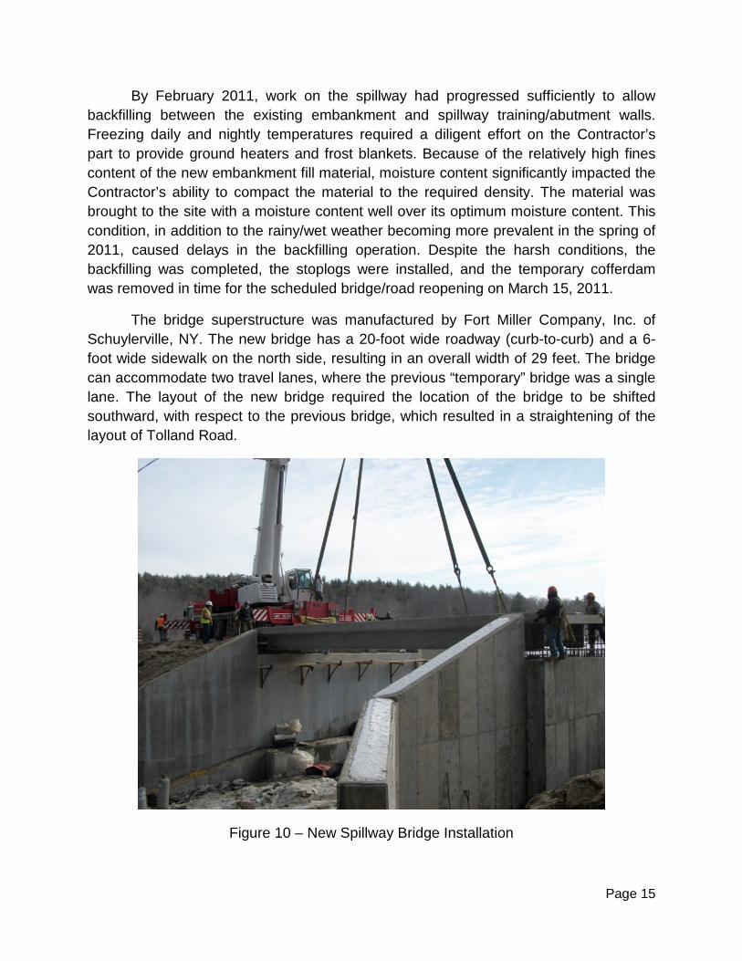
The bridge superstructure was manufactured by Fort Miller Company, Inc. of Schuylerville, NY. The new bridge has a 20-foot wide roadway (curb-to-curb) and a 6-foot wide sidewalk on the north side, resulting in an overall width of 29 feet. The bridge can accommodate two travel lanes, where the previous “temporary” bridge was a single lane. The layout of the new bridge required the location of the bridge to be shifted southward, with respect to the previous bridge, which resulted in a straightening of the layout of Tolland Road.
Figure 10 – New Spillway Bridge Installation

Page 16
A Little More than Just a “Wet Test” Between Phases I and II, on August 27-28, 2011, Otis Reservoir received
between about 7 and 10 inches of rainfall from Tropical Storm Irene. DCR began to lower the reservoir level with the outlet gate two days prior, in anticipation of the storm. The outlet gate was kept open during and after the storm as well. By the time the storm hit, the DCR removed up to three rows of stoplogs (1.5 feet). The reservoir level eventually rose to about 12 inches over normal pool on August 29, 2011, which is about 6 inches above the maximum reservoir level used to design the stoplogs. On September 1, 2011, the DCR reported that the three rows of stoplogs had been replaced and gate in the outlet tower was closed. The DCR inspected the spillway and did not observe any noticeable damage.
Figure 11 – Spillway Flow due to Tropical Storm Irene
Phase II - The Home Stretch The Contractor re-mobilized to the site full-time in October 2011 to begin Phase II
of the project. Final pavement of the road and bridge was placed and pedestrian access components were completed. Construction of the new gatehouse began concurrently with the installation of the hydraulically actuated crest gate. The new gatehouse was constructed on the left (west) side of the spillway to 1) house equipment and controls

Page 17
associated with the hydraulic crest gate; 2) house the remote water level instrumentation system; and 3) provide secure storage for the aluminum stoplogs.
The crest gate, which had been fabricated by Rodney Hunt of Orange, Massachusetts, was installed by the end of December 2011. The hydraulic system was installed and tested as part of the “dry test” in January 2012. A “wet test” of the crest gate system was also performed shortly thereafter. Although the reservoir was at the winter pool elevation, water could be pumped from the reservoir into the area between the stoplogs and crest gate. So, once again, the inclusion of the stop logs provided a benefit to the project that went beyond their primary objective.
The crest gate system was substantially complete by mid-March, 2012, when a training session was held for the DCR personnel who would be operating the system.
Figure 12 – Completed Hydraulic Crest Gate
The new slide gates were installed in-the-wet inside the downstream tower on the upstream face. The new gates include new electric actuators (with manual backup). The gates were installed with a grout bedding. However, during testing, the slide gates leaked significantly through the grout bedding at the gate flange and from the anchor bolt holes. Several repair attempts were made; however, the leakage remained beyond the specified allowable limit. The DCR is currently evaluating repair options to address the leakage.
Summary The Otis Rehabilitation Dam and Bridge Rehabilitation project was a success.
The planning efforts, which were initiated by the dam safety inspections, led to a project that has benefited the DCR, the Town of Otis, and the general public. The crest gate spillway provides the needed hydraulic capacity to the dam to mitigate overtopping and the potential failure of a High Hazard dam. The crest gate also provides a self-regulating

Page 18
winter pool level which significantly improves the DCR’s reservoir operations. The new bridge replaces a temporary, one lane bridge that was in-place for approximately 15 years beyond its intended service life and provides a permanent, two-lane bridge that will benefit the users of the Otis Reservoir. Even though the project initially started out with the primary goal of addressing the dam safety issues at the dam, the evolution of the project ultimately provided a broader and more substantial benefit to each of the project stakeholders.
Figure 13 – Upstream view of the completed dam.