the madness continues - triumphclub-joburg.co.za
TRANSCRIPT
1
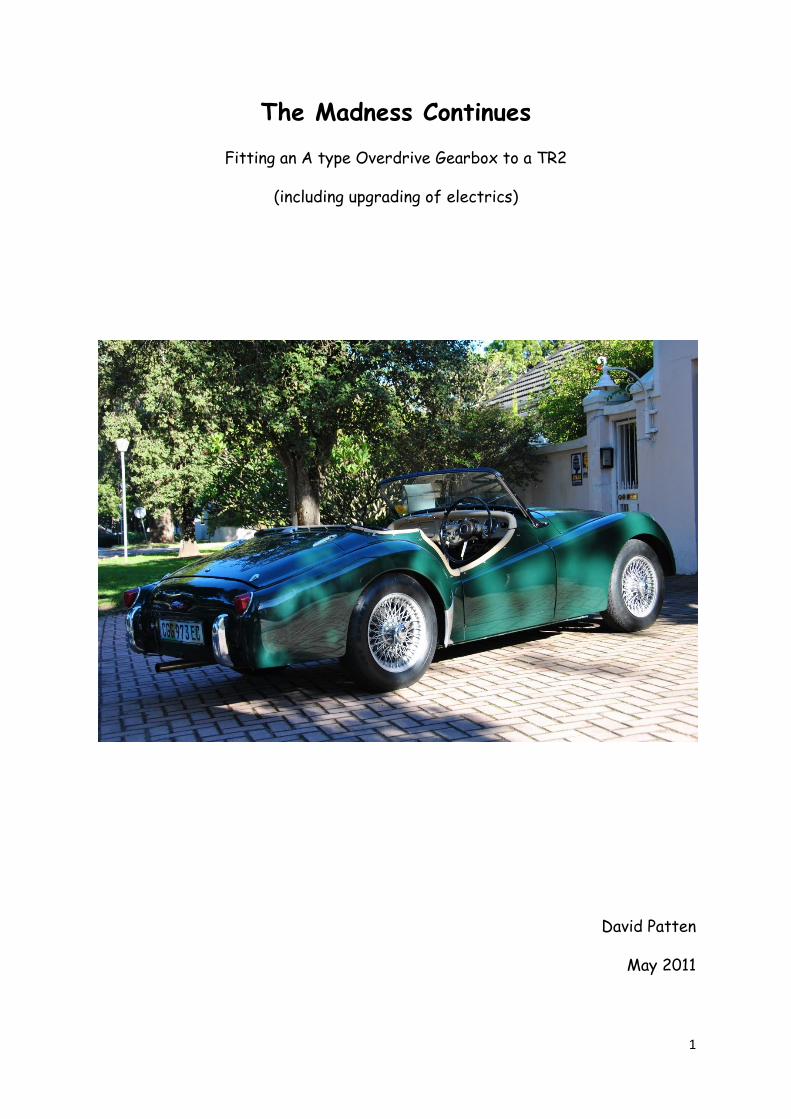
The Madness Continues
Fitting an A type Overdrive Gearbox to a TR2
(including upgrading of electrics)
David Patten
May 2011
2
Index
Paragraph
1. Acquisition of Overdrive Gearbox. 3
2. Solenoid and Speedometer Drive. 4
3. Clutch Release Bearing, Carrier, Cross Shaft and Fork. 4
4. Gearbox Input Shaft and Clutch. 5
5. Overdrive Isolating Switches. 6
6. Gearbox Connecting Flange to Prop Shaft. 7
7. Gearbox Mounting. 7
8. Fitment of Gearbox. 7
9. Modifications to Accommodate Solenoid. 8
10. Electrics. 9
11. Gear Lever 10
12. Trials and Tribulations. 10
13. Conclusions. 11
14. Gearbox Details 11
Annexure 1: Supplementary Wiring Diagram TR 2 12
3
1. Acquisition of Overdrive Gearbox.
I only sourced an Overdrive gearbox after completion of the rebuild of my TR2
so its fitment became a post rebuild project. The only Triumph overdrive
gearbox I could get locally at the time was an A type which turned out to be a
basket case as the main shaft was damaged beyond repair. On complaining, the
scrap yard miraculously found another unit that appeared to be seized but
fortunately, on opening was found to be fine. The task of rebuilding the gearbox
and overdrive was initially given to Owen Chandley of Emanual Gearbox Repairs
who unfortunately passed away before he could complete the job, so the
gearboxes were retrieved and passed on to Eddie Jansen to affect the work and
get one serviceable gearbox and overdrive from the two.
When the rebuilt box was received back from Eddie I procrastinated fitting it
to my rebuilt TR2 as I was loath to remove all the beautifully fitted carpeting,
however my hand was eventually forced when the car started jumping out of
second gear with selection of all gears becoming increasingly difficult.
I was now faced with the task of effecting the final adjustments and
modifications required in order to fit the unit. However before commencing
operations I checked through past copies of Sabrina and found that two
articles had previously been published on the subject, the first by Brian Brown,
“Overdrive Box Conversions on TR2/3/3A” ( December 1990), and the second by
Brian Richards titled “Sidescreen Workshop, Triumph 2500 Gearbox and
Overdrive Conversion” (September 2006). Both these articles were of
assistance and encouragement in tackling this task, though the latter was more
relevant to the J type gearbox.
The trials and tribulations experienced in tackling this task have encouraged me
to document a more detailed account of what was required, which I hope will be
of assistance to anyone else embarking on such a project.
Both the A type overdrive gearboxes I had acquired in order to achieve a
working rebuilt unit, had a number of external parts missing which proved to be
difficult and costly to source, i.e. overdrive solenoid, speedometer drive and
bearing, clutch cross shaft and lever end together with fork, as well as the
carrier for the release bearing. In addition neither of the overdrive gearboxes
4
had provision for the fitment of the isolator switches on the gearbox covers,
which I found very strange.
Had I realised the above when purchasing the overdrive unit I would certainly
have been in a strong position to negotiate down the original purchase price.
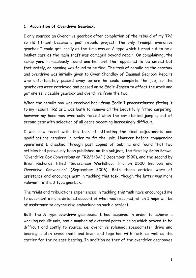
2. Solenoid and Speedometer Drive.
I was fortunately able to obtain a second
hand solenoid from Charles Mitchell but
the speedometer drive and bearing proved
more difficult and was ultimately sourced
from Moss UK. However without a sample
or knowledge of what the speedometer
drive and bearing looked like it was
difficult to identify the correct part as
there are a few variations. As to be expected the one initially supplied was
incorrect and had to be returned. This not only was a bit of a mission but also
costly.
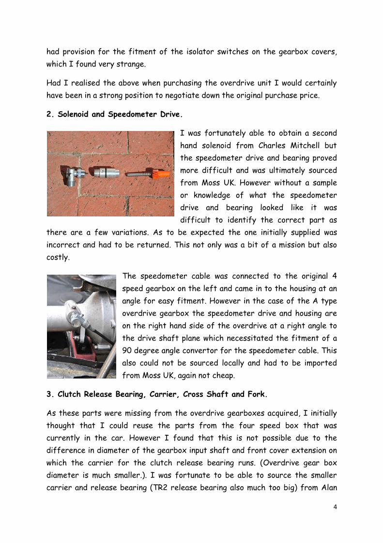
The speedometer cable was connected to the original 4
speed gearbox on the left and came in to the housing at an
angle for easy fitment. However in the case of the A type
overdrive gearbox the speedometer drive and housing are
on the right hand side of the overdrive at a right angle to
the drive shaft plane which necessitated the fitment of a
90 degree angle convertor for the speedometer cable. This
also could not be sourced locally and had to be imported
from Moss UK, again not cheap.
3. Clutch Release Bearing, Carrier, Cross Shaft and Fork.
As these parts were missing from the overdrive gearboxes acquired, I initially
thought that I could reuse the parts from the four speed box that was
currently in the car. However I found that this is not possible due to the
difference in diameter of the gearbox input shaft and front cover extension on
which the carrier for the clutch release bearing runs. (Overdrive gear box
diameter is much smaller.). I was fortunate to be able to source the smaller
carrier and release bearing (TR2 release bearing also much too big) from Alan
5
Dickens in Bloemfontein. Luckily I was able to reuse the clutch cross shaft and
lever end together with the fork, from the four speed gearbox. However due to
the smaller diameter of the release bearing carrier, the locating pins on the
fork were too short to engage in its slot. Consequently new locating pins were
machined to fit by Robbie Deysel Engineering.
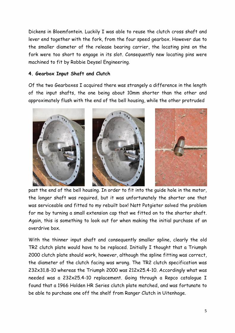
4. Gearbox Input Shaft and Clutch
Of the two Gearboxes I acquired there was strangely a difference in the length
of the input shafts, the one being about 10mm shorter than the other and
approximately flush with the end of the bell housing, while the other protruded
past the end of the bell housing. In order to fit into the guide hole in the motor,
the longer shaft was required, but it was unfortunately the shorter one that
was serviceable and fitted to my rebuilt box! Natt Potgieter solved the problem
for me by turning a small extension cap that we fitted on to the shorter shaft.
Again, this is something to look out for when making the initial purchase of an
overdrive box.
With the thinner input shaft and consequently smaller spline, clearly the old
TR2 clutch plate would have to be replaced. Initially I thought that a Triumph
2000 clutch plate should work, however, although the spline fitting was correct,
the diameter of the clutch facing was wrong. The TR2 clutch specification was
232x31.8-10 whereas the Triumph 2000 was 212x25.4-10. Accordingly what was
needed was a 232x25.4-10 replacement. Going through a Repco catalogue I
found that a 1966 Holden HR Series clutch plate matched, and was fortunate to
be able to purchase one off the shelf from Ranger Clutch in Uitenhage.

6
On refitting the pressure plate with the new clutch in place, to my horror one
of the bolts sheared off at the low torque
of only 20ft lbs. I was luckily able to
unscrew the broken bolt section by carefully
tapping it with a punch and light hammer. On
a close inspection of the other bolts I
noticed that a number of them had been
stretched through over tightening at some
time, so I replaced them all. Lesson learned.
5. Overdrive Isolating Switches.
As the covers to both the gearboxes I had acquired did not have provision for
isolating switches, I thought I could just swop over the cover from the old four
speed box as it had provision for overdrive conversion with removable plugs in
the threaded holes for the isolator switches. Unfortunately this was not
possible as the selector mechanism for reverse was different. I ended up taking
the gearbox cover to an engineering works and having the required thread
tapped to accommodate the isolator
switches. (I first checked to see that the
activation horns on top of the selectors
were in fact there!) The original TR’s had
overdrive on second, third and fourth, so I
decided to replicate this and fitted two
isolator switches.
The switches were imported from Moss UK together with the specified spacers
(one per switch). On reading the workshop manual a lot of importance was placed
on getting these switches correctly adjusted with spacers so as to not impede
gear selection. Accordingly I fitted the isolators with the spacers purchased,
but found that I could add another spacer made from gasket paper and the
switch still operated. (Two of these additional spacers and the switch would not
activate). I was very pleased with myself and thought that I had it perfectly
adjusted. However I ultimately discovered that by fitting my additional spacer
I had made the gap too fine as operating vibrations caused the switch to
oscillate, so I ended up removing them and sticking to the single spacers
supplied by Moss.
7
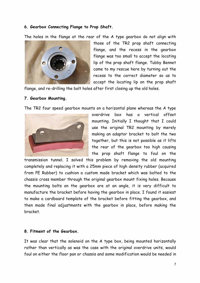
6. Gearbox Connecting Flange to Prop Shaft.
The holes in the flange at the rear of the A type gearbox do not align with
those of the TR2 prop shaft connecting
flange, and the recess in the gearbox
flange was too small to accept the locating
lip of the prop shaft flange. Tubby Bennet
came to my rescue here by turning out the
recess to the correct diameter so as to
accept the locating lip on the prop shaft
flange, and re-drilling the bolt holes after first closing up the old holes.
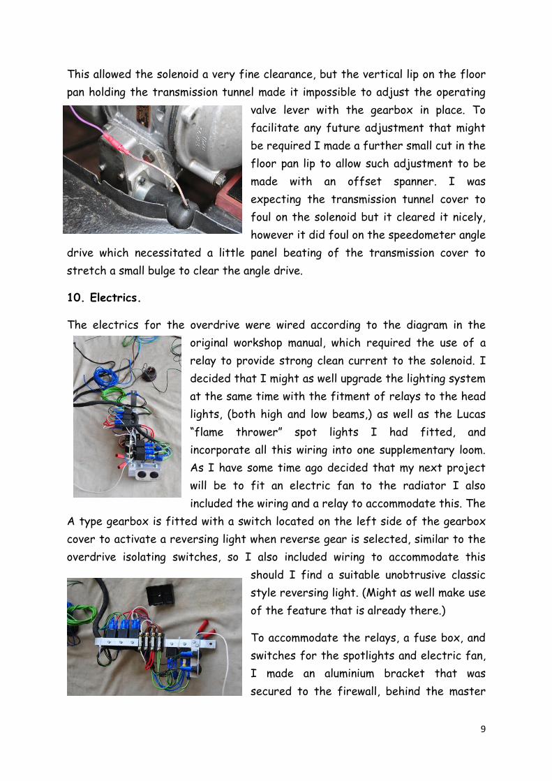
7. Gearbox Mounting.
The TR2 four speed gearbox mounts on a horizontal plane whereas the A type
overdrive box has a vertical offset
mounting. Initially I thought that I could
use the original TR2 mounting by merely
making an adaptor bracket to bolt the two
together, but this is not possible as it lifts
the rear of the gearbox too high causing
the prop shaft flange to foul on the
transmission tunnel. I solved this problem by removing the old mounting
completely and replacing it with a 25mm piece of high density rubber (acquired
from PE Rubber) to cushion a custom made bracket which was bolted to the
chassis cross member through the original gearbox mount fixing holes. Because
the mounting bolts on the gearbox are at an angle, it is very difficult to
manufacture the bracket before having the gearbox in place. I found it easiest
to make a cardboard template of the bracket before fitting the gearbox, and
then made final adjustments with the gearbox in place, before making the
bracket.
8. Fitment of the Gearbox.
It was clear that the solenoid on the A type box, being mounted horizontally
rather than vertically as was the case with the original overdrive units, would
foul on either the floor pan or chassis and some modification would be needed in

8
this respect. Accordingly I fitted the
solenoid and made the necessary
adjustments to the operating valve (as per
workshop manual recommendation) with the
gearbox on the bench, and then removed the
solenoid before fitting, to protect it from
damage.
With the clutch plate correctly aligned I found it easiest to lift the rear of the
engine a little before fitting the gearbox unit, and then with the gearbox bolted
to the motor lower the unit to facilitate finalising the gearbox mounting and
making modifications to accommodate the solenoid. To marry the gearbox to the
motor it has to be initially aligned with the gearbox rotated about 30 degrees
as the clutch release arm catches on the floor pan. The gearbox can then be
located on the clutch spline and then rotated back so as to fit on to the locating
pins once the clutch release arm reaches the broader opening in the floor pan.
This is actually a lot easier than it sounds but really is a two man job to do it
effectively, one under the car supporting the bell housing and locating the input
shaft, and the other in the cockpit pushing the box forward and rotating it once
the clutch release arm is clear. On bolting the gearbox bell housing to the block
I realised that the reused fixing bolts were too short as the flange on the bell
housing through which they pass is approx 10mm thick on the old four speed
unit, but on the A type box it is beefed up to about 15mm at the fixing points.
This necessitated purchasing longer bolts but unfortunately the correct length
required was not available so I had to settle for slightly longer ones and cut
them to size, which was necessary, especially for the three blind bolts at the
top of the bell housing. Similarly, the fixing bolts for the starter motor
required replacement with longer ones as well. The pushrod from the clutch
slave cylinder to the fork end that attaches to the clutch cross shaft lever also
had to be shortened by approximately 5mm to allow adjustment.
9. Modifications to Accommodate Solenoid.
With the gearbox in place it could easily be seen that the solenoid would foul on
the floor pan, and also very slightly on the cross member for the gearbox
mounting. To clear the solenoid, it was necessary to cut a small section away
from the floor pan and cross member, not affecting it structurally in any way.
9
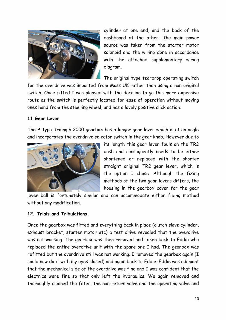
This allowed the solenoid a very fine clearance, but the vertical lip on the floor
pan holding the transmission tunnel made it impossible to adjust the operating
valve lever with the gearbox in place. To
facilitate any future adjustment that might
be required I made a further small cut in the
floor pan lip to allow such adjustment to be
made with an offset spanner. I was
expecting the transmission tunnel cover to
foul on the solenoid but it cleared it nicely,
however it did foul on the speedometer angle
drive which necessitated a little panel beating of the transmission cover to
stretch a small bulge to clear the angle drive.
10. Electrics.
The electrics for the overdrive were wired according to the diagram in the
original workshop manual, which required the use of a
relay to provide strong clean current to the solenoid. I
decided that I might as well upgrade the lighting system
at the same time with the fitment of relays to the head
lights, (both high and low beams,) as well as the Lucas
“flame thrower” spot lights I had fitted, and
incorporate all this wiring into one supplementary loom.
As I have some time ago decided that my next project
will be to fit an electric fan to the radiator I also
included the wiring and a relay to accommodate this. The
A type gearbox is fitted with a switch located on the left side of the gearbox
cover to activate a reversing light when reverse gear is selected, similar to the
overdrive isolating switches, so I also included wiring to accommodate this
should I find a suitable unobtrusive classic
style reversing light. (Might as well make use
of the feature that is already there.)
To accommodate the relays, a fuse box, and
switches for the spotlights and electric fan,
I made an aluminium bracket that was
secured to the firewall, behind the master
10
cylinder at one end, and the back of the
dashboard at the other. The main power
source was taken from the starter motor
solenoid and the wiring done in accordance
with the attached supplementary wiring
diagram.
The original type teardrop operating switch
for the overdrive was imported from Moss UK rather than using a non original
switch. Once fitted I was pleased with the decision to go this more expensive
route as the switch is perfectly located for ease of operation without moving
ones hand from the steering wheel, and has a lovely positive click action.
11.Gear Lever
The A type Triumph 2000 gearbox has a longer gear lever which is at an angle
and incorporates the overdrive selector switch in the gear knob. However due to
its length this gear lever fouls on the TR2
dash and consequently needs to be either
shortened or replaced with the shorter
straight original TR2 gear lever, which is
the option I chose. Although the fixing
methods of the two gear levers differs, the
housing in the gearbox cover for the gear
lever ball is fortunately similar and can accommodate either fixing method
without any modification.
12. Trials and Tribulations.
Once the gearbox was fitted and everything back in place (clutch slave cylinder,
exhaust bracket, starter motor etc) a test drive revealed that the overdrive
was not working. The gearbox was then removed and taken back to Eddie who
replaced the entire overdrive unit with the spare one I had. The gearbox was
refitted but the overdrive still was not working. I removed the gearbox again (I
could now do it with my eyes closed) and again back to Eddie. Eddie was adamant
that the mechanical side of the overdrive was fine and I was confident that the
electrics were fine so that only left the hydraulics. We again removed and
thoroughly cleaned the filter, the non-return valve and the operating valve and
11
blew the ducts out with a high pressure jet before reassembling the unit. I
spoke to Alan Dickens and he suggested that I try using normal multi-grade
engine oil (20W50) rather than the thicker 80W90 gearbox oil I had used.
Third time lucky, the overdrive worked! I am not sure whether it was the
thinner oil or a blockage in the hydraulics or both, but it was working. I was
however concerned that on activating the overdrive there was a short delay
before it kicked in, but deactivation was immediate. I discussed this with a
number people who have overdrive units and the responses vary, some saying
that it should be immediate and others that the slight delay is normal.
Brian Brown however had the view that these overdrive units are all rather old
now and consequently a little worn so when adjusting the operating valve one
should take the lever on the side of the overdrive a little past the 3/16th
setting hole which will eliminate the delay.
An interesting view. However, I have not yet tested this theory as at the
moment I am happy that the unit is working well and is adjusted in accordance
with the workshop manual.
13. Conclusions.
The overdrive and synchromesh on first gear make a tremendous difference and
it is certainly well worth the effort of conversion. The overdrive gearbox has a
much nicer feel than the old four speed box, though I am not sure of the
usefulness of overdrive on second and third, but that’s what the early TR’s had.
However I can now say I have a seven speed box though I guess overdrive will
be mainly used on top gear where it really transforms the car, substantially
dropping the revs and giving a more comfortable ride.
14.Gearbox Details
Gearbox number; 306812 SM ; Overdrive serial number 22/61711/019986
Gearbox Type: Laycock de Normanville overdrive unit (A Type)
Made by Laycock Eng. Ltd Sheffield England under licence from Auto
Transmissions Ltd Coventry England

12

13
Key for Wiring Diagram.
1 Blue 17 Green 41 Red
2 Blue with red 18 Green with red 49 Purple
4 Blue with white 21 Green with white 56 Purple with black
5 Blue with green 24 Green with black 57 Black
9 White 33 Brown 58 Black with red
16 White with black 40 Brown with black 62 Black with green