the class answer to the rapidly developing tug … class answer to the rapidly developing tug...
TRANSCRIPT

International Tug & Salvage Convention and Exhibition Vancouver, 17-21 May 2010
1
The Class Answer to the Rapidly Developing Tug Industry Gijsbert de Jong, Bureau Veritas, France SYNOPSIS: Comparison between the tug rules of different class societies shows that there are considerable differences in requirements. Apparently, standards are not at the same level, which is undesirable from a safety point of view and makes it difficult for yards and designers to develop standard tug designs. On top of that, the present day tug rules are not always up to date with regard to the latest technical developments, which creates difficulties for the certification of advanced equipment and systems. Class societies Bureau Veritas, Lloyd’s Register and American Bureau of Shipping acknowledge the industry’s pledge for more harmonisation and have created a ‘class JIP’ to develop safety guidelines for tugs, which will be submitted to IACS to seek class wide support. The project focuses on the key issues, such as design loads, stability, towing equipment, fire safety and life saving and safety management. Both normal towing as well as escort operations are considered. The latest industry developments are taken into consideration, including the results of the SafeTug I & II JIPs, to which all three class societies are participating. INTRODUCTION Operational requirements for tugs are becoming increasingly challenging and put high demands on the reliability and efficiency of both the ships and their crews. The general increase in size of merchant ships requires harbour tugs to have a higher bollard pull, which in turn increases the forces on the towing equipment, the fendering system and the ship structure (in particular the towing equipment foundations and push bow), while simultaneously pushing up the installed propulsion power. In addition, authorities and offshore terminal operators demand increased deploy-ability of escort and offshore terminal tugs, which have to assist ever larger ships in more severe weather conditions, including ice and arctic conditions.
Figure 1: Larger ships, more powerful tugs
The tug industry has responded by developing increasingly sophisticated and powerful tugs. Recent technical developments include hull form optimisation to increase the hydrodynamic lift on the hull of escort tugs (including special design skegs), the introduction of very powerful active render-recover winches and the deployment of ultra high strength towlines. In addition, novel tug
concepts have been introduced, such as the Z-Tech design by Robert Allan Ltd, the carrousel tug by Novatug BV and a number of designs for multi-functional salvage and emergency response tugs. In a more general sense, tug propulsion systems are being optimised with regard to power and efficiency, while the level of automation on board has increased dramatically. Finally, it is now widely acknowledged that environmental and energy efficiency issues, relating to the need for cleaner and more efficient tugs, need to be addressed. To this end a number of design and operational initiatives have been taken by the tug industry, such as the development of alternative propulsion systems and (LNG propulsion, fuel cell powering and hybrid propulsion systems) and the E
3 project [1,2,3,4].
Classification of tugs is a global market and ship owners can choose from a variety of class societies. Each society has its own particular knowledge and experience, upon which it draws to formulate its rules. A comparison of these rules shows that considerable differences do exist between the requirements of the different class societies. This validates the question whether there actually are differences in standards. In addition, these differences make it complicated to develop standard designs which would fit a variety of different owners, each with their preferred class societies and flags. Moreover, class rules are not always up to date with regard to the latest industry developments described above. This creates issues with respect to the development and certification of advanced designs, equipment and systems. These issues have been sounded by the industry, most notably by Robert Allan Ltd in a paper presented and discussed at ITS 2006 in Rotterdam [5].
International Tug & Salvage Convention and Exhibition Vancouver, 17-21 May 2010
2
Leading class societies Bureau Veritas, Lloyd’s Register and American Bureau of Shipping, which together oversee the classification of 64% of the world tug fleet classed with IACS members
1,
acknowledge and appreciate the industry’s pledge for more harmonisation and have created a ‘class JIP’ to investigate the technical background, coherence and applicability of the existing rules for tugs [6]. The goal of the project is to develop harmonised guidelines for the design and operation of tugs. The guidelines focus primarily on safety related issues, such as design loads, stability, towing equipment, fire safety, life saving appliances and safety management. The format of the guidelines is to be as open as possible in order to accommodate the proper assessment of new technical developments such as the active render-recover winches. Upon completion the document will be submitted to IACS in order to seek an even wider support base for the introduction of common safety standards for tugs. The project is carried out under the umbrella of the MARIN lead SafeTug II JIP, in which a large number of stakeholders in the tug industry (including tug operators, terminal operators/oil majors, tug designers, shipyards, tug equipment manufacturers and class societies) are working together to improve understanding of tug behaviour in offshore conditions, which provides insight into the effectiveness and operability of tugs in different operational modes. The advantages of integrating the ‘class JIP’ into the wider scope of the SafeTug II JIP are twofold. The first is that the results of hydrodynamic studies performed within SafeTug provide useful research data as background information for drafting commonly shared safety guidelines, for example with regard to tug stability in escort mode. The second advantage is that the JIP partners are actively providing feedback on the draft guidelines, which gives valuable opportunities for cross checking and sharing of knowledge and experience (e.g. from tug masters). The objective of this paper is to provide an overview of the key issues addressed within the harmonisation project and to inform the tug industry about the results of the work which has been done so far
2. A draft version of the
guidelines will be presented to and discussed with the SafeTug II participants during ITS 2010. After taking into account the industry feedback, the guidelines are expected to be published during
1 Source: Seaway, January 2010
2 It should be noted that the results presented in this
paper are preliminary and for information purposes only, and should not be considered as a substitution of the guidelines currently under preparation.
the summer of 2010. It is to be noted that the guidelines are intended for the design, construction and operation of new ships. Following the Introduction section, the section Regulatory framework provides an overview of the background on which the guidelines have been built, including the definition of specific service notations for tugs. The section Design load deals describes the key (design) loads which are to be taken into account, as well as how to obtain them. Specific attention is paid to escort operations. The following three sections, Towing stability, Towing equipment and Safety equipment, provide details on the specific recommendations developed within the scope of the project, while the section Assisted ship considers recommendations with regard to the towing fittings and tug pushing areas of the side structure of the ship being assisted by a tug. The section Safety management provides guidance for a (voluntary) safety management system for the tugs of less than 500 gt. Finally, the Closure section will provide some conclusions and notes regarding the follow-up of the project REGULATORY FRAMEWORK
One of the key points with regard to creating
safety guidelines for tugs is to acknowledge that
tugs are operating in a number of different modes
and that each of these modes imposes different
design requirements. In fact, a tug is largely
defined by its operational profile and the general
lay-out, hull form, propulsion system and towing
equipment are designed on the basis of this
profile. Quite obviously, there are big differences
between a tug designed for berthing/unberthing of
ships in port (harbour tug) and a tug designed for
offshore salvage operations under adverse
weather conditions (offshore salvage tug).
However, in most existing rules and regulations
there is not much difference in the applicable
requirements and the associated class service
notation is just tug. An exemption is made for
escort tugs, for which most class societies have
issued additional requirements, in particular with
respect to stability.
The guidelines take the variation in applicable
tasks and the associated weather conditions
explicitly into account by defining a set of service
notations which clearly specify the nature of
operation of the tug as well its operational profile.
The class requirements for each type of tug then
become a (logical) function of the service
notation(s) selected by the designer.

International Tug & Salvage Convention and Exhibition Vancouver, 17-21 May 2010
3
The service notations in the guidelines are based
on the following set of tug definitions, which are
considering both tasks to be performed, as well
as the associated operating area.
Harbour tugs are considered to assist ships
and/or units while entering or leaving port and
during berthing and unberthing operations.
Harbour tugs are considered to navigate in calm
stretches of water (sheltered area). Normally,
harbour tugs work from a fixed port. The crew is
very familiar with the operating area and shore
side facilities for maintenance, repairs, spare
parts, etc. are directly available. In case of
emergency shore side assistance is directly
available. Seagoing tugs are considered to assist ships and/or units in ports as well as at sea. Seagoing tugs can either operate without any restriction (deep sea towage, in any sea area and any period of the year) or within short distance from shore (coastal towage) or at a specified location (offshore terminal tugs). For coastal towage and offshore terminal tugs the crew is considered to be familiar with the operating area and shore side facilities for maintenance, repairs, spare parts, etc. are readily available. It is also considered that in case of emergency shore side assistance is readily available if the tug does not proceed in the course of the voyage more than four hours at operational speed from a place of safe sheltered anchorage. For deep sea towage the crew is not necessarily familiar with the operating area and shore side facilities for maintenance, repairs, spare parts, etc. are generally not readily available. It is also considered that in case of emergency shore side assistance is not readily available. Escort tugs are considered to be specifically engaged in (emergency) steering, braking and otherwise controlling of ships and offshore units during navigation, typically sailing at a speed in excess of 6 kn. Escort tugs can operate in (confined) sheltered waters, as well as in open sea areas. If escort tugs operate from a fixed station, the crew is familiar with the operating area and shore side facilities for maintenance, repairs, spare parts, etc. are readily available. It is considered that in case of emergency shore side assistance is readily available if the tug does not proceed in the course of the voyage more than four hours at operational speed from a place of safe sheltered anchorage. If escort tugs are engaged in deep sea voyages it is considered that the crew is not necessarily familiar with the operating area and shore side facilities for maintenance, repairs, spare parts, etc. are generally not readily available. It is also
considered that in case of emergency shore side assistance is not readily available. On the basis of these definitions, the following service notations are proposed: harbour tug (maximum bollard pull = T kN) for ships specially equipped for towing and/or pushing within the limits of a port tug (maximum bollard pull = T kN) for ships specially equipped for towing and/or pushing in offshore conditions optional additional service feature: sailing time ≤ 4 h from a safe sheltered anchorage
escort tug (maximum steering force = TY kN at speed VY kn, maximum breaking force = TX at speed = VX kn)
for ships specially equipped for towing/and or pushing, having equipment for escorting ships or floating units during navigation. Escorting is considered to include (emergency) steering, braking and otherwise controlling the assisted ship or floating unit during navigation, typically moving at speeds in excess of 6 kn. The steering and braking forces are generated through the hydrodynamic forces acting on the hull of the escort tug. The requirements for escort tugs consider in particular high speed escort operations, with the escort tug manoeuvring within the typical speed range of 6 to 12 kn (powered indirect mode). optional additional service feature: sailing time ≤ 4 h from a safe sheltered anchorage T is the maximum (sustained) bollard pull (in kN) of the tug, to be initially specified by the designer and to be verified by a full scale bollard pull test witnessed by the class society. For tugs capable of towing by the stern (ahead towing) as well as by the bow (astern towing), both the maximum ahead bollard pull and maximum astern bollard pull test are to be witnessed by the class society. In such case the maximum value obtained from the two tests will be indicated in the service notation. TY is the maximum steering force (in kN) applied by the tug on the stern of the escorted ship, which is the transverse component of the maximum towline force T with respect to the longitudinal axis of the escorted ship, see Figure 2, calculated for the applicable service speed range from VMIN to VMAX (to be defined by the designer). VY is the associated speed (in kn) at which the maximum steering force TY is achieved, as calculated by the designer. TX is the maximum braking force (in kN) applied by the tug on the

International Tug & Salvage Convention and Exhibition Vancouver, 17-21 May 2010
4
stern of the escorted ship, which is the longitudinal component of the maximum bollard pull T with respect to the longitudinal axis of the escorted ship, see Figure 2, calculated for the applicable service speed range from VMIN to VMAX (to be defined by the designer). VX is the speed (in kn) at which the maximum steering force TY is achieved, as calculated by the designer.
Figure 2: Typical escort configuration
The manoeuvrability coefficient M of the tug is defined as
YmTM (1)
where m is a coefficient, to be taken as the lesser of m = 31/t and 1. The parameter t is defined as the manoeuvring time (in s) used by the tug to pass from the position which provides the maximum steering force TY on one side of the escorted ship to the mirror position on the other side, with respect to the longitudinal axis of the
escorted ship, see Figure 2. The towline angle , also defined in Figure 2, need not be taken greater than 60°. The described escort characteristics are to be obtained on the basis of the results of full scale tests, model tests or, alternatively, a simulation programme accepted by the class society, to be carried out over the range of applicable speeds VMIN to VMAX and loading conditions, as defined by the designer (see also section Design loads) The voluntary additional service feature sailing time ≤ 4 h from a safe sheltered anchorage is intended for tugs specifically engaged in harbour towage including ship assist within the port approach, coastal towage or offshore terminal operations, where the crew is considered to be familiar with the operating area, while shore side facilities and emergency assistance are readily available. Transit voyages outside the normal operating area may be considered. Depending on the design characteristics (e.g. hull strength,
safety equipment) and specific class and flag state requirements, conditions may apply to such voyages. It is possible to assign more than one service notation to a ship engaged in towing activities. Other service notations for tugs, such as salvage tug or anchor handling tug are not considered within the present framework of the harmonisation project. DESIGN LOADS The results of model tests performed within the scope of the SafeTug I JIP clearly point out that the dynamic towline forces can be very high in comparison to the (static) bollard pull. In this respect it should be noted that the peak loads are essentially snap loads which occur for a very short period in time, usually after a slack line event. But even in relatively moderate sea states the towline force maximum, excluding slack line events, can be more than three times higher than the bollard pull [6]. The key issue from the safety point of view is to determine adequate design loads for the dimensioning of towing winches, staples, bollards, towing hooks and fairleads, as well as their supporting structures. Obviously, the towline force is also a crucial parameter for the verification of the stability particulars of a tug. In this respect, there are two key points which need to be addressed. First, in order to arrive at realistic design loads, towline dynamics (time duration of peak load, energy dissipation through damping, etc.) need to be taken into account. For example, a snap-load occurring as a result of a slack line event lasts too short to be considered as a (quasi)static design load for the assessment of the stability particulars of a tug. Second, it needs to be acknowledged that the classic design philosophy of the towline as the ‘weakest link in the chain’ is no longer accepted by the industry. Where traditionally the tug and the assisted ship were considered as two stand-alone units, today a holistic approach is taken in which the safety of the (combined) system of tug and assisted ship is the main concern. It is realised that loosing the connection between the tug and the assisted ship (through breaking of the towline) under most circumstances is undesirable from a safety point of view (in fact, the tug is utilised to increase the overall safety level), in particular for escort tugs. In order to prevent towline breaking the application of very high-strength (synthetic) towlines, with breaking strengths up to six times the bollard pull, is now commonplace. This creates issues in relation to the classical philosophy to consider the breaking strength of the towline as the basis of the design loads acting

International Tug & Salvage Convention and Exhibition Vancouver, 17-21 May 2010
5
on the towing equipment and associated supporting structures. Obviously, strengthening of the towing winch foundation for a towline breaking strength of six times the bollard pull, while the winch brake holding force is only three times the bollard pull, does not make sense. With these issues in mind the design loads resulting from towline forces have been re-defined within the scope of the harmonisation project. Following earlier research, MARIN has published data showing that the tug pushing forces in waves can also be much higher than the bollard pull [7]. This is an important point for determining adequate design loads for the fendering system and the supporting structures (push bow). In calm waters the loads can be reasonably well controlled, the tugs thrust being the key variable. When pushing operations are carried out in waves (e.g. wind waves or swell at an offshore terminal in an exposed location) the situation becomes more difficult to manage for the tug master. Depending on wave height, length and period, and in particular the wave direction (tug may be operating on either the windward or the lee side of the assisted ship), the tug master may find it difficult to keep the contact between the push bow and the sideshell of the assisted ship and the tug may bounce off. When re-establishing the contact the tug can bounce back against the sideshell of the assisted ship, especially if the tug experiences large surge motions. The associated contact loads can be significantly higher than the maximum thrust force the tug can deliver, which induces the risk of overloading the fenders as well as causing structural damage (in particular to the side structure of the assisted ship). The model tests carried out by MARIN also show that the contact area between the pushbow (fender) and sideshell of the assisted ship increased significantly with increasing wave conditions [8]. If the tug generates high push forces outside the designated and reinforced tug push areas (or ‘push point’) there is a risk of causing structural damage to the assisted ship. These issues need to be addressed when considering the combined system of tug and assisted vessel. Special attention needs to be paid to escort tugs, where maintaining the connection between the tug and the assisted ship is a key aspect of the operation. In fact, the application of escort tugs is specifically aiming at minimising the risk of accidents and consequential economic and environmental damages. It needs to be appreciates that escort operations are fundamentally different from normal towing operations. The desired steering and braking forces are generated through the hydrodynamic forces acting on the hull of the escort tug (indirect
towing). The maximum steering force is generally invoked by running the escort tug at high speed though the water (powered indirect mode, typical speed range 6 to 12 kn). As the scope of the escort operation is to maximise the steering force (and therewith its control over the assisted vessel), the occurrence of large transverse towline forces is to be considered as a normal operational mode for escort tugs. This is in contrast to ‘normal’ tugs, where the occurrence of large transverse towline forces is considered as an accidental case (caused by tug handling error, navigation error of the assisted ship, loss of power on the tug due to technical problem, etc.). From the perspective of safety it is clear that the evaluation of the design loads for escort operations (maximum towline force, associated angles of tug & towline, heeling moment) need to be carefully considered.
Figure 3: Force balance on escort tug in powered indirect mode (towline forces T, hydrodynamic forces H and (steerable) thruster forces K)
Table 1: Key data recordings for escort test
relative position ship-escort tug
heading and speed of ship and escort tug
towline length
towline angle (see Figure 2)
maximum towline force T
heeling angle of escort tug
thrust (power, rpm) and orientation of propulsion units
ship rudder position
weather data: significant waveheight, wave period and direction, swell data, wind speed and direction

International Tug & Salvage Convention and Exhibition Vancouver, 17-21 May 2010
6
Due to physical complexity of the escort towing phenomenon, it is difficult to accurately predict the towline forces and associated position of the escort tug by applying a calculation method based on a first-principles approach. Therefore, the design loads are normally required to be obtained from the results of full scale tests or model tests. Such tests are relatively complex and require the acquisition of a large amount of data in order to derive the design loads, see Table 1. Figure 3 shows a schematic overview of the loads and angles to be considered. At the same time it is understood that, based on experience feedback from both full scale tests as well as model tests, some simulation programmes have been developed, which could be used to predict the escort performance and therewith the escort related design loads of a tug. The obvious advantages of using a simulation programme are the cost and time savings gained in comparison to a full scale test programme. A, perhaps equally obvious, disadvantage is the inherent uncertainty with regard to the accuracy of the prediction. Due to the aforementioned physical complexity of the escort operation, proper validation against the results of full scale tests and model tests is crucial. In order to facilitate to requests from the industry it has been decided to open the door to accepting the results of a simulation programme for the derivation of the escort design loads as an alternative to full scale or model testing, if the developer of the programme can provide sufficient evidence of the accuracy of the predictions against the results of full scale test and/or model tests. The key point is to find the level of uncertainty with respect to the predicted loads, which can then be taken into account in the acceptance criteria for structural strength and stability. Typical issues to be considered include hydrodynamic lift computation, interaction between hull, skeg and (steerable) propellers, flow separation, water pile up, effects of waves and/or swell and dynamic effects before a steady state is reached (e.g. during initiation and turning manoeuvres). A safety factor may be applied on the calculated heeling arm to cover the identified level of uncertainty of the prediction. Within the scope of SafeTug II MARIN has agreed to perform a comparative analysis between the results of full scale tests, model tests and numerical simulation. TOWING STABILITY Stability is one of the key topics for harmonisation; first because towing stability is one of the major safety issues for tugs, secondly
because significant differences exist between the existing requirements of class societies. This section deals with an overview of existing requirements and a proposal for harmonised towing stability requirements. In addition, the stability requirements for escort tugs are also considered. In accordance with Regulation 10(2) of the International Convention of Load Lines, 1966, all ships with a freeboard length of 24 m and over are required to have an intact stability booklet, approved by the administration (or a recognised organisation on behalf of the administration). The criteria, laid down in the International Code on Intact Stability (IS Code, latest edition IMO Resolution MSC.267(85) as adopted 4 December 2008), however, do not consider the stability of tugs to the effect of the towing force acting in the beam direction. As a consequence, class societies and individual flag states have developed their own towing stability criteria in addition to the standard IMO criteria. For tugs with a freeboard length of less than 24 m the ILLC is not applicable. Instead, national regulations or individual class rules may apply for free sailing intact stability as well as towing stability. Theoretical considerations for towing stability
In general, towing stability requirements are to ensure that the tug has sufficient resistance against girding (capsizing of the tug as a consequence of the application of a large transverse overturning moment caused by the towing induced forces, e.g. a transversely oriented towline force). Capsizing accidents involving tugs in the late 1960s and early 1970s have lead to research into the mechanism in order to formulate updated stability requirements [9]. Towing related stability hazards can be divided into two categories: 1. Hazards relating to the tendency of a towing
vessel to overturn itself under the influence of the heeling moment created by the opposing towline pull and the transverse forces exerted by the propeller(s) and/or rudders(s). This phenomenon is called tug-induced tripping or self-tripping;
2. Hazards relating to the tendency of the tow to veer off and create an unexpectedly large transverse towline force and consequently overturning moment on the tug (in fact, the assisted ship is now towing the tug, instead of the other way around). This phenomenon is called tow-induced tripping or tow-tripping.
The tow-induced mechanism is extremely difficult to quantify, since it involves a large number of

International Tug & Salvage Convention and Exhibition Vancouver, 17-21 May 2010
7
unknown parameters such as the towing speed, the relative headings of the tug and tow, the towline length, the relative sizes of the tug and tow and the position of the towing bitt. A typical assumption for related stability calculations is that the tug is dragged sideways by the tow with a through-water speed of 5 kn. The towline force is calculated by assuming a drag coefficient and projected underwater lateral area, while the counteracting force is assumed to act at the centre of the underwater lateral area [10]. Due to the increase in propulsion power of tugs, the operator response time in case of occurrence of an error is reduced, while the available overturning moment generated by the propeller thrust (in particular for tugs with azimuth propulsion, such as ASD tugs and tugs with cycloidal propulsion) has increased without significantly altering the tug’s ability to resist this heeling moment. Therefore, for modern tugs self-tripping is generally considered as the controlling hazard and towing stability criteria are relating to this phenomenon. The basic form of the classical tug-induced tripping relationships is exemplified by the Argyriadis formula [9]:
B
fC
hPGM
1
R
(2)
where GMR is the minimum required GM, P is the shaft (horse)power per shaft, h is the vertical distance from the propeller shaft centreline (at the
rudder) to the towing bitt (highest point), represents the displacement, f the minimum freeboard along the tug’s length, B the moulded breadth and C1 a coefficient. In the Argyriadis formula it is assumed that the towline is directed athwartships and that the rudder is put hard over with full power applied. The height h effectively represents the arm creating the heeling moment (distance between transversely directed thrust force and the transversely directed towline force acting at the towing bitt (opposite to thrust force). The maximum heel angle is related to the fraction of freeboard over breadth (f/B). In order to account for multiple screws, the effect of propeller diameter and the effect of rudder area, Murphy modified the basic form [11]:
B
fC
sh)DP(NGM
2
32
R
(3)
where D is the propeller diameter, s represents the fraction of propeller circle cylinder intercepted by the rudder turned to an angle of 45° and C2 is a coefficient (in a similar way as C1 in (1)). The USCG minimum GM requirement for towing
vessels is based on the Murphy criterion (with modified coefficient in 1971 to increase the minimum required GM). Typical values for the minimum metacenctric height, as calculated with relationship (3), show that the minimum GM requirement of 0.15 m imposed by IS Code is not sufficient for tugs. For adequate towing stability much higher GM values are required. It should be noted that the minimum GM relationships (2) and (3) are only valid up to heeling angles of about 7 degrees. For the response analysis of a vessel near the heel angle which will cause capsizing, the balancing of the exciting energy released by the heeling moment (induced by either the tug or the tow) and the available restoring energy from the righting moment below a critical angle (angle of downflooding or threshold of capsizing) is required. This approach, often referred to as a ‘dynamic’ stability criterion, is the common practice today for both class societies as well as flag states. The typical approach is to evaluate the (area contained between) the righting lever (GZ) curve and heeling lever. The heeling lever (bH) is usually assumed to follow a cosine distribution with the heeling angle and can be written as:
cosM
bH (4)
where M is the heeling moment at zero degrees
heel and is the heeling angle. The force generating the heeling moment is expressed as either a percentage of the bollard pull (most class societies) or calculated as a function of the available shaft (horse)power (USCG). Both representation lead to similar results, as the relationship between propulsion power and bollard pull shows little scatter, see Figure 4.
Figure 4: Declared (ahead) bollard pull as function of installed propulsion power of modern tugs
Within the framework of the harmonisation project an in-depth study of existing towing stability requirements has been carried out [12,13,14,15]. Key points of attention are the definition of the heeling moment inducing force, the definition of the heeling moment inducing arm and the

International Tug & Salvage Convention and Exhibition Vancouver, 17-21 May 2010
8
applicable stability criterion. Typically, the heeling moment inducing force varies between 50 and 70 per cent of the bollard pull for non-azimuth propulsion and between 70 and 100 per cent for azimuth propulsion. The higher values for azimuth propulsion are a direct consequence of the higher potential transverse thrust force. For conventional tugs with fixed propulsion typical values of s in expression (3) are between 0.45 and 0.65. Application of 100 per cent transverse thrust or bollard pull seems to be a rather severe approach:
The longitudinal distance between the towing point and the propulsion units, causing the tug to yaw (motion dissipates energy and changes the towline angle), is not taken into account (in particular for ASD tug towing over the bow);
In case of two steerable propellers both thrusters have to be directed at full power in a very specific position, theoretically assuming no flow interaction (thrust coefficient reduces with speed of inflow of propeller) [16];
Literature, tug operator feedback and MARIN research data (on thruster performance) suggest that 70 per cent is the more realistic value [10,17].
Typical values for the heeling moment inducing arm vary between the vertical distance from the towing point (towing bitt) to the vertical centre of buoyancy or (for an approximation) half the mean draught, and the vertical distance from the towing point to the centreline of the propeller. As generally self-tripping is considered to be the governing mechanism for girding, the theoretical consistent approach would be to calculate the arm from the towing point to the centreline of the propeller. Where this would have little impact for conventional tugs with fixed propellers, for ASD tugs with steerable propellers the centreline of the thrusters may be close to the tug’s base line, an arm increasing effect which should be taken into account for the calculation of the heeling moment. In the Navigation and Vessel Inspection Circular NVIC 12-83, issued by the USCG, a more refined approach for calculating the heeling levers for both self-tripping as well as tow-tripping is presented [10]. The method makes use of a number of coefficients and correction factors obtained from model testing. One of these factors takes into account the effect of the longitudinal distance between the towing point and the propeller. The application of this method is, however, limited due to the limited number of (conventional) tug configurations tested. This makes the method difficult to apply to modern ASD tugs and tugs with cycloidal propulsion systems.
With respect to applicable stability criteria there are two approaches. The first approach is a modified version of the approach taken by Rahola [18], stating that the residual righting energy (area contained between the righting lever and the heeling arm curves, starting from the heeling angle of equilibrium) is to be at least equal to 0.011 m
.rad, calculated up to the smallest of the
following angles:
Angle of maximum righting arm;
Downflooding angle;
40 degrees. This method is depicted in Figure 5.
Figure 5: Application of Rahola’s approach to towing
stability: D represents the downflooding angle, M represents the angle at which the maximum righting arm occurs [12]
The second approach requires that the residual area between the righting lever curve and the heeling lever curve is to be not less than 0.09 m
.rad, where the area is to be determined
between the first interception of the two curves and the second interception or the angle of downflooding, whichever is less. Some requirements impose a maximum calculation range of 40° (from the first intersection). This criterion is basically a modified form of the standard IMO criterion stating that the area under the righting lever curve (GZ curve) is to be not less than 0.09 m
.rad up to a heeling angle of 40°
or the angle of downflooding if this angle is less than 40°. The modified Rahola criterion is easy to apply, but the physical meaning of calculating up to the top of the GZ curve instead of the downflooding angle (or second intersection) is not clear, as larger modern tugs have downflooding angles far beyond the top of the GZ curve. In fact, from the perspective of this criterion, a tug for which downflooding occurs directly after the top of the GZ curve is regarded in the same way as a tug for which downflooding occurs at a much higher heeling angle (which is considered as safer).

International Tug & Salvage Convention and Exhibition Vancouver, 17-21 May 2010
9
Therefore, the second criterion is considered as the more appropriate, both theoretically as well as practically. Openings
In relation to the downflooding issues discussed in the previous paragraph, careful attention is to be paid to openings through which water ingress could occur under high heeling angles, in particular the machinery space openings (engine room ventilators, whether air intake or exhaust). Regulation 19(3) of the International Load Line Convention, 1966, as amended (2005 edition), requires that ventilator openings are to be provided with efficient weathertight closing appliances of steel or other equivalent material, unless their coamings extent more than 4.5 m above the deck in position 1 or 2.3 m above the deck in position 2 [19]. Following Regulation 17(3), in order to satisfactorily ensure, in all weather conditions, the continuous ventilation of machinery spaces and, when necessary, the immediate ventilation of the emergency generator room, the openings of ventilators serving such spaces are to be so located that they do not require closing appliances [19]. It is clear, however, that in many cases involving tugs compliance with this requirement is practically not feasible. In such cases Regulation 17(4) can be applied, stating that where, due to the ship's size and arrangement, this requirement is not practicable, lesser heights may be accepted for machinery space and emergency generator room ventilator coamings fitted with weathertight closing appliances, in combination with other suitable arrangements, such as separators fitted with drains, to ensure an uninterrupted, adequate supply of ventilation to these spaces [19]. For the purpose of the guidelines it is considered that lesser heights of the coamings of machinery space openings may be accepted if the following requirements are complied with:
The machinery space openings are to be provided with efficient weathertight closing appliances
3
The minimum coaming height of the associated ventilators is to be not less than 900 mm above the deck;
The openings are to be positioned in a protected location such as to minimise the exposure to green water (athwartship outboard facing openings are not acceptable);
The openings are to be equipped with efficient protective louvers, means for drainage and mist eliminators;
3 To be permanently attached to the ventilator
coamings for tugs of less than 100 m in length.
The openings are to be considered as open openings for the stability calculations.
The last point directly relates back to the towing stability requirements. Selection of a requirement considering the actual downflooding angle is clearly preferential. Harmonised towing stability criteria A harmonised towing stability criterion would have to be based on two principles: 1. Theoretically consistent; 2. In line with present requirements, which are
generally applied and accepted by the industry.
As there is no general perception of insufficient towing stability relating to the present class requirements, there is no need to create more stringent requirements. At the same time, it is considered that, as the most stringent class requirements can be met without significant problems, the associated safety level should also not be reduced. Following the analysis of the pros and cons of the existing towing stability requirements, it is considered that the following approach would be an adequate and consistent criterion to evaluate the resistance of tugs against self-tripping induced girding:
BA (5) where A is the area contained between the righting lever and the heeling arm curves, measured from the heeling angle θC to the heeling angle θD, B is the area contained between the heeling arm and the righting lever curves, measured from the heeling angle θ = 0° to the heeling angle θC, see Figure 6. The heeling angle θC represents the heeling angle of (static) equilibrium, corresponding to the first intersection between heeling and righting arm curves, while the heeling angle θD is to be taken as the lesser of the heeling angle corresponding to the second intersection between heeling and righting arms heeling and righting arm curves and the angle of downflooding, as depicted in Figure 6. The heeling arm curve, as function of the heeling
angle , is to be calculated as follows:
cos81.9
THcbH (6)
where bH represents the heeling arm (in m), T is the ahead or astern bollard pull (in kN), as applicable, H represents the vertical distance (in m), between the towing point (staple, hook or equivalent fitting) and the centreline of the propeller(s), Δ is the displacement (in t) associated with the loading condition and c is a coefficient to be taken as 0.50 for ships with non-azimuth propulsion (conventional tug) and 0.70

International Tug & Salvage Convention and Exhibition Vancouver, 17-21 May 2010
10
for ships with azimuth propulsion (tractor tug, reverse tractor tug and ASD tug). The heeling lever curve is also shown in Figure 6.
Figure 6: Proposal for harmonised towing stability criterion
The proposed criterion makes use of the results of research projects as well as industry experience. The approach is a straightforward application of the requirement that the available righting energy is to be equal to or higher than the heeling energy released by the overturning moment. This approach is favoured over the requirement for having a fixed residual area of 0.09 m
.rad, as a fixed value has less theoretical
meaning (the applicability to ‘out of the ballpark‘ designs is not clear). Based on comparative studies carried out within the project the requirement the proposed requirement leads to a bit higher permissible bollard pull for conventional tugs and a bit lower permissible bollard pull for tugs with azimuth propulsion (ASD tug, tractor tug, etc.), as compared to the fixed area requirement. Table 2: Sample tugs for verification of proposed towing stability criterion (declared bollard pull)
Tug Propulsion Bollard pull
Harbour tug two fixed propellers with nozzles
39 t
Terminal tug 1 ASD 70 t ahead 65 t astern
Terminal tug 2 ASD 60 t ahead 59 t astern
Terminal tug 3 ASD 75 t ahead 65 t astern
Offshore tug two fixed propellers with nozzles
60 t
The proposed criterion has been applied to a series of five representative, modern tugs from different designers, see Table 2. All tugs, meeting present stability criteria of Bureau Veritas, are also complying with the newly proposed criterion. Examples of the heeling and righting arm curves are shown in Figure 7 for a conventional tug and figure 8 for an ASD tug. The boundaries for the determination of areas A and B are indicated in
the figures, including the angles of deck immersion and downflooding.
Figure 7: Application of proposed towing stability criterion to conventional tug
Figure 8: Application of proposed towing stability criterion to ASD tug
Escort stability
As explained earlier in the section Design loads, the scope of escort operations is to maximise the steering force, making the occurrence of large transverse towline forces a normal operating condition and not an accidental limit state. In order to have a consistent safety level approach, escort stability criteria should be more stringent as compared to normal towing stability criteria. Key stability issues to be considered are the residual area under righting arm curve compared to heeling arm curve, the static angle of equilibrium under heeling moment in relation to available freeboard (intuitive operational limit for crew), as well as the effect of waves and swell on the towline force. Following the reasoning in the previous section, the harmonised escort stability criterion would have to be in line with the present escort requirements, where the most stringent class

International Tug & Salvage Convention and Exhibition Vancouver, 17-21 May 2010
11
requirements are governing (existing standards can be met by the industry). Analysis of the existing escort stability requirements leads to the conclusion that the approach applied by DNV and BV can be used for proposing harmonised criteria [20,21]:
0f
D40.1C
B25.1A
(7)
where A is the area under the righting lever curve area measured from the heeling angle θC to a heeling angle of 20°, B is the area under the heeling arm curve measured from the heeling angle θC to a heeling angle 20°, C is the area under the righting lever curve measured from 0° heel to the heeling angle θD and D is the area under the heeling arm curve area measured from 0° heel to the heeling angle θD, as depicted in Figure 9. The heeling angle θC represent the angle of (static) equilibrium corresponding to the first intersection between heeling and righting arms to be obtained under the action of the maximum steering force FY, while the heeling angle θD is to be taken as the lesser of the angle of downflooding and 40°, as depicted in Figure 9. The parameter f represents the minimum freeboard along the length of the tug corresponding to the heeling angle θC (heeling angle of equilibrium).
Figure 9: Proposal for harmonised escort stability criterion based on area comparison [21]
The minimum freeboard requirement is not part of the present escort requirements. It is, however, normally considered as a practical as well as intuitive operational limit. Escort simulation programmes generally consider ‘water on deck’ as a limiting criterion for safe escort performance, which is reflected in the additionally proposed criterion. The heeling arm curve is to be obtained either from the results of full scale tests or model tests, or alternatively, the results of a computer simulation program accepted by the Society, for the maximum steering force TY (see also the
section Design loads). Where the heeling arm is obtained from results of a computer simulation programme, the heeling arm may need to be corrected by a safety to cover uncertainties resulting from the assumptions on which the simulation model has been based. Moreover, the heeling arm is to be assumed constant from the angle of equilibrium θC to an angle equal to 20°. In this respect it is to be noted that it is not acceptable to perform stability calculations with a reduced steering force on the basis of a passive (towline force) limiting device on the escort winch due to the risk of human error (e.g. incorrect release setting) or mechanical failure (e.g. brake release failure). It is considered that the design of an escort tug is to be such that the stability is sufficient to withstand the maximum attainable steering force on the basis of the hullform and appendices, installed propulsion power and the arrangement of the towing equipment and thrust units. In Figure 10 an application of the escort criteria for an ASD escort tug is shown.
Figure 10: Proposal for harmonised escort stability criterion
TOWING EQUIPMENT As previously explained in the section Design loads, today it is no longer acceptable to consider the tug and the assisted vessel as separate units, as the tug plays an essential role in controlling the overall safety. Consequently, the towing equipment, which was traditionally not covered by classification, is now to be considered and class requirements for design construction and testing of towing have to be formulated. Typical issues to be covered are material requirements (in particular for the main shafts of towing winches); load monitoring equipment and emergency quick-release systems and fendering systems are to be considered.

International Tug & Salvage Convention and Exhibition Vancouver, 17-21 May 2010
12
In general, towing winches and hooks are to be arranged in way of the tug’s centreline, in such a position as to minimise heeling moments in normal working conditions. Winch and hook and the winch materials are to comply with the applicable class requirements for materials (e.g. [22]). In general, the design load for towing equipment can be derived from the maximum bollard pull, as depicted in Table 4 [23]. In addition, for towing winches and associated supporting structures the design load is to be taken as not less than the winch brake holding force. The design load for staples, fairleads, bollards and bitts, guiding the towline from the winch or hook to the assisted ship, is to take into account all possible operational towline arrangements in order to obtain the worst load case. The breaking strength of towline is to be not less than the design load obtained from Table 3. Table 3: Design load reference for towing equipment
Maximum bollard pull (kN)
Design load (kN)
T < 500 2T
500 T 1000 T + 500
T > 1000 1.5T
Table 4: Material factor k
ReH (N/mm2) k
235 1
315 0.78
355 0.72
390 0.68
The design and scantlings of towing winches and hooks should be capable of withstanding the design load without any permanent deformation. The winch main shaft, staples, fairleads, bollards, bitts and (supporting) structures intended to connect the towing arrangements to the hull are to be designed to withstand the specified design loads and, in such condition, to meet the following strength criteria:
yE
y
y
R85.0
R5.0
R8.0
(8)
where (in N/mm2) is the normal stress (due to
tension/compression and/or bending), is the
shear stress (in N/mm2), E (in N/mm
2) is the
equivalent (Von Mises) stress and Ry (in N/mm2)
is the minimum yield stress of the material, to be taken as
k
235Ry (9)
where k represents the material factor defined in Table 4, which is a function of the minimum guaranteed yield stress ReH (in N/mm
2) [24].
Towing winch brakes should be able to withstand a minimum towline force of 1.5 times the maximum bollard pull without paying out. In case of a power failure the towing winch brakes should not be automatically released.
Towing winches and hooks are to be provided with a quick-release device capable of being operated from a remote control device on the bridge, or as near as practicable, while the winch or hook are under load. It is required that, in the case of a critical situation, the towline can be immediately released regardless of the angle of heel and the direction of the towline. The unhooking of the rope from the winch drum is to be enabled by means of a suitable device (weak link) or by using a rope whose terminal is not fixed to the drum. It should also be possible to carry out the emergency release sequence (emergency release/application of brakes) even during a black-out or failure of the power drive. The design of the quick-release system is to enable efficient emergency release. The time delay between starting the emergency release sequence (by the operator) and de facto paying out of the towing winch is to be as short as practicable. The speed of emergency paying out of the towline is to be suitable for the intended operation of the tug. The applicable procedures for quick-release systems, including time delays and release speed, shall be communicated to the ship’s crew and vital information shall be displayed next to the control desk or another appropriate location [25]. After an emergency release the winch brakes should revert to normal function without delay. All control devices shall be protected against unintentional operation. Wherever practical, control levers are to be moved in the direction of the intended towline movement. Quick-release devices are to be tested both at the maximum bollard pull T and the design load, defined in Table 3. If the towing winch brake holding force is higher than the design value obtained from Table 3, the test of the associated quick-release device is also to be carried out for this load. The force necessary to open a towing hook under load is to be not greater than 150 N. After installation on board, an unhooking trial under load is to be carried out by means of the above remote control device. This trial may be performed with a test load less than the maximum bollard pull T. Towing winches may be equipped with a device for automatic adjustment of the tow (e.g. constant tension render-recover winches).

International Tug & Salvage Convention and Exhibition Vancouver, 17-21 May 2010
13
It is recommended that on board, whenever practicable, the towing winch should be fitted with equipment for measuring the tension in the towline. This equipment should, as a minimum, record the mean tension and the tension peaks, and the information should be displayed in the wheel house. Escort equipment
Winch materials are to comply with the applicable class requirements for materials. Following the approach for the towing equipment, the design load for escort equipment can be derived from the maximum towline force during escort operations, as depicted in Table 5. In addition, for towing winches and associated supporting structures the design load is to be taken as not less than the winch brake holding force. The design load for staples, fairleads, bollards and bitts, guiding the towline from the winch or hook to the assisted ship, is to take into account all possible operational towline arrangements in order to obtain the worst load case. The breaking strength of towline is to be not less than the design load obtained from Table 5. Table 5: Design load reference for escort equipment
Maximum towline force (kN)
Design load (kN)
T < 500 3T
500 T 1000 T + 1000
T > 1000 2T
The design and scantlings of the towing winch should be capable of withstanding the design load without any permanent deformation. The winch main shaft, staples, fairleads, bollards, bitts and (supporting) structures intended to connect the towing arrangements to the hull are to be designed to withstand the specified design loads and, in such condition, to meet the same strength criteria as specified for towing equipment. The design load factors on the maximum towline force for escort operations are in line with the findings from MARIN for escort towline forces in waves [6]. The towing winch is to include a system of continuous load monitoring. This system should, as a minimum, record the mean tension and the tension peaks, and the information should be displayed in the wheel house. In addition, the towing winch is to be fitted with a system suitable to reduce the load in order to avoid overload due to dynamic oscillations of the towline. It is to be able to release the towline when the pull is greater than 50% of the towline breaking load. The pay out setting is to be adjustable by the crew. The time delay between starting the release sequence (by the operator) and de facto paying
out of the towing winch, as well as the speed of paying out are to be suitable for the intended escort operation. The applicable procedures for release system, including time delays and release speed, shall be communicated to the ship’s crew and vital information shall be displayed next to the control desk or another appropriate location. After a release the winch brakes should revert to normal function without delay. All control devices shall be protected against unintentional operation. Wherever practical, control levers are to be moved in the direction of the intended towline movement. Towing winches may be equipped with a device for automatic adjustment of the tow (e.g. constant tension render-recover winches). Fendering Following the discussion on pushing forces in the section Design loads, as well as feedback from operators, it is considered that pushing operations are undertaken up to the point where bouncing off starts taking place. The loads associated with the bouncing back of the tug against the assisted ship are considered outside the scope of normal operation. In general, a strong fender for the protection of the tug's sides is to be fitted at deck level. Alternatively, loose side fenders may be fitted, provided that they are supported by vertical ordinary stiffeners extending from the lightship waterline to the fenders themselves. Particular attention is to be paid to the fender system located at the parts of the tug intended for pushing. The purpose of the fender system is to limit the dynamic component of the pushing force and to distribute the pushing force over the structures of both the tug as well as the assisted ship. The design of fender pushing area and stiffness should result in a limited and homogeneously distributed pressure on the tug and assisted ship structure. Fender supporting structures should be designed to adequately support maximum expected fender loads. The supporting structure is to be designed to withstand the design pushing force and, in such condition, to meet the following strength criteria specified for towing equipment. The maximum ahead bollard pull can be used as an indicative reference value for the design pushing force for pushing by the bow. In case of pushing operations in waves, a dynamic amplification factor may need to be taken into account.

International Tug & Salvage Convention and Exhibition Vancouver, 17-21 May 2010
14
SAFETY EQUIPMENT
Safety equipment related requirements for tugs of 500 gt and over are to comply with the applicable requirements of the SOLAS Convention. As the convention is not applicable for ships of less than 500 gt SOLAS, safety equipment for the majority of the world tug fleet is regulated by national (flag) requirements and individual class rules. This creates unexpected surprises for shipyards and makes it difficult for tug designers to create standardised tug series. In order to resolve these issues and create a consistent set of safety equipment requirements taking into account the specificities of tugs and tug operations use is made of IACS Rec. 99 ‘Recommendations for the Safety of Cargo Vessels of less than Convention Size’ [26]. In addition, design and on board experience feedback has been taken into account to ensure practical implementation. To this end a so called safety matrix is proposed, in which a number of equipment categories are addressed:
Fire protection, fire detection and fire fighting;
Life saving appliances;
Radio installation;
Navigation equipment. As indicated in the section Regulatory framework, the applicable requirements are a function of the service notation (and potential additional service feature) of the tug. The more independent the tug needs to operate, the stricter the associated requirements. The safety matrices for the above mentioned equipment categories are shown in Tables A1 to A4 of the Appendix, respectively. In addition to the safety matrix detailed recommendations relating to fire safety and life saving appliances are proposed. The fire safety objectives are to:
Prevent the occurrence of fire and explosion;
Reduce the risk to life caused by fire;
Reduce the risk of damage caused by fire to the tug and the environment;
Contain, control and suppress fire and explosion in the compartment of origin;
Provide adequate and readily accessible means of escape for crew.
A ship can be considered to achieve the fire safety objectives when either:
The ship's design and arrangements, as a hole, comply with the prescriptive recommendations, as applicable;
The ship’s design and arrangements, as a whole, have been reviewed and approved in accordance with specified recommendations for alternative design and arrangements;
Part(s) of the ship's design and arrangements have been reviewed and approved in accordance with specified recommendations for alternative design and arrangements and the remaining parts of the vessel comply with the relevant prescriptive recommendations.
For alternative design and arrangements an engineering analysis is to be prepared on the basis of the IMO guidelines ‘Guidelines on alternative design and arrangements for fire safety’ [27,28]. The engineering analysis is intended to show that the alternative design and arrangements provide the equivalent level of safety to the prescriptive requirements. With respect to anchor equipment the following expression is considered for the calculation of the Equipment Number (EN) [29]:
A1.0bhaB0.2EN ii32 (10)
where is the moulded displacement of the ship (in t) to the summer load waterline, a is the distance (in m) from the summer load waterline amidships to the upper deck, B is the moulded breadth (in m), hi is the height (in m) on the centreline of each tier of houses having a breadth greater than B/4, bi is the breadth (in m) of the widest superstructure or deckhouse of each tier having a breadth greater than B/4 and A is the area (in m
2), in profile view, of the hull,
superstructures and houses above the summer load waterline which are within the equipment length of the ship and also have a breadth greater than B/4; the equipment length (LE, in m) being defined as equal to the Rule length (L), without being taken neither less than 96% nor greater than 97% of the total length of the summer load waterline. Tugs are to be provided with equipment in stockless anchors, chain cables and ropes, which can be obtained as a function of the EN, making use of an equipment table specifying the minimum required number of anchors, anchor mass and the dimensions of the chain cables (length and diameter) per EN category. Such equipment table is generally valid for ships with unrestricted navigation. For restricted navigation the requirements for anchor equipment may be reduced. Generally, this is done by considering the required equipment one or two lines higher in the equipment table, depending on the restriction. For tugs of less than 500 gt, the EN calculated in accordance with expression (10) is generally less than 205, which is the lower limit considered in the standard equipment table [29].
International Tug & Salvage Convention and Exhibition Vancouver, 17-21 May 2010
15
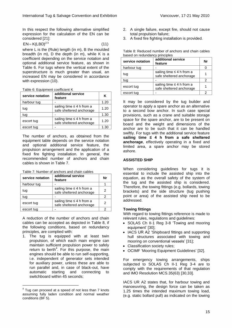
In this respect the following alternative simplified expression for the calculation of the EN can be considered [21]:
32)LBD(KEN (11)
where L is the (Rule) length (in m), B the moulded breadth (in m), D the depth (in m), while K is a coefficient depending on the service notation and optional additional service feature, as shown in Table 6. For tugs where the vertical extent of the superstructure is much greater than usual, an increased EN may be considered in accordance with expression (10). Table 6: Equipment coefficient K
service notation additional service feature
K
harbour tug - 1.20
tug sailing time ≤ 4 h from a safe sheltered anchorage
1.20
tug - 1.30
escort tug sailing time ≤ 4 h from a safe sheltered anchorage
1.20
escort tug - 1.30
The number of anchors, as obtained from the equipment table depends on the service notation and optional additional service feature, the propulsion arrangement and the application of a fixed fire fighting installation. In general, the recommended number of anchors and chain cables is shown in Table 7. Table 7: Number of anchors and chain cables
service notation additional service feature
Nr
harbour tug - 1
tug sailing time ≤ 4 h from a safe sheltered anchorage
2
tug - 2
escort tug sailing time ≤ 4 h from a safe sheltered anchorage
2
escort tug - 2
A reduction of the number of anchors and chain cables can be accepted as depicted in Table 8, if the following conditions, based on redundancy principles, are complied with: 1. The tug is equipped with at least twin
propulsion, of which each main engine can maintain sufficient propulsion power to safely return to berth
4. For this purpose, the main
engines should be able to run self-supporting, i.e. independent of generator sets intended for auxiliary power, unless these are able to run parallel and, in case of black-out, have automatic starting and connecting to switchboard within 45 seconds;
4 Tug can proceed at a speed of not less than 7 knots
assuming fully laden condition and normal weather conditions (BF 5).
2. A single failure, except fire, should not cause total propulsion failure;
3. A fixed fire fighting installation is provided. Table 8: Reduced number of anchors and chain cables based on redundancy principles
service notation additional service feature
Nr
harbour tug - 0
tug sailing time ≤ 4 h from a safe sheltered anchorage
1
tug - 2
escort tug sailing time ≤ 4 h from a safe sheltered anchorage
1
escort tug - 2
It may be considered by the tug builder and operator to apply a spare anchor as an alternative to a second bow anchor. In such case special provisions, such as a crane and suitable storage space for the spare anchor, are to be present on board and the weight and dimensions of the anchor are to be such that it can be handled swiftly. For tugs with the additional service feature sailing time ≤ 4 h from a safe sheltered anchorage, effectively operating in a fixed and limited area, a spare anchor may be stored ashore. ASSISTED SHIP When considering guidelines for tugs it is essential to include the assisted ship into the equation, as the overall safety of the system of the tug and the assisted ship is considered. Therefore, the towing fittings (e.g. bollards, towing brackets) and the side structure (tug pushing point or area) of the assisted ship need to be addressed. Towing fittings
With regard to towing fittings reference is made to relevant rules, regulations and guidelines:
SOLAS Ch II-1 Reg 3-8 ‘Towing and mooring equipment’ [30];
IACS UR A2 ‘Shipboard fittings and supporting hull structures associated with towing and mooring on conventional vessels’ [31];
Classification society rules;
OCIMF ‘Mooring Equipment Guidelines’ [32]. For emergency towing arrangements, ships subjected to SOLAS Ch II-1 Reg 3-4 are to comply with the requirements of that regulation and IMO Resolution MCS.35(63) [30,33]. IACS UR A2 states that, for harbour towing and manoeuvring, the design force can be taken as 1.25 times the intended maximum towing load, (e.g. static bollard pull) as indicated on the towing

International Tug & Salvage Convention and Exhibition Vancouver, 17-21 May 2010
16
and mooring arrangements plan [31]. As the Safe Working Load (SWL) of the towing fittings is not to exceed 80 per cent of this design load, the maximum SWL is 1.05 times the intended maximum towing load. If the maximum intended maximum towing load is considered to correspond to the static bollard pull of the assisting tug, the SWL is consequently 1.05 times the tug’s static bollard pull. For escort operations UR A2 defines the design load as equal to the nominal breaking load of the towline according to the IACS Rec. No. 10 ‘Equipment’ for the ship’s corresponding Equipment Number (EN) [31]. The associated SWL is to be less than the design load. In other words, the maximum SWL is equal to the nominal breaking load of the towline. Permissible stress levels consistent with this approach are provided section A.2.1.6 of the unified requirement. It is to be noted that, based on the findings within the SafeTug JIP as referred to in this paper, careful consideration needs to be given to the application of UR A2, in particular when considering offshore towing and escorting operations
5. For towing operations in waves, due
to dynamic effects, the maximum towline is expected to exceed the maximum (static) bollard pull by more than the 5 per cent considered in the UR A2, in which case a higher SWL of the towing fittings on the assisted ship would be required. For offshore escort operations similar considerations apply with respect to dynamic effects. Moreover, the escort tug master will generally try to maximise the steering and breaking forces and therewith the towline force, using specialised towlines on board the escort tug (which may have a very high nominal breaking strength of up to six times the maximum bollard pull). Therefore, it is of key importance to consider the relationship between the capacity of the tug (maximum towline force) and the strength of the towing fittings on the assisted ship, as design of the towing fittings on the basis if the ship’s EN may lead to insufficient SWL. In case of offshore towing and escort operations, as described in the previous paragraph, it is recommended to consider the design loads for the towing fittings in the same way as the towing equipment and associated supporting structures of the tug. That is, apply the design loads
5 In accordance with IACS UR A1 Sec 1.2, the
equipment is not designed to hold a ship off fully exposed coasts in rough weather or to stop a ship which is moving or drifting. In this condition the loads on the anchoring equipment increase to such a degree that its components may be damaged or lost owing to the high energy forces generated, particularly in large ships [29].
specified in Table 4 for normal towing operations and those of Table 6 for escort towing operations. Application of the permissible stress limits given in expression (8) then provides a consistent approach for towing fittings. Side structure
To ensure the integrity of the assisted ship side structure during pushing operations, it is necessary that the pushing forces exerted by the tug loads are applied on a locally reinforced side structure (towing push point or area) and that the maximum applied pressure by the tug on the assisted ship side structure is to be less than the design load for that part of the structure. The reinforced areas of the assisted ship side should be designed to take in account tug motions, see also the section Towing equipment on fendering. In addition, the tug pushing areas should be clearly marked. The strength characteristics of the assisted ship side structure (maximum pushing force and pressure) should be communicated between the tug and the assisted ship. It is to be noted that the strength of the tug pushing areas is not a class requirement. However, if design forces and/or pressures are specified for new ships in the building specification, the classification society can, if requested, check that the structure is acceptable for the specified pushing loads. SAFETY MANAGEMENT
In accordance with Ch IX Reg 2.1.3 of the SOLAS Convention, the International Safety Management (ISM) Code is applicable to tugs of 500 gt and upwards [34,35]. To this end implementation guidance is available to ship owners and managers [36]. As the implementation of a safety management system is considered to have the potential to increase the safety of ship operations, it is considered within the scope of the harmonisation project to propose requirements for the assignment of a voluntary additional class notation SAFMAN, covering safety management of tugs of less than 500 gt. The purpose of the notation is to provide guidance for the safe management and operation of tugs. Recognizing that no two tug owners or managers are the same, and that tugs operate under a wide range of different conditions, the notation is based on general principles and objectives. The Notation is expressed in broad terms so that it can have a widespread application. Clearly, different levels of management, whether shore-based or at sea, will

International Tug & Salvage Convention and Exhibition Vancouver, 17-21 May 2010
17
require varying levels of knowledge and awareness of the items outlined. The cornerstone of good safety management is commitment from the top management of the company. In matters of safety it is the commitment, competence, attitudes and motivation of individuals at all levels that determines the end result. The objectives of the guidelines are to ensure safety on board of the tug during operations (mobilising, demobilising, towage), as well as the interaction with the towed object, taking into account the navigational area and its limitations. Safety management objectives of the company should, inter alia: 1. Provide for safe practices in tug operation and
a safe working environment; 2. Establish safeguards against all identified
risks; 3. Continuously improve safety management
skills of personnel ashore and aboard tugs, including preparing for emergencies related both to safety and environmental protection.
The safety management system should ensure: 1. Compliance with mandatory rules and
regulations; 2. That applicable Guidance, guidelines and
standards recommended by the organization, administrations, classification societies and maritime industry organizations are taken into account.
Every company should develop, implement and maintain a safety management system which includes the following functional requirements: 1. Instructions and procedures to ensure safe
operation of tugs in compliance with relevant international and flag state legislation;
2. Defined levels of authority and lines of communication between, and amongst, shore and tug board personnel, tug personnel and pilot, tug personnel and crew on board the towed object;
3. Procedures for reporting accidents and non-conformities with the provisions of this Guidance;
4. Procedures to prepare for and respond to emergency situations;
5. Procedures for internal audits and management reviews.
The company should establish a safety policy which describes how the given (safety) objectives will be achieved and should ensure that the policy is implemented and maintained at all levels of the organization, both tug-based and shore-based. Within the scope of the SAFMAN notation, the
following points are addressed in the guidelines:
Responsibilities and authorities, designated persons, as well as resources and personnel;
Development of plans for tug-board operations;
Maintenance of tug and equipment;
Emergency preparedness;
Reporting and documentation;
Company verification, review and evaluation;
Certification and verification. CLOSURE The harmonisation project for safety related class rules for tugs is carried within the scope of the SafeTug II JIP. This enables the participating class societies, Bureau Veritas, Lloyd’s Register of Shipping and American Bureau of Shipping, to directly engage with tug owners/operators, designers/shipyards, research institutes and equipment manufacturers to make use of the available knowledge and experience. This has lead to the drafting of harmonised guidelines for the design and construction of tugs, including escort tugs. Key safety related issues have been addressed and guidelines and recommendations have been proposed, in particular with regard to the definition of design loads, towing and escort stability, towing equipment and safety equipment. With respect to stability further research is recommended to investigate the maximum overturning moment under tug-induced tripping for modern tug designs, as well as the relationship between escort simulations and full scale measurements. In addition, a link has been laid to the assisted ship, as it is considered that the overall safety of tug and assisted ship needs to be addressed. Finally, a proposal has been made for the voluntary implementation of a safety management system for tugs of less than 500 gt, aiming at further enhancing the safety of towing operations on board tugs as well as the assisted ship. Following further discussions and feedback rounds with the participants in the SafeTug II JIP during and after ITS 2010, the guidelines are expected to be finalised during the summer of 2010. Upon completion the document will be submitted to IACS to seek broad support for the issuance of harmonised safety requirements for tugs, which would provide the necessary regulatory framework to the highly dynamic and fast developing tug industry.
International Tug & Salvage Convention and Exhibition Vancouver, 17-21 May 2010
18
REFERENCES
1. Faber G, Sapin J, ‘The Foss Hybrid Tug:
From Innovation to Implementation’, 20th
International Tug & Salvage Convention & Exhibition, Singapore, 19-23 May 2008
2. Wijsmuller, M, ‘How Green Can You Make a Tug?’, 20
th International Tug & Salvage
Convention and Exhibition, Singapore, 19-23 May 2008
3. De Jong G, Corrignan Ph, ‘Guidelines for the safe application of fuel cell systems on ships’, Annual Marine Propulsion Conference, London, 11-12 March 2009
4. Botke FJ, Mathôt LJ, et al, ‘E3 Tug
Development: Economically viable, Environmentally friendly, Efficient in operation’, Tugnology ‘09, Amsterdam, 19-20 May 2009
5. Allan RG, ‘A Proposal for Harmonised International Regulations for the Design and Construction of Tugboats’, 19
th International
Tug & Salvage Convention & Exhibition, Rotterdam, 24-28 April 2006
6. De Jong JH, ‘Ship Assist in Fully Exposed Conditions - Joint Industry Project SafeTug’, Tugnology ’07, Southampton, 11-12 June 2007
7. Buchner B, Dierx P, Waals OJ, ‘The Behaviour of Tugs in Waves assisting LNG Carriers during Berthing along Offshore LNG Terminals’, OMAE 2005, Halkidiki, 12-17 June 2005
8. Buchner B, ‘Understanding Tug Behaviour in Waves and its Consequences’, Business Briefing, LNG Review 2005
9. Storch RL, ‘Stability of Offshore Tugboats’, Marine Technology, October 1972
10. USCG, ‘Navigation and Vessel Inspection circular’, No. 12-83, 1983
11. Roach, CD, ‘Tugboat Design’, Transactions, SNAME, 1955
12. Bureau Veritas, ‘Rules for the Classification of Steel Ships’, NR 467, Pt D, Ch 14, Sec 2, January 2010
13. American Bureau of Shipping, ‘Rules for Building and Classing Steel Vessels under 90 meters (295 feet) in Length’, Pt 5, Ch 8, Sec 2, 2006
14. IACS, ‘Intact Stability’, Rec. No. 24, Rev. 5, May 2005
15. USCG, ‘Special Rules Pertaining to Vessel Use’, Title 46, CFR 173.095, 2005
16. USCG, ‘Towline Pull Criteria for Vessels Equipped with Z-Drives’, Marine Technical Note 01-01, 17 September 2001
17. MARIN, ‘Tests on the ultimate stability of an azimuthing stern drive tug’, Report No. 17910-8-SMB, September 2006 (SafeTug JIP)
18. Rahola J, ‘The Judging of the Stability and the Determination of the Minimum Amount of Stability’, Helsinki, 1939
19. IMO, ‘International Convention on Load Lines, 1966, and Protocol of 1988, as amended in 2003, Consolidated edition, 2005
20. Det Norske Veritas, ‘DNV Rules for Ships’, Pt 5, Ch 7, Sec 15, January 2009
21. Bureau Veritas, ‘Rules for the Classification of Steel Ships’, NR 467, Pt D, Ch 14, Sec 2, January 2010
22. Bureau Veritas, ‘Rules on Materials and Welding for the Classification of Marine Units’, NR 216, October 2008
23. IMO, ‘Guidelines for Safe Ocean Towing’, MSC.Circ/884, 21 December 1998
24. Bureau Veritas, ‘Rules for the Classification of Steel Ships, NR 467’, Pt B, Ch 4, Sec 1, January 2010
25. Norwegian Maritime Directorate, ‘Guidelines on the implementation of specific measures to ensure a sufficient safety level during anchor handling (AH) operations carried out by supply ships or tugs’, RSV 04-2008, 14 July 2008
26. IACS, ‘Recommendations for the Safety of Cargo Vessels of less than Convention Size’, Rec. No. 99, December 2007
27. IMO, ‘Guidelines on alternative design and arrangements for fire safety’, MSC.1/Circ/1002, 26 June 2001
28. IMO, ‘Guidelines on alternative design and arrangements for fire safety’, MSC.1/Circ/1002/Corr/1, 5 October 2005
29. IACS, ‘Equipment’, UR A1, Rev. 5, June 2005 30. IMO, ‘Consolidated text of the International
Convention for the Safety of Life at Sea, 1974, and its protocol of 1988, incorporating all amendments in effect from 1 January 2009’, Consolidated Edition, 2009
31. IACS, ‘Shipboard Fittings and Supporting Hull Structures Associated with Towing and Mooring on Conventional Vessels’, UR A2, Rev. 3, July 2007
32. OCIMF, ’Mooring Equipment Guidelines’, Edition 3, 1 October 2008
33. IMO, ‘Adoption of Guidelines for Emergency Towing Arrangements on Tankers’, MSC.35(63), 20 May 1994
34. IMO, ‘International Management Code for the Safe Operation of Ships and for Pollution Prevention’, A.741(18), 4 November 1993
35. IMO, ‘2000 amendments to the ISM Code’, MSC.104(73), 5 December 2000
36. IMO, ‘Revised guidelines on implementation of ISM Code by Administrations’, A.913(22), 29 November 2001

International Tug & Salvage Convention and Exhibition Vancouver, 17-21 May 2010
19
APPENDIX
Table A1: Safety Matrix – Fire Safety service notation tug, escort tug tug, escort tug harbour tug
additional service feature > 4 h from port or
safe sheltered area 4 h from port or
safe sheltered area (in port)
fire pumps
≥ 150 gt
independently driven power pumps 1 1 1
power pumps 1 1 -
hand pumps - - 1
< 150 gt
independently driven power pumps - - -
power pumps 1 1 1
hand pumps 1 1 -
portable or fixed emergency fire pump 1 1 -
fire hydrants
≥ 150 gt
Sufficient number and so located that at least the number of powerful water jets can reach any normally accessible part of ship
2 2 2
< 150 gt
Sufficient number and so located that at least the number of powerful water jets can reach any normally accessible part of ship
1 1 1
fire hoses (length1)
number of hydrants + 1 spare hose
number of hydrants + 1 spare hose
number of hydrants + 1 spare hose
with coupling and nozzles X X X
hose nozzles
dual purpose (spray/jet) with 12 mm jet and integral shut-off; jet may be reduced to 10 mm and shut-off omitted for hand pump hoses
X X X
portable fire extinguishers
machinery spaces (one extinguisher per 375 kW of internal combustion engine power
2 (capacity 45 l fluid or equivalent)
≥ 2 / 6 ≥ 2 / 6 ≥ 2 / 6
fixed fire extinguishing systems
≥ 150 gt
Category A machinery spaces X X -
Cargo pump rooms X X -
fixed fire detection system (Category A spaces) X X X
fireman’s outfit
complete outfit ≥ 1 ≥ 1 -
fireman’s axe 1 1 1
≥ 150 gt
fire control plan 1 1 1
means of escape
accommodation and service spaces 2 2 2
machinery spaces3 2 2 2
structural fire protection in wheelhouse and machinery spaces
separation from adjacent spaces of negligible fire risk A-0 A-0 A-0
separation from other adjacent spaces A-60 A-30 A-0
Escape routes B-0 B-0 B-0
Notes: (1) Sufficient in length to project a jet of water to any of the spaces in which they may be required to be used (2) Alternatives may be proposed taking into consideration the size of vessel and the installed power (3) Unless when the small size of the machinery space makes it unpractical

International Tug & Salvage Convention and Exhibition Vancouver, 17-21 May 2010
20
Table A2: Safety Matrix – Life Saving Appliances (LSA) service notation tug, escort tug tug, escort tug harbour tug
additional service feature > 4 h from port or
safe sheltered area 4 h from port or
safe sheltered area (in port)
life rafts
100% capacity on each side / easy side to side transfer or 150% capacity on each side
X X (1)
hydrostatic releases X X (1)
Illumination and operating instructions X X (1)
MOB arrangement
rescue boat X(2)
X(2)
-
Jason’s cradle X X X
search light X X X
lifebuoys
with smoke/light 2 1 1
with light 1 1 1
with lifeline 1 1 1
lifejackets with lights
each person on board X X X
immersion suit
each person on board X X -
other equipment
rocket parachute flares 12 6 -
red hand flares 6 2 2
smoke signals 2 buoyant 2 2
line throwing apparatus 1 1 -
general alarm X X X
communication system
to engine room / accommodation / deck X X X
documentation on board
fire and safety plan X X X
training and instruction manual X X X
SOLAS life saving table X X X
muster list and emergency instructions X X X
Notes: (1) A float free buoyant apparatus is to be provided (2) The ships’ operational working area, manoeuvrability, size, freeboard and propulsion arrangement may be taken into considerat ion
for the evaluation of the applicability of the requirement for a rescue boat
Table A3: Safety Matrix – Radio Installation service notation tug, escort tug tug, escort tug harbour tug
additional service feature > 4 h from port or
safe sheltered area 4 h from port or
safe sheltered area (in port)
general requirements
≥ 300 gt
SOLAS (A1+A2+A3+A4, as applicable) X X X
< 300 gt
no duplication of equipment required X X X
specific requirements
VHF / DSC 1 1 1
SART(1)
1 1 1
EPIRB / satellite 1 1 (A2+A3) -
EPIRB / VHF - 1 (A1) -
NAVTEX 1 1 -
MF / DSC 1 - (2)
-
INMARSAT C 1 - (2)
-
GMDSS porto 1 1 1
electrical power supply dedicated radio
battery emergency battery emergency battery
Notes: (1) SART is not required if the 406 MHZ EPIRB provided has a 121.5 MHz frequency transmitting capability and is of the non-float
free type for placing in a life raft (2) MF / DSC or INMARSAT C depending on region

International Tug & Salvage Convention and Exhibition Vancouver, 17-21 May 2010
21
Table A4: Safety Matrix – Navigation Equipment service notation tug, escort tug tug, escort tug harbour tug
additional service feature > 4 h from port or
safe sheltered area 4 h from port or
safe sheltered area (in port)
general requirements
SOLAS Ch V is to be taken into account for all ships on all voyages the administration shall determine to what extent the provisions of SOLAS Ch V do not apply to the following ships:
tugs below 150 gt on any voyage
tugs below 150 gt not engaged on international voyages(1)
X X X
specific requirements
radar 1 1 -
magnetic compass
1(2)
1(2)
1
gyro compass 1(2)
1(2)
-
GPS compass 1(2)
1(2)
-
GPS 2 1 1
AIS 1 1
1
nautical charts / ECDIS 1 1 1
daylight signalling lamp 1 1 1
echo sounding 1 1 1
IAMSAR 1 1 1
code of signals 1 1 1
Notes: (1) International voyage: voyage from a country to which the SOLAS Convention applies to a port outside such country, or conversely (2) Optional 2 out of 3