the bulging intensity factor (bif) - hes.us.com bulging intensity factor (bif) ... designed per...
TRANSCRIPT

The Bulging Intensity Factor (BIF) A technique for assessing the bulging severity of coke drums
Mahmod Samman, Ph.D., P.E.
Senior Associate Stress Engineering Services
Houston, Texas [email protected]
Pierre Du Plessis Mechanical Engineering Manager
Sustaining Projects, Suncor Energy Fort McMurray, Canada
Abstract - Bulging is the non-uniform radial growth of pressure vessels that can result from cyclic mechanical or thermal loads. It is a common problem in coke drums that can lead to cracking, product leakage, and fires. The Bulging Intensity Factor (BIF) is a fitness-for-service technique for the evaluation of coke drum bulging. The method uses a pattern recognition approach that works by analyzing the similarity between three-dimensional surface bulging patterns of a given drum and ones associated with known cracking histories. The BIF is used to identify and rank the areas of the drum that are most susceptible to cracking from the increased cyclic stress induced by the bulge geometry. In this paper, the background and applicability of the technique are discussed along with an operator’s experience in using it for the integrity management of a large set of coke drums.
This paper is dedicated to the memory of Tom D. Farraro for his leadership and numerous contributions to coke drum engineering.
INTRODUCTION There are about fifty five Delayed Coker Units (DCU) in operation in the United States, in about one third of all refineries. A DCU is a refinery component that is used to fractionate heavy oil residues into lighter fluids. The semi-batch process includes severe thermal cracking that produces solid coke and higher-value products.
Coke drums are the large vertical pressure vessels that are used for the batch side of the DCU process. Their size varies from 15 to 30 feet in diameter and from 55 to 90 feet in height. Their metallurgy is typically Carbon Steel, C-½Mo, or Cr-Mo alloys. They are usually designed per ASME’s Boiler and Pressure Vessel Code, Section VIII Division 1.
The cracking process exposes these vessels to unusually harsh thermal and mechanical conditions during their normal cyclic operation. Since these severe cyclic loads are not accounted for in the design process most drums as they age develop permanent plastic deformations and experience various failure mechanisms.
The failure mechanisms that are experienced by coke drums have long been identified, investigated, and documented. Weil and Rapasky (1958) published one of the earliest and most comprehensive discussions of coke drum failure modes. In this widely-referenced paper, they identified the following eight common failure modes: Deformation and growth of shell, irregular local warping of shell, cracking of skirt attachment weld,
RMC-07-100 National Petrochemical & Refiners Association Page 1 2007 NPRA Reliability & Maintenance Conf.

distortion of bottom manhole-neck flange, weld cracking between bottom cone and manhole neck, nozzle attachment cracking, and dishing of bottom cover.
The first one in the Weil and Rapasky list of common failure modes continues to be the most common and potentially the most serious one. The deformation and growth of the shell is manifested in several forms: radial growth, ovalization, and leaning (tilting). Radial growth is the one that is more likely to cause cracks, leaks, fires, operation delays, and potentially catastrophic accidents.
BULGING SEVERITY Bulging is the non-uniform radial growth of the cylindrical section of coke drums. One of the significant advances in coke drum inspection and maintenance that took place in the 1990s is the advent of internal laser scanning of drums. (Clark et al., 1995) This technology has made possible the timely automated global measurement and long-term monitoring of bulging magnitude. In a relatively short time, this tool has now become a standard procedure in coke drum maintenance.
Laser scanning gave us an insight into the complex geometric patterns of a bulging drum. Figure 1 shows a three-dimensional view of a laser-scanned drum that is unrolled into a surface. To demonstrate the underlying features of the surface, the figure exaggerates radial growth in comparison with the height and azimuth coordinates. As the figure shows, in addition to local peaks and valleys, there are geometric shapes that look like wrinkles, ridges and canyons.
The nature and cause of radial growth are beyond the scope of this paper. What is relevant here is that bulging accelerates the formation and propagation of cracks that can cause leaks and fires. So, from a maintenance standpoint, it is critical to:
1. Assess the severity of bulging in a given drum and its likelihood of cracking inducement, and
2. Rank the specific areas of the drum that require more detailed inspection.
Stresses that initiate and propagate cracks are a function of two components:
a) The nominal membrane and bending stress at the wall surface, and
b) Localized stress concentrations that amplify nominal stresses such as weld defects, voids, undercuts, notches, and lack-of-fusion.
Nominal axial bending and hoop membrane stresses substantially increase due to bulging. Figure 2 shows the results of analyzing a measured bulging profile (shown in pink at the bottom of the graphs) of a coke drum under operating pressure. The finite element model uses axisymmetric elements which assume that the bulging profile is uniform around the axis of the drum. The figure shows that hoop and axial stresses are more than quadruple those of a perfectly cylindrical drum. The figure also suggests that, if the probability of a stress riser is evenly distributed over the drum surface, cracking will likely occur at the points of maximum bulging on the inside or outside of the wall.
While the above stress profiles are significant in illustrating the dramatic influence of bulges on nominal stresses in coke drums, such conventional pressure-loaded finite element models can’t be used to assess bulging severity in operating drums. After many attempts to compare stress results of such simplified models with known cracking histories, it appeared that no particular stress component or equivalent stress value can be correlated to actual cracking history. There are two basic reasons for that:
(1) The loading applied on coke drums is significantly more
RMC-07-100 National Petrochemical & Refiners Association Page 2 2007 NPRA Reliability & Maintenance Conf.

complex than simple pressure loads. Field measurements and detailed finite element analyses of coke drums have shown that in most cases the cyclic stress in the shell is primarily driven by thermal transients during the fill side of the cycle and by shell-coke interaction during the quench side. (Farraro and Boswell, 1996; Boswell et al., 1997; Boswell and Farraro, 1998) Quench loading is further complicated by the random and non-uniform water channeling inside the hardened coke and the uneven cooling of the drum which causes hard-to-predict but potentially severe localized thermal gradients in the shell.
(2) The three-dimensional pattern of bulging makes the analysis far too complex for a simplified model to resolve. This is especially true in the way a bulged drum interacts with solid coke inside.
In summary, bulging is detrimental to the structural integrity of coke drums. Their presence initiates an accelerated cyclic stress leading to economic end of life. The three-dimensional nature of bulging patterns and their complex interaction with the various loading mechanisms in coke drums make the assessment of bulging severity a challenging task for conventional stress analysis techniques. Because of the above, there is a need for a simplified methodology that can be used for assessing bulging severity in coke drums.
THE BULGING INTENSITY FACTOR (BIF) Pattern recognition (PR) is the science of understanding and mimicking human identification of images, shapes, and waveforms using computers. This technology has been used for decades in various applications such as computer vision, character recognition, geographical
terrain feature identification, and image processing. Waveform recognition is the subclass of PR that deals with interpretation of single-valued functions in such applications as speaker identification, medical signal diagnostics, and machinery monitoring. In the 1990s, waveform recognition was successfully used for the interpretation of digital signals in several structural damage detection applications. (Samman, 1990; Samman et al., 1991; Biswas et al., 1994; Samman and Biswas, 1994-Iⅈ Samman, 1998; Samman, 2001)
Waveform recognition techniques are heuristic methods that work by trial-and-error. The more examples used to “train” these tools the more accurate they get. The strength of these techniques is that they can analyze relatively complex problems in a timely manner and in the presence uncertainties in the underlying data. Their main shortcoming is that the accuracy of the recognition process is a function of the number and quality of training examples.
The Bulging Intensity Factor (BIF) is a waveform recognition technique that was developed by Stress Engineering Services to analyze bulging patterns and determine their severity and likelihood of cracking. To develop the technique, a database of scanned drums with known bulging-related cracking histories was collected and analyzed. Then the geometric features associated with crack locations were analyzed using available waveform recognition techniques. At the end, a procedure that includes bi-axial frequency, magnitude, and curvature processing was found to be consistent in identifying the geometric features associated with cracking history. As described later in this paper, when the BIF was used to analyze a new set of scans with no known cracking, the technique was successful in assessing the severity of bulging and suggesting the locations of future cracks.
RMC-07-100 National Petrochemical & Refiners Association Page 3 2007 NPRA Reliability & Maintenance Conf.
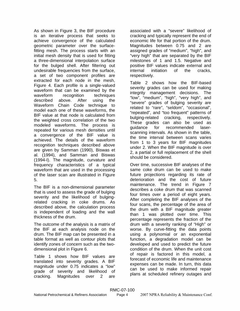
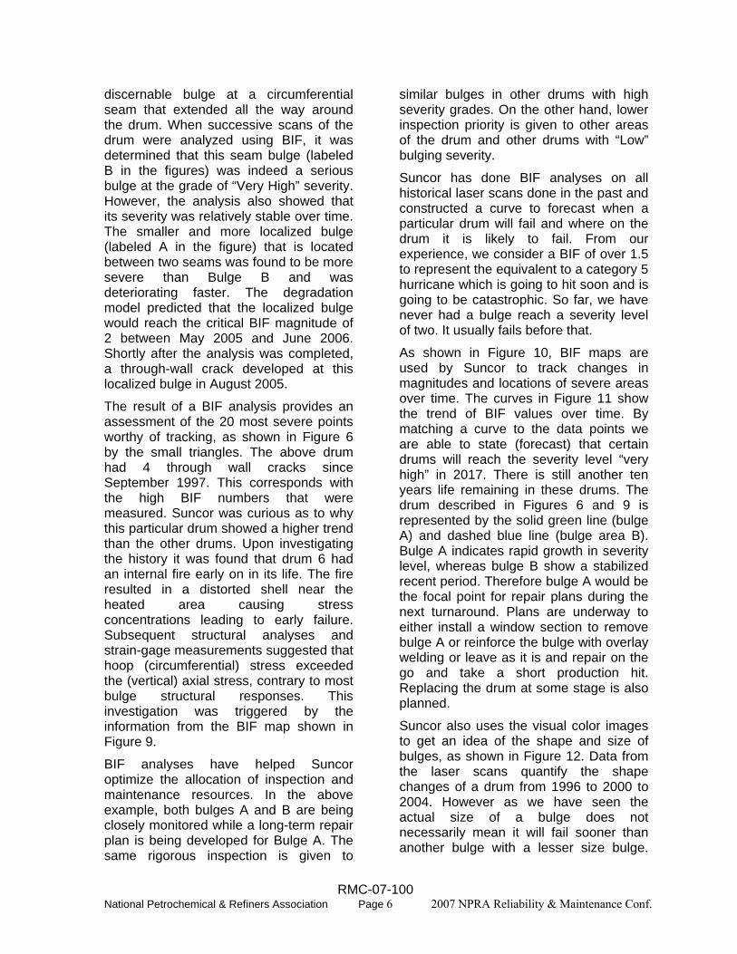
As shown in Figure 3, the BIF procedure is an iterative process that seeks to achieve convergence of the calculated geometric parameter over the surface-fitting mesh. The process starts with an initial mesh density that is used for fitting a three-dimensional interpolation surface for the bulged shell. After filtering out undesirable frequencies from the surface, a set of two component profiles are extracted for each node in the mesh, Figure 4. Each profile is a single-valued waveform that can be examined by the waveform recognition techniques described above. After using the Waveform Chain Code technique to model each one of these waveforms, the BIF value at that node is calculated from the weighted cross correlation of the two modeled waveforms. The process is repeated for various mesh densities until a convergence of the BIF value is achieved. The details of the waveform recognition techniques described above are given by Samman (1990), Biswas et al. (1994), and Samman and Biswas (1994-I). The magnitude, curvature and frequency characteristics of a typical waveform that are used in the processing of the laser scan are illustrated in Figure 5.
The BIF is a non-dimensional parameter that is used to assess the grade of bulging severity and the likelihood of bulging-related cracking in coke drums. As described above, the calculation process is independent of loading and the wall thickness of the drum.
The outcome of the analysis is a matrix of the BIF at each analysis node on the drum. The BIF map can be presented in a table format as well as contour plots that identify zones of concern such as the two-dimensional plot in Figure 6.
Table 1 shows how BIF values are translated into severity grades. A BIF magnitude under 0.75 indicates a “low” grade of severity and likelihood of cracking. Magnitudes over 2 are
associated with a “severe” likelihood of cracking and typically represent the end of economic life for that portion of the drum. Magnitudes between 0.75 and 2 are assigned grades of “medium”, “high”, and “very high” that are separated by the BIF milestones of 1 and 1.5. Negative and positive BIF values indicate external and internal initiation of the cracks, respectively.
Table 2 shows how the BIF-based severity grades can be used for making integrity management decisions. The “low”, “medium”, “high”, “very high”, and “severe” grades of bulging severity are related to “rare”, “seldom”, “occasional”, “repeated”, and “too frequent” patterns of bulging-related cracking, respectively. These grades can also be used as guidance for recommended laser-scanning intervals. As shown in the table, the time interval between scans varies from 1 to 3 years for BIF magnitudes under 2. When the BIF magnitude is over 2, a partial or full replacement of the shell should be considered.
Over time, successive BIF analyses of the same coke drum can be used to make future projections regarding its rate of deterioration and the cost of future maintenance. The trend in Figure 7 describes a coke drum that was scanned four times over a period of eight years. After completing the BIF analyses of the four scans, the percentage of the area of the drum with a BIF magnitude greater than 1 was plotted over time. This percentage represents the fraction of the drum with a severity ranking of “High” or worse. By curve-fitting the data points using a polynomial or an exponential function, a degradation model can be developed and used to predict the future condition of the drum. When the unit cost of repair is factored in this model, a forecast of economic life and maintenance expenses can be made. In turn, this data can be used to make informed repair plans at scheduled refinery outages and
RMC-07-100 National Petrochemical & Refiners Association Page 4 2007 NPRA Reliability & Maintenance Conf.

place timely orders for partial or full replacement of the drum.
FITNESS-FOR-SERVICE IMPLICATIONS The most commonly-used fitness-for-service reference in the refining industry is the American Petroleum Institute’s Recommended Practice of API-579 (2000). In 2007, this document is expected to become a joint standard with the American Society of Mechanical Engineers (ASME).
Paragraph 8.4.3.6 of Section 8 of the first edition of API-579 contains a Level 2 assessment procedure for bulges. This procedure is relatively limited in its scope. For example, axisymmetric bulges and the existence of significant supplemental loads both of which are common in coke drums are not covered by the procedure. For such instances, the document requires the use of more rigorous stress or strain-based Level 3 assessment procedures that are problem-specific.
In the new version of the document (i.e. the 2007 joint API/ASME standard), no bulging assessment procedure is provided.
The above illustrates the difficulty of and the lack of standard procedures for assessing the fitness-for-service of complex bulging mechanisms like those in coke drums. The BIF has been specifically developed to aid in the fitness-for-service assessment of coke drums. The use of this technique outside its intended scope has not been evaluated yet.
SUNCOR’S EXPERIENCE Suncor’s tar sands refinery in Fort McMurray Canada has one of the world’s largest upgrading coking units. The plant contains six drums built in 1966, two in 1979, four in 2001, and eight new ones or pending for a total of 20 drums. They range in diameter from 26 to 32 feet and in height from 66 to 94 feet.
Needless to say, the maintenance and integrity assurance of these drums is a top priority for refinery management. As shown in Figure 8, a comprehensive integrity management approach has been developed using the following techniques:
• Laser scans • Bulging severity analysis using the
Bulging Intensity Factor (BIF) • Finite Element Analysis (FEA) • Probabilistic Crack Propagation
calculations • Strain Gage Measurements • Acoustic Emission Testing (AET)
Specifically, the techniques are intended to answer the following questions:
o How severe is the Bulging in the Drums?
o How should we prioritize the drum inspection needs?
o When will the bulging result in Cracking?
o When should we replace the coke drums?
o How soon do we need to rescan the drum?
o How can we minimize unplanned outages?
o What will be the total crack repair cost 5 to 10 years from now?
As shown in Figure 8, the BIF is an essential part of Suncor’s integrity management process that is utilized for two main purposes. First, it is used for initial screening of drums to determine their bulging severity and the need for any further analysis or testing. Second, successive BIF analyses are used for making future predictions regarding the cost of drums maintenance and the need for and timing of partial or full replacement of the shell.
The two-dimensional BIF contour plot of Figure 6 and the three-dimensional maps shown in Figure 9 belong to one of Suncor’s drums that was experiencing a
RMC-07-100 National Petrochemical & Refiners Association Page 5 2007 NPRA Reliability & Maintenance Conf.
discernable bulge at a circumferential seam that extended all the way around the drum. When successive scans of the drum were analyzed using BIF, it was determined that this seam bulge (labeled B in the figures) was indeed a serious bulge at the grade of “Very High” severity. However, the analysis also showed that its severity was relatively stable over time. The smaller and more localized bulge (labeled A in the figure) that is located between two seams was found to be more severe than Bulge B and was deteriorating faster. The degradation model predicted that the localized bulge would reach the critical BIF magnitude of 2 between May 2005 and June 2006. Shortly after the analysis was completed, a through-wall crack developed at this localized bulge in August 2005.
The result of a BIF analysis provides an assessment of the 20 most severe points worthy of tracking, as shown in Figure 6 by the small triangles. The above drum had 4 through wall cracks since September 1997. This corresponds with the high BIF numbers that were measured. Suncor was curious as to why this particular drum showed a higher trend than the other drums. Upon investigating the history it was found that drum 6 had an internal fire early on in its life. The fire resulted in a distorted shell near the heated area causing stress concentrations leading to early failure. Subsequent structural analyses and strain-gage measurements suggested that hoop (circumferential) stress exceeded the (vertical) axial stress, contrary to most bulge structural responses. This investigation was triggered by the information from the BIF map shown in Figure 9.
BIF analyses have helped Suncor optimize the allocation of inspection and maintenance resources. In the above example, both bulges A and B are being closely monitored while a long-term repair plan is being developed for Bulge A. The same rigorous inspection is given to
similar bulges in other drums with high severity grades. On the other hand, lower inspection priority is given to other areas of the drum and other drums with “Low” bulging severity.
Suncor has done BIF analyses on all historical laser scans done in the past and constructed a curve to forecast when a particular drum will fail and where on the drum it is likely to fail. From our experience, we consider a BIF of over 1.5 to represent the equivalent to a category 5 hurricane which is going to hit soon and is going to be catastrophic. So far, we have never had a bulge reach a severity level of two. It usually fails before that.
As shown in Figure 10, BIF maps are used by Suncor to track changes in magnitudes and locations of severe areas over time. The curves in Figure 11 show the trend of BIF values over time. By matching a curve to the data points we are able to state (forecast) that certain drums will reach the severity level “very high” in 2017. There is still another ten years life remaining in these drums. The drum described in Figures 6 and 9 is represented by the solid green line (bulge A) and dashed blue line (bulge area B). Bulge A indicates rapid growth in severity level, whereas bulge B show a stabilized recent period. Therefore bulge A would be the focal point for repair plans during the next turnaround. Plans are underway to either install a window section to remove bulge A or reinforce the bulge with overlay welding or leave as it is and repair on the go and take a short production hit. Replacing the drum at some stage is also planned.
Suncor also uses the visual color images to get an idea of the shape and size of bulges, as shown in Figure 12. Data from the laser scans quantify the shape changes of a drum from 1996 to 2000 to 2004. However as we have seen the actual size of a bulge does not necessarily mean it will fail sooner than another bulge with a lesser size bulge.
RMC-07-100 National Petrochemical & Refiners Association Page 6 2007 NPRA Reliability & Maintenance Conf.

The BIF number is found to be a much more reliable indicator of when a drum will fail. Out of 6 drums that have been operating since 1967, two have had cracks and four have never cracked. They are operated by the same crews and under the same conditions and see the same product. The fact that some drums crack, could easily lead plant personnel to panic and start a program of drum replacement which is very costly. However, the BIF “measurement” has given us the insight and confidence that the drum life is predictable and that we can plan accordingly.
Suncor has now introduced a program of two yearly laser scans and subsequent BIF analysis. We update our remaining life forecast accordingly.
In summary, Suncor uses the BIF along with other available tools to examine the structural integrity of coke drums and make future predictions of inspection needs and projected life. Suncor’s experience shows that the technique correlates well with actual cracking history.
CONCLUSIONS The Bulging Intensity Factor (BIF) is a method for analyzing bulging severity in coke drums. It is a geometric function that combines several physical properties like frequency, magnitude, and curvature into one number. The technique has been used to analyze over 30 coke drums with a variety of metallurgies and sizes. To date, the results have correlated well with cracking history.
ACKNOWLEDGMENTS The authors recognize the valuable contributions of many engineers who have assisted in the analysis and review of the material presented in this paper. Special thanks to Mr. Vrajesh Shah, to Mr. Charles Stephens and Mr. Aaron Johnson
of Suncor, and to Mr. Richard S. Boswell, P.E of Stress Engineering Services, Inc.
REFERENCES American Petroleum Institute (2000) Fitness For Service, Recommended Practice 579, First Edition.
Biswas, M., Samman, M., Pandey, A. K., and Bluni, S. A. (1994). "Modified Chain Code Computer Vision Techniques for Interrogation of Vibration Signatures for Structural Fault Detection", Journal of Sound and Vibration, Academic Press, 175(1) 89-104.
Boswell, R. and Farraro, T. (1998) “Method of Designing and Manufacturing a Delayed Coker Drum”, U.S. Patent 5,827,403.
Boswell, R. S. Farraro, T., and Sober, M. J. (1997) “Remaining Life Evaluation of Coke Drums” Energy Engineering Conference, Plant Engineering, Operations, Design, and Reliability Symposium, ASME.
Clark, R., Boswell, R. S., and Farraro, T. (1995) “State of the Art Coke Drum Inspection and Analysis” API Fall Meeting, Subcommittee on Coke Drum Inspection.
Farraro, T. and Boswell, R.S. (1996) “Determination of Coke Drum Fitness-for-Service and Remaining Life” API Spring Meeting, Operating Practices Symposium.
Samman, M. (2001) "A hybrid analysis method for vibration signals based on neural networks and pattern recognition techniques." Journal of Vibration and Acoustics, American Society of Mechanical Engineers, 123(1) 122-124.
Samman, M. (1998) "Interpretation of Digital Signals Using Hybrid Neural Networks and Pattern Recognition Techniques." Chapter 5 in Artificial Neural Networks for Civil Engineers: Advanced Features and Applications, edited by Flood, I., and Kartam, N., The American Society of Civil Engineers.
RMC-07-100 National Petrochemical & Refiners Association Page 7 2007 NPRA Reliability & Maintenance Conf.

Samman, M. and Biswas, M. (1994-I). "Dynamic Testing for Nondestructive Evaluation of Bridges. I: Theory", Journal of Structural Engineering, American Society of Civil Engineers, 120(1) 269-289.
Samman, M. and Biswas, M. (1994-II). "Dynamic Testing for Nondestructive Evaluation of Bridges. II: Results", Journal of Structural Engineering, American Society of Civil Engineers, 120(1) 290-306.
Samman, M., Biswas, M., and Pandey, A. K. (1991). "Employing Pattern Recognition for Detecting Cracks in a Bridge Model", International Journal of Analytical and
Experimental Modal Analysis, Society of Experimental Mechanics, 6(1) 35-44.
Samman, M. (1990). Pattern Recognition Methods for Detection of Degradation in Bridge Structures, Ph.D. Dissertation, Department of Civil and Environmental Engineering, Duke University.
Stewart, C. (2004) “Vertical Plate Technology Extends the Life of Coke Drums” Welding Journal, April 34-36.
Weil, N. and Rapasky, F.S. (1958) “Experience with Vessels of Delayed-Coking Units” presented at 23rd Midyear Meeting of API, Division of Refining, 38 (III) 214-232.
Table 1 – The grade of bulging severity versus BIF BIF External Cracking Likelihood Internal Cracking Likelihood≥+2 SEVERE (End of Economic Life)
+1.5 to +2 Very High +1 to +1.5 High +0.75 to +1 Medium 0 to +0.75 Low 0 to -0.75 Low -0.75 to -1 Medium -1 to -1.5 High -1.5 to -2 Very High
≤-2 SEVERE (End of Economic Life)
Table 2 – Integrity management implications of the BIF severity grade Severity Grade Cracking Pattern
Related to Bulging Recommended Laser Scanning Frequency
Low Rare Every 3 years Medium Seldom Every 2 years
High Occasional Every 1 year Very High Repeated Every 1 year SEVERE Too frequent
to operate economicallyConsider partial or full
shell replacement
RMC-07-100 National Petrochemical & Refiners Association Page 8 2007 NPRA Reliability & Maintenance Conf.

Figure 1: Geometric patterns of a bulging coke drum
Hoop Stress Axial Stress
Figure 2: Stress profiles due to axisymmetric bulging
RMC-07-100 National Petrochemical & Refiners Association Page 9 2007 NPRA Reliability & Maintenance Conf.
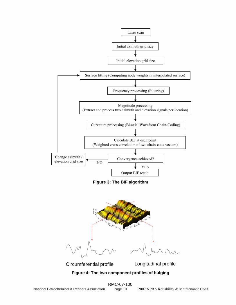
Figure 3: The BIF algorithm
Circumferential profile Longitudinal profile Figure 4: The two component profiles of bulging
Surface fitting (Computing node weights in interpolated surface)
Frequency processing (Filtering)
Curvature processing (Bi-axial Waveform Chain-Coding)
Convergence achieved? Change azimuth / elevation grid size
Laser scan
Output BIF result
Initial azimuth grid size
YES NO
Magnitude processing (Extract and process two azimuth and elevation signals per location)
Initial elevation grid size
Calculate BIF at each point (Weighted cross correlation of two chain-code vectors)
RMC-07-100 National Petrochemical & Refiners Association Page 10 2007 NPRA Reliability & Maintenance Conf.

Magnitude
Curvature
Frequency
Figure 5: The three geometric characteristics of a typical bulging waveform
B
C
D
E
F
A
B
C
D
E
F
A
Figure 6: A two-dimensional BIF map with highlighted severity zones
Time
% o
f she
ll w
ith "
Hig
h" B
IF-s
ever
ity
Cos
t of s
hell
crac
k re
pairs
($)
TIME (years)
% H
igh
seve
rity
Time
% o
f she
ll w
ith "
Hig
h" B
IF-s
ever
ity
Cos
t of s
hell
crac
k re
pairs
($)
TIME (years)
% H
igh
seve
rity
Figure 7: Predictions of deterioration and repair cost using successive BIF analyses
RMC-07-100 National Petrochemical & Refiners Association Page 11 2007 NPRA Reliability & Maintenance Conf.

SESBIF
Bulge Inspection Factor
Strain Gage Shell + Skirt
FEA (Finite element Analysis)
SuncorIn house crack
predictionanalysis
Economic Evaluation
Cold Eyes Review
CIA Laser Scans
Drum RemainingLife
1.1. Search for bulging and evaluate it.Search for bulging and evaluate it.2.2. Search for cracking.Search for cracking.3.3. Determine actual cyclic stress in shell and skirt. Determine actual cyclic stress in shell and skirt. 4.4. Develop Long Term Operation, Inspection, Develop Long Term Operation, Inspection,
Repair and Replacement PlansRepair and Replacement Plans...
AET
Figure 8: Suncor’s approach for remaining life assessment
Maximum BIF (A)
THROUGH WALL CRACK August
2005(B)
Crack away from weld (BIF=1.82)
BIF PREDICTIONS
Bulge A is expected to have a “severe” likelihood of cracking between May 2005 and June 2006
Bulge B- The bulges in shell course #5, is expected to remain stable at the “very high”likelihood of cracking for the next few years
Figure 9: Example of BIF’s bulging assessment and predictions
RMC-07-100 National Petrochemical & Refiners Association Page 12 2007 NPRA Reliability & Maintenance Conf.

Figure 10: Tracking the changes in BIF magnitudes and locations over time
BIF map of 1996 scan
BIF map of 2004 scan
Suncor tracks the progress of the BIF of a certain bulge and predict when it may reach a
critical value (BIF > 1.5)
Figure 11: BIF trend analysis and severity predictions for several drums
RMC-07-100 National Petrochemical & Refiners Association Page 13 2007 NPRA Reliability & Maintenance Conf.

Figure 12: Comparison of laser scans from 1996 to 2000
RMC-07-100 14 2007 NPRA Reliability & Maintenance Conf. National Petrochemical & Refiners Association Page