testing –high speed fiber links - bicsi · fiber optics technology consortium • maintain a...
TRANSCRIPT
TESTING – HIGH SPEED FIBER LINKS
Rodney Casteel, RCDD, DCDC, NTS, OSP - CommScope, Chair TIA FOTCTyler Vander Ploeg, RCDD - Viavi Solutions
Jamie Humphreys - EXFORob Gilberti - AFL
Jim Davis - Fluke Networks
Agenda• Intro to FOTC•Basic/Tier 1 Fiber Certification•Tier-2 OTDR testing & troubleshooting•Short break•A Live demo
Fiber Optics Technology ConsortiumOverview:• Part of the Telecommunications Industry Association
(www.tiaonline.org)Until 2013, we had been known as the Fiber Optics LAN Section (FOLS). Our new name was chosen to reflect our expanding charter.
• Formed 23 years ago• Mission: to educate users about the benefits of deploying fiber in
customer-owned networks• FOTC provides vendor-neutral information
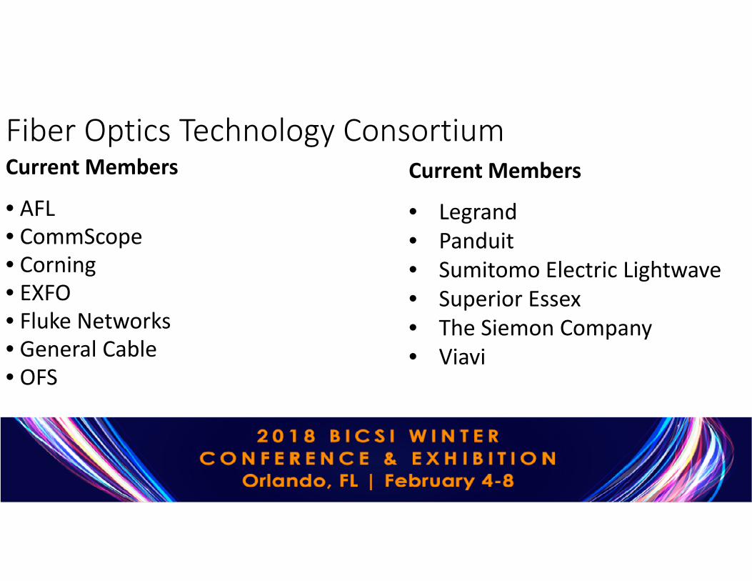
Fiber Optics Technology ConsortiumCurrent Members
• AFL• CommScope• Corning• EXFO• Fluke Networks• General Cable• OFS
Current Members
• Legrand• Panduit• Sumitomo Electric Lightwave• Superior Essex• The Siemon Company• Viavi

Fiber Optics Technology Consortium• Maintain a website with Fiber FAQs, White Papers and other
resources – www.tiafotc.org.• Developed and maintain a free Cost Model that allows users to
compare installed first costs of several architectures.• Host a webinar series throughout the year with all webinars
available on demand.• Speak at industry conferences like BICSI• Contribute to industry publications – Like BICSI News.• Conduct market research – like the surveys today

Fiber Optics Technology Consortium• Recent Webinars Available on Demand
• Keeping up with High Speed Migration in the Data Center• Data Center Design, Planning & Upcoming Changes to TIA-942• Best Practices for Achieving Tier 1 Fiber Certification
• Visit www.tiafotc.org or our channel on BrightTalk
• Webinars are eligible for CEC credit for up to two years after they are first broadcast. Email [email protected] if you have completed a webinar and want to receive your CEC.

Important NoticeAny product(s) identified or identifiable via a trade name or otherwise in this presentation as a product(s) supplied by a
particular supplier(s) is provided for the convenience of users of this presentation and does not constitute an endorsement of any
kind by TIA of the product(s) named. This information may be provided as an example of suitable product(s) available
commercially. Equivalent product(s) may be used if they can be shown to lead to the same results.

Basic/Tier 1 Fiber Certification
Tyler Vander Ploeg, RCDDFiber Solutions Marketing ManagerVIAVI SolutionsOrlando, FL, February 5, 2018

Agenda• Testing Basics
• Standards / Channels and Links / dB vs. dBm• Tier 1 Testing
• Certification Requirements• Main Challenges• Reference methods
• Tier 1 Testing for MPO• Additional Challenges
• Conclusion/Q&A

Testing Basics
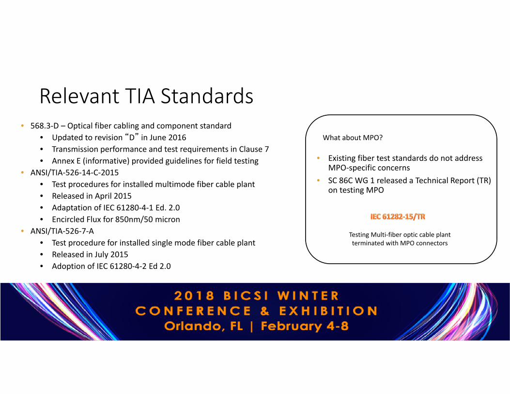
• 568.3-D – Optical fiber cabling and component standard• Updated to revision “D” in June 2016• Transmission performance and test requirements in Clause 7• Annex E (informative) provided guidelines for field testing
• ANSI/TIA-526-14-C-2015• Test procedures for installed multimode fiber cable plant• Released in April 2015• Adaptation of IEC 61280-4-1 Ed. 2.0• Encircled Flux for 850nm/50 micron
• ANSI/TIA-526-7-A• Test procedure for installed single mode fiber cable plant• Released in July 2015• Adoption of IEC 61280-4-2 Ed 2.0
Relevant TIA Standards
• Existing fiber test standards do not address MPO-specific concerns
• SC 86C WG 1 released a Technical Report (TR) on testing MPO
Testing Multi-fiber optic cable plant terminated with MPO connectors
What about MPO?

Tests Defined in Standards
• Both TIA and ISO/IEC standards specify to tiers of certification• Tier 1 (or basic): loss, length, and polarity• Tier 2 (or extended): Optical time domain reflectometer (OTDR)
• Tier 2 (extended) tests are an optional addition to tier 1 (basic) tests
• Fiber end-face inspection and certification is also a requirement to ensure pristine end-face condition PRIOR to mating
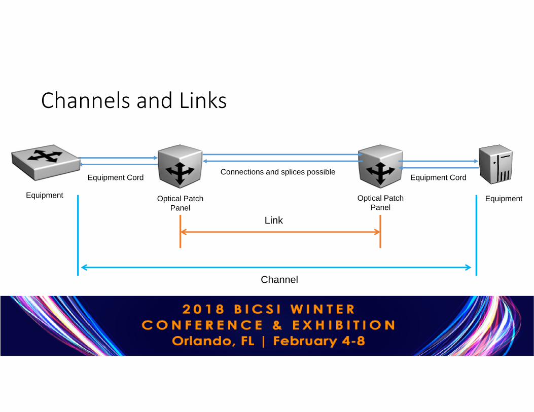
Channels and Links
Optical Patch Panel
Optical Patch Panel
Equipment Equipment
Connections and splices possibleEquipment Cord Equipment Cord
Channel
Link
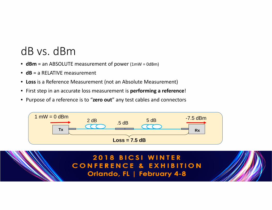
dB vs. dBm• dBm = an ABSOLUTE measurement of power (1mW = 0dBm)
• dB = a RELATIVE measurement• Loss is a Reference Measurement (not an Absolute Measurement)• First step in an accurate loss measurement is performing a reference! • Purpose of a reference is to “zero out” any test cables and connectors
Tx Rx
2 dB 5 dB1 mW = 0 dBm
.5 dB
Loss = 7.5 dB
-7.5 dBm
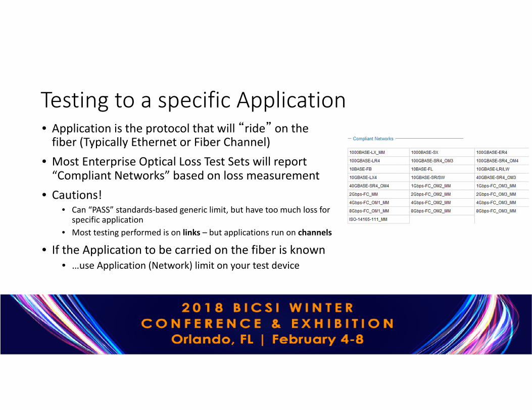
Testing to a specific Application• Application is the protocol that will “ride” on the
fiber (Typically Ethernet or Fiber Channel)• Most Enterprise Optical Loss Test Sets will report
“Compliant Networks” based on loss measurement• Cautions!
• Can “PASS” standards-based generic limit, but have too much loss for specific application
• Most testing performed is on links – but applications run on channels
• If the Application to be carried on the fiber is known• …use Application (Network) limit on your test device

Tier 1 Testing
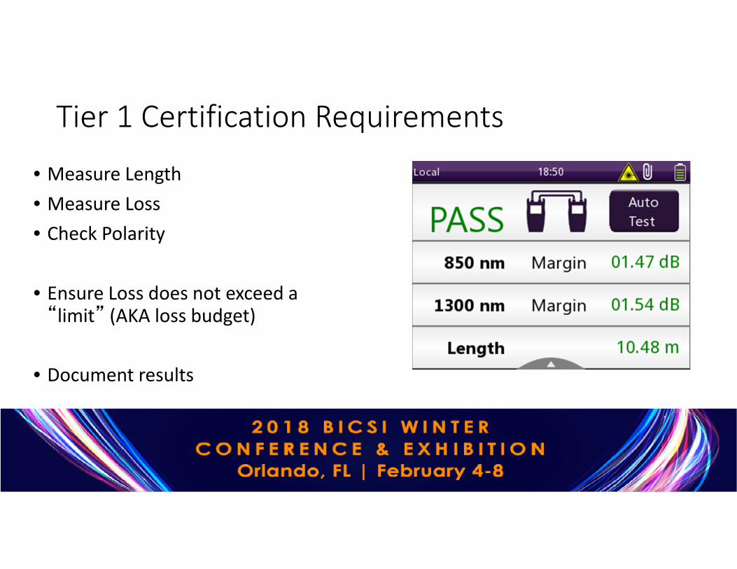
Tier 1 Certification Requirements
• Measure Length• Measure Loss• Check Polarity
• Ensure Loss does not exceed a “limit” (AKA loss budget)
• Document results

Main Challenges with Tier 1 Testing
1. Contaminated Fiber Endfaces
2. Multimode Transmitter Launch Condition
3. Not using Test Reference Cords (TRCs)
4. Errors with Referencing

What Makes a BAD Fiber Connection?
A single particle mated into the core of a fiber can cause significant back reflection, insertion loss and even equipment damage.
Today’s connector design and production techniques have eliminated most of the challenges to achieving Core Alignment and Physical Contact.
What remains challenging is maintaining a Pristine End-face. As a result, CONTAMINATION is the #1 source of troubleshooting in optical networks.
DIRT
CoreCladding
Back Reflection Insertion LossLight

Follow this simple “INSPECT BEFORE YOU CONNECT” process to ensure fiber end faces are clean prior to mating connectors.
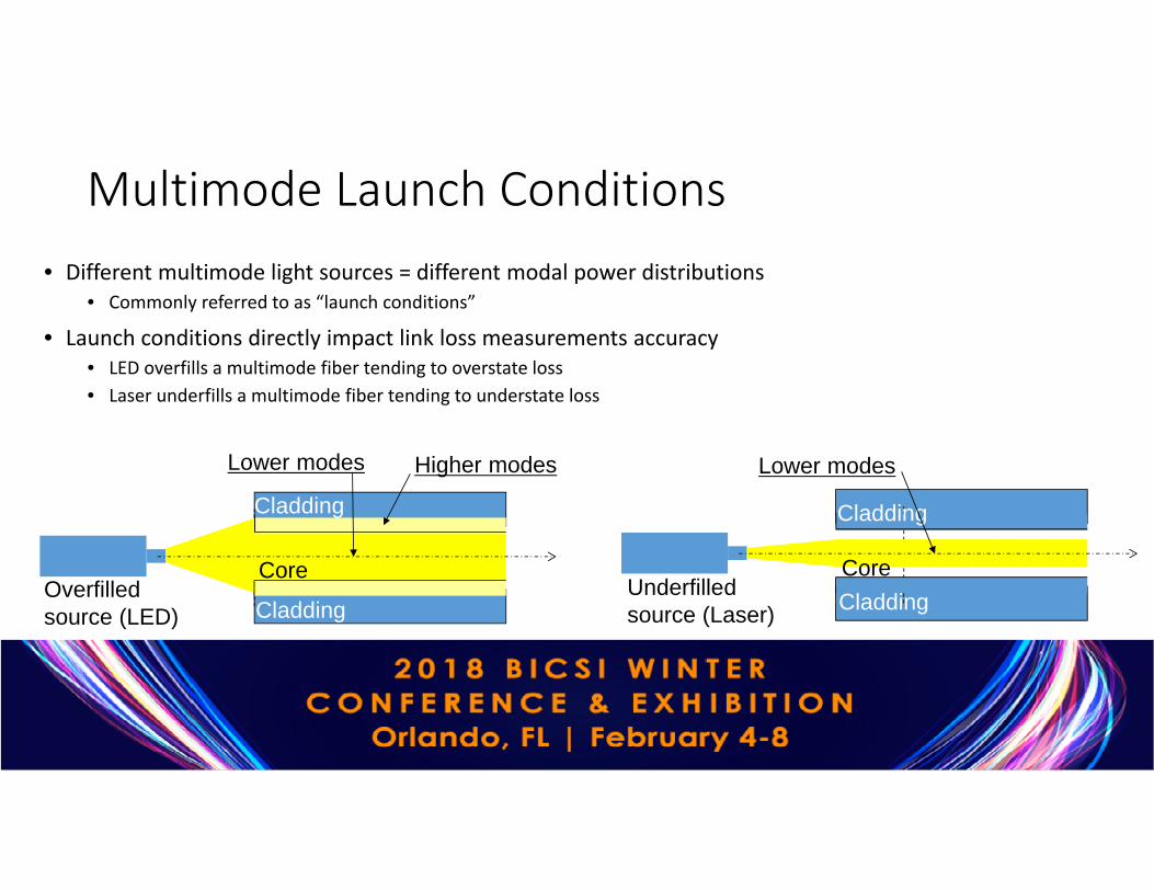
Multimode Launch Conditions• Different multimode light sources = different modal power distributions
• Commonly referred to as “launch conditions”
• Launch conditions directly impact link loss measurements accuracy• LED overfills a multimode fiber tending to overstate loss • Laser underfills a multimode fiber tending to understate loss
CoreOverfilled source (LED)
Cladding
Cladding
Higher modesLower modes
CoreUnderfilled source (Laser)
Cladding
Cladding
Lower modes

IEC 61280-4-1 sets standards for MM launch conditions• Ratio between the transmitted power at a given radius of the fiber core and the
total injected power
• Defined in IEC 61280-4-1 standard to characterize the launch conditions of MM test sources
• Is measured at the launch cord connector – NOT at the source output
• Replaces older “launch condition” requires such as Coupled Power Ratio (CPR)
• Can be achieved by using a universal or matched modal controller
0
0,1
0,2
0,3
0,4
0,5
0,6
0,7
0,8
0,9
1
0 5 10 15 20 25 30
radius (µm)
Enci
rcle
d flu
x
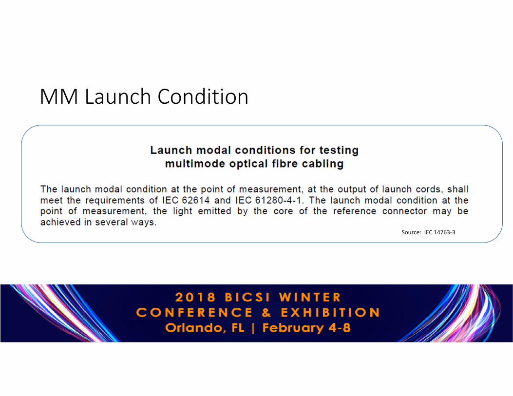
MM Launch Condition
Source: IEC 14763-3

Matched Controller
Universal and Matched Controllers• Universal Controller
• For legacy sources• Adds a “black box” to the output of the legacy source
• Matched Controller• Specific source matched with specific launch cord• Launch cord may have additional conditioning
Legacy Source Black Box
Universal Controller Specific Source Black Box
(optional)
Launch Cord

Test Reference Cords (TRCs)
• Use high performance (reference grade) connectors• Optimal optical and geometrical characteristics
• Numerical aperture (NA)• Core/ferrule concentricity
• When mated with other TRCs produce near zero loss• Minimizes uncertainty • Called for in various standards for loss measurements of installed fiber cabling
Source: IEC 61280-4-2

Losses associated with mating of TRCs
Source: IEC 61280-4-2
Source: IEC 61280-4-1

Correct Steps for Referencing
• Turn units on and let sources warm up for 5 min• Select and configure appropriate limit• Set reference method on device• Connect devices together according to reference method selected (+ Inspect)• Perform reference• Verify reference (+ Inspect)• Test (+ Inspect)
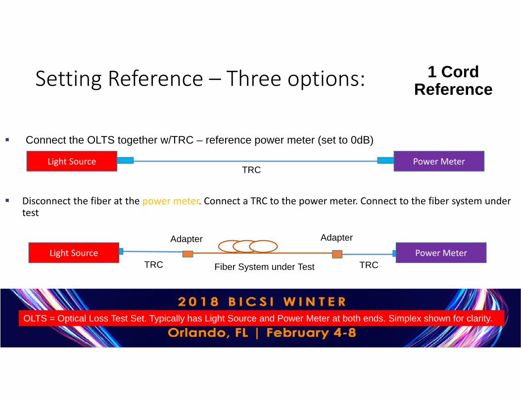
Connect the OLTS together w/TRC – reference power meter (set to 0dB)
1 Cord ReferenceSetting Reference – Three options:
Light Source Power MeterTRC
Light Source Power MeterTRC
Disconnect the fiber at the power meter. Connect a TRC to the power meter. Connect to the fiber system under test
TRCFiber System under Test
Adapter Adapter
OLTS = Optical Loss Test Set. Typically has Light Source and Power Meter at both ends. Simplex shown for clarity.

One-Cord Reference Method Source: IEC 61280-4-2
Light Source Power Meter
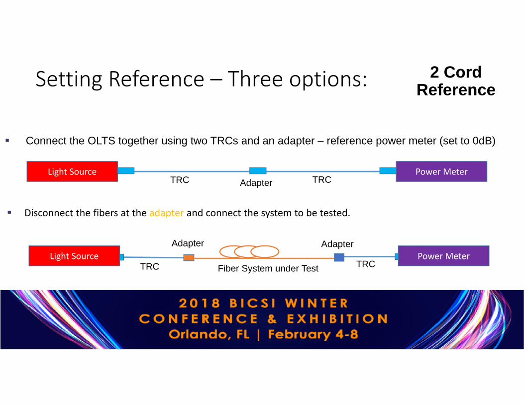
Connect the OLTS together using two TRCs and an adapter – reference power meter (set to 0dB)
Light Source Power Meter
Disconnect the fibers at the adapter and connect the system to be tested.
Adapter
Fiber System under Test
Adapter Adapter
TRC TRC
TRC TRC
2 Cord ReferenceSetting Reference – Three options:
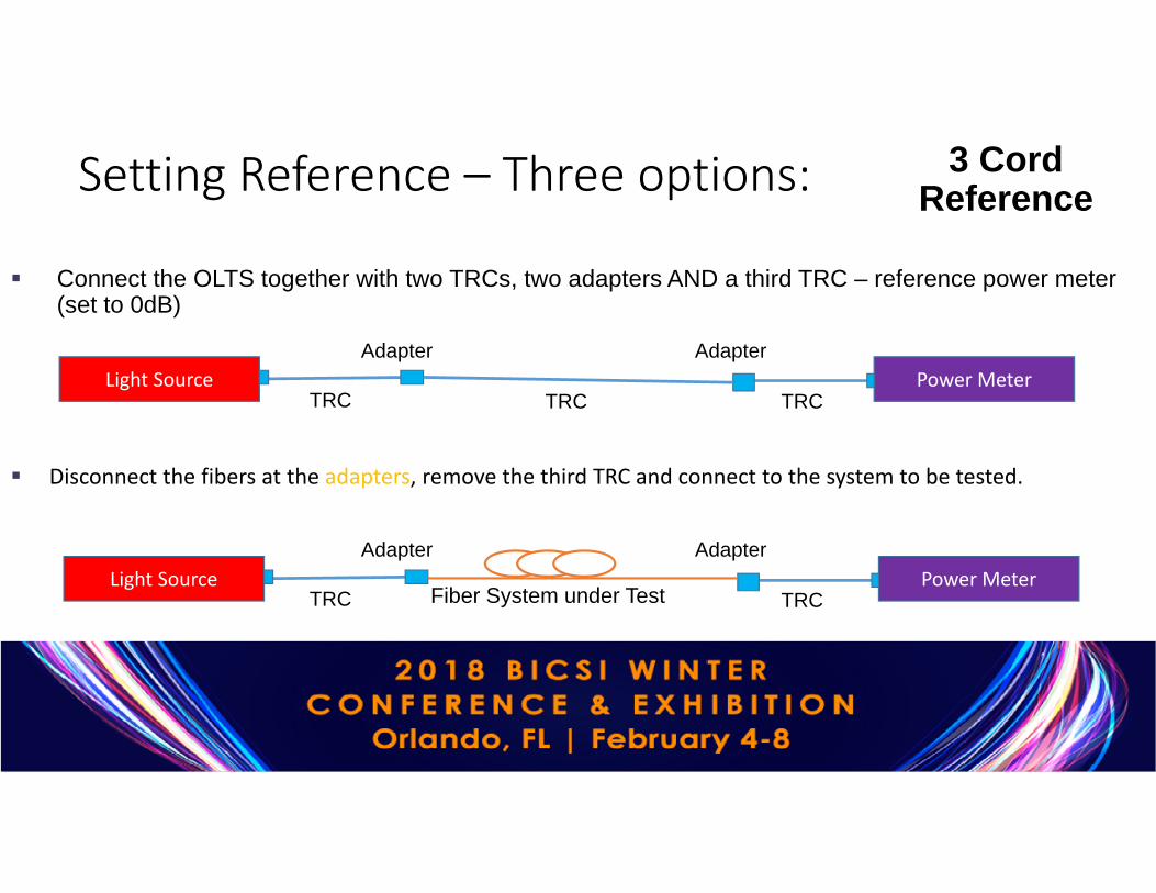
Connect the OLTS together with two TRCs, two adapters AND a third TRC – reference power meter (set to 0dB)
Light Source Power Meter
Disconnect the fibers at the adapters, remove the third TRC and connect to the system to be tested.
Light Source Power Meter
Fiber System under Test
Adapter
TRC TRCTRC
Adapter
Adapter
TRC TRC
Adapter
3 Cord ReferenceSetting Reference – Three options:

Reference Verification
• Connect test cords together and measure loss
• Ensure no “gainers”• Negative loss on most loss test sets
• Ensure loss does not exceed the values for TRC-TRC connections• Multimode ≤ 0.1 dB • Single mode ≤ 0.2 dB
• Save result for proof of good reference
AdapterLight Source Power Meter
TRC TRC
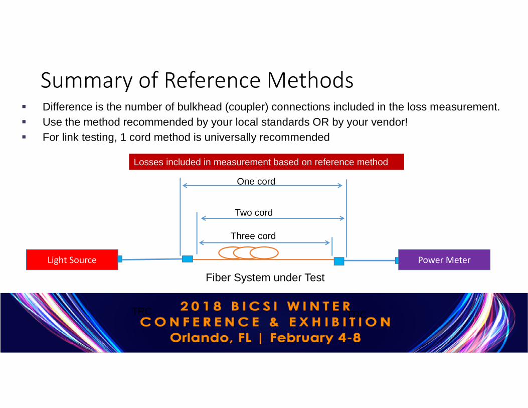
Summary of Reference Methods
Light Source Power Meter
TRC TRC
One cord
Two cord
Three cord
Difference is the number of bulkhead (coupler) connections included in the loss measurement. Use the method recommended by your local standards OR by your vendor! For link testing, 1 cord method is universally recommended
Losses included in measurement based on reference method
Fiber System under Test

• Acceptable loss limit is based on several factors:
• Number of connections • Number of splices• Loss per Km (at specific
wavelengths)
Loss Limits• Maximum allowable losses
• Loss per connection = 0.75 dB• Loss per splice= 0.3dB• Loss per Km (slope)
• 850nm = 3.0 dB• 1300nm = 1.5 dB• 1310 nm = 1.0 dB• 1550 nm = 1.0 dB
For Tier 1 Certification the user must tell the OLTS how many connections and splices are in the fiber system under test3.0 dB/Km
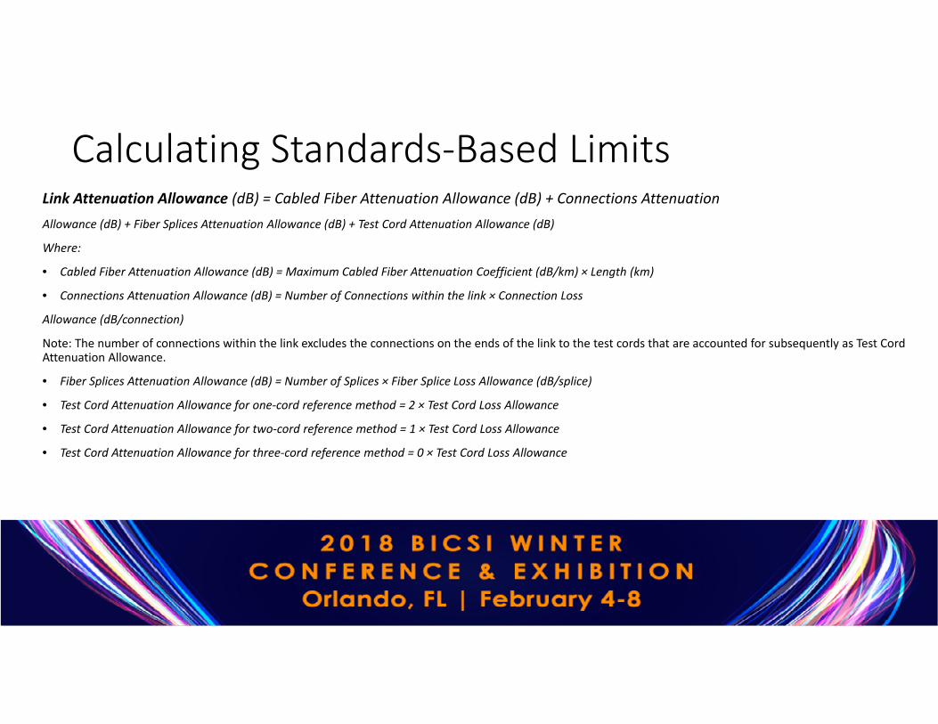
Calculating Standards-Based Limits Link Attenuation Allowance (dB) = Cabled Fiber Attenuation Allowance (dB) + Connections AttenuationAllowance (dB) + Fiber Splices Attenuation Allowance (dB) + Test Cord Attenuation Allowance (dB)
Where:
• Cabled Fiber Attenuation Allowance (dB) = Maximum Cabled Fiber Attenuation Coefficient (dB/km) × Length (km)
• Connections Attenuation Allowance (dB) = Number of Connections within the link × Connection Loss
Allowance (dB/connection)
Note: The number of connections within the link excludes the connections on the ends of the link to the test cords that are accounted for subsequently as Test Cord Attenuation Allowance.
• Fiber Splices Attenuation Allowance (dB) = Number of Splices × Fiber Splice Loss Allowance (dB/splice)
• Test Cord Attenuation Allowance for one-cord reference method = 2 × Test Cord Loss Allowance
• Test Cord Attenuation Allowance for two-cord reference method = 1 × Test Cord Loss Allowance
• Test Cord Attenuation Allowance for three-cord reference method = 0 × Test Cord Loss Allowance

Loss Limit Example
850 nm example:• Cabled fiber attenuation allowance = 3.0dB/km (0.3dB)
• Test cord attenuation allowance = 0.3dB x 2 (0.6dB)
• Connections• If no connections or splices in system under test, loss budget = 0.9dB• If two connections (0.75dB/connection) in system under test, loss budget = 2.4dB
Light Source Power MeterTRC TRCFiber System under Test
100m
Adapter Adapter
Limit is based on settingsLoss is measuredMargin in calculated
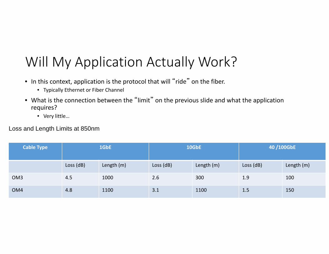
Will My Application Actually Work?• In this context, application is the protocol that will “ride” on the fiber.
• Typically Ethernet or Fiber Channel
• What is the connection between the “limit” on the previous slide and what the application requires?
• Very little…
Cable Type 1GbE 10GbE 40 /100GbE
Loss (dB) Length (m) Loss (dB) Length (m) Loss (dB) Length (m)
OM3 4.5 1000 2.6 300 1.9 100
OM4 4.8 1100 3.1 1100 1.5 150
Loss and Length Limits at 850nm

Compliant Networks• Most Enterprise Optical Loss Test Sets will report “Compliant Networks”
based on loss measurement
• Cautions! • Can “PASS” standards-based generic limit, but have too much loss
for specific application• Most testing performed is on links – but applications run on
channels
• If the Application to be carried on the fiber is known• Then use Application (Network) limit on your test device
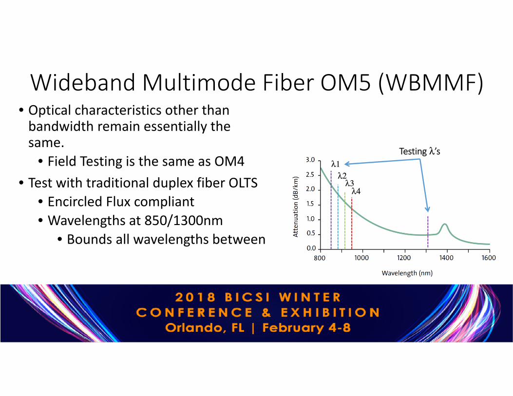
Wideband Multimode Fiber OM5 (WBMMF)• Optical characteristics other than
bandwidth remain essentially the same.
• Field Testing is the same as OM4• Test with traditional duplex fiber OLTS
• Encircled Flux compliant• Wavelengths at 850/1300nm
• Bounds all wavelengths between
λ1λ2
Testing λ’s
λ3λ4
Tier 1 Testing for MPO
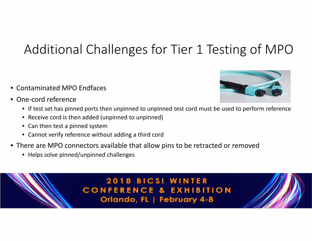
Additional Challenges for Tier 1 Testing of MPO
• Contaminated MPO Endfaces• One-cord reference
• If test set has pinned ports then unpinned to unpinned test cord must be used to perform reference• Receive cord is then added (unpinned to unpinned)• Can then test a pinned system • Cannot verify reference without adding a third cord
• There are MPO connectors available that allow pins to be retracted or removed• Helps solve pinned/unpinned challenges
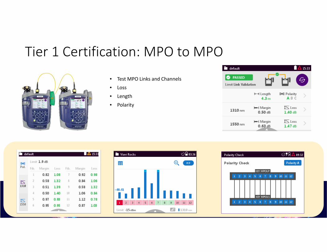
Tier 1 Certification: MPO to MPO
• Test MPO Links and Channels• Loss
• Length
• Polarity

Tier 1 Certification: MPO to MPOMPO Bulkhead MPO Bulkhead
MPO Backbone MPO Test CordMPO Test Cord
MPOOptical Light Source
MPOOptical Power Meter

MPO Connectors are more likely to be contaminated
1.25mm ferrule = 1.2mm2 area 9.5mm X 5.0mm opening = 47.5mm2 area
If 1 fiber is 95% likely to be clean, 12 fibers are (0.95)12 = 55% likely to be clean
Single-Fiber Connector MPO ConnectorWhite ceramic ferrule One fiber per connector Common types include LC,
SC, FC, and ST Smaller Surface Area
Polymer ferruleMultiple fibers in linear array 6x or 12x density connectivity Larger Surface Area

Follow this simple “INSPECT BEFORE YOU CONNECT” process to ensure fiber end faces are clean prior to mating MPO connectors.

Anatomy of a 12-fiber Multi-Mode MPO Connector
Note: MPO connectors with higher fiber counts (e.g. 24) will have multiple rows of fiber on the ferrule

Consider Cloud Solutions for Tier 1 Certification• Manage projects with confidence at every stage• Align your team and project requirements in one place• Increase team workflow with cloud connectivity• Track project status and analyze results from anywhere• Enhance your test tools for greater productivity• Generate Tier 1 certification reports & more
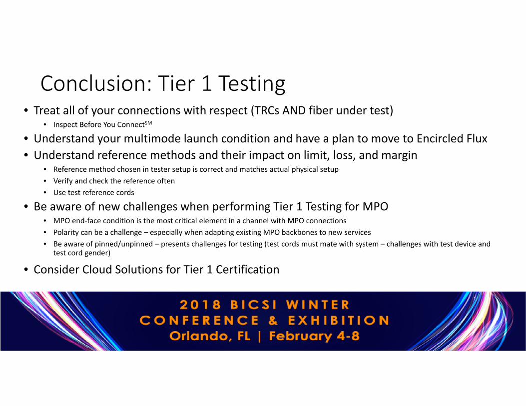
Conclusion: Tier 1 Testing• Treat all of your connections with respect (TRCs AND fiber under test)
• Inspect Before You ConnectSM
• Understand your multimode launch condition and have a plan to move to Encircled Flux• Understand reference methods and their impact on limit, loss, and margin
• Reference method chosen in tester setup is correct and matches actual physical setup• Verify and check the reference often• Use test reference cords
• Be aware of new challenges when performing Tier 1 Testing for MPO• MPO end-face condition is the most critical element in a channel with MPO connections• Polarity can be a challenge – especially when adapting existing MPO backbones to new services• Be aware of pinned/unpinned – presents challenges for testing (test cords must mate with system – challenges with test device and
test cord gender)
• Consider Cloud Solutions for Tier 1 Certification

Tier-2 OTDR testing & troubleshooting
Jamie Humphreys Senior Technical Sales Specialist
EXFO
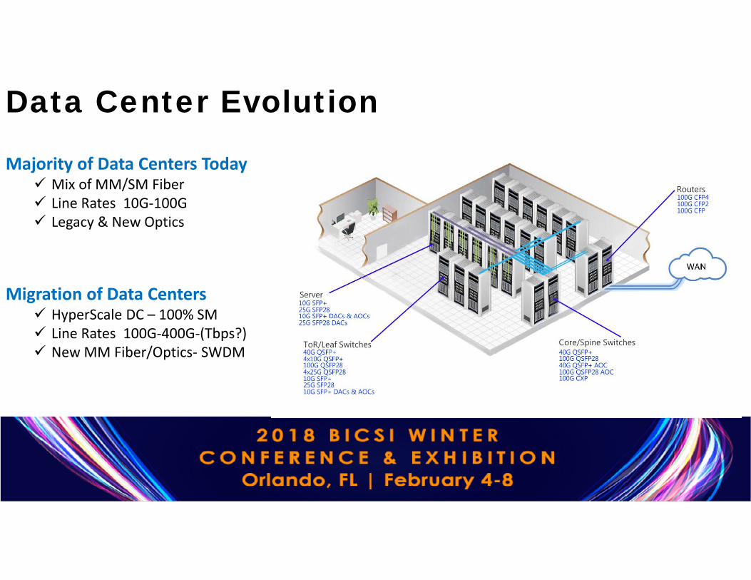
Majority of Data Centers Today Mix of MM/SM Fiber Line Rates 10G-100G Legacy & New Optics
Migration of Data Centers HyperScale DC – 100% SM Line Rates 100G-400G-(Tbps?) New MM Fiber/Optics- SWDM
Data Center Evolution
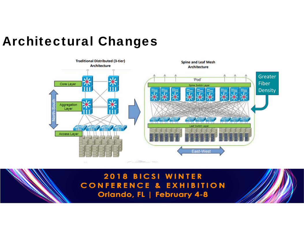
Architectural Changes
GreaterFiberDensity

AssuringQuality
Network PerformanceMacrobends
Located
Loss/Locationof each Splice and
Connector
Link ORL
Connector Reflection
Tier 2- OTDR Functions Adverselyaffects100G +TransmissionPerformance
Link Loss/ DistanceEnd of the Fiber
Indication of Connector CleanlinessAnd quality of endface termination

© 2017 EXFO Inc. All rights reserved.
Dirty connectors Fiber cuts /High lossMacrobends
Clean connectors Clean fiber management
OTDR Helps Assure Network QualityLOCATES:

In order to properly measure the loss and refection of the first and the last connectors, launch and receive cables are required
OTDR Basics- Launch/Receive Cable
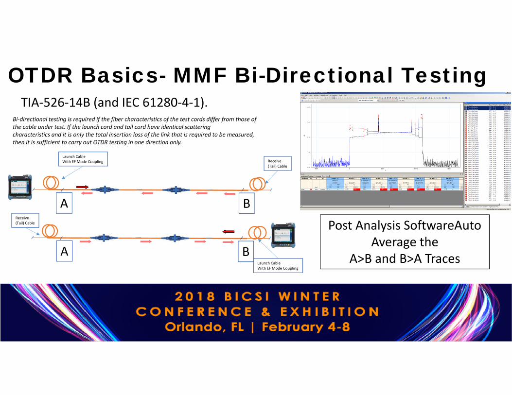
TIA-526-14B (and IEC 61280-4-1).
OTDR Basics- MMF Bi-Directional Testing
Launch CableWith EF Mode Coupling Receive
(Tail) Cable
Receive (Tail) Cable
A
A
B
B
Bi-directional testing is required if the fiber characteristics of the test cords differ from those of the cable under test. If the launch cord and tail cord have identical scatteringcharacteristics and it is only the total insertion loss of the link that is required to be measured, then it is sufficient to carry out OTDR testing in one direction only.
Launch CableWith EF Mode Coupling
Post Analysis SoftwareAuto Average the
A>B and B>A Traces
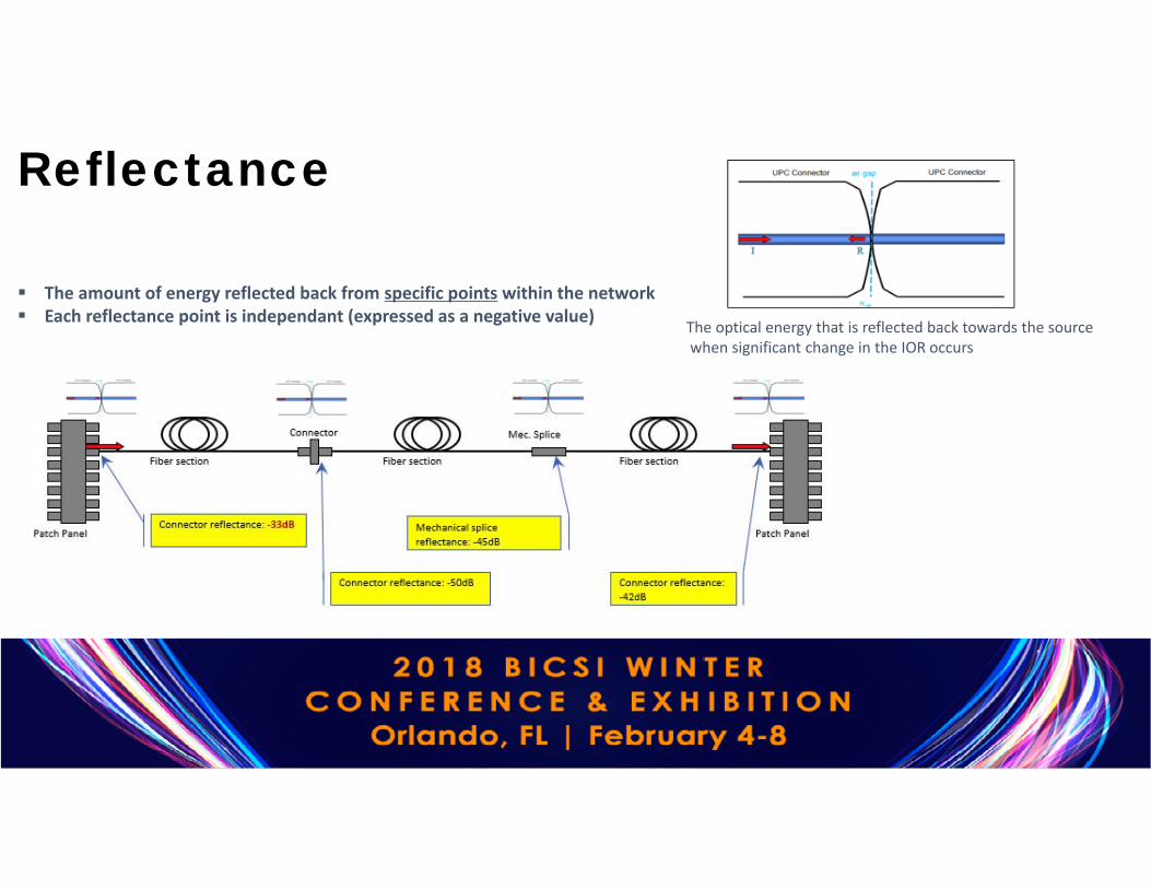
The amount of energy reflected back from specific points within the network Each reflectance point is independant (expressed as a negative value) The optical energy that is reflected back towards the source
when significant change in the IOR occurs
Reflectance

Rates MMF Budget loss in dB @ 850 nm
(Reach)
SMF Budget loss in dB @
1310/1550 nm (Reach)
Connector Reflectance
(dB)Standard
Connector Reflectance
(dB)Customers
10GBASE(IEEE 802.3ae 2002)
S- Serial (OM3/4)2.6 (300m)
L- Serial (OS1-OS2)6.0 (10km)
-20 (MMF)-26 (SMF) No requirements
40GBASE-SR4100GBASE-SR1040GBASE-LR4100GBASE-LR4(IEEE 802.3bm – 2015)
SR4 / SR101.9 (70m) (OM3)
1.5 (100m) (OM4)
LR4 (OS1-OS2)6.7 (10km)
-20 (MMF)-26 (SMF)
-35 dB TIA-568.3-D
-40 to -45 dB (SMF / UPC polish)
4x25G lanes
New MSAs:100G-PSM4 (4X25 MPO)100G-CWDM4 (4x25 LC)100G-SWDM4 (LC)
OM5/SWDM41,5 (100m)
OS1-OS23.3 dB (500m)5.0 dB (2km)
-20 (MMF)-26 (SMF)
-40 to -45 dB
Loss/Reflectance Tolerances

10-12 dB average change (clean vs. oil)
Strict correlation (clean vs. oil)0.7
0.6
0.5
0.4
0.3
0.2
0.1
0
70
60
50
40
30
20
10
0
Reflectance : Growing ConcernReflectance Thresholds:
Standards (TIA-568.3-D (2013, b.3), IEC-11801 (2010): SMF 35dB (MMF 20dB)
IEEE 802.3bs (200 – 400G): SMF -45 to -47dB for each discrete reflectance (4 connectors+) – standard not yet ratified.
TypicalOperatorRequirement
Finger oil
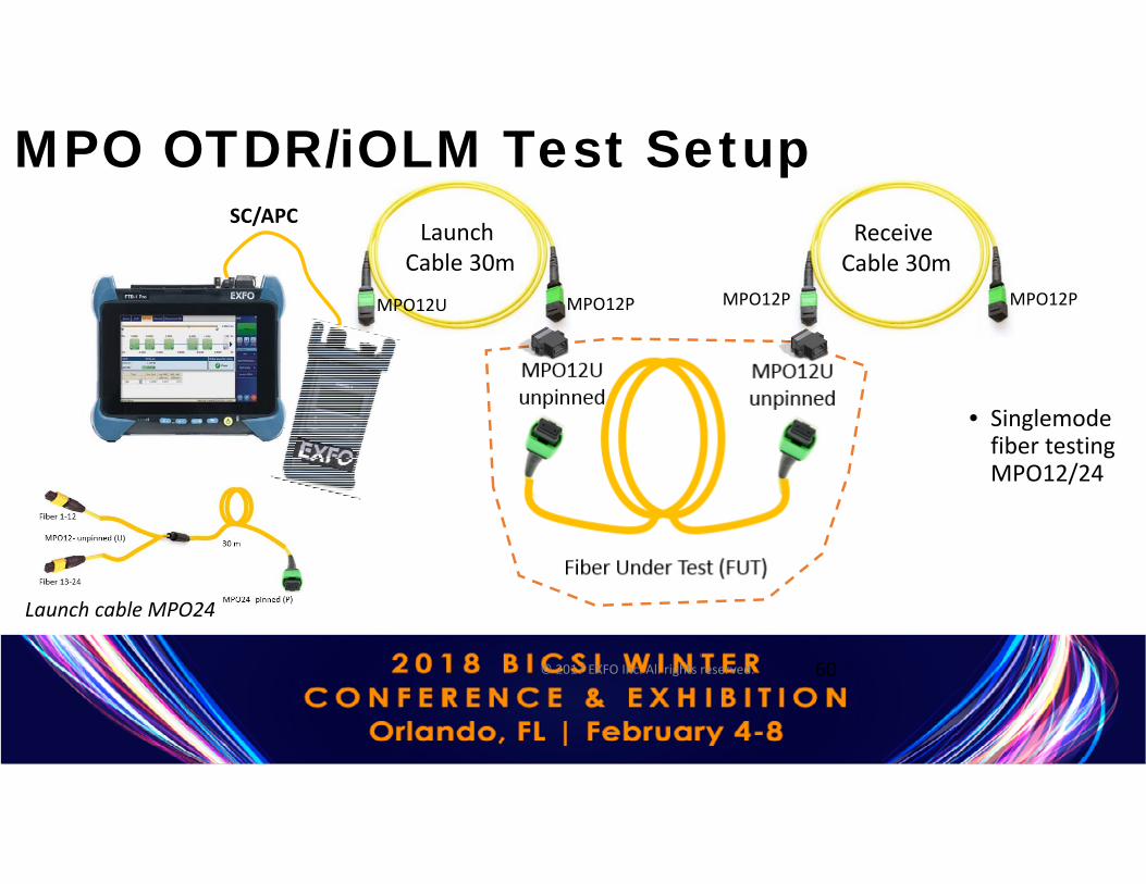
MPO OTDR/iOLM Test Setup
© 2017 EXFO Inc. All rights reserved. 60
• Singlemode fiber testing MPO12/24
Launch Cable 30m
Receive Cable 30m
MPO12PMPO12PMPO12U MPO12P
Launch cable MPO24
SC/APC

© 2017 EXFO Inc. All rights reserved. 6
1Receive
SC/APC
SC/APC
MPO12/APC
MPO12/APC
MPO12/APC
Launch
3
4
2
1
20 meters 20 meters
30 meters
NetworkMPOOTDRTest
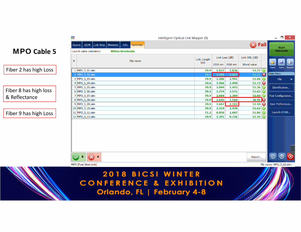
MPO Cable 5
Fiber 2 has high Loss
Fiber 8 has high loss & Reflectance
Fiber 9 has high Loss
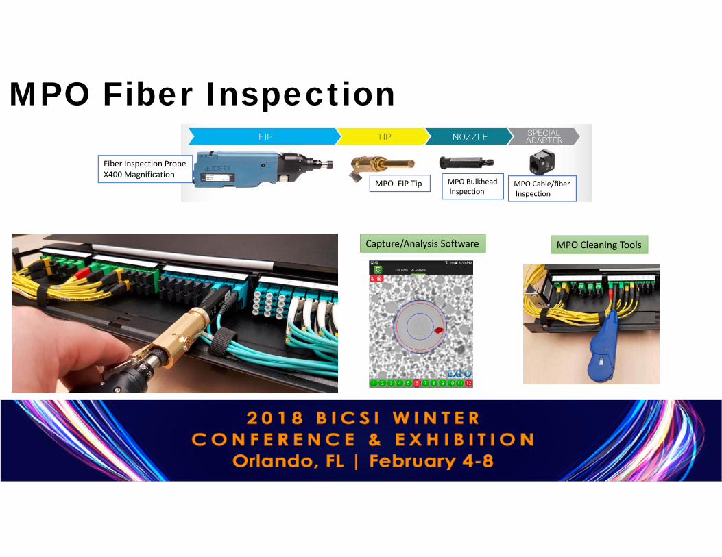
MPO Fiber Inspection
Fiber Inspection ProbeX400 Magnification
MPO FIP Tip MPO BulkheadInspection
MPO Cable/fiberInspection
Capture/Analysis Software MPO Cleaning Tools

MPO Inspection CriteriaCapture/Analysis Software
© 2017 EXFO Inc. All rights reserved. 65
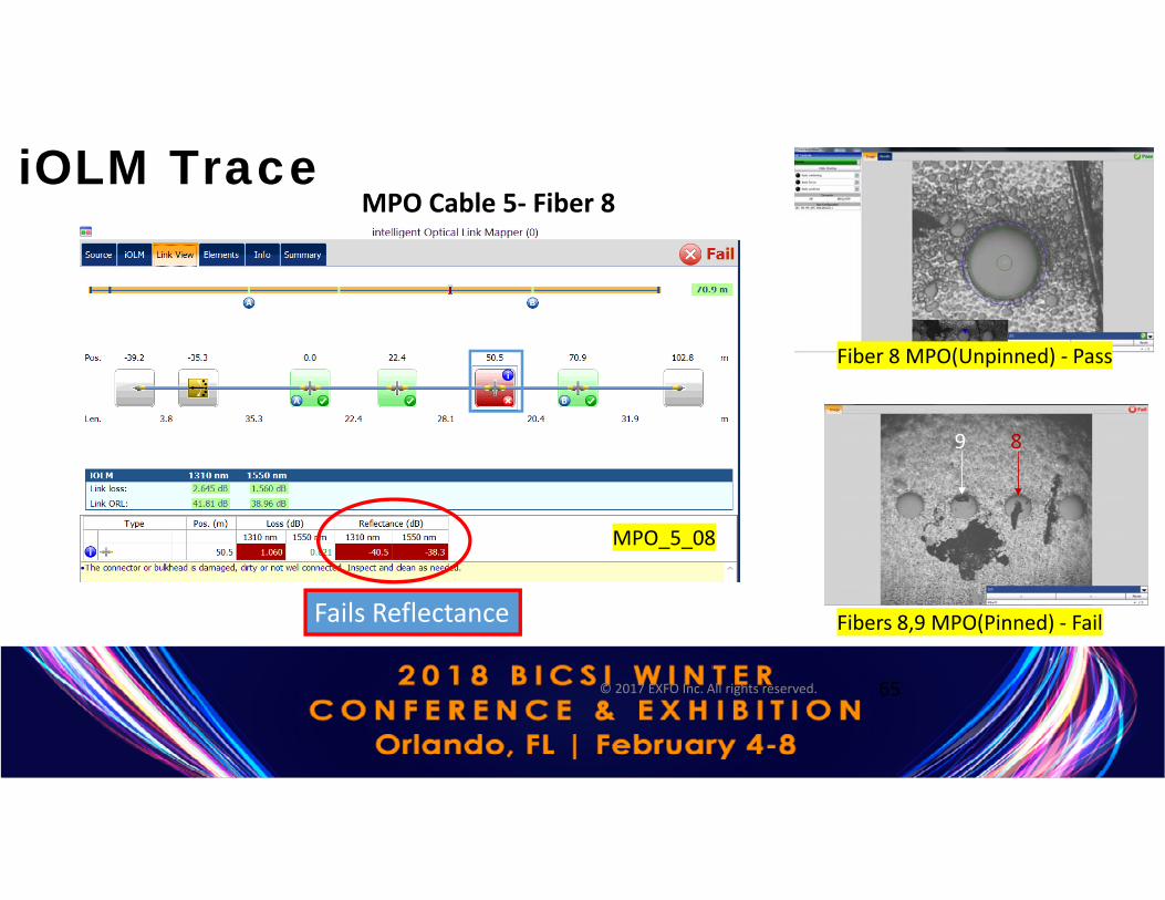
MPO_5_08
Fails Reflectance
Fiber 8 MPO(Unpinned) - Pass
9 8
Fibers 8,9 MPO(Pinned) - Fail
MPO Cable 5- Fiber 8iOLM Trace

Fiber 9 MPO(U),after wet /dry
9 8
Fiber 8-9 MPO(P),after wet /dry
MPO-SMF OTDR/Switch Test Case

Test Equipment Manager SW Revision Control Inventory Control
Test Equipment Manager SW Revision Control Inventory Control
Remote Control Run Tests Remotely Shared application specific test licenses
Test Data Manager Test Results Uploaded Test Configurations &
Test Plans Downloaded
Test Data Manager Test Results Uploaded Test Configurations &
Test Plans Downloaded
Cloud Based Test Management
