ten fundamentals - agilent technologies
TRANSCRIPT
TenFundamentalsYou Need to Know About Your DC Power Supply
2
Understanding how measure-
ment tools operate can provide
insight into how to improve
testing methods. With modern
performance and safety features
in power supplies, the flexibility
exists to create test setups that
are simpler and more effective.
Use these 10 fundamentals
about your power supply to take
advantage of these features.
IntroductionIntroductionIntroductionContents
1 Program Your Power Supply Correctly to Operate in Constant Voltage or Constant Current Mode / 3
2 Use Remote Sense to Regulate Voltage at Your Load / 4
3 Use Your Power Supply to Measure DUT Current / 5
4 Connect Power Supply Outputs in Series or Parallel for More Power / 6
5 Minimize Noise From Your Power Supply to Your DUT / 7
6 Safeguard Your DUT Using Built-in Power Supply Protection Features / 8
7 Use Output Relays to Physically Disconnect Your DUT / 9
8 Capture Dynamic Waveforms Using a Power Supply’s Built-in Digitizer / 10
9 Create Time-Varying Voltages Using Power Supply List Mode / 11
10 Tips for Rack-Mounting Your Power Supply / 12
Glossary / 13
3
The output of a power supply can operate
in either constant voltage (CV) mode or
constant current (CC) mode depending on
the voltage setting, current limit setting,
and load resistance. In most circum-
stances, a power supply output operates
in either CV or CC mode. However, there
are some unusual circumstances that will
cause the power supply to enter a third
mode called unregulated (UNR) mode.
Understanding these three modes will
make it easier to correctly program your
power supply.
Constant Voltage
A power supply will operate in constant
voltage (CV) mode provided the load
does not require more current than the
current limit setting. Based on Ohm’s law,
V = I x R, maintaining a constant voltage
while changing the load resistance
requires the current to increase or
decrease. As long as the current draw
Iout = Vs/RL is less than the current limit
setting, the power supply regulates the
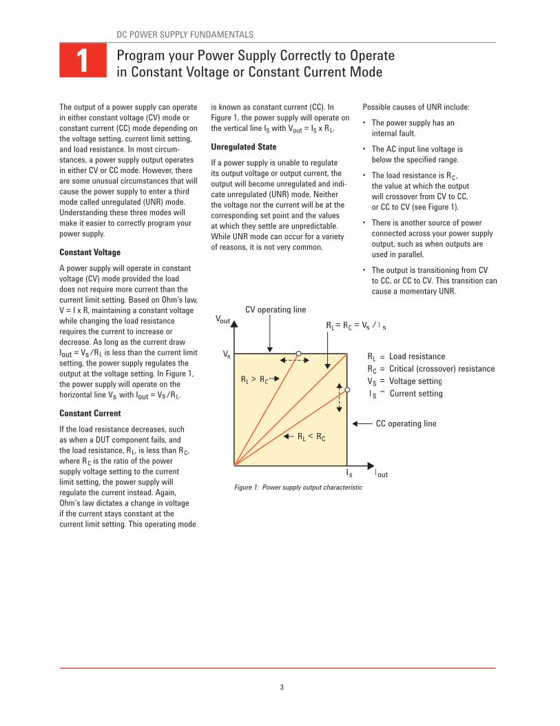
output at the voltage setting. In Figure 1,
the power supply will operate on the
horizontal line Vs with Iout = Vs/RL.
Constant Current
If the load resistance decreases, such
as when a DUT component fails, and
the load resistance, RL, is less than RC,
where RC is the ratio of the power
supply voltage setting to the current
limit setting, the power supply will
regulate the current instead. Again,
Ohm’s law dictates a change in voltage
if the current stays constant at the
current limit setting. This operating mode
is known as constant current (CC). In
Figure 1, the power supply will operate on
the vertical line IS with Vout = IS x RL.
Unregulated State
If a power supply is unable to regulate
its output voltage or output current, the
output will become unregulated and indi-
cate unregulated (UNR) mode. Neither
the voltage nor the current will be at the
corresponding set point and the values
at which they settle are unpredictable.
While UNR mode can occur for a variety
of reasons, it is not very common.
Possible causes of UNR include:
• The power supply has an
internal fault.
• The AC input line voltage is
below the specified range.
• The load resistance is RC,
the value at which the output
will crossover from CV to CC,
or CC to CV (see Figure 1).
• There is another source of power
connected across your power supply
output, such as when outputs are
used in parallel.
• The output is transitioning from CV
to CC, or CC to CV. This transition can
cause a momentary UNR.
CV operating line
CC operating line
VoutVV
VsVV
VsVV I s
Is Iout
RL RC>
RL RC<
RL
RL
RC
VS
I S
Load resistance
Critical (crossover) resistance
Voltage setting
Current setting
RC=
=
=
=
=
= /
Figure 1: Power supply output characteristic
Program your Power Supply Correctly to Operate in Constant Voltage or Constant Current Mode 1DC POWER SUPPLY FUNDAMENTALS
4
Ideally, lead connections from your power
supply to your load have no resistance.
In reality, lead resistance increases
with lead length and wire gauge. The
resulting effect when a supply delivers
current through the wire may decrease
the voltage at the load. To compensate,
use remote sensing to correct for these
voltage drops.
Typically, a power supply is shipped
from the factory with the sense leads
connected locally at the output terminals.
However, for setups with long load leads
or for complex setups with relays and
connectors, the voltage at the output
terminals will not accurately represent
the voltage at the load. (Figure 2)
Depending on the gauge and length of
wire, the resistivity of your load connec-
tions could cause a much lower voltage
at your load than you want. High current
situations, for example, will invariably
lead to significant voltage drops even
with short load leads. Consider the
resistances of different gauges of
copper wire in the following table:
As a general rule, for every 3-gauge
increase in your copper wire, the resis-
tance doubles. Since you must select the
proper gauge wire to satisfy the current
requirements of the load, remote sense
at the load will improve voltage regula-
tion without shortening lead length or
decreasing wire gauge.
When you connect the remote sense ter-
minals to the load, the internal feedback
amplifier sees the voltage directly at the
load, rather than at the output terminals.
Since the control loop senses the voltage
directly at the load, the supply will keep
the load voltage constant, regardless
of voltage drops caused by load lead
gauge, load lead length, output relays, or
connectors.
Remember the following when you use
remote sense:
• Use two-wire twisted shielded cable
for your sense leads.
• Connect the sense lead cable’s shield
to ground on only one end of the cable.
• Do not twist or bundle sense leads
together with load leads.
• Prevent an open circuit at the sense
terminals, as they are part
of the output’s feedback path.
Agilent uses internal sense protect
resistors. These resistors prevent
the output voltage from rising more
than a few percent if the sense
leads inadvertently open.
• Most supplies can compensate only
for a maximum load lead drop of
a few volts.
To implement remote sense (Figure 3):
1. Disconnect the sense terminal
connections from the main outputs.
2. Connect each sense terminal to
the proper polarity load contact.
3. If necessary, set the power supply
to remote sense mode or 4-wire mode.
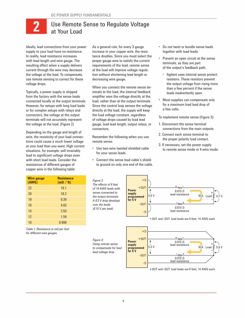
Figure 2:
The effects of 6 feet
of 14 AWG leads with
sense connected to
the output terminals.
A 0.3 V drop develops
over the leads
(0.15 V per lead).
Figure 3:
Using remote sense
to compensate for load
lead voltage drop
Table 1: Resistance in mΩ per foot
for different wire gauges
Wire gauge(AWG)
Resistance(mΩ / ft)
22 16.1
20 10.2
18 6.39
16 4.02
14 2.53
12 1.59
10 0.999
2DC POWER SUPPLY FUNDAMENTALS
Use Remote Sense to Regulate Voltage at Your Load
+
+
+
S
--
---
---+-----
S
+OUT
+
+
OUT and --OUT load leads are 6 feet, 14 AWG each
OUT and --OUT load leads are 6 feet, 14 AWG each
OUT
5.0 V
0.015 Ωlead resistance
0.015 Ωlead resistance
Powersupplyprogrammedfor 5 V
Load
+
+
S
--
---
+-----
S
+OUT
OUT
5.3 V
0.015 Ωlead resistance
0.015 Ωlead resistance
Powersupplyprogrammedfor 5 V
Load
4.7 V
+
---5.0 V
10 A
10 A
5
You can obtain an accurate DUT current
measurement with an ammeter, a
current shunt, or the built-in readback
on your power supply. Ultimately, you
should select one method over another
after considering the advantages and
disadvantages of each. More often than
not, the current readback on your power
supply can provide you with the accuracy
you need for a measurement.
Ammeter
A common way to measure DUT current
is to use a bench DMM set in ammeter
mode. While an ammeter has the benefit
of a specified accuracy, you must break
the circuit to insert the ammeter. A DMM
also has a limit on the maximum current
you can measure, typically several amps.
External current shunt/DMM
You can also make current measurements
with shunts. With a current shunt,
you can conveniently select the most
appropriate shunt resistor to match your
current range. Your accuracy is based on
the DMM’s voltage measurement accu-
racy and the precision of the shunt. While
this method can produce highly accurate
results, certain errors can adversely
affect your measurements. You must pay
attention to these commonly overlooked
complications:
• Thermal EMF – dissimilar metals
cause thermocouple voltages to
develop
• Shunt miscalibration – accurate read-
ings require calibration of the shunt
resistance
• Self-heating effects – higher tempera-
ture from current flow can cause shunt
resistance to change
In addition to these concerns, installing
a current shunt requires you to break
your circuit in order to connect the shunt
in series. A current shunt installed in a
rack-mount system may even require
complex connections involving relays
and switches.
Built-in current readback
You can avoid the difficulties involved
with connecting current shunts by using
a power supply’s built-in readback.
Current readback on a power supply uses
an internal shunt, selected to comple-
ment the output rating of the supply. You
do not need to disconnect the DUT or
connect a DMM.
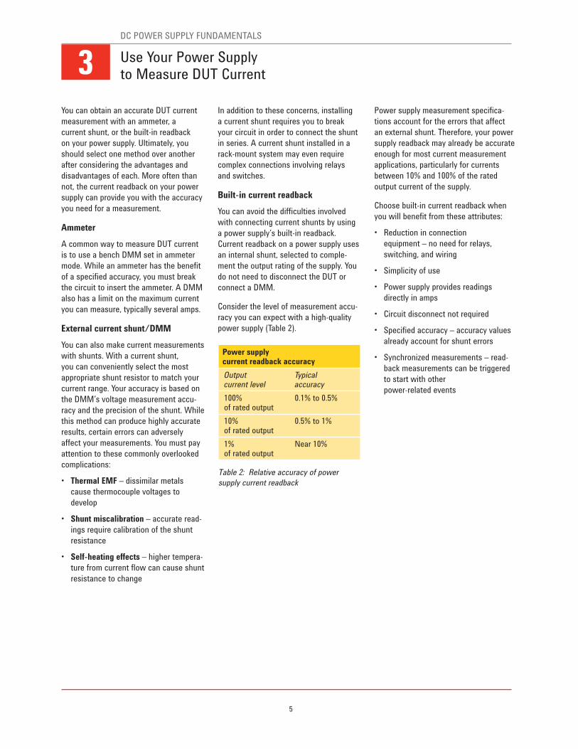
Consider the level of measurement accu-
racy you can expect with a high-quality
power supply (Table 2).
Power supply measurement specifica-
tions account for the errors that affect
an external shunt. Therefore, your power
supply readback may already be accurate
enough for most current measurement
applications, particularly for currents
between 10% and 100% of the rated
output current of the supply.
Choose built-in current readback when
you will benefit from these attributes:
• Reduction in connection
equipment – no need for relays,
switching, and wiring
• Simplicity of use
• Power supply provides readings
directly in amps
• Circuit disconnect not required
• Specified accuracy – accuracy values
already account for shunt errors
• Synchronized measurements – read-
back measurements can be triggered
to start with other
power-related events
Table 2: Relative accuracy of power
supply current readback
Power supply current readback accuracy
Output current level
Typical accuracy
100% of rated output
0.1% to 0.5%
10% of rated output
0.5% to 1%
1% of rated output
Near 10%
3DC POWER SUPPLY FUNDAMENTALS
Use Your Power Supply to Measure DUT Current
6
You can connect two or more power sup-
ply outputs in series to get more voltage,
or connect outputs in parallel
to get more current.
When you connect outputs in series for
higher voltage, observe the following
precautions:
• Never exceed the floating voltage rat-
ing (output terminal isolation)
of any of the outputs
• Never subject any of the power supply
outputs to a reverse voltage
• Only connect outputs that have
identical voltage and current ratings
in series
Set each power supply output indepen-
dently so that the voltages sum to the
total desired value. To do this, first set
each output to the maximum desired
current limit the load can safely handle.
Next, set the voltage of each output to
sum to the total desired voltage. For
example, if you are using two outputs, set
each to one half the total desired voltage.
If you are using three outputs, set each to
one third the total desired voltage.
When you connect outputs in parallel
for higher current, observe the following
precautions:
• One output must operate in constant
voltage (CV) mode and the other(s)
in constant current (CC) mode
• The output load must draw enough
current to keep the CC output(s)
in CC mode
• Only connect outputs that have
identical voltage and current ratings
in parallel
Set the current limit of all outputs equally
such that they sum to the total desired
current limit value. Set the voltage of the
CV output to a value slightly lower than
the voltage value of the CC outputs. The
CC outputs supply the output current to
which they have been set and drop their
output voltage until they match the volt-
age of the CV unit, which supplies only
enough current to fulfill the total load
demand.
To sense the voltage directly at the load,
use remote sense with your series or
parallel setup. For some power supplies,
you must deliberately set each output
for “remote sense,” sometimes called
“4-wire mode.”
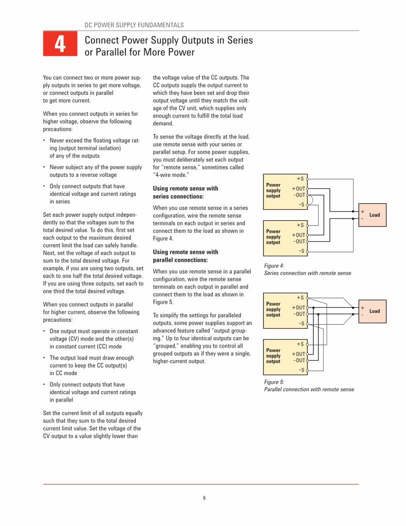
Using remote sense with
series connections:
When you use remote sense in a series
configuration, wire the remote sense
terminals on each output in series and
connect them to the load as shown in
Figure 4.
Using remote sense with
parallel connections:
When you use remote sense in a parallel
configuration, wire the remote sense
terminals on each output in parallel and
connect them to the load as shown in
Figure 5.
To simplify the settings for paralleled
outputs, some power supplies support an
advanced feature called “output group-
ing.” Up to four identical outputs can be
“grouped,” enabling you to control all
grouped outputs as if they were a single,
higher-current output.
Connect Power Supply Outputs in Series or Parallel for More Power
+S
--S
+OUT--OUT
Powersupplyoutput
+S
--S
+OUT--OUT
Powersupplyoutput
+--
Load
+S
--S
+OUT--OUT
Powersupplyoutput
+S
--S
+OUT--OUT
Powersupplyoutput
+--
Load
Figure 4:
Series connection with remote sense
Figure 5:
Parallel connection with remote sense
4DC POWER SUPPLY FUNDAMENTALS
7
If your DUT is sensitive to noise on its
DC power input, you will want to do
everything you can to minimize noise on
the input. Here are three simple steps
you can take.
Choose a power supply that has
low noise
To minimize noise, start at your source.
Since filtering noise from your power
supply can be difficult, you want to select
a power supply that has very low noise to
begin with. Choosing a linearly regulated
power supply can accomplish this; how-
ever, linear power supplies can be large
and can generate large amounts of heat.
Instead, consider choosing a switching-
regulated power supply. Modern
switch-mode power supply technology
has improved to the point where the
noise on the output can be comparable to
that of a linear supply. A comparison of
noise on a typical linear supply versus a
performance switching supply is shown
in Table 3.
Table 3: A comparison of power
supply noise for linearly regulated versus
switching-regulated supplies
Selecting a supply with low RMS and
peak-to-peak output voltage noise
specifications is an excellent start, but
you can also minimize the noise with
proper attention to the lead connections
to your DUT.
Shield supply-to-DUT connections
The connections between your supply
and DUT can be susceptible to noise
pick-up. Different types of interference
include inductive coupling, capacitive
coupling, and radio frequency interfer-
ence. There are a number of ways to
reduce noise, but the most effective
is to ensure your load and sense connec-
tions use shielded two-wire cables.
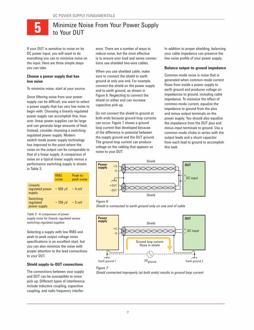
When you use shielded cable, make
sure to connect the shield to earth
ground at only one end. For example,
connect the shield on the power supply
end to earth ground, as shown in
Figure 6. Neglecting to connect the
shield on either end can increase
capacitive pick-up.
Do not connect the shield to ground at
both ends because ground loop currents
can occur. Figure 7 shows a ground
loop current that developed because
of the difference in potential between
the supply ground and the DUT ground.
The ground loop current can produce
voltage on the cabling that appears as
noise to your DUT.
In addition to proper shielding, balancing
your cable impedance can preserve the
low noise profile of your power supply.
Balance output-to-ground impedance
Common-mode noise is noise that is
generated when common-mode current
flows from inside a power supply to
earth ground and produces voltage on
impedances to ground, including cable
impedance. To minimize the effect of
common-mode current, equalize the
impedance to ground from the plus
and minus output terminals on the
power supply. You should also equalize
the impedance from the DUT plus and
minus input terminals to ground. Use a
common-mode choke in series with the
output leads and a shunt capacitor
from each lead to ground to accomplish
this task.
+S
--S
+OUT
--OUT
Shield
Shield
DC input
Powersupply
+
--
DUT
+S
--S
Shield
Earth ground 2Earth ground 1
Ground loop currentflows in shield
∆Vground
DC input
Powersupply
+--
DUT
Minimize Noise From Your Power Supply to Your DUT
RMS noise
Peak-to-peak noise
Linearly regulated power supply
~ 500 μV ~ 4 mV
Switching-regulated power supply
~ 750 μV ~ 5 mV Figure 6:
Shield is connected to earth ground only on one end of cable
Figure 7:
Shield connected improperly (at both ends) results in ground loop current
5DC POWER SUPPLY FUNDAMENTALS
8
Most DC power supplies have features
that protect sensitive DUTs and circuitry
from exposure to potentially damaging
voltage or current. When the DUT trips
a protection circuit in the power supply,
the protection circuit turns off the output
and displays a notification. Two common
protection features are over-voltage and
over-current protection.
When you design your test, it is impor-
tant to understand these protection
features to protect your DUT.
Over-voltage protection (OVP)
OVP is a value set in volts designed to
protect your DUT from excessive voltage.
When the power supply output voltage
exceeds your OVP setting, the protection
will trip and turn off the output.
OVP is always enabled. When power sup-
plies are shipped from the factory, OVP
is typically set well above the maximum
rated output of the power supply. Set
your OVP trip voltage low enough to pro-
tect your DUT from excessive voltage, but
high enough to prevent nuisance tripping
from normal fluctuations in the output
voltage. Fluctuations can occur during
output transient conditions, such as load
current changes.
CAUTION: On most power supplies, OVP
responds to the voltage at the output
terminals, not the sense terminals. When
using remote sense, program your OVP
trip voltage high enough to account for
load lead voltage drops.
OVP circuits can respond to an over-volt-
age condition in microseconds, however,
the output voltage itself will take longer
to go down. The time for the output to go
down depends on the down-programming
capabilities of the power supply and the
load that is connected to the output. Some
power supplies have a silicon-controlled
rectifier (SCR) across the output that fires
when the OVP trips, which brings the volt-
age down much faster.
Over-current protection (OCP)
Most power supplies have an output
voltage setting and a current limit setting.
The current limit setting determines
the value in amps at which the power
supply will prevent excessive current
from flowing. This constant current (CC)
mode regulates the output current at
the current limit but will not turn off the
output. Instead, the voltage decreases
below the voltage setting and the power
supply continues to produce current at
the current limit setting in CC mode.
OCP shuts off the output to prevent
excessive current flow to the DUT. When
you enable OCP, if the supply enters
CC mode, a protection will trip and turn
off the output. In effect, OCP turns the
current limit setting into a trip value in
amps. Set your current limit low enough
to protect your DUT from excessive cur-
rent, but high enough to prevent nuisance
tripping due to normal fluctuations in
the output current that can occur during
output transient conditions, such as
during an output voltage change. When a
power supply is shipped from the factory,
OCP is turned off.
Safeguard Your DUT Using Built-in Power Supply Protection Features
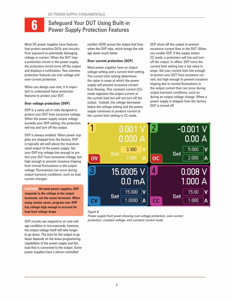
Figure 8:
Power supply front panel showing over-voltage protection, over-current
protection, constant voltage, and constant current mode
6DC POWER SUPPLY FUNDAMENTALS
9
Although you may expect your power
supply output to be completely open
when you set an “output off” state, this
may not be the case. When set to “off,”
the output impedance will vary from
model to model and may depend upon the
options installed in the power supply. The
“output off” state will typically set the
output voltage and output current to zero
and disable the internal power-generating
circuitry. However, these settings do not
guarantee that no current will flow into
or out of your DUT, as would be the case
if the output terminals were physically
disconnected from your DUT.
When the power supply output is “off”
but not completely open, your DUT test
could be adversely affected for a number
of reasons:
• Your DUT contains a source of DC
power that is connected directly
across the power supply output.
• Your DUT contains a source of DC
power that is connected across the
output in a reverse-polarity configura-
tion.
• Your DUT is sensitive to extra capaci-
tive loading.
• Your DUT produces a changing voltage
across the power supply output.
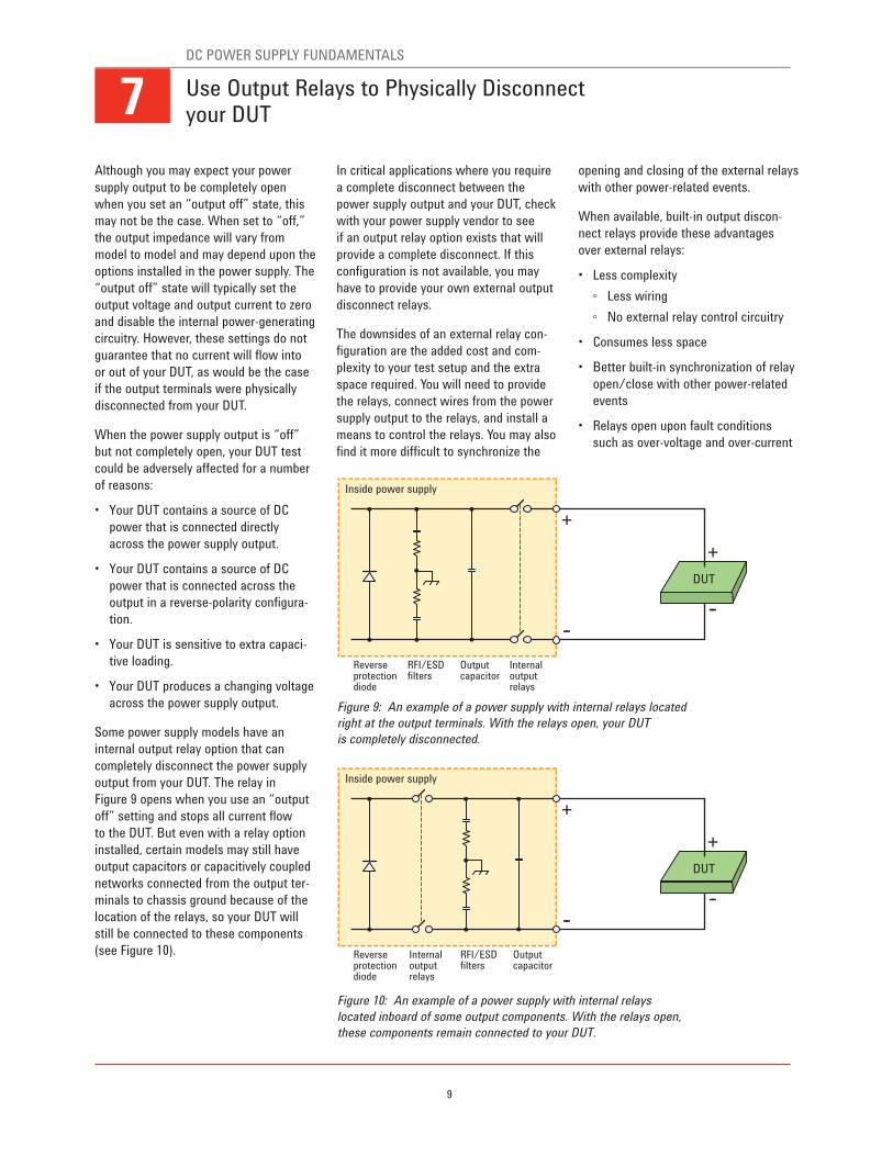
Some power supply models have an
internal output relay option that can
completely disconnect the power supply
output from your DUT. The relay in
Figure 9 opens when you use an “output
off” setting and stops all current flow
to the DUT. But even with a relay option
installed, certain models may still have
output capacitors or capacitively coupled
networks connected from the output ter-
minals to chassis ground because of the
location of the relays, so your DUT will
still be connected to these components
(see Figure 10).
In critical applications where you require
a complete disconnect between the
power supply output and your DUT, check
with your power supply vendor to see
if an output relay option exists that will
provide a complete disconnect. If this
configuration is not available, you may
have to provide your own external output
disconnect relays.
The downsides of an external relay con-
figuration are the added cost and com-
plexity to your test setup and the extra
space required. You will need to provide
the relays, connect wires from the power
supply output to the relays, and install a
means to control the relays. You may also
find it more difficult to synchronize the
opening and closing of the external relays
with other power-related events.
When available, built-in output discon-
nect relays provide these advantages
over external relays:
• Less complexity
Less wiring
No external relay control circuitry
• Consumes less space
• Better built-in synchronization of relay
open/close with other power-related
events
• Relays open upon fault conditions
such as over-voltage and over-current
Reverseprotectiondiode
Inside power supply
RFI/ESDfilters
Internaloutputrelays
Outputcapacitor
+
+
----
DUT
Reverseprotectiondiode
Inside power supply
RFI/ESDfilters
Internaloutputrelays
Outputcapacitor
+
+
----
DUT
Use Output Relays to Physically Disconnect your DUT
Figure 9: An example of a power supply with internal relays located
right at the output terminals. With the relays open, your DUT
is completely disconnected.
Figure 10: An example of a power supply with internal relays
located inboard of some output components. With the relays open,
these components remain connected to your DUT.
7DC POWER SUPPLY FUNDAMENTALS
10
While most power supplies can measure
DUT steady-state voltage and current,
some power supplies can also measure
dynamic voltage and current. These sup-
plies feature a built-in digitizer.
Traditionally, digitizers are used for data
acquisition to capture and store analog
signals. Like an oscilloscope, which uses
a digitizer to display the analog signal
present on one of its inputs, a power
supply’s built-in digitizer captures the
dynamic voltage and current waveforms
produced on its output.
Basic digitizer operation
Figure 11 shows a digitizer converting
an analog waveform into a set of data
points. Upon a trigger, the digitizer takes
measurement samples and stores them
in a buffer.
When you make a digitizing measure-
ment, you can set two of the following
three parameters:
• Time interval – time between samples
• Number of samples – total number
of samples you want to take
• Acquisition time – total time during
which you want to take samples
When two parameters are set, the
remaining parameter will be determined
by the following equation:
Acquisition time = Time interval x
(Number of samples --1)
In a similar manner, a power supply’s
built-in digitizer can be configured to
trigger and capture power supply output
voltage or current waveforms. The
supply’s digitizer will store a buffer of
readings with the waveform data points.
You can retrieve the data and use any
standard software for analysis. You also
can use your own customized program
or available device characterization soft-
ware to easily visualize the results in the
time domain (oscilloscope-like view or
data-logger view) or perform a statistical
analysis.
An example digitizer application
If you use your power supply in place of a
battery, you can capture dynamic informa-
tion about the current flowing into your
DUT, allowing you to better understand
the current drain on your DUT batteries.
Consequently, you can make appropriate
design adjustments to optimize your DUT
power management during the DUT’s
various modes of operation.
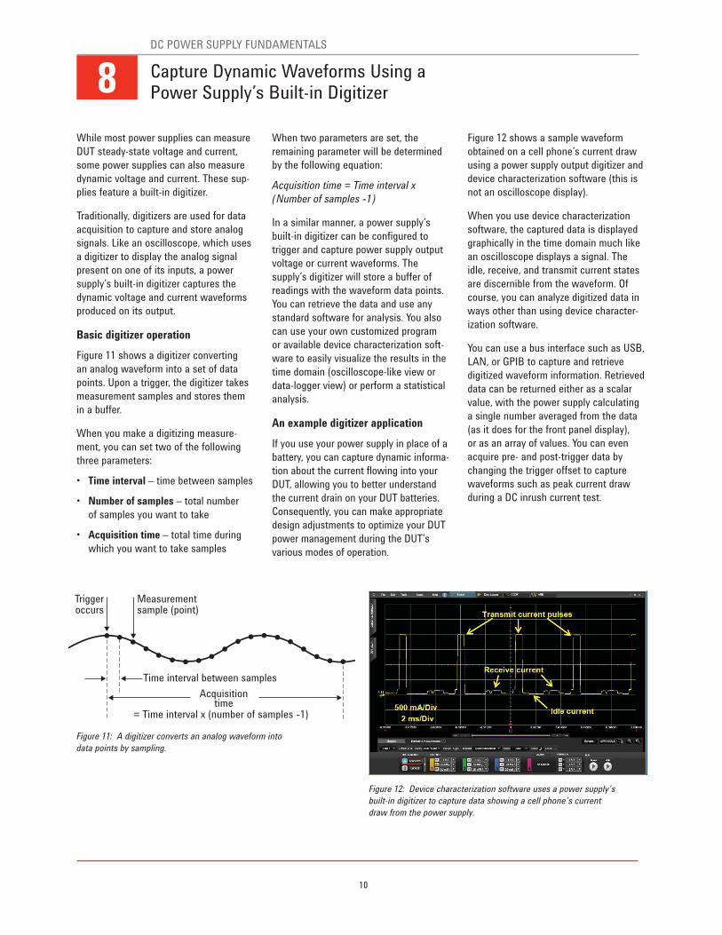
Figure 12 shows a sample waveform
obtained on a cell phone’s current draw
using a power supply output digitizer and
device characterization software (this is
not an oscilloscope display).
When you use device characterization
software, the captured data is displayed
graphically in the time domain much like
an oscilloscope displays a signal. The
idle, receive, and transmit current states
are discernible from the waveform. Of
course, you can analyze digitized data in
ways other than using device character-
ization software.
You can use a bus interface such as USB,
LAN, or GPIB to capture and retrieve
digitized waveform information. Retrieved
data can be returned either as a scalar
value, with the power supply calculating
a single number averaged from the data
(as it does for the front panel display),
or as an array of values. You can even
acquire pre- and post-trigger data by
changing the trigger offset to capture
waveforms such as peak current draw
during a DC inrush current test.
Capture Dynamic Waveforms Using a Power Supply’s Built-in Digitizer
Triggeroccurs
Measurementsample (point)
Time interval between samples
Acquisitiontime
= Time interval x (number of samples --1)
Figure 11: A digitizer converts an analog waveform into
data points by sampling.
Figure 12: Device characterization software uses a power supply’s
built-in digitizer to capture data showing a cell phone’s current
draw from the power supply.
8DC POWER SUPPLY FUNDAMENTALS
11
Typically, power supplies are used to bias
circuits that require a constant voltage.
However, more advanced applications
may require a time-varying voltage (or
current). Modern power supplies can
easily manage both using list mode to
address the time-varying applications.
What is list mode?
Normally, you can program a PC to
change the voltages on a power supply
output for discrete periods of time. In this
way, your program controls the transi-
tions between voltages to allow you to
test your DUT at different volt ages.
List mode lets you generate these voltage
sequences and synchronize them to
internal or external signals without tying
up the computer. You set individually
programmed steps of voltage (or current),
and an associated step duration. After
setting the duration for each step, you
trigger the list to execute directly on the
power supply. You may set the power
supply to move on to the next step based
on dwell times or triggers. A list can be
programmed to repeat once or multiple
times (see Figure 13).
To create a list, set the following:
• One or more voltage or current steps
– defined voltage or current values
• Dwell times – duration associated
with each voltage or current step
• Repeat count – the number of times
you want the list to repeat
Two uses of list mode for testing
The list mode on a power supply can be
an effective tool for running two types
of tests:
• Voltage sequence test – a test where
measurements are taken while the
DUT is exposed to discrete stimulus
voltage values.
• Voltage waveform test – a test where
measurements are taken while the
DUT is exposed to a stimulus voltage
waveform.
In both cases, the stimulus involves
creating a sequence of voltage steps.
The first has multiple levels of steady-
state voltages and the second has a
continuously varying voltage profile. The
two tests are commonly used for DUT
design verification. Be aware that DC
power supplies are limited in bandwidth
and typically can generate voltage wave-
forms only at frequencies up to tens of
kilohertz. Also, most power supplies are
unipolar devices that create only positive
voltages.
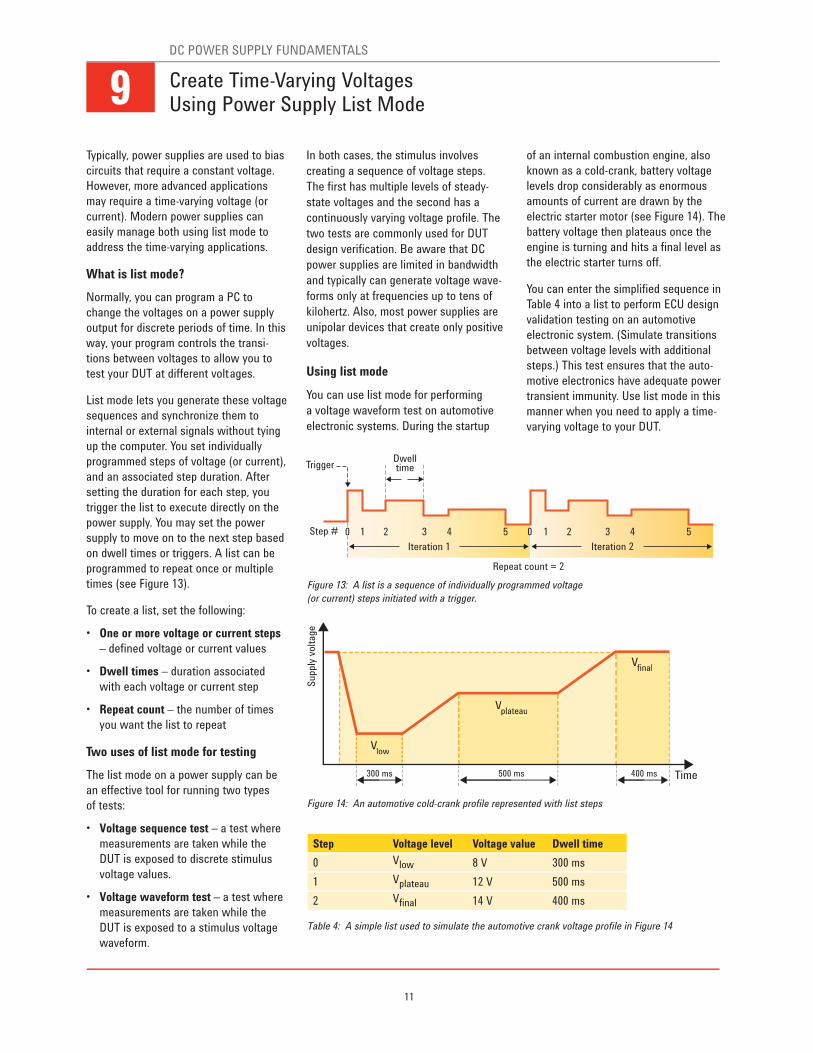
Using list mode
You can use list mode for performing
a voltage waveform test on automotive
electronic systems. During the startup
of an internal combustion engine, also
known as a cold-crank, battery voltage
levels drop considerably as enormous
amounts of current are drawn by the
electric starter motor (see Figure 14). The
battery voltage then plateaus once the
engine is turning and hits a final level as
the electric starter turns off.
You can enter the simplified sequence in
Table 4 into a list to perform ECU design
validation testing on an automotive
electronic system. (Simulate transitions
between voltage levels with additional
steps.) This test ensures that the auto-
motive electronics have adequate power
transient immunity. Use list mode in this
manner when you need to apply a time-
varying voltage to your DUT.
Create Time-Varying Voltages Using Power Supply List Mode
Figure 13: A list is a sequence of individually programmed voltage
(or current) steps initiated with a trigger.
Figure 14: An automotive cold-crank profile represented with list steps
Table 4: A simple list used to simulate the automotive crank voltage profile in Figure 14
Step Voltage level Voltage value Dwell time
0 Vlow 8 V 300 ms
1 Vplateau 12 V 500 ms
2 Vfinal 14 V 400 ms
Trigger
Step # 0 1 2 3 4 5
Dwelltime
Iteration 1
0 1 2 3 4 5
Iteration 2
Repeat count = 2
Supp
ly v
olt
age
Vlow
Vfinal
V
Time
plateau
300 ms 400 ms500 ms
Vlow
VV
Vplateau
V
Vfinal
V
9DC POWER SUPPLY FUNDAMENTALS
12
When you are planning out a test rack,
selecting an instrumentation layout can
be a challenging task. Safety, reliability,
and performance are among the many
requirements that affect your choices.
Specifically, pay attention to these
considerations when you put your DC
power supply in a rack:
• Weight distribution
Distribute weight properly to avoid
rack instability
• AC input power
Provide adequate AC input power
to avoid excessive current draw
• Heat management
Provide proper heat management
to avoid excessive temperatures
• Magnetic interference
Place instruments properly to minimize
magnetic interference
• Routing wires
Route wires to minimize conducted
and radiated noise
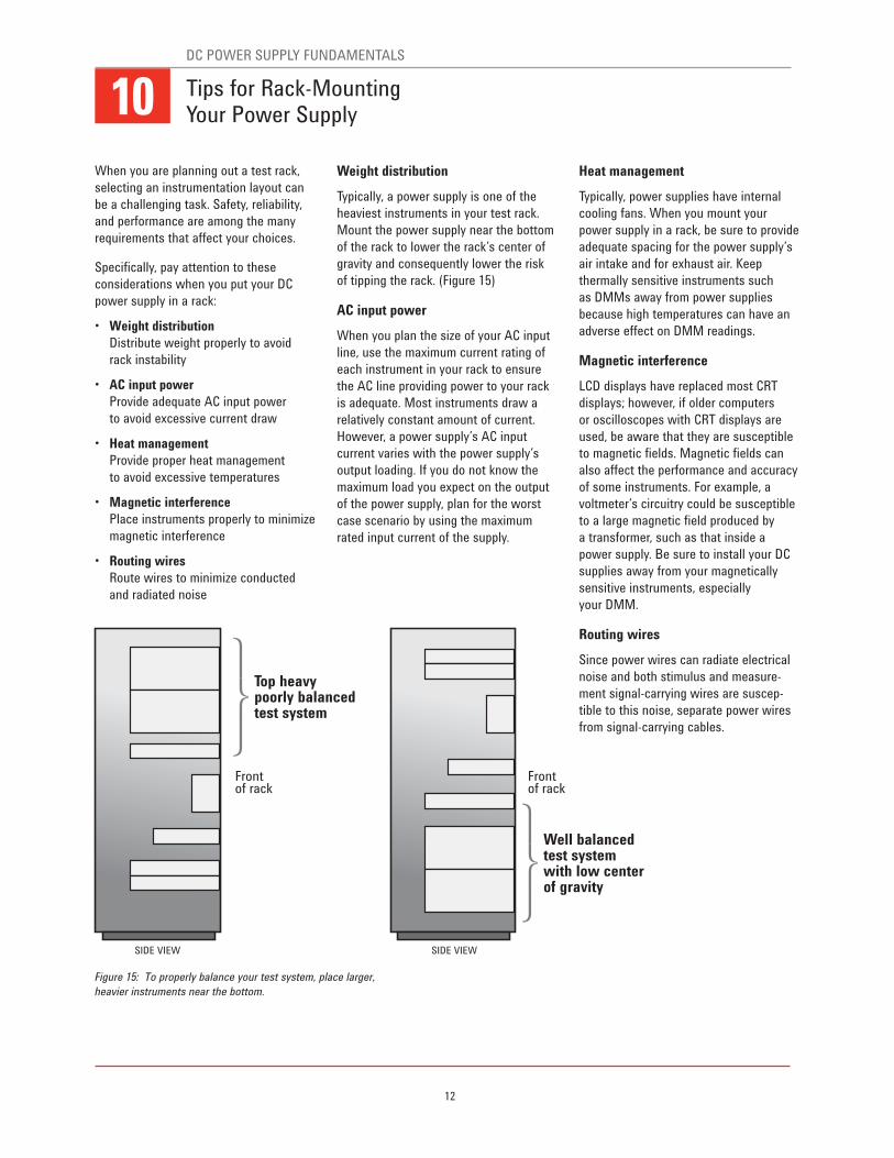
Weight distribution
Typically, a power supply is one of the
heaviest instruments in your test rack.
Mount the power supply near the bottom
of the rack to lower the rack’s center of
gravity and consequently lower the risk
of tipping the rack. (Figure 15)
AC input power
When you plan the size of your AC input
line, use the maximum current rating of
each instrument in your rack to ensure
the AC line providing power to your rack
is adequate. Most instruments draw a
relatively constant amount of current.
However, a power supply’s AC input
current varies with the power supply’s
output loading. If you do not know the
maximum load you expect on the output
of the power supply, plan for the worst
case scenario by using the maximum
rated input current of the supply.
Heat management
Typically, power supplies have internal
cooling fans. When you mount your
power supply in a rack, be sure to provide
adequate spacing for the power supply’s
air intake and for exhaust air. Keep
thermally sensitive instruments such
as DMMs away from power supplies
because high temperatures can have an
adverse effect on DMM readings.
Magnetic interference
LCD displays have replaced most CRT
displays; however, if older computers
or oscilloscopes with CRT displays are
used, be aware that they are susceptible
to magnetic fields. Magnetic fields can
also affect the performance and accuracy
of some instruments. For example, a
voltmeter’s circuitry could be susceptible
to a large magnetic field produced by
a transformer, such as that inside a
power supply. Be sure to install your DC
supplies away from your magnetically
sensitive instruments, especially
your DMM.
Routing wires
Since power wires can radiate electrical
noise and both stimulus and measure-
ment signal-carrying wires are suscep-
tible to this noise, separate power wires
from signal-carrying cables.
Top heavypoorly balancedtest system
Well balancedtest system with low centerof gravity
Front of rack
Front of rack
SIDE VIEW SIDE VIEW
Tips for Rack-Mounting Your Power Supply
Figure 15: To properly balance your test system, place larger,
heavier instruments near the bottom.
10DC POWER SUPPLY FUNDAMENTALS
13
Down programmingWhen a power supply with current sink capability is programmed to a voltage level less
than that of the voltage at the output terminals, the supply will automatically begin
to sink current. The downprogrammer can be thought of as an internal load across the
power supply’s output terminals that helps bring the output voltage down quickly.
DUTDevice under test
Linear-regulated power supplyA power supply design technique consisting of placing a control element in series
with the full-wave bridge rectifier and the outputs. Simplified, the control element can
be thought of as a variable resistor controlled by a feedback circuit that monitors the
output and adjusts the resistance accordingly to keep the output voltage constant.
RFI/ESD filtersRFI (radio-frequency interference) filters prevent undesired behavior from power supply
by providing a path to ground for noise current to flow. Similarly, ESD (electrostatic
discharge) filters prevent damage to your power supply by providing a path to ground
for static electricity to discharge.
Self-heating effects (shunt)Current flowing through a shunt resistor dissipates power (I2 x R) and heats up
the shunt causing a change in the resistance value.
SCR (silicon controlled rectifier)An SCR placed across the output terminals of a DC power supply creates a direct
short-circuit on the output of the supply when an over-voltage condition is detected.
Also known as a “crowbar,” this over-voltage protection prevents excessive
voltage from the reaching the load.
Switching-regulated power supplyA power supply design technique that uses a regulating element that acts like a rapidly
opened and closed switch. The duty cycle, or the ratio of time that the switches are
open or closed, is controlled by a feedback circuit. This circuit monitors the output and
adjusts the duty cycle to keep the output voltage constant.
Thermal EMF (thermal electromotive force)Thermoelectric voltages are generated when you make circuit connections with
dissimilar metals at different temperatures. This occurs because any metal-to-metal
junction forms a thermocouple, which generates voltage proportional to the junction
temperature. These junctions occur anywhere you connect metal leads, such as
at the DUT, at the relay, and to the multimeter.
Voltage/current ratingThe specified maximum voltage or current output that a power supply can produce.
Glossary

14
15
Related Agilent Literature
“10 Hints For Using Your Power Supply to Decrease Test Time” 5968-6359E
http://cp.literature.agilent.com/litweb/pdf/5968-6359E.pdf
“10 Practical Tips You Need to Know About Your Power Products” 5965-8239E
http://cp.literature.agilent.com/litweb/pdf/5965-8239E.pdf
“Understanding Linear Power Supply Operation” 5989-2291EN
http://cp.literature.agilent.com/litweb/pdf/5989-2291EN.pdf
“Test-System Development Guide” 5989-5367EN
http://cp.literature.agilent.com/litweb/pdf/5989-5367EN.pdf
Resources
Agilent Email Updates
www.agilent.com/find/emailupdates
Get the latest information on the
products and applications you select.
www.lxistandard.org
LAN eXtensions for Instruments puts
the power of Ethernet and the Web
inside your test systems. Agilent
is a founding member of the LXI
consortium.
Agilent Channel Partners
www.agilent.com/find/channelpartners
Get the best of both worlds: Agilent’s
measurement expertise and product
breadth, combined with channel
partner convenience.
For more information on Agilent Technologies’ products, applications or services, please contact your local Agilent
office. The complete list is available at:
www.agilent.com/find/contactus
AmericasCanada (877) 894 4414
Brazil (11) 4197 3600
Mexico 01800 5064 800
United States (800) 829 4444
Asia PacificAustralia 1 800 629 485
China 800 810 0189
Hong Kong 800 938 693
India 1 800 112 929
Japan 0120 (421) 345
Korea 080 769 0800
Malaysia 1 800 888 848
Singapore 1 800 375 8100
Taiwan 0800 047 866
Other AP Countries (65) 375 8100
Europe & Middle EastBelgium 32 (0) 2 404 93 40
Denmark 45 45 80 12 15
Finland 358 (0) 10 855 2100
France 0825 010 700*
*0.125 €/minute
Germany 49 (0) 7031 464 6333
Ireland 1890 924 204
Israel 972-3-9288-504/544
Italy 39 02 92 60 8484
Netherlands 31 (0) 20 547 2111
Spain 34 (91) 631 3300
Sweden 0200-88 22 55
United Kingdom 44 (0) 118 927 6201
For other unlisted countries: www.agilent.com/find/contactusRevised: January 6, 2012
Product specifications and descriptions
in this document subject to change
without notice.
© Agilent Technologies, Inc. 2012
Published in USA, April 25, 2012
5990-8888EN
www.agilent.comwww.agilent.com/find/power
Agilent Advantage Services is committed
to your success throughout your equip-
ment’s lifetime. To keep you competitive,
we continually invest in tools and
processes that speed up calibration and
repair and reduce your cost of ownership.
You can also use Infoline Web Services
to manage equipment and services more
effectively. By sharing our measurement
and service expertise, we help you create
the products that change our world.
www.agilent.com/quality
www.agilent.com/find/advantageservices
www.axiestandard.org
AdvancedTCA® Extensions for
Instrumentation and Test (AXIe) is
an open standard that extends the
AdvancedTCA for general purpose
and semiconductor test. Agilent
is a founding member of the AXIe
consortium.
www.pxisa.org
PCI eXtensions for Instrumentation
(PXI) modular instrumentation
delivers a rugged, PC-based high-
performance measurement and
automation system.