template attributes reference guide - tekla · pdf filetekla structures template attributes...
TRANSCRIPT

Tekla StructuresTemplate AttributesReference Guide
Product version 21.0March 2015
©2015 Tekla Corporation

Contents
1 Template Attributes Reference Guide ..........................................................111.1 A............................................................................................................................................... 11
ACN ....................................................................................................................................................................................11 ACTIVE_DESIGN_CODE ................................................................................................................................................ 11 ADDRESS ..........................................................................................................................................................................11 ALIAS_NAME1 ... 3 ........................................................................................................................................................ 12 ANG_S, ANG_T, ANG_U, ANG_V ...............................................................................................................................12 ANG_U_MAX, ANG_U_MIN, ANG_V_MAX, ANG_V_MIN .................................................................................12APPROVED_BY.................................................................................................................................................................. 12 AREA ..................................................................................................................................................................................13 AREA_FORM_TOP, AREA_FORM_BOTTOM, AREA_FORM_SIDE .......................................................................13 AREA_GROSS .................................................................................................................................................................. 14 AREA_NET ........................................................................................................................................................................14 AREA_PER_TONS ........................................................................................................................................................... 14 AREA_PGX, AREA_NGX, AREA_PGY, AREA_NGY, AREA_PGZ, AREA_NGZ ................................................... 14 AREA_PLAN .....................................................................................................................................................................14 AREA_PROJECTION_GXY_GROSS, AREA_PROJECTION_GXZ_GROSS,AREA_PROJECTION_GYZ_GROSS ...............................................................................................................................15 AREA_PROJECTION_GXY_NET, AREA_PROJECTION_GXZ_NET, AREA_PROJECTION_GYZ_NET ............. 15 AREA_PROJECTION_XY_GROSS, AREA_PROJECTION_XZ_GROSS, AREA_PROJECTION_YZ_GROSS .....15 AREA_PROJECTION_XY_NET, AREA_PROJECTION_XZ_NET, AREA_PROJECTION_YZ_NET ...................... 15 AREA_PX, AREA_NX, AREA_PY, AREA_NY, AREA_PZ, AREA_NZ .....................................................................16 ASSEMBLY_BOTTOM_LEVEL .......................................................................................................................................16ASSEMBLY_BOTTOM_LEVEL_GLOBAL........................................................................................................................16ASSEMBLY_BOTTOM_LEVEL_GLOBAL_UNFORMATTED........................................................................................ 17 ASSEMBLY_BOTTOM_LEVEL_UNFORMATTED ....................................................................................................... 17ASSEMBLY_DEFAULT_PREFIX.......................................................................................................................................17 ASSEMBLY_PLWEIGHT .................................................................................................................................................17 ASSEMBLY_POS ............................................................................................................................................................. 17 ASSEMBLY_POSITION_CODE ......................................................................................................................................18 ASSEMBLY_PREFIX ........................................................................................................................................................19 ASSEMBLY_SERIAL_NUMBER ....................................................................................................................................19ASSEMBLY_START_NUMBER........................................................................................................................................19 ASSEMBLY_TOP_LEVEL ................................................................................................................................................ 19ASSEMBLY_TOP_LEVEL_GLOBAL.................................................................................................................................20ASSEMBLY_TOP_LEVEL_GLOBAL_UNFORMATTED................................................................................................. 20 ASSEMBLY_TOP_LEVEL_UNFORMATTED ................................................................................................................ 20axial1, axial2..................................................................................................................................................................... 21
1.2 B............................................................................................................................................... 21 BOLT_EDGE_DISTANCE ................................................................................................................................................ 21 BOLT_EDGE_DISTANCE_MIN ..................................................................................................................................... 21BOLT_FULL_NAME........................................................................................................................................................... 22 BOLT_MATERIAL_LENGTH ...........................................................................................................................................22 BOLT_NPARTS .................................................................................................................................................................22BOLT_SHORT_NAME....................................................................................................................................................... 23 BOLT_STANDARD ...........................................................................................................................................................23
2
BOTTOM_LEVEL .............................................................................................................................................................. 23BOTTOM_LEVEL_GLOBAL............................................................................................................................................... 23BOTTOM_LEVEL_GLOBAL_UNFORMATTED............................................................................................................... 23 BOTTOM_LEVEL_UNFORMATTED .............................................................................................................................. 24BOUNDING_BOX_xxx..................................................................................................................................................... 24 BUILDER ........................................................................................................................................................................... 24
1.3 C............................................................................................................................................... 25cambering.......................................................................................................................................................................... 25 CANTILEVER .....................................................................................................................................................................25 CAST_UNIT_BOTTOM_LEVEL ...................................................................................................................................... 25CAST_UNIT_HEIGHT_ONLY_CONCRETE_PARTS......................................................................................................25CAST_UNIT_HEIGHT_ONLY_PARTS.............................................................................................................................25CAST_UNIT_HEIGHT_TOTAL.......................................................................................................................................... 26CAST_UNIT_LENGTH_ONLY_CONCRETE_PARTS..................................................................................................... 26CAST_UNIT_LENGTH_ONLY_PARTS............................................................................................................................26CAST_UNIT_LENGTH_TOTAL......................................................................................................................................... 26 CAST_UNIT_POS ............................................................................................................................................................ 26 CAST_UNIT_POSITION_CODE .....................................................................................................................................26 CAST_UNIT_PREFIX .......................................................................................................................................................26CAST_UNIT_REBAR_WEIGHT........................................................................................................................................27 CAST_UNIT_SERIAL_NUMBER ...................................................................................................................................27 CAST_UNIT_TOP_LEVEL ............................................................................................................................................... 27CAST_UNIT_TYPE..............................................................................................................................................................27CAST_UNIT_VERTICAL_POSITION_CODE...................................................................................................................27CAST_UNIT_WIDTH_ONLY_CONCRETE_PARTS....................................................................................................... 27CAST_UNIT_WIDTH_ONLY_PARTS.............................................................................................................................. 28CAST_UNIT_WIDTH_TOTAL........................................................................................................................................... 28 CATALOG_NAME ............................................................................................................................................................28 CC .......................................................................................................................................................................................28 CC_CROSS ....................................................................................................................................................................... 28 CC_EXACT ........................................................................................................................................................................ 28 CC_EXACT_CROSS .........................................................................................................................................................28 CC_EXACT_LONG ...........................................................................................................................................................28 CC_LONG ......................................................................................................................................................................... 29 CC_MAX ........................................................................................................................................................................... 29 CC_MAX_CROSS ............................................................................................................................................................29 CC_MAX_LONG ..............................................................................................................................................................29 CC_MIN ............................................................................................................................................................................29 CC_MIN_CROSS .............................................................................................................................................................29 CC_MIN_LONG ...............................................................................................................................................................29CHECKED_BY.....................................................................................................................................................................30CHECKED_DATE................................................................................................................................................................ 30 CLASS ................................................................................................................................................................................30 CLASS_ATTR .................................................................................................................................................................... 30 CODE ................................................................................................................................................................................. 30 COG_X, COG_Y, COG_Z ............................................................................................................................................... 30 comment ..........................................................................................................................................................................31CONN_CODE_END1, CONN_CODE_END2.................................................................................................................31 CONNECTED_ASSEMBLIES ..........................................................................................................................................31 CONNECTED_PARTS ......................................................................................................................................................31 CONNECTION_CODE ..................................................................................................................................................... 31 CONNECTION_DSTV ......................................................................................................................................................31 CONNECTION_ERROR ...................................................................................................................................................32 CONNECTION_GROUP ..................................................................................................................................................32 CONNECTION_NUMBER .............................................................................................................................................. 32
3

CONNECTION_RUNNING_NUMBER .........................................................................................................................32 CONTENTTYPE .................................................................................................................................................................32 COVER_AREA .................................................................................................................................................................. 32CREATED_BY......................................................................................................................................................................33 CROSS_SECTION_AREA ............................................................................................................................................... 33 CURRENT_PHASE ...........................................................................................................................................................33CURVED_SEGMENTS....................................................................................................................................................... 33CUSTOM.HC_xxx.............................................................................................................................................................. 33CUSTOM.WALL_xxx......................................................................................................................................................... 34
1.4 D............................................................................................................................................... 34 DATE .................................................................................................................................................................................. 34DATE_APPROVED..............................................................................................................................................................34DATE_CHECKED................................................................................................................................................................ 34 DATE_CREATE ................................................................................................................................................................. 35 DATE_END ........................................................................................................................................................................35 DATE_ISSUE .....................................................................................................................................................................35 DATE_LAST .......................................................................................................................................................................35 DATE_MODIFY ................................................................................................................................................................ 35 DATE_PLOT ...................................................................................................................................................................... 35 DATE_START .................................................................................................................................................................... 36DELIVERY............................................................................................................................................................................ 36DESCRIPTION.....................................................................................................................................................................36 DESIGNER ........................................................................................................................................................................ 36DesignGroup...................................................................................................................................................................... 36 DIAMETER ........................................................................................................................................................................ 36 DIAMETER_1, DIAMETER_2 ........................................................................................................................................ 37 DIAMETER_X ................................................................................................................................................................... 37 DIAMETER_Y ................................................................................................................................................................... 37 DIM_A ... DIM_G, DIM_H1, DIM_H2, DIM_I, DIM_J, DIM_K1, DIM_K2, DIM_L, DIM_O,DIM_R, DIM_R_ALL, DIM_TD, DIM_WEIGHT, DIM_X, DIM_Y ............................................................................37 DIM_A_MAX ... DIM_G_MAX, DIM_H1_MAX, DIM_H2_MAX, DIM_I_MAX, DIM_J_MAX,DIM_K1_MAX, DIM_K2_MAX, DIM_O_MAX, DIM_R_MAX, DIM_TD_MAX, DIM_X_MAX,DIM_Y_MAX .....................................................................................................................................................................38 DIM_A_MIN ... DIM_G_MIN, DIM_H1_MIN, DIM_H2_MIN, DIM_I_MIN, DIM_J_MIN,DIM_K1_MIN, DIM_K2_MIN, DIM_O_MIN, DIM_R_MIN, DIM_TD_MIN, DIM_X_MIN,DIM_Y_MIN ......................................................................................................................................................................38DRAWING_USERFIELD_1 ... _8.....................................................................................................................................38 DR_DEFAULT_HOLE_SIZE ............................................................................................................................................38 DR_DEFAULT_WELD_SIZE ...........................................................................................................................................39 DR_PART_POS ................................................................................................................................................................ 39
1.5 E................................................................................................................................................39 ECCENTRICITY_X, ECCENTRICITY_Y ..........................................................................................................................39 EDGE_FOLD, EDGE_FOLD_1, EDGE_FOLD_2 .......................................................................................................... 39 END_X, END_Y, END_Z ................................................................................................................................................ 40 END1_ANGLE_Z ............................................................................................................................................................. 40 END1_ANGLE_Y ............................................................................................................................................................. 40 END2_ANGLE_Z ............................................................................................................................................................. 40 END2_ANGLE_Y ............................................................................................................................................................. 40 END1_CODE, END2_CODE .......................................................................................................................................... 40 END1_SKEW, END2_SKEW ......................................................................................................................................... 41ERECTIONSTATUS............................................................................................................................................................. 41EXTRA_LENGTH.................................................................................................................................................................41
1.6 F................................................................................................................................................41fabricator............................................................................................................................................................................41
4

FATHER_ID .......................................................................................................................................................................41 FINISH ...............................................................................................................................................................................41 FLANGE_LENGTH_B ...................................................................................................................................................... 42 FLANGE_LENGTH_U ......................................................................................................................................................42 FLANGE_SLOPE_RATIO .................................................................................................................................................42 FLANGE_THICKNESS .....................................................................................................................................................42 FLANGE_THICKNESS_1, FLANGE_THICKNESS_2 ..................................................................................................42 FLANGE_THICKNESS_B ................................................................................................................................................42 FLANGE_THICKNESS_U ................................................................................................................................................43 FLANGE_WIDTH ............................................................................................................................................................. 43 FLANGE_WIDTH_1, FLANGE_WIDTH_2 ...................................................................................................................43 FLANGE_WIDTH_B ........................................................................................................................................................ 43 FLANGE_WIDTH_U ........................................................................................................................................................43 FOLD_ANGLE ...................................................................................................................................................................43
1.7 G............................................................................................................................................... 44 GRADE ...............................................................................................................................................................................44 GROUP_TYPE ...................................................................................................................................................................44 GUID .................................................................................................................................................................................. 44
1.8 H............................................................................................................................................... 44HAS_CONNECTIONS........................................................................................................................................................44HAS_HOLES....................................................................................................................................................................... 44 HEAD_DIAMETER ...........................................................................................................................................................45 HEAD_THICKNESS ......................................................................................................................................................... 45 HEIGHT ..............................................................................................................................................................................45 HEIGHT_1 ... 4 .................................................................................................................................................................45HIERARCHY_LEVEL.......................................................................................................................................................... 45HISTORY..............................................................................................................................................................................46 HOLE_TOLERANCE .........................................................................................................................................................46HOOK_START, HOOK_END.............................................................................................................................................47HOOK_START_ANGLE, HOOK_END_ANGLE..............................................................................................................47HOOK_START_LENGTH, HOOK_END_LENGTH......................................................................................................... 47HOOK_START_RADIUS, HOOK_END_RADIUS.......................................................................................................... 47
1.9 I.................................................................................................................................................47 ID ........................................................................................................................................................................................47IFC_BUILDING................................................................................................................................................................... 47IFC_BUILDING_STOREY.................................................................................................................................................. 47IFC_ENTITY.........................................................................................................................................................................48IFC_SITE.............................................................................................................................................................................. 48 INFO1, INFO2 .................................................................................................................................................................. 48 INNER_DIAMETER ......................................................................................................................................................... 48INSTALL_ACTUAL..............................................................................................................................................................48INSTALL_PLAN.................................................................................................................................................................. 48IS_CONCEPTUAL...............................................................................................................................................................49IS_ITEM...............................................................................................................................................................................49IS_POLYBEAM................................................................................................................................................................... 49IS_POUR_BREAK_VALID.................................................................................................................................................49
1.10 L................................................................................................................................................49 LAST ...................................................................................................................................................................................49LAST_APPROVED_BY.......................................................................................................................................................49LAST_CHECKED_BY......................................................................................................................................................... 50LAST_CREATED_BY.......................................................................................................................................................... 50LAST_DATE_APPROVED.................................................................................................................................................. 50LAST_DATE_CHECKED.....................................................................................................................................................50LAST_DATE_CREATE........................................................................................................................................................ 50
5

LAST_DELIVERY.................................................................................................................................................................50LAST_DESCRIPTION......................................................................................................................................................... 50LAST_INFO1....................................................................................................................................................................... 50LAST_INFO2....................................................................................................................................................................... 51 LAST_MARK .....................................................................................................................................................................51 LAST_TEXT1...3 ................................................................................................................................................................51 LENGTH .............................................................................................................................................................................51 LENGTH_GROSS ............................................................................................................................................................. 51 LENGTH_MAX ................................................................................................................................................................. 51 LENGTH_MIN .................................................................................................................................................................. 51 LONG_HOLE_X ............................................................................................................................................................... 51 LONG_HOLE_Y ................................................................................................................................................................52 LOT_NUMBER ................................................................................................................................................................. 52 LOT_NAME .......................................................................................................................................................................52
1.11 M.............................................................................................................................................. 52 MAIN_PART .....................................................................................................................................................................52 MAJOR_AXIS_LENGTH_1 ... 2 .................................................................................................................................... 52 MARK ................................................................................................................................................................................ 53 MATERIAL ........................................................................................................................................................................ 53 MATERIAL_TYPE .............................................................................................................................................................53 MESH_POS ...................................................................................................................................................................... 53 MINOR_AXIS_LENGTH_1 ... 2 .................................................................................................................................... 53 MODEL .............................................................................................................................................................................. 53 MODEL_TOTAL ................................................................................................................................................................ 54 MODULUS_OF_ELASTICITY ......................................................................................................................................... 54 MOMENT_OF_INERTIA_X ............................................................................................................................................54 MOMENT_OF_INERTIA_Y ............................................................................................................................................54moment1, moment2........................................................................................................................................................54 MORTAR_VOLUME ........................................................................................................................................................ 54
1.12 N...............................................................................................................................................54 NAME ................................................................................................................................................................................55 NAME_BASE ....................................................................................................................................................................56 NEUTRAL_AXIS_LOCATION_ELASTIC_X .................................................................................................................. 56 NEUTRAL_AXIS_LOCATION_ELASTIC_Y .................................................................................................................. 56 NEUTRAL_AXIS_LOCATION_PLASTIC_X .................................................................................................................. 56 NEUTRAL_AXIS_LOCATION_PLASTIC_Y .................................................................................................................. 56 NORMALIZED_WARPING_CONSTANT ..................................................................................................................... 56 NUMBER, NUMBER#1, NUMBER #2 ....................................................................................................................... 57NUMBER_IN_PHASE(X)..................................................................................................................................................57NUMBER_OF_TILE_TYPES..............................................................................................................................................57NUMBER_VISIBLE............................................................................................................................................................ 57
1.13 O...............................................................................................................................................57 OBJECT ..............................................................................................................................................................................57 OBJECT_DESCRIPTION ..................................................................................................................................................58 OBJECT_LOCKED ............................................................................................................................................................ 58ORIGIN_X, ORIGIN_Y, ORIGIN_Z................................................................................................................................. 58 OBJECT_TYPE .................................................................................................................................................................. 59 OWNER .............................................................................................................................................................................59
1.14 P................................................................................................................................................59 PAGE ..................................................................................................................................................................................59 PART_POS ........................................................................................................................................................................ 59 PART_PREFIX ...................................................................................................................................................................60 PART_SERIAL_NUMBER ...............................................................................................................................................60PART_START_NUMBER...................................................................................................................................................60
6

PCS .....................................................................................................................................................................................60 PHASE ............................................................................................................................................................................... 60 PLASTIC_MODULUS_X ................................................................................................................................................. 60 PLASTIC_MODULUS_Y ..................................................................................................................................................60 PLATE_DENSITY ..............................................................................................................................................................61 PLATE_THICKNESS .........................................................................................................................................................61 PLOTFILE ........................................................................................................................................................................... 61 POISSONS_RATIO .......................................................................................................................................................... 61 POLAR_RADIUS_OF_GYRATION ................................................................................................................................ 61 PRELIM_MARK ............................................................................................................................................................... 61 PROFILE ............................................................................................................................................................................ 62 PROFILE_DENSITY ..........................................................................................................................................................62PROFILE_TYPE................................................................................................................................................................... 63 PROFILE_WEIGHT .......................................................................................................................................................... 63 PROFILE_WEIGHT_NET .................................................................................................................................................63PROJECT_COMMENT.......................................................................................................................................................64PROJECT_USERFIELD_1 ... 8.......................................................................................................................................... 64
1.15 R............................................................................................................................................... 64RADIUS................................................................................................................................................................................64 RADIUS_OF_GYRATION_X .......................................................................................................................................... 64 RADIUS_OF_GYRATION_Y ...........................................................................................................................................64REBAR_MESH_LEFT_OVERHANG_CROSS.................................................................................................................64REBAR_MESH_LEFT_OVERHANG_LONG...................................................................................................................65REBAR_MESH_RIGHT_OVERHANG_CROSS..............................................................................................................65REBAR_MESH_RIGHT_OVERHANG_LONG................................................................................................................65 REBAR_POS .....................................................................................................................................................................65REFERENCE_ASSEMBLY................................................................................................................................................. 65REFERENCE_MODEL........................................................................................................................................................ 67REFERENCE_MODEL_OBJECT....................................................................................................................................... 67 ROUNDING_RADIUS, ROUNDING_RADIUS_1 ... 2 ............................................................................................... 68 ROW_IN_PAGE ...............................................................................................................................................................68
1.16 S................................................................................................................................................68 SCALE1...5 ........................................................................................................................................................................ 68SCHED_FAB_DATE........................................................................................................................................................... 68SCREW_HOLE_DIAMETER_X.........................................................................................................................................68SCREW_HOLE_DIAMETER_Y.........................................................................................................................................69 SECTION_MODULUS_X, SECTION_MODULUS_Y .................................................................................................. 69 SHAPE ............................................................................................................................................................................... 69 SHAPE_INTERNAL ..........................................................................................................................................................69 SHEAR_CENTER_LOCATION ........................................................................................................................................69shear1, shear2...................................................................................................................................................................69SHOP_ISSUE...................................................................................................................................................................... 69SHOPSTATUS......................................................................................................................................................................70 SIMILAR_TO_MAIN_PART ...........................................................................................................................................70 SITE_WORKSHOP ...........................................................................................................................................................70 SIZE ....................................................................................................................................................................................70 SORT_OF_E_x_Cw_PER_G_x_J .................................................................................................................................70 SUPPLEMENT_PART_WEIGHT .................................................................................................................................... 71 START_X ........................................................................................................................................................................... 71 START_Y ........................................................................................................................................................................... 71 START_Z ........................................................................................................................................................................... 71 STATICAL_MOMENT_Qf ...............................................................................................................................................71 STATICAL_MOMENT_Qw .............................................................................................................................................71 STIFFENER_DIMENSION ...............................................................................................................................................71 STIFFENER_DIMENSION_1 ... 3 ..................................................................................................................................72
7
STRAND_DEBONDED_STRANDS_1...5........................................................................................................................ 72STRAND_DEBOND_LEN_FROM_END_1...5............................................................................................................... 72STRAND_DEBOND_LEN_FROM_START_1...5............................................................................................................72STRAND_DEBOND_LEN_MIDDLE_TO_END_1...5.................................................................................................... 73STRAND_DEBOND_LEN_MIDDLE_TO_START_1...5.................................................................................................73 STRAND_N_PATTERN ................................................................................................................................................... 73 STRAND_N_STRAND .....................................................................................................................................................73 STRAND_POS .................................................................................................................................................................. 73 STRAND_PULL_FORCE ..................................................................................................................................................73 STRAND_UNBONDED ................................................................................................................................................... 73 SUBTYPE ...........................................................................................................................................................................74 SURFACING_NAME .......................................................................................................................................................74
1.17 T................................................................................................................................................74 TANGENT_OF_PRINCIPAL_AXIS_ANGLE .................................................................................................................74 TEXT1...3 ........................................................................................................................................................................... 74 THERMAL_DILATATION ................................................................................................................................................ 74THICKNESS.........................................................................................................................................................................74 THREAD_IN_MATERIAL ................................................................................................................................................75 TILE_NUMBER .................................................................................................................................................................75 TILE_VOLUME ................................................................................................................................................................. 75 TIME ...................................................................................................................................................................................75 TITLE .................................................................................................................................................................................. 75 TITLE1...3 ...........................................................................................................................................................................75 TOP_LEVEL ....................................................................................................................................................................... 75TOP_LEVEL_GLOBAL........................................................................................................................................................ 76TOP_LEVEL_GLOBAL_UNFORMATTED........................................................................................................................ 76 TOP_LEVEL_UNFORMATTED ....................................................................................................................................... 76 TORSIONAL_CONSTANT ...............................................................................................................................................77 TYPE ...................................................................................................................................................................................77 TYPE1 ................................................................................................................................................................................ 77 TYPE2 ................................................................................................................................................................................ 77 TYPE3 ................................................................................................................................................................................ 77 TYPE4 ................................................................................................................................................................................ 78
1.18 U............................................................................................................................................... 78USER_PHASE..................................................................................................................................................................... 78 USERFIELD_1 ... _8 ........................................................................................................................................................ 78
1.19 V............................................................................................................................................... 78 VOLUME ........................................................................................................................................................................... 78 VOLUME_GROSS ............................................................................................................................................................78 VOLUME_NET ..................................................................................................................................................................78VOLUME_NET_ONLY_CONCRETE_PARTS..................................................................................................................79VOLUME_ONLY_CONCRETE_PARTS............................................................................................................................79
1.20 W..............................................................................................................................................79 WARPING_CONSTANT ..................................................................................................................................................79 WARPING_STATICAL_MOMENT ................................................................................................................................ 79 WEB_HEIGHT .................................................................................................................................................................. 79 WEB_LENGTH ................................................................................................................................................................. 79 WEB_THICKNESS ........................................................................................................................................................... 80 WEB_THICKNESS_1, WEB_THICKNESS_2 ..............................................................................................................80 WEB_WIDTH ................................................................................................................................................................... 80 WEIGHT ............................................................................................................................................................................ 80 WEIGHT_GROSS .............................................................................................................................................................81 WEIGHT_M ...................................................................................................................................................................... 81 WEIGHT_MAX .................................................................................................................................................................81
8

WEIGHT_MIN ..................................................................................................................................................................81 WEIGHT_NET ...................................................................................................................................................................81WEIGHT_NET_ONLY_CONCRETE_PARTS...................................................................................................................82WEIGHT_ONLY_CONCRETE_PARTS.............................................................................................................................82 WEIGHT_PER_UNIT_LENGTH ..................................................................................................................................... 82 WEIGHT_TOTAL .............................................................................................................................................................. 83WELD_ACTUAL_LENGTH1, WELD_ACTUAL_LENGTH2...........................................................................................83 WELD_ANGLE1, WELD_ANGLE2 ................................................................................................................................83 WELD_ASSEMBLYTYPE .................................................................................................................................................83 WELD_DEFAULT ..............................................................................................................................................................83WELD_CROSSSECTION_AREA1, WELD_CROSSSECTION_AREA2........................................................................83WELD_EDGE_AROUND................................................................................................................................................... 84WELD_EFFECTIVE_THROAT, WELD_EFFECTIVE_THROAT2.................................................................................... 84WELD_ELECTRODE_CLASSIFICATION......................................................................................................................... 84WELD_ELECTRODE_COEFFICIENT................................................................................................................................ 84WELD_ELECTRODE_STRENGTH.................................................................................................................................... 84WELD_ERRORLIST............................................................................................................................................................ 84 WELD_FATHER_CODE ...................................................................................................................................................85 WELD_FATHER_NUMBER ............................................................................................................................................85 WELD_FILLTYPE1, WELD_FILLTYPE2 .........................................................................................................................85 WELD_FINISH1, WELD_FINISH2 ............................................................................................................................... 85WELD_INCREMENT_AMOUNT1, WELD_INCREMENT_AMOUNT2......................................................................85WELD_INTERMITTENT_TYPE..........................................................................................................................................85WELD_LENGTH1 ... 2....................................................................................................................................................... 86WELD_NDT_INSPECTION............................................................................................................................................... 86WELD_NUMBER............................................................................................................................................................... 86WELD_PERIOD1 ... 2........................................................................................................................................................ 86WELD_POSITION...............................................................................................................................................................86WELD_POSITION_X..........................................................................................................................................................86WELD_POSITION_Y..........................................................................................................................................................87WELD_POSITION_Z..........................................................................................................................................................87WELD_PROCESS_TYPE....................................................................................................................................................87 WELD_ROOT_FACE_THICKNESS, WELD_ROOT_FACE_THICKNESS2 ...............................................................87WELD_ROOT_OPENING, WELD_ROOT_OPENING2.................................................................................................87 WELD_SIZE1, WELD_SIZE2 ......................................................................................................................................... 87WELD_SIZE_PREFIX_ABOVE..........................................................................................................................................87WELD_SIZE_PREFIX_BELOW.........................................................................................................................................88 WELD_TEXT ......................................................................................................................................................................88 WELD_TYPE1, WELD_TYPE2 ....................................................................................................................................... 88WELD_VOLUME................................................................................................................................................................ 88 WIDTH ...............................................................................................................................................................................88 WIDTH_1, WIDTH_2 ......................................................................................................................................................88
1.21 X............................................................................................................................................... 89xs_shorten..........................................................................................................................................................................89
2 Disclaimer.........................................................................................................90
9

10
1 Template Attributes Reference Guide
You can use template fields in drawing and report templates. When you open a drawing orcreate a report, Tekla Structures uses the attributes and formulas to calculate and displayinformation from the model database. This could, for example, include assembly weight orcover area.
Descriptions of template attributes are listed in alphabetical order. Expand the table ofcontents to browse the template attributes.
1.1 A
ACNShows control numbers.
For more information on control numbers, see and .
ACTIVE_DESIGN_CODEShows the active design code of material.
ADDRESSShows the address entered in the Project properties dialog box.
See also
Template Attributes Reference Guide 11 A

ALIAS_NAME1 ... 3Alias name of the material.
Use for part and main part material attributes in ASSEMBLY and PART content types.
ANG_S, ANG_T, ANG_U, ANG_VShow bending angles of reinforcing bars based on the mappings in therebar_schedule_config.inp file, located in the ..\ProgramData\TeklaStructures\<version>\environments\<environment>\system folder.These mappings are environment-specific by default. You can modify them to suit yourcompany or project needs.
Creating a template for bending schedules or pull-outs
Hard-coded bending type identifiers in reinforcement shape recognition
ANG_U_MAX, ANG_U_MIN, ANG_V_MAX, ANG_V_MIN on page 12
DIM_A ... DIM_G, DIM_H1, DIM_H2, DIM_I, DIM_J, DIM_K1, DIM_K2, DIM_L, DIM_O, DIM_R,DIM_R_ALL, DIM_TD, DIM_WEIGHT, DIM_X, DIM_Y on page 37
ANG_U_MAX, ANG_U_MIN, ANG_V_MAX, ANG_V_MINShows the minimum and maximum bending angles of reinforcing bars or meshes in taperedcross sections. See the example below:
APPROVED_BY
The Approved by information of the revision from the Revision Handling dialog box.
See also
Template Attributes Reference Guide 12 A
AREAShows the following information:
• For plate type catalog profiles, any parametric profiles and any catalog profiles withCover area property not defined, shows the total net area of all surfaces.
• For other types of catalog profiles with Cover area property defined, shows the grosstotal surface area.
The area is calculated using the extreme length and profile cover area per meter (valuedefined in the profile catalog). The cross area on profile ends, cuts and fittings are nottaken into account.
AREA_GROSS on page 13
AREA_NET on page 14
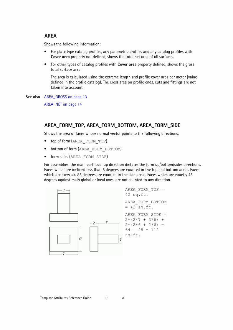
AREA_FORM_TOP, AREA_FORM_BOTTOM, AREA_FORM_SIDEShows the area of faces whose normal vector points to the following directions:
• top of form (AREA_FORM_TOP)
• bottom of form (AREA_FORM_BOTTOM)
• form sides (AREA_FORM_SIDE)
For assemblies, the main part local up direction dictates the form up/bottom/sides directions.Faces which are inclined less than 5 degrees are counted in the top and bottom areas. Faceswhich are skew => 85 degrees are counted in the side areas. Faces which are exactly 45degrees against main global or local axes, are not counted to any direction.
AREA_FORM_TOP =42 sq.ft.AREA_FORM_BOTTOM= 42 sq.ft.AREA_FORM_SIDE =2*(2*7 + 3*6) +2*(2*6 + 2*6) =64 + 48 = 112sq.ft.
See also
Template Attributes Reference Guide 13 A

AREA_GROSSFor profiles this field shows the same result as AREA on page 12. For plates it shows thesquare area (extreme length multiplied by extreme width) needed to include the entire plate.For other objects it shows a zero.
AREA_NETFor parts this field shows the net surface area that forms the actual area of the fabricatedpart. For other objects it shows a zero.
AREA_PER_TONSShows AREA/WEIGHT x 1000.
AREA_PGX, AREA_NGX, AREA_PGY, AREA_NGY, AREA_PGZ,AREA_NGZShows the area of faces whose normal vector points to the positive or negative direction ofthe following global axes:
Attribute DirectionAREA_PGX Positive direction of global X-axis
AREA_NGX Negative direction of global X-axis
AREA_PGY Positive direction of global Y-axis
AREA_NGY Negative direction of global Y-axis
AREA_PGZ Positive direction of global Z-axis
AREA_NGZ Negative direction of global Z-axis
Also faces whose normal vector is located in less than 45 degree angle to global axis are alsoincluded in the area. Faces exactly in 45 degree angle are not included in any globaldirection.
AREA_PLANFor parts this field shows the total upper surface area (perpendicular to the global Z-axis).
ASSEMBLY content type
• Shows the total upper surface area (perpendicular to the global Z-axis) of the partsincluded in an assembly.
Template Attributes Reference Guide 14 A

AREA_PROJECTION_GXY_GROSS, AREA_PROJECTION_GXZ_GROSS,AREA_PROJECTION_GYZ_GROSSShows the area of the "shadow" of a part, assembly, or cast unit at the following globalplanes:
• XY-plane
• XZ-plane
• YZ-plane
• Areas are calculated always in net areas (holes are taken into account) even when grossis requested.
• Overlapping faces are counted twice.
AREA_PROJECTION_GXY_NET, AREA_PROJECTION_GXZ_NET,AREA_PROJECTION_GYZ_NETShows the net area of the "shadow" of a part, assembly, or cast unit at the following globalplanes:
• XY-plane
• XZ-plane
• YZ-plane
AREA_PROJECTION_XY_GROSS, AREA_PROJECTION_XZ_GROSS,AREA_PROJECTION_YZ_GROSSShows the area of the "shadow" of a part, assembly, or cast unit at its local planes:
• XY-plane
• XZ-plane
• YZ-plane
AREA_PROJECTION_XY_NET, AREA_PROJECTION_XZ_NET,AREA_PROJECTION_YZ_NETShows the net area of the "shadow" of a part, assembly, or cast unit at its local planes:
• XY-plane
• XZ-plane
Restrictions
Template Attributes Reference Guide 15 A

• YZ-plane
AREA_PX, AREA_NX, AREA_PY, AREA_NY, AREA_PZ, AREA_NZShows the area of faces whose normal vector points to the positive or negative direction ofthe following local axes:
Attribute DirectionAREA_PX Positive direction of local X-axis
AREA_NX Negative direction of local X-axis
AREA_PY Positive direction of local Y-axis
AREA_NY Negative direction of local Y-axis
AREA_PZ Positive direction of local Z-axis
AREA_NZ Negative direction of local Z-axis
ASSEMBLY_BOTTOM_LEVELShows the bottom level of the main part of an assembly.
Bottom level takes the unit and accuracy from the MarkDimensionFormat.dim file.
You can use this attribute as a user-defined attribute also in part marks and associativenotes.
This attribute returns the value as text, so you cannot use formulae with this attribute. UseASSEMBLY_BOTTOM_LEVEL_UNFORMATTED on page 17 instead.
ASSEMBLY_BOTTOM_LEVEL_GLOBAL
Shows the bottom level of the main part of an assembly by global axis. The bottom leveltakes the unit and accuracy from the MarkDimensionFormat.dim file.
You can use this attribute as a user-defined attribute in part marks and associative notes,and also in reports and templates.
See also
See also
Template Attributes Reference Guide 16 A

ASSEMBLY_BOTTOM_LEVEL_GLOBAL_UNFORMATTED
Shows the bottom level of an assembly by global axis. Unformatted level returns the bottomlevels as a length in mm so you can format them and include them into formulas intemplates.
You can use this attribute as a user-defined attribute also in part marks and associativenotes.
ASSEMBLY_BOTTOM_LEVEL_UNFORMATTED
Shows the unformatted bottom level of the main part of an assembly. Unformatted levelreturns the top levels as a length in mm so you can format them and include them intoformulas in templates.
You can use this attribute as a user-defined attribute also in part marks and associativenotes.
Unlike the BOTTOM_LEVEL attribute, the BOTTOM_LEVEL_UNFORMATTEDattribute cannot be formatted through the MarkDimensionFormat.dim file.
ASSEMBLY_DEFAULT_PREFIX
Shows the default value for the assembly prefix defined in the part properties dialog box.
ASSEMBLY_PLWEIGHTShows the weight of plates attached to an assembly. For other objects it shows a zero.
ASSEMBLY_POSShows the assembly position number. For parts it shows the assembly position number of theassembly that contains the part. For bolts the field is blank.
See also
Template Attributes Reference Guide 17 A

ASSEMBLY_POSITION_CODEShows the assembly position code. The code identifies the grid position.
Assembly CodeA/1 <A/2
A/2 A-B/1
A/3 <A-B/1-2
A/4 A/2
A/6 A-B/1-2
A/7 B/2
TOLERANCE LINE
The position code consists of gridline labels in the x and y directions (alternatively in the zdirection). If an assembly begins or ends outside the first or last grid line, a < or > characteris included in the position code. For example, if an assembly begins outside the A grid line,this field shows:
<A/2
Template Attributes Reference Guide 18 A

If an assembly is completely within a tolerance distance (by default 500 mm) of grid line A,the position code is the label of that grid line: A.
If the assembly is partially or entirely outside the tolerance distance, the code is acombination of grid labels: A-B.
To change the default tolerance distance, set the advanced option XS_ASSEMBLY_POSITION_CODE_TOLERANCE=750 (for example).
To include the Z orientation in the code, set the advanced option XS_ASSEMBLY_POSITION_CODE_3D to TRUE. The code would be similar to: <A-B/1-2/1-+1000
Tekla Structures selects the grid to use as follows:
1. Tekla Structures checks the location of the assembly.
2. If it is located inside several grids, Tekla Structures checks whether the assembly isparallel to grid lines or the plane.
3. If there are several parallel grids, Tekla Structures selects the smallest.
ASSEMBLY_PREFIXShows the assembly prefix, defined in the part properties dialog box.
ASSEMBLY_SERIAL_NUMBERShows the assembly number without prefix and separator.
ASSEMBLY_START_NUMBER
Shows the assembly start number.
ASSEMBLY_TOP_LEVELShows the top level of an assembly.
Top level takes the unit and accuracy from the MarkDimensionFormat.dim file.
You can use this attribute as a user-defined attribute also in part marks and associativenotes.
See also
Template Attributes Reference Guide 19 A

This attribute returns the value as text, so you cannot use formulae with this attribute. UseASSEMBLY_TOP_LEVEL_UNFORMATTED on page 20 instead.
ASSEMBLY_TOP_LEVEL_GLOBAL
Shows the top level of an assembly by global axis. The top level takes the unit and accuracyfrom the MarkDimensionFormat.dim file.
You can use this attribute as a user-defined attribute in part marks and associative notes,and also in reports and templates.
ASSEMBLY_TOP_LEVEL_GLOBAL_UNFORMATTED
Shows the top level of an assembly by global axis. Unformatted level returns the top levels asa length in mm so you can format them and include them into formulas in templates.
You can use this attribute as a user-defined attribute also in part marks and associativenotes.
ASSEMBLY_TOP_LEVEL_UNFORMATTEDShows the unformatted top level of the main part of an assembly. Unformatted level returnsthe top levels as a length in mm so you can format them and include them into formulas intemplates.
You can use this attribute as a user-defined attribute also in part marks and associativenotes.
Unlike the ASSEMBLY_TOP_LEVEL attribute, the ASSEMBLY_TOP_LEVEL_UNFORMATTED attribute cannot be formatted through theMarkDimensionFormat.dim file.
See also
See also
Template Attributes Reference Guide 20 A

axial1, axial2
Shows the values entered in the Tension, T box on the End codes tab in the user-definedattributes dialog box of the part. axial1 shows the value in the Start box and axial2 inthe End box.
1.2 B
BOLT_EDGE_DISTANCEShows the edge distance of a bolt.
BOLT_EDGE_DISTANCE_MINShows the edge distance multiplied by the coefficient set in the modeling preferences usingthe command Tools --> Options --> Options... --> Components .
Template Attributes Reference Guide 21 B

BOLT_FULL_NAME
Shows the name of a bolt defined in the bolt catalog, without the standard.
For example, in the case of the bolt highlighted in the above dialog box, theBOLT_FULL_NAME field will show “BOLT20x130-2063”.
For objects other than bolts, the field shows a blank.
BOLT_SHORT_NAME on page 22
BOLT_MATERIAL_LENGTHFor bolts this field shows the total thickness of the connected material.
BOLT_NPARTSFor bolts this field shows the number of connected parts.
See also
Template Attributes Reference Guide 22 B

BOLT_SHORT_NAME
Shows the name of the washer, bolt, nut or screw in a short format.
BOLT_FULL_NAME on page 21
BOLT_STANDARDAs for TYPE on page 77.
BOTTOM_LEVEL
Shows the bottom level of a single part, cast unit, assembly, part of a connection or a pourobject.
Bottom level takes the unit and accuracy from the MarkDimensionFormat.dim file.
You can use this attribute as a user-defined attribute also in part marks and associativenotes.
This attribute returns the value as text, so you cannot use formulae with thisattribute. Use BOTTOM_LEVEL_UNFORMATTED on page 24 instead.
BOTTOM_LEVEL_GLOBAL
Shows the bottom level of a single part, cast unit, assembly, part of a connection or a pourobject by global axis. BOTTOM_LEVEL_GLOBAL takes the unit and accuracy fromMarkDimensionFormat.dim.
You can use this attribute as a user-defined attribute in part marks and associative notes,and also in reports and templates.
BOTTOM_LEVEL_GLOBAL_UNFORMATTED
Shows the bottom level of a single part, cast unit, assembly, part of a connection or a pourobject. BOTTOM_LEVEL_GLOBAL_UNFORMATTED returns the bottom levels as a length
See also
Template Attributes Reference Guide 23 B
in mm so you can format them and include them into formulas in templates. This attributegives level information by the global axis.
You can use this attribute as a user-defined attribute also in part marks and associativenotes.
BOTTOM_LEVEL_UNFORMATTED
Shows the unformatted bottom level of a single part, cast unit, assembly, part of aconnection or a pour object. BOTTOM_LEVEL_UNFORMATTED returns the bottom levelsas a length in mm so you can format them and include them into formulas in templates.
You can use this attribute as a user-defined attribute also in part marks and associativenotes.
Unlike the BOTTOM_LEVEL attribute, the BOTTOM_LEVEL_UNFORMATTEDattribute cannot be formatted through the MarkDimensionFormat.dim file.
BOUNDING_BOX_xxx
The following template attributes give the bounding box of the objects as X, Y or Z minimumor maximum distances from the absolute zero (0,0,0):
• BOUNDING_BOX_MIN_X• BOUNDING_BOX_MAX_X• BOUNDING_BOX_MIN_Y• BOUNDING_BOX_MAX_Y• BOUNDING_BOX_MIN_Z• BOUNDING_BOX_MAX_ZThese attributes are available for parts, assemblies, cast units, reference models and referenceobjects.
BUILDERShows the builder’s name defined in the Project properties dialog box.
Template Attributes Reference Guide 24 B

1.3 C
cambering
Shows the value entered in the Camber box on the Parameters tab in the user-definedattributes dialog box of the part.
CANTILEVERShows the length of a protruding part of a profile. Below is an example of a welded boxprofile:
PROFILE on page 61
CAST_UNIT_BOTTOM_LEVELShows the bottom level of a cast unit.
You can use this attribute as a user-defined attribute also in part marks and associativenotes.
CAST_UNIT_HEIGHT_ONLY_CONCRETE_PARTS
Shows the height of a cast unit including all concrete parts.
CAST_UNIT_HEIGHT_ONLY_PARTS
Shows the height of a cast unit, including all concrete parts, steel parts and parts made ofmiscellaneous material.
See also
See also
See also
See also
Template Attributes Reference Guide 25 C

CAST_UNIT_HEIGHT_TOTAL
Shows the total height of a cast unit, including all concrete parts, steel parts and parts madeof miscellaneous material, reinforcing bars, surface treatments and bolts.
CAST_UNIT_LENGTH_ONLY_CONCRETE_PARTS
Shows the length of a cast unit including all concrete parts.
CAST_UNIT_LENGTH_ONLY_PARTS
Shows the total length of a cast unit, including all concrete parts, steel parts and parts madeof miscellaneous material.
CAST_UNIT_LENGTH_TOTAL
Shows the total length of a cast unit, including all concrete parts, steel parts and parts madeof miscellaneous material, reinforcing bars, surface treatments and bolts.
CAST_UNIT_POSShows the position of a cast unit. The position consists of a prefix and a number.
CAST_UNIT_POSITION_CODEShows the position code of a cast unit. The code identifies the grid position. For moreinformation, see ASSEMBLY_POSITION_CODE on page 17.
CAST_UNIT_PREFIXShows the cast unit prefix, defined in the part properties dialog box.
See also
See also
See also
See also
Template Attributes Reference Guide 26 C

CAST_UNIT_REBAR_WEIGHT
Shows the weight of reinforcing bars in a cast unit.
CAST_UNIT_SERIAL_NUMBERShows the cast unit number without prefix and separator.
CAST_UNIT_TOP_LEVELShows the top level of a cast unit.
You can use this attribute as a user-defined attribute also in part marks and associativenotes.
CAST_UNIT_TYPE
Returns the type of the cast unit as text (Precast or Cast in place).
For more information on cast unit types, see .
CAST_UNIT_VERTICAL_POSITION_CODE
Outputs the grid level height of a cast unit, for example +7200. The center of gravity point isused to determine the grid level for the cast unit. If the center of gravity is more than 100mm away from the grid level, then two grid levels will be output separated with dash: thelower and higher grid levels, for example, +3600-+7200.
ASSEMBLY_POSITION_CODE on page 17
CAST_UNIT_WIDTH_ONLY_CONCRETE_PARTS
Shows the width of a cast unit including all concrete parts.
See also
See also
Template Attributes Reference Guide 27 C

CAST_UNIT_WIDTH_ONLY_PARTS
Shows the total width of a cast unit, including all concrete parts, steel parts and parts madeof miscellaneous material.
CAST_UNIT_WIDTH_TOTAL
Shows the total width of a cast unit, including all concrete parts, steel parts and parts madeof miscellaneous material, reinforcing bars, surface treatments and bolts.
CATALOG_NAMEShows the name of a mesh catalog.
CCShows the center-to-center spacing of evenly-distributed reinforcing bars or a mesh.
CC_CROSSShows the center-to-center spacing of crossing bars in a reinforcement mesh.
CC_EXACTShows the center-to-center spacing of a reinforcing bar group or a mesh.
CC_EXACT_CROSSShows all center-to-center spacings of crossing bars in a reinforcement mesh.
CC_EXACT_LONGShows all center-to-center spacings of longitudinal bars in a reinforcement mesh.
See also
See also
Template Attributes Reference Guide 28 C
CC_LONGShows the center-to-center spacing of longitudinal bars in a reinforcement mesh.
CC_MAXShows the largest center-to-center spacing in reinforcing bar groups or meshes with variedspacing.
CC_MAX_CROSSShows the largest center-to-center spacing of crossing bars in reinforcement meshes withvaried spacing.
CC_MAX_LONGShows the largest center-to-center spacing of longitudinal bars in reinforcement mesheswith varied spacing.
CC_MINShows the smallest center-to-center spacing in reinforcing bar groups or meshes with variedspacing.
CC_MIN_CROSSShows the smallest center-to-center spacing of crossing bars in reinforcement meshes withvaried spacing.
CC_MIN_LONGShows the smallest center-to-center spacing of longitudinal bars in reinforcement mesheswith varied spacing.
Template Attributes Reference Guide 29 C
CHECKED_BY
This attribute gets the value entered in the Checked By box on the Status tab in the user-defined attributes dialog box of the part or in the assembly properties dialog box. Also showsthe value that you have entered in the Checked By field in the Revision Handling dialog box.
CHECKED_DATE
Shows the value entered in the Date Checked box on the Status tab in the user-definedattributes dialog box of the part or in the assembly properties dialog box.
CLASSOnly use to set rules in the Template Editor. It shows the string ASSEMBLY for assemblies, PART for parts, and BOLT for bolts, holes, nuts etc. For drawings it shows DRAWING, andfor revisions it shows REVISION.
CLASS_ATTRShows the attribute class of parts and bolts. For assemblies it shows the attribute class of theassembly main part.
CODEShows the abbreviation code of a surface treatment, for example, TS1 for Tile surface 1.
Surface treatment codes and names are defined in the product_finishes.dat file.
SURFACING_NAME on page 74
COG_X, COG_Y, COG_ZShows the coordinates of the center of gravity of assemblies, parts, or welds. Cannot be usedin headers or footers.
See also
Template Attributes Reference Guide 30 C
commentUser-defined attribute Comment, defined in the object’s user-defined attributes dialog box.For more information on the user-defined attributes in templates and reports, see .
CONN_CODE_END1, CONN_CODE_END2
Shows the values entered in the Connection code box on the End codes tab in the user-defined attributes dialog box of the part. CONN_CODE_END1 shows the value in the Startbox and CONN_CODE_END2 in the End box.
CONNECTED_ASSEMBLIESFor bolts this field shows a string containing the position numbers of assemblies ofconnected parts (e.g. A17 A18 A23). In ASSEMBLY_BOLT lists Tekla Structures does notshow the position number of the current assembly. Only use this field as an inquiry commandfor single bolts. For objects other than bolts the field is blank.
CONNECTED_PARTSShows a string containing the position numbers of connected parts (e.g. P102 -> P17 P18P23) for bolts. If the list type is ASSEMBLY_BOLT, the first position number is a member ofthe current assembly. Only use as an inquiry command for single bolts. For objects other thanbolts the field is blank.
CONNECTION_CODEShows the connection code defined in the connection properties dialog box. Only for use inconnection lists.
CONNECTION_DSTVShows the DSTV code of the connection in connection lists. This field blank if the connectionis not a DSTV connection. Only for use in connection lists.
See also
Template Attributes Reference Guide 31 C
CONNECTION_ERRORShows the error flag of a connection in connection lists. Only for use in connection lists.
The values returned are:
• 1=green connection symbol
• 2=yellow connection symbol
• 3=red connection symbol
• 4=connection did not pass design check
CONNECTION_GROUPShows the class of the component, available on the General tab in the component dialogbox. Only for use in connection lists.
CONNECTION_NUMBERShows the number of a connection.
CONNECTION_RUNNING_NUMBERShows the running number of a connection. All connections are automatically numberedwith a running number.
CONTENTTYPEShows the content type of the current row.
COVER_AREAShows the total cover area of the part profile, or of the main part profile in the assembly orcast unit.
PROFILE on page 61
See also
See also
Template Attributes Reference Guide 32 C

CREATED_BY
This attribute gets the name of the revision creator.
CROSS_SECTION_AREAShows the area (mm2) of a cross section.
PROFILE on page 61
CURRENT_PHASEShows the current active phase. Used for filtering parts. You can also use selection filters.
CURVED_SEGMENTS
Returns the number of segments of a curved beam.
CUSTOM.HC_xxx
The following part-specific opening and area calculations are available for Hollowcore slabs.The calculations can be output with custom reports.
The report property names are:
• CUSTOM.HC_GROSS_AREA• CUSTOM.HC_INSUL_CUT_L• CUSTOM.HC_NET_AREA• CUSTOM.HC_OPENINGS_L• CUSTOM.HC_RECESSES_L• CUSTOM.HC_SAWINGS_END_L• CUSTOM.HC_SAWINGS_END_N• CUSTOM.HC_SAWINGS_SIDEThese attributes are available for parts and cast units. In Template Editor they are located inthe CUSTOM subfolder in the Attribute dialog box.
See also
See also
Template Attributes Reference Guide 33 C

CUSTOM.WALL_xxx
The following part-specific opening and area calculations are available for Sandwitch wall.The calculations can be output with custom reports.
• CUSTOM.WALL_CORNER_AREA• CUSTOM.WALL_GROSS_AREA• CUSTOM.WALL_NET_AREA• CUSTOM.WALL_OPENINGS_AREA• CUSTOM.WALL_OPENINGS_NThese attributes are available for parts and cast units. In Template Editor they are located inthe CUSTOM subfolder in the Attribute dialog box.
1.4 D
DATEUsed to be DATE. Shows the current date. If the advanced option is set, the date format is mm/dd/yyyy. Otherwise the format is dd.mm.yyyy.
REVISION content type:
In drawing templates this field shows the last revision date. In DRAWING_REV lists it alsoshows the revision history.
DATE_APPROVED
In templates shows the approval date of the drawing entered in the Revision Handlingdialog box.
DATE_CHECKED
This attribute shows the date when a drawing was checked. This attribute can be included intemplates. The attribute field is located in the Revision Handling dialog box.
Template Attributes Reference Guide 34 D

DATE_CREATEShows the creation date of the drawing. If the advanced option is set, the format of the dateis mm/dd/yyyy. Otherwise the format is dd.mm.yyyy.
In drawing templates this field shows the last revision date. In DRAWING_REV lists it alsoshows the revision history.
DATE_ENDShows the completion date of a project from the Project properties dialog box.
DATE_ISSUEShows the issue date of the drawing. Use with DRAWING content type.
DATE_LASTIn drawing templates this field shows the date of the last revision. In DRAWING_REV lists italso shows the entire revision history.
DATE_MODIFYShows the date of the last changes to the drawing. If the advanced option is set, the dateformat is mm/dd/yyyy. Otherwise the format is dd.mm.yyyy.
Use in part, cast unit and assembly lists.
DATE_PLOTShows the date the drawing was last printed. If the advanced option is set, the date format is mm/dd/yyyy. Otherwise the format is dd.mm.yyyy.
Use in drawing tables and drawing reports. You can also use this template attribute in part,assembly and cast unit lists with DRAWING.DATE_PLOT value field formula.
If you have set the advanced option to TRUE, the drawing plot date is not stored to thedatabase. When you set it to FALSE, the drawing plot date is stored.
Template Attributes Reference Guide 35 D
DATE_STARTShows the starting date of the project entered in the Project properties dialog box.
DELIVERY
This attribute shows the value entered in the Delivery box in the Revision Handling dialogbox.
DESCRIPTION
Shows the value entered in the Description box in the user-defined attributes dialog box ofthe project ( File --> Project Properties... --> User-defined Attributes... ).
Shows the revision Description entered in the Revision Handling dialog box for a drawing..
DESIGNERShows the name of the designer in the Project properties dialog box.
DesignGroup
Shows the values entered in the Design Group (opimisation) box on the Analysis tab in theuser-defined attributes dialog box of the part.
DIAMETERShows the bolt, nut, screw, washer, stud shank, hole or part profile diameter, depending onthe content type you use.
WASHER content type:
• The inner diameter of the washer.
NUT content type:
• The inner diameter of the nut.
SCREW content type:
See also
See also
Template Attributes Reference Guide 36 D

• The screw diameter.
STUD content type:
• The diameter of the stud shank.
PROFILE on page 61
DIAMETER_1, DIAMETER_2Shows the diameters of a tapered profile. Below diameters of parametric profile PD:
PROFILE on page 61
DIAMETER_XShows the length of the slotted hole in the X direction (hole size + tolerance +LONG_HOLE_X).
Use with BOLT, HOLE, NUT and WASHER content types.
DIAMETER_YShows the length of the slotted hole in the Y direction (hole size + tolerance +LONG_HOLE_Y).
Use with BOLT, HOLE, NUT and WASHER content types.
DIM_A ... DIM_G, DIM_H1, DIM_H2, DIM_I, DIM_J, DIM_K1, DIM_K2,DIM_L, DIM_O, DIM_R, DIM_R_ALL, DIM_TD, DIM_WEIGHT, DIM_X,DIM_YShow dimensions of bent reinforcing bars based on the mappings in therebar_schedule_config.inp file, located in the ..\ProgramData\TeklaStructures\<version>\environments\<environment>\system folder.These mappings are environment-specific by default. You can modify them to suit yourcompany or project needs.
DIM_TD shows the diameter of the bending cylinder, DIM_R shows the radius. DIM_R_ALL shows multiple radiuses.
See also
See also
Template Attributes Reference Guide 37 D

When you use DIM_R_ALL in a value field, use Text as Datatype and DistanceList as Meaning.
Reinforcement in templates
Hard-coded bending type identifiers in reinforcement shape recognition
ANG_S, ANG_T, ANG_U, ANG_V on page 12
DIM_A_MAX ... DIM_G_MAX, DIM_H1_MAX, DIM_H2_MAX,DIM_I_MAX, DIM_J_MAX, DIM_K1_MAX, DIM_K2_MAX, DIM_O_MAX,DIM_R_MAX, DIM_TD_MAX, DIM_X_MAX, DIM_Y_MAXShows the maximum dimensions of bent reinforcing bars in tapered cross sections. For moreinformation, see Hard-coded bending type identifiers in reinforcement shape recognition.
DIM_A_MIN ... DIM_G_MIN, DIM_H1_MIN, DIM_H2_MIN, DIM_I_MIN,DIM_J_MIN, DIM_K1_MIN, DIM_K2_MIN, DIM_O_MIN, DIM_R_MIN,DIM_TD_MIN, DIM_X_MIN, DIM_Y_MINShows the minimum dimensions of bent reinforcing bars in tapered cross sections. For moreinformation, see Hard-coded bending type identifiers in reinforcement shape recognition.
DRAWING_USERFIELD_1 ... _8
Shows the value of the user-defined attribute of the drawing that you can define in the Userfield 1, User field 2, and so on, boxes on the Parameters tab in the user-defined attributesdialog box of the drawing.
DR_DEFAULT_HOLE_SIZEShows the default hole size.
The default bolt hole size in the bolt mark properties defines the default size of bolt holes.Default sized bolt holes do not have bolt marks in drawings.
See also
Template Attributes Reference Guide 38 D

DR_DEFAULT_WELD_SIZEShows the default weld size in the drawing properties.
The default weld size in weld properties defines the minimum size of welds to show indrawings.
DR_PART_POSShows the position number of the drawing main part. Can be used in drawing templates anddrawing reports.
DR_PART_POS returns attribute PART_POS in all other drawing types, except for theassembly and cast unit drawings, where it returns ASSEMBLY_POS attribute value.
1.5 E
ECCENTRICITY_X, ECCENTRICITY_YShows the eccentricity dimensions of a profile. Below the eccentricity x dimension of theRCXX profile:
PROFILE on page 61
EDGE_FOLD, EDGE_FOLD_1, EDGE_FOLD_2Shows the edge fold dimensions of a profile. Edge fold dimension 1 and 2 concernunsymmetrical profiles. See the example of a CC profile below:
See also
Template Attributes Reference Guide 39 E

EDGE_FOLD_1
EDGE_FOLD_2
PROFILE on page 61
END_X, END_Y, END_ZShows the coordinates of the end points used to create a part.
END1_ANGLE_ZShows the end angle of the first end of a profile in the local z-direction, for parts with cross-section profiles.
END1_ANGLE_YShows the end angle of the first end of a profile in the local y-direction, for parts with cross-section profiles.
END2_ANGLE_ZShows the end angle of the second end of a profile in the local z-direction, for parts withcross-section profiles.
END2_ANGLE_YShows the end angle of the second end of the profile in the local y-direction, for parts withcross-section profiles.
END1_CODE, END2_CODEShows the shape information of the first and second ends of a profile, for parts with cross-section profiles. The options are:
• 0 = no operation
• 1 = fitting
See also
Template Attributes Reference Guide 40 E

• 2 = cut
• 3 = fitting and cut
END1_SKEW, END2_SKEWShows 1 (INTEGER) if the corresponding end of a part has a skewed cut or fitting and 0 if theend is straight.
ERECTIONSTATUS
Shows the value selected in the Erection Status list on the Status tab in the user-definedattributes dialog box of the part.
EXTRA_LENGTH
Shows the bolt extra length.
1.6 F
fabricator
Shows the value entered in the Fabricator name box on the Parameters tab in the user-defined attributes dialog box of the part.
FATHER_IDShows the ID of the part that a reinforcement mesh belongs to.
FINISHShows the final properties of a part defined in the properties dialog box (for example, in thebeam properties dialog box). For all other objects the field is blank.
Template Attributes Reference Guide 41 F

FLANGE_LENGTH_BShows the total length of the lower flange of an I profile. Use when you need to showwelded profiles as plates.
FLANGE_LENGTH_UShows the total length of the upper flange of an I profile. Use when you need to showwelded profiles as plates.
FLANGE_SLOPE_RATIOShows the slope ratio of a flange.
PROFILE on page 61
FLANGE_THICKNESSShows the thickness of a flange.
PROFILE on page 61
FLANGE_THICKNESS_1, FLANGE_THICKNESS_2Shows the flange thicknesses of unsymmetrical profiles, such as in unsymmetrical RCDLprofile:
PROFILE on page 61
FLANGE_THICKNESS_BShows the thickness of the lower flange of an I profile. Use when you need to show weldedprofiles as plates.
PROFILE on page 61
See also
See also
See also
See also
Template Attributes Reference Guide 42 F

FLANGE_THICKNESS_UShows the thickness of the upper flange of an I profile. Use when you need to show weldedprofiles as plates.
PROFILE on page 61
FLANGE_WIDTHShows the width of a flange.
PROFILE on page 61
FLANGE_WIDTH_1, FLANGE_WIDTH_2Shows the flange widths of unsymmetrical profiles.
PROFILE on page 61
FLANGE_WIDTH_BShows the width of the lower flange of an I profile. Use when you need to show weldedprofiles as plates.
PROFILE on page 61
FLANGE_WIDTH_UShows the width of the upper flange of an I profile. Use when you need to show weldedprofiles as plates.
PROFILE on page 61
FOLD_ANGLEShows the fold angle of a profile.
PROFILE on page 61
See also
See also
See also
See also
See also
See also
Template Attributes Reference Guide 43 F

1.7 G
GRADEShows the grade of the object. Use with BOLT, NUT, MESH, REBAR, and STUD contenttypes.
GROUP_TYPEShows the group type of a reinforcing bar:
• Normal = 0
• Tapered = 1
• Tapered 2 = 2
• Tapered curved = 3
• Tapered N = 4
• Spiral = 5
GUIDShows GUID, which is a globally unique identifier.
1.8 H
HAS_CONNECTIONS
Use to check whether a part contains connections. The attribute returns 1 if the part containsconnections, otherwise it returns 0.
HAS_HOLES
Use to check whether a part contains holes. The attribute returns 1 if the part contains holes,otherwise it returns 0.
Template Attributes Reference Guide 44 G

HEAD_DIAMETERShows the diameter of the stud head.
HEAD_THICKNESSShows the thickness (height) of the stud head.
HEIGHTShows the height of an object.
DRAWING content type:
• The height of the drawing.
ASSEMBLY content type:
• The height of the assembly main part for assemblies, parts, and bolts.
PART content type:
• The height of single-part or assembly drawings. Use in part and assembly lists.
PROFILE on page 61
HEIGHT_1 ... 4Shows the height dimensions of unsymmetrical profiles, such as in RCDX profile below:
PROFILE on page 61
HIERARCHY_LEVEL
Shows the hierarchical level of an assembly. The possible values are:
• 0: The assembly is on the highest level of the hierarchy.
• 1: The assembly is on the highest level in a nested assembly.
See also
See also
Template Attributes Reference Guide 45 H

• 2: The assembly does not have any nested assemblies within it.
• Any other number: The assembly is a nested assembly within an another assembly. Thenumber defines the level of the assembly in the assembly hierarchy.
HISTORY
Use to retrieve information on the model history in multi-user models. You can use thistemplate attribute with content types PART, SURFACING, REBAR, CONNECTION and DRAWING.
The following attributes can be used with the HISTORY attribute:
• CREATED• CREATED_BY• MODIFIED• MODIFIED_BY• MODIFIED_ACTION• TOUCHED• TOUCHED_BY• TOUCHED_ACTION• OWNER
To find out which user has created an object in the model, use the combination HISTORY.CREATED_BY.
• This template attribute works only in multi-user models.
• You need to turn on the collection of model history.
• Information cannot be retrieved for deleted objects.
• Changes in user-defined attributes do not affect this template attribute.
HOLE_TOLERANCEOnly use in bolt lists. Shows the bolt tolerance. Shows a zero in all other lists.
Example
Limitations
See also
Template Attributes Reference Guide 46 H

HOOK_START, HOOK_END
Shows 1 if there is a hook at the start or end of a reinforcing bar, and 0 if there is no hook.
HOOK_START_ANGLE, HOOK_END_ANGLE
Shows the angle of the hook at the start or end of a reinforcing bar.
HOOK_START_LENGTH, HOOK_END_LENGTH
Shows the length of the straight part of the hook at the start or end of a reinforcing bar.
HOOK_START_RADIUS, HOOK_END_RADIUS
Shows the internal bending radius of the hook at the start or end of a reinforcing bar.
1.9 I
IDShows the identification number of an object. Use with all content types.
IFC_BUILDING
Shows the value entered in the IFC building name box on the IFC export tab in the user-defined attributes dialog box of the part.
IFC_BUILDING_STOREY
Shows the value entered in the IFC building storey name box on the IFC export tab in theuser-defined attributes dialog box of the part.
See also
See also
Template Attributes Reference Guide 47 I

IFC_ENTITY
Shows the value selected in the IFC entity list on the IFC export tab in the user-definedattributes dialog box of the part.
IFC_SITE
Shows the value entered in the IFC site name box on the IFC export tab in the user-definedattributes dialog box of the part.
INFO1, INFO2Shows the corresponding values in the Project properties dialog box.
Shows the Info 1 and Info 2 texts of the revision entered in the Revision Handling dialogbox.
INNER_DIAMETERShows the inner diameter of an object in the bolt catalog, for example, washers or nuts.
Use with BOLT, HOLE, NUT, and WASHER content types.
INSTALL_ACTUAL
Shows the value selected in the Erection Actual field on the Status tab in the user-definedattributes dialog box of the part or in the assembly properties dialog box.
INSTALL_PLAN
Shows the value selected in the Erection Scheduled field on the Status tab in the user-defined attributes dialog box of the part or in the assembly properties dialog box.
See also
See also
Template Attributes Reference Guide 48 I
IS_CONCEPTUAL
Use to check whether reinforcement is conceptual. The attribute returns TRUE if thereinforcement is conceptual, otherwise it returns FALSE.
IS_ITEM
Use to check whether an object is an item. The attribute returns 1 if the object is an item,otherwise it returns 0.
IS_POLYBEAM
Use to check whether a part is a polybeam. The attribute returns 1 if the part is a polybeam,otherwise it returns 0.
IS_POUR_BREAK_VALID
Use to check whether a pour break is valid, and to find invalid pour breaks. An invalid pourbreak does not split a pour object completely into two. The attribute returns the value 1 ifthe pour break is valid and 0 if the pour break is invalid.
1.10 L
LASTThe last revision number of a drawing (as an integer).
LAST_APPROVED_BY
The Approved by information of the latest delivery of a drawing from the Revision Handlingdialog box.
Template Attributes Reference Guide 49 L

LAST_CHECKED_BY
The Checked by information of the latest revision from the Revision Handling dialog box.
LAST_CREATED_BY
The Created by information of the latest revision from the Revision Handling dialog box.
LAST_DATE_APPROVED
The approval Date of the latest revision of a drawing from the Revision Handling dialog box.
LAST_DATE_CHECKED
The Checked by Date of the latest revision of a drawing from the Revision Handling dialogbox.
LAST_DATE_CREATE
In drawing templates this field shows the date of the last revision. In DRAWING_REV lists italso shows the entire revision history.
LAST_DELIVERY
The Delivery information of the latest revision from the Revision Handling dialog box.
LAST_DESCRIPTION
The Description of the latest revision from the Revision Handling dialog box.
LAST_INFO1
The Info 1 text of the latest revision of the drawing from the Revision Handling dialog box.
Template Attributes Reference Guide 50 L

LAST_INFO2
he Info 1 text of the latest revision of the drawing from the Revision Handling dialog box.
LAST_MARKIn drawing templates this field shows the last revision mark. In DRAWING_REV lists, it alsoshows the entire revision history.
LAST_TEXT1...3In drawing templates this field shows the text for the last revision. In DRAWING_REV lists italso shows the revision history.
LENGTHShows the length of assemblies, parts, and bolts including cuts and fittings.
LENGTH_GROSSShows the length of assemblies, parts, and bolts before cuts are made.
LENGTH_MAXShows the maximum length of a reinforcing bar in a reinforcing bar group.
LENGTH_MINShows the minimum length of a reinforcing bar in a reinforcing bar group.
LONG_HOLE_XShows the value from the Slotted hole X field in the Bolt properties dialog box. See alsoDIAMETER_X on page 37.
Template Attributes Reference Guide 51 L
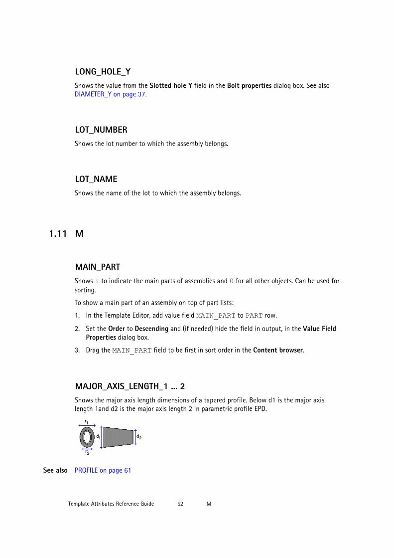
LONG_HOLE_YShows the value from the Slotted hole Y field in the Bolt properties dialog box. See alsoDIAMETER_Y on page 37.
LOT_NUMBERShows the lot number to which the assembly belongs.
LOT_NAMEShows the name of the lot to which the assembly belongs.
1.11 M
MAIN_PARTShows 1 to indicate the main parts of assemblies and 0 for all other objects. Can be used forsorting.
To show a main part of an assembly on top of part lists:
1. In the Template Editor, add value field MAIN_PART to PART row.
2. Set the Order to Descending and (if needed) hide the field in output, in the Value FieldProperties dialog box.
3. Drag the MAIN_PART field to be first in sort order in the Content browser.
MAJOR_AXIS_LENGTH_1 ... 2Shows the major axis length dimensions of a tapered profile. Below d1 is the major axislength 1and d2 is the major axis length 2 in parametric profile EPD.
PROFILE on page 61See also
Template Attributes Reference Guide 52 M

MARKIn drawing templates this field shows the last revision mark. In the DRAWING_REV lists italso shows the revision history. The revision mark of the revision entered in the RevisionHandling dialog box.
MATERIALShows the material name for parts. Shows the material of the assembly main part forassemblies. Shows the grade entered in the Bolt assembly catalog dialog box for bolts.
MATERIAL_TYPEShows the material type (STEEL, CONCRETE, etc) of assemblies or parts.
MESH_POSShows the position (prefix and running number) of a mesh.
MINOR_AXIS_LENGTH_1 ... 2Shows the minor axis length dimensions of a tapered profile. Below r1 is the minor axislength 1and r2 is the minor axis length 2 in parametric profile EPD.
PROFILE on page 61
MODELShows the name of the model.
See also
Template Attributes Reference Guide 53 M

MODEL_TOTALShows the number of similar objects in a model (i.e. those with the same position number).
MODULUS_OF_ELASTICITYShows the modulus of elasticity of a material from the material catalog.
MOMENT_OF_INERTIA_XShows the moment of inertia around the x-x reference axis of a cross section. Moment ofinertia is also known as the second moment of area.
PROFILE on page 61
MOMENT_OF_INERTIA_YShows the moment of inertia around the y-y reference axis of a cross section. Moment ofinertia is also known as the second moment of area.
PROFILE on page 61
moment1, moment2
Shows the values entered in the Moment, M box on the End codes tab in the user-definedattributes dialog box of the part. moment1 shows the value in the Start box and moment2in the End box.
MORTAR_VOLUMEShows the mortar volume used in surface treatment.
1.12 N
See also
See also
Template Attributes Reference Guide 54 N

NAMEThe name of the object. If the object does not have a name, it is searched from the next level.
Depending on the content type, shows:
Content type DescriptionASSEMBLY The assembly mainpart, project, phase or
drawing name.
BOLT Bolt name from the bolt catalog.
Nut, washer, phase, or project name.
CAST UNIT Project, mainpart, phase or drawing name
CONNECTION The connection name that appears in the titlebar of the corresponding connection propertiesdialog box.
Project name.
DRAWING The entire drawing name, including the drawingtype (A, W, C, G, M).
Project name.
HOLE Bolt, nut, washer, phase, or project name.
MESH The mesh name, or project name.
NUT The nut name, or bolt, washer, project or phasename.
PART Name entered in the part properties dialog boxfor parts.
Phase, assembly main part, drawing or projectname.
REBAR The reinforcing bar name.
Phase or project name.
STUD The stud name.
Project or phase name.
SURFACING Surface treatment name defined in theproduct_finishes.dat file
Project name.
WASHER The washer name from the bolt catalog.
Bolt, nut, project or phase name.
Template Attributes Reference Guide 55 N

NAME_BASEShows the drawing name.
NEUTRAL_AXIS_LOCATION_ELASTIC_XShows the location of elastic neutral axis.
PROFILE on page 61
NEUTRAL_AXIS_LOCATION_ELASTIC_YShows the location of elastic neutral axis.
PROFILE on page 61
NEUTRAL_AXIS_LOCATION_PLASTIC_XShows the location of plastic neutral axis.
PROFILE on page 61
NEUTRAL_AXIS_LOCATION_PLASTIC_YShows the location of plastic neutral axis.
PROFILE on page 61
NORMALIZED_WARPING_CONSTANTShows the warping constant of a profile.
PROFILE on page 61
See also
See also
See also
See also
See also
Template Attributes Reference Guide 56 N
NUMBER, NUMBER#1, NUMBER #2NUMBER shows the revision number in Rev. No box in the Revision Handling dialog box.
NUMBER#1 shows the total number of objects on a list. Shows the total number of partsand bolts for one assembly for list types ASSEMBLY, ASSEMBLY_BOLT, ASSEMBLY_PART and ASSEMBLY_ALL, if the object is part of an assembly on the list.
NUMBER#2 shows the project number as text.
NUMBER_IN_PHASE(X)
Returns the quantity of assemblies in phase X. The result is the same as the NUMBERtemplate attribute but by phase.
You can also use the template attribute PHASE and the function GetValue instead of anumber in the template attribute.
GetValue("NUMBER_IN_PHASE(GetValue("PHASE"))")
NUMBER_OF_TILE_TYPES
Returns the number of tiles in a tile pattern. For example, the Basketweave pattern is madeup of eight tiles, so the template attribute returns 8 for a tile surface treatment whosepattern type is Basketweave.
NUMBER_VISIBLE
When added in the reinforcing bar group mark, shows the number of visible reinforcing barsin the view. This is a context-specific template attribute.
1.13 O
OBJECTThe object field in the Project properties dialog box.
Example
See also
Template Attributes Reference Guide 57 O

OBJECT_DESCRIPTIONShows the object type and ID. Below examples:
• PART 780*380 Id: 227
• ASSEMBLY Id: 144
• MESH Id: 946
OBJECT_LOCKEDShows the status of the user-defined attribute Locked.
For more information on this attribute, see .
ORIGIN_X, ORIGIN_Y, ORIGIN_Z
It is possible to inquire the global coordinates of a connection's origin through templates. Thefields are named ORIGIN_X, ORIGIN_Y and ORIGIN_Z.
Template Attributes Reference Guide 58 O

OBJECT_TYPEThe type of object. The message files contain the translations of these strings (numbers 576 -587).
The object types are:
• POINT
• PART
• JOINT
• FITTING
• SCREW
• ANTI-MATERIAL
• CUT
• WELDING
• ASSEMBLY
• DRAWING
• PROJECT
• OBJECT
OWNERShows the object owner in format domain/user.
1.14 P
PAGEThe current page number.
PART_POSThe position number of parts. Shows a blank cell for all other objects.
Shows the mark of assembly main part for assemblies, parts, and bolts. For all other objectsthe field is blank.
Template Attributes Reference Guide 59 P

PART_PREFIXShows the part prefix, defined in the part properties dialog box.
For more information on numbering series, see .
PART_SERIAL_NUMBERShows the part number without the prefix and separator.
PART_START_NUMBER
Shows the part start number.
PCSShows the number of bars in a reinforcing bar group.
PHASEThe number of the phase to which the object belongs.
To show the phase name, use the PHASE.NAME field.
PLASTIC_MODULUS_XShows the plastic modulus of x-x reference axis of a cross section. Also known as the firstmoment of area.
PROFILE on page 61
PLASTIC_MODULUS_YShows the plastic modulus of y-y reference axis of a cross section. Also known as the firstmoment of area.
PROFILE on page 61
See also
See also
See also
Template Attributes Reference Guide 60 P
PLATE_DENSITYShows the material density of a plate (kg/m3).
PLATE_THICKNESSShows the thickness of a plate (mm).
PROFILE on page 61
PLOTFILEShows the name of the drawing plot file. Only for use in drawing tables and drawing reports.
POISSONS_RATIOShows the Poisson’s ratio (analysis property) of material.
POLAR_RADIUS_OF_GYRATIONShows the polar radius of gyration (analysis property) of a profile.
PROFILE on page 61
PRELIM_MARKShows the user-defined attribute Prelim mark.
For more information on preliminary marks, see .
See also
See also
See also
Template Attributes Reference Guide 61 P

PROFILEShows the part profile name, or the main part profile name in an assembly or cast unit. Youcan also show profile attributes in templates and reports:
In the Template editor, open the Select attribute dialog box and select PROFILE.* attributesfor the selected content type:
For example, MAINPART.PROFILE.HEIGHT with ASSEMBLY content type, shows the height ofthe main part profile in the assembly.
PROFILE_DENSITYShows the profile density of material (kg/m3).
Template Attributes Reference Guide 62 P

PROFILE_TYPEThe profile type of the part. The default types in Tekla Structures conform to DSTV-NCdocumentation. They are defined (message numbers 588 - 599) in the message fileby_number.ail in the folder ..\Tekla Structures\<version>\messages.The table below shows the relationship between messages, profiles in Tekla Structures, andthe DSTV-NC profile types defined in messages.
Tekla Structuresprofiles
Message number Shows DSTV-NCprofile type
I-profiles 588 I
L-profiles 589 L
U-profiles 591 U
Plates 592 B
Round tubes 593 RO
Round bars 594 RU
Rectangular tubes 595 M
CC-profiles 596 C
T-profiles 597 T
Polygon plates 598 B
Bent plates 599 B
Z-profiles and all theother types of profile
590 Z
PROFILE_WEIGHTThe weight of a part. For profiles Tekla Structures calculates the weight using the weight perunit length and weight/m values in the profile catalog. If the weight/m is not defined in theprofile catalog, this field works in the same way as WEIGHT_NET on page 81, but uses theplate density value (Property weight for plates) from the material catalog instead of profiledensity.
PROFILE_WEIGHT_NETThe net weight of a part. For profiles Tekla Structures calculates the weight using the lengthand weight/m values in the profile catalog. Line cuts do not affect the length value, which iscalculated using the fitted centerline. For all other objects this field works in the same wayas WEIGHT_NET on page 81.
Template Attributes Reference Guide 63 P

PROJECT_COMMENT
Shows the value entered in the Project Comment box in the user-defined attributes dialogbox of the project ( File --> Project Properties... --> User-defined Attributes... ).
PROJECT_USERFIELD_1 ... 8
Shows the value of the user-defined attribute of the project that you can define in the Userfield 1 , User field 2 and so on boxes on the Parameters tab in the user-defined attributesdialog box of the project ( File --> Project Properties... --> User-defined Attributes... ).
1.15 R
RADIUS
The Radius value of a curved beam.
RADIUS_OF_GYRATION_XShows the radius of gyration x (analysis property) of a profile.
PROFILE on page 61
RADIUS_OF_GYRATION_YShows the radius of gyration y (analysis property) of a profile.
PROFILE on page 61
REBAR_MESH_LEFT_OVERHANG_CROSS
Shows the extensions of the crossing bars over the outermost longitudinal bars on the left.
Creating a customized reinforcement mesh
See also
See also
See also
See also
See also
Template Attributes Reference Guide 64 R
REBAR_MESH_LEFT_OVERHANG_LONG
Shows the extensions of the longitudinal bars over the outermost crossing bars on the left.
Creating a customized reinforcement mesh
REBAR_MESH_RIGHT_OVERHANG_CROSS
Shows the extensions of the crossing bars over the outermost longitudinal bars on the left.
Creating a customized reinforcement mesh
REBAR_MESH_RIGHT_OVERHANG_LONG
Shows the extensions of the longitudinal bars over the outermost crossing bars on the right.
Creating a customized reinforcement mesh
REBAR_POSShows the position (prefix and the running number) of reinforcing bars.
REFERENCE_ASSEMBLY
Lists assembly level information on reference models in reports and templates.
The following attributes are bound to the content type incontentattributes_global.lst:
See also
See also
See also
Template Attributes Reference Guide 65 R

The following user-defined attributes are bound to the content type incontentattributes_userdefined.lst:
Template Attributes Reference Guide 66 R

REFERENCE_MODEL
Lists reference models in reports.
REFERENCE_MODEL_OBJECT
Lists reference models objects in reports.
See also
See also
See also
Template Attributes Reference Guide 67 R
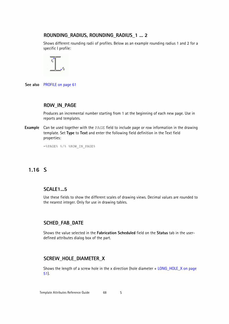
ROUNDING_RADIUS, ROUNDING_RADIUS_1 ... 2Shows different rounding radii of profiles. Below as an example rounding radius 1 and 2 for aspecific I profile:
PROFILE on page 61
ROW_IN_PAGEProduces an incremental number starting from 1 at the beginning of each new page. Use inreports and templates.
Can be used together with the PAGE field to include page or row information in the drawingtemplate. Set Type to Text and enter the following field definition in the Text fieldproperties:
=%PAGE% %/% %ROW_IN_PAGE%
1.16 S
SCALE1...5Use these fields to show the different scales of drawing views. Decimal values are rounded tothe nearest integer. Only for use in drawing tables.
SCHED_FAB_DATE
Shows the value selected in the Fabrication Scheduled field on the Status tab in the user-defined attributes dialog box of the part.
SCREW_HOLE_DIAMETER_X
Shows the length of a screw hole in the x direction (hole diameter + LONG_HOLE_X on page51).
See also
Example
Template Attributes Reference Guide 68 S

SCREW_HOLE_DIAMETER_Y
Shows the length of a screw hole in the y direction (hole diameter + LONG_HOLE_Y on page52).
SECTION_MODULUS_X, SECTION_MODULUS_YShows section modulus (analysis property) of a profile.
PROFILE on page 61
SHAPEShows the environment-specific bending type of a reinforcing bar.
SHAPE_INTERNAL
Shows the internal bending type of Tekla Structures for a reinforcing bar, for example, 2_1.
SHEAR_CENTER_LOCATIONShows the shear center location (analysis property) of a profile.
PROFILE on page 61
shear1, shear2
Shows the values entered in the Shear, V box on the End codes tab in the user-definedattributes dialog box of the part. shear1 shows the value in the Start box and shear2 inthe End box.
SHOP_ISSUE
Shows the value selected in the Plans Actual field on the Status tab in the user-definedattributes dialog box of the part or in the assembly properties dialog box.
See also
See also
See also
Template Attributes Reference Guide 69 S

SHOPSTATUS
Shows the value selected in the Fabrication Status list on the Status tab in the user-definedattributes dialog box of the part or in the assembly properties dialog box.
SIMILAR_TO_MAIN_PARTReturns 1 if the position number of the given part is the same as the position number of themain part in the assembly.
To show a main part of an assembly on top of part lists:
1. In the Template Editor, add value field SIMILAR_TO_MAIN_PART to PART row.
2. Set the Order to Descending and (if needed) hide the field in output, in the Value FieldProperties dialog box.
3. Drag the SIMILAR_TO_MAIN_PART field to be first in sort order in the Content browser.
SITE_WORKSHOPFor bolts this field shows the assembly type information in a string (Site or Shop). Themessage files (466 and 467) contain translations of these strings.
For studs this field shows the assembly type information in a string (Site or Shop).
SIZEShows the size of the drawing (e.g. 210x297). Only for use in drawing templates and drawingreports.
SORT_OF_E_x_Cw_PER_G_x_JShows sqrt(ECw/GJ) analysis property of a profile.
PROFILE on page 61See also
Template Attributes Reference Guide 70 S
SUPPLEMENT_PART_WEIGHTShows the weight of supplementary parts. SUPPLEMENT_PART_WEIGHT = the weight of thewhole assembly less the weight of the main part.
See also WEIGHT on page 80.
START_XShows the coordinates of the creation points of parts.
START_YSee START_X on page 71.
START_ZSee START_X on page 71.
STATICAL_MOMENT_QfShows the statical moment of the flange.
PROFILE on page 61
STATICAL_MOMENT_QwShows the statical moment of the web.
PROFILE on page 61
STIFFENER_DIMENSIONShows the stiffener dimension of a profile.
STIFFENER_DIMENSION_1 ... 3 on page 72
PROFILE on page 61
See also
See also
See also
Template Attributes Reference Guide 71 S
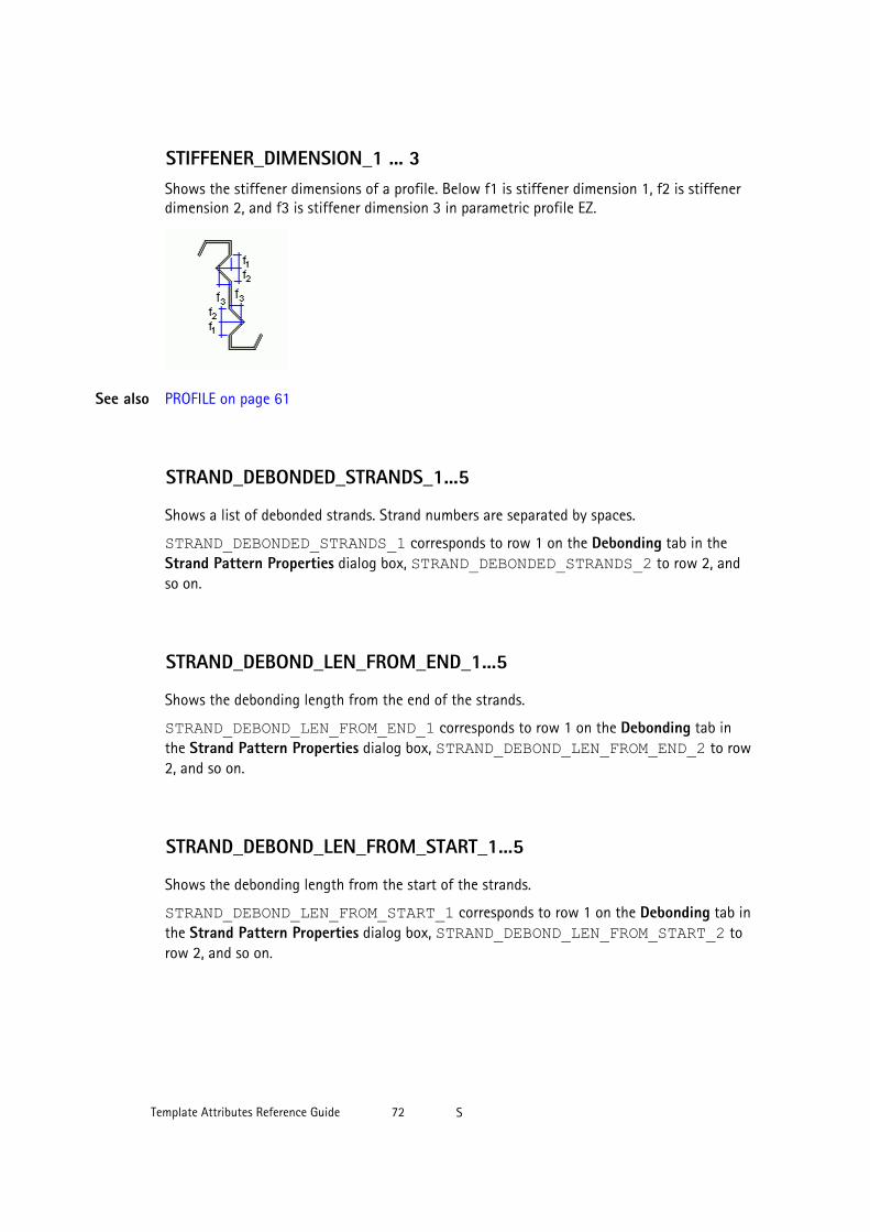
STIFFENER_DIMENSION_1 ... 3Shows the stiffener dimensions of a profile. Below f1 is stiffener dimension 1, f2 is stiffenerdimension 2, and f3 is stiffener dimension 3 in parametric profile EZ.
PROFILE on page 61
STRAND_DEBONDED_STRANDS_1...5
Shows a list of debonded strands. Strand numbers are separated by spaces.
STRAND_DEBONDED_STRANDS_1 corresponds to row 1 on the Debonding tab in theStrand Pattern Properties dialog box, STRAND_DEBONDED_STRANDS_2 to row 2, andso on.
STRAND_DEBOND_LEN_FROM_END_1...5
Shows the debonding length from the end of the strands.
STRAND_DEBOND_LEN_FROM_END_1 corresponds to row 1 on the Debonding tab inthe Strand Pattern Properties dialog box, STRAND_DEBOND_LEN_FROM_END_2 to row2, and so on.
STRAND_DEBOND_LEN_FROM_START_1...5
Shows the debonding length from the start of the strands.
STRAND_DEBOND_LEN_FROM_START_1 corresponds to row 1 on the Debonding tab inthe Strand Pattern Properties dialog box, STRAND_DEBOND_LEN_FROM_START_2 torow 2, and so on.
See also
Template Attributes Reference Guide 72 S

STRAND_DEBOND_LEN_MIDDLE_TO_END_1...5
Shows the debonding length from the middle to the end of the strands.
STRAND_DEBOND_LEN_MIDDLE_TO_END_1 corresponds to row 1 on the Debondingtab in the Strand Pattern Properties dialog box, STRAND_DEBOND_LEN_MIDDLE_TO_END_2 to row 2, and so on.
STRAND_DEBOND_LEN_MIDDLE_TO_START_1...5
Shows the debonding length from the middle to the start of the strands.
STRAND_DEBOND_LEN_MIDDLE_TO_START_1 corresponds to row 1 on theDebonding tab in the Strand Pattern Properties dialog box, STRAND_DEBOND_LEN_MIDDLE_TO_START_2 to row 2, and so on.
STRAND_N_PATTERNShows the number of different cross-sections in a strand pattern.
STRAND_N_STRANDShows the number of strands.
STRAND_POSShows the position (prefix and running number) of a strand.
STRAND_PULL_FORCEShows the pull force of a strand.
STRAND_UNBONDEDShows the sequence numbers of debonded strands, separated by spaces or commas.
Template Attributes Reference Guide 73 S
SUBTYPEShows the subtype of a profile.
PROFILE on page 61
SURFACING_NAMEShows the name of a surface treatment, for example, Tile surface 1.
Surface treatment codes and names are defined in the product_finishes.dat file.
CODE on page 30
1.17 T
TANGENT_OF_PRINCIPAL_AXIS_ANGLEShows the tangent of principal axis angle (analysis property) of a profile.
PROFILE on page 61
TEXT1...3In drawing templates this field shows the text for the last revision. In DRAWING_REV lists italso shows the revision history.
THERMAL_DILATATIONShows the thermal dilatation coefficient of material.
THICKNESS
Shows the thickness of a tile in a tile pattern.
See also
See also
See also
See also
Template Attributes Reference Guide 74 T

THREAD_IN_MATERIALShows 1 if the thread of the screw can be inside the material to be connected and 0 if not.
TILE_NUMBERShows the number of tiles used in surface treatment (approximate value).
TILE_VOLUMEShows the volume of tiles used in surface treatment, without the mortar volume. See alsoMORTAR_VOLUME on page 54.
TIMEShows the current time (hh:mm:ss).
TITLEShows the user-defined drawing name. Can also be used for parts and assemblies. Forexample, you could create a report of assemblies listing which assembly drawings had beencreated.
TITLE1...3In reports this field shows the user-defined titles entered in the Report dialog box. Indrawing templates this field shows the drawing attributes.
TOP_LEVEL
Shows the top level of a single part, cast unit, assembly, part of a connection or a pourobject.
Top level takes the unit and accuracy from MarkDimensionFormat.dim.
You can use this attribute as a user-defined attribute also in part marks and associativenotes.
Template Attributes Reference Guide 75 T

This attribute returns the value as text, so you cannot use formulae with thisattribute. Use TOP_LEVEL_UNFORMATTED on page 76 instead.
TOP_LEVEL_GLOBAL
Shows the top level of a single part, cast unit, assembly, part of a connection or a pour objectby global axis. TOP_LEVEL_GLOBAL takes the unit and accuracy fromMarkDimensionFormat.dim.
You can use this attribute as a user-defined attribute in part marks and associative notes,and also in reports and templates.
TOP_LEVEL_GLOBAL_UNFORMATTED
Shows the top level of a single part, cast unit, assembly, part of a connection or a pourobject. TOP_LEVEL_GLOBAL_UNFORMATTED returns the top levels as a length in mm soyou can format them and include them into formulas in templates. This attribute gives levelinformation by the global axis.
You can use this attribute as a user-defined attribute also in part marks and associativenotes.
TOP_LEVEL_UNFORMATTED
Shows the top level of a single part, cast unit, assembly, part of a connection or a pourobject. TOP_LEVEL_UNFORMATTED returns the top levels as a length in mm so you canformat them and include them into formulas in templates.
You can use this attribute as a user-defined attribute also in part marks and associativenotes.
Unlike the TOP_LEVEL attribute, the TOP_LEVEL_UNFORMATTED attributecannot be formatted through the MarkDimensionFormat.dim file.
Template Attributes Reference Guide 76 T

TORSIONAL_CONSTANTShows the torsional constant (analysis property) of a profile.
PROFILE on page 61
TYPEShows the object type or standard:
Content type DescriptionBOLT Shows the bolts standard as it appears in the
Bolt assembly catalog dialog box (forexample, 7968). For all other objects the fieldis blank.
DRAWING Shows the drawing type: A, W, C, G or M.
MESH Shows the mesh standard.
NUT Shows the nut standard.
SURFACING Surface treatment type in the SurfaceTreatment Properties dialog box.
WASHER Shows the standard of the washer.
TYPE1For bolts this field shows the bolt type as the type of each possible bolt part that appears inthe Bolt assembly catalog dialog box (e.g. 7968/2041/2041/2041/2067/2067). For objectsother than bolts the field is blank.
TYPE2For bolts this field shows the bolt type as the numbers of existing bolt parts (e.g. 10021). Forobjects other than bolts the field is blank.
TYPE3The same as BOLT_TYPE2, but shows X for existing and o for nonexistent bolt parts (forexample, XooXX). For objects other than bolts the field shows a blank.
See also
Template Attributes Reference Guide 77 T

TYPE4The same as BOLT_TYPE1 but only the existing components are shown in the string.
1.18 U
USER_PHASE
Shows the value entered in the User Phase box on the Parameters tab in the user-definedattributes dialog box of the part.
USERFIELD_1 ... _8Shows the value of the user-defined attribute User field 1, User field 2 etc.
For more information on the user-defined attributes in templates and reports, see .
For more information on user-defined attributes, see and .
1.19 V
VOLUMEShows the object volume, for example, the volume of an assembly or of a cast unit. Takesholes and cuts into account.
VOLUME_GROSSShows the object gross volume. Does not take into account holes and cuts.
VOLUME_NETShows the object volume taking into account holes and cuts.
See also
Template Attributes Reference Guide 78 U
VOLUME_NET_ONLY_CONCRETE_PARTS
Shows the volume by the solid of concrete parts in the cast unit. If a part uses a profilewhere cross section area is defined manually, it is ignored in calculation ( cf. VOLUME_ONLY_CONCRETE_PARTS)
VOLUME_ONLY_CONCRETE_PARTS
This attribute gets cast unit volume values only for concrete parts.
1.20 W
WARPING_CONSTANTShows the warping constant (analysis property) of a profile.
PROFILE on page 61
WARPING_STATICAL_MOMENTShows the warping statical moment (analysis property) of a profile.
PROFILE on page 61
WEB_HEIGHTSee WEB_WIDTH on page 80.
WEB_LENGTHThe gross length of the web of an I profile. Use to show welded profiles as plates.
See also
See also
Template Attributes Reference Guide 79 W

WEB_THICKNESSThe thickness of the web of an I profile. Use to show welded profiles as plates.
PROFILE on page 61
WEB_THICKNESS_1, WEB_THICKNESS_2The additional thickness values of the web of a profile.
PROFILE on page 61
WEB_WIDTHThe width of the web of an I profile. Use to show welded profiles as plates.
WEIGHTShows the weight of the object. The calculation formula depends on the object type:
• For parts with cross-sections defined in the profile catalog, the weight is calculated fromthe cross section area in the profile catalog (on the list of Properties on the Analysistab), length (LENGTH) and density of material (property weight for profiles in thematerial catalog). The result is the same as calculating WEIGHT_GROSS.
• For other profiles with no cross sections defined (typically parametric profiles), shows thenet weight calculated using the profile volume and density of material. Fittings, cuts,weld preparations, and part adds affect volume calculation.
• For assemblies, shows the sum of the part weights for each assembly.
• For bolts, shows the weight of the bolt part in the corresponding content type rows:
• BOLT: shows the weight of the bolt.
• NUT: shows the weight of the nut.
• WASHER: shows the weight of the washer.
See also
See also
Template Attributes Reference Guide 80 W
WEIGHT_GROSSShows the gross weight, which is the total weight of material needed to fabricate the part.The calculation formula depends on the part:
• If the part has cross-sections defined in the profile catalog, the weight is calculated frompart length (LENGTH), the cross section area in the profile catalog, and the density ofmaterial.
• If the part is a folded or contour plate without a cross section area, the weight iscalculated from plate overall height, overall length and density of material (propertyweight for plates in the material catalog).
• For other profiles without cross sections (typically parametric profiles), the gross weightis calculated the same way as the WEIGHT_NET, but cuts are not taken into accountand the plate density value is used instead of profile density.
• For assemblies, shows the combined gross weight of parts included in an assembly. Forbolts it shows the bolt weight.
WEIGHT_MShows the property weight of a profile (defined in the material catalog). For parametricprofiles, shows the weight of the profile divided by the length. For standard profiles, showsthe Weight per unit length from the Analysis properties in the profile catalog.
WEIGHT_MAXShows the maximum weight of a single reinforcing bar or strand in a reinforcing bar group.
WEIGHT_MINShows the minimum weight of a single reinforcing bar or strand in a reinforcing bar group.
WEIGHT_NETShows the weight of the fabricated part, assembly or cast unit. The calculation formuladepends on the object:
• For parts, returns the net weight, which is the actual weight of the fabricated part.Rounding of the profile corners are not taken into account.
• For bolts, returns the bolt weight, and for other objects a zero.
• For assemblies, returns the sum of part weights.
Template Attributes Reference Guide 81 W

The calculation is based on part volume and density of material. The density value used in thecalculation depends on the profile cross-sections:
• If cross-sections are defined in the profile catalog, density is the Property weight ofprofiles in the material catalog.
• If there are no cross-sections, density is the Property weight of plates in the materialcatalog.
For parts, the net weight is not the actual weight of the fabricated parts. The profile crosssection is calculated using straight angles, so the roundings in the corners are not takeninto account (unless you are using the advanced option XS_SOLID_USE_HIGHER_ACCURACY). This causes significant difference between thecalculated and the actual weight especially when big cross sections are used.
WEIGHT_NET_ONLY_CONCRETE_PARTS
Shows the weight of a cast unit. It calculates the weight by the solid of the concrete parts inthe cast unit. If a part uses a profile where cross section area is defined manually, it isignored in calculation ( cf. WEIGHT_ONLY_CONCRETE_PARTS).
WEIGHT_ONLY_CONCRETE_PARTS
This attribute gets the cast unit weight only for concrete parts only.
WEIGHT_PER_UNIT_LENGTHShows the weight per unit length (analysis property) of a profile.
PROFILE on page 61See also
Template Attributes Reference Guide 82 W

WEIGHT_TOTALShows the total weight of all reinforcing bars or of all strands in a reinforcing bar group.
WELD_ACTUAL_LENGTH1, WELD_ACTUAL_LENGTH2
Shows the actual weld length in the model, or the sum of actual weld lengths, for weldsabove and below line.
The actual weld length is the distance between the weld seam start point and end pointalong the weld seam.
WELD_LENGTH1 ... 2 on page 85
WELD_ANGLE1, WELD_ANGLE2Shows weld angle for welds above and below line.
WELD_ASSEMBLYTYPEShows the assembly type of a weld (Site or Shop). Only use in welding lists.
WELD_DEFAULTShows the default weld size according to the drawing attributes. Only use in drawing tables.
WELD_CROSSSECTION_AREA1, WELD_CROSSSECTION_AREA2
Shows the theoretical cross section area for welds above and below line. For unsupportedweld types, shows 0.00.
See also
Template Attributes Reference Guide 83 W

WELD_EDGE_AROUND
Returns the value selected in the Edge/Around list in the Weld Properties dialog box: Edgeif only one edge of a face is welded and Around if the entire perimeter is welded.
WELD_EFFECTIVE_THROAT, WELD_EFFECTIVE_THROAT2
Returns the value entered in the Effective throat box in the Weld Properties dialog box. WELD_EFFECTIVE_THROAT shows the value entered in the Above line section, and WELD_EFFECTIVE_THROAT2 in the Below line section.
WELD_ELECTRODE_CLASSIFICATION
Shows the weld electrode classification, selected in the Electrode classification list in theWeld properties dialog box.
WELD_ELECTRODE_COEFFICIENT
Shows the value entered in the Electrode coefficient box in the Weld properties dialog box.
WELD_ELECTRODE_STRENGTH
Shows the value entered in the Electrode strength box in the Weld properties dialog box.
WELD_ERRORLISTShows error codes for a weld if there are issues related to the weld.
The error codes are:
Error code DescriptionE1 Weld is not in the correct location.
E2 Welded parts are not touching each other.
See also
See also
See also
See also
See also
Template Attributes Reference Guide 84 W

Error code DescriptionE3 Weld is not on the edge of a part.
E4 Weld has a cross section type that is not supported.
E5 Weld properties are incorrect.
E6 There are issues related to the weld preparation of parts.
WELD_FATHER_CODEShows the connection running number of the connection where the weld is located. The fieldis blank if the weld is not next to a connection. Use only in welding lists.
WELD_FATHER_NUMBERShows the connection number of the connection where the weld is located. The field is blankif the weld is not next to a connection. Use only in welding lists.
WELD_FILLTYPE1, WELD_FILLTYPE2Shows the weld contour (None, Flush, Convex, Concave) for welds above and below line.
WELD_FINISH1, WELD_FINISH2Shows the weld finish for welds above and below line.
WELD_INCREMENT_AMOUNT1, WELD_INCREMENT_AMOUNT2
Shows the amount of increments for intermittent welds above and below line.
WELD_INTERMITTENT_TYPE
Shows the shape of a weld (Continuous, Chain intermittent, or Staggered intermittent).
See also
See also
Template Attributes Reference Guide 85 W

WELD_LENGTH1 ... 2
Shows the weld length value entered in the Length box in the Weld Properties dialog box. WELD_LENGTH1 shows the length of the weld above the line and WELD_LENGTH2 belowthe line.
WELD_ACTUAL_LENGTH1, WELD_ACTUAL_LENGTH2 on page 83
WELD_NDT_INSPECTION
Shows the non-destructive testing and inspection level of a weld, selected in the NDTinspection level list in the Weld properties dialog box.
WELD_NUMBER
Shows the weld number.
WELD_PERIOD1 ... 2
Returns the value entered in the Pitch box in the Weld Properties dialog box. WELD_PERIOD1 returns the value entered in the Above line section, and WELD_PERIOD2 in the Below line section.
WELD_POSITION
Returns the weld position, selected in the Position list in the Weld Properties dialog box.
WELD_POSITION_X
Shows the position of the weld in the x axis.
See also
See also
See also
See also
See also
See also
Template Attributes Reference Guide 86 W

WELD_POSITION_Y
Shows the position of the weld in the y axis.
WELD_POSITION_Z
Shows the position of the weld in the z axis.
WELD_PROCESS_TYPE
Shows the welding process type of a weld, selected in the Welding process type list in theWeld properties dialog box.
WELD_ROOT_FACE_THICKNESS, WELD_ROOT_FACE_THICKNESS2Shows the root face thickness of a weld above or below line and is used only in welding lists.
WELD_ROOT_OPENING, WELD_ROOT_OPENING2
Shows the root opening (space between the welded parts) for welds above and below line.
WELD_SIZE1, WELD_SIZE2Shows weld size for welds above and below line.
WELD_SIZE_PREFIX_ABOVE
Returns the weld size prefix, entered in the Prefix box in the Above line section in the WeldProperties dialog box.
See also
See also
See also
See also
See also
Template Attributes Reference Guide 87 W

WELD_SIZE_PREFIX_BELOW
Returns the weld size prefix, entered in the Prefix box in the Below line section in the WeldProperties dialog box.
WELD_TEXTShows the reference text of a weld.
WELD_TYPE1, WELD_TYPE2Shows weld type for above and below line. See the .
WELD_VOLUME
Shows the volume of a solid weld object. If the solid weld object fails, shows 0.00. Forunsupported weld types, shows 0.00.
WIDTHThe width of a part or assembly.
For drawings, shows the width of the drawing.
PROFILE on page 61
WIDTH_1, WIDTH_2Shows special width values of some profiles. Below parametric profile rectangular hollowsection with subtype h1*b1-h2*b2*t, where b1 is width 1 and b2 is width 2.
PROFILE on page 61
See also
See also
See also
Template Attributes Reference Guide 88 W

1.21 X
xs_shorten
Shows the value entered in the Shorten box on the Parameters tab in the user-definedattributes dialog box of the part.
Template Attributes Reference Guide 89 X

2 Disclaimer
© 2015 Tekla Corporation and its licensors. All rights reserved.
This Software Manual has been developed for use with the referenced Software. Use of theSoftware, and use of this Software Manual are governed by a License Agreement. Amongother provisions, the License Agreement sets certain warranties for the Software and thisManual, disclaims other warranties, limits recoverable damages, defines permitted uses of theSoftware, and determines whether you are an authorized user of the Software. Allinformation set forth in this manual is provided with the warranty set forth in the LicenseAgreement. Please refer to the License Agreement for important obligations and applicablelimitations and restrictions on your rights. Tekla does not guarantee that the text is free oftechnical inaccuracies or typographical errors. Tekla reserves the right to make changes andadditions to this manual due to changes in the software or otherwise.
In addition, this Software Manual is protected by copyright law and by international treaties.Unauthorized reproduction, display, modification, or distribution of this Manual, or anyportion of it, may result in severe civil and criminal penalties, and will be prosecuted to thefull extent permitted by law.
Tekla, Tekla Structures, Tekla BIMsight, BIMsight, Tedds, Solve, Fastrak and Orion are eitherregistered trademarks or trademarks of Tekla Corporation in the European Union, the UnitedStates, and/or other countries. More about Tekla trademarks: http://www.tekla.com/tekla-trademarks. Trimble is a registered trademark or trademark of Trimble Navigation Limited inthe European Union, in the United States and/or other countries. More about Trimbletrademarks: http://www.trimble.com/trademarks.aspx. Other product and company namesmentioned in this Manual are or may be trademarks of their respective owners. By referringto a third-party product or brand, Tekla does not intend to suggest an affiliation with orendorsement by such third party and disclaims any such affiliation or endorsement, exceptwhere otherwise expressly stated.
Portions of this software:
D-Cubed 2D DCM © 2010 Siemens Industry Software Limited. All rights reserved.
EPM toolkit © 1995-2004 EPM Technology a.s., Oslo, Norway. All rights reserved.
Open CASCADE Technology © 2001-2014 Open CASCADE SA. All rights reserved.
FLY SDK - CAD SDK © 2012 VisualIntegrity™. All rights reserved.
Teigha © 2003-2014 Open Design Alliance. All rights reserved.
PolyBoolean C++ Library © 2001-2012 Complex A5 Co. Ltd. All rights reserved.
Disclaimer 90 X

FlexNet Copyright © 2014 Flexera Software LLC. All Rights Reserved.
This product contains proprietary and confidential technology, information and creativeworks owned by Flexera Software LLC and its licensors, if any. Any use, copying, publication,distribution, display, modification, or transmission of such technology in whole or in part inany form or by any means without the prior express written permission of Flexera SoftwareLLC is strictly prohibited. Except where expressly provided by Flexera Software LLC in writing,possession of this technology shall not be construed to confer any license or rights under anyFlexera Software LLC intellectual property rights, whether by estoppel, implication, orotherwise.
To see the third party licenses, go to Tekla Structures, click Help --> About and click theThird party licenses button.
The elements of the software described in this Manual are protected by several patents andpossibly pending patent applications in the European Union and/or other countries. For moreinformation go to page http://www.tekla.com/tekla-patents.
Disclaimer 91 X

Disclaimer 92 X

Index
Aassembly bottom level
global............................................................................ 16assembly top level
global............................................................................ 20
Bbottom level
global............................................................................ 23
Cconnections
origin.............................................................................58
Iinternal bending type.......................................................69internal shape.................................................................... 69
Llevel attributes.............................................................23,76
MMarkDimensionFormat.dim.......................... 16,23,75,76
Nnumber of visible reinforcing bars............................... 57
Rreinforcing bar groups
number of visible reinforcing bars........................57
Ttable attributes.................................................................. 11template attributes...........................................................11top level......................................................................... 75,76
global............................................................................ 76
93

94