technical specification · 2018-08-09 · ericsson, intel corp., nokia, qualcomm technologies inc.,...
TRANSCRIPT

TS 5G.331 v1.0 (2016-08) Technical Specification
KT PyeongChang 5G Special Interest Group (KT 5G-SIG);
KT 5th Generation Radio Access;
Radio Resource Control (RRC);
Protocol specification
(Release 1)
Ericsson, Intel Corp., Nokia, Qualcomm Technologies Inc., Samsung Electronics & KT
Disclaimer: This document provides information related to 5G technology. All information provided herein is subject to change without notice. The members of the KT PyeongChang 5G Special Interest Group (“KT 5G-SIG”) disclaim and make no guaranty or warranty, express or implied, as to the accuracy or completeness of any information contained or referenced herein. THE KT 5G-SIG AND ITS MEMBERS DISCLAIM ANY IMPLIED WARRANTY OF MERCHANTABILITY, NON-INFRINGEMENT, OR FITNESS FOR ANY PARTICULAR PURPOSE, AND ALL INFORMATION IS PROVIDED ON AN “AS-IS” BASIS. No licenses under any intellectual property of any kind are provided by any person (whether a member of the KT 5G-SIG or not) that may be necessary to access or utilize any of the information contained herein, including, but not limited to, any source materials referenced herein, and any patents required to implement or develop any technology described herein. It shall be the responsibility of anyone attempting to use the information contained or referenced herein to obtain any such licenses, if necessary. The KT 5G-SIG and its members disclaim liability for any damages or losses of any nature whatsoever whether direct, indirect, incidental, special or consequential resulting from the use of or reliance on any information contained or referenced herein.
© 2016 KT corp. All rights reserved
KT 5G-SIG
TS 5G.331 v1.0 (2016-08) 2
Document History
Version Date Change
0.1.0 2016-04-06 First Draft Version
0.1.1 2016-05-08 Updated version
0.1.2 2016-05-20 Updated after 1st Teleconference
0.1.3 2016-06-01 Updated after 2nd
Teleconference
0.1.4 2016-06-14 Include IWK part
0.1.5 2016-06-30 Add RRC operation for SA mode
Apply CRs on beam management, Security, UE Capability, and IEs
0.1.6 2016-08-05 Apply CRs on RRC IEs, Security, Measurement
0.1.7 2016-08-23 Apply CRs on details for SA-related operation and ASN.1
1.0.0 2016-08-30 1st Release Version
KT 5G-SIG
TS 5G.331 v1.0 (2016-08) 3
Contents
Foreword............................................................................................................................................................. 8
1 Scope ........................................................................................................................................................ 9
2 References ................................................................................................................................................ 9
3 Definitions, symbols and abbreviations ................................................................................................... 9 3.1 Definitions ......................................................................................................................................................... 9 3.2 Abbreviations ................................................................................................................................................... 10
4 General ................................................................................................................................................... 10 4.1 Introduction...................................................................................................................................................... 10 4.2 Architecture ..................................................................................................................................................... 10 4.2.1 UE states and state transitions .................................................................................................................... 10 4.2.2 Signalling radio bearers .............................................................................................................................. 11 4.3 Services ............................................................................................................................................................ 12 4.3.1 Services provided to upper layers .............................................................................................................. 12 4.3.2 Services expected from lower layers .......................................................................................................... 12 4.4 Functions ......................................................................................................................................................... 12
5 Procedures .............................................................................................................................................. 13 5.1 General ............................................................................................................................................................. 13 5.1.1 Introduction ................................................................................................................................................ 13 5.1.2 General Requirements ................................................................................................................................ 13 5.2 System Information.......................................................................................................................................... 14 5.2.1 Introduction ................................................................................................................................................ 14 5.2.1.1 General ................................................................................................................................................. 14 5.2.1.2 Scheduling ............................................................................................................................................ 14 5.2.1.3 System information validity and notification of changes ..................................................................... 14 5.2.2 System information acquisition .................................................................................................................. 14 5.2.2.1 General ................................................................................................................................................. 14 5.2.2.2 Initiation ............................................................................................................................................... 15 5.2.2.3 System information required by the UE ............................................................................................... 15 5.2.2.4 System information acquisition by the UE ........................................................................................... 15 5.2.2.5 Essential system information missing................................................................................................... 15 5.2.2.6 Actions upon reception of the MasterInformationBlock message ........................................................ 16 5.2.2.7 Actions upon reception of the XSystemInformationBlock message .................................................... 16 5.3 Connection Control .......................................................................................................................................... 16 5.3.1 Introduction ................................................................................................................................................ 16 5.3.1.1 RRC connection control in standalone mode ....................................................................................... 16 5.3.1.1a RRC connection control in non-standalone mode ................................................................................ 16 5.3.1.2 Security in standalone mode ................................................................................................................. 17 5.3.1.2a Security in non-standalone mode.......................................................................................................... 18 5.3.1.3 Connected mode mobility ..................................................................................................................... 18 5.3.2 Void ............................................................................................................................................................ 19 5.3.3 RRC connection establishment in standalone operation ............................................................................ 19 5.3.3.1 General ................................................................................................................................................. 19 5.3.3.2 Initiation ............................................................................................................................................... 20 5.3.3.3 Actions related to transmission of RRCConnectionRequest message ................................................... 20 5.3.3.4 Reception of the RRCConnectionSetup by the UE ............................................................................... 20 5.3.3.5 Cell selection while T300, T302 is running .......................................................................................... 21 5.3.3.6 T300 expiry .......................................................................................................................................... 21 5.3.3.7 T302 expiry or stop .............................................................................................................................. 21 5.3.3.8 Reception of the RRCConnectionReject by the UE .............................................................................. 21 5.3.3a 5G RRC connection establishment via E-UTRAN .................................................................................... 22 5.3.3a.1 General ................................................................................................................................................. 22 5.3.3a.2 Initiation ............................................................................................................................................... 22 5.3.4 Initial Security Activation .......................................................................................................................... 22 5.3.4.1 General ................................................................................................................................................. 22 5.3.4.2 Initiation ............................................................................................................................................... 23

KT 5G-SIG
TS 5G.331 v1.0 (2016-08) 4
5.3.4.3 Reception of the SecurityModeCommand by the UE ........................................................................... 23 5.3.5 RRC connection reconfiguration ................................................................................................................ 24 5.3.5.1 General ................................................................................................................................................. 24 5.3.5.2 Initiation ............................................................................................................................................... 24 5.3.5.3 Reception of an RRCConnectionReconfiguration not including the mobilityControlInfo by the
UE ......................................................................................................................................................... 24 5.3.5.4 Reception of an RRCConnectionReconfiguration including the mobilityControlInfo by the UE
(handover) ............................................................................................................................................ 25 5.3.5.5 Reconfiguration failure ......................................................................................................................... 27 5.3.5.6 T304 expiry (handover failure) ............................................................................................................. 28 5.3.5.8 Radio Configuration involving full configuration option ..................................................................... 28 5.3.5.9 Radio Configuration involving configuration release option ............................................................... 29 5.3.6 Counter Check ............................................................................................................................................ 29 5.3.6.1 General ................................................................................................................................................. 29 5.3.6.2 Initiation ............................................................................................................................................... 29 5.3.6.3 Reception of the CounterCheck message by the UE ............................................................................ 29 5.3.7 RRC connection re-establishment .............................................................................................................. 30 5.3.7.1 General ................................................................................................................................................. 30 5.3.7.2 Initiation ............................................................................................................................................... 31 5.3.7.3 Actions following cell selection while T311 is running ....................................................................... 31 5.3.7.4 Actions related to transmission of RRCConnectionReestablishmentRequest message......................... 31 5.3.7.5 Reception of the RRCConnectionReestablishment by the UE .............................................................. 32 5.3.7.6 T311 expiry .......................................................................................................................................... 33 5.3.7.7 T301 expiry or selected cell no longer suitable .................................................................................... 33 5.3.7.8 Reception of RRCConnectionReestablishmentReject by the UE .......................................................... 33 5.3.8 RRC connection release ............................................................................................................................. 33 5.3.8.1 General ................................................................................................................................................. 33 5.3.8.2 Initiation ............................................................................................................................................... 33 5.3.8.3 Reception of the RRCConnectionRelease by the UE ........................................................................... 34 5.3.9 Void ............................................................................................................................................................ 34 5.3.10 Radio resource configuration ..................................................................................................................... 34 5.3.10.0 General ................................................................................................................................................. 34 5.3.10.1 Void ...................................................................................................................................................... 34 5.3.10.2 DRB release .......................................................................................................................................... 35 5.3.10.3 DRB addition/ modification ................................................................................................................. 35 5.3.10.3a SCell release ......................................................................................................................................... 36 5.3.10.3b SCell addition/ modification ................................................................................................................. 36 5.3.10.4 MAC main reconfiguration .................................................................................................................. 36 5.3.10.5 Void ...................................................................................................................................................... 36 5.3.10.6 Physical channel reconfiguration .......................................................................................................... 36 5.3.10.7 Radio Link Failure Timers and Constants reconfiguration ................................................................... 36 5.3.10.8 Random access channel reconfiguration............................................................................................... 37 5.3.11 Radio link failure related actions ................................................................................................................ 37 5.3.11.1 Detection of physical layer problems in RRC_CONNECTED ............................................................ 37 5.3.11.2 Recovery of physical layer problems ................................................................................................... 37 5.3.11.3 Detection of radio link failure............................................................................................................... 37 5.3.12 UE actions upon leaving 5G RRC_CONNECTED .................................................................................... 38 5.4 Void ................................................................................................................................................................. 38 5.5 Measurements .................................................................................................................................................. 38 5.5.1 Introduction ................................................................................................................................................ 38 5.5.2 Measurement configuration ........................................................................................................................ 39 5.5.2.1 General ................................................................................................................................................. 39 5.5.2.2 Measurement identity removal ............................................................................................................. 40 5.4.2.2a Measurement identity autonomous removal ......................................................................................... 40 5.5.2.3 Measurement identity addition/ modification ....................................................................................... 40 5.5.2.4 Measurement object removal ................................................................................................................ 41 5.5.2.5 Measurement object addition/ modification ......................................................................................... 41 5.5.2.6 Reporting configuration removal .......................................................................................................... 42 5.5.2.7 Reporting configuration addition/ modification ................................................................................... 42 5.5.2.8 Quantity configuration .......................................................................................................................... 42 5.5.3 Performing measurements .......................................................................................................................... 43 5.5.3.1 General ................................................................................................................................................. 43

KT 5G-SIG
TS 5G.331 v1.0 (2016-08) 5
5.5.3.2 Layer 3 filtering .................................................................................................................................... 43 5.5.4 Measurement report triggering ................................................................................................................... 44 5.5.4.1 General ................................................................................................................................................. 44 5.5.4.2 Event A1 (Serving 5G cell becomes better than threshold) .................................................................. 45 5.5.4.3 Event A2 (Serving 5G cell becomes worse than threshold) ................................................................. 45 5.5.4.4 Event A3 (Neighbour 5G cell becomes offset better than serving 5G cell) .......................................... 46 5.5.4.5 Event A4 Neighbour 5G cell becomes better than threshold. ............................................................... 47 5.5.4.6 Event A5 (PCell becomes worse than threshold1 and neighbour becomes better than threshold2)
(for standalone mode) ........................................................................................................................... 47 5.5.5 Measurement reporting .............................................................................................................................. 48 5.5.5.1 Measurement reporting triggered by measurement configuration ........................................................ 48 5.5.5.2 Measurement reporting triggered by RLF ............................................................................................ 49 5.5.6 Measurement related actions ...................................................................................................................... 50 5.5.6.1 Actions upon handover and re-establishment ....................................................................................... 50 5.5.6.2 Initiation of UE-based handover to candidate cells (for standalone mode) .......................................... 50 5.6 Other ................................................................................................................................................................ 51 5.6.1 DL information transfer ............................................................................................................................. 51 5.6.1.1 General ................................................................................................................................................. 51 5.6.1.2 Initiation ............................................................................................................................................... 51 5.6.1.3 Reception of the DLInformationTransfer by the UE ............................................................................ 51 5.6.2 5.6.2 UL information transfer..................................................................................................................... 51 5.6.2.1 General ................................................................................................................................................. 51 5.6.2.2 Initiation ............................................................................................................................................... 51 5.6.2.3 Actions related to transmission of ULInformationTransfer message ................................................... 51 5.6.2.4 Failure to deliver ULInformationTransfer message ............................................................................. 52 5.6.3 UE capability transfer................................................................................................................................. 52 5.6.3.1 General ................................................................................................................................................. 52 5.6.3.2 Initiation ............................................................................................................................................... 52 5.6.3.3 Reception of the 5G UECapabilityEnquiry by the UE ......................................................................... 52 5.7 Generic error handling ..................................................................................................................................... 52 5.7.1 General ....................................................................................................................................................... 52 5.7.2 ASN.1 violation or encoding error ............................................................................................................. 53 5.7.3 Not supported protocol extension ............................................................................................................... 53 5.7.4 Other errors ................................................................................................................................................ 53 5.7.5 Field set to a not comprehended value ....................................................................................................... 54 5.7.6 Mandatory field missing ............................................................................................................................. 54 5.7.7 Not comprehended field ............................................................................................................................. 55
6 Protocol data units, formats and parameters (tabular & ASN.1) ............................................................ 55 6.1 General ............................................................................................................................................................. 55 6.2 RRC messages ................................................................................................................................................. 57 6.2.1 General message structure .......................................................................................................................... 57 – 5GRA-RRC-Definitions ....................................................................................................................... 57 – xBCCH-BCH-Message ......................................................................................................................... 57 – DL-xCCCH-Message ............................................................................................................................ 58 – DL-xDCCH-Message............................................................................................................................ 58 – UL-xCCCH-Message ............................................................................................................................ 58 – UL-xDCCH-Message............................................................................................................................ 59 6.2.2 Message definitions .................................................................................................................................... 59 – CounterCheck ....................................................................................................................................... 59 – CounterCheckResponse ........................................................................................................................ 60 – DLInformationTransfer ........................................................................................................................ 61 – MasterInformationBlock ....................................................................................................................... 61 – MeasurementReport (for standalone) ................................................................................................... 62 – MeasurementReport (for non-standalone)............................................................................................ 62 – RRCConnectionReconfiguration .......................................................................................................... 63 – RRCConnectionReconfigurationComplete ........................................................................................... 65 – RRCConnectionReestablishment .......................................................................................................... 65 – RRCConnectionReestablishmentComplete ........................................................................................... 66 – RRCConnectionReestablishmentReject ................................................................................................ 67 – RRCConnectionReestablishmentRequest.............................................................................................. 67 – RRCConnectionReject .......................................................................................................................... 68

KT 5G-SIG
TS 5G.331 v1.0 (2016-08) 6
– RRCConnectionRelease ........................................................................................................................ 68 – RRCConnectionRequest ........................................................................................................................ 69 – RRCConnectionSetup ........................................................................................................................... 70 – RRCConnectionSetupComplete ............................................................................................................ 70 – SecurityModeCommand ........................................................................................................................ 71 – SecurityModeComplete ......................................................................................................................... 72 – SecurityModeFailure ............................................................................................................................ 72 – UECapabilityEnquiry ........................................................................................................................... 73 – UECapabilityInformation ..................................................................................................................... 73 – ULInformationTransfer ........................................................................................................................ 74 6.3 RRC information elements .............................................................................................................................. 74 6.3.1 System information blocks ......................................................................................................................... 74 – XSystemInformationBlock .................................................................................................................... 74 6.3.2 Radio resource control information elements ............................................................................................. 75 – AntennaInfoDL ..................................................................................................................................... 75 – AntennaInfoUL ..................................................................................................................................... 75 – BeamId .................................................................................................................................................. 76 – BRI-ReportConfig ................................................................................................................................. 76 – BRRSresourceConfiguration ................................................................................................................ 76 – CQI-ReportConfig ................................................................................................................................ 77 – CSI-RS-Config ...................................................................................................................................... 77 – DedicatedInfoNAS ................................................................................................................................ 78 – DMRS-ConfigDL .................................................................................................................................. 78 – DMRS-ConfigUL .................................................................................................................................. 78 – DRB-Identity ......................................................................................................................................... 79 – LogicalChannelConfig.......................................................................................................................... 79 – MAC-MainConfig ................................................................................................................................. 79 – PDCCH-Config .................................................................................................................................... 81 – PDCP-Config ....................................................................................................................................... 82 – PDSCH-ConfigCommon ....................................................................................................................... 82 – PDSCH-ConfigDedicated ..................................................................................................................... 82 – PhysicalConfigDedicated ..................................................................................................................... 83 – P-Max ................................................................................................................................................... 83 – PRACH-ConfigCommon ....................................................................................................................... 83 – PUCCH-Config .................................................................................................................................... 84 – PUSCH-Config ..................................................................................................................................... 84 - RACH-ConfigCommon ......................................................................................................................... 84 – RACH-ConfigDedicated ....................................................................................................................... 85 - RadioResourceConfigCommon............................................................................................................. 86 – RadioResourceConfigDedicated........................................................................................................... 86 – RLC-Config .......................................................................................................................................... 87 – RLF-TimerAndConstants ...................................................................................................................... 88 - RRC-TransactionIdentifier ................................................................................................................... 89 - SchedulingRequestConfig .................................................................................................................... 89 – SoundingRS-UL-ConfigDedicated ........................................................................................................ 89 – S-TMSI .................................................................................................................................................. 90 – TimeAlignmentTimer ............................................................................................................................ 90 – UplinkPowerControlCommon .............................................................................................................. 90 – UplinkPowerControlDedicated ............................................................................................................ 91 6.3.3 Security control information elements ....................................................................................................... 92 – NextHopChainingCount ....................................................................................................................... 92 – SecurityAlgorithmConfig ...................................................................................................................... 92 – ShortMAC-I .......................................................................................................................................... 92 – SecurityKeyConfig ................................................................................................................................ 92 6.3.4 Mobility control information elements ....................................................................................................... 93 – ARFCN-Value5GRAN .......................................................................................................................... 93 – MobilityControlInfo .............................................................................................................................. 93 – PhysCellId ............................................................................................................................................ 94 – Q-OffsetRange ...................................................................................................................................... 94 6.3.5 Measurement information elements ........................................................................................................... 94 – FilterCoefficient ................................................................................................................................... 94 – Hysteresis ............................................................................................................................................. 95

KT 5G-SIG
TS 5G.331 v1.0 (2016-08) 7
– MeasConfig........................................................................................................................................... 95 – MeasId .................................................................................................................................................. 96 – MeasIdToAddModList .......................................................................................................................... 96 – MeasObject5GRAN .............................................................................................................................. 96 – MeasObjectId ....................................................................................................................................... 97 – MeasObjectToAddModList ................................................................................................................... 97 – MeasResults .......................................................................................................................................... 98 – MMEC .................................................................................................................................................. 99 – RSRP-Range ......................................................................................................................................... 99 – SCellIndex .......................................................................................................................................... 100 – TimeToTrigger .................................................................................................................................... 100 – ReportConfigId ................................................................................................................................... 100 – ReportConfigToAddModList .............................................................................................................. 100 – QuantityConfig ................................................................................................................................... 101 – ReportConfig5GRA ............................................................................................................................. 101 6.3.6 Other information elements ...................................................................................................................... 103 – C-RNTI ............................................................................................................................................... 103 – UE-CapabilityRAT-ContainerList ...................................................................................................... 104 – UE-5GRA-Capability.......................................................................................................................... 104 – RAT-Type ............................................................................................................................................ 105 – UE-TimersAndConstants .................................................................................................................... 106 6.4 RRC multiplicity and type constraint values ................................................................................................. 106 – Multiplicity and type constraint definitions ............................................................................................. 106 – End of 5GRA-RRC-Definitions ............................................................................................................... 106
7 Variables and constants ........................................................................................................................ 106 7.1 UE variables................................................................................................................................................... 106 – 5GRAN-UE-Variables ....................................................................................................................... 107 – VarMeasConfig ................................................................................................................................... 107 7.2 Timers ............................................................................................................................................................ 109 7.3 Constants ....................................................................................................................................................... 109
8 Protocol data unit abstract syntax ......................................................................................................... 110
8.1 General ................................................................................................................................................. 110 8.2 Structure of encoded RRC messages ............................................................................................................. 110 8.3 Basic production ............................................................................................................................................ 110 8.4 Extension ....................................................................................................................................................... 110 8.5 Padding .......................................................................................................................................................... 111
9 Specified and default radio configurations ........................................................................................... 111 9.1 Specified configurations ................................................................................................................................ 111 9.2 Default radio configurations .......................................................................................................................... 111
9.2.1 SRB configurations .................................................................................................................................. 111
9.2.1.1 SRB1 ........................................................................................................................................................ 111
9.2.1.2 SRB2 ........................................................................................................................................................ 112
9.2.2 Default MAC main configuration ............................................................................................................ 112
9.2.3 Default physical channel configuration .................................................................................................... 112
9.2.4 Default values timers and constants ......................................................................................................... 113
9.2.5 Default Configurations for XSystemInformationBlock ............................................................................. 113
10 Void ...................................................................................................................................................... 114
11 UE capability related constraints and performance requirements ........................................................ 114
Annex A (informative): Guidelines, mainly on use of ASN.1 ....................................................................... 115 A.1 Introduction.................................................................................................................................................... 115 A.2 Procedural specification ................................................................................................................................. 115 A.3 PDU specification .......................................................................................................................................... 115 A.4 Extension of the PDU specifications ............................................................................................................. 115 A.5 Guidelines regarding inclusion of transaction identifiers in RRC messages ................................................. 115 A.6 Protection of RRC messages (informative) ................................................................................................... 115 A.7 Miscellaneous ................................................................................................................................................ 115

KT 5G-SIG
TS 5G.331 v1.0 (2016-08) 8
Foreword
This Technical Specification has been produced by the KT PyeongChang 5G Special Interest Group (KT 5G-SIG)
KT 5G-SIG
TS 5G.331 v1.0 (2016-08) 9
1 Scope
The present document specifies the Radio Resource Control protocol for the PyeongChang 5G trial.
2 References
The following documents contain provisions which, through reference in this text, constitute provisions of the present
document.
References are either specific (identified by date of publication, edition number, version number, etc.) or
non-specific.
For a specific reference, subsequent revisions do not apply.
For a non-specific reference, the latest version applies. In the case of a reference to a 3GPP document, a non-specific
reference implicitly refers to the latest version of that document in the same Release as the present document.
[1] TS 5G.211: "5G Radio Access (5G RA); Physical channels and modulation".
[2] TS 5G.212: "5G Radio Access (5G RA); Multiplexing and channel coding".
[3] TS 5G.213: "5G Radio Access (5G RA); Physical layer procedures".
[4] 3GPP TS 36.304: "Evolved Universal Terrestrial Radio Access (E-UTRA); UE Procedures in Idle Mode".
[6] TS 5G.321: "5G Radio Access (5G RA); Medium Access Control (MAC) protocol specification".
[7] TS 5G.322:" 5G Radio Access (5G RA); Radio Link Control (RLC) protocol specification".
[8] TS 5G.323: "5G Radio Access (5G RA); Packet Data Convergence Protocol (PDCP) Specification".
[9] TS 5G.300: "5G Radio Access (5G RA); Overall description; Stage 2".
[10] 3GPP TS 23.122: "Non-Access-Stratum (NAS) functions related to Mobile Station (MS) in idle mode".
[11] 3GPP TS 33.401: "3GPP System Architecture Evolution (SAE); Security architecture".
[12] 3GPP TS 24.301: "Non-Access-Stratum (NAS) protocol for Evolved Packet System (EPS); Stage 3".
[13] 3GPP TS 36.323: "Evolved Universal Terrestrial Radio Access (E-UTRA); Packet Data Convergence Protocol
(PDCP) specification".
[14] 3GPP TS 36.322: "Evolved Universal Terrestrial Radio Access (E-UTRA); Radio Link Control (RLC) protocol
specification".
[15] 3GPP TS 36.321: "Evolved Universal Terrestrial Radio Access (E-UTRA); Medium Access Control (MAC)
protocol specification".
[16] 3GPP TS 36.302: "Evolved Universal Terrestrial Radio Access (E-UTRA); Services provided by the physical
layer".
3 Definitions, symbols and abbreviations
3.1 Definitions
Definition format
<defined term>: <definition>.
KT 5G-SIG
TS 5G.331 v1.0 (2016-08) 10
example: text used to clarify abstract rules by applying them literally.
3.2 Abbreviations
5G-RAN 5G-RAN
LTE Long Term Evolution
MAC Medium Access Control
P5G PyeongChang 5G
RLC Radio Link Control
RRC Radio Resource Control
PDCP Packet Data Convergence Protocol
UE User Equipment
5G-UTRA 5th
Generation Universal Terrestrial Radio Access for P5G trial
5G-RAN 5th
Generation Universal Terrestrial Radio Access Network for P5G trial
4 General
4.1 Introduction
This specification is organised as follows:
- sub-clause 4.2 describes the RRC protocol model;
- sub-clause 4.3 specifies the services provided to upper layers as well as the services expected from lower layers;
- sub-clause 4.4 lists the RRC functions;
- clause 5 specifies RRC procedures, including UE state transitions;
- clause 6 specifies the RRC message in a mixed format (i.e. tabular & ASN.1 together);
- clause 7 specifies the variables (including protocol timers and constants) and counters to be used by the UE;
- clause 8 specifies the encoding of the RRC messages;
- clause 9 specifies the specified and default radio configurations;
- clause 11 specifies the UE capability related constraints and performance requirements.
4.2 Architecture
4.2.1 UE states and state transitions
A UE is in 5G RRC_CONNECTED when an 5G RRC connection has been established. If this is not the case, i.e. no
RRC connection is established, the UE is in 5G RRC_IDLE state. The 5G RRC states can further be characterised as
follows:
- 5G RRC_IDLE in non-standalone mode:
- No PDN connection established (LTE side) for 5G RRC;
- The UE does not perform any 5G related actions.
- 5G RRC_IDLE in standalone mode:
- PLMN selection;
- Broadcast of system information;

KT 5G-SIG
TS 5G.331 v1.0 (2016-08) 11
- Cell selection mobility;
- 5G RRC_CONNECTED:
- In non-standalone mode there is a PDN connection (LTE side) for 5G RRC;
- Transfer of unicast data to/from UE;
- The UEs supporting CA, use of one or more SCells, aggregated with the PCell, for increased bandwidth;
- Network controlled mobility, i.e. 5G cell addition, 5G cell change, 5G cell release, 5G-RAN-B handover.
- The UE:
- Monitors control channels associated with the shared data channel to determine if data is scheduled for it;
- Provides channel quality and feedback information;
- Perform beam management;
- Performs neighbouring cell measurements and measurement reporting;
- Acquires system information.
The following figure provides an overview of the RRC states.
5G RRC
Connected
5G RRC Idle
Connection
establishment
Connection
release
Figure 4.2.1-1: 5G-RRC states
4.2.2 Signalling radio bearers
"Signalling Radio Bearers" (SRBs) are defined as Radio Bearers (RB) that are used only for the transmission of RRC
and NAS messages. More specifically, the following three SRBs are defined:
- SRB0 is for RRC messages using the CCCH logical channel;
- SRB1 is for RRC messages (which may include a piggybacked NAS message) as well as for NAS messages
prior to the establishment of SRB2, all using DCCH logical channel;
- SRB2 is for NAS messages, using DCCH logical channel. SRB2 has a lower-priority than SRB1 and is always
configured by 5G-RAN after security activation.
In downlink piggybacking of NAS messages is used only for one dependant (i.e. with joint success/ failure) procedure:
bearer establishment/ modification/ release. In uplink NAS message piggybacking is used only for transferring the
initial NAS message during connection setup.
NOTE The NAS messages transferred via SRB2 are also contained in RRC messages, which however do not
include any RRC protocol control information.
Once security is activated, all RRC messages on SRB1 and SRB2, including those containing a NAS or a non-3GPP
message, are integrity protected and ciphered by PDCP. NAS independently applies integrity protection and ciphering
to the NAS messages.

KT 5G-SIG
TS 5G.331 v1.0 (2016-08) 12
4.3 Services
4.3.1 Services provided to upper layers
The RRC protocol offers the following services to upper layers:
- Broadcast of general control information;
- Transfer of dedicated control information, i.e. information for one specific UE.
4.3.2 Services expected from lower layers
In brief, the following are the main services that 5G RRC expects from lower layers:if operating in non-standalone
mode:
- LTE PDCP: ciphering;
- LTE RLC: reliable and in-sequence transfer of information, without introducing duplicates and with support for
segmentation and concatenation;
- Routing of 5G RRC messages to 5G RRC entity.
Further details about the services provided by LTE Packet Data Convergence Protocol layer (e.g. integrity and
ciphering) are provided in 3GPP TS 36.323 [13]. The services provided by LTE Radio Link Control layer (e.g. the RLC
modes) are specified in 3GPP TS 36.322 [14]. Further details about the services provided by LTE Medium Access
Control layer (e.g. the logical channels) are provided in 3GPP TS 36.321 [15]. The services provided by LTE physical
layer (e.g. the transport channels) are specified in 3GPP TS 36.302 [16].
If operating in standalone mode:
- PDCP: integrity protection and ciphering;
- RLC: reliable and in-sequence transfer of information, without introducing duplicates.
Further details about the services provided by Packet Data Convergence Protocol layer (e.g. integrity and ciphering) are
provided in TS 5G.323 [8]. The services provided by Radio Link Control layer (e.g. the RLC modes) are specified in
TS 5G.322 [7]. Further details about the services provided by Medium Access Control layer (e.g. the logical channels)
are provided in TS 5G.321 [6].
4.4 Functions
The 5G RRC protocol includes the following main functions:
- Broadcast of system information:
- Master information block;
- XSystem information block (if operating in standalone mode)
- 5G RRC connection control:
- Establishment/modification/release of 5G RRC connection, including e.g. assignment / modification of UE
identity (C-RNTI), and in standalone mode establishment/ modification/ release of SRB1 and SRB2;
- In standalone mode, initial security activation, i.e. initial configuration of AS integrity protection (CP) and
AS ciphering (CP, UP);
- Security activation for AS ciphering for DRBs in non-standalone mode;
- 5G RRC connection mobility including e.g. intra-frequency handover, associated security handling, i.e. key/
algorithm change;

KT 5G-SIG
TS 5G.331 v1.0 (2016-08) 13
- Establishment/ modification/ release of RBs carrying user data (DRBs);
- Radio configuration control including e.g. assignment/ modification of ARQ configuration, and HARQ
configuration, DRX configuration;
- In case of CA, cell management including e.g. change of PCell, and addition/ modification/ release of
SCell(s);
- QoS control including assignment/ modification of parameters for UL rate control in the UE, i.e. allocation of
a priority for each RB;
- Recovery from 5G radio link failure;
- Measurement configuration and reporting:
- Establishment/ modification/ release of measurements (e.g. intra-frequency);
- Measurement reporting;
- Transfer of UE radio access capability information;
- Transfer of dedicated NAS information (if operating in standalone mode);
- Generic protocol error handling.
NOTE: Random access is specified entirely in the MAC including initial transmission power estimation.
5 Procedures
5.1 General
5.1.1 Introduction
The procedural requirements are structured according to the main functional areas: system information (5.2), connection
control (5.3) and measurements (5.5). In addition sub-clause 5.6 covers UE capability transfer, sub-clause 5.7 specifies
the generic error handling.
5.1.2 General Requirements
The UE shall:
1> process the received messages in order of reception by 5G RRC, i.e. the processing of a message shall be
completed before starting the processing of a subsequent message;
NOTE 1: 5G-RAN may initiate a subsequent procedure prior to receiving the UE's response of a previously initiated
procedure.
1> within a sub-clause execute the steps according to the order specified in the procedural description;
1> consider the term 'radio bearer' (RB) to cover DRBs and in standalone mode SRBs;
1> set the rrc-TransactionIdentifier in the response message, if included, to the same value as included in the
message received from 5G-RAN that triggered the response message;
1> upon receiving a choice value set to setup:
2> apply the corresponding received configuration and start using the associated resources, unless explicitly
specified otherwise;
1> upon receiving a choice value set to release:
2> clear the corresponding configuration and stop using the associated resources;

KT 5G-SIG
TS 5G.331 v1.0 (2016-08) 14
1> upon receiving an RRCConnectionReconfiguration message including the fullConfig:
2> apply the Conditions in the ASN.1 for inclusion of the fields for the DRB/PDCP/RLC setup during the
reconfiguration of the DRBs included in the drb-ToAddModList;
NOTE 2: At each point in time, the UE keeps a single value for each field except for during handover when the UE
temporarily stores the previous configuration so it can revert back upon handover failure. In other words: when the
UE reconfigures a field, the existing value is released except for during handover.
NOTE 3: Although not explicitly stated, the UE initially considers all functionality to be deactivated/ released until
it is explicitly stated that the functionality is setup/ activated. Correspondingly, the UE initially considers lists to be
empty e.g. the list of radio bearers, the list of measurements.
5.2 System Information
5.2.1 Introduction
5.2.1.1 General
System information includes the MasterInformationBlock (MIB) and the XSystemInformationBlock (xSIB). The MIB
includes a limited number of most essential and frequently transmitted parameters that are needed to acquire other
information from the cell, and is transmitted on BCH. xSIB contains information needed to access the system for
standalone operation. All other information is transmitted using dedicated messages.
The UE applies the system information acquisition procedures for the PCell. For a SCell, 5G-RAN provides, via
dedicated signalling, all system information relevant for operation in RRC_CONNECTED when adding the SCell.
5.2.1.2 Scheduling
The MIB uses a fixed schedule with a periodicity of 40 ms and repetitions made within 40 ms. The first transmission of
the MIB is scheduled in a subframe #0 of radio frames for which the SFN mod 4 = 0, and repetitions are scheduled in
subframe #0 of all radio frames except for which the SFN mod 4 = 0, and subframe #25 of all radio frames.
5.2.1.3 System information validity and notification of changes
When the network changes (some of the) system information except MIB/xSIB content, it provides (at least) the
updated system information to the UE via dedicated signalling within an RRCConnectionReconfiguration message.
Otherwise, the UE applies the previously provided system information.
5.2.2 System information acquisition
5.2.2.1 General
5G-RAN
MasterInformationBlock
UE
XSystemInformationBlock
Figure 5.2.2.1-1: System information acquisition, standalone
KT 5G-SIG
TS 5G.331 v1.0 (2016-08) 15
UE 5G-RAN
MasterInformationBlock
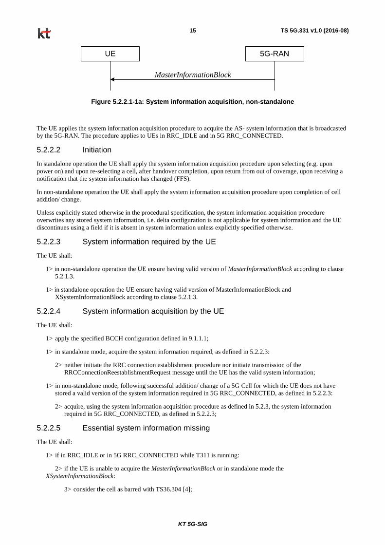
Figure 5.2.2.1-1a: System information acquisition, non-standalone
The UE applies the system information acquisition procedure to acquire the AS- system information that is broadcasted
by the 5G-RAN. The procedure applies to UEs in RRC_IDLE and in 5G RRC_CONNECTED.
5.2.2.2 Initiation
In standalone operation the UE shall apply the system information acquisition procedure upon selecting (e.g. upon
power on) and upon re-selecting a cell, after handover completion, upon return from out of coverage, upon receiving a
notification that the system information has changed (FFS).
In non-standalone operation the UE shall apply the system information acquisition procedure upon completion of cell
addition/ change.
Unless explicitly stated otherwise in the procedural specification, the system information acquisition procedure
overwrites any stored system information, i.e. delta configuration is not applicable for system information and the UE
discontinues using a field if it is absent in system information unless explicitly specified otherwise.
5.2.2.3 System information required by the UE
The UE shall:
1> in non-standalone operation the UE ensure having valid version of MasterInformationBlock according to clause
5.2.1.3.
1> in standalone operation the UE ensure having valid version of MasterInformationBlock and
XSystemInformationBlock according to clause 5.2.1.3.
5.2.2.4 System information acquisition by the UE
The UE shall:
1> apply the specified BCCH configuration defined in 9.1.1.1;
1> in standalone mode, acquire the system information required, as defined in 5.2.2.3:
2> neither initiate the RRC connection establishment procedure nor initiate transmission of the
RRCConnectionReestablishmentRequest message until the UE has the valid system information;
1> in non-standalone mode, following successful addition/ change of a 5G Cell for which the UE does not have
stored a valid version of the system information required in 5G RRC_CONNECTED, as defined in 5.2.2.3:
2> acquire, using the system information acquisition procedure as defined in 5.2.3, the system information
required in 5G RRC_CONNECTED, as defined in 5.2.2.3;
5.2.2.5 Essential system information missing
The UE shall:
1> if in RRC_IDLE or in 5G RRC_CONNECTED while T311 is running:
2> if the UE is unable to acquire the MasterInformationBlock or in standalone mode the
XSystemInformationBlock:
3> consider the cell as barred with TS36.304 [4];
KT 5G-SIG
TS 5G.331 v1.0 (2016-08) 16
5.2.2.6 Actions upon reception of the MasterInformationBlock message
Upon receiving the MasterInformationBlock message the UE shall:
1> apply the configuration included in brsTransmisionPeriod and ePBCHConfiguration.
5.2.2.7 Actions upon reception of the XSystemInformationBlock message
Upon receiving the XSystemInformationBlock message the UE shall:
1> forward the cellidentity to upper layers;
1> apply the default configuration as defined in 9.2.5.
5.3 Connection Control
5.3.1 Introduction
5.3.1.1 RRC connection control in standalone mode
RRC connection establishment involves the establishment of SRB1. 5G-RAN completes RRC connection establishment
prior to completing the establishment of the S1 connection, i.e. prior to receiving the UE context information from the
EPC. Consequently, AS security is not activated during the initial phase of the RRC connection. During this initial
phase of the RRC connection, the 5G-RAN may configure the UE to perform measurement reporting, but the UE only
sends the corresponding measurement reports after successful security activation. However, the UE only accepts a
handover message when security has been activated.
Upon receiving the UE context from the EPC, 5G-RAN activates security (both ciphering and integrity protection)
using the initial security activation procedure. The RRC messages to activate security (command and successful
response) are integrity protected, while ciphering is started only after completion of the procedure. That is, the response
to the message used to activate security is not ciphered, while the subsequent messages (e.g. used to establish SRB2 and
DRBs) are both integrity protected and ciphered.
After having initiated the initial security activation procedure, 5G-RAN initiates the establishment of SRB2 and DRBs,
i.e. 5G-RAN may do this prior to receiving the confirmation of the initial security activation from the UE. In any case,
5G-RAN will apply both ciphering and integrity protection for the RRC connection reconfiguration messages used to
establish SRB2 and DRBs. E-UTRAN should release the RRC connection if the initial security activation and/ or the
radio bearer establishment fails (i.e. security activation and DRB establishment are triggered by a joint S1-procedure,
which does not support partial success).
For SRB2 and DRBs, security is always activated from the start, i.e. the 5G-RAN does not establish these bearers prior
to activating security.
After having initiated the initial security activation procedure, 5G-RAN may configure a UE that supports CA, with one
or more SCells in addition to the PCell that was initially configured during connection establishment. The PCell is used
to provide the security inputs and upper layer system information. SCells are used to provide additional downlink and
uplink radio resources.
For some radio configuration fields, a critical extension has been defined. A switch from the original version of the field
to the critically extended version is allowed using any connection reconfiguration. The UE reverts to the original
version of some critically extended fields upon handover and re-establishment as specified elsewhere in this
specification. Otherwise, switching a field from the critically extended version to the original version is only possible
using the handover or re-establishment procedure with the full configuration option. This also applies for fields that are
critically extended within a release (i.e. original and extended version defined in same release).
5.3.1.1a RRC connection control in non-standalone mode
5G RRC connection establishment involves the establishment of LTE DRB. All 5G RRC messages are ciphered by
LTE PDCP of the given DRB. 5G ciphering is not activated during the initial phase of the RRC connection. During this
initial phase of the RRC connection, the 5G-RAN may configure the UE to perform measurement reporting.

KT 5G-SIG
TS 5G.331 v1.0 (2016-08) 17
For 5G DRBs, ciphering is always activated from the start, i.e. the 5G-RAN does not establish these bearers prior to
activating security.
NOTE1: The ciphering may be activated in the same RRC message the 5G DRBs are established.
5G RRC connection may only be released by releasing the corresponding DRB by E-UTRAN.
5.3.1.2 Security in standalone mode
AS security comprises of the integrity protection of RRC signalling (SRBs) as well as the ciphering of RRC signalling
(SRBs) and user data (DRBs).
RRC handles the configuration of the security parameters which are part of the AS configuration: the integrity
protection algorithm, the ciphering algorithm and two parameters, namely the keyChangeIndicator and the
nextHopChainingCount, which are used by the UE to determine the AS security keys upon handover and/ or connection
re-establishment.
NOTE : Only AES shall be mandatory, other algorithms could be considered for subsequent phases.The integrity
protection algorithm is common for signalling radio bearers SRB1 and SRB2. The ciphering algorithm is common for
all radio bearers (i.e. SRB1, SRB2 and DRBs). Neither integrity protection nor ciphering applies for SRB0.
RRC integrity and ciphering are always activated together, i.e. in one message/ procedure. RRC integrity and ciphering
are never de-activated. However, it is possible to switch to a 'NULL' ciphering algorithm (eea0).
The 'NULL' integrity protection algorithm (eia0) is used only for the UE in limited service mode [TS33.401]. In case
the 'NULL' integrity protection algorithm is used, 'NULL' ciphering algorithm is also used.
NOTE 1: Lower layers discard RRC messages for which the integrity check has failed and indicate the integrity
verification check failure to RRC.
The AS applies three different security keys: one for the integrity protection of RRC signalling (KRRCint), one for the
ciphering of RRC signalling (KRRCenc) and one for the ciphering of user data (KUPenc). All three AS keys are derived
from the 5G KeNB key. The 5G KeNB is based on the KASME key, which is handled by upper layers.
Upon connection establishment new AS keys are derived. No AS-parameters are exchanged to serve as inputs for the
derivation of the new AS keys at connection establishment.
The integrity and ciphering of the RRC message used to perform handover is based on the security configuration used
prior to the handover and is performed by the source5G-RAN.
The integrity and ciphering algorithms can only be changed upon handover. The four AS keys (5G KeNB, KRRCint, KRRCenc
and KUPenc) change upon every handover and connection re-establishment. The keyChangeIndicator is used upon
handover and indicates whether the UE should use the keys associated with the KASME key taken into use with the latest
successful NAS SMC procedure. The nextHopChainingCount parameter is used upon handover and connection re-
establishment by the UE when deriving the new 5G KeNB that is used to generate KRRCint, KRRCenc and KUPenc (see TS
33.401 [11]). An intra cell handover procedure may be used to change the keys in RRC_CONNECTED.
For each radio bearer an independent counter (COUNT, as specified in 5G.323 [8]) is maintained for each direction. For
each DRB, the COUNT is used as input for ciphering. For each SRB, the COUNT is used as input for both ciphering
and integrity protection. It is not allowed to use the same COUNT value more than once for a given security key. In
order to limit the signalling overhead, individual messages/ packets include a short sequence number (PDCP SN, as
specified in 5G.323 [8]). In addition, an overflow counter mechanism is used: the hyper frame number (TX_HFN and
RX_HFN, as specified in 5G.323 [8]). The HFN needs to be synchronized between the UE and the 5G-RAN. The 5G-
RAN is responsible for avoiding reuse of the COUNT with the same RB identity and with the same 5G KeNB, e.g. due to
the transfer of large volumes of data, release and establishment of new RBs. In order to avoid such re-use, the 5G-RAN
may e.g. use different RB identities for successive RB establishments, trigger an intra cell handover or an
RRC_CONNECTED to RRC_IDLE to RRC_CONNECTED transition.
For each SRB, the value provided by RRC to lower layers to derive the 5-bit BEARER parameter used as input for
ciphering and for integrity protection is the value of the corresponding srb-Identity with the MSBs padded with zeroes.

KT 5G-SIG
TS 5G.331 v1.0 (2016-08) 18
5.3.1.2a Security in non-standalone mode
AS security in 5G comprises the ciphering of user data (DRBs).
5G RRC handles the configuration of the security parameters which are part of the AS configuration: the ciphering
algorithm and the 5G KeNB. The ciphering algorithm is common for all radio bearers (DRBs). The ciphering is never de-
activated. However, it is possible to switch to a 'NULL' ciphering algorithm (eea0).
The UE and 5G-RAN applies one KUPenc for the ciphering of user data. This KUPenc is derived from the 5G KeNB.by UE
and 5G-RAN as defined in [9]. The 5G KeNB is derived at the 5G cell by using 5G-RAND, which is a basic random
value used as input into 5G KeNB derivations. The 5G-RAN, delivers the 5G KeNB and selected ciphering algorithm to
the UE only via encrypted link 4G DRB for 5G RRC signalling.
Whenever a 5G cell change takes place, 5G KeNB is derived at the target 5G cell and delivered to the UE.
The 5G-C value is used as freshness input into the 5G KeNB derivations. The 5G-C value is increased by 1 whenever
generating a 5G KeNB for any UE within the 5G cell. 5G AS security keys are refreshed when PDCP COUNTs are about
to wrap around. 5G KeNB* is newly derived by 5G-RAN from the current "5G- C value" and delivered to UE via 5G
RRC signalling. 5G KeNB* is then used as new 5G KeNB for 5G user data. When the UE goes into 5G RRC-IDLE all
keys are deleted from the 5G-RAN. AS key is updated at 5G cell change by indicating in 5G RRC signalling to the UE
the value of the new 5G KeNB generated at new 5G cell.
5.3.1.3 Connected mode mobility
In 5G RRC_CONNECTED, the network controls UE mobility, i.e. the network decides when the UE shall connect to
which 5G cell. For network controlled mobility in 5G RRC_CONNECTED, the 5G cell can be changed using an
RRCConnectionReconfiguration message including the mobilityControlInfo. The network triggers the handover
procedure e.g. based on radio conditions, load. To facilitate this, the network may configure the UE to perform
measurement reporting. The network may also initiate handover blindly, i.e. without having received measurement
reports from the UE.
Before sending the handover message to the UE, the source 5G-RAN prepares one or more target cells. The source 5G-
RAN selects the target 5G cell. The target 5G cell decides which SCells are configured for use after handover.
The target 5G Node generates the message used to perform the handover, i.e. the message including the AS-
configuration to be used in the target cell(s). The source 5G Node transparently (i.e. does not alter values/ content)
forwards the handover message/ information received from the target to the UE. When appropriate, the source 5GNode
may initiate data forwarding for (a subset of) the DRBs.
After receiving the handover message, the UE attempts to access the target 5G cell at the first available RACH occasion
according to Random Access resource selection defined in TS 5G.321 [6], i.e. the handover is asynchronous.
Consequently, when allocating a dedicated preamble for the random access in the target 5G cell, 5G-RAN shall ensure
it is available from the first RACH occasion the UE may use. Upon successful completion of the handover, the UE
sends a message used to confirm the handover.
In RRC_CONNECTED, the network may initiate UE-based mobility, i.e., the 5GNB configures measurement events
for detection of candidate cells and triggering of handover execution in UE-based handover. The 5GNB transmits an
RRCConnectionReconfiguration message including the mobilityControlInfo (list of candidate cells for UE-based
handover). The 5GNB configures a dedicated measurement event for handover execution in UE-based handover
procedure. Upon triggering the measurement event the UE attempts to perform a RRC Connection Reestablishment
procedure in the best candidate cell.
If the target 5GNB does not support the release of RRC protocol which the source 5GNB used to configure the UE, the
target 5GNB may be unable to comprehend the UE configuration provided by the source 5GNB. In this case, the target
5GNB should use the full configuration option to reconfigure the UE for Handover and Re-establishment. Full
configuration option includes an initialization of the radio configuration, which makes the procedure independent of the
configuration used in the source cell(s) with the exception that the security algorithms are continued for the RRC re-
establishment.
After the successful completion of handover, PDCP SDUs may be re-transmitted in the target cell(s). This only applies
for DRBs using RLC-AM mode and for handovers not involving full configuration option. The further details are
specified in TS 5G.323 [8]. After the successful completion of handover not involving full configuration option, the SN
KT 5G-SIG
TS 5G.331 v1.0 (2016-08) 19
and the HFN are reset except for the DRBs using RLC-AM mode (for which both SN and HFN continue). For
reconfigurations involving the full configuration option, the PDCP entities are newly established (SN and HFN do not
continue) for all DRBs irrespective of the RLC mode. The further details are specified in TS 5G.323 [8].One UE
behaviour to be performed upon handover is specified, i.e. this is regardless of the handover procedures used within the
network (e.g. whether the handover includes X2 or S1 signalling procedures).
The source 5G cell should, for some time, maintain a context to enable the UE to return in case of handover failure.
After having detected handover failure, the UE attempts to resume the RRC connection either in the source 5G Cell or
in another cell using the RRC re-establishment procedure. This connection resumption succeeds only if the accessed
cell is prepared, i.e. concerns a cell of the source 5G cell or of another 5G cell towards which handover preparation has
been performed. The cell in which the re-establishment procedure succeeds becomes the PCell while SCells, if
configured, are released.
5.3.2 Void
Editors note: This section covers paging in LTE. It is FFS if paging is introduced in standalone operation.
5.3.3 RRC connection establishment in standalone operation
Editors note: This section is to cover RRC connection establishment in stand-alone operation.
5.3.3.1 General
RRCConnectionSetup
RRCConnectionRequest
UE 5G-RAN
RRCConnectionSetupComplete
Figure 5.3.3.1-1: RRC connection establishment, successful
RRCConnectionReject
RRCConnectionRequest
UE 5G-RAN
Figure 5.3.3.1-2: RRC connection establishment, network reject
The purpose of this procedure is to establish an RRC connection in standalone operation. RRC connection
establishment involves SRB1 establishment. The procedure is also used to transfer the initial NAS dedicated
information/ message from the UE to 5G-RAN.
5GRAN applies the procedure as follows:
- to establish SRB1 only.

KT 5G-SIG
TS 5G.331 v1.0 (2016-08) 20
5.3.3.2 Initiation
The UE initiates the procedure when upper layers request establishment of an RRC connection while the UE is in
RRC_IDLE.
Upon initiation of the procedure, the UE shall:
1> apply the default physical channel configuration as specified in 9.2.4;
1> apply the default MAC main configuration as specified in 9.2.2;
1> apply the CCCH configuration as specified in 9.1.1.2;
1> start timer T300;
1> initiate transmission of the RRCConnectionRequest message in accordance with 5.3.3.3;
5.3.3.3 Actions related to transmission of RRCConnectionRequest message
The UE shall set the contents of RRCConnectionRequest message as follows:
1> set the ue-Identity as follows:
2> if upper layers provide an S-TMSI:
3> set the ue-Identity to the value received from upper layers;
2> else:
3> draw a random value in the range 0 .. 240
-1 and set the ue-Identity to this value;
NOTE 1: Upper layers provide the S-TMSI if the UE is registered in the TA of the current cell.
The UE shall submit the RRCConnectionRequest message to lower layers for transmission.
5.3.3.4 Reception of the RRCConnectionSetup by the UE
NOTE: Prior to this, lower layer signalling is used to allocate a C-RNTI. For further details see TS 5G.321 [6];
The UE shall:
1> perform the radio resource configuration procedure in accordance with the received
radioResourceConfigDedicated and as specified in 5.3.10;
1> stop timer T300;
1> stop timer T302, if running;
1> perform the actions as specified in 5.3.3.7;
1> enter RRC_CONNECTED;
1> consider the current cell to be the PCell;
1> set the content of RRCConnectionSetupComplete message as follows:
2> set the selectedPLMN-Identity to the PLMN selected by upper layers (see TS 23.122 [10], TS 24.301 [12])
from the PLMN(s) included in the plmn-IdentityList in xSystemInformationBlock;
2> if upper layers provide the 'Registered MME', include and set the registeredMME as follows:
3> if the PLMN identity of the 'Registered MME' is different from the PLMN selected by the upper layers:
4> include the plmnIdentity in the registeredMME and set it to the value of the PLMN identity in the
'Registered MME' received from upper layers;

KT 5G-SIG
TS 5G.331 v1.0 (2016-08) 21
3> set the mmegi and the mmec to the value received from upper layers;
2> if upper layers provided the 'Registered MME':
3> include and set the gummei-Type to the value provided by the upper layers;
2> set the dedicatedInfoNAS to include the information received from upper layers;
2> submit the RRCConnectionSetupComplete message to lower layers for transmission, upon which the
procedure ends;
5.3.3.5 Cell selection while T300, T302 is running
The UE shall:
1> if cell selection occurs while T300, T302:
2> if timer T302:
3> stop timer;
3> perform the actions as specified in 5.3.3.7;
2> if timer T300 is running:
3> stop timer T300;
3> reset MAC, release the MAC configuration and re-establish RLC for all RBs that are established;
3> inform upper layers about the failure to establish the RRC connection
5.3.3.6 T300 expiry
The UE shall:
1> if timer T300 expires:
2> reset MAC, release the MAC configuration and re-establish RLC for all RBs that are established;
2> inform upper layers about the failure to establish the RRC connection, upon which the procedure ends;
5.3.3.7 T302 expiry or stop
The UE shall:
1> if timer T302 expires or is stopped:
2> inform upper layers about barring alleviation for mobile terminating access;
5.3.3.8 Reception of the RRCConnectionReject by the UE
The UE shall:
1> stop timer T300;
1> reset MAC and release the MAC configuration;
1> start timer T302, with the timer value set to the waitTime;
1> inform upper layers about the failure to establish the RRC connection, upon which the procedure ends;
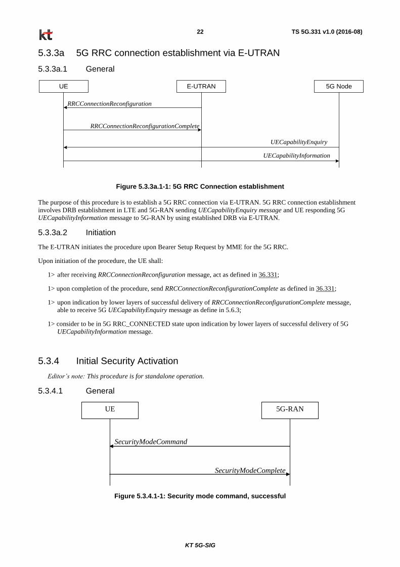
KT 5G-SIG
TS 5G.331 v1.0 (2016-08) 22
5.3.3a 5G RRC connection establishment via E-UTRAN
5.3.3a.1 General
UE E-UTRAN 5G Node
RRCConnectionReconfiguration
RRCConnectionReconfigurationComplete
UECapabilityInformation
UECapabilityEnquiry
Figure 5.3.3a.1-1: 5G RRC Connection establishment
The purpose of this procedure is to establish a 5G RRC connection via E-UTRAN. 5G RRC connection establishment
involves DRB establishment in LTE and 5G-RAN sending UECapabilityEnquiry message and UE responding 5G
UECapabilityInformation message to 5G-RAN by using established DRB via E-UTRAN.
5.3.3a.2 Initiation
The E-UTRAN initiates the procedure upon Bearer Setup Request by MME for the 5G RRC.
Upon initiation of the procedure, the UE shall:
1> after receiving RRCConnectionReconfiguration message, act as defined in 36.331;
1> upon completion of the procedure, send RRCConnectionReconfigurationComplete as defined in 36.331;
1> upon indication by lower layers of successful delivery of RRCConnectionReconfigurationComplete message,
able to receive 5G UECapabilityEnquiry message as define in 5.6.3;
1> consider to be in 5G RRC_CONNECTED state upon indication by lower layers of successful delivery of 5G
UECapabilityInformation message.
5.3.4 Initial Security Activation
Editor’s note: This procedure is for standalone operation.
5.3.4.1 General
SecurityModeComplete
SecurityModeCommand
UE 5G-RAN
Figure 5.3.4.1-1: Security mode command, successful

KT 5G-SIG
TS 5G.331 v1.0 (2016-08) 23
SecurityModeFailure
SecurityModeCommand
UE 5G-RAN
Figure 5.3.4.1-2: Security mode command, failure
The purpose of this procedure is to activate AS security upon RRC connection establishment in standalone operation.
5.3.4.2 Initiation
5G-RAN initiates the security mode command procedure to a UE in RRC_CONNECTED. Moreover, 5G-RAN applies
the procedure as follows:
- when only SRB1 is established, i.e. prior to establishment of SRB2 and/ or DRBs.
5.3.4.3 Reception of the SecurityModeCommand by the UE
The UE shall:
1> derive the 5G KeNB key, as specified in TS 33.401 [11];
1> derive the KRRCint key associated with the integrityProtAlgorithm indicated in the SecurityModeCommand
message, as specified in TS 33.401 [11];
1> request lower layers to verify the integrity protection of the SecurityModeCommand message, using the
algorithm indicated by the integrityProtAlgorithm as included in the SecurityModeCommand message and the
KRRCint key;
1> if the SecurityModeCommand message passes the integrity protection check:
2> derive the KRRCenc key and the KUPenc key associated with the cipheringAlgorithm indicated in the
SecurityModeCommand message, as specified in TS 33.401 [11];
2> configure lower layers to apply integrity protection using the indicated algorithm and the KRRCint key
immediately, i.e. integrity protection shall be applied to all subsequent messages received and sent by the UE,
including the SecurityModeComplete message;
2> configure lower layers to apply ciphering using the indicated algorithm, the KRRCenc key and the KUPenc key
after completing the procedure, i.e. ciphering shall be applied to all subsequent messages received and sent
by the UE, except for the SecurityModeComplete message which is sent unciphered;
2> consider AS security to be activated;
2> submit the SecurityModeComplete message to lower layers for transmission, upon which the procedure ends;
1> else:
2> continue using the configuration used prior to the reception of the SecurityModeCommand message, i.e.
neither apply integrity protection nor ciphering.
2> submit the SecurityModeFailure message to lower layers for transmission, upon which the procedure ends;

KT 5G-SIG
TS 5G.331 v1.0 (2016-08) 24
5.3.5 RRC connection reconfiguration
5.3.5.1 General
UE 5G-RAN
RRCConnectionReconfiguration
RRCConnectionReconfigurationComplete
Figure 5.3.4.1-1: 5G RRC Connection reconfiguration
UE 5G-RAN
RRCConnectionReconfiguration
RRC Connection re-establishment
Figure 5.3.4.1-2: 5G RRC Connection reconfiguration, failure
The purpose of this procedure is to modify a 5G RRC connection, e.g. to establish/ modify/ release RBs, to perform cell
change, to setup/ modify/ release measurements, to activate 5G ciphering, provide system information. As part of the
procedure, NAS dedicated information may be transferred from 5G-RAN to the UE.
5.3.5.2 Initiation
5G-RAN may initiate the 5G RRC connection reconfiguration procedure to a UE in 5G RRC_CONNECTED. 5G-RAN
applies the procedure as follows:
- the mobilityControlInfo is included only when AS-security has been activated, and SRB2 with at least one DRB
are setup and not suspended;
- ‘the establishment of RBs is included only when 5G ciphering has been activated;
- the addition of SCells is performed only when AS security has been activated;
5.3.5.3 Reception of an RRCConnectionReconfiguration not including the mobilityControlInfo by the UE
If the RRCConnectionReconfiguration message does not include the mobilityControlInfo and the UE is able to comply
with the configuration included in this message, the UE shall:
1> if operating in non-standalone mode and the RRCConnectionReconfiguration message includes the
configRelease:
2> perform the radio configuration procedure as specified in section 5.3.5.9;
1> if this is the first RRCConnectionReconfiguration message after successful completion of the RRC Connection
Re-establishment procedure:
2> re-establish PDCP for SRB2 and for all DRBs that are established, if any;
2> re-establish RLC for SRB2 and for all DRBs that are established, if any

KT 5G-SIG
TS 5G.331 v1.0 (2016-08) 25
2> if the RRCConnectionReconfiguration message includes the fullConfig:
3> perform the radio configuration procedure as specified in section 5.3.5.8;
2> if the RRCConnectionReconfiguration message includes the radioResourceConfigDedicated:
3> perform the radio resource configuration procedure as specified in 5.3.10;
2> resume SRB2 and all DRBs that are suspended, if any;
NOTE 1: The handling of the radio bearers after the successful completion of the PDCP re-establishment, e.g. the
re-transmission of unacknowledged PDCP SDUs (as well as the associated status reporting), the handling of the
SN and the HFN, is specified in TS 5G.323.
NOTE 2: The UE may discard SRB2 messages and data that it receives prior to completing the reconfiguration
used to resume these bearers.
1> else:
2> if the RRCConnectionReconfiguration message includes the radioResourceConfigDedicated:
3> perform the radio resource configuration procedure as specified in 5.3.10;
NOTE 3: If the RRCConnectionReconfiguration message includes the establishment of radio bearers other than
SRB1, the UE may start using these radio bearers immediately, i.e. there is no need to wait for an outstanding
acknowledgment of the SecurityModeComplete message.
1> if the received RRCConnectionReconfiguration includes the sCellToReleaseList:
2> perform SCell release as specified in 5.3.10.3a;
1> if the received RRCConnectionReconfiguration includes the sCellToAddModList:
2> perform SCell addition or modification as specified in 5.3.10.3b;
1> if the RRCConnectionReconfiguration message includes the measConfig:
2> perform the measurement configuration procedure as specified in 5.5.2;
1> perform the measurement identity autonomous removal as specified in 5.5.2.2a;
1> submit the RRCConnectionReconfigurationComplete message to lower layers for transmission using the new
configuration, upon which the procedure ends;
5.3.5.4 Reception of an RRCConnectionReconfiguration including the mobilityControlInfo by the UE (handover)
If the RRCConnectionReconfiguration message includes the mobilityControlInfo and the UE is able to comply with the
configuration included in this message, the UE shall:
1> if the targetPhysCellId is included:
2> stop timer T310, if running;
2> stop timer T312, if running;
2> start timer T304 with the timer value set to t304, as included in the mobilityControlInfo;
2> if the carrierFreq is included:
3> consider the target 5G Cell to be one on the frequency indicated by the carrierFreq with a physical cell
identity indicated by the targetPhysCellId;
2> else:
3> consider the target 5G Cell to be one on the frequency of the source 5G Cell with a physical cell identity
indicated by the targetPhysCellId;

KT 5G-SIG
TS 5G.331 v1.0 (2016-08) 26
2> start synchronising to the DL of the target 5G Cell;
NOTE 1: The UE should perform the handover as soon as possible following the reception of the RRC message
triggering the handover, which could be before confirming successful reception (HARQ and ARQ) of this
message.
2> reset MAC;
2> re-establish PDCP for all RBs that are established;
NOTE 2: The handling of the radio bearers after the successful completion of the PDCP re-establishment, e.g. the
re-transmission of unacknowledged PDCP SDUs (as well as the associated status reporting), the handling
of the SN and the HFN, is specified in 5G.323 [8].
2> re-establish RLC for all RBs that are established;
2> apply the value of the newUE-Identity as the C-RNTI;
2> if the RRCConnectionReconfiguration message includes the fullConfig:
3> perform the radio configuration procedure as specified in section 5.3.5.8;
2> configure lower layers in accordance with the received radioResourceConfigCommon;
2> configure lower layers in accordance with any additional fields, not covered in the previous, if included in the
received mobilityControlInfo;
2> if the RRCConnectionReconfiguration message includes the radioResourceConfigDedicated:
3> perform the radio resource configuration procedure as specified in 5.3.10;
2> if operating in non-Standalone mode:
3> if the RRCConnectionReconfiguration message includes the securityConfigIWK:
3> update the 5G KeNB key based on the new 5G KeNB* received in the securityConfigIWK;
3> If the securityConfigIWK also includes new ciphering algorithm
4> Update ciphering algorithm based on the new ciphering algorithm received in the securityConfigIWK;
2> else
3> if the keyChangeIndicator received in the securityConfigHO is set to TRUE:
4> update the 5G KeNB key based on the KASME key taken into use with the latest successful NAS SMC
procedure, as specified in TS 33.401 [11];
3> else:
4> update the 5G KeNB key based on the current 5G KeNB or the NH, using the nextHopChainingCount
value indicated in the securityConfigHO, as specified in TS 33.401 [11];
3> store the nextHopChainingCount value;
2> if the securityAlgorithmConfig is included in the securityConfigHO:
3> derive the KRRCint key associated with the integrityProtAlgorithm, as specified in TS 33.401 [11];
3> derive the KRRCenc key and the KUPenc key associated with the cipheringAlgorithm, as specified in TS
33.401 [11];
2> else:
3> derive the KRRCint key associated with the current integrity algorithm, as specified in TS 33.401 [11];
3> derive the KRRCenc key and the KUPenc key associated with the current ciphering algorithm, as
specified in TS 33.401 [11];

KT 5G-SIG
TS 5G.331 v1.0 (2016-08) 27
2> configure lower layers to apply the integrity protection algorithm and the KRRCint key, i.e. the integrity
protection configuration shall be applied to all subsequent messages received and sent by the UE, including
the message used to indicate the successful completion of the procedure;
2> configure lower layers to apply the ciphering algorithm, the KRRCenc key and the KUPenc key, i.e. the
ciphering configuration shall be applied to all subsequent messages received and sent by the UE, including
the message used to indicate the successful completion of the procedure;
2> if the received RRCConnectionReconfiguration includes the sCellToReleaseList:
3> perform SCell release as specified in 5.3.10.3a;
2> if the received RRCConnectionReconfiguration includes the sCellToAddModList:
3> perform SCell addition or modification as specified in 5.3.10.3b;
2> perform the measurement related actions as specified in 5.5.6.1;
2> if the RRCConnectionReconfiguration message includes the measConfig:
3> perform the measurement configuration procedure as specified in 5.5.2;
2> perform the measurement identity autonomous removal as specified in 5.5.2.2a;
2> submit the RRCConnectionReconfigurationComplete message to lower layers for transmission;
2> if MAC successfully completes the random access procedure:
3> stop timer T304;
3> consider the 5G-cell as the Pcell for 5G connection
3> apply the parts of the CQI reporting configuration, the scheduling request configuration and the sounding
RS configuration that do not require the UE to know the SFN of the target 5G Cell, if any;
3> apply the parts of the measurement and the radio resource configuration that require the UE to know the
SFN of the target 5G Cell (e.g., periodic CQI reporting, scheduling request configuration, sounding RS
configuration), if any, upon acquiring the SFN of the target 5G Cell;
NOTE 3: Whenever the UE shall setup or reconfigure a configuration in accordance with a field that is received it
applies the new configuration, except for the cases addressed by the above statements.
2> the procedure ends;
NOTE 4: The UE is not required to determine the SFN of the target 5G Cell by acquiring system information from
that cell before performing RACH access in the target 5G Cell.
1> else (i.e., the candidateCellInfoList is included):
2> apply the measurement configuration for UE based handover execution;
2> if an event for UE based handover execution is triggered, the UE shall perform RRC Connection
Reestablishment procedure with one of the candidate cells with the highest RSRP as specified in 5.3.7.
5.3.5.5 Reconfiguration failure
The UE shall:
1> if the UE is unable to comply with (part of) the configuration included in the RRCConnectionReconfiguration
message:
2> continue using the configuration used prior to the reception of RRCConnectionReconfiguration message;
2> if security has not been activated (operating in standalone mode or non-standalone mode):
4> perform the actions upon leaving RRC_CONNECTED as specified in 5.3.12, with release cause other;
2> else:
KT 5G-SIG
TS 5G.331 v1.0 (2016-08) 28
4> initiate the connection re-establishment procedure as specified in 5.3.7, upon which the connection
reconfiguration procedure ends;
NOTE 1: The UE may apply above failure handling also in case the RRCConnectionReconfiguration message
causes a protocol error for which the generic error handling as defined in 5.7 specifies that the UE shall
ignore the message.
NOTE 2: If the UE is unable to comply with part of the configuration, it does not apply any part of the
configuration, i.e. there is no partial success/ failure.
5.3.5.6 T304 expiry (handover failure)
If operating in standalone mode the UE shall:
1> if T304 expires (handover failure):
NOTE 1: Following T304 expiry any dedicated preamble, if provided within the rach-ConfigDedicated, is not
available for use by the UE anymore.
2> revert back to the configuration used in the source PCell, excluding the configuration configured by the
physicalConfigDedicated and the mac-MainConfig;;
2> initiate the connection re-establishment procedure as specified in 5.3.7, upon which the RRC connection
reconfiguration procedure ends;
Editor’s note: Handover failure in non-standalone operation is FFS.
5.3.5.8 Radio Configuration involving full configuration option
The UE shall:
1> release/ clear all current dedicated radio configurations except the C-RNTI, the security configuration and the
PDCP, RLC, logical channel configurations for the RBs;
NOTE 1: Radio configuration is not just the resource configuration but includes other configurations like
MeasConfig and OtherConfig.
1> if the RRCConnectionReconfiguration message includes the mobilityControlInfo:
2> release/ clear all current dedicated radio configurations;
1> if operating in standalone mode:
2> use the default values specified in 9.2.5 for timer T310, T311 and constant N310, N311;
2> apply the default physical channel configuration as specified in 9.2.4;
2> apply the default MAC main configuration as specified in 9.2.2;
1> for each srb-Identity value included in the srb-ToAddModList (SRB reconfiguration):
2> apply the specified configuration defined in 9.1.2 for the corresponding SRB;
2> apply the corresponding default RLC configuration for the SRB specified in 9.2.1.1 for SRB1 or in 9.2.1.2
for SRB2;
2> apply the corresponding default logical channel configuration for the SRB as specified in 9.2.1.1 for SRB1 or
in 9.2.1.2 for SRB2;
NOTE 2: This is to get the SRBs (SRB1 and SRB2 for handover and SRB2 for reconfiguration after
reestablishment) to a known state from which the reconfiguration message can do further configuration
1> for each eps-BearerIdentity value included in the drb-ToAddModList that is part of the current UE configuration:
2> release the PDCP entity;
2> release the RLC entity or entities;

KT 5G-SIG
TS 5G.331 v1.0 (2016-08) 29
2> release the DTCH logical channel;
2> release the drb-identity;
NOTE 3: This will retain the eps-bearerIdentity but remove the DRBs including drb-identity of these bearers from
the current UE configuration and trigger the setup of the DRBs within the AS in Section 5.3.10.3 using
the new configuration. The eps-bearerIdentity acts as the anchor for associating the released and re-setup
DRB.
1> for each eps-BearerIdentity value that is part of the current UE configuration but not part of the drb-
ToAddModList:
2> perform DRB release as specified in 5.3.10.2;
5.3.5.9 Radio Configuration involving configuration release option
The UE shall:
1> release/ clear all current dedicated radio configurations including the C-RNTI, the security configuration and the
PDCP, RLC, logical channel configurations for the RBs;
1> stop all action related to 5G.
NOTE 1: Radio configuration is not just the resource configuration but includes other configurations like
MeasConfig and OtherConfig.
5.3.6 Counter Check
5.3.6.1 General
CounterCheckResponse
CounterCheck
UE 5G-RAN
Figure 5.3.6.1-1: Counter check procedure
The counter check procedure is used by 5G-RAN to request the UE to verify the amount of data sent/ received on each
DRB. More specifically, the UE is requested to check if, for each DRB, the most significant bits of the COUNT match
with the values indicated by 5G-RAN.
NOTE: The procedure enables 5G-RAN to detect packet insertion by an intruder (a 'man in the middle').
5.3.6.2 Initiation
5G-RAN initiates the procedure by sending a CounterCheck message.
NOTE: 5G-RAN may initiate the procedure when any of the COUNT values reaches a specific value.
5.3.6.3 Reception of the CounterCheck message by the UE
Upon receiving the CounterCheck message, the UE shall:
1> for each DRB that is established:
2> if no COUNT exists for a given direction (uplink or downlink) because it is a uni-directional bearer
configured only for the other direction:

KT 5G-SIG
TS 5G.331 v1.0 (2016-08) 30
3> assume the COUNT value to be '0' for the unused direction;
2> if the drb-Identity is not included in the drb-CountMSB-InfoList:
3> include the DRB in the drb-CountInfoList in the CounterCheckResponse message by including the drb-
Identity, the count-Uplink and the count-Downlink set to the value of the corresponding COUNT;
2> else if, for at least one direction, the most significant bits of the COUNT are different from the value
indicated in the drb-CountMSB-InfoList:
3> include the DRB in the drb-CountInfoList in the CounterCheckResponse message by including the drb-
Identity, the count-Uplink and the count-Downlink set to the value of the corresponding COUNT;
1> for each DRB that is included in the drb-CountMSB-InfoList in the CounterCheck message that is not established:
2> include the DRB in the drb-CountInfoList in the CounterCheckResponse message by including the drb-
Identity, the count-Uplink and the count-Downlink with the most significant bits set identical to the
corresponding values in the drb-CountMSB-InfoList and the least significant bits set to zero;
1> submit the CounterCheckResponse message to lower layers for transmission upon which the procedure ends;
5.3.7 RRC connection re-establishment
Editor’s note: This procedure is for standalone operation.
5.3.7.1 General
RRCConnectionReestablishmentRequest
UE 5G-RAN
RRCConnectionReestablishment
RRCConnectionReestablishmentComplete
Figure 5.3.7.1-1: RRC connection re-establishment, successful
RRCConnectionReestablishmentRequest
UE 5G-RAN
RRCConnectionReestablishmentReject
Figure 5.3.7.1-2: RRC connection re-establishment, failure
The purpose of this procedure is to re-establish the RRC connection in standalone operation which involves the
resumption of SRB1 operation, the re-activation of security and the configuration of only the PCell.
A UE in RRC_CONNECTED, for which security has been activated, may initiate the procedure in order to continue the
RRC connection. The connection re-establishment succeeds only if the concerned cell is prepared i.e. has a valid UE
KT 5G-SIG
TS 5G.331 v1.0 (2016-08) 31
context. In case 5G-RAN accepts the re-establishment, SRB1 operation resumes while the operation of other radio
bearers remains suspended. If AS security has not been activated, the UE does not initiate the procedure but instead
moves to RRC_IDLE directly.
5G-RAN applies the procedure as follows:
- to reconfigure SRB1 and to resume data transfer only for this RB;
- to re-activate AS security without changing algorithms.
5.3.7.2 Initiation
The UE shall only initiate the procedure when AS security has been activated. The UE initiates the procedure when one
of the following conditions is met:
1> upon detecting radio link failure, in accordance with 5.3.11; or
1> upon UE-based handover execution in accordance with 5.3.5.4; or
1> upon handover failure, in accordance with 5.3.5.6; or
1> upon integrity check failure indication from lower layers; or
1> upon an RRC connection reconfiguration failure, in accordance with 5.3.5.5;
Upon initiation of the procedure, the UE shall:
1> stop timer T310, if running;
1> stop timer T312, if running;
1> start timer T311;
1> suspend all RBs except SRB0;
1> reset MAC;
1> release the SCell(s), if configured, in accordance with 5.3.10.3a;
1> apply the default physical channel configuration as specified in 9.2.3;
1> apply the default MAC main configuration as specified in 9.2.2;
1> start to access to the best target cell upon UE-based handover execution or perform cell selection in accordance
with the cell selection process as specified in 3GPP TS 36.304 [4];
5.3.7.3 Actions following cell selection while T311 is running
Upon selecting a suitable 5G-RAN cell, the UE shall:
1> stop timer T311;
1> start timer T301;
1> apply the timeAlignmentTimer;
1> initiate transmission of the RRCConnectionReestablishmentRequest message in accordance with 5.3.7.4;
NOTE: This procedure applies also if the UE returns to the source or this procedure applies also if the UE
accesses to the best target cell upon UE-based handover execution..
5.3.7.4 Actions related to transmission of RRCConnectionReestablishmentRequest message
The UE shall set the contents of RRCConnectionReestablishmentRequest message as follows:
1> set the ue-Identity as follows:

KT 5G-SIG
TS 5G.331 v1.0 (2016-08) 32
2> set the c-RNTI to the C-RNTI used in the source PCell (UE-based handover execution or handover failure) or
used in the PCell in which the trigger for the re-establishment occurred (other cases);
2> set the physCellId to the physical cell identity of the source PCell (UE-based handover execution or handover
failure) or of the PCell in which the trigger for the re-establishment occurred (other cases);
2> set the shortMAC-I to the 16 least significant bits of the MAC-I calculated:
3> over the ASN.1 encoded as per section 8 (i.e., a multiple of 8 bits) VarShortMAC-Input;
3> with the KRRCint key and integrity protection algorithm that was used in the source PCell (UE-based
handover execution or handover failure) or of the PCell in which the trigger for the re-establishment
occurred (other cases); and
3> with all input bits for COUNT, BEARER and DIRECTION set to binary ones;
1> set the reestablishmentCause as follows:
2> if the re-establishment procedure was initiated due to reconfiguration failure as specified in 5.3.5.5 (the UE is
unable to comply with the reconfiguration):
3> set the reestablishmentCause to the value reconfigurationFailure;
2> else if the re-establishment procedure was initiated due to UE-based handover execution as specified in
5.3.5.4:
3> set the reestablishmentCause to the value ‘ueBasedHandoverExecution’;
2> else if the re-establishment procedure was initiated due to handover failure as specified in 5.3.5.6:
3> set the reestablishmentCause to the value handoverFailure;
2> else:
3> set the reestablishmentCause to the value otherFailure;
The UE shall submit the RRCConnectionReestablishmentRequest message to lower layers for transmission.
5.3.7.5 Reception of the RRCConnectionReestablishment by the UE
NOTE 1: Prior to this, lower layer signalling is used to allocate a C-RNTI. For further details see 5G.321 [6];
The UE shall:
1> stop timer T301;
1> re-establish PDCP for SRB1;
1> re-establish RLC for SRB1;
1> perform the radio resource configuration procedure in accordance with the received
radioResourceConfigDedicated and as specified in 5.3.10;
1> resume SRB1;
NOTE 2: 5GRAN should not transmit any message on SRB1 prior to receiving the
RRCConnectionReestablishmentComplete message.
1> update the 5G KeNB key based on the KASME key to which the current 5G KeNB is associated, using the
nextHopChainingCount value indicated in the RRCConnectionReestablishment message, as specified in TS
33.401 [11];
1> store the nextHopChainingCount value;
1> derive the KRRCint key associated with the previously configured integrity algorithm, as specified in TS 33.401
[11];

KT 5G-SIG
TS 5G.331 v1.0 (2016-08) 33
1> derive the KRRCenc key and the KUPenc key associated with the previously configured ciphering algorithm, as
specified in TS 33.401 [11];
1> configure lower layers to activate integrity protection using the previously configured algorithm and the KRRCint
key immediately, i.e., integrity protection shall be applied to all subsequent messages received and sent by the
UE, including the message used to indicate the successful completion of the procedure;
1> configure lower layers to apply ciphering using the previously configured algorithm, the KRRCenc key and the
KUPenc key immediately, i.e., ciphering shall be applied to all subsequent messages received and sent by the UE,
including the message used to indicate the successful completion of the procedure;
1> perform the measurement related actions as specified in 5.5.6.1;
1> perform the measurement identity autonomous removal as specified in 5.5.2.2a;
1> submit the RRCConnectionReestablishmentComplete message to lower layers for transmission;
1> the procedure ends;
5.3.7.6 T311 expiry
Upon T311 expiry, the UE shall:
1> perform the actions upon leaving RRC_CONNECTED as specified in 5.3.12, with release cause 'RRC
connection failure';
5.3.7.7 T301 expiry or selected cell no longer suitable
The UE shall:
1> if timer T301 expires; or
1> if the selected cell becomes no longer suitable according to the cell selection:
2> perform the actions upon leaving RRC_CONNECTED as specified in 5.3.12, with release cause 'RRC
connection failure';
5.3.7.8 Reception of RRCConnectionReestablishmentReject by the UE
Upon receiving the RRCConnectionReestablishmentReject message, the UE shall:
1> perform the actions upon leaving RRC_CONNECTED as specified in 5.3.12, with release cause 'RRC
connection failure';
5.3.8 RRC connection release
5.3.8.1 General
RRCConnectionRelease
UE 5G Node
Figure 5.3.8.1-1: RRC connection release, successful
The purpose of this procedure is to release the RRC connection in standalone operation, which includes the release of
the established radio bearers as well as all radio resources.
5.3.8.2 Initiation
5G-RAN initiates the RRC connection release procedure to a UE in RRC_CONNECTED.

KT 5G-SIG
TS 5G.331 v1.0 (2016-08) 34
5.3.8.3 Reception of the RRCConnectionRelease by the UE
The UE shall:
1> delay the following actions defined in this sub-clause 60 ms from the moment the RRCConnectionRelease
message was received or optionally when lower layers indicate that the receipt of the RRCConnectionRelease
message has been successfully acknowledged, whichever is earlier;
1> perform the actions upon leaving RRC_CONNECTED as specified in 5.3.12;
5.3.9 Void
5.3.10 Radio resource configuration
5.3.10.0 General
The UE shall:
1> if the received radioResourceConfigDedicated includes the srb-ToAddModList:
2> perform the SRB addition or reconfiguration as specified in 5.3.10.1;
1> if the received radioResourceConfigDedicated includes the drb-ToReleaseList:
2> perform DRB release as specified in 5.3.10.2;
1> if the received radioResourceConfigDedicated includes the drb-ToAddModList:
2> perform DRB addition or reconfiguration as specified in 5.3.10.3;
1> if the received radioResourceConfigDedicated includes the mac-MainConfig:
2> perform MAC main reconfiguration as specified in 5.3.10.4;
1> if the received radioResourceConfigDedicated includes the physicalConfigDedicated:
2> reconfigure the physical channel configuration as specified in 5.3.10.6.
1> if the received radioResourceConfigDedicated includes the rach-ConfigDedicated:
2> reconfigure the random access channel configuration as specified in 5.3.10.7.
1> if the received radioResourceConfigDedicated includes the rlf-TimersAndConstants:
2> reconfigure the values of timers and constants as specified in 5.3.10.7
5.3.10.1 Void
The UE shall:
1> for each srb-Identity value included in the srb-ToAddModList that is not part of the current UE configuration
(SRB establishment):
2> apply the specified configuration defined in 9.1.2 for the corresponding SRB;
2> establish a PDCP entity and configure it with the current security configuration, if applicable;
2> establish an RLC entity in accordance with the received rlc-Config;
2> establish a DCCH logical channel in accordance with the received logicalChannelConfig and with the logical
channel identity set in accordance with 9.1.2;
1> for each srb-Identity value included in the srb-ToAddModList that is part of the current UE configuration (SRB
reconfiguration):
KT 5G-SIG
TS 5G.331 v1.0 (2016-08) 35
2> reconfigure the RLC entity in accordance with the received rlc-Config;
2> reconfigure the DCCH logical channel in accordance with the received logicalChannelConfig;
5.3.10.2 DRB release
The UE shall:
1> for each drb-Identity value included in the drb-ToReleaseList that is part of the current UE configuration (DRB
release); or
1> for each drb-identity value that is to be released as the result of full configuration option according to 5.3.5.8:
2> release the PDCP entity;
2> release the RLC entity or entities;
2> release the DTCH logical channel;
1> if the procedure was triggered due to handover:
2> indicate the release of the DRB(s) and the eps-BearerIdentity of the released DRB(s) to upper layers after
successful handover;
1> else:
2> indicate the release of the DRB(s) and the eps-BearerIdentity of the released DRB(s) to upper layers
immediately.
NOTE: The UE does not consider the message as erroneous if the drb-ToReleaseList includes any drb-Identity
value that is not part of the current UE configuration.
5.3.10.3 DRB addition/ modification
The UE shall:
1> for each drb-Identity value included in the drb-ToAddModList that is not part of the current UE configuration
(DRB establishment including the case when full configuration option is used):
2> establish a PDCP entity and configure it with the current security configuration and in accordance with the
received pdcp-Config;
2> establish an RLC entity or entities in accordance with the received rlc-Config;
2> establish a DTCH logical channel in accordance with the received logicalChannelIdentity and the received
logicalChannelConfig;
1> if the RRCConnectionReconfiguration message includes the fullConfig IE:
2> associate the established DRB with corresponding included eps-BearerIdentity;
1> else:
2> indicate the establishment of the DRB(s) and the eps-BearerIdentity of the established DRB(s) to upper
layers;
1> for each drb-Identity value included in the drb-ToAddModList that is part of the current UE configuration (DRB
reconfiguration):
2> if the pdcp-Config is included:
3> reconfigure the PDCP entity in accordance with the received pdcp-Config;
2> if the rlc-Config is included:
3> reconfigure the RLC entity or entities in accordance with the received rlc-Config;
2> if the logicalChannelConfig is included:
KT 5G-SIG
TS 5G.331 v1.0 (2016-08) 36
3> reconfigure the DTCH logical channel in accordance with the received logicalChannelConfig;
NOTE: Removal and addition of the same drb-Identity in single radioResourceConfiguration is not supported.
5.3.10.3a SCell release
The UE shall:
1> if the release is triggered by reception of the sCellToReleaseList:
2> for each sCellIndex value included in the sCellToReleaseList:
3> if the current UE configuration includes an SCell with value sCellIndex:
4> release the SCell;
5.3.10.3b SCell addition/ modification
The UE shall:
1> for each sCellIndex value included in the sCellToAddModList that is not part of the current UE configuration
(SCell addition):
2> add the SCell, corresponding to the cellIdentification, in accordance with the received
radioResourceConfigDedicatedSCell;
2> configure lower layers to consider the SCell to be in activated state;
2> for each measId included in the measIdList within VarMeasConfig:
3> if SCells are not applicable for the associated measurement; and
3> if the concerned SCell is included in cellsTriggeredList defined within the VarMeasReportList for this
measId:
4> remove the concerned SCell from cellsTriggeredList defined within the VarMeasReportList for this
measId;
1> for each sCellIndex value included in the sCellToAddModList that is part of the current UE configuration (SCell
modification):
2> modify the SCell configuration in accordance with the received radioResourceConfigDedicatedSCell;
5.3.10.4 MAC main reconfiguration
The UE shall:
1> reconfigure the MAC main configuration in accordance with the received mac-MainConfig;
5.3.10.5 Void
5.3.10.6 Physical channel reconfiguration
The UE shall:
1> reconfigure the physical channel configuration in accordance with the received physicalConfigDedicated;
5.3.10.7 Radio Link Failure Timers and Constants reconfiguration
The UE shall:
1> if the received rlf-TimersAndConstants is set to release:

KT 5G-SIG
TS 5G.331 v1.0 (2016-08) 37
2> use values for timers T301, T310, T311 and constants N310, N311, as included in default-
TimersAndConstants in 9.2.;
1> else:
2> reconfigure the value of timers and constants in accordance with received rlf-TimersAndConstants;
5.3.10.8 Random access channel reconfiguration
The UE shall:
1> reconfigure the random access channel configuration in accordance with the received rach-ConfigDedicated;
5.3.11 Radio link failure related actions
5.3.11.1 Detection of physical layer problems in RRC_CONNECTED
The UE shall:
1> upon receiving N310 consecutive "out-of-sync" indications for the PCell from lower layers while neither T300,
T301, T304 nor T311 is running:
2> start timer T310;
NOTE: Physical layer monitoring and related autonomous actions do not apply to SCells
5.3.11.2 Recovery of physical layer problems
Upon receiving N311 consecutive "in-sync" indications for the PCell from lower layers while T310 is running, the UE
shall:
1> stop timer T310;
1> stop timer T312, if running;
NOTE 1: In this case, the UE maintains the 5G-RRC connection without explicit signalling, i.e. the UE maintains
the entire radio resource configuration.
NOTE 2: Periods in time where neither "in-sync" nor "out-of-sync" is reported by layer 1 do not affect the
evaluation of the number of consecutive "in-sync" or "out-of-sync" indications.
5.3.11.3 Detection of radio link failure
The UE shall:
1> upon T310 expiry; or
1> upon T312 expiry:or
1> upon random access problem indication from MAC while neither T300, T301, T304 nor T311 is running; or
1> upon indication from RLC that the maximum number of retransmissions has been reached for an SRB or for a
DRB:
2> consider radio link failure to be detected i.e. RLF;
2> In standalone,
3> if AS security has not been activated:
4> perform the actions upon leaving RRC_CONNECTED as specified in 5.3.12, with release cause
'other';
3> else:

KT 5G-SIG
TS 5G.331 v1.0 (2016-08) 38
4> initiate the connection re-establishment procedure as specified in 5.3.7
2> In non-standalone,
3> initiate the measurement report procedure as specified in 5. 5. 5. 2 to report 5G radio link failure;
5.3.12 UE actions upon leaving 5G RRC_CONNECTED
Upon leaving RRC_CONNECTED, the UE shall:
1> reset MAC;
1> stop all timers that are running;
1> release all radio resources, including release of the RLC entity, the MAC configuration and the associated PDCP
entity for all established RBs;
1> indicate the release of the RRC connection to upper layers;
1> enter RRC_IDLE;
5.4 Void
5.5 Measurements
5.5.1 Introduction
The UE reports measurement information in accordance with the measurement configuration as provided by 5G-RAN.
5G-RAN provides the measurement configuration applicable for a UE in 5G RRC_CONNECTED by means of
dedicated signalling, i.e. using the RRCConnectionReconfiguration message.
The UE can be requested to perform the following types of measurements:
- Intra-frequency measurements: measurements at the downlink carrier frequency(ies) of the serving cell(s).
The measurement configuration includes the following parameters:
1. Measurement objects: The objects on which the UE shall perform the measurements.
- For intra-frequency measurements a measurement object is a single 5GRA carrier frequency. A
2. Reporting configurations: A list of reporting configurations where each reporting configuration consists of the
following:
- Reporting criterion: The criterion that triggers the UE to send a measurement report. This can either be
periodical or a single event description. The criterion can be used for either network-based mobility or UE-
based mobility according to the 5GNB’s configuration. If it is used for UE-based mobility, the UE does not
send a measurement report when the UE satisfies the criterion.
- Reporting format: The quantities that the UE includes in the measurement report and associated information
(e.g. number of cells to report).
3. Measurement identities: A list of measurement identities where each measurement identity links one
measurement object with one reporting configuration. By configuring multiple measurement identities it is
possible to link more than one measurement object to the same reporting configuration, as well as to link more
than one reporting configuration to the same measurement object. The measurement identity is used as a
reference number in the measurement report.
4. Quantity configurations: One quantity configuration is configured. The quantity configuration defines the
measurement quantities and associated filtering used for all event evaluation and related reporting of that
measurement type. One filter can be configured per measurement quantity.

KT 5G-SIG
TS 5G.331 v1.0 (2016-08) 39
5G-RAN only configures a single measurement object for a given frequency, i.e. it is not possible to configure two or
more measurement objects for the same frequency with different associated parameters, e.g. different offsets. 5G-RAN
may configure multiple instances of the same event e.g. by configuring two reporting configurations with different
thresholds.
The UE maintains a single measurement object list, a single reporting configuration list, and a single measurement
identities list. The measurement object list includes measurement objects, possibly including intra-frequency object(s)
(i.e. the object(s) corresponding to the serving frequency(ies)). Any measurement object can be linked to any reporting
configuration. Some reporting configurations may not be linked to a measurement object. Likewise, some measurement
objects may not be linked to a reporting configuration.
The measurement procedures distinguish the following types of cells:
1. The serving cell(s)– these are the PCell and one or more SCells, if configured for a UE supporting CA.
2. Detected cells - these are cells that are not listed within the measurement object(s) but are detected by the UE on
the carrier frequency(ies) indicated by the measurement object(s).
For 5G-RA, the UE measures and reports on the serving cell(s) and detected cells.
Whenever the procedural specification, other than contained in sub-clause 5.5.2, refers to a field it concerns a field
included in the VarMeasConfig unless explicitly stated otherwise i.e. only the measurement configuration procedure
covers the direct UE action related to the received measConfig.
5.5.2 Measurement configuration
5.5.2.1 General
5GRAN applies the procedure as follows:
- to ensure that, whenever the UE has a measConfig, it includes a measObject for each serving frequency;
- for serving frequencies, set the ARFCN-Value5GRAN within the corresponding measObject according to the
band as used for reception/ transmission;
The UE shall:
1> if the received measConfig includes the measObjectToRemoveList:
2> perform the measurement object removal procedure as specified in 5.5.2.4;
1> if the received measConfig includes the measObjectToAddModList:
2> perform the measurement object addition/ modification procedure as specified in 5.5.2.5;
1> if the received measConfig includes the reportConfigToRemoveList:
2> perform the reporting configuration removal procedure as specified in 5.5.2.6;
1> if the received measConfig includes the reportConfigToAddModList:
2> perform the reporting configuration addition/ modification procedure as specified in 5.5.2.7;
1> if the received measConfig includes the quantityConfig:
2> perform the quantity configuration procedure as specified in 5.5.2.8;
1> if the received measConfig includes the measIdToRemoveList:
2> perform the measurement identity removal procedure as specified in 5.5.2.2;
1> if the received measConfig includes the measIdToAddModList:
2> perform the measurement identity addition/ modification procedure as specified in 5.5.2.3;

KT 5G-SIG
TS 5G.331 v1.0 (2016-08) 40
1> if the received measConfig includes the s-Measure:
2> set the parameter s-Measure within VarMeasConfig to the lowest value of the RSRP ranges indicated by the
received value of s-Measure;
5.5.2.2 Measurement identity removal
The UE shall:
1> for each measId included in the received measIdToRemoveList that is part of the current UE configuration in
VarMeasConfig:
2> remove the entry with the matching measId from the measIdList within the VarMeasConfig;
2> remove the measurement reporting entry for this measId from the VarMeasReportList, if included;
2> stop the periodical reporting timer and reset the associated information (e.g. timeToTrigger) for this measId;
NOTE: The UE does not consider the message as erroneous if the measIdToRemoveList includes any measId
value that is not part of the current UE configuration.
5.4.2.2a Measurement identity autonomous removal
The UE shall:
1> for each measId included in the measIdList within VarMeasConfig:
2> if the associated reportConfig concerns an event involving a serving cell while the concerned serving cell is
not configured:
3> remove the measId from the measIdList within the VarMeasConfig;
3> remove the measurement reporting entry for this measId from the VarMeasReportList, if included;
3> stop the periodical reporting timer if running, and reset the associated information (e.g. timeToTrigger)
for this measId;
NOTE 1: The above UE autonomous removal of measId's applies only for measurement events A1, A2.
NOTE 2: When performed during re-establishment, the UE is only configured with a primary frequency (i.e. the
SCell(s) are released, if configured).
5.5.2.3 Measurement identity addition/ modification
5GRAN applies the procedure as follows:
- configure a measId only if the corresponding measurement object, the corresponding reporting configuration and
the corresponding quantity configuration, are configured;
The UE shall:
1> for each measId included in the received measIdToAddModList:
2> if an entry with the matching measId exists in the measIdList within the VarMeasConfig:
3> replace the entry with the value received for this measId;
2> else:
3> add a new entry for this measId within the VarMeasConfig;
2> remove the measurement reporting entry for this measId from the VarMeasReportList, if included;
KT 5G-SIG
TS 5G.331 v1.0 (2016-08) 41
2> stop the periodical reporting timer, whichever one is running, and reset the associated information (e.g.
timeToTrigger) for this measId;
5.5.2.4 Measurement object removal
The UE shall:
1> for each measObjectId included in the received measObjectToRemoveList that is part of the current UE
configuration in VarMeasConfig:
2> remove the entry with the matching measObjectId from the measObjectList within the VarMeasConfig;
2> remove all measId associated with this measObjectId from the measIdList within the VarMeasConfig, if any;
2> if a measId is removed from the measIdList:
3> remove the measurement reporting entry for this measId from the VarMeasReportList, if included;
3> stop the periodical reporting timer and reset the associated information (e.g. timeToTrigger) for this
measId;
NOTE: The UE does not consider the message as erroneous if the measObjectToRemoveList includes any
measObjectId value that is not part of the current UE configuration.
5.5.2.5 Measurement object addition/ modification
The UE shall:
1> for each measObjectId included in the received measObjectToAddModList:
2> if an entry with the matching measObjectId exists in the measObjectList within the VarMeasConfig, for this
entry:
3> reconfigure the entry with the value received for this measObject, except for the fields
cellsToAddModList, cellsToRemoveList;
3> if the received measObject includes the cellsToRemoveList:
4> for each cellIndex included in the cellsToRemoveList:
5> remove the entry with the matching cellIndex from the cellsToAddModList;
3> if the received measObject includes the cellsToAddModList:
4> for each cellIndex value included in the cellsToAddModList:
5> if an entry with the matching cellIndex exists in the cellsToAddModList:
6> replace the entry with the value received for this cellIndex;
5> else:
6> add a new entry for the received cellIndex to the cellsToAddModList;
3> for each measId associated with this measObjectId in the measIdList within the VarMeasConfig, if any:
4> remove the measurement reporting entry for this measId from the VarMeasReportList, if included;
4> stop the periodical reporting timer and reset the associated information (e.g. timeToTrigger) for this
measId;
2> else:
3> add a new entry for the received measObject to the measObjectList within VarMeasConfig;
KT 5G-SIG
TS 5G.331 v1.0 (2016-08) 42
5.5.2.6 Reporting configuration removal
The UE shall:
1> for each reportConfigId included in the received reportConfigToRemoveList that is part of the current UE
configuration in VarMeasConfig:
2> remove the entry with the matching reportConfigId from the reportConfigList within the VarMeasConfig;
2> remove all measId associated with the reportConfigId from the measIdList within the VarMeasConfig, if any;
2> if a measId is removed from the measIdList:
3> remove the measurement reporting entry for this measId from the VarMeasReportList, if included;
3> stop the periodical reporting timer and reset the associated information (e.g. timeToTrigger) for this
measId;
NOTE: The UE does not consider the message as erroneous if the reportConfigToRemoveList includes any
reportConfigId value that is not part of the current UE configuration
5.5.2.7 Reporting configuration addition/ modification
The UE shall:
1> for each reportConfigId included in the received reportConfigToAddModList:
2> if an entry with the matching reportConfigId exists in the reportConfigList within the VarMeasConfig, for
this entry:
3> reconfigure the entry with the value received for this reportConfig;
3> for each measId associated with this reportConfigId included in the measIdList within the VarMeasConfig,
if any:
4> remove the measurement reporting entry for this measId from in VarMeasReportList, if included;
4> stop the periodical reporting timer and reset the associated information (e.g. timeToTrigger) for this
measId;
2> else:
3> add a new entry for the received reportConfig to the reportConfigList within the VarMeasConfig;
5.5.2.8 Quantity configuration
The UE shall:
1> ifquantityConfig includes parameter(s):
2> set the corresponding parameter(s) in quantityConfig within VarMeasConfig to the value of the received
quantityConfig parameter(s);
1> for each measId included in the measIdList within VarMeasConfig:
2> remove the measurement reporting entry for this measId from the VarMeasReportList, if included;
2> stop the periodical reporting timer and reset the associated information (e.g. timeToTrigger) for this measId;
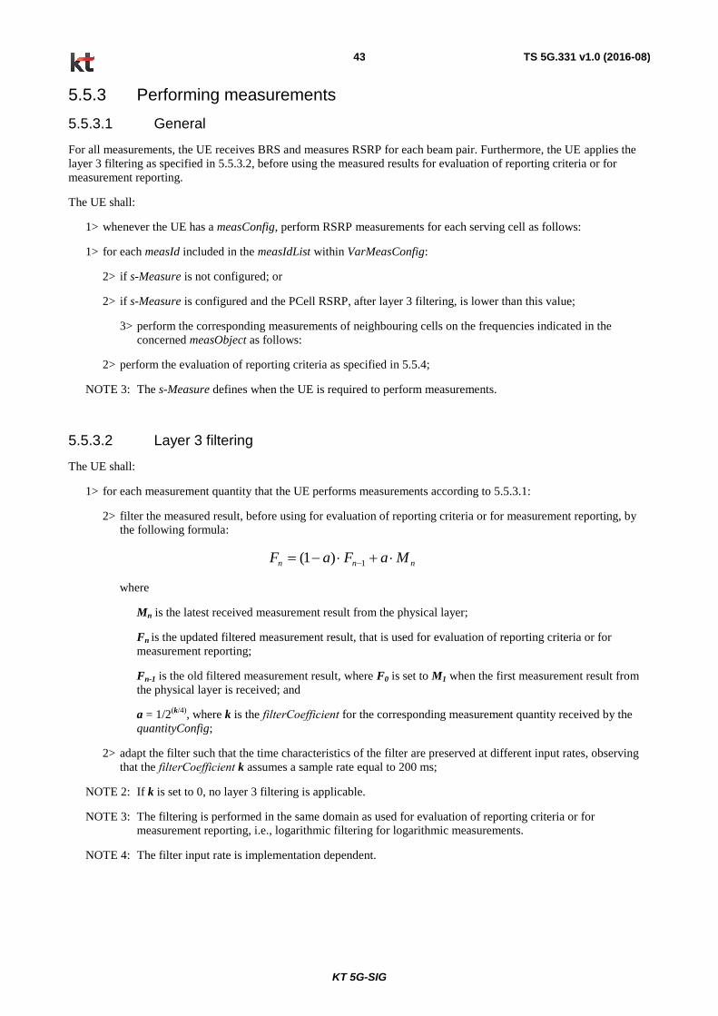
KT 5G-SIG
TS 5G.331 v1.0 (2016-08) 43
5.5.3 Performing measurements
5.5.3.1 General
For all measurements, the UE receives BRS and measures RSRP for each beam pair. Furthermore, the UE applies the
layer 3 filtering as specified in 5.5.3.2, before using the measured results for evaluation of reporting criteria or for
measurement reporting.
The UE shall:
1> whenever the UE has a measConfig, perform RSRP measurements for each serving cell as follows:
1> for each measId included in the measIdList within VarMeasConfig:
2> if s-Measure is not configured; or
2> if s-Measure is configured and the PCell RSRP, after layer 3 filtering, is lower than this value;
3> perform the corresponding measurements of neighbouring cells on the frequencies indicated in the
concerned measObject as follows:
2> perform the evaluation of reporting criteria as specified in 5.5.4;
NOTE 3: The s-Measure defines when the UE is required to perform measurements.
5.5.3.2 Layer 3 filtering
The UE shall:
1> for each measurement quantity that the UE performs measurements according to 5.5.3.1:
2> filter the measured result, before using for evaluation of reporting criteria or for measurement reporting, by
the following formula:
nnn MaFaF 1)1(
where
Mn is the latest received measurement result from the physical layer;
Fn is the updated filtered measurement result, that is used for evaluation of reporting criteria or for
measurement reporting;
Fn-1 is the old filtered measurement result, where F0 is set to M1 when the first measurement result from
the physical layer is received; and
a = 1/2(k/4)
, where k is the filterCoefficient for the corresponding measurement quantity received by the
quantityConfig;
2> adapt the filter such that the time characteristics of the filter are preserved at different input rates, observing
that the filterCoefficient k assumes a sample rate equal to 200 ms;
NOTE 2: If k is set to 0, no layer 3 filtering is applicable.
NOTE 3: The filtering is performed in the same domain as used for evaluation of reporting criteria or for
measurement reporting, i.e., logarithmic filtering for logarithmic measurements.
NOTE 4: The filter input rate is implementation dependent.

KT 5G-SIG
TS 5G.331 v1.0 (2016-08) 44
5.5.4 Measurement report triggering
5.5.4.1 General
If security has been activated successfully, the UE shall:
1> for each measId included in the measIdList within VarMeasConfig:
2> if the eventA1 or eventA2 is configured in the corresponding reportConfig:
3> consider only the serving cell to be applicable;
2> else:
3> consider any neighbouring cell detected on the associated frequency to be applicable;
4> for events involving a serving cell on one frequency and neighbours on another frequency, consider
the serving cell on the other frequency as a neighbouring cell;
2> if the triggerType is set to event and if reportForMobility is set to TRUE for the entry condition applicable
for this event, i.e. the event corresponding with the eventId of the corresponding reportConfig within
VarMeasConfig, is fulfilled for one or more applicable cells for all measurements after layer 3 filtering taken
during timeToTrigger defined for this event within the VarMeasConfig, while the VarMeasReportList does
not include an measurement reporting entry for this measId (a first cell triggers the event):
3> include a measurement reporting entry within the VarMeasReportList for this measId;
3> set the numberOfReportsSent defined within the VarMeasReportList for this measId to 0;
3> include the concerned cell(s) in the cellsTriggeredList defined within the VarMeasReportList for this
measId;
3> if the UE supports T312 and if useT312 is included for this event and if T310 is running:
4> if T312 is not running:
5> start timer T312 with the value configured in the corresponding measObject;
3> initiate the measurement reporting procedure, as specified in 5.5.5;
2> if the triggerType is set to event and if reportForMobility is set to TRUE for this event and if the entry
condition applicable for this event, i.e. the event corresponding with the eventId of the corresponding
reportConfig within VarMeasConfig, is fulfilled for one or more applicable cells not included in the
cellsTriggeredList for all measurements after layer 3 filtering taken during timeToTrigger defined for this
event within the VarMeasConfig (a subsequent cell triggers the event):
3> set the numberOfReportsSent defined within the VarMeasReportList for this measId to 0;
3> include the concerned cell(s) in the cellsTriggeredList defined within the VarMeasReportList for this
measId;
3> if the UE supports T312 and if useT312 is included for this event and if T310 is running:
4> if T312 is not running:
5> start timer T312 with the value configured in the corresponding measObject;
3> initiate the measurement reporting procedure, as specified in 5.5.5;
2> if the triggerType is set to event if reportForMobility is set to TRUE for this event and if the leaving
condition applicable for this event is fulfilled for one or more of the cells included in the cellsTriggeredList
defined within the VarMeasReportList for this measId for all measurements after layer 3 filtering taken
during timeToTrigger defined within the VarMeasConfig for this event:
3> remove the concerned cell(s) in the cellsTriggeredList defined within the VarMeasReportList for this
measId;

KT 5G-SIG
TS 5G.331 v1.0 (2016-08) 45
3> if the UE supports T312 and if useT312 is included for this event and if T310 is running:
4> if T312 is not running:
5> start timer T312 with the value configured in the corresponding measObject;
3> if reportOnLeave is set to TRUE for the corresponding reporting configuration:
4> initiate the measurement reporting procedure, as specified in 5.5.5;
3> if the cellsTriggeredList defined within the VarMeasReportList for this measId is empty:
4> remove the measurement reporting entry within the VarMeasReportList for this measId;
4> stop the periodical reporting timer for this measId, if running;
2> upon expiry of the periodical reporting timer for this measId:
3> initiate the measurement reporting procedure, as specified in 5.5.5;
NOTE 2: The UE does not stop the periodical reporting with triggerType set to event or to periodical while the
corresponding measurement is not performed due to the PCell RSRP being equal to or better than s-
Measure or due to the measurement gap not being setup.
5.5.4.2 Event A1 (Serving 5G cell becomes better than threshold)
The UE shall:
1> consider the entering condition for this event to be satisfied when condition A1-1, as specified below, is fulfilled;
1> consider the leaving condition for this event to be satisfied when condition A1-2, as specified below, is fulfilled;
1> for this measurement, consider the primary or secondary cell that is configured on the frequency indicated in the
associated measObject5GRAN to be the serving cell;
Inequality A1-1 (Entering condition)
ThreshHysMs
Inequality A1-2 (Leaving condition)
ThreshHysMs
The variables in the formula are defined as follows:
Ms is the measurement result of the serving cell, not taking into account any offsets.
Hys is the hysteresis parameter for this event (i.e. hysteresis as defined within reportConfig5GRA for this event).
Thresh is the threshold parameter for this event (i.e. a1-Threshold as defined within reportConfig5GRA for this
event).
Ms is expressed in dBm in case of RSRP.
Hys is expressed in dB.
Thresh is expressed in the same unit as Ms.
5.5.4.3 Event A2 (Serving 5G cell becomes worse than threshold)
The UE shall:
1> consider the entering condition for this event to be satisfied when condition A2-1, as specified below, is fulfilled;
KT 5G-SIG
TS 5G.331 v1.0 (2016-08) 46
1> consider the leaving condition for this event to be satisfied when condition A2-2, as specified below, is fulfilled;
1> for this measurement, consider the primary or secondary cell that is configured on the frequency indicated in the
associated measObject5GRAN to be the serving cell;
Inequality A2-1 (Entering condition)
ThreshHysMs
Inequality A2-2 (Leaving condition)
ThreshHysMs
The variables in the formula are defined as follows:
Ms is the measurement result of the serving cell, not taking into account any offsets.
Hys is the hysteresis parameter for this event (i.e. hysteresis as defined within reportConfig5GRAN for this event).
Thresh is the threshold parameter for this event (i.e. a2-Threshold as defined within reportConfig5GRAN for this
event).
Ms is expressed in dBm in case of RSRP.
Hys is expressed in dB.
Thresh is expressed in the same unit as Ms.
5.5.4.4 Event A3 (Neighbour 5G cell becomes offset better than serving 5G cell)
The UE shall:
1> consider the entering condition for this event to be satisfied when condition A3-1, as specified below, is fulfilled;
1> consider the leaving condition for this event to be satisfied when condition A3-2, as specified below, is fulfilled;
NOTE The cell(s) that triggers the event is on the frequency indicated in the associated measObject which may
be different from the (primary) frequency used by the PCell.
Inequality A3-1 (Entering condition)
OffOcpOfpMpHysOcnOfnMn
Inequality A3-2 (Leaving condition)
OffOcpOfpMpHysOcnOfnMn
The variables in the formula are defined as follows:
Mn is the measurement result of the neighbouring cell, not taking into account any offsets.
Ofn is the frequency specific offset of the frequency of the neighbour cell (i.e. offsetFreq as defined within
measObject5GRAN corresponding to the frequency of the neighbour cell).
Ocn is the cell specific offset of the neighbour cell (i.e. cellIndividualOffset as defined within measObject5GRAN
corresponding to the frequency of the neighbour cell), and set to zero if not configured for the neighbour cell.
Mp is the measurement result of the PCell, not taking into account any offsets.
Ofp is the frequency specific offset of the primary frequency (i.e. offsetFreq as defined within measObject5GRAN
corresponding to the primary frequency).
Ocp is the cell specific offset of the PCell (i.e. cellIndividualOffset as defined within measObject5GRAN
corresponding to the primary frequency), and is set to zero if not configured for the PCell.
Hys is the hysteresis parameter for this event (i.e. hysteresis as defined within reportConfig5GRA for this event).

KT 5G-SIG
TS 5G.331 v1.0 (2016-08) 47
Off is the offset parameter for this event (i.e. a3-Offset as defined within reportConfig5GRA for this event).
Mn, Mp are expressed in dBm in case of RSRP.
Ofn, Ocn, Ofp, Ocp, Hys, Off are expressed in dB.
5.5.4.5 Event A4 Neighbour 5G cell becomes better than threshold.
The UE shall:
1> consider the entering condition for this event to be satisfied when condition A4-1, as specified below, is fulfilled;
1> consider the leaving condition for this event to be satisfied when condition A4-2, as specified below, is fulfilled;
Inequality A4-1 (Entering condition)
ThreshHysOcnOfnMn
Inequality A4-2 (Leaving condition)
ThreshHysOcnOfnMn
The variables in the formula are defined as follows:
Mn is the measurement result of the neighbouring cell, not taking into account any offsets.
Ofn is the frequency specific offset of the frequency of the neighbour cell (i.e. offsetFreq as defined within
measObject5GRAN corresponding to the frequency of the neighbour cell).
Ocn is the cell specific offset of the neighbour cell (i.e. cellIndividualOffset as defined within measObject5GRAN
corresponding to the frequency of the neighbour cell), and set to zero if not configured for the neighbour cell.
Hys is the hysteresis parameter for this event (i.e. hysteresis as defined within reportConfig5GRA for this event).
Thresh is the threshold parameter for this event (i.e. a4-Threshold as defined within reportConfig5GRA for this
event).
Mn is expressed in dBm in case of RSRP.
Ofn, Ocn, Hys are expressed in dB.
Thresh is expressed in the same unit as Mn.
5.5.4.6 Event A5 (PCell becomes worse than threshold1 and neighbour becomes better than threshold2) (for standalone mode)
The UE shall:
1> consider the entering condition for this event to be satisfied when both condition A5-1 and condition A5-2, as
specified below, are fulfilled;
1> consider the leaving condition for this event to be satisfied when condition A5-3 or condition A5-4, i.e. at least
one of the two, as specified below, is fulfilled;
1> use the PCell for Mp;
NOTE: The cell(s) that triggers the event is on the frequency indicated in the associated measObject which may
be different from the frequency used by the PCell.
Inequality A5-1 (Entering condition 1)
1ThreshHysMp
Inequality A5-2 (Entering condition 2)

KT 5G-SIG
TS 5G.331 v1.0 (2016-08) 48
2ThreshHysOcnOfnMn
Inequality A5-3 (Leaving condition 1)
1ThreshHysMp
Inequality A5-4 (Leaving condition 2)
2ThreshHysOcnOfnMn
The variables in the formula are defined as follows:
Mp is the measurement result of the PCell, not taking into account any offsets.
Mn is the measurement result of the neighbouring cell, not taking into account any offsets.
Ofn is the frequency specific offset of the frequency of the neighbour cell (i.e. offsetFreq as defined within
measObject5GRAN corresponding to the frequency of the neighbour cell).
Ocn is the cell specific offset of the neighbour cell (i.e. cellIndividualOffset as defined within measObject5GRAN
corresponding to the frequency of the neighbour cell), and set to zero if not configured for the neighbour cell.
Hys is the hysteresis parameter for this event (i.e. hysteresis as defined within reportConfig5GRA for this event).
Thresh1 is the threshold parameter for this event (i.e. a5-Threshold1 as defined within reportConfig5GRA for this
event).
Thresh2 is the threshold parameter for this event (i.e. a5-Threshold2 as defined within reportConfig5GRA for this
event).
Mn, Mp are expressed in dBm in case of RSRP.
Ofn, Ocn, Hys are expressed in dB.
Thresh1 is expressed in the same unit as Mp.
Thresh2 is expressed in the same unit as Mn.
5.5.5 Measurement reporting
UE 5G-RAN
MeasurementReport
Figure 5.4.5-1: Measurement reporting
The purpose of this procedure is to transfer measurement results from the UE to 5G-RAN. For the ordinary
measurement reporting, 5.5.5.1 section is applied while 5.5.5.2 section is applied for RLF reporting.
5.5.5.1 Measurement reporting triggered by measurement configuration
For the measId for which the measurement reporting procedure was triggered, the UE shall set the measResults within
the MeasurementReport message as follows:
1> set the measId to the measurement identity that triggered the measurement reporting;
1> set the measResultPCell to include the quantities (i.e. RSRP and 5GNB beam ID) of the PCell;
1> set the measResultServFreqList to include for each SCell that is configured, if any, within measResultSCell the
quantities of the concerned SCell, if available;

KT 5G-SIG
TS 5G.331 v1.0 (2016-08) 49
1> if the reportConfig associated with the measId that triggered the measurement reporting includes
reportAddNeighMeas:
2> for each serving frequency for which measObjectId is referenced in the measIdList, other than the frequency
corresponding with the measId that triggered the measurement reporting:
3> set the measResultServFreqList to include within measResultBestNeighCell the physCellId and the
quantities of the best non-serving cell, based on RSRP, on the concerned serving frequency;
1> if there is at least one applicable neighbouring cell to report:
2> set the measResultNeighCells to include the best neighbouring cells up to maxReportCells in accordance with
the following:
3> if the triggerType is set to 'event':
4> include the cells included in the cellsTriggeredList as defined within the VarMeasReportList for this
measId;
3> else:
4> include the applicable cells for which the new measurement results became available since the last
periodical reporting or since the measurement was initiated or reset;
3> for each cell that is included in the measResultNeighCells, include the physCellId;
1> increment the numberOfReportsSent as defined within the VarMeasReportList for this measId by 1;
1> stop the periodical reporting timer, if running;
1> if the numberOfReportsSent as defined within the VarMeasReportList for this measId is less than the
reportAmount as defined within the corresponding reportConfig for this measId:
2> start the periodical reporting timer with the value of reportInterval as defined within the corresponding
reportConfig for this measId;
1> else:
2> if the triggerType is set to 'periodical':
3> remove the entry within the VarMeasReportList for this measId;
3> remove this measId from the measIdList within VarMeasConfig;
1> submit the MeasurementReport message to lower layers for transmission, upon which the procedure ends;
5.5.5.2 Measurement reporting triggered by RLF
The UE shall set the contents of the FailureInformation5G IE in MeausrementReport message as follows:
1> if the UE initiates transmission of the MeasurementReport message to provide 5G radio link failure information:
2> include failureType and set it to the trigger for detecting 5G radio link failure;
1> else if the UE initiates transmission of the MeasurementReport message to provide 5G cell change failure information:
2> include failureType and set it to 5GcellChangeFailure;
1> set the measResultServFreqList to include for each 5G cell that is configured, if any, within measResultSCell the quantities of the concerned SCell, if available

KT 5G-SIG
TS 5G.331 v1.0 (2016-08) 50
1> for each 5G serving frequency included in measResultServFreqList, include within measResultBestNeighCell the physCellId and the quantities of the best non-serving cell, based on RSRP, on the concerned serving frequency;
NOTE 2: The measured quantities are filtered by the L3 filter as configured in the mobility measurement configuration.
The UE shall submit the FailureInformation5G IE in MeasurementReport message to lower layers for transmission.
5.5.6 Measurement related actions
5.5.6.1 Actions upon handover and re-establishment
5G-RAN applies the handover procedure as follows:
- when performing the NW-controlled handover procedure (in case of both non-standalone and standalone modes)
or the UE-based handover procedure (in case of standalone mode), as specified in 5.3.5.4, ensure that a
measObjectId corresponding to the handover target carrier frequency is configured as a result of the procedures
described in this sub-clause and in 5.3.5.4;
- when performing the connection re-establishment procedure, as specified in 5.3.7, ensure that a measObjectId
corresponding to the target carrier frequency is configured as a result of the procedure described in this sub-
clause and the subsequent connection reconfiguration procedure immediately following the re-establishment
procedure;
The UE shall:
1> for each measId included in the measIdList within VarMeasConfig:
2> if the triggerType is set to ‘periodical’:
3> remove this measId from the measIdList within VarMeasConfig:
1> remove all measurement reporting entries within VarMeasReportList;
1> reset the periodical reporting timer, as well as associated information (e.g. timeToTrigger) for all measId.
5.5.6.2 Initiation of UE-based handover to candidate cells (for standalone mode)
If security has been activated successfully, the UE shall:
1> for each measId included in the measIdList within VarMeasConfig:
2> if the triggerType is set to event and if reportForMobility is set to FALSE for this event and if the entry
condition applicable for this event, i.e. the event corresponding with the eventId of the corresponding
reportConfig within VarMeasConfig, is fulfilled for one or more candidate cells configured by 5GNB for all
measurements after layer 3 filtering taken during timeToTrigger defined for this event within the
VarMeasConfig:
3> initiate the RRC connection re-establishment procedure, as specified in 5.3.7;
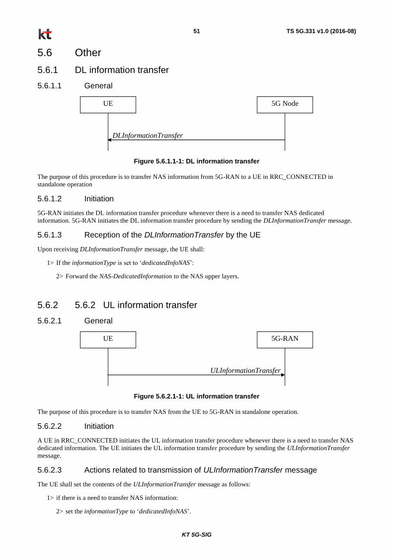
KT 5G-SIG
TS 5G.331 v1.0 (2016-08) 51
5.6 Other
5.6.1 DL information transfer
5.6.1.1 General
DLInformationTransfer
UE 5G Node
Figure 5.6.1.1-1: DL information transfer
The purpose of this procedure is to transfer NAS information from 5G-RAN to a UE in RRC_CONNECTED in
standalone operation
5.6.1.2 Initiation
5G-RAN initiates the DL information transfer procedure whenever there is a need to transfer NAS dedicated
information. 5G-RAN initiates the DL information transfer procedure by sending the DLInformationTransfer message.
5.6.1.3 Reception of the DLInformationTransfer by the UE
Upon receiving DLInformationTransfer message, the UE shall:
1> If the informationType is set to ‘dedicatedInfoNAS’:
2> Forward the NAS-DedicatedInformation to the NAS upper layers.
5.6.2 5.6.2 UL information transfer
5.6.2.1 General
ULInformationTransfer
UE 5G-RAN
Figure 5.6.2.1-1: UL information transfer
The purpose of this procedure is to transfer NAS from the UE to 5G-RAN in standalone operation.
5.6.2.2 Initiation
A UE in RRC_CONNECTED initiates the UL information transfer procedure whenever there is a need to transfer NAS
dedicated information. The UE initiates the UL information transfer procedure by sending the ULInformationTransfer
message.
5.6.2.3 Actions related to transmission of ULInformationTransfer message
The UE shall set the contents of the ULInformationTransfer message as follows:
1> if there is a need to transfer NAS information:
2> set the informationType to ‘dedicatedInfoNAS’.

KT 5G-SIG
TS 5G.331 v1.0 (2016-08) 52
2> include the NAS-DedicatedInformation.
5.6.2.4 Failure to deliver ULInformationTransfer message
The UE shall:
1> if mobility (i.e. handover, RRC connection re-establishment) occurs before the successful delivery of
ULInformationTransfer messages has been confirmed by lower layers:
2> inform upper layers about the possible failure to deliver the information contained in the concerned
ULInformationTransfer messages;
5.6.3 UE capability transfer
5.6.3.1 General
UE 5G-RAN
UECapabilityEnquiry
UECapabilityInformation
Figure 5.5.1-2: UE 5G capability transfer, network initiated
The purpose of this procedure is to transfer UE radio access capability information from the UE to 5G-RAN.
5.6.3.2 Initiation
5G-RAN initiates the procedure after a successful establishment of LTE DRB corresponding to 5G RRC connection or
to a UE in 5G RRC_CONNECTED when it needs (additional) UE radio access capability information.
5.6.3.3 Reception of the 5G UECapabilityEnquiry by the UE
The UE shall:
1> set the contents of UECapabilityInformation message as follows:
2> If the ue-RadioAccessCapRequest includes 5G-RAN:
3> include the UE-5GRA-Capability within a ueCapabilitiesRAT-Container and with the rat-Type set to
‘5gra’;
1> submit the UECapabilityInformation message to lower layers for transmission, upon which the procedure ends.
5.7 Generic error handling
5.7.1 General
The generic error handling defined in the subsequent sub-clauses applies unless explicitly specified otherwise e.g.
within the procedure specific error handling.
The UE shall consider a value as not comprehended when it is set:

KT 5G-SIG
TS 5G.331 v1.0 (2016-08) 53
- to an extended value that is not defined in the version of the transfer syntax supported by the UE.
- to a spare or reserved value unless the specification defines specific behaviour that the UE shall apply upon
receiving the concerned spare/ reserved value.
The UE shall consider a field as not comprehended when it is defined:
- as spare or reserved unless the specification defines specific behaviour that the UE shall apply upon receiving the
concerned spare/ reserved field.
5.7.2 ASN.1 violation or encoding error
The UE shall:
1> when receiving an RRC message on the BCCH, for which the abstract syntax is invalid [13]:
2> ignore the message;
NOTE This section applies in case one or more fields is set to a value, other than a spare, reserved or extended value,
not defined in this version of the transfer syntax. E.g. in the case the UE receives value 12 for a field defined as
INTEGER (1..11). In cases like this, it may not be possible to reliably detect which field is in the error hence the error
handling is at the message level
5.7.3 Not supported protocol extension
The UE shall, when receiving an RRC message on the xBCCH or xCCCH:
1> if the UE does not comprehend the message type or version:
2> ignore the message;
The UE shall, when receiving an RRC message on any logical channel:
1> if the message includes a field that is mandatory to include in the message (e.g. because conditions for mandatory
presence are fulfilled) and that has a value that the UE does not comprehend:
2> if a default value is defined for this field:
3> treat the rest of the message while using the default value defined for this field;
2> else:
3> ignore the message;
1> if the message includes a field that is optional to include in the message (e.g. because conditions for optional
presence are fulfilled) and that has a value that the UE does not comprehend:
2> treat the rest of the message as if the field was absent;
1> if the message includes a protocol extension that the UE does not comprehend:
2> treat the rest of the message as if the extension was absent.
NOTE This section does not apply for the case the received message includes an field that is set to a spare value while
the specification defines the UE behaviour for the case the field is set to a spare value, i.e. this section only concerns
protocol extensions for which no UE behaviour has been specified.
5.7.4 Other errors
The UE shall, when receiving an RRC message on the xBCCH or xCCCH:
1> if the message includes a field that is mandatory to include because conditions for mandatory presence are fulfilled)
and that field is absent:
2> ignore the message.
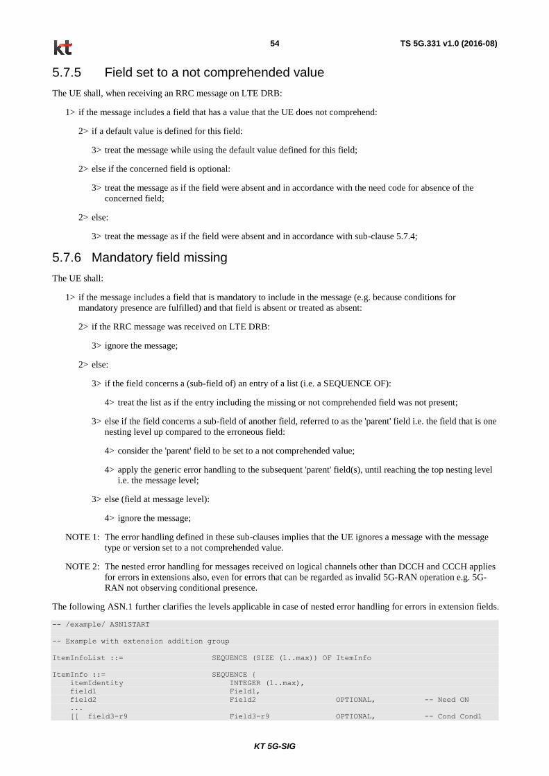
KT 5G-SIG
TS 5G.331 v1.0 (2016-08) 54
5.7.5 Field set to a not comprehended value
The UE shall, when receiving an RRC message on LTE DRB:
1> if the message includes a field that has a value that the UE does not comprehend:
2> if a default value is defined for this field:
3> treat the message while using the default value defined for this field;
2> else if the concerned field is optional:
3> treat the message as if the field were absent and in accordance with the need code for absence of the
concerned field;
2> else:
3> treat the message as if the field were absent and in accordance with sub-clause 5.7.4;
5.7.6 Mandatory field missing
The UE shall:
1> if the message includes a field that is mandatory to include in the message (e.g. because conditions for
mandatory presence are fulfilled) and that field is absent or treated as absent:
2> if the RRC message was received on LTE DRB:
3> ignore the message;
2> else:
3> if the field concerns a (sub-field of) an entry of a list (i.e. a SEQUENCE OF):
4> treat the list as if the entry including the missing or not comprehended field was not present;
3> else if the field concerns a sub-field of another field, referred to as the 'parent' field i.e. the field that is one
nesting level up compared to the erroneous field:
4> consider the 'parent' field to be set to a not comprehended value;
4> apply the generic error handling to the subsequent 'parent' field(s), until reaching the top nesting level
i.e. the message level;
3> else (field at message level):
4> ignore the message;
NOTE 1: The error handling defined in these sub-clauses implies that the UE ignores a message with the message
type or version set to a not comprehended value.
NOTE 2: The nested error handling for messages received on logical channels other than DCCH and CCCH applies
for errors in extensions also, even for errors that can be regarded as invalid 5G-RAN operation e.g. 5G-
RAN not observing conditional presence.
The following ASN.1 further clarifies the levels applicable in case of nested error handling for errors in extension fields.
-- /example/ ASN1START
-- Example with extension addition group
ItemInfoList ::= SEQUENCE (SIZE (1..max)) OF ItemInfo
ItemInfo ::= SEQUENCE {
itemIdentity INTEGER (1..max),
field1 Field1,
field2 Field2 OPTIONAL, -- Need ON
...
[[ field3-r9 Field3-r9 OPTIONAL, -- Cond Cond1
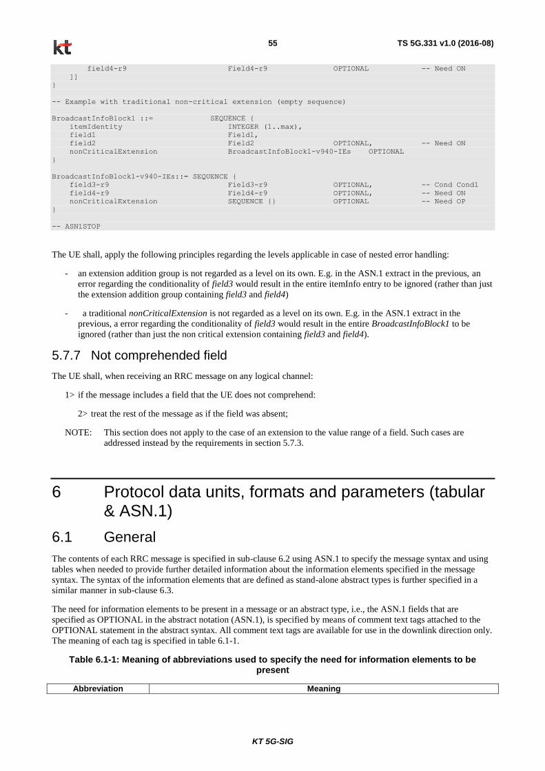
KT 5G-SIG
TS 5G.331 v1.0 (2016-08) 55
field4-r9 Field4-r9 OPTIONAL -- Need ON
]]
}
-- Example with traditional non-critical extension (empty sequence)
BroadcastInfoBlock1 ::= SEQUENCE {
itemIdentity INTEGER (1..max),
field1 Field1,
field2 Field2 OPTIONAL, -- Need ON
nonCriticalExtension BroadcastInfoBlock1-v940-IEs OPTIONAL
}
BroadcastInfoBlock1-v940-IEs::= SEQUENCE {
field3-r9 Field3-r9 OPTIONAL, -- Cond Cond1
field4-r9 Field4-r9 OPTIONAL, -- Need ON
nonCriticalExtension SEQUENCE {} OPTIONAL -- Need OP
}
-- ASN1STOP
The UE shall, apply the following principles regarding the levels applicable in case of nested error handling:
- an extension addition group is not regarded as a level on its own. E.g. in the ASN.1 extract in the previous, an
error regarding the conditionality of field3 would result in the entire itemInfo entry to be ignored (rather than just
the extension addition group containing field3 and field4)
- a traditional nonCriticalExtension is not regarded as a level on its own. E.g. in the ASN.1 extract in the
previous, a error regarding the conditionality of field3 would result in the entire BroadcastInfoBlock1 to be
ignored (rather than just the non critical extension containing field3 and field4).
5.7.7 Not comprehended field
The UE shall, when receiving an RRC message on any logical channel:
1> if the message includes a field that the UE does not comprehend:
2> treat the rest of the message as if the field was absent;
NOTE: This section does not apply to the case of an extension to the value range of a field. Such cases are
addressed instead by the requirements in section 5.7.3.
6 Protocol data units, formats and parameters (tabular & ASN.1)
6.1 General
The contents of each RRC message is specified in sub-clause 6.2 using ASN.1 to specify the message syntax and using
tables when needed to provide further detailed information about the information elements specified in the message
syntax. The syntax of the information elements that are defined as stand-alone abstract types is further specified in a
similar manner in sub-clause 6.3.
The need for information elements to be present in a message or an abstract type, i.e., the ASN.1 fields that are
specified as OPTIONAL in the abstract notation (ASN.1), is specified by means of comment text tags attached to the
OPTIONAL statement in the abstract syntax. All comment text tags are available for use in the downlink direction only.
The meaning of each tag is specified in table 6.1-1.
Table 6.1-1: Meaning of abbreviations used to specify the need for information elements to be present
Abbreviation Meaning
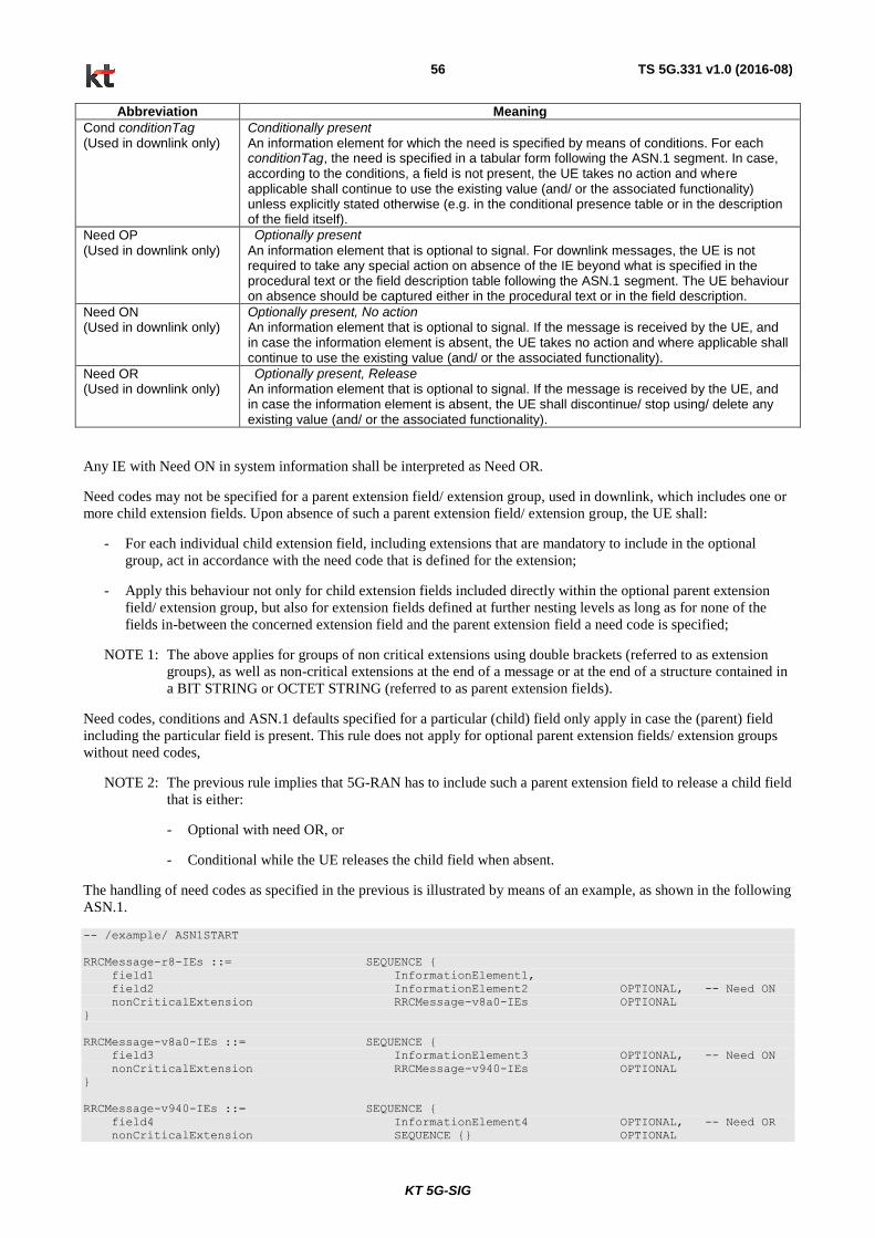
KT 5G-SIG
TS 5G.331 v1.0 (2016-08) 56
Abbreviation Meaning
Cond conditionTag (Used in downlink only)
Conditionally present An information element for which the need is specified by means of conditions. For each conditionTag, the need is specified in a tabular form following the ASN.1 segment. In case, according to the conditions, a field is not present, the UE takes no action and where applicable shall continue to use the existing value (and/ or the associated functionality) unless explicitly stated otherwise (e.g. in the conditional presence table or in the description of the field itself).
Need OP (Used in downlink only)
Optionally present
An information element that is optional to signal. For downlink messages, the UE is not required to take any special action on absence of the IE beyond what is specified in the procedural text or the field description table following the ASN.1 segment. The UE behaviour on absence should be captured either in the procedural text or in the field description.
Need ON (Used in downlink only)
Optionally present, No action An information element that is optional to signal. If the message is received by the UE, and in case the information element is absent, the UE takes no action and where applicable shall continue to use the existing value (and/ or the associated functionality).
Need OR (Used in downlink only)
Optionally present, Release An information element that is optional to signal. If the message is received by the UE, and in case the information element is absent, the UE shall discontinue/ stop using/ delete any existing value (and/ or the associated functionality).
Any IE with Need ON in system information shall be interpreted as Need OR.
Need codes may not be specified for a parent extension field/ extension group, used in downlink, which includes one or
more child extension fields. Upon absence of such a parent extension field/ extension group, the UE shall:
- For each individual child extension field, including extensions that are mandatory to include in the optional
group, act in accordance with the need code that is defined for the extension;
- Apply this behaviour not only for child extension fields included directly within the optional parent extension
field/ extension group, but also for extension fields defined at further nesting levels as long as for none of the
fields in-between the concerned extension field and the parent extension field a need code is specified;
NOTE 1: The above applies for groups of non critical extensions using double brackets (referred to as extension
groups), as well as non-critical extensions at the end of a message or at the end of a structure contained in
a BIT STRING or OCTET STRING (referred to as parent extension fields).
Need codes, conditions and ASN.1 defaults specified for a particular (child) field only apply in case the (parent) field
including the particular field is present. This rule does not apply for optional parent extension fields/ extension groups
without need codes,
NOTE 2: The previous rule implies that 5G-RAN has to include such a parent extension field to release a child field
that is either:
- Optional with need OR, or
- Conditional while the UE releases the child field when absent.
The handling of need codes as specified in the previous is illustrated by means of an example, as shown in the following
ASN.1.
-- /example/ ASN1START
RRCMessage-r8-IEs ::= SEQUENCE {
field1 InformationElement1,
field2 InformationElement2 OPTIONAL, -- Need ON
nonCriticalExtension RRCMessage-v8a0-IEs OPTIONAL
}
RRCMessage-v8a0-IEs ::= SEQUENCE {
field3 InformationElement3 OPTIONAL, -- Need ON
nonCriticalExtension RRCMessage-v940-IEs OPTIONAL
}
RRCMessage-v940-IEs ::= SEQUENCE {
field4 InformationElement4 OPTIONAL, -- Need OR
nonCriticalExtension SEQUENCE {} OPTIONAL
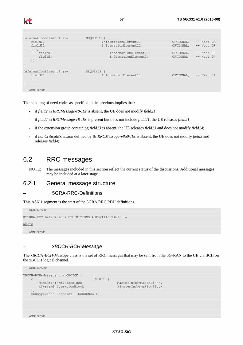
KT 5G-SIG
TS 5G.331 v1.0 (2016-08) 57
}
InformationElement1 ::= SEQUENCE {
field11 InformationElement11 OPTIONAL, -- Need ON
field12 InformationElement12 OPTIONAL, -- Need OR
...,
[[ field13 InformationElement13 OPTIONAL, -- Need OR
field14 InformationElement14 OPTIONAL -- Need ON
]]
}
InformationElement2 ::= SEQUENCE {
field21 InformationElement11 OPTIONAL, -- Need OR
...
}
-- ASN1STOP
The handling of need codes as specified in the previous implies that:
- if field2 in RRCMessage-r8-IEs is absent, the UE does not modify field21;
- if field2 in RRCMessage-r8-IEs is present but does not include field21, the UE releases field21;
- if the extension group containing field13 is absent, the UE releases field13 and does not modify field14;
- if nonCriticalExtension defined by IE RRCMessage-v8a0-IEs is absent, the UE does not modify field3 and
releases field4;
6.2 RRC messages
NOTE: The messages included in this section reflect the current status of the discussions. Additional messages
may be included at a later stage.
6.2.1 General message structure
– 5GRA-RRC-Definitions
This ASN.1 segment is the start of the 5GRA RRC PDU definitions.
-- ASN1START
KT5GRA-RRC-Definitions DEFINITIONS AUTOMATIC TAGS ::=
BEGIN
-- ASN1STOP
– xBCCH-BCH-Message
The xBCCH-BCH-Message class is the set of RRC messages that may be sent from the 5G-RAN to the UE via BCH on
the xBCCH logical channel.
-- ASN1START
XBCCH-BCH-Message ::= CHOICE {
c1 CHOICE {
masterInformationBlock MasterInformationBlock,
xSystemInformationBlock XSystemInformationBlock
},
messageClassExtension SEQUENCE {}
}
-- ASN1STOP
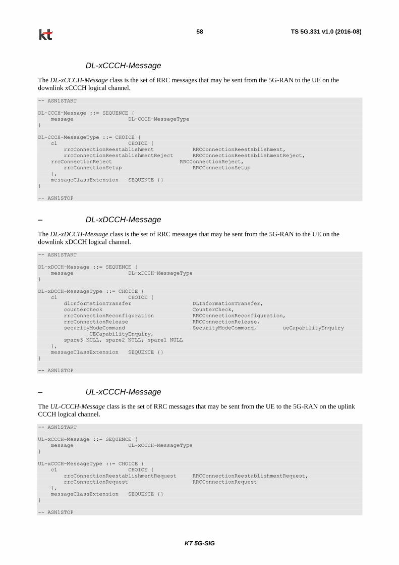
KT 5G-SIG
TS 5G.331 v1.0 (2016-08) 58
DL-xCCCH-Message
The DL-xCCCH-Message class is the set of RRC messages that may be sent from the 5G-RAN to the UE on the
downlink xCCCH logical channel.
-- ASN1START
DL-CCCH-Message ::= SEQUENCE {
message DL-CCCH-MessageType
}
DL-CCCH-MessageType ::= CHOICE {
c1 CHOICE {
rrcConnectionReestablishment RRCConnectionReestablishment,
rrcConnectionReestablishmentReject RRCConnectionReestablishmentReject,
rrcConnectionReject RRCConnectionReject,
rrcConnectionSetup RRCConnectionSetup
},
messageClassExtension SEQUENCE {}
}
-- ASN1STOP
– DL-xDCCH-Message
The DL-xDCCH-Message class is the set of RRC messages that may be sent from the 5G-RAN to the UE on the
downlink xDCCH logical channel.
-- ASN1START
DL-xDCCH-Message ::= SEQUENCE {
message DL-xDCCH-MessageType
}
DL-xDCCH-MessageType ::= CHOICE {
c1 CHOICE {
dlInformationTransfer DLInformationTransfer,
counterCheck CounterCheck,
rrcConnectionReconfiguration RRCConnectionReconfiguration,
rrcConnectionRelease RRCConnectionRelease,
securityModeCommand SecurityModeCommand, ueCapabilityEnquiry
UECapabilityEnquiry,
spare3 NULL, spare2 NULL, spare1 NULL
},
messageClassExtension SEQUENCE {}
}
-- ASN1STOP
– UL-xCCCH-Message
The UL-CCCH-Message class is the set of RRC messages that may be sent from the UE to the 5G-RAN on the uplink
CCCH logical channel.
-- ASN1START
UL-xCCCH-Message ::= SEQUENCE {
message UL-xCCCH-MessageType
}
UL-xCCCH-MessageType ::= CHOICE {
c1 CHOICE {
rrcConnectionReestablishmentRequest RRCConnectionReestablishmentRequest,
rrcConnectionRequest RRCConnectionRequest
},
messageClassExtension SEQUENCE {}
}
-- ASN1STOP
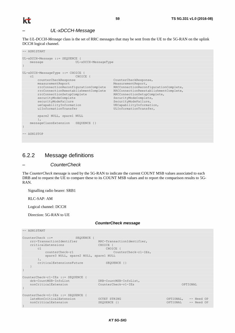
KT 5G-SIG
TS 5G.331 v1.0 (2016-08) 59
– UL-xDCCH-Message
The UL-DCCH-Message class is the set of RRC messages that may be sent from the UE to the 5G-RAN on the uplink
DCCH logical channel.
-- ASN1START
UL-xDCCH-Message ::= SEQUENCE {
message UL-xDCCH-MessageType
}
UL-xDCCH-MessageType ::= CHOICE {
c1 CHOICE {
counterCheckResponse CounterCheckResponse,
measurementReport MeasurementReport,
rrcConnectionReconfigurationComplete RRCConnectionReconfigurationComplete,
rrcConnectionReestablishmentComplete RRCConnectionReestablishmentComplete,
rrcConnectionSetupComplete RRCConnectionSetupComplete,
securityModeComplete SecurityModeComplete,
securityModeFailure SecurityModeFailure,
ueCapabilityInformation UECapabilityInformation,
ulInformationTransfer ULInformationTransfer,
spare2 NULL, spare1 NULL
},
messageClassExtension SEQUENCE {}
}
-- ASN1STOP
6.2.2 Message definitions
– CounterCheck
The CounterCheck message is used by the 5G-RAN to indicate the current COUNT MSB values associated to each
DRB and to request the UE to compare these to its COUNT MSB values and to report the comparison results to 5G-
RAN.
Signalling radio bearer: SRB1
RLC-SAP: AM
Logical channel: DCCH
Direction: 5G-RAN to UE
CounterCheck message
-- ASN1START
CounterCheck ::= SEQUENCE {
rrc-TransactionIdentifier RRC-TransactionIdentifier,
criticalExtensions CHOICE {
c1 CHOICE {
counterCheck-r1 CounterCheck-r1-IEs,
spare3 NULL, spare2 NULL, spare1 NULL
},
criticalExtensionsFuture SEQUENCE {}
}
}
CounterCheck-r1-IEs ::= SEQUENCE {
drb-CountMSB-InfoList DRB-CountMSB-InfoList,
nonCriticalExtension CounterCheck-v1-IEs OPTIONAL
}
CounterCheck-v1-IEs ::= SEQUENCE {
lateNonCriticalExtension OCTET STRING OPTIONAL, -- Need OP
nonCriticalExtension SEQUENCE {} OPTIONAL -- Need OP
}

KT 5G-SIG
TS 5G.331 v1.0 (2016-08) 60
DRB-CountMSB-InfoList ::= SEQUENCE (SIZE (1..maxDRB)) OF DRB-CountMSB-Info
DRB-CountMSB-Info ::= SEQUENCE {
drb-Identity DRB-Identity,
countMSB-Uplink INTEGER(0..33554431),
countMSB-Downlink INTEGER(0..33554431)
}
-- ASN1STOP
CounterCheck field descriptions
drb-CountMSB-InfoList Indicates the MSBs of the COUNT values of the DRBs.
count-MSB-Uplink
Indicates the value of 25 MSBs from uplink COUNT associated to this DRB.
count-MSB-Downlink Indicates the value of 25 MSBs from downlink COUNT associated to this DRB.
– CounterCheckResponse
The CounterCheckResponse message is used by the UE to respond to a CounterCheck message.
Signalling radio bearer: SRB1
RLC-SAP: AM
Logical channel: xDCCH
Direction: UE to 5G-RAN
CounterCheckResponse message
-- ASN1START
CounterCheckResponse ::= SEQUENCE {
rrc-TransactionIdentifier RRC-TransactionIdentifier,
criticalExtensions CHOICE {
counterCheckResponse-r1 CounterCheckResponse-r1-IEs,
criticalExtensionsFuture SEQUENCE {}
}
}
CounterCheckResponse-r1-IEs ::= SEQUENCE {
drb-CountInfoList DRB-CountInfoList,
nonCriticalExtension CounterCheckResponse-v1-IEs OPTIONAL
}
CounterCheckResponse-v1-IEs ::= SEQUENCE {
lateNonCriticalExtension OCTET STRING OPTIONAL,
nonCriticalExtension SEQUENCE {} OPTIONAL
}
DRB-CountInfoList ::= SEQUENCE (SIZE (0..maxDRB)) OF DRB-CountInfo
DRB-CountInfo ::= SEQUENCE {
drb-Identity DRB-Identity,
count-Uplink INTEGER(0..4294967295),
count-Downlink INTEGER(0..4294967295)
}
-- ASN1STOP

KT 5G-SIG
TS 5G.331 v1.0 (2016-08) 61
CounterCheckResponse field descriptions
drb-CountInfoList Indicates the COUNT values of the DRBs.
count-Uplink Indicates the value of uplink COUNT associated to this DRB.
count-Downlink Indicates the value of downlink COUNT associated to this DRB.
– DLInformationTransfer
The DLInformationTransfer message is used for the downlink transfer of dedicated NAS information.
Signalling radio bearer: SRB2 or SRB1 (only if SRB2 not established yet. If SRB2 is suspended, 5G-RAN does not
send this message until SRB2 is resumed.)
RLC-SAP: AM
Logical channel: xDCCH
Direction: 5G-RAN to UE
DLInformationTransfer message
-- ASN1START
DLInformationTransfer ::= SEQUENCE {
rrc-TransactionIdentifier RRC-TransactionIdentifier,
criticalExtensions CHOICE {
c1 CHOICE {
dlInformationTransfer-r1 DLInformationTransfer-r1-IEs,
spare3 NULL, spare2 NULL, spare1 NULL
},
criticalExtensionsFuture SEQUENCE {}
}
}
DLInformationTransfer-r1-IEs ::= SEQUENCE {
informationType CHOICE {
dedicatedInfoNAS DedicatedInfoNAS,
spare3 NULL, spare2 NULL, spare1 NULL
},
nonCriticalExtension DLInformationTransfer-v1-IEs OPTIONAL
}
DLInformationTransfer-v1-IEs ::= SEQUENCE {
lateNonCriticalExtension OCTET STRING OPTIONAL, -- Need OP
nonCriticalExtension SEQUENCE {} OPTIONAL -- Need OP
}
-- ASN1STOP
– MasterInformationBlock
The MasterInformationBlock includes the system information transmitted on xBCH.
Signalling radio bearer: N/A
RLC-SAP: TM
Logical channel: xBCCH
Direction: 5G-RAN to UE
MasterInformationBlock
-- ASN1START
MasterInformationBlock ::= SEQUENCE {
systemFrameNumber BIT STRING (SIZE (8)),

KT 5G-SIG
TS 5G.331 v1.0 (2016-08) 62
brsTransmissionPeriod ENUMERATED {mx5, ms5, ms10, ms20},
ePBCHConfiguration ENUMERATED {config0, config1, spare0, spare1},
spare BIT STRING (SIZE (4))
}
-- ASN1STOP
MasterInformationBlock field descriptions
systemFrameNumber
Defines the SFN. brsTrasnmissionPeriod Defines the transmission period of Beam Reference Signal. Value in number of milliseconds. Value mx5 corresponds 5ms repetition when half subframe is used for xPBCH and BRS transmission. ms5, ms10, ms20 corresponds 5ms 10ms, and 20 ms periodicity when complete subframes are used for BRS transmission.
ePBCHConfiguration Defines the transmission of ePBCH. It is FFS, whether only precesense is signalled or different periodicities.
Other paramters to MIB are FFS
– MeasurementReport (for standalone)
The MeasurementReport message is used for the indication of measurement results.
Signalling radio bearer: SRB1
RLC-SAP: AM
Logical channel: xDCCH
Direction: UE to 5G-RAN
MeasurementReport message
-- ASN1START
MeasurementReport ::= SEQUENCE {
criticalExtensions CHOICE {
c1 CHOICE{
measurementReport-r1 MeasurementReport-r1-IEs,
spare7 NULL,
spare6 NULL, spare5 NULL, spare4 NULL,
spare3 NULL, spare2 NULL, spare1 NULL
},
criticalExtensionsFuture SEQUENCE {}
}
}
MeasurementReport-r1-IEs ::= SEQUENCE {
measResults MeasResults,
nonCriticalExtension MeasurementReport-v1-IEs OPTIONAL
}
MeasurementReport-v1-IEs ::= SEQUENCE {
lateNonCriticalExtension OCTET STRING OPTIONAL,
nonCriticalExtension SEQUENCE {} OPTIONAL
}
-- ASN1STOP
– MeasurementReport (for non-standalone)
The MeasurementReport message is used for the indication of measurement results and RLF.
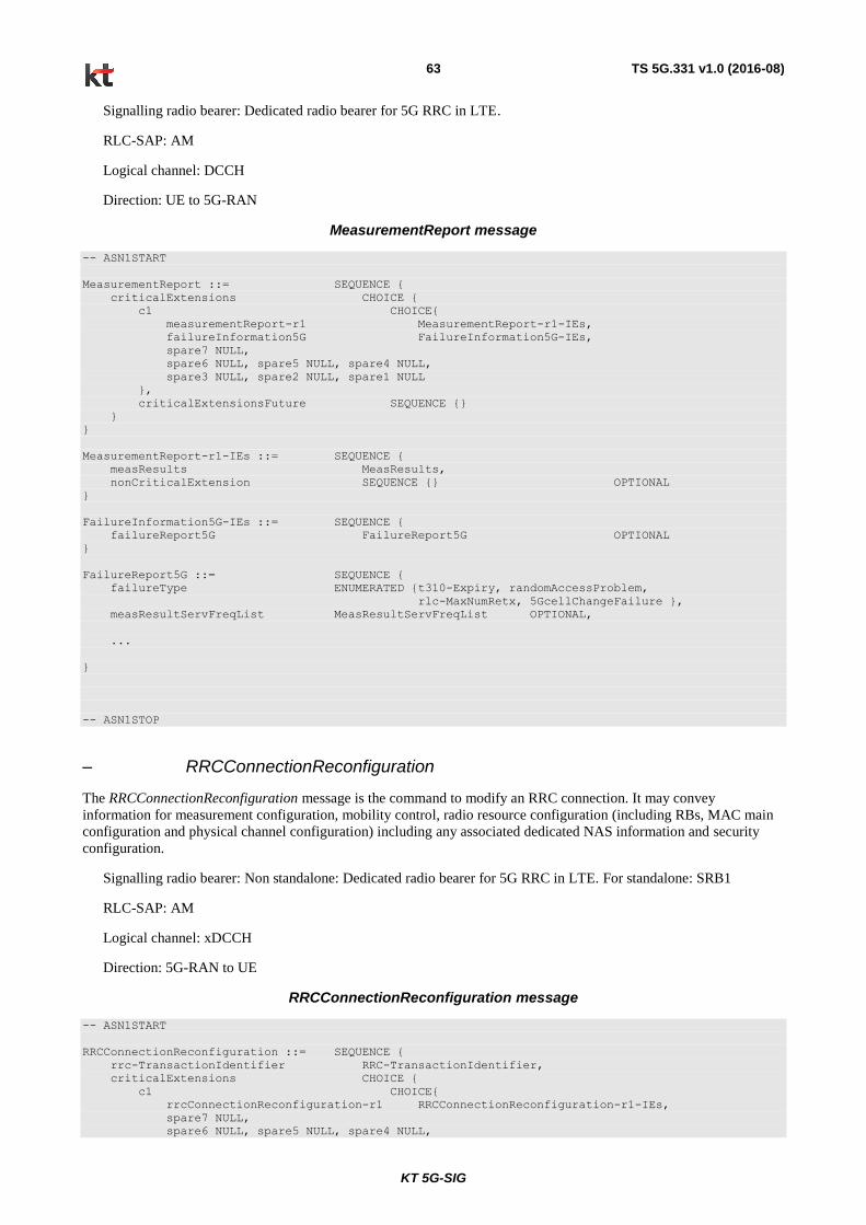
KT 5G-SIG
TS 5G.331 v1.0 (2016-08) 63
Signalling radio bearer: Dedicated radio bearer for 5G RRC in LTE.
RLC-SAP: AM
Logical channel: DCCH
Direction: UE to 5G-RAN
MeasurementReport message
-- ASN1START
MeasurementReport ::= SEQUENCE {
criticalExtensions CHOICE {
c1 CHOICE{
measurementReport-r1 MeasurementReport-r1-IEs,
failureInformation5G FailureInformation5G-IEs,
spare7 NULL,
spare6 NULL, spare5 NULL, spare4 NULL,
spare3 NULL, spare2 NULL, spare1 NULL
},
criticalExtensionsFuture SEQUENCE {}
}
}
MeasurementReport-r1-IEs ::= SEQUENCE {
measResults MeasResults,
nonCriticalExtension SEQUENCE {} OPTIONAL
}
FailureInformation5G-IEs ::= SEQUENCE {
failureReport5G FailureReport5G OPTIONAL
}
FailureReport5G ::= SEQUENCE {
failureType ENUMERATED {t310-Expiry, randomAccessProblem,
rlc-MaxNumRetx, 5GcellChangeFailure },
measResultServFreqList MeasResultServFreqList OPTIONAL,
...
}
-- ASN1STOP
– RRCConnectionReconfiguration
The RRCConnectionReconfiguration message is the command to modify an RRC connection. It may convey
information for measurement configuration, mobility control, radio resource configuration (including RBs, MAC main
configuration and physical channel configuration) including any associated dedicated NAS information and security
configuration.
Signalling radio bearer: Non standalone: Dedicated radio bearer for 5G RRC in LTE. For standalone: SRB1
RLC-SAP: AM
Logical channel: xDCCH
Direction: 5G-RAN to UE
RRCConnectionReconfiguration message
-- ASN1START
RRCConnectionReconfiguration ::= SEQUENCE {
rrc-TransactionIdentifier RRC-TransactionIdentifier,
criticalExtensions CHOICE {
c1 CHOICE{
rrcConnectionReconfiguration-r1 RRCConnectionReconfiguration-r1-IEs,
spare7 NULL,
spare6 NULL, spare5 NULL, spare4 NULL,
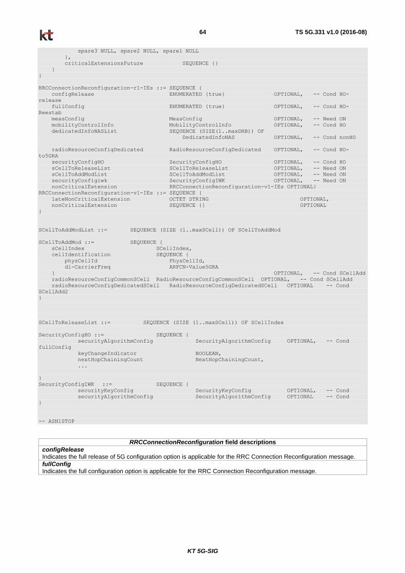
KT 5G-SIG
TS 5G.331 v1.0 (2016-08) 64
spare3 NULL, spare2 NULL, spare1 NULL
},
criticalExtensionsFuture SEQUENCE {}
}
}
RRCConnectionReconfiguration-r1-IEs ::= SEQUENCE {
configRelease ENUMERATED {true} OPTIONAL, -- Cond HO-
release
fullConfig ENUMERATED {true} OPTIONAL, -- Cond HO-
Reestab
measConfig MeasConfig OPTIONAL, -- Need ON
mobilityControlInfo MobilityControlInfo OPTIONAL, -- Cond HO
dedicatedInfoNASList SEQUENCE (SIZE(1..maxDRB)) OF
DedicatedInfoNAS OPTIONAL, -- Cond nonHO
radioResourceConfigDedicated RadioResourceConfigDedicated OPTIONAL, -- Cond HO-
to5GRA
securityConfigHO SecurityConfigHO OPTIONAL, -- Cond HO
sCellToReleaseList SCellToReleaseList OPTIONAL, -- Need ON
sCellToAddModList SCellToAddModList OPTIONAL, -- Need ON
securityConfigiwk SecurityConfigIWK OPTIONAL, -- Need ON
nonCriticalExtension RRCConnectionReconfiguration-v1-IEs OPTIONAL}
RRCConnectionReconfiguration-v1-IEs ::= SEQUENCE {
lateNonCriticalExtension OCTET STRING OPTIONAL,
nonCriticalExtension SEQUENCE {} OPTIONAL
}
SCellToAddModList ::= SEQUENCE (SIZE (1..maxSCell)) OF SCellToAddMod
SCellToAddMod ::= SEQUENCE {
sCellIndex SCellIndex,
cellIdentification SEQUENCE {
physCellId PhysCellId,
dl-CarrierFreq ARFCN-Value5GRA
} OPTIONAL, -- Cond SCellAdd
radioResourceConfigCommonSCell RadioResourceConfigCommonSCell OPTIONAL, -- Cond SCellAdd
radioResourceConfigDedicatedSCell RadioResourceConfigDedicatedSCell OPTIONAL -- Cond
SCellAdd2
}
SCellToReleaseList ::= SEQUENCE (SIZE (1..maxSCell)) OF SCellIndex
SecurityConfigHO ::= SEQUENCE {
securityAlgorithmConfig SecurityAlgorithmConfig OPTIONAL, -- Cond
fullConfig
keyChangeIndicator BOOLEAN,
nextHopChainingCount NextHopChainingCount,
...
}
SecurityConfigIWK ::= SEQUENCE {
securityKeyConfig SecurityKeyConfig OPTIONAL, -- Cond
securityAlgorithmConfig SecurityAlgorithmConfig OPTIONAL -- Cond
}
-- ASN1STOP
RRCConnectionReconfiguration field descriptions
configRelease Indicates the full release of 5G configuration option is applicable for the RRC Connection Reconfiguration message.
fullConfig Indicates the full configuration option is applicable for the RRC Connection Reconfiguration message.

KT 5G-SIG
TS 5G.331 v1.0 (2016-08) 65
Conditional presence Explanation
fullConfig This field is mandatory present for handover within 5G-RA when the fullConfig is included; otherwise it is optionally present, Need OP.
HO The field is mandatory present in case of handover within 5G-RA or to 5G-RA; otherwise the field is not present.
HO-Reestab This field is optionally present, need ON, in case of handover within 5G-RA or upon the first reconfiguration after RRC connection re-establishment; otherwise the field is not present.
HO-to5GRA The field is mandatory present in case of handover to 5G-RA or for reconfigurations when fullConfig is included; otherwise the field is optionally present, need ON.
nonFullConfig The field is not present in case of handover within 5G-RA when the fullConfig is included
or in case of handover to 5G-RA; otherwise it is optional present, need ON.
nonHO The field is not present in case of handover within 5G-RA or to 5G-RA; otherwise it is optional present, need ON.
SCellAdd The field is mandatory present upon SCell addition; otherwise it is not present.
SCellAdd2 The field is mandatory present upon SCell addition; otherwise it is optionally present, need ON.
– RRCConnectionReconfigurationComplete
The RRCConnectionReconfigurationComplete message is used to confirm the successful completion of an RRC
connection reconfiguration.
Signalling radio bearer: Non standalone:Dedicated radio bearer for 5G RRC in LTE. Standalone:SRB1
RLC-SAP: AM
Logical channel: xDCCH
Direction: UE to 5G-RAN
RRCConnectionReconfigurationComplete message
-- ASN1START
RRCConnectionReconfigurationComplete ::= SEQUENCE {
rrc-TransactionIdentifier RRC-TransactionIdentifier,
criticalExtensions CHOICE {
rrcConnectionReconfigurationComplete-r1
RRCConnectionReconfigurationComplete-r1-IEs,
criticalExtensionsFuture SEQUENCE {}
}
}
RRCConnectionReconfigurationComplete-r1-IEs ::= SEQUENCE {
nonCriticalExtension RRCConnectionReconfigurationComplete-v1-IEs OPTIONAL
}
RRCConnectionReconfigurationComplete-v1-IEs ::= SEQUENCE {
lateNonCriticalExtension OCTET STRING OPTIONAL,
nonCriticalExtension SEQUENCE {} OPTIONAL
}
-- ASN1STOP
– RRCConnectionReestablishment
The RRCConnectionReestablishment message is used to re-establish SRB1.

KT 5G-SIG
TS 5G.331 v1.0 (2016-08) 66
Signalling radio bearer: SRB0
RLC-SAP: TM
Logical channel: xCCCH
Direction: 5G-RAN to UE
RRCConnectionReestablishment message
-- ASN1START
RRCConnectionReestablishment ::= SEQUENCE {
rrc-TransactionIdentifier RRC-TransactionIdentifier,
criticalExtensions CHOICE {
c1 CHOICE{
rrcConnectionReestablishment-r1 RRCConnectionReestablishment-r1-IEs,
spare7 NULL,
spare6 NULL, spare5 NULL, spare4 NULL,
spare3 NULL, spare2 NULL, spare1 NULL
},
criticalExtensionsFuture SEQUENCE {}
}
}
RRCConnectionReestablishment-r1-IEs ::= SEQUENCE {
radioResourceConfigDedicated RadioResourceConfigDedicated,
nextHopChainingCount NextHopChainingCount,
nonCriticalExtension RRCConnectionReestablishment-v1-IEs OPTIONAL
}
RRCConnectionReestablishment-v1-IEs ::= SEQUENCE {
lateNonCriticalExtension OCTET STRING OPTIONAL,
nonCriticalExtension SEQUENCE {} OPTIONAL
}
-- ASN1STOP
– RRCConnectionReestablishmentComplete
The RRCConnectionReestablishmentComplete message is used to confirm the successful completion of an RRC
connection reestablishment.
Signalling radio bearer: SRB1
RLC-SAP: AM
Logical channel: xDCCH
Direction: UE to 5G-RAN
RRCConnectionReestablishmentComplete message
-- ASN1START
RRCConnectionReestablishmentComplete ::= SEQUENCE {
rrc-TransactionIdentifier RRC-TransactionIdentifier,
criticalExtensions CHOICE {
rrcConnectionReestablishmentComplete-r1
RRCConnectionReestablishmentComplete-r1-IEs,
criticalExtensionsFuture SEQUENCE {}
}
}
RRCConnectionReestablishmentComplete-r1-IEs ::= SEQUENCE {
nonCriticalExtension RRCConnectionReestablishmentComplete-v1-IEs OPTIONAL
}
RRCConnectionReestablishmentComplete-v1-IEs ::= SEQUENCE {
lateNonCriticalExtension OCTET STRING OPTIONAL,
nonCriticalExtension SEQUENCE {} OPTIONAL
}
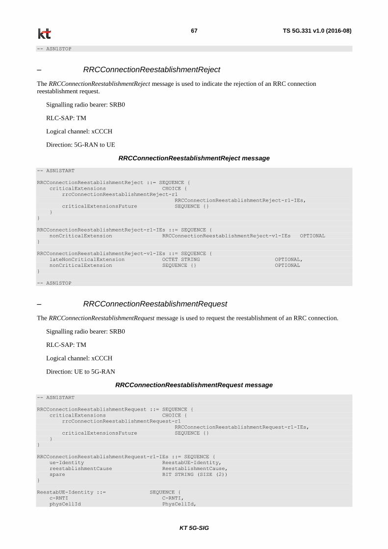
KT 5G-SIG
TS 5G.331 v1.0 (2016-08) 67
-- ASN1STOP
– RRCConnectionReestablishmentReject
The RRCConnectionReestablishmentReject message is used to indicate the rejection of an RRC connection
reestablishment request.
Signalling radio bearer: SRB0
RLC-SAP: TM
Logical channel: xCCCH
Direction: 5G-RAN to UE
RRCConnectionReestablishmentReject message
-- ASN1START
RRCConnectionReestablishmentReject ::= SEQUENCE {
criticalExtensions CHOICE {
rrcConnectionReestablishmentReject-r1
RRCConnectionReestablishmentReject-r1-IEs,
criticalExtensionsFuture SEQUENCE {}
}
}
RRCConnectionReestablishmentReject-r1-IEs ::= SEQUENCE {
nonCriticalExtension RRCConnectionReestablishmentReject-v1-IEs OPTIONAL
}
RRCConnectionReestablishmentReject-v1-IEs ::= SEQUENCE {
lateNonCriticalExtension OCTET STRING OPTIONAL,
nonCriticalExtension SEQUENCE {} OPTIONAL
}
-- ASN1STOP
– RRCConnectionReestablishmentRequest
The RRCConnectionReestablishmentRequest message is used to request the reestablishment of an RRC connection.
Signalling radio bearer: SRB0
RLC-SAP: TM
Logical channel: xCCCH
Direction: UE to 5G-RAN
RRCConnectionReestablishmentRequest message
-- ASN1START
RRCConnectionReestablishmentRequest ::= SEQUENCE {
criticalExtensions CHOICE {
rrcConnectionReestablishmentRequest-r1
RRCConnectionReestablishmentRequest-r1-IEs,
criticalExtensionsFuture SEQUENCE {}
}
}
RRCConnectionReestablishmentRequest-r1-IEs ::= SEQUENCE {
ue-Identity ReestabUE-Identity,
reestablishmentCause ReestablishmentCause,
spare BIT STRING (SIZE (2))
}
ReestabUE-Identity ::= SEQUENCE {
c-RNTI C-RNTI,
physCellId PhysCellId,

KT 5G-SIG
TS 5G.331 v1.0 (2016-08) 68
shortMAC-I ShortMAC-I
}
ReestablishmentCause ::= ENUMERATED {
reconfigurationFailure, handoverFailure,
otherFailure, ueBasedHOExecution}
-- ASN1STOP
RRCConnectionReestablishmentRequest field descriptions
physCellId The Physical Cell Identity of the PCell the UE was connected to prior to the failure.
reestablishmentCause Indicates the failure cause that triggered the re-establishment procedure
ue-Identity UE identity included to retrieve UE context and to facilitate contention resolution by lower layers.
– RRCConnectionReject
The RRCConnectionReject message is used to reject the RRC connection establishment.
Signalling radio bearer: SRB0
RLC-SAP: TM
Logical channel: xCCCH
Direction: 5G-RAN to UE
RRCConnectionReject message
-- ASN1START
RRCConnectionReject ::= SEQUENCE {
criticalExtensions CHOICE {
c1 CHOICE {
rrcConnectionReject-r1 RRCConnectionReject-r1-IEs,
spare3 NULL, spare2 NULL, spare1 NULL
},
criticalExtensionsFuture SEQUENCE {}
}
}
RRCConnectionReject-r1-IEs ::= SEQUENCE {
waitTime INTEGER (1..16),
nonCriticalExtension RRCConnectionReject-v1-IEs OPTIONAL
}
RRCConnectionReject-v1-IEs ::= SEQUENCE {
lateNonCriticalExtension OCTET STRING OPTIONAL, -- Need OP
nonCriticalExtension SEQUENCE {} OPTIONAL -- Need OP
}
-- ASN1STOP
RRCConnectionReject field descriptions
waitTime Wait time value in seconds.
– RRCConnectionRelease
The RRCConnectionRelease message is used to command the release of an RRC connection.
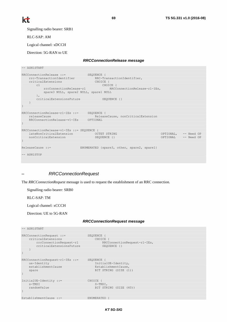
KT 5G-SIG
TS 5G.331 v1.0 (2016-08) 69
Signalling radio bearer: SRB1
RLC-SAP: AM
Logical channel: xDCCH
Direction: 5G-RAN to UE
RRCConnectionRelease message
-- ASN1START
RRCConnectionRelease ::= SEQUENCE {
rrc-TransactionIdentifier RRC-TransactionIdentifier,
criticalExtensions CHOICE {
c1 CHOICE {
rrcConnectionRelease-r1 RRCConnectionRelease-r1-IEs,
spare3 NULL, spare2 NULL, spare1 NULL
},
criticalExtensionsFuture SEQUENCE {}
}
}
RRCConnectionRelease-r1-IEs ::= SEQUENCE {
releaseCause ReleaseCause, nonCriticalExtension
RRCConnectionRelease-v1-IEs OPTIONAL
}
RRCConnectionRelease-v1-IEs ::= SEQUENCE {
lateNonCriticalExtension OCTET STRING OPTIONAL, -- Need OP
nonCriticalExtension SEQUENCE {} OPTIONAL -- Need OP
}
ReleaseCause ::= ENUMERATED {spare3, other, spare2, spare1}
-- ASN1STOP
– RRCConnectionRequest
The RRCConnectionRequest message is used to request the establishment of an RRC connection.
Signalling radio bearer: SRB0
RLC-SAP: TM
Logical channel: xCCCH
Direction: UE to 5G-RAN
RRCConnectionRequest message
-- ASN1START
RRCConnectionRequest ::= SEQUENCE {
criticalExtensions CHOICE {
rrcConnectionRequest-r1 RRCConnectionRequest-r1-IEs,
criticalExtensionsFuture SEQUENCE {}
}
}
RRCConnectionRequest-r1-IEs ::= SEQUENCE {
ue-Identity InitialUE-Identity,
establishmentCause EstablishmentCause,
spare BIT STRING (SIZE (1))
}
InitialUE-Identity ::= CHOICE {
s-TMSI S-TMSI,
randomValue BIT STRING (SIZE (40))
}
EstablishmentCause ::= ENUMERATED {

KT 5G-SIG
TS 5G.331 v1.0 (2016-08) 70
mo-Signalling, mo-Data,
spare1, spare2, spare3, spare4, spare5, spare6}
-- ASN1STOP
– RRCConnectionSetup
The RRCConnectionSetup message is used to establish SRB1.
Signalling radio bearer: SRB0
RLC-SAP: TM
Logical channel: xCCCH
Direction: 5G-RAN to UE
RRCConnectionSetup message
-- ASN1START
RRCConnectionSetup ::= SEQUENCE {
rrc-TransactionIdentifier RRC-TransactionIdentifier,
criticalExtensions CHOICE {
c1 CHOICE {
rrcConnectionSetup-r1 RRCConnectionSetup-r1-IEs,
spare7 NULL,
spare6 NULL, spare5 NULL, spare4 NULL,
spare3 NULL, spare2 NULL, spare1 NULL
},
criticalExtensionsFuture SEQUENCE {}
}
}
RRCConnectionSetup-r1-IEs ::= SEQUENCE {
radioResourceConfigDedicated RadioResourceConfigDedicated,
nonCriticalExtension RRCConnectionSetup-v1-IEs OPTIONAL
}
RRCConnectionSetup-v1-IEs ::= SEQUENCE {
lateNonCriticalExtension OCTET STRING OPTIONAL,
nonCriticalExtension SEQUENCE {} OPTIONAL
}
-- ASN1STOP
– RRCConnectionSetupComplete
The RRCConnectionSetupComplete message is used to confirm the successful completion of an RRC connection
establishment.
Signalling radio bearer: SRB1
RLC-SAP: AM
Logical channel: xDCCH
Direction: UE to 5G-RAN
RRCConnectionSetupComplete message
-- ASN1START
RRCConnectionSetupComplete ::= SEQUENCE {
rrc-TransactionIdentifier RRC-TransactionIdentifier,
criticalExtensions CHOICE {
c1 CHOICE{

KT 5G-SIG
TS 5G.331 v1.0 (2016-08) 71
rrcConnectionSetupComplete-r1 RRCConnectionSetupComplete-r1-IEs,
spare3 NULL, spare2 NULL, spare1 NULL
},
criticalExtensionsFuture SEQUENCE {}
}
}
RRCConnectionSetupComplete-r1-IEs ::= SEQUENCE {
dedicatedInfoNAS DedicatedInfoNAS,
selectedPLMN-Identity INTEGER (1..maxPLMN),
registeredMME RegisteredMME OPTIONAL,
gummei-Type ENUMERATED {native, spare} OPTIONAL,
nonCriticalExtension RRCConnectionSetupComplete-v1-IEs OPTIONAL
}
RRCConnectionSetupComplete-v1-IEs ::= SEQUENCE {
lateNonCriticalExtension OCTET STRING OPTIONAL,
nonCriticalExtension SEQUENCE {} OPTIONAL
}
RegisteredMME ::= SEQUENCE {
plmn-Identity PLMN-Identity OPTIONAL,
mmegi BIT STRING (SIZE (16)),
mmec MMEC
}
-- ASN1STOP
– SecurityModeCommand
The SecurityModeCommand message is used to command the activation of AS security.
Signalling radio bearer: SRB1
RLC-SAP: AM
Logical channel: xDCCH
Direction: 5G-RAN to UE
SecurityModeCommand message
-- ASN1START
SecurityModeCommand ::= SEQUENCE {
rrc-TransactionIdentifier RRC-TransactionIdentifier,
criticalExtensions CHOICE {
c1 CHOICE{
securityModeCommand-r1 SecurityModeCommand-r1-IEs,
spare3 NULL, spare2 NULL, spare1 NULL
},
criticalExtensionsFuture SEQUENCE {}
}
}
SecurityModeCommand-r1-IEs ::= SEQUENCE {
securityConfigSMC SecurityConfigSMC,
nonCriticalExtension SecurityModeCommand-v1-IEs OPTIONAL
}
SecurityModeCommand-v1-IEs ::= SEQUENCE {
lateNonCriticalExtension OCTET STRING OPTIONAL, -- Need OP
nonCriticalExtension SEQUENCE {} OPTIONAL -- Need OP
}
SecurityConfigSMC ::= SEQUENCE {
securityAlgorithmConfig SecurityAlgorithmConfig,
...
}
-- ASN1STOP

KT 5G-SIG
TS 5G.331 v1.0 (2016-08) 72
– SecurityModeComplete
The SecurityModeComplete message is used to confirm the successful completion of a security mode command.
Signalling radio bearer: SRB1
RLC-SAP: AM
Logical channel: xDCCH
Direction: UE to 5G-RAN
SecurityModeComplete message
-- ASN1START
SecurityModeComplete ::= SEQUENCE {
rrc-TransactionIdentifier RRC-TransactionIdentifier,
criticalExtensions CHOICE {
securityModeComplete-r1 SecurityModeComplete-r1-IEs,
criticalExtensionsFuture SEQUENCE {}
}
}
SecurityModeComplete-r1-IEs ::= SEQUENCE {
nonCriticalExtension SecurityModeComplete-v1-IEs OPTIONAL
}
SecurityModeComplete-v1-IEs ::= SEQUENCE {
lateNonCriticalExtension OCTET STRING OPTIONAL,
nonCriticalExtension SEQUENCE {} OPTIONAL
}
-- ASN1STOP
– SecurityModeFailure
The SecurityModeFailure message is used to indicate an unsuccessful completion of a security mode command.
Signalling radio bearer: SRB1
RLC-SAP: AM
Logical channel: xDCCH
Direction: UE to 5G-RAN
SecurityModeFailure message
-- ASN1START
SecurityModeFailure ::= SEQUENCE {
rrc-TransactionIdentifier RRC-TransactionIdentifier,
criticalExtensions CHOICE {
securityModeFailure-r1 SecurityModeFailure-r1-IEs,
criticalExtensionsFuture SEQUENCE {}
}
}
SecurityModeFailure-r1-IEs ::= SEQUENCE {
nonCriticalExtension SecurityModeFailure-v1-IEs OPTIONAL
}
SecurityModeFailure-v1-IEs ::= SEQUENCE {
lateNonCriticalExtension OCTET STRING OPTIONAL,
nonCriticalExtension SEQUENCE {} OPTIONAL
}
-- ASN1STOP
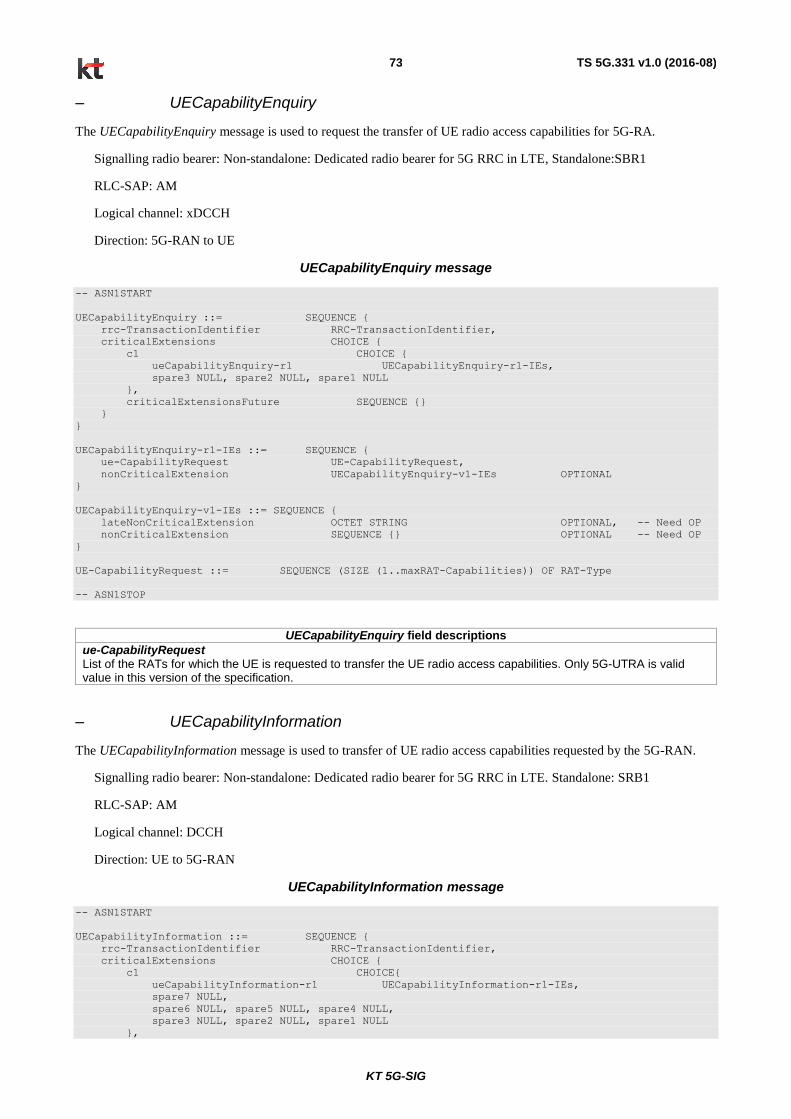
KT 5G-SIG
TS 5G.331 v1.0 (2016-08) 73
– UECapabilityEnquiry
The UECapabilityEnquiry message is used to request the transfer of UE radio access capabilities for 5G-RA.
Signalling radio bearer: Non-standalone: Dedicated radio bearer for 5G RRC in LTE, Standalone:SBR1
RLC-SAP: AM
Logical channel: xDCCH
Direction: 5G-RAN to UE
UECapabilityEnquiry message
-- ASN1START
UECapabilityEnquiry ::= SEQUENCE {
rrc-TransactionIdentifier RRC-TransactionIdentifier,
criticalExtensions CHOICE {
c1 CHOICE {
ueCapabilityEnquiry-r1 UECapabilityEnquiry-r1-IEs,
spare3 NULL, spare2 NULL, spare1 NULL
},
criticalExtensionsFuture SEQUENCE {}
}
}
UECapabilityEnquiry-r1-IEs ::= SEQUENCE {
ue-CapabilityRequest UE-CapabilityRequest,
nonCriticalExtension UECapabilityEnquiry-v1-IEs OPTIONAL
}
UECapabilityEnquiry-v1-IEs ::= SEQUENCE {
lateNonCriticalExtension OCTET STRING OPTIONAL, -- Need OP
nonCriticalExtension SEQUENCE {} OPTIONAL -- Need OP
}
UE-CapabilityRequest ::= SEQUENCE (SIZE (1..maxRAT-Capabilities)) OF RAT-Type
-- ASN1STOP
UECapabilityEnquiry field descriptions
ue-CapabilityRequest List of the RATs for which the UE is requested to transfer the UE radio access capabilities. Only 5G-UTRA is valid value in this version of the specification.
– UECapabilityInformation
The UECapabilityInformation message is used to transfer of UE radio access capabilities requested by the 5G-RAN.
Signalling radio bearer: Non-standalone: Dedicated radio bearer for 5G RRC in LTE. Standalone: SRB1
RLC-SAP: AM
Logical channel: DCCH
Direction: UE to 5G-RAN
UECapabilityInformation message
-- ASN1START
UECapabilityInformation ::= SEQUENCE {
rrc-TransactionIdentifier RRC-TransactionIdentifier,
criticalExtensions CHOICE {
c1 CHOICE{
ueCapabilityInformation-r1 UECapabilityInformation-r1-IEs,
spare7 NULL,
spare6 NULL, spare5 NULL, spare4 NULL,
spare3 NULL, spare2 NULL, spare1 NULL
},
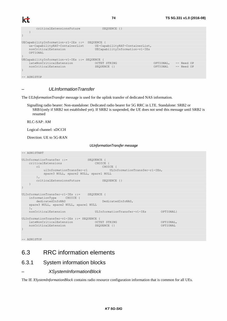
KT 5G-SIG
TS 5G.331 v1.0 (2016-08) 74
criticalExtensionsFuture SEQUENCE {}
}
}
UECapabilityInformation-r1-IEs ::= SEQUENCE {
ue-CapabilityRAT-ContainerList UE-CapabilityRAT-ContainerList,
nonCriticalExtension UECapabilityInformation-v1-IEs
OPTIONAL
}
UECapabilityInformation-v1-IEs ::= SEQUENCE {
lateNonCriticalExtension OCTET STRING OPTIONAL, -- Need OP
nonCriticalExtension SEQUENCE {} OPTIONAL -- Need OP
}
-- ASN1STOP
– ULInformationTransfer
The ULInformationTransfer message is used for the uplink transfer of dedicated NAS information.
Signalling radio bearer: Non-standalone: Dedicated radio bearer for 5G RRC in LTE. Standalone: SRB2 or
SRB1(only if SRB2 not established yet). If SRB2 is suspended, the UE does not send this message until SRB2 is
resumed
RLC-SAP: AM
Logical channel: xDCCH
Direction: UE to 5G-RAN
ULInformationTransfer message
-- ASN1START
ULInformationTransfer ::= SEQUENCE {
criticalExtensions CHOICE {
c1 CHOICE {
ulInformationTransfer-r1 ULInformationTransfer-r1-IEs,
spare3 NULL, spare2 NULL, spare1 NULL
},
criticalExtensionsFuture SEQUENCE {}
}
}
ULInformationTransfer-r1-IEs ::= SEQUENCE {
informationType CHOICE {
dedicatedInfoNAS DedicatedInfoNAS,
spare3 NULL, spare2 NULL, spare1 NULL
},
nonCriticalExtension ULInformationTransfer-v1-IEs OPTIONAL}
ULInformationTransfer-v1-IEs ::= SEQUENCE {
lateNonCriticalExtension OCTET STRING OPTIONAL,
nonCriticalExtension SEQUENCE {} OPTIONAL
}
-- ASN1STOP
6.3 RRC information elements
6.3.1 System information blocks
– XSystemInformationBlock
The IE XSystemInformationBlock contains radio resource configuration information that is common for all UEs.
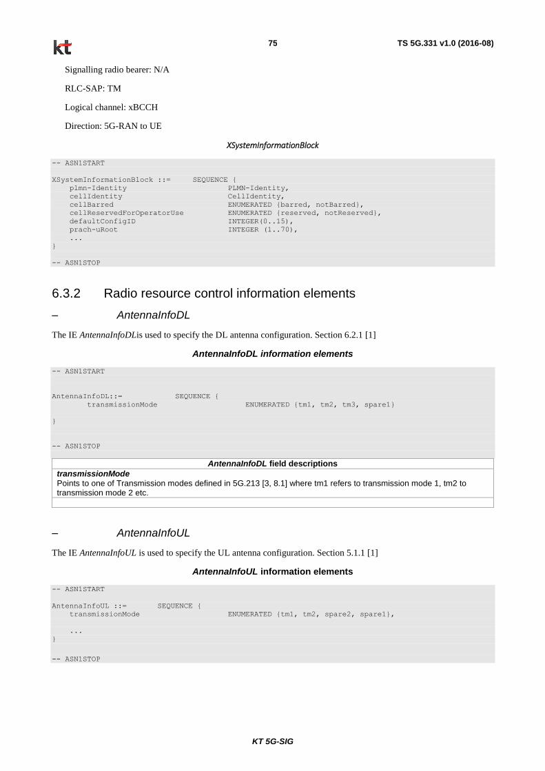
KT 5G-SIG
TS 5G.331 v1.0 (2016-08) 75
Signalling radio bearer: N/A
RLC-SAP: TM
Logical channel: xBCCH
Direction: 5G-RAN to UE
XSystemInformationBlock
-- ASN1START
XSystemInformationBlock ::= SEQUENCE {
plmn-Identity PLMN-Identity,
cellIdentity CellIdentity,
cellBarred ENUMERATED {barred, notBarred},
cellReservedForOperatorUse ENUMERATED {reserved, notReserved},
defaultConfigID INTEGER(0..15),
prach-uRoot INTEGER (1..70),
...
}
-- ASN1STOP
6.3.2 Radio resource control information elements
– AntennaInfoDL
The IE AntennaInfoDLis used to specify the DL antenna configuration. Section 6.2.1 [1]
AntennaInfoDL information elements
-- ASN1START
AntennaInfoDL::= SEQUENCE {
transmissionMode ENUMERATED {tm1, tm2, tm3, spare1}
}
-- ASN1STOP
AntennaInfoDL field descriptions
transmissionMode Points to one of Transmission modes defined in 5G.213 [3, 8.1] where tm1 refers to transmission mode 1, tm2 to transmission mode 2 etc.
– AntennaInfoUL
The IE AntennaInfoUL is used to specify the UL antenna configuration. Section 5.1.1 [1]
AntennaInfoUL information elements
-- ASN1START
AntennaInfoUL ::= SEQUENCE {
transmissionMode ENUMERATED {tm1, tm2, spare2, spare1},
...
}
-- ASN1STOP
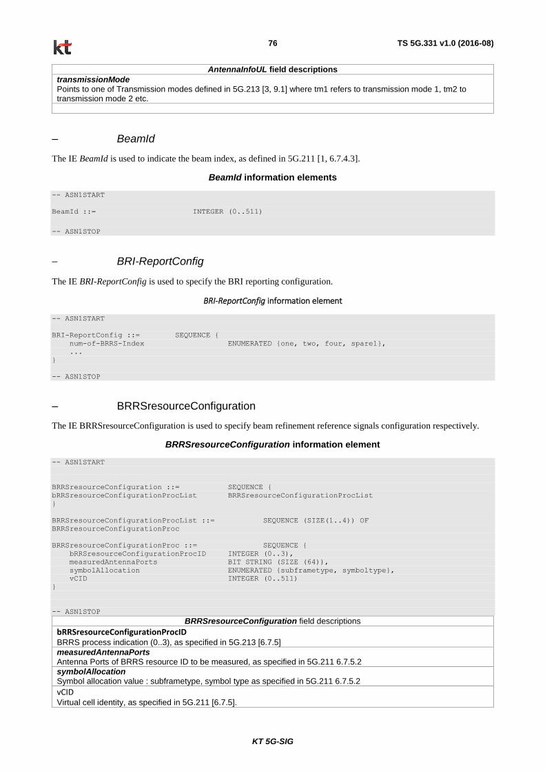
KT 5G-SIG
TS 5G.331 v1.0 (2016-08) 76
AntennaInfoUL field descriptions
transmissionMode Points to one of Transmission modes defined in 5G.213 [3, 9.1] where tm1 refers to transmission mode 1, tm2 to transmission mode 2 etc.
– BeamId
The IE BeamId is used to indicate the beam index, as defined in 5G.211 [1, 6.7.4.3].
BeamId information elements
-- ASN1START
BeamId ::= INTEGER (0..511)
-- ASN1STOP
– BRI-ReportConfig
The IE BRI-ReportConfig is used to specify the BRI reporting configuration.
BRI-ReportConfig information element
-- ASN1START
BRI-ReportConfig ::= SEQUENCE {
num-of-BRRS-Index ENUMERATED {one, two, four, spare1},
...
}
-- ASN1STOP
– BRRSresourceConfiguration
The IE BRRSresourceConfiguration is used to specify beam refinement reference signals configuration respectively.
BRRSresourceConfiguration information element
-- ASN1START
BRRSresourceConfiguration ::= SEQUENCE {
bRRSresourceConfigurationProcList BRRSresourceConfigurationProcList
}
BRRSresourceConfigurationProcList ::= SEQUENCE (SIZE(1..4)) OF
BRRSresourceConfigurationProc
BRRSresourceConfigurationProc ::= SEQUENCE {
bRRSresourceConfigurationProcID INTEGER (0..3),
measuredAntennaPorts BIT STRING (SIZE (64)),
symbolAllocation ENUMERATED {subframetype, symboltype},
vCID INTEGER (0..511)
}
-- ASN1STOP
BRRSresourceConfiguration field descriptions
bRRSresourceConfigurationProcID BRRS process indication (0..3), as specified in 5G.213 [6.7.5]
measuredAntennaPorts Antenna Ports of BRRS resource ID to be measured, as specified in 5G.211 6.7.5.2
symbolAllocation Symbol allocation value : subframetype, symbol type as specified in 5G.211 6.7.5.2
vCID Virtual cell identity, as specified in 5G.211 [6.7.5].

KT 5G-SIG
TS 5G.331 v1.0 (2016-08) 77
– CQI-ReportConfig
The IE CQI-ReportConfig is used to specify the CQI reporting configuration.
CQI-ReportConfig information elements
-- ASN1START
CQI-ReportConfig ::= CHOICE {
cQI-Report-ProcList CQI-Report-ProcList
}
CQI-Report-ProcList ::= SEQUENCE (SIZE (1..4)) OF CQI-ReportProc
CQI-ReportProc ::= CHOICE {
release NULL,
setup SEQUENCE {
cQI-ConfigurationID INTEGER(0..3),
cSI-RS-COnfig CSI-RS-Config OPTIONAL, -- Need OR
pmi-RI-Report ENUMERATED {setup} OPTIONAL, -- Need OR
cqi-ReportModeAperiodic CQI-ReportModeAperiodic OPTIONAL -- Need OR
},
...
}
CQI-ReportModeAperiodic ::= ENUMERATED {
rm10, rm11, spare2, spare1
}
-- ASN1STOP
– CSI-RS-Config
The IE CSI-RS-Config is used to specify the CSI-RS reporting configuration.
CSI-RS-Config information elements
-- ASN1START
CSI-RS-Config ::= CHOICE {
release NULL,
setup SEQUENCE {
pcRatio INTEGER (-8..15),
resourceConfig BIT STRING (SIZE (16)),
scramblingIdentity INTEGER (0..503)
},
...
}
-- ASN1STOP
CSI-RS-Config field descriptions
pcRatio pcRatio is the assumed ratio of PDSCH EPRE to CSI-RS EPRE when UE derives CSI feedback and takes values in the range of [-8, 15] dB with 1 dB step size as specified in 5G.213
resourceConfig CSI-RS resource configuration including the information of CSI-RS antenna port and RE mapping. The allowable values and port mapping are given in subclause 6.7.3.2 of 5G.211. scramblingIdentity scrambling sequence initialization parameter as specified in subclause 6.7.3.1 of 5G.211.

KT 5G-SIG
TS 5G.331 v1.0 (2016-08) 78
– DedicatedInfoNAS
The IE DedicatedInfoNAS is used to transfer UE specific NAS layer information between the network and the UE. The
RRC layer is transparent for this information.
DedicatedInfoNAS information element
-- ASN1START
DedicatedInfoNAS ::= OCTET STRING
-- ASN1STOP
– DMRS-ConfigDL
The IE DMRS-ConfigDL is the DMRS configuration that 5G-RAN may configure on a serving frequency in DL.
DMRS-ConfigDL information elements
-- ASN1START
DMRS-ConfigDL::= CHOICE {
release NULL,
setup SEQUENCE {
dmrs-ScramblingSequenceInt-0 INTEGER (0..503),
dmrs-ScramblingSequenceInt-1 INTEGER (0..503),
high-speed-flag ENUMERATED {true} OPTIONAL,
...
}
}
-- ASN1STOP
DMRS-ConfigDL field descriptions
dmrs-SramblingSequenceInt-0, dmrs-SramblingSequenceInt-1,
The DMRS scrambling sequence initialization parameter inDMRS,ID
defined in 5G.211 [6.7.2.1].
– DMRS-ConfigUL
The IE DMRS-ConfigUL is the DMRS configuration that 5G-RAN may configure on a serving frequency in UL.
DMRS-ConfigUL information elements
-- ASN1START
DMRS-ConfigUL ::= CHOICE {
release NULL,
setup SEQUENCE {
dmrs-ScramblingSequenceInt-0 INTEGER (0..503),
dmrs-ScramblingSequenceInt-1 INTEGER (0..503),
high-speed-flag ENUMERATED {true} OPTIONAL,
...
}
}
-- ASN1STOP
DMRS-ConfigUL field descriptions
dmrs-SramblingSequenceInt-0, dmrs-SramblingSequenceInt-1,
The DMRS scrambling sequence initialization parameter inDMRS,ID
defined in 5G.211 [5.5.2.1]
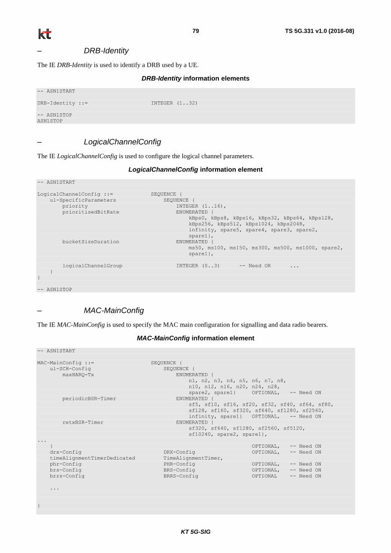
KT 5G-SIG
TS 5G.331 v1.0 (2016-08) 79
– DRB-Identity
The IE DRB-Identity is used to identify a DRB used by a UE.
DRB-Identity information elements
-- ASN1START
DRB-Identity ::= INTEGER (1..32)
-- ASN1STOP
ASN1STOP
– LogicalChannelConfig
The IE LogicalChannelConfig is used to configure the logical channel parameters.
LogicalChannelConfig information element
-- ASN1START
LogicalChannelConfig ::= SEQUENCE {
ul-SpecificParameters SEQUENCE {
priority INTEGER (1..16),
prioritisedBitRate ENUMERATED {
kBps0, kBps8, kBps16, kBps32, kBps64, kBps128,
kBps256, kBps512, kBps1024, kBps2048,
infinity, spare5, spare4, spare3, spare2,
spare1},
bucketSizeDuration ENUMERATED {
ms50, ms100, ms150, ms300, ms500, ms1000, spare2,
spare1},
logicalChannelGroup INTEGER (0..3) -- Need OR ...
}
}
-- ASN1STOP
– MAC-MainConfig
The IE MAC-MainConfig is used to specify the MAC main configuration for signalling and data radio bearers.
MAC-MainConfig information element
-- ASN1START
MAC-MainConfig ::= SEQUENCE {
ul-SCH-Config SEQUENCE {
maxHARQ-Tx ENUMERATED {
n1, n2, n3, n4, n5, n6, n7, n8,
n10, n12, n16, n20, n24, n28,
spare2, spare1} OPTIONAL, -- Need ON
periodicBSR-Timer ENUMERATED {
sf5, sf10, sf16, sf20, sf32, sf40, sf64, sf80,
sf128, sf160, sf320, sf640, sf1280, sf2560,
infinity, spare1} OPTIONAL, -- Need ON
retxBSR-Timer ENUMERATED {
sf320, sf640, sf1280, sf2560, sf5120,
sf10240, spare2, spare1},
...
} OPTIONAL, -- Need ON
drx-Config DRX-Config OPTIONAL, -- Need ON
timeAlignmentTimerDedicated TimeAlignmentTimer,
phr-Config PHR-Config OPTIONAL, -- Need ON
brs-Config BRS-Config OPTIONAL, -- Need ON
brrs-Config BRRS-Config OPTIONAL -- Need ON
...
}

KT 5G-SIG
TS 5G.331 v1.0 (2016-08) 80
DRX-Config ::= CHOICE {
release NULL,
setup SEQUENCE {
onDurationTimer ENUMERATED {
psf1, psf2, psf3, psf4, psf5, psf6,
psf8, psf10, psf20, psf30, psf40,
psf50, psf60, psf80, psf100,
psf200},
drx-InactivityTimer ENUMERATED {
psf1, psf2, psf3, psf4, psf5, psf6,
psf8, psf10, psf20, psf30, psf40,
psf50, psf60, psf80, psf100,
psf200, psf300, psf500, psf750,
psf1280, psf1920, psf2560, spare10,
spare9, spare8, spare7, spare6,
spare5, spare4, spare3, spare2,
spare1},
drx-RetransmissionTimer ENUMERATED {
psf1, psf2, psf4, psf5, psf6, psf8,psf10, psf16,
psf20, psf24, psf30, psf33, psf40, psf50, psf120,
psf165},
longDRX-CycleStartOffset CHOICE {
sf10 INTEGER(0..9),
sf20 INTEGER(0..19),
sf32 INTEGER(0..31),
sf40 INTEGER(0..39),
sf64 INTEGER(0..63),
sf80 INTEGER(0..79),
sf128 INTEGER(0..127),
sf160 INTEGER(0..159),
sf256 INTEGER(0..255),
sf320 INTEGER(0..319),
sf512 INTEGER(0..511),
sf640 INTEGER(0..639),
sf1024 INTEGER(0..1023),
sf1280 INTEGER(0..1279),
sf2048 INTEGER(0..2047),
sf2560 INTEGER(0..2559)
},
shortDRX SEQUENCE {
shortDRX-Cycle ENUMERATED {
sf2, sf5, sf8, sf10, sf16, sf20,
sf32, sf40, sf64, sf80, sf128, sf160,
sf256, sf320, sf512, sf640},
drxShortCycleTimer INTEGER (1..16)
} OPTIONAL -- Need OR
},
...
}
PHR-Config ::= CHOICE {
release NULL,
setup SEQUENCE {
periodicPHR-Timer ENUMERATED {sf10, sf20, sf50, sf100, sf200,
sf500, sf1000, infinity},
prohibitPHR-Timer ENUMERATED {sf0, sf10, sf20, sf50, sf100,
sf200, sf500, sf1000},
dl-PathlossChange ENUMERATED {dB1, dB3, dB6, infinity}
}
}
BRS-Config ::= CHOICE {
release NULL,
setup SEQUENCE {
beamTriggeringRSRPoffset ENUMERATED {dB-24, dB-22, dB-20, dB-18, dB-16, dB-14,
dB-12, dB-10, dB-8, dB-6, dB-5, dB-4, dB-3,dB-2,
dB-1, dB0, dB1, dB2, dB3, dB4, dB5,dB6, dB8, dB10,
dB12, dB14, dB16, dB18, dB20, dB22, dB24}
}
}
BRRS-Config ::= CHOICE {
release NULL,
setup SEQUENCE {
barRequestAllowed ENUMERATED {true} OPTIONAL,
prohibitBAR-Timer ENUMERATED {sf0, sf10, sf20, sf40, sf80,sf160,

KT 5G-SIG
TS 5G.331 v1.0 (2016-08) 81
sf320, sf640} OPTIONAL, -- Need ON
...
}
}
-- ASN1STOP
MAC-MainConfig field descriptions
maxHARQ-Tx Maximum number of transmissions for UL HARQ in 5G.321 [6].
periodicBSR-Timer
Timer for BSR reporting in 5G.321 [6]. Value in number of sub-frames. Value sf10 corresponds to 10 sub-frames, sf20 corresponds to 20 sub-frames and so on.
retxBSR-Timer
Timer for BSR reporting in 5G.321 [6]. Value in number of sub-frames. Value sf640 corresponds to 640 sub-frames, sf1280 corresponds to 1280 sub-frames and so on.
longDRX-CycleStartOffset longDRX-Cycle and drxStartOffset in 5G.321 [6]. The value of longDRX-Cycle is in number of sub-frames. Value sf10 corresponds to 10 sub-frames, sf20 corresponds to 20 sub-frames and so on. If shortDRX-Cycle is configured, the value of longDRX-Cycle shall be a multiple of the shortDRX-Cycle value. The value of drxStartOffset value is in number of sub-frames.
periodicPHR-Timer Timer for PHR reporting in 5G.321 [6]. Value in number of sub-frames. Value sf10 corresponds to 10 subframes, sf20 corresponds to 20 subframes and so on
prohibitPHR-Timer
Timer for PHR reporting in 5G.321 [6]. Value in number of sub-frames. Value sf0 corresponds to 0 subframes, sf100 corresponds to 100 subframes and so on.
dl-PathlossChange
DL Pathloss Change for PHR reporting in 5G.321 [6]. Value in dB. Value dB1 corresponds to 1 dB, dB3 corresponds to 3 dB and so on.
prohibitBAR-Timer Timer for BAR reporting in 5G.321. Value in number of sub-frames. Value sf0 corresponds to 0 subframes, sf640 corresponds to 640 subframes and so on.
beamTriggeringRSRPoffset Indicates the RSRP threshold (in dB) used by the UE to trigger BRS-based beam feedback transmission in 5G.321 [6].
– PDCCH-Config
The IE PDCCH-Config is used to specify the UE specific xPDCCH configuration. Subclause 6.6.1 [1]
PDCCH-Config information element
-- ASN1START
PDCCH-ConfigDedicated::= SEQUENCE {
xpdcch-format XPDCCH-format,
dmrs-pdcchConfigDL DMRS-PDCCHConfigDL,
...
}
XPDCCH-format::= SEQUENCE {
xpdcchSymbol ENUMERATED {sym1, sym2},
...
}
DMRS-PDCCHConfigDL::= SEQUENCE {
dmrs-ScramblingSequenceInt INTEGER (0..503),
...
}
-- ASN1STOP

KT 5G-SIG
TS 5G.331 v1.0 (2016-08) 82
PDCCH-Config field descriptions
xPDCCHSymbol Defines the number of symbols used for PDCCH transmission that UE shall monitor.
dmrs-SramblingSequenceInt
The DMRS scrambling sequence initialization parameter xPDCCHID,in defined in 5G.211 [6.7.1.1].
– PDCP-Config
The IE PDCP-Config is used to set the configurable PDCP parameters for data radio bearers.
PDCP-Config information element
-- ASN1START
PDCP-Config ::= SEQUENCE {
discardTimer ENUMERATED {
ms50, ms100, ms150, ms300, ms500,
ms750, ms1500, infinity
} OPTIONAL, -- Cond Setup
rlc-AM SEQUENCE {
statusReportRequired BOOLEAN
} OPTIONAL -- Cond Rlc-AM
}
-- ASN1STOP
– PDSCH-ConfigCommon
The IE PDSCH-ConfigCommon is used to specify the common PDSCH configuration respectively.
PDSCH-ConfigCommon information element
-- ASN1START
PDSCH-ConfigCommon::= SEQUENCE {
beamReferenceSignalPower INTEGER (-60..50),
dmrsPrecodingRBGroup ENUMERATED {opt1, opt2},
...
}
-- ASN1STOP
PDSCH-ConfigCommon field descriptions
beamReferenceSignalPower Parameter: Reference-signal power, which provides the downlink reference-signal EPRE, see TS 5G.213. The actual value in dBm.
dmrsPrecodingRBGroup dmrsPrecodingRBGroup provides information of precoding granularity of xPDSCH where opt1 means four PRBs mapped to a single VRBG index and opt2 means all assigned PRBs in the frequency domain [5G.213]
– PDSCH-ConfigDedicated
The IE PDSCH-ConfigDedicated is used to specify the UE specific PDSCH configuration respectively.
PDSCH-Config information element
-- ASN1START
PDSCH-ConfigDedicated::= SEQUENCE {
dmrs-ConfigDL DMRS-ConfigDL,
bRRSresourceConfiguration BRRSresourceConfiguration,
...
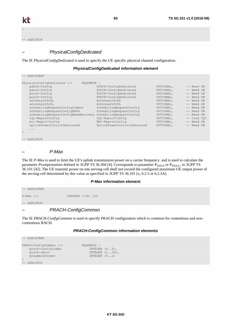
KT 5G-SIG
TS 5G.331 v1.0 (2016-08) 83
}
-- ASN1STOP
– PhysicalConfigDedicated
The IE PhysicalConfigDedicated is used to specify the UE specific physical channel configuration.
PhysicalConfigDedicated information element
-- ASN1START
PhysicalConfigDedicated ::= SEQUENCE {
pdsch-Config PDSCH-ConfigDedicated OPTIONAL, -- Need ON
pdcch-Config PDCCH-ConfigDedicated OPTIONAL, -- Need ON
pucch-Config PUCCH-ConfigDedicated OPTIONAL, -- Need ON
pusch-Config PUSCH-ConfigDedicated OPTIONAL, -- Need ON
antennaInfoDL AntennaInfoDL OPTIONAL, -- Need ON
antennaInfoUL AntennaInfoUL OPTIONAL, -- Need ON
schedulingRequestConfigCommon SchedulingRequestConfig OPTIONAL, -- Need ON
schedulingRequestConfigBRRS SchedulingRequestConfig OPTIONAL, -- Need ON
schedulingRequestConfigBeamRecovery SchedulingRequestConfig OPTIONAL, -- Need ON
cqi-ReportConfig CQI-ReportConfig OPTIONAL, -- Cond CQI
bri-ReportConfig BRI-ReportConfig OPTIONAL, -- Need ON
uplinkPowerControlDedicated UplinkPowerControlDedicated OPTIONAL, -- Need ON
...
}
-- ASN1STOP
– P-Max
The IE P-Max is used to limit the UE's uplink transmission power on a carrier frequency. and is used to calculate the
parameter Pcompensation defined in 3GPP TS 36.304 [4]. Corresponds to parameter PEMAX or PEMAX,c in 3GPP TS
36.101 [42]. The UE transmit power on one serving cell shall not exceed the configured maximum UE output power of
the serving cell determined by this value as specified in 3GPP TS 36.101 [x, 6.2.5 or 6.2.5A].
P-Max information element
-- ASN1START
P-Max ::= INTEGER (-30..33)
-- ASN1STOP
– PRACH-ConfigCommon
The IE PRACH-ConfigCommon is used to specify PRACH configuration which is common for contentious and non-
contentious RACH.
PRACH-ConfigCommon information elements
-- ASN1START
PRACH-ConfigCommon ::= SEQUENCE {
prach-ConfigIndex INTEGER (0..3),
prach-uRoot INTEGER (1..70),
preambleFormat INTEGER (0..1)
}
-- ASN1STOP

KT 5G-SIG
TS 5G.331 v1.0 (2016-08) 84
PRACH-Config field descriptions
prach-uRoot the root 𝑢 as specified in 5G.211 5.7.1
prach-ConfigIndex As specified in 5G.211 table 5.7.1-2
preambleFormat Parameter indicating which RACH preamble format is used in cell, where 0 is for 500 meter coverage and 1 is for 1 killometer coverage.
– PUCCH-Config
The IE PUCCH-ConfigDedicated is used to specify the UE specific PUCCH configuration.
PUCCH-Config information elements
-- ASN1START
PUCCH-ConfigDedicated ::= SEQUENCE {
twoAntennaPortActivated ENUMERATED {true} OPTIONAL, -- Need ON
...
}
-- ASN1STOP
PUCCH-ConfigDedicated field descriptions
twoAntennaPortActived Indicates whether two antenna ports are configured for PUCCH, see 5G.213[3,11.1].
– PUSCH-Config
The IE PUSCH-ConfigDedicated is used to specify the UE specific PUSCH configuration.
PUSCH-Config information element
-- ASN1START
PUSCH-ConfigDedicated ::= SEQUENCE {
dmrs-ConfigUL DMRS-ConfigUL,
soundingRS-UL-ConfigDedicated SoundingRS-UL-ConfigDedicated OPTIONAL, -- Need OR
...
}
-- ASN1STOP
- RACH-ConfigCommon
The IE RACH-ConfigCommon is used to specify the generic random access parameters..
RACH-ConfigCommon information elements
-- ASN1START
RACH-ConfigCommon ::= SEQUENCE {
numberOfRA-Preambles ENUMERATED {
n3, n6, n9, n12, n15, n18, n21, n24, n27, n30, n33, n36, n39,
n42, n45, n48},
powerRampingParameters PowerRampingParameters,
ra-SupervisionInfo SEQUENCE {
preambleTransMax PreambleTransMax,
ra-ResponseWindowSize ENUMERATED {
sf5, sf10, sf15, sf20, sf25, sf30,
sf40, sf50},
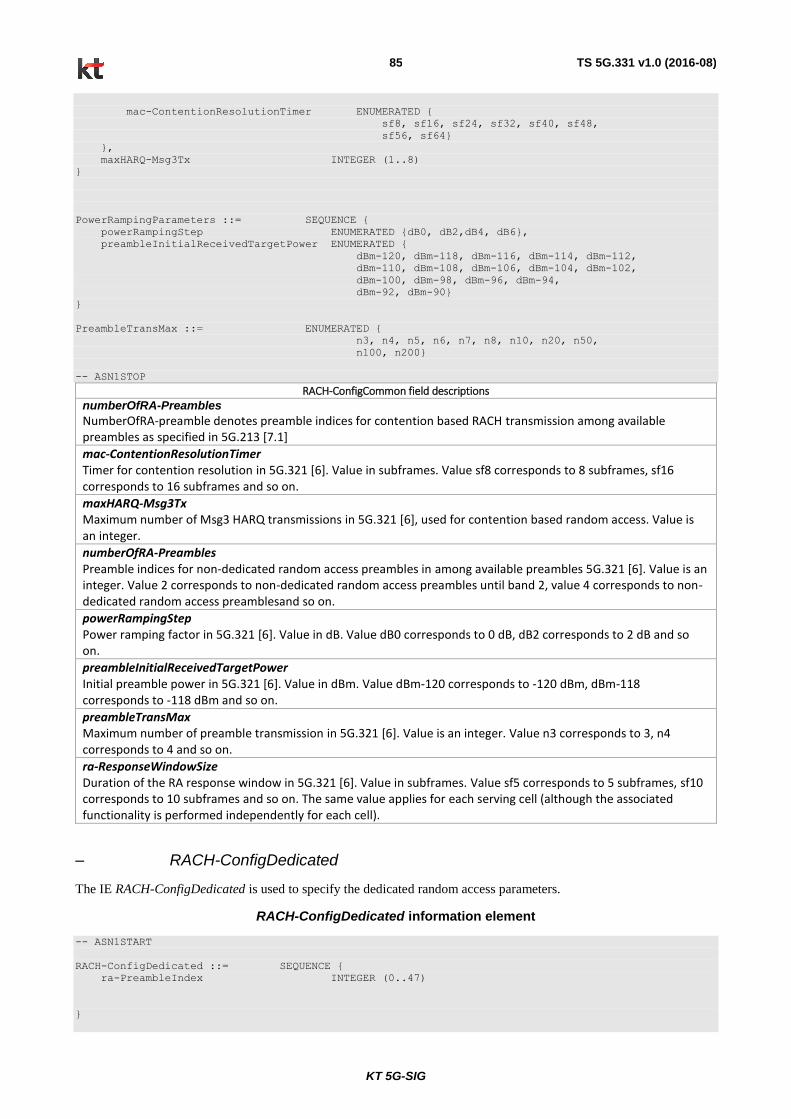
KT 5G-SIG
TS 5G.331 v1.0 (2016-08) 85
mac-ContentionResolutionTimer ENUMERATED {
sf8, sf16, sf24, sf32, sf40, sf48,
sf56, sf64}
},
maxHARQ-Msg3Tx INTEGER (1..8)
}
PowerRampingParameters ::= SEQUENCE {
powerRampingStep ENUMERATED {dB0, dB2,dB4, dB6},
preambleInitialReceivedTargetPower ENUMERATED {
dBm-120, dBm-118, dBm-116, dBm-114, dBm-112,
dBm-110, dBm-108, dBm-106, dBm-104, dBm-102,
dBm-100, dBm-98, dBm-96, dBm-94,
dBm-92, dBm-90}
}
PreambleTransMax ::= ENUMERATED {
n3, n4, n5, n6, n7, n8, n10, n20, n50,
n100, n200}
-- ASN1STOP
RACH-ConfigCommon field descriptions numberOfRA-Preambles
NumberOfRA-preamble denotes preamble indices for contention based RACH transmission among available preambles as specified in 5G.213 [7.1]
mac-ContentionResolutionTimer Timer for contention resolution in 5G.321 [6]. Value in subframes. Value sf8 corresponds to 8 subframes, sf16 corresponds to 16 subframes and so on.
maxHARQ-Msg3Tx Maximum number of Msg3 HARQ transmissions in 5G.321 [6], used for contention based random access. Value is an integer.
numberOfRA-Preambles Preamble indices for non-dedicated random access preambles in among available preambles 5G.321 [6]. Value is an integer. Value 2 corresponds to non-dedicated random access preambles until band 2, value 4 corresponds to non-dedicated random access preamblesand so on.
powerRampingStep Power ramping factor in 5G.321 [6]. Value in dB. Value dB0 corresponds to 0 dB, dB2 corresponds to 2 dB and so on.
preambleInitialReceivedTargetPower Initial preamble power in 5G.321 [6]. Value in dBm. Value dBm-120 corresponds to -120 dBm, dBm-118 corresponds to -118 dBm and so on.
preambleTransMax Maximum number of preamble transmission in 5G.321 [6]. Value is an integer. Value n3 corresponds to 3, n4 corresponds to 4 and so on.
ra-ResponseWindowSize Duration of the RA response window in 5G.321 [6]. Value in subframes. Value sf5 corresponds to 5 subframes, sf10 corresponds to 10 subframes and so on. The same value applies for each serving cell (although the associated functionality is performed independently for each cell).
– RACH-ConfigDedicated
The IE RACH-ConfigDedicated is used to specify the dedicated random access parameters.
RACH-ConfigDedicated information element
-- ASN1START
RACH-ConfigDedicated ::= SEQUENCE {
ra-PreambleIndex INTEGER (0..47)
}
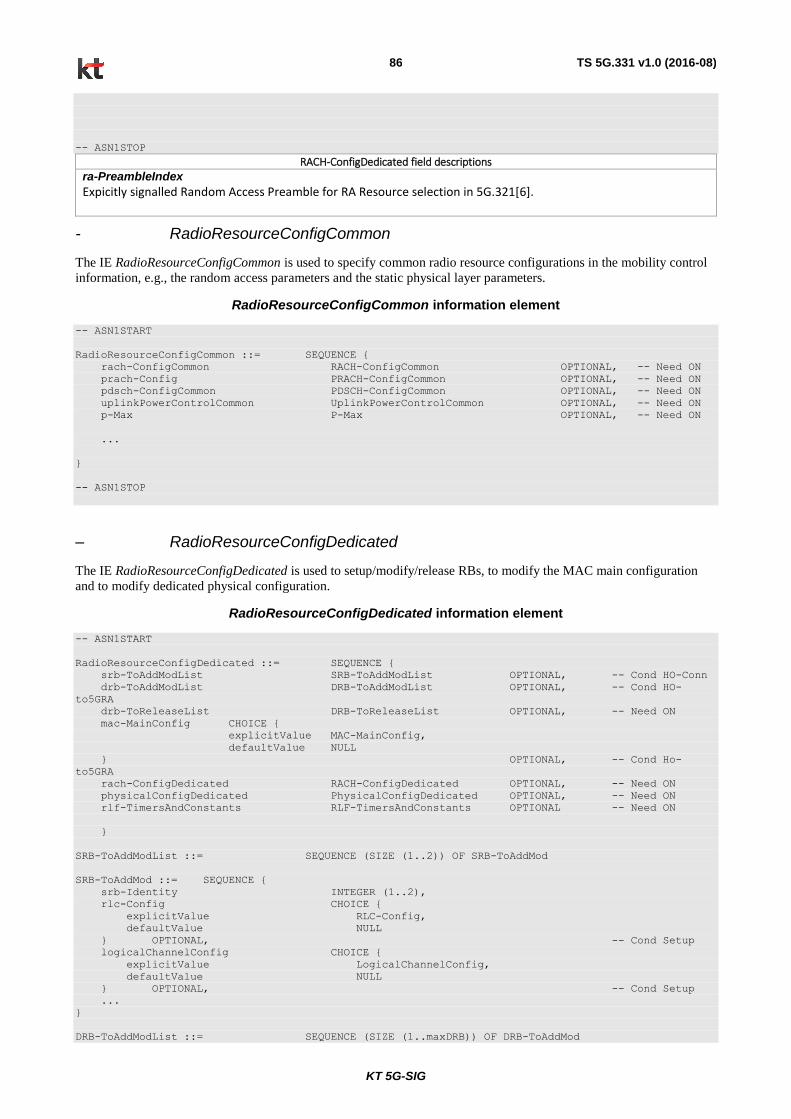
KT 5G-SIG
TS 5G.331 v1.0 (2016-08) 86
-- ASN1STOP
RACH-ConfigDedicated field descriptions ra-PreambleIndex
Expicitly signalled Random Access Preamble for RA Resource selection in 5G.321[6].
- RadioResourceConfigCommon
The IE RadioResourceConfigCommon is used to specify common radio resource configurations in the mobility control
information, e.g., the random access parameters and the static physical layer parameters.
RadioResourceConfigCommon information element
-- ASN1START
RadioResourceConfigCommon ::= SEQUENCE {
rach-ConfigCommon RACH-ConfigCommon OPTIONAL, -- Need ON
prach-Config PRACH-ConfigCommon OPTIONAL, -- Need ON
pdsch-ConfigCommon PDSCH-ConfigCommon OPTIONAL, -- Need ON
uplinkPowerControlCommon UplinkPowerControlCommon OPTIONAL, -- Need ON
p-Max P-Max OPTIONAL, -- Need ON
...
}
-- ASN1STOP
– RadioResourceConfigDedicated
The IE RadioResourceConfigDedicated is used to setup/modify/release RBs, to modify the MAC main configuration
and to modify dedicated physical configuration.
RadioResourceConfigDedicated information element
-- ASN1START
RadioResourceConfigDedicated ::= SEQUENCE {
srb-ToAddModList SRB-ToAddModList OPTIONAL, -- Cond HO-Conn
drb-ToAddModList DRB-ToAddModList OPTIONAL, -- Cond HO-
to5GRA
drb-ToReleaseList DRB-ToReleaseList OPTIONAL, -- Need ON
mac-MainConfig CHOICE {
explicitValue MAC-MainConfig,
defaultValue NULL
} OPTIONAL, -- Cond Ho-
to5GRA
rach-ConfigDedicated RACH-ConfigDedicated OPTIONAL, -- Need ON
physicalConfigDedicated PhysicalConfigDedicated OPTIONAL, -- Need ON
rlf-TimersAndConstants RLF-TimersAndConstants OPTIONAL -- Need ON
}
SRB-ToAddModList ::= SEQUENCE (SIZE (1..2)) OF SRB-ToAddMod
SRB-ToAddMod ::= SEQUENCE {
srb-Identity INTEGER (1..2),
rlc-Config CHOICE {
explicitValue RLC-Config,
defaultValue NULL
} OPTIONAL, -- Cond Setup
logicalChannelConfig CHOICE {
explicitValue LogicalChannelConfig,
defaultValue NULL
} OPTIONAL, -- Cond Setup
...
}
DRB-ToAddModList ::= SEQUENCE (SIZE (1..maxDRB)) OF DRB-ToAddMod
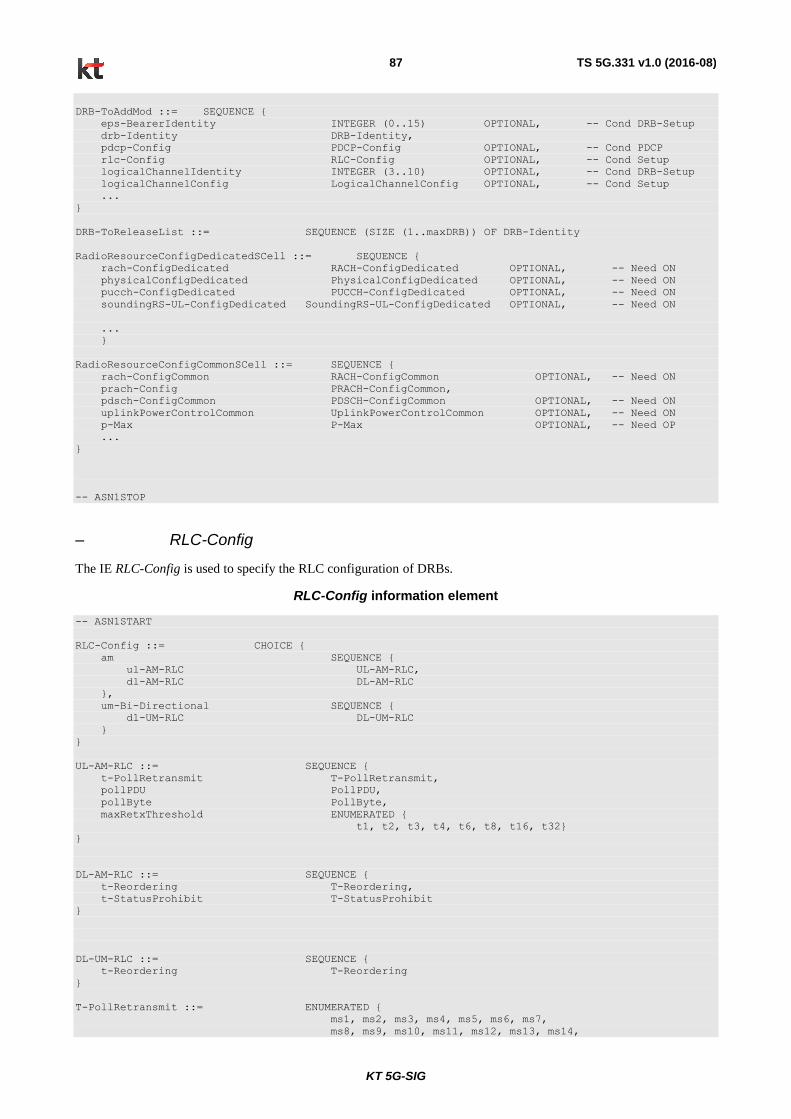
KT 5G-SIG
TS 5G.331 v1.0 (2016-08) 87
DRB-ToAddMod ::= SEQUENCE {
eps-BearerIdentity INTEGER (0..15) OPTIONAL, -- Cond DRB-Setup
drb-Identity DRB-Identity,
pdcp-Config PDCP-Config OPTIONAL, -- Cond PDCP
rlc-Config RLC-Config OPTIONAL, -- Cond Setup
logicalChannelIdentity INTEGER (3..10) OPTIONAL, -- Cond DRB-Setup
logicalChannelConfig LogicalChannelConfig OPTIONAL, -- Cond Setup
...
}
DRB-ToReleaseList ::= SEQUENCE (SIZE (1..maxDRB)) OF DRB-Identity
RadioResourceConfigDedicatedSCell ::= SEQUENCE {
rach-ConfigDedicated RACH-ConfigDedicated OPTIONAL, -- Need ON
physicalConfigDedicated PhysicalConfigDedicated OPTIONAL, -- Need ON
pucch-ConfigDedicated PUCCH-ConfigDedicated OPTIONAL, -- Need ON
soundingRS-UL-ConfigDedicated SoundingRS-UL-ConfigDedicated OPTIONAL, -- Need ON
...
}
RadioResourceConfigCommonSCell ::= SEQUENCE {
rach-ConfigCommon RACH-ConfigCommon OPTIONAL, -- Need ON
prach-Config PRACH-ConfigCommon,
pdsch-ConfigCommon PDSCH-ConfigCommon OPTIONAL, -- Need ON
uplinkPowerControlCommon UplinkPowerControlCommon OPTIONAL, -- Need ON
p-Max P-Max OPTIONAL, -- Need OP
...
}
-- ASN1STOP
– RLC-Config
The IE RLC-Config is used to specify the RLC configuration of DRBs.
RLC-Config information element
-- ASN1START
RLC-Config ::= CHOICE {
am SEQUENCE {
ul-AM-RLC UL-AM-RLC,
dl-AM-RLC DL-AM-RLC
},
um-Bi-Directional SEQUENCE {
dl-UM-RLC DL-UM-RLC
}
}
UL-AM-RLC ::= SEQUENCE {
t-PollRetransmit T-PollRetransmit,
pollPDU PollPDU,
pollByte PollByte,
maxRetxThreshold ENUMERATED {
t1, t2, t3, t4, t6, t8, t16, t32}
}
DL-AM-RLC ::= SEQUENCE {
t-Reordering T-Reordering,
t-StatusProhibit T-StatusProhibit
}
DL-UM-RLC ::= SEQUENCE {
t-Reordering T-Reordering
}
T-PollRetransmit ::= ENUMERATED {
ms1, ms2, ms3, ms4, ms5, ms6, ms7,
ms8, ms9, ms10, ms11, ms12, ms13, ms14,
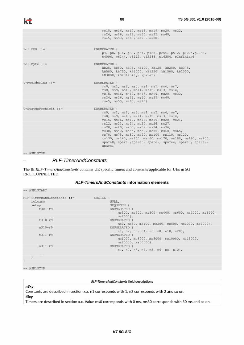
KT 5G-SIG
TS 5G.331 v1.0 (2016-08) 88
ms15, ms16, ms17, ms18, ms19, ms20, ms22,
ms24, ms26, ms28, ms30, ms35, ms40,
ms45, ms50, ms60, ms70, ms80}
PollPDU ::= ENUMERATED {
p4, p8, p16, p32, p64, p128, p256, p512, p1024,p2048,
p4096, p6144, p8192, p12288, p16384, pInfinity}
PollByte ::= ENUMERATED {
kB25, kB50, kB75, kB100, kB125, kB250, kB375,
kB500, kB750, kB1000, kB1250, kB1500, kB2000,
kB3000, kBinfinity, spare1}
T-Reordering ::= ENUMERATED {
ms0, ms1, ms2, ms3, ms4, ms5, ms6, ms7,
ms8, ms9, ms10, ms11, ms12, ms13, ms14,
ms15, ms16, ms17, ms18, ms19, ms20, ms22,
ms24, ms26, ms28, ms30, ms35, ms40,
ms45, ms50, ms60, ms70}
T-StatusProhibit ::= ENUMERATED {
ms0, ms1, ms2, ms3, ms4, ms5, ms6, ms7,
ms8, ms9, ms10, ms11, ms12, ms13, ms14,
ms15, ms16, ms17, ms18, ms19, ms20, ms21,
ms22, ms23, ms24, ms25, ms26, ms27,
ms28, ms29, ms30, ms32, ms34, ms36,
ms38, ms40, ms45, ms50, ms55, ms60, ms65,
ms70, ms75, ms80, ms90, ms100, ms110, ms120,
ms130, ms140, ms150, ms160, ms170, ms180, ms190, ms200,
spare8, spare7,spare6, spare5, spare4, spare3, spare2,
spare1}
-- ASN1STOP
– RLF-TimerAndConstants
The IE RLF-TimersAndConstants contains UE specific timers and constants applicable for UEs in 5G
RRC_CONNECTED.
RLF-TimersAndConstants information elements
-- ASN1START
RLF-TimersAndConstants ::= CHOICE {
release NULL,
setup SEQUENCE {
t301-r9 ENUMERATED {
ms100, ms200, ms300, ms400, ms600, ms1000, ms1500,
ms2000},
t310-r9 ENUMERATED {
ms0, ms50, ms100, ms200, ms500, ms1000, ms2000},
n310-r9 ENUMERATED {
n1, n2, n3, n4, n6, n8, n10, n20},
t311-r9 ENUMERATED {
ms1000, ms3000, ms5000, ms10000, ms15000,
ms20000, ms30000},
n311-r9 ENUMERATED {
n1, n2, n3, n4, n5, n6, n8, n10},
...
}
}
-- ASN1STOP
RLF-TimersAndConstants field descriptions
n3xy Constants are described in section x.x. n1 corresponds with 1, n2 corresponds with 2 and so on.
t3xy Timers are described in section x.x. Value ms0 corresponds with 0 ms, ms50 corresponds with 50 ms and so on.
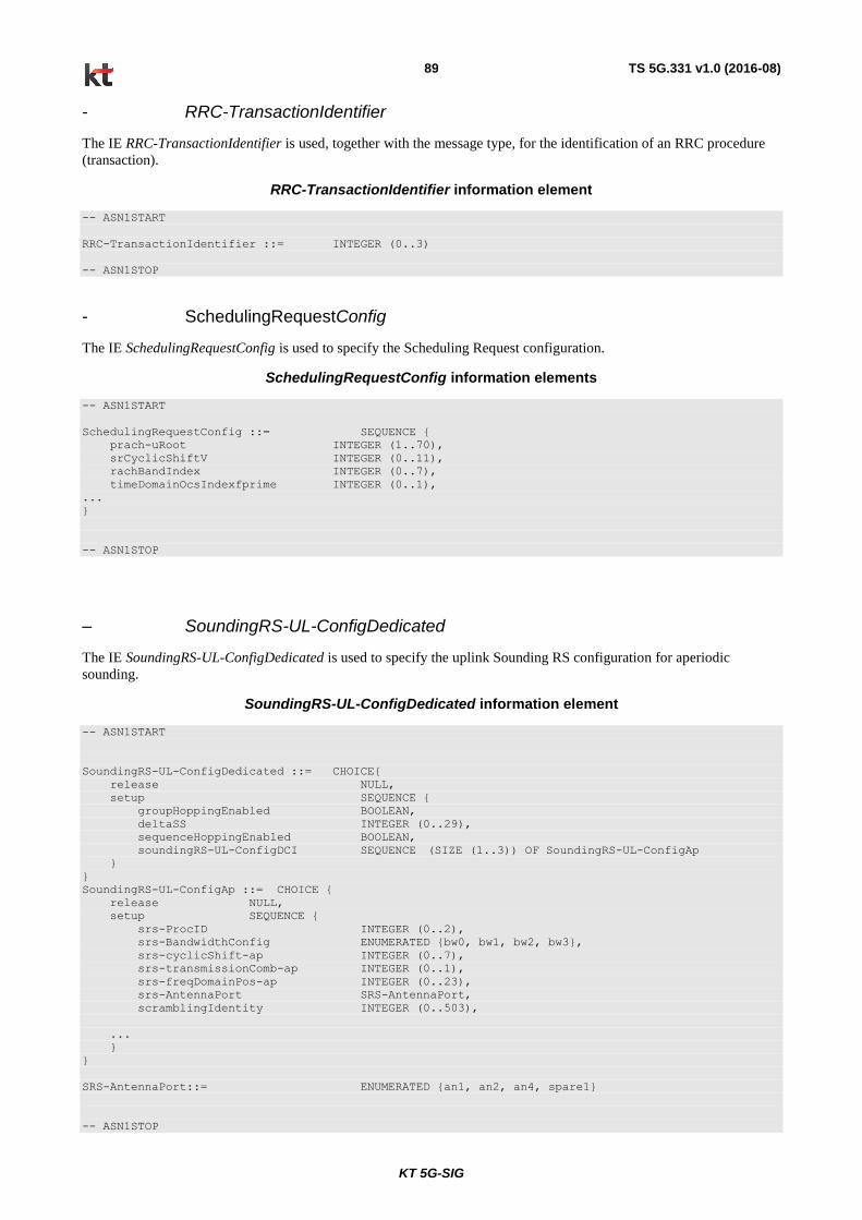
KT 5G-SIG
TS 5G.331 v1.0 (2016-08) 89
- RRC-TransactionIdentifier
The IE RRC-TransactionIdentifier is used, together with the message type, for the identification of an RRC procedure
(transaction).
RRC-TransactionIdentifier information element
-- ASN1START
RRC-TransactionIdentifier ::= INTEGER (0..3)
-- ASN1STOP
- SchedulingRequestConfig
The IE SchedulingRequestConfig is used to specify the Scheduling Request configuration.
SchedulingRequestConfig information elements
-- ASN1START
SchedulingRequestConfig ::= SEQUENCE {
prach-uRoot INTEGER (1..70),
srCyclicShiftV INTEGER (0..11),
rachBandIndex INTEGER (0..7),
timeDomainOcsIndexfprime INTEGER (0..1),
...
}
-- ASN1STOP
– SoundingRS-UL-ConfigDedicated
The IE SoundingRS-UL-ConfigDedicated is used to specify the uplink Sounding RS configuration for aperiodic
sounding.
SoundingRS-UL-ConfigDedicated information element
-- ASN1START
SoundingRS-UL-ConfigDedicated ::= CHOICE{
release NULL,
setup SEQUENCE {
groupHoppingEnabled BOOLEAN,
deltaSS INTEGER (0..29),
sequenceHoppingEnabled BOOLEAN,
soundingRS-UL-ConfigDCI SEQUENCE (SIZE (1..3)) OF SoundingRS-UL-ConfigAp
}
}
SoundingRS-UL-ConfigAp ::= CHOICE {
release NULL,
setup SEQUENCE {
srs-ProcID INTEGER (0..2),
srs-BandwidthConfig ENUMERATED {bw0, bw1, bw2, bw3},
srs-cyclicShift-ap INTEGER (0..7),
srs-transmissionComb-ap INTEGER (0..1),
srs-freqDomainPos-ap INTEGER (0..23),
srs-AntennaPort SRS-AntennaPort,
scramblingIdentity INTEGER (0..503),
...
}
}
SRS-AntennaPort::= ENUMERATED {an1, an2, an4, spare1}
-- ASN1STOP

KT 5G-SIG
TS 5G.331 v1.0 (2016-08) 90
– S-TMSI
The IE S-TMSI contains an S-Temporary Mobile Subscriber Identity, a temporary UE identity provided by the EPC
which uniquely identifies the UE within the tracking area.
S-TMSI information element
-- ASN1START
S-TMSI ::= SEQUENCE {
mmec MMEC,
m-TMSI BIT STRING (SIZE (32))
}
-- ASN1STOP
S-TMSI field descriptions
m-TMSI The first/leftmost bit of the bit string contains the most significant bit of the M-TMSI.
– TimeAlignmentTimer
The IE TimeAlignmentTimer is used to control how long the UE considers the serving cells belonging to the associated
TAG to be uplink time aligned. Corresponds to the Timer for time alignment in 5G.321 [6]. Value in number of sub-
frames. Value sf500 corresponds to 500 sub-frames, sf750 corresponds to 750 sub-frames and so on.
TimeAlignmentTimer information element
-- ASN1START
TimeAlignmentTimer ::= ENUMERATED {
sf500, sf750, sf1280, sf1920, sf2500, sf2560,f3750,
sf5120, sf6400, sf9600, sf10240, sf12800, sf25600,
sf51200,infinity, spare1}
-- ASN1STOP
– UplinkPowerControlCommon
The IE UplinkPowerControlCommon and IE UplinkPowerControlDedicated are used to specify parameters for uplink
power control in the system information and in the dedicated signalling, respectively.
UplinkPowerControlCommon information elements
-- ASN1START
UplinkPowerControlCommon ::= SEQUENCE {
p0-NominalPUSCH INTEGER (-126..24),
alpha ENUMERATED {al0, al04, al05, al06, al07, al08, al09, al1},
p0-NominalPUCCH INTEGER (-127..-96),
deltaFList-PUCCH DeltaFList-PUCCH,
deltaPreambleMsg3 INTEGER (-1..6)
}
DeltaFList-PUCCH ::= SEQUENCE {
deltaF-PUCCH-Format1 ENUMERATED {deltaF-2, deltaF0, deltaF2},
deltaF-PUCCH-Format1b ENUMERATED {deltaF1, deltaF3, deltaF5},
deltaF-PUCCH-Format2 ENUMERATED {deltaF-2, deltaF0, deltaF1, deltaF2},
...
}
-- ASN1STOP

KT 5G-SIG
TS 5G.331 v1.0 (2016-08) 91
UplinkPowerControlCommon field descriptions
alpha Parameter: α See TS 5G.213 [3, 6.1.1.1] where al0 corresponds to 0, al04 corresponds to value 0.4, al05 to 0.5, al06 to 0.6, al07 to 0.7, al08 to 0.8, al09 to 0.9 and al1 corresponds to 1.
deltaF-PUCCH-FormatX
Parameter: F_PUCCH ( )F for the PUCCH formats 1, 1b, 2. See TS 5G.213 [3, 6.1.2.1] where deltaF-2 corresponds
to -2 dB, deltaF0 corresponds to 0 dB and so on.
deltaPreambleMsg3
Parameter: 3_ MsgPREAMBLE see TS 5G.213 [3, 6.1.1.1]. Actual value = IE value * 2 [dB].
p0-NominalPUCCH
Parameter: PUCCH O_NOMINAL_P See TS 5G.213, 6.1.2.1, unit dBm.
p0-NominalPUSCH
Parameter: PUSCH O_NOMINAL_P See TS 5G.213, 6.1.1.1, unit dBm.
– UplinkPowerControlDedicated
UplinkPowerControlDedicated information elements
-- ASN1START
UplinkPowerControlDedicated ::= SEQUENCE {
p0-UE-PUSCH INTEGER (-8..7),
deltaMCS-Enabled ENUMERATED {en0, en1},
accumulationEnabled BOOLEAN,
p0-UE-PUCCH INTEGER (-8..7),
pSRS-Offset_ap INTEGER (0..15),
filterCoefficient FilterCoefficient,
...
}
-- ASN1STOP
UplinkPowerControlCommon and UplinkPowerControlDedicated field descriptions
accumulationEnabled
Parameter: Accumulation-enabled, see 5G.213 [3, 6.1.1.1]. TRUE corresponds to “enabled” whereas FALSE corresponds to “disabled”.
deltaMCS-Enabled
Parameter: Ks See 5G.213 [3, 6.1.1.1]. en0 corresponds to value 0 corresponding to state “disabled”. en1 corresponds to value 1.25 corresponding to “enabled”.
filterCoefficient
Specifies the filtering coefficient for RSRP measurements used to calculate path loss, as specified in 5G.213 [3, 6.1.1.1]. The same filtering mechanism applies as for quantityConfig described in 5.4.3.2.
p0-UE-PUCCH
Parameter: See 5G.213, 6.1.2.1, unit dBm.
p0-UE-PUSCH
Parameter: See 5G.213, 6.1.1.1, unit dBm.
pSPS-Offset
Parameter: pSRS-OFFSET for aperiodic sounding reference signal transmission. See 5G.213 [3, 6.1.3.1]. For Ks=1.25, the actual parameter value is pSRS-Offset value – 3. For Ks=0, the actual parameter value is -10.5 + 1.5*pSRS-Offset value.
PUCCHO_UE_ P
PUSCHO_UE_ P

KT 5G-SIG
TS 5G.331 v1.0 (2016-08) 92
6.3.3 Security control information elements
– NextHopChainingCount
The IE NextHopChainingCount is used to update the 5G KeNB key and corresponds to parameter NCC: See TS 33.401
[32, 7.2.8.4].
NextHopChainingCount information element
-- ASN1START
NextHopChainingCount ::= INTEGER (0..7)
-- ASN1STOP
– SecurityAlgorithmConfig
The IE SecurityAlgorithmConfig is used to configure AS integrity protection algorithm (SRBs) and AS ciphering
algorithm (SRBs and DRBs).
SecurityAlgorithmConfig information element
-- ASN1START
SecurityAlgorithmConfig ::= SEQUENCE {
cipheringAlgorithm ENUMERATED {
eea0, spare7, eea2, spare5, spare4, spare3,
spare2, spare1, ...},
integrityProtAlgorithm ENUMERATED {
eia0, spare7, eia2, spare5, spare4, spare3,
spare2, spare1, ...} OPTIONAL
}
-- ASN1STOP
SecurityAlgorithmConfig field descriptions
integrityProtAlgorithm Indicates the integrity protection algorithm to be used for SRBs, as specified in TS 33.401 [5.1.4.2], where eia0 is NULL and eia2 is AES algorithm.
cipheringAlgorithm Indicates the ciphering algorithm to be used for SRBs and DRBs, as specified in TS 33.401 [5.1.3.2], where eea0 is NULL and eea2 is AES algorithm.
– ShortMAC-I
The IE ShortMAC-I is used to identify and verify the UE at RRC connection re-establishment. The 16 least significant
bits of the MAC-I calculated using the security configuration of the source PCell, as specified in 5.3.7.4.
ShortMAC-I information element
-- ASN1START
ShortMAC-I ::= BIT STRING (SIZE (16))
-- ASN1STOP
– SecurityKeyConfig
The IE SecurityKeyConfig is used as the new 5G KeNB by the UE for deriving AS security keys upon 5G cell addition
and/or 5G cell change, as specified in 5.3.5.4.
SecurityKeyConfig information element
-- ASN1START
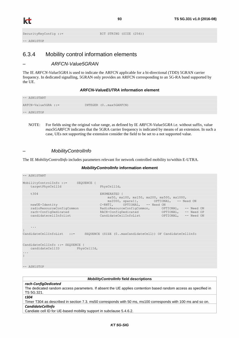
KT 5G-SIG
TS 5G.331 v1.0 (2016-08) 93
SecurityKeyConfig ::= BIT STRING (SIZE (256))
-- ASN1STOP
6.3.4 Mobility control information elements
– ARFCN-Value5GRAN
The IE ARFCN-Value5GRA is used to indicate the ARFCN applicable for a bi-directional (TDD) 5GRAN carrier
frequency. In dedicated signalling, 5GRAN only provides an ARFCN corresponding to an 5G-RA band supported by
the UE.
ARFCN-ValueEUTRA information element
-- ASN1START
ARFCN-Value5GRA ::= INTEGER (0..max5GARFCN)
-- ASN1STOP
NOTE: For fields using the original value range, as defined by IE ARFCN-Value5GRA i.e. without suffix, value
max5GARFCN indicates that the 5GRA carrier frequency is indicated by means of an extension. In such a
case, UEs not supporting the extension consider the field to be set to a not supported value.
– MobilityControlInfo
The IE MobilityControlInfo includes parameters relevant for network controlled mobility to/within E-UTRA.
MobilityControlInfo information element
-- ASN1START
MobilityControlInfo ::= SEQUENCE {
targetPhysCellId PhysCellId,
t304 ENUMERATED {
ms50, ms100, ms150, ms200, ms500, ms1000,
ms2000, spare1}, OPTIONAL, -- Need ON
newUE-Identity C-RNTI, OPTIONAL, -- Need ON
radioResourceConfigCommon RadioResourceConfigCommon, OPTIONAL, -- Need ON
rach-ConfigDedicated RACH-ConfigDedicated OPTIONAL, -- Need OP
candidatecellInfolist CandidateCellInfoList OPTIONAL, -- Need ON
...
}
CandidateCellInfoList ::= SEQUENCE (SIZE (0..maxCandidateCell)) OF CandidateCellInfo
CandidateCellInfo ::= SEQUENCE {
candidateCellID PhysCellId,
...
}
-- ASN1STOP
MobilityControlInfo field descriptions
rach-ConfigDedicated The dedicated random access parameters. If absent the UE applies contention based random access as specified in TS 5G.321.
t304 Timer T304 as described in section 7.3. ms50 corresponds with 50 ms, ms100 corresponds with 100 ms and so on.
CandidateCellInfo Candiate cell ID for UE-based mobility support in subclause 5.4.6.2.

KT 5G-SIG
TS 5G.331 v1.0 (2016-08) 94
– PhysCellId
The IE PhysCellId is used to indicate the physical layer identity of the cell, as defined in TS 5G.211 [21].
PhysCellId information element
-- ASN1START
PhysCellId ::= INTEGER (0..503)
-- ASN1STOP
– Q-OffsetRange
The IE Q-OffsetRange is used to indicate a cell or frequency specific offset to be applied when evaluating candidates for
cell re-selection or when evaluating triggering conditions for measurement reporting or for beam management. The
value in dB. Value dB-24 corresponds to -24 dB, dB-22 corresponds to -22 dB and so on.
Q- OffsetRange information element
-- ASN1START
Q-OffsetRange ::= ENUMERATED {
dB-24, dB-22, dB-20, dB-18, dB-16, dB-14,
dB-12, dB-10, dB-8, dB-6, dB-5, dB-4, dB-3,
dB-2, dB-1, dB0, dB1, dB2, dB3, dB4, dB5,
dB6, dB8, dB10, dB12, dB14, dB16, dB18,
dB20, dB22, dB24}
-- ASN1STOP
6.3.5 Measurement information elements
– CellIdentity
The IE CellIdentity is used to unambiguously identify a cell within a PLMN.
CellIdentity information element
-- ASN1START
CellIdentity ::= BIT STRING (SIZE (28))
-- ASN1STOP
– CellIndexList
The IE CellIndexList concerns a list of cell indices, which may be used for different purposes.
CellIndexList information element
-- ASN1START
CellIndexList ::= SEQUENCE (SIZE (1..maxCellMeas)) OF CellIndex
CellIndex ::= INTEGER (1..maxCellMeas)
-- ASN1STOP
– FilterCoefficient
The IE FilterCoefficient specifies the measurement filtering coefficient. Value fc0 corresponds to k = 0, fc1 corresponds
to k = 1, and so on.

KT 5G-SIG
TS 5G.331 v1.0 (2016-08) 95
FilterCoefficient information element
-- ASN1START
FilterCoefficient ::= ENUMERATED {
fc0, fc1, fc2, fc3, fc4, fc5,
fc6, fc7, fc8, fc9, fc11, fc13,
fc15, fc17, fc19, spare1, ...}
-- ASN1STOP
– Hysteresis
The IE Hysteresis is a parameter used within the entry and leave condition of an event triggered reporting condition.
The actual value is IE value * 0.5 dB.
Hysteresis information element
-- ASN1START
Hysteresis ::= INTEGER (0..30)
-- ASN1STOP
– MeasConfig
The IE MeasConfig specifies measurements to be performed by the UE, and covers intra-frequency mobility.
MeasConfig information element
-- ASN1START
MeasConfig ::= SEQUENCE {
-- Measurement objects
measObjectToRemoveList MeasObjectToRemoveList OPTIONAL, -- Need ON
measObjectToAddModList MeasObjectToAddModList OPTIONAL, -- Need ON
-- Reporting configurations
reportConfigToRemoveList ReportConfigToRemoveList OPTIONAL, -- Need ON
reportConfigToAddModList ReportConfigToAddModList OPTIONAL, -- Need ON
-- Measurement identities
measIdToRemoveList MeasIdToRemoveList OPTIONAL, -- Need ON
measIdToAddModList MeasIdToAddModList OPTIONAL, -- Need ON
-- Other parameters
quantityConfig QuantityConfig OPTIONAL, -- Need ON
s-Measure RSRP-Range OPTIONAL, -- Need ON
...
}
MeasIdToRemoveList ::= SEQUENCE (SIZE (1..maxMeasId)) OF MeasId
MeasObjectToRemoveList ::= SEQUENCE (SIZE (1..maxObjectId)) OF MeasObjectId
ReportConfigToRemoveList ::= SEQUENCE (SIZE (1..maxReportConfigId)) OF ReportConfigId
-- ASN1STOP

KT 5G-SIG
TS 5G.331 v1.0 (2016-08) 96
MeasConfig field descriptions
measObjectToRemoveList List of measurement objects to remove.
measObjectId Used to identify a measurement object configuration.
measObject Specifies measurement object configurations for 5GRAN measurements.
reportConfigToRemoveList List of measurement reporting configurations to remove.
reportConfigId Used to identify a measurement reporting configuration.
reportConfig Specifies measurement reporting configurations for 5GRAN measurements.
measIdToRemoveList
List of measurement identities to remove.
s-Measure Serving cell quality threshold controlling whether or not the UE is required to perform measurements of intra-frequency. Value “0” indicates to disable s-Measure.
– MeasId
The IE MeasId is used to identify a measurement configuration, i.e., linking of a measurement object and a reporting
configuration.
MeasId information element
-- ASN1START
MeasId ::= INTEGER (1..maxMeasId)
-- ASN1STOP
– MeasIdToAddModList
The IE MeasIdToAddModList concerns a list of measurement identities to add or modify, with for each entry the measId,
the associated measObjectId and the associated reportConfigId.
MeasIdToAddModList information element
-- ASN1START
MeasIdToAddModList ::= SEQUENCE (SIZE (1..maxMeasId)) OF MeasIdToAddMod
MeasIdToAddMod ::= SEQUENCE {
measId MeasId,
measObjectId MeasObjectId,
reportConfigId ReportConfigId
}
-- ASN1STOP
– MeasObject5GRAN
The IE MeasObject5GRAN specifies information applicable for intra-frequency 5GRAN neighbouring cells.
MeasObject5GRAN information element
-- ASN1START
MeasObject5GRAN ::= SEQUENCE {
carrierFreq ARFCN-Value5GRA,
offsetFreq Q-OffsetRange DEFAULT dB0,
-- Neighbour cell list
cellsToRemoveList CellIndexList OPTIONAL, -- Need ON
cellsToAddModList CellsToAddModList OPTIONAL, -- Need ON
t312 CHOICE {
release NULL,
setup ENUMERATED {ms0, ms50, ms100, ms200,

KT 5G-SIG
TS 5G.331 v1.0 (2016-08) 97
ms300, ms400, ms500, ms1000}
} OPTIONAL, -- Need ON
...
}
CellsToAddModList ::= SEQUENCE (SIZE (1..maxCellMeas)) OF CellsToAddMod
CellsToAddMod ::= SEQUENCE {
cellIndex INTEGER (1..maxCellMeas),
physCellId PhysCellId,
cellIndividualOffset Q-OffsetRange,
...
}
-- ASN1STOP
MeasObject5GRAN field descriptions
carrierFreq Identifies 5GRAN carrier frequency for which this configuration is valid.
offsetFreq
Offset value applicable to the carrier frequency. Value dB-24 corresponds to -24 dB, dB-22 corresponds to -22 dB and so on.
cellsToRemoveList
List of cells to remove from the neighbouring cell list.
cellsToAddModList List of cells to add/ modify in the neighbouring cell list.
cellIndex Entry index in the neighbouring cell list. An entry may concern a range of cells, in which case this value applies to the entire range.
physCellId Physical cell identity of a cell in neighbouring cell list.
cellIndividualOffset Cell individual offset applicable to a specific neighbouring cell. Value dB-24 corresponds to -24 dB, dB-22 corresponds to -22 dB and so on.
t312 The value of timer T312 which can be configured to UEs in a standalone mode. Value ms0 represents 0 ms, ms50 represents 50 ms and so on.
– MeasObjectId
The IE MeasObjectId used to identify a measurement object configuration.
MeasObjectId information element
-- ASN1START
MeasObjectId ::= INTEGER (1..maxObjectId)
-- ASN1STOP
– MeasObjectToAddModList
The IE MeasObjectToAddModList concerns a list of measurement objects to add or modify
MeasObjectToAddModList information element
-- ASN1START
MeasObjectToAddModList ::= SEQUENCE (SIZE (1..maxObjectId)) OF MeasObjectToAddMod
MeasObjectToAddMod ::= SEQUENCE {
measObjectId MeasObjectId,
measObject CHOICE {
measObject5GRAN MeasObject5GRAN,
...
}

KT 5G-SIG
TS 5G.331 v1.0 (2016-08) 98
}
-- ASN1STOP
– MeasResults
The IE MeasResults covers measured results for intra-frequency, mobility.
MeasResults information element
-- ASN1START
MeasResults ::= SEQUENCE {
measId MeasId,
measResultPCell BeamMeasResultList,
measResultNeighCells MeasResultList5GRA OPTIONAL,
measResultServFreqList MeasResultServFreqList OPTIONAL,
...
}
MeasResultList5GRA ::= SEQUENCE (SIZE (1..maxCellReport)) OF MeasResult5GRA
MeasResult5GRA ::= SEQUENCE {
physCellId PhysCellId,
measResult BeamMeasResultList OPTIONAL,
...
}
MeasResultServFreqList ::= SEQUENCE (SIZE (1..maxServCell)) OF MeasResultServFreq
MeasResultServFreq ::= SEQUENCE {
servFreqId ServCellIndex,
measResultSCell BeamMeasResultList OPTIONAL,
measResultBestNeighCell SEQUENCE {
physCellId PhysCellId,
resultNCell BeamMeasResultList
} OPTIONAL,
...
}
PLMN-IdentityList2 ::= SEQUENCE (SIZE (1..5)) OF PLMN-Identity
BeamMeasResultList ::= SEQUENCE (SIZE (1..maxBeamCount)) OF BeamMeasResult
RsrpResultList ::= SEQUENCE (SIZE (1..maxUERXBeamCount)) OF RSRP-Range
BeamMeasResult ::= SEQUENCE {
beamID INTEGER (0..511),
rsrpResult RSRP-Range,
rsrpResultList RsrpResultList OPTIONAL,
...
}
-- ASN1STOP

KT 5G-SIG
TS 5G.331 v1.0 (2016-08) 99
MeasResults field descriptions
measId Identifies the measurement identity for which the reporting is being performed.
measResultPCell Measured result of the PCell.
measResultList5GRA List of measured results for the maximum number of reported best cells for a 5GRAN measurement identity.
rsrpResult Measured RSRP result of a 5GRAN cell. The rsrpResult is only reported if configured by the 5GNB.
measResult
Measured result of an 5GRAN cell. The rsrpResult is only reported if configured by the 5GNB
MeasResultServFreqList Measured results of the serving frequencies: the measurement result of each SCell, if any, and of the best neighbouring cell on each serving frequency
beamIndex Locigal beam index i=0,…,8∙P∙N_symb^DL-1 as specified in 5G.211 6.7.4.3
rsrpResultList
List measured RSRP result of UE RX beams
maxBeamCount
Maximum number of 5GNB beams to be reported in the measurement report
maxUERXBeamCount
Maximum number of RSRPs of UE beams for a reported 5GNB beam
.
– MMEC
The IE MMEC identifies an MME within the scope of an MME Group within a PLMN.
MMEC information element
-- ASN1START
MMEC ::= BIT STRING (SIZE (8))
-- ASN1STOP
– PLMN-Identity
The IE PLMN-Identity identifies a Public Land Mobile Network. Further information regarding how to set the IE are
specified in TS 23.003.
PLMN-Identity information element
-- ASN1START
PLMN-Identity ::= SEQUENCE {
mcc MCC OPTIONAL, -- Cond MCC
mnc MNC
}
MCC ::= SEQUENCE (SIZE (3)) OF
MCC-MNC-Digit
MNC ::= SEQUENCE (SIZE (2..3)) OF
MCC-MNC-Digit
MCC-MNC-Digit ::= INTEGER (0..9)
-- ASN1STOP
– RSRP-Range
The IE RSRP-Range specifies the value range used in RSRP measurements and thresholds. Integer value for RSRP
measurements according to the mapping table in table 6.3.5-1.
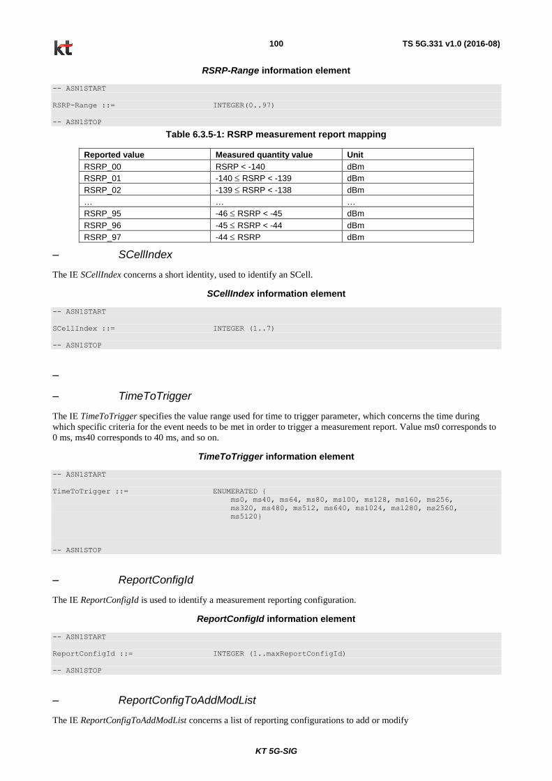
KT 5G-SIG
TS 5G.331 v1.0 (2016-08) 100
RSRP-Range information element
-- ASN1START
RSRP-Range ::= INTEGER(0..97)
-- ASN1STOP
Table 6.3.5-1: RSRP measurement report mapping
Reported value Measured quantity value Unit
RSRP_00 RSRP < -140 dBm
RSRP_01 -140 RSRP < -139 dBm
RSRP_02 -139 RSRP < -138 dBm
… … …
RSRP_95 -46 RSRP < -45 dBm
RSRP_96 -45 RSRP < -44 dBm
RSRP_97 -44 RSRP dBm
– SCellIndex
The IE SCellIndex concerns a short identity, used to identify an SCell.
SCellIndex information element
-- ASN1START
SCellIndex ::= INTEGER (1..7)
-- ASN1STOP
–
– TimeToTrigger
The IE TimeToTrigger specifies the value range used for time to trigger parameter, which concerns the time during
which specific criteria for the event needs to be met in order to trigger a measurement report. Value ms0 corresponds to
0 ms, ms40 corresponds to 40 ms, and so on.
TimeToTrigger information element
-- ASN1START
TimeToTrigger ::= ENUMERATED {
ms0, ms40, ms64, ms80, ms100, ms128, ms160, ms256,
ms320, ms480, ms512, ms640, ms1024, ms1280, ms2560,
ms5120}
-- ASN1STOP
– ReportConfigId
The IE ReportConfigId is used to identify a measurement reporting configuration.
ReportConfigId information element
-- ASN1START
ReportConfigId ::= INTEGER (1..maxReportConfigId)
-- ASN1STOP
– ReportConfigToAddModList
The IE ReportConfigToAddModList concerns a list of reporting configurations to add or modify
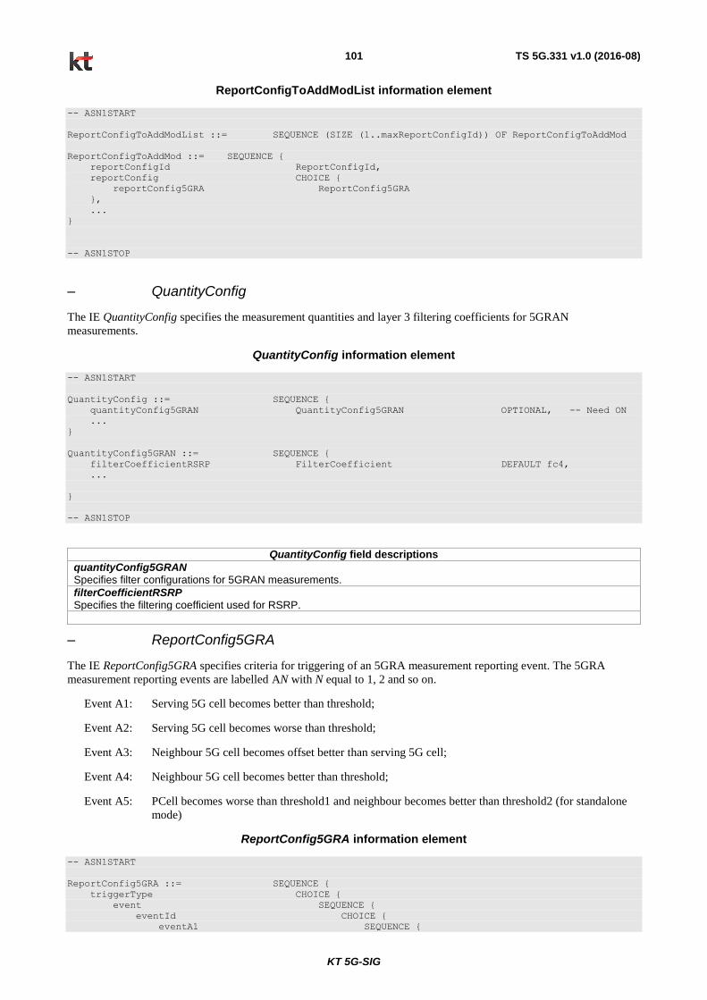
KT 5G-SIG
TS 5G.331 v1.0 (2016-08) 101
ReportConfigToAddModList information element
-- ASN1START
ReportConfigToAddModList ::= SEQUENCE (SIZE (1..maxReportConfigId)) OF ReportConfigToAddMod
ReportConfigToAddMod ::= SEQUENCE {
reportConfigId ReportConfigId,
reportConfig CHOICE {
reportConfig5GRA ReportConfig5GRA
},
...
}
-- ASN1STOP
– QuantityConfig
The IE QuantityConfig specifies the measurement quantities and layer 3 filtering coefficients for 5GRAN
measurements.
QuantityConfig information element
-- ASN1START
QuantityConfig ::= SEQUENCE {
quantityConfig5GRAN QuantityConfig5GRAN OPTIONAL, -- Need ON
...
}
QuantityConfig5GRAN ::= SEQUENCE {
filterCoefficientRSRP FilterCoefficient DEFAULT fc4,
...
}
-- ASN1STOP
QuantityConfig field descriptions
quantityConfig5GRAN Specifies filter configurations for 5GRAN measurements.
filterCoefficientRSRP Specifies the filtering coefficient used for RSRP.
– ReportConfig5GRA
The IE ReportConfig5GRA specifies criteria for triggering of an 5GRA measurement reporting event. The 5GRA
measurement reporting events are labelled AN with N equal to 1, 2 and so on.
Event A1: Serving 5G cell becomes better than threshold;
Event A2: Serving 5G cell becomes worse than threshold;
Event A3: Neighbour 5G cell becomes offset better than serving 5G cell;
Event A4: Neighbour 5G cell becomes better than threshold;
Event A5: PCell becomes worse than threshold1 and neighbour becomes better than threshold2 (for standalone
mode)
ReportConfig5GRA information element
-- ASN1START
ReportConfig5GRA ::= SEQUENCE {
triggerType CHOICE {
event SEQUENCE {
eventId CHOICE {
eventA1 SEQUENCE {

KT 5G-SIG
TS 5G.331 v1.0 (2016-08) 102
a1-Threshold Threshold5GRA,
reportForMobility BOOLEAN
},
eventA2 SEQUENCE {
a2-Threshold Threshold5GRA,
reportForMobility BOOLEAN
},
eventA3 SEQUENCE {
a3-Offset INTEGER (-30..30),
reportOnLeave BOOLEAN,
reportForMobility BOOLEAN
},
eventA4 SEQUENCE {
a4-Threshold Threshold5GRA,
reportForMobility BOOLEAN
},
eventA5 SEQUENCE {
a5-Threshold1 Threshold5GRA,
a5-Threshold2 Threshold5GRA,
reportForMobility BOOLEAN
}
},
hysteresis Hysteresis,
timeToTrigger TimeToTrigger
},
periodical SEQUENCE {
purpose ENUMERATED {reportStrongestCells}
}
},
maxReportCells INTEGER (1..maxCellReport),
reportInterval ReportInterval,
reportAmount ENUMERATED {r1, r2, r4, r8, r16, r32, r64, infinity},
reportAddNeighMeas ENUMERATED {setup} OPTIONAL, -- Need OR
useT312 BOOLEAN OPTIONAL, -- Need ON
...
}
Threshold5GRA ::= CHOICE{
threshold-RSRP RSRP-Range,
...
}
-- ASN1STOP
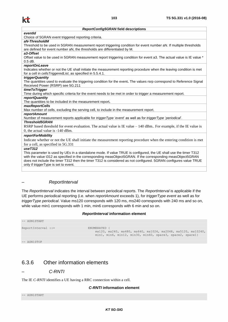
KT 5G-SIG
TS 5G.331 v1.0 (2016-08) 103
ReportConfig5GRAN field descriptions
eventId Choice of 5GRAN event triggered reporting criteria.
aN-ThresholdM Threshold to be used in 5GRAN measurement report triggering condition for event number aN. If multiple thresholds are defined for event number aN, the thresholds are differentiated by M.
a3-Offset Offset value to be used in 5GRAN measurement report triggering condition for event a3. The actual value is IE value * 0.5 dB.
reportOnLeave Indicates whether or not the UE shall initiate the measurement reporting procedure when the leaving condition is met for a cell in cellsTriggeredList, as specified in 5.5.4.1.
triggerQuantity The quantities used to evaluate the triggering condition for the event. The values rsrp correspond to Reference Signal Received Power (RSRP) see 5G.211
timeToTrigger Time during which specific criteria for the event needs to be met in order to trigger a measurement report.
reportQuantity The quantities to be included in the measurement report.
maxReportCells Max number of cells, excluding the serving cell, to include in the measurement report.
reportAmount Number of measurement reports applicable for triggerType ‘event’ as well as for triggerType ‘periodical’.
Threshold5GRAN
RSRP based threshold for event evaluation. The actual value is IE value – 140 dBm.. For example, if the IE value is
0, the actual value is -140 dBm.
reportForMobility Indicate whether or not the UE shall initiate the measurement reporting procedure when the entering condition is met
for a cell, as specified in 5G.331
useT312 This parameter is used by UEs in a standalone mode. If value TRUE is configured, the UE shall use the timer T312 with the value t312 as specified in the corresponding measObject5GRAN. If the corresponding measObject5GRAN does not include the timer T312 then the timer T312 is considered as not configured. 5GRAN configures value TRUE only if triggerType is set to event.
– ReportInterval
The ReportInterval indicates the interval between periodical reports. The ReportInterval is applicable if the
UE performs periodical reporting (i.e. when reportAmount exceeds 1), for triggerType event as well as for
triggerType periodical. Value ms120 corresponds with 120 ms, ms240 corresponds with 240 ms and so on,
while value min1 corresponds with 1 min, min6 corresponds with 6 min and so on.
ReportInterval information element
-- ASN1START
ReportInterval ::= ENUMERATED {
ms120, ms240, ms480, ms640, ms1024, ms2048, ms5120, ms10240,
min1, min6, min12, min30, min60, spare3, spare2, spare1}
-- ASN1STOP
6.3.6 Other information elements
– C-RNTI
The IE C-RNTI identifies a UE having a RRC connection within a cell.
C-RNTI information element
-- ASN1START

KT 5G-SIG
TS 5G.331 v1.0 (2016-08) 104
C-RNTI ::= BIT STRING (SIZE (16))
-- ASN1STOP
– UE-CapabilityRAT-ContainerList
The IE UE-CapabilityRAT-ContainerList contains list of containers, one for each RAT for which UE capabilities are
transferred, if any.
UE-CapabilityRAT-ContainerList information element
-- ASN1START
UE-CapabilityRAT-ContainerList ::=SEQUENCE (SIZE (0..maxRAT-Capabilities)) OF UE-CapabilityRAT-
Container
UE-CapabilityRAT-Container ::= SEQUENCE {
rat-Type RAT-Type,
ueCapabilityRAT-Container OCTET STRING
}
-- ASN1STOP
UECapabilityRAT-ContainerList field descriptions
ueCapabilityRAT-Container Container for the UE capabilities of the indicated RAT. The encoding is defined in the specification of each RAT: For 5G-RA: the encoding of UE capabilities is defined in IE UE-5GRA-Capability.
– UE-5GRA-Capability
The IE UE-5GRA-Capability is used to convey the 5G UE Radio Access Capability Parameters.
UE-5GRA-Capability information element
-- ASN1START
UE-5GRA-Capability ::= SEQUENCE {
accessStratumRelease AccessStratumRelease,
ueCapabilityFEC BOOLEAN,
phyLayerParameters PhyLayerParameters,
rf-Parameters RF-Parameters,
nonCriticalExtension UE-5GRA-Capability-v1-IEs OPTIONAL
}
UE-5GRA-Capability-v1-IEs ::= SEQUENCE {
lateNonCriticalExtension OCTET STRING OPTIONAL,
nonCriticalExtension SEQUENCE {} OPTIONAL
}
AccessStratumRelease ::= ENUMERATED {
rel1, spare7, spare6, spare5, spare4, spare3,
spare2, spare1, ...}
PhyLayerParameters ::= SEQUENCE {
twoAntennaPortsForPUCCH ENUMERATED {supported} OPTIONAL,
twoAntennaPortsForPUSCH ENUMERATED {supported} OPTIONAL,
...
}
RF-Parameters ::= SEQUENCE {
supportedBandList5GRA SupportedBandList5GRA,
supportedBandCombination SupportedBandCombination
}
SupportedBandList5GRA ::= SEQUENCE (SIZE (1..maxBands)) OF SupportedBand5GRA
SupportedBand5GRA ::= SEQUENCE {
band5GRA INTEGER (1..64)
}
SupportedBandCombination ::= SEQUENCE (SIZE (1..maxBandComb)) OF BandCombinationParameters
BandCombinationParameters ::= SEQUENCE (SIZE (1..maxSimultaneousBands)) OF BandParameters
BandParameters ::= SEQUENCE {

KT 5G-SIG
TS 5G.331 v1.0 (2016-08) 105
band5GRA INTEGER (1..64),
bandParametersUL BandParametersUL OPTIONAL,
bandParametersDL BandParametersDL OPTIONAL
}
BandParametersUL ::= SEQUENCE (SIZE (1..maxBandwidthClass)) OF CA-MIMO-ParametersUL
CA-MIMO-ParametersUL ::= SEQUENCE {
ca-BandwidthClassUL CA-BandwidthClass,
numberOffCarriers INTEGER(1..8),
supportedMIMO-CapabilityUL MIMO-CapabilityUL OPTIONAL
}
BandParametersDL ::= SEQUENCE (SIZE (1..maxBandwidthClass)) OF CA-MIMO-ParametersDL
CA-MIMO-ParametersDL ::= SEQUENCE {
ca-BandwidthClassDL CA-BandwidthClass,
numberOffCarriers INTEGER(1..8),
supportedMIMO-CapabilityDL MIMO-CapabilityDL OPTIONAL
}
CA-BandwidthClass ::= ENUMERATED {a, b, c, d, e, f, ...}
MIMO-CapabilityUL ::= ENUMERATED {oneLayer, twoLayers }
MIMO-CapabilityDL ::= ENUMERATED {oneLayer, twoLayers }
-- ASN1STOP
UE-5GRA-Capability information element
ueCapabilityFEC Indicates the UE capability to support turbro code.
numberOfUEbeam indicates how many TX(RX) beam the UE can make
bandCombinationList5GRA One entry corresponding to each supported band combination listed in the same order as in supportedBandCombination.
Band5GRA 5GRA band as defined in TS 36.101[x].
bandList5GRA One entry corresponding to each supported 5GRA band listed in the same order as in supportedBandList5GRA. This field shall include all bands which are indicated in BandCombinationParameters.
CA-BandwidthClass The CA bandwidth class supported by the UE as defined in TS 36.101[x].
MIMO-CapabilityDL The number of supported layers for spatial multiplexing in DL.
MIMO-CapabilityUL The number of supported layers for spatial multiplexing in UL.
SupportedBandCombinationExt Each entry corresponds to the band combination listed in the same order as in supportedBandCombination.
supportedBandwidthCombinationSet Field encoded as a bit map, where bit N is set to "1" if UE support Bandwidth Combination Set N for this band combination, see 36.133 [42]. The leading / leftmost bit (bit 0) corresponds to the Bandwidth Combination Set 0, the next bit corresponds to the Bandwidth Combination Set 1 and so on. The UE shall neither include the field for a non-CA band combination, nor for a CA band combination for which the UE only supports Bandwidth Combination Set 0. twoAntennaPortsForPUCCH twoAntennaPortsForPUSCH
– RAT-Type
The IE RAT-Type is used to indicate the radio access technology (RAT), including 5G-RA, of the requested/ transferred
UE capabilities.
RAT-Type information element
-- ASN1START

KT 5G-SIG
TS 5G.331 v1.0 (2016-08) 106
RAT-Type ::= ENUMERATED {
fivegra, spare7, spare6, spare5, spare4,
spare3, spare2, spare1, ...}
-- ASN1STOP
– UE-TimersAndConstants
The IE UE-TimersAndConstants contains timers and constants used by the UE in either RRC_CONNECTED or
RRC_IDLE in standalone mode
6.4 RRC multiplicity and type constraint values
– Multiplicity and type constraint definitions
-- ASN1START
maxDRB INTEGER ::= 11 -- Maximum number of Data Radio Bearers
maxMeasId INTEGER ::= 32
maxRAT-Capabilities INTEGER ::= 8 -- Maximum number of interworking RATs (incl 5GRA)
ServCellIndex ::= INTEGER (0..7)
ARFCN-Value5GRA ::= INTEGER (0..max5GARFCN)
maxBandwidthClass INTEGER ::= 16 -- Maximum number of supported CA BW classes per band
maxBands INTEGER ::= 16 -- Maximum number of bands listed in UE caps
maxSimultaneousBands INTEGER ::= 16 -- Maximum number of simultaneously aggregated bands
maxBandComb INTEGER ::= 64 -- Maximum number of band combinations.
maxCandidateCell INTEGER ::= 8
maxSCell INTEGER ::= 7 -- Maximum number of SCells
max5GARFCN INTEGER ::= 262143 -- Maximum value of 5GRAN carrier frequency
maxCellReport INTEGER ::= 8 -- Maximum number of reported cells
maxCellMeas INTEGER ::= 32 -- Maximum number of entries in each of the
-- cell lists in a measurement object
maxObjectId INTEGER ::= 32
maxPLMN INTEGER ::= 6 -- Maximum number of PLMNs
maxReportConfigId INTEGER ::= 32
maxServCell INTEGER ::= 8 -- Maximum number of Serving cells
maxBeamCount INTEGER ::= 8 -- Maximum number of 5GNB beams to be reported
-- in the measurement report
maxUERXBeamCount INTEGER ::= 4 -- Maximum number of RSRPs of UE beams for a reported
-- 5GNB beam
-- ASN1STOP
– End of 5GRA-RRC-Definitions
-- ASN1START
END
-- ASN1STOP
7 Variables and constants
7.1 UE variables
NOTE: To facilitate the specification of the UE behavioural requirements, UE variables are represented using
ASN.1. Unless explicitly specified otherwise, it is however up to UE implementation how to store the
variables. The optionality of the IEs in ASN.1 is used only to indicate that the values may not always be
available.
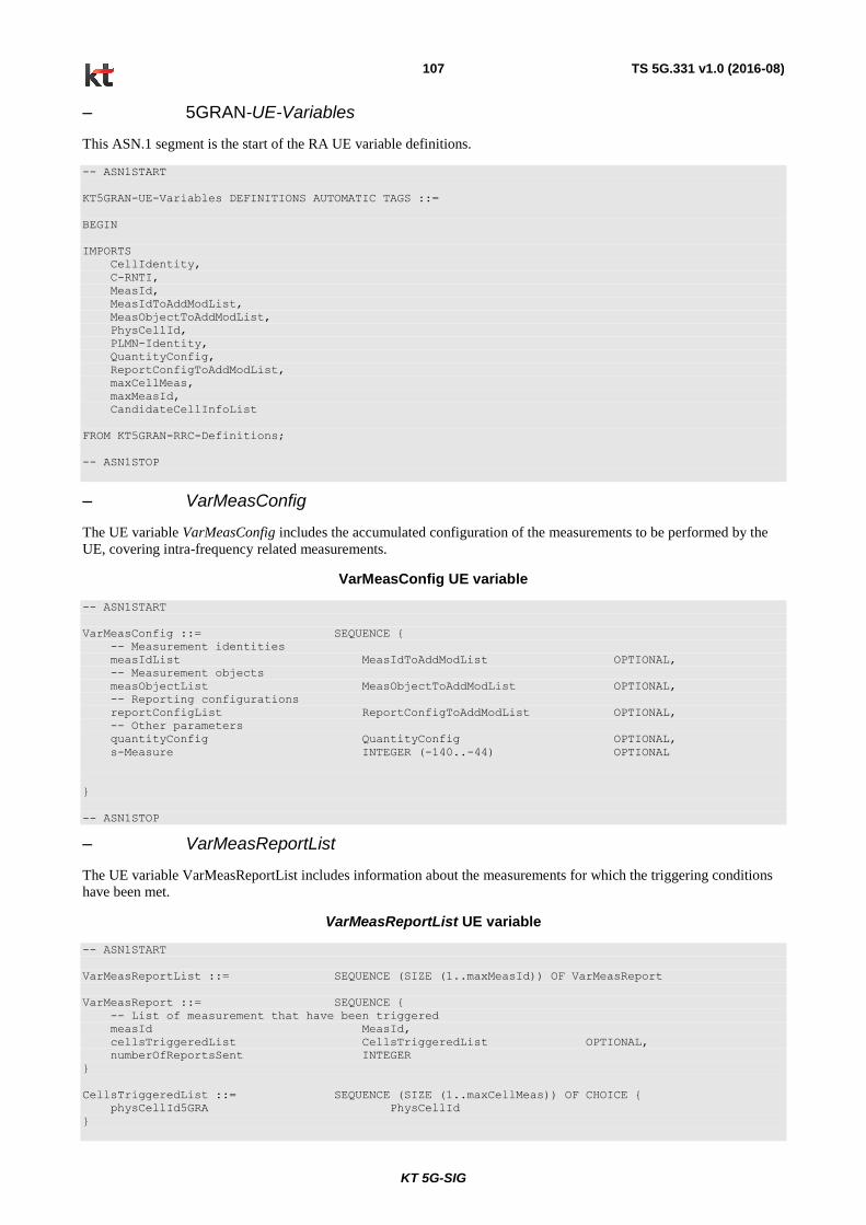
KT 5G-SIG
TS 5G.331 v1.0 (2016-08) 107
– 5GRAN-UE-Variables
This ASN.1 segment is the start of the RA UE variable definitions.
-- ASN1START
KT5GRAN-UE-Variables DEFINITIONS AUTOMATIC TAGS ::=
BEGIN
IMPORTS
CellIdentity,
C-RNTI,
MeasId,
MeasIdToAddModList,
MeasObjectToAddModList,
PhysCellId,
PLMN-Identity,
QuantityConfig,
ReportConfigToAddModList,
maxCellMeas,
maxMeasId,
CandidateCellInfoList
FROM KT5GRAN-RRC-Definitions;
-- ASN1STOP
– VarMeasConfig
The UE variable VarMeasConfig includes the accumulated configuration of the measurements to be performed by the
UE, covering intra-frequency related measurements.
VarMeasConfig UE variable
-- ASN1START
VarMeasConfig ::= SEQUENCE {
-- Measurement identities
measIdList MeasIdToAddModList OPTIONAL,
-- Measurement objects
measObjectList MeasObjectToAddModList OPTIONAL,
-- Reporting configurations
reportConfigList ReportConfigToAddModList OPTIONAL,
-- Other parameters
quantityConfig QuantityConfig OPTIONAL,
s-Measure INTEGER (-140..-44) OPTIONAL
}
-- ASN1STOP
– VarMeasReportList
The UE variable VarMeasReportList includes information about the measurements for which the triggering conditions
have been met.
VarMeasReportList UE variable
-- ASN1START
VarMeasReportList ::= SEQUENCE (SIZE (1..maxMeasId)) OF VarMeasReport
VarMeasReport ::= SEQUENCE {
-- List of measurement that have been triggered
measId MeasId,
cellsTriggeredList CellsTriggeredList OPTIONAL,
numberOfReportsSent INTEGER
}
CellsTriggeredList ::= SEQUENCE (SIZE (1..maxCellMeas)) OF CHOICE {
physCellId5GRA PhysCellId
}
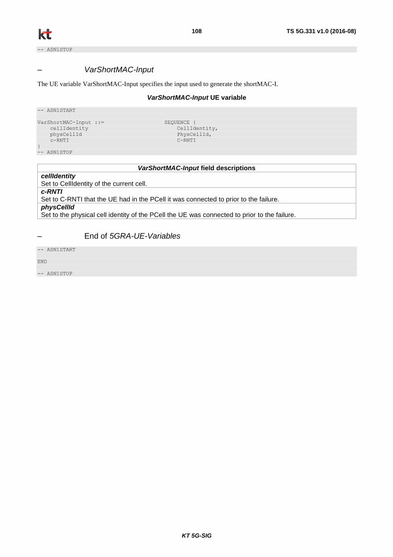
KT 5G-SIG
TS 5G.331 v1.0 (2016-08) 108
-- ASN1STOP
– VarShortMAC-Input
The UE variable VarShortMAC-Input specifies the input used to generate the shortMAC-I.
VarShortMAC-Input UE variable
-- ASN1START
VarShortMAC-Input ::= SEQUENCE {
cellIdentity CellIdentity,
physCellId PhysCellId,
c-RNTI C-RNTI
}
-- ASN1STOP
VarShortMAC-Input field descriptions
cellIdentity Set to CellIdentity of the current cell.
c-RNTI Set to C-RNTI that the UE had in the PCell it was connected to prior to the failure.
physCellId Set to the physical cell identity of the PCell the UE was connected to prior to the failure.
– End of 5GRA-UE-Variables
-- ASN1START
END
-- ASN1STOP
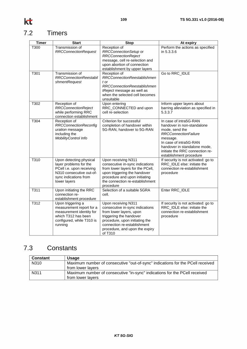
KT 5G-SIG
TS 5G.331 v1.0 (2016-08) 109
7.2 Timers
Timer Start Stop At expiry
T300
Transmission of RRCConnectionRequest
Reception of RRCConnectionSetup or RRCConnectionReject
message, cell re-selection and upon abortion of connection establishment by upper layers
Perform the actions as specified in 5.3.3.6
T301 Transmission of RRCConnectionReestabilshmentRequest
Reception of RRCConnectionReestablishment or RRCConnectionReestablishmentReject message as well as
when the selected cell becomes unsuitable
Go to RRC_IDLE
T302 Reception of RRCConnectionReject while performing RRC connection establishment
Upon entering RRC_CONNECTED and upon cell re-selection
Inform upper layers about barring alleviation as specified in 5.3.3.7
T304 Reception of RRCConnectionReconfiguration message including the MobilityControl Info
Criterion for successful completion of handover within 5G-RAN, handover to 5G-RAN
In case of intra5G-RAN handover in non-standalone mode, send the RRCConnectionFailure message. In case of intra5G-RAN handover in standalone mode, initiate the RRC connection re-establishment procedure
T310 Upon detecting physical layer problems for the PCell i.e. upon receiving N310 consecutive out-of-sync indications from lower layers
Upon receiving N311 consecutive in-sync indications from lower layers for the PCell, upon triggering the handover procedure and upon initiating the connection re-establishment procedure
If security is not activated: go to RRC_IDLE else: initiate the connection re-establishment procedure
T311 Upon initiating the RRC connection re-establishment procedure
Selection of a suitable 5GRA cell.
Enter RRC_IDLE
T312 Upon triggering a measurement report for a measurement identity for which T312 has been configured, while T310 is running
Upon receiving N311 consecutive in-sync indications from lower layers, upon triggering the handover procedure, upon initiating the connection re-establishment procedure, and upon the expiry of T310
If security is not activated: go to RRC_IDLE else: initiate the connection re-establishment procedure
7.3 Constants
Constant Usage
N310 Maximum number of consecutive "out-of-sync" indications for the PCell received from lower layers
N311 Maximum number of consecutive "in-sync" indications for the PCell received from lower layers
KT 5G-SIG
TS 5G.331 v1.0 (2016-08) 110
8 Protocol data unit abstract syntax
8.1 General
The RRC PDU contents in clause 6 and clause 10 are described using abstract syntax notation one (ASN.1) as specified
in ITU-T Rec. X.680 [13] and X.681 [14]. Transfer syntax for RRC PDUs is derived from their ASN.1 definitions by
use of Packed Encoding Rules, unaligned as specified in ITU-T Rec. X.691 [15].
The following encoding rules apply in addition to what has been specified in X.691:
- When a bit string value is placed in a bit-field as specified in 15.6 to 15.11 in X.691, the leading bit of the bit
string value shall be placed in the leading bit of the bit-field, and the trailing bit of the bit string value shall be
placed in the trailing bit of the bit-field.
NOTE: The terms 'leading bit' and 'trailing bit' are defined in ITU-T Rec. X.680. When using the 'bstring' notation,
the leading bit of the bit string value is on the left, and the trailing bit of the bit string value is on the right.
- When decoding types constrained with the ASN.1 Contents Constraint ("CONTAINING"), automatic decoding
of the contained type should not be performed because errors in the decoding of the contained type should not
cause the decoding of the entire RRC message PDU to fail. It is recommended that the decoder first decodes the
outer PDU type that contains the OCTET STRING or BIT STRING with the Contents Constraint, and then
decodes the contained type that is nested within the OCTET STRING or BIT STRING as a separate step.
- When decoding a) RRC message PDUs, b) BIT STRING constrained with a Contents Constraint, or c) OCTET
STRING constrained with a Contents Constraint, PER decoders are required to never report an error if there are
extraneous zero or non-zero bits at the end of the encoded RRC message PDU, BIT STRING or OCTET
STRING.
8.2 Structure of encoded RRC messages
An RRC PDU, which is the bit string that is exchanged between peer entities/ across the radio interface contains the
basic production as defined in X.691.
RRC PDUs shall be mapped to and from PDCP SDUs (in case of DCCH) or RLC SDUs (in case of PCCH, BCCH,
CCCH or MCCH) upon transmission and reception as follows:
- when delivering an RRC PDU as an PDCP SDU to the PDCP layer for transmission, the first bit of the RRC
PDU shall be represented as the first bit in the PDCP SDU and onwards; and
- when delivering an RRC PDU as an RLC SDU to the RLC layer for transmission, the first bit of the RRC PDU
shall be represented as the first bit in the RLC SDU and onwards; and
- upon reception of an PDCP SDU from the PDCP layer, the first bit of the PDCP SDU shall represent the first bit
of the RRC PDU and onwards; and
- upon reception of an RLC SDU from the RLC layer, the first bit of the RLC SDU shall represent the first bit of
the RRC PDU and onwards.
8.3 Basic production
The 'basic production' is obtained by applying UNALIGNED PER to the abstract syntax value (the ASN.1 description)
as specified in X.691. It always contains a multiple of 8 bits.
8.4 Extension
The following rules apply with respect to the use of protocol extensions:
- A transmitter compliant with this version of the specification shall, unless explicitly indicated otherwise on a
PDU type basis, set the extension part empty. Transmitters compliant with a later version may send non-empty
extensions;
- A transmitter compliant with this version of the specification shall set spare bits to zero;
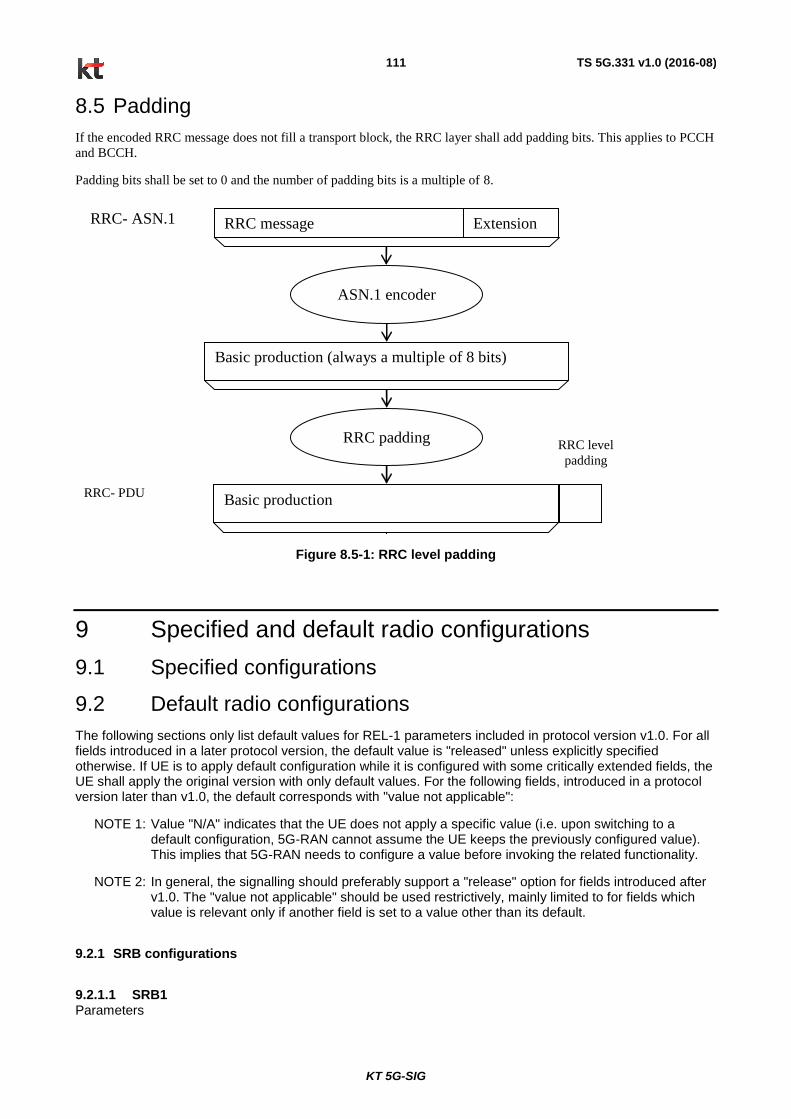
KT 5G-SIG
TS 5G.331 v1.0 (2016-08) 111
8.5 Padding
If the encoded RRC message does not fill a transport block, the RRC layer shall add padding bits. This applies to PCCH
and BCCH.
Padding bits shall be set to 0 and the number of padding bits is a multiple of 8.
RRC padding RRC level
padding
ASN.1 encoder
Basic production
Basic production (always a multiple of 8 bits)
RRC message
RRC- PDU
Extension RRC- ASN.1
Figure 8.5-1: RRC level padding
9 Specified and default radio configurations
9.1 Specified configurations
9.2 Default radio configurations
The following sections only list default values for REL-1 parameters included in protocol version v1.0. For all fields introduced in a later protocol version, the default value is "released" unless explicitly specified otherwise. If UE is to apply default configuration while it is configured with some critically extended fields, the UE shall apply the original version with only default values. For the following fields, introduced in a protocol version later than v1.0, the default corresponds with "value not applicable":
NOTE 1: Value "N/A" indicates that the UE does not apply a specific value (i.e. upon switching to a default configuration, 5G-RAN cannot assume the UE keeps the previously configured value). This implies that 5G-RAN needs to configure a value before invoking the related functionality.
NOTE 2: In general, the signalling should preferably support a "release" option for fields introduced after v1.0. The "value not applicable" should be used restrictively, mainly limited to for fields which value is relevant only if another field is set to a value other than its default.
9.2.1 SRB configurations
9.2.1.1 SRB1 Parameters

KT 5G-SIG
TS 5G.331 v1.0 (2016-08) 112
Name Value Semantics description Ver
RLC configuration CHOICE AM
ul-RLC-Config >t-PollRetransmit >pollPDU >pollByte >maxRetxThreshold
ms45 infinity infinity t4
dl-RLC-Config >t-Reordering >t-StatusProhibit
ms35 ms0
Logical channel configuration
priority 1 Highest priority
prioritisedBitRate infinity
bucketSizeDuration N/A
logicalChannelGroup 0
9.2.1.2 SRB2 Parameters
Name Value Semantics description Ver
RLC configuration CHOICE AM
ul-RLC-Config >t-PollRetransmit >pollPDU >pollByte >maxRetxThreshold
ms45 infinity infinity t4
dl-RLC-Config >t-Reordering >t-StatusProhibit
ms35 ms0
Logical channel configuration
priority 3
prioritisedBitRate infinity
bucketSizeDuration N/A
logicalChannelGroup 0
9.2.2 Default MAC main configuration Parameters
Name Value Semantics description Ver
MAC main configuration
periodicBSR-Timer infinity
retxBSR-Timer sf2560
drx-Config release
phr-Config release
9.2.3 Default physical channel configuration Parameters
Name Value Semantics description Ver
PDSCH-ConfigDedicated >p-a
dB0
PUCCH-ConfigDedicated > tdd-AckNackFeedbackMode >ackNackRepetition
bundling release
Only valid for TDD mode
PUSCH-ConfigDedicated >betaOffset-ACK-Index
10

KT 5G-SIG
TS 5G.331 v1.0 (2016-08) 113
Name Value Semantics description Ver
>betaOffset-RI-Index >betaOffset-CQI-Index
12 15
UplinkPowerControlDedicated >p0-UE-PUSCH >deltaMCS-Enabled >accumulationEnabled >p0-UE-PUCCH >pSRS-Offset > filterCoefficient
0 en0 (disabled) TRUE 0 7 fc4
tpc-pdcch-ConfigPUCCH release
tpc-pdcch-ConfigPUSCH release
CQI-ReportConfig > CQI-ReportPeriodic > cqi-ReportModeAperiodic > nomPDSCH-RS-EPRE-Offset
release N/A N/A
SoundingRS-UL-ConfigDedicated release
AntennaInfoDedicated >transmissionMode >codebookSubsetRestriction >ue-TransmitAntennaSelection
tm1, tm2 N/A release
If the number of PBCH antenna ports is one, tm1 is used as default; otherwise tm2 is used as default
SchedulingRequestConfig release
9.2.4 Default values timers and constants Parameters
Name Value Semantics description Ver
t300 ms1000
t301 ms1000
t310 ms1000
n310 n1
t311 ms1000
n311 n1
9.2.5 Default Configurations for XSystemInformationBlock This section gives default configurations that UE applies when corresponding Configuration ID is broadcasted in XSystemInformationBlock
Name Value Value Value
Default Configuration ID 0 1 2
Q-RxLevMin X Y z
P-Max X Y z
RACH-ConfigCommon > numberOfRA-Preambles > powerRampingStep > preambleInitialReceivedTargetPower > PreambleTransMax > ra-ResponseWindowSize > mac-ContentionResolutionTimer
PRACH-Config > prach-ConfigIndex > preambleFormat
PDSCH-ConfigCommon > beamReferenceSignalPower > dmrsPrecodingRBGroup

KT 5G-SIG
TS 5G.331 v1.0 (2016-08) 114
Name Value Value Value
UplinkPowerControlCommon > p0-NominalPUSCH > alpha > p0-NominalPUCCH > deltaPreambleMsg3
10 Void
11 UE capability related constraints and performance requirements
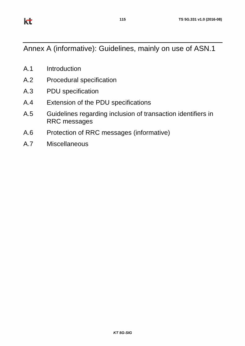
KT 5G-SIG
TS 5G.331 v1.0 (2016-08) 115
Annex A (informative): Guidelines, mainly on use of ASN.1
A.1 Introduction
A.2 Procedural specification
A.3 PDU specification
A.4 Extension of the PDU specifications
A.5 Guidelines regarding inclusion of transaction identifiers in RRC messages
A.6 Protection of RRC messages (informative)
A.7 Miscellaneous