technical report - igem · technical report page 1 of 41. ... autocad 3d, solid modelling ......
TRANSCRIPT

Institution of Gas Engineers & Managers
Technical Report Page 1 of 41
Technical Report
Barholing Investigation
Technical Report by
XXXXXXX
Sector Operations Manager
National Grid - Gas Distribution
Grade Application – Incorporated Member (IEng)
IGEM Approved Mentor – XXXXXX
Submission Date – 31st July 2007
Note: The basis of this report was created in 2001/2002 prior to National Grid merging with
Transco (Lattice Group). Therefore, the report considers Transco as the National gas
transporter and emergency service provider and any reference to Transco and its policy’s &
procedures was relevant at the time.

Institution of Gas Engineers & Managers
Technical Report Page 2 of 41
Technical Report Page
Contents
1. Executive Summary 5
2. Introduction 6
3. Barhole Tool Principles 7
(a) Basic Principles of the Barhole Tool 7
(b) Application of the Barhole Tool 8
4. Investigation & Research 10
(a) Legislation, Policies and Procedures 10
(b) Safeway Searcher Bar Literature 11
(c) Other Barholing Methods 12
(d) Barhole Operation (Transco) 12
(e) Observations of the Safeway Searcher Bar 14
(f) Barhole Related Injuries 14
(g) Consequences of an Injury 15
(h) Barhole Training and Competency Assessment 15
(i) Research Summary 16
5. Technical Investigation 17
(a) Safeway Searcher Bar Calculations 17
(b) Safeway Searcher Bar Calculation Summary 21
(c) FCO Calculations 22
(d) Analysis of calculations 23
Institution of Gas Engineers & Managers
Technical Report Page 3 of 41
Technical Report Page
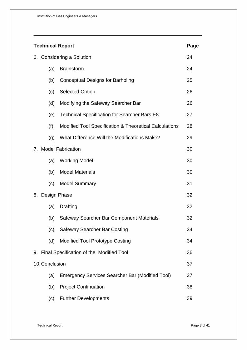
6. Considering a Solution 24
(a) Brainstorm 24
(b) Conceptual Designs for Barholing 25
(c) Selected Option 26
(d) Modifying the Safeway Searcher Bar 26
(e) Technical Specification for Searcher Bars E8 27
(f) Modified Tool Specification & Theoretical Calculations 28
(g) What Difference Will the Modifications Make? 29
7. Model Fabrication 30
(a) Working Model 30
(b) Model Materials 30
(c) Model Summary 31
8. Design Phase 32
(a) Drafting 32
(b) Safeway Searcher Bar Component Materials 32
(c) Safeway Searcher Bar Costing 34
(d) Modified Tool Prototype Costing 34
9. Final Specification of the Modified Tool 36
10. Conclusion 37
(a) Emergency Services Searcher Bar (Modified Tool) 37
(b) Project Continuation 38
(c) Further Developments 39
Institution of Gas Engineers & Managers
Technical Report Page 4 of 41
Technical Report Page
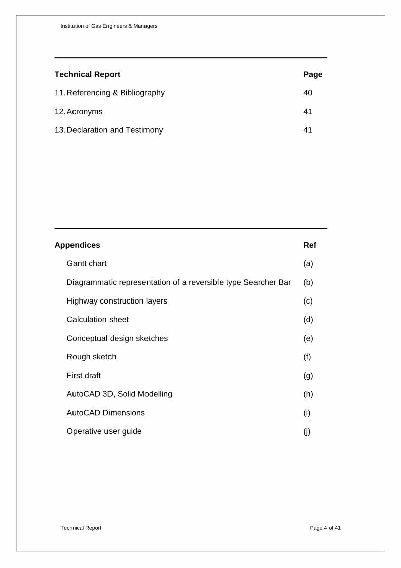
11. Referencing & Bibliography 40
12. Acronyms 41
13. Declaration and Testimony 41
Appendices Ref
Gantt chart (a)
Diagrammatic representation of a reversible type Searcher Bar (b)
Highway construction layers (c)
Calculation sheet (d)
Conceptual design sketches (e)
Rough sketch (f)
First draft (g)
AutoCAD 3D, Solid Modelling (h)
AutoCAD Dimensions (i)
Operative user guide (j)

Institution of Gas Engineers & Managers
Technical Report Page 5 of 41
‘Barholing’ is a technique utilised in the gas distribution industry, which
enables effective location and classification of gas escapes emanating from
distribution mains and services generally operating up to 200kPa.
1. Executive Summary
The barholing technique is simple in that a mechanical tool operating in a pile
driving manner is operated by a single person to penetrate a small hole in the
desired location, enabling gas samples to be taken at sub ground level.
A number of injuries had occurred to operatives using the barhole tool. This
report considers the design and operation of the barhole tool utilised within
Transco and the method employed by the operatives to carry out this
essential function. It then considers if the operation of the existing tool could
be improved and therefore reduce the likelihood of injury.
This ‘Barholing Investigation’ was the basis of my HNC mechanical
engineering project. However, this report was written specifically for
submission as an IGEM technical report and is not the actual HNC
submission. This report is still relevant to the gas industry today.
The report looks at a number of facets including; policies & procedures,
technical investigation, conceptual designs and solutions and the construction
of a working model.

Institution of Gas Engineers & Managers
Technical Report Page 6 of 41
‘Barholing’ is a technique used in the gas distribution industry to aid the
location and classification of external gas escapes, where the gas is escaping
upstream of the consumer control valve. The basic principle is to penetrate a
small diameter hole into a footway or carriageway, enabling gas samples to
be taken within the pavement structure.
2. Introduction
The barhole tool is used by First Call Operatives (FCO’s) attending public
reported gas escapes, and ‘Escape, Locate & Repair’ teams (ELR teams)
investigating outside gas escapes.
A number of Lost Time Injuries (LTI’s) and Non-Lost Time Injuries (NLTI’s)
had occurred throughout the year 2001, due to barholing activity in my local
area within the Transco East Anglia region. Any injuries within the workplace
have serious safety, health & financial implications. Therefore, following a
discussion with my line manager, we agreed that I would investigate the
suitability of the existing barhole tool and the methods of use employed by the
FCO’s as part of my HNC Mechanical Engineering project.
I wrote a project brief and action plan and I carried out a feasibility study to
determine if the project was achievable within the timescales and resources
available to me. Having concluded to proceed with the project, I devised a
Gantt chart to manage the delivery of the project (appendix a), which included
timelines and key project milestones.

Institution of Gas Engineers & Managers
Technical Report Page 7 of 41
Fig 1 Searcher bar being used by an FCO
3. Barhole Tool Principles
3 (a) Basic Principles of the Barhole Tool
The barhole tool is basically a bar, one end tapered to
penetrate the selected surface, the other end finished
with a boss head. The bar resides within a barrel,
which is electrically insulated (appendix b).
The principle of operation is that of a pile driving
action created by the barrel handle falling, which
forces the tapered end of the bar into the ground. To
achieve this, the barrel handle is raised to the top of
its stroke, and allowed to fall, thus the inside of the
barrel strikes the boss head causing the two
components to couple, transferring the energy to the
bar. As a result, the bar penetrates the surface, requiring the bar to be
withdrawn in a percussive manner, through lifting the barrel handle to the top
of its stroke causing the reverse side of the boss head to strike the base of the
barrel. The process is then repeated until the penetration depth is attained.

Institution of Gas Engineers & Managers
Technical Report Page 8 of 41
3 (b) Application of the Barhole Tool
Upon receipt of a reported gas escape, an FCO will attend the location and
ensure the safety of life and property, followed by a survey of the area with a
gas detection instrument.
When indications of gas are identified, barholing must be carried out as
detailed in Transco’s procedures. The FCO will first consult utility plans and
utilise a cable avoidance tool to mark the position of electrical cable and other
utilities plant.
The barhole tool is set to penetrate at a depth of 0.2m when barholing in the
footway. This ensures penetration into the sub layers (appendix c), whilst
considering the depths at which utility plant is expected in the footway. This
has the benefit of minimising the risk of injury through striking electric cables.
And fewer costs associated with repairs relating to underground plant
damage.
FCO’s are not permitted to barhole in the carriageway for two reasons:
Road surface can be very difficult to penetrate
Working in the road requires appropriate signing, lighting and guarding
as per the New Roads & Street Works Act (NRSWA), which is not
carried by the FCO
In circumstances where the FCO needs to barhole in the carriageway, an ELR
team would be called.

Institution of Gas Engineers & Managers
Technical Report Page 9 of 41
Following the appropriate gas samples being taken and recorded, the FCO
will either program the gas escape for monitoring and repair at a future date,
or, request the immediate assistance of an ELR team. The ELR team also use
the barhole tool but they frequently utilise a pneumatic rock drill to penetrate
hard surfaces, i.e. concrete reinforced carriageways.
An ELR team penetrate to a depth of 0.38m in the carriageway, again to
ensure penetration into the sub layers taking into consideration the depth at
which utility plant is expected. However, this report does not include a detailed
review of barholing in the carriageway.

Institution of Gas Engineers & Managers
Technical Report Page 10 of 41
4 (a) Legislation, Policies and Procedures
4. Investigation & Research
During my initial research I identified a number of documents relating to
barholing which are listed under ‘Procedures’ (Referencing & Bibliography -
section 11).
Considering that a number of operatives had been injured using the barhole
tool, I focussed on the salient points relating to the safe use of the tool.
o SBGI (Nov 1991) A Code of Practice for Barholing
Section 4.1 – ‘In no circumstances must undue force be used to drive
the searcher bar…’
Section 4.2.2 – ‘The use of rock drills of approved type is
recommended to penetrate the surface of roadways and footpaths
where the surface is exceptionally hard.’
o Transco (2001) Health Safety & Environment Book (Issue 5)
Section Barhole tool (use of) – ‘Assessment of the surface should be
taken prior to the use of the tool to reduce the risk of injury from
attempts to penetrate surfaces that are exceptionally hard’.
o Transco (1995) Field Procedures D2
Section 11 – ‘Do not use excessive force to drive in the searcher bar
and cease barholing if you feel any obstruction’.
o Transco (May 1998) Emergency Procedures EM71

Institution of Gas Engineers & Managers
Technical Report Page 11 of 41
P49 – ‘In no circumstances must undue force be used to drive the
searcher bar….’
o Transco (June 2001) Emergency Field Procedures EM72
Barholing (EM72/FS2/0601) - ‘Do not use excessive force to drive in the
searcher bar and cease barholing if you feel any obstruction’.
Note that the above documents have been superseded, but the principles
remain current today.
4 (b) Safeway Searcher Bar Literature
The barhole tool sourced by Transco was manufactured by ‘Peter Wood & Co
Ltd’. Their barhole tool, the ‘Safeway Searcher Bar’, was manufactured to
meet the Transco (Feb 1993) Technical Specification for Searcher Bars E8. I
contacted Peter Wood & Co Ltd and they sent me some literature regarding
their Searcher Bar, which included a sheet titled ‘‘How to use the impact
Searcher Bar’. Below is an extract from Peter Wood & Co Ltd How to use the
impact Searcher Bar;
‘Raise the barrel handle and force down so that the ‘top closure plug’ (inside
the handle) hits the ‘boss head’ of the spike (also inside the handle). The pile
driver action will drive the spike into the ground (soil, asphalt, or concrete –
concrete being the most difficult to penetrate’.
Institution of Gas Engineers & Managers
Technical Report Page 12 of 41
These instructions are fairly basic and do not consider the effect on the user
or provide any guidance on reducing the consequential impact on the user.
They also refer to penetrating through concrete, which is extremely
demanding on the user. However, Peter Wood & Co Ltd manufactured the
tool to the required Transco specification and was not responsible for training
Transco operatives. The training and assessment process was carried out
internally within Transco (refer to 4h).
4 (c) Other Barholing Methods
I found very little information outside of Transco relating to Barholing.
However, I did discover a company in Canada, ‘Heathus’ who produce a
‘plunger bar’. The plunger bar is designed for utility companies and is very
similar in principle to the Searcher Bar. However, it is designed to penetrate
soil only and therefore cannot be directly compared.
4 (d) Barhole Operation (Transco)
I visited 3 FCO’s at different locations to observe how they used the existing
barhole tool. My observations and discussion with the 3 FCO’s identified:
• The handle is not always raised to the maximum height
• There was a tendency to force the barhole tool in an attempt to
increase penetration
Institution of Gas Engineers & Managers
Technical Report Page 13 of 41
• The FCO’s received a degree of shock when forcing the tool as the
barrel handle strikes the boss head
• A throwing action was employed on occasion
• It was evident that there was a tendency to ‘hang on’ to the tool in an
attempt to force the bar into the ground. This could be likened to forcing
a power drill rather than letting the drill do the work.
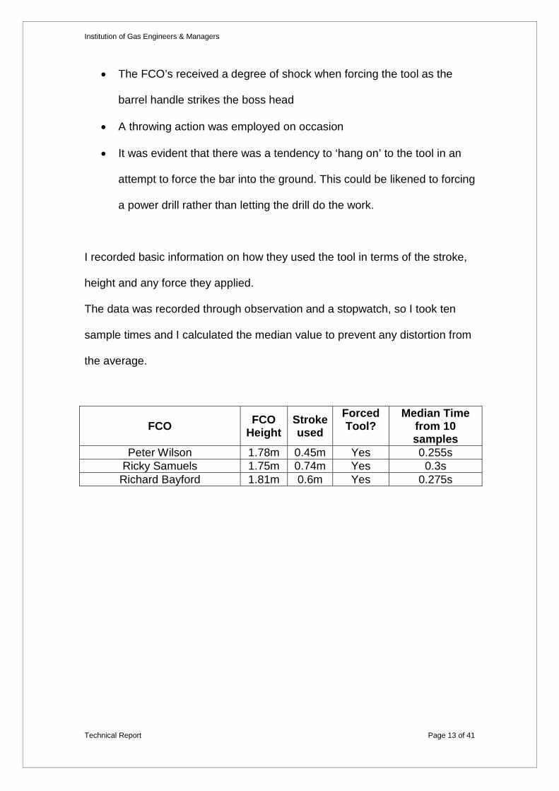
I recorded basic information on how they used the tool in terms of the stroke,
height and any force they applied.
The data was recorded through observation and a stopwatch, so I took ten
sample times and I calculated the median value to prevent any distortion from
the average.
FCO FCO Height
Stroke used
Forced Tool?
Median Time from 10 samples
Peter Wilson 1.78m 0.45m Yes 0.255s Ricky Samuels 1.75m 0.74m Yes 0.3s
Richard Bayford 1.81m 0.6m Yes 0.275s

Institution of Gas Engineers & Managers
Technical Report Page 14 of 41
4 (e) Observations of the Safeway Searcher Bar
I noticed that the reversible adaptor that enables the depth to be changed
between 0.2m and 0.38m is not suitable for use in soft ground such as a lawn
or grass verge. This is because the adaptor diameter is only 0.009 m larger
than the bar. Thus, the adaptor enters the ground resulting in a depth greater
than 0.2m achieved. This is potentially dangerous as utilities plant can be
expected below this depth.
Fig 2 Reversible Adaptor below ground level resulting in a greater penetration depth
4 (f) Barhole Related Injuries
Richard Davies (Health, Safety & Environment Manager) arranged for me to
have copies of injury reports from the incident database within the Transco
East Anglia region. There were four injuries recorded, spanning a six-month
period in 2001. Three of the four injuries related to upper body injuries through
trying to penetrate tough ground.
Reversible Adaptor Ground level Bar

Institution of Gas Engineers & Managers
Technical Report Page 15 of 41
Extracts from the incident reports included:
• Jarred elbow and shoulder barholing in tarmac footpath and concrete
slabs.
• Whilst using barhole tool, I had difficulty penetrating footpath, on doing
this I aggravated my tennis elbow injuries.
• Jarred left shoulder and neck whilst barholing.
4 (g) Consequences of an Injury
The HSE have calculated that the average economic cost to an employer for a
serious or major injury in the construction industry is approximately £17000 -
£19000 (based on year 2000 prices). In addition, the average number of days
lost per injury in the skilled craft sector is 13.4 days.
(2000/2001) “Injury Costs” (http://www.hse.gov.uk/).
4 (h) Barhole Training and Competency Assessment
An approved training service provider carries out Barhole training on a three
yearly basis. Transco employed D32/33 assessor’s carry out a competency
assessment on an annual basis on every FCO. Having been trained in the use
of the barhole tool, I can confirm that I was trained to simply raise the barrel
handle and allow it to fall freely. I was advised not to force the tool. From my
observations of the FCO’s, there is evidence that the recommended method is
not always employed.

Institution of Gas Engineers & Managers
Technical Report Page 16 of 41
4 (i) Research Summary
Use of the barhole tool is covered by a comprehensive range of Legislation,
Policies and Procedures. All of which clearly state that the operative should
not apply undue or excessive force. However, the literature from Peter Wood
& Co Ltd refers to forcing the handle down and penetrating harder surfaces
such as concrete.
Having observed FCO’s using the barhole tool, it is clear the tool is not always
used as designed despite the training and annual competence assessment.
This is reinforced by the four injuries that occurred in a six month period.
Considering this equates to an average of 13.4 days per injury per person
based on HSE Injury data, the impact on both the operative and Transco is
extremely significant.
Appropriate use of the tool through training and assessment also needs to be
considered as the injuries may have been caused through behavioural issues.
The above considerations should seek to reduce the number of injuries and
the likelihood of an FCO being injured using the barhole tool.
Consideration needs to be given to the mechanical operation of the tool and
the potential for over penetration to occur due to the reversible adaptor.

Institution of Gas Engineers & Managers
Technical Report Page 17 of 41
5 (a) Safeway Searcher Bar Calculations
5. Technical Investigation
In order to understand the force generated in the bar I carried out a number of
theoretical calculations.
Peter Wood & Co Searcher Bar dimensions
Component Dimension Reversible Plug diameter 0.025m length 0.23m weight 0.65kg (including thread guard & grub
screw) Bar diameter 0.016m length 1.315 m (including boss head) weight 2.15kg Insulated Handle length 0.95m weight 6kg
Below, is a schematic diagram of the Searcher Bar in the open and closed
position. Due to the design of the reversible plug, the raised height of 2.21m
can only be achieved with the tool in the 0.2m setting. Where the 0.38m depth
is selected, the raised height is reduced to 2.04m.
2.21m 1.37m
Closed
Open Fig 3 Schematic diagram of a Searcher Bar
Institution of Gas Engineers & Managers
Technical Report Page 18 of 41
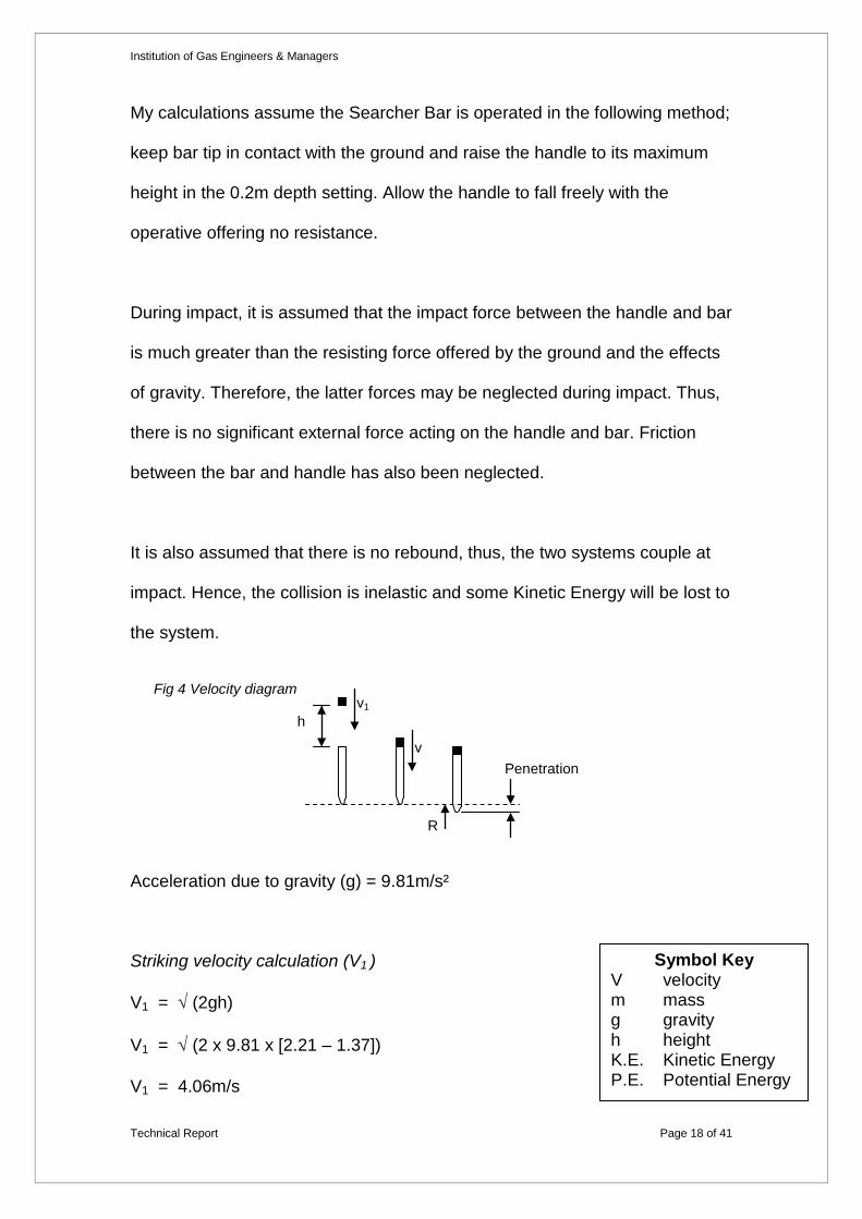
My calculations assume the Searcher Bar is operated in the following method;
keep bar tip in contact with the ground and raise the handle to its maximum
height in the 0.2m depth setting. Allow the handle to fall freely with the
operative offering no resistance.
During impact, it is assumed that the impact force between the handle and bar
is much greater than the resisting force offered by the ground and the effects
of gravity. Therefore, the latter forces may be neglected during impact. Thus,
there is no significant external force acting on the handle and bar. Friction
between the bar and handle has also been neglected.
It is also assumed that there is no rebound, thus, the two systems couple at
impact. Hence, the collision is inelastic and some Kinetic Energy will be lost to
the system.
Acceleration due to gravity (g) = 9.81m/s²
Striking velocity calculation (V1 )
V1 = √ (2gh)
V1 = √ (2 x 9.81 x [2.21 – 1.37])
V1 = 4.06m/s
v1
Penetration
Fig 4 Velocity diagram
h
v
R
Symbol Key V velocity m mass g gravity h height K.E. Kinetic Energy P.E. Potential Energy

Institution of Gas Engineers & Managers
Technical Report Page 19 of 41
Common velocity of coupled system after impact
mT V = m1 V1
8.8 V = 6.65 x 4.06
V = 3.07m/s
Kinetic energy of system after impact
Kinetic Energy = ½ mT V2
K.E. = ½ 8.8 x 3.072
K.E.= 41.47 Joules
I have assumed a constant penetration of 0.01m per stroke to provide
comparative calculations regardless of the material being penetrated.
Loss of potential energy in descending 0.01m
Lost P.E. = mT g distance
= 8.8 x 9.81 x 0.01
= 0.86328 J
Therefore, the work done by the handle and bar = K.E. + loss of P.E.
= 41.47 + 0.86328
= 42.33 J
So the resisting force, R = Work done / distance
= 42.33 / 0.01
= 4.233kN
Masses of the components m1 = 6.65kg (handle & reversible plug)
m2 = 2.15kg (bar)
m T = 8.8kg (total weight)

Institution of Gas Engineers & Managers
Technical Report Page 20 of 41
Newton’s third law of motion states that; ‘To every action there is an equal and
opposite reaction’. Therefore, the resisting force equals the force in the bar.
Thus, the force in the bar = 4.233kN
To check the accuracy of my calculations I used linear motion.
Initial velocity (u) u = 0
Final velocity (v) V = 3.07m/s (after impact)
Distance travelled (s) s = 0.01m
Acceleration (a) a = ?
V2 = u2 + 2 a s
3.072 = 2 x a x 0.01
a = 471.245m/s2
F = m a
F = 8.8 x 471.245
F = 4.147kN
Note: this force does not take potential energy into consideration.
K.E / distance = 41.47 / 0.01 = 4.147kN
Thus, the force is 4.147 kN and with the lost Potential Energy included, the
force is 4.233kN.
Institution of Gas Engineers & Managers
Technical Report Page 21 of 41
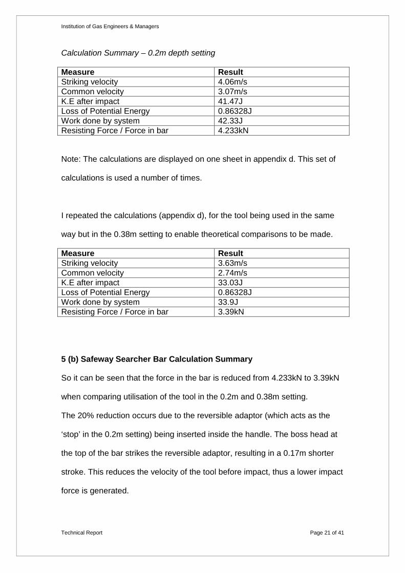
Calculation Summary – 0.2m depth setting
Measure Result Striking velocity 4.06m/s Common velocity 3.07m/s K.E after impact 41.47J Loss of Potential Energy 0.86328J Work done by system 42.33J Resisting Force / Force in bar 4.233kN
Note: The calculations are displayed on one sheet in appendix d. This set of
calculations is used a number of times.
I repeated the calculations (appendix d), for the tool being used in the same
way but in the 0.38m setting to enable theoretical comparisons to be made.
Measure Result Striking velocity 3.63m/s Common velocity 2.74m/s K.E after impact 33.03J Loss of Potential Energy 0.86328J Work done by system 33.9J Resisting Force / Force in bar 3.39kN
5 (b) Safeway Searcher Bar Calculation Summary
So it can be seen that the force in the bar is reduced from 4.233kN to 3.39kN
when comparing utilisation of the tool in the 0.2m and 0.38m setting.
The 20% reduction occurs due to the reversible adaptor (which acts as the
‘stop’ in the 0.2m setting) being inserted inside the handle. The boss head at
the top of the bar strikes the reversible adaptor, resulting in a 0.17m shorter
stroke. This reduces the velocity of the tool before impact, thus a lower impact
force is generated.

Institution of Gas Engineers & Managers
Technical Report Page 22 of 41
5 (c) FCO Calculations
Considering my theoretical calculations, I applied the same process to my
observations of the three FCO’s; refer to 4(d) for values used.
FCO - Peter Wilson
As Peter forced the tool, we can no longer use gravity for the acceleration.
Therefore, I applied linear motion and the median time and stroke Peter used.
s = u t + ½ a t2
0.45 = ½ a x 0.2552
a = 13.84m/s2
Calculation Summary
Measure Result Striking velocity 3.53m/s Common velocity 2.67m/s K.E after impact 31.37J Loss of Potential Energy 1.21792J Work done by system 35.59J Resisting Force / Force in bar 3.559kN
So, it can be seen that although Peter exerted his own force on the barhole
tool, the reduction in stroke resulted in a lower striking velocity and
subsequently a lower force in the bar. In fact Peter is exerting more energy
and is therefore at risk of injuring himself.

Institution of Gas Engineers & Managers
Technical Report Page 23 of 41
I repeated this exercise with the 2 other FCO’s.
FCO Acceleration Force in bar Peter Wilson 13.84m/s2 3.559kN
Ricky Samuels 16.44m/s2 6.267kN Richard Bayford 15.87m/s2 4.931kN
It can be seen that the method of operation can make a vast difference with a
75% variation in force calculated between Peter and Ricky.
5 (d) Analysis of calculations
FCO Stroke (m)
Striking Velocity (m/s)
Common Velocity (m/s) Force (kN)
Peter Wilson 0.45 3.53 2.67 3.559 Ricky Samuels 0.74 4.93 3.73 6.267
Richard Bayford 0.6 4.36 3.3 4.931
Freefall
0.2m setting 0.84 4.06 3.07 4.233 0.38m setting 0.67 3.63 2.74 3.39
My calculations suggest that exerting force on the tool does not necessarily
mean more force in the bar at impact. It can be seen that Peter Wilson
produced considerably less force, which is due to the shorter stroke he
adopted. Simply raising the handle to the top of its stroke, and allowing the
handle to freefall would have produced more force.
Ricky Samuels was able to exceed the force obtainable via freefall alone. By
adopting a longer stroke than Peter and forcing the tool an increase of almost
50% can be seen.
It is clear from my observations that the longer the stroke, and the greater the
velocity, the resultant force is greater.

Institution of Gas Engineers & Managers
Technical Report Page 24 of 41
6 (a) Brainstorm
6. Considering a Solution
Reflecting on the outcome of my research and calculations, I brainstormed a
list of points that should be considered:
• Used by a single operative
• Health and safety implications on using the tool (reduce injuries)
• Operative competency training
• Portable tool and ability to safely store on vehicle
• Weight of tool
• Materials used in construction to ensure tool is robust
• Capable of penetrating tar-macadam and dense bitumen macadam
• Used in gaseous atmospheres
• Insulated to prevent electric shock (cable strike)
• Limit depth penetration (prevent over penetration)
• Conforms to Legislation, Policies, Procedures and Standards
• Use of the tool in the 0.38m setting results in less force in the bar, yet
the material to be penetrated is more substantial
• Operatives are able to comply with relevant Legislation, Policies and
Procedures
• Generate a greater force within the bar, without the operative ‘forcing’
the tool

Institution of Gas Engineers & Managers
Technical Report Page 25 of 41
6 (b) Conceptual Designs for Barholing
I then drafted a number of concepts (appendix e) and I have detailed the
advantages & disadvantages of each in the table below.
Design Number Design Type Advantages Disadvantages
1 Tripod
• User not in contact with tool at point of impact
• Stroke is very short - Low velocity at impact
• Ratchet mechanism needed to raise weight
• Bulky • Awkward to handle and
store
2 Hydraulic Barhole Tool
• Hydraulic fluid cushions the impact for the user
• Potential for oil to leak • Higher maintenance costs • More complex to
manufacture
3 Spring Loaded Handles
• Impact is cushioned for user by spring loaded handles
• Not suitable for short or tall people
• Tool could rebound • Awkward to store on
vehicle • Relies on the user firmly
holding the tool to work
4 Incorporated Spring
• Impact is cushioned by spring loaded
• Tool could rebound on impact
• Relies on the user firmly holding the tool to work
5 Modified Existing Tool
• Increased length creating a longer stroke
• Increased weight to increase the velocity before impact
• No reversible adaptor
• Only able to penetrate to 200mm depth
• Existing racking in vehicle needs to be longer
• Slightly more cumbersome due to weight and length

Institution of Gas Engineers & Managers
Technical Report Page 26 of 41
6 (c) Selected Option
During my feasibility study I identified a number of constraints, the main
issues being the timeline of the project, the time available for me to work on
the project and no financial budget. Given the limited scope of resources, it
would not be feasible to develop a new concept. Therefore, considering my
investigation and research I selected design number 5.
6 (d) Modifying the Safeway Searcher Bar
I decided to modify the tool as detailed in the table below, within the scope of
the E8 document.
Modification Advantage Increased length (longer stroke of 1m)
E8 / Design 4.5 - Transco will consider variations above 0.66m
Increased velocity of bar
Increased weight (10kg) E8 / Design 4.15 - 10kg is the maximum permissible weight
Greater mass will create more force
No reversible adaptor
E8 / Design 4.3 - Permissible to limit depth to one setting
Minimise the risk of damaging underground plant
New adaptor or guide has bigger diameter to prevent over penetration E8 / Design 4.3 – Requirement to limit depth of penetration
Minimise the risk of damaging underground plant
0.2m depth penetration only
E8 / Design 4.3 - Permissible to limit depth to one setting
Minimise the risk of damaging underground plant

Institution of Gas Engineers & Managers
Technical Report Page 27 of 41
The disadvantage of my modifications is that the Searcher Bar would only
penetrate to 0.2m depth. However, the modified tool is being designed for
FCO’s who do not require the use of 0.38m penetration. Considering there are
approximately 2500 FCO’s in Transco, it is entirely feasible to produce a
Searcher Bar specifically for their use. This will also eliminate the significant
safety issue of over penetration.
6 (e) Technical Specification for Searcher Bars E8
E8 provides detail on the required specification for Searcher Bars used for
barholing operations, including dimensions, materials and performance. I have
listed below a number of the key points within E8 that will affect any design
modifications to the Searcher Bar.
• Shall incorporate means to limit penetration to 200mm and/or 380mm
• Minimum stroke of 560mm. Maximum stroke shall normally be 660mm
but Transco may consider variations
• Electrical insulation shall not be less than 600mm. No slip allowed
between insulation and handle
• Outside diameter shall not exceed 65mm
• The weight of the handle shall not be less than 4.5kg and the overall
weight of the equipment shall not be greater than 10kg

Institution of Gas Engineers & Managers
Technical Report Page 28 of 41
6 (f) Modified Tool Specification & Theoretical Calculations
I drafted a rough sketch (appendix f) and considered the components
required.
Bar - Existing Safeway Searcher Bar can be utilised, thus saving costs.
Handle - New length to give a maximum stroke of 1m.
• Length 1.115m
• Diameters
o Barrel int 0.033m , ext 0.041m , Insulation 0.0065m
• Weight approx 7.04kg (based on Safeway Searcher Bar assuming
same materials used and weight is uniform 6kg / 0.95 = 6.3158kg/m x
1.115m = 7.04kg)
Guide - The guide is smaller than the existing reversible adaptor, although
greater in diameter to prevent over penetration.
• Diameters
o Ext 0.05m , thread 0.033m , bar securing screw 0.008m
• Weight approx 0.75kg

Institution of Gas Engineers & Managers
Technical Report Page 29 of 41
Based on previous theoretical calculations as shown in appendix d, I
calculated the force in the bar considering the modified components.
Measure Result Striking velocity 4.43m/s Common velocity 3.472m/s K.E after impact 59.91J Loss of Potential Energy 0.975J Work done by system 60.89J Resisting Force / Force in bar 6.089kN
6 (g) What Difference Will the Modifications Make?
The theoretical calculations show that the force achieved is higher than that of
Ricky Samuels, who exerted his own force on the tool. The proposed modified
tool is able to achieve that level of force through gravity alone, producing 44%
more force than the Safeway Searcher Bar.
Operation Stroke (m)
Striking Velocity
(m/s)
Common Velocity
(m/s)
Kinetic Energy (Joules)
Force (kN)
FCO (Ricky Samuels) 0.74 4.93 3.73 61.22 6.267
Safeway Searcher Bar – 0.2m depth
(Freefall) 0.84 4.06 3.07 41.47 4.233
Modified Tool (Freefall) 1 4.43 3.544 62.8 6.378

Institution of Gas Engineers & Managers
Technical Report Page 30 of 41
7 (a) Working Model
7. Model Fabrication
After creating a first draft of the tool on graph paper (appendix g), I drafted the
model tool in AutoCAD 2000 using solid modelling techniques. This gave
three-dimensional views and assisted with the production of the working
model.
The model was constructed from materials that were readily available in the
machine shop, such as steel and brass.
Dimensions are approximately 1/3 size in length, and diameters are
approximately ½ size. Components produced included: bar (inc boss head),
barrel, end plug, guide, and bar securing screw.
7 (b) Model Materials
Barrel: The barrel is made from steel and is drilled out to accept the bar. Its
external diameter is 0.020m and it is internally threaded at both ends.
End plug: The end plug is externally threaded and acts as the top striking
face. It is constructed from the same material as the barrel, although it is not
drilled out.
Bar (inc boss head): The bar was constructed from solid steel and has a tip of
45°. The top end of the bar is threaded to accept the boss head. The bar is
0.008m and the boss head is 0.010m, which is drilled and tapped to connect
to the bar.

Institution of Gas Engineers & Managers
Technical Report Page 31 of 41
The striking face of the boss head has a radiused edge to prevent the head
from being ‘mushroomed’, ensuring the boss head does not interfere with the
inside of the barrel.
Guide: The guide is made from steel and has an external thread. When
screwed into the bottom of the barrel it is flush with the whole barrel. The
oversized section diameter is 0.030m and demonstrates the ‘fixed stop’ to
prevent over penetration. It is also drilled to allow the bar securing screw to
pass through the cross sectional area to the bar. The guide was then
quenched in oil to give a finished look (oil blackening).
Bar securing screw: The bar securing screw is made from brass because it is
a softer metal and therefore will not damage the bar. The screw head is
considerably oversized, as it is a functional part of the model and prevents the
bar from sliding which is a safety feature, even when considering a model.
The head of the screw has been knurled to provide a greater grip when
tightening the screw.
7 (c) Model Summary
The model serves as a good depiction of the modified tool and it fully
demonstrates the principle of operation. I was not able to electrically insulate
the barrel handle as I did not have sufficient resources. However, this does
not detract from the principle of operation.

Institution of Gas Engineers & Managers
Technical Report Page 32 of 41
8 (a) Drafting
8. Design Phase of the Modified Tool
I drafted the modified tool in AutoCAD 2000 using solid modelling techniques
in a 3D environment (appendix h). I also drafted the components of the tool to
define the specific measurements (appendix i).
The final drawings included a number of small changes that were identified
whilst producing the model;
• When the guide is inserted into the barrel in now finishes flush
• The top closure plug is threaded and is not secured using an
interference fit
• The hole through the guide for the bar is 0.0163m. This is because a
small gap is required to prevent a vacuum forming in the barrel, thus
preventing the bar from moving
8 (b) Safeway Searcher Bar Component Materials
The materials used by Peter Wood & Co Ltd to produce the Safeway
Searcher Bar were adequate and meet the specification of E8. The materials
have been seen to demonstrate the withstanding of ‘in-service’ treatment,
assuming the tool is used appropriately.
Bar: The bar is constructed from nickel-chrome-molybdenum steel, which is
often used for gears in automobiles and machines, where resistance to shock
and fatigue is important.

Institution of Gas Engineers & Managers
Technical Report Page 33 of 41
The bar tip is hardened to 55-60 HRC, which provides immense wear and
impact resistance. The top face of the boss head (striking face) is heat treated
to 35-40 HRC, again to provide impact resistance.
Steel grade – 817M40 (T) (EN24T) Standard - BS 970
Barrel: The barrel is made from steel and is a cold drawn seamless tube.
Standard - BS 2T 68:1980 (Specification for cold drawn 18/10 chromium-
nickel corrosion-resisting steel tube (niobium stabilized: 800 MPa) (weldable)
Guide & Top Closure Plug: Constructed from nickel-chromium-molybdenum
steel and the striking face’s are heat treated to 35-40 HRC.
Steel – 070M55 (T) (EN9) Standard – BS 970
Bar securing screw: I have decided to use brass for my bar securing screw, as
it is a very soft metal. If a hard metal is used it could damage the bar and
therefore, affect the operation of the tool.
Standard - BS 768:1958 (Specification for slotted grub screws)
Insulation: The insulation is made from natural rubber as it has high tensile
strength, good resistance to abrasion, tear and fatigue, excellent electrical
properties and low temperature performance.
The rubber is extruded onto the barrel and has a 6.5mm covering. The
insulation must be able to withstand current leakage testing (as per E8).
Standard - BS 3054:1959 (Specification for fireman's axe with rubber
insulated handle)

Institution of Gas Engineers & Managers
Technical Report Page 34 of 41
8 (c) Safeway Searcher Bar Costing
The existing complete Safeway Searcher Bar costs £73.00 excluding VAT.
Individual components are priced as follows (all exclude VAT):
• Bar £15.83
• Reversible adaptor £10.40
• Insulated handle £53.50
• Thread guard £2.89
• Thumb screws £0.28
8 (d) Modified Tool Prototype Costing
In order to produce a full size prototype I would need to purchase the following
minimum materials (all prices exclude VAT and carriage), as detailed in the
table below:
Component Material Size Sourced from Cost
Bar Nickel-chrome-molybdenum
steel
0.04m Dia 2m length
Abrapulman www.pulmans.co.uk £22.00
Guide & Top closure
plug
Nickel-chrome-molybdenum
steel
0.050m Dia 1m length
Abrapulman www.pulmans.co.uk £18.00
Bar securing
screw
Brass Rod 0.021m Dia 0.5m length
RS Components (www.rswww.com) £16.85
Barrel
Cold drawn seamless steel
tube
Dia 0.040 - 0.045m 2m
length
21st Century Steels
Approx £25-30
Rubber insulation
Rubber N/A
Essential Equipment Limited (www.essentialequi
pment.co.uk)
POA

Institution of Gas Engineers & Managers
Technical Report Page 35 of 41
In addition to the material costs I would need to consider the following costs:
• Machine shop
• Further heat treatment of the metals
• Rubber extrusion and bonding
• Wasted material due to minimum order quantity
Obviously building a prototype would be very expensive and would cost 4 to 5
times the £73.00 quoted by Peter Wood & Co Ltd for their complete tool. Peter
Wood & Co Ltd is clearly able to offer such low costs by mass-producing their
Searcher Bar (Transco have bought over 4000 Searcher Bars and they also
sell their tool to water utility industry, landfill companies and local authorities).
As previously identified, I did not have the resources to build and test a full
prototype.

Institution of Gas Engineers & Managers
Technical Report Page 36 of 41
9. Final Specification of the Modified Tool
My modified tool, the ‘Emergency Services Searcher Bar’ is designed
specifically for the 2500 First Call Operatives employed by Transco. The
Searcher Bar has a fixed depth of 0.2m and is suitable for penetrating a range
of surfaces including:
o Soil
o Tarmacadam
o Dense bitumen tarmacadam
o Clay
o Rubble/Hardcore
Note: The Searcher Bar is not designed for penetrating concrete.
Technical Specification
Part Specification Weight kg Bar Manufactured from nickel-chrome-
molybdenum steel Bar tip is hardened to 55-60 HRC Boss head striking face, hardened to 35-40 HRC
2.15kg
Barrel Cold drawn seamless steel tube
Combined 7.79kg
Guide & Top Closure Plug
Manufactured from nickel-chrome-molybdenum steel Striking face, hardened to 35-40 HRC
Bar Securing Screw
Manufactured from brass
Insulation Rubber insulation 6.5mm thick
Total Weight (theoretical) - refer to 6 (f)
9.94kg

Institution of Gas Engineers & Managers
Technical Report Page 37 of 41
10 (a) Emergency Services Searcher Bar (Modified Tool)
10. Conclusion
The ‘Emergency Services Searcher Bar’ produces over 44% more force than
the Peter Wood & Co Ltd Safeway Searcher Bar. The increase in force has
been achieved by increasing the striking velocity and therefore the combined
velocity of the handle and bar as it penetrates the surface. This has been
attained through increasing the weight from 8.8kg to 9.94kg and the length of
the stroke from 0.8m to 1m, an increase of 13% and 25% respectively.
The substantial increase in force will enable operatives to successfully barhole
without the need to exert their own force on the barrel handle. Therefore, the
potential of injuries resulting is greatly reduced.
Withdrawal of the Searcher Bar can be carried out in the same way, with no
additional effort required from the operative. This is due to the removal of the
reversible adaptor. Thus, the withdrawal stroke is not affected by the
increased stroke. Removal of the reversible adaptor also eliminates the
potential for over penetration which is a significant safety issue.
In addition, to address the behavioural factors, I produced an operative user
guide to reinforce and promote safe practices when using the tool (appendix
j). This is particularly important as the benefits gained through modifying the
tool would be lost if the tool is not correctly used.

Institution of Gas Engineers & Managers
Technical Report Page 38 of 41
10 (b) Project Continuation
During the project I recorded a number of factors that would require
consideration if the project was continued;
• The effects of friction between the barrel and bar. Could a different
material reduce any friction? Or is it insignificant?
• Incorporating a self-lubricating bush into the guide, thus no oiling of the
bar required.
• Carry out extensive field trials using sophisticated equipment to
accurately measure levels of force in the bar.
• Carry out extensive field trials to determine any shock received by the
operative.
• Consider the effects of altering the angle of the tip of the bar.
• Consider the effects on the force if the handle and bar don’t couple at
impact, i.e. rebound rates and variations on different surfaces
• Investigate my conceptual ideas (appendix e)
• Investigate the tool being used in the 0.38m setting in the carriageway
• Consider the Hand Arm Vibration Syndrome (HAVS) regulations
introduced during 2005

Institution of Gas Engineers & Managers
Technical Report Page 39 of 41
10 (c) Further Developments
If I was given the opportunity to develop my modified tool proposal further,
taking into account the budgetary constraints, I would have looked to form a
partnership between Transco & Peter Wood & Co. Considering their
knowledge in this field and the resources available to them, it would present a
minimal risk strategy for both parties. Should the collaboration be successful,
Transco will benefit through reduced associated injuries, with Peter Wood &
Co benefiting through enhancing their product, which they can then sell to
Transco and other organisations.

Institution of Gas Engineers & Managers
Technical Report Page 40 of 41
In research and the writing of this project, I referred to the following
information sources:
11. Referencing & Bibliography
Books Timings, R.L (1990) Engineering Materials Vol 2, Harlow: Longman Hannah, J & Hillier, M.J (1995) Applied Mechanics (3rd edition), Harlow: Pearson Bolton, W (1999) Higher Engineering Science, Oxford:Newnes Lock, D (2000) Project Management (7th edition), Aldershot:Gower Procedures SBGI (Nov 1991) A Code of Practice for Barholing Transco (Feb 1993) Technical Specification for Searcher Bars E8 Transco (1995) Field Procedures D2 Transco (May 1998) Emergency Procedures EM71 Transco (2001) Health Safety & Environment Book (Issue 5) Transco (June 2001) Emergency Field Procedures EM72 HSE (2000) Avoiding Danger from Underground Services HSG47 Literature Peter Wood & Co Ltd Safeway Searcher bar Peter Wood & Co Ltd How to use the impact Searcher Bar Transco (1996) Classifier Training Material Internet http://www.heathus.com/ Gas Consultants (Houston & Canada) http://www.bsonline.techindex.co.uk/ British Standards online http://www.pulmans.co.uk Abrampulman Material stockists http://www.specialiststeels.co.uk Steel stockists http://rswww.com/ RS Components http://www.essentialequipment.co.uk/ Rubber extrusion & bonding http://www.hse.gov.uk/ Injury Statisitics Company Intranet Transco Lattice Acknowledgements I would like to formally acknowledge XXXXX & XXXXX from Harlow College
for their assistance with the production of the working model.

Institution of Gas Engineers & Managers
Technical Report Page 41 of 41
Acronym
12. Acronyms
Description FCO First Call Operative ELR Escape, Locate & Repair LTI Lost Time Injuries
NLTI Non Lost Time Injuries HSE Health & Safety Executive HNC Higher National Certificate IGEM Institution of Gas Engineers & Managers
D32/33 NVQ Skills Assessor
13. Declaration and Testimony
I certify that I have read the Technical Report written by XXXXX and confirm
that to the best of my knowledge it is true and accurate.
Name: ___________________________________________________
Signed: __________________________________________________
Professional qualifications: ___________________________________
Relationship to candidate: ____________________________________
Date: ____________________________________________________