technical instructions for safety recall … · technical instructions . for . safety recall elf ....
TRANSCRIPT
TECHNICAL INSTRUCTIONS
FOR
SAFETY RECALL ELF
FUEL PRESSURE SENSOR GASKET
CERTAIN 2006 - 2010 MY IS 250 (4GR-FSE Engine)
2010 MY IS 250C (4GR-FSE Engine)
All dealership associates involved in the campaign process are required to successfully complete E-Learning course SC13A. To ensure that all vehicles have the repair performed correctly; technicians performing this recall repair are required to currently hold at least one of the following certifications levels: • Certified, Senior, or Master Technician • Certified, Senior, or Master Diagnostic Technician
ELF GR ENGINE FUEL PRESSURE SENSOR GASKET VIDEO OVERVIEW
1

I. OPERATION FLOWCHART
Verify Vehicle Eligibility1. Check the TIS Vehicle Inquiry
System.No further action required.Not Covered
Campaign complete, return the vehicle to the customer.
Covered
Has SSC 7LC been completed?2006 IS 250
Has SSC 9LA been completed?2006-2008 IS 250
Has SSC BLA been completed?
YES
YES
Perform SSC ELF
YES
NO
Perform SSC 7LC and or SSC 9LA if applicable.
Refer to Section VI & VII to performthe steps necessary to
complete SSC ELF
NO
If a vehicle is applicable to SSC BLA it has now been superseded by SSC ELF
NOTE: • Check the TIS Vehicle Inquiry System to confirm the VIN is involved in this Safety Recall, and that the campaign
has not already been completed prior to dealer shipment or by another dealer. • TMS warranty will not reimburse dealers for repairs conducted on vehicles that are not affected or were
completed by another dealer.
II. PREPARATION
A. PARTS
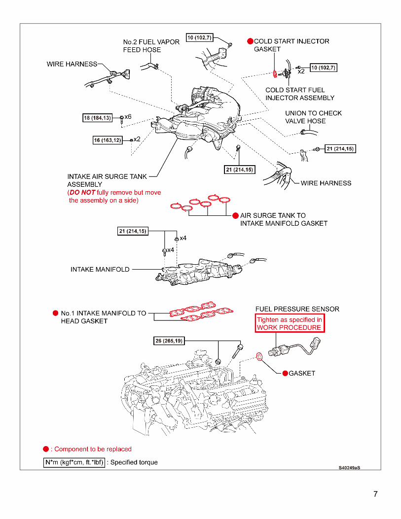
Model Part Number Part Description Quantity IS 250 & IS 250C 04004-35831 Fuel Pressure Sensor Gasket Kit 1
The kit contains the following parts 90430-12026 Fuel Pressure Sensor Gasket 1
17176-31170 Air Surge Tank to Intake Manifold Gasket 1
17177-31021 Intake Manifold to Cylinder Head Gasket 2
23293-31010 Cold Start Injector Gasket 1 09264-99020 Polishing Brush Pad 1
B. TOOLS
• Standard hand tools • Techstream • Blow gun • Torque wrench • Air Ratchet
2
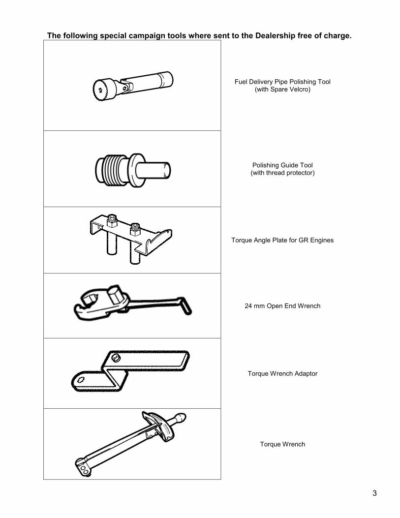
The following special campaign tools where sent to the Dealership free of charge.
Fuel Delivery Pipe Polishing Tool (with Spare Velcro)
Polishing Guide Tool (with thread protector)
Torque Angle Plate for GR Engines
24 mm Open End Wrench
Torque Wrench Adaptor
Torque Wrench
3
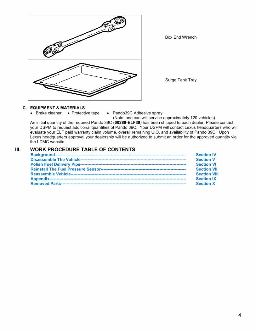
Box End Wrench
Surge Tank Tray
C. EQUIPMENT & MATERIALS
• Brake cleaner
• Protective tape
• Pando39C Adhesive spray (Note: one can will service approximately 120 vehicles)
An initial quantity of the required Pando 39C (00289-ELF39) has been shipped to each dealer. Please contact your DSPM to request additional quantities of Pando 39C. Your DSPM will contact Lexus headquarters who will evaluate your ELF paid warranty claim volume, overall remaining UIO, and availability of Pando 39C. Upon Lexus headquarters approval your dealership will be authorized to submit an order for the approved quantity via the LCMC website.
III. WORK PROCEDURE TABLE OF CONTENTS Background---------------------------------------------------------------------------------------------- Section IV Disassemble The Vehicle---------------------------------------------------------------------------- Section V Polish Fuel Delivery Pipe---------------------------------------------------------------------------- Section VI Reinstall The Fuel Pressure Sensor------------------------------------------------------------- Section VII Reassemble Vehicle----------------------------------------------------------------------------------- Section VIII Appendix-------------------------------------------------------------------------------------------------- Section IX Removed Parts------------------------------------------------------------------------------------------ Section X
4
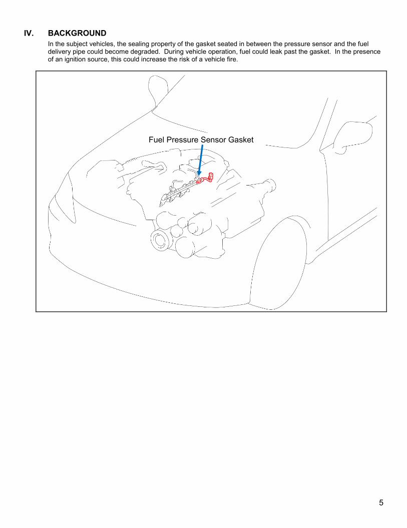
IV. BACKGROUND
In the subject vehicles, the sealing property of the gasket seated in between the pressure sensor and the fuel delivery pipe could become degraded. During vehicle operation, fuel could leak past the gasket. In the presence of an ignition source, this could increase the risk of a vehicle fire.
Fuel Pressure Sensor Gasket
5

V. DISASSEMBLE THE VEHICLE
A. COMPONENTS
6
7
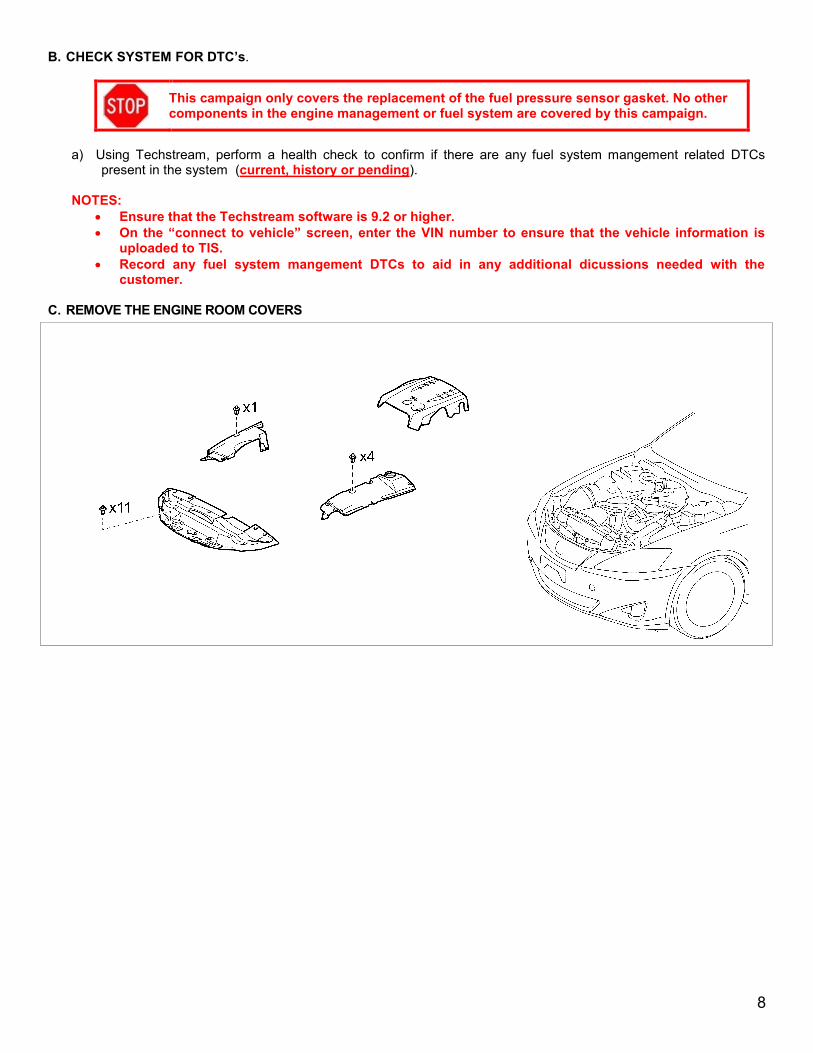
B. CHECK SYSTEM FOR DTC’s.
This campaign only covers the replacement of the fuel pressure sensor gasket. No other components in the engine management or fuel system are covered by this campaign.
a) Using Techstream, perform a health check to confirm if there are any fuel system mangement related DTCs
present in the system (current, history or pending).
NOTES: • Ensure that the Techstream software is 9.2 or higher. • On the “connect to vehicle” screen, enter the VIN number to ensure that the vehicle information is
uploaded to TIS. • Record any fuel system mangement DTCs to aid in any additional dicussions needed with the
customer.
C. REMOVE THE ENGINE ROOM COVERS
8

D. DISCHARGE THE FUEL SYSTEM PRESSURE
• DO NOT disconnect any part of the fuel system until you have discharged the fuel system pressure.
• Even after discharging the fuel system pressure; place a shop cloth around the fuel pressure sensor as you separate it to reduce the risk of fuel spraying on yourself and in the engine compartment.
1. DISCHARGE THE FUEL SYSTEM PRESSURE
a) Remove the relay block cover.
b) Remove the F/PMP fuse.
c) Start the engine.
d) After the engine has stopped, turn the ignition switch OFF.
NOTE: DTCs related to fuel pressure, lean fuel mixture, and/or engine stop may be detected.
e) Remove the fuel tank cap to discharge the fuel tank
pressure.
NOTE: DO NOT reinstall the fuel tank cap.
2. DISCONNECT THE NEGATIVE BATTERY CABLE NOTE: For models with a navigation system, wait at least 6
minutes before disconnecting the battery. The system requires approximately 6 minutes to save information and settings after vehicle shut down.
a) Reinstall the F/PMP fuse.
b) Reinstall the relay block cover.
9
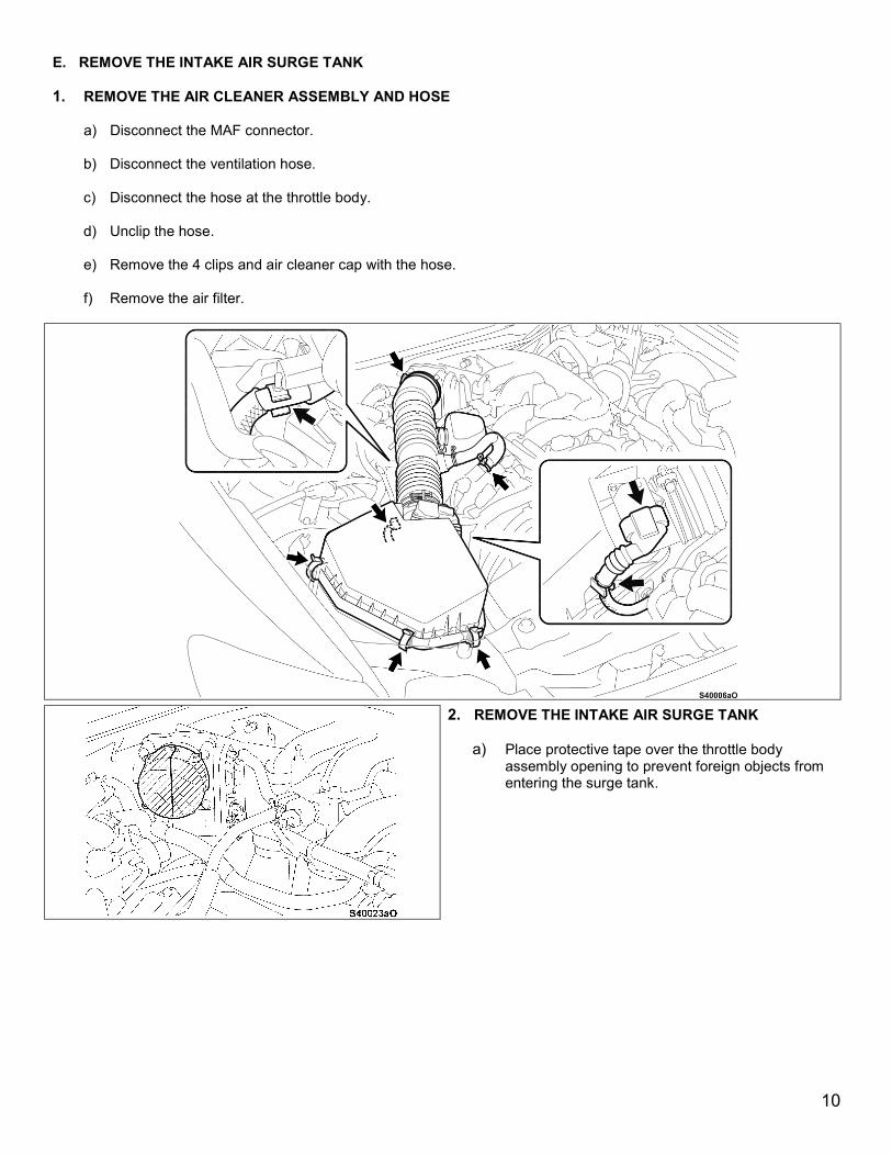
E. REMOVE THE INTAKE AIR SURGE TANK
1. REMOVE THE AIR CLEANER ASSEMBLY AND HOSE
a) Disconnect the MAF connector.
b) Disconnect the ventilation hose.
c) Disconnect the hose at the throttle body.
d) Unclip the hose.
e) Remove the 4 clips and air cleaner cap with the hose.
f) Remove the air filter.
2. REMOVE THE INTAKE AIR SURGE TANK
a) Place protective tape over the throttle body assembly opening to prevent foreign objects from entering the surge tank.
10

b) Disconnect the throttle body connector.
c) Disconnect the No. 2 fuel vapor hose.
d) Disconnect the vacuum switching valve connector.
e) Disengage the 2 wire harness clamps and disconnect the No.2 water by-pass hose from the air surge tank.
f) Using the supplied box wrench remove the bolt for the water pipe stay.
11
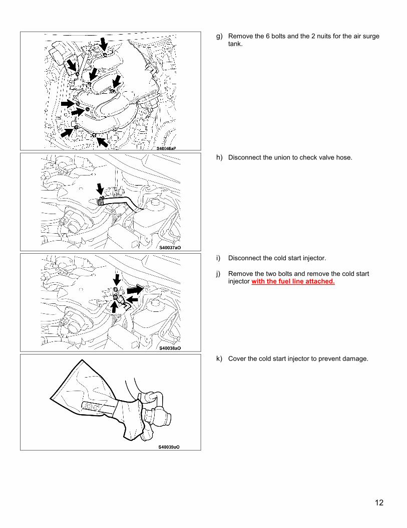
g) Remove the 6 bolts and the 2 nuits for the air surge tank.
h) Disconnect the union to check valve hose.
i) Disconnect the cold start injector.
j) Remove the two bolts and remove the cold start injector with the fuel line attached.
k) Cover the cold start injector to prevent damage.
12
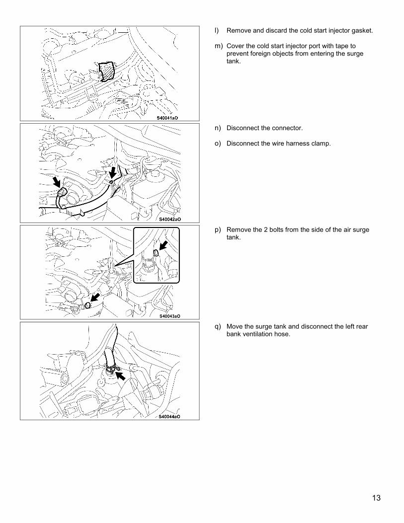
l) Remove and discard the cold start injector gasket.
m) Cover the cold start injector port with tape to prevent foreign objects from entering the surge tank.
n) Disconnect the connector.
o) Disconnect the wire harness clamp.
p) Remove the 2 bolts from the side of the air surge tank.
q) Move the surge tank and disconnect the left rear bank ventilation hose.
13

r) Detach the clamp of the SCV position sensor connector from the surge tank.
s) Cover the supplied sure tank tray with a cloth and place the tray on the right side of the engine compartment.
t) Ensure the air surge tank is unbolted and carefully separate it from the intake manifold and place it on the tray as shown.
NOTE: Ensure that other parts in the engine compartment are not damaged by the air surge tank.
Do not hold or store the air surge tank vertically, engine oil could leak out. In the event that oil leaks from the t-body clean it with a cloth. DO NOT use brake clean as it could damage the t-body.
Ensure that the water hose is not tensioned.
14

u) Remove and discard the air surge tank gasket.
v) Place protective tape over the intake manifold ports to prevent foreign objects from entering.
3. REMOVE THE INTAKE MANIFOLD a) Disconnect the 2 connectors.
b) Remove the 4 bolts and 4 nuts and remove the
intake manifold.
c) Remove and discard the intake manifold gaskets.
15
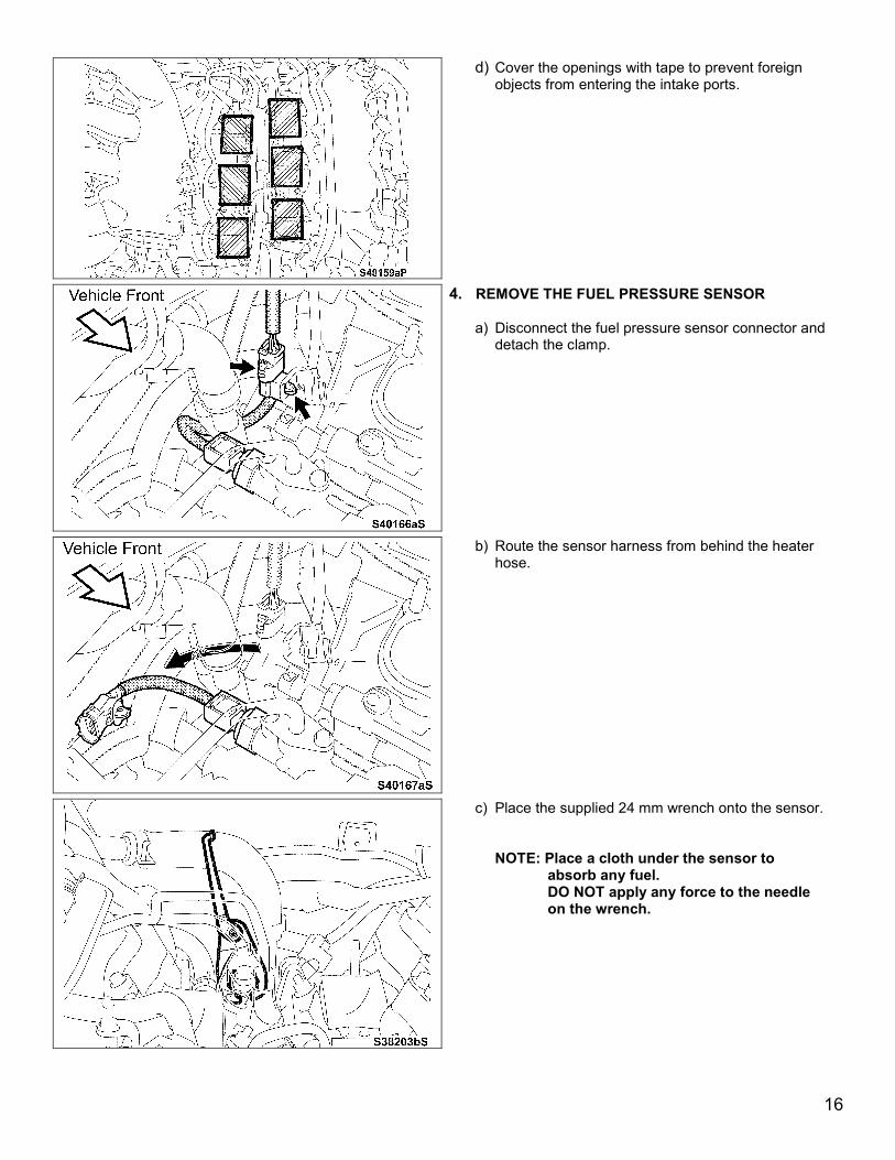
d) Cover the openings with tape to prevent foreign objects from entering the intake ports.
4. REMOVE THE FUEL PRESSURE SENSOR a) Disconnect the fuel pressure sensor connector and
detach the clamp.
b) Route the sensor harness from behind the heater hose.
c) Place the supplied 24 mm wrench onto the sensor.
NOTE: Place a cloth under the sensor to absorb any fuel. DO NOT apply any force to the needle on the wrench.
16
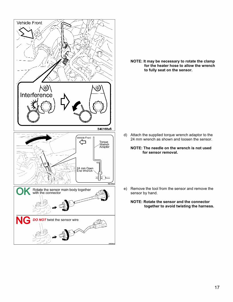
NOTE: It may be necessary to rotate the clamp
for the heater hose to allow the wrench to fully seat on the sensor.
d) Attach the supplied torque wrench adaptor to the 24 mm wrench as shown and loosen the sensor. NOTE: The needle on the wrench is not used
for sensor removal.
e) Remove the tool from the sensor and remove the sensor by hand. NOTE: Rotate the sensor and the connector
together to avoid twisting the harness.
17

f) Remove and discard the sensor gasket.
The old pressure sensor will be reused. DO NOT drop the sensor If it is dropped it must be replaced
VI. POLISH THE FUEL DELIVERY PIPE
1. DISCONNECT CONNECTOR a) Disconnect the connector for the water by-pass glow
plug (if equipped).
2. INSTALL GUIDE a) Remove the supplied guide from the thread
protector.
b) Inspect and clean the threads of the guide.
NOTE: DO NOT dispose of the guide protector it is needed to store the guide. Replace the guide if the threads are damaged.
18

c) Install the guide into the end of the fuel delivery pipe finger tight.
d) Inspect the polishing pad that is contained in the parts kit. Ensure that the center piece of the new pad is removed.
NOTE: DO NOT drop the center piece in the
engine compartment.
e) Remove the cloth at the end of the fuel rail.
f) Place the NEW polishing pad onto the guide at the end of the fuel delivery pipe. NOTE: Always use a new polishing pad each
time. Either side of the pad can be used.
19
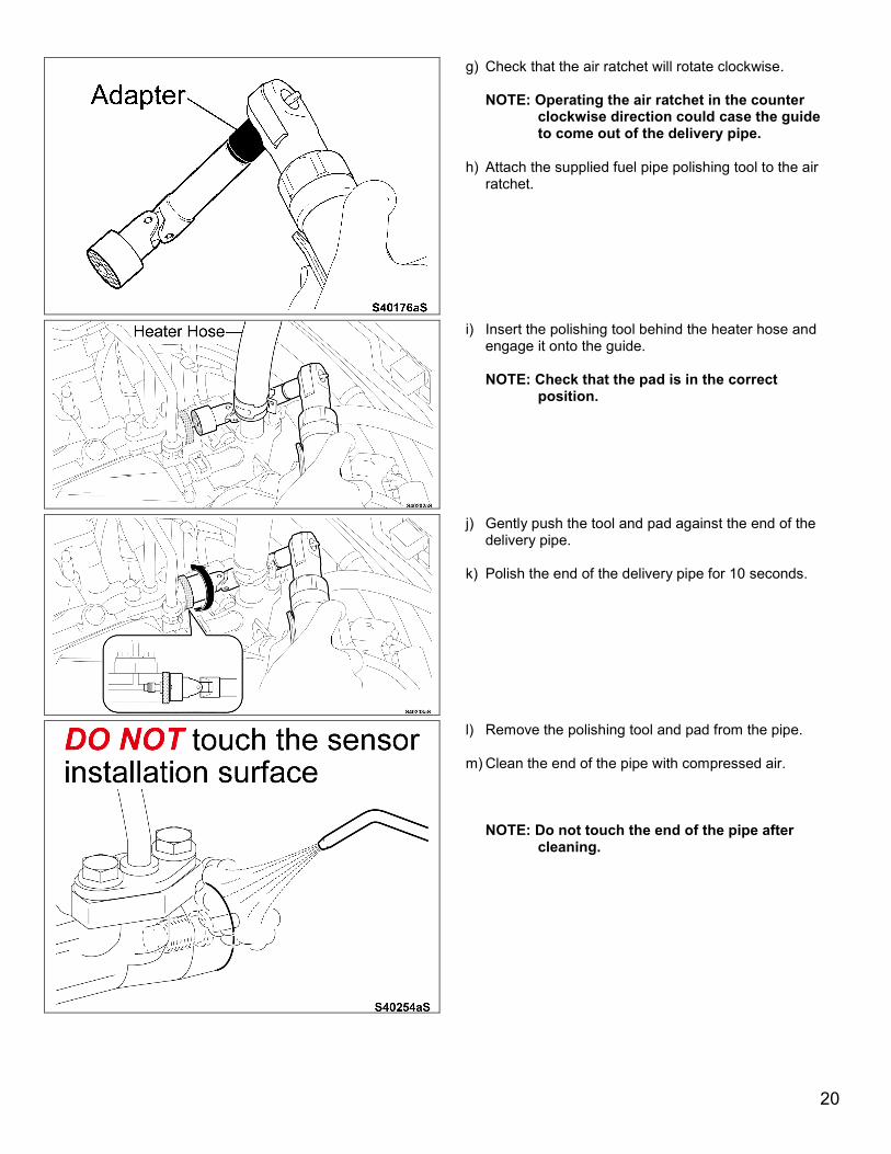
g) Check that the air ratchet will rotate clockwise. NOTE: Operating the air ratchet in the counter
clockwise direction could case the guide to come out of the delivery pipe.
h) Attach the supplied fuel pipe polishing tool to the air
ratchet.
i) Insert the polishing tool behind the heater hose and engage it onto the guide.
NOTE: Check that the pad is in the correct
position.
j) Gently push the tool and pad against the end of the delivery pipe.
k) Polish the end of the delivery pipe for 10 seconds.
l) Remove the polishing tool and pad from the pipe.
m) Clean the end of the pipe with compressed air.
NOTE: Do not touch the end of the pipe after
cleaning.
20
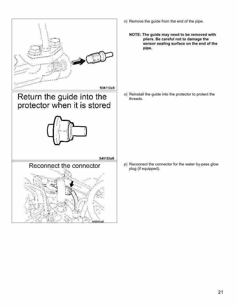
n) Remove the guide from the end of the pipe.
NOTE: The guide may need to be removed with pliers. Be careful not to damage the sensor sealing surface on the end of the pipe.
o) Reinstall the guide into the protector to protect the threads.
p) Reconnect the connector for the water by-pass glow plug (if equipped).
21
VII. REINSTALL THE FUEL PRESSURE SENSOR
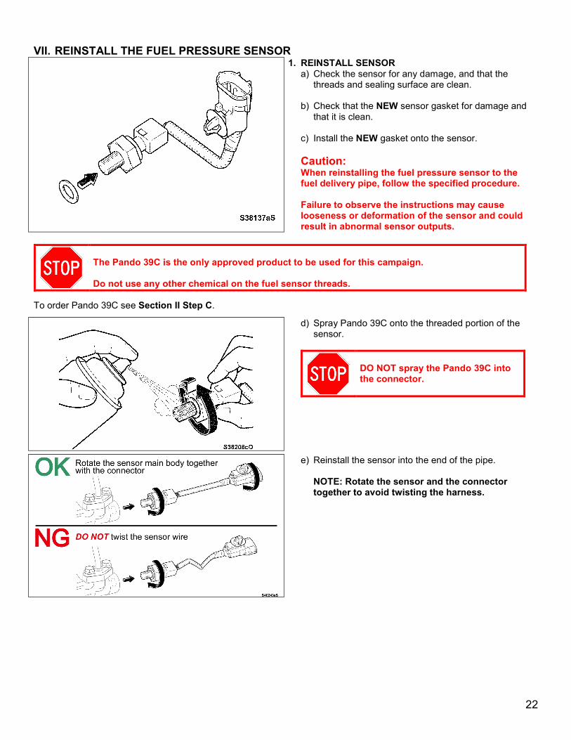
1. REINSTALL SENSOR a) Check the sensor for any damage, and that the
threads and sealing surface are clean.
b) Check that the NEW sensor gasket for damage and that it is clean.
c) Install the NEW gasket onto the sensor.
Caution: When reinstalling the fuel pressure sensor to the fuel delivery pipe, follow the specified procedure.
Failure to observe the instructions may cause looseness or deformation of the sensor and could result in abnormal sensor outputs.
The Pando 39C is the only approved product to be used for this campaign. Do not use any other chemical on the fuel sensor threads.
To order Pando 39C see Section II Step C.
d) Spray Pando 39C onto the threaded portion of the sensor.
DO NOT spray the Pando 39C into the connector.
e) Reinstall the sensor into the end of the pipe. NOTE: Rotate the sensor and the connector together to avoid twisting the harness.
22
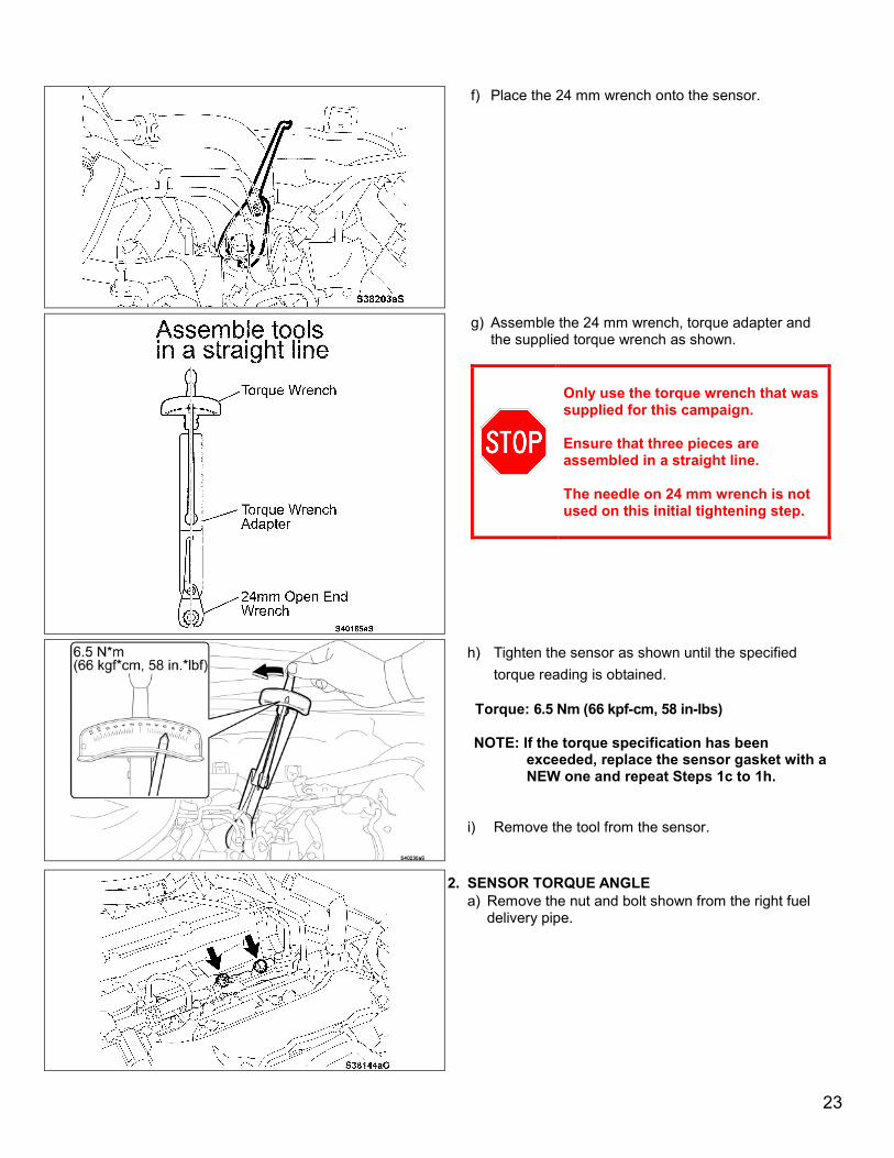
f) Place the 24 mm wrench onto the sensor.
g) Assemble the 24 mm wrench, torque adapter and the supplied torque wrench as shown.
Only use the torque wrench that was supplied for this campaign. Ensure that three pieces are assembled in a straight line. The needle on 24 mm wrench is not used on this initial tightening step.
h) Tighten the sensor as shown until the specified torque reading is obtained.
Torque: 6.5 Nm (66 kpf-cm, 58 in-lbs)
NOTE: If the torque specification has been
exceeded, replace the sensor gasket with a NEW one and repeat Steps 1c to 1h.
i) Remove the tool from the sensor.
2. SENSOR TORQUE ANGLE a) Remove the nut and bolt shown from the right fuel
delivery pipe.
23
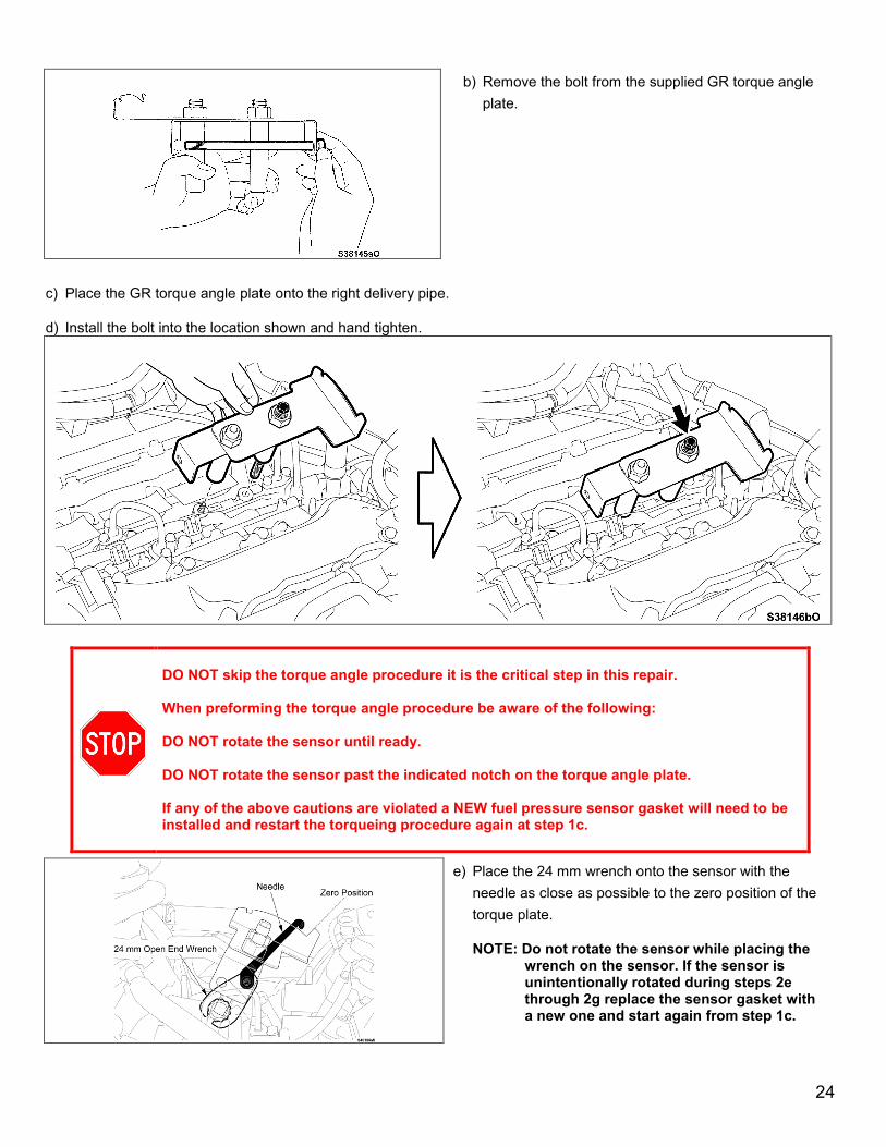
b) Remove the bolt from the supplied GR torque angle plate.
c) Place the GR torque angle plate onto the right delivery pipe.
d) Install the bolt into the location shown and hand tighten.
DO NOT skip the torque angle procedure it is the critical step in this repair. When preforming the torque angle procedure be aware of the following: DO NOT rotate the sensor until ready. DO NOT rotate the sensor past the indicated notch on the torque angle plate. If any of the above cautions are violated a NEW fuel pressure sensor gasket will need to be installed and restart the torqueing procedure again at step 1c.
e) Place the 24 mm wrench onto the sensor with the needle as close as possible to the zero position of the torque plate.
NOTE: Do not rotate the sensor while placing the
wrench on the sensor. If the sensor is unintentionally rotated during steps 2e through 2g replace the sensor gasket with a new one and start again from step 1c.
24

f) Attach the torque wrench adapter to the 24 mm wrench.
NOTE: Make sure that the torque adaptor does not hide the needle on the 24 mm wrench.
g) Lightly push and hold the torque adapter as shown to eliminate any play but do not rotate the sensor.
25
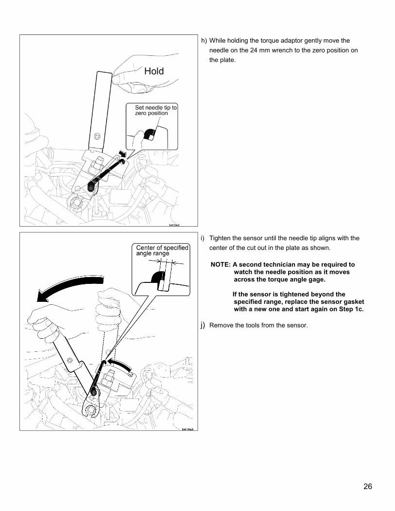
h) While holding the torque adaptor gently move the needle on the 24 mm wrench to the zero position on the plate.
i) Tighten the sensor until the needle tip aligns with the center of the cut out in the plate as shown.
NOTE: A second technician may be required to
watch the needle position as it moves across the torque angle gage.
If the sensor is tightened beyond the specified range, replace the sensor gasket with a new one and start again on Step 1c.
j) Remove the tools from the sensor.
26

k) Remove the bolt shown and remove the plate.
l) Return the bolt to its storage location on the plate.
m) Reinstall the bolt and nut for the right fuel delivery pipe. Torque: 26 Nm (265 kpf-cm, 19 ft-lbs)
n) Return the clamp for the heater hose to its original position if necessary.
27
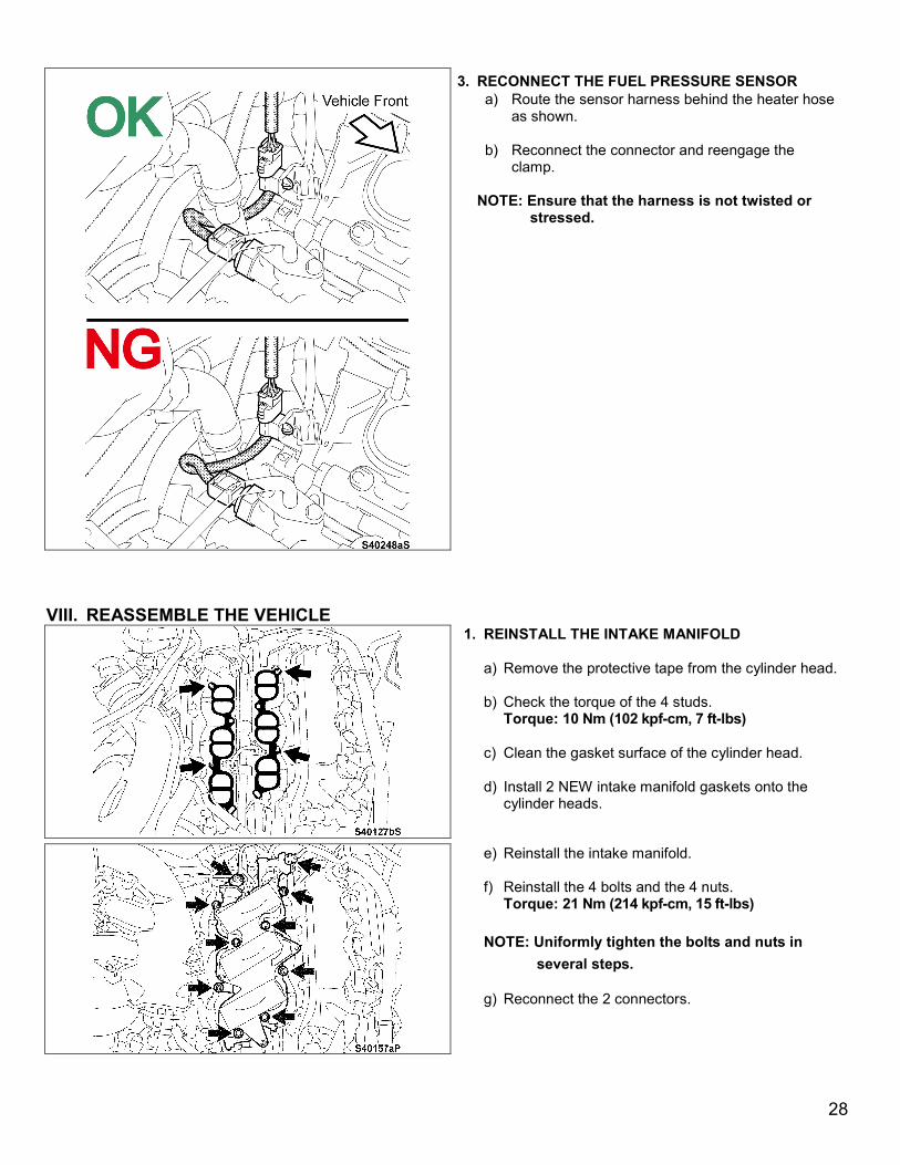
3. RECONNECT THE FUEL PRESSURE SENSOR a) Route the sensor harness behind the heater hose
as shown.
b) Reconnect the connector and reengage the clamp.
NOTE: Ensure that the harness is not twisted or stressed.
VIII. REASSEMBLE THE VEHICLE
1. REINSTALL THE INTAKE MANIFOLD
a) Remove the protective tape from the cylinder head.
b) Check the torque of the 4 studs. Torque: 10 Nm (102 kpf-cm, 7 ft-lbs)
c) Clean the gasket surface of the cylinder head.
d) Install 2 NEW intake manifold gaskets onto the cylinder heads.
e) Reinstall the intake manifold.
f) Reinstall the 4 bolts and the 4 nuts. Torque: 21 Nm (214 kpf-cm, 15 ft-lbs)
NOTE: Uniformly tighten the bolts and nuts in
several steps.
g) Reconnect the 2 connectors.
28
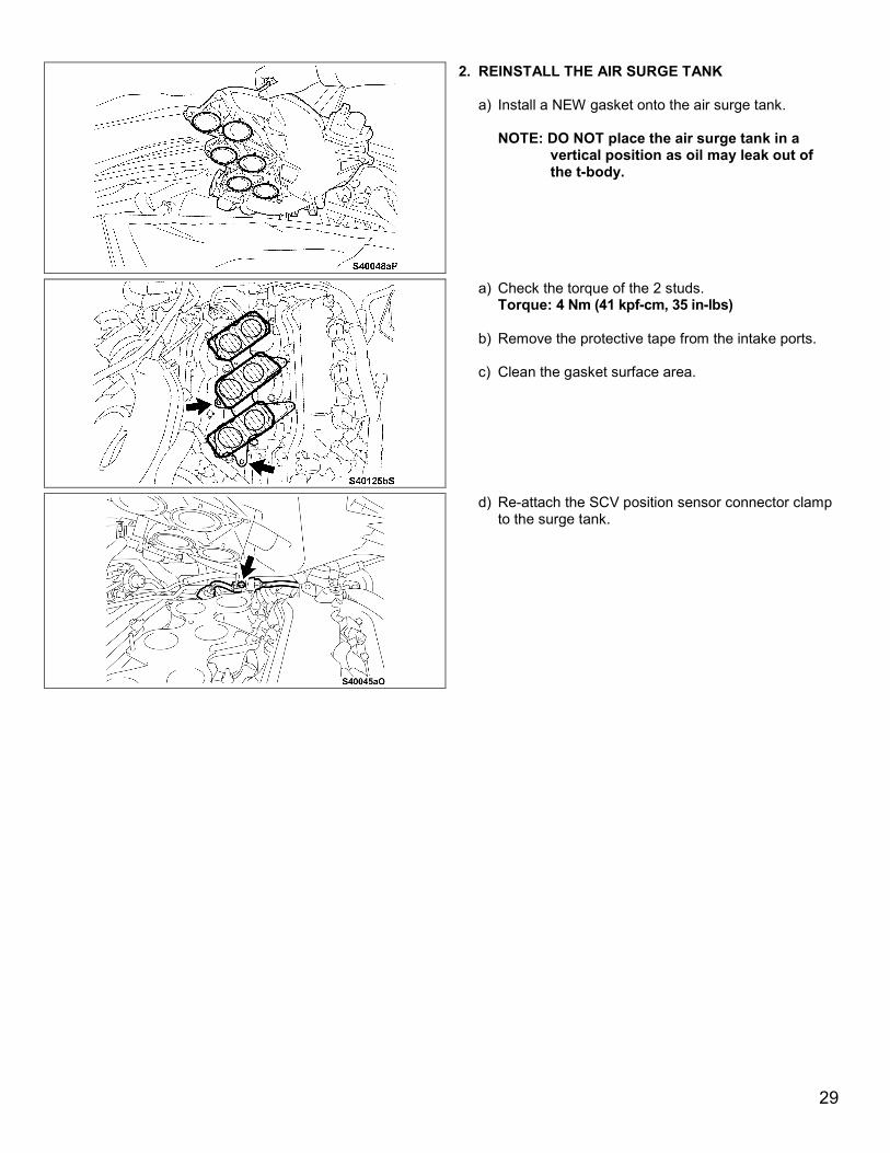
2. REINSTALL THE AIR SURGE TANK
a) Install a NEW gasket onto the air surge tank. NOTE: DO NOT place the air surge tank in a
vertical position as oil may leak out of the t-body.
a) Check the torque of the 2 studs. Torque: 4 Nm (41 kpf-cm, 35 in-lbs)
b) Remove the protective tape from the intake ports.
c) Clean the gasket surface area.
d) Re-attach the SCV position sensor connector clamp to the surge tank.
29
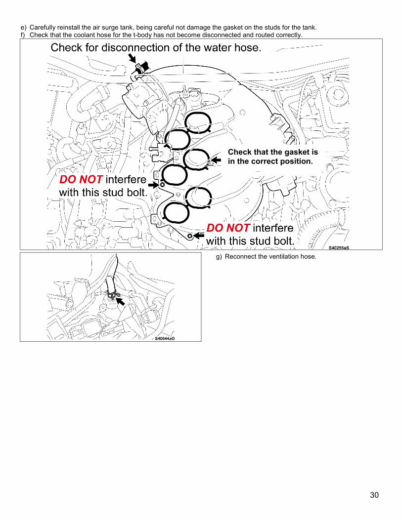
e) Carefully reinstall the air surge tank, being careful not damage the gasket on the studs for the tank. f) Check that the coolant hose for the t-body has not become disconnected and routed correctly.
g) Reconnect the ventilation hose.
Check that the gasket is in the correct position.
30
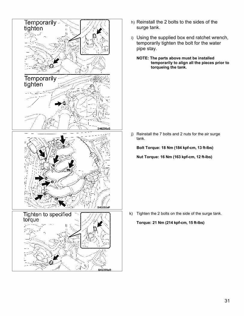
h) Reinstall the 2 bolts to the sides of the surge tank.
i) Using the supplied box end ratchet wrench,
temporarily tighten the bolt for the water pipe stay.
NOTE: The parts above must be installed temporarily to align all the pieces prior to torqueing the tank.
j) Reinstall the 7 bolts and 2 nuts for the air surge tank.
Bolt Torque: 18 Nm (184 kpf-cm, 13 ft-lbs)
Nut Torque: 16 Nm (163 kpf-cm, 12 ft-lbs)
k) Tighten the 2 bolts on the side of the surge tank.
Torque: 21 Nm (214 kpf-cm, 15 ft-lbs)
31
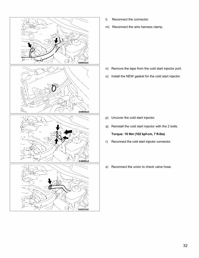
l) Reconnect the connector.
m) Reconnect the wire harness clamp.
n) Remove the tape from the cold start injector port.
o) Install the NEW gasket for the cold start injector.
p) Uncover the cold start injector.
q) Reinstall the cold start injector with the 2 bolts.
Torque: 10 Nm (102 kpf-cm, 7 ft-lbs) r) Reconnect the cold start injector connector.
s) Reconnect the union to check valve hose.
32
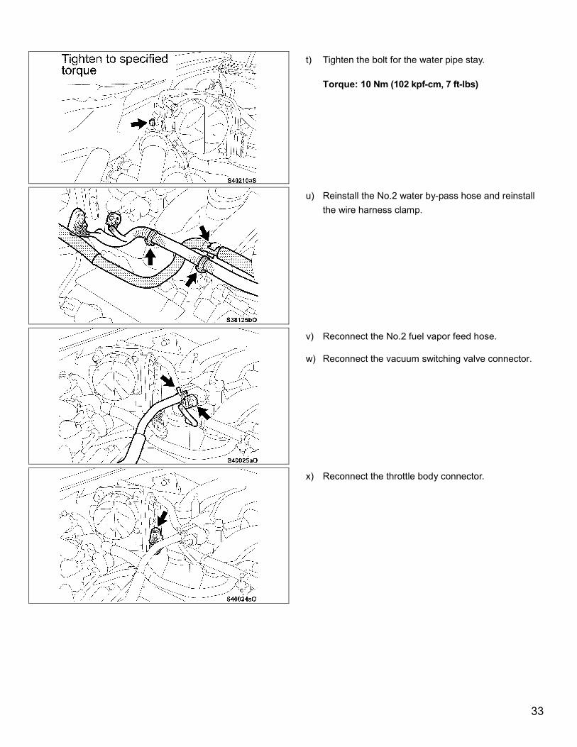
t) Tighten the bolt for the water pipe stay.
Torque: 10 Nm (102 kpf-cm, 7 ft-lbs)
u) Reinstall the No.2 water by-pass hose and reinstall the wire harness clamp.
v) Reconnect the No.2 fuel vapor feed hose.
w) Reconnect the vacuum switching valve connector.
x) Reconnect the throttle body connector.
33
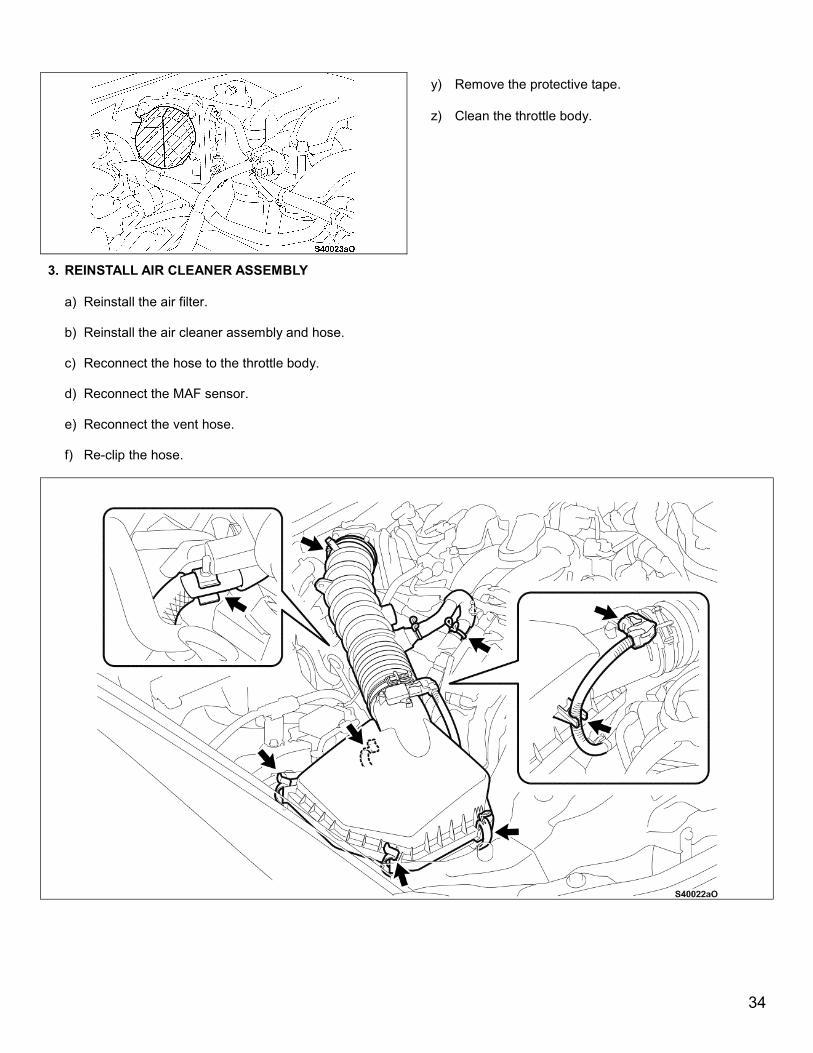
y) Remove the protective tape.
z) Clean the throttle body.
3. REINSTALL AIR CLEANER ASSEMBLY
a) Reinstall the air filter.
b) Reinstall the air cleaner assembly and hose.
c) Reconnect the hose to the throttle body.
d) Reconnect the MAF sensor.
e) Reconnect the vent hose.
f) Re-clip the hose.
34
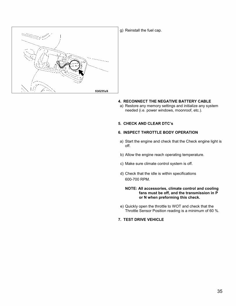
g) Reinstall the fuel cap.
4. RECONNECT THE NEGATIVE BATTERY CABLE
a) Restore any memory settings and initialize any system needed (i.e. power windows, moonroof, etc.).
5. CHECK AND CLEAR DTC’s
6. INSPECT THROTTLE BODY OPERATION
a) Start the engine and check that the Check engine light is off.
b) Allow the engine reach operating temperature.
c) Make sure climate control system is off.
d) Check that the idle is within specifications
600-700 RPM.
NOTE: All accessories, climate control and cooling fans must be off, and the transmission in P or N when preforming this check.
e) Quickly open the throttle to WOT and check that the
Throttle Sensor Position reading is a minimum of 60 %.
7. TEST DRIVE VEHICLE
35

8. REINSTALL ENGINE ROOM COVERS
◄ VERIFY REPAIR QUALITY ►
- Clear DTC’s - No fuel leaks or fuel smell
If you have any questions regarding this recall, please contact your regional representative.
IX. APPENDIX
CAMPAIGN DESIGNATION DECODER
C 0 J
Year Campaign is Launched
8 = 20089 = 2009A = 2010B = 2011C = 2012 D = 2013E = 2014F = 2015
Etc...
Repair Phase
1st Campaign = A2nd Campaign = B3rd Campaign = C4th Campaign = D5th Campaign = E6th Campaign = F7th Campaign = G8th Campaign = H9th Campaign = I
Etc...
Current Campaign Letter for this year
0 = Remedy1 = Interim (Remedy not yet available) “1”
will change to “0” when the Remedy is
available
Examples: A0D = Launched in 2010, Remedy Phase, 4th Campaign Launched in 2010 B1E = Launched in 2011, Interim Phase, 5rd Campaign Launched in 2011 C1C = Launched in 2012, Interim Phase, 3rd Campaign Launched in 2012
X. REMOVED PARTS As required by Federal Regulations, please make sure all recalled parts (original parts) removed from the vehicle are disposed of in a manner in which they will not be reused, unless requested for parts recovery return.
36