technical instructions for safety recall f0l …
TRANSCRIPT
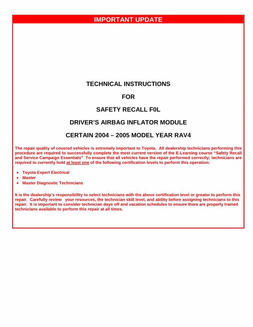
IMPORTANT UPDATE
TECHNICAL INSTRUCTIONS
FOR
SAFETY RECALL F0L
DRIVER’S AIRBAG INFLATOR MODULE
CERTAIN 2004 – 2005 MODEL YEAR RAV4
The repair quality of covered vehicles is extremely important to Toyota. All dealership technicians performing this procedure are required to successfully complete the most current version of the E-Learning course “Safety Recall and Service Campaign Essentials” To ensure that all vehicles have the repair performed correctly; technicians are required to currently hold at least one of the following certification levels to perform this operation: • Toyota Expert Electrical • Master • Master Diagnostic Technicians
It is the dealership’s responsibility to select technicians with the above certification level or greater to perform this repair. Carefully review your resources, the technician skill level, and ability before assigning technicians to this repair. It is important to consider technician days off and vacation schedules to ensure there are properly trained technicians available to perform this repair at all times.
2
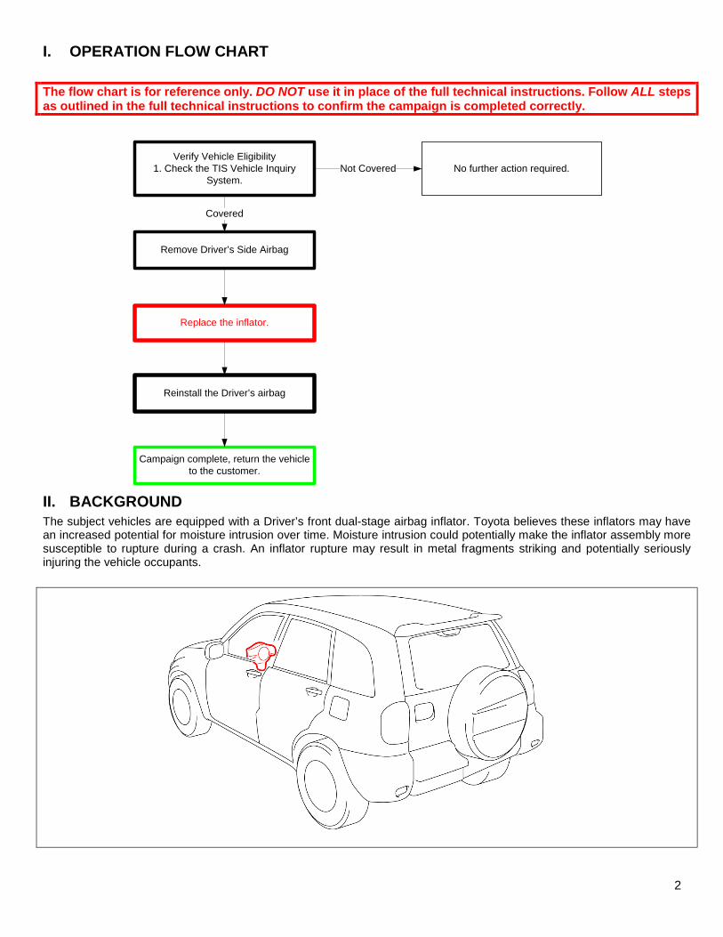
I. OPERATION FLOW CHART
The flow chart is for reference only. DO NOT use it in place of the full technical instructions. Follow ALL steps as outlined in the full technical instructions to confirm the campaign is completed correctly.
Verify Vehicle Eligibility
1. Check the TIS Vehicle Inquiry System.
No further action required.Not Covered
Campaign complete, return the vehicle to the customer.
Covered
Replace the inflator.
Reinstall the Driver’s airbag
Remove Driver’s Side Airbag
II. BACKGROUND
The subject vehicles are equipped with a Driver’s front dual-stage airbag inflator. Toyota believes these inflators may have an increased potential for moisture intrusion over time. Moisture intrusion could potentially make the inflator assembly more susceptible to rupture during a crash. An inflator rupture may result in metal fragments striking and potentially seriously injuring the vehicle occupants.

3
III. IDENTIFICATION OF AFFECTED VEHICLES
• Check the TIS Vehicle Inquiry System to confirm the VIN is involved in this Safety Recall, and that the campaign has not already been completed prior to dealer shipment or by another dealer.
• TMS warranty will not reimburse dealers for repairs conducted on vehicles that are not affected or were completed by another dealer.
IV. PREPARATION A. PARTS
Only one inflator kit is required per vehicle, ensure you pick the correct part number for your location and model year so that the correct return shipping information is included.
Applicable for: The Continental U.S. 48 States Only
Model Part Number Part Description Quantity RAV 4 04005-08442 Driver’s Side Inflator Kit 1
*The kit above includes the following parts.
Inflator 1 Self Locking Nut 4
Applicable for: Alaska, Hawaii and USTT Locations Only
Model Part Number Part Description Quantity RAV 4 04005-08342 Driver’s Side Inflator Kit 1
*The kit above includes the following parts.
Inflator 1 Self Locking Nut 4
B. TOOLS & EQUIPMENT
• Standard hand tools • Torque wrench • Techstream
OPTIONAL SST – This is an essential special service tool that the dealership should have. This tool is not mandatory when performing this repair.
Part Number Part Name Quantity 09890-47010-01 Anti-Static Mat Set 1
F0L CAMPAIGN TOOLS – Scanners was previously provided to the dealership for campaigns D0F and F0J. The scanner is required when performing this repair.
Image Name Quantity
Barcode Scanner (D0F & F0J) 1
NOTE: The scanner will need to be updated the first time it is used to scan the RAV 4 airbag barcodes. Refer to Section XIII Appendix for more information.
4
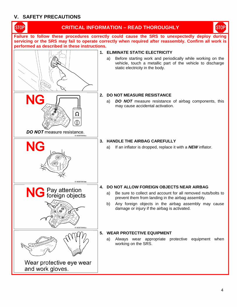
V. SAFETY PRECAUTIONS
CRITICAL INFORMATION – READ THOROUGHLY
Failure to follow these procedures correctly could cause the SRS to unexpectedly deploy during servicing or the SRS may fail to operate correctly when required after reassembly. Confirm all work is performed as described in these instructions.
1. ELIMINATE STATIC ELECTRICITY
a) Before starting work and periodically while working on the vehicle, touch a metallic part of the vehicle to discharge static electricity in the body.
2. DO NOT MEASURE RESISTANCE
a) DO NOT measure resistance of airbag components, this may cause accidental activation.
3. HANDLE THE AIRBAG CAREFULLY
a) If an inflator is dropped, replace it with a NEW inflator.
4. DO NOT ALLOW FOREIGN OBJECTS NEAR AIRBAG
a) Be sure to collect and account for all removed nuts/bolts to prevent them from landing in the airbag assembly.
b) Any foreign objects in the airbag assembly may cause damage or injury if the airbag is activated.
5. WEAR PROTECTIVE EQUIPMENT
a) Always wear appropriate protective equipment when working on the SRS.

5
VI. COMPONENTS
VII. SRS SYSTEM HEALTH CHECK
1. PERFORM A HEALTH CHECK
a) Confirm the Techstream is connected to the dealership’s internet.
b) When launching the Techstream software the VIN MUST be entered manually.
NOTE: All letters of the VIN MUST be entered in ALL CAPS, or the VIN will need to be reentered when running the diagnostic report.
c) Perform a health check. Note: The VIN may auto populate on the later model year
vehicles, if this happens DO NOT change the VIN.
6
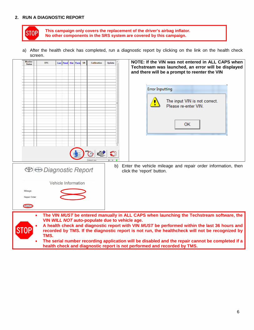
2. RUN A DIAGNOSTIC REPORT
This campaign only covers the replacement of the driver’s airbag inflator. No other components in the SRS system are covered by this campaign.
a) After the health check has completed, run a diagnostic report by clicking on the link on the health check screen.
NOTE: If the VIN was not entered in ALL CAPS when Techstream was launched, an error will be displayed and there will be a prompt to reenter the VIN
b) Enter the vehicle mileage and repair order information, then click the ‘report’ button.
• The VIN MUST be entered manually in ALL CAPS when launching the Techstream software, the VIN WILL NOT auto-populate due to vehicle age.
• A health check and diagnostic report with VIN MUST be performed within the last 36 hours and recorded by TMS. If the diagnostic report is not run, the healthcheck will not be recognized by TMS.
• The serial number recording application will be disabled and the repair cannot be completed if a health check and diagnostic report is not performed and recorded by TMS.

7
VIII. WORK AREA PREPARATION
CRITICAL INFORMATION – READ THOROUGHLY
The anti-static mat set that is an essential SST may be available at your dealership and is optional to use during inflator replacement. If the anti-static kit is not available, before starting work and periodically while working on the vehicle, touch a metallic part of the vehicle to discharge static electricity in the body.
If the anti-static kit is not available, before starting work and periodically while working on the vehicle, touch a metallic part of the vehicle to discharge static electricity in the body.
8
IX. DRIVERS AIRBAG REMOVAL
1. DISCONNECT THE NEGATIVE BATTERY CABLE
• Wait at least 90 seconds after disconnecting the cable from the negative battery terminal to prevent airbag and seat belt pre-tensioner deployment.
• Follow all precautions as outlined on TIS before servicing the SRS system.
2. REMOVE THE DRIVERS AIRBAG
a) Refer to TIS for instructions on airbag removal:
RAV4 2004 2005
b) Use low pressure shop air to clean any debris around the inflator.
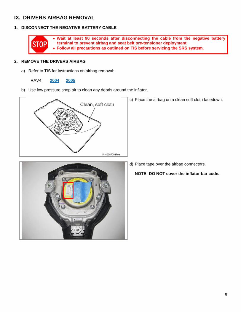
c) Place the airbag on a clean soft cloth facedown.
d) Place tape over the airbag connectors.
NOTE: DO NOT cover the inflator bar code.

9
X. RECORD AIRBAG AND INFLATOR SERIAL NUMBERS
1. LAUNCH THE SERIAL NUMBER RECORDING APPLICATION
• The AIRBAG ASSEMBLY, ORIGINAL INFLATOR, and NEW INFLATOR serial numbers MUST be recorded using the barcode scanner (provided at the launch of SSC D0F & F0J).
• The barcode scanner application MUST be completed on every vehicle. These numbers MUST be included on every warranty claim that is submitted for inflator module replacement or the claim may be subject to debit.
• The technician performing the work MUST have valid TIS login credentials and an internet connection to perform the inspection and scanning process.
a) Log in to TIS and input the VIN of the vehicle in the Vehicle Inquiry tab.
b) Confirm the VIN is applicable and that the campaign has not been completed.
c) Click on the link to launch the serial number recording application.
d) Reenter TIS password in the serial number recorder application.
NOTE: The person logged-in to TIS MUST be the person performing the repair.
e) Record the vehicle mileage into the serial number recording application.
NOTE: • A task status screen will populate next and at other intervals
during the repair. This screen will indicate if the inflator was replaced or in some limited cases that the entire airbag assembly was replaced. Click ‘next’ to proceed to the next step. This information will be used for record keeping by TMS.
• If this screen indicates that the inflator has already been replaced on this VIN, there is no need to perform the campaign again.
E04

10
2. CONNECT THE BARCODE SCANNER
a) Connect the barcode scanner to the USB port on the Techstream.
b) The scanner will automatically connect and a beep will be heard when the scanner is ready.
NOTE: • The scanner works best in low light conditions. • Always hold the scanner directly in front of and parallel to the barcode label.
The scanner will need to be updated the first time it is used to scan the RAV 4 airbag barcodes. Refer to Section XIII Appendix for more information.
3. SCAN THE AIRBAG SERIAL NUMBER
NOTE: Best practice is to scan all 3 components at the same time.
1. Airbag
2. Old Inflator
3. New Inflator
ATTENTION: This information is CRITICAL
a) Scan the AIRBAG ASSEMBLY serial number 2 times. 1) Confirm the cursor is in the first serial
number box then scan the serial.
2) Position the cursor in the second serial number box then scan the serial.
b) Click next.
c) Proceed to Step 4.
NOTE: • If both serial numbers that are entered do not
match, confirm and reenter. • If the airbag serial number is missing or
unreadable proceed to AIRBAG SERIAL NUMBER IS MISSING OR UNREADABLE.
AIRBAG SERIAL NUMBER IDENTIFICATION • The airbag serial number is ALWAYS the 12
DIGITS located between the asterisks.
Airbag Serial Number Label Example
The AIRBAG ASSEMBLY serial number and the INFLATOR serial number are DIFFERENT. The AIRBAG ASSEMBLY serial number MUST be recorded prior to replacement.

11
NOTE: If the wrong bar code is scanned the following message will appear.

12
AIRBAG SERIAL NUMBER IS MISSING OR IS UNREADABLE
If the airbag serial number and barcode are not legible or are not present, check the box in the application indicating the serial number is not legible and contact your regional representative.
a) If the airbag serial number cannot be scanned or is not present check the box as shown below and repalce the airbag assembly.
Checking this box requires Air Bag Assembly replacement. **Note** Contact your region in the event
that you are unable to read the serial number. DO NOT ATTEMPT TO INSTALL INFLATOR
The following screen will also appear when checking the box

13
b) After the Region approves the Airbag Assembly replacement and the new part is received, scan the NEW
airbag barcode in the Serial Number Recording Application. c) Select next to go to receive the Warranty Authorization # to be included in the warranty claim.
The new AIRBAG ASSEMBLY serial number MUST be recorded prior to reinstallation to track the airbag assembly to the vehicle.
14
ENSURE YOU ENTER BOTH THE OLD AND NEW INFLATOR SERIAL NUMBERS IN THE APPROPRIATE SPOT OF THE APPLICATION
-DO NOT ENTER THE AIRBAG SERIAL NUMBER FOR THIS STEP-
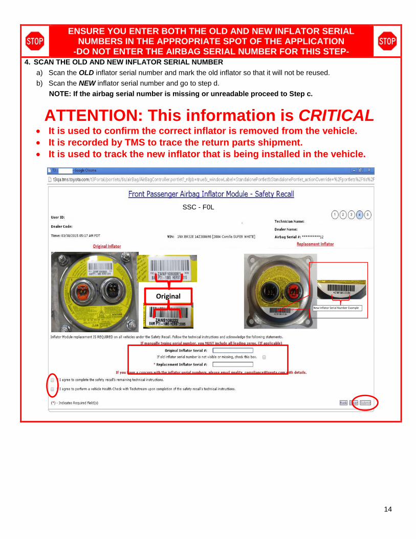
4. SCAN THE OLD AND NEW INFLATOR SERIAL NUMBER
a) Scan the OLD inflator serial number and mark the old inflator so that it will not be reused.
b) Scan the NEW inflator serial number and go to step d.
NOTE: If the airbag serial number is missing or unreadable proceed to Step c.
ATTENTION: This information is CRITICAL • It is used to confirm the correct inflator is removed from the vehicle. • It is recorded by TMS to trace the return parts shipment. • It is used to track the new inflator that is being installed in the vehicle.
Original
New Inflator Serial Number Example
SSC - F0L
15
Old Inflator
New Inflator
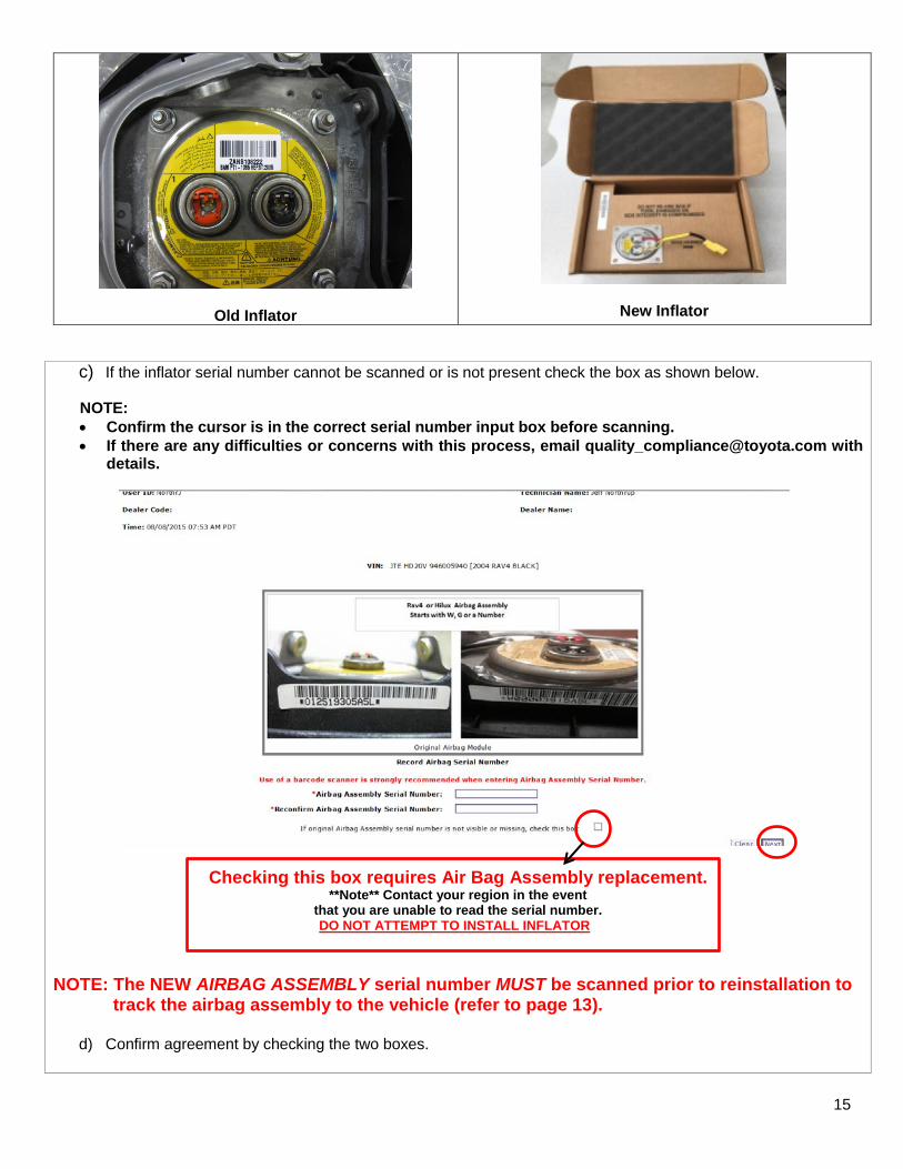
c) If the inflator serial number cannot be scanned or is not present check the box as shown below.
NOTE: • Confirm the cursor is in the correct serial number input box before scanning. • If there are any difficulties or concerns with this process, email [email protected] with
details.
Checking this box requires Air Bag Assembly replacement. **Note** Contact your region in the event
that you are unable to read the serial number. DO NOT ATTEMPT TO INSTALL INFLATOR
NOTE: The NEW AIRBAG ASSEMBLY serial number MUST be scanned prior to reinstallation to track the airbag assembly to the vehicle (refer to page 13).
d) Confirm agreement by checking the two boxes.
16
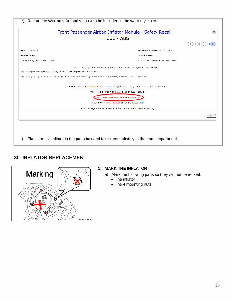
e) Record the Warranty Authorization # to be included in the warranty claim.
f) Place the old inflator in the parts box and take it immediately to the parts department.
XI. INFLATOR REPLACEMENT
1. MARK THE INFLATOR
a) Mark the following parts so they will not be reused: • The inflator • The 4 mounting nuts

17
CRITICAL INFORMATION – READ THOROUGHLY
ALWAYS keep as much of your body as possible in front of the bracket when working on the airbag assembly.
Remember to periodically touch a metallic part of the vehicle to discharge static electricity in the body if the anti-static kit is not being used.
2. REMOVE THE SELF LOCKING NUTS
a) Remove and discard the 4 nuts.
NOTE: DO NOT use power tools.
3. REMOVE THE INFLATOR
a) Pull the inflator straight up from the airbag assembly and place
it on a safe work surface.
b) Place the old inflator in the box that the new inflator came in and return it to the parts department.
NOTE: The design differences from the original inflator and the replacement inflator.

18
4. INSTALL THE NEW INFLATOR
a) Check that all 4 studs are straight.
b) Straighten any studs that are bent.
c) Carefully guide the new inflator into the airbag assembly.
NOTE: Ensure that the bar code is facing the correct way.
d) Ensure that the inflator is fully seated in the airbag.
5. TORQUE THE NEW RETAINING NUTS
a) Install and tighten the NEW nuts evenly in two steps in an X pattern. Use a socket driver or torque wrench to tighten the nuts.
Torque: 7.0 N*M (71 kgf*cm, 62 in. lbf)
• There will be some resistance when tightening the nuts because they are self-locking, confirm the nuts are tightened correctly.
• DO NOT use a power tool, T-handle, or ratchet when tightening the nuts to avoid over torqueing.
Ensure that the bar code is facing the correct way.

19
6. INSPECT THE AIRBAG BEFORE INSTALLATION
a) Confirm that the inflator is oriented correctly.
• Bar code to the left.
b) The inflator is fully seated.
c) Confirm that the 4 NEW nuts are installed and tight.
XII. FRONT PASSENGER AIRBAG ASSEMBLY INSTALLATION
1. REINSTALL THE DRIVERS AIRBAG
a) Refer to TIS for instructions on airbag installation: RAV4 2004 2005
2. RECONNECT THE NEGATIVE BATTERY CABLE
3. PERFORM A HEALTH CHECK AND DIAGNOSTIC REPORT
4. CHECK HORN OPERATION
◄ VERIFY REPAIR QUALITY ► − Confirm all precautions are follow to ensure safety during the repair − Confirm the entire serial number checker application is completed and the warranty authorization # is
recorded on EVERY vehicle − Confirm the old inflator is handled safely and given to the appropriate parts professional for shipment
If you have any questions regarding this update, please contact your regional representative.

20
XIII. APPENDIX
A. SCANNER SET-UP Determine which scanner you need to update the Datalogic QD 2300 was provided at the launch of D0F and emits a red beam when the scanner is used. The Datalogic 2430 was provided at the launch of F0J and emits a blue beam when the scanner is used. (Datalogic QD 2300 provided at the launch of D0F) The scanner will need to have an application added for it to read the bar code on driver’s airbag. Preform the following steps to load the application on to the scanner. NOTE: This application only needs to be loaded once. a) Scanning the image below to enable code 93.
b) Scan the image below for enable any length for code 93.
c) The scanner is now ready to scan the airbag bar codes. Additional information can be found in the Datalogic Product Reference Guide. The Datalogic website is: http://www.datalogic.com/eng/support-services/automatic-data-capture/downloads/manuals-ma-3.html?search_prod=166

21
(Datalogic 2430 provided at the launch of F0J) The scanner will need to have an application added for it to read the bar code on driver’s airbag. Preform the following steps to load the application on to the scanner. NOTE: This application only needs to be loaded once.
a) Enter the programming mode by scanning the image below.
b) Scan the image below for Code 93.
c) Scan the image below to exit the programming mode.
d) The scanner is now ready to scan the airbag bar codes.
Additional information can be found in the Datalogic Product Reference Guide. The Datalogic website is: http://www.datalogic.com/eng/support-services/automatic-data-capture/downloads/manuals-ma-3.html?search_prod=612
B. CAMPAIGN DESIGNATION DECODER
C 0 T
Year Campaign is Launched
8 = 20089 = 2009A = 2010B = 2011C = 2012 D = 2013E = 2014F = 2015
Etc...
Repair Phase
1st Campaign = A2nd Campaign = B
Etc...
Current Campaign Letter for this year
0 = Remedy1 = Prelim/Interim
2 = Prelim/Interim for Phase 2 Vehicles(Remedy not yet
available) “1 or 2” will change to “0” when the
Remedy is available
C. CAMPAIGN PARTS DISPOSAL
ALL inflators that are removed from vehicles under this campaign MUST be packaged and shipped back to the inflator manufacturer following the manufacturer’s instructions. The instructions can be found in the following locations: • Attached to the dealer letter • Included in the parts box • On the laminated aid that was provided at the launch of the campaign