technical data type cv & sv oil-immersed on-load tap · pdf filetechnical data type cv...
TRANSCRIPT

SHANGHAI HUAMING POWER EQUIPMENT CO., LTD.
TECHNICAL DATATYPE CV & SVOIL-IMMERSED ON-LOAD TAP CHANGERHM0.154.001
HM0.154.001
TYPE CV & SV OIL-IMMERSED ON-LOAD TAP CHANGER TECHNICAL DATA
1
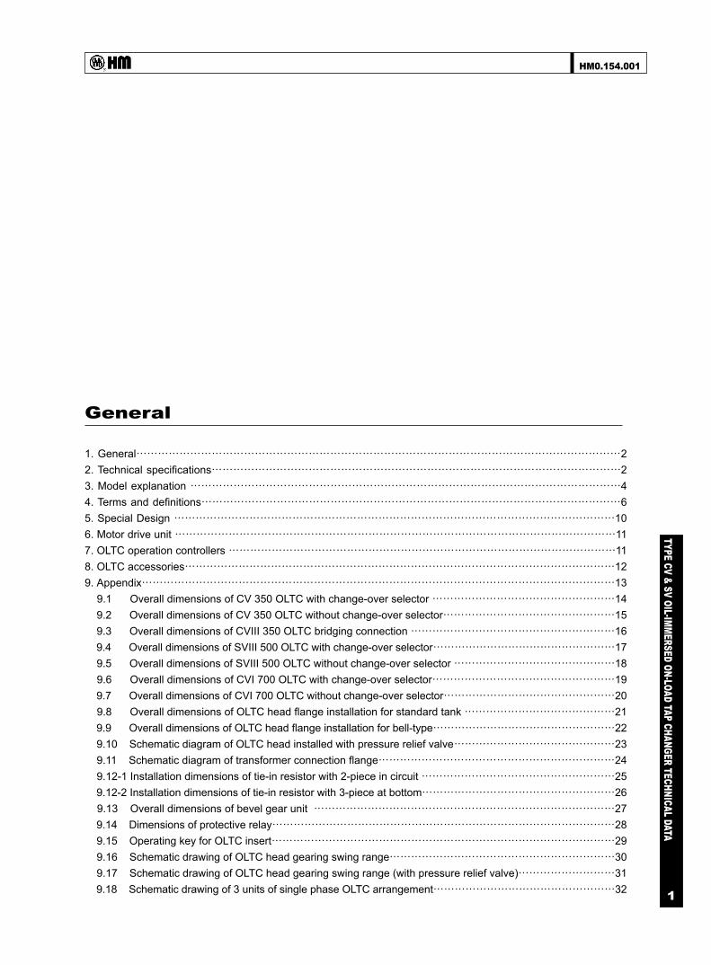
1. General⋯⋯⋯⋯⋯⋯⋯⋯⋯⋯⋯⋯⋯⋯⋯⋯⋯⋯⋯⋯⋯⋯⋯⋯⋯⋯⋯⋯⋯⋯⋯⋯⋯⋯⋯⋯⋯⋯⋯⋯⋯⋯⋯⋯⋯2 2. Technical specifications⋯⋯⋯⋯⋯⋯⋯⋯⋯⋯⋯⋯⋯⋯⋯⋯⋯⋯⋯⋯⋯⋯⋯⋯⋯⋯⋯⋯⋯⋯⋯⋯⋯⋯⋯⋯⋯⋯2 3. Model explanation ⋯⋯⋯⋯⋯⋯⋯⋯⋯⋯⋯⋯⋯⋯⋯⋯⋯⋯⋯⋯⋯⋯⋯⋯⋯⋯⋯⋯⋯⋯⋯⋯⋯⋯⋯⋯⋯⋯⋯⋯4 4. Terms and definitions⋯⋯⋯⋯⋯⋯⋯⋯⋯⋯⋯⋯⋯⋯⋯⋯⋯⋯⋯⋯⋯⋯⋯⋯⋯⋯⋯⋯⋯⋯⋯⋯⋯⋯⋯⋯⋯⋯⋯6 5. Special Design ⋯⋯⋯⋯⋯⋯⋯⋯⋯⋯⋯⋯⋯⋯⋯⋯⋯⋯⋯⋯⋯⋯⋯⋯⋯⋯⋯⋯⋯⋯⋯⋯⋯⋯⋯⋯⋯⋯⋯⋯⋯10 6. Motor drive unit ⋯⋯⋯⋯⋯⋯⋯⋯⋯⋯⋯⋯⋯⋯⋯⋯⋯⋯⋯⋯⋯⋯⋯⋯⋯⋯⋯⋯⋯⋯⋯⋯⋯⋯⋯⋯⋯⋯⋯⋯⋯11 7. OLTC operation controllers ⋯⋯⋯⋯⋯⋯⋯⋯⋯⋯⋯⋯⋯⋯⋯⋯⋯⋯⋯⋯⋯⋯⋯⋯⋯⋯⋯⋯⋯⋯⋯⋯⋯⋯⋯⋯11 8. OLTC accessories⋯⋯⋯⋯⋯⋯⋯⋯⋯⋯⋯⋯⋯⋯⋯⋯⋯⋯⋯⋯⋯⋯⋯⋯⋯⋯⋯⋯⋯⋯⋯⋯⋯⋯⋯⋯⋯⋯⋯⋯12 9. Appendix⋯⋯⋯⋯⋯⋯⋯⋯⋯⋯⋯⋯⋯⋯⋯⋯⋯⋯⋯⋯⋯⋯⋯⋯⋯⋯⋯⋯⋯⋯⋯⋯⋯⋯⋯⋯⋯⋯⋯⋯⋯⋯⋯⋯13 9.1 Overall dimensions of CV 350 OLTC with change-over selector ⋯⋯⋯⋯⋯⋯⋯⋯⋯⋯⋯⋯⋯⋯⋯⋯⋯14 9.2 Overall dimensions of CV 350 OLTC without change-over selector⋯⋯⋯⋯⋯⋯⋯⋯⋯⋯⋯⋯⋯⋯⋯⋯15 9.3 Overall dimensions of CVIII 350 OLTC bridging connection ⋯⋯⋯⋯⋯⋯⋯⋯⋯⋯⋯⋯⋯⋯⋯⋯⋯⋯⋯16 9.4 Overall dimensions of SVIII 500 OLTC with change-over selector⋯⋯⋯⋯⋯⋯⋯⋯⋯⋯⋯⋯⋯⋯⋯⋯⋯17 9.5 Overall dimensions of SVIII 500 OLTC without change-over selector ⋯⋯⋯⋯⋯⋯⋯⋯⋯⋯⋯⋯⋯⋯⋯18 9.6 Overall dimensions of CVI 700 OLTC with change-over selector⋯⋯⋯⋯⋯⋯⋯⋯⋯⋯⋯⋯⋯⋯⋯⋯⋯19 9.7 Overall dimensions of CVI 700 OLTC without change-over selector⋯⋯⋯⋯⋯⋯⋯⋯⋯⋯⋯⋯⋯⋯⋯⋯20 9.8 Overall dimensions of OLTC head flange installation for standard tank ⋯⋯⋯⋯⋯⋯⋯⋯⋯⋯⋯⋯⋯⋯21 9.9 Overall dimensions of OLTC head flange installation for bell-type⋯⋯⋯⋯⋯⋯⋯⋯⋯⋯⋯⋯⋯⋯⋯⋯⋯22 9.10 Schematic diagram of OLTC head installed with pressure relief valve⋯⋯⋯⋯⋯⋯⋯⋯⋯⋯⋯⋯⋯⋯⋯23 9.11 Schematic diagram of transformer connection flange⋯⋯⋯⋯⋯⋯⋯⋯⋯⋯⋯⋯⋯⋯⋯⋯⋯⋯⋯⋯⋯⋯24 9.12-1 Installation dimensions of tie-in resistor with 2-piece in circuit ⋯⋯⋯⋯⋯⋯⋯⋯⋯⋯⋯⋯⋯⋯⋯⋯⋯⋯25 9.12-2 Installation dimensions of tie-in resistor with 3-piece at bottom⋯⋯⋯⋯⋯⋯⋯⋯⋯⋯⋯⋯⋯⋯⋯⋯⋯⋯26 9.13 Overall dimensions of bevel gear unit ⋯⋯⋯⋯⋯⋯⋯⋯⋯⋯⋯⋯⋯⋯⋯⋯⋯⋯⋯⋯⋯⋯⋯⋯⋯⋯⋯⋯27 9.14 Dimensions of protective relay⋯⋯⋯⋯⋯⋯⋯⋯⋯⋯⋯⋯⋯⋯⋯⋯⋯⋯⋯⋯⋯⋯⋯⋯⋯⋯⋯⋯⋯⋯⋯⋯28 9.15 Operating key for OLTC insert⋯⋯⋯⋯⋯⋯⋯⋯⋯⋯⋯⋯⋯⋯⋯⋯⋯⋯⋯⋯⋯⋯⋯⋯⋯⋯⋯⋯⋯⋯⋯⋯29 9.16 Schematic drawing of OLTC head gearing swing range⋯⋯⋯⋯⋯⋯⋯⋯⋯⋯⋯⋯⋯⋯⋯⋯⋯⋯⋯⋯⋯30 9.17 Schematic drawing of OLTC head gearing swing range (with pressure relief valve)⋯⋯⋯⋯⋯⋯⋯⋯⋯31 9.18 Schematic drawing of 3 units of single phase OLTC arrangement⋯⋯⋯⋯⋯⋯⋯⋯⋯⋯⋯⋯⋯⋯⋯⋯⋯32
General
HM0.154.001
TYPE CV & SV OIL-IMMERSED ON-LOAD TAP CHANGER TECHNICAL DATA
2
1. General
CV & SV on-load tap changer (hereinafter referred to as CV or CV OLTC) is a selector switch type of OLTC, CV is applied for oil-immersed regulating transformer. The design of CV contact system is of rolling type dual resistor transition structure. CV is mounted on the top of the transformer tank via head flange, which is divided into two mounting models namely bell-type and standard tank.
CV OLTC is operated by motor drive unit through connection with head gear mechanism, driving shaft and bevel gear unit, it could be realized to operate OLTC locally or remotely.
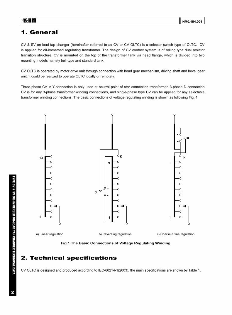
Three-phase CV in Y-connection is only used at neutral point of star connection transformer, 3-phase D-connection CV is for any 3-phase transformer winding connections, and single-phase type CV can be applied for any selectable transformer winding connections. The basic connections of voltage regulating winding is shown as following Fig. 1.
a) Linear regulation b) Reversing regulation
Fig.1 The Basic Connections of Voltage Regulating Winding
c) Coarse & fine regulation
2. Technical specifications
CV OLTC is designed and produced according to IEC-60214-1(2003), the main specifications are shown by Table 1.

HM0.154.001
TYPE CV & SV OIL-IMMERSED ON-LOAD TAP CHANGER TECHNICAL DATA
3
Table 1 CV & SV Series OLTC Main Technical Specifications
* The max through current should be decreased to 350A and 300A, when the switching capacity are 525kVA and 420kVA
Model OLTC models CVIII350Y CVIII350D CV I 350 SVIII500Y SVIII500D CV700
1 Max.rated through-current (A) 350 500 700
2 Rated frequency (Hz) 50 or 60
3 Number of poles 3 3 1 3 3 1
4 Connection application Y-in the neutral, D and single pole- in any part of the winding
5 Short-circuit current test (kA)
Thermic (3 secs.) 5 7 10
Dynamic (peak value) 12.5 17.5 25
6Max.Step
voltage (V)
10 contacts 1500 1500 1500
12 contacts 1400 1400 1400
14 contacts 1000 - 1000
7Rated Step
capacity (kVA)
10 contacts 525 400~525* 660
12 contacts 420 325~420* 520
14contacts 350 - 450
8Max.operating
positions
Without change-over selector 14 12 14
With change-over selector 27 23 27
9Insulationto ground
(kV)
Highest voltage for equipment Um 40.5 72.5
Rated separate source ACwithstand voltage(kV/50Hz,1min 85 140
Rated lightning impulsewithstand voltage (kV,1.2/50μs) 225 350
10 Rated withstand voltages of the internal insulation See section 4.6
12 Mechancial life not less than 800,000 operations
13 Electrical life not less than 200,000 operations
14Oil
compartment
Operating pressure 0.03MPa
Test pressure 0.08MPa, without any leakage for 24 hours
Over pressue protection bursting cap bursts at 300kPa±20% overpressure
Protection relay Setting oil flow speed 1.0m/s±10%
15 Equipped with motor drive unit model SHM-III or CMA9, CMA7
16 OLTC models CVIII350Y CVIII350D CV I 350 SVIII500Y SVIII500D CV I 700
17 Weight ( approx.kg ) 140 150 120 190 200 130
18Oil displacement
volume(approx. dm3)
Without change-over selector 135 185 85 205 240 120
With change-over selector 165 220 115 235 275 150
19
Volume of oilfilling Vs and oilconservator DV
(approx.dm3)
Vs DV Vs DV Vs DV Vs DV Vs DV Vs DV
Without change-over selector 105 14 165 21 60 10 160 20 200 21 85 12
With change-over selector 130 17 180 22 85 12 185 22 225 26 108 15

HM0.154.001
TYPE CV & SV OIL-IMMERSED ON-LOAD TAP CHANGER TECHNICAL DATA
4
3. Model explanation
3.1 Designation of the model CV OLTC series specifications depend on number of phase, value of max. rated through current and highest voltage of equipment, as well as connection mode etc., the designation of CV OLTC shows above different parameters, please refer to below code example for details:
CV III 350 D / 72.5
the highest voltage for equipment (kV)
connection mode: Y for neutral point,D for any connection
max. rated through current (A)
number of phase: I-single phase, III-3 phases
product type
10 19 3 W
change-over selector (W: reversing, G: coarse & fine)
middle position: ( denote as 0,1,3)
max. operation positions (with change-over selector:27, without
change-over selector 14)
selector switch contact pitches (divided into 10, 12 and 14)
Fig.2 CV OLTC Type Explanation
Fig.3 Explanation of Basic Connection of Selector Switch
3.2 Basic connections of selector switch
According to transformer regulating range and winding connection modes, there are different selector switch, and its specification is relevant to number of contact pitch, operating positions, number of middle-position and mode of change-over selector. Please refer to following expression:
3.3 CV OLTC basic connection diagram
CV OLTC basic connection diagram is relevant to tap mode of transformer regulating winding, Fig. 4 shows basic connection diagram of CV, special design is possible according to the requirement.

HM0.154.001
TYPE CV & SV OIL-IMMERSED ON-LOAD TAP CHANGER TECHNICAL DATA
5Fig.4 OLTC Basic Connection Diagram

HM0.154.001
TYPE CV & SV OIL-IMMERSED ON-LOAD TAP CHANGER TECHNICAL DATA
6
4. Terms and definitions
4.1 Rated through current (Iu), Rated step voltage (Ui) and step capacity (PStN)
Fig.5 Curve of Rated Switching Capacity of 3-Phase OLTC
Fig.6 Curve of Rated Switching Capacity of Single -Phase OLTC
Acoording to above curve, the Max. rated through current and relevant step voltage is determined, except limited by switching capacity, the step voltage is also effected by OLTC interior insulation level. Thus summation of OLTC step voltages (UT ) has to meet below conditions: 10-contact pitch: UT=ΣUi≤ 13500V 12-contact pitch: UT=ΣUi≤ 13200V 14-contact pitch: UT=ΣUi≤ 13000V
4.2. Breaking capacity The breaking capacity Pstmax refers to the maximum switching capacity under the safe changeover load, according to IEC60214-1(2003) stipulation, breaking switches shall be performed at a current corresponding to twice the maximum rated through-current (Ium) and at its relevant rated step voltage(Ui), that is breaking capacity Pstmax is twice of rated switching capacity PStN.
HM0.154.001
TYPE CV & SV OIL-IMMERSED ON-LOAD TAP CHANGER TECHNICAL DATA
7
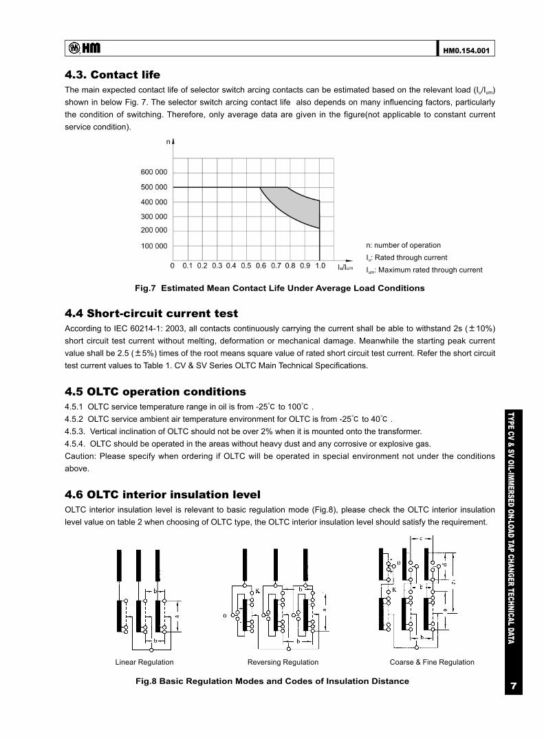
4.3. Contact life The main expected contact life of selector switch arcing contacts can be estimated based on the relevant load (Iu/Ium) shown in below Fig. 7. The selector switch arcing contact life also depends on many influencing factors, particularly the condition of switching. Therefore, only average data are given in the figure(not applicable to constant current service condition).
n: number of operation
Iu: Rated through current
Ium: Maximum rated through current
Linear Regulation Reversing Regulation Coarse & Fine Regulation
Fig.7 Estimated Mean Contact Life Under Average Load Conditions
Fig.8 Basic Regulation Modes and Codes of Insulation Distance
4.4 Short-circuit current test According to IEC 60214-1: 2003, all contacts continuously carrying the current shall be able to withstand 2s (±10%) short circuit test current without melting, deformation or mechanical damage. Meanwhile the starting peak current value shall be 2.5 (±5%) times of the root means square value of rated short circuit test current. Refer the short circuit test current values to Table 1. CV & SV Series OLTC Main Technical Specifications.
4.5 OLTC operation conditions 4.5.1 OLTC service temperature range in oil is from -25℃ to 100℃ . 4.5.2 OLTC service ambient air temperature environment for OLTC is from -25℃ to 40℃ . 4.5.3. Vertical inclination of OLTC should not be over 2% when it is mounted onto the transformer. 4.5.4. OLTC should be operated in the areas without heavy dust and any corrosive or explosive gas. Caution: Please specify when ordering if OLTC will be operated in special environment not under the conditions above.
4.6 OLTC interior insulation level OLTC interior insulation level is relevant to basic regulation mode (Fig.8), please check the OLTC interior insulation level value on table 2 when choosing of OLTC type, the OLTC interior insulation level should satisfy the requirement.

HM0.154.001
TYPE CV & SV OIL-IMMERSED ON-LOAD TAP CHANGER TECHNICAL DATA
8
Insulation distance Withstand voltage
OLTC type
CVⅢ 350Y CVⅢ 350D CVⅠ350
SVⅢ 500Y SVⅢ 500D CVⅠ700
a
10 contact pitcheskV, 1.2/50μs 200
kV, 50Hz 1min 50
12 contact pitcheskV, 1.2/50μs 180
kV, 50Hz 1min 50
14 contact pitcheskV, 1.2/50μs 170
kV, 50Hz 1min 50
b
40.5kVkV, 1.2/50μs 200 225 -
kV, 50Hz 1min 70 85 -
72.5kVkV, 1.2/50μs 200 350 -
kV, 50Hz 1min 70 140 -
c
40.5kVkV, 1.2/50μs 350 350 -
kV, 50Hz 1min 140 140 -
72.5kVkV, 1.2/50μs 350 350 -
kV, 50Hz 1min 140 140 -
dkV, 1.2/50μs 200
kV, 50Hz 1min 53
f
40.5kVkV, 1.2/50μs 225
kV, 50Hz 1min 85
72.5kVkV, 1.2/50μs 350
kV, 50Hz 1min 140
Table 2 OLTC Interior Insulation Level
Note:a: between maximum tap and minimum tap of the same phaseb: between any two taps of the different phasec: between the beginning of the coarse tap of different phased: between the beginning and the end of coarse tap of the same phasef: to ground

HM0.154.001
TYPE CV & SV OIL-IMMERSED ON-LOAD TAP CHANGER TECHNICAL DATA
9
Fig.9 The Voltage Gradient For The Coarse Regulation
Table 3 OLTC Insulation Level To Earth
The voltage gradient between the terminals of change-over selector and the upper terminals of the selector for thecoarse regulation. (refer to Fig.9)
Note: Because of the practical arrangement of the change-over selector, the voltage gradient between the terminal "0" of the change-over selector and the upper terminal of the selector corresponds to the insulation distance "a" (same phase) or the insulation distance "b" (phase to phase). The insulation distance between the fine regulation selector and the change-over selector is principally not to be considered.
4.7 OLTC insulation to earth OLTC insulation to earth, that is insulation between OLTC live parts and earth portion, its rated value determined by dielectric tests according to IEC-60214-1(2003), please refer to table 3 below.
The demand of insulation to earth for OLTC is relevant to OLTC connection location at transformer tap winding, regulation range and mode, tap winding connection model and structure disposal, as well as the rated voltage of transformer tap winding, anyhow, it is determined by insulation to ground of transformer voltage regulating winding.
The highest voltage for equipment(kV)
Rated separate source AC withstandvoltage (kV/50Hz, 1min)
Rated lightning impulse withstandvoltage (kV, 1.2/50μs)
40.5 85 225
72.5 140 350
4.8 OLTC installation method CV & SV OLTC is mounted onto transformer tank cover via head flange, thus, there is connection flange which should be prepared by transformer producer, please refer to 9.11 "Schematic diagram of transformer connection flange" for dimensions. OLTC is suitable for standard tank type or bell-type transformer, for bell-type mounting, the OLTC supporting flange is used as temporary support when connection the tap changer to transformer winding, after transformer bell-cover mounted well, the OLTC should be fixed onto transformer connection flange.
(unit: kV)

HM0.154.001
TYPE CV & SV OIL-IMMERSED ON-LOAD TAP CHANGER TECHNICAL DATA
10
5. Special design
Potential connection of the tap winding
For high voltage or wide regulation range on-load regulating transformer, during the operation of the change-over selector the tap winding is disconnected momentarily from the main winding, the regulating section will be broken away from the main coil and at status of "suspend", thus voltage regulating winding will gain the new potential that depends upon coupling capacities Ce (to ground) and Cw (between adjacent tap winding), refer to Fig.11. Generally this potential is different from the one of voltage regulating winding before change-over selector acting, the difference of them is designated as bias voltage. This bias voltage is produced at the breaking point of the separated contacts during the operation of change-over selector. If these differential voltages exceed a certain limit value, it may cause spark on change-over selector and bring a number of gas, it will be the serious problem. Therefore measures regarding potential connection of the winding must be taken.
The limiting value of the bias voltage for type CV & SV is 15kV. If it is expected that the bias voltage will be higher than this value, the regulation section should be permanently connected to a fixed potential through tie-in resistors. Please refer to attachment 9.12-1 & 9.12-2.
For calculating the change-over selector stress and dimensioning the tie-in resistors, the following details of the transformer specifications required when ordering: a) Complete transformer parameter: rated capacity, rated voltage, voltage regulating range, winding connection model, insulation level and so on b) Arrangement of the windings, i.e. the relative position of the tap winding to the adjacent coil or winding parts c) Operating a.c.voltage across windings or layers of windings adjacent to the tap windings d) Capacitance of the tap winding to adjacent windings(Cw) e) Capacitance of the tap winding to ground or grounded adjacent windings (if exist) (Ce) f) Voltage stress across half the tap winding at lightning impulse voltage test g) A.C.voltage across half the tap winding under operation and test conditions. ( is normally derived from order specification sheet for tap changer)
Fig.10 Potential Connection WithPermanently Connected Tie-In
Resistor Rp
Fig.11 The Reversing RegulationWinding Arrangement Of Two
Windings Transformer

HM0.154.001
TYPE CV & SV OIL-IMMERSED ON-LOAD TAP CHANGER TECHNICAL DATA
11
6. Motor drive unit
CV & SV OLTC may operated by SHM-III or CMA9 motor drive unit, it could be also driven by CMA7 motor drive unit according to the requirement.
SHM-III motor drive unit is developed by Huaming with many advantages, the mechanism transmission system is installed into SHM-III cabinet, and control system is integrated inside HMK8 which is mounted in control room, thus to ensure the operation reliability. Please refer to table 4 for motor drive unit technical data.
Motor drive unit SHM-III CMA7 CMA9
Motor
Rated power (W) 750 1100 750 1100 370
Rated voltage (V) 380,3AC/N 380/3AC 380/3AC
Rated current (A) 2.1 2.8 2.0 2.8 1.1
Rate frequency(Hz) 50 or 60 50 or 60 50 or 60
Rotate speed (r.p.m.) 1400 1400 1400
Rated torque on drive shaft (Nm) 45 66 18 26 40
Revolution of the drive shaft per switching operation 33 33 2
Revolution of the hand crank per switching operation 33 33 30
Running time per switching operation (S) 5.6 About 5 About 4
Max. operation positions 35 107 27
Voltage for control circuit and heater circuit (V) 220/AC 220/AC 220/AC
Heater power (W) 50 50 30
A.C. voltage test to ground (kV/50Hz, 1min) 2 2 2
Approx. weight (kg) 73 90 70
Protective degree IP66 IP56 IP56
Mechanical endurance (operations) Not less than 2,000,000 Not less than 800,000
Table 4 Motor Drive Unit Technical Data
Note: Please specify if special voltage required for motor, and control & heater circuit.
7. OLTC operation controllers
7.1 HMK8 controller HMK8 controller is the device for remote control of SHM-III motor drive unit; it realizes OLTC switching operation through SHM-III. HMK8 can display the OLTC switching operation status and tap positions.
HMK8 has BCD code position signal output (contact capacity:AC250V/5A or DC30V/5A) and remote control signal input (non potential contact), it can also communicate with host computer via RS485 interface to realize remote supervising of OLTC position.

HM0.154.001
TYPE CV & SV OIL-IMMERSED ON-LOAD TAP CHANGER TECHNICAL DATA
12
HMK8 main technical data is as below, refer to HMK8 manual for more details. Working voltage: 380V, 3AC/N Power frequency: 50Hz/60Hz Maximum operation positions: 35 Environment temperature: -10℃ to 40℃ Indoor
7.2 HMC-3C position indicator HMC-3C OLTC position indicator is a support fitting for CMA7 and CMA9 motor drive unit, it can be used to indicate the OLTC position, and has the function of "1→ N", "STOP", "N→ 1" control as well as remote control indicator lamp, its input is decimal code and output is BCD code. Please refer to HMC-3C manual for details.
7.3 Automatic voltage regulator ET-SZ6 and HMK-2A Automatic voltage regulator ET-SZ6 and HMK-2A is adopted for OLTC automatic voltage regulation, ET-SZ6 can be used for parallel operation in model of master and slave, please refer to relevant manual for details.
8 OLTC accessories
8.1 Bevel gear unit Bevel gear unit is used for connecting horizontal shaft and vertical shaft between OLTC body and motor drive unit, thus driving torque of motor drive unit can be transmitted to on-load tap changer, the overall dimensions of bevel gear unit is shown on attachment 9.13.
8.2 Protective relay Protective relay is the one of protective devices for oil-immersed on-load tap changer, when OLTC interior failure produces gas and oil surge, the protective relay contact acts, and switches on to the tripping circuit of the transformer circuit breaker, the transformer will trip at once.
Protective relay is mounted onto the connection pipe between OLTC head and conservator, make sure that protective relay marked with arrowhead side shall be connected to conservator. Huaming provides two types of protective relay which are QJ4G-25 (with 1 pair of trip contact) and QJ6-25 (with 2 pairs of trip contact), please refer to attachment 9.14 for dimensions.
8.3 Pressure relief device Pressure relief valve and pressure release cover is the security protective device for oil-immersed OLTC, when OLTC interior fails, oil in oil chamber is gasified and a number of gases produced, thus oil pressure of oil chamber is increased rapidly, OLTC oil compartment will be deformed even exploded if the pressure inside is not released in time, therefore, pressure relief device is necessary to install to avoid failures exaggeration.
Pressure relief valve is a auto-sealed valve, when over pressure, the cover is open and pressure will be released, and then it will close again. It can be reused, and the liquid loss could be controlled to minimum volume when it is acting.
Pressure release cover is the weak point on the OLTC head cover, once oil chamber pressure exceeds adjusted value, the pressure release cover will be broken, thus over-pressure is released, and OLTC oil compartment is protected.
Pressure relief valve is a device for low energy failure, and pressure release cover is the device for high energy failure, whereas most of failure of OLTC body is of high energy failure, so our standard offer is OLTC equipped wiyh pressure release cover, and pressure relief valve is only provided when customer specifies. For type CV OLTC only one of them is available for selection since the space on the CV OLTC top is limited.

HM0.154.001
TYPE CV & SV OIL-IMMERSED ON-LOAD TAP CHANGER TECHNICAL DATA
13
8.4 Online oil filter plant Online oil filter plant is application for oil circulating filtering for on-load tap changer, this device can effectively purify dissociated carbon or metal particles, and reduce the water content of transformer oil inside OLTC chamber, when OLTC is on normal operation status. With online oil filtering, OLTC will have reliable operation, less maintenance, we recommend that OLTC should be equipped with online filter when it operates frequently especially when OLTC is applied for furnace transformer and rectification transformer, also for ultra high-voltage transformer, online oil filter is necessary.
OLTC type Operation condition Filter application
Type CV & SV, universal Annual tap changing operations >15,000 Recommend
CVIII-350DSVIII-500D
Operation in tropical and subtropical districts withvariation of temperature
Recommend
CVIII-350D/72.5SVIII-500D/72.5
The voltage regulating section is arranged at the startingend of the winding
Compulsory
OLTC type Water content Insulation
CVIII 350Y SVIII 500Y < 40PPm > 30kV/2.5mm
CVIII 350D SVIII 500D < 30PPm > 40kV/2.5mm
CVI 350 CVI 700 < 30PPm > 40kV/2.5mm
Table 6 Insulation And Water Content Request Of OLTC Oil
9. Appendix
HM0.154.001
TYPE CV & SV OIL-IMMERSED ON-LOAD TAP CHANGER TECHNICAL DATA
14
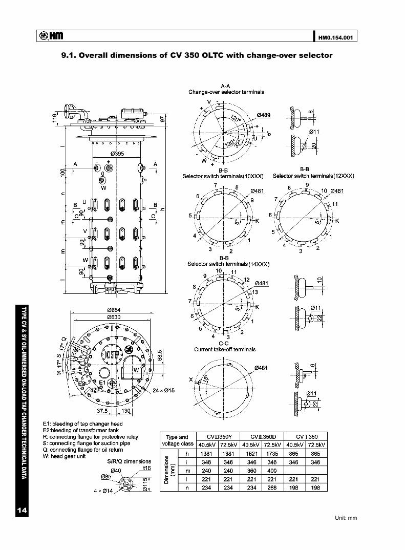
9.1. Overall dimensions of CV 350 OLTC with change-over selector
Unit: mm

HM0.154.001
TYPE CV & SV OIL-IMMERSED ON-LOAD TAP CHANGER TECHNICAL DATA
15
9.2. Overall dimensions of CV 350 OLTC without change-over selector
Unit: mm

HM0.154.001
TYPE CV & SV OIL-IMMERSED ON-LOAD TAP CHANGER TECHNICAL DATA
16
9.3. Overall dimensions of CVIII 350 OLTC bridging connection
Unit: mm

HM0.154.001
TYPE CV & SV OIL-IMMERSED ON-LOAD TAP CHANGER TECHNICAL DATA
17
9.4. Overall dimensions of SVIII 500 OLTC with change-over selector
Unit: mm
HM0.154.001
TYPE CV & SV OIL-IMMERSED ON-LOAD TAP CHANGER TECHNICAL DATA
18
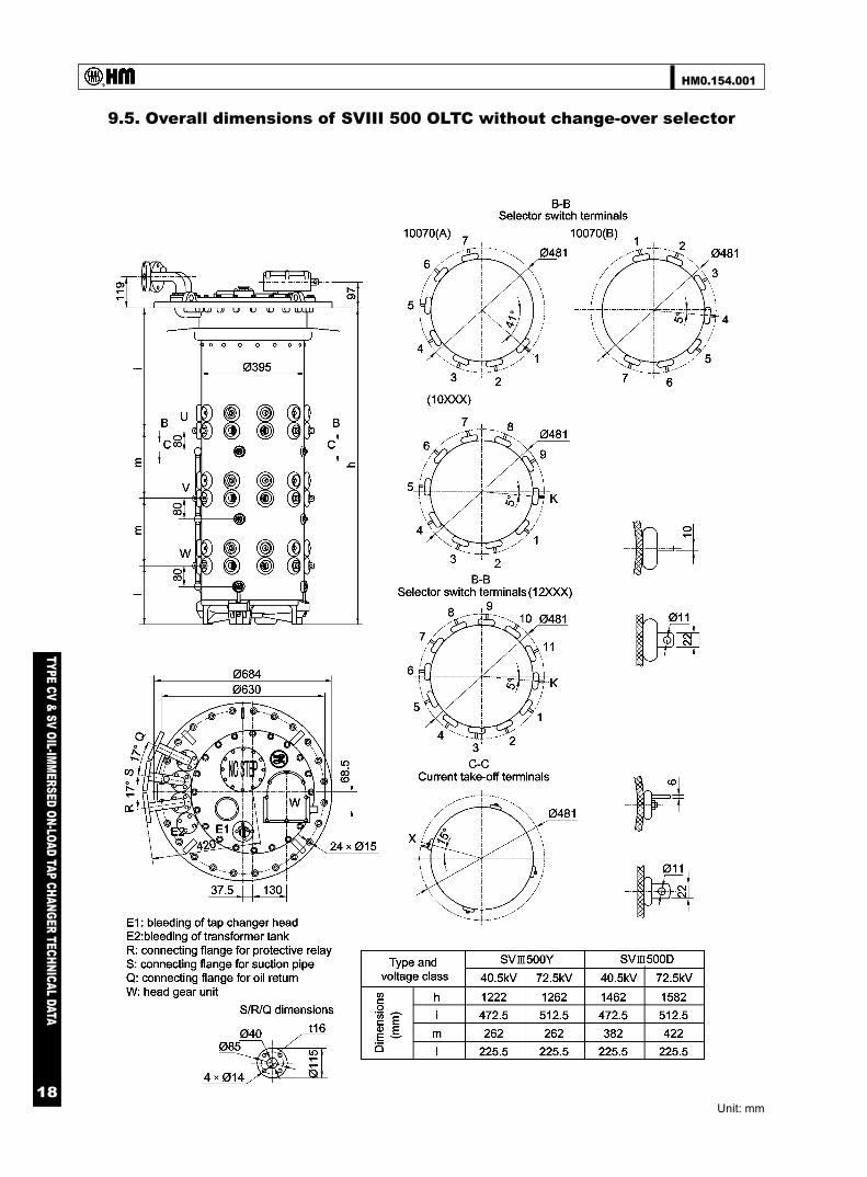
9.5. Overall dimensions of SVIII 500 OLTC without change-over selector
Unit: mm

HM0.154.001
TYPE CV & SV OIL-IMMERSED ON-LOAD TAP CHANGER TECHNICAL DATA
19
9.6. Overall dimensions of CVI 700 OLTC with change-over selector
Unit: mm

HM0.154.001
TYPE CV & SV OIL-IMMERSED ON-LOAD TAP CHANGER TECHNICAL DATA
20
9.7. Overall dimensions of CVI 700 OLTC without change-over selector
Unit: mm

HM0.154.001
TYPE CV & SV OIL-IMMERSED ON-LOAD TAP CHANGER TECHNICAL DATA
21
9.8. Overall dimensions of OLTC head flange installation for standard tank
Unit: mm

HM0.154.001
TYPE CV & SV OIL-IMMERSED ON-LOAD TAP CHANGER TECHNICAL DATA
22
9.9. Overall dimensions of OLTC head flange installation for bell-type
Unit: mm

HM0.154.001
TYPE CV & SV OIL-IMMERSED ON-LOAD TAP CHANGER TECHNICAL DATA
23
9.10. Schematic diagram of OLTC head installed with pressure relief valve
Unit: mm

HM0.154.001
TYPE CV & SV OIL-IMMERSED ON-LOAD TAP CHANGER TECHNICAL DATA
24
9.11. Schematic diagram of transformer connection flange
Unit: mm

HM0.154.001
TYPE CV & SV OIL-IMMERSED ON-LOAD TAP CHANGER TECHNICAL DATA
25
9.12 -1. Installation dimensions of tie-in resistor with 2-piece in circuit
Unit: mm

HM0.154.001
TYPE CV & SV OIL-IMMERSED ON-LOAD TAP CHANGER TECHNICAL DATA
26
9.12-2. Installation dimensions of tie-in resistor with 3-piece at bottom
Unit: mm

HM0.154.001
TYPE CV & SV OIL-IMMERSED ON-LOAD TAP CHANGER TECHNICAL DATA
27
9.13. Overall dimensions of bevel gear unit
Unit: mm

HM0.154.001
TYPE CV & SV OIL-IMMERSED ON-LOAD TAP CHANGER TECHNICAL DATA
28
9.14
. Dim
ensi
ons
of p
rote
ctiv
e re
lay
Type
QJ6
-25
prot
ectiv
e re
lay
Uni
t: m
m
Type
QJ4
G-2
5 pr
otec
tive
rela
y

HM0.154.001
TYPE CV & SV OIL-IMMERSED ON-LOAD TAP CHANGER TECHNICAL DATA
29
9.15. Operating key for OLTC insert
Unit: mm
HM0.154.001
TYPE CV & SV OIL-IMMERSED ON-LOAD TAP CHANGER TECHNICAL DATA
30
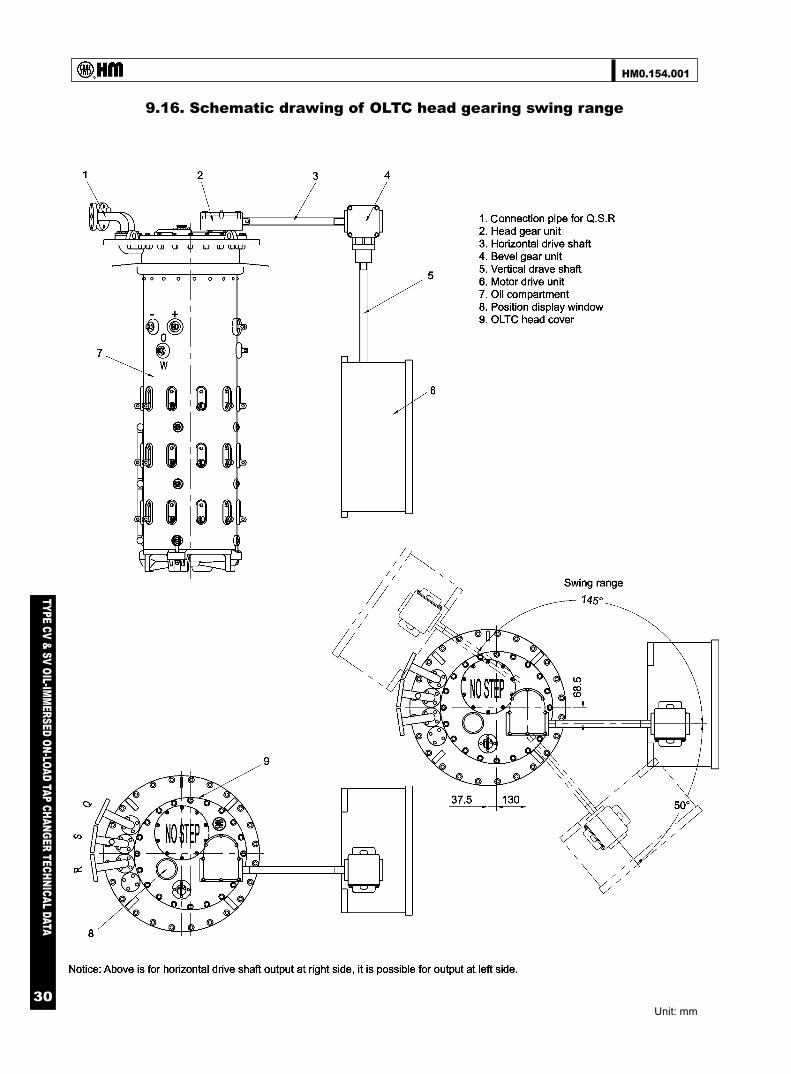
9.16. Schematic drawing of OLTC head gearing swing range
Unit: mm

HM0.154.001
TYPE CV & SV OIL-IMMERSED ON-LOAD TAP CHANGER TECHNICAL DATA
31
9.17. Schematic drawing of OLTC head gearing swing range(with pressure relief valve)
Unit: mm

HM0.154.001
TYPE CV & SV OIL-IMMERSED ON-LOAD TAP CHANGER TECHNICAL DATA
32
9.18. Schematic drawing of 3 units of single phase OLTC arrangement
Unit: mm

69
TYPE VCM O
IL-IMM
ERSED ON
-LOAD TAP CH
ANG
ER TECHN
ICAL DATA
HM0.154.5701
Printing: FEB.2010
SHANGHAI HUAMING POWER EQUIPMENT CO., LTD.
Address: 977 Tong Pu Road, Shanghai, P.R.China 200333Tel: +86 21 5270 3965(direct)
+86 21 5270 8966 Ext.8688/8123/8698/8158/8110/8658
Fax: +86 21 5270 2715Web:www.huaming.com
E-mail: [email protected]