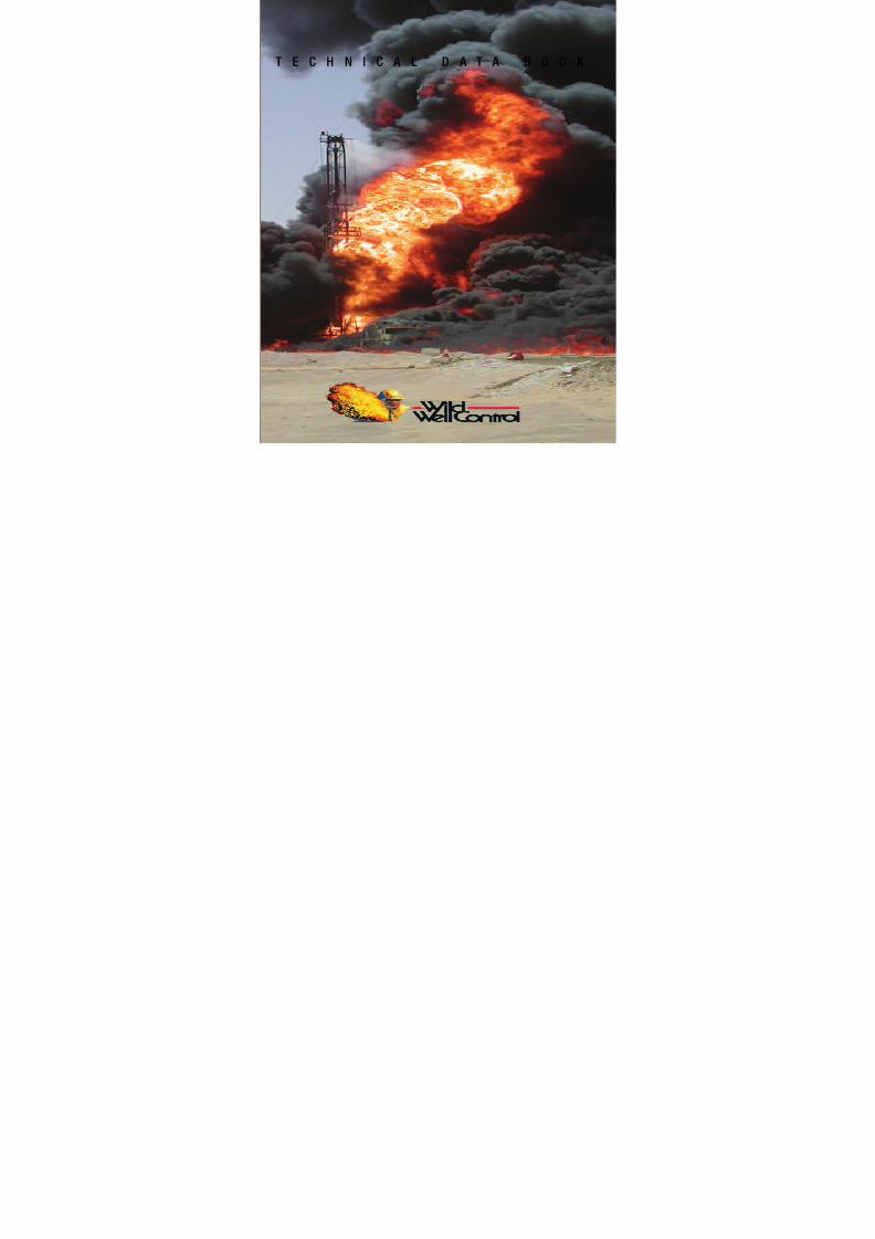
technical data book - well control 2004
TRANSCRIPT
8/15/2019 Technical Data Book - Well Control 2004
http://slidepdf.com/reader/full/technical-data-book-well-control-2004 1/66
T E C H N I C A L D A T A B O O K

8/15/2019 Technical Data Book - Well Control 2004
http://slidepdf.com/reader/full/technical-data-book-well-control-2004 2/66
Technical
Data Book
A Quic k Re fe re nc e
Book o f Fo rm ula s,
Charts a nd Ta b le s
A SUPERIOR ENERGY SERVICES COMPANY
©2004 Wild Well Control, Inc.
The information contained herein has been collectedfrom various sources. Accordingly, Wild Well Control,Inc. cannot and does not guarantee, warrant or representthe accuracy of or accept any responsibility for the useof any information contained herein.
8/15/2019 Technical Data Book - Well Control 2004
http://slidepdf.com/reader/full/technical-data-book-well-control-2004 3/66
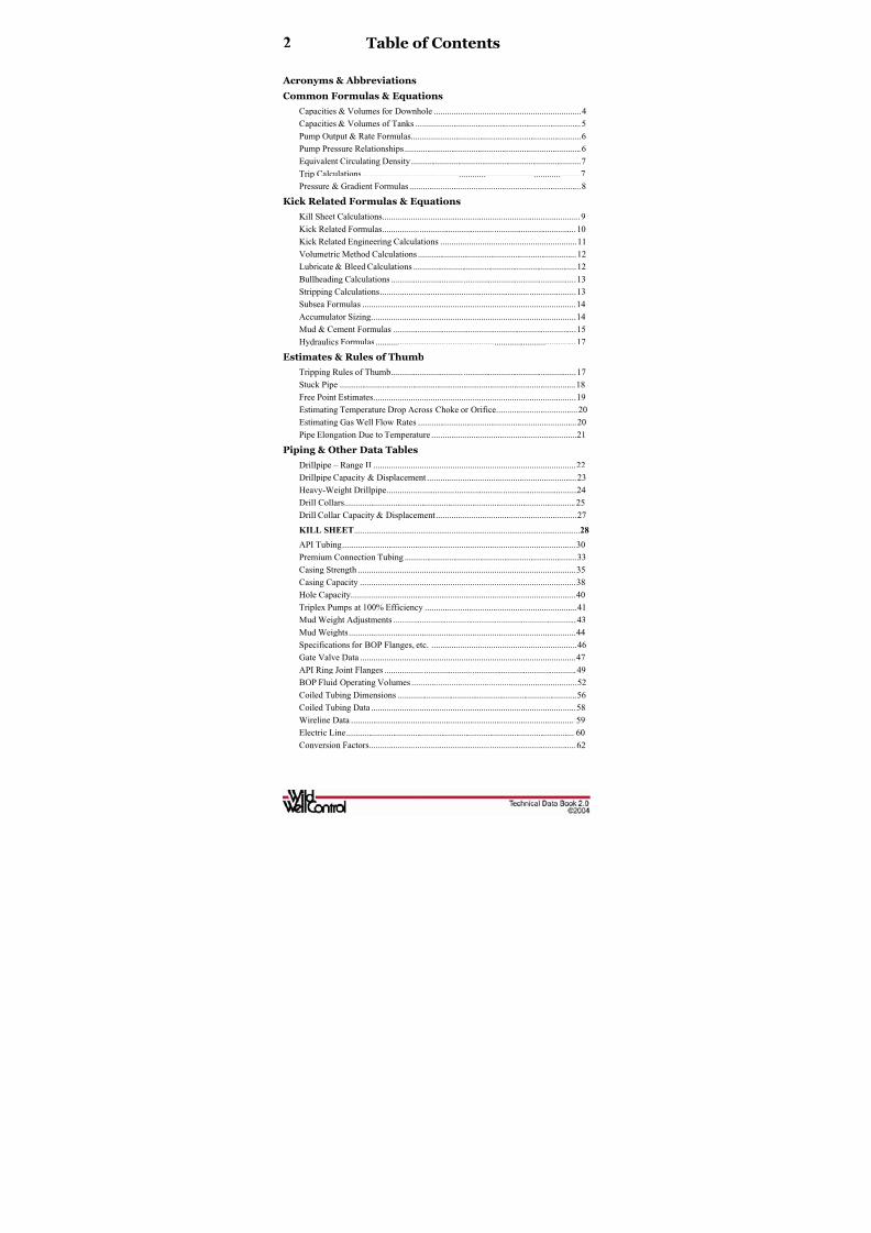
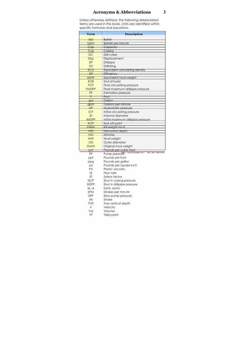
2 Table of Contents
Acronyms & Abbreviations
Common Formulas & Equations
Capacities & Volumes for Downhole ...................................................................4
Capacities & Volumes of Tanks ...........................................................................5
Pump Output & Rate Formulas.............................................................................6
Pump Pressure Relationships ................................................................................6
Equivalent Circulating Density .............................................................................7
Trip Calculations...................................................................................................7Pressure & Gradient Formulas ..............................................................................8
Kick Related Formulas & Equations
Kill Sheet Calculations..........................................................................................9
Kick Related Formulas........................................................................................10
Kick Related Engineering Calculations ..............................................................11
Volumetric Method Calculations ........................................................................12
Lubricate & Bleed Calculations ..........................................................................12
Bullheading Calculations ....................................................................................13
Stripping Calculations.........................................................................................13
Subsea Formulas .................................................................................................14
Accumulator Sizing.............................................................................................14
Mud & Cement Formulas ...................................................................................15
Hydraulics Formulas ...........................................................................................17
Estimates & Rules of Thumb
Tripping Rules of Thumb....................................................................................17
Stuck Pipe ...........................................................................................................18
Free Point Estimates............................................................................................19
Estimating Temperature Drop Across Choke or Orifice.....................................20
Estimating Gas Well Flow Rates ........................................................................20
Pipe Elongation Due to Temperature ..................................................................21
Piping & Other Data Tables
Drillpipe – Range II ............................................................................................22
Drillpipe Capacity & Displacement ....................................................................23
Heavy-Weight Drillpipe......................................................................................24
Drill Collars.........................................................................................................25
Drill Collar Capacity & Displacement................................................................27
KILL SHEET............................................................................................................. 28
API Tubing..........................................................................................................30
Premium Connection Tubing ..............................................................................33
Casing Strength ...................................................................................................35
Casing Capacity ..................................................................................................38
Hole Capacity......................................................................................................40
Triplex Pumps at 100% Efficiency .....................................................................41
Mud Weight Adjustments ...................................................................................43Mud Weights.......................................................................................................44
Specifications for BOP Flanges, etc. ..................................................................46
Gate Valve Data ..................................................................................................47
API Ring Joint Flanges .......................................................................................49
BOP Fluid Operating Volumes ...........................................................................52
Coiled Tubing Dimensions .................................................................................56
Coiled Tubing Data .............................................................................................58Wireline Data ......................................................................................................59
Electric Line........................................................................................................60
Conversion Factors..............................................................................................62
8/15/2019 Technical Data Book - Well Control 2004
http://slidepdf.com/reader/full/technical-data-book-well-control-2004 4/66
8/15/2019 Technical Data Book - Well Control 2004
http://slidepdf.com/reader/full/technical-data-book-well-control-2004 5/66
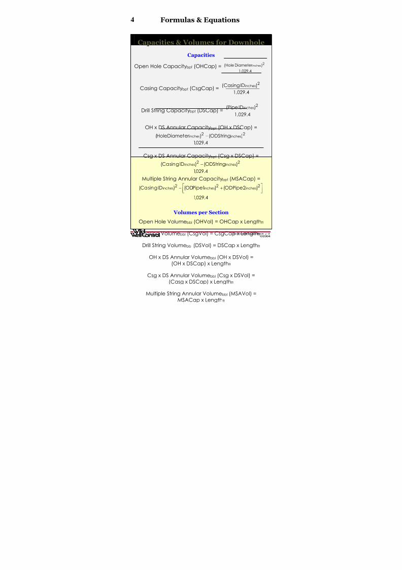
4 Formulas & Equations
CCaappaacciittiieess && V V oolluummeess f f oorr DDoo w w nnhhoollee
Capacities
Open Hole Capacitybpf (OHCap) =1,029.4
)Diameter (Hole 2inches
Casing Capacitybpf (CsgCap) =1,029.4
)ID(Casing 2inches
Drill String Capacitybpf (DSCap) =1,029.4
)ID(Pipe 2inches
OH x DS Annular Capacitybpf (OH x DSCap) =
4.029,1
)ODString()er HoleDiamet( 22inchesinches −
Csg x DS Annular Capacitybpf (Csg x DSCap) =
4.029,1)ODString()IDgsinCa( 22 inchesinches −
Multiple String Annular Capacitybpf (MSACap) =
4.029,1
)2ODPipe()1PipeOD()IDgsinCa( 222inchesinchesinches
⎥⎦⎤
⎢⎣⎡ +−
Volumes per Section
Open Hole Volumebbl (OHVol) = OHCap x Lengthft
Casing Volumebbl (CsgVol) = CsgCap x Lengthft
Drill String Volumebbl (DSVol) = DSCap x Lengthft
OH x DS Annular Volumebbl (OH x DSVol) =
(OH x DSCap) x Lengthft
Csg x DS Annular Volumebbl (Csg x DSVol) =
(Casg x DSCap) x Lengthft
Multiple String Annular Volumebbl (MSAVol) =
MSACap x Lengthft

8/15/2019 Technical Data Book - Well Control 2004
http://slidepdf.com/reader/full/technical-data-book-well-control-2004 6/66
Formulas & Equations 5
CCaappaacciittiieess && V V oolluummeess oof f TTaannk k ss
Vertical Cylindrical Tanks
Capacitybbl/ft =( )
7.148
Diameter Tank 2
ft
Capacitybbl/ft = ( )1,029.4
Diameter Tank 2inches
Capacitybbl/inch =( )
85.78
Diameter Tank 2
ft
Capacitybbl/inch = ( )12,352.9Diameter Tank
2inches
Volumebbl = Capacitybbl/ft x Heightft
Volumebbl = Capacitybbl/inch x Heightinches
Rectangular Tanks
Capacitybbl/ft = 0.178 x Lengthft x Widthft
Capacitybbl/inch = 0.0148 x Lengthft x Widthft
Volumebbl = Capacitybbl/ft x Heightft
Volumebbl = Capacitybbl/inch x Heightinches
Horizontal Cylindrical Tanks
Volume of Tank bbl =( )
1,029.4
Diameter Tank Length
2inches
ft ×
Content from Volume (for Horizontal Tanks)
Height Ratio =inches
inches
Tank ofHeight
ContentofHeight
FIND VOLUME FACTOR FROM TABLE USING CALCULATED HEIGHT
RATIO:
Content in Tank bbl = Vol of Tank bbl x Volume Factor
HeightRatio
VolumeFactor
HeightRatio
VolumeFactor
0.05 0.019 0.55 0.560
0.10 0.052 0.60 0.626
0.15 0.092 0.65 0.690
0.20 0.142 0.70 0.747
0.25 0.195 0.75 0.800
0.30 0.252 0.80 0.8570.35 0.310 0.85 0.900
0.40 0.373 0.90 0.948
0.45 0.430 0.95 0.980
0.50 0.500 1.00 1.000
8/15/2019 Technical Data Book - Well Control 2004
http://slidepdf.com/reader/full/technical-data-book-well-control-2004 7/66
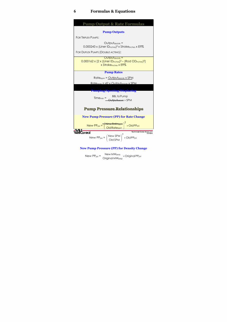
6 Formulas & Equations
PPuummpp OOuuttppuutt && R R aattee FFoorrmmuullaass
Pump Outputs
FOR TRIPLEX PUMPS:
Outputbbl/stk =
0.000243 x (Liner IDinches)2 x Strokeinches x Eff%
FOR DUPLEX PUMPS (DOUBLE ACTING):
Outputbbl/stk =
0.000162 x [2 x (Liner IDinches)2 – (Rod ODinches)2]
x Strokeinches x Eff%
Pump Rates
Ratebpm = Outputbbl/stk x SPM
Rategpm = 42 x Outputbbl/stk x SPM
Pumping/Spotting/Displacing
Timemin =SPMOutput
PumptoBBL
bbl/stk ×
PPuummpp PPrreessssuurree R R eellaattiioonnsshhiippss
New Pump Pressure (PP) for Rate Change
New PPpsi = psibpm
bpmPPOld
RateOld
RateNew2
×⎟⎟ ⎠
⎞⎜⎜⎝
⎛
New PPpsi = psiPPOldSPMOld
SPMNew2
×⎟⎟ ⎠
⎞
⎜⎜⎝
⎛
New Pump Pressure (PP) for Density Change
New PPpsi = psippg
ppgPPOriginal
MWOriginal
MWNew×

8/15/2019 Technical Data Book - Well Control 2004
http://slidepdf.com/reader/full/technical-data-book-well-control-2004 8/66
Formulas & Equations 7
EEq q uuii v v aalleenntt CCiirrccuullaattiinngg DDeennssiitt y y ((EECCDD))
Equivalent Circulating Density(ECDppg) using Pressure Loss
ECDppg =ft
psippg
TVD052.0
LossPressureFrictionAnnular MW
×+
Where:
Annular Friction Pressure Loss in psi is approximately
equal to 10% of the pump pressure for normal hole
geometries (i.e., no liners or tapered strings).
Equivalent Circulating Density (ECDppg)
using Yield Point (YP) for MW 13 ppg
ECDppg =inchesinches PipeOD-HoleOD
YP1.0MWppg
×+
Where:
YP = Fann 300 reading – PV
PV = Fann 600 reading – Fann 300 reading
Equivalent Circulating Density (ECDppg)using Yield Point (YP) for MW > 13 ppg
ECDppg =inchesinches
ppgPipeODHoleOD
1.0MW
−+
( ) ⎟⎟ ⎠
⎞⎜⎜⎝
⎛
−× ×+×inchesinches
min/ft
PipeODHoleOD300VPVYP
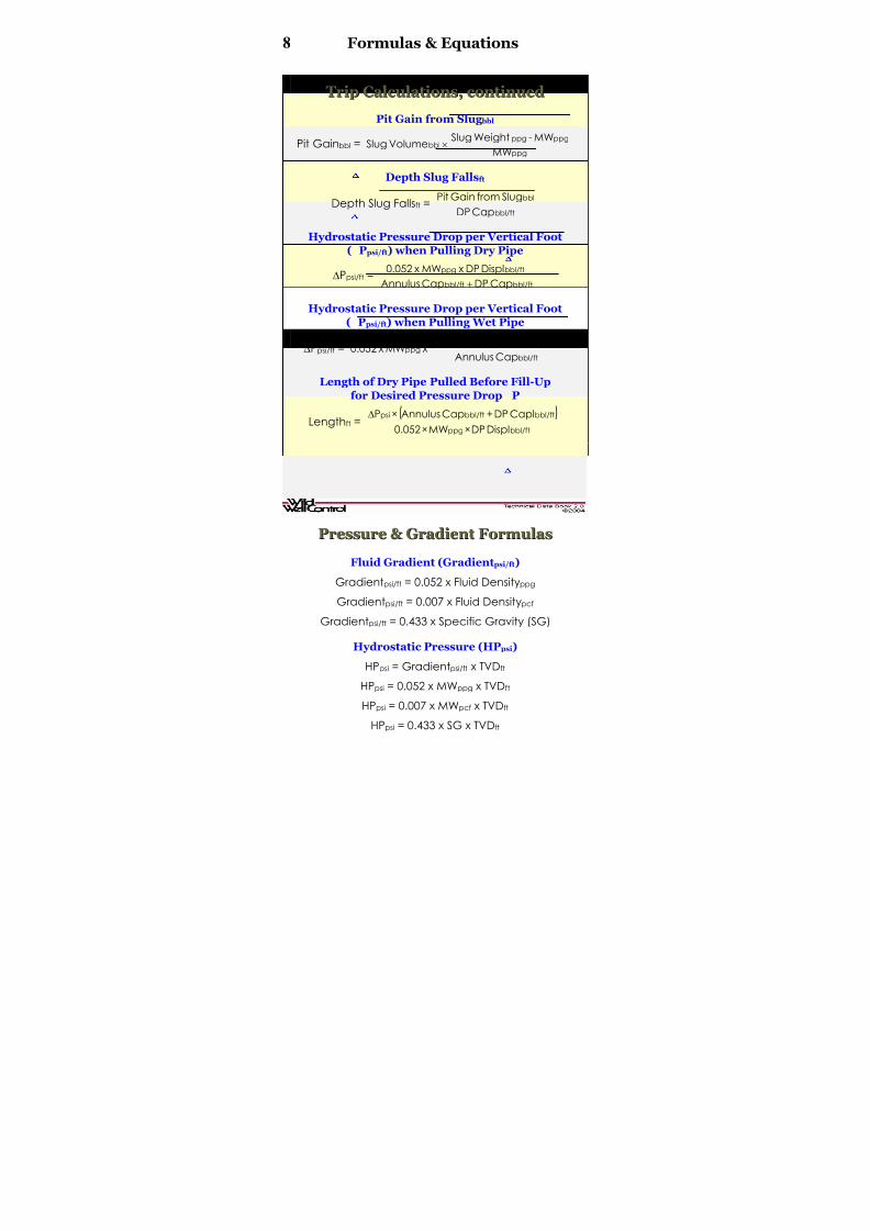
TTrriipp CCaallccuullaattiioonnss
Trip Marginppg
Trip Marginppg =( )inchesinches
mud
ODPipe-Diameter Hole11.7YP
×
Trip Marginppg =ft
psi
TVD052.0
LossPressureAnnular
×
Slug Mud Weightppg for a given Length of Dry Pipe
Slug Weightppg =
( )bbl
bbl/ftftppgppg
SlugofVolume
CapDPPipeDryLengthMW MW
××+
Slug Volume bbl for a given Length of Dry Pipe
Slug Volumebbl = ppgbbl
bbl/ftftppg
MW-MWSlug
CapDPPipeDryLengthMW ××
8/15/2019 Technical Data Book - Well Control 2004
http://slidepdf.com/reader/full/technical-data-book-well-control-2004 9/66
8 Formulas & Equations
TTrriipp CCaallccuullaattiioonnss,, ccoonnttiinnuueedd
Pit Gain from Slug bbl
Pit Gainbbl =ppg
ppgppgbbl
MW
MW-WeightSlugVolumeSlug ×
Depth Slug Fallsft
Depth Slug Fallsft =bbl/ft
bbl
CapDP
SlugfromGainPit
Hydrostatic Pressure Drop per Vertical Foot
( Ppsi/ft) when Pulling Dry Pipe
∆Ppsi/ft =bbl/ftbbl/ft
bbl/ftppg
CapDPCapAnnulus
DisplDP xMW x0.052
+
Hydrostatic Pressure Drop per Vertical Foot
( Ppsi/ft) when Pulling Wet Pipe
∆Ppsi/ft =
( )bbl/ft
bbl/ftbbl/ft
ppg CapAnnulus
DisplDPCapDP
xMW x0.052
+
Length of Dry Pipe Pulled Before Fill-Up
for Desired Pressure Drop P
Lengthft =( )
bbl/ftppg
bbl/ftbbl/ftpsi
DisplDP×MW×0.052
CaplDP+CapAnnulus×P∆
Length of Wet Pipe Pulled Before Fill-Up
for Desired Pressure Drop P
Lengthft = ( )bbl/ftbbl/ftppg
bbl/ftpsi
DisplDP+CapDP×MW×0.052
CapAnnulus×P∆
PPrreessssuurree && GGrraaddiieenntt FFoorrmmuullaass
Fluid Gradient (Gradientpsi/ft)
Gradientpsi/ft = 0.052 x Fluid Densityppg
Gradientpsi/ft = 0.007 x Fluid Densitypcf
Gradientpsi/ft = 0.433 x Specific Gravity (SG)
Hydrostatic Pressure (HPpsi)
HPpsi = Gradientpsi/ft x TVDft
HPpsi = 0.052 x MWppg x TVDft
HPpsi = 0.007 x MWpcf x TVDft
HPpsi = 0.433 x SG x TVDft
8/15/2019 Technical Data Book - Well Control 2004
http://slidepdf.com/reader/full/technical-data-book-well-control-2004 10/66
Formulas & Equations 9
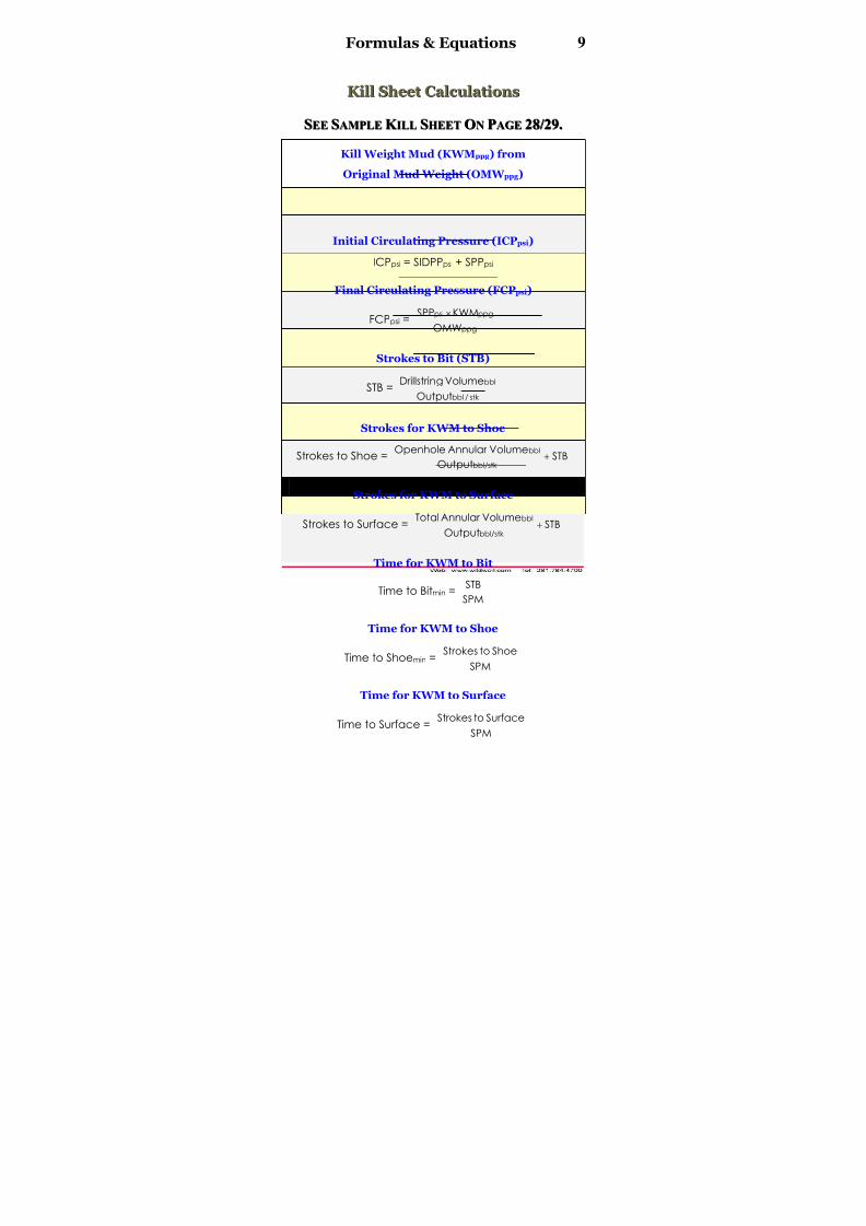
K K iillll SShheeeett CCaallccuullaattiioonnss
SSEEEE SSAAMMPPLLEE K K IILLLL SSHHEEEETT OONN PPAAGGEE 2288//2299..
Kill Weight Mud (KWMppg) from
Original Mud Weight (OMW ppg)
KWMppg =( )
ppgft
psiOMW
TVD052.0
SIDPP+
×
Initial Circulating Pressure (ICPpsi)
ICPpsi = SIDPPpsi + SPPpsi
Final Circulating Pressure (FCPpsi)
FCPpsi =ppg
ppgpsi
OMW
KWMSPP ×
Strokes to Bit (STB)
STB =stk /bbl
bbl
Output
VolumegDrillstrin
Strokes for KWM to Shoe
Strokes to Shoe = STBOutput
VolumeAnnular Openhole
bbl/stk
bbl+
Strokes for KWM to Surface
Strokes to Surface = STBOutput
VolumeAnnular Total
bbl/stk
bbl
+
Time for KWM to Bit
Time to Bitmin =SPM
STB
Time for KWM to Shoe
Time to Shoemin =SPM
ShoetoStrokes
Time for KWM to Surface
Time to Surface =SPM
SurfacetoStrokes

8/15/2019 Technical Data Book - Well Control 2004
http://slidepdf.com/reader/full/technical-data-book-well-control-2004 11/66
10 Formulas & Equations
K K iicck k R R eellaatteedd FFoorrmmuullaass
Length of Influx
Influx Lengthft =bbl/ft
bbl
CapAnnulusLower
SizeInflux
Expected Pit Gain (MPG bbl) with aGas Kick in Water-Based Mud Systems
MPGbbl =ppg
ft/bblbblpsi
KWM
CapAnnular GainOriginalFP4
×××
Expected Surface Pressure (MSPpsi) from aGas Kick in Water-Based Mud Systems
MSPpsi =bbl/ft
ppgbblpsi
CapAnnular Surface
KWM×GainOriginal×FP×20.0
Maximum Allowable Mud Weight (MAMW ppg)
MAMWppg = ppg
shoe
MWTest
TVD052.0
PressureApplied+
×
No te : Ap p lie d Pre ssure from Inte g rity o r Le a k-O ff te st.
Maximum Allowable Shut-InCasing Pressure (MASPpsi)
MASPpsi = 0.052 x (MAMWppg – MWppg) x TVDshoe
Kick Tolerance (KTppg) with Influx
KTppg = ( ) ⎥⎦
⎤⎢⎣
⎡×−
ft
shoeppgppg
TVD
TVDMWMAMW
– ( ) ⎥⎦
⎤⎢⎣
⎡×−
ft
VDftppgppg
TVD
HeightInfluxMWIMW
Where:MWIppg = Density of influx (ppg)
Estimated Kick Density
Kick Densityppg =TVDft
psipsippg
LengthKick 052.0
SIDPPSICPMW
×−
−
Kick Gradientpsi/ft
Kick Gradientpsi/ft = ( )TVDft
psipsippg
LengthKick
SIDPPSICP052.0MW
−−×
Gas Migration Distance
DistanceTVDft =052.0MW
SICPinRise
ppg
psi
×
Rate of Gas Migration
Migration RateTVDft/min =min
TVDft
Risefor Time
RiseofDistance
8/15/2019 Technical Data Book - Well Control 2004
http://slidepdf.com/reader/full/technical-data-book-well-control-2004 12/66
Formulas & Equations 11
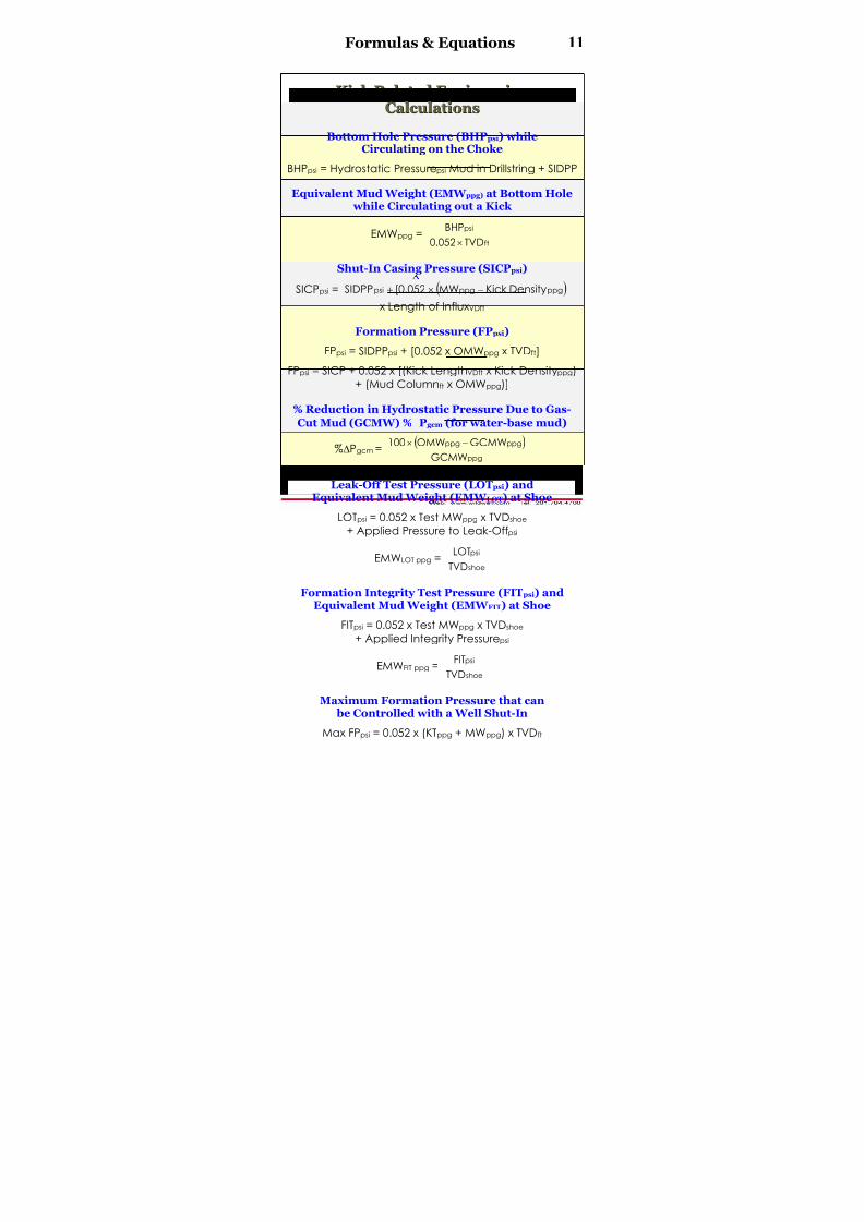
K K iicck k R R eellaatteedd EEnnggiinneeeerriinngg
CCaallccuullaattiioonnss
Bottom Hole Pressure (BHPpsi) whileCirculating on the Choke
BHPpsi = Hydrostatic Pressurepsi Mud in Drillstring + SIDPP
Equivalent Mud Weight (EMW ppg) at Bottom Hole while Circulating out a Kick
EMWppg =ft
psi
TVD052.0
BHP
×
Shut-In Casing Pressure (SICPpsi)
SICPpsi = ( )ppgppgpsi DensityKick MW052.0[SIDPP −×+
x Length of InfluxVDft
Formation Pressure (FPpsi)
FPpsi = SIDPPpsi + [0.052 x OMWppg x TVDft]
FPpsi = SICP + 0.052 x [(Kick LengthVDft x Kick Densityppg)
+ (Mud Columnft x OMWppg)]
% Reduction in Hydrostatic Pressure Due to Gas-
Cut Mud (GCMW) % Pgcm (for water-base mud)
%∆Pgcm = ( )ppg
ppgppg
GCMW
GCMWOMW100 −×
Leak-Off Test Pressure (LOTpsi) andEquivalent Mud Weight (EMW LOT) at Shoe
LOTpsi = 0.052 x Test MWppg x TVDshoe
+ Applied Pressure to Leak-Offpsi
EMWLOT ppg =shoe
psi
TVD
LOT
Formation Integrity Test Pressure (FITpsi) andEquivalent Mud Weight (EMW FIT) at Shoe
FITpsi = 0.052 x Test MWppg x TVDshoe
+ Applied Integrity Pressurepsi
EMWFIT ppg =shoe
psi
TVD
FIT
Maximum Formation Pressure that can be Controlled with a Well Shut-In
Max FPpsi = 0.052 x (KTppg + MWppg) x TVDft
8/15/2019 Technical Data Book - Well Control 2004
http://slidepdf.com/reader/full/technical-data-book-well-control-2004 13/66
8/15/2019 Technical Data Book - Well Control 2004
http://slidepdf.com/reader/full/technical-data-book-well-control-2004 14/66
Formulas & Equations 13
BBuullllhheeaaddiinngg CCaallccuullaattiioonnss
Kill Weight Mud (KMppg)
KWMppg =TVDft
psi
DepthPerfs052.0
PressureFormation
×
Formation Integrity Pressure(FITpsi) at Perfs Depth
FITpsi = 0.052 x (EMWFIT ppg at perf) x Perfs TVDft
Hydrostatic Pressure (HPpsi) in Drillpipe
HPpsi = Formation Pressurepsi – SIDPPpsi
Initial Maximum Drillpipe Pressure (IMDPPpsi)
IMDPPpsi = FITpsi – HPpsi
Hydrostatic Pressure from KWMppg (KMHPpsi)
KMHPpsi = 0.052 x KWMppg x Perfs TVDft
Final Maximum Drillpipe Pressure (FMDPPpsi)
FMDPPpsi = FITpsi – KMHPpsi
SSttrriippppiinngg CCaallccuullaattiioonnss
Minimum Surface Pressure that will Allow Stripping In Pstrip (psi)
Pstrip =2
dc
ftppf
OD0.785
StandDCLength xDCWeight
×
Influx Height Gain from Stripping Into
∆Heightft =( )
bpf
bpfbpfstrip
CapAnnulus
DPDisplDPCap xLengthPipe +
Casing Pressure Increase ( SICP)from Stripping into an Influx
∆SICPpsi = ∆Heightft x (Gradientmud – Gradientinflux)
Mud Volume to Bleed to MaintainConstant Bottom Hole Pressure
BleedMudbbl =
psi/ft
bbl/ftpsi
GradientMud
CapAnnulus xIncrementPressureCsg
8/15/2019 Technical Data Book - Well Control 2004
http://slidepdf.com/reader/full/technical-data-book-well-control-2004 15/66

8/15/2019 Technical Data Book - Well Control 2004
http://slidepdf.com/reader/full/technical-data-book-well-control-2004 16/66
Formulas & Equations 15
A A ccccuummuullaattoorr SSiizziinngg,, ccoonnttiinnuueedd
Accumulator Volume Required
Usable hydraulic fluid for operation of blowout
preventer equipment is affected by system pressure
and nitrogen precharge. If the nitrogen precharge is
at the correct (recommended) precharge, multiply
the sizing factor from the table below times the fluid
volume required to operate a specified number of
BOP functions (Volreq) will provide the required total
accumulator volume.
AccumulatorSystemPressure
Minimum
RecommendedPrechargePressure
UseableFluid
AccumulatorSize Factor*
1,500 750 12.5% 8
2,000 1,000 33.0% 3
3,000 1,000 50.0% 2
5,000 1,000 63.0% 1.6
* Ba sed o n m inim um system p re ssure o f 1,200 p si.
Accumulator Volume Example
If the total fluid required for a BOP stack is 33 gallons,
including the safety factor, and the accumulator has
an operating pressure of 3,000 psi with a 1,000 psiminimum precharge, the accumulator volume
required is 33 gallons times the size factor of 2, or
66 gallons.
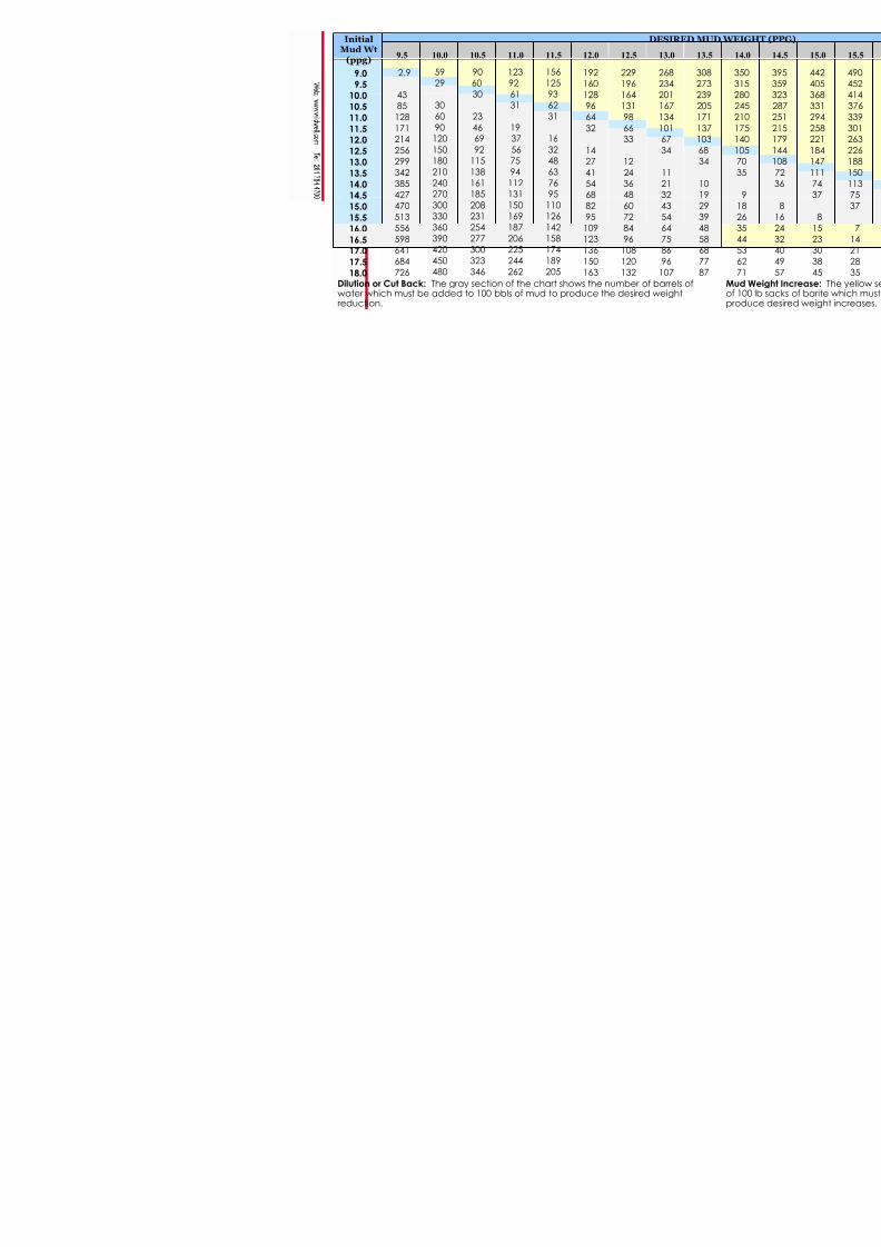
MMuudd && CCeemmeenntt FFoorrmmuullaass
Barite (100 lb sx) Per 100 bblRequired for Weight-Up
Sacks per 100 bbl =ppg
ppgppg
KWM-35
OMW-KWM1,470×
Hematite (100 lb sx) Per 100 bblRequired for Weight-Up
Sacks per 100 bbl =ppg
ppgppg
KWM-35
OMW-KWM1,680×
Pit Volume Increase per 100 bbl ( V 100bbl)
due to Weight-Up with Barite
∆V100bbl =ppg
ppgppg
KWM-35
OMW-KWM100×
8/15/2019 Technical Data Book - Well Control 2004
http://slidepdf.com/reader/full/technical-data-book-well-control-2004 17/66
16 Formulas & Equations
MMuudd && CCeemmeenntt FFoorrmmuullaass,, ccoonnttiinnuueedd
Final Mud Weight (MW ppg) whenMixing Two Densities of Mud
MWppg =( ) ( )
bbl+bbl
ppgbblppgbbl
Vol2Vol1
MW2×Vol2+MW1×Vol1
Initial Mud Volume Required (IVol bbl) to Builda Final Volume of Mud with Barite
IVolbbl =ppg
ppgbbl
OMW-35
KWM-35 VolFinal ×
Sacks of (94 lb) Cement Required
Sacks94lb =cf/sk
ftbbl/ftcf/bbl
Yield
%Excess xLength xCap x5.615
Mix Fluid Requirement
Mix Fluidbbl = ( )gal/bbl
gal/sk
42
ReqFluidMixMixtoSacksNo. ×
Balanced Plug (Cement, Barite, etc.)
a) CALCULATE VOLUME OF PLUG (PLUGVOLBBL):
PlugVolbbl = LengthPlug ft x Hole Capbbl/ft
b) CALCULATE LENGTH OF BALANCED COLUMN
(LENGTHCOL FT):
LENGTHCOL FT =bbl/ftbbl/ft
bbl
CapDPCapAnnulus
PlugVol
+
c) CALCULATE TOTAL STRING VOLUME TO BALANCE:
VolBalancebbl =
= (Plug Bottom Depthft – LENGTHCOL FT) x DPCapbbl/ft
d) CALCULATE RATIO OF SPACER INSIDE AND OUTSIDE
OF STRING:
Ratiospacer =bbl/ft
bbl/ft
CapDP
CapAnnular
e) CALCULATE DISPLACEMENT VOLUME (DISPLVOLBBL):
DisplVolbbl = VolBalancebbl – Spacer Behindbbl

8/15/2019 Technical Data Book - Well Control 2004
http://slidepdf.com/reader/full/technical-data-book-well-control-2004 18/66
Formulas & Equations 17
HH y y ddrraauulliiccss FFoorrmmuullaass
Annular Velocity (AV ft/min)
Vft/min =22 PipeOD-HoleOD
Pump Rate51.24 gpm×
Hydraulic Horsepower (HHP)
HHP =1,714
PressurePump xQ psigpm
HHP =
40.8
PressurePump xQ psibpm
Rules of Thumb
TTrriippppiinngg R R uulleess oof f TThhuumm b b
Ideally, drillers would like to keep bottomhole
hydrostatic pressure constant during the trip out (POOH)
and the trip in (RIH). However, this is impossible from the
operational standpoint because of swab and surge
pressures. Most tripping rules-of-thumb are closely
associated with maintaining a safe hydrostatic
overbalance that neither causes a kick nor lost
circulation.
Slug Mud Weight Rule of Thumb
Slug mud weight is generally one ppg higher than the
hole mud weight, with the objective being to
unbalance the DP/annulus U-tube by enough to pulldry pipe. The condition of the mud, related to drill
solids, and/or the mud weight range could influence
the driller to accept less than one ppg.
8/15/2019 Technical Data Book - Well Control 2004
http://slidepdf.com/reader/full/technical-data-book-well-control-2004 19/66
18 Rules of Thumb
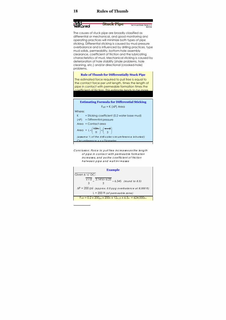
SSttuucck k PPiippee
The causes of stuck pipe are broadly classified as
differential or mechanical, and good monitoring and
operating practices will minimize both types of pipe
sticking. Differential sticking is caused by mud pressure
overbalance and is influenced by drilling practices, type
mud solids, permeability, bottom-hole assembly
clearance, coefficient of friction and the lubricating
characteristics of mud. Mechanical sticking is caused by
deterioration of hole stability (shale problems, hole
cleaning, etc.) and/or directional (crooked-hole)
problems.
Rule of Thumb for Differentially Stuck Pipe
The estimated force required to pull free is equal to
the contact force per unit length, times the length of
pipe in contact with permeable formation times the
coefficient of friction. This estimate tends to be more
accurate in a straight hole than in a directional well.
Estimating Formula for Differential Sticking
Fdiff = K (∆P) Area
Where:
K = Sticking coefficient (0.2 water base mud)
(∆P) = Differential pressure
Area = Contact area
Area = ⎟⎟ ⎠
⎞⎜⎜⎝
⎛ ×π×⎟⎟
⎠
⎞⎜⎜⎝
⎛ ×
3
d
ft
.in12L
(a ssum e⅓ o f the d rill c o lla r c irc um fere nc e is b urie d )
Circumference = π x Diameter
Conc lusio n: Fo rc e to p ull fre e inc re a se s a s the le ng th
o f p ip e in c on ta c t w ith pe rm ea b le fo rm a t ion
inc re a se s, a nd a s the c o e f fic ie nt o f f ric t io n
b e tw ee n p ip e a nd w a ll inc re a ses.
Example
Given 6 ¼" DC:
545.6
3
25.61416.3
3
d=
×=
×π ( ro und to 6.5)
∆P = 200 psi (a p p ro x. 0.5 p p g o verb a la nc e a t 8,000 ft )
L = 200 ft (o f p erm ea b le zo ne)
Fdiff = 0.2 x 200psi x 200ft x 12in./ft x 6.5in. = 624,000lbs
8/15/2019 Technical Data Book - Well Control 2004
http://slidepdf.com/reader/full/technical-data-book-well-control-2004 20/66
Rules of Thumb 19
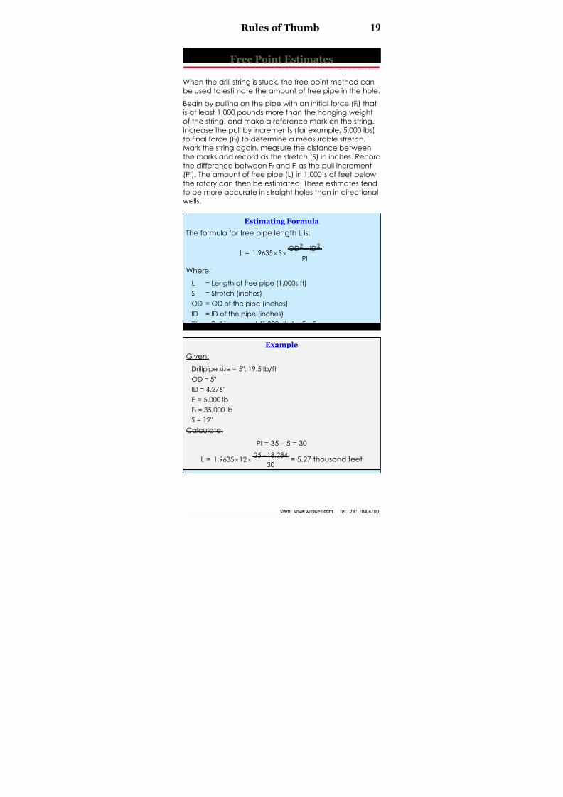
FFrreeee PPooiinntt EEssttiimmaatteess
When the drill string is stuck, the free point method can
be used to estimate the amount of free pipe in the hole.
Begin by pulling on the pipe with an initial force (Fi) that
is at least 1,000 pounds more than the hanging weightof the string, and make a reference mark on the string.
Increase the pull by increments (for example, 5,000 lbs)
to final force (Ff) to determine a measurable stretch.
Mark the string again, measure the distance between
the marks and record as the stretch (S) in inches. Record
the difference between Ff and Fi as the pull increment
(PI). The amount of free pipe (L) in 1,000’s of feet below
the rotary can then be estimated. These estimates tend
to be more accurate in straight holes than in directional
wells.
Estimating Formula
The formula for free pipe length L is:
L =PI
IDODS9635.1
22 −××
Where:
L = Length of free pipe (1,000s ft)S = Stretch (inches)
OD = OD of the pipe (inches)
ID = ID of the pipe (inches)
PI = Pull increment (1,000s lbs) = Ff - Fi
Example
Given:
Drillpipe size = 5", 19.5 lb/ft
OD = 5"
ID = 4.276"
Fi = 5,000 lbFf = 35,000 lb
S = 12"
Calculate:
PI = 35 – 5 = 30
L =30
284.1825129635.1 −×× = 5.27 thousand feet
8/15/2019 Technical Data Book - Well Control 2004
http://slidepdf.com/reader/full/technical-data-book-well-control-2004 21/66
20 Rules of Thumb
EEssttiimmaattiinngg TTeemmppeerraattuurree DDrroopp A A ccrroossss
aa CChhook k ee oorr OOrriif f iiccee
Rule of Thumb
The temperature drop across a choke or orifice is
about one degree Fahrenheit (F) per each pressuredrop of one atmosphere (rounded at 15 psi).
Estimating Formula
( )F1
psi15
psiPP T
Lhdrop °×
−=
Where:
Tdrop = Temperature drop (degrees)
Ph = Gas pressure before the choke (psi)
PL = Gas pressure after the choke (psi)
Example
Calculate temperature drop if the gas pressure is
reduced from 1,000 psi to 500 psi across a choke.
Tdrop = F115
)500000,1(°×
−
= 33 x 1°F = 33°F temperature drop
EEssttiimmaattiinngg GGaass W W eellll FFlloo w w R R aatteess
Rule of Thumb
The approximate flow rate (in mmscfd) of a gas well
through a blowdown line choke can be estimated by
multiplying 24 hours/day, times the tubing pressure
plus 15, times the square of the choke size in inches
and divide by 1,000.
Estimating Formula
Q =1,000
)(D x15)(P x24 2chL +
Where:Q = Flowrate (mmscfd)
PL = Pressure upstream of choke (psi)
Dch = Choke size (inches)

8/15/2019 Technical Data Book - Well Control 2004
http://slidepdf.com/reader/full/technical-data-book-well-control-2004 22/66
Rules of Thumb 21
ExampleCalculate the estimated flowrate of a gas well, given
that tubing pressure is 3,500 psi, and choke size is ¼ ".
Q =1,000
(0.25) x15)(3,500 x24 2+ = 5.273 mmscfd
PPiippee EElloonnggaattiioonn DDuuee ttoo TTeemmppeerraattuurree
Since the well has higher temperatures than the air
above ground, an elongation will take place.
Rule of Thumb
Pipe will elongate about 0.83 inches, per 100 feet of
length, per 100 degree F increase in temperature.
Knowing the surface temperature and the average
temperature of the well, the elongation can be
estimated.
No te : Elo ng a t io n (st re tc h) is a lso c a used b y the ha ng ing
w e ig h t o f p ip e .
Estimating Formulas
FSTTVDft100
F1BHT °+⎟⎟
⎠
⎞⎜⎜⎝
⎛ ×
°=
2
STBHTTa
+=
∆T = Ta – Surface Temp
TLF
in/in0000069.012L ft/inT ∆××
°×=∆
83.0
F100
T
ft100
LLT ×
°
∆×=∆
Where:
BHT = Bottomhole temperature (°F)
Depth = True vertical depth (ft)
ST = Surface temperature (°F)
Ta = Average temperature (°F)
∆T = Change in average temperature (°F)
∆LT = Elongation (inches)
L = Length of pipe (ft)

8/15/2019 Technical Data Book - Well Control 2004
http://slidepdf.com/reader/full/technical-data-book-well-control-2004 23/66
PipeSizeIn.
Nom. Wt.
Lb/Ft
WallThick.
In.
PipeIDIn.
PlainEnd Wt.
Lb/Ft
Upset Wt.
Lb
PipeEnd
Dia. ID
2 ⅞ 10.40 0.362 2.151 9.72 2.40 2.151
3 ½ 13.30 0.368 2.764 12.31 4.00 2.602 3 ½ 15.50 0.449 2.602 14.63 2.80 2.602
I
5 19.50 0.362 4.276 17.93 16.80 3.653
4 14.00 0.330 3.340 12.93 14.40 3.063 4 ½ 16.60 0.337 3.826 14.98 17.20 3.563
I4 ½ 20.00 0.430 3.640 18.69 17.60 2.813 5 19.50 0.362 4.276 17.93 16.80 3.563
5 25.60 0.500 4.000 24.03 15.40 3.313 5 25.60 0.500 4.000 24.03 15.40 3.313
5 ½ 21.90 0.361 4.778 19.81 21.00 3.813 I
5 ½ 21.90 0.361 4.778 19.81 21.00 3.813 5 ½ 24.70 0.415 4.670 22.54 18.40 3.813
6 ⅝ 25.20 0.330 5.965 22.19 25.87 5.315 6 ⅝ 27.70 0.362 5.901 24.21 24.00 5.315
8/15/2019 Technical Data Book - Well Control 2004
http://slidepdf.com/reader/full/technical-data-book-well-control-2004 24/66
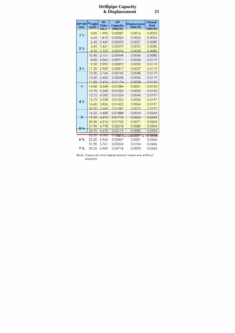
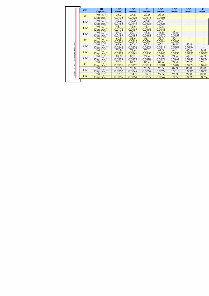
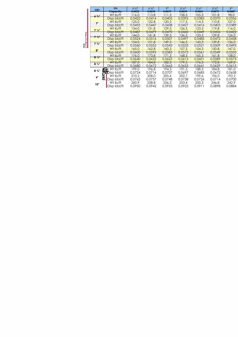
Drillpipe Capacity
& Displacement 23
DP OD(In).
eight(ppf)
IDTube(In.)
DPCapacity(bbl/ft)
Displacement(bbl/ft)
Closed-End(bbl/ft)
4.85 1.995 0.00387 0.0016 0.00552 ⅜
6.65 1.815 0.00320 0.0025 0.0055
6.45 2.469 0.00592 0.0021 0.0080
6.85 2.441 0.00579 0.0022 0.00808.35 2.323 0.00524 0.0028 0.0080
2 ⅞
10.40 2.151 0.00449 0.0040 0.0080
8.50 3.063 0.00911 0.0028 0.0119
9.50 2.992 0.00870 0.0035 0.0119
11.20 2.900 0.00817 0.0037 0.0119
13.30 2.764 0.00742 0.0048 0.0119
3 ½
15.50 2.602 0.00658 0.0056 0.0119
11.85 3.476 0.01174 0.0038 0.0155
14.00 3.340 0.01084 0.0051 0.01554
15.70 3.240 0.01020 0.0053 0.0155
12.75 4.000 0.01554 0.0046 0.019713.75 3.958 0.01522 0.0050 0.0197
16.60 3.826 0.01422 0.0064 0.01974 ½
20.00 3.640 0.01287 0.0073 0.0197
16.25 4.408 0.01888 0.0054 0.0243
19.50 4.276 0.01776 0.0065 0.02435
20.50 4.214 0.01725 0.0071 0.0243
21.90 4.778 0.02218 0.0080 0.02945 ½
24.70 4.670 0.02119 0.0082 0.0294
22.20 6.065 0.03573 0.0069 0.0426
25.20 5.965 0.03457 0.0081 0.04266 ⅝
31.90 5.761 0.03224 0.0104 0.04267 ⅝ 29.25 6.969 0.04718 0.0093 0.0565
Note : C a p a c it y a nd d isp la c em en t va lue a re w ithou t
tool joint.
8/15/2019 Technical Data Book - Well Control 2004
http://slidepdf.com/reader/full/technical-data-book-well-control-2004 25/66
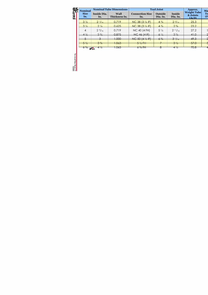
Nominal Tube Dimensions Nominal
SizeIn.
Inside Dia.In.
WallThickness In.
Connection In.
3 ½ 2 1/16 0.719 NC 38 (3 ½
3 ½ 2 ¼ 0.625 NC 38 (3 ½
4 2 9/16 0.719 NC 40 (4 F
4 ½ 2 ¾ 0.875 NC 46 (4 I
5 3 1.000 NC 50 (4 ½
5 ½ 3 ⅜ 1.063 5 ½ FH
6 ⅝ 4 ½ 1.063 6 ⅝ FH
8/15/2019 Technical Data Book - Well Control 2004
http://slidepdf.com/reader/full/technical-data-book-well-control-2004 26/66
8/15/2019 Technical Data Book - Well Control 2004
http://slidepdf.com/reader/full/technical-data-book-well-control-2004 27/66

8/15/2019 Technical Data Book - Well Control 2004
http://slidepdf.com/reader/full/technical-data-book-well-control-2004 28/66
Drill Collar Capacity
& Displacement 27
DC OD(In.)
DC ID(In.)
DC Capacity(bbl/ft)
Steel Displ.(bbl/ft)
Closed-End(bbl/ft)
3 ⅛ 1.250 0.00152 0.0080 0.0095
3 ¾ 1.500 0.00219 0.0115 0.0137
4 ⅛ 2.000 0.00389 0.0126 0.0165
4 ¾ 2.000 0.00389 0.0181 0.0219
6 2.250 0.00492 0.0301 0.03506 ¼ 2.500 0.00607 0.0318 0.0379
6 ½ 2.500 0.00607 0.0350 0.0410
8 2.813 0.00768 0.0545 0.0622
8 ¼ 2.875 0.00803 0.0589 0.0661
8 ½ 2.875 0.00803 0.0622 0.0629
9 2.875 0.00803 0.0707 0.0787
9 ½ 2.875 0.00803 0.0796 0.0877
10 2.875 0.00803 0.0891 0.0971
10 ½ 2.875 0.00803 0.0991 0.1071
11 2.875 0.00803 0.1095 0.1175
11 ½ 2.875 0.00803 0.1204 0.128512 2.875 0.00803 0.1319 0.1399

8/15/2019 Technical Data Book - Well Control 2004
http://slidepdf.com/reader/full/technical-data-book-well-control-2004 29/66
8/15/2019 Technical Data Book - Well Control 2004
http://slidepdf.com/reader/full/technical-data-book-well-control-2004 30/66
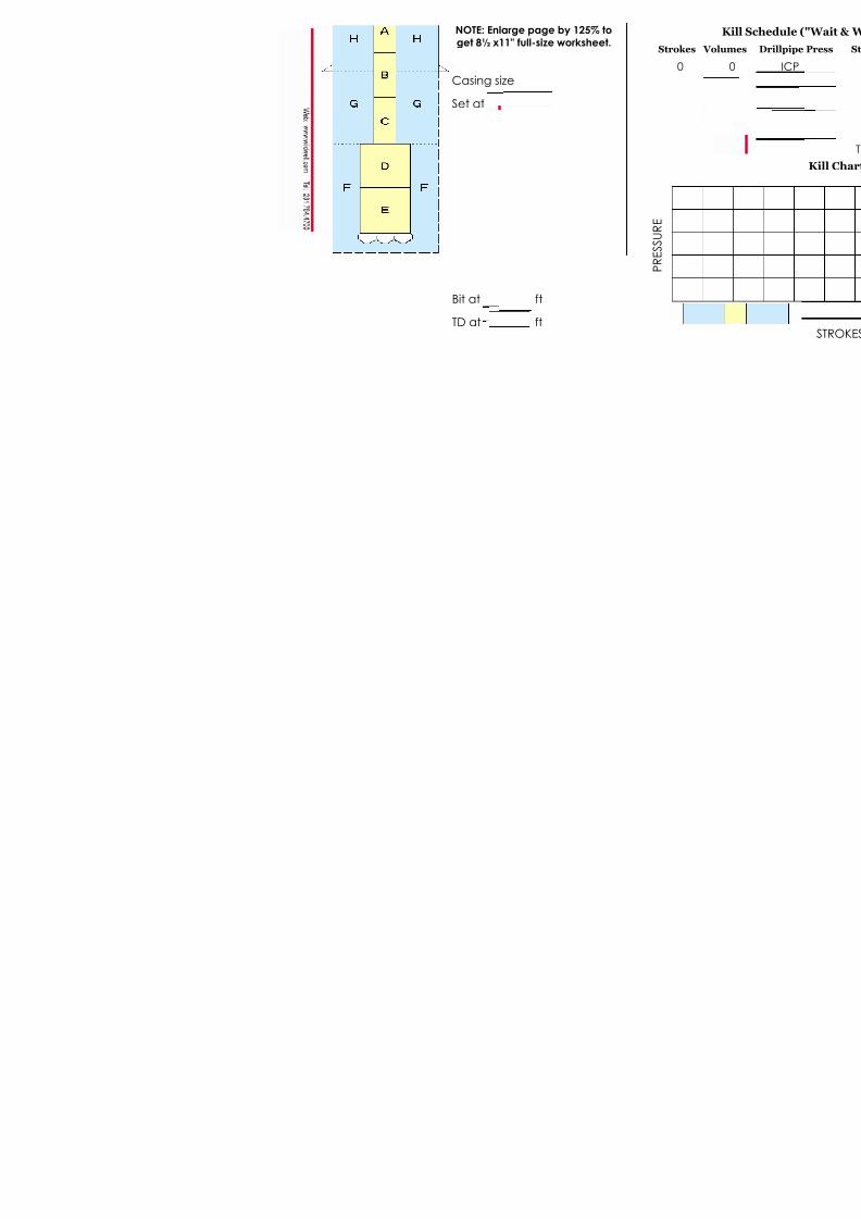
Casing size
Set at
Bit at ft
TD at ft
NOTE: Enlarge page by 125% to
get 8½ x11" full-size worksheet
8/15/2019 Technical Data Book - Well Control 2004
http://slidepdf.com/reader/full/technical-data-book-well-control-2004 31/66
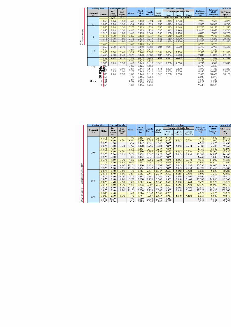
Tubing Size Normal Weight
NominalIn.
OD In.
T&CNon-upsetlb/ft
T&CUpsetlb/ft
Grade WallThick.
In.
InsideDia. In.
DriftDia In.
1.050 1.14 1.20 H-40 0.113 .824 .730
1.050 1.14 1.20 J-55 0.113 .824 .730
1.050 1.14 1.20 C-75 0.113 .824 .730 ¾
1.050 1.14 1.20 N-80 0.113 .824 .730 1.315 1.70 1.80 H-40 0.133 1.049 .955 1.315 1.70 1.80 J-55 0.133 1.049 .955 1.315 1.70 1.80 C-75 0.133 1.049 .955
1
1.315 1.70 1.80 N-80 0.133 1.049 .955 1.660 H-40 0.125 1.410
1.660 2.30 2.40 H-40 0.140 1.380 1.286 1.660 J-55 0.125 1.410 1.660 2.30 2.40 J-55 0.140 1.380 1.286 1.660 2.30 2.40 C-75 0.140 1.380 1.286
1 ¼
1.660 2.30 2.40 N-80 0.140 1.380 1.286 1.900 H-40 0.125 1.850 1.900 2.75 2.90 H-40 0.145 1.610 1.516 1.900 J-55 0.125 1.650 1.900 2.75 2.90 J-55 0.145 1.610 1.516 1.900 2.75 2.90 C-75 0.145 1.610 1.516
1 ½
1.900 2.75 2.90 N-80 0.145 1.610 1.516 2.063 H-40 0.156 1.751 2.063 J-55 0.156 1.751 2.063 C-75 0.156 1.751
2 1/16
2.063 N-80 0.156 1.751
8/15/2019 Technical Data Book - Well Control 2004
http://slidepdf.com/reader/full/technical-data-book-well-control-2004 32/66

8/15/2019 Technical Data Book - Well Control 2004
http://slidepdf.com/reader/full/technical-data-book-well-control-2004 33/66

8/15/2019 Technical Data Book - Well Control 2004
http://slidepdf.com/reader/full/technical-data-book-well-control-2004 34/66

8/15/2019 Technical Data Book - Well Control 2004
http://slidepdf.com/reader/full/technical-data-book-well-control-2004 35/66
8/15/2019 Technical Data Book - Well Control 2004
http://slidepdf.com/reader/full/technical-data-book-well-control-2004 36/66
Burst PressureCasing OD(In.)
Weight(ppf) H40 J/K 55 C75 N
9.5 4,380 11.6 5,350 7,290 7
13.5 6,200 8,460 9
4 ½
15.1 7,210 9,830 1011.5 4,240 13.0 4,870 6,640 715.0 5,700 7,770 8
5
18.0 6,970 9,500 1014.0 4,270 5,820
15.5 4,810 6,560 717.0 5,320 7,250 720.0 6,310 8,610 9
5 ½
23.0 7,270 9,900 1020.0 4,180 624.0 5,110 6,970 76 ⅝
28.0 6,060 8,260 8
20.0 2,720 3,740 5,100 23.0 4,360 5,940 626.0 4,980 6,790 729.0 5,610 7,650 832.0 6,230 8,490 9
7
35.0 6,850 9,340 9

8/15/2019 Technical Data Book - Well Control 2004
http://slidepdf.com/reader/full/technical-data-book-well-control-2004 37/66
Burst PressureCasing OD(In.)
Weight(ppf) H40 J/K 55 C75 N
26.4 4,140 5,650 629.7 6,450 6
33.7 5,430 7,400 7
7 ⅝
39.0 8,610 924.0 2,950 32.0 2,860 3,930 5,360 536.0 4,460 6,090 6
8 ⅝
40.0 5,020 6,850 736.0 2,560 3,520 4,800 540.0 3,950 5,390 5
43.5 4,350 5,930 647.0 4,720 6,440 6
9 ⅝
53.5 7,430 740.5 2,280 3,130 4,270 45.5 3,580 4,880 551.0 4,030 5,490 555.5 4,430 6,040 6
60.7 4,880 6,650 765.7 5,330 7,260 7
10 ¾
71.1 47.0 3,070 4,190 54.0 3,560 4,860 11 ¾60.0 4,010 5,460 5

8/15/2019 Technical Data Book - Well Control 2004
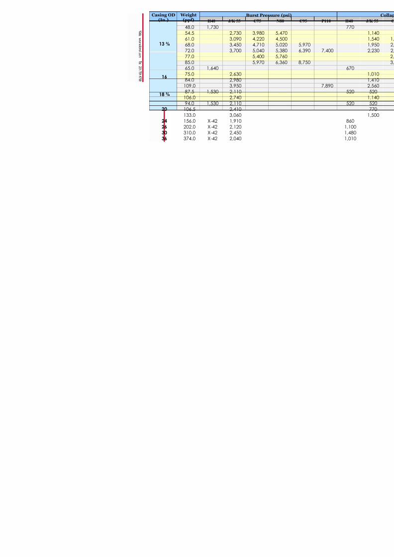
http://slidepdf.com/reader/full/technical-data-book-well-control-2004 38/66
Burst PressureCasing OD(In.)
Weight(ppf) H40 J/K 55 C75 N
48.0 1,730
54.5 2,730 3,980 5
61.0 3,090 4,220 468.0 3,450 4,710 5
72.0 3,700 5,040 5
77.0 5,400 5
13 ⅜
85.0 5,970 6
65.0 1,640
75.0 2,630
84.0 2,980 16
109.0 3,950
87.5 1,530 2,110 18 ⅝
106.0 2,740
94.0 1,530 2,110
106.5 2,410 20
133.0 3,060
24 156.0 X-42 1,910 26 202.0 X-42 2,120
30 310.0 X-42 2,450
36 374.0 X-42 2,040
8/15/2019 Technical Data Book - Well Control 2004
http://slidepdf.com/reader/full/technical-data-book-well-control-2004 39/66
38 Casing Capacity
Casing OD(In.) Weight(ppf) Casing ID(In.) Capacity(bbl/ft) Displacement(bbl/ft)
9.5 4.090 0.0163 0.0035
11.6 4.000 0.0155 0.0042
13.5 3.920 0.0149 0.00494 ½
15.1 3.826 0.0142 0.005511.5 4.560 0.0202 0.0042
13.0 4.494 0.0196 0.0047
15.0 4.408 0.0189 0.00555
18.0 4.276 0.0178 0.0066
14.0 5.012 0.0244 0.0051
15.5 4.950 0.0238 0.0056
17.0 4.892 0.0233 0.0062
20.0 4.778 0.0222 0.0073
5 ½
23.0 4.670 0.0212 0.0084
20.0 6.049 0.0355 0.0071
24.0 5.921 0.0341 0.00876 ⅝
28.0 5.791 0.0326 0.0102
20.0 6.456 0.0405 0.0073
23.0 6.366 0.0394 0.0084
26.0 6.276 0.0383 0.0095
29.0 6.184 0.0372 0.0106
32.0 6.094 0.0361 0.0116
7
35.0 6.004 0.0350 0.0127
26.4 6.969 0.0472 0.009629.7 6.875 0.0459 0.0108
33.7 6.765 0.0445 0.01237 ⅝
39.0 6.624 0.0426 0.0142
24.0 8.098 0.0637 0.0086
32.0 7.921 0.0610 0.0116
36.0 7.825 0.0595 0.01318 ⅝
40.0 7.725 0.0580 0.0146
36.0 8.921 0.0773 0.0131
40.0 8.835 0.0758 0.0146
43.5 8.755 0.0745 0.0158
47.0 8.681 0.0732 0.0171
9 ⅝
53.5 8.535 0.0708 0.0195

8/15/2019 Technical Data Book - Well Control 2004
http://slidepdf.com/reader/full/technical-data-book-well-control-2004 40/66
8/15/2019 Technical Data Book - Well Control 2004
http://slidepdf.com/reader/full/technical-data-book-well-control-2004 41/66
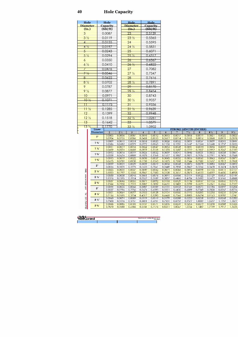
40 Hole Capacity
HoleDiameter(In.)
HoleCapacity(bbl/ft)
HoleDiameter(In.)
HoleCapacity(bbl/ft)
3 0.0087 23 0.5139
3 ½ 0.0119 23 ½ 0.5365
4 0.0155 24 0.5595
4 ½ 0.0197 24 ½ 0.58315 0.0243 25 0.6071
5 ½ 0.0294 25 ½ 0.6317
6 0.0350 26 0.6567
6 ½ 0.0410 26 ½ 0.6822
7 0.0476 27 0.7082
7 ½ 0.0546 27 ½ 0.7347
8 0.0622 28 0.7616
8 ½ 0.0702 28 ½ 0.7891
9 0.0787 29 0.8170
9 ½ 0.0877 29 ½ 0.8454
10 0.0971 30 0.874310 ½ 0.1071 30 ½ 0.9037
11 0.1175 31 0.9336
11 ½ 0.1285 31 ½ 0.9639
12 0.1399 32 0.9948
12 ½ 0.1518 32 ½ 1.0261
13 0.1642 33 1.0579
13 ½ 0.1770 33 ½ 1.0902
14 0.1904 34 1.1230
14 ½ 0.2042 34 ½ 1.1563
15 0.2086 35 1.1900
15 ½ 0.2334 35 ½ 1.224316 0.2487 36 1.2590
16 ½ 0.2645 36 ½ 1.2942
17 0.2807 37 1.3299
17 ½ 0.2975 37 ½ 1.3661
18 0.3147 38 1.4028
18 ½ 0.3325 38 ½ 1.4399
19 0.3507 39 1.4776
19 ½ 0.3694 39 ½ 1.5157
20 0.3886 40 1.5543
20 ½ 0.4082 40 ½ 1.5934
21 0.4284 41 1.633021 ½ 0.4490 41 ½ 1.6731
22 0.4702 42 1.7136
22 ½ 0.4918 42 ½ 1.7547

8/15/2019 Technical Data Book - Well Control 2004
http://slidepdf.com/reader/full/technical-data-book-well-control-2004 42/66

8/15/2019 Technical Data Book - Well Control 2004
http://slidepdf.com/reader/full/technical-data-book-well-control-2004 43/66

8/15/2019 Technical Data Book - Well Control 2004
http://slidepdf.com/reader/full/technical-data-book-well-control-2004 44/66
8/15/2019 Technical Data Book - Well Control 2004
http://slidepdf.com/reader/full/technical-data-book-well-control-2004 45/66
44 Mud Weights
lb/gal lb/ft3 Kg/m3 SpecificGravity
GradientDepth
(psi/ft)
GradientDepth
(kPa/m)
8.34 62.38 999.3 1.00 0.434 9.8
8.5 63.58 1018.5 1.02 0.442 10.0
8.6 64.32 1030.5 1.03 0.447 10.1
8.7 65.07 1042.4 1.04 0.452 10.2
8.8 65.82 1054.4 1.05 0.458 10.48.9 66.57 1066.4 1.07 0.463 10.5
9.0 67.31 1078.4 1.08 0.468 10.6
9.1 68.06 1090.4 1.09 0.473 10.7
9.2 68.81 1102.3 1.10 0.478 10.8
9.3 69.56 1114.3 1.12 0.484 10.9
9.4 70.31 1126.3 1.13 0.489 11.1
9.5 71.05 1138.3 1.14 0.494 11.29.6 71.80 1150.3 1.15 0.499 11.3
9.7 72.55 1162.3 1.16 0.504 11.4
9.8 73.30 1174.2 1.18 0.510 11.5
9.9 74.05 1186.2 1.19 0.515 11.6
10.0 74.79 1198.2 1.20 0.520 11.8
10.1 75.54 1210.2 1.21 0.525 11.910.2 76.29 1222.2 1.22 0.530 12.0
10.3 77.04 1234.2 1.24 0.536 12.1
10.4 77.79 1246.1 1.25 0.541 12.2
10.5 78.53 1258.1 1.26 0.546 12.4
10.6 79.28 1270.1 1.27 0.551 12.5
10.7 80.03 1282.1 1.28 0.556 12.6
10.8 80.78 1294.1 1.29 0.562 12.710.9 81.53 1306.0 1.31 0.567 12.8
11.0 82.27 1318.0 1.32 0.572 12.9
11.1 83.02 1330.0 1.33 0.577 13.1
11.2 83.77 1342.0 1.34 0.582 13.2
11.3 84.52 1354.0 1.36 0.588 13.3
11.4 85.27 1366.0 1.37 0.593 13.4
11.5 86.01 1377.9 1.38 0.598 13.5
11.6 86.76 1389.9 1.39 0.603 13.6
11.7 87.51 1401.9 1.40 0.608 13.8
11.8 88.26 1413.9 1.41 0.614 13.9
11.9 89.01 1425.9 1.43 0.619 14.0
12.0 89.75 1437.8 1.44 0.624 14.1
12.1 90.50 1449.8 1.45 0.629 14.212.2 91.25 1461.8 1.46 0.634 14.4
12.3 92.00 1473.8 1.48 0.640 14.5
12.4 92.74 1485.8 1.49 0.645 14.6
12.5 93.49 1497.8 1.50 0.650 14.7
12.6 94.24 1509.7 1.51 0.655 14.8
12.7 94.99 1521.7 1.52 0.660 14.9
12.8 95.74 1533.7 1.53 0.666 15.1
12.9 96.48 1545.7 1.55 0.671 15.2
13.0 97.23 1557.7 1.56 0.676 15.3
13.1 97.98 1569.6 1.57 0.681 15.4
13.2 98.73 1581.6 1.58 0.686 15.5

8/15/2019 Technical Data Book - Well Control 2004
http://slidepdf.com/reader/full/technical-data-book-well-control-2004 46/66
Mud Weights 45
lb/gal lb/ft3 Kg/m3 SpecificGravity
GradientDepth
(psi/ft)
GradientDepth
(kPa/m)
13.3 99.48 1593.6 1.60 0.692 15.6
13.4 100.22 1605.6 1.61 0.697 15.8
13.5 100.97 1617.6 1.62 0.702 15.9
13.6 101.72 1629.6 1.63 0.707 16.0
13.7 102.47 1641.5 1.64 0.712 16.113.8 103.22 1653.5 1.65 0.718 16.2
13.9 103.96 1665.5 1.67 0.723 16.4
14.0 104.71 1677.5 1.68 0.728 16.5
14.1 105.46 1689.5 1.69 0.733 16.6
14.2 106.21 1701.5 1.70 0.738 16.7
14.3 106.96 1713.4 1.72 0.744 16.8
14.4 107.70 1725.4 1.73 0.749 16.914.5 108.45 1737.4 1.74 0.754 17.1
14.6 109.20 1749.4 1.75 0.759 17.2
14.7 109.95 1761.4 1.76 0.764 17.3
14.8 110.70 1773.3 1.78 0.770 17.4
14.9 111.44 1785.3 1.79 0.775 17.5
15.0 112.19 1797.3 1.80 0.780 17.615.1 112.94 1809.3 1.81 0.785 17.8
15.2 113.69 1821.3 1.82 0.790 17.9
15.3 114.44 1833.3 1.84 0.796 18.0
15.4 115.18 1845.2 1.85 0.801 18.1
15.5 115.93 1857.2 1.86 0.806 18.2
15.6 116.68 1869.2 1.87 0.811 18.3
15.7 117.43 1881.2 1.88 0.816 18.515.8 118.18 1893.2 1.90 0.822 18.6
15.9 118.92 1905.1 1.91 0.827 18.7
16.0 119.67 1917.1 1.92 0.832 18.8
16.1 120.42 1929.1 1.93 0.837 18.9
16.2 121.17 1941.1 1.94 0.842 19.1
16.3 121.91 1953.1 1.96 0.846 19.2
16.4 122.66 1965.1 1.97 0.853 19.3
16.5 123.41 1977.0 1.98 0.858 19.4
16.6 124.16 1989.0 2.00 0.863 19.5
16.7 124.91 2001.0 2.01 0.868 19.6
16.8 125.65 2013.0 2.02 0.874 19.8
16.9 126.40 2025.0 2.03 0.879 19.9
17.0 127.15 2036.9 2.04 0.884 20.017.1 127.90 2048.9 2.05 0.889 20.1
17.2 128.65 2060.9 2.06 0.894 20.2
17.3 129.39 2072.9 2.08 0.900 20.3
17.4 130.14 2084.9 2.09 0.905 20.5
17.5 130.89 2096.9 2.10 0.910 20.6
17.6 131.64 2108.8 2.11 0.915 20.7
17.7 132.39 2120.8 2.12 0.920 20.8
17.8 133.13 2132.8 2.14 0.926 20.9
17.9 133.88 2144.8 2.15 0.931 21.1
18.0 134.63 2156.8 2.16 0.936 21.2
18.1 135.38 2168.8 2.17 0.941 21.3

8/15/2019 Technical Data Book - Well Control 2004
http://slidepdf.com/reader/full/technical-data-book-well-control-2004 47/66
46 Mud Weights
lb/gal lb/ft3 Kg/m3 SpecificGravity
GradientDepth
(psi/ft)
GradientDepth
(kPa/m)
18.2 136.13 2180.7 2.18 0.946 21.4
18.3 136.87 2192.7 2.20 0.952 21.5
18.4 137.62 2204.7 2.21 0.957 21.6
18.5 138.37 2216.7 2.22 0.962 21.8
18.6 139.12 2228.7 2.23 0.967 21.918.7 139.87 2240.6 2.24 0.972 22.0
18.8 140.61 2252.6 2.26 0.978 22.1
18.9 141.36 2264.6 2.27 0.983 22.2
19.0 142.11 2276.6 2.28 0.988 22.3
19.1 142.86 2288.6 2.29 0.993 22.5
19.2 143.61 2300.6 2.30 0.998 22.6
19.3 144.35 2312.5 2.32 1.004 22.719.4 145.10 2324.5 2.33 1.009 22.8
19.5 145.85 2336.5 2.34 1.014 22.9
19.6 146.60 2348.5 2.35 1.019 23.1
19.7 147.34 2360.5 2.36 1.024 23.2
19.8 148.09 2372.4 2.38 1.030 23.3
19.9 148.84 2384.4 2.39 1.035 23.420.0 149.59 2396.4 2.40 1.040 23.5
Specifications for BOP Flanges, RingGaskets, and Flange Bolts & Nuts
NOTE: A c c e p ta b le f la ng e ring
g a ske t m a te ria l fo r sw e e t o il
a p p lic a t io ns is lo w -c a rb o n ste e l a nd
fo r so ur o il o r g a s is ty p e 316 sta in le ss
o r typ e 304 sta in le ss ste e l. ASTM A -
193 G ra d e B/ M w ith a m a xim um
Ro c kwe ll Ha rd ne ss o f 22 ma y b ea c c ep t ab le b u t shou ld b e d e ra t ed
a s p e r Ta b le 1.4B o f API Sp e c 6A .
Sp e c if ic a t io ns a s p e r API Sp e c 6A
"We llhe a d Eq uip m ent".
StackRating Approved Flanges ApprovedRing Gaskets BoltSpec. NutSpec.
2000 psi
and
3000 psi
API type 6B with
type R flat
Bottom Groove
API Type RX
ASTM
Grade
B-7
ASTM
Grade
2-H
5000 psi
API Type 6B
with Type R Flat
Bottom grooveor
API Type 6BX with
Type BX Groove
API Type RX
orAPI Type BX
with Type
6BX Flange
ASTMGrade
B-7
ASTMGrade
2-H
10,000
psi
API Type 6BX with
Type BX GrooveAPI Type BX
ASTM
Grade
B-7
ASTM
Grade
2-H
Bolt Size(In.)
Torque(Ft-Lb)
¾ - 10 UNC 200
⅞ - 9 UNC 325
1 - 8 UNC 475
1 ⅛ - 8 UN 6001 ½ - 8 UN 1400
1 ⅝ - 8 UN 1700
1 ¾ - 8 UN 2040
1 ⅞ - 8 UN 3220

8/15/2019 Technical Data Book - Well Control 2004
http://slidepdf.com/reader/full/technical-data-book-well-control-2004 48/66
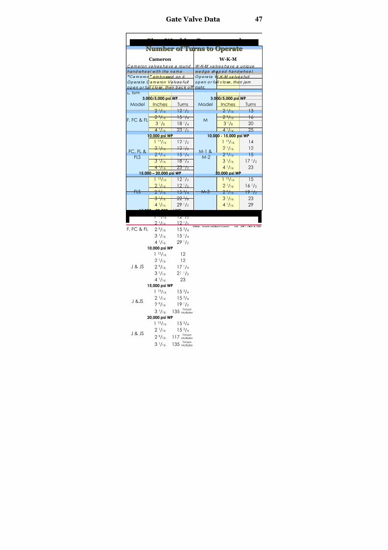
Gate Valve Data 47
SSiizzee,, W W oorrk k iinngg PPrreessssuurree aanndd
NNuumm b beerr oof f TTuurrnnss ttoo OOppeerraattee
Cameron W-K-M
Cam eron va lves ha ve a round
hand whe e l w it h the nam e
“Ca m e ro n” em b o ssed on it .O p era te C am e ron Va lves fu ll
o p e n o r full c lo se , then b ac k o ff
¼ turn .
W-K-M va lve s ha ve a un iq ue
we d ge shap ed hand whee l.
O p e ra te W-K-M va lve s fullo p e n o r full c lo se , then jam
tight .
3,000/5,000 psi WP 3,000/5,000 psi WP
Model Inches Turns Model Inches Turns
2 1/16 12 1/2 2 1/16 13
29
/16 151
/4 29
/16 163 1/8 18 1/4 3 1/8 20
F, FC & FL
4 1/16 23 1/2
M
4 1/16 25
10,000 psi WP 10,000 - 15,000 psi WP
1 13/16 12 1/2 1 13/16 14
2 1/16 12 1/2 2 1/16 12
2 9/16 15 1/4 2 9/16 15
3 1/16 18 1/4 3 1/16 17 1/2
FC, FL &
FLS
4 1/16 23 1/2
M-1 &
M-2
4 1/16 23
15,000 – 20,000 psi WP 20,000 psi WP
1 13/16 12 1/2 1 13/16 15
2 1/16 12 1/2 2 1/16 16 1/2
2 9/16 15 3/4 2 9/16 19 1/2
3 1/16 22 7/8 3 1/16 23
FLS
4 1/16 29 1/2
M-3
4 1/16 29
15,000 – 20,000 psi WP
1 13/16 12 1/2
2 1/16 12 1/2
2 9/16 15 3/4
31
/16 151
/4
F, FC & FL
4 1/16 29 1/2
10,000 psi WP
1 13/16 12
2 1/16 12
2 9/16 17 1/4
3 1/16 21 1/2
J & JS
4 1/16 23
15,000 psi WP
1 13/16 15 3/4
2 1/16 15 3/4
2 9/16 19 1/2 J &JS
3 1/16 135Torque
Multiplier 20,000 psi WP
1 13/16 15 3/4
2 1/16 15 3/4
2 9/16 117Torque
Multiplier J & JS
3 1/16 135Torque
Multiplier

8/15/2019 Technical Data Book - Well Control 2004
http://slidepdf.com/reader/full/technical-data-book-well-control-2004 49/66
48 Gate Valve Data
SSiizzee,, W W oorrk k iinngg PPrreessssuurree aanndd
NNuumm b beerr oof f TTuurrnnss ttoo OOppeerraattee
Ingram Cactus McEvoy
Ing ram C a c tus va lves ha ve
a round ha ndw hee l w ith
th ree sp okes a nd the na m e“Ing ra m Ca c tus” em b o sse d
o n it . O p e ra te Ing ra m
Ca c tus va lve s Mo d e l 205
a nd 215 full o p e n o r full
c lo se , the n jam tig ht .
Op era te M o d e l 405 a nd 315
full o p e n o r full c lo se , thenb a c k o ff ¼ turn .
M c Evo y va lves ha ve a ro und
hand whee l w it h the nam e
“Mc Evo y” em b o ssed o n it .O p e ra te Mc Evo y va lve s fu ll
o p e n o r full c lo se , th en bac k
o ff ¼ tu rn .
2,000/5,000 psi WP 2,000/3,000/5,000 psi WP
Model Inches Turns Model Inches Turns
2 1/16 13 2 1/16 13
2 9/16 16 2 9/16 16
3 1/8 20 3 1/8 18205
4 1/16 25
C
4 1/16 17
2,000/5,000 psi WP 10,000 psi WP
2 1/16 16 1 13/16 11
2 9/16 19 2 1/16 13
3 1/8 23 2 9/16 10 1/2
4 1/16 24 1/2 3 1/16 12 1/2
405 E
4 1/16 1710,000 – 15,000 psi WP 15,000 psi WP
1 13/16 14 1 13/16 11
2 1/16 12 2 1/16 9
2 9/16 15 2 9/16 10 1/2
3 1/16 17 1/2 3 1/16 26
215
41
/16 23
E
41
/16 ---10,000 – 15,000 psi WP 10,000 psi WP
1 13/16 16 1 13/16 11
2 1/16 18 2 1/16 9
2 9/16 17 2 9/16 10 1/2
3 1/16 24 3 1/16 12 3/4
315
4 1/16 21
E-2
4 1/16 17 1/8 15,000 psi WP
1 13/16 7 3/4
2 1/16 9
2 9/16 10 1/2
3 1/16 12 3/4
E-2
4 1/16 17 1/8
8/15/2019 Technical Data Book - Well Control 2004
http://slidepdf.com/reader/full/technical-data-book-well-control-2004 50/66
NominalFlange Size
(In.)
ServiceRating (psi)
StandardRing Gasket
Number
Energized RingNumber
OldDe
10M BX151
15M BX151 1
13
/16 20M BX151
2M R23 RX23
5M R24 RX24 2
10M BX152
15M BX152
2 1/16
20M BX152
2M R26 RX26 25M R27 RX27 2
10M BX153
15M BX153
2 9/16
20M BX153
10M BX154
15M BX154 3
1
/16 20M BX154
2M R31 RX31
3M R31 RX31 3 ⅛
5M R35 RX35 3
8/15/2019 Technical Data Book - Well Control 2004
http://slidepdf.com/reader/full/technical-data-book-well-control-2004 51/66
NominalFlange Size
(In.)
ServiceRating (psi)
StandardRing Gasket
Number
Energized RingNumber
OldDe
2M R37 RX37
3M R37 RX37
5M R39 RX39 410M BX155
15M BX155
4 1/16
20M BX155
2M R41 RX41
3M R41 RX41
5M R44 RX44 5 ⅛
10M BX169 2M R45 RX45
3M R45 RX45
5M R46 RX46 6
10M BX156
15M BX156
7 1/16
20M BX156
2M R49 RX49 3M R49 RX49
5M R50 RX50 8
10M BX157
9
15M BX157

8/15/2019 Technical Data Book - Well Control 2004
http://slidepdf.com/reader/full/technical-data-book-well-control-2004 52/66

8/15/2019 Technical Data Book - Well Control 2004
http://slidepdf.com/reader/full/technical-data-book-well-control-2004 53/66
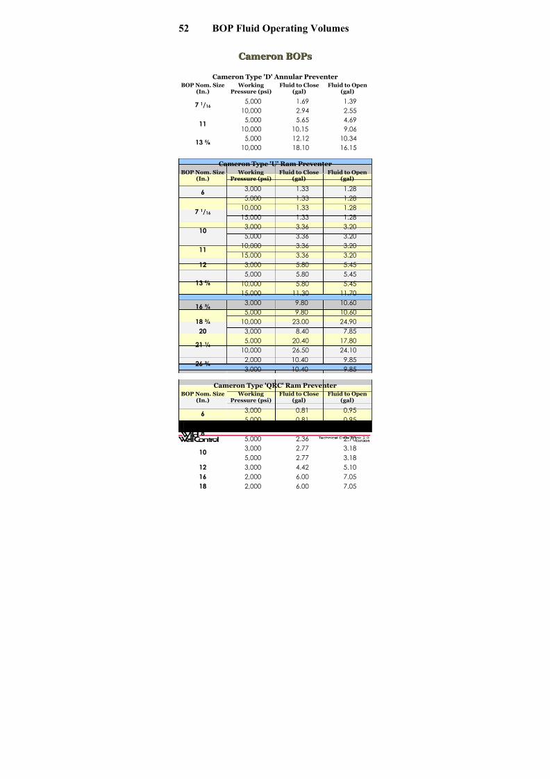
52 BOP Fluid Operating Volumes
CCaammeerroonn BBOOPPss
Cameron Type 'D' Annular PreventerBOP Nom. Size
(In.) Working
Pressure (psi)Fluid to Close
(gal)Fluid to Open
(gal)
5,000 1.69 1.397 1/16
10,000 2.94 2.555,000 5.65 4.69
1110,000 10.15 9.06
5,000 12.12 10.3413 ⅝
10,000 18.10 16.15
Cameron Type 'U' Ram Preventer
BOP Nom. Size(In.)
WorkingPressure (psi)
Fluid to Close(gal)
Fluid to Open(gal)
3,000 1.33 1.286
5,000 1.33 1.28
10,000 1.33 1.287 1/16
15,000 1.33 1.28
3,000 3.36 3.2010
5,000 3.36 3.20
10,000 3.36 3.2011
15,000 3.36 3.20
12 3,000 5.80 5.45
5,000 5.80 5.45
10,000 5.80 5.4513 ⅝
15,000 11.30 11.70
3,000 9.80 10.6016 ¾
5,000 9.80 10.60
18 ¾ 10,000 23.00 24.90
20 3,000 8.40 7.85
5,000 20.40 17.8021 ¼
10,000 26.50 24.10
2,000 10.40 9.8526 ¾
3,000 10.40 9.85
Cameron Type 'QRC' Ram Preventer
BOP Nom. Size(In.)
WorkingPressure (psi)
Fluid to Close(gal)
Fluid to Open(gal)
3,000 0.81 0.956
5,000 0.81 0.95
3,000 2.36 2.708
5,000 2.36 2.70
3,000 2.77 3.18105,000 2.77 3.18
12 3,000 4.42 5.10
16 2,000 6.00 7.05
18 2,000 6.00 7.05

8/15/2019 Technical Data Book - Well Control 2004
http://slidepdf.com/reader/full/technical-data-book-well-control-2004 54/66
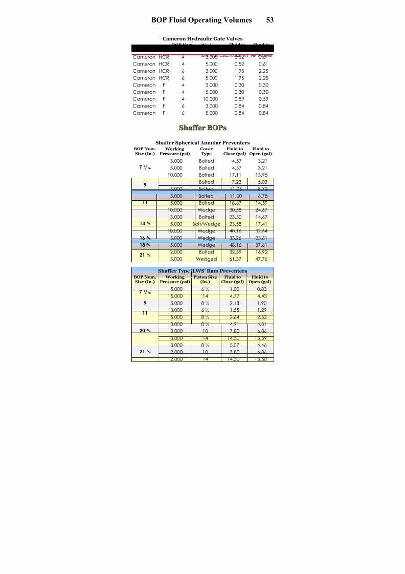
BOP Fluid Operating Volumes 53
5 3
Cameron Hydraulic Gate Valves OEM Type
BOP Nom.Size (In.)
WorkingPressure (psi)
Fluid toClose (gal)
Fluid toOpen (gal)
Cameron HCR 4 3,000 0.52 0.61
Cameron HCR 4 5,000 0.52 0.61
Cameron HCR 6 3,000 1.95 2.25
Cameron HCR 6 5,000 1.95 2.25
Cameron F 4 3,000 0.30 0.30
Cameron F 4 5,000 0.30 0.30
Cameron F 4 10,000 0.59 0.59
Cameron F 6 3,000 0.84 0.84
Cameron F 6 5,000 0.84 0.84
SShhaaf f f f eerr BBOOPPss
Shaffer Spherical Annular PreventersBOP Nom.Size (In.)
WorkingPressure (psi)
CoverType
Fluid toClose (gal)
Fluid toOpen (gal)
3,000 Bolted 4.57 3.21
5,000 Bolted 4.57 3.217 1/16
10,000 Bolted 17.11 13.95
3,000
Bolted 7.23 5.039
5,000 Bolted 11.05 8.72
3,000 Bolted 11.00 6.78
5,000 Bolted 18.67 14.5911
10,000 Wedge 30.58 24.67
3,000 Bolted 23.50 14.67
5,000 Bolt/Wedge 23.58 17.4113 ⅝
10,000 Wedge 40.16 32.64
16 ¾ 5,000 Wedge 33.26 25.61
18 ¾ 5,000 Wedge 48.16 37.612,000 Bolted 32.59 16.92
21 ¼5,000 Wedged 61.37 47.76
Shaffer Type 'LWS' Ram PreventersBOP Nom.Size (In.)
WorkingPressure (psi)
Piston Size(In.)
Fluid toClose (gal)
Fluid toOpen (gal)
5,000 6 ½ 1.00 0.837 1/16 15,000 14 4.77 4.43
9 5,000 8 ½ 2.18 1.90
3,000 6 ½ 1.55 1.2911
5,000 8 ½ 2.64 2.32
3,000 8 ½ 4.91 4.31
3,000 10 7.80 6.8620 ¾
3,000 14 14.50 13.59
3,000 8 ½ 5.07 4.46
2,000 10 7.80 6.8621 ¼
2,000 14 14.50 13.50
8/15/2019 Technical Data Book - Well Control 2004
http://slidepdf.com/reader/full/technical-data-book-well-control-2004 55/66
54 BOP Fluid Operating Volumes
Shaffer Type 'SL' Ram PreventersBOP Nom.Size (In.)
WorkingPressure (psi)
Piston Size(In.)
Fluid toClose (gal)
Fluid toOpen (gal)
15,000 10 2.72 2.347 1/16
15,000 14 6.00 5.57
10,000 14 9.45 7.0011
15,000 14 2.72 2.34
3,000 10 5.44 4.465,000 10 5.44 4.46
5,000 14 11.00 10.52
10,000 14 10.58 10.52
13 ⅝
15,000 14 11.56 10.52
5,000 10 11.76 5.44
5,000 14 10.67 4.4616 ¾10,000 14 14.47 12.5
18 ¾ 10,000 14 14.55 13.21
21 ¼ 10,000 14 16.05 13.86
Shaffer Hydraulic Gate Valves
OEM TypeBOP Nom.
Size (In.)
Working
Pressure (psi)
Fluid to
Close (gal)
Fluid to
Open (gal)Shaffer - 2 1/16 10,000 0.15 0.20
Shaffer - 3 1/16 5,000 0.20 0.25
Shaffer - 3 1/16 10,000 0.40 0.35
Shaffer - 3 1/16 15,000 0.35 0.40
Shaffer - 4 1/16 5,000 0.35 0.40
Shaffer - 4 1/16 10000 0.45 0.50
Shaffer - 4 1/16 15000 0.45 0.50
HH Y Y DDR R IILL BBOOPPss
Hydril Type 'GK' Annular PreventerBOP Nom.Size (In.)
Working Pressure(psi)
Fluid to Close(gal)
Fluid to Open(gal)
3,000 2.85 2.24
5,000 3.86 3.30
10,000 9.42 7.08
15,000 11.20 7.50
7 1/16
20,000 10.90 7.20
3,000 4.33 3.4195,000 6.84 5.80
3,000 7.43 5.54
5,000 9.81 7.97
10,000 25.10 18.8711
15,000 26.67 20.45
3,000 11.36 8.945,000 17.98 14.1513 ⅝
10,000 34.53 24.66
2,000 17.42 12.53
3,000 21.02 15.8016 ¾
5,000 28.70 19.93
8/15/2019 Technical Data Book - Well Control 2004
http://slidepdf.com/reader/full/technical-data-book-well-control-2004 56/66
BOP Fluid Operating Volumes 55
5 5
Hydril Type 'MSP' Annular PreventerBOP Nom.Size (In.)
Working Pressure(psi)
Fluid to Close(gal)
Fluid to Open(gal)
7 1/16 2,000 2.85 1.98
9 2,000 4.57 2.95
11 2,000 7.43 5.23
20 ¾ 2,000 31.05 18.93
21 ¼ 2,000 31.05 18.93
29 ½ 500 60.00 n/a
30 1,000 87.60 27.80
Hydril Type 'GL' Annular PreventerBOP Nom.
Size (In.)
Working
Pressure (psi)
Fluid to
Close (gal)
Fluid to
Open (gal)
Secondary
Fluid (gal)13 ⅝ 5,000 19.76 19.76 8.24
16 ¾ 5,000 33.80 33.80 17.30
18 ¾ 5,000 44.00 44.00 20.00
21 ¼ 5,000 58.00 58.00 29.50
Hydril Manual Lock Ram PreventersBOP Nom.Size (In.)
WorkingPressure (psi)
TypeFluid to
Close (gal)Fluid to
Open (gal)
3,000
V 1.30 1.20
5,000 V 1.30 1.20
10,000 X 1.90 1.807 1/16
15,000 X 3.70 3.40
3,000 V 1.90 1.909
5,000 V 1.90 1.90
3,000 V 3.10 3.10
5,000 V 3.10 3.1011
10,000 X 11.80 11.80
3,000 V 5.40 4.90
5,000 V 5.40 4.9013 ⅝
10,000 X 11.80 11.80
16 ¾ 10,000 X 15.00 14.10
18 ¾ 10,000 X 16.40 15.60
20 ¾ 3,000 V 8.10 7.20
21 ¼ 2,000 V 8.10 7.20

8/15/2019 Technical Data Book - Well Control 2004
http://slidepdf.com/reader/full/technical-data-book-well-control-2004 57/66

8/15/2019 Technical Data Book - Well Control 2004
http://slidepdf.com/reader/full/technical-data-book-well-control-2004 58/66

8/15/2019 Technical Data Book - Well Control 2004
http://slidepdf.com/reader/full/technical-data-book-well-control-2004 59/66
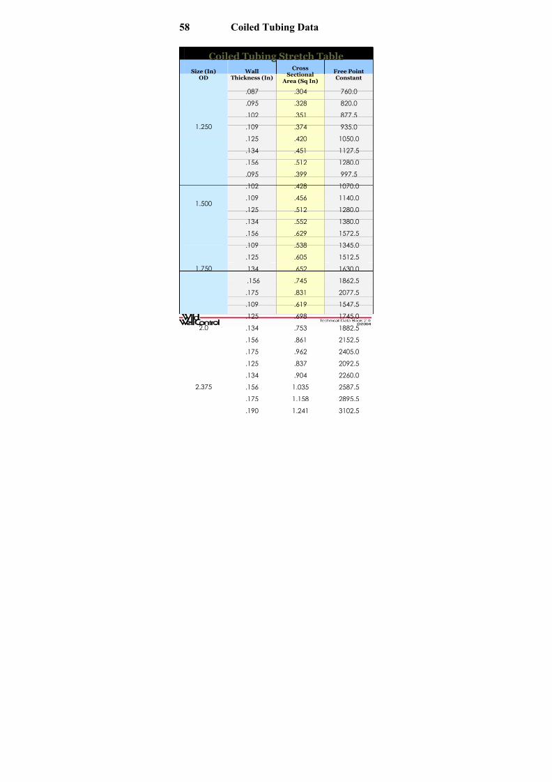
58 Coiled Tubing Data
CCooiilleedd TTuu b biinngg SSttrreettcchh TTaa b bllee
Size (In)OD
WallThickness (In)
CrossSectional
Area (Sq In)
Free PointConstant
.087 .304 760.0
.095 .328 820.0
.102 .351 877.5
.109 .374 935.0
.125 .420 1050.0
.134 .451 1127.5
1.250
.156 .512 1280.0
.095 .399 997.5
.102 .428 1070.0
.109 .456 1140.0
.125 .512 1280.0
.134 .552 1380.0
1.500
.156 .629 1572.5
.109 .538 1345.0
.125 .605 1512.5
.134 .652 1630.0
.156 .745 1862.5
1.750
.175 .831 2077.5
.109 .619 1547.5
.125 .698 1745.0
.134 .753 1882.5
.156 .861 2152.5
2.0
.175 .962 2405.0
.125 .837 2092.5
.134 .904 2260.0
.156 1.035 2587.5
.175 1.158 2895.5
2.375
.190 1.241 3102.5
8/15/2019 Technical Data Book - Well Control 2004
http://slidepdf.com/reader/full/technical-data-book-well-control-2004 60/66
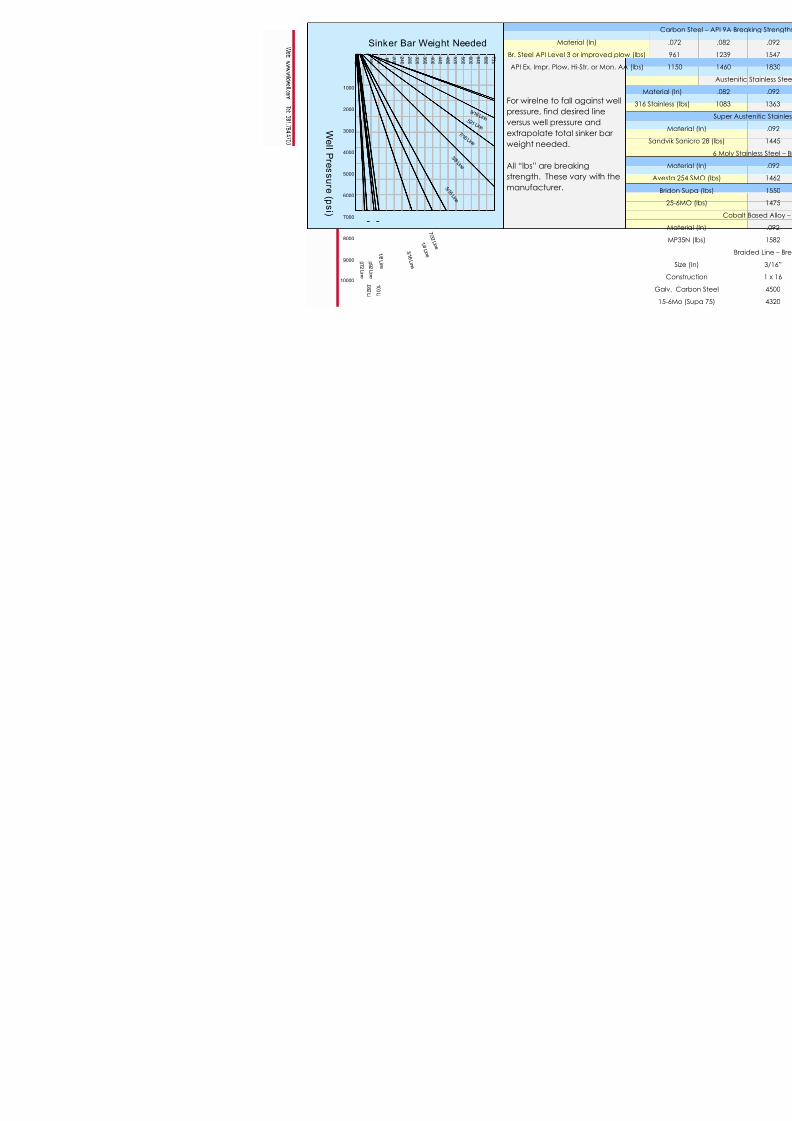
M
Br. Steel API Lev
API Ex. Impr. Plo
For wirelne to
pressure, find
versus well pr
extrapolate t
weight neede
All “lbs” are b
strength. The
manufacture
1000
2000
3000
4000
9000
10000
5000
6000
7000
80001 / 4
L i n e
9 / 1 6 Li n e .5 2 1 L i n e
7 / 1 6 L i n e
3 / 8 L i n e
5 / 1 6 L i n e
7 / 3
2 L i n e
3 / 1
6 L i n e
7 2 0
6 8 0
6 4 0
6 0 0
5 6 0
5 2 0
4 8 0
4 4 0
4 0 0
3 6 0
3 2 0
2 8 0
2 4 0
2 0 0
1 6 0
1 2 0
8 0
4 0 0
. 0 9 2
L i n e
. 0 8 2
L i
. 0 7 2
L i n e
1 / 8
L i n e
.1 0 0
L i
Sinker Bar Weight Needed
W el l P r e s s ur e ( p s i )
8/15/2019 Technical Data Book - Well Control 2004
http://slidepdf.com/reader/full/technical-data-book-well-control-2004 61/66
Cable Type Size (In.) Diameter (In.)Breaking
(lb
1-H-100-A 1/10 .101 1,0
1-H-125-A 1/8 .123 1,5
1-H-125-K 1/8 .123 1,5
1-H-181-A 3/16 .185 3,9
1-H-181-D 3/16 .185 3,9
1-H-181-K 3/16 .185 3,9
1-H-181-M 3/16 .187 3,6
4-H-181-A 3/16 .186 3,3
1-H-203-A 13/64 .203 4,5
1-H-203-D 13/64 .203 4,51-H-203-K 13/64 .203 4,5
1-H-220-A 7/32 .223 5,5
1-H-220-D 7/32 .223 5,5
1-H-220-K 7/32 .223 5,5
1-H-226-K 7/32 .222 5,0
1-H-281-A 9/32 .288 10,0
1-H-281-K 9/32 .288 10,0
1-H-314-A 5/16 .316 11,2
1-H-314-D 5/16 .316 11,2
1-H-314-K 5/16 .316 11,2
7-H-314-A 5/16 .323 9,6

8/15/2019 Technical Data Book - Well Control 2004
http://slidepdf.com/reader/full/technical-data-book-well-control-2004 62/66
Cable Type Size (In.) Diameter (In.)Breaking
(lb
1-H-375-A 3/8 .375 14,6
1-H-375-D 3/8 .375 14,6
1-H-375-K 3/8 .375 14,6
3-H-375-A 3/8 .372 13,5
4-H-375-A 3/8 .372 13,5
7-H-375-A 3/8 .372 12,8
1-H-422-A 7/16 .414 17,8
1-H-422-D 7/16 .414 17,8
1-H-422-K 7/16 .414 17,8
7-H-422-A 7/16 .426 18,37-H-422-D 7/16 .426 18,3
7-H-422-K 7/16 .426 18,3
7-H-464-A 15/32 .462 18,3
7-H-464-D 15/32 .462 18,3
7-H-464-K 15/32 .462 18,3
7-H-520-A 17/32 .522 26,0
7-H-520-D 17/32 .522 26,0
7-H-472-A Slammer .472 22,2
7-H-472-D Slammer .472 22,2
7-H-472-K Slammer .472 22,2

8/15/2019 Technical Data Book - Well Control 2004
http://slidepdf.com/reader/full/technical-data-book-well-control-2004 63/66
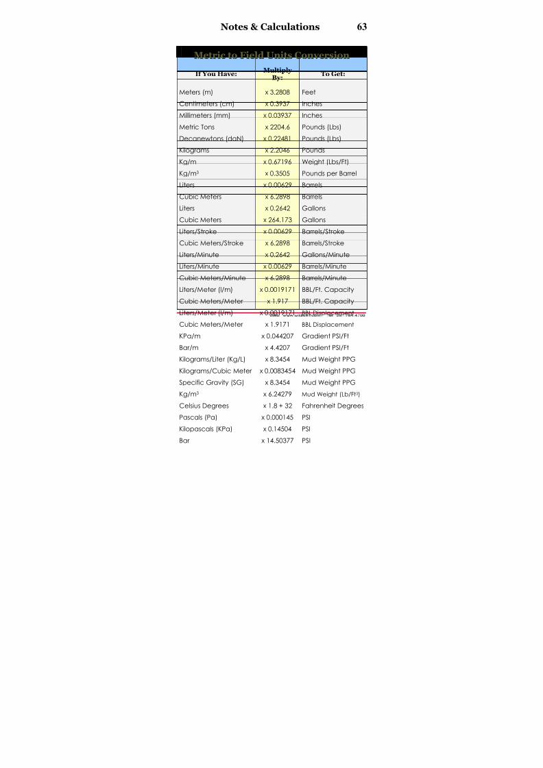
62 Conversion Factors
FFiieelldd UUnniittss ttoo MMeettrriicc CCoonn v v eerrssiioonn
If You Have:Multiply
By: To Get:
Feet x 0.3048 Meters (M)
Inches x 2.54 Centimeters (cm)
Inches x 25.4 Millimeters (mm)
Pounds (Lbs) x 0.0004536 Metric Tons
Pounds (Lbs) x 0.44482 Decanewtons (daN)
Pounds x 0.4536 Kilograms
Weight (Lbs/ft) x 1.4882 Kg/MPounds per Barrel x 2.85307 Kg/M3
Barrels x 158.987 Liters
Barrels x 0.15898 Cubic Meters
Gallons x 3.7854 Liters
Gallons x 0.0037854 Cubic Meters
Barrels/Stroke x 158.987 Liters/Stroke
Barrels/Stroke x 0.158987 Cubic Meters/Stroke
Gallons/Minute x 3.7854 Liters/Minute
Barrels/Minute x 158.987 Liters/Minute
Barrels/Minute x 0.158987 Cubic Meters/Minute
bbl/ft. Capacity x 521.612 Liters/Meter (L/M)
bbl/ft. Capacity x 0.521612 Cubic Meters/Meter
Bbl Displacement x 521.612 Liters/Meter (L/M)
Bbl Displacement x 0.521612 Cubic Meters/Meter
Gradient psi/ft x 22.6206 KPa/M
Gradient psi/ft x 0.226206 Bar/M
Mud Weight PPG x 0.119826 Kilograms/Liter (Kg/L)
Mud Weight PPG x 119.826 Kilograms/Cubic Meter
Mud Weight PPG x 0.119826 Specific Gravity (SG)Mud Weight (Lb/Ft3) x 1.60185 Kg/M3
Fahrenheit Degrees x 0.56 – 17.8 Celsius Degrees
PSI x 6894.8 Pascals (Pa)
PSI x 6.8948 Kilopascals (KPa)
PSI x 0.06895 Bar

8/15/2019 Technical Data Book - Well Control 2004
http://slidepdf.com/reader/full/technical-data-book-well-control-2004 64/66
Notes & Calculations 63
MMeettrriicc ttoo FFiieelldd UUnniittss CCoonn v v eerrssiioonn
If You Have:Multiply
By:To Get:
Meters (m) x 3.2808 Feet
Centimeters (cm) x 0.3937 Inches
Millimeters (mm) x 0.03937 Inches
Metric Tons x 2204.6 Pounds (Lbs)
Decanewtons (daN) x 0.22481 Pounds (Lbs)
Kilograms x 2.2046 Pounds
Kg/m x 0.67196 Weight (Lbs/Ft)Kg/m3 x 0.3505 Pounds per Barrel
Liters x 0.00629 Barrels
Cubic Meters x 6.2898 Barrels
Liters x 0.2642 Gallons
Cubic Meters x 264.173 Gallons
Liters/Stroke x 0.00629 Barrels/Stroke
Cubic Meters/Stroke x 6.2898 Barrels/Stroke
Liters/Minute x 0.2642 Gallons/Minute
Liters/Minute x 0.00629 Barrels/Minute
Cubic Meters/Minute x 6.2898 Barrels/Minute
Liters/Meter (l/m) x 0.0019171 BBL/Ft. Capacity
Cubic Meters/Meter x 1.917 BBL/Ft. Capacity
Liters/Meter (l/m) x 0.0019171 BBL Displacement
Cubic Meters/Meter x 1.9171 BBL Displacement
KPa/m x 0.044207 Gradient PSI/Ft
Bar/m x 4.4207 Gradient PSI/Ft
Kilograms/Liter (Kg/L) x 8.3454 Mud Weight PPG
Kilograms/Cubic Meter x 0.0083454 Mud Weight PPG
Specific Gravity (SG) x 8.3454 Mud Weight PPGKg/m3 x 6.24279 Mud Weight (Lb/Ft3)
Celsius Degrees x 1.8 + 32 Fahrenheit Degrees
Pascals (Pa) x 0.000145 PSI
Kilopascals (KPa) x 0.14504 PSI
Bar x 14.50377 PSI

8/15/2019 Technical Data Book - Well Control 2004
http://slidepdf.com/reader/full/technical-data-book-well-control-2004 65/66
64 Notes & Calculations

8/15/2019 Technical Data Book - Well Control 2004
http://slidepdf.com/reader/full/technical-data-book-well-control-2004 66/66
Well Control Emergency
First Response Checklist
• Evacuate all personnel
• Seek medical assistance if required
• Secure location
• Establish safety zone
• Initiate fire watch
• Implement emergency response plan
• Call drilling office
• Call Wild Well Control
281.784.4700
• Identify hazardous materials on site
• Monitor well conditions
• Stay in communication with Wild Well Control
2 8 1 . 7 8 4 . 4 7 0 0 ( U S A )