technical catalogue x1 by emax low voltage air ... - abb … · the x1 circuit-breaker by emax...
TRANSCRIPT
Technical catalogue X1 by Emax
Low voltage air circuit-breakers
1SDC200009D0202
X1
by
Em
ax
Lo
w v
olta
ge a
ir ci
rcui
t-br
eake
rs
Due to possible developments of standards as well as of materials, the characteristics and dimensions specified in the present catalogue may only be considered binding after confi rmation by ABB SACE. 1S
DC
2000
09D
0202
- 03
/200
7P
rinte
d in
Ital
y10
.000
- C
AL
ABB SACE S.p.A.An ABB Group company
L.V. BreakersVia Baioni, 3524123 Bergamo - ItalyTel.: +39 035.395.111 - Telefax: +39 035.395.306-433
http://www.abb.com
X1_copertina_new.indd 1X1_copertina_new.indd 1 6-04-2007 8:38:536-04-2007 8:38:53
X1_indice_new.indd 1X1_indice_new.indd 1 4-04-2007 10:22:184-04-2007 10:22:18

The X1 circuit-breaker by
Emax comes from more than 60
years' experience of ABB SACE, a world leader
in constructing moulded-case and air circuit-breakers. Our
know-how, appreciated and recognised world-wide, has allowed us to
obtain results which will amaze you. X1 by Emax is really small, powerful and
safe. In fact, the search for extremely compact dimensions has not in any way affected the
reliability and safety standards, because what counts most of all at ABB is the excellence of quality
of our products.
The new X1 by Emax is revolutionary from all points of view. For example, the new rapid accessory fitting
system: no wires inside the circuit-breaker, rapid and safe connection to the external circuit, and no screws for
connection to the external power supply.
Avanticatalogo_en_ok.indd 1Avanticatalogo_en_ok.indd 1 3-04-2007 16:56:283-04-2007 16:56:28
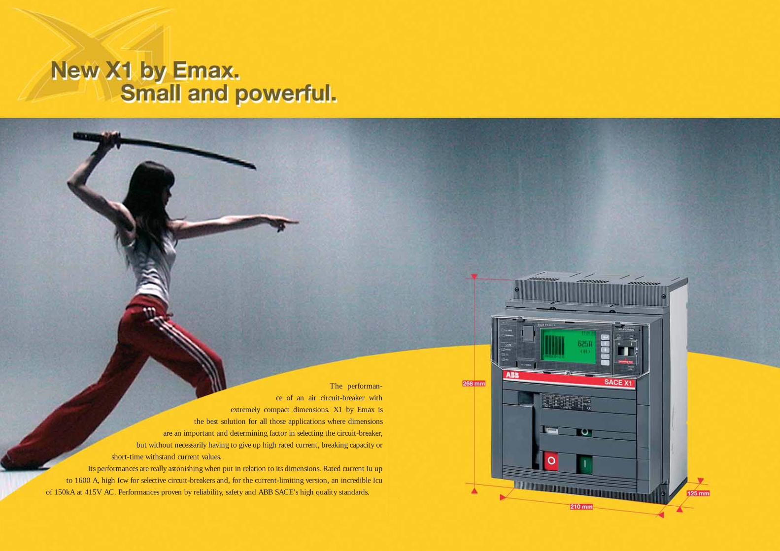
The performan-
ce of an air circuit-breaker with
extremely compact dimensions. X1 by Emax is
the best solution for all those applications where dimensions
are an important and determining factor in selecting the circuit-breaker,
but without necessarily having to give up high rated current, breaking capacity or
short-time withstand current values.
Its performances are really astonishing when put in relation to its dimensions. Rated current Iu up
to 1600 A, high Icw for selective circuit-breakers and, for the current-limiting version, an incredible Icu
of 150kA at 415V AC. Performances proven by reliability, safety and ABB SACE's high quality standards.
Avanticatalogo_en_ok.indd 2Avanticatalogo_en_ok.indd 2 3-04-2007 16:56:323-04-2007 16:56:32
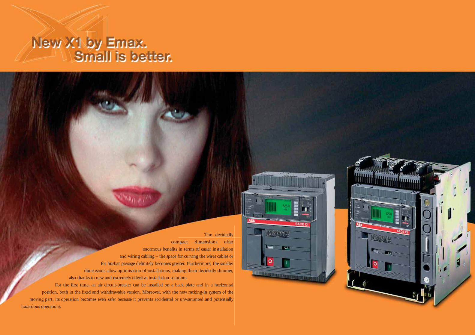
The decidedly
compact dimensions offer
enormous benefits in terms of easier installation
and wiring cabling – the space for curving the wires cables or
for busbar passage definitely becomes greater. Furthermore, the smaller
dimensions allow optimisation of installations, making them decidedly slimmer,
also thanks to new and extremely effective installation solutions.
For the first time, an air circuit-breaker can be installed on a back plate and in a horizontal
position, both in the fixed and withdrawable version. Moreover, with the new racking-in system of the
moving part, its operation becomes even safer because it prevents accidental or unwarranted and potentially
hazardous operations.
Avanticatalogo_en_ok.indd 3Avanticatalogo_en_ok.indd 3 3-04-2007 16:56:373-04-2007 16:56:37

X1 by Emax has
three brand-new latest generation
electronic trip units available: PR331/P, PR332/P
and PR333/P, which are definitely to the fore in the present
panorama of protection trip units for low voltage circuit-breakers. The basic
version, PR331/P, is fitted with dip-switches for setting the protection thresholds
and, for each protection function, has a LED for signalling that the protection has tripped.
On the other hand, PR332/P and PR333/P are fitted with a large graphic display which allows all the
information needed (settings of the protection functions, alarms and electrical values) to be displayed simply and
clearly. Apart from the “classic” protection functions, all three trip units offer advanced functions, such as the exclusive
Data Logger function, which allows all the events and values prior to a fault to be recorded for subsequent analysis.
Avanticatalogo_en_ok.indd 4Avanticatalogo_en_ok.indd 4 3-04-2007 16:56:443-04-2007 16:56:44
X1_cap_1_00.indd 2X1_cap_1_00.indd 2 6-04-2007 8:43:196-04-2007 8:43:19
1
ABB SACE 1/1
Main characteristics and ranges
ContentsOverview of the Emax family
Fields of application .............................................................................................................. 1/2
Emax X1 air circuit-breakers
The Ranges ......................................................................................................................... 1/4
Construction characteristics
Structure of the circuit-breaker ............................................................................................ 1/6
Operating mechanism .......................................................................................................... 1/7
Operating and signalling parts .............................................................................................. 1/8
Fixed parts of withdrawable circuit-breakers ........................................................................ 1/9
Utilization category ............................................................................................................... 1/10
Versions and connections ................................................................................................. 1/11
Electronic trip units
General characteristics ......................................................................................................... 1/12
Versions available ................................................................................................................ 1/14
Rating plugs ......................................................................................................................... 1/15
Compliance with Standards
Standards, approvals and certifi cations ............................................................................... 1/16
A design dedicated to Quality and respect for the environment .......................................... 1/17
X1_cap_1_00.indd 3X1_cap_1_00.indd 3 6-04-2007 8:43:246-04-2007 8:43:24
1
ABB SACE1/2
X1 E1 E2
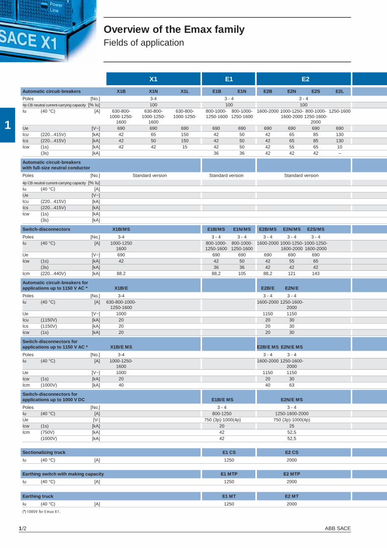
Overview of the Emax familyFields of application
(*) 1000V for Emax X1.
Automatic circuit-breakers X1B X1N X1L E1B E1N E2B E2N E2S E2L
Poles [No.] 3-4 3 - 4 3 - 4 4p CB neutral current-carrying capacity [% Iu] 100 100 100 Iu (40 °C) [A] 630-800- 630-800- 630-800- 800-1000- 800-1000- 1600-2000 1000-1250- 800-1000- 1250-1600 1000-1250- 1000-1250- 1000-1250- 1250-1600 1250-1600 1600-2000 1250-1600-
1600 1600 2000 Ue [V~] 690 690 690 690 690 690 690 690 690 Icu (220...415V) [kA] 42 65 150 42 50 42 65 85 130 Ics (220...415V) [kA] 42 50 150 42 50 42 65 85 130 Icw (1s) [kA] 42 42 15 42 50 42 55 65 10 (3s) [kA] 36 36 42 42 42 –
Automatic circuit-breakers with full-size neutral conductor
Poles [No.] Standard version Standard version Standard version
4p CB neutral current-carrying capacity [% Iu] Iu (40 °C) [A] Ue [V~] Icu (220...415V) [kA] Ics (220...415V) [kA] Icw (1s) [kA] (3s) [kA]
Switch-disconnectors X1B/MS E1B/MS E1N/MS E2B/MS E2N/MS E2S/MS
Poles [No.] 3-4 3 - 4 3 - 4 3 - 4 3 - 4 3 - 4 Iu (40 °C) [A] 1000-1250 800-1000- 800-1000- 1600-2000 1000-1250- 1000-1250- 1600 1250-1600 1250-1600 1600-2000 1600-2000 Ue [V~] 690 690 690 690 690 690 Icw (1s) [kA] 42 42 50 42 55 65 (3s) [kA] 36 36 42 42 42 Icm (220...440V) [kA] 88.2 88,2 105 88,2 121 143
Automatic circuit-breakers for applications up to 1150 V AC * X1B/E E2B/E E2N/E
Poles [No.] 3-4 3 - 4 3 - 4 Iu (40 °C) [A] 630-800-1000- 1600-2000 1250-1600- 1250-1600 2000 Ue [V~] 1000 1150 1150 Icu (1150V) [kA] 20 20 30 Ics (1150V) [kA] 20 20 30 Icw (1s) [kA] 20 20 30
Switch-disconnectors for applications up to 1150 V AC * X1B/E MS E2B/E MS E2N/E MS
Poles [No.] 3-4 3 - 4 3 - 4 Iu (40 °C) [A] 1000-1250- 1600-2000 1250-1600- 1600 2000 Ue [V~] 1000 1150 1150 Icw (1s) [kA] 20 20 30 Icm (1000V) [kA] 40 40 63
Switch-disconnectors for applications up to 1000 V DC E1B/E MS E2N/E MS
Poles [No.] 3 - 4 3 - 4 Iu (40 °C) [A] 800-1250 1250-1600-2000 Ue [V-] 750 (3p)-1000(4p) 750 (3p)-1000(4p) Icw (1s) [kA] 20 25 Icm (750V) [kA] 42 52,5 (1000V) [kA] 42 52,5
Sectionalizing truck E1 CS E2 CS
Iu (40 °C) [A] 1250 2000
Earthing switch with making capacity E1 MTP E2 MTP
Iu (40 °C) [A] 1250 2000
Earthing truck E1 MT E2 MT
Iu (40 °C) [A] 1250 2000
X1_cap_1_01.indd 2X1_cap_1_01.indd 2 3-04-2007 16:39:033-04-2007 16:39:03
1
ABB SACE 1/3
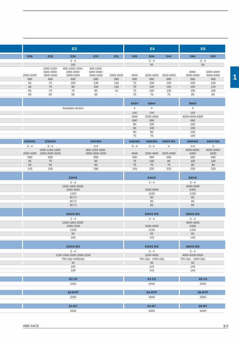
E3 E4 E6
E3N E3S E3H E3V E3L E4S E4H E4V E6H E6V
3 - 4 3 - 4 3 - 4 100 50 50 1000-1250- 800-1000-1250- 800-1250- 1600-2000- 1600-2000- 1600-2000- 4000- 3200-4000-
2500-3200 2500-3200 2500-3200 2500-3200 2000-2500 4000 3200-4000 3200-4000 5000-6300 5000-6300 690 690 690 690 690 690 690 690 690 69065 75 100 130 130 75 100 150 100 15065 75 85 100 130 75 100 150 100 125 65 75 75 85 15 75 100 100 100 100 65 65 65 65 – 75 75 75 85 85
E4S/f E4H/f E6H/f
Standard version 4 4 4
100 100 100 4000 3200-4000 4000-5000-6300 690 690 690 80 100 100 80 100 100 80 85 100 75 75 100
E3N/MS E3S/MS E3V/MS E4S/MS E4H/MS E4H/f MS E6H/MS E6H/f MS
3 - 4 3 - 4 3-4 3 - 4 3 - 4 4 3-4 4 1000-1250-1600- 800-1250-1600- 4000-5000- 4000-5000-
2500-3200 2000-2500-3200 2000-2500-3200 4000 3200-4000 3200-4000 6300 6300 690 690 690 690 690 690 690 690 65 75 85 75 100 85 100 100 65 65 65 75 75 75 85 85 143 165 286 165 220 220 220 220
E3H/E E4H/E E6H/E
3 - 4 3 - 4 3 - 4 1250-1600-2000- 4000-5000 2500-3200 3200-4000 6300 1150 1150 1150 30 (*) 65 65 30 (*) 65 65 30 (*) 65 65
E3H/E MS E4H/E MS E6H/E MS
3 - 4 3 - 4 3 - 4 1250-1600-2000- 4000-5000 2500-3200 3200-4000 6300 1150 1150 1150 50 65 65 105 143 143
E3H/E MS E4H/E MS E6H/E MS
3 - 4 3 - 4 3 - 4 1250-1600-2000-2500-3200 3200-4000 4000-5000-6300 750 (3p)-1000(4p) 750 (3p) - 1000 (4p) 750 (3p) - 1000 (4p) 40 65 65 105 143 143 105 143 143
E3 CS E4 CS E6 CS
3200 4000 6300
E3 MTP E4 MTP E6 MTP
3200 4000 6300
E3 MT E4 MT E6 MT
3200 4000 6300
X1_cap_1_01.indd 3X1_cap_1_01.indd 3 3-04-2007 16:39:053-04-2007 16:39:05
1
ABB SACE1/4
1SD
C20
0507
F000
1
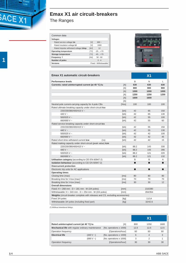
Common data
Voltages
Rated service voltage Ue [V] 690 ~
Rated insulation voltage Ui [V] 1000
Rated impulse withstand voltage Uimp [kV] 12
Operating temperature [°C] -25....+70
Storage temperature [°C] -40....+70
Frequency f [Hz] 50 - 60
Number of poles 3 - 4
Versions Fixed - Withdrawable
X1Performance levels B N L
Currents: rated uninterrupted current (at 40 °C) Iu [A] 630 630 630 [A] 800 800 800 [A] 1000 1000 1000 [A] 1250 1250 1250 [A] 1600 1600
[A]
Neutral pole current-carrying capacity for 4-pole CBs [%Iu] 100 100 100
Rated ultimate breaking capacity under short-circuit Icu
220/230/380/400/415 V ~ [kA] 42 65 150
440 V ~ [kA] 42 65 130
500/525 V ~ [kA] 42 55 100
660/690 V ~ [kA] 42 55 60
Rated service breaking capacity under short-circuit Ics
220/230/380/400/415 V ~ [kA] 42 55 150
440 V ~ [kA] 42 55 130
500/525 V ~ [kA] 42 42 100
660/690 V ~ [kA] 42 42 45
Rated short-time withstand current Icw (1s) [kA] 42 42 15
Rated making capacity under short-circuit (peak value) Icm
220/230/380/400/415 V ~ [kA] 88.2 143 330
440 V ~ [kA] 88.2 143 286
500/525 V ~ [kA] 88.2 121 220
660/690 V ~ [kA] 88.2 121 132
Utilisation category (according to CEI EN 60947-2) B B A
Isolation behaviour (according to CEI EN 60947-2) ■ ■ ■
Overcurrent protection
Electronic trip units for AC applications ■ ■ ■
Operating times
Closing time (max) [ms] 80 80 80
Breaking time for I<Icw (max) (1) [ms] 70 70 70
Breaking time for I>Icw (max) [ms] 30 30 12
Overall dimensions
Fixed: H = 268 mm - D = 181 mm - W (3/4 poles) [mm] 210/280
Withdrawable: H = 343 mm - D = 254 mm - W (3/4 poles) [mm] 284/354
Weights (circuit-breaker complete with releases and CS, excluding accessories)
Fixed 3/4 poles [kg] 11/14
Withdrawable 3/4 poles (including fi xed part) [kg] 32/42.6
(1) Without intentional delays.
Emax X1 air circuit-breakersThe Ranges
Emax X1 automatic circuit-breakers
X1Rated uninterrupted current (at 40 °C) Iu [A] 800 1250 1600
Mechanical life with regular ordinary maintenance [No. operations x 1000] 12,5 12,5 12,5
Operation frequency [Operations/hour] 60 60 60
Electrical life (440 V ~) [No. operations x 1000] 6 4 3
(690 V ~) [No. operations x 1000] 3 2 1
Operation frequency [Operations/hour] 30 30 30
X1_cap_1_01.indd 4X1_cap_1_01.indd 4 6-04-2007 8:45:126-04-2007 8:45:12
1
ABB SACE 1/5
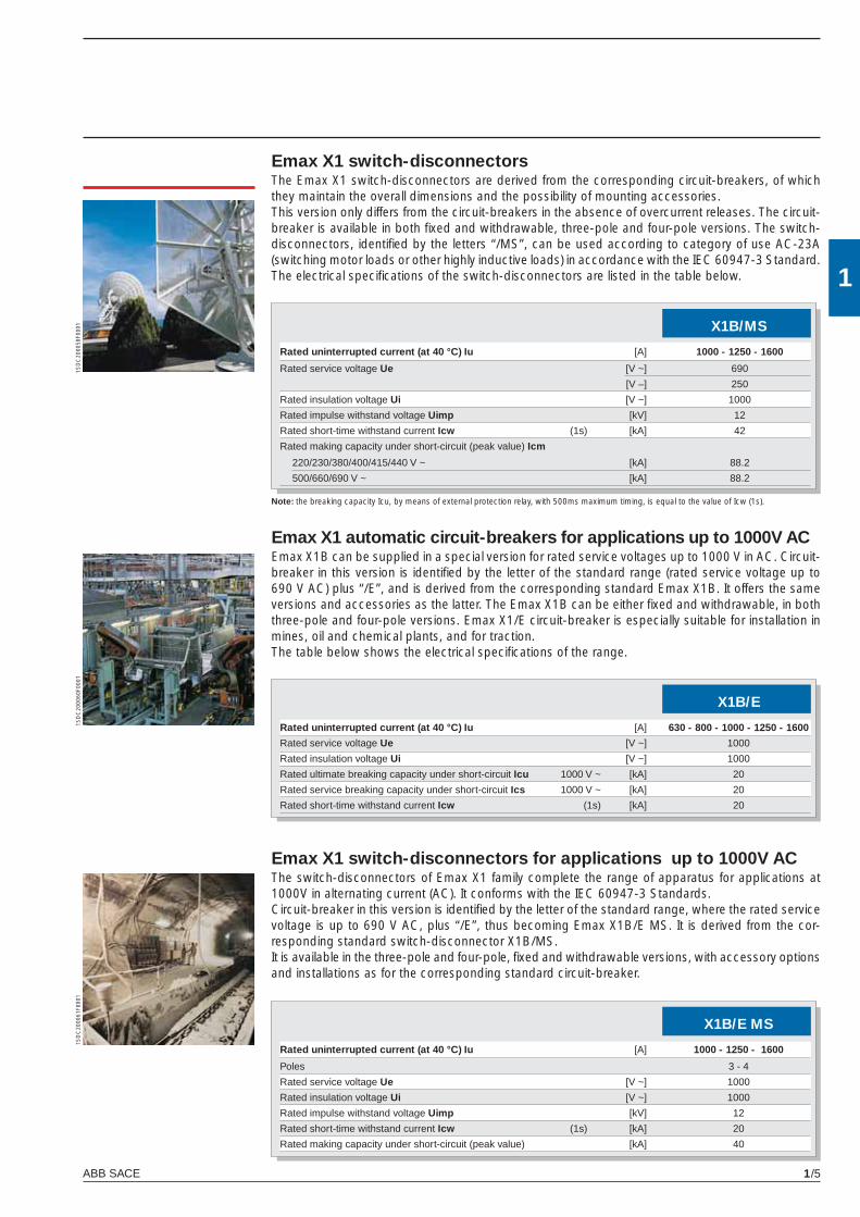
Emax X1 switch-disconnectorsThe Emax X1 switch-disconnectors are derived from the corresponding circuit-breakers, of which they maintain the overall dimensions and the possibility of mounting accessories.This version only differs from the circuit-breakers in the absence of overcurrent releases. The circuit-breaker is available in both fi xed and withdrawable, three-pole and four-pole versions. The switch-disconnectors, identifi ed by the letters “/MS”, can be used according to category of use AC-23A (switching motor loads or other highly inductive loads) in accordance with the IEC 60947-3 Standard. The electrical specifi cations of the switch-disconnectors are listed in the table below.
Emax X1 automatic circuit-breakers for applications up to 1000V ACEmax X1B can be supplied in a special version for rated service voltages up to 1000 V in AC. Circuit-breaker in this version is identifi ed by the letter of the standard range (rated service voltage up to 690 V AC) plus “/E”, and is derived from the corresponding standard Emax X1B. It offers the same versions and accessories as the latter. The Emax X1B can be either fi xed and withdrawable, in both three-pole and four-pole versions. Emax X1/E circuit-breaker is especially suitable for installation in mines, oil and chemical plants, and for traction.The table below shows the electrical specifi cations of the range.
Emax X1 switch-disconnectors for applications up to 1000V ACThe switch-disconnectors of Emax X1 family complete the range of apparatus for applications at 1000V in alternating current (AC). It conforms with the IEC 60947-3 Standards.Circuit-breaker in this version is identifi ed by the letter of the standard range, where the rated service voltage is up to 690 V AC, plus “/E”, thus becoming Emax X1B/E MS. It is derived from the cor-responding standard switch-disconnector X1B/MS.It is available in the three-pole and four-pole, fi xed and withdrawable versions, with accessory options and installations as for the corresponding standard circuit-breaker.
1SD
C20
0058
F000
11S
DC
2000
60F0
001
1SD
C20
0061
F000
1
X1B/MS
Rated uninterrupted current (at 40 °C) Iu [A] 1000 - 1250 - 1600
Rated service voltage Ue [V ~] 690
[V –] 250
Rated insulation voltage Ui [V ~] 1000
Rated impulse withstand voltage Uimp [kV] 12
Rated short-time withstand current Icw (1s) [kA] 42
Rated making capacity under short-circuit (peak value) Icm
220/230/380/400/415/440 V ~ [kA] 88.2
500/660/690 V ~ [kA] 88.2
Note: the breaking capacity Icu, by means of external protection relay, with 500ms maximum timing, is equal to the value of Icw (1s).
X1B/E
Rated uninterrupted current (at 40 °C) Iu [A] 630 - 800 - 1000 - 1250 - 1600
Rated service voltage Ue [V ~] 1000
Rated insulation voltage Ui [V ~] 1000
Rated ultimate breaking capacity under short-circuit Icu 1000 V ~ [kA] 20
Rated service breaking capacity under short-circuit Ics 1000 V ~ [kA] 20
Rated short-time withstand current Icw (1s) [kA] 20
X1B/E MS
Rated uninterrupted current (at 40 °C) Iu [A] 1000 - 1250 - 1600
Poles 3 - 4
Rated service voltage Ue [V ~] 1000
Rated insulation voltage Ui [V ~] 1000
Rated impulse withstand voltage Uimp [kV] 12
Rated short-time withstand current Icw (1s) [kA] 20
Rated making capacity under short-circuit (peak value) [kA] 40
X1_cap_1_01.indd 5X1_cap_1_01.indd 5 3-04-2007 16:39:073-04-2007 16:39:07
1
ABB SACE1/6
1SD
C20
0508
F000
1
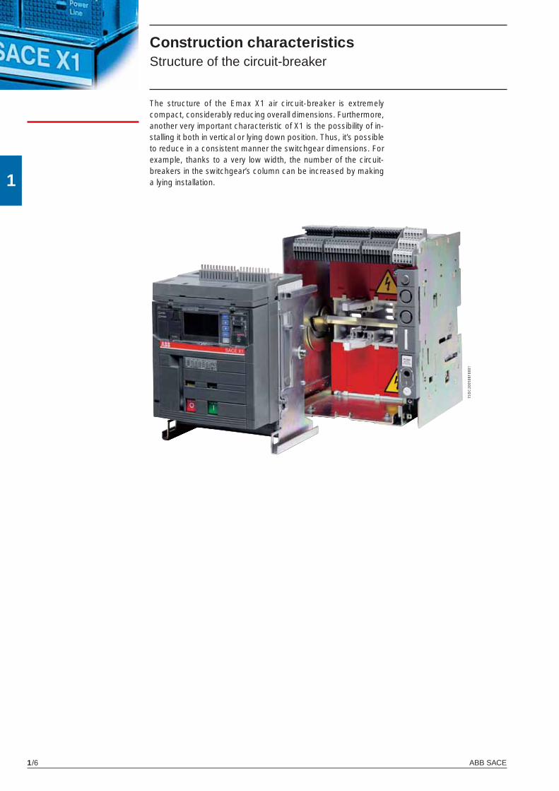
Construction characteristicsStructure of the circuit-breaker
The structure of the Emax X1 air circuit-breaker is extremely compact, considerably reducing overall dimensions. Furthermore, another very important characteristic of X1 is the possibility of in-stalling it both in vertical or lying down position. Thus, it’s possible to reduce in a consistent manner the switchgear dimensions. For example, thanks to a very low width, the number of the circuit-breakers in the switchgear’s column can be increased by making a lying installation.
X1_cap_1_01.indd 6X1_cap_1_01.indd 6 3-04-2007 16:39:083-04-2007 16:39:08

1
ABB SACE 1/7
1SD
C20
0509
F000
1
1SD
C20
0510
F000
1
Construction characteristicsOperating mechanism
The operating mechanism is of the stored energy type, operated using pre-charged springs.The springs are charged manually by operating the front lever or using a geared motor, supplied on request.The opening springs are charged automatically during the closing operation.With the operating mechanism fi tted with shunt closing and open-ing releases and the geared motor for charging the springs, the circuit-breaker can be operated by remote control and, if required, co-ordinated by a supervision and control system.
➀ CLOSING
➁ OPENING➀ OPENING
➂ OPENING
The following operating cycles are possible without recharging the springs:– starting with the circuit-breaker open (0) and the springs
charged: closing-opening– starting with the circuit-breaker closed (I) and the springs
charged: opening-closing-opening.
The operating mechanism is fi tted with a mechanical and electrical anti-pumping device.
➁ CLOSING
X1_cap_1_01.indd 7X1_cap_1_01.indd 7 3-04-2007 16:39:103-04-2007 16:39:10
1
ABB SACE1/8
6
4
5
3
1
8
11
7
2
9
2
4
6
7
12
5
3
1
8
9
13
10
1SD
C20
0507
F000
1
1SD
C20
0511
F000
1
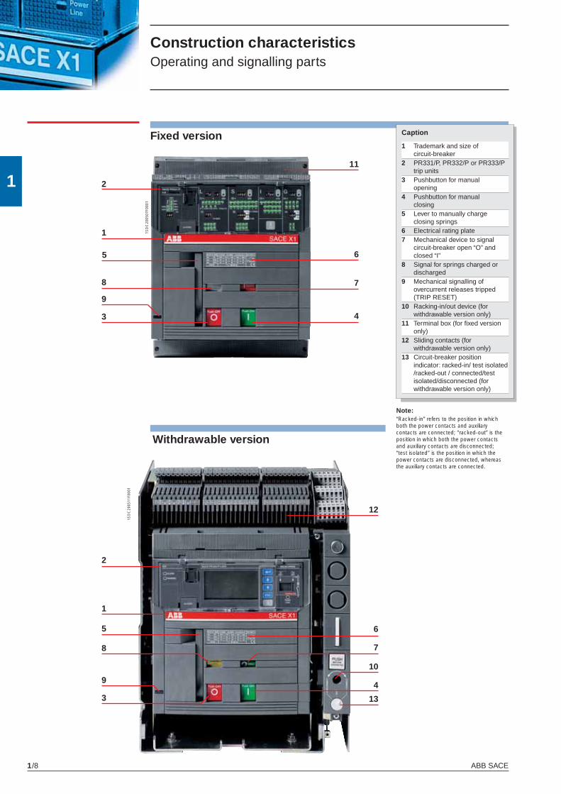
Construction characteristicsOperating and signalling parts
Fixed version
Note: “Racked-in” refers to the position in whichboth the power contacts and auxiliarycontacts are connected; “racked-out” is theposition in which both the power contactsand auxiliary contacts are disconnected;“test isolated” is the position in which thepower contacts are disconnected, whereasthe auxiliary contacts are connected.
Withdrawable version
Caption
1 Trademark and size of circuit-breaker
2 PR331/P, PR332/P or PR333/P trip units
3 Pushbutton for manual opening4 Pushbutton for manual closing5 Lever to manually charge
closing springs6 Electrical rating plate7 Mechanical device to signal
circuit-breaker open “O” and closed “I”
8 Signal for springs charged or discharged
9 Mechanical signalling of overcurrent releases tripped (TRIP RESET)
10 Racking-in/out device (for withdrawable version only)
11 Terminal box (for fi xed version only)
12 Sliding contacts (for withdrawable version only)
13 Circuit-breaker position indicator: racked-in/ test isolated /racked-out / connected/test isolated/disconnected (for withdrawable version only)
X1_cap_1_01.indd 8X1_cap_1_01.indd 8 3-04-2007 16:39:113-04-2007 16:39:11
1
ABB SACE 1/9
1
4
5
2
3
6
1SD
C20
0512
F000
1
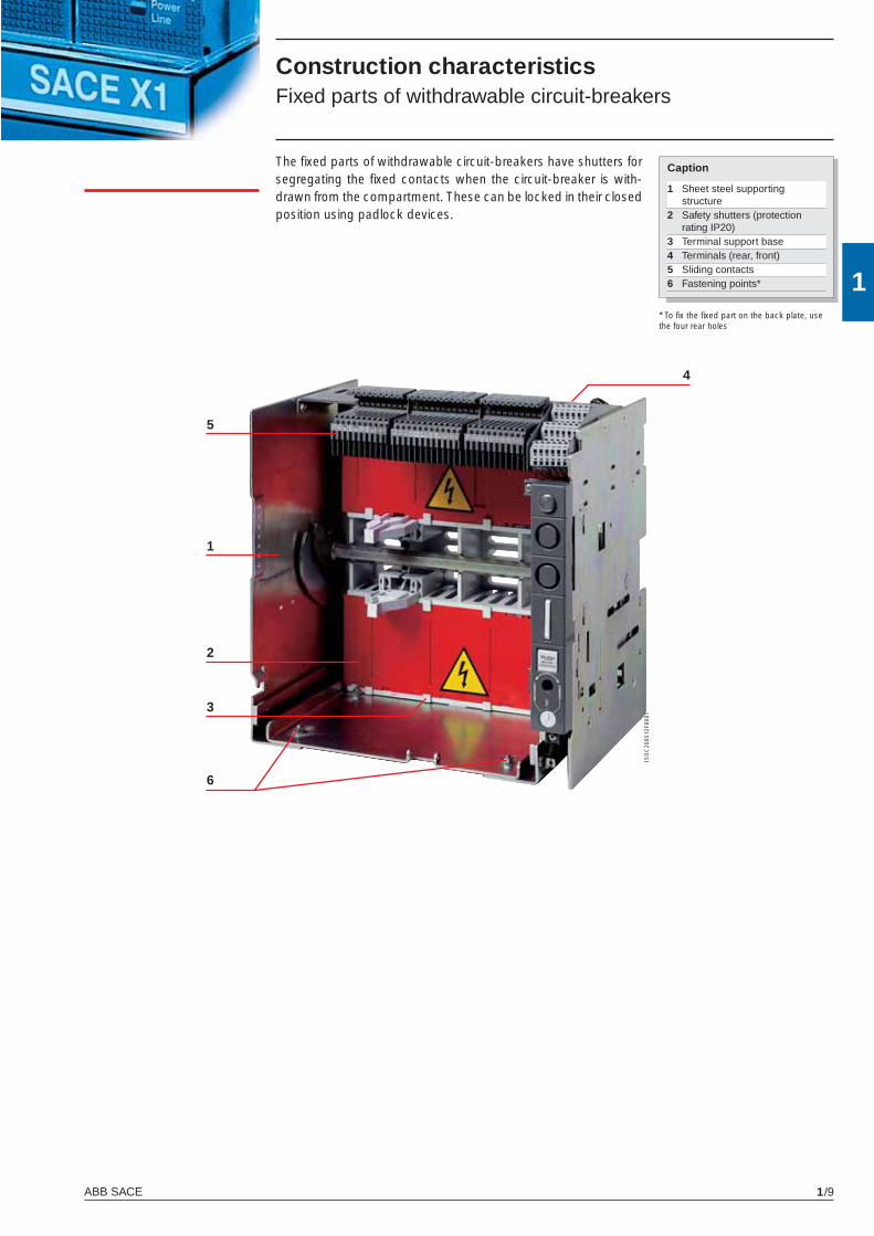
The fi xed parts of withdrawable circuit-breakers have shutters for segregating the fi xed contacts when the circuit-breaker is with-drawn from the compartment. These can be locked in their closed position using padlock devices.
Construction characteristicsFixed parts of withdrawable circuit-breakers
* To fi x the fi xed part on the back plate, use the four rear holes
Caption
1 Sheet steel supporting structure
2 Safety shutters (protection rating IP20)
3 Terminal support base4 Terminals (rear, front)5 Sliding contacts6 Fastening points*
X1_cap_1_01.indd 9X1_cap_1_01.indd 9 3-04-2007 16:39:133-04-2007 16:39:13
1
ABB SACE1/10
Construction characteristicsUtilization category
Selective and current-limiting circuit-breakers Selective (not current-limiting) circuit-breakers are classifi ed in class B (according to the IEC 60947-2 Standard). It is important to know their Icw values in relation to any possible delayed trips in the event of short-circuits.
The current-limiting circuit-breaker X1L belongs to class A. The short-time withstand current Icw is not very important for this circuit-breaker, and is necessarily low due to the operating principle on which it is based. The fact that it belongs to class A does not preclude the possibility of obtaining the necessary selectivity (e.g. current-type or time-type selectivity).The special advantages of current-limiting circuit-breakers should also be underlined. In fact, they make it possible to:– signifi cantly reduce the peak current in relation to the prospective
value;– drastically limit specifi c let-through energy.
The resulting benefi ts include:
– reduced electrodynamic stresses;– reduced thermal stresses;– savings on the sizing of cables and busbars;– the possibility of coordinating with other circuit-breakers in the
series for back-up or discrimination.
X1_cap_1_01.indd 10X1_cap_1_01.indd 10 3-04-2007 16:39:153-04-2007 16:39:15
1
ABB SACE 1/11
Fixed circuit-breaker
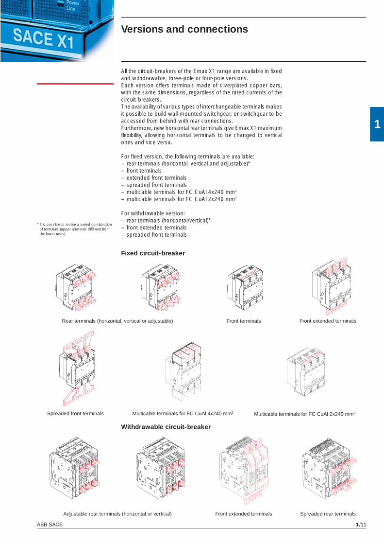
All the circuit-breakers of the Emax X1 range are available in fi xed and withdrawable, three-pole or four-pole versions.Each version offers terminals made of silverplated copper bars, with the same dimensions, regardless of the rated currents of the circuit-breakers.The availability of various types of interchangeable terminals makes it possible to build wall-mounted switchgear, or switchgear to be accessed from behind with rear connections.Furthermore, new horizontal rear terminals give Emax X1 maximum fl exibility, allowing horizontal terminals to be changed to vertical ones and vice versa.
For fi xed version, the following terminals are available:– rear terminals (horizontal, vertical and adjustable)*– front terminals– extended front terminals– spreaded front terminals– multicable terminals for FC CuAl 4x240 mm2
– multicable terminals for FC CuAl 2x240 mm2
For withdrawable version:– rear terminals (horizontal/vertical)*– front extended terminals– spreaded front terminals
Withdrawable circuit-breaker
Rear terminals (horizontal, vertical or adjustable) Front terminals
Adjustable rear terminals (horizontal or vertical) Front extended terminals
Versions and connections
* It is possible to realise a varied combination of terminals (upper terminals different from the lower ones)
Multicable terminals for FC CuAl 4x240 mm2Spreaded front terminals
Front extended terminals
Multicable terminals for FC CuAl 2x240 mm2
Spreaded rear terminals
X1_cap_1_01.indd 11X1_cap_1_01.indd 11 3-04-2007 16:39:153-04-2007 16:39:15
1
ABB SACE1/12
Electronic trip unitsGeneral characteristics
The overcurrent protection for AC installations uses three types of electronic trip unit series: PR331/P, PR332/P and PR333/P.The basic series, PR331/P, offers the whole set of standard pro-tection functions, complete with a user-friendly interface. It allows discrimination of which fault caused the trip by means of the new led indications.PR332/P and PR333/P trip units are of new concept modular archi-tecture. It is now possible to have a complete series of protections, accurate measurements, signalling or dialogue functions, designed and customisable for all application requirements.The protection system is made up of:• 3 or 4 new generation current sensors (Rogowsky coil);• external current sensors (i.e. for external neutral, residual current
or source ground return protection);• a protection unit selected among PR331/P, PR332/P or PR333/P
with optional communication module via Modbus or Fieldbus plug network (PR332/P and PR333/P only), as well as via a wireless connection;
• a trip coil, which acts directly on the circuit-breaker operating mechanism (supplied with the protection unit).
X1_cap_1_01.indd 12X1_cap_1_01.indd 12 3-04-2007 16:39:163-04-2007 16:39:16
1
ABB SACE 1/13
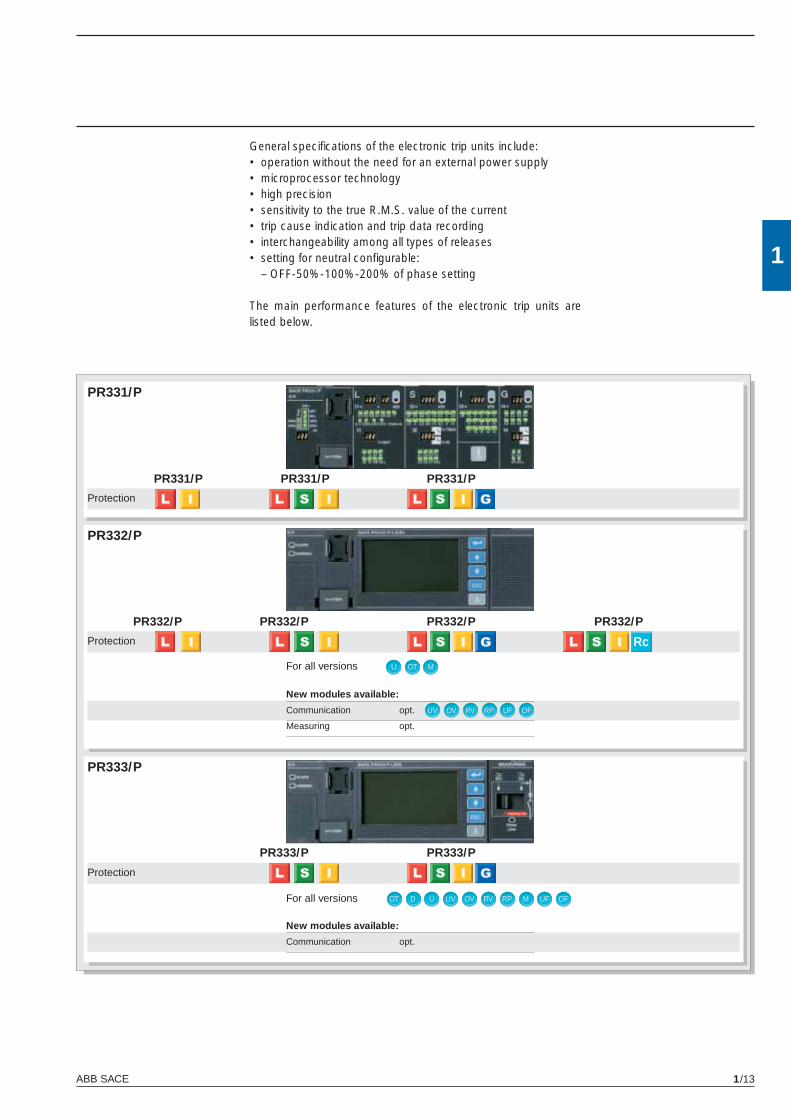
PR331/P
PR331/P PR331/P PR331/P
PR332/P
PR332/P PR332/PPR332/P PR332/P
Rc
OT MU
OV RV RP UF OFUV
PR333/P
OT D U UV OV RV RP M UF OF
PR333/P PR333/P
General specifi cations of the electronic trip units include:• operation without the need for an external power supply• microprocessor technology• high precision• sensitivity to the true R.M.S. value of the current• trip cause indication and trip data recording• interchangeability among all types of releases• setting for neutral confi gurable: – OFF-50%-100%-200% of phase setting
The main performance features of the electronic trip units are listed below.
New modules available:
Communication opt.
Measuring opt.
Protection
Protection
For all versions
Protection
New modules available:
Communication opt.
For all versions
X1_cap_1_01.indd 13X1_cap_1_01.indd 13 3-04-2007 16:39:173-04-2007 16:39:17
1
ABB SACE1/14
PR333/PPR332/PPR331/P
Rc
U
OT
UV
OV
RV
RP
MCR
M
UF
OF
D
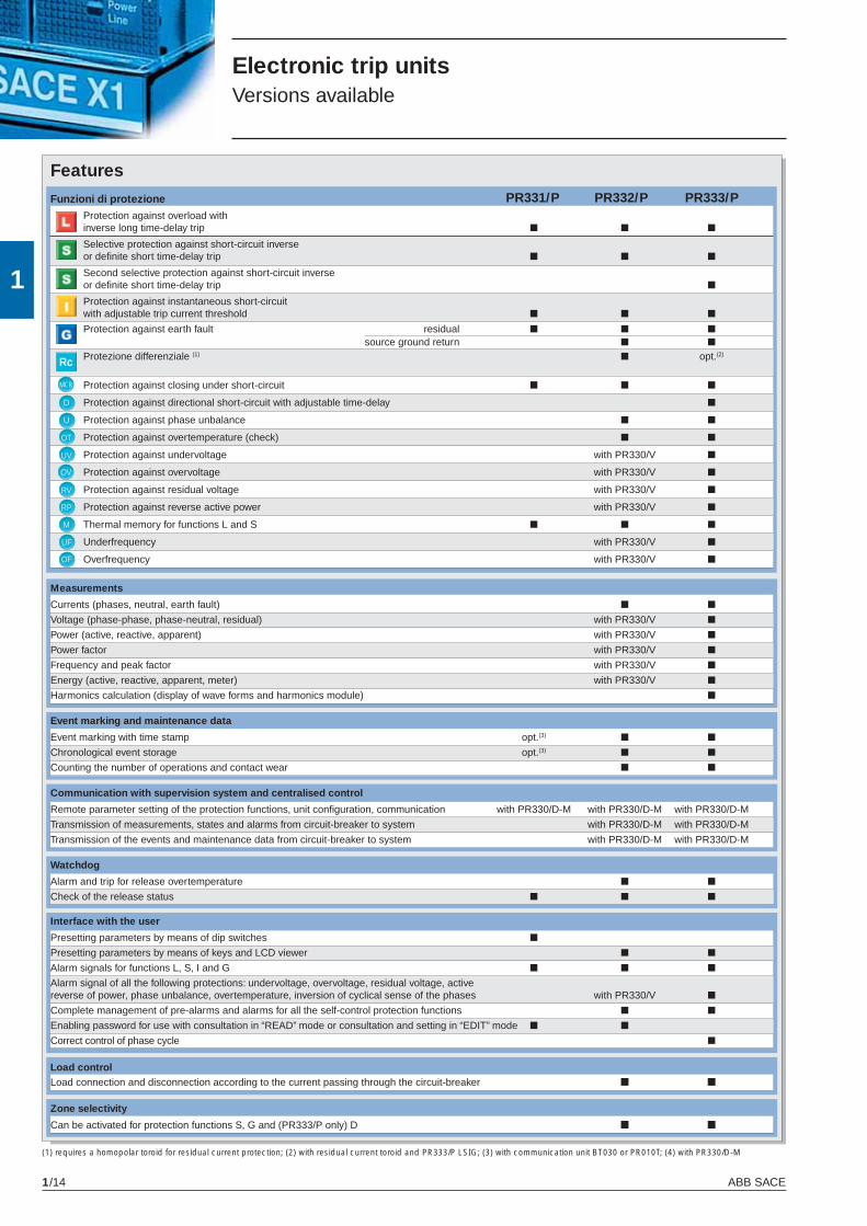
Features
Electronic trip unitsVersions available
(1) requires a homopolar toroid for residual current protection; (2) with residual current toroid and PR333/P LSIG; (3) with communication unit BT030 or PR010T; (4) with PR330/D-M
Funzioni di protezione
Protection against overload with inverse long time-delay trip ■ ■ ■
Selective protection against short-circuit inverse or defi nite short time-delay trip ■ ■ ■
Second selective protection against short-circuit inverse or defi nite short time-delay trip ■
Protection against instantaneous short-circuit with adjustable trip current threshold ■ ■ ■
Protection against earth fault residual ■ ■ ■ source ground return ■ ■ Protezione differenziale (1) ■ opt.(2)
Protection against closing under short-circuit ■ ■ ■
Protection against directional short-circuit with adjustable time-delay ■
Protection against phase unbalance ■ ■
Protection against overtemperature (check) ■ ■
Protection against undervoltage with PR330/V ■
Protection against overvoltage with PR330/V ■
Protection against residual voltage with PR330/V ■
Protection against reverse active power with PR330/V ■
Thermal memory for functions L and S ■ ■ ■
Underfrequency with PR330/V ■
Overfrequency with PR330/V ■
Measurements
Currents (phases, neutral, earth fault) ■ ■
Voltage (phase-phase, phase-neutral, residual) with PR330/V ■
Power (active, reactive, apparent) with PR330/V ■
Power factor with PR330/V ■
Frequency and peak factor with PR330/V ■
Energy (active, reactive, apparent, meter) with PR330/V ■
Harmonics calculation (display of wave forms and harmonics module) ■
Event marking and maintenance data
Event marking with time stamp opt.(3) ■ ■
Chronological event storage opt.(3) ■ ■
Counting the number of operations and contact wear ■ ■
Communication with supervision system and centralised control
Remote parameter setting of the protection functions, unit confi guration, communication with PR330/D-M with PR330/D-M with PR330/D-M
Transmission of measurements, states and alarms from circuit-breaker to system with PR330/D-M with PR330/D-M
Transmission of the events and maintenance data from circuit-breaker to system with PR330/D-M with PR330/D-M
Watchdog
Alarm and trip for release overtemperature ■ ■
Check of the release status ■ ■ ■
Interface with the user
Presetting parameters by means of dip switches ■
Presetting parameters by means of keys and LCD viewer ■ ■
Alarm signals for functions L, S, I and G ■ ■ ■
Alarm signal of all the following protections: undervoltage, overvoltage, residual voltage, active reverse of power, phase unbalance, overtemperature, inversion of cyclical sense of the phases with PR330/V ■
Complete management of pre-alarms and alarms for all the self-control protection functions ■ ■
Enabling password for use with consultation in “READ” mode or consultation and setting in “EDIT” mode ■ ■
Correct control of phase cycle ■
Load control Load connection and disconnection according to the current passing through the circuit-breaker ■ ■
Zone selectivity
Can be activated for protection functions S, G and (PR333/P only) D ■ ■
X1_cap_1_01.indd 14X1_cap_1_01.indd 14 6-04-2007 8:49:086-04-2007 8:49:08
1
ABB SACE 1/15
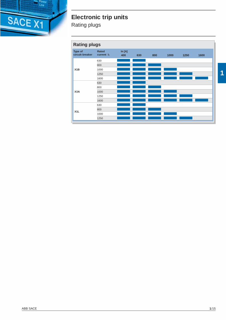
In [A] 400 630 800 1000 1250 1600
630
800
X1B 1000
1250 1600
630
800
X1N 1000
1250 1600
630
800
X1L
1000
1250
Type of Rated circuit-breaker current Iu
Rating plugs
Electronic trip unitsRating plugs
X1_cap_1_01.indd 15X1_cap_1_01.indd 15 3-04-2007 16:39:263-04-2007 16:39:26

1
ABB SACE1/16
1
Compliance with StandardsStandards, approvals and certifi cations
Emax X1 and their accessories conform to the international IEC 60947, EN 60947 (harmonized in 28 CENELEC countries), CEI EN 60947 and IEC 61000 Standards, and comply with following EC directives:– “Low Voltage Directives” (LVD) no. 2006/95/CE ( replaces 72/23/
EEC and subsequent amendments).– “Electromagnetic Compatibility Directive” (EMC) nr. 89/336
EEC.
The following Shipping Registers certifi cations are being ap-proved:
– RINA (Italian Naval Register)– Det Norske Veritas– Bureau Veritas– Germanischer Lloyd– Loyd’s Register of Shipping– Polskj Rejestr Statkow– ABS (American Bureau of Shipping)– RMRS (Russian Maritime Register of Shipping)– NK (Nippon Kaiji Kyokai)
The Emax X1 has also a range which is under certifi cation ac-cording to the severe American UL 1066 and UL 489 Standards, the Russian GOST (Russia Certifi cate of Conformity) certifi cation organization, and CCC (China Compulsory Certifi cation).
Certifi cation of conformity with the aforementioned product Stan-dards is carried out in compliance with European Standard EN 45011 by the Italian certifi cation body ACAE (Associazione per la Certifi cazione delle Apparecchiature Elettriche - Association for Certifi cation of Electrical Apparatus), recognized by the European organization LOVAG (Low Voltage Agreement Group).
Note: Contact ABB SACE for a list of ap-proved types of circuit-breakers, approved performance data and the corresponding validity
X1_cap_1_01.indd 16X1_cap_1_01.indd 16 3-04-2007 16:39:273-04-2007 16:39:27
1
ABB SACE 1/17
1
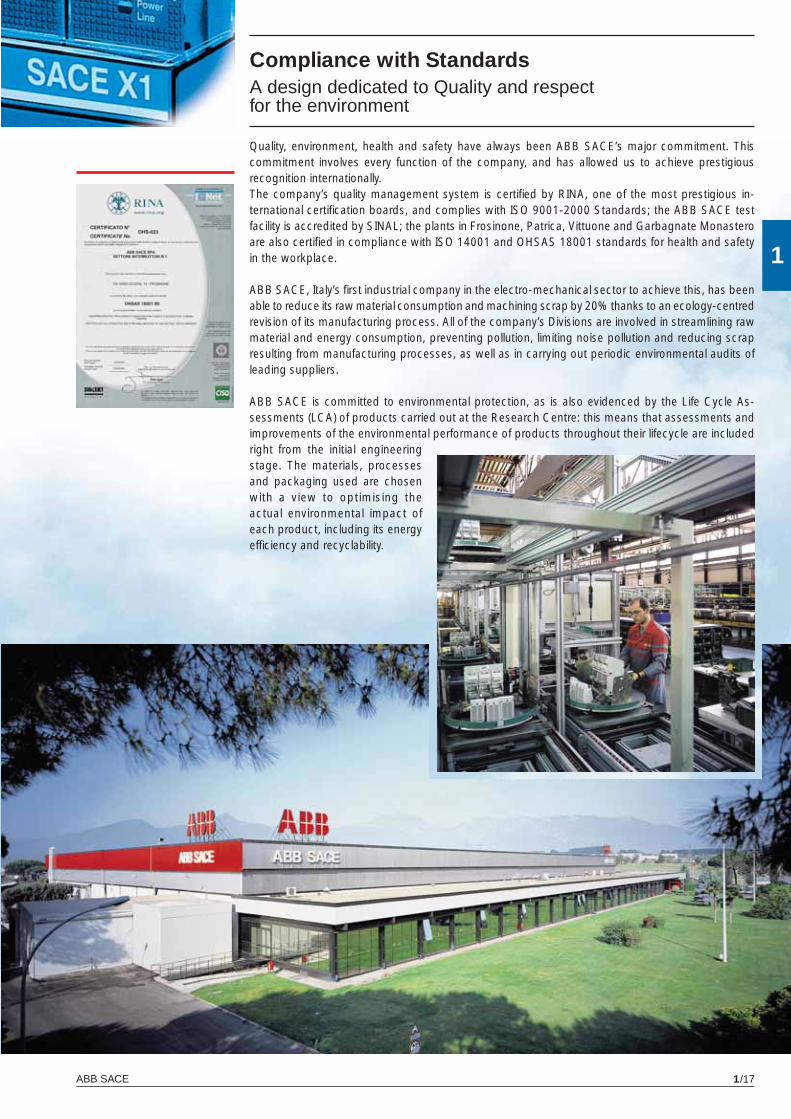
Compliance with StandardsA design dedicated to Quality and respect for the environment
Quality, environment, health and safety have always been ABB SACE’s major commitment. This commitment involves every function of the company, and has allowed us to achieve prestigious recognition internationally.The company’s quality management system is certifi ed by RINA, one of the most prestigious in-ternational certifi cation boards, and complies with ISO 9001-2000 Standards; the ABB SACE test facility is accredited by SINAL; the plants in Frosinone, Patrica, Vittuone and Garbagnate Monastero are also certifi ed in compliance with ISO 14001 and OHSAS 18001 standards for health and safety in the workplace.
ABB SACE, Italy’s fi rst industrial company in the electro-mechanical sector to achieve this, has been able to reduce its raw material consumption and machining scrap by 20% thanks to an ecology-centred revision of its manufacturing process. All of the company’s Divisions are involved in streamlining raw material and energy consumption, preventing pollution, limiting noise pollution and reducing scrap resulting from manufacturing processes, as well as in carrying out periodic environmental audits of leading suppliers.
ABB SACE is committed to environmental protection, as is also evidenced by the Life Cycle As-sessments (LCA) of products carried out at the Research Centre: this means that assessments and improvements of the environmental performance of products throughout their lifecycle are included right from the initial engineering stage. The materials, processes and packaging used are chosen with a view to optimising the actual environmental impact of each product, including its energy effi ciency and recyclability.
X1_cap_1_01.indd 17X1_cap_1_01.indd 17 3-04-2007 16:39:373-04-2007 16:39:37
X1_cap_2_00.indd 2X1_cap_2_00.indd 2 4-04-2007 9:48:204-04-2007 9:48:20
2
ABB SACE 2/1
Installations
Contents
Installation in switchgear
Extremely reduced volumes ................................................................................................ 2/2
Choosing the type of circuit-breaker ................................................................................... 2/3
Current-carrying capacity in switchgear ............................................................................... 2/6
Changing the rated uninterrupted current in relation to the temperature
Temperature derating .......................................................................................................... 2/7
Derating at different altitudes ......................................................................................... 2/9
Current-limiting and specifi c let-through energy curves for X1L limiting circuit-breakers .................................................................................... 2/10
X1_cap_2_00.indd 3X1_cap_2_00.indd 3 4-04-2007 9:48:294-04-2007 9:48:29
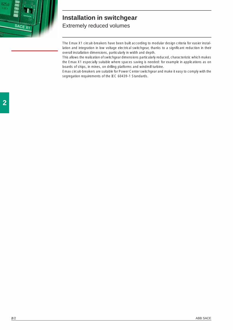
ABB SACE2/2
2
Installation in switchgear Extremely reduced volumes
The Emax X1 circuit-breakers have been built according to modular design criteria for easier instal-lation and integration in low voltage electrical switchgear, thanks to a signifi cant reduction in their overall installation dimensions, particularly in width and depth.This allows the realization of switchgear dimensions particularly reduced, characteristic which makes the Emax X1 especially suitable where spaces saving is needed: for example in applications as on boards of ships, in mines, on drilling platforms and windmill turbine.Emax circuit-breakers are suitable for Power Center switchgear and make it easy to comply with the segregation requirements of the IEC 60439-1 Standards.
X1_cap_2_01.indd 2X1_cap_2_01.indd 2 4-04-2007 9:47:234-04-2007 9:47:23
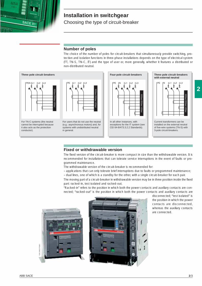
ABB SACE 2/3
2
1SD
C20
0527
F000
1
Number of polesThe choice of the number of poles for circuit-breakers that simultaneously provide switching, pro-tection and isolation functions in three-phase installations depends on the type of electrical system (TT, TN-S, TN-C, IT) and the type of user or, more generally, whether it features a distributed or non-distributed neutral.
Three-pole circuit-breakers
For TN-C systems (the neutral cannot be interrupted because it also acts as the protection conductor).
Four-pole circuit-breakers
In all other instances, with exceptions for the IT system (see CEI 64-8/473.3.2.2 Standards).
Three-pole circuit-breakers with external neutral
Current transformers can be installed on the external neutral of fi ve-wire systems (TN-S) with 3-pole circuit-breakers.
Installation in switchgear Choosing the type of circuit-breaker
For users that do not use the neutral (e.g.: asynchronous motors) and, for systems with undistributed neutral in general.
Fixed or withdrawable versionThe fi xed version of the circuit-breaker is more compact in size than the withdrawable version. It is recommended for installations that can tolerate service interruptions in the event of faults or pro-grammed maintenance.The withdrawable version of the circuit-breaker is recommended for: – applications that can only tolerate brief interruptions due to faults or programmed maintenance;– dual lines, one of which is a standby for the other, with a single circuit-breaker for each pair.
The moving part of a circuit-breaker in withdrawable version may be in three position inside the fi xed part: racked-in, test isolated and racked-out. “Racked-in” refers to the position in which both the power contacts and auxiliary contacts are con-nected; “racked-out” is the position in which both the power contacts and auxiliary contacts are
disconnected; “test isolated” is the position in which the power contacts are disconnected, whereas the auxiliary contacts are connected.
X1_cap_2_01.indd 3X1_cap_2_01.indd 3 4-04-2007 9:47:244-04-2007 9:47:24
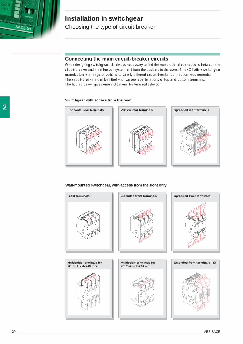
ABB SACE2/4
2
Connecting the main circuit-breaker circuits When designing switchgear, it is always necessary to fi nd the most rational connections between the circuit-breaker and main busbar system and from the busbars to the users. Emax X1 offers switchgear manufacturers a range of options to satisfy different circuit-breaker connection requirements.The circuit-breakers can be fi tted with various combinations of top and bottom terminals. The fi gures below give some indications for terminal selection.
Switchgear with access from the rear:
Installation in switchgear Choosing the type of circuit-breaker
Horizontal rear terminals Vertical rear terminals
Front terminals Extended front terminals Spreaded front terminals
Multicable terminals for FC CuAl - 4x240 mm2
Wall-mounted switchgear, with access from the front only:
Spreaded rear terminals
Multicable terminals for FC CuAl - 2x240 mm2
Extended front terminals - EF
X1_cap_2_01.indd 4X1_cap_2_01.indd 4 4-04-2007 9:47:264-04-2007 9:47:26
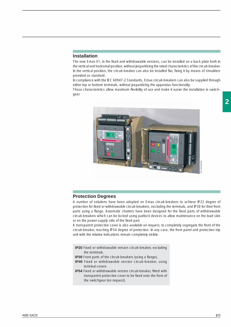
ABB SACE 2/5
2
1SD
C20
0528
F000
1
Protection Degrees A number of solutions have been adopted on Emax circuit-breakers to achieve IP22 degree of protection for fi xed or withdrawable circuit-breakers, excluding the terminals, and IP30 for their front parts using a fl ange. Automatic shutters have been designed for the fi xed parts of withdrawable circuit-breakers which can be locked using padlock devices to allow maintenance on the load side or on the power-supply side of the fi xed part.A transparent protective cover is also available on request, to completely segregate the front of the circuit-breaker, reaching IP54 degree of protection. In any case, the front panel and protection trip unit with the relative indications remain completely visible.
Installation The new Emax X1, in the fi xed and withdrawable versions, can be installed on a back plate both in the vertical and horizontal position, without jeopardising the rated characteristics of the circuit-breaker. In the vertical position, the circuit-breaker can also be installed fl at, fi xing it by means of shoulders provided as standard.In compliance with the IEC 60947-2 Standards, Emax circuit-breakers can also be supplied through either top or bottom terminals, without jeopardizing the apparatus functionality.Those characteristics allow maximum fl exibility of use and make it easier the installation in switch-gear.
IP20 Fixed or withdrawable version circuit-breaker, excluding the terminals.
IP30 Front parts of the circuit-breakers (using a fl ange).IP40 Fixed or withdrawable version circuit-breaker, using
terminal coversIP54 Fixed or withdrawable version circuit-breaker, fi tted with
transparent protective cover to be fi xed onto the front of the switchgear (on request).
X1_cap_2_01.indd 5X1_cap_2_01.indd 5 4-04-2007 9:47:274-04-2007 9:47:27
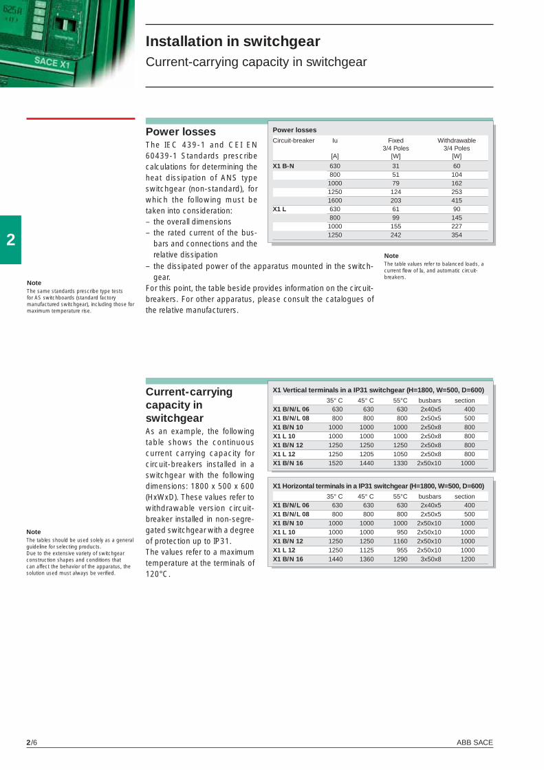
ABB SACE2/6
2
Installation in switchgear Current-carrying capacity in switchgear
Power lossesThe IEC 439-1 and CEI EN 60439-1 Standards prescribe calculations for determining the heat dissipation of ANS type switchgear (non-standard), for which the following must be taken into consideration:– the overall dimensions– the rated current of the bus-
bars and connections and the relative dissipation
NoteThe same standards prescribe type tests for AS switchboards (standard factory manufactured switchgear), including those for maximum temperature rise.
NoteThe table values refer to balanced loads, a current fl ow of Iu, and automatic circuit-breakers.
– the dissipated power of the apparatus mounted in the switch-gear.
For this point, the table beside provides information on the circuit-breakers. For other apparatus, please consult the catalogues of the relative manufacturers.
Power losses
Circuit-breaker Iu Fixed Withdrawable 3/4 Poles 3/4 Poles [A] [W] [W]
X1 B-N 630 31 60 800 51 104 1000 79 162 1250 124 253 1600 203 415X1 L 630 61 90 800 99 145 1000 155 227 1250 242 354
NoteThe tables should be used solely as a general guideline for selecting products.Due to the extensive variety of switchgear construction shapes and conditions that can affect the behavior of the apparatus, the solution used must always be verifi ed.
Current-carrying capacity in switchgearAs an example, the following table shows the continuous current carrying capacity for circuit-breakers installed in a switchgear with the following dimensions: 1800 x 500 x 600 (HxWxD). These values refer to withdrawable version circuit-breaker installed in non-segre-gated switchgear with a degree of protection up to IP31.The values refer to a maximum temperature at the terminals of 120°C.
X1 Vertical terminals in a IP31 switchgear (H=1800, W=500, D=600)
35° C 45° C 55°C busbars sectionX1 B/N/L 06 630 630 630 2x40x5 400X1 B/N/L 08 800 800 800 2x50x5 500X1 B/N 10 1000 1000 1000 2x50x8 800X1 L 10 1000 1000 1000 2x50x8 800X1 B/N 12 1250 1250 1250 2x50x8 800X1 L 12 1250 1205 1050 2x50x8 800X1 B/N 16 1520 1440 1330 2x50x10 1000
X1 Horizontal terminals in a IP31 switchgear (H=1800, W=500, D=600)
35° C 45° C 55°C busbars sectionX1 B/N/L 06 630 630 630 2x40x5 400X1 B/N/L 08 800 800 800 2x50x5 500X1 B/N 10 1000 1000 1000 2x50x10 1000X1 L 10 1000 1000 950 2x50x10 1000X1 B/N 12 1250 1250 1160 2x50x10 1000X1 L 12 1250 1125 955 2x50x10 1000X1 B/N 16 1440 1360 1290 3x50x8 1200
X1_cap_2_01.indd 6X1_cap_2_01.indd 6 4-04-2007 9:47:284-04-2007 9:47:28
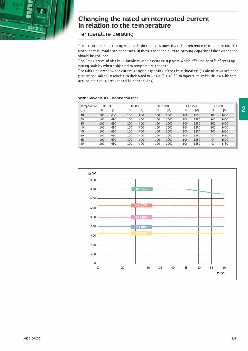
ABB SACE 2/7
2
10 20 30 35 40 45 50 55 60
Iu [A]
T [°C]
1800
1600
1400
1200
1000
800
600
400
200
0
X1 800
X1 1250
X1 1600
X1 1000
X1 630
Changing the rated uninterrupted current in relation to the temperature Temperature derating
The circuit-breakers can operate at higher temperatures than their reference temperature (40 °C) under certain installation conditions. In these cases the current-carrying capacity of the switchgear should be reduced.The Emax series of air circuit-breakers uses electronic trip units which offer the benefi t of great op-erating stability when subjected to temperature changes.The tables below show the current-carrying capacities of the circuit-breakers (as absolute values and percentage values) in relation to their rated values at T = 40 °C (temperature inside the switchboard around the circuit-breaker and its connections).
Withdrawable X1 - horizontal rear
Temperature X1 630 X1 800 X1 1000 X1 1250 X1 1600 [°C] % [A] % [A] % [A] % [A] % [A]
10 100 630 100 800 100 1000 100 1250 100 160020 100 630 100 800 100 1000 100 1250 100 160030 100 630 100 800 100 1000 100 1250 100 160040 100 630 100 800 100 1000 100 1250 100 160045 100 630 100 800 100 1000 100 1250 100 160050 100 630 100 800 100 1000 100 1250 97 155055 100 630 100 800 100 1000 100 1250 94 150060 100 630 100 800 100 1000 100 1250 93 1480
X1_cap_2_01.indd 7X1_cap_2_01.indd 7 4-04-2007 9:47:294-04-2007 9:47:29
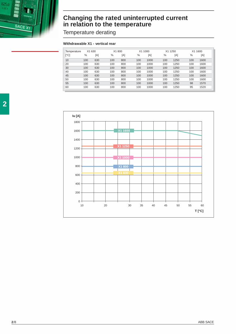
ABB SACE2/8
2
10 20 30 35 40 45 50 55 60
Iu [A]
T [°C]
1800
1600
1400
1200
1000
800
600
400
200
0
X1 800
X1 1250
X1 1600
X1 1000
X1 630
Withdrawable X1 - vertical rear
Temperature X1 630 X1 800 X1 1000 X1 1250 X1 1600 [°C] % [A] % [A] % [A] % [A] % [A]
10 100 630 100 800 100 1000 100 1250 100 160020 100 630 100 800 100 1000 100 1250 100 160030 100 630 100 800 100 1000 100 1250 100 160040 100 630 100 800 100 1000 100 1250 100 160045 100 630 100 800 100 1000 100 1250 100 160050 100 630 100 800 100 1000 100 1250 100 160055 100 630 100 800 100 1000 100 1250 98 157060 100 630 100 800 100 1000 100 1250 95 1520
Changing the rated uninterrupted current in relation to the temperature Temperature derating
X1_cap_2_01.indd 8X1_cap_2_01.indd 8 4-04-2007 9:47:294-04-2007 9:47:29
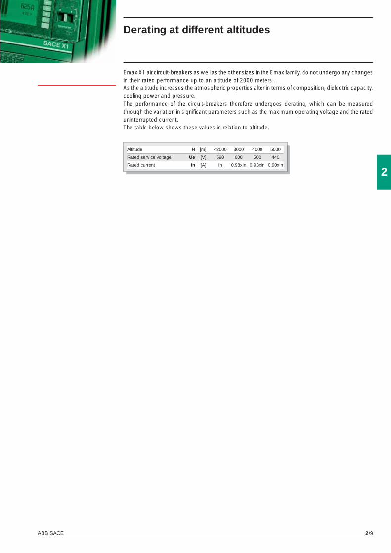
ABB SACE 2/9
2
Altitude H [m] <2000 3000 4000 5000
Rated service voltage Ue [V] 690 600 500 440
Rated current In [A] In 0.98xIn 0.93xIn 0.90xIn
Emax X1 air circuit-breakers as well as the other sizes in the Emax family, do not undergo any changes in their rated performance up to an altitude of 2000 meters.As the altitude increases the atmospheric properties alter in terms of composition, dielectric capacity, cooling power and pressure.The performance of the circuit-breakers therefore undergoes derating, which can be measured through the variation in signifi cant parameters such as the maximum operating voltage and the rated uninterrupted current.The table below shows these values in relation to altitude.
Derating at different altitudes
X1_cap_2_01.indd 9X1_cap_2_01.indd 9 4-04-2007 9:47:304-04-2007 9:47:30
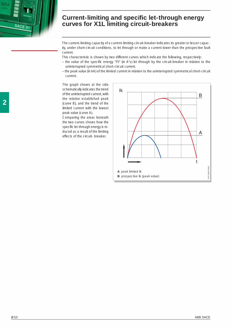
ABB SACE2/10
2
1SD
C20
0091
F000
1
Current-limiting and specifi c let-through energy curves for X1L limiting circuit-breakers
A peak limited Ik
B prospective Ik (peak value)
The current-limiting capacity of a current-limiting circuit-breaker indicates its greater or lesser capac-ity, under short-circuit conditions, to let through or make a current lower than the prospective fault current. This characteristic is shown by two different curves which indicate the following, respectively:– the value of the specifi c energy “I2t” (in A2s) let through by the circuit-breaker in relation to the
uninterrupted symmetrical short-circuit current.– the peak value (in kA) of the limited current in relation to the uninterrupted symmetrical short-circuit
current.
The graph shown at the side schematically indicates the trend of the uninterrupted current, with the relative established peak (curve B), and the trend of the limited current with the lowest peak value (curve A).Comparing the areas beneath the two curves shows how the specifi c let-through energy is re-duced as a result of the limiting effects of the circuit- breaker.
Ik
X1_cap_2_01.indd 10X1_cap_2_01.indd 10 4-04-2007 9:47:304-04-2007 9:47:30

ABB SACE 2/11
2
X1L
X1L
380/415
690
380/415
690
1SD
C20
0529
F000
11S
DC
2005
30F0
001
lrms prospective symmetrical short-circuit current
lp peak currentl2t specifi c let-through energy
at the voltages indicated
Specifi c let-through energy curves
Current-limiting curves
X1_cap_2_01.indd 11X1_cap_2_01.indd 11 4-04-2007 9:47:304-04-2007 9:47:30
X1_cap_3_00.indd 2X1_cap_3_00.indd 2 4-04-2007 9:50:204-04-2007 9:50:20
3
ABB SACE 3/1
Trip units and related accessories
ContentsProtection trip units and trip curves
PR331/P ............................................................................................................................... 3/2
PR332/P ............................................................................................................................. 3/9
PR333/P .............................................................................................................................. 3/23
Accessories for protection trip units
PR330/V Measurement Module ........................................................................................... 3/34
PR330/D-M Communication Module .................................................................................... 3/35
PR330/R actuator module .................................................................................................... 3/35
PR030/B power supply unit .................................................................................................. 3/36
Interface from front of HMI030 panel .................................................................................... 3/36
BT030 Communication unit .................................................................................................. 3/36
PR010/T confi guration test unit ............................................................................................ 3/37
PR021/K Signalling unit ........................................................................................................ 3/38
Communication devices and systems
Industrial networking and ABB SACE Emax ....................................................................... 3/39
PR330/D-M .......................................................................................................................... 3/41
EP010 – FBP ....................................................................................................................... 3/41
Measurement, signalling and available data functions ......................................................... 3/42
SD-View 2000 ....................................................................................................................... 3/43
BT030 ............................................................................................. ..................................... 3/45
SD-Pocket ............................................................................................................................ 3/45
SD-TestBus2 ......................................................................................................................... 3/46
X1_cap_3_00.indd 3X1_cap_3_00.indd 3 4-04-2007 9:50:264-04-2007 9:50:26
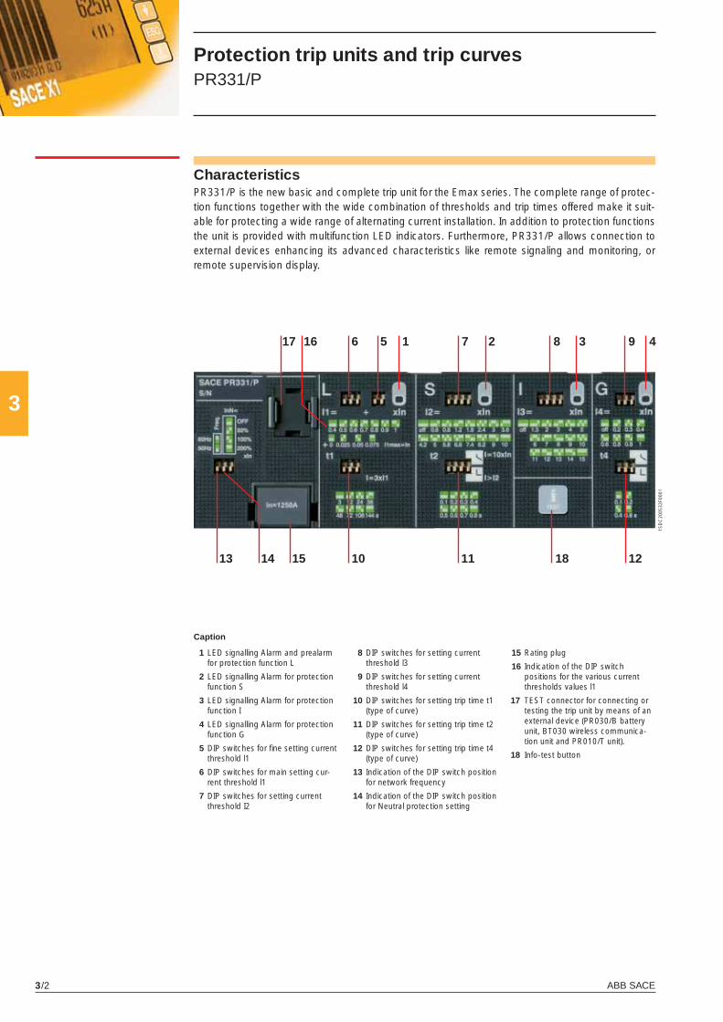
ABB SACE3/2
3
4
10 13
6 7 5
14
1 2 3 8 9
11 12 15
16
1SD
C20
0532
F000
1
17
18
1 LED signalling Alarm and prealarm for protection function L
2 LED signalling Alarm for protection function S
3 LED signalling Alarm for protection function I
4 LED signalling Alarm for protection function G
5 DIP switches for fi ne setting current threshold l1
6 DIP switches for main setting cur-rent threshold l1
7 DIP switches for setting current threshold I2
Characteristics PR331/P is the new basic and complete trip unit for the Emax series. The complete range of protec-tion functions together with the wide combination of thresholds and trip times offered make it suit-able for protecting a wide range of alternating current installation. In addition to protection functions the unit is provided with multifunction LED indicators. Furthermore, PR331/P allows connection to external devices enhancing its advanced characteristics like remote signaling and monitoring, or remote supervision display.
Caption
Protection trip units and trip curves PR331/P
8 DIP switches for setting current threshold l3
9 DIP switches for setting current threshold l4
10 DIP switches for setting trip time t1 (type of curve)
11 DIP switches for setting trip time t2 (type of curve)
12 DIP switches for setting trip time t4 (type of curve)
13 Indication of the DIP switch position for network frequency
14 Indication of the DIP switch position for Neutral protection setting
15 Rating plug
16 Indication of the DIP switch positions for the various current thresholds values l1
17 TEST connector for connecting or testing the trip unit by means of an external device (PR030/B battery unit, BT030 wireless communica-tion unit and PR010/T unit).
18 Info-test button
X1_cap_3_01.indd 2X1_cap_3_01.indd 2 4-04-2007 9:51:004-04-2007 9:51:00
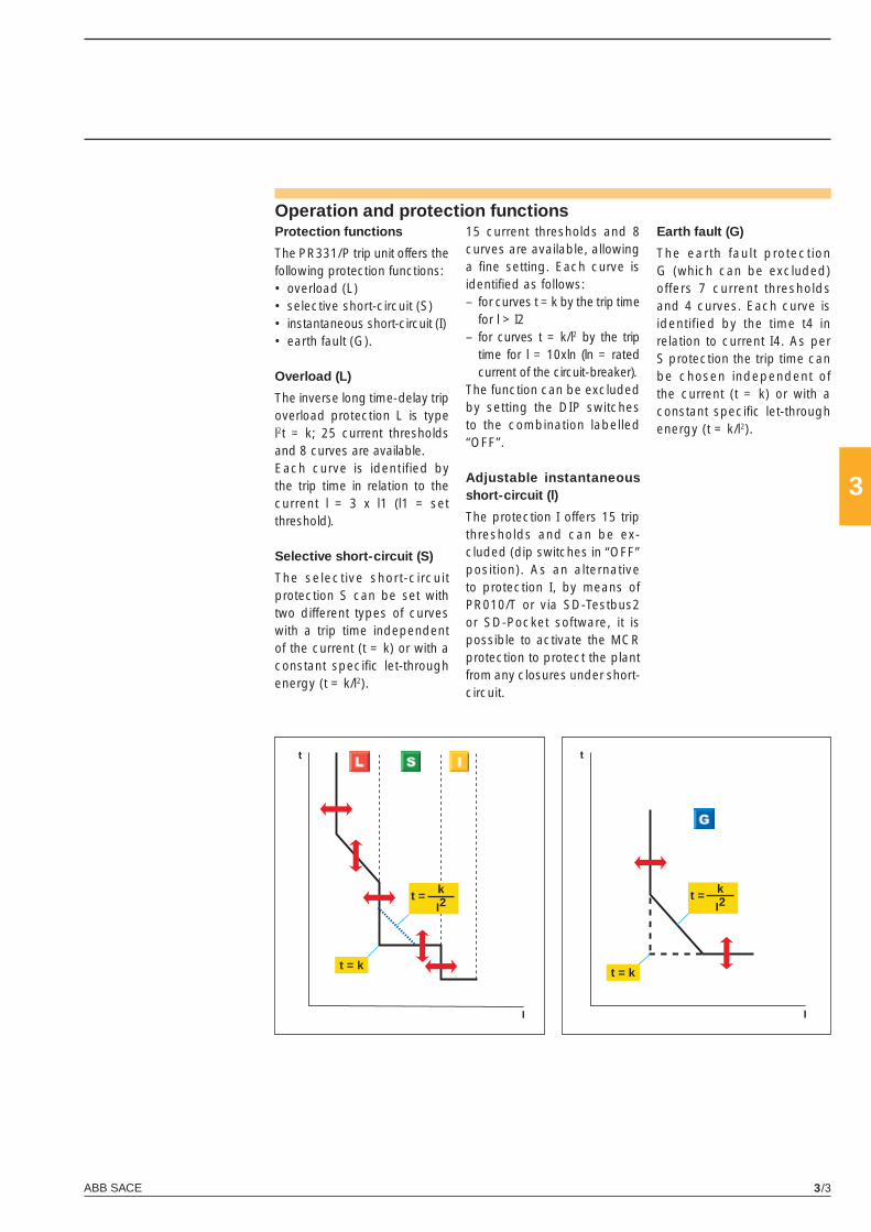
ABB SACE 3/3
3
�
�
�
�
t = k
I2
t = k
t = k
I2
t = k
Operation and protection functions Protection functions
The PR331/P trip unit offers the following protection functions: • overload (L) • selective short-circuit (S)• instantaneous short-circuit (I) • earth fault (G). Overload (L)
The inverse long time-delay trip overload protection L is type l2t = k; 25 current thresholds and 8 curves are available.Each curve is identified by the trip time in relation to the current l = 3 x l1 (l1 = set threshold).
Selective short-circuit (S)
The selective short-circuit protection S can be set with two different types of curves with a trip time independent of the current (t = k) or with a constant specifi c let-through energy (t = k/l2).
15 current thresholds and 8 curves are available, allowing a fi ne setting. Each curve is identifi ed as follows:– for curves t = k by the trip time
for l > I2– for curves t = k/l2 by the trip
time for l = 10xln (ln = rated current of the circuit-breaker).
The function can be excluded by setting the DIP switches to the combination labelled “OFF”.
Adjustable instantaneous short-circuit (l)
The protection I offers 15 trip thresholds and can be ex-cluded (dip switches in “OFF” position). As an alternative to protection I, by means of PR010/T or via SD-Testbus2 or SD-Pocket software, it is possible to activate the MCR protection to protect the plant from any closures under short-circuit.
Earth fault (G)
The earth fault protection G (which can be excluded) offers 7 current thresholds and 4 curves. Each curve is identified by the time t4 in relation to current I4. As per S protection the trip time can be chosen independent of the current (t = k) or with a constant specifi c let-through energy (t = k/l2).
X1_cap_3_01.indd 3X1_cap_3_01.indd 3 4-04-2007 9:51:034-04-2007 9:51:03

ABB SACE3/4
3
Protection trip units and trip curves PR331/P
User interface
The user communicates directly with the trip unit in the trip parameter preparation stage by means of the dip switches.Up to four LEDs (according to the version) are also available for signalling.These LEDs (one for each protection) are active when:• a protection is timing. For protection L the prealarm status is also shown;• a protection has tripped (the corresponding LED is activated by pressing the “Info/Test” pu-
shbutton);• a failure in connection of a current sensor or in the trip coil is detected. The indication is active
when the unit is powered (through current sensors or an auxiliary power supply)• wrong rating plug for the circuit-breaker. The protection tripped indication works even with the circuit-breaker open, without the need for any internal or external auxiliary power supply. This information is available for 48 hours of inactivity after the trip and is still available after reclosing. If the query is made more than 48 hours later it is suffi cient to connect a PR030/B battery unit, PR010/T, or a BT030 wireless communication unit.There is programmable contact in the device, which can be set using PR010/T, SD-Testbus2 or SD Pocket and combined with numerous events.
Communication
By means of the BT030 wireless communication unit, PR331/P can be connected to a pocket PC (PDA) or to a personal computer, extending the range of information available for the user. In fact, by means of ABB SACE’s SD-Pocket communication software, It is possible to read the values of the currents fl owing through the circuit-breaker, the value of the last 20 interrupted currents, and the protection settings.PR331/P can also be connected to the HMI030 unit, for the remote user interfacing.
Setting the neutral
Protection of the neutral can be set at 50%, 100% or 200% of the phase currents. In particular, adjust-ment of the neutral at 200% of the phase current is possible if the following inequality is respected: I1 x In x %N < Iu. The user can also switch the neutral protection OFF.
Test Function
The Test function is carried out by means of the info/Test pushbutton and the PR030/B battery unit (or BT030) fi tted with a polarized connector housed on the bottom of the box, which allows the device to be connected to the test connector on the front of PR331/P releases. The PR331/P electronic trip unit can be tested by using the PR010/T test and confi guration unit by connecting it to the TEST connector.
X1_cap_3_01.indd 4X1_cap_3_01.indd 4 4-04-2007 9:51:044-04-2007 9:51:04
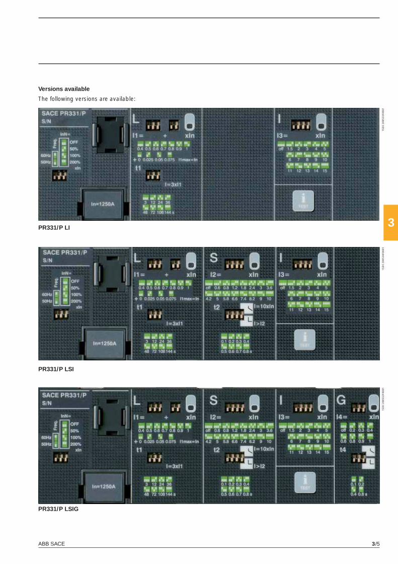
ABB SACE 3/5
3PR331/P LI
PR331/P LSI
PR331/P LSIG
1SD
C20
0533
F000
11S
DC
2005
34F0
001
1SD
C20
0532
F000
1
Versions available
The following versions are available:
X1_cap_3_01.indd 5X1_cap_3_01.indd 5 4-04-2007 9:51:054-04-2007 9:51:05
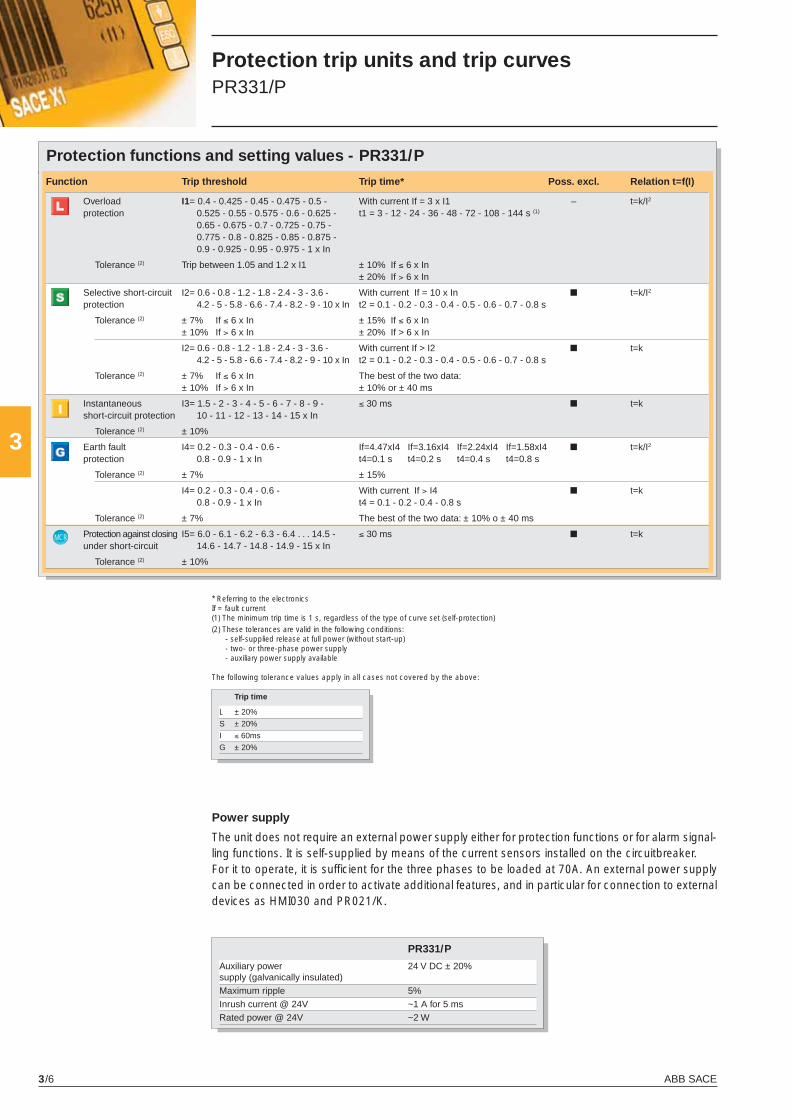
ABB SACE3/6
3
MCR
Protection trip units and trip curves PR331/P
Protection functions and setting values - PR331/P
* Referring to the electronicsIf = fault current(1) The minimum trip time is 1 s, regardless of the type of curve set (self-protection) (2) These tolerances are valid in the following conditions:
- self-supplied release at full power (without start-up) - two- or three-phase power supply - auxiliary power supply available
The following tolerance values apply in all cases not covered by the above:
Power supply
The unit does not require an external power supply either for protection functions or for alarm signal-ling functions. It is self-supplied by means of the current sensors installed on the circuitbreaker. For it to operate, it is suffi cient for the three phases to be loaded at 70A. An external power supply can be connected in order to activate additional features, and in particular for connection to external devices as HMI030 and PR021/K.
PR331/P
Auxiliary power 24 V DC ± 20%supply (galvanically insulated) Maximum ripple 5% Inrush current @ 24V ~1 A for 5 ms Rated power @ 24V ~2 W
Function Trip threshold Trip time* Poss. excl. Relation t=f(I)
Overload I1= 0.4 - 0.425 - 0.45 - 0.475 - 0.5 - With current If = 3 x I1 – t=k/I2
protection 0.525 - 0.55 - 0.575 - 0.6 - 0.625 - t1 = 3 - 12 - 24 - 36 - 48 - 72 - 108 - 144 s (1)
0.65 - 0.675 - 0.7 - 0.725 - 0.75 - 0.775 - 0.8 - 0.825 - 0.85 - 0.875 - 0.9 - 0.925 - 0.95 - 0.975 - 1 x In
Tolerance (2) Trip between 1.05 and 1.2 x I1 ± 10% If ≤ 6 x In ± 20% If > 6 x In
Selective short-circuit I2= 0.6 - 0.8 - 1.2 - 1.8 - 2.4 - 3 - 3.6 - With current If = 10 x In ■ t=k/I2
protection 4.2 - 5 - 5.8 - 6.6 - 7.4 - 8.2 - 9 - 10 x In t2 = 0.1 - 0.2 - 0.3 - 0.4 - 0.5 - 0.6 - 0.7 - 0.8 s
Tolerance (2) ± 7% If ≤ 6 x In ± 15% If ≤ 6 x In ± 10% If > 6 x In ± 20% If > 6 x In
I2= 0.6 - 0.8 - 1.2 - 1.8 - 2.4 - 3 - 3.6 - With current If > I2 ■ t=k 4.2 - 5 - 5.8 - 6.6 - 7.4 - 8.2 - 9 - 10 x In t2 = 0.1 - 0.2 - 0.3 - 0.4 - 0.5 - 0.6 - 0.7 - 0.8 s
Tolerance (2) ± 7% If ≤ 6 x In The best of the two data: ± 10% If > 6 x In ± 10% or ± 40 ms
Instantaneous I3= 1.5 - 2 - 3 - 4 - 5 - 6 - 7 - 8 - 9 - ≤ 30 ms ■ t=k short-circuit protection 10 - 11 - 12 - 13 - 14 - 15 x In
Tolerance (2) ± 10%
Earth fault I4= 0.2 - 0.3 - 0.4 - 0.6 - If=4.47xI4 If=3.16xI4 If=2.24xI4 If=1.58xI4 ■ t=k/I2
protection 0.8 - 0.9 - 1 x In t4=0.1 s t4=0.2 s t4=0.4 s t4=0.8 s
Tolerance (2) ± 7% ± 15%
I4= 0.2 - 0.3 - 0.4 - 0.6 - With current If > I4 ■ t=k 0.8 - 0.9 - 1 x In t4 = 0.1 - 0.2 - 0.4 - 0.8 s
Tolerance (2) ± 7% The best of the two data: ± 10% o ± 40 ms
Protection against closing I5= 6.0 - 6.1 - 6.2 - 6.3 - 6.4 . . . 14.5 - ≤ 30 ms ■ t=k under short-circuit 14.6 - 14.7 - 14.8 - 14.9 - 15 x In
Tolerance (2) ± 10%
Trip time
L ± 20%
S ± 20%
I ≤ 60ms
G ± 20%
X1_cap_3_01.indd 6X1_cap_3_01.indd 6 4-04-2007 9:51:094-04-2007 9:51:09
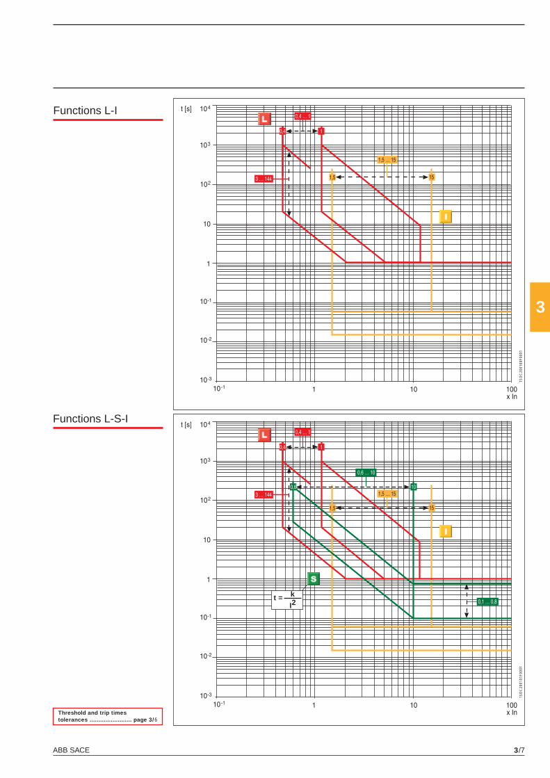
ABB SACE 3/7
3
t = k
I2
1SD
C20
0100
F000
11S
DC
2001
01F0
001
Functions L-I
Functions L-S-I
Threshold and trip times tolerances ........................ page 3/6
X1_cap_3_01.indd 7X1_cap_3_01.indd 7 4-04-2007 9:51:104-04-2007 9:51:10
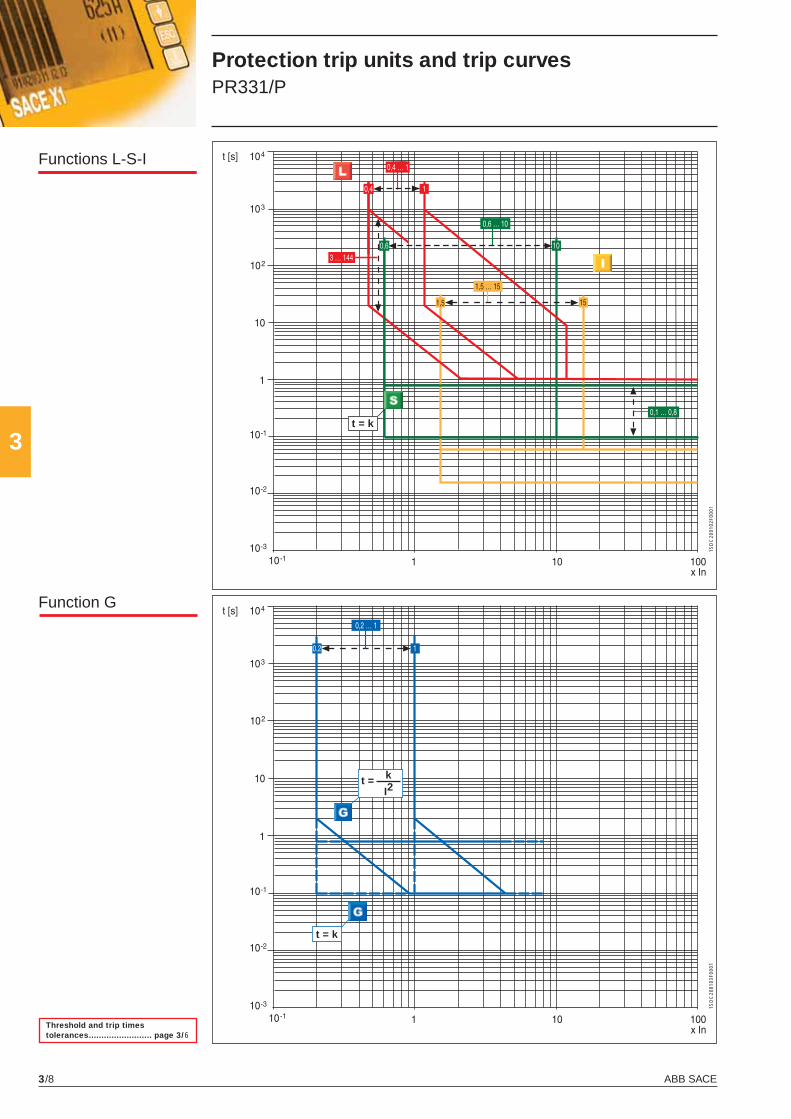
ABB SACE3/8
3t = k
t = k
t = k
I2
1SD
C20
0102
F000
11S
DC
2001
03F0
001
Functions L-S-I
Function G
Threshold and trip times tolerances ......................... page 3/6
Protection trip units and trip curves PR331/P
X1_cap_3_01.indd 8X1_cap_3_01.indd 8 4-04-2007 9:51:114-04-2007 9:51:11
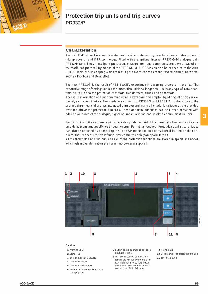
ABB SACE 3/9
3
10
7
2 31
5
48 6
9 11
1SD
C20
0535
F000
1
Protection trip units and trip curves PR332/P
CharacteristicsThe PR332/P trip unit is a sophisticated and fl exible protection system based on a state-of-the art microprocessor and DSP technology. Fitted with the optional internal PR330/D-M dialogue unit, PR332/P turns into an intelligent protection, measurement and communication device, based on the Modbus® protocol. By means of the PR330/D-M, PR332/P can also be connected to the ABB EP010 Fieldbus plug adapter, which makes it possible to choose among several different networks, such as Profi bus and DeviceNet.
The new PR332/P is the result of ABB SACE’s experience in designing protection trip units. The exhaustive range of settings makes this protection unit ideal for general use in any type of installation, from distribution to the protection of motors, transformers, drives and generators.Access to information and programming using a keyboard and graphic liquid crystal display is ex-tremely simple and intuitive. The interface is common to PR332/P and PR333/P in order to give to the user maximum ease of use. An integrated ammeter and many other additional features are provided over and above the protection functions. These additional functions can be further increased with addition on board of the dialogue, signalling, measurement, and wireless communication units.
Functions S and G can operate with a time delay independent of the current (t = k) or with an inverse time delay (constant specifi c let-through energy: I2t = k), as required. Protection against earth faults can also be obtained by connecting the PR332/P trip unit to an external toroid located on the con-ductor that connects the transformer star centre to earth (homopolar toroid).All the thresholds and trip curve delays of the protection functions are stored in special memories which retain the information even when no power is supplied.
1 Warning LED
2 Alarm LED
3 Rear-light graphic display
4 Cursor UP button
5 Cursor DOWN button
6 ENTER button to confi rm data or change pages
9 Rating plug
10 Serial number of protection trip unit
11 Info-test button
Caption
7 Button to exit submenus or cancel operations (ESC)
8 Test connector for connecting or testing the release by means of an external device (PR030/B battery unit, BT030 wireless communica-tion unit and PR010/T unit)
X1_cap_3_01.indd 9X1_cap_3_01.indd 9 4-04-2007 9:51:124-04-2007 9:51:12
ABB SACE3/10
3
Protection trip units and trip curves PR332/P
Operation, protection functions and self-testBasic Protection functions
The PR332/P trip unit offers the following protection functions(according to the version):• overload (L)• selective short-circuit (S)• instantaneous short-circuit (I)• earth fault (G)• phase unbalance (U)• self-protection against overtemperature (OT)• thermal memory for functions
L and S• zone selectivity for functions
S and G• residual current (Rc) with
external toroid• source ground return with
external toroid• closing under short-circuit
(MCR).
Setting the neutral
In PR332/P, and PR333/P as well, the neutral protection is
50% of the value set for phase protection in the standard ver-sion. The neutral protection can be excluded or set to 100%. In installations where very high harmonics occur, the resulting current at the neutral can be higher than that of the phases. Therefore it is possible to set the neutral protection at 150% or 200% of the value set for the phases. In this case it is neces-sary to reduce the setting of protection L accordingly.The table below lists the neutral settings for the various possible combinations between type of circuit-breaker and the thresh-old I1 setting.
Start-up function
The start-up function allows protections S, I and G to oper-ate with higher trip thresholds during the start-up phase. This
avoids untimely tripping caused by the high inrush currents of certain loads (motors, trans-formers, lamps).The start-up phase lasts from 100 ms to 30 s, in steps of 0.01 s. It is automatically recognized by the PR332/P release, when the peak value of the maximum current exceeds the threshold set by the user. A new start-up becomes possible after the current has fallen below the set threshold, if the release is sup-plied from an external source.
Adjustable neutral protection settings
Threshold I1 settings (overload protection)
Circuit-breaker model 0.4 ≤ I1 ≤ 0.5 0.5 < I1 ≤ 0.66 0.66 < I1 ≤ 1(*)
X1 0-50-100-150-200% 0-50-100-150% 0-50-100%
(*) The setting I1 =1 indicates the maximum overload protection setting. The actual maximum setting allowable must take into account any derating based on temperature, the terminals used and the altitude (see the “Installations” chapter)
X1_cap_3_01.indd 10X1_cap_3_01.indd 10 4-04-2007 9:51:154-04-2007 9:51:15
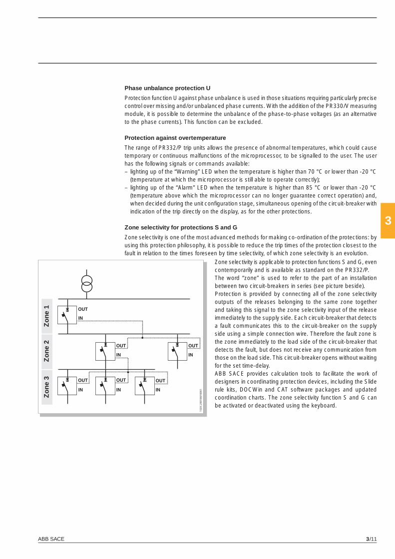
ABB SACE 3/11
3
Phase unbalance protection U
Protection function U against phase unbalance is used in those situations requiring particularly precise control over missing and/or unbalanced phase currents. With the addition of the PR330/V measuring module, it is possible to determine the unbalance of the phase-to-phase voltages (as an alternative to the phase currents). This function can be excluded.
Protection against overtemperature
The range of PR332/P trip units allows the presence of abnormal temperatures, which could cause temporary or continuous malfunctions of the microprocessor, to be signalled to the user. The user has the following signals or commands available:– lighting up of the “Warning” LED when the temperature is higher than 70 °C or lower than -20 °C
(temperature at which the microprocessor is still able to operate correctly);– lighting up of the “Alarm” LED when the temperature is higher than 85 °C or lower than -20 °C
(temperature above which the microprocessor can no longer guarantee correct operation) and, when decided during the unit confi guration stage, simultaneous opening of the circuit-breaker with indication of the trip directly on the display, as for the other protections.
Zone selectivity for protections S and G
Zone selectivity is one of the most advanced methods for making co-ordination of the protections: by using this protection philosophy, it is possible to reduce the trip times of the protection closest to the fault in relation to the times foreseen by time selectivity, of which zone selectivity is an evolution.
Zo
ne 3
Zo
ne 2
Zo
ne 1
Zone selectivity is applicable to protection functions S and G, even contemporarily and is available as standard on the PR332/P.The word “zone” is used to refer to the part of an installation between two circuit-breakers in series (see picture beside). Protection is provided by connecting all of the zone selectivity outputs of the releases belonging to the same zone together and taking this signal to the zone selectivity input of the release immediately to the supply side. Each circuit-breaker that detects a fault communicates this to the circuit-breaker on the supply side using a simple connection wire. Therefore the fault zone is the zone immediately to the load side of the circuit-breaker that detects the fault, but does not receive any communication from those on the load side. This circuit-breaker opens without waiting for the set time-delay. ABB SACE provides calculation tools to facilitate the work of designers in coordinating protection devices, including the Slide rule kits, DOCWin and CAT software packages and updated coordination charts. The zone selectivity function S and G can be activated or deactivated using the keyboard.
1SD
C20
0186
F000
1
X1_cap_3_01.indd 11X1_cap_3_01.indd 11 4-04-2007 9:51:164-04-2007 9:51:16
ABB SACE3/12
3
Self-diagnosis
The PR332/P range of trip units contains an electronic circuit which periodically checks the continu-ity of internal connections (trip coil and each current sensor, including the Source Ground Return when present).In the case of a malfunction an alarm message appears directly on the display. The Alarm is high-lighted by the Alarm LED as well.
Residual Current
Different solutions are available for integrated residual current protection. The basic choice is PR332/P-LSIRc, which has all the characteristics of PR332/P-LSI and residual current protection as well. When additional features are required, the solution is PR332/P-LSIG with an additional PR330/V module (see next paragraph). Using this confi guration, residual current protection is added to a unit, having the features of PR332/P-LSI and all the add-ons described for the PR330/V module, such as voltage protection and advanced measurement functions. Residual current protection acts by measuring the current from the external dedicated toroid.
Test Functions
Once enabled from the menu, the “info/Test” pushbutton on the front of the trip unit allows correct operation of the chain consisting of the microprocessor, trip coil and circuit-breaker tripping mecha-nism to be checked.The control menu also includes the option of testing correct operation of the display and signaling LEDs.By means of the front multi-pin connector it is possible to apply a PR010/T Test unit which allows the functions of the PR331/P, PR332/P and PR333/P ranges of trip units to be tested and checked.
User interface
The human-machine interface (HMI) of the device is made up of a wide graphic display, LEDs, and browsing pushbuttons. The interface is designed to provide maximum simplicity.The language can be selected from among fi ve available options: Italian, English, German, French and Spanish.As in the previous generation of releases, a password system is used to manage the “Read” or “Edit” modes. The default password, 0001, can be modifi ed by the user.The protection parameters (curves and trip thresholds) can be set directly via the HMI of the device. The parameters can only be changed when the release is operating in “Edit” mode, but the informa-tion available and the parameter settings can be checked at any time in “Read” mode. When a communication device (internal PR330/D-M modules or external BT030 device) is con-nected, it is possible to set parameters simply by downloading them into the unit (over the network for PR330/D-M, by using the SD-Pocket software and a PDA or a notebook for BT030). Param-eterisation can then be carried out quickly and automatically in an error-free way by transferring data directly from DocWin. There is programmable contact in the device, which can be set using PR010/T, SD-Testbus2 or SD Pocket and combined with numerous events.
Indicator LEDs
LEDs on the front panel of the release are used to indicate all the pre-alarms (“WARNING”) andalarms (“ALARM”). A message on the display always explicitly indicates the type of eventconcerned.Example of events indicated by the “WARNING” LED:– unbalance between phases;– pre-alarm for overload (L1>90%);– fi rst temperature threshold exceeded (70 °C);– contact wear beyond 80%;– phase rotation reversed (with optional PR330/V)
Protection trip units and trip curves PR332/P
X1_cap_3_01.indd 12X1_cap_3_01.indd 12 4-04-2007 9:51:164-04-2007 9:51:16
ABB SACE 3/13
3
Example of events indicated by the “ALARM” LED:– overload (may begin from 1.05xl1<I<1.3xl1, in accordance with the standard IEC 60947-2);– timing of function L;– timing of function S;– timing of function G;– second temperature threshold exceeded (85 °C);– contact wear 100%;– timing of Reverse Power fl ow protection (with optional PR330/V).
Data logger
By default PR332/P, as well as PR333/P, is provided with the Data Logger function, that automati-cally records in a wide memory buffer the instantaneous values of all the currents and voltages. Data can be easily downloaded from the unit by means of SD-Pocket or SD-TestBus2 applications and can be transferred to any personal computer for elaboration. The dedicated application “SD-Data logger viewer” shows clearly to the user all the relevant trip information provided by the data logger. The function freezes the recording whenever a trip occurs in case of other events, so that a detailed analysis of faults can be easily performed. SD-Pocket and SD-TestBus2 allow also reading and downloading of all the others trip information.Data logger is also very useful for network analysis in normal operating conditions.• Number of analog channels: 8• Maximum sampling rate: 4800 Hz• Maximum sampling time: 27 s (@ sampling rate 600 Hz)• 64 events tracking• 24 V DC auxiliary supply is required for this function.
When communication module PR330/D-M is present, data can be acquired and transferred through the Modbus network.
Trip information and opening data
In case a trip occurs PR332/P and PR333/P store all the needed information:• Protection tripped• Opening data (current)• Time stamp By pushing the “info/Test” pushbutton the release shows all these data directly on display.No auxiliary power supply is needed. The information is available to user for 48 hours with the circuit breaker open or without current fl owing.The information of the latest 20 trips are stored in memory.The information about the last 20 trips remains recorded in the memory and can be recovered by connecting a PR030/B battery unit or a BT030 wireless communication unit or a PR010/T test and confi guration unit or an auxiliary power supply.
Load control
Load control makes it possible to engage/disengage individual loads on the load side before the overload protection L is tripped, thereby avoiding unnecessary trips of the circuit-breaker on the supply side. This is done by means of contactors or relays (externally wired to the release), controlled by the PR332/P through the contacts of an external unit.The current thresholds and trip times are smaller than those available for selection with protection L, so that load control can be used to prevent overload tripping. An external accessory unit is required for Load Control. The function is only active when an auxiliary power supply is available.
X1_cap_3_01.indd 13X1_cap_3_01.indd 13 4-04-2007 9:51:174-04-2007 9:51:17
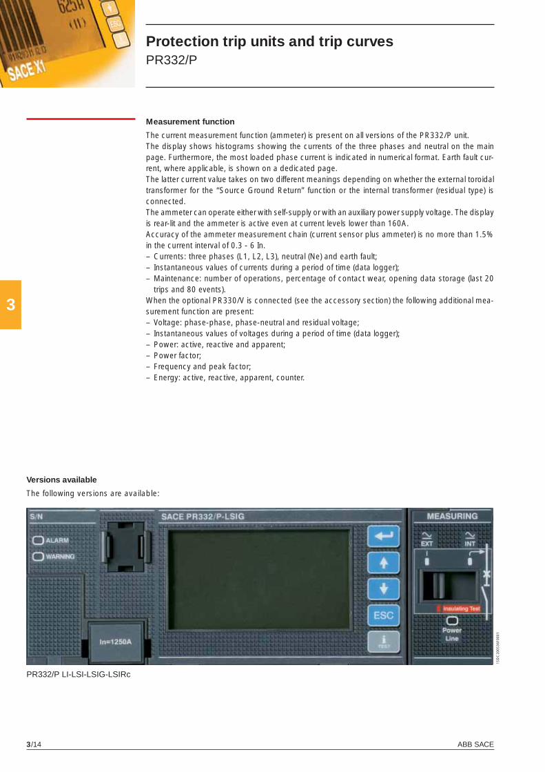
ABB SACE3/14
3
1SD
C20
0536
F000
1
PR332/P LI-LSI-LSIG-LSIRc
Measurement function
The current measurement function (ammeter) is present on all versions of the PR332/P unit.The display shows histograms showing the currents of the three phases and neutral on the main page. Furthermore, the most loaded phase current is indicated in numerical format. Earth fault cur-rent, where applicable, is shown on a dedicated page.The latter current value takes on two different meanings depending on whether the external toroidal transformer for the “Source Ground Return” function or the internal transformer (residual type) is connected.The ammeter can operate either with self-supply or with an auxiliary power supply voltage. The display is rear-lit and the ammeter is active even at current levels lower than 160A.Accuracy of the ammeter measurement chain (current sensor plus ammeter) is no more than 1.5% in the current interval of 0.3 - 6 In.– Currents: three phases (L1, L2, L3), neutral (Ne) and earth fault;– Instantaneous values of currents during a period of time (data logger);– Maintenance: number of operations, percentage of contact wear, opening data storage (last 20
trips and 80 events).When the optional PR330/V is connected (see the accessory section) the following additional mea-surement function are present:– Voltage: phase-phase, phase-neutral and residual voltage;– Instantaneous values of voltages during a period of time (data logger);– Power: active, reactive and apparent;– Power factor;– Frequency and peak factor;– Energy: active, reactive, apparent, counter.
Versions available
The following versions are available:
Protection trip units and trip curves PR332/P
X1_cap_3_01.indd 14X1_cap_3_01.indd 14 4-04-2007 9:51:184-04-2007 9:51:18
ABB SACE 3/15
3
Rc
OT
U
MCR
* Referring to the electronicsIf = fault current(1) The minimum trip value is 1 s, regardless of the type of curve set (self-protection) (2) These tolerances are valid in the following conditions: - self-supplied release at full power and/or auxiliary power supply (without start-up) - two- or three-phase power supply - trip time set ≥ 100 ms(3) Non intervention time
The following tolerance values apply in all cases not covered by the above:
Protection functions and setting values - PR332/P
Function Trip Threshold Trip Time Poss. Relation Thermal Zone threshold step time * Step excl. t=f(I) memory selectivity
Overload With current If = 3xI1 protection I1= 0.4….1 x In 0.01 x In t1= 3 s....144 s (1) 3 s – t=k/I2 ■ – Tolleranza (2) Trip between ± 10% If ≤ 6 x In 1.05 ... 1.2 x I1 ± 20% If > 6 x In
I1= 0.4….1 x In 0.01 x In With current If = 3xI1(4); t1= 3 s....144 s 3 s – t=t (α) Tolerance 1.05 ... 1.2 x I1 ± 20% If > 6 x I1 α=0.02-1-2 (in accordance with IEC 60255-3) ± 30% 2xI1≤ If ≤ 6 x I1 In
Selective short- With current I > I2 circuit protection I2= 0.6….10 x In 0.1 x In t2= 0.05 s….0.8 s (2) 0.01 s ■ t=k – ■
t2sel= 0.04 s….0.25 s 0.01 s Tolerance (2) ± 7% If ≤ 6 x In The best of the two data: ± 10% If > 6 x In ± 10% o ± 40 ms
With current I = 10 x In I2= 0.6….10 x In 0.1 x In t2= 0.05 s….0.8 s 0.01 s ■ t=k/I2 ■ – Tolerance (2) ± 7% If ≤ 6 x In ± 15% If ≤ 6 x In ± 10% If > 6 x In ± 20% If > 6 x In
Instantaneous short-circuit protection I3= 1.5….15 x In 0.1 x In ≤ 30 ms – ■ t=k – – Tolerance (2) ± 10%
Earth fault With current If > I4 protection I4= 0.2….1 x In 0.02 x In t4= 0.1 s…..1 s 0.05 s ■ t=k – ■
t4sel= 0.04 s….0.25 s 0.05 s Tolerance (2) ± 7% The best of the two data: ± 10% o ± 40 ms
I4= 0.2….1 x In 0.02 x In t4= 0.1 s…..1 s 0.05 s ■ t=k/I2 – – Tolerance (2) ± 7% ± 15%
Residual Current protection Id= 3-5-7-10-20-30 A td= 0.06-0.1-0.2-0.3- ■ t=k – – 0.4-0.5-0.8 s (3)
Tolerance (2) ± 0 - 20%
Protection against I3= 6.0 - 6.1 - 6.2 - 6.3 - ≤ 30 ms ■ t=k – – closing under 6.4 . . . 14.5 - 14.6 - 14.7 - short-circuit 14.8 - 14.9 - 15 x In
Tolerance (2) ± 10%
Protection against overtemperature fi xed defi ned by ABB – Instantaneous – – temp=k – –
Phase unbalance protection I6= 2%….90% 1% t6= 0.5 s…..60 s 0.5 s ■ t=k – – Tolerance (2) ± 10% The best of the two data: ± 20% o ± 100 ms
Trip time
L ± 20%
S ± 20%
I ≤ 60ms
G ± 20%
Others ± 20%
X1_cap_3_01.indd 15X1_cap_3_01.indd 15 4-04-2007 9:51:204-04-2007 9:51:20
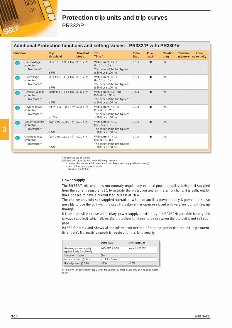
ABB SACE3/16
3
OV
UV
RP
RV
UF
OF
Additional Protection functions and setting values - PR332/P with PR330/V
Function Trip Threshold Trip Time Poss. Relation Thermal Zone threshold steps Time * Step excl. t=f(I) memory selectivity
Undervoltage U8= 0.5….0.95 x Un 0.01 x Un With current U < U8 0.1 s ■ t=k – – protection t8= 0.1 s....5 s Tolerance (1) The better of the two fi gures: ± 5% ± 20% or ± 100 ms
Overvoltage U9= 1.05….1.2 x Un 0.01 x Un With current U > U9 0.1 s ■ t=k – – protection t9= 0.1 s....5 s Tolerance (1) The better of the two fi gures: ± 5% ± 20% or ± 100 ms
Residual voltage U10= 0.1….0.4 x Un 0.05 x Un With current U0 > U10 0.5 s ■ t=k – – protection t10= 0.5 s....30 s Tolerance (1) The better of the two fi gures: ± 5% ± 10% or ± 100 ms
Reverse power P11= -0.3….-0.1 x Pn 0.02 x Pn With current P < P11 0.1 s ■ t=k – – protection t11= 0.5 s....25 s Tolerance (1) The better of the two fi gures: ± 10% ± 10% or ± 100 ms
Underfrequency f12= 0.90….0.99 x fn 0.01 x fn With current f < f12 0.1 s ■ t=k – – protection t9= 0.5 s....3 s Tolerance (1) The better of the two fi gures: ± 5% ± 10% or ± 100 ms
Overfrequency f13= 1.01….1.10 x fn 0.01 x fn With current f > f13 0.1 s ■ t=k – – protection t10= 0.5 s....3 s Tolerance (1) The better of the two fi gures: ± 5% ± 10% or ± 100 ms
* Referring to the electronics(1) These tolerances are valid in the following conditions: - self-supplied release at full power and/or auxiliary power supply (without start-up) - two- or three-phase power supply - trip time set ≥ 100 ms
Power supply
The PR332/P trip unit does not normally require any external power supplies, being self-supplied from the current sensors (CS): to activate the protection and ammeter functions, it is suffi cient for three phases to have a current load at least at 70 A.The unit ensures fully self-supplied operation. When an auxiliary power supply is present, it is also possible to use the unit with the circuit-breaker either open or closed with very low current fl owing through.It is also possible to use an auxiliary power supply provided by the PR030/B portable battery unit (always supplied), which allows the protection functions to be set when the trip unit is not self sup-plied.PR332/P stores and shows all the information needed after a trip (protection tripped, trip current, time, date). No auxiliary supply is required for this functionality.
(*) PR330/V can give power supply to the trip unit when a three phase voltage is equal or higher to 60V.
PR332/P PR330/D-M
Auxiliary power supply 24 V DC ± 20% from PR332/P(galvanically insulated) Maximum ripple 5% Inrush current @ 24V ~1 A for 5 ms Rated power @ 24V ~3 W +1 W
Protection trip units and trip curves PR332/P
X1_cap_3_01.indd 16X1_cap_3_01.indd 16 4-04-2007 9:51:214-04-2007 9:51:21
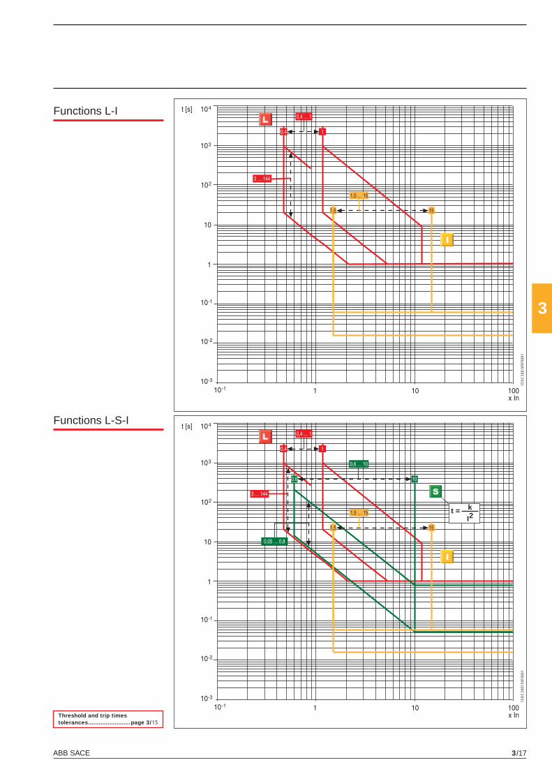
ABB SACE 3/17
3
t = k
I21S
DC
2001
09F0
001
1SD
C20
0110
F000
1
Functions L-I
Threshold and trip times tolerances ........................page 3/15
Functions L-S-I
X1_cap_3_01.indd 17X1_cap_3_01.indd 17 4-04-2007 9:51:224-04-2007 9:51:22
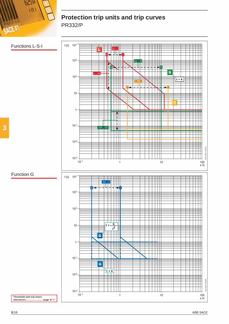
ABB SACE3/18
3
t = k
I2
t = k
t = k
1SD
C20
0111
F000
11S
DC
2001
12F0
001
Function G
Threshold and trip times tolerances ........................page 3/15
Functions L-S-I
Protection trip units and trip curves PR332/P
X1_cap_3_01.indd 18X1_cap_3_01.indd 18 4-04-2007 9:51:234-04-2007 9:51:23
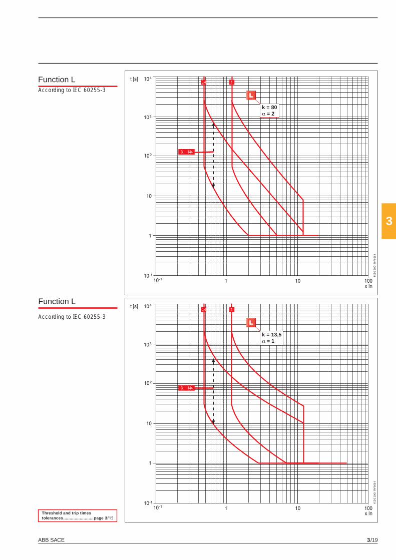
ABB SACE 3/19
3
k = 80α = 2
k = 13,5α = 1
1SD
C20
0120
F000
11S
DC
2001
19F0
001
Function L
Threshold and trip times tolerances ........................page 3/15
According to IEC 60255-3
Function L
According to IEC 60255-3
X1_cap_3_01.indd 19X1_cap_3_01.indd 19 4-04-2007 9:51:234-04-2007 9:51:23
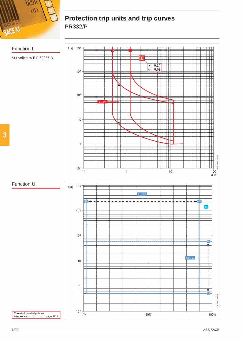
ABB SACE3/20
3
U
1SD
C20
0122
F000
1
k = 0,14α = 0,02
1SD
C20
0118
F000
1
Threshold and trip times tolerances ........................page 3/15
Function U
Protection trip units and trip curves PR332/P
Function L
According to IEC 60255-3
X1_cap_3_01.indd 20X1_cap_3_01.indd 20 4-04-2007 9:51:244-04-2007 9:51:24
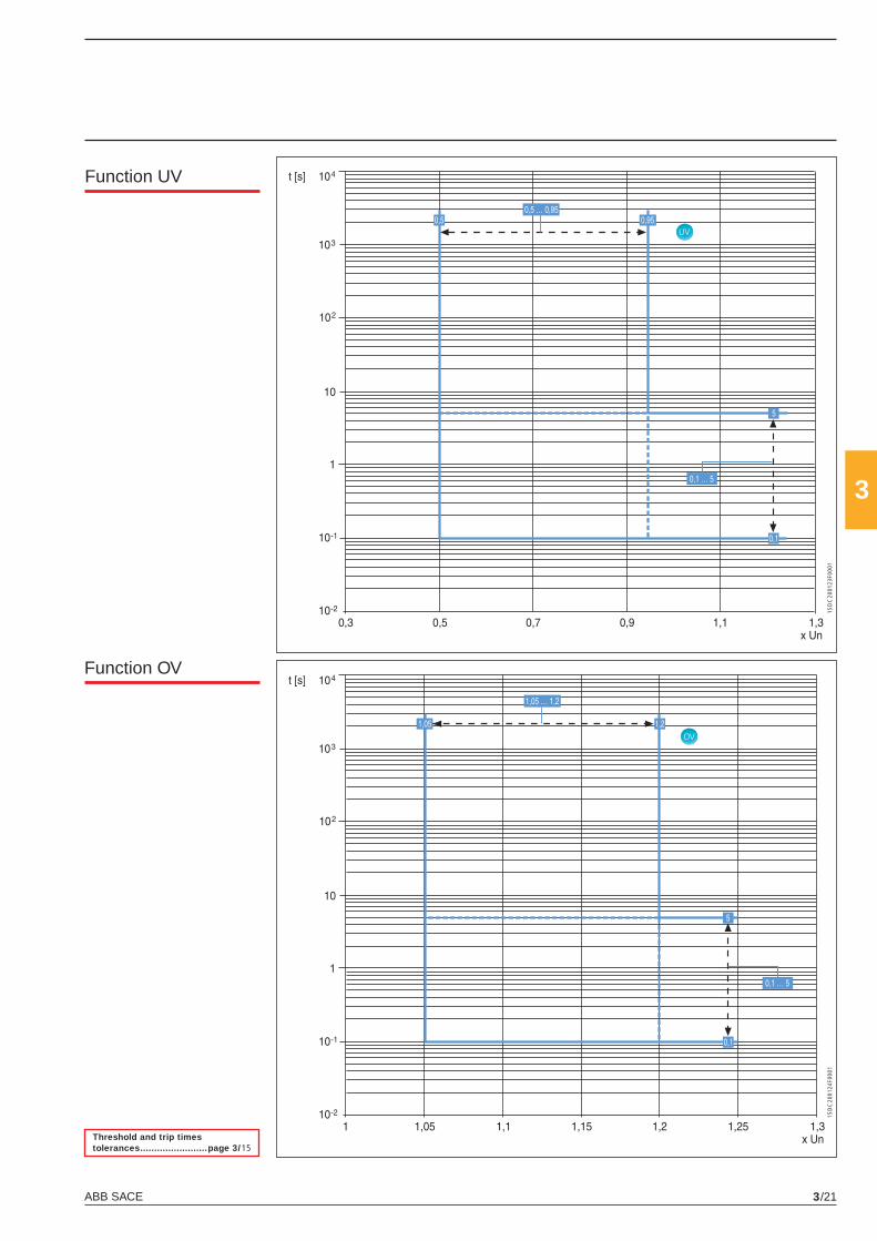
ABB SACE 3/21
3
UV
1SD
C20
0123
F000
1
OV
1SD
C20
0124
F000
1
Function UV
Function OV
Threshold and trip times tolerances ........................page 3/15
X1_cap_3_01.indd 21X1_cap_3_01.indd 21 4-04-2007 9:51:244-04-2007 9:51:24
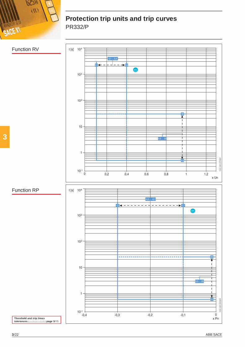
ABB SACE3/22
3
RP
1SD
C20
0126
F000
1
RV
1SD
C20
0125
F000
1
Function RP
Threshold and trip times tolerances ........................page 3/15
Function RV
Protection trip units and trip curves PR332/P
X1_cap_3_01.indd 22X1_cap_3_01.indd 22 4-04-2007 9:51:244-04-2007 9:51:24
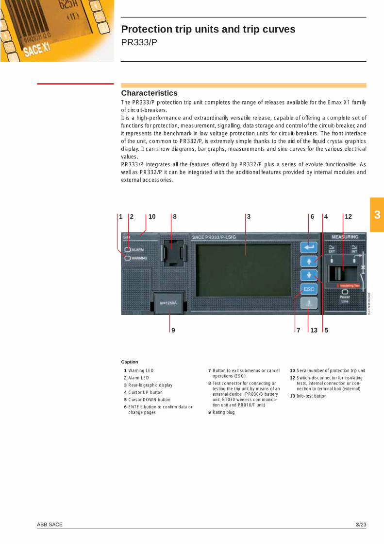
ABB SACE 3/23
310
7
2 31
5
48 6
9
12
13
1SD
C20
0538
F000
1
CharacteristicsThe PR333/P protection trip unit completes the range of releases available for the Emax X1 family of circuit-breakers.It is a high-performance and extraordinarily versatile release, capable of offering a complete set of functions for protection, measurement, signalling, data storage and control of the circuit-breaker, and it represents the benchmark in low voltage protection units for circuit-breakers. The front interface of the unit, common to PR332/P, is extremely simple thanks to the aid of the liquid crystal graphics display. It can show diagrams, bar graphs, measurements and sine curves for the various electrical values.PR333/P integrates all the features offered by PR332/P plus a series of evolute functionalitie. As well as PR332/P it can be integrated with the additional features provided by internal modules and external accessories.
Protection trip units and trip curves PR333/P
1 Warning LED
2 Alarm LED
3 Rear-lit graphic display
4 Cursor UP button
5 Cursor DOWN button
6 ENTER button to confi rm data or change pages
10 Serial number of protection trip unit
12 Switch-disconnector for insulating tests, internal connection or con-nection to terminal box (external)
13 Info-test button
Caption
7 Button to exit submenus or cancel operations (ESC)
8 Test connector for connecting or testing the trip unit by means of an external device (PR030/B battery unit, BT030 wireless communica-tion unit and PR010/T unit)
9 Rating plug
X1_cap_3_01.indd 23X1_cap_3_01.indd 23 4-04-2007 9:51:254-04-2007 9:51:25
ABB SACE3/24
3
In addition to PR332/P features, the following improvements are available:
Double selective short-circuit protection S
In addition to the standard S protection, PR333/P makes contemporarily available a second time-constant S protection (excludible) that allows two thresholds to be set independently achieving an accurate selectivity even under highly critical conditions.
Double earth fault protection G
While in PR332/P the user must choose among the implementation of G protection through internal current sensors (calculating the vectorial sum of currents) or external toroid (direct earth fault current measuring), PR333/P offers the exclusive feature of the contemporaneous management of both the confi guration, by means of two independent earth fault protections curves. The main application of this characteristic is simultaneous activation of restricted and unrestricted earth fault protection. See chapter 6 for details.
Directional short-circuit protection with adjustable delay D
The protection works in a similar way to the fi xed-time protection “S”, with the added ability to recognize the direction of the phases current during the fault period. The current direction makes it possible to determine whether the fault is on the supply or load side of the circuit-breaker. Particularly in ring distribution systems, this makes it possible to identify and disconnect the distribution segment where the fault has occurred, whilst keeping the rest of the installation running. If multiple PR332/P or PR333/P trip units are used, this protection can be associated with zone selectivity.
Protection functions The PR333/P trip unit offers the following protection functions:– overload (L),– selective short-circuit (S),– instantaneous short-circuit (I),– earth fault with adjustable delay (G),– protection against closing under short-circuit (MCR),– directional short-circuit with adjustable delay (D),– phase unbalance (U),– protection against overtemperature (OT),– load control (K),– undervoltage (UV),– overvoltage (OV),– residual voltage (RV),– reverse power (RP),– underfrequency (UF),– overfrequency (OF),– phase sequence (alarm only).
Protection trip units and trip curves PR333/P
X1_cap_3_01.indd 24X1_cap_3_01.indd 24 4-04-2007 9:51:274-04-2007 9:51:27
ABB SACE 3/25
3
Measurement functions
The PR333/P release provides a complete set of measurements:– Currents: three phases (L1, L2, L3), neutral (Ne) and earth fault– Voltage: phase-phase, phase-neutral and residual voltage– Power: active, reactive and apparent– Power factor– Frequency and peak factor, (Ip/Irms) – Energy: active, reactive, apparent, counter– Harmonics calculation: up to the 40th harmonic for frequency f = 50 Hz (waveform and module of
the harmonics displayed); up to the 35th for frequency f = 60Hz– Maintenance: number of operations, percentage of contact wear, opening data storage.
The PR333/P unit is able to provide the pattern of measurements for some values over an adjustable period of time P, such as: mean active power, maximum active power, maximum current, maximum voltage and minimum voltage. The last 24 P periods (adjustable from 5 to 120 min.) are stored in a non-volatile memory and displayed in a bar graph.
Other Functions
PR333/P integrates all the features (in terms of protection, measurement, signaling and communica-tion) described for PR332/P equipped with PR330/V.
Dual setting of protections
PR333/P can store an alternative set of all the protection parameters. This second set (set B) can replace, when needed, the default set (set A) by means of an external command. The command can be given typically when network confi guration is modifi ed, like when a parallel of incoming lines is closed or when an emergency source is present in the system, changing load capability and short-circuit levels.The set B can be activated by:– communication network, through PR330/D-M (i.e. when the changeover is scheduled);– directly from user interface of PR333/P– an adjustable time internal after closing of the circuit-breaker.
Zone selectivity function
The zone selectivity function allows the fault area to be insulated by segregating the system very rapidly only at the level closest to the fault, while leaving the rest of the installation running.This is done by connecting the releases together: the release nearest the fault is tripped instantly, sending a block signal to the other releases affected by the same fault. The zone selectivity function can be enabled if the fi xed-time curve has been selected and an auxiliary power supply is present. Zone selectivity can be applied with protections S and G or, alternatively, with protection D.
X1_cap_3_01.indd 25X1_cap_3_01.indd 25 4-04-2007 9:51:284-04-2007 9:51:28
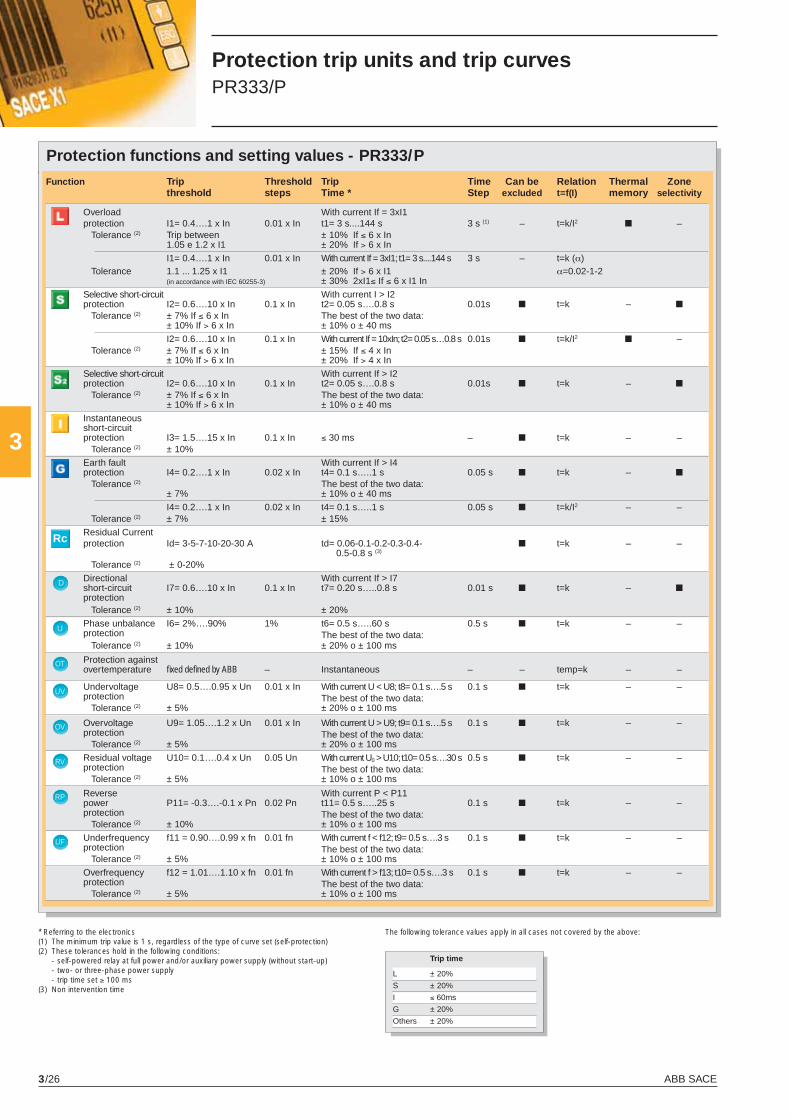
ABB SACE3/26
3
D
U
OT
UV
OV
RV
RP
Rc
UF
OF
Protection functions and setting values - PR333/P
* Referring to the electronics(1) The minimum trip value is 1 s, regardless of the type of curve set (self-protection)(2) These tolerances hold in the following conditions: - self-powered relay at full power and/or auxiliary power supply (without start-up) - two- or three-phase power supply - trip time set ≥ 100 ms(3) Non intervention time
The following tolerance values apply in all cases not covered by the above:
Protection trip units and trip curves PR333/P
Function Trip Threshold Trip Time Can be Relation Thermal Zone threshold steps Time * Step excluded t=f(I) memory selectivity
Overload With current If = 3xI1 protection I1= 0.4….1 x In 0.01 x In t1= 3 s....144 s 3 s (1) – t=k/I2 ■ – Tolerance (2) Trip between ± 10% If ≤ 6 x In 1.05 e 1.2 x I1 ± 20% If > 6 x In
I1= 0.4….1 x In 0.01 x In With current If = 3xI1; t1= 3 s....144 s 3 s – t=k (α) Tolerance 1.1 ... 1.25 x I1 ± 20% If > 6 x I1 α=0.02-1-2 (in accordance with IEC 60255-3) ± 30% 2xI1≤ If ≤ 6 x I1 In
Selective short-circuit With current I > I2 protection I2= 0.6….10 x In 0.1 x In t2= 0.05 s….0.8 s 0.01s ■ t=k – ■
Tolerance (2) ± 7% If ≤ 6 x In The best of the two data: ± 10% If > 6 x In ± 10% o ± 40 ms I2= 0.6….10 x In 0.1 x In With current If = 10xIn; t2= 0.05 s…0.8 s 0.01s ■ t=k/I2 ■ – Tolerance (2) ± 7% If ≤ 6 x In ± 15% If ≤ 4 x In ± 10% If > 6 x In ± 20% If > 4 x In
Selective short-circuit With current If > I2 protection I2= 0.6….10 x In 0.1 x In t2= 0.05 s….0.8 s 0.01s ■ t=k – ■
Tolerance (2) ± 7% If ≤ 6 x In The best of the two data: ± 10% If > 6 x In ± 10% o ± 40 ms Instantaneous short-circuit protection I3= 1.5….15 x In 0.1 x In ≤ 30 ms – ■ t=k – – Tolerance (2) ± 10% Earth fault With current If > I4 protection I4= 0.2….1 x In 0.02 x In t4= 0.1 s…..1 s 0.05 s ■ t=k – ■
Tolerance (2) The best of the two data: ± 7% ± 10% o ± 40 ms
I4= 0.2….1 x In 0.02 x In t4= 0.1 s…..1 s 0.05 s ■ t=k/I2 – – Tolerance (2) ± 7% ± 15%
Residual Current protection Id= 3-5-7-10-20-30 A td= 0.06-0.1-0.2-0.3-0.4- ■ t=k – – 0.5-0.8 s (3)
Tolerance (2) ± 0-20%
Directional With current If > I7 short-circuit I7= 0.6….10 x In 0.1 x In t7= 0.20 s…..0.8 s 0.01 s ■ t=k – ■ protection
Tolerance (2) ± 10% ± 20%
Phase unbalance I6= 2%….90% 1% t6= 0.5 s…..60 s 0.5 s ■ t=k – – protection The best of the two data: Tolerance (2) ± 10% ± 20% o ± 100 ms
Protection against overtemperature fi xed defi ned by ABB – Instantaneous – – temp=k – –
Undervoltage U8= 0.5….0.95 x Un 0.01 x In With current U < U8; t8= 0.1 s….5 s 0.1 s ■ t=k – – protection The best of the two data: Tolerance (2) ± 5% ± 20% o ± 100 ms
Overvoltage U9= 1.05….1.2 x Un 0.01 x In With current U > U9; t9= 0.1 s….5 s 0.1 s ■ t=k – – protection The best of the two data: Tolerance (2) ± 5% ± 20% o ± 100 ms
Residual voltage U10= 0.1….0.4 x Un 0.05 Un With current U0 > U10; t10= 0.5 s….30 s 0.5 s ■ t=k – – protection The best of the two data: Tolerance (2) ± 5% ± 10% o ± 100 ms
Reverse With current P < P11 power P11= -0.3….-0.1 x Pn 0.02 Pn t11= 0.5 s…..25 s 0.1 s ■ t=k – – protection The best of the two data: Tolerance (2) ± 10% ± 10% o ± 100 ms
Underfrequency f11 = 0.90….0.99 x fn 0.01 fn With current f < f12; t9= 0.5 s….3 s 0.1 s ■ t=k – – protection The best of the two data: Tolerance (2) ± 5% ± 10% o ± 100 ms
Overfrequency f12 = 1.01….1.10 x fn 0.01 fn With current f > f13; t10= 0.5 s….3 s 0.1 s ■ t=k – – protection The best of the two data: Tolerance (2) ± 5% ± 10% o ± 100 ms
Trip time
L ± 20%
S ± 20%
I ≤ 60ms
G ± 20%
Others ± 20%
X1_cap_3_01.indd 26X1_cap_3_01.indd 26 6-04-2007 8:51:446-04-2007 8:51:44
ABB SACE 3/27
3
Power supply
The PR333/P trip unit does not normally require any external power supplies, being self-supplied from the current sensors (CS): to activate the protection and ammeter functions, it is suffi cient for the three phases to have a current load at least at 70 A.The unit ensures fully self-supplied operation. When an auxiliary power supply is present, it is also possible to use the unit with the circuit-breaker either open or closed with very low current fl owing through.It is also possible to use an auxiliary power supply provided by the PR030/B portable battery unit (always supplied), which allows the protection functions to be set when the release is not self sup-plied.PR333/P stores and shows all the information needed after a trip (protection tripped, trip current, time, date). No auxiliary supply is required for this functionality.
PR330/V can give power supply to the release when a three-phase voltage is equal or higher to 60V.
PR333/P PR330/D-M
Auxiliary power supply 24 V DC ± 20% from PR333/P(galvanically insulated) Maximum ripple 5% Inrush current @ 24V ~1 A per 5 ms Rated power @ 24V ~3 W +1 W
X1_cap_3_01.indd 27X1_cap_3_01.indd 27 4-04-2007 9:51:304-04-2007 9:51:30
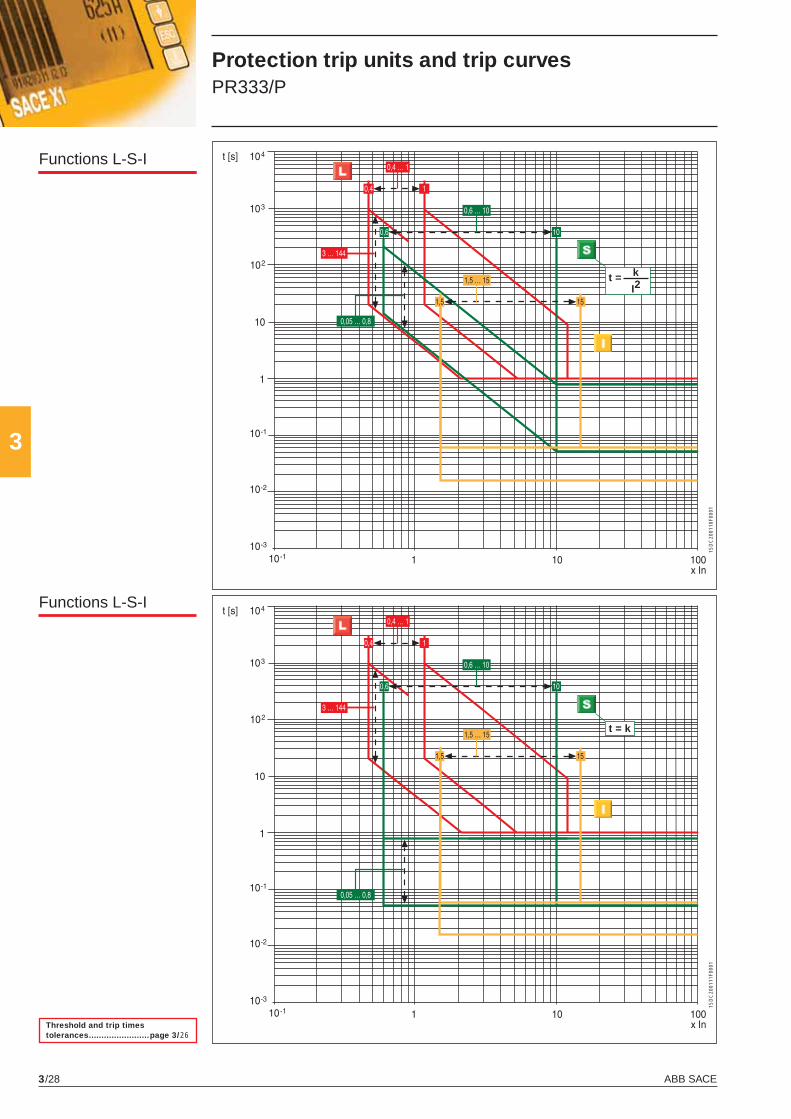
ABB SACE3/28
3
t = k
I2
t = k
1SD
C20
0110
F000
11S
DC
2001
11F0
001
Functions L-S-I
Threshold and trip times tolerances ........................page 3/26
Functions L-S-I
Protection trip units and trip curves PR333/P
X1_cap_3_01.indd 28X1_cap_3_01.indd 28 4-04-2007 9:51:314-04-2007 9:51:31
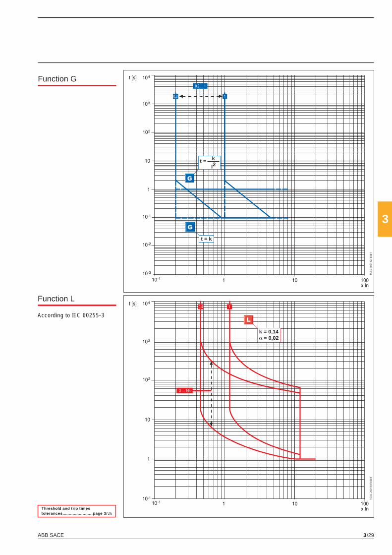
ABB SACE 3/29
3
k = 0,14α = 0,02
t = k
I2
t = k
1SD
C20
0112
F000
11S
DC
2001
18F0
001
Function G
Function L
Threshold and trip times tolerances ........................page 3/26
According to IEC 60255-3
X1_cap_3_01.indd 29X1_cap_3_01.indd 29 4-04-2007 9:51:314-04-2007 9:51:31
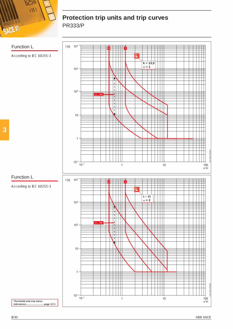
ABB SACE3/30
3
k = 80α = 2
k = 13,5α = 1
1SD
C20
0119
F000
11S
DC
2001
20F0
001
Function L
Function L
Threshold and trip times tolerances ........................page 3/26
According to IEC 60255-3
According to IEC 60255-3
Protection trip units and trip curves PR333/P
X1_cap_3_01.indd 30X1_cap_3_01.indd 30 4-04-2007 9:51:324-04-2007 9:51:32
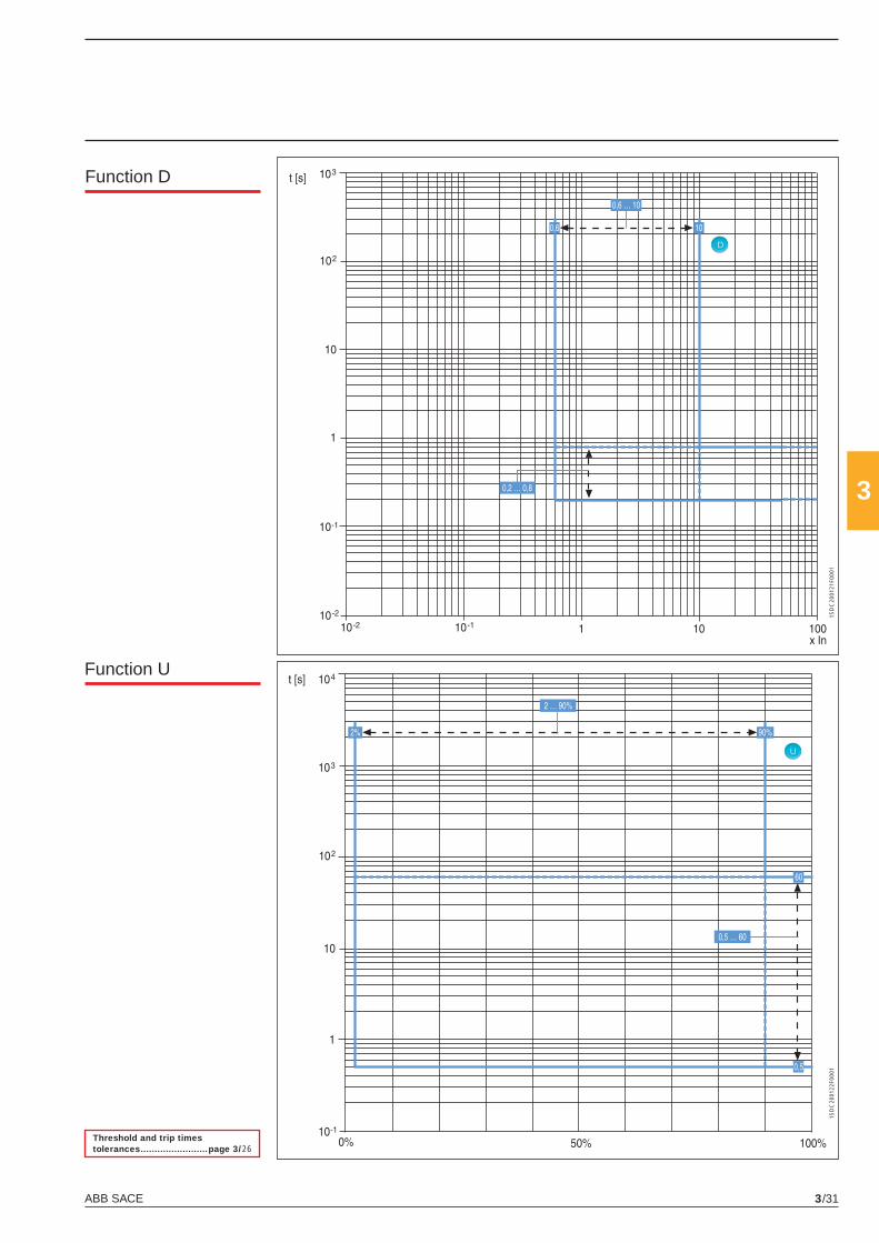
ABB SACE 3/31
3
D
U
1SD
C20
0121
F000
11S
DC
2001
22F0
001
Function D
Function U
Threshold and trip times tolerances ........................page 3/26
X1_cap_3_01.indd 31X1_cap_3_01.indd 31 4-04-2007 9:51:324-04-2007 9:51:32
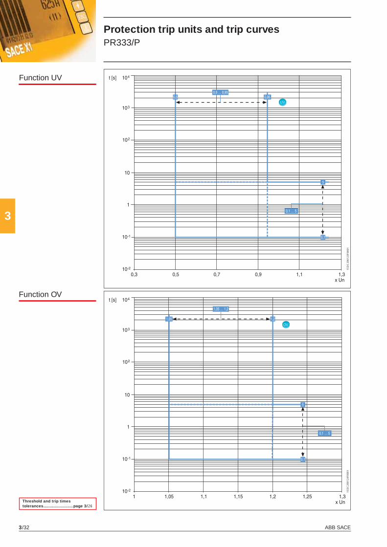
ABB SACE3/32
3
UV
OV
1SD
C20
0123
F000
11S
DC
2001
24F0
001
Function UV
Function OV
Threshold and trip times tolerances ........................page 3/26
Protection trip units and trip curves PR333/P
X1_cap_3_01.indd 32X1_cap_3_01.indd 32 4-04-2007 9:51:324-04-2007 9:51:32
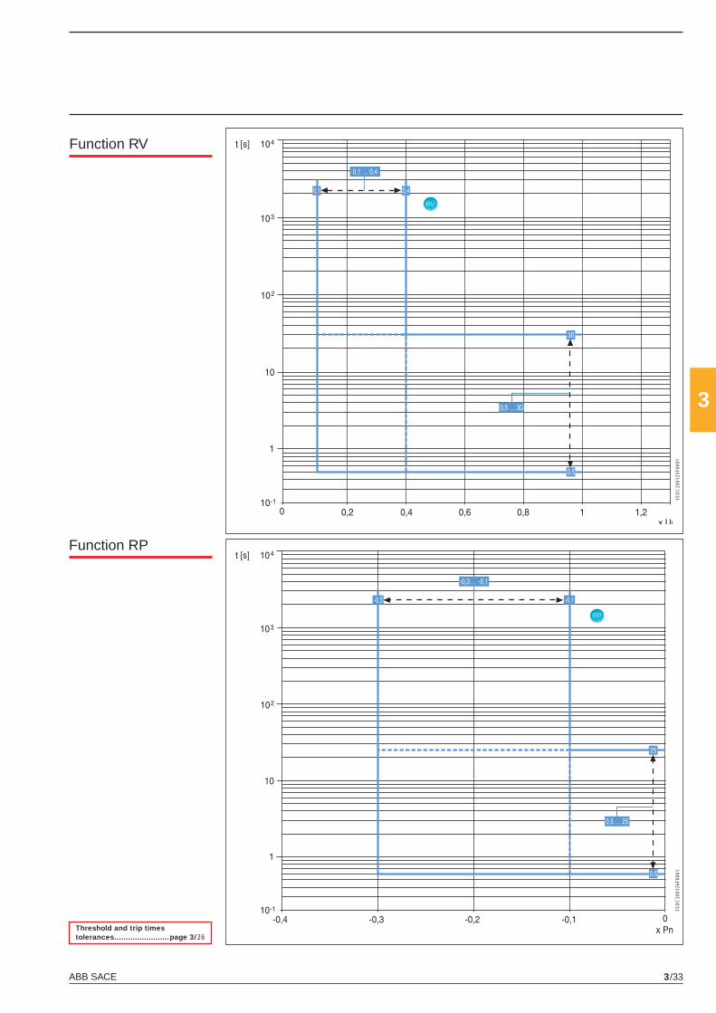
ABB SACE 3/33
3
RV
RP
1SD
C20
0125
F000
11S
DC
2001
26F0
001
Function RV
Function RP
Threshold and trip times tolerances ........................page 3/26
X1_cap_3_01.indd 33X1_cap_3_01.indd 33 4-04-2007 9:51:334-04-2007 9:51:33
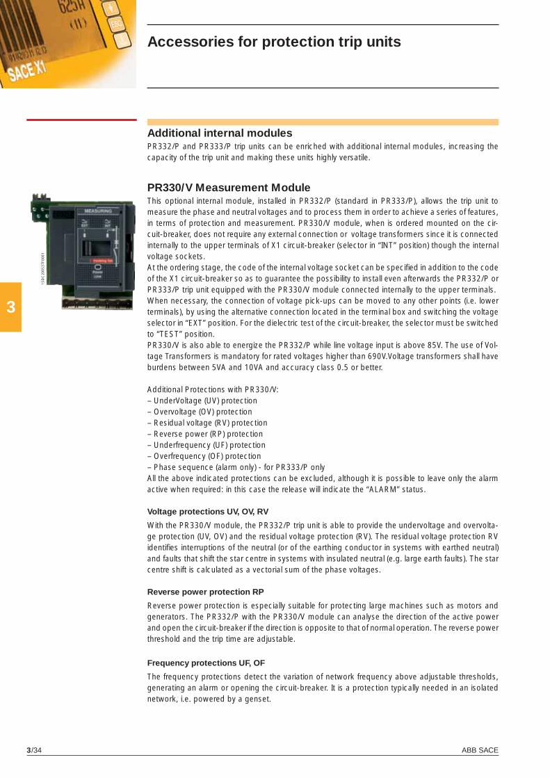
ABB SACE3/34
3
1SD
C20
0537
F000
1Accessories for protection trip units
Additional internal modulesPR332/P and PR333/P trip units can be enriched with additional internal modules, increasing the capacity of the trip unit and making these units highly versatile.
PR330/V Measurement ModuleThis optional internal module, installed in PR332/P (standard in PR333/P), allows the trip unit to measure the phase and neutral voltages and to process them in order to achieve a series of features, in terms of protection and measurement. PR330/V module, when is ordered mounted on the cir-cuit-breaker, does not require any external connection or voltage transformers since it is connected internally to the upper terminals of X1 circuit-breaker (selector in “INT” position) though the internal voltage sockets.At the ordering stage, the code of the internal voltage socket can be specifi ed in addition to the code of the X1 circuit-breaker so as to guarantee the possibility to install even afterwards the PR332/P or PR333/P trip unit equipped with the PR330/V module connected internally to the upper terminals.When necessary, the connection of voltage pick-ups can be moved to any other points (i.e. lower terminals), by using the alternative connection located in the terminal box and switching the voltage selector in “EXT” position. For the dielectric test of the circuit-breaker, the selector must be switched to “TEST” position.PR330/V is also able to energize the PR332/P while line voltage input is above 85V. The use of Vol-tage Transformers is mandatory for rated voltages higher than 690V.Voltage transformers shall have burdens between 5VA and 10VA and accuracy class 0.5 or better.
Additional Protections with PR330/V:– UnderVoltage (UV) protection– Overvoltage (OV) protection– Residual voltage (RV) protection– Reverse power (RP) protection– Underfrequency (UF) protection– Overfrequency (OF) protection– Phase sequence (alarm only) - for PR333/P onlyAll the above indicated protections can be excluded, although it is possible to leave only the alarm active when required: in this case the release will indicate the “ALARM” status.
Voltage protections UV, OV, RV
With the PR330/V module, the PR332/P trip unit is able to provide the undervoltage and overvolta-ge protection (UV, OV) and the residual voltage protection (RV). The residual voltage protection RV identifi es interruptions of the neutral (or of the earthing conductor in systems with earthed neutral) and faults that shift the star centre in systems with insulated neutral (e.g. large earth faults). The star centre shift is calculated as a vectorial sum of the phase voltages.
Reverse power protection RP
Reverse power protection is especially suitable for protecting large machines such as motors and generators. The PR332/P with the PR330/V module can analyse the direction of the active power and open the circuit-breaker if the direction is opposite to that of normal operation. The reverse power threshold and the trip time are adjustable.
Frequency protections UF, OF
The frequency protections detect the variation of network frequency above adjustable thresholds, generating an alarm or opening the circuit-breaker. It is a protection typically needed in an isolated network, i.e. powered by a genset.
X1_cap_3_01.indd 34X1_cap_3_01.indd 34 4-04-2007 9:51:334-04-2007 9:51:33
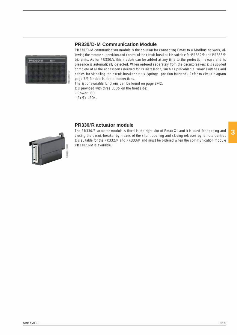
ABB SACE 3/35
3
1SD
C20
0539
F000
11S
DC
2006
00F0
001
PR330/D-M Communication ModulePR330/D-M communication module is the solution for connecting Emax to a Modbus network, al-lowing the remote supervision and control of the circuit-breaker. It is suitable for PR332/P and PR333/P trip units. As for PR330/V, this module can be added at any time to the protection release and its presence is automatically detected. When ordered separately from the circuitbreakers it is supplied complete of all the accessories needed for its installation, such as precabled auxiliary switches and cables for signalling the circuit-breaker status (springs, position inserted). Refer to circuit diagram page 7/9 for details about connections.The list of available functions can be found on page 3/42.It is provided with three LEDS on the front side:– Power LED– Rx/Tx LEDs.
PR330/R actuator moduleThe PR330/R actuator module is fi tted in the right slot of Emax X1 and it is used for opening and closing the circuit-breaker by means of the shunt opening and closing releases by remote control. It is suitable for the PR332/P and PR333/P and must be ordered when the communication module PR330/D-M is available.
X1_cap_3_01.indd 35X1_cap_3_01.indd 35 6-04-2007 8:52:236-04-2007 8:52:23

ABB SACE3/36
3
1SD
C20
0601
F000
1
1SD
C20
0602
F000
11S
DC
2006
03F0
001
Accessories for protection trip units
Additional external modulesPR331/P, PR332/P and PR333/P trip units can be enriched with additional external modules.
PR030/B power supply unitThis accessory, always supplied with the PR332/P and PR333/P range of trip units, makes it possible to read and confi gure the parameters of the unit whatever the status of the circuit breaker (open-closed, in test isolated or racked-in position, with or without auxiliary power supply).PR030/B is also needed for reading trip data if the trip occurred more than 48 hours earlier and the release was no longer powered.An internal electronic circuit supplies the unit for approximately 3 consecutive hours for the sole purpose of reading and confi guring data.In relation to the amount of use, battery life decreases if the PR030/B accessory is also used to perform the Trip test & Auto test.
Interface from front of HMI030 multimeterThis accessory, suitable for all protection releases, is designed for the installation on the front side of the switchboard. It consists of a graphic display where all the measurements and alarms/ events of the release are shown. The user can browse the measurements by using the navigation pushbut-tons, similarly to PR332/P, PR333/P, PR122/P and PR123/P. Thanks to the high precision level, the same of the protection releases, the device can replace the traditional instrumentation, without the need for current/voltage transformers. The HMI030 unit requires only a 24 V DC power supply, as it is connected directly to the protection release via a serial line.
BT030 Communication unitBT030 is a device to be connected on Test connector of PR331/P, PR332/P and PR333/P for Emax X1, as well as the PR121/P, PR122/P and PR123/P for Emax E1-E6 . It allows Bluetooth commu-nication among the Protection trip unit and a PDA or a Notebook with a Bluetooth port. BT030 can also be used with Tmax moulded-case circuit-breakers equipped with PR222DS/PD; this device is dedicated to the use with SD-Pocket application.BT030 can provide the power supply needed to energize itself and the protection release by means of a Li-ion rechargeable battery.
X1_cap_3_01.indd 36X1_cap_3_01.indd 36 4-04-2007 9:51:384-04-2007 9:51:38
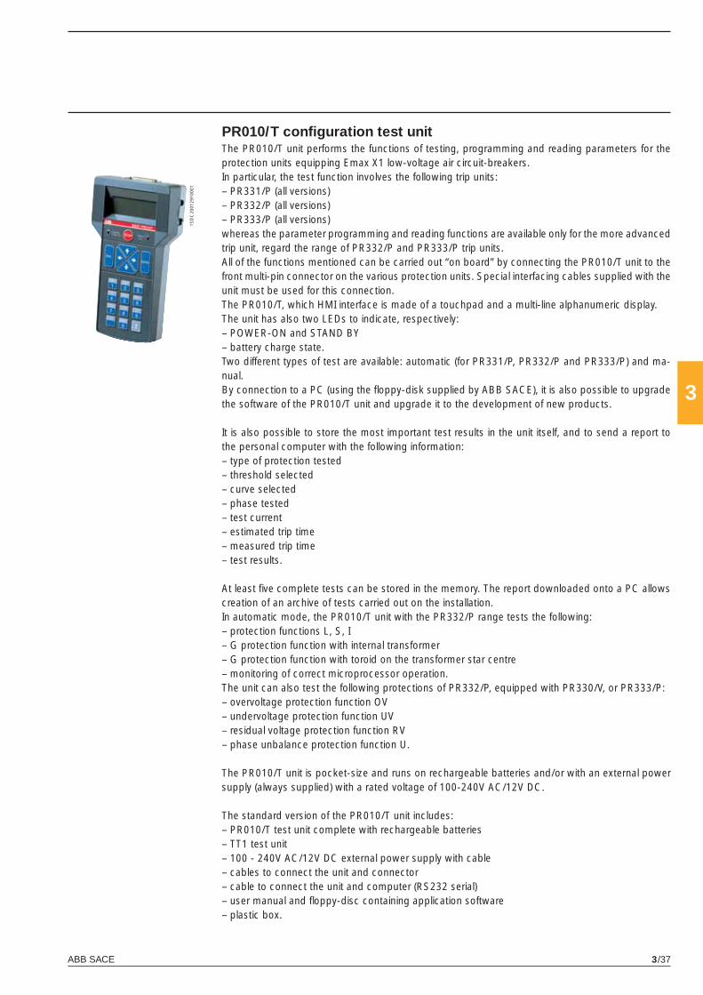
ABB SACE 3/37
3
1SD
C20
0129
F000
1
PR010/T confi guration test unitThe PR010/T unit performs the functions of testing, programming and reading parameters for the protection units equipping Emax X1 low-voltage air circuit-breakers.In particular, the test function involves the following trip units:– PR331/P (all versions)– PR332/P (all versions)– PR333/P (all versions)whereas the parameter programming and reading functions are available only for the more advanced trip unit, regard the range of PR332/P and PR333/P trip units.All of the functions mentioned can be carried out “on board” by connecting the PR010/T unit to the front multi-pin connector on the various protection units. Special interfacing cables supplied with the unit must be used for this connection.The PR010/T, which HMI interface is made of a touchpad and a multi-line alphanumeric display.The unit has also two LEDs to indicate, respectively:– POWER-ON and STAND BY– battery charge state.Two different types of test are available: automatic (for PR331/P, PR332/P and PR333/P) and ma-nual.By connection to a PC (using the fl oppy-disk supplied by ABB SACE), it is also possible to upgrade the software of the PR010/T unit and upgrade it to the development of new products.
It is also possible to store the most important test results in the unit itself, and to send a report to the personal computer with the following information:– type of protection tested– threshold selected– curve selected– phase tested– test current– estimated trip time– measured trip time– test results.
At least fi ve complete tests can be stored in the memory. The report downloaded onto a PC allows creation of an archive of tests carried out on the installation.In automatic mode, the PR010/T unit with the PR332/P range tests the following:– protection functions L, S, I– G protection function with internal transformer– G protection function with toroid on the transformer star centre– monitoring of correct microprocessor operation.The unit can also test the following protections of PR332/P, equipped with PR330/V, or PR333/P:– overvoltage protection function OV– undervoltage protection function UV– residual voltage protection function RV– phase unbalance protection function U.
The PR010/T unit is pocket-size and runs on rechargeable batteries and/or with an external power supply (always supplied) with a rated voltage of 100-240V AC/12V DC.
The standard version of the PR010/T unit includes:– PR010/T test unit complete with rechargeable batteries– TT1 test unit– 100 - 240V AC/12V DC external power supply with cable– cables to connect the unit and connector– cable to connect the unit and computer (RS232 serial)– user manual and fl oppy-disc containing application software– plastic box.
X1_cap_3_01.indd 37X1_cap_3_01.indd 37 4-04-2007 9:51:434-04-2007 9:51:43
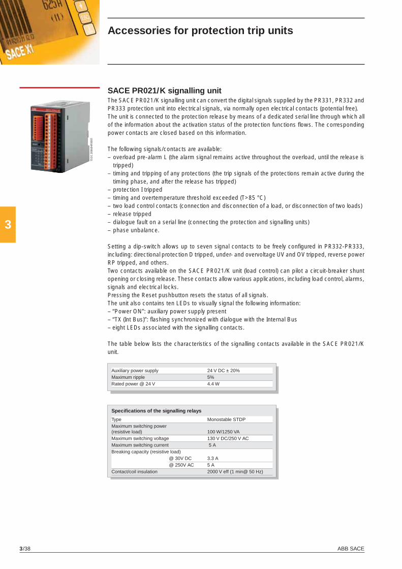
ABB SACE3/38
3
1SD
C20
0604
F000
1SACE PR021/K signalling unitThe SACE PR021/K signalling unit can convert the digital signals supplied by the PR331, PR332 and PR333 protection unit into electrical signals, via normally open electrical contacts (potential free).The unit is connected to the protection release by means of a dedicated serial line through which all of the information about the activation status of the protection functions fl ows. The corresponding power contacts are closed based on this information.
The following signals/contacts are available:– overload pre-alarm L (the alarm signal remains active throughout the overload, until the release is
tripped)– timing and tripping of any protections (the trip signals of the protections remain active during the
timing phase, and after the release has tripped)– protection I tripped– timing and overtemperature threshold exceeded (T>85 °C)– two load control contacts (connection and disconnection of a load, or disconnection of two loads)– release tripped– dialogue fault on a serial line (connecting the protection and signalling units)– phase unbalance.
Setting a dip-switch allows up to seven signal contacts to be freely confi gured in PR332-PR333, including: directional protection D tripped, under- and overvoltage UV and OV tripped, reverse power RP tripped, and others.Two contacts available on the SACE PR021/K unit (load control) can pilot a circuit-breaker shunt opening or closing release. These contacts allow various applications, including load control, alarms, signals and electrical locks.Pressing the Reset pushbutton resets the status of all signals.The unit also contains ten LEDs to visually signal the following information:– “Power ON”: auxiliary power supply present– “TX (Int Bus)”: fl ashing synchronized with dialogue with the Internal Bus– eight LEDs associated with the signalling contacts.
The table below lists the characteristics of the signalling contacts available in the SACE PR021/K unit.
Auxiliary power supply 24 V DC ± 20%Maximum ripple 5%Rated power @ 24 V 4.4 W
Specifi cations of the signalling relays
Type Monostable STDPMaximum switching power (resistive load) 100 W/1250 VA Maximum switching voltage 130 V DC/250 V ACMaximum switching current 5 A Breaking capacity (resistive load) @ 30V DC 3.3 A @ 250V AC 5 AContact/coil insulation 2000 V eff (1 min@ 50 Hz)
Accessories for protection trip units
X1_cap_3_01.indd 38X1_cap_3_01.indd 38 4-04-2007 9:51:444-04-2007 9:51:44
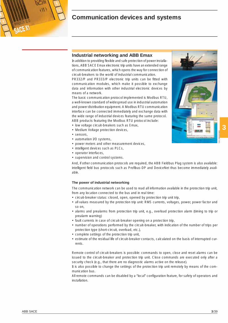
ABB SACE 3/39
3
1SD
C20
0303
F000
1
Communication devices and systems
Industrial networking and ABB EmaxIn addition to providing fl exible and safe protection of power installa-tions, ABB SACE Emax electronic trip units have an extended range of communication features, which opens the way for connection of circuit-breakers to the world of industrial communication.PR332/P and PR333/P electronic trip units can be fi tted with communication modules, which make it possible to exchange data and information with other industrial electronic devices by means of a network.The basic communication protocol implemented is Modbus RTU, a well-known standard of widespread use in industrial automation and power distribution equipment. A Modbus RTU communication interface can be connected immediately and exchange data with the wide range of industrial devices featuring the same protocol.ABB products featuring the Modbus RTU protocol include:• low voltage circuit-breakers such as Emax,• Medium Voltage protection devices,• sensors,• automation I/O systems,• power meters and other measurement devices,• intelligent devices such as PLCs,• operator interfaces,• supervision and control systems.
And, if other communication protocols are required, the ABB Fieldbus Plug system is also available: intelligent fi eld bus protocols such as Profi bus-DP and DeviceNet thus become immediately avail-able.
The power of industrial networking
The communication network can be used to read all information available in the protection trip unit, from any location connected to the bus and in real time:• circuit-breaker status: closed, open, opened by protection trip unit trip,• all values measured by the protection trip unit: RMS currents, voltages, power, power factor and
so on,• alarms and prealarms from protection trip unit, e.g., overload protection alarm (timing to trip or
prealarm warning)• fault currents in case of circuit-breaker opening on a protection trip,• number of operations performed by the circuit-breaker, with indication of the number of trips per
protection type (short-circuit, overload, etc.),• complete settings of the protection trip unit,• estimate of the residual life of circuit-breaker contacts, calculated on the basis of interrupted cur-
rents.
Remote control of circuit-breakers is possible: commands to open, close and reset alarms can be issued to the circuit-breaker and protection trip unit. Close commands are executed only after a security check (e.g., that there are no diagnostic alarms active on the release).It is also possible to change the settings of the protection trip unit remotely by means of the com-munication bus.All remote commands can be disabled by a “local” confi guration feature, for safety of operators and installation.
X1_cap_3_01.indd 39X1_cap_3_01.indd 39 4-04-2007 9:51:474-04-2007 9:51:47
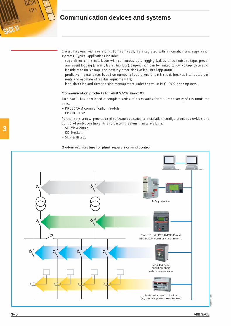
ABB SACE3/40
3
1SD
C20
0540
F000
1
Circuit-breakers with communication can easily be integrated with automation and supervision systems. Typical applications include:– supervision of the installation with continuous data logging (values of currents, voltage, power)
and event logging (alarms, faults, trip logs). Supervision can be limited to low voltage devices or include medium voltage and possibly other kinds of industrial apparatus;
– predictive maintenance, based on number of operations of each circuit-breaker, interrupted cur-rents and estimate of residual equipment life;
– load shedding and demand side management under control of PLC, DCS or computers.
Communication products for ABB SACE Emax X1
ABB SACE has developed a complete series of accessories for the Emax family of electronic trip units:– PR330/D-M communication module;– EP010 – FBP.
Furthermore, a new generation of software dedicated to installation, confi guration, supervision and control of protection trip units and circuit- breakers is now available:– SD-View 2000;– SD-Pocket;– SD-TestBus2.
System architecture for plant supervision and control
M.V. protection
Emax X1 with PR332/PR333 and PR330/D-M communication module
Moulded case circuit-breakers
with communication
Meter with communication (e.g. remote power measurement)
Communication devices and systems
X1_cap_3_01.indd 40X1_cap_3_01.indd 40 4-04-2007 9:51:484-04-2007 9:51:48
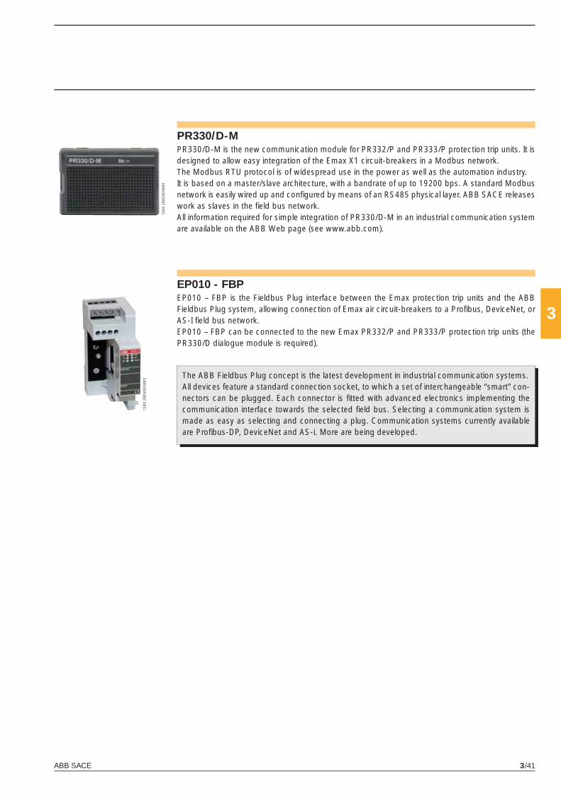
ABB SACE 3/41
3
1SD
C20
0305
F000
1
1SD
C20
0539
F000
1
PR330/D-MPR330/D-M is the new communication module for PR332/P and PR333/P protection trip units. It is designed to allow easy integration of the Emax X1 circuit-breakers in a Modbus network. The Modbus RTU protocol is of widespread use in the power as well as the automation industry. It is based on a master/slave architecture, with a bandrate of up to 19200 bps. A standard Modbus network is easily wired up and confi gured by means of an RS485 physical layer. ABB SACE releases work as slaves in the fi eld bus network.All information required for simple integration of PR330/D-M in an industrial communication system are available on the ABB Web page (see www.abb.com).
EP010 - FBPEP010 – FBP is the Fieldbus Plug interface between the Emax protection trip units and the ABB Fieldbus Plug system, allowing connection of Emax air circuit-breakers to a Profi bus, DeviceNet, or AS-I fi eld bus network.EP010 – FBP can be connected to the new Emax PR332/P and PR333/P protection trip units (the PR330/D dialogue module is required).
The ABB Fieldbus Plug concept is the latest development in industrial communication systems.All devices feature a standard connection socket, to which a set of interchangeable “smart” con-nectors can be plugged. Each connector is fi tted with advanced electronics implementing the communication interface towards the selected fi eld bus. Selecting a communication system is made as easy as selecting and connecting a plug. Communication systems currently available are Profi bus-DP, DeviceNet and AS-i. More are being developed.
X1_cap_3_01.indd 41X1_cap_3_01.indd 41 4-04-2007 9:51:494-04-2007 9:51:49
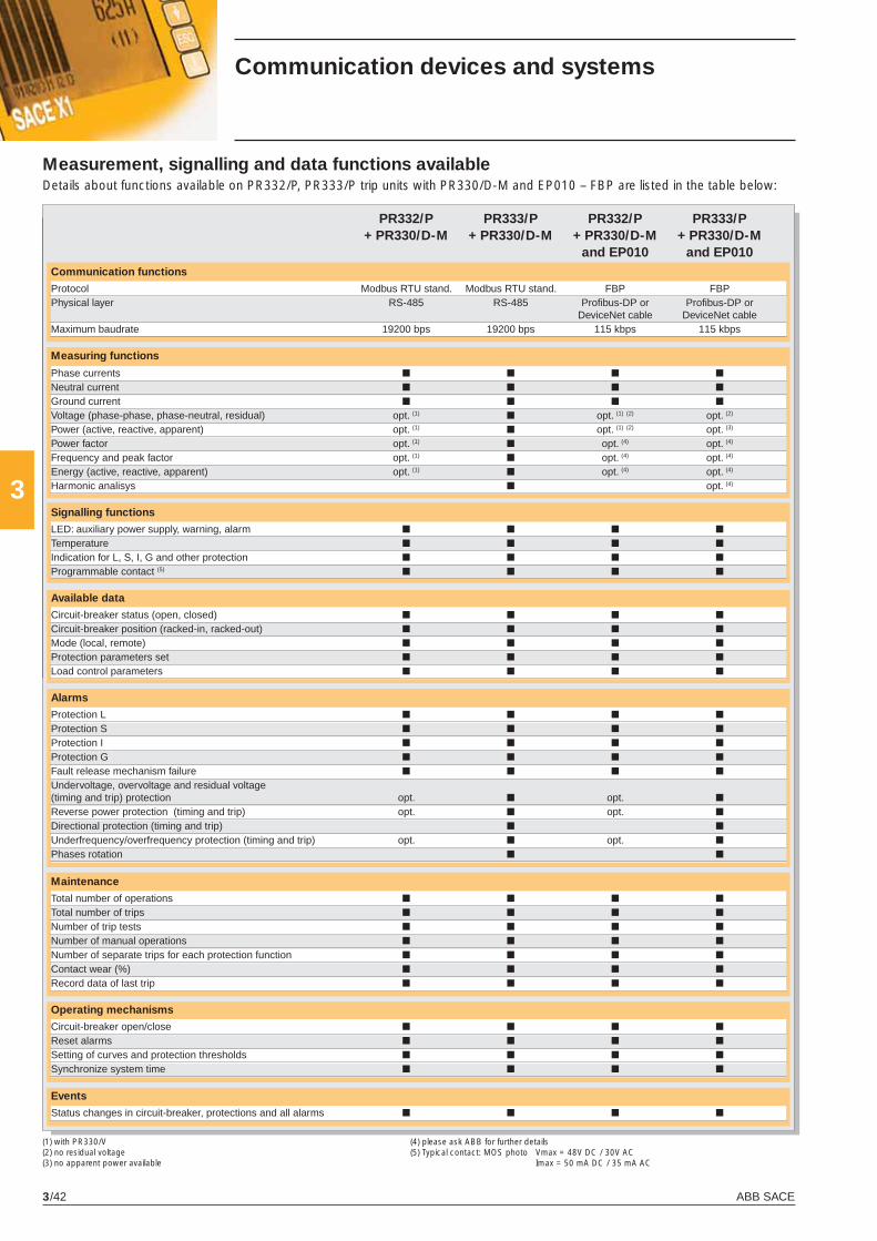
ABB SACE3/42
3
PR332/P PR333/P PR332/P PR333/P + PR330/D-M + PR330/D-M + PR330/D-M + PR330/D-M and EP010 and EP010Communication functions
Protocol Modbus RTU stand. Modbus RTU stand. FBP FBP Physical layer RS-485 RS-485 Profi bus-DP or Profi bus-DP or DeviceNet cable DeviceNet cableMaximum baudrate 19200 bps 19200 bps 115 kbps 115 kbps
Measuring functions
Phase currents ■ ■ ■ ■ Neutral current ■ ■ ■ ■ Ground current ■ ■ ■ ■ Voltage (phase-phase, phase-neutral, residual) opt. (1) ■ opt. (1) (2) opt. (2)
Power (active, reactive, apparent) opt. (1) ■ opt. (1) (2) opt. (3)
Power factor opt. (1) ■ opt. (4) opt. (4)
Frequency and peak factor opt. (1) ■ opt. (4) opt. (4)
Energy (active, reactive, apparent) opt. (1) ■ opt. (4) opt. (4)
Harmonic analisys ■ opt. (4)
Signalling functions
LED: auxiliary power supply, warning, alarm ■ ■ ■ ■
Temperature ■ ■ ■ ■
Indication for L, S, I, G and other protection ■ ■ ■ ■
Programmable contact (5) ■ ■ ■ ■
Available data
Circuit-breaker status (open, closed) ■ ■ ■ ■ Circuit-breaker position (racked-in, racked-out) ■ ■ ■ ■ Mode (local, remote) ■ ■ ■ ■ Protection parameters set ■ ■ ■ ■ Load control parameters ■ ■ ■ ■
Alarms
Protection L ■ ■ ■ ■ Protection S ■ ■ ■ ■ Protection I ■ ■ ■ ■ Protection G ■ ■ ■ ■ Fault release mechanism failure ■ ■ ■ ■ Undervoltage, overvoltage and residual voltage (timing and trip) protection opt. ■ opt. ■
Reverse power protection (timing and trip) opt. ■ opt. ■
Directional protection (timing and trip) ■ ■
Underfrequency/overfrequency protection (timing and trip) opt. ■ opt. ■
Phases rotation ■ ■
Maintenance
Total number of operations ■ ■ ■ ■ Total number of trips ■ ■ ■ ■ Number of trip tests ■ ■ ■ ■
Number of manual operations ■ ■ ■ ■ Number of separate trips for each protection function ■ ■ ■ ■
Contact wear (%) ■ ■ ■ ■ Record data of last trip ■ ■ ■ ■
Operating mechanisms
Circuit-breaker open/close ■ ■ ■ ■ Reset alarms ■ ■ ■ ■ Setting of curves and protection thresholds ■ ■ ■ ■ Synchronize system time ■ ■ ■ ■
Events
Status changes in circuit-breaker, protections and all alarms ■ ■ ■ ■
Measurement, signalling and data functions available Details about functions available on PR332/P, PR333/P trip units with PR330/D-M and EP010 – FBP are listed in the table below:
(1) with PR330/V (2) no residual voltage (3) no apparent power available
Communication devices and systems
(4) please ask ABB for further details (5) Typical contact: MOS photo Vmax = 48V DC / 30V AC Imax = 50 mA DC / 35 mA AC
X1_cap_3_01.indd 42X1_cap_3_01.indd 42 4-04-2007 9:51:514-04-2007 9:51:51
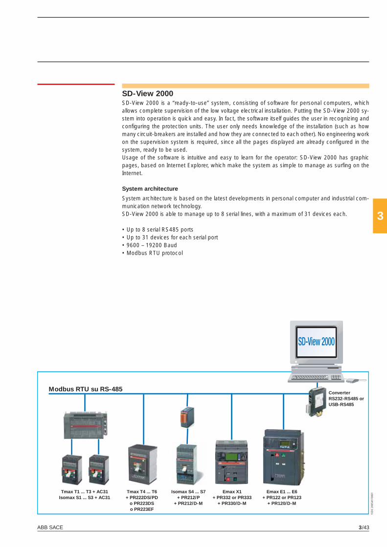
ABB SACE 3/43
3
1SD
C20
0541
F000
1
SD-View 2000SD-View 2000 is a “ready-to-use” system, consisting of software for personal computers, which allows complete supervision of the low voltage electrical installation. Putting the SD-View 2000 sy-stem into operation is quick and easy. In fact, the software itself guides the user in recognizing and confi guring the protection units. The user only needs knowledge of the installation (such as how many circuit-breakers are installed and how they are connected to each other). No engineering work on the supervision system is required, since all the pages displayed are already confi gured in the system, ready to be used.Usage of the software is intuitive and easy to learn for the operator: SD-View 2000 has graphic pages, based on Internet Explorer, which make the system as simple to manage as surfi ng on the Internet.
System architecture
System architecture is based on the latest developments in personal computer and industrial com-munication network technology.SD-View 2000 is able to manage up to 8 serial lines, with a maximum of 31 devices each.
• Up to 8 serial RS485 ports• Up to 31 devices for each serial port• 9600 – 19200 Baud• Modbus RTU protocol
Modbus RTU su RS-485
Tmax T1 ... T3 + AC31Isomax S1 ... S3 + AC31
Tmax T4 ... T6+ PR222DS/PD
o PR223DSo PR223EF
Emax X1+ PR332 or PR333
+ PR330/D-M
ConverterRS232-RS485 orUSB-RS485
Isomax S4 ... S7+ PR212/P
+ PR212/D-M
Emax E1 ... E6+ PR122 or PR123
+ PR120/D-M
X1_cap_3_01.indd 43X1_cap_3_01.indd 43 4-04-2007 9:51:524-04-2007 9:51:52
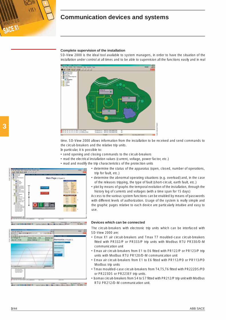
ABB SACE3/44
3
1SD
C20
0307
F000
1
1SD
C20
0308
F000
11S
DC
2003
09F0
001
Devices which can be connected
The circuit-breakers with electronic trip units which can be interfaced with SD-View 2000 are:• Emax X1 air circuit-breakers and Tmax T7 moulded-case circuit-breakers
fi tted with PR332/P or PR333/P trip units with Modbus RTU PR330/D-M communication unit
• Emax air circuit-breakers from E1 to E6 fi tted with PR122/P or PR123/P trip units with Modbus RTU PR120/D-M communication unit
• Emax air circuit-breakers from E1 to E6 fi tted with PR112/PD or PR113/PD Modbus trip units
• Tmax moulded-case circuit-breakers from T4,T5,T6 fi tted with PR222DS/PD or PR223DS or PR223EF trip units.
• Isomax circuit-breakers from S4 to S7 fi tted with PR212/P trip unit with Modbus RTU PR212/D-M communication unit.
Complete supervision of the installationSD-View 2000 is the ideal tool available to system managers, in order to have the situation of the installation under control at all times and to be able to supervision all the functions easily and in real
time. SD-View 2000 allows information from the installation to be received and send commands to the circuit-breakers and the relative trip units.In particular, it is possible to:• send opening and closing commands to the circuit-breakers• read the electrical installation values (current, voltage, power factor, etc.)• read and modify the trip characteristics of the protection units
• determine the status of the apparatus (open, closed, number of operations, trip for fault, etc.)
• determine the abnormal operating situations (e.g. overload) and, in the case of the releases tripping, the type of fault (short-circuit, earth fault, etc.)
• plot by means of graphs the temporal evolution of the installation, through the history log of currents and voltages (with a time span for 15 days)
Access to the various system functions can be enabled by means of passwords with different levels of authorization. Usage of the system is really simple and the graphic pages relative to each device are particularly intuitive and easy to use.
Communication devices and systems
X1_cap_3_01.indd 44X1_cap_3_01.indd 44 4-04-2007 9:51:534-04-2007 9:51:53
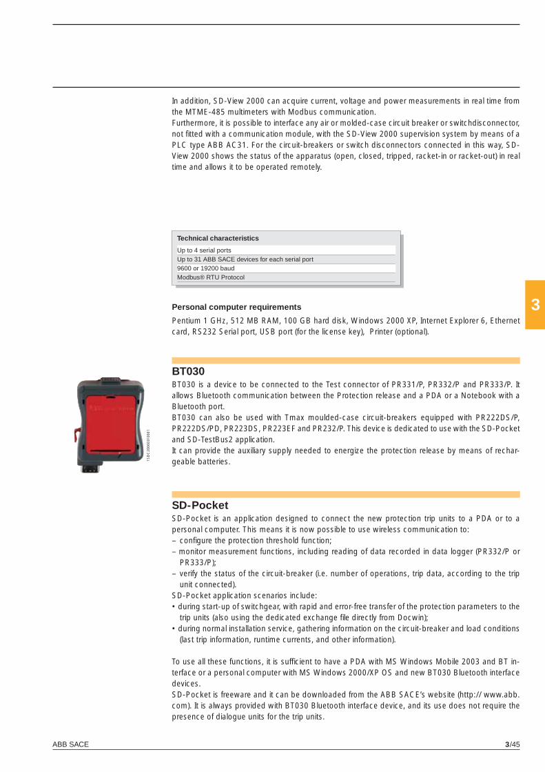
ABB SACE 3/45
3
1SD
C20
0603
F000
1
SD-PocketSD-Pocket is an application designed to connect the new protection trip units to a PDA or to a personal computer. This means it is now possible to use wireless communication to:– confi gure the protection threshold function;– monitor measurement functions, including reading of data recorded in data logger (PR332/P or
PR333/P);– verify the status of the circuit-breaker (i.e. number of operations, trip data, according to the trip
unit connected).SD-Pocket application scenarios include:• during start-up of switchgear, with rapid and error-free transfer of the protection parameters to the
trip units (also using the dedicated exchange fi le directly from Docwin);• during normal installation service, gathering information on the circuit-breaker and load conditions
(last trip information, runtime currents, and other information).
To use all these functions, it is suffi cient to have a PDA with MS Windows Mobile 2003 and BT in-terface or a personal computer with MS Windows 2000/XP OS and new BT030 Bluetooth interface devices.SD-Pocket is freeware and it can be downloaded from the ABB SACE’s website (http:// www.abb.com). It is always provided with BT030 Bluetooth interface device, and its use does not require the presence of dialogue units for the trip units.
Personal computer requirements
Pentium 1 GHz, 512 MB RAM, 100 GB hard disk, Windows 2000 XP, Internet Explorer 6, Ethernet card, RS232 Serial port, USB port (for the license key), Printer (optional).
Technical characteristics
Up to 4 serial portsUp to 31 ABB SACE devices for each serial port9600 or 19200 baudModbus® RTU Protocol
In addition, SD-View 2000 can acquire current, voltage and power measurements in real time from the MTME-485 multimeters with Modbus communication.Furthermore, it is possible to interface any air or molded-case circuit breaker or switchdisconnector, not fi tted with a communication module, with the SD-View 2000 supervision system by means of a PLC type ABB AC31. For the circuit-breakers or switch disconnectors connected in this way, SD-View 2000 shows the status of the apparatus (open, closed, tripped, racket-in or racket-out) in real time and allows it to be operated remotely.
BT030BT030 is a device to be connected to the Test connector of PR331/P, PR332/P and PR333/P. It allows Bluetooth communication between the Protection release and a PDA or a Notebook with a Bluetooth port.BT030 can also be used with Tmax moulded-case circuit-breakers equipped with PR222DS/P, PR222DS/PD, PR223DS, PR223EF and PR232/P. This device is dedicated to use with the SD-Pocket and SD-TestBus2 application.It can provide the auxiliary supply needed to energize the protection release by means of rechar-geable batteries.
X1_cap_3_01.indd 45X1_cap_3_01.indd 45 4-04-2007 9:51:554-04-2007 9:51:55
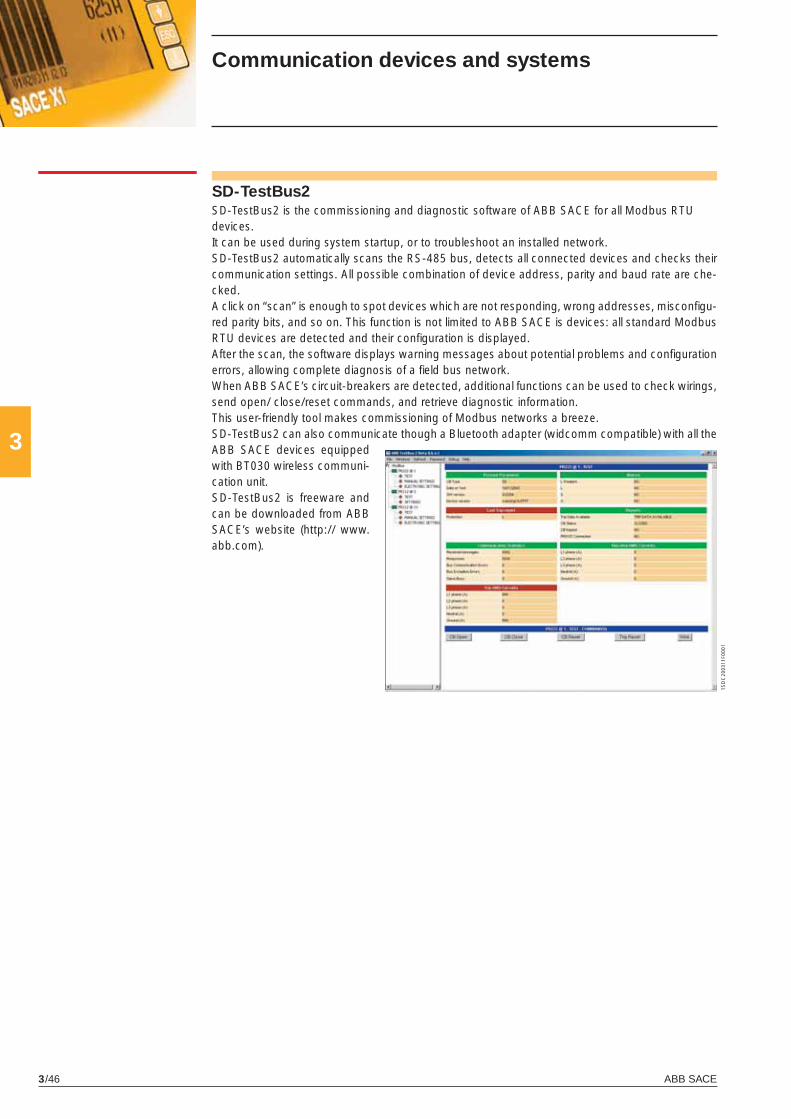
ABB SACE3/46
3
1SD
C20
0311
F000
1
SD-TestBus2SD-TestBus2 is the commissioning and diagnostic software of ABB SACE for all Modbus RTUdevices.It can be used during system startup, or to troubleshoot an installed network. SD-TestBus2 automatically scans the RS-485 bus, detects all connected devices and checks their communication settings. All possible combination of device address, parity and baud rate are che-cked.A click on “scan” is enough to spot devices which are not responding, wrong addresses, misconfi gu-red parity bits, and so on. This function is not limited to ABB SACE is devices: all standard Modbus RTU devices are detected and their confi guration is displayed.After the scan, the software displays warning messages about potential problems and confi guration errors, allowing complete diagnosis of a fi eld bus network.When ABB SACE’s circuit-breakers are detected, additional functions can be used to check wirings, send open/ close/reset commands, and retrieve diagnostic information.This user-friendly tool makes commissioning of Modbus networks a breeze. SD-TestBus2 can also communicate though a Bluetooth adapter (widcomm compatible) with all the ABB SACE devices equipped with BT030 wireless communi-cation unit.SD-TestBus2 is freeware and can be downloaded from ABB SACE’s website (http:// www.abb.com).
Communication devices and systems
X1_cap_3_01.indd 46X1_cap_3_01.indd 46 4-04-2007 9:51:574-04-2007 9:51:57
X1_cap_4_00.indd 2X1_cap_4_00.indd 2 4-04-2007 9:52:374-04-2007 9:52:37
4
ABB SACE 4/1
Accessories
Contents
Functions of the accessories .......................................................................................... 4/2
Accessories supplied as standard .................................................................................. 4/3
Accessories supplied on request ................................................................................... 4/4
Shunt opening and closing releases .............................................................................. 4/5
Undervoltage release ....................................................................................................... 4/7
Geared motor for the automatic charging of the closing springs ............................... 4/8
Signalling of electronic trip units tripped ....................................................................... 4/8
Auxiliary contacts .............................................................................................................. 4/9
Transformers and operation counters ............................................................................ 4/11
Mechanical safety locks .................................................................................................. 4/12
Transparent protective covers ........................................................................................ 4/13
Sliding contact locks ........................................................................................................ 4/14
Interlock between circuit-breakers ................................................................................ 4/15
Automatic transfer switch - ATS010 .............................................................................. 4/16
X1_cap_4_00.indd 3X1_cap_4_00.indd 3 4-04-2007 9:52:404-04-2007 9:52:40
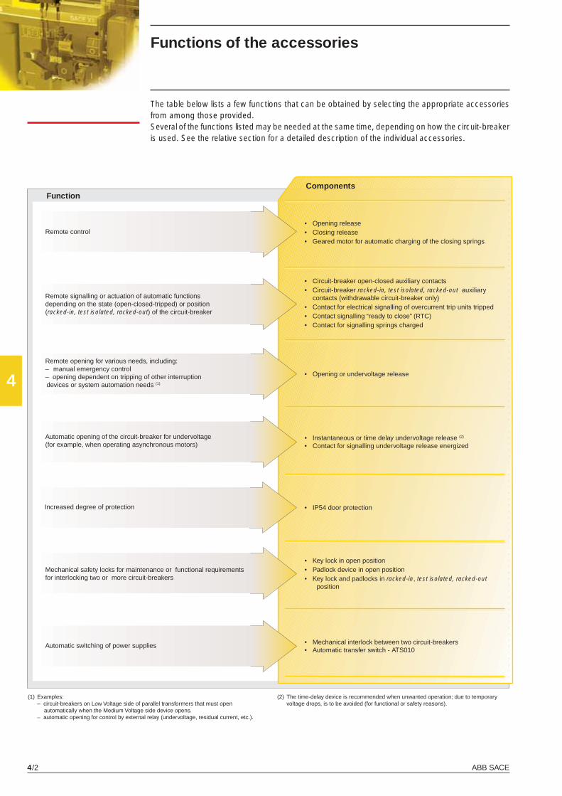
ABB SACE4/2
4
Functions of the accessories
The table below lists a few functions that can be obtained by selecting the appropriate accessories from among those provided.Several of the functions listed may be needed at the same time, depending on how the circuit-breaker is used. See the relative section for a detailed description of the individual accessories.
FunctionComponents
Automatic opening of the circuit-breaker for undervoltage(for example, when operating asynchronous motors)
• Opening release• Closing release• Geared motor for automatic charging of the closing springs
• Circuit-breaker open-closed auxiliary contacts• Circuit-breaker racked-in, test isolated, racked-out auxiliary
contacts (withdrawable circuit-breaker only)• Contact for electrical signalling of overcurrent trip units tripped• Contact signalling “ready to close” (RTC)• Contact for signalling springs charged
• Opening or undervoltage release
• Instantaneous or time delay undervoltage release (2)
• Contact for signalling undervoltage release energized
• Mechanical interlock between two circuit-breakers• Automatic transfer switch - ATS010
• Key lock in open position • Padlock device in open position• Key lock and padlocks in racked-in, test isolated, racked-out
position
Remote control
Remote signalling or actuation of automatic functions depending on the state (open-closed-tripped) or position (racked-in, test isolated, racked-out) of the circuit-breaker
Mechanical safety locks for maintenance or functional requirements for interlocking two or more circuit-breakers
Automatic switching of power supplies
Increased degree of protection
Remote opening for various needs, including: – manual emergency control – opening dependent on tripping of other interruption devices or system automation needs (1)
• IP54 door protection
(1) Examples: – circuit-breakers on Low Voltage side of parallel transformers that must open
automatically when the Medium Voltage side device opens. – automatic opening for control by external relay (undervoltage, residual current, etc.).
(2) The time-delay device is recommended when unwanted operation; due to temporary voltage drops, is to be avoided (for functional or safety reasons).
X1_cap_4_01.indd 2X1_cap_4_01.indd 2 4-04-2007 9:14:034-04-2007 9:14:03
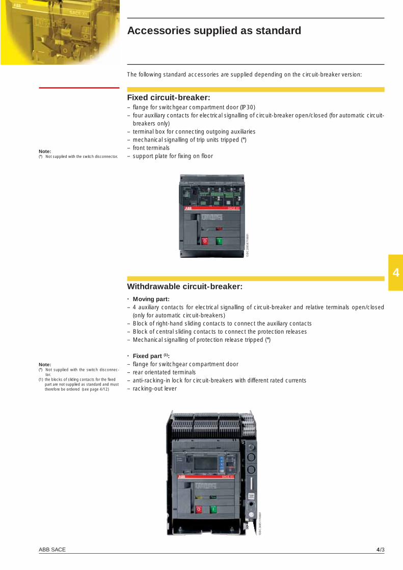
ABB SACE 4/3
4
1SD
C20
0507
F000
1
1SD
C20
0511
F000
1
Accessories supplied as standard
Fixed circuit-breaker:– fl ange for switchgear compartment door (IP30)– four auxiliary contacts for electrical signalling of circuit-breaker open/closed (for automatic circuit-
breakers only)– terminal box for connecting outgoing auxiliaries– mechanical signalling of trip units tripped (*)– front terminals– support plate for fi xing on fl oor
The following standard accessories are supplied depending on the circuit-breaker version:
Withdrawable circuit-breaker:· Moving part:– 4 auxiliary contacts for electrical signalling of circuit-breaker and relative terminals open/closed
(only for automatic circuit-breakers) – Block of right-hand sliding contacts to connect the auxiliary contacts– Block of central sliding contacts to connect the protection releases– Mechanical signalling of protection release tripped (*)
· Fixed part (1):– fl ange for switchgear compartment door– rear orientated terminals– anti-racking-in lock for circuit-breakers with different rated currents– racking-out lever
Note:(*) Not supplied with the switch disconnector.
Note:(*) Not supplied with the switch disconnec-
tor.(1) the blocks of sliding contacts for the fi xed
part are not supplied as standard and must therefore be ordered (see page 4/12)
X1_cap_4_01.indd 3X1_cap_4_01.indd 3 4-04-2007 9:14:054-04-2007 9:14:05
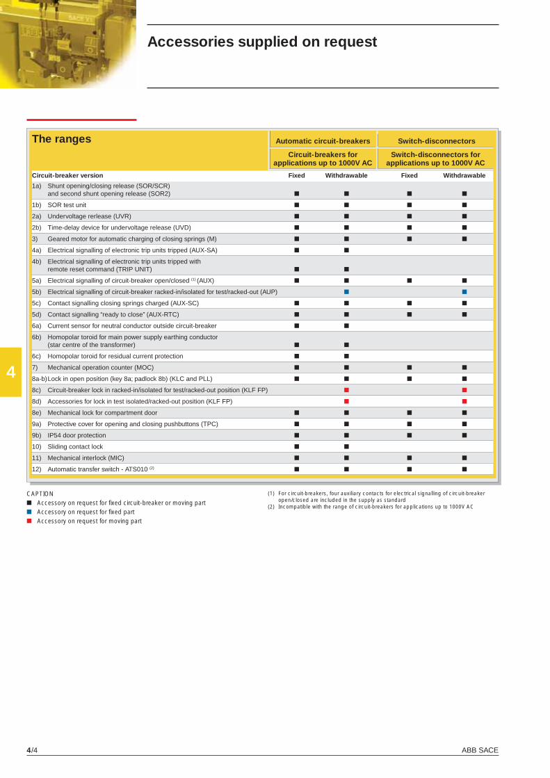
ABB SACE4/4
4
■ ■
■
Accessories supplied on request
The ranges Automatic circuit-breakers
Circuit-breakers for applications up to 1000V AC
Switch-disconnectors
Switch-disconnectors for applications up to 1000V AC
(1) For circuit-breakers, four auxiliary contacts for electrical signalling of circuit-breaker open/closed are included in the supply as standard
(2) Incompatible with the range of circuit-breakers for applications up to 1000V AC
CAPTION Accessory on request for fi xed circuit-breaker or moving part Accessory on request for fi xed part Accessory on request for moving part
Circuit-breaker version Fixed Withdrawable Fixed Withdrawable
1a) Shunt opening/closing release (SOR/SCR) and second shunt opening release (SOR2) ■ ■ ■ ■
1b) SOR test unit ■ ■ ■ ■
2a) Undervoltage rerlease (UVR) ■ ■ ■ ■
2b) Time-delay device for undervoltage release (UVD) ■ ■ ■ ■
3) Geared motor for automatic charging of closing springs (M) ■ ■ ■ ■
4a) Electrical signalling of electronic trip units tripped (AUX-SA) ■ ■
4b) Electrical signalling of electronic trip units tripped with remote reset command (TRIP UNIT) ■ ■
5a) Electrical signalling of circuit-breaker open/closed (1) (AUX) ■ ■ ■ ■
5b) Electrical signalling of circuit-breaker racked-in/isolated for test/racked-out (AUP) ■ ■
5c) Contact signalling closing springs charged (AUX-SC) ■ ■ ■ ■
5d) Contact signalling “ready to close” (AUX-RTC) ■ ■ ■ ■
6a) Current sensor for neutral conductor outside circuit-breaker ■ ■
6b) Homopolar toroid for main power supply earthing conductor (star centre of the transformer) ■ ■
6c) Homopolar toroid for residual current protection ■ ■
7) Mechanical operation counter (MOC) ■ ■ ■ ■
8a-b) Lock in open position (key 8a; padlock 8b) (KLC and PLL) ■ ■ ■ ■
8c) Circuit-breaker lock in racked-in/isolated for test/racked-out position (KLF FP) ■ ■
8d) Accessories for lock in test isolated/racked-out position (KLF FP) ■ ■
8e) Mechanical lock for compartment door ■ ■ ■ ■
9a) Protective cover for opening and closing pushbuttons (TPC) ■ ■ ■ ■
9b) IP54 door protection ■ ■ ■ ■
10) Sliding contact lock ■ ■
11) Mechanical interlock (MIC) ■ ■ ■ ■
12) Automatic transfer switch - ATS010 (2) ■ ■ ■ ■
X1_cap_4_01.indd 4X1_cap_4_01.indd 4 4-04-2007 9:14:084-04-2007 9:14:08
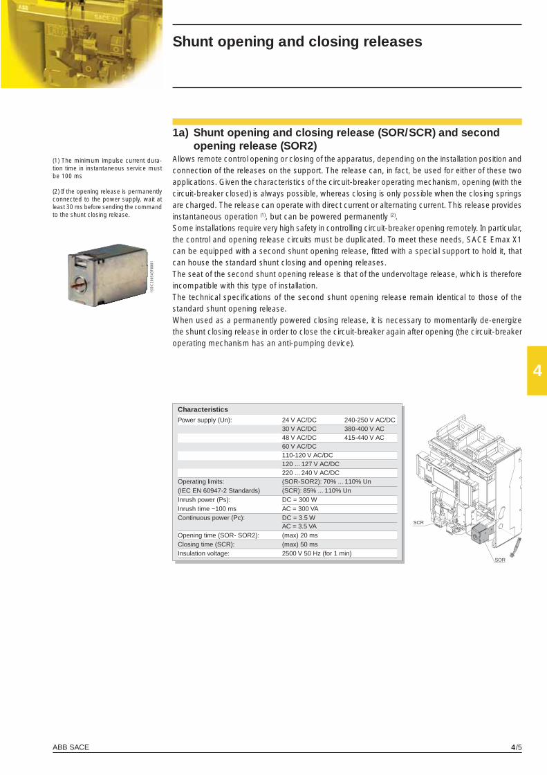
ABB SACE 4/5
4
1SD
C20
0543
F000
1
SCR
SOR
Shunt opening and closing releases
(1) The minimum impulse current dura-tion time in instantaneous service must be 100 ms
(2) If the opening release is permanently connected to the power supply, wait at least 30 ms before sending the command to the shunt closing release.
1a) Shunt opening and closing release (SOR/SCR) and second opening release (SOR2)
Allows remote control opening or closing of the apparatus, depending on the installation position and connection of the releases on the support. The release can, in fact, be used for either of these two applications. Given the characteristics of the circuit-breaker operating mechanism, opening (with the circuit-breaker closed) is always possible, whereas closing is only possible when the closing springs are charged. The release can operate with direct current or alternating current. This release provides instantaneous operation (1), but can be powered permanently (2).Some installations require very high safety in controlling circuit-breaker opening remotely. In particular, the control and opening release circuits must be duplicated. To meet these needs, SACE Emax X1 can be equipped with a second shunt opening release, fi tted with a special support to hold it, that can house the standard shunt closing and opening releases.The seat of the second shunt opening release is that of the undervoltage release, which is therefore incompatible with this type of installation. The technical specifi cations of the second shunt opening release remain identical to those of the standard shunt opening release.When used as a permanently powered closing release, it is necessary to momentarily de-energize the shunt closing release in order to close the circuit-breaker again after opening (the circuit-breaker operating mechanism has an anti-pumping device).
Characteristics
Power supply (Un): 24 V AC/DC 240-250 V AC/DC 30 V AC/DC 380-400 V AC 48 V AC/DC 415-440 V AC 60 V AC/DC 110-120 V AC/DC 120 ... 127 V AC/DC 220 ... 240 V AC/DC Operating limits: (SOR-SOR2): 70% ... 110% Un(IEC EN 60947-2 Standards) (SCR): 85% ... 110% UnInrush power (Ps): DC = 300 WInrush time ~100 ms AC = 300 VAContinuous power (Pc): DC = 3.5 W AC = 3.5 VAOpening time (SOR- SOR2): (max) 20 msClosing time (SCR): (max) 50 ms Insulation voltage: 2500 V 50 Hz (for 1 min)
X1_cap_4_01.indd 5X1_cap_4_01.indd 5 4-04-2007 9:14:094-04-2007 9:14:09
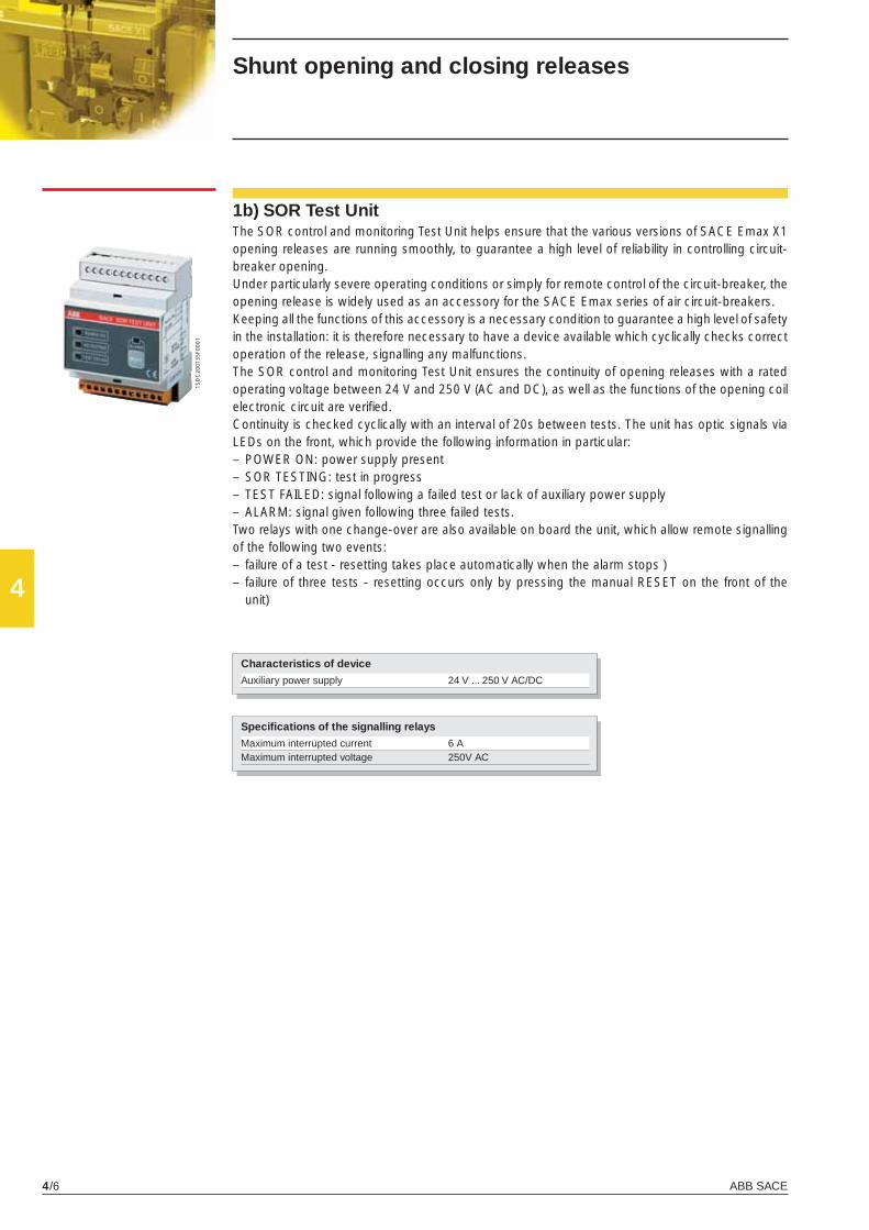
ABB SACE4/6
4
1SD
C20
0135
F000
1
1b) SOR Test UnitThe SOR control and monitoring Test Unit helps ensure that the various versions of SACE Emax X1 opening releases are running smoothly, to guarantee a high level of reliability in controlling circuit-breaker opening.Under particularly severe operating conditions or simply for remote control of the circuit-breaker, the opening release is widely used as an accessory for the SACE Emax series of air circuit-breakers.Keeping all the functions of this accessory is a necessary condition to guarantee a high level of safety in the installation: it is therefore necessary to have a device available which cyclically checks correct operation of the release, signalling any malfunctions.The SOR control and monitoring Test Unit ensures the continuity of opening releases with a rated operating voltage between 24 V and 250 V (AC and DC), as well as the functions of the opening coil electronic circuit are verifi ed.Continuity is checked cyclically with an interval of 20s between tests. The unit has optic signals via LEDs on the front, which provide the following information in particular:– POWER ON: power supply present– SOR TESTING: test in progress– TEST FAILED: signal following a failed test or lack of auxiliary power supply– ALARM: signal given following three failed tests.Two relays with one change-over are also available on board the unit, which allow remote signalling of the following two events:– failure of a test - resetting takes place automatically when the alarm stops )– failure of three tests - resetting occurs only by pressing the manual RESET on the front of the
unit)
Shunt opening and closing releases
Specifi cations of the signalling relays
Maximum interrupted current 6 A Maximum interrupted voltage 250V AC
Characteristics of device
Auxiliary power supply 24 V ... 250 V AC/DC
X1_cap_4_01.indd 6X1_cap_4_01.indd 6 4-04-2007 9:14:114-04-2007 9:14:11
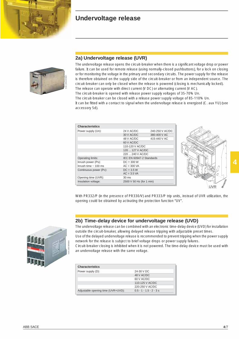
ABB SACE 4/7
4
1SD
C20
0543
F000
1
1SD
C20
0138
F000
1
UVR
Undervoltage release
2a) Undervoltage release (UVR)The undervoltage release opens the circuit-breaker when there is a signifi cant voltage drop or power failure. It can be used for remote release (using normally-closed pushbuttons), for a lock on closing or for monitoring the voltage in the primary and secondary circuits. The power supply for the release is therefore obtained on the supply side of the circuit-breaker or from an independent source. The circuit-breaker can only be closed when the release is powered (closing is mechanically locked).The release can operate with direct current (V DC) or alternating current (V AC).The circuit-breaker is opened with release power supply voltages of 35-70% Un.The circuit-breaker can be closed with a release power supply voltage of 85-110% Un.It can be fi tted with a contact to signal when the undervoltage release is energized (C. aux YU) (see accessory 5d).
2b) Time-delay device for undervoltage release (UVD) The undervoltage release can be combined with an electronic time-delay device (UVD) for installation outside the circuit-breaker, allowing delayed release tripping with adjustable preset times.Use of the delayed undervoltage release is recommended to prevent tripping when the power supply network for the release is subject to brief voltage drops or power supply failures.Circuit-breaker closing is inhibited when it is not powered. The time-delay device must be used with an undervoltage release with the same voltage.
With PR332/P (in the presence of PR330/V) and PR333/P trip units, instead of UVR utilization, the opening could be obtained by activating the protection function “UV”.
Characteristics
Power supply (D): 24-30 V DC 48 V AC/DC 60 V AC/DC 110-125 V AC/DC 220-250 V AC/DCAdjustable opening time (UVR+UVD): 0.5 - 1 - 1.5 - 2 - 3 s
Characteristics
Power supply (Un): 24 V AC/DC 240-250 V AC/DC 30 V AC/DC 380-400 V AC 48 V AC/DC 415-440 V AC 60 V AC/DC 110-120 V AC/DC 120 ... 127 V AC/DC 220 ... 240 V AC/DC Operating limits: IEC EN 60947-2 Standards Inrush power (Ps): DC = 300 WInrush time ~ 100 ms AC = 300 VAContinuous power (Pc): DC = 3.5 W AC = 3.5 VAOpening time (UVR): 30 msInsulation voltage: 2500 V 50 Hz (for 1 min)
X1_cap_4_01.indd 7X1_cap_4_01.indd 7 4-04-2007 9:14:124-04-2007 9:14:12
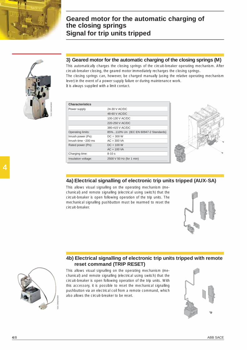
ABB SACE4/8
4
1SD
C20
0544
F000
1
1SD
C20
0605
F000
1
Geared motor for the automatic charging ofthe closing springsSignal for trip units tripped
3) Geared motor for the automatic charging of the closing springs (M)This automatically charges the closing springs of the circuit-breaker operating mechanism. After circuit-breaker closing, the geared motor immediately recharges the closing springs.The closing springs can, however, be charged manually (using the relative operating mechanism lever) in the event of a power supply failure or during maintenance work.It is always supplied with a limit contact.
4a) Electrical signalling of electronic trip units tripped (AUX-SA)
4b) Electrical signalling of electronic trip units tripped with remote reset command (TRIP RESET)
Characteristics
Power supply 24-30 V AC/DC
48-60 V AC/DC
100-130 V AC/DC
220-250 V AC/DC
380-415 V AC/DC
Operating limits: 85%...110% Un (IEC EN 60947-2 Standards)
Inrush power (Ps): DC = 300 W
Inrush time ~200 ms AC = 300 VA
Rated power (Pn): DC = 100 W
AC = 100 VA
Charging time: 8-10 s
Insulation voltage: 2500 V 50 Hz (for 1 min)
This allows visual signalling on the operating mechanism (me-chanical) and remote signalling (electrical using switch) that the circuit-breaker is open following operation of the trip units. The mechanical signalling pushbutton must be rearmed to reset the circuit-breaker.
This allows visual signalling on the operating mechanism (me-chanical) and remote signalling (electrical using switch) that the circuit-breaker is open following operation of the trip units. With this accessory, it is possible to reset the mechanical signalling pushbutton via an electrical coil from a remote command, which also allows the circuit-breaker to be reset.
X1_cap_4_01.indd 8X1_cap_4_01.indd 8 4-04-2007 9:14:154-04-2007 9:14:15
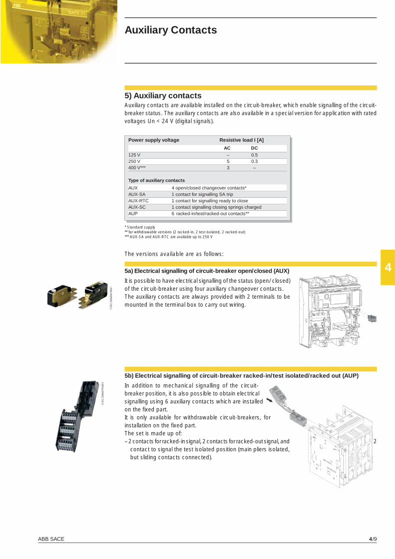
ABB SACE 4/9
4
1SD
C20
0606
F000
1
1SD
C20
0607
F000
1
Auxiliary Contacts
The versions available are as follows:
5) Auxiliary contactsAuxiliary contacts are available installed on the circuit-breaker, which enable signalling of the circuit-breaker status. The auxiliary contacts are also available in a special version for application with rated voltages Un < 24 V (digital signals).
5a) Electrical signalling of circuit-breaker open/closed (AUX)
It is possible to have electrical signalling of the status (open/ closed) of the circuit-breaker using four auxiliary changeover contacts.The auxiliary contacts are always provided with 2 terminals to be mounted in the terminal box to carry out wiring.
5b) Electrical signalling of circuit-breaker racked-in/test isolated/racked out (AUP)
In addition to mechanical signalling of the circuit-breaker position, it is also possible to obtain electrical signalling using 6 auxiliary contacts which are installed on the fi xed part.It is only available for withdrawable circuit-breakers, for installation on the fi xed part.The set is made up of:– 2 contacts for racked-in signal, 2 contacts for racked-out signal, and 2
contact to signal the test isolated position (main pliers isolated, but sliding contacts connected).
* Standard supply ** for withdrawable versions (2 racked-in, 2 test isolated, 2 racked-out)*** AUX-SA and AUX-RTC are available up to 250 V
Power supply voltage Resistive load I [A]
AC DC125 V – 0.5250 V 5 0.3400 V*** 3 – Type of auxiliary contacts
AUX 4 open/closed changeover contacts*AUX-SA 1 contact for signalling SA tripAUX-RTC 1 contact for signalling ready to closeAUX-SC 1 contact signalling closing springs charged AUP 6 racked-in/test/racked-out contacts**
X1_cap_4_01.indd 9X1_cap_4_01.indd 9 4-04-2007 9:14:194-04-2007 9:14:19
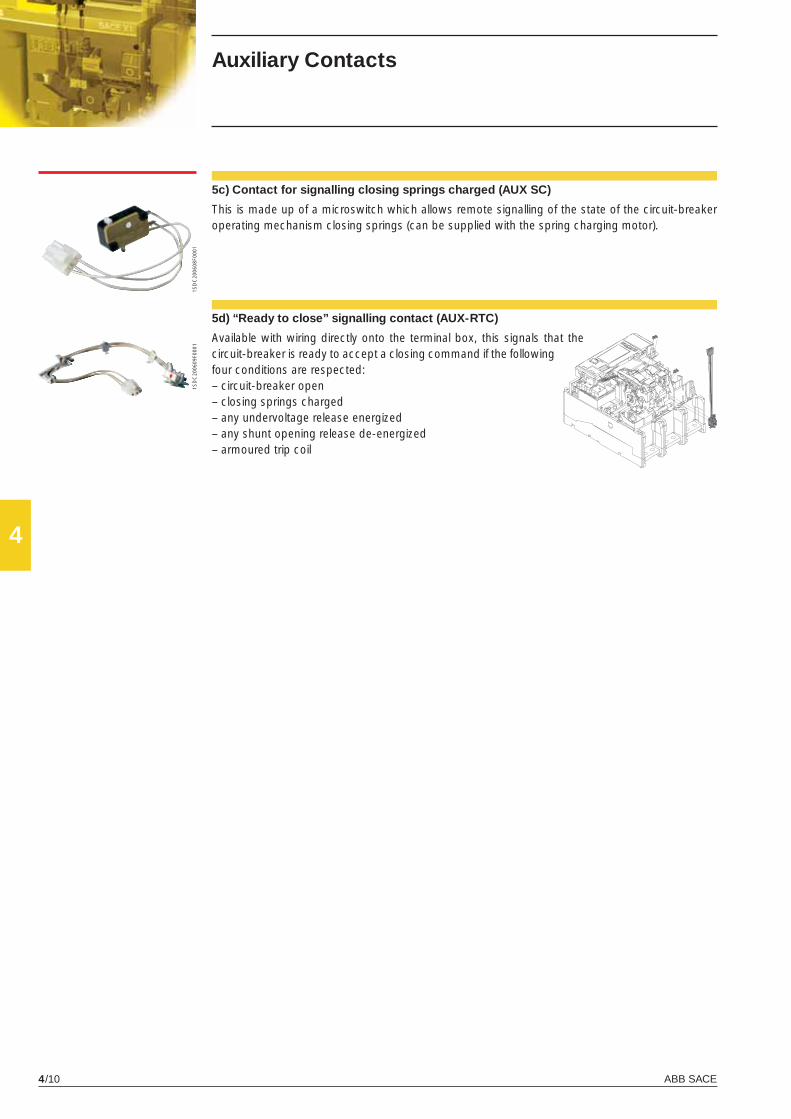
ABB SACE4/10
4
1SD
C20
0608
F000
11S
DC
2006
09F0
001
5c) Contact for signalling closing springs charged (AUX SC)
This is made up of a microswitch which allows remote signalling of the state of the circuit-breaker operating mechanism closing springs (can be supplied with the spring charging motor).
5d) “Ready to close” signalling contact (AUX-RTC)
Available with wiring directly onto the terminal box, this signals that the circuit-breaker is ready to accept a closing command if the following four conditions are respected:– circuit-breaker open– closing springs charged– any undervoltage release energized– any shunt opening release de-energized– armoured trip coil
Auxiliary Contacts
X1_cap_4_01.indd 10X1_cap_4_01.indd 10 4-04-2007 9:14:224-04-2007 9:14:22
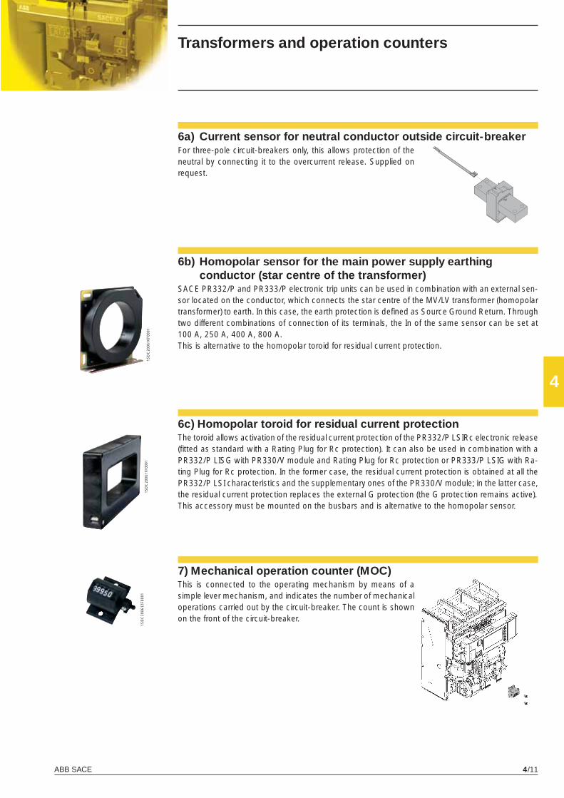
ABB SACE 4/11
4
1SD
C20
0610
F000
11S
DC
2006
11F0
001
1SD
C20
0612
F000
1
Transformers and operation counters
6a) Current sensor for neutral conductor outside circuit-breaker
6b) Homopolar sensor for the main power supply earthing conductor (star centre of the transformer) SACE PR332/P and PR333/P electronic trip units can be used in combination with an external sen-sor located on the conductor, which connects the star centre of the MV/LV transformer (homopolar transformer) to earth. In this case, the earth protection is defi ned as Source Ground Return. Through two different combinations of connection of its terminals, the In of the same sensor can be set at 100 A, 250 A, 400 A, 800 A.This is alternative to the homopolar toroid for residual current protection.
7) Mechanical operation counter (MOC)This is connected to the operating mechanism by means of a simple lever mechanism, and indicates the number of mechanical operations carried out by the circuit-breaker. The count is shown on the front of the circuit-breaker.
For three-pole circuit-breakers only, this allows protection of the neutral by connecting it to the overcurrent release. Supplied on request.
6c) Homopolar toroid for residual current protectionThe toroid allows activation of the residual current protection of the PR332/P LSIRc electronic release (fi tted as standard with a Rating Plug for Rc protection). It can also be used in combination with a PR332/P LISG with PR330/V module and Rating Plug for Rc protection or PR333/P LSIG with Ra-ting Plug for Rc protection. In the former case, the residual current protection is obtained at all the PR332/P LSI characteristics and the supplementary ones of the PR330/V module; in the latter case, the residual current protection replaces the external G protection (the G protection remains active).This accessory must be mounted on the busbars and is alternative to the homopolar sensor.
X1_cap_4_01.indd 11X1_cap_4_01.indd 11 6-04-2007 8:54:506-04-2007 8:54:50
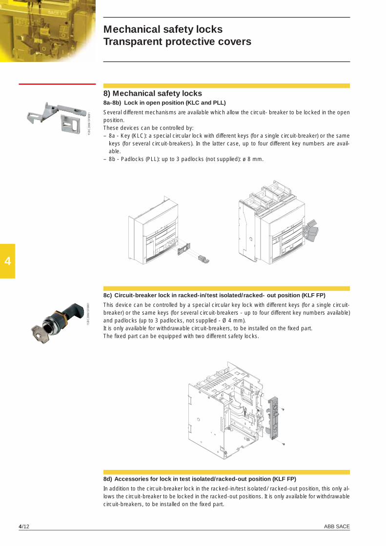
ABB SACE4/12
4
1SD
C20
0613
F000
11S
DC
2006
15F0
001
Mechanical safety locksTransparent protective covers
8) Mechanical safety locks8a-8b) Lock in open position (KLC and PLL)
Several different mechanisms are available which allow the circuit- breaker to be locked in the open position.These devices can be controlled by:– 8a - Key (KLC): a special circular lock with different keys (for a single circuit-breaker) or the same
keys (for several circuit-breakers). In the latter case, up to four different key numbers are avail-able.
– 8b - Padlocks (PLL): up to 3 padlocks (not supplied): ø 8 mm.
8c) Circuit-breaker lock in racked-in/test isolated/racked- out position (KLF FP)
This device can be controlled by a special circular key lock with different keys (for a single circuit-breaker) or the same keys (for several circuit-breakers - up to four different key numbers available) and padlocks (up to 3 padlocks, not supplied - Ø 4 mm).It is only available for withdrawable circuit-breakers, to be installed on the fi xed part.The fi xed part can be equipped with two different safety locks.
8d) Accessories for lock in test isolated/racked-out position (KLF FP)
In addition to the circuit-breaker lock in the racked-in/test isolated/ racked-out position, this only al-lows the circuit-breaker to be locked in the racked-out positions. It is only available for withdrawable circuit-breakers, to be installed on the fi xed part.
X1_cap_4_01.indd 12X1_cap_4_01.indd 12 4-04-2007 9:14:274-04-2007 9:14:27
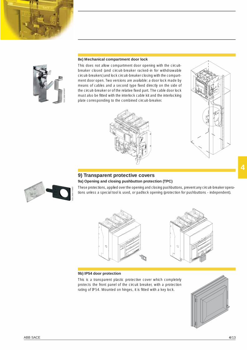
ABB SACE 4/13
4
1SD
C20
0616
F000
1
1SD
C20
0617
F000
1
9b) IP54 door protection
This is a transparent plastic protective cover which completely protects the front panel of the circuit breaker, with a protection rating of IP54. Mounted on hinges, it is fi tted with a key lock.
8e) Mechanical compartment door lock
This does not allow compartment door opening with the circuit-breaker closed (and circuit-breaker racked-in for withdrawable circuit-breakers) and lock circuit-breaker closing with the compart-ment door open. Two versions are available: a door lock made by means of cables and a second type fi xed directly on the side of the circuit-breaker or of the relative fi xed part. The cable door lock must also be fi tted with the interlock cable kit and the interlocking plate corresponding to the combined circuit-breaker.
9) Transparent protective covers9a) Opening and closing pushbutton protection (TPC)
These protections, applied over the opening and closing pushbuttons, prevent any circuit-breaker opera-tions unless a special tool is used, or padlock opening (protection for pushbuttons - independent).
X1_cap_4_01.indd 13X1_cap_4_01.indd 13 4-04-2007 9:14:334-04-2007 9:14:33
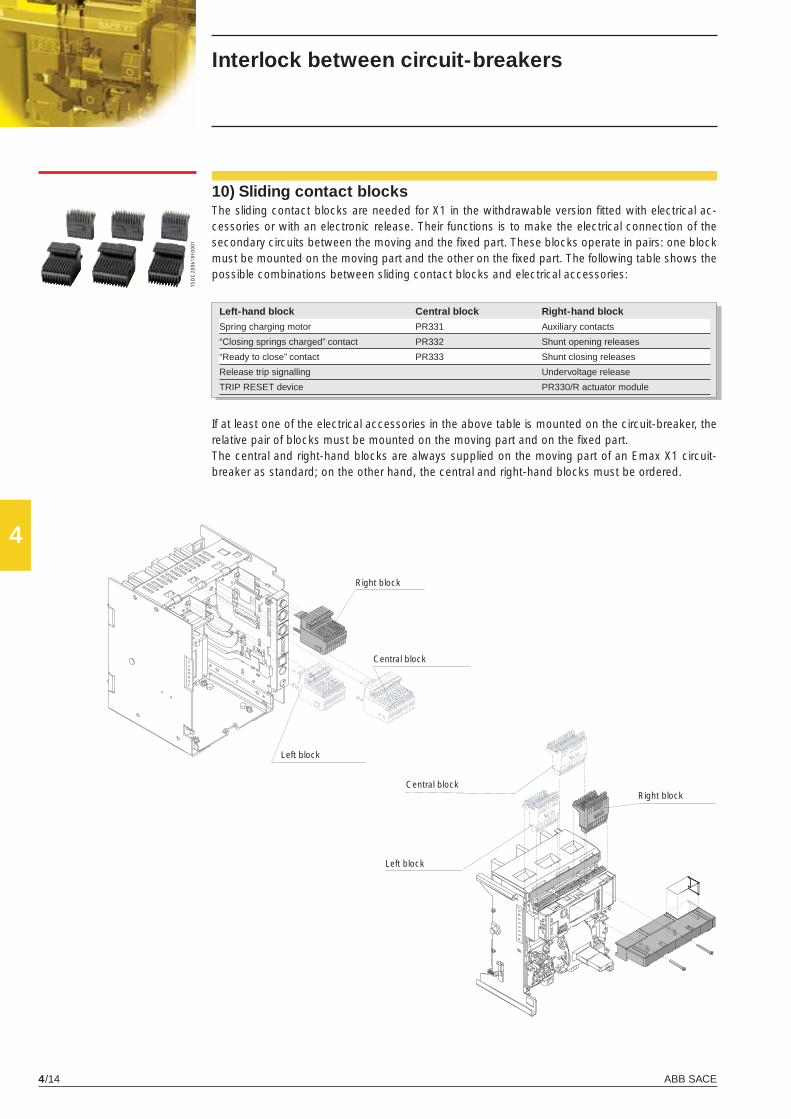
ABB SACE4/14
4
1SD
C20
0618
F000
1
Interlock between circuit-breakers
10) Sliding contact blocksThe sliding contact blocks are needed for X1 in the withdrawable version fi tted with electrical ac-cessories or with an electronic release. Their functions is to make the electrical connection of the secondary circuits between the moving and the fi xed part. These blocks operate in pairs: one block must be mounted on the moving part and the other on the fi xed part. The following table shows the possible combinations between sliding contact blocks and electrical accessories:
Left-hand block Central block Right-hand block
Spring charging motor PR331 Auxiliary contacts
“Closing springs charged” contact PR332 Shunt opening releases
“Ready to close” contact PR333 Shunt closing releases
Release trip signalling Undervoltage release
TRIP RESET device PR330/R actuator module
If at least one of the electrical accessories in the above table is mounted on the circuit-breaker, the relative pair of blocks must be mounted on the moving part and on the fi xed part.The central and right-hand blocks are always supplied on the moving part of an Emax X1 circuit-breaker as standard; on the other hand, the central and right-hand blocks must be ordered.
Right block
Central block
Left block
Right blockCentral block
Left block
X1_cap_4_01.indd 14X1_cap_4_01.indd 14 4-04-2007 9:14:364-04-2007 9:14:36
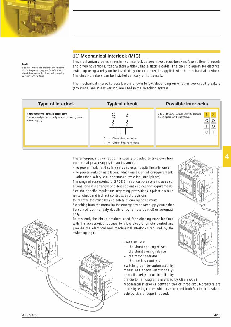
ABB SACE 4/15
4
�
� �
1 2 O O
I O
O I
The mechanical interlocks possible are shown below, depending on whether two circuit-breakers (any model and in any version) are used in the switching system.
Type of interlock Typical circuit Possible interlocks
O = Circuit-breaker open
I = Circuit-breaker closed
Circuit-breaker 1 can only be closed if 2 is open, and viceversa.
Between two circuit-breakersOne normal power supply and one emergency power supply
11) Mechanical interlock (MIC)This mechanism creates a mechanical interlock between two circuit-breakers (even different models and different versions, fi xed/withdrawable) using a fl exible cable. The circuit diagram for electrical switching using a relay (to be installed by the customer) is supplied with the mechanical interlock. The circuit-breakers can be installed vertically or horizontally.
Note:See the “Overall dimensions” and “Electrical circuit diagrams” chapters for information about dimensions (fi xed and withdrawable versions) and settings.
The emergency power supply is usually provided to take over from the normal power supply in two instances:– to power health and safety services (e.g. hospital installations);– to power parts of installations which are essential for requirements
other than safety (e.g. continuous cycle industrial plants).The range of accessories for SACE Emax circuit-breakers includes so-lutions for a wide variety of different plant engineering requirements.See the specifi c regulations regarding protections against overcur-rents, direct and indirect contacts, and provisionsto improve the reliability and safety of emergency circuits.Switching from the normal to the emergency power supply can either be carried out manually (locally or by remote control) or automati-cally.To this end, the circuit-breakers used for switching must be fi tted with the accessories required to allow electric remote control and provide the electrical and mechanical interlocks required by the switching logic.
These include:– the shunt opening release– the shunt closing release– the motor operator– the auxiliary contacts.Switching can be automated by means of a special electronically-controlled relay circuit, installed by the customer (diagrams provided by ABB SACE).Mechanical interlocks between two or three circuit-breakers are made by using cables which can be used both for circuit-breakers side by side or superimposed.
X1_cap_4_01.indd 15X1_cap_4_01.indd 15 4-04-2007 9:14:394-04-2007 9:14:39
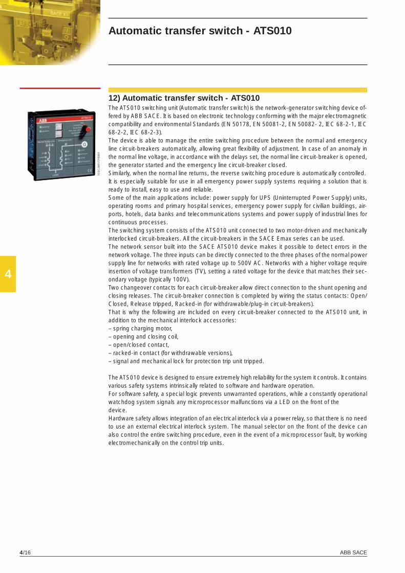
ABB SACE4/16
4
1SD
C20
0177
F000
1
Automatic transfer switch - ATS010
12) Automatic transfer switch - ATS010The ATS010 switching unit (Automatic transfer switch) is the network-generator switching device of-fered by ABB SACE. It is based on electronic technology conforming with the major electromagnetic compatibility and environmental Standards (EN 50178, EN 50081-2, EN 50082- 2, IEC 68-2-1, IEC 68-2-2, IEC 68-2-3).The device is able to manage the entire switching procedure between the normal and emergency line circuit-breakers automatically, allowing great fl exibility of adjustment. In case of an anomaly in the normal line voltage, in accordance with the delays set, the normal line circuit-breaker is opened, the generator started and the emergency line circuit-breaker closed.Similarly, when the normal line returns, the reverse switching procedure is automatically controlled.It is especially suitable for use in all emergency power supply systems requiring a solution that is ready to install, easy to use and reliable.Some of the main applications include: power supply for UPS (Uninterrupted Power Supply) units, operating rooms and primary hospital services, emergency power supply for civilian buildings, air-ports, hotels, data banks and telecommunications systems and power supply of industrial lines for continuous processes.The switching system consists of the ATS010 unit connected to two motor-driven and mechanically interlocked circuit-breakers. All the circuit-breakers in the SACE Emax series can be used.The network sensor built into the SACE ATS010 device makes it possible to detect errors in the network voltage. The three inputs can be directly connected to the three phases of the normal power supply line for networks with rated voltage up to 500V AC. Networks with a higher voltage require insertion of voltage transformers (TV), setting a rated voltage for the device that matches their sec-ondary voltage (typically 100V).Two changeover contacts for each circuit-breaker allow direct connection to the shunt opening and closing releases. The circuit-breaker connection is completed by wiring the status contacts: Open/Closed, Release tripped, Racked-in (for withdrawable/plug-in circuit-breakers).That is why the following are included on every circuit-breaker connected to the ATS010 unit, in addition to the mechanical interlock accessories:– spring charging motor,– opening and closing coil,– open/closed contact,– racked-in contact (for withdrawable versions),– signal and mechanical lock for protection trip unit tripped.
The ATS010 device is designed to ensure extremely high reliability for the system it controls. It contains various safety systems intrinsically related to software and hardware operation.For software safety, a special logic prevents unwarranted operations, while a constantly operational watchdog system signals any microprocessor malfunctions via a LED on the front of thedevice.Hardware safety allows integration of an electrical interlock via a power relay, so that there is no need to use an external electrical interlock system. The manual selector on the front of the device can also control the entire switching procedure, even in the event of a microprocessor fault, by working electromechanically on the control trip units.
X1_cap_4_01.indd 16X1_cap_4_01.indd 16 4-04-2007 9:14:404-04-2007 9:14:40
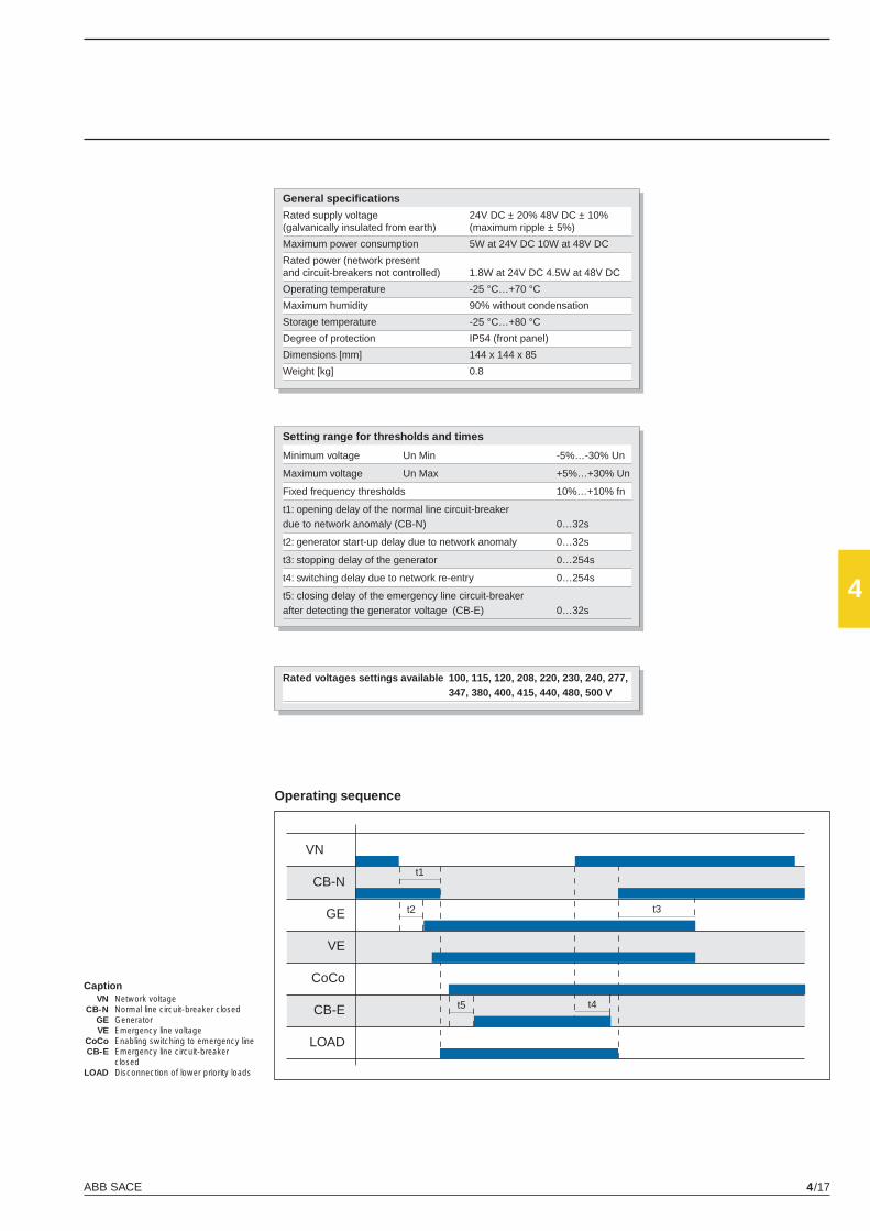
ABB SACE 4/17
4
VN
CB-N
GE
VE
CoCo
CB-E
LOAD
t1
t2
t5 t4
t3
Caption VN Network voltage CB-N Normal line circuit-breaker closed GE Generator VE Emergency line voltage CoCo Enabling switching to emergency line CB-E Emergency line circuit-breaker closed LOAD Disconnection of lower priority loads
Operating sequence
General specifi cations
Rated supply voltage 24V DC ± 20% 48V DC ± 10%(galvanically insulated from earth) (maximum ripple ± 5%)
Maximum power consumption 5W at 24V DC 10W at 48V DC
Rated power (network present and circuit-breakers not controlled) 1.8W at 24V DC 4.5W at 48V DC
Operating temperature -25 °C…+70 °C
Maximum humidity 90% without condensation
Storage temperature -25 °C…+80 °C
Degree of protection IP54 (front panel)
Dimensions [mm] 144 x 144 x 85
Weight [kg] 0.8
Setting range for thresholds and times
Minimum voltage Un Min -5%…-30% Un
Maximum voltage Un Max +5%…+30% Un
Fixed frequency thresholds 10%…+10% fn
t1: opening delay of the normal line circuit-breaker due to network anomaly (CB-N) 0…32s
t2: generator start-up delay due to network anomaly 0…32s
t3: stopping delay of the generator 0…254s
t4: switching delay due to network re-entry 0…254s
t5: closing delay of the emergency line circuit-breaker after detecting the generator voltage (CB-E) 0…32s
Rated voltages settings available 100, 115, 120, 208, 220, 230, 240, 277, 347, 380, 400, 415, 440, 480, 500 V
X1_cap_4_01.indd 17X1_cap_4_01.indd 17 4-04-2007 9:14:414-04-2007 9:14:41
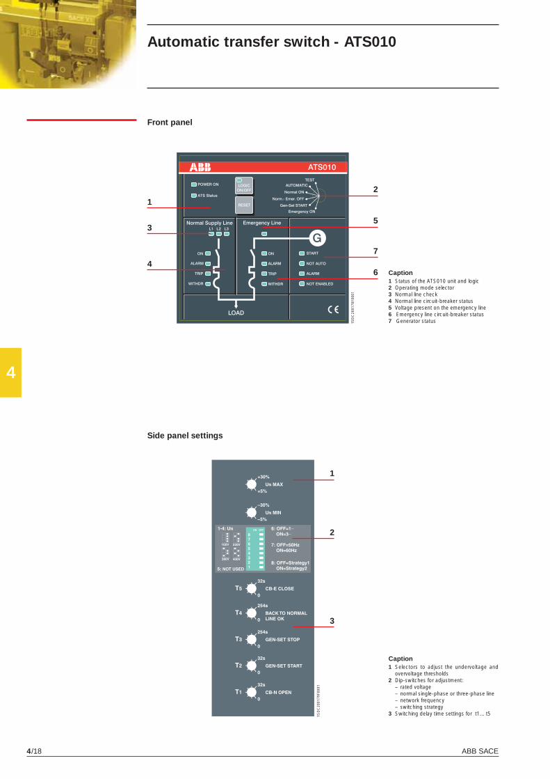
ABB SACE4/18
4
1
3
4
2
5
7
6
1
2
3
1SD
C20
0178
F000
1
1SD
C20
0179
F000
1
Front panel
Caption1 Status of the ATS010 unit and logic2 Operating mode selector3 Normal line check4 Normal line circuit-breaker status5 Voltage present on the emergency line6 Emergency line circuit-breaker status7 Generator status
Caption1 Selectors to adjust the undervoltage and
overvoltage thresholds2 Dip-switches for adjustment: – rated voltage – normal single-phase or three-phase line – network frequency – switching strategy3 Switching delay time settings for t1... t5
Side panel settings
Automatic transfer switch - ATS010
X1_cap_4_01.indd 18X1_cap_4_01.indd 18 4-04-2007 9:14:414-04-2007 9:14:41

ABB SACE 4/19
4
X1_cap_4_01.indd 19X1_cap_4_01.indd 19 4-04-2007 9:14:424-04-2007 9:14:42
X1_cap_5_00.indd 2X1_cap_5_00.indd 2 4-04-2007 9:53:244-04-2007 9:53:24
5
ABB SACE 5/1
Circuit-breaker applications
Contents
Primary and secondary distribution
Selective protection ............................................................................................................. 5/2
Back-up protection ................................................................................................................ 5/5
Directional protection ....................................................................................................... 5/6
Earth fault protection ....................................................................................................... 5/7
Switching and protection of transformers ...................................................................... 5/8
Switching and protection of generators ......................................................................... 5/10
Switching and protection of capacitors .......................................................................... 5/11
X1_cap_5_00.indd 3X1_cap_5_00.indd 3 4-04-2007 9:53:294-04-2007 9:53:29
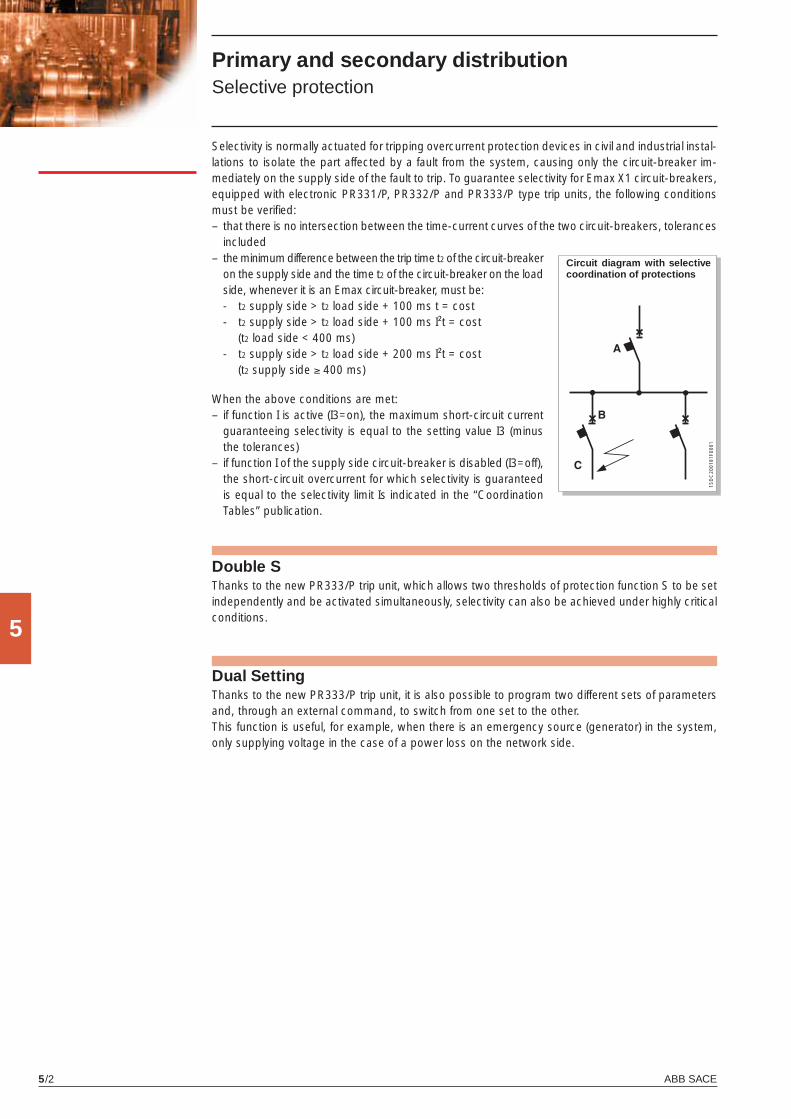
ABB SACE5/2
5
1SD
C20
0181
F000
1
Primary and secondary distribution Selective protection
Selectivity is normally actuated for tripping overcurrent protection devices in civil and industrial instal-lations to isolate the part affected by a fault from the system, causing only the circuit-breaker im-mediately on the supply side of the fault to trip. To guarantee selectivity for Emax X1 circuit-breakers, equipped with electronic PR331/P, PR332/P and PR333/P type trip units, the following conditions must be verifi ed:– that there is no intersection between the time-current curves of the two circuit-breakers, tolerances
included
Circuit diagram with selective coordination of protections
Double SThanks to the new PR333/P trip unit, which allows two thresholds of protection function S to be set independently and be activated simultaneously, selectivity can also be achieved under highly critical conditions.
Dual SettingThanks to the new PR333/P trip unit, it is also possible to program two different sets of parameters and, through an external command, to switch from one set to the other.This function is useful, for example, when there is an emergency source (generator) in the system, only supplying voltage in the case of a power loss on the network side.
– the minimum difference between the trip time t2 of the circuit-breaker on the supply side and the time t2 of the circuit-breaker on the load side, whenever it is an Emax circuit-breaker, must be:
- t2 supply side > t2 load side + 100 ms t = cost - t2 supply side > t2 load side + 100 ms I²t = cost
(t2 load side < 400 ms) - t2 supply side > t2 load side + 200 ms I²t = cost
(t2 supply side ≥ 400 ms)
When the above conditions are met:– if function I is active (I3=on), the maximum short-circuit current
guaranteeing selectivity is equal to the setting value I3 (minus the tolerances)
– if function I of the supply side circuit-breaker is disabled (I3=off), the short-circuit overcurrent for which selectivity is guaranteed is equal to the selectivity limit Is indicated in the “Coordination Tables” publication.
X1_cap_5_01.indd 2X1_cap_5_01.indd 2 4-04-2007 9:53:524-04-2007 9:53:52
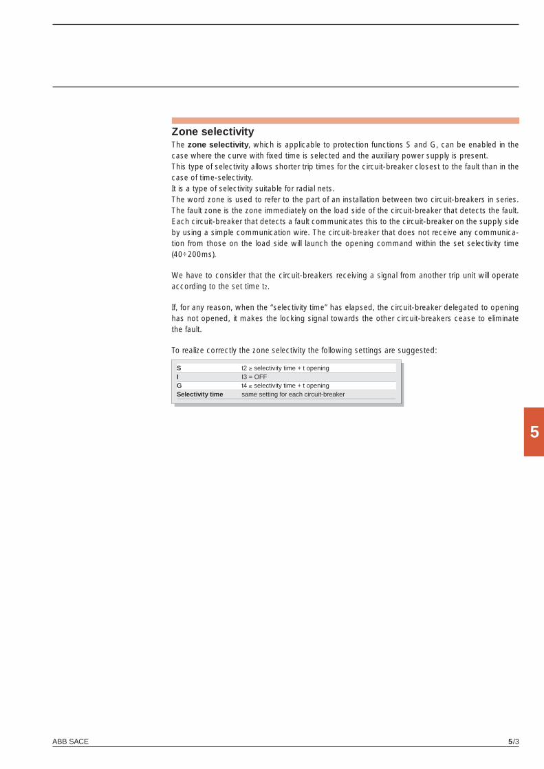
ABB SACE 5/3
5
Zone selectivityThe zone selectivity, which is applicable to protection functions S and G, can be enabled in the case where the curve with fi xed time is selected and the auxiliary power supply is present.This type of selectivity allows shorter trip times for the circuit-breaker closest to the fault than in the case of time-selectivity.It is a type of selectivity suitable for radial nets.The word zone is used to refer to the part of an installation between two circuit-breakers in series. The fault zone is the zone immediately on the load side of the circuit-breaker that detects the fault. Each circuit-breaker that detects a fault communicates this to the circuit-breaker on the supply side by using a simple communication wire. The circuit-breaker that does not receive any communica-tion from those on the load side will launch the opening command within the set selectivity time (40÷200ms).
We have to consider that the circuit-breakers receiving a signal from another trip unit will operate according to the set time t2.
If, for any reason, when the “selectivity time” has elapsed, the circuit-breaker delegated to opening has not opened, it makes the locking signal towards the other circuit-breakers cease to eliminate the fault.
To realize correctly the zone selectivity the following settings are suggested:
S t2 ≥ selectivity time + t opening I I3 = OFFG t4 ≥ selectivity time + t opening Selectivity time same setting for each circuit-breaker
X1_cap_5_01.indd 3X1_cap_5_01.indd 3 4-04-2007 9:53:534-04-2007 9:53:53
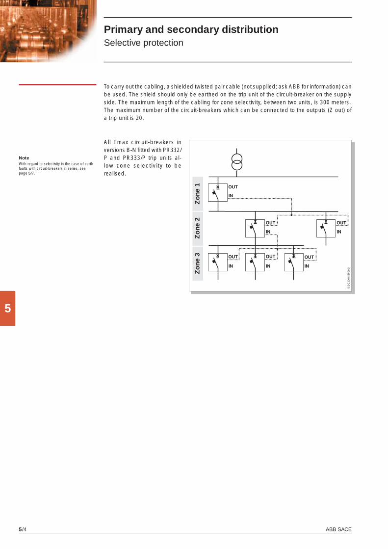
ABB SACE5/4
5
1SD
C20
0186
F000
1
Primary and secondary distribution Selective protection
Zo
ne 3
Zo
ne 2
Zo
ne 1
NoteWith regard to selectivity in the case of earth faults with circuit-breakers in series, see page 5/7.
To carry out the cabling, a shielded twisted pair cable (not supplied; ask ABB for information) can be used. The shield should only be earthed on the trip unit of the circuit-breaker on the supply side. The maximum length of the cabling for zone selectivity, between two units, is 300 meters.The maximum number of the circuit-breakers which can be connected to the outputs (Z out) of a trip unit is 20.
All Emax circuit-breakers in versions B-N fi tted with PR332/P and PR333/P trip units al-low zone selectivity to be realised.
X1_cap_5_01.indd 4X1_cap_5_01.indd 4 4-04-2007 9:53:534-04-2007 9:53:53
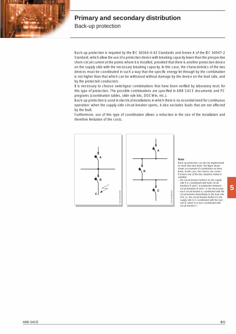
ABB SACE 5/5
5
1SD
C20
0187
F000
1
1SD
C20
0188
F000
1
Primary and secondary distribution Back-up protection
Back-up protection is required by the IEC 60364-4-43 Standards and Annex A of the IEC 60947-2 Standard, which allow the use of a protection device with breaking capacity lower than the prospective short-circuit current at the points where it is installed, provided that there is another protection device on the supply side with the necessary breaking capacity. In this case, the characteristics of the two devices must be coordinated in such a way that the specifi c energy let through by the combination is not higher than that which can be withstood without damage by the device on the load side, and by the protected conductors. It is necessary to choose switchgear combinations that have been verifi ed by laboratory tests for this type of protection. The possible combinations are specifi ed in ABB SACE documents and PC programs (coordination tables, slide rule kits, DOCWin, etc.).Back-up protection is used in electrical installations in which there is no essential need for continuous operation: when the supply-side circuit-breaker opens, it also excludes loads that are not affected by the fault. Furthermore, use of this type of coordination allows a reduction in the size of the installation and therefore limitation of the costs.
NoteBack-up protection can also be implemented on more than two levels: the fi gure above shows an example of coordination on three levels. In this case, the choices are correct if at least one of the two situations below is satisfi ed:– the circuit-breaker furthest on the supply
side A is coordinated with both circuit-breakers B and C (coordination between circuit-breakers B and C is not necessary);
– each circuit-breaker is coordinated with the circuit-breaker immediately to the load side of it, i.e. the circuit-breaker furthest to the supply side A is coordinated with the next one B, which is in turn coordinated with circuit-breaker C.
X1_cap_5_01.indd 5X1_cap_5_01.indd 5 4-04-2007 9:53:534-04-2007 9:53:53
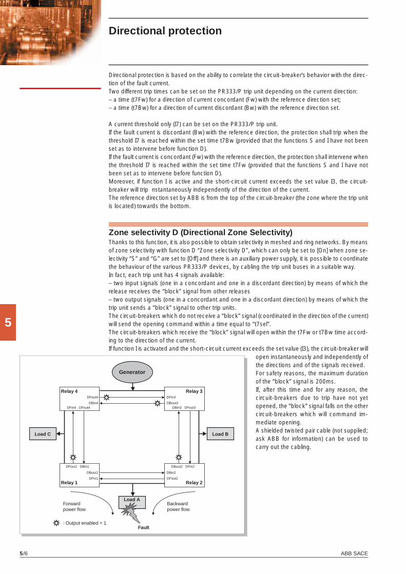
ABB SACE5/6
5
Directional protection
Directional protection is based on the ability to correlate the circuit-breaker’s behavior with the direc-tion of the fault current.Two different trip times can be set on the PR333/P trip unit depending on the current direction:– a time (t7Fw) for a direction of current concordant (Fw) with the reference direction set;– a time (t7Bw) for a direction of current discordant (Bw) with the reference direction set.
A current threshold only (I7) can be set on the PR333/P trip unit.If the fault current is discordant (Bw) with the reference direction, the protection shall trip when the threshold I7 is reached within the set time t7Bw (provided that the functions S and I have not been set as to intervene before function D).If the fault current is concordant (Fw) with the reference direction, the protection shall intervene when the threshold I7 is reached within the set time t7Fw (provided that the functions S and I have not been set as to intervene before function D).Moreover, if function I is active and the short-circuit current exceeds the set value I3, the circuit-breaker will trip nstantaneously independently of the direction of the current.The reference direction set by ABB is from the top of the circuit-breaker (the zone where the trip unit is located) towards the bottom.
Zone selectivity D (Directional Zone Selectivity)Thanks to this function, it is also possible to obtain selectivity in meshed and ring networks. By means of zone selectivity with function D “Zone selectivity D”, which can only be set to [On] when zone se-lectivity “S” and “G” are set to [Off] and there is an auxiliary power supply, it is possible to coordinate the behaviour of the various PR333/P devices, by cabling the trip unit buses in a suitable way.In fact, each trip unit has 4 signals available:– two input signals (one in a concordant and one in a discordant direction) by means of which the release receives the “block” signal from other releases– two output signals (one in a concordant and one in a discordant direction) by means of which the trip unit sends a “block” signal to other trip units.The circuit-breakers which do not receive a “block” signal (coordinated in the direction of the current) will send the opening command within a time equal to “t7sel”.The circuit-breakers which receive the “block” signal will open within the t7Fw or t7Bw time accord-ing to the direction of the current.If function I is activated and the short-circuit current exceeds the set value (I3), the circuit-breaker will
open instantaneously and independently of the directions and of the signals received.For safety reasons, the maximum duration of the “block” signal is 200ms.If, after this time and for any reason, the circuit-breakers due to trip have not yet opened, the “block” signal falls on the other circuit-breakers which will command im-mediate opening. A shielded twisted pair cable (not supplied; ask ABB for information) can be used to carry out the cabling.
Generator
Load C Load B
Load A
Fault: Output enabled = 1
Forwardpower fl ow
Backwardpower fl ow
Relay 1
Relay 4
Relay 2
Relay 3
DFin4 DFout4
DFout1 DBin1
DBin3 DFout3
DBout2 DFin2
DBout1
DFin1
DFout4
DBin4
DBin2
DFout2
DFin3
DBout3
X1_cap_5_01.indd 6X1_cap_5_01.indd 6 6-04-2007 9:00:226-04-2007 9:00:22
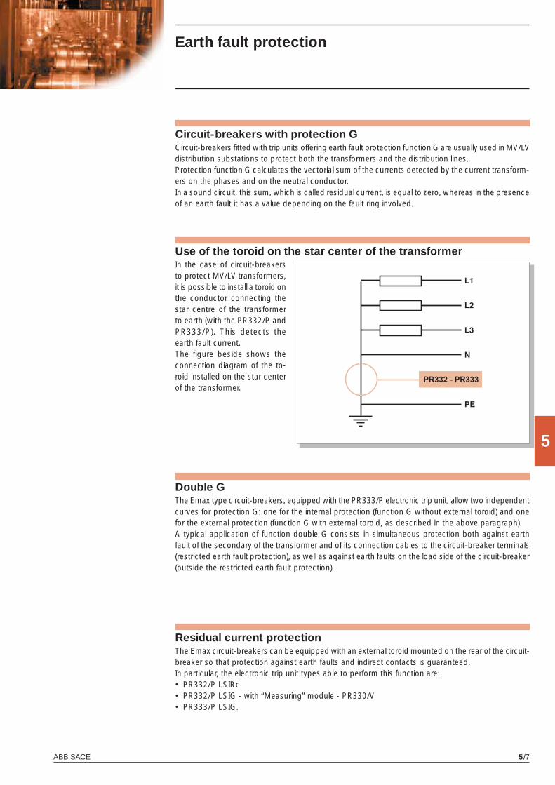
ABB SACE 5/7
5
Earth fault protection
Circuit-breakers fi tted with trip units offering earth fault protection function G are usually used in MV/LV distribution substations to protect both the transformers and the distribution lines.Protection function G calculates the vectorial sum of the currents detected by the current transform-ers on the phases and on the neutral conductor.In a sound circuit, this sum, which is called residual current, is equal to zero, whereas in the presence of an earth fault it has a value depending on the fault ring involved.
Circuit-breakers with protection G
Use of the toroid on the star center of the transformer
Residual current protectionThe Emax circuit-breakers can be equipped with an external toroid mounted on the rear of the circuit-breaker so that protection against earth faults and indirect contacts is guaranteed.In particular, the electronic trip unit types able to perform this function are:• PR332/P LSIRc• PR332/P LSIG - with “Measuring” module - PR330/V• PR333/P LSIG.
In the case of circuit-breakers to protect MV/LV transformers, it is possible to install a toroid on the conductor connecting the star centre of the transformer to earth (with the PR332/P and PR333/P). This detects the earth fault current.The figure beside shows the connection diagram of the to-roid installed on the star center of the transformer.
Double GThe Emax type circuit-breakers, equipped with the PR333/P electronic trip unit, allow two independent curves for protection G: one for the internal protection (function G without external toroid) and one for the external protection (function G with external toroid, as described in the above paragraph).A typical application of function double G consists in simultaneous protection both against earth fault of the secondary of the transformer and of its connection cables to the circuit-breaker terminals (restricted earth fault protection), as well as against earth faults on the load side of the circuit-breaker (outside the restricted earth fault protection).
X1_cap_5_01.indd 7X1_cap_5_01.indd 7 4-04-2007 9:53:544-04-2007 9:53:54
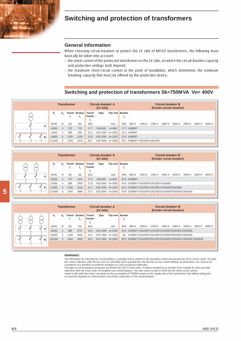
ABB SACE5/8
5
Switching and protection of transformers
Switching and protection of transformers Sk=750MVA Vn= 400V
WARNING!The information for selecting the circuit-breakers is provided only in relation to the operating current and prospective short-circuit current. To make the correct selection, other factors such as selectivity, back-up protection, the decision to use current-limiting circuit-breakers, etc. have to be considered. It is therefore essential for designers to carry out precise verifi cation.The types of circuit-breakers proposed are all from the SACE Emax series. Positions marked by an asterisk (*) are suitable for other possibleselections from the Tmax series of moulded-case circuit-breakers. One also needs to bear in mind that the short-circuit currentsshown in the table have been calculated on the assumption of 750MVA power on the supply side of the transformers and without taking intoaccount the impedances of the busbars and of the connections to the circuit-breakers.
Transformer Circuit-breaker A Circuit-breaker B (LV side) (Feeder circuit-breaker)
Sr Uk Transf Busbar Transf Type Trip unit Busbar Ir Ib Feeder Ik
Ik
[kVA] % [A] [A] [kA] size [kA] 800 A 1000 A 1250 A 1600 A 2000 A 2500 A 3200 A 4000 A
1x500 4 722 722 17.7 X1B 800 In=800 17.7 X1B800*
1x630 4 909 909 22.3 X1B 1000 In=1000 22.3 X1B800*
1x800 5 1155 1155 22.6 X1B 1250 In=1250 22.6 X1B800*
1x1000 5 1443 1443 28.1 X1B 1600 In=1600 28.1 X1B800* X1B1000* X1B1250*
Transformer Circuit-breaker A Circuit-breaker B (LV side) (Feeder circuit-breaker)
Sr Uk Transf Busbar Transf Type Trip unit Busbar Ir Ib Feeder Ik
Ik
[kVA] % [A] [A] [kA] size [kA] 800 A 1000 A 1250 A 1600 A 2000 A 2500 A 3200 A 4000 A
2x500 4 722 1444 17.5 X1B 800 In=800 35.9 X1B800*
2x630 4 909 1818 21.8 X1B 1000 In=1000 43.6 X1N800* X1N1000* X1N1250* X1N1600*
2x800 5 1155 2310 22.1 X1B 1250 In=1250 44.3 X1N800* X1N1000* X1N1250* X1N1600* E2N2000
2x1000 5 1443 2886 27.4 X1B 1600 In=1600 54.8 X1N800* X1N1000* X1N1250* X1N1600* E2N2000 E3N2500
Transformer Circuit-breaker A Circuit-breaker B (LV side) (Feeder circuit-breaker)
Sr Uk Transf Busbar Transf Type Trip unit Busbar Ir Ib Feeder Ik
Ik
[kVA] % [A] [A] [kA] size [kA] 800 A 1000 A 1250 A 1600 A 2000 A 2500 A 3200 A 4000 A
3x630 4 909 2727 42.8 X1N 1000 In=1000 64.2 X1N800* X1N1000* X1N1250* X1N1600* E2N2000 E3N2500
3x800 5 1155 3465 43.4 X1N 1250 In=1250 65 X1N800* X1N1000* X1N1250* X1N1600* E2N2000 E3N2500
3x1000 5 1443 4329 53.5 X1N 1600 In=1600 80.2 E2S800* E2S1000* E2S1250* E2S1600* E2S2000 E3H2500 E3H3200
General information When choosing circuit-breakers to protect the LV side of MV/LV transformers, the following must basically be taken into account:– the rated current of the protected transformer on the LV side, on which the circuit-breaker capacity
and protection settings both depend;– the maximum short-circuit current at the point of installation, which determines the minimum
breaking capacity that must be offered by the protection device.
X1_cap_5_01.indd 8X1_cap_5_01.indd 8 4-04-2007 9:53:544-04-2007 9:53:54
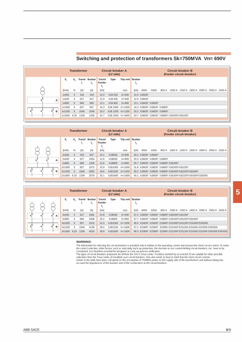
ABB SACE 5/9
5
Switching and protection of transformers Sk=750MVA Vn= 690V
WARNING!The information for selecting the circuit-breakers is provided only in relation to the operating current and prospective short-circuit current. To make the correct selection, other factors such as selectivity, back-up protection, the decision to use current-limiting circuit-breakers, etc. have to be considered. It is therefore essential for designers to carry out precise verifi cation.The types of circuit-breakers proposed are all from the SACE Emax series. Positions marked by an asterisk (*) are suitable for other possibleselections from the Tmax series of moulded-case circuit-breakers. One also needs to bear in mind that the short-circuit currentsshown in the table have been calculated on the assumption of 750MVA power on the supply side of the transformers and without taking intoaccount the impedances of the busbars and of the connections to the circuit-breakers.
Transformer Circuit-breaker A Circuit-breaker B (LV side) (Feeder circuit-breaker)
Sr Uk Transf Busbar Transf Type Trip unit Busbar Ir Ib Feeder Ik
Ik
[kVA] % [A] [A] [kA] size [kA] 400A 630A 800 A 1000 A 1250 A 1600 A 2000 A 2500 A 3200 A
1x500 4 418 418 10.3 X1B 630 In=630 10.3 X1B630*
1x630 4 527 527 12.9 X1B 630 In=630 12.9 X1B630*
1x800 5 669 669 13.1 X1B 800 In=800 13.1 X1B630* X1B630*
1x1000 5 837 837 16.3 X1B 1000 In=1000 16.3 X1B630* X1B630* X1B800*
1x1250 5 1046 1046 20.2 X1B 1250 In=1250 20.2 X1B630* X1B630* X1B800*
1x1600 6.25 1339 1339 20.7 X1B 1600 In=1600 20.7 X1B630* X1B630* X1B800* X1B1000* X1B1250*
Transformer Circuit-breaker A Circuit-breaker B (LV side) (Feeder circuit-breaker)
Sr Uk Transf Busbar Transf Type Trip unit Busbar Ir Ib Feeder Ik
Ik
[kVA] % [A] [A] [kA] size [kA] 400A 630A 800 A 1000 A 1250 A 1600 A 2000 A 2500 A 3200 A
2x500 4 418 837 10.1 X1B630 In=630 20.2 X1B630* X1B630*
2x630 4 527 1054 12.6 X1B630 In=800 25.3 X1B630* X1B630* X1B800*
2x800 5 689 1339 12.6 X1B800 In=800 25.7 X1B630* X1B630* X1B800* X1B1000*
2x1000 5 837 1673 15.9 X1B1000 In=1000 31.8 X1B630* X1B630* X1B800* X1B1000* X1B1250*
2x1250 5 1046 2092 19.6 X1B1250 In=1250 39.2 X1B630* X1B630* X1B800* X1B1000* X1B1250* X1B1600*
2x1600 6.25 1339 2678 20.1 X1B1600 In=1600 40.1 X1B630* X1B630* X1B800* X1B1000* X1B1250* X1B1600* E2B2000
Transformer Circuit-breaker A Circuit-breaker B (LV side) (Feeder circuit-breaker)
Sr Uk Transf Busbar Transf Type Trip unit Busbar Ir Ib Feeder Ik
Ik
[kVA] % [A] [A] [kA] size [kA] 400A 630A 800 A 1000 A 1250 A 1600 A 2000 A 2500 A 3200 A
3x630 4 527 1581 24.8 X1B630 In=630 37.2 X1B630* X1B630* X1B800* X1B1000* X1B1250*
3x800 5 669 2008 25.2 X1B800 In=800 37.7 X1B630* X1B630* X1B800* X1B1000* X1B1250* X1B1600*
3x1000 5 837 2510 31.0 X1B1000 In=1000 46.5 X1N630* X1N630* X1N800* X1N1000* X1N1250* X1N1600* E2N2000
3x1250 5 1046 3138 38.0 X1B1250 In=1600 57.1 E2S800* E2S800* E2S800 E2S1000* E2S1200 E2S1600 E2S2000 E3N2500
3x1600 6.25 1339 4016 38.9 X1B1600 In=1600 58.3 E2S800* E2S800* E2S800 E2S1000* E2S1200 E2S1600 E2S2000 E3N2500 E3N3200
X1_cap_5_01.indd 9X1_cap_5_01.indd 9 4-04-2007 9:53:554-04-2007 9:53:55
ABB SACE5/10
5
Switching and protection of generators
Emax circuit-breakers are suitable for use with low-voltage generators employed in the following applications:A - back-up generators for primary loads B - generators disconnected from the supply networkC - generators for small power stations connected in parallel with other generators and, possibly,
with the power supply network.
In cases A and B, the generator does not operate in parallel with the power supply network: the short-circuit current therefore depends on the generator itself and, possibly, on the connected loads.In case C, the breaking capacity must be determined by assessing the short-circuit current imposed by the network at the point of circuit-breaker installation. The main points to check for generator protection are: – the short-circuit current delivered by the generator; this can only be assessed if one is familiar with
the machine’s typical reactance and time constants. Here one can simply note that low short-circuit protection device settings are normally required (2-4 times In);
– the thermal overload limit of the machine. According to the IEC 60034-1 Standard, this value is set at 1.5xIn for a period of 30 seconds for generators up to 1200 MVAr.
Reverse power protection RP The reverse power protection is tripped when active power is incoming to the generator rather than outgoing as it is under normal conditions. Power reversal takes place if the mechanical power sup-plied by the main motor driving the generator drops sharply. In this condition, the generator acts as a motor, and can cause serious damage to the prime movers, such as overheating in steam turbines, cavitation in hydraulic turbines, or explosions of uncombusted diesel fuel in diesel engines.
X1_cap_5_01.indd 10X1_cap_5_01.indd 10 4-04-2007 9:53:564-04-2007 9:53:56
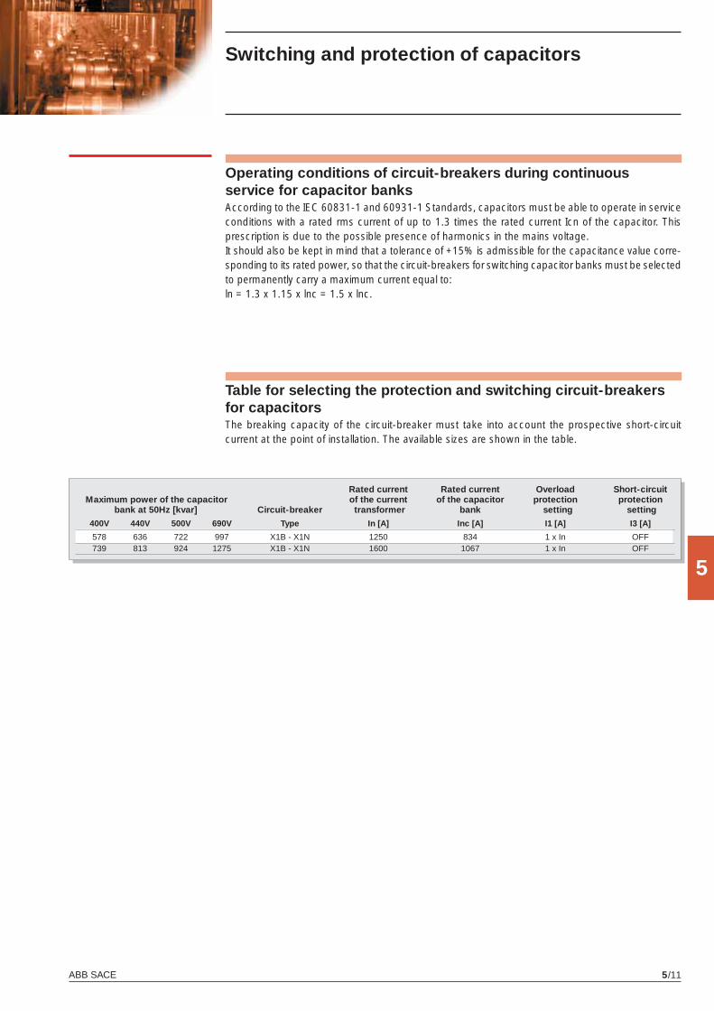
ABB SACE 5/11
5
Switching and protection of capacitors
Operating conditions of circuit-breakers during continuous service for capacitor banksAccording to the IEC 60831-1 and 60931-1 Standards, capacitors must be able to operate in service conditions with a rated rms current of up to 1.3 times the rated current Icn of the capacitor. This prescription is due to the possible presence of harmonics in the mains voltage.It should also be kept in mind that a tolerance of +15% is admissible for the capacitance value corre-sponding to its rated power, so that the circuit-breakers for switching capacitor banks must be selected to permanently carry a maximum current equal to:ln = 1.3 x 1.15 x lnc = 1.5 x lnc.
Table for selecting the protection and switching circuit-breakers for capacitors The breaking capacity of the circuit-breaker must take into account the prospective short-circuit current at the point of installation. The available sizes are shown in the table.
Rated current Rated current Overload Short-circuit Maximum power of the capacitor of the current of the capacitor protection protection bank at 50Hz [kvar] Circuit-breaker transformer bank setting setting
400V 440V 500V 690V Type In [A] Inc [A] I1 [A] I3 [A]
578 636 722 997 X1B - X1N 1250 834 1 x In OFF 739 813 924 1275 X1B - X1N 1600 1067 1 x In OFF
X1_cap_5_01.indd 11X1_cap_5_01.indd 11 4-04-2007 9:53:564-04-2007 9:53:56
X1_cap_6_00.indd 2X1_cap_6_00.indd 2 4-04-2007 9:54:364-04-2007 9:54:36
6
ABB SACE 6/1
Overall dimensions
Contents
Fixed circuit-breaker ........................................................................................................ 6/2
Withdrawable circuit-breaker ........................................................................................... 6/7
Mechanical interlock ........................................................................................................ 6/8
Distances to be respected ............................................................................................... 6/8
X1_cap_6_00.indd 3X1_cap_6_00.indd 3 4-04-2007 9:54:414-04-2007 9:54:41
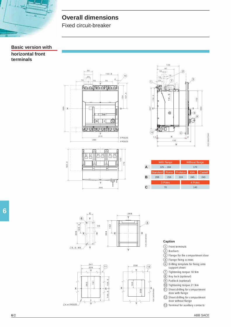
ABB SACE6/2
61S
DC
2005
47F0
001
1SD
C20
0548
F000
1
1SD
C20
0549
F000
1
Caption
1 Front terminals
2 Busbars
3 Flange for the compartment door
4 Flange fi xing screws
6 Drilling template for fi xing onto support sheet
7 Tightening torque 18 Nm
8 Key lock (optional)
9 Padlock (optional)
10 Tightening torque 21 Nm
11 Sheet drilling for compartment door with fl ange
12 Sheet drilling for compartment door without fl ange
13 Terminal for auxiliary contacts
Overall dimensions Fixed circuit-breaker
Basic version withhorizontal front terminals
4 POLES
3 POLES
With fl ange Without fl ange
A 125 ... 164 170
Standard Ronis Profalux Kirk Castell
B 208 216 224 245 243
HOLES
3 Poles 4 Poles
C 70 140
X1_cap_6_01.indd 2X1_cap_6_01.indd 2 3-04-2007 17:11:393-04-2007 17:11:39
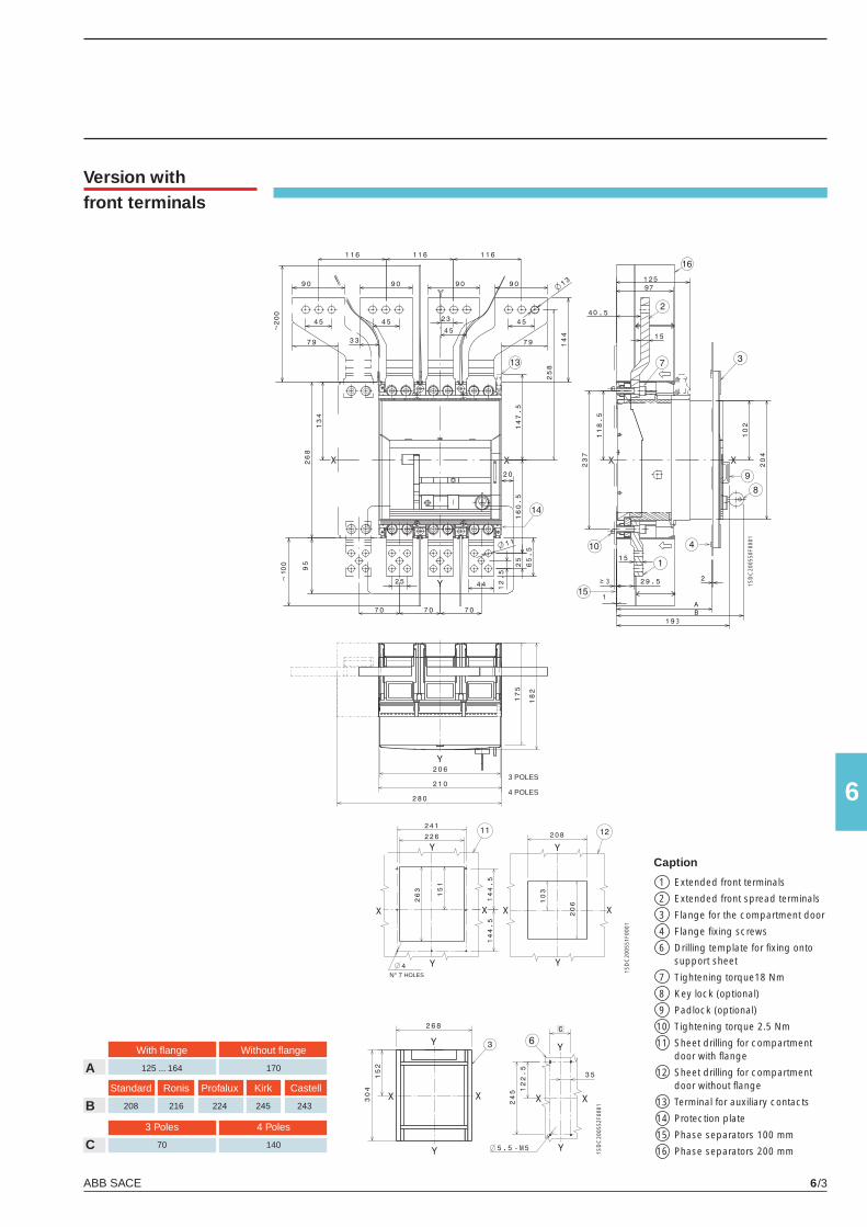
ABB SACE 6/3
6
N° 7
1SD
C20
0550
F000
1
1SD
C20
0551
F000
1
1SD
C20
0552
F000
1
Version withfront terminals
With fl ange Without fl ange
A 125 ... 164 170
Standard Ronis Profalux Kirk Castell
B 208 216 224 245 243
3 Poles 4 Poles
C 70 140
Caption
1 Extended front terminals
2 Extended front spread terminals
3 Flange for the compartment door
4 Flange fi xing screws
6 Drilling template for fi xing onto support sheet
7 Tightening torque18 Nm
8 Key lock (optional)
9 Padlock (optional)
10 Tightening torque 2.5 Nm
11 Sheet drilling for compartment door with fl ange
12 Sheet drilling for compartment door without fl ange
13 Terminal for auxiliary contacts
14 Protection plate
15 Phase separators 100 mm
16 Phase separators 200 mm
4 POLES
3 POLES
HOLES
X1_cap_6_01.indd 3X1_cap_6_01.indd 3 3-04-2007 17:11:403-04-2007 17:11:40
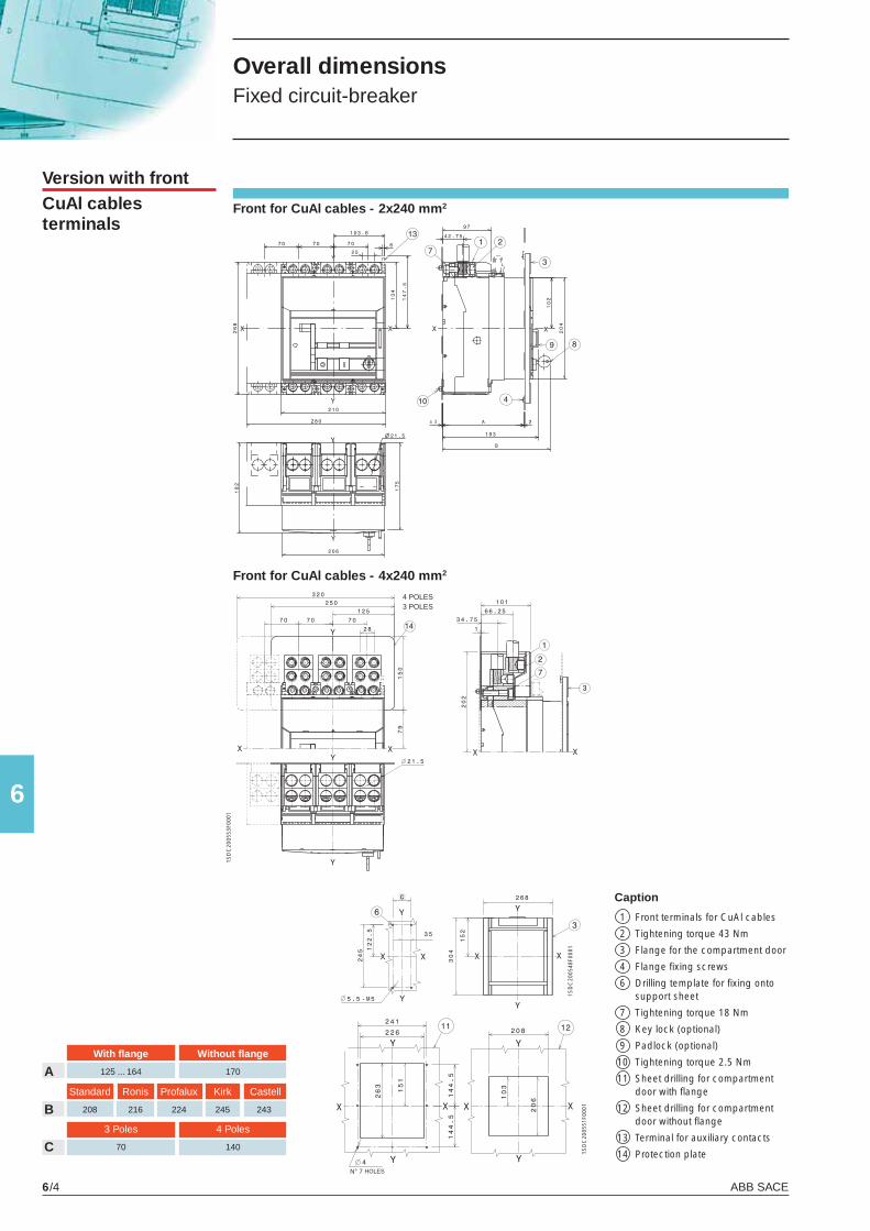
ABB SACE6/4
6
N° 7
1SD
C20
0553
F000
1
1SD
C20
0551
F000
1
1SD
C20
0548
F000
1
Version with frontCuAl cables terminals
Overall dimensions Fixed circuit-breaker
Caption
1 Front terminals for CuAl cables
2 Tightening torque 43 Nm
3 Flange for the compartment door
4 Flange fi xing screws
6 Drilling template for fi xing onto support sheet
7 Tightening torque 18 Nm
8 Key lock (optional)
9 Padlock (optional)
10 Tightening torque 2.5 Nm
11 Sheet drilling for compartment door with fl ange
12 Sheet drilling for compartment door without fl ange
13 Terminal for auxiliary contacts
14 Protection plate
With fl ange Without fl ange
A 125 ... 164 170
Standard Ronis Profalux Kirk Castell
B 208 216 224 245 243
3 Poles 4 Poles
C 70 140
4 POLES3 POLES
HOLES
Front for CuAl cables - 2x240 mm2
Front for CuAl cables - 4x240 mm2
X1_cap_6_01.indd 4X1_cap_6_01.indd 4 3-04-2007 17:11:413-04-2007 17:11:41
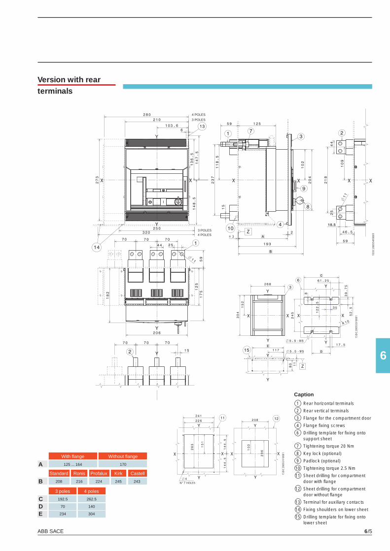
ABB SACE 6/5
6
18.5
N° 7
1SD
C20
0554
F000
1
1SD
C20
0555
F000
1
1SD
C20
0551
F000
1
Version with rearterminals
4 POLES
3 POLES
3 poles 4 poles
C 192.5 262.5
D 70 140
E 234 304
Caption
1 Rear horizontal terminals
2 Rear vertical terminals
3 Flange for the compartment door
4 Flange fi xing screws
6 Drilling template for fi xing onto support sheet
7 Tightening torque 20 Nm
8 Key lock (optional)
9 Padlock (optional)
10 Tightening torque 2.5 Nm
11 Sheet drilling for compartment door with fl ange
12 Sheet drilling for compartment door without fl ange
13 Terminal for auxiliary contacts
14 Fixing shoulders on lower sheet
15 Drilling template for fi xing onto lower sheet
With fl ange Without fl ange
A 125 ... 164 170
Standard Ronis Profalux Kirk Castell
B 208 216 224 245 243 HOLES
4 POLES3 POLES
X1_cap_6_01.indd 5X1_cap_6_01.indd 5 3-04-2007 17:11:413-04-2007 17:11:41
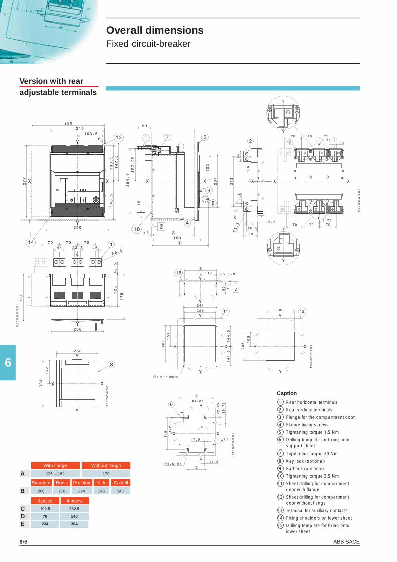
ABB SACE6/6
6
Standard Ronis Profalux Kirk Castell
B 208 216 224 245 243
1SD
C20
0556
F000
1
1SD
C20
0557
F000
1
1SD
C20
0558
F000
1
1SD
C20
0559
F000
1
1SD
C20
0560
F000
1
Overall dimensions Fixed circuit-breaker
Version with rearadjustable terminals
3 poles 4 poles
C 192.5 262.5
D 70 140
E 234 304
With fl ange Without fl ange
A 125 ... 164 170
HOLES
Caption
1 Rear horizontal terminals
2 Rear vertical terminals
3 Flange for the compartment door
4 Flange fi xing screws
5 Tightening torque 1.5 Nm
6 Drilling template for fi xing onto support sheet
7 Tightening torque 20 Nm
8 Key lock (optional)
9 Padlock (optional)
10 Tightening torque 2.5 Nm
11 Sheet drilling for compartment door with fl ange
12 Sheet drilling for compartment door without fl ange
13 Terminal for auxiliary contacts
14 Fixing shoulders on lower sheet
15 Drilling template for fi xing onto lower sheet
X1_cap_6_01.indd 6X1_cap_6_01.indd 6 3-04-2007 17:11:423-04-2007 17:11:42
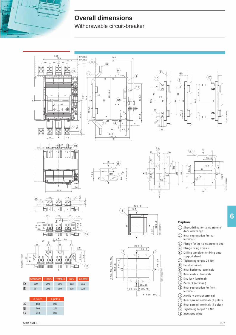
ABB SACE 6/7
6
A 160 230
B 206 276
C 219 289
Standard Ronis Profalux Kirk Castell
D 290 298 306 313 311
E 287 291 299 298 228
1SD
C20
0561
F000
1
1SD
C20
0562
F000
11S
DC
2005
63F0
001
1SD
C20
0564
F000
1
1SD
C20
0565
F000
11S
DC
2005
66F0
001
Overall dimensions Withdrawable circuit-breaker
4 POLES3 POLES
3 poles 4 poles
Caption
1 Sheet drilling for compartment door with fl ange
2 Rear segregation for rear terminals
3 Flange for the compartment door
4 Flange fi xing screws
6 Drilling template for fi xing onto support sheet
7 Tightening torque 21 Nm
8 Front terminals
9 Rear horizontal terminals
10 Rear vertical terminals
11 Key lock (optional)
12 Padlock (optional)
13 Rear segregation for front terminals
14 Auxiliary contact terminal
15 Rear spread terminals (3 poles)
16 Rear spread terminals (4 poles)
17 Tightening torque 18 Nm
18 Insulating plate
X1_cap_6_01.indd 7X1_cap_6_01.indd 7 3-04-2007 17:11:423-04-2007 17:11:42
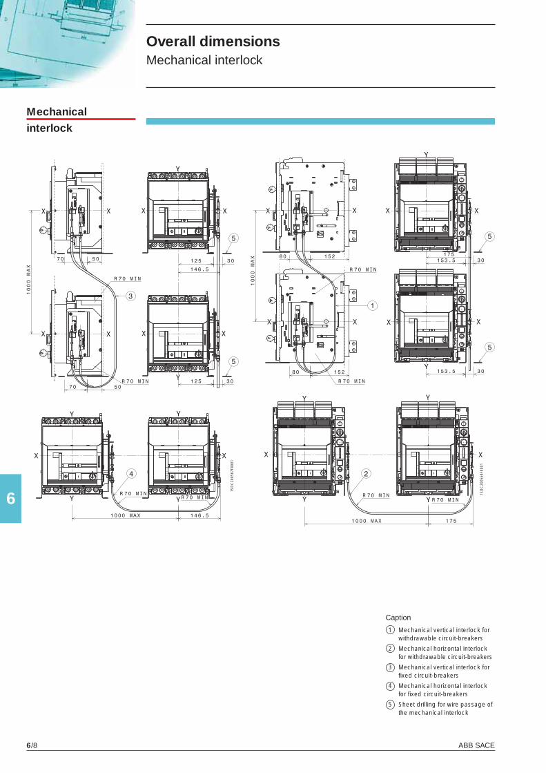
ABB SACE6/8
6
1SD
C20
0567
F000
1
1SD
C20
0568
F000
1
Mechanicalinterlock
Overall dimensions Mechanical interlock
Caption
1 Mechanical vertical interlock for withdrawable circuit-breakers
2 Mechanical horizontal interlock for withdrawable circuit-breakers
3 Mechanical vertical interlock for fi xed circuit-breakers
4 Mechanical horizontal interlock for fi xed circuit-breakers
5 Sheet drilling for wire passage of the mechanical interlock
X1_cap_6_01.indd 8X1_cap_6_01.indd 8 3-04-2007 17:11:433-04-2007 17:11:43
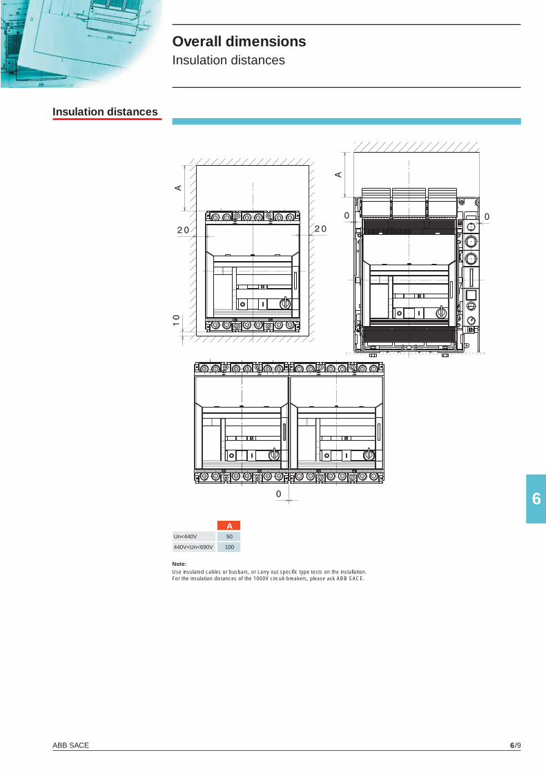
ABB SACE 6/9
6
Un<440V 50
440V<Un<690V 100
A
Overall dimensionsInsulation distances
Note: Use insulated cables or busbars, or carry out specifi c type tests on the installation. For the insulation distances of the 1000V circuit-breakers, please ask ABB SACE.
Insulation distances
X1_cap_6_01.indd 9X1_cap_6_01.indd 9 3-04-2007 17:11:443-04-2007 17:11:44
X1_cap_7_00.indd 2X1_cap_7_00.indd 2 3-04-2007 17:13:303-04-2007 17:13:30
7
ABB SACE 7/1
Circuit diagrams
Contents
Reading information - Circuit-breakers .......................................................................... 7/2
Reading information - ATS010 ........................................................................................ 7/5
Circuit diagram symbols (IEC 60617 and CEI 3-14 ... 3-26 Standards) ........................ 7/5
Circuit diagrams
Circuit-breakers .................................................................................................................. 7/7
Electrical accessories ......................................................................................................... 7/8
Automatic transfer-switch ATS010 ...................................................................................... 7/12
X1_cap_7_00.indd 3X1_cap_7_00.indd 3 3-04-2007 17:13:353-04-2007 17:13:35
ABB SACE7/2
7
Circuit diagrams Reading information - Circuit-breakers
WarningBefore installing the circuit-breaker, carefully read notes F and O on the circuit diagrams.
Operating status shownThe circuit diagram is for the following conditions:- withdrawable circuit-breaker, open and racked-in- circuits de-energised- trip units not tripped- motor operating mechanism with springs discharged.
Versions Though the diagram shows a circuit-breaker in withdrawable version, it can be applied to a fi xed version circuit-breaker as well.
Fixed versionThe control circuits are fi tted between terminals XV (connector X12-X13-X14-X15 are not supplied).With this version, the applications indicated in fi gure 31A cannot be provided.
Withdrawable versionThe control circuits are fi tted between the poles of connector X12-X13-X14-X15 (terminal box XV is not supplied).
Version without overcurrent trip unitWith this version, the applications indicated in fi gures 13A, 14A, 41A, 42A, 43A, 44A, 45A and 62A cannot be provided.
Version with PR331/P electronic trip unitWith this version, the applications indicated in fi gures 42A, 43A, 44A, 45A cannot be provided.
Version with PR332/P electronic trip unitWith this version, the applications indicated in fi gure 41A cannot be provided.
Version with PR333/P electronic trip unitWith this version, the applications indicated in fi gure 41A cannot be provided.
Caption = Circuit diagram fi gure number* = See note indicated by letterA1 = Circuit-breaker accessoriesA3 = Accessories applied to the fi xed part of the circuit-breaker (for withdrawable version only)A4 = Example switchgear and connections for control and signalling, outside the circuit-breakerA19 = PR330/R actuation unitAY = SOR TEST UNIT Test/monitoring Unit (see note R)D = Electronic time-delay device of the undervoltage trip unit, outside the circuit-breakerK51 = PR331, PR332/P, PR333/P electronic trip unit with the following protection functions (see note G): - L overload protection with inverse long time-delay trip - setting I1 - S short-circuit protection with inverse or defi nite short time-delay trip - setting I2 - I short-circuit protection with instantaneous time-delay trip - setting I3 - G earth fault protection with inverse short time-delay trip - setting I4K51/GZin = Zone selectivity: input for protection G or “reverse” direction input for protection D (only with (DBin) Uaux and PR332/P or PR333/P trip unit)K51/GZout = Zone selectivity: output for protection G or “reverse” direction output for protection D (only with(DBout) Uaux. and PR332/P or PR333/P trip unit)K51/SZin = Zone selectivity: input for protection S or “direct” input for protection D (only with Uaux. and (DFin) PR332/P or PR333/P trip unit)K51/SZout = Zone selectivity: output for protection S or “direct” output for protection D (only with Uaux. and (DFout) PR332/P or PR333/P trip unit)K51/YC = Closing control from PR332/P or PR333/P electronic trip unit with communication module PR330/D-M and PR330/R actuation unitK51/YO = Opening control from PR332/P or PR333/P electronic trip unit with communication module PR330/D-M and PR330/R actuation unitM = Motor for charging the closing springsQ = Circuit-breakerQ/1...6 = Circuit-breaker auxiliary contactsS33M/1...3 = Limit contacts for spring-charging motorS43 = Switch for setting remote/local controlS51 = Contact for electrical signalling of circuit-breaker open due to tripping of the overcurrent trip unit. The circuit-breaker may be closed only after pressing the reset pushbutton, or after energizing the coil for electrical reset (if available)S51/P1 = Programmable contact (as default it signals overload present - start)S75E/1...2 = Contacts for electrical signalling of circuit-breaker in racked-out position (only with withdrawable circuit-breakers)
X1_cap_7_01.indd 2X1_cap_7_01.indd 2 3-04-2007 17:14:393-04-2007 17:14:39
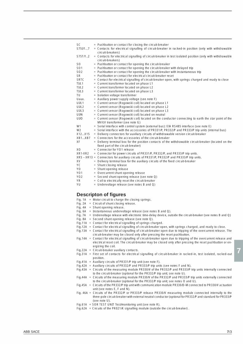
ABB SACE 7/3
7
SC = Pushbutton or contact for closing the circuit-breaker S75I/1...7 = Contacts for electrical signalling of circuit-breaker in racked-in position (only with withdrawable
circuit-breakers)S75T/1..2 = Contacts for electrical signalling of circuit-breaker in test isolated position (only with withdrawable
circuit-breakers)SO = Pushbutton or contact for opening the circuit-breakerSO1 = Pushbutton or contact for opening the circuit-breaker with delayed tripSO2 = Pushbutton or contact for opening the circuit-breaker with instantaneous tripSR = Pushbutton or contact for electrical circuit-breaker resetSRTC = Contact for electrical signalling of circuit-breaker open, with springs charged and ready to close TI/L1 = Current transformer located on phase L1TI/L2 = Current transformer located on phase L2TI/L3 = Current transformer located on phase L3TU = Isolation voltage transformerUaux. = Auxiliary power supply voltage (see note F)UI/L1 = Current sensor (Rogowski coil) located on phase L1UI/L2 = Current sensor (Rogowski coil) located on phase L2UI/L3 = Current sensor (Rogowski coil) located on phase L3UI/N = Current sensor (Rogowski coil) located on neutralUI/O = Current sensor (Rogowski coil) located on the conductor connecting to earth the star point of the
MV/LV transformer (see note G)W1 = Serial interface with control system (external bus): EIA RS485 interface (see note E)W2 = Serial interface with the accessories of PR331/P, PR332/P and PR333/P trip units (internal bus)X12...X15 = Delivery connectors for auxiliary circuits of withdrawable version circuit-breakerXB1...XB7 = Connectors for the accessories of the circuit-breakerXF = Delivery terminal box for the position contacts of the withdrawable circuit-breaker (located on the
fi xed part of the circuit-breaker)XO = Connector for YO1 releaseXR1-XR2 = Connector for power circuits of PR331/P, PR332/P, and PR333/P trip units.XR5 – XR13 = Connectors for auxiliary circuits of PR331/P, PR332/P and PR333/P trip units.XV = Delivery terminal box for the auxiliary circuits of the fi xed circuit-breakerYC = Shunt closing releaseYO = Shunt opening releaseYO1 = Overcurrent shunt opening releaseYO2 = Second shunt opening release (see note Q)YR = Coil to electrically reset the circuit-breakerYU = Undervoltage release (see notes B and Q)
Descripton of fi gures Fig. 1A = Motor circuit to charge the closing springs.Fig. 2A = Circuit of shunt closing release.Fig. 4A = Shunt opening release.Fig. 6A = Instantaneous undervoltage release (see notes B and Q).Fig. 7A = Undervoltage release with electronic time-delay device, outside the circuit-breaker (see notes B and Q)Fig. 8A = Second shunt opening release (see note Q).Fig.11A = Contact for electrical signalling of springs charged.Fig.12A = Contact for electrical signalling of circuit-breaker open, with springs charged, and ready to close. Fig.13A = Contact for electrical signalling of circuit-breaker open due to tripping of the overcurrent release. The
circuit-breaker may be closed only after pressing the reset pushbutton.Fig.14A = Contact for electrical signalling of circuit-breaker open due to tripping of the overcurrent release and
electrical reset coil. The circuit-breaker may be closed only after pressing the reset pushbutton or en-ergizing the coil.
Fig.22A = Circuit-breaker auxiliary contacts.Fig.31A = First set of contacts for electrical signalling of circuit-breaker in racked-in, test isolated, racked-out
position.Fig.41A = Auxiliary circuits of PR331/P trip unit (see note F).Fig.42A = Auxiliary circuits of PR332/P and PR333/P trip units (see notes F and N).Fig.43A = Circuits of the measuring module PR330/V of the PR332/P and PR333/P trip units internally connected
to the circuit-breaker (optional for the PR332/P trip unit; see note U).Fig.44A = Circuits of the measuring module PR330/V of the PR332/P and PR333/P trip units externally connected
to the circuit-breaker (optional for the PR332/P trip unit; see notes O and U).Fig.45A = Circuits of the PR332/P trip unit with communication module PR330/D-M connected to PR330/V actuation
unit (see notes E, F and N).Fig. 46A = Circuits of the PR332/P or PR333/P release PR330/V measuring module connected internally to the
three-pole circuit-breaker with external neutral conductor (optional for PR332/P and standard for PR333/P (see note U).
Fig.61A = SOR TEST UNIT Test/monitoring unit (see note R).Fig.62A = Circuits of the PR021/K signalling module (outside the circuit-breaker) .
X1_cap_7_01.indd 3X1_cap_7_01.indd 3 3-04-2007 17:14:403-04-2007 17:14:40
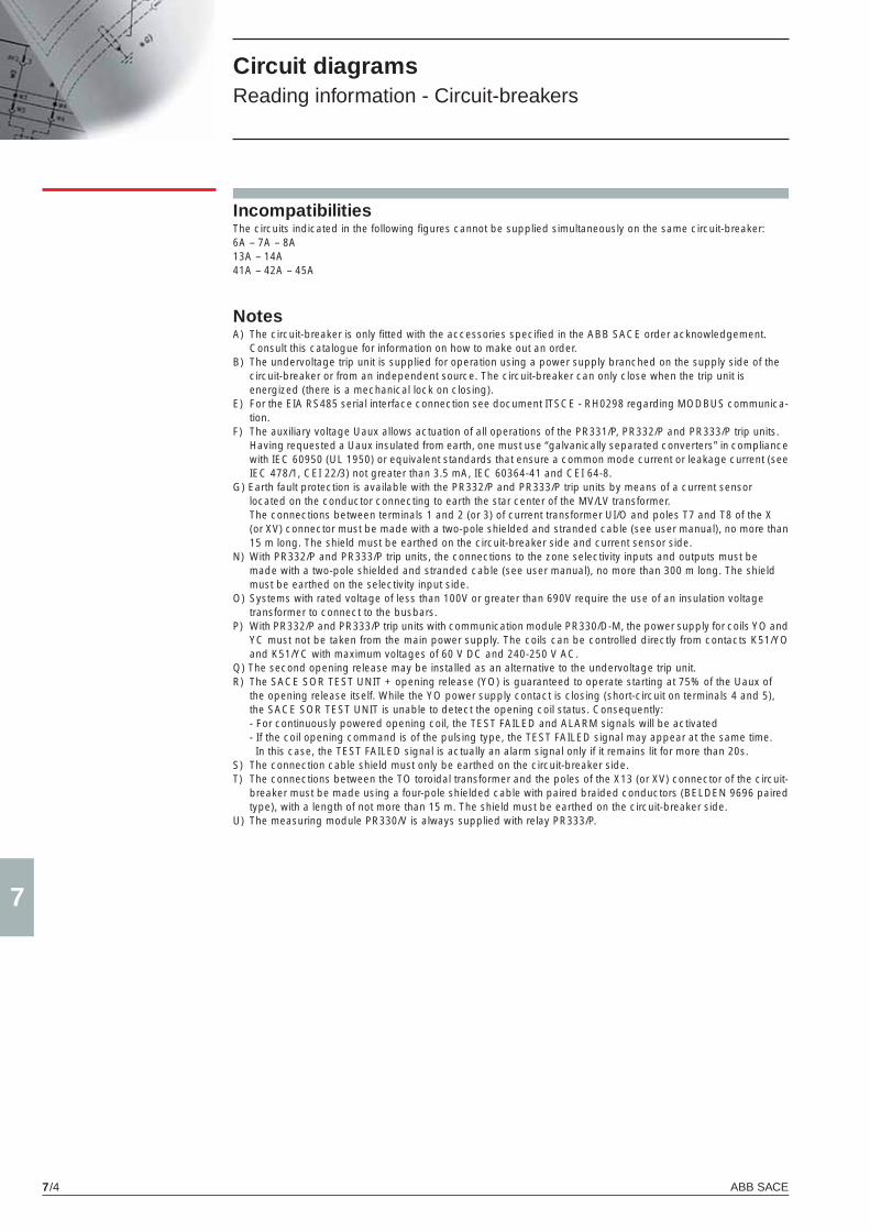
ABB SACE7/4
7
Circuit diagrams Reading information - Circuit-breakers
NotesA) The circuit-breaker is only fi tted with the accessories specifi ed in the ABB SACE order acknowledgement. Consult this catalogue for information on how to make out an order.B) The undervoltage trip unit is supplied for operation using a power supply branched on the supply side of the circuit-breaker or from an independent source. The circuit-breaker can only close when the trip unit is energized (there is a mechanical lock on closing).E) For the EIA RS485 serial interface connection see document ITSCE - RH0298 regarding MODBUS communica-
tion.F) The auxiliary voltage Uaux allows actuation of all operations of the PR331/P, PR332/P and PR333/P trip units. Having requested a Uaux insulated from earth, one must use “galvanically separated converters” in compliance
with IEC 60950 (UL 1950) or equivalent standards that ensure a common mode current or leakage current (see IEC 478/1, CEI 22/3) not greater than 3.5 mA, IEC 60364-41 and CEI 64-8.
G) Earth fault protection is available with the PR332/P and PR333/P trip units by means of a current sensor located on the conductor connecting to earth the star center of the MV/LV transformer. The connections between terminals 1 and 2 (or 3) of current transformer UI/O and poles T7 and T8 of the X (or XV) connector must be made with a two-pole shielded and stranded cable (see user manual), no more than
15 m long. The shield must be earthed on the circuit-breaker side and current sensor side.N) With PR332/P and PR333/P trip units, the connections to the zone selectivity inputs and outputs must be made with a two-pole shielded and stranded cable (see user manual), no more than 300 m long. The shield must be earthed on the selectivity input side.O) Systems with rated voltage of less than 100V or greater than 690V require the use of an insulation voltage transformer to connect to the busbars.P) With PR332/P and PR333/P trip units with communication module PR330/D-M, the power supply for coils YO and
YC must not be taken from the main power supply. The coils can be controlled directly from contacts K51/YO and K51/YC with maximum voltages of 60 V DC and 240-250 V AC.
Q) The second opening release may be installed as an alternative to the undervoltage trip unit.R) The SACE SOR TEST UNIT + opening release (YO) is guaranteed to operate starting at 75% of the Uaux of
the opening release itself. While the YO power supply contact is closing (short-circuit on terminals 4 and 5), the SACE SOR TEST UNIT is unable to detect the opening coil status. Consequently:
- For continuously powered opening coil, the TEST FAILED and ALARM signals will be activated - If the coil opening command is of the pulsing type, the TEST FAILED signal may appear at the same time.
In this case, the TEST FAILED signal is actually an alarm signal only if it remains lit for more than 20s.S) The connection cable shield must only be earthed on the circuit-breaker side.T) The connections between the TO toroidal transformer and the poles of the X13 (or XV) connector of the circuit-
breaker must be made using a four-pole shielded cable with paired braided conductors (BELDEN 9696 paired type), with a length of not more than 15 m. The shield must be earthed on the circuit-breaker side.
U) The measuring module PR330/V is always supplied with relay PR333/P.
IncompatibilitiesThe circuits indicated in the following fi gures cannot be supplied simultaneously on the same circuit-breaker:6A – 7A – 8A13A – 14A41A – 42A – 45A
X1_cap_7_01.indd 4X1_cap_7_01.indd 4 3-04-2007 17:14:403-04-2007 17:14:40
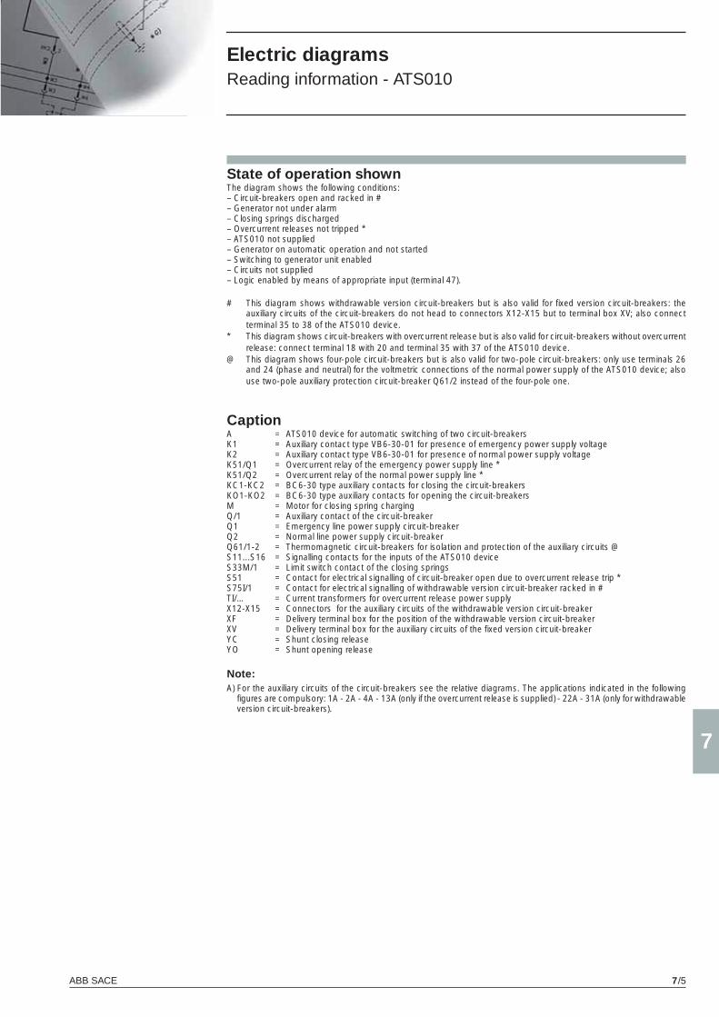
ABB SACE 7/5
7
Electric diagramsReading information - ATS010
State of operation shownThe diagram shows the following conditions:– Circuit-breakers open and racked in #– Generator not under alarm– Closing springs discharged– Overcurrent releases not tripped *– ATS010 not supplied– Generator on automatic operation and not started– Switching to generator unit enabled– Circuits not supplied– Logic enabled by means of appropriate input (terminal 47).
# This diagram shows withdrawable version circuit-breakers but is also valid for fi xed version circuit-breakers: the auxiliary circuits of the circuit-breakers do not head to connectors X12-X15 but to terminal box XV; also connect terminal 35 to 38 of the ATS010 device.
* This diagram shows circuit-breakers with overcurrent release but is also valid for circuit-breakers without overcurrent release: connect terminal 18 with 20 and terminal 35 with 37 of the ATS010 device.
@ This diagram shows four-pole circuit-breakers but is also valid for two-pole circuit-breakers: only use terminals 26 and 24 (phase and neutral) for the voltmetric connections of the normal power supply of the ATS010 device; also use two-pole auxiliary protection circuit-breaker Q61/2 instead of the four-pole one.
CaptionA = ATS010 device for automatic switching of two circuit-breakersK1 = Auxiliary contact type VB6-30-01 for presence of emergency power supply voltageK2 = Auxiliary contact type VB6-30-01 for presence of normal power supply voltageK51/Q1 = Overcurrent relay of the emergency power supply line *K51/Q2 = Overcurrent relay of the normal power supply line *KC1-KC2 = BC6-30 type auxiliary contacts for closing the circuit-breakersKO1-KO2 = BC6-30 type auxiliary contacts for opening the circuit-breakersM = Motor for closing spring chargingQ/1 = Auxiliary contact of the circuit-breakerQ1 = Emergency line power supply circuit-breaker Q2 = Normal line power supply circuit-breaker Q61/1-2 = Thermomagnetic circuit-breakers for isolation and protection of the auxiliary circuits @S11...S16 = Signalling contacts for the inputs of the ATS010 deviceS33M/1 = Limit switch contact of the closing springsS51 = Contact for electrical signalling of circuit-breaker open due to overcurrent release trip *S75I/1 = Contact for electrical signalling of withdrawable version circuit-breaker racked in #TI/… = Current transformers for overcurrent release power supplyX12-X15 = Connectors for the auxiliary circuits of the withdrawable version circuit-breaker XF = Delivery terminal box for the position of the withdrawable version circuit-breakerXV = Delivery terminal box for the auxiliary circuits of the fi xed version circuit-breaker YC = Shunt closing releaseYO = Shunt opening release
Note:A) For the auxiliary circuits of the circuit-breakers see the relative diagrams. The applications indicated in the following
fi gures are compulsory: 1A - 2A - 4A - 13A (only if the overcurrent release is supplied) - 22A - 31A (only for withdrawable version circuit-breakers).
X1_cap_7_01.indd 5X1_cap_7_01.indd 5 3-04-2007 17:14:413-04-2007 17:14:41
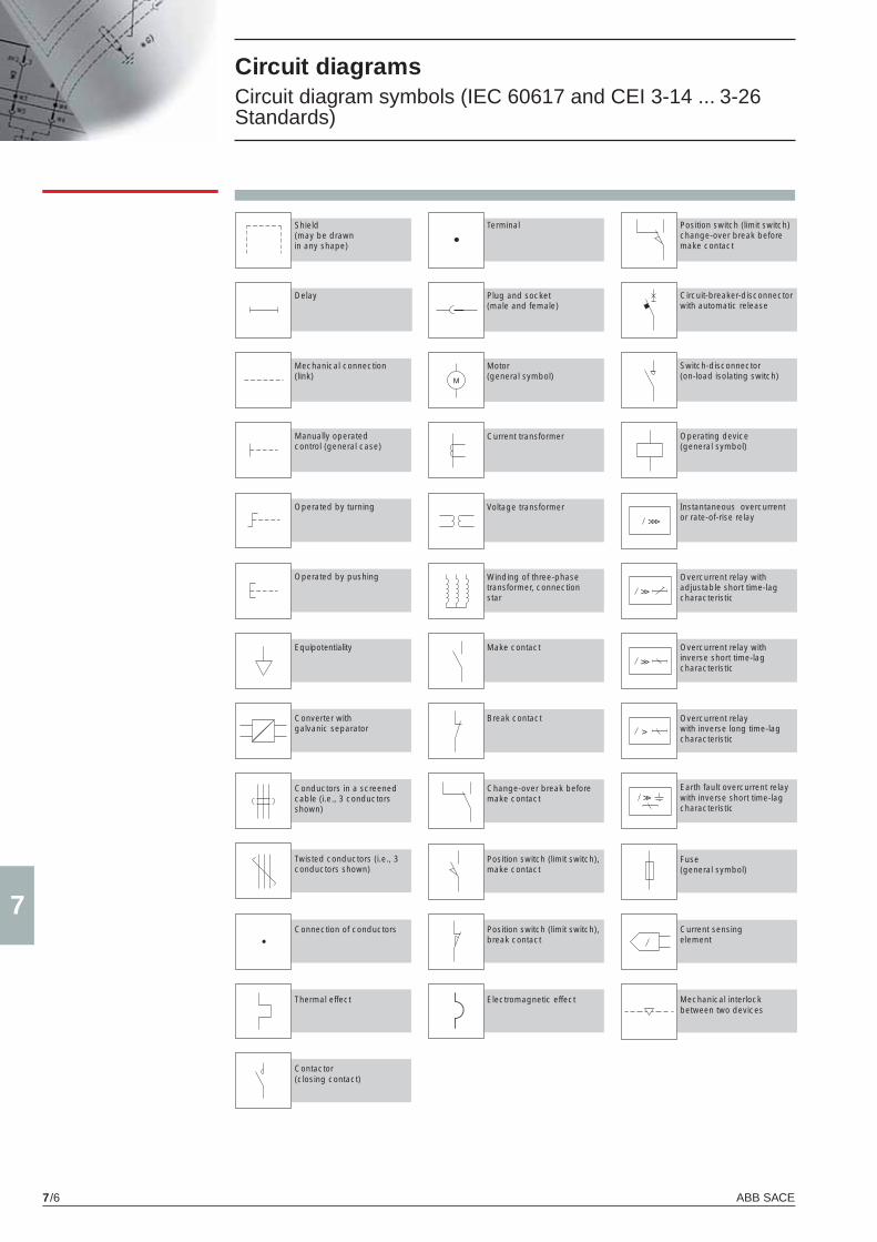
ABB SACE7/6
7
Circuit diagrams Circuit diagram symbols (IEC 60617 and CEI 3-14 ... 3-26 Standards)
Shield (may be drawn in any shape)
Delay
Mechanical connection(link)
Manually operated control (general case)
Operated by turning
Operated by pushing
Equipotentiality
Terminal
Plug and socket (male and female)
Motor (general symbol)
Current transformer
Voltage transformer
Winding of three-phase transformer, connection star
Position switch (limit switch) change-over break before make contact
Circuit-breaker-disconnector with automatic release
Switch-disconnector (on-load isolating switch)
Operating device(general symbol)
Instantaneous overcurrent or rate-of-rise relay
Overcurrent relay with adjustable short time-lag characteristic
Converter with galvanic separator
Conductors in a screened cable (i.e., 3 conductors shown)
Twisted conductors (i.e., 3 conductors shown)
Connection of conductors
Make contact
Break contact
Change-over break before make contact
Position switch (limit switch), make contact
Position switch (limit switch), break contact
Overcurrent relay with inverse short time-lag characteristic
Overcurrent relay with inverse long time-lag characteristic
Earth fault overcurrent relay with inverse short time-lag characteristic
Fuse (general symbol)
Current sensing element
Thermal effect Electromagnetic effect Mechanical interlock between two devices
Contactor(closing contact)
X1_cap_7_01.indd 6X1_cap_7_01.indd 6 3-04-2007 17:14:413-04-2007 17:14:41

ABB SACE 7/7
7
Operating status
Circuit diagrams Circuit-breakers
Clamp not connected
Three-pole circuit-breaker with PR331/P, PR332/P or PR333/P electronic trip unit Three- or four-pole switch-disconnector
Four-pole circuit-breaker with PR331/P, PR332/P or PR333P electronic trip unit
Three-pole circuit-breaker with PR331/P, PR332/P or PR333P electronic trip unit
X1_cap_7_01.indd 7X1_cap_7_01.indd 7 6-04-2007 9:02:396-04-2007 9:02:39
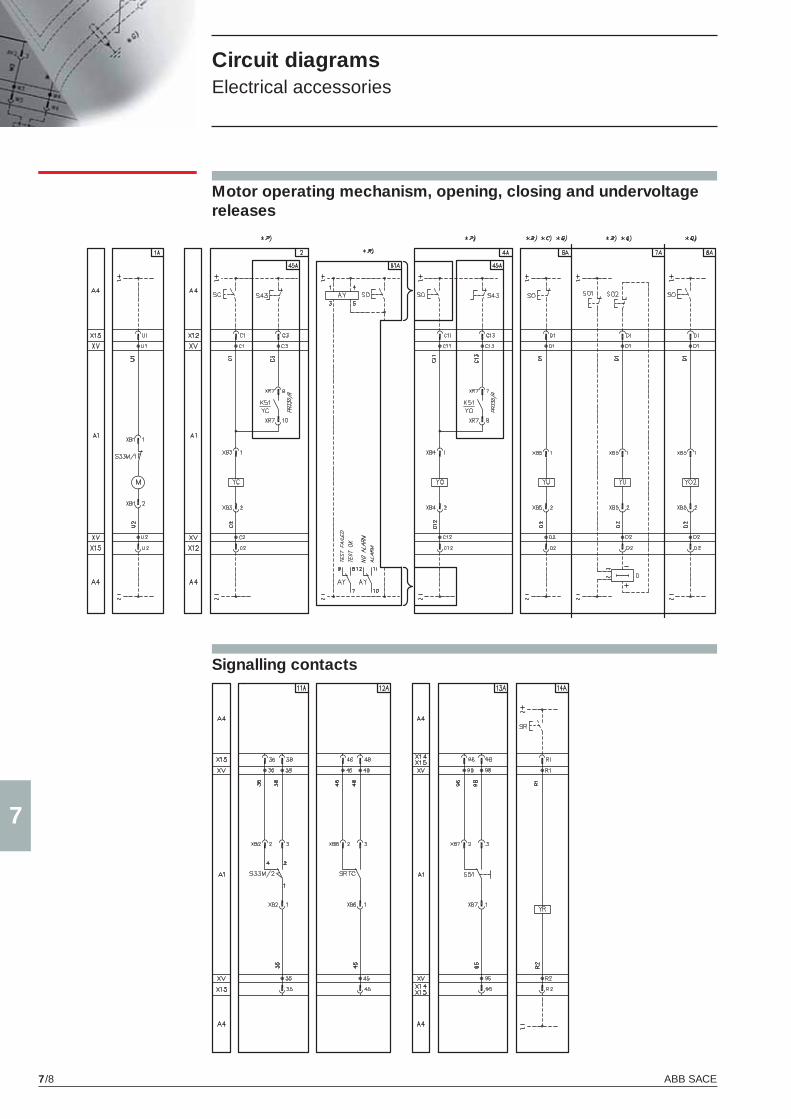
ABB SACE7/8
7
Circuit diagrams Electrical accessories
Motor operating mechanism, opening, closing and undervoltage releases
Signalling contacts
X1_cap_7_01.indd 8X1_cap_7_01.indd 8 3-04-2007 17:14:423-04-2007 17:14:42
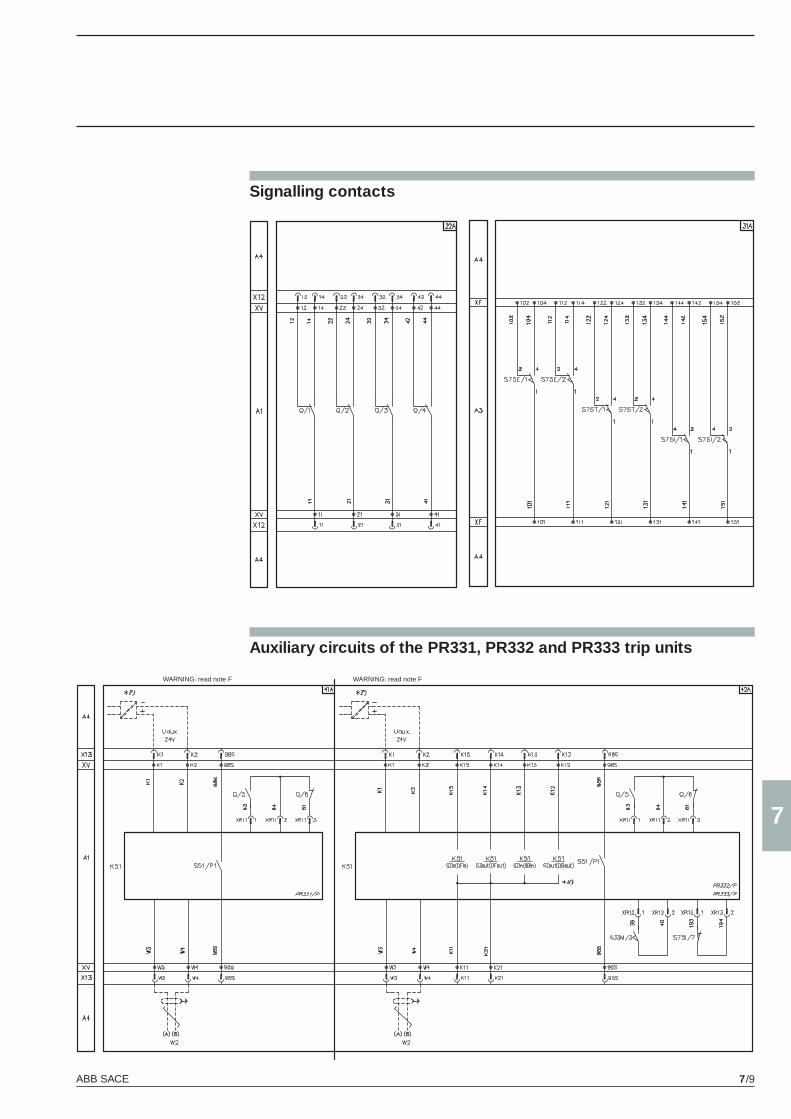
ABB SACE 7/9
7
Auxiliary circuits of the PR331, PR332 and PR333 trip units
Signalling contacts
WARNING: read note FWARNING: read note F
X1_cap_7_01.indd 9X1_cap_7_01.indd 9 3-04-2007 17:14:423-04-2007 17:14:42
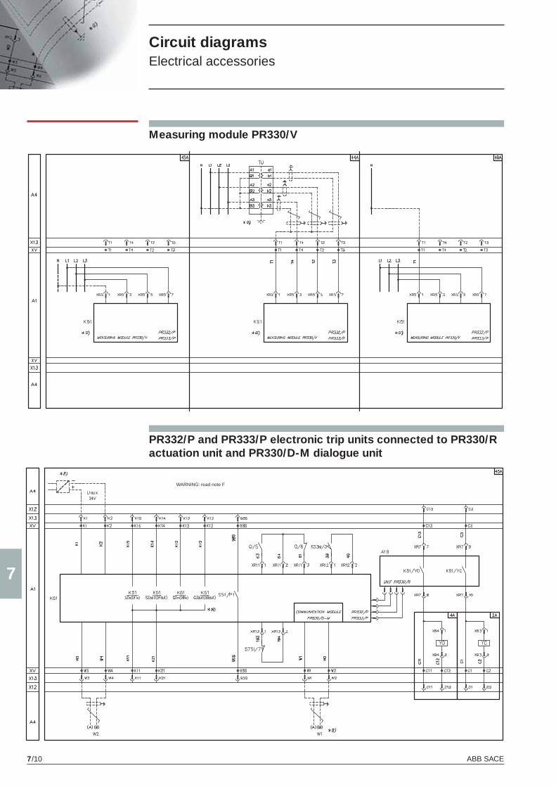
ABB SACE7/10
7
PR332/P and PR333/P electronic trip units connected to PR330/R actuation unit and PR330/D-M dialogue unit
Measuring module PR330/V
WARNING: read note F
Circuit diagrams Electrical accessories
X1_cap_7_01.indd 10X1_cap_7_01.indd 10 3-04-2007 17:14:433-04-2007 17:14:43
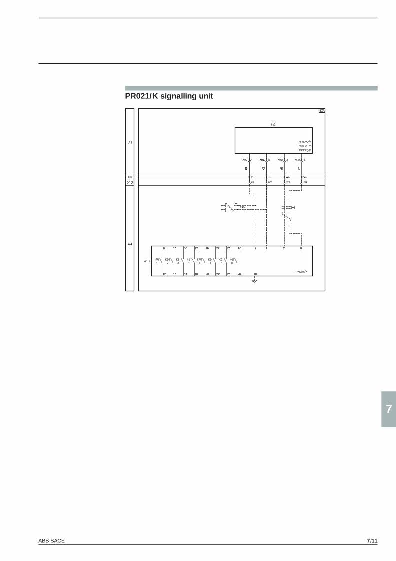
ABB SACE 7/11
7
PR021/K signalling unit
X1_cap_7_01.indd 11X1_cap_7_01.indd 11 3-04-2007 17:14:433-04-2007 17:14:43
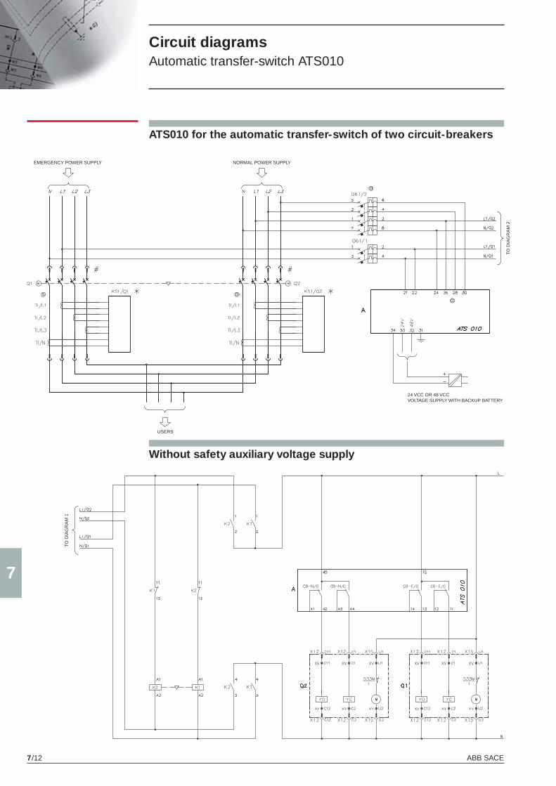
ABB SACE7/12
7
Circuit diagrams Automatic transfer-switch ATS010
ATS010 for the automatic transfer-switch of two circuit-breakers
EMERGENCY POWER SUPPLY NORMAL POWER SUPPLY
USERS
24 VCC OR 48 VCCVOLTAGE SUPPLY WITH BACKUP BATTERY
TO D
IAG
RA
M 2
Without safety auxiliary voltage supply
TO D
IAG
RA
M 1
X1_cap_7_01.indd 12X1_cap_7_01.indd 12 3-04-2007 17:14:433-04-2007 17:14:43
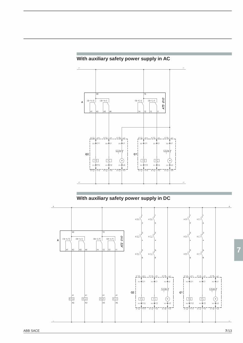
ABB SACE 7/13
7
With auxiliary safety power supply in AC
With auxiliary safety power supply in DC
X1_cap_7_01.indd 13X1_cap_7_01.indd 13 3-04-2007 17:14:433-04-2007 17:14:43
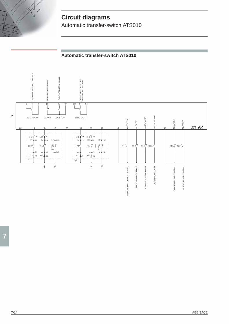
ABB SACE7/14
7
Circuit diagrams Automatic transfer-switch ATS010
Automatic transfer-switch ATS010
GE
NE
RAT
OR
STA
RT
CO
NT
RO
L
ATS
010
ALA
RM
SIG
NA
L
LOG
IC A
CT
IVAT
ED
SIG
NA
L
DIS
CO
NN
EC
T C
ON
TR
OL
NO
N-P
RIO
RIT
Y L
OA
DS
RE
MO
TE
SW
ITC
HIN
G C
ON
TR
OL
SW
ITC
HIN
G IN
TE
RFA
CE
AU
TOM
ATIC
GE
NE
RAT
OR
GE
NE
RAT
OR
ALA
RM
LOG
IC E
NA
BLI
NG
CO
NT
RO
L
ATS
010
RE
SE
T C
ON
TR
OL
X1_cap_7_01.indd 14X1_cap_7_01.indd 14 3-04-2007 17:14:433-04-2007 17:14:43

X1_cap_7_01.indd 15X1_cap_7_01.indd 15 3-04-2007 17:14:443-04-2007 17:14:44

X1_cap_8_00.indd 2X1_cap_8_00.indd 2 4-04-2007 10:00:504-04-2007 10:00:50
8
ABB SACE 8/1
Ordering codes
Contents
General information .......................................................................................................... 8/2
Instruction for ordering ..................................................................................................... 8/3
SACE Emax X1 automatic circuit-breakers
SACE Emax X1 .................................................................................................................... 8/5
SACE Emax X1 switch-disconnectors
SACE Emax X1/MS .............................................................................................................. 8/11
SACE Emax X1 circuit-breakers for applications up to 1000V AC
SACE Emax X1/E ................................................................................................................. 8/12
SACE Emax X1 switch-disconnectors for applications up to 1000V AC
SACE Emax X1/E MS .......................................................................................................... 8/13
Fixed parts and conversion kits for fi xed circuit-breaker and fi xed parts ................... 8/14
SACE Emax X1 accessories ............................................................................................. 8/15
X1_cap_8_00.indd 3X1_cap_8_00.indd 3 4-04-2007 10:00:544-04-2007 10:00:54

ABB SACE8/2
8
Ordering codes General information
Abbreviations used to describe the apparatus
HR/VR Adjustable terminals (horizontal/vertical) F Fixed W Withdrawable MP Moving part for withdrawable circuit-breakers FP Fixed part for withdrawable circuit-breakers
PR331/P PR331/P Electronic trip unit (LI, LSI, LSIG functions) PR332/P PR332/P Electronic trip unit (LSI, LSIG, LSIRc functions) PR333/P PR333/P Electronic trip unit (LSI, LSIG functions)
Functions: L Protection against overload with long inverse time-delay trip S Selective protection against short-circuit with short inverse or defi nite time-delay trip I Protection against instantaneous short-circuit with adjustable trip current threshold G Protection against earth faults Rc Protection against residual current earth faults
Iu Rated uninterrupted current of the circuit-breaker In Rated current of the electronic trip unit current transformers Icu Rated ultimate short-circuit breaking capacity Icw Rated short-time withstand current AC AC applications DC DC applications /MS Switch-disconnector
VR = Vertical rear terminals
EF = Front extended terminals
HR = Horizontal rear terminals
F = Front terminals
ES = Front spread terminals
RS = Rear spread terminals
X1_cap_8_02_14.indd 2X1_cap_8_02_14.indd 2 4-04-2007 10:01:274-04-2007 10:01:27
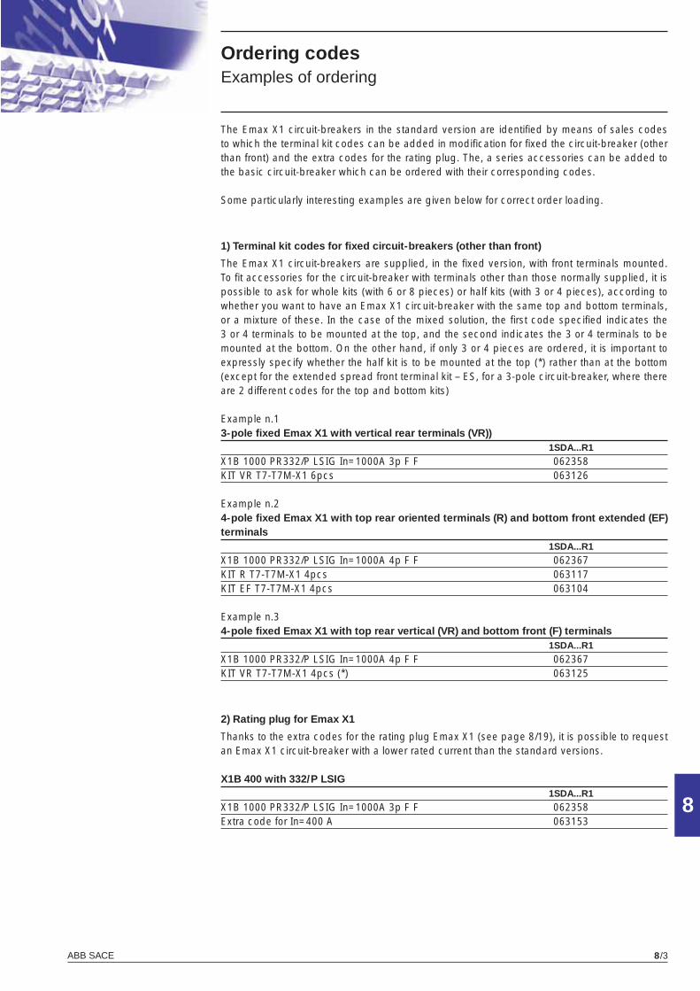
ABB SACE 8/3
8
Ordering codesExamples of ordering
The Emax X1 circuit-breakers in the standard version are identifi ed by means of sales codes to which the terminal kit codes can be added in modifi cation for fi xed the circuit-breaker (other than front) and the extra codes for the rating plug. The, a series accessories can be added to the basic circuit-breaker which can be ordered with their corresponding codes.
Some particularly interesting examples are given below for correct order loading.
1) Terminal kit codes for fi xed circuit-breakers (other than front)
The Emax X1 circuit-breakers are supplied, in the fi xed version, with front terminals mounted. To fi t accessories for the circuit-breaker with terminals other than those normally supplied, it is possible to ask for whole kits (with 6 or 8 pieces) or half kits (with 3 or 4 pieces), according to whether you want to have an Emax X1 circuit-breaker with the same top and bottom terminals, or a mixture of these. In the case of the mixed solution, the fi rst code specifi ed indicates the 3 or 4 terminals to be mounted at the top, and the second indicates the 3 or 4 terminals to be mounted at the bottom. On the other hand, if only 3 or 4 pieces are ordered, it is important to expressly specify whether the half kit is to be mounted at the top (*) rather than at the bottom (except for the extended spread front terminal kit – ES, for a 3-pole circuit-breaker, where there are 2 different codes for the top and bottom kits)
Example n.13-pole fi xed Emax X1 with vertical rear terminals (VR)) 1SDA...R1
X1B 1000 PR332/P LSIG In=1000A 3p F F 062358 KIT VR T7-T7M-X1 6pcs 063126
Example n.24-pole fi xed Emax X1 with top rear oriented terminals (R) and bottom front extended (EF) terminals 1SDA...R1
X1B 1000 PR332/P LSIG In=1000A 4p F F 062367 KIT R T7-T7M-X1 4pcs 063117KIT EF T7-T7M-X1 4pcs 063104
Example n.34-pole fi xed Emax X1 with top rear vertical (VR) and bottom front (F) terminals 1SDA...R1
X1B 1000 PR332/P LSIG In=1000A 4p F F 062367 KIT VR T7-T7M-X1 4pcs (*) 063125
2) Rating plug for Emax X1
Thanks to the extra codes for the rating plug Emax X1 (see page 8/19), it is possible to request an Emax X1 circuit-breaker with a lower rated current than the standard versions.
X1B 400 with 332/P LSIG 1SDA...R1
X1B 1000 PR332/P LSIG In=1000A 3p F F 062358 Extra code for In=400 A 063153
X1_cap_8_02_14.indd 3X1_cap_8_02_14.indd 3 4-04-2007 10:01:284-04-2007 10:01:28
ABB SACE8/4
8
Ordering codesExamples of ordering
3) Sliding contacts for Emax X1 in withdrawable version
The electrical accessories of Emax X1 in the withdrawable version must be fi tted with special sliding contacts for the moving part and for the fi xed part, as shown in the table on page 4/14.
Example n.1X1B 1000 PR331/P in withdrawable version, shunt opening release 1SDA...R1
POS1 X1B 1000 PR331/P LSI In=1000A 3p W MP 062372 Shunt opening release SOR 240…250 V AC/DC 062070 POS2 Fixed part for withdrawable 3p X1 EF-EF 062045 Right-hand block – FP X1 062169 Central block – FP X1 062168
Example n.2X1B 1000 PR331/P in withdrawable version, trip reset 1SDA...R1
POS1 X1B 1000 PR331/P LSI In=1000A 3p W MP 062372 TRIP RESET X1 24...30 V AC/DC 063554 POS2 Fixed part for X1 withdrawable 3p EF-EF 062045 Right-hand block – FP X1 062169 Central block – FP X1 062168 Left-hand block – FP X1 062164
4) Motorisation for Emax X1
For motorisation of Emax X1, the circuit-breaker must be fi tted with a spring charging geared motor, shunt opening release and shunt closing release.
X1B 1000 motorised PR332/P 1SDA...R1
X1B 1000 PR332/P LSIG In=1000A 3p F F 062358 Spring charging geared motor 220…250 V AC/DC 062116Shunt opening release SOR 240…250 V AC/DC 062070 Shunt opening and closing release SCR 240…250 V AC/DC 062081
X1_cap_8_02_14.indd 4X1_cap_8_02_14.indd 4 6-04-2007 9:08:136-04-2007 9:08:13
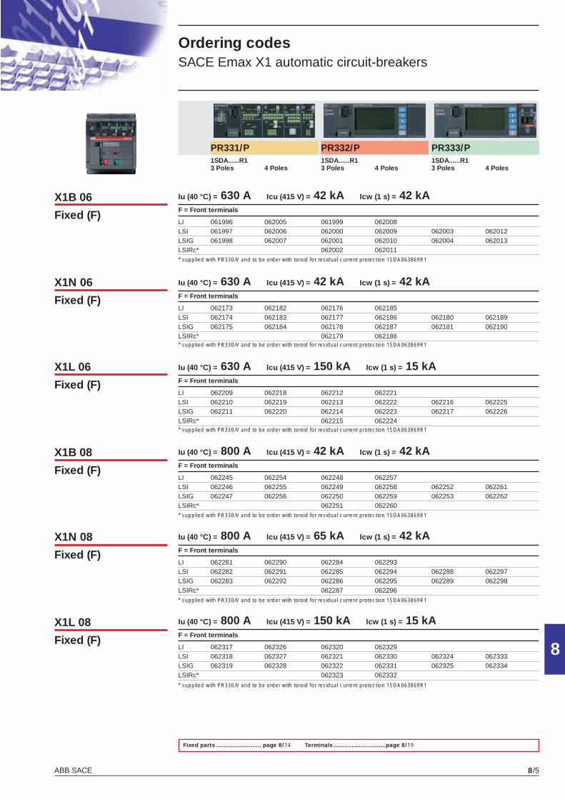
ABB SACE 8/5
8
Ordering codes SACE Emax X1 automatic circuit-breakers
PR331/P PR332/P PR333/P 1SDA......R1 1SDA......R1 1SDA......R1 3 Poles 4 Poles 3 Poles 4 Poles 3 Poles 4 Poles Iu (40 °C) = 630 A Icu (415 V) = 42 kA Icw (1 s) = 42 kAF = Front terminals
LI 061996 062005 061999 062008 LSI 061997 062006 062000 062009 062003 062012LSIG 061998 062007 062001 062010 062004 062013LSIRc* 062002 062011
Iu (40 °C) = 630 A Icu (415 V) = 42 kA Icw (1 s) = 42 kAF = Front terminals
LI 062173 062182 062176 062185 LSI 062174 062183 062177 062186 062180 062189LSIG 062175 062184 062178 062187 062181 062190LSIRc* 062179 062188
Iu (40 °C) = 630 A Icu (415 V) = 150 kA Icw (1 s) = 15 kAF = Front terminals
LI 062209 062218 062212 062221 LSI 062210 062219 062213 062222 062216 062225LSIG 062211 062220 062214 062223 062217 062226LSIRc* 062215 062224
Iu (40 °C) = 800 A Icu (415 V) = 42 kA Icw (1 s) = 42 kAF = Front terminals
LI 062245 062254 062248 062257 LSI 062246 062255 062249 062258 062252 062261LSIG 062247 062256 062250 062259 062253 062262LSIRc* 062251 062260
Iu (40 °C) = 800 A Icu (415 V) = 65 kA Icw (1 s) = 42 kAF = Front terminals
LI 062281 062290 062284 062293 LSI 062282 062291 062285 062294 062288 062297LSIG 062283 062292 062286 062295 062289 062298LSIRc* 062287 062296
Iu (40 °C) = 800 A Icu (415 V) = 150 kA Icw (1 s) = 15 kAF = Front terminals
LI 062317 062326 062320 062329 LSI 062318 062327 062321 062330 062324 062333LSIG 062319 062328 062322 062331 062325 062334LSIRc* 062323 062332
Fixed parts ......................... page 8/14 Terminals .............................page 8/19
X1B 06
Fixed (F)
X1N 06
Fixed (F)
X1L 06
Fixed (F)
X1B 08
Fixed (F)
X1N 08
Fixed (F)
X1L 08
Fixed (F)
* supplied with PR330/V and to be order with toroid for residual current protection 1SDA063869R1
* supplied with PR330/V and to be order with toroid for residual current protection 1SDA063869R1
* supplied with PR330/V and to be order with toroid for residual current protection 1SDA063869R1
* supplied with PR330/V and to be order with toroid for residual current protection 1SDA063869R1
* supplied with PR330/V and to be order with toroid for residual current protection 1SDA063869R1
* supplied with PR330/V and to be order with toroid for residual current protection 1SDA063869R1
X1_cap_8_02_14.indd 5X1_cap_8_02_14.indd 5 4-04-2007 10:01:304-04-2007 10:01:30
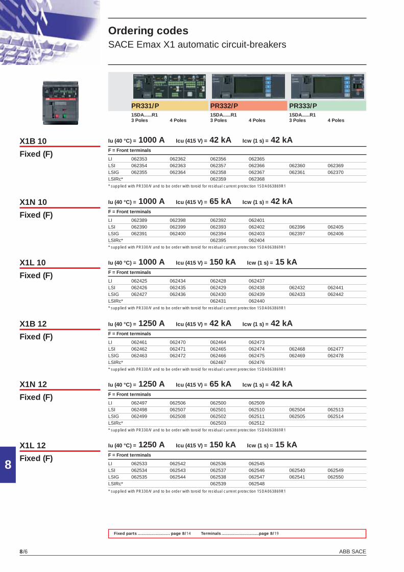
ABB SACE8/6
8
Ordering codes SACE Emax X1 automatic circuit-breakers
X1B 10
Fixed (F)
X1N 10
Fixed (F)
X1L 10
Fixed (F)
X1B 12
Fixed (F)
X1N 12
Fixed (F)
X1L 12
Fixed (F)
Fixed parts ......................... page 8/14 Terminals .............................page 8/19
PR331/P PR332/P PR333/P 1SDA......R1 1SDA......R1 1SDA......R1 3 Poles 4 Poles 3 Poles 4 Poles 3 Poles 4 Poles Iu (40 °C) = 1000 A Icu (415 V) = 42 kA Icw (1 s) = 42 kAF = Front terminals
LI 062353 062362 062356 062365 LSI 062354 062363 062357 062366 062360 062369LSIG 062355 062364 062358 062367 062361 062370LSIRc* 062359 062368
Iu (40 °C) = 1000 A Icu (415 V) = 65 kA Icw (1 s) = 42 kAF = Front terminals
LI 062389 062398 062392 062401 LSI 062390 062399 062393 062402 062396 062405LSIG 062391 062400 062394 062403 062397 062406LSIRc* 062395 062404
Iu (40 °C) = 1000 A Icu (415 V) = 150 kA Icw (1 s) = 15 kA F = Front terminals
LI 062425 062434 062428 062437 LSI 062426 062435 062429 062438 062432 062441LSIG 062427 062436 062430 062439 062433 062442LSIRc* 062431 062440
Iu (40 °C) = 1250 A Icu (415 V) = 42 kA Icw (1 s) = 42 kA F = Front terminals
LI 062461 062470 062464 062473 LSI 062462 062471 062465 062474 062468 062477LSIG 062463 062472 062466 062475 062469 062478LSIRc* 062467 062476
Iu (40 °C) = 1250 A Icu (415 V) = 65 kA Icw (1 s) = 42 kA F = Front terminals
LI 062497 062506 062500 062509 LSI 062498 062507 062501 062510 062504 062513LSIG 062499 062508 062502 062511 062505 062514LSIRc* 062503 062512
Iu (40 °C) = 1250 A Icu (415 V) = 150 kA Icw (1 s) = 15 kA F = Front terminals
LI 062533 062542 062536 062545 LSI 062534 062543 062537 062546 062540 062549LSIG 062535 062544 062538 062547 062541 062550LSIRc* 062539 062548
* supplied with PR330/V and to be order with toroid for residual current protection 1SDA063869R1
* supplied with PR330/V and to be order with toroid for residual current protection 1SDA063869R1
* supplied with PR330/V and to be order with toroid for residual current protection 1SDA063869R1
* supplied with PR330/V and to be order with toroid for residual current protection 1SDA063869R1
* supplied with PR330/V and to be order with toroid for residual current protection 1SDA063869R1
* supplied with PR330/V and to be order with toroid for residual current protection 1SDA063869R1
X1_cap_8_02_14.indd 6X1_cap_8_02_14.indd 6 4-04-2007 10:01:364-04-2007 10:01:36
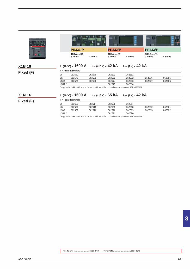
ABB SACE 8/7
8
X1B 16
Fixed (F)
X1N 16
Fixed (F)
Fixed parts ......................... page 8/14 Terminals .............................page 8/19
PR331/P PR332/P PR333/P 1SDA......R1 1SDA......R1 1SDA......R1 3 Poles 4 Poles 3 Poles 4 Poles 3 Poles 4 Poles Iu (40 °C) = 1600 A Icu (415 V) = 42 kA Icw (1 s) = 42 kAF = Front terminals
LI 062569 062578 062572 062581 LSI 062570 062579 062573 062582 062576 062585LSIG 062571 062580 062574 062583 062577 062586LSIRc* 062575 062584
Iu (40 °C) = 1600 A Icu (415 V) = 65 kA Icw (1 s) = 42 kAF = Front terminals
LI 062605 062614 062608 062617 LSI 062606 062615 062609 062618 062612 062621LSIG 062607 062616 062610 062619 062613 062622LSIRc* 062611 062620
* supplied with PR330/V and to be order with toroid for residual current protection 1SDA063869R1
* supplied with PR330/V and to be order with toroid for residual current protection 1SDA063869R1
X1_cap_8_02_14.indd 7X1_cap_8_02_14.indd 7 4-04-2007 10:01:424-04-2007 10:01:42
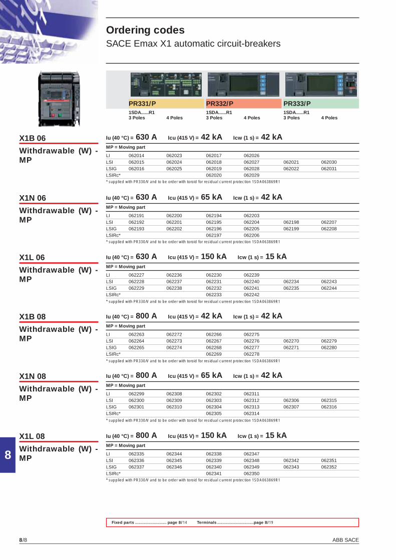
ABB SACE8/8
8
Ordering codes SACE Emax X1 automatic circuit-breakers
X1B 06
Withdrawable (W) - MP
X1N 06
Withdrawable (W) - MP
X1L 06
Withdrawable (W) - MP
X1B 08
Withdrawable (W) - MP
X1N 08
Withdrawable (W) - MP
X1L 08
Withdrawable (W) - MP
Fixed parts ......................... page 8/14 Terminals .............................page 8/19
PR331/P PR332/P PR333/P 1SDA......R1 1SDA......R1 1SDA......R1 3 Poles 4 Poles 3 Poles 4 Poles 3 Poles 4 Poles Iu (40 °C) = 630 A Icu (415 V) = 42 kA Icw (1 s) = 42 kAMP = Moving part
LI 062014 062023 062017 062026 LSI 062015 062024 062018 062027 062021 062030LSIG 062016 062025 062019 062028 062022 062031LSIRc* 062020 062029
Iu (40 °C) = 630 A Icu (415 V) = 65 kA Icw (1 s) = 42 kAMP = Moving part
LI 062191 062200 062194 062203 LSI 062192 062201 062195 062204 062198 062207LSIG 062193 062202 062196 062205 062199 062208LSIRc* 062197 062206
Iu (40 °C) = 630 A Icu (415 V) = 150 kA Icw (1 s) = 15 kA MP = Moving part
LI 062227 062236 062230 062239 LSI 062228 062237 062231 062240 062234 062243LSIG 062229 062238 062232 062241 062235 062244LSIRc* 062233 062242
Iu (40 °C) = 800 A Icu (415 V) = 42 kA Icw (1 s) = 42 kA MP = Moving part
LI 062263 062272 062266 062275 LSI 062264 062273 062267 062276 062270 062279LSIG 062265 062274 062268 062277 062271 062280LSIRc* 062269 062278
Iu (40 °C) = 800 A Icu (415 V) = 65 kA Icw (1 s) = 42 kA MP = Moving part
LI 062299 062308 062302 062311 LSI 062300 062309 062303 062312 062306 062315LSIG 062301 062310 062304 062313 062307 062316LSIRc* 062305 062314
Iu (40 °C) = 800 A Icu (415 V) = 150 kA Icw (1 s) = 15 kA MP = Moving part
LI 062335 062344 062338 062347 LSI 062336 062345 062339 062348 062342 062351LSIG 062337 062346 062340 062349 062343 062352LSIRc* 062341 062350
* supplied with PR330/V and to be order with toroid for residual current protection 1SDA063869R1
* supplied with PR330/V and to be order with toroid for residual current protection 1SDA063869R1
* supplied with PR330/V and to be order with toroid for residual current protection 1SDA063869R1
* supplied with PR330/V and to be order with toroid for residual current protection 1SDA063869R1
* supplied with PR330/V and to be order with toroid for residual current protection 1SDA063869R1
* supplied with PR330/V and to be order with toroid for residual current protection 1SDA063869R1
X1_cap_8_02_14.indd 8X1_cap_8_02_14.indd 8 4-04-2007 10:01:484-04-2007 10:01:48
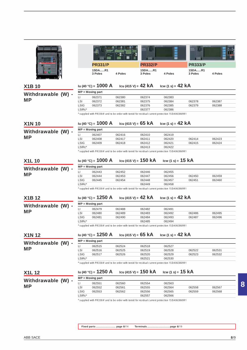
ABB SACE 8/9
8
X1B 10
Withdrawable (W) - MP
X1N 10
Withdrawable (W) - MP
X1L 10
Withdrawable (W) - MP
X1B 12
Withdrawable (W) - MP
X1N 12
Withdrawable (W) - MP
X1L 12
Withdrawable (W) - MP
Fixed parts ......................... page 8/14 Terminals .............................page 8/19
PR331/P PR332/P PR333/P 1SDA......R1 1SDA......R1 1SDA......R1 3 Poles 4 Poles 3 Poles 4 Poles 3 Poles 4 Poles Iu (40 °C) = 1000 A Icu (415 V) = 42 kA Icw (1 s) = 42 kAMP = Moving part
LI 062371 062380 062374 062383 LSI 062372 062381 062375 062384 062378 062387LSIG 062373 062382 062376 062385 062379 062388LSIRc* 062377 062386
Iu (40 °C) = 1000 A Icu (415 V) = 65 kA Icw (1 s) = 42 kAMP = Moving part
LI 062407 062416 062410 062419 LSI 062408 062417 062411 062420 062414 062423LSIG 062409 062418 062412 062421 062415 062424LSIRc* 062413 062422
Iu (40 °C) = 1000 A Icu (415 V) = 150 kA Icw (1 s) = 15 kA MP = Moving part
LI 062443 062452 062446 062455 LSI 062444 062453 062447 062456 062450 062459LSIG 062445 062454 062448 062457 062451 062460LSIRc* 062449 062458
Iu (40 °C) = 1250 A Icu (415 V) = 42 kA Icw (1 s) = 42 kA MP = Moving part
LI 062479 062488 062482 062491 LSI 062480 062489 062483 062492 062486 062495LSIG 062481 062490 062484 062493 062487 062496LSIRc* 062485 062494
Iu (40 °C) = 1250 A Icu (415 V) = 65 kA Icw (1 s) = 42 kA MP = Moving part
LI 062515 062524 062518 062527 LSI 062516 062525 062519 062528 062522 062531LSIG 062517 062526 062520 062529 062523 062532LSIRc* 062521 062530
Iu (40 °C) = 1250 A Icu (415 V) = 150 kA Icw (1 s) = 15 kA MP = Moving part
LI 062551 062560 062554 062563 LSI 062552 062561 062555 062564 062558 062567LSIG 062553 062562 062556 062565 062559 062568LSIRc* 062557 062566
* supplied with PR330/V and to be order with toroid for residual current protection 1SDA063869R1
* supplied with PR330/V and to be order with toroid for residual current protection 1SDA063869R1
* supplied with PR330/V and to be order with toroid for residual current protection 1SDA063869R1
* supplied with PR330/V and to be order with toroid for residual current protection 1SDA063869R1
* supplied with PR330/V and to be order with toroid for residual current protection 1SDA063869R1
* supplied with PR330/V and to be order with toroid for residual current protection 1SDA063869R1
X1_cap_8_02_14.indd 9X1_cap_8_02_14.indd 9 4-04-2007 10:01:544-04-2007 10:01:54
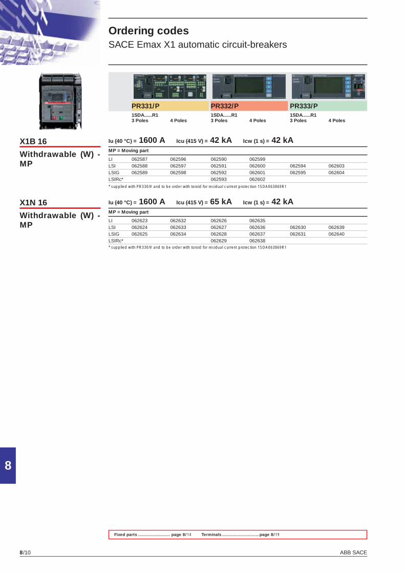
ABB SACE8/10
8
Ordering codes SACE Emax X1 automatic circuit-breakers
X1B 16
Withdrawable (W) - MP
X1N 16
Withdrawable (W) - MP
Fixed parts ......................... page 8/14 Terminals .............................page 8/19
PR331/P PR332/P PR333/P 1SDA......R1 1SDA......R1 1SDA......R1 3 Poles 4 Poles 3 Poles 4 Poles 3 Poles 4 Poles Iu (40 °C) = 1600 A Icu (415 V) = 42 kA Icw (1 s) = 42 kAMP = Moving part
LI 062587 062596 062590 062599 LSI 062588 062597 062591 062600 062594 062603LSIG 062589 062598 062592 062601 062595 062604LSIRc* 062593 062602
Iu (40 °C) = 1600 A Icu (415 V) = 65 kA Icw (1 s) = 42 kAMP = Moving part
LI 062623 062632 062626 062635 LSI 062624 062633 062627 062636 062630 062639LSIG 062625 062634 062628 062637 062631 062640LSIRc* 062629 062638
* supplied with PR330/V and to be order with toroid for residual current protection 1SDA063869R1
* supplied with PR330/V and to be order with toroid for residual current protection 1SDA063869R1
X1_cap_8_02_14.indd 10X1_cap_8_02_14.indd 10 4-04-2007 10:02:014-04-2007 10:02:01
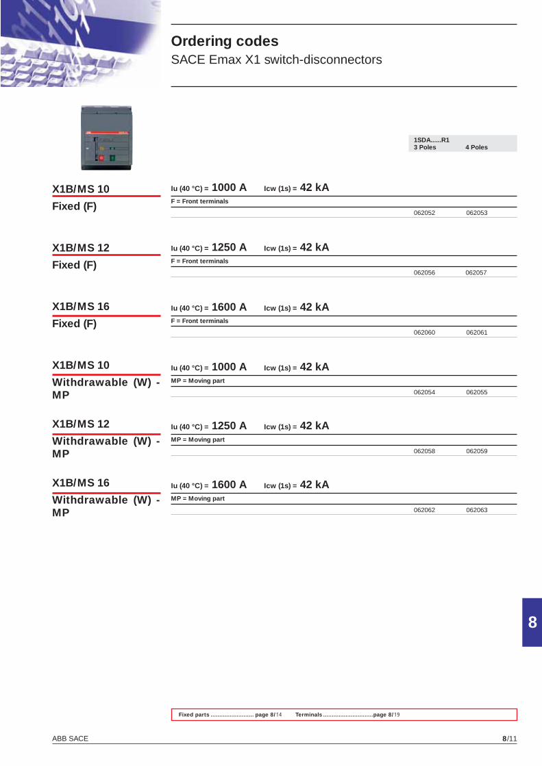
ABB SACE 8/11
8
Ordering codes SACE Emax X1 switch-disconnectors
1SDA......R1 3 Poles 4 Poles
X1B/MS 10
Fixed (F)
X1B/MS 12
Fixed (F)
X1B/MS 12
Withdrawable (W) - MP
X1B/MS 16
Withdrawable (W) - MP
X1B/MS 16
Fixed (F)
X1B/MS 10
Withdrawable (W) - MP
Fixed parts ......................... page 8/14 Terminals .............................page 8/19
Iu (40 °C) = 1000 A Icw (1s) = 42 kA F = Front terminals
062052 062053
Iu (40 °C) = 1250 A Icw (1s) = 42 kAF = Front terminals
062056 062057
Iu (40 °C) = 1600 A Icw (1s) = 42 kA F = Front terminals
062060 062061
Iu (40 °C) = 1000 A Icw (1s) = 42 kAMP = Moving part
062054 062055
Iu (40 °C) = 1250 A Icw (1s) = 42 kAMP = Moving part
062058 062059
Iu (40 °C) = 1600 A Icw (1s) = 42 kAMP = Moving part
062062 062063
X1_cap_8_02_14.indd 11X1_cap_8_02_14.indd 11 4-04-2007 10:02:074-04-2007 10:02:07
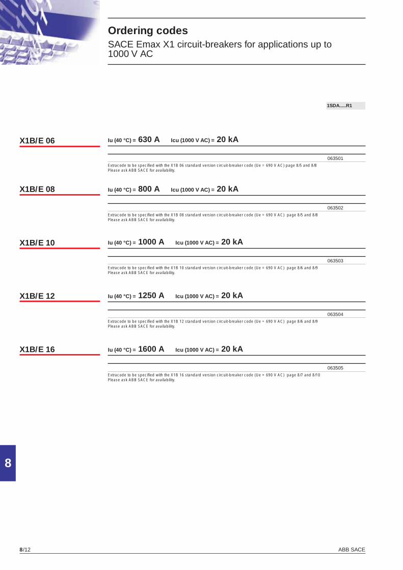
ABB SACE8/12
8
Ordering codes SACE Emax X1 circuit-breakers for applications up to 1000 V AC
1SDA.....R1
X1B/E 06
X1B/E 08
X1B/E 10
X1B/E 12
X1B/E 16
Iu (40 °C) = 630 A Icu (1000 V AC) = 20 kA
063501Extracode to be specifi ed with the X1B 06 standard version circuit-breaker code (Ue = 690 V AC) page 8/5 and 8/8 Please ask ABB SACE for availability.
Iu (40 °C) = 800 A Icu (1000 V AC) = 20 kA
063502Extracode to be specifi ed with the X1B 08 standard version circuit-breaker code (Ue = 690 V AC) page 8/5 and 8/8Please ask ABB SACE for availability.
Iu (40 °C) = 1000 A Icu (1000 V AC) = 20 kA
063503Extracode to be specifi ed with the X1B 10 standard version circuit-breaker code (Ue = 690 V AC) page 8/6 and 8/9 Please ask ABB SACE for availability.
Iu (40 °C) = 1250 A Icu (1000 V AC) = 20 kA
063504Extracode to be specifi ed with the X1B 12 standard version circuit-breaker code (Ue = 690 V AC) page 8/6 and 8/9 Please ask ABB SACE for availability.
Iu (40 °C) = 1600 A Icu (1000 V AC) = 20 kA
063505Extracode to be specifi ed with the X1B 16 standard version circuit-breaker code (Ue = 690 V AC) page 8/7 and 8/10 Please ask ABB SACE for availability.
X1_cap_8_02_14.indd 12X1_cap_8_02_14.indd 12 4-04-2007 10:02:084-04-2007 10:02:08
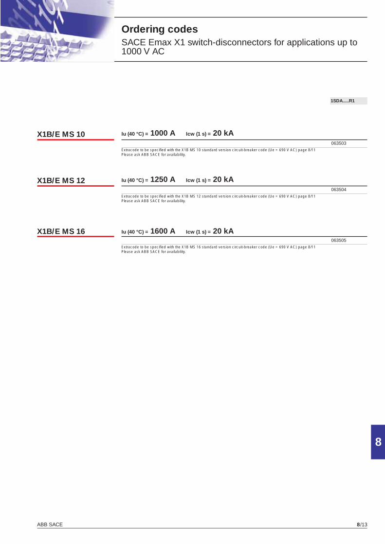
ABB SACE 8/13
8
Ordering codes SACE Emax X1 switch-disconnectors for applications up to 1000 V AC
1SDA.....R1
X1B/E MS 10
X1B/E MS 12
X1B/E MS 16
Iu (40 °C) = 1000 A Icw (1 s) = 20 kA 063503Extracode to be specifi ed with the X1B MS 10 standard version circuit-breaker code (Ue = 690 V AC) page 8/11 Please ask ABB SACE for availability.
Iu (40 °C) = 1250 A Icw (1 s) = 20 kA 063504Extracode to be specifi ed with the X1B MS 12 standard version circuit-breaker code (Ue = 690 V AC) page 8/11 Please ask ABB SACE for availability.
Iu (40 °C) = 1600 A Icw (1 s) = 20 kA 063505Extracode to be specifi ed with the X1B MS 16 standard version circuit-breaker code (Ue = 690 V AC) page 8/11 Please ask ABB SACE for availability.
X1_cap_8_02_14.indd 13X1_cap_8_02_14.indd 13 4-04-2007 10:02:094-04-2007 10:02:09
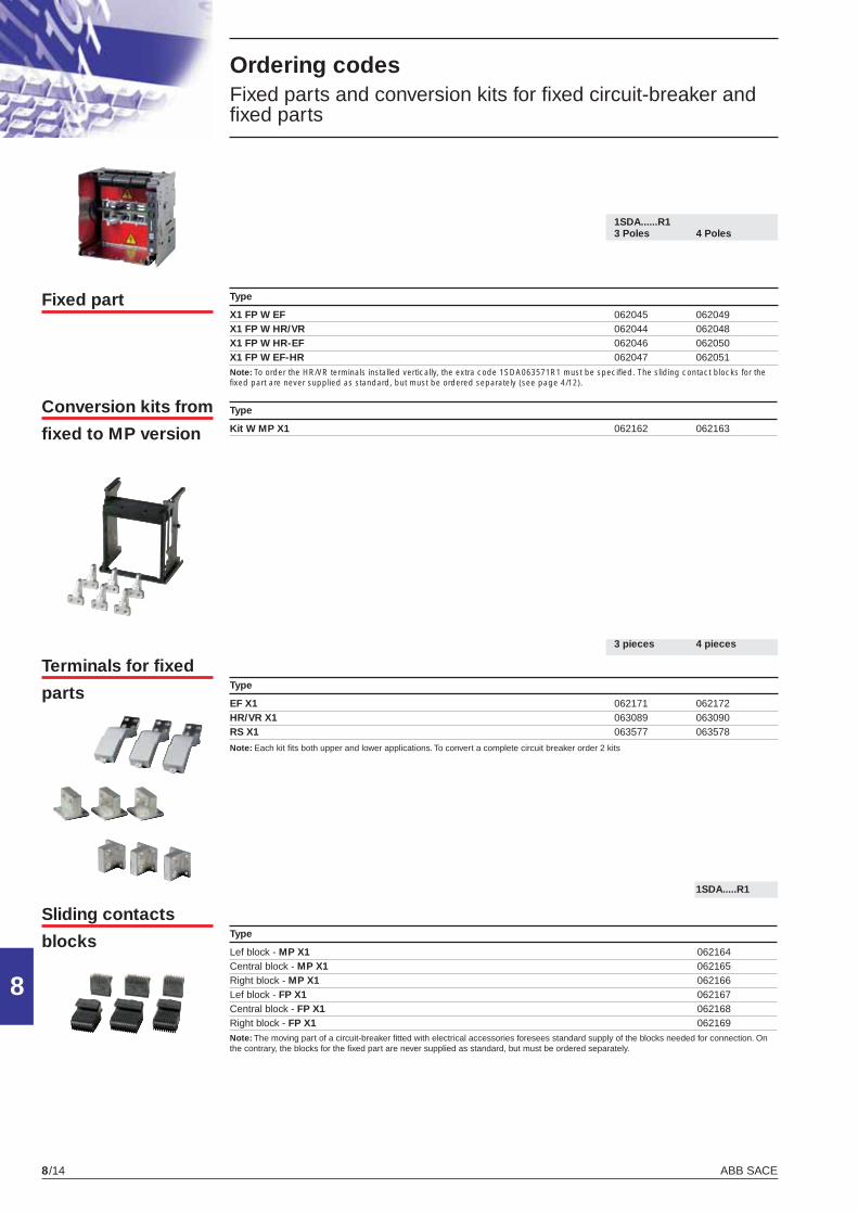
ABB SACE8/14
8
1SDA.....R1
Conversion kits from
fi xed to MP version
Ordering codes Fixed parts and conversion kits for fi xed circuit-breaker and fi xed parts
Fixed part Type
X1 FP W EF 062045 062049 X1 FP W HR/VR 062044 062048X1 FP W HR-EF 062046 062050 X1 FP W EF-HR 062047 062051 Note: To order the HR/VR terminals installed vertically, the extra code 1SDA063571R1 must be specifi ed. The sliding contact blocks for the fi xed part are never supplied as standard, but must be ordered separately (see page 4/12).
Type
EF X1 062171 062172 HR/VR X1 063089 063090RS X1 063577 063578
Note: Each kit fi ts both upper and lower applications. To convert a complete circuit breaker order 2 kits
Terminals for fi xed
parts
Sliding contacts
blocks
1SDA......R1 3 Poles 4 Poles
3 pieces 4 pieces
Type
Kit W MP X1 062162 062163
Type
Lef block - MP X1 062164 Central block - MP X1 062165 Right block - MP X1 062166 Lef block - FP X1 062167 Central block - FP X1 062168 Right block - FP X1 062169Note: The moving part of a circuit-breaker fi tted with electrical accessories foresees standard supply of the blocks needed for connection. On the contrary, the blocks for the fi xed part are never supplied as standard, but must be ordered separately.
X1_cap_8_02_14.indd 14X1_cap_8_02_14.indd 14 4-04-2007 10:02:094-04-2007 10:02:09
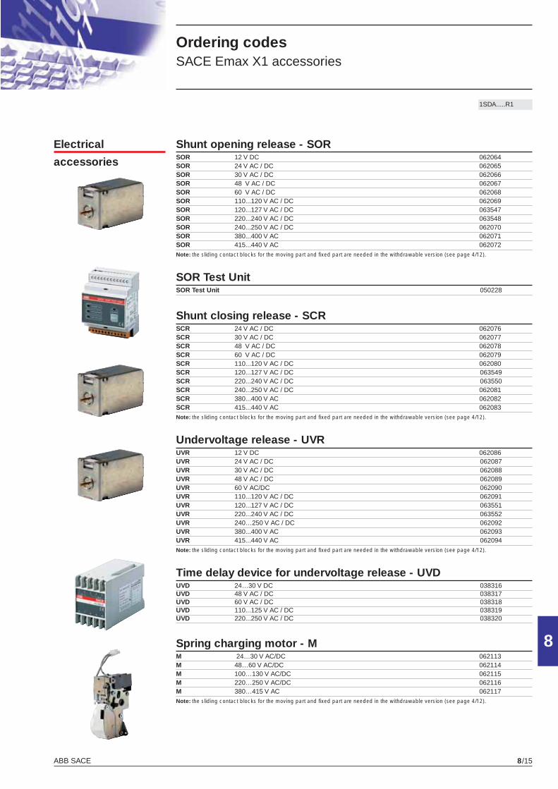
ABB SACE 8/15
8
Electrical
accessories
1SDA.....R1
Shunt opening release - SORSOR 12 V DC 062064 SOR 24 V AC / DC 062065 SOR 30 V AC / DC 062066 SOR 48 V AC / DC 062067 SOR 60 V AC / DC 062068 SOR 110...120 V AC / DC 062069 SOR 120...127 V AC / DC 063547 SOR 220...240 V AC / DC 063548 SOR 240...250 V AC / DC 062070 SOR 380...400 V AC 062071 SOR 415...440 V AC 062072 Note: the sliding contact blocks for the moving part and fi xed part are needed in the withdrawable version (see page 4/12).
SOR Test UnitSOR Test Unit 050228
Shunt closing release - SCR SCR 24 V AC / DC 062076 SCR 30 V AC / DC 062077 SCR 48 V AC / DC 062078 SCR 60 V AC / DC 062079 SCR 110...120 V AC / DC 062080 SCR 120...127 V AC / DC 063549 SCR 220...240 V AC / DC 063550 SCR 240...250 V AC / DC 062081 SCR 380...400 V AC 062082 SCR 415...440 V AC 062083 Note: the sliding contact blocks for the moving part and fi xed part are needed in the withdrawable version (see page 4/12).
Undervoltage release - UVR UVR 12 V DC 062086 UVR 24 V AC / DC 062087 UVR 30 V AC / DC 062088 UVR 48 V AC / DC 062089UVR 60 V AC/DC 062090UVR 110...120 V AC / DC 062091UVR 120...127 V AC / DC 063551 UVR 220...240 V AC / DC 063552 UVR 240…250 V AC / DC 062092UVR 380...400 V AC 062093UVR 415...440 V AC 062094Note: the sliding contact blocks for the moving part and fi xed part are needed in the withdrawable version (see page 4/12).
Time delay device for undervoltage release - UVD UVD 24…30 V DC 038316UVD 48 V AC / DC 038317UVD 60 V AC / DC 038318UVD 110...125 V AC / DC 038319UVD 220...250 V AC / DC 038320
Spring charging motor - M M 24…30 V AC/DC 062113M 48…60 V AC/DC 062114M 100…130 V AC/DC 062115M 220…250 V AC/DC 062116M 380…415 V AC 062117Note: the sliding contact blocks for the moving part and fi xed part are needed in the withdrawable version (see page 4/12).
Ordering codes SACE Emax X1 accessories
X1_cap_8_15_21.indd 15X1_cap_8_15_21.indd 15 4-04-2007 10:02:514-04-2007 10:02:51

ABB SACE8/16
8
1SDA.....R1
Trip reset Trip reset 24-30V AC/DC 063554Trip reset 110-130V AC/DC 062118Trip reset 200-240V AC/DC 062119Note: the sliding contact blocks for the moving part and fi xed part are needed in the withdrawable version (see page 4/12)
Auxiliary contacts - AUX auxiliary contacts (open/close) AUX 2Q 24 V DC 062101 AUX 2Q 400 V AC (1) 062102electrical signalling of electronic trip unit tripped AUX-SA 250V AC 063553auxiliary contact circuit breaker ready to close (2) AUX-RTC 24V DC 062108 AUX-RTC 250V AC/DC 062109auxiliary contact signalling spring charged AUX-SC 24V DC 062106 AUX-SC 250V AC/DC 062107(1) always supplied with automatic circuit-breakers; to be ordered separately with the switch-disconnector (2) in the withdrawable version where the sliding contact blocks for the moving and fi xed part are necessary (see page 4/12)
Auxiliary position contacts - AUP AUP X1 24V DC 062110AUP X1 250V AC 062111
Ordering codes SACE Emax X1 accessories
X1_cap_8_15_21.indd 16X1_cap_8_15_21.indd 16 4-04-2007 10:02:584-04-2007 10:02:58
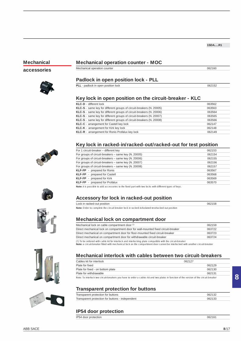
ABB SACE 8/17
8
1SDA.....R1
Mechanical operation counter - MOCMechanical operation counter 062160
Padlock in open position lock - PLL PLL - padlock in open position lock 062152
Key lock in open position on the circuit-breaker - KLCKLC-D - different lock 063562KLC-S - same key for different groups of circuit-breakers (N. 20005) 063563KLC-S - same key for different groups of circuit-breakers (N. 20006) 063564KLC-S - same key for different groups of circuit-breakers (N. 20007) 063565KLC-S - same key for different groups of circuit-breakers (N. 20008) 063566KLC-C - arrangement for Castell key lock 062147KLC-K - arrangement for Kirk key lock 062148KLC-R - arrangement for Ronis Profalux key lock 062149
Key lock in racked-in/racked-out/racked-out for test positionFor 1 circuit-breaker – different key 062153For groups of circuit-breakers – same key (N. 20005) 062154For groups of circuit-breakers – same key (N. 20006) 062155For groups of circuit-breakers – same key (N. 20007) 062156For groups of circuit-breakers – same key (N. 20008) 062157KLF-FP - prepared for Ronis 063567KLF-FP - prepared for Castell 063568KLF-FP - prepared for Kirk 063569KLF-FP - prepared for Profalux 063570Note: it is possible to add accessories to the fi xed part with two locks with different types of keys.
Accessory for lock in racked-out positionLock in racked-out position 062158Note: Order to complete the circuit breaker lock in racked-in/isolated-test/racked-out position
Mechanical lock on compartment doorMechanical lock on cable compartment door (1) 062159Direct mechanical lock on compartment door for wall-mounted fi xed circuit-breaker 063722Direct mechanical on compartment door for fl oor-mounted fi xed circuit-breaker 063723Direct mechanical on compartment door for withdrawable circuit-breaker 063724(1) To be ordered with cable kit for interlock and interlocking plate compatible with the circuit-breakerNote: a circuit-breaker fi tted with mechanical lock on the compartment door cannot be interlocked with another circuit-breaker
Mechanical interlock with cables between two circuit-breakersCables kit for interlock 062127Plate for fi xed 062129Plate for fi xed - on bottom plate 062130Plate for withdrawable 062131Note: To interlock two circuit-breakers you have to order a cables kit and two plates in function of the version of the circuit breaker
Transparent protection for buttons Transparent protection for buttons 062132Transparent protection for buttons - independent 062133
IP54 door protectionIP54 door protection 062161
Mechanical
accessories
X1_cap_8_15_21.indd 17X1_cap_8_15_21.indd 17 4-04-2007 10:03:044-04-2007 10:03:04
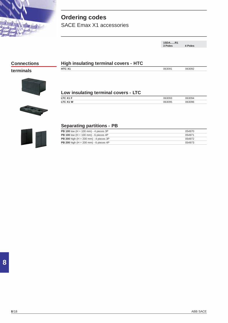
ABB SACE8/18
8
1SDA......R1 3 Poles 4 Poles
High insulating terminal covers - HTCHTC X1 063091 063092
Low insulating terminal covers - LTCLTC X1 F 063093 063094LTC X1 W 063095 063096
Separating partitions - PBPB 100 low (H = 100 mm) - 4 pieces 3P 054970PB 100 low (H = 100 mm) - 6 pieces 4P 054971PB 200 high (H = 200 mm) - 4 pieces 3P 054972PB 200 high (H = 200 mm) - 6 pieces 4P 054973
Connections
terminals
Ordering codes SACE Emax X1 accessories
X1_cap_8_15_21.indd 18X1_cap_8_15_21.indd 18 4-04-2007 10:03:134-04-2007 10:03:13
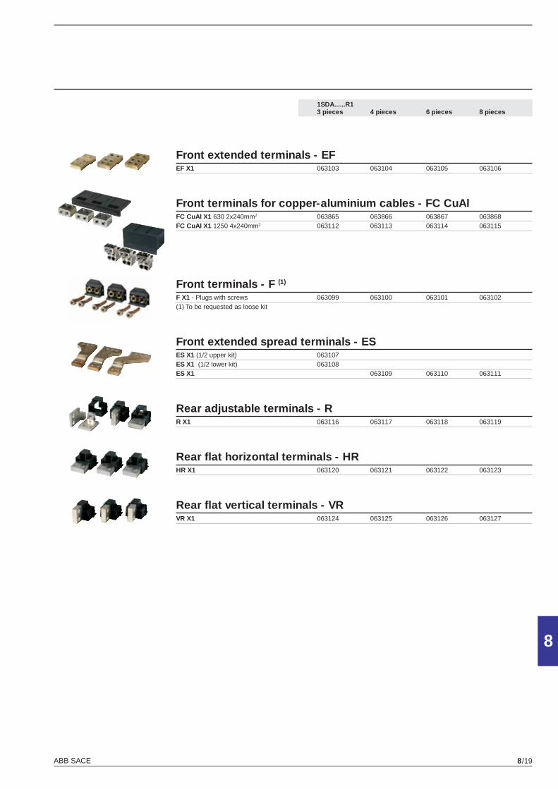
ABB SACE 8/19
8
1SDA......R1 3 pieces 4 pieces 6 pieces 8 pieces
Front extended terminals - EFEF X1 063103 063104 063105 063106
Front terminals for copper-aluminium cables - FC CuAlFC CuAl X1 630 2x240mm2 063865 063866 063867 063868 FC CuAl X1 1250 4x240mm2 063112 063113 063114 063115
Front terminals - F (1)
F X1 - Plugs with screws 063099 063100 063101 063102(1) To be requested as loose kit
Front extended spread terminals - ESES X1 (1/2 upper kit) 063107ES X1 (1/2 lower kit) 063108ES X1 063109 063110 063111
Rear adjustable terminals - RR X1 063116 063117 063118 063119
Rear fl at horizontal terminals - HRHR X1 063120 063121 063122 063123
Rear fl at vertical terminals - VRVR X1 063124 063125 063126 063127
X1_cap_8_15_21.indd 19X1_cap_8_15_21.indd 19 6-04-2007 9:13:076-04-2007 9:13:07
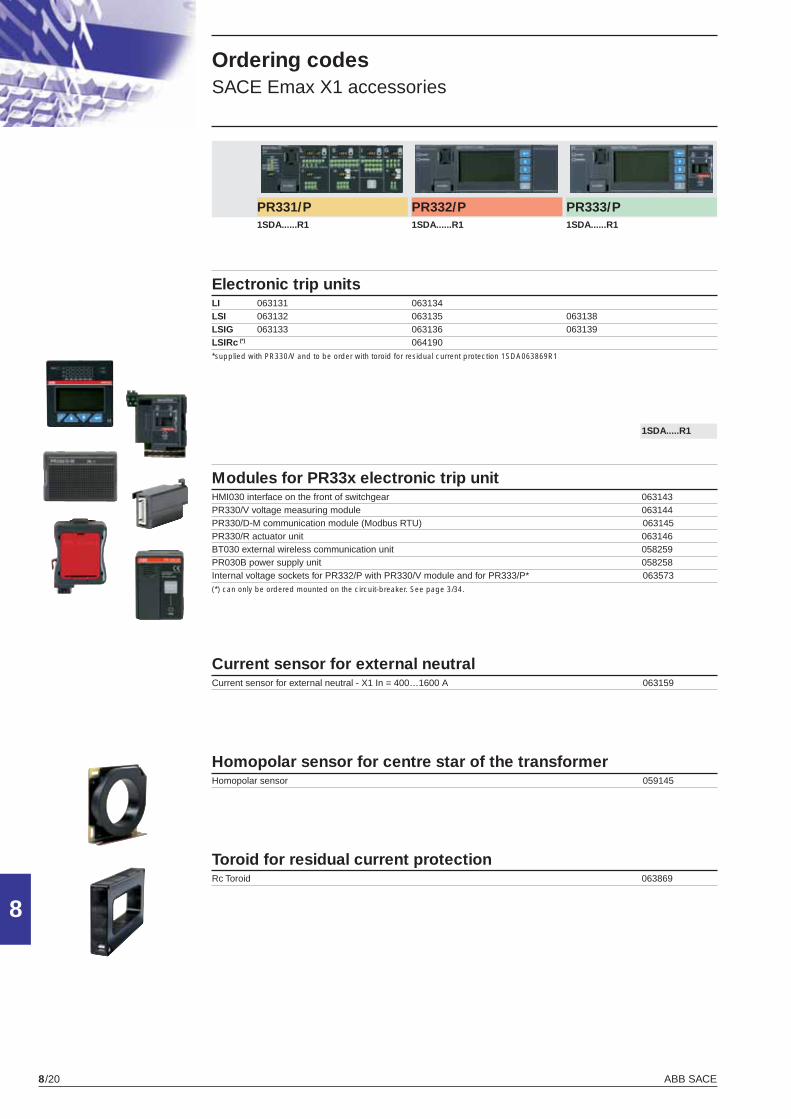
ABB SACE8/20
8
PR331/P PR332/P PR333/P 1SDA......R1 1SDA......R1 1SDA......R1
Electronic trip unitsLI 063131 063134LSI 063132 063135 063138LSIG 063133 063136 063139LSIRc (*) 064190*supplied with PR330/V and to be order with toroid for residual current protection 1SDA063869R1
1SDA.....R1
Modules for PR33x electronic trip unitHMI030 interface on the front of switchgear 063143PR330/V voltage measuring module 063144PR330/D-M communication module (Modbus RTU) 063145PR330/R actuator unit 063146BT030 external wireless communication unit 058259PR030B power supply unit 058258Internal voltage sockets for PR332/P with PR330/V module and for PR333/P* 063573(*) can only be ordered mounted on the circuit-breaker. See page 3/34.
Current sensor for external neutralCurrent sensor for external neutral - X1 In = 400…1600 A 063159
Homopolar sensor for centre star of the transformerHomopolar sensor 059145
Toroid for residual current protectionRc Toroid 063869
Ordering codes SACE Emax X1 accessories
X1_cap_8_15_21.indd 20X1_cap_8_15_21.indd 20 6-04-2007 9:13:096-04-2007 9:13:09
ABB SACE 8/21
8
Rating plug
1SDA.....R1
In=400A 063147In=630A 063148In=800A 063149In=1000A 063150In=1250A 063151In=1600A 063152In=400A for Rc protection (*) 063725In=630A for Rc protection (*)\ 063726In=800A for Rc protection (*) 063727In=1000A for Rc protection (*) 063728In=1250A for Rc protection (*) 063731In=1600A for Rc protection (*) 063732(*) for PR332/P LSIRc, PR332/P LSIG with PR330/V or PR333/P LSIG and toroid for residual current protection (see page 4/10)
Extracode
rating plug
Accessories for
electronic trip unitsPR010/T - Test and confi guration unit for electronic trip units type PR33x 048964 (1)
EP010 - Module interface for PR33x 059469 (1)
PR021/K - Signalling unit 059146 (1) ask ABB SACE for PR010/T and EP010 availability
Spare parts
Auxiliary units
In=400A 063153In=630A 063154In=800A 063155In=1000A 063156In=1250A 063157In=400A for Rc protection (*) 063733In=630A for Rc protection (*) 063734In=800A for Rc protection (*) 063735In=1000A for Rc protection (*) 063736In=1250A for Rc protection (*) 063737In=1600A for Rc protection (*) 064228(*) for PR332/P LSIRc or PR332/P LSIG and toroid for residual current protection (see page 4/11)
Software
Flanges for compartment doorFlange for compartment door for X1 fi xed 063160Flange for compartment door for X1 withdrawable 063161
Single terminalSingle terminal for X1 062170
Adapter of the PR33x protection unitAdapter for PR33x 063142Note: it is always supplied with the circuit-breaker
Automatic transfer switch ATS010ATS010 for X1 052927
SD-VIEW 2000 SoftwareSD-VIEW 2000 Software 060549SD-VIEW 2000 Software - 5000 Tags License 060550SD-VIEW 2000 Software - 10000 Tags License 060551SD-VIEW 2000 Software - 20000 Tags License 064106
X1_cap_8_15_21.indd 21X1_cap_8_15_21.indd 21 6-04-2007 9:13:276-04-2007 9:13:27

Technical catalogue X1 by Emax
Low voltage air circuit-breakers
1SDC200009D0202
X1
by
Em
ax
Lo
w v
olta
ge a
ir ci
rcui
t-br
eake
rs
Due to possible developments of standards as well as of materials, the characteristics and dimensions specified in the present catalogue may only be considered binding after confi rmation by ABB SACE. 1S
DC
2000
09D
0202
- 03
/200
7P
rinte
d in
Ital
y10
.000
- C
AL
ABB SACE S.p.A.An ABB Group company
L.V. BreakersVia Baioni, 3524123 Bergamo - ItalyTel.: +39 035.395.111 - Telefax: +39 035.395.306-433
http://www.abb.com
X1_copertina_new.indd 1X1_copertina_new.indd 1 6-04-2007 8:38:536-04-2007 8:38:53