taris 290-309 us - farnell element14 · taris concept taris with the wkc product range, wieland...
TRANSCRIPT

IDC connection for:• Standard DIN rail terminal blocks• Duo DIN rail terminal blocks• Multi-tier blocks• Disconnect blocks• Fuse blocks• Hybride terminal blocks
taris connects copper wires easily, fast and safely
taris for TS 35
no wire stripping, no ferrules
no special tools – a screwdriver is all you need
60 % time savings = reduced costs
low packing density (5 mm wide)
optical control of the switching state
cross sections up to 1.0 mm2 and 2.5 mm2
All Wieland Components which require A general certification are A certified, and identified with the A logo.
Technical information• The information regarding cross sectional area and connection
types pertains to unprepared wires without ferrules.• The voltage ratings apply to the terminals in their intended
application. When different products are mounted adjacent toeach other, the proper isolation distances must be adhered to.
• If the ground blocks of the taris product family are not used inblock assemblies, but are mounted to the rail as single terminalblocks, end clamps have to be used.
• A detailed description of technical data, the standards requirements, and the application conditions are available under facts & DATA.
ATEX regulation• For the use of DIN rail terminal blocks in Ex areas, the regulations
of EN 50014 apply; whereas for increased safety EExe theregulations of EN 50019 must be followed. For an approximationof the laws of the EU member states, directive 94/9/EG wascreated, which is generally known as ATEX 100a and which is the basis for harmonization in this field. ATEX stands for”atmosphere explosive” while 100a refers to the correspondingarticle of the EC contract.
• Directive ATEX 100a applies for protection against dust and gasexplosions in all industrial Ex areas and in mining.
• The testing and certificating institutes named in directive ATEX100a must follow accreditation procedures which are the sameall over Europe.
• In accordance with EN 50014/50019 and ATEX 100a, thesecertificating institutes write out EC certificates for prototypetests. These prototype test certificates for components together withthe corresponding quality system certification of the supplier arerequired to obtain the so-called ATEX approval.
• In combination with theOmark, the markings of the Wielandterminal blocks have the following meaning:
O IdentificationII Device group2 CategoryG D AreasKEMA Name of testing institute
ATEX... Certifcate, year of testing, number
Mounting instructions for EEx e applications• If feed-through blocks are mounted directly adjacent to
feed-through blocks of a different size, or directly adjacent toground blocks, the open side of a group of the same type ofblocks has to be covered by a partition.
• If adjacent terminal blocks are jumpered by a cross connector,the required isolation distances have to be maintained byinserting a partition between the different block groups, in frontof or behind the cross-connected terminal block group.
• If the terminal blocks are mixed with other certified series andsizes and if their accessories are used, the required creepagedistances and clearances must be adhered to.
• The DIN rail terminal blocks must be installed in a housing that meets the requirements of an approved protection typeaccording to EN 50 014 sec.1.2 or EN 50 289-1. The housingsmust have protection degree IP54 or higher depending on theprotection type selected.
DQS certification
for all company sectors• Quality standard as per DIN ISO 9001
in Development, Production and Assembly• Continued control of the quality standard by means of regular
internal and external quality audits• Compatible with certificates of other countries:
– BSI Certificate, Great Britain– SQS Certificate, Switzerland– Aib-Vincotte Certificate, Belgium– ÖQS Certificate, Austria

IDC Connectiontaris
DIN Rail Terminal Blocks
291

292
taristarisIDC DIN rail terminal blocks, type WKC

293Subject to change without further notice
Marking tagsMarking tag carrier
tarisIDC DIN rail terminal blocks, type WKC
WKC 2,5/35 WKC 1 SL/35 WKC 2,5 SL/35WKC 1/35
WKC 2,5 D1/2/35 WKC 1 D1/2/SL/35WKC 1 D1/2/35 WKN 150
WKC 1 D2/2/35 WKC 2,5 D2/2/35 WKC 1 D2/2/SL/35 WKC 2,5 D2/2/SL/35
WKC 1 E/35 WKC 2,5 E/35 WK 6 SL WKC 2,5 E/35...
WKC 1 TKM/35 WKC 2,5 TKM/35
WKC 1 TKG/35withTHSI 5x20
WKC 2,5 TKG/35 withTHSI 5x20
WKC 1 TKG/35 withTHSI 6,3x32
WKC 2,5 TKG/35 withTHSI 6,3x32
WKC 1 TKG/35 with SIST WKC 2,5 TKG/35 with SIST WKC 1 TKG/35 with DISR WKC 2,5 TKG/35 with DIST
WKF 16/35 PV/WKC
WKC 1 D2F/2C/SL/35
PS WKC/F
Page 300/301
Page 302/303
Page 304/305
Page 306/307
Page 308/309
Page 310/311
Page 312/313
Page 314/315
Page 318/319
Page 322/323
Page 324/325
Page 326/327
WKC 1 S/C/SL/35WKC 2,5 S/C/35WKC 1 S/C/35 WKC 2,5 S/C/SL/35
WKC 1 E/F/C/35WKC 1 D2F/2C/35WKC 2,5 F/C/SL/35WKC 2,5 F/C/35
WKC 2,5 D1/2/SL/35
TS 35x7,5 TS 35x15 TS 35x15 End clamp TS 35End clamp for TS 35
1 mm2/5 mm spacing 2,5 mm2/6 mm spacing

294 Subject to change without further notice
taristarisIDC DIN rail terminal blocks, type WKC
taris technology
The wire is cut to length and inserted into the wire entry guide until it reaches thedefined stopping point.
The clamping body is moved with a lever action of a standard screwdriver and piercesthe insulation of the conductor.
The spring-operated clamping body establishes the contact between the copperconductor and the busbar.
taris connects copper conductors simply, quickly and safely.
taris provides...
IDC connection technology
Simple operation of the terminationpoints
Reduced wiring time
Reduced panel space requirements
Controlled switching state
Complete product range
taris is designed for long-term useunder demanding conditions
Your benefits...
No stripping of insulationIt is not necessary to strip the insulationor attach ferrules for taris.
No special toolsOperation of the termination point witha standard screwdriver.
Cost reductionUp to 60 % time savings depending onthe type of conductor and connectiontechnology.
More space in the control cabinetOnly 5 mm width for WKC 1...
Circuit indicatorVisual indication of the termination pointposition, open or closed
Two cross section ranges
WKC 1... 0.2-1.0 mm2 / red*WKC 2,5... 1.0-2.5 mm2 / blue*
* Color of indicator
Terminal block variations
Standard terminal blocksFeed-through and ground blocks
Duo terminal blocksFeed-through and ground blocks
Multi-tier blocksFeed-through and function blocks
Disconnect blocksGround disconnect and knife edgedisconnect block
Safe connection– in accordance with EN 60352-3/4– in accordance with EN 60947-7-1/2means for example:
Multiple clampings Vibration resistance Use under corrosive conditions Climatic resistance
5mm
0.2........2.5mm2
10 20 30 40 50 60 70 80 90 100 %
taris
60%wiringwith
time saving
traditional wiring
time

295Subject to change without further notice
Our wieplan software helps to plan yourDIN rail terminal block assemblies(see page 36/37).
tarisIDC DIN rail terminal blocks, type WKC
Note
The information regarding cross-sectionalareas and connection types pertains towires without ferrules. Ferrules are notneccessary for secure connection.
The voltage ratings apply to the terminals in their intended application.When different products are mountedadjacent to each other, the properisolation distances must be adhered to.For this purpose, Wieland offers a largeselection of appropiate accessories.
A detailed description of technical data,the standards requirements, and theapplication conditions can be found incatalog section facts & DATA.
Materials
Metal parts:
Special alloys enable low feed-throughresistance and provide a gas-tightcontact area:
Clamping body: tin-plated copper
Busbar: tin-plated copper
Mounting foot: tin-plated brass
Insulating material:
Polyamide has excellent electrical, chemical and mechanical characteristics.
Insulating housings: Polyamide 66/6
Creepage resistance: CTI 600
Flammability class: UL 94-V0
(also see section facts & DATA)
DQS certificates for all products
Quality standard as per DIN ISO 9001 In Development, Production, Assembly Continued control of the quality standard
by means of regular internal and externalquality audits
Compatible with certificates of othercountries:
– BSI Certificate, Great Britain– SQS Certificate, Switzerland– Aib-Vincotte Certificate, Belgium– ÖQS Certificate, Austria
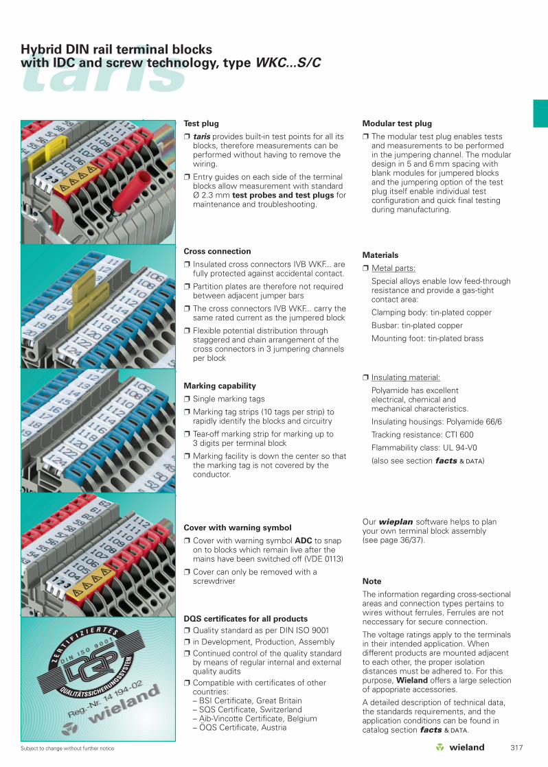
Marking accessories
Single marking tag
Marking strips (10 single tags) for snappingonto the terminal strip.
Tear-off marking strips for 3-digit markingper block
Custom marking available on request
ADC warning cover
taris offers a snap-on cover with the ADCwarning symbol to prevent tampering ofblocks which remain live after the systemis switched off.
A tool is required to remove the cover foradded safety.
Cross connection
IVB WKF insulated cross connectors offercomplete protection from shock-hazardper EN 60352-3/4 and EN 60947-7-1.
Partition plates between neighboring crossconnections are not necessary to meetcreepage requirements.
IVB WKF cross connectors bear the samerated current as the terminal block
Test plug
taris provides built-in test points for all itsblocks, therefore measurements can beperformed without having to remove thewiring.
Entry guides on each side of the terminalblocks allow measurement with standardØ 2.3 mm test probes and test plugs formaintenance and troubleshooting.
Modular test plug
The modular test plug enables testsand measurements to be performedin the jumpering channel. The modulardesign in 5 and 6 mm spacing withblank modules for jumpered blocksand the jumpering option of the testplug itself enable individual testconfigurations and quick final testingduring manufacturing.

296 Subject to change without further notice
taristarisConcept
taris
With the WKC product range, Wieland completes its range of DIN railterminal blocks and provides the appropriate connection technologyfor any control cabinet application.
The WKC series enables the connection of copper wires usingInsulation Displacement Connection.
Our DIN rail terminal blocks with IDC connection are called taris.
taris reduces your wiring costs and provides all the benefits of ourscrew and spring clamp terminal blocks.
The circuit
Wiring of copper conductors with taris is simple, quick and safe.
• Simple – The wire is ONLY cut to length, inserted into the clampingbody and the termination point is operated with a standardscrewdriver in a lever action-done.
• Quick – Time-consuming tasks for preparing the wires such asstripping the insulation and attaching ferrules are notrequired. Time savings of up to 60% lead to cost reduction.
• Safe – The conductor is not moved during operation – as with allother Wieland terminal blocks. Therefore, there is no risk ofthe conductors sliding out of position with taris.
The position indicator visually indicates the state of thetermination point. The color of the indicator signifies the rated cross sectionof the DIN rail terminal block.
WKC 1... 0.21 – 1.0 mm2 red indicatorWKC 2,5... 1.0 – 2.5 mm2 blue indicator
Repeated operation of the released wires is of coursepossible with taris. Smaller cross sections replace previously connected larger wire sizes without technicaldifficulties.
It is just as simple, quick and safe to disconnect the conductor withtaris as it is to connect it.
Wire specifications
taris terminates solid or fine-stranded copper wires with AWG between24 and 14 with two size of terminal blocks.
WKC ...1 : copper wire between AWG 24-18; 5 mm wide terminal blockWKC ...2,5: copper wire between AWG 18-14; 6 mm wide terminal block
Standard control wire with PVC- and PE- insulation can be terminated
Wire with other insulation material can also be terminated, please consultWieland for recommendation
For fine-stranded copper wires, the wire diameter must be a minimum of0.2 mm. The composition of conductors is based on DIN VDE 0295 K1.1-5.
Termination point ”open”
WK
F 1
.5...1
6 m
m2
WK
C 1
.0-2
.5 m
m2
WK
N 2
.5...1
50 m
m2
Termination point ”closed”

297Subject to change without further notice
tarisConcept
The connection
The wire is inserted through the wire entry guide of the block into the clampingbody. By operating it with a standard screwdriver, the clamping body is movedand cuts the insulation of the inserted copper wire at a defined point.
The inserted wire does not move during this operation and therefore cannotslide out of the clamping body when the circuit is closed.
The clamping body is made of a copper alloy which provides a high-qualityconnection between the wire and the current carrying bar. The contact quality achieved exceeds the requirements stipulated in thestandards 60947-7-1 and 60352-3.
taris enables connection of rigid and flexible copper wires of a rated crosssection between 0.21 and 2.5 mm2 in two cross section ranges.
The accessories
• The standard Wieland marking system is used for taris.
• For potential distribution we use the insulated cross connectors from ourspring clamp connection technology.
• To implement certain connection requirements, the disconnect terminalblocks are used together with the SIST or THSI fuse plugs or the DIST diodeplug from the WK or WKF range.
• To segregate groups of terminal blocks visually, taris provides partitions andend plates with different outer contours in order to maintain protectionagainst accidental contact.
• For maintenance and troubleshooting, taris is equipped with test points fortest probes or test plugs.
The series
taris offers numerous terminal block variations in two wire ranges for mostdifferent applications. Both cross section ranges have the same outercontour:
Standard DIN rail terminal blocks
• Terminal blocks that act as feed-through and ground blocks with onetermination point on each side of the block.
• Terminal blocks with two jumpering channels provide flexibility in potentialdistribution.
• Terminal blocks with a marking facility for each termination point.• Terminal blocks with a test hole for test probes at each termination point.
Duo DIN rail terminal blocks
• Duo terminal blocks with more than two termination points for one potential.
• Duo terminal blocks as feed-through and ground blocks in D1/2 and D2/2designs.
• Duo terminal blocks D1/2 can be jumpered with standard DIN rail terminalblocks.
Disconnect terminal blocks
• Knife edge disconnect and disconnect blocks with diode or fuse plugs.• Disconnect blocks can be jumpered with standard duo 1/2 terminal blocks.
Multi-tier terminal blocks
• Multi-tier terminal blocks have the same contour as duo 2/2 terminal blocks.• Multi-tier terminal blocks as function blocks for diode switching.

taristarisIDC DIN rail terminal blocks, type WKC
298 Subject to change without further notice
23
4567
8
910
11121314
151617
18
19
2120
2524
23
22
1

WKC 1/35 56.301.0053.0
WKC 1/35 BLAU 56.301.0053.6
WKC 1 SL/35 56.301.9053.0
WKC 2,5/35 56.303.0053.0
WKC 2,5/35 BLAU 56.303.0053.6
WKC 2,5 SL/35 56.303.9053.0
WKC 1 D1/2/35 56.301.5053.0
WKC 2,5 D1/2/35 56.303.5053.0
WKC 2,5 TKG/35 56.303.4053.0
WKC 1 TKG/35 56.301.4053.0
WKC 2,5 TKM/35 56.303.2053.0
WKC 1 TKM/35 56.301.2053.0
WKC 1 D2/2/35 56.301.5153.0
WKC 1 E/35 56.301.7053.0
WKC 2,5 D2/2/SL/35 56.303.9153.0
WKC 2,5 D2/2/35 56.303.5153.0
WKC 2,5 E/35 56.303.7053.0
APC 1-2,5 D2./E. 07.312.5453.0
TWC 1-2,5 D2./E. 07.312.5553.0
ADC 2,5 GELB 04.344.0353.8
IVB WKF 4-2 Z7.261.1227.0
SIST Z1.299.4053.0
35x27x7,5 EN 60715 98.300.0000.0
9708/2 S35 Z5.522.8553.0
9705 A/5/10 B 04.842.5053.0
taristaris sample rail
299Subject to change without further notice
Pos. Description Type Part No.
1 Feed-through block
2 Feed-through block, blue
3 Ground block
4 Feed-through block
5 Feed-through block, blue
6 Ground block
7 Duo feed-through block
8 Duo feed-through block
9 Disconnect block
10 Disconnect block
11 Knife edge disconnect block
12 Knife edge disconnect block
13 Duo feed-through block
14 Double-tier block
15 Duo-ground block
16 Duo-feed-through block
17 Double-tier block
18 End plate
19 Partition plate
20 Cover with warning symbol
21 Jumper bar, insulated
22 Fuse plug (G 5x20)
23 Mounting rail
24 End clamp
25 Marking strips

300 Subject to change without further notice
taristarisIDC feed-through blocks, type WKC
WKC 1/35
fine-stranded solid V A0.2 – 1 mm2 0.2 – 1 mm2 800 V/8 kV/3 13,5No. 30-18 AWG 600 V 13No. 24-18 AWG 600 V 130.2 – 1 mm2 0.2 – 1 mm2 750 V 13,55 mm 1 mm2
uCqkwh
WKC 2,5/35
fine-stranded solid V A1 – 2.5 mm2 1 – 2.5 mm2 800 V/8 kV/3 24No. 18-14 AWG 600 V 22No. 16-14 AWG 600 V 201 – 2.5 mm2 1 – 2.5 mm2 750 V 246 mm 2.5 mm2
uCqkwh
0344OII 2GDEEx eIIEN 60 947-7-2/DIN VDE 0611 T1UL ratingsCSA ratingsKEMA 02 ATEX 2113 U1) EN 50019/EN 50014Width Rated cross sectionApprovals
Type Part No. Std. Pack Type Part No. Std. Pack
WKC 1/35 56.301.0053.0 100
WKC 1/35 BLAU 56.301.0053.6 100
35 x 27 x 7,5 EN 60715 98.300.0000.0 1
35 x 24 x 15 EN 60715 98.360.0000.0 1
9708/2 S 35 Z5.522.8553.0 100
WEF 1/35 Z5.523.9353.0 100
APC 1-2,5 07.312.5053.0 10
APC 1-2,5 BLAU 07.312.5053.6 10
TWC 1-2,5 07.312.5153.0 10
TWC 1-2,5 BLAU 07.312.5153.6 10
IVB WKF 2,5-2 Z7.280.6227.0 10
IVB WKF 2,5-3 Z7.280.6327.0 10
IVB WKF 2,5-4 Z7.280.6427.0 10
IVB WKF 2,5-5 Z7.280.6527.0 10
IVB WKF 2,5-6 Z7.280.6627.0 10
IVB WKF 2,5-7 Z7.280.6727.0 20
IVB WKF 2,5-8 Z7.280.6827.0 20
IVB WKF 2,5-9 Z7.280.6927.0 20
IVB WKF 2,5-10 Z7.280.7027.0 20
ADC 1 GELB 04.344.0153.8 10
WK 2,5 ST 2/2,3 Z5.553.2921.0 10
PS WKC/F Z1.299.9753.0 10
01.299.9753.0 10
ZP/AP PS 07.312.6053.0 10
DIN 5264 B 0,6 x 3,5 06.502.4000.0 5
WKC 2,5/35 56.303.0053.0 100
WKC 2,5/35 BLAU 56.303.0053.6 100
35 x 27 x 7,5 EN 60715 98.300.0000.0 1
35 x 24 x 15 EN 60715 98.360.0000.0 1
9708/2 S 35 Z5.522.8553.0 100
WEF 1/35 Z5.523.9353.0 100
APC 1-2,5 07.312.5053.0 10
APC 1-2,5 BLAU 07.312.5053.6 10
TWC 1-2,5 07.312.5153.0 10
TWC 1-2,5 BLAU 07.312.5153.6 10
IVB WKF 4-2 Z7.261.1227.0 10
IVB WKF 4-3 Z7.261.1327.0 10
IVB WKF 4-4 Z7.261.1427.0 10
IVB WKF 4-5 Z7.261.1527.0 10
IVB WKF 4-6 Z7.261.1627.0 10
IVB WKF 4-7 Z7.261.1727.0 20
IVB WKF 4-8 Z7.261.1827.0 20
IVB WKF 4-9 Z7.261.1927.0 20
IVB WKF 4-10 Z7.261.2027.0 20
ADC 2,5 GELB 04.344.0353.8 10
WK 2,5 ST 2/2,3 Z5.553.2921.0 10
PS WKC/F Z1.299.9753.0 10
01.299.9753.0 10
ZP/AP PS 07.312.6053.0 10
DIN 5264 B 0,6 x 3,5 06.502.4000.0 5
*) In order to maintain the proper isolation distances, the open side of a ground block is to be covered by an end plate.1) Please note the mounting instructions on page 290. 2) Do not use in Ex environments.
Feed-through block gray
Feed-through block blue
Accessories
1. Mounting rail 35, 7.5 mm high L = 2 m
Mounting rail 35, 15 mm high L = 2 m
2. End clamp for TS 352), with screw 8 mm wide
End clamp for TS 35, screwless 8 mm wide
3. End plate gray
blue
green
4. Partition plate gray
blue
5. Jumper bar, 2 pole
insulated 3 pole
4 pole
5 pole
6 pole
7 pole
8 pole
9 pole
10 pole
6. Cover w. warning symbol over 4 blocks
7. Test plug
8. Modular test plug with spring clamp connection
Blank module for jumpered blocks
End/intermediate plate for 6 mm spacing
9. Screw driver, uninsulated
Marking accessories also see page 326-327

301Subject to change without further notice
tarisIDC ground blocks, type WKC
WKC 1 SL/35
fine-stranded solid V A0.2 – 1 mm2 0.2 – 1 mm2 800 V/8 kV/3 13.5No. 30-18 AWG 600 VNo. 24-18 AWG0.2 – 1 mm2 0.2 – 1 mm2 *)
5 mm 1 mm2
uCqkwh
WKC 2,5 SL/35
fine-stranded solid V A1 – 2.5 mm2 1 – 2.5 mm2 800 V/8 kV/3 24No. 18-14 AWG 600 VNo. 16-14 AWG1 – 2.5 mm2 1 – 2.5 mm2 *)
6 mm 2.5 mm2
uCqkwh
0344OII 2GDEEx eIIEN 60 947-7-2/DIN VDE 0611 T1UL ratingsCSA ratingsKEMA 02 ATEX 2113 U1) EN 50019/EN 50014Width Rated cross sectionApprovals
Type Part No. Std. Pack Type Part No. Std. Pack
WKC 1 SL/35 56.301.9053.0 100
35 x 27 x 7,5 EN 60715 98.300.0000.0 1
35 x 24 x 15 EN 60715 98.360.0000.0 1
9708/2 S 35 Z5.522.8553.0 100
WEF 1/35 Z5.523.9353.0 100
APC 1-2,5 GRÜN 07.312.5053.7 10
ADC 1 GELB 04.344.0153.8 10
WK 2,5 ST 2/2,3 Z5.553.2921.0 10
PS WKC/F Z1.299.9753.0 10
01.299.9753.0 10
ZP/AP PS 07.312.6053.0 10
DIN 5264 B 0,6 x 3,5 06.502.4000.0 5
WKC 2,5 SL/35 56.303.9053.0 100
35 x 27 x 7,5 EN 60715 98.300.0000.0 1
35 x 24 x 15 EN 60715 98.360.0000.0 1
9708/2 S 35 Z5.522.8553.0 100
WEF 1/35 Z5.523.9353.0 100
APC 1-2,5 GRÜN 07.312.5053.7 10
ADC 2,5 GELB 04.344.0353.8 10
WK 2,5 ST 2/2,3 Z5.553.2921.0 10
PS WKC/F Z1.299.9753.0 10
01.299.9753.0 10
ZP/AP PS 07.312.6053.0 10
DIN 5264 B 0,6 x 3,5 06.502.4000.0 5
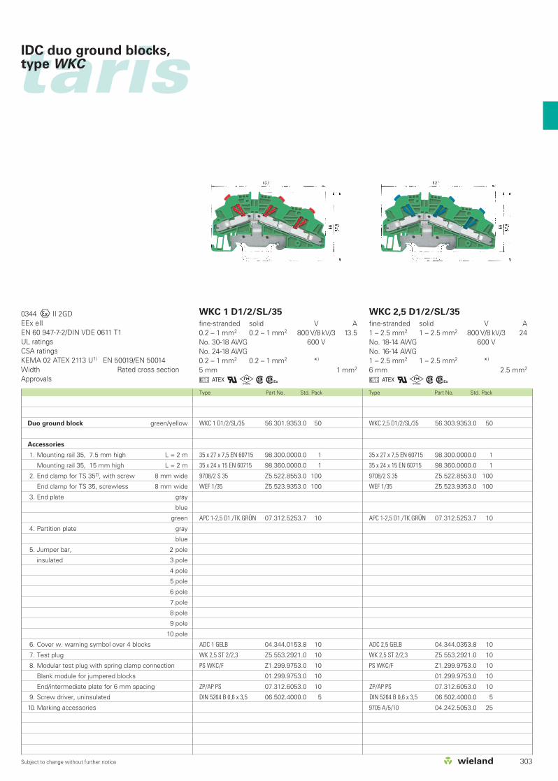
Ground block green/yellow
Accessories
1. Mounting rail 35, 7.5 mm high L = 2 m
Mounting rail 35, 15 mm high L = 2 m
2. End clamp for TS 352), with screw 8 mm wide
End clamp for TS 35, screwless 8 mm wide
3. End plate gray
blue
green
4. Partition plate gray
blue
5. Jumper bar, 2 pole
insulated 3 pole
4 pole
5 pole
6 pole
7 pole
8 pole
9 pole
10 pole
6. Cover w. warning symbol over 4 blocks
7. Test plug
8. Modular test plug with spring clamp connection
Blank module for jumpered blocks
End/intermediate plate for 6 mm spacing
9. Screw driver, uninsulated

302 Subject to change without further notice
taristarisIDC duo feed-through blocks, type WKC
WKC 1 D1/2/35
fine-stranded solid V A0.2 – 1 mm2 0.2 – 1 mm2 800 V/8 kV/3 13.5No. 30-18 AWG 600 V 13No. 24-18 AWG 600 V 130.2 – 1 mm2 0.2 – 1 mm2 750 V 13.55 mm 1 mm2
uCqkwh
WKC 2,5 D1/2/35
fine-stranded solid V A1 – 2.5 mm2 1 – 2.5 mm2 800 V/8 kV/3 24No. 18-14 AWG 600 V 22No. 16-14 AWG 600 V 201 – 2.5 mm2 1 – 2.5 mm2 750 V 246 mm 2.5 mm2
uCqkwh
0344OII 2GDEEx eIIEN 60 947-7-2/DIN VDE 0611 T1UL ratingsCSA ratingsKEMA 02 ATEX 2113 U1) EN 50019/EN 50014Width Rated cross sectionApprovals
Type Part No. Std. Pack Type Part No. Std. Pack
WKC 2,5 D1/2/35 56.303.5053.0 50
WKC 2,5 D1/2/35 BLAU 56.303.5053.6 50
35 x 27 x 7,5 EN 60715 98.300.0000.0 1
35 x 24 x 15 EN 60715 98.360.0000.0 1
9708/2 S 35 Z5.522.8553.0 100
WEF 1/35 Z5.523.9353.0 100
APC 1-2,5 D1./TK. 07.312.5253.0 10
APC 1-2,5 D1./TK.BLAU 07.312.5253.6 10
TWC 1-2,5 D1. 07.312.5353.0 10
TWC 1-2,5 D1. BLAU 07.312.5353.6 10
IVB WKF 4-2 Z7.261.1227.0 10
IVB WKF 4-3 Z7.261.1327.0 10
IVB WKF 4-4 Z7.261.1427.0 10
IVB WKF 4-5 Z7.261.1527.0 10
IVB WKF 4-6 Z7.261.1627.0 10
IVB WKF 4-7 Z7.261.1727.0 20
IVB WKF 4-8 Z7.261.1827.0 20
IVB WKF 4-9 Z7.261.1927.0 20
IVB WKF 4-10 Z7.261.2027.0 20
ADC 2,5 GELB 04.344.0353.8 10
WK 2,5 ST 2/2,3 Z5.553.2921.0 10
PS WKC/F Z1.299.9753.0 10
01.299.9753.0 10
ZP/AP PS 07.312.6053.0 10
DIN 5264 B 0,6 x 3,5 06.502.4000.0 5
9705 A/5/10 04.242.5053.0 25
*) In order to maintain the proper isolation distances, the open side of a ground block is to be covered by an end plate.1) Please note the mounting instructions on page 290. 2) Do not use in Ex environments.
WKC 1 D1/2/35 56.301.5053.0 50
WKC 1 D1/2/35 BLAU 56.301.5053.6 50
35 x 27 x 7,5 EN 60715 98.300.0000.0 1
35 x 24 x 15 EN 60715 98.360.0000.0 1
9708/2 S 35 Z5.522.8553.0 100
WEF 1/35 Z5.523.9353.0 100
APC 1-2,5 D1./TK. 07.312.5253.0 10
APC 1-2,5 D1./TK.BLAU 07.312.5253.6 10
TWC 1-2,5 D1. 07.312.5353.0 10
TWC 1-2,5 D1. BLAU 07.312.5353.6 10
IVB WKF 2,5-2 Z7.280.6227.0 10
IVB WKF 2,5-3 Z7.280.6327.0 10
IVB WKF 2,5-4 Z7.280.6427.0 10
IVB WKF 2,5-5 Z7.280.6527.0 10
IVB WKF 2,5-6 Z7.280.6627.0 10
IVB WKF 2,5-7 Z7.280.6727.0 20
IVB WKF 2,5-8 Z7.280.6827.0 20
IVB WKF 2,5-9 Z7.280.6927.0 20
IVB WKF 2,5-10 Z7.280.7027.0 20
ADC 1 GELB 04.344.0153.8 10
WK 2,5 ST 2/2,3 Z5.553.2921.0 10
PS WKC/F Z1.299.9753.0 10
01.299.9753.0 10
ZP/AP PS 07.312.6053.0 10
DIN 5264 B 0,6 x 3,5 06.502.4000.0 5
Duo feed-through block gray
Duo feed-through block blue
Accessories
1. Mounting rail 35, 7.5 mm high L = 2 m
Mounting rail 35, 15 mm high L = 2 m
2. End clamp for TS 352), with screw 8 mm wide
End clamp for TS 35, screwless 8 mm wide
3. End plate gray
blue
green
4. Partition plate gray
blue
5. Jumper bar, 2 pole
insulated 3 pole
4 pole
5 pole
6 pole
7 pole
8 pole
9 pole
10 pole
6. Cover w. warning symbol over 4 blocks
7. Test plug
8. Modular test plug with spring clamp connection
Blank module for jumpered blocks
End/intermediate plate for 6 mm spacing
9. Screw driver, uninsulated
10. Marking accessories
Marking accessories also see page 326-327
303Subject to change without further notice
tarisIDC duo ground blocks, type WKC
WKC 1 D1/2/SL/35
fine-stranded solid V A0.2 – 1 mm2 0.2 – 1 mm2 800 V/8 kV/3 13.5No. 30-18 AWG 600 VNo. 24-18 AWG0.2 – 1 mm2 0.2 – 1 mm2 *)
5 mm 1 mm2
uCqkwh
WKC 2,5 D1/2/SL/35
fine-stranded solid V A1 – 2.5 mm2 1 – 2.5 mm2 800 V/8 kV/3 24No. 18-14 AWG 600 VNo. 16-14 AWG1 – 2.5 mm2 1 – 2.5 mm2 *)
6 mm 2.5 mm2
uCqkwh
0344OII 2GDEEx eIIEN 60 947-7-2/DIN VDE 0611 T1UL ratingsCSA ratingsKEMA 02 ATEX 2113 U1) EN 50019/EN 50014Width Rated cross sectionApprovals
Type Part No. Std. Pack Type Part No. Std. Pack
WKC 2,5 D1/2/SL/35 56.303.9353.0 50
35 x 27 x 7,5 EN 60715 98.300.0000.0 1
35 x 24 x 15 EN 60715 98.360.0000.0 1
9708/2 S 35 Z5.522.8553.0 100
WEF 1/35 Z5.523.9353.0 100
APC 1-2,5 D1./TK.GRÜN 07.312.5253.7 10
ADC 2,5 GELB 04.344.0353.8 10
WK 2,5 ST 2/2,3 Z5.553.2921.0 10
PS WKC/F Z1.299.9753.0 10
01.299.9753.0 10
ZP/AP PS 07.312.6053.0 10
DIN 5264 B 0,6 x 3,5 06.502.4000.0 5
9705 A/5/10 04.242.5053.0 25
WKC 1 D1/2/SL/35 56.301.9353.0 50
35 x 27 x 7,5 EN 60715 98.300.0000.0 1
35 x 24 x 15 EN 60715 98.360.0000.0 1
9708/2 S 35 Z5.522.8553.0 100
WEF 1/35 Z5.523.9353.0 100
APC 1-2,5 D1./TK.GRÜN 07.312.5253.7 10
ADC 1 GELB 04.344.0153.8 10
WK 2,5 ST 2/2,3 Z5.553.2921.0 10
PS WKC/F Z1.299.9753.0 10
01.299.9753.0 10
ZP/AP PS 07.312.6053.0 10
DIN 5264 B 0,6 x 3,5 06.502.4000.0 5
Duo ground block green/yellow
Accessories
1. Mounting rail 35, 7.5 mm high L = 2 m
Mounting rail 35, 15 mm high L = 2 m
2. End clamp for TS 352), with screw 8 mm wide
End clamp for TS 35, screwless 8 mm wide
3. End plate gray
blue
green
4. Partition plate gray
blue
5. Jumper bar, 2 pole
insulated 3 pole
4 pole
5 pole
6 pole
7 pole
8 pole
9 pole
10 pole
6. Cover w. warning symbol over 4 blocks
7. Test plug
8. Modular test plug with spring clamp connection
Blank module for jumpered blocks
End/intermediate plate for 6 mm spacing
9. Screw driver, uninsulated
10. Marking accessories

304 Subject to change without further notice
taristarisIDC duo feed-through blocks, type WKC
WKC 1 D2/2/35
fine-stranded solid V A0.2 – 1 mm2 0.2 – 1 mm2 500 V/6 kV/3 13.5No. 30-18 AWG 600 V 13No. 24-18 AWG 300/600 V* 130.2 – 1 mm2 0.2 – 1 mm2 550 V 13.55 mm 1 mm2
uCqkwh
WKC 2,5 D2/2/35
fine-stranded solid V A1 – 2.5 mm2 1 – 2.5 mm2 500 V/6 kV/3 24No. 18-14 AWG 600 V 22No. 16-14 AWG 300/600 V 201 – 2.5 mm2 1 – 2.5 mm2 550 V 246 mm 2.5 mm2
uCqkwh
0344OII 2GDEEx eIIEN 60 947-7-2/DIN VDE 0611 T1UL ratingsCSA ratingsKEMA 02 ATEX 2113 U1) EN 50019/EN 50014Width Rated cross sectionApprovals
Type Part No. Std. Pack Type Part No. Std. Pack
WKC 2,5 D2/2/35 56.303.5153.0 50
WKC 2,5 D2/2/35 BLAU 56.303.5153.6 50
35 x 27 x 7,5 EN 60715 98.300.0000.0 1
35 x 24 x 15 EN 60715 98.360.0000.0 1
9708/2 S 35 Z5.522.8553.0 100
WEF 1/35 Z5.523.9353.0 100
APC 1-2,5 D2./E. 07.312.5453.0 10
APC 1-2,5 D2./E. BLAU 07.312.5453.6 10
TWC 1-2,5 D2./E. 07.312.5553.0 10
TWC 1-2,5 D2./E. BLAU 07.312.5553.6 10
IVB WKF 4-2 Z7.261.1227.0 10
IVB WKF 4-3 Z7.261.1327.0 10
IVB WKF 4-4 Z7.261.1427.0 10
IVB WKF 4-5 Z7.261.1527.0 10
IVB WKF 4-6 Z7.261.1627.0 10
IVB WKF 4-7 Z7.261.1727.0 20
IVB WKF 4-8 Z7.261.1827.0 20
IVB WKF 4-9 Z7.261.1927.0 20
IVB WKF 4-10 Z7.261.2027.0 20
ADC 2,5 GELB 04.344.0353.8 10
WK 2,5 ST 2/2,3 Z5.553.2921.0 10
PS WKC/F Z1.299.9753.0 10
01.299.9753.0 10
ZP/AP PS 07.312.6053.0 10
DIN 5264 B 0,6 x 3,5 06.502.4000.0 5
WKC 1 D2/2/35 56.301.5153.0 50
WKC 1 D2/2/35 BLAU 56.301.5153.6 50
35 x 27 x 7,5 EN 60715 98.300.0000.0 1
35 x 24 x 15 EN 60715 98.360.0000.0 1
9708/2 S 35 Z5.522.8553.0 100
WEF 1/35 Z5.523.9353.0 100
APC 1-2,5 D2./E. 07.312.5453.0 10
APC 1-2,5 D2./E. BLAU 07.312.5453.6 10
TWC 1-2,5 D2./E. 07.312.5553.0 10
TWC 1-2,5 D2./E. BLAU 07.312.5553.6 10
IVB WKF 2,5-2 Z7.280.6227.0 10
IVB WKF 2,5-3 Z7.280.6327.0 10
IVB WKF 2,5-4 Z7.280.6427.0 10
IVB WKF 2,5-5 Z7.280.6527.0 10
IVB WKF 2,5-6 Z7.280.6627.0 10
IVB WKF 2,5-7 Z7.280.6727.0 20
IVB WKF 2,5-8 Z7.280.6827.0 20
IVB WKF 2,5-9 Z7.280.6927.0 20
IVB WKF 2,5-10 Z7.280.7027.0 20
ADC 1 GELB 04.344.0153.8 10
WK 2,5 ST 2/2,3 Z5.553.2921.0 10
PS WKC/F Z1.299.9753.0 10
01.299.9753.0 10
ZP/AP PS 07.312.6053.0 10
DIN 5264 B 0,6 x 3,5 06.502.4000.0 5
*) In order to maintain the proper isolation distances, the open side of a ground block is to be covered by an end plate.1) Please note the mounting instructions on page 290. 2) Do not use in Ex environments.
Duo feed-through block gray
Duo feed-through block blue
Accessories
1. Mounting rail 35, 7.5 mm high L = 2 m
Mounting rail 35, 15 mm high L = 2 m
2. End clamp for TS 352), with screw 8 mm wide
End clamp for TS 35, screwless 8 mm wide
3. End plate gray
blue
green
4. Partition plate gray
blue
5. Jumper bar, 2 pole
insulated 3 pole
4 pole
5 pole
6 pole
7 pole
8 pole
9 pole
10 pole
6. Cover w. warning symbol over 4 blocks
7. Test plug
8. Modular test plug with spring clamp connection
Blank module for jumpered blocks
End/intermediate plate for 6 mm spacing
9. Screw driver, uninsulated
*300 V for use group C
Marking accessories also see page 326-327 600 V for use group D, E

305Subject to change without further notice
tarisIDC duo ground blocks, type WKC
WKC 1 D2/2/SL/35
fine-stranded solid V A0.2 – 1 mm2 0.2 – 1 mm2 500 V/6 kV/3 13.5No. 30-18 AWG 600 VNo. 24-18 AWG0.2 – 1 mm2 0.2 – 1 mm2 *)
5 mm 1 mm2
uCqkwh
WKC 2,5 D2/2/SL/35
fine-stranded solid V A1 – 2.5 mm2 1 – 2.5 mm2 500 V/6 kV/3 24No. 18-14 AWG 600 VNo. 16-14 AWG1 – 2.5 mm2 1 – 2.5 mm2 *)
6 mm 2.5 mm2
uCqkwh
0344OII 2GDEEx eIIEN 60 947-7-2/DIN VDE 0611 T1UL ratingsCSA ratingsKEMA 02 ATEX 2113 U1) EN 50019/EN 50014Width Rated cross sectionApprovals
Type Part No. Std. Pack Type Part No. Std. Pack
WKC 2,5 D2/2/SL/35 56.303.9153.0 50
35 x 27 x 7,5 EN 60715 98.300.0000.0 1
35 x 24 x 15 EN 60715 98.360.0000.0 1
9708/2 S 35 Z5.522.8553.0 100
WEF 1/35 Z5.523.9353.0 100
APC 1-2,5 D2./E. GRÜN 07.312.5453.7 10
ADC 2,5 GELB 04.344.0353.8 10
WK 2,5 ST 2/2,3 Z5.553.2921.0 10
PS WKC/F Z1.299.9753.0 10
01.299.9753.0 10
ZP/AP PS 07.312.6053.0 10
DIN 5264 B 0,6 x 3,5 06.502.4000.0 5
WKC 1 D2/2/SL/35 56.301.9153.0 50
35 x 27 x 7,5 EN 60715 98.300.0000.0 1
35 x 24 x 15 EN 60715 98.360.0000.0 1
9708/2 S 35 Z5.522.8553.0 100
WEF 1/35 Z5.523.9353.0 100
APC 1-2,5 D2./E. GRÜN 07.312.5453.7 10
ADC 1 GELB 04.344.0153.8 10
WK 2,5 ST 2/2,3 Z5.553.2921.0 10
PS WKC/F Z1.299.9753.0 10
01.299.9753.0 10
ZP/AP PS 07.312.6053.0 10
DIN 5264 B 0,6 x 3,5 06.502.4000.0 5
Duo ground block green/yellow
Accessories
1. Mounting rail 35, 7.5 mm high L = 2 m
Mounting rail 35, 15 mm high L = 2 m
2. End clamp for TS 352), with screw 8 mm wide
End clamp for TS 35, screwless 8 mm wide
3. End plate gray
blue
green
4. Partition plate gray
blue
5. Jumper bar, 2 pole
insulated 3 pole
4 pole
5 pole
6 pole
7 pole
8 pole
9 pole
10 pole
6. Cover w. warning symbol over 4 blocks
7. Test plug
8. Modular test plug with spring clamp connection
Blank module for jumpered blocks
End/intermediate plate for 6 mm spacing
9. Screw driver, uninsulated

306 Subject to change without further notice
taristarisIDC double-tier blocks,type WKC
WKC 1 E/35
fine-stranded solid V A0.2 – 1 mm2 0.2 – 1 mm2 500 V/6 kV/3 13.5No. 30-18 AWG 600 V 13No. 24-18 AWG 300/600 V 130.2 – 1 mm2 0.2 – 1 mm2 550 V 13.55 mm 1 mm2
uCqkwh
WKC 2,5 E/35
fine-stranded solid V A1 – 2.5 mm2 1 – 2.5 mm2 500 V/6 kV/3 24No. 18-14 AWG 600 V 22No. 16-14 AWG 300/600 V 201 – 2.5 mm2 1 – 2.5 mm2 550 V 246 mm 2.5 mm2
uCqkwh
0344OII 2GDEEx eIIEN 60 947-7-2/DIN VDE 0611 T1UL ratingsCSA ratingsKEMA 02 ATEX 2113 U1) EN 50019/EN 50014Width Rated cross sectionApprovals
Type Part No. Std. Pack Type Part No. Std. Pack
WKC 2,5 E/35 56.303.7053.0 50
WKC 2,5 E/35 56.303.7053.6 50
35 x 27 x 7,5 EN 60715 98.300.0000.0 1
35 x 24 x 15 EN 60715 98.360.0000.0 1
9708/2 S 35 Z5.522.8553.0 100
WEF 1/35 Z5.523.9353.0 100
APC 1-2,5 D2./E. 07.312.5453.0 10
APC 1-2,5 D2./E. BLAU 07.312.5453.6 10
TWC 1-2,5 D2./E. 07.312.5553.0 10
TWC 1-2,5 D2./E. BLAU 07.312.5553.6 10
IVB WKF 4-2 Z7.261.1227.0 10
IVB WKF 4-3 Z7.261.1327.0 10
IVB WKF 4-4 Z7.261.1427.0 10
IVB WKF 4-5 Z7.261.1527.0 10
IVB WKF 4-6 Z7.261.1627.0 10
IVB WKF 4-7 Z7.261.1727.0 20
IVB WKF 4-8 Z7.261.1827.0 20
IVB WKF 4-9 Z7.261.1927.0 20
IVB WKF 4-10 Z7.261.2027.0 20
ADC 2,5 GELB 04.344.0353.8 10
WK 2,5 ST 2/2,3 Z5.553.2921.0 10
PS WKC/F Z1.299.9753.0 10
01.299.9753.0 10
ZP/AP PS 07.312.6053.0 10
DIN 5264 B 0,6 x 3,5 06.502.4000.0 5
WKC 1 E/35 56.301.7053.0 50
WKC 1 E/35 56.301.7053.6 50
35 x 27 x 7,5 EN 60715 98.300.0000.0 1
35 x 24 x 15 EN 60715 98.360.0000.0 1
9708/2 S 35 Z5.522.8553.0 100
WEF 1/35 Z5.523.9353.0 100
APC 1-2,5 D2./E. 07.312.5453.0 10
APC 1-2,5 D2./E. BLAU 07.312.5453.6 10
TWC 1-2,5 D2./E. 07.312.5553.0 10
TWC 1-2,5 D2./E. BLAU 07.312.5553.6 10
IVB WKF 2,5-2 Z7.280.6227.0 10
IVB WKF 2,5-3 Z7.280.6327.0 10
IVB WKF 2,5-4 Z7.280.6427.0 10
IVB WKF 2,5-5 Z7.280.6527.0 10
IVB WKF 2,5-6 Z7.280.6627.0 10
IVB WKF 2,5-7 Z7.280.6727.0 20
IVB WKF 2,5-8 Z7.280.6827.0 20
IVB WKF 2,5-9 Z7.280.6927.0 20
IVB WKF 2,5-10 Z7.280.7027.0 20
ADC 1 GELB 04.344.0153.8 10
WK 2,5 ST 2/2,3 Z5.553.2921.0 10
PS WKC/F Z1.299.9753.0 10
01.299.9753.0 10
ZP/AP PS 07.312.6053.0 10
DIN 5264 B 0,6 x 3,5 06.502.4000.0 5
1) Please note the mounting instructions on page 290. 2) Do not use in Ex environments.
Double-tier block gray
Double-tier block blue
Accessories
1. Mounting rail 35, 7.5 mm high L = 2 m
Mounting rail 35, 15 mm high L = 2 m
2. End clamp for TS 352), with screw 8 mm wide
End clamp for TS 35, screwless 8 mm wide
3. End plate gray
blue
green
4. Partition plate gray
blue
5. Jumper bar, 2 pole
insulated 3 pole
4 pole
5 pole
6 pole
7 pole
8 pole
9 pole
10 pole
6. Cover w. warning symbol over 4 blocks
7. Test plug
8. Modular test plug with spring clamp connection
Blank module for jumpered blocks
End/intermediate plate for 6 mm spacing
9. Screw driver, uninsulated
*300 V for use group C
Marking accessories also see page 326-327 600 V for use group D, E

307Subject to change without further notice
tarisIDC function blocks, type WKC
WKC 2,5 E/35...
fine-stranded solid V A1 – 2.5 mm2 1 – 2.5 mm2
No. 18-14 AWGNo. 16-14 AWG
6 mm 2.5 mm2
uqw
EN 60 947-7-1UL ratingsCSA ratingsKEMA … ATEX …Width Rated cross sectionApprovals
The double-tier block is available upon requestas function block for most different connectiontasks.
Examples of functions
Type Part No. Std. Pack 56.303.7553.9
56.303.7553.5
56.303.7153.5
56.303.7153.9
56.303.8053.9
56.303.8253.5I = 1 A
U = 1000 V
I = 1 A
U = 1000 V
I = 1 A
U = 1000 V
I = 1 A
U = 1000 V
R = 4.7 KΩP = 0.5 WU = 24 V DC
R = 4.7 KΩP = 0.5 WU = 24 V DC
R = 680 KΩP = 0.25 WU = 100-500 V
56.303.7953.5
56.303.8353.5
56.303.7453.9LED red
56.303.7253.5LED red
56.303.7353.5
Double-tier block red
Double-tier block orange
Accessories
1. Mounting rail 35, 7.5 mm high L = 2 m
Mounting rail 35, 15 mm high L = 2 m
2. End clamp for TS 35, with screw 8 mm wide
End clamp for TS 35, screwless 8 mm wide
3. End plate gray
blue
green
4. Partition plate gray
blue
5. Jumper bar, 2 pole
insulated 3 pole
4 pole
5 pole
6 pole
7 pole
8 pole
9 pole
10 pole
6. Cover w. warning symbol over 4 blocks
7. Test plug
8. Modular test plug with spring clamp connection
Blank module for jumpered blocks
End/intermediate plate for 6 mm spacing
9. Screw driver, uninsulated
WKC 2,5 E/35… 56.303.xx53.5 50
WKC 2,5 E/35… 56.303.xx53.9 50
35 x 27 x 7,5 EN 60715 98.300.0000.0 1
35 x 24 x 15 EN 60715 98.360.0000.0 1
9708/2 S 35 Z5.522.8553.0 100
WEF 1/35 Z5.523.9353.0 100
APC 1-2,5 D2./E. 07.312.5453.0 10
TWC 1-2,5 D2./E. 07.312.5553.0 10
TWC 1-2,5 D2./E. BLAU 07.312.5553.6 10
IVB WKF 4-2 Z7.261.1227.0 10
IVB WKF 4-3 Z7.261.1327.0 10
IVB WKF 4-4 Z7.261.1427.0 10
IVB WKF 4-5 Z7.261.1527.0 10
IVB WKF 4-6 Z7.261.1627.0 10
IVB WKF 4-7 Z7.261.1727.0 20
IVB WKF 4-8 Z7.261.1827.0 20
IVB WKF 4-9 Z7.261.1927.0 20
IVB WKF 4-10 Z7.261.2027.0 20
ADC 2,5 GELB 04.344.0353.8 10
WK 2,5 ST 2/2,3 Z5.553.2921.0 10
PS WKC/F Z1.299.9753.0 10
01.299.9753.0 10
ZP/AP PS 07.312.6053.0 10
DIN 5264 B 0,6 x 3,5 06.502.4000.0 5

308 Subject to change without further notice
taristarisIDC knife edge disconnect block, type WKC
WKC 1 TKM/35
fine-stranded solid V A0.2 – 1 mm2 0.2 – 1 mm2 800 V/8 kV/3 13.5No. 30-18 AWG 600 V 13No. 24-18 AWG 300/600 V* 13
6 mm 1 mm2
uqw
WKC 2,5 TKM/35
fine-stranded solid V A1 – 2.5 mm2 1 – 2.5 mm2 800 V/8 kV/3 20No. 18-14 AWG 600 V 22No. 16-14 AWG 300/600 V* 20
6 mm 2.5 mm2
uqw
EN 60 947-7-1UL ratingsCSA ratingsKEMA … ATEX …Width Rated cross sectionApprovals
The disconnect knife of the WKC TKMseries swings in and out on a pivot. Thedistinctive color of the disconnect leversignals the open state. The conductor canbe terminated with the lever in the open orclosed position. Built-in test points arelocated on both sides of the terminal block.
Type Part No. Std. Pack Type Part No. Std. Pack
WKC 2,5 TKM/35 56.303.2053.0 50
WKC 2,5 TKM/35 BLAU 56.303.2053.6 50
35 x 27 x 7,5 EN 60715 98.300.0000.0 1
35 x 24 x 15 EN 60715 98.360.0000.0 1
9708/2 S 35 Z5.522.8553.0 100
WEF 1/35 Z5.523.9353.0 100
APC 1-2,5 D1./TK. 07.312.5253.0 10
APC 1-2,5 D1./TK.BLAU 07.312.5253.6 10
TWC 1-2,5 D1. 07.312.5353.0 10
TWC 1-2,5 D1. BLAU 07.312.5353.6 10
IVB WKF 4-2 Z7.261.1227.0 10
IVB WKF 4-3 Z7.261.1327.0 10
IVB WKF 4-4 Z7.261.1427.0 10
IVB WKF 4-5 Z7.261.1527.0 10
IVB WKF 4-6 Z7.261.1627.0 10
IVB WKF 4-7 Z7.261.1727.0 20
IVB WKF 4-8 Z7.261.1827.0 20
IVB WKF 4-9 Z7.261.1927.0 20
IVB WKF 4-10 Z7.261.2027.0 20
ADC 2,5 GELB 04.344.0353.8 10
WK 2,5 ST 2/2,3 Z5.553.2921.0 10
PS WKC/F Z1.299.9753.0 10
01.299.9753.0 10
ZP/AP PS 07.312.6053.0 10
DIN 5264 B 0,6 x 3,5 06.502.4000.0 5
WKC 1 TKM/35 56.301.2053.0 50
WKC 1 TKM/35 BLAU 56.301.2053.6 50
35 x 27 x 7,5 EN 60715 98.300.0000.0 1
35 x 24 x 15 EN 60715 98.360.0000.0 1
9708/2 S 35 Z5.522.8553.0 100
WEF 1/35 Z5.523.9353.0 100
APC 1-2,5 D1./TK. 07.312.5253.0 10
APC 1-2,5 D1./TK.BLAU 07.312.5253.6 10
TWC 1-2,5 D1. 07.312.5353.0 10
TWC 1-2,5 D1. BLAU 07.312.5353.6 10
IVB WKF 4-2 Z7.261.1227.0 10
IVB WKF 4-3 Z7.261.1327.0 10
IVB WKF 4-4 Z7.261.1427.0 10
IVB WKF 4-5 Z7.261.1527.0 10
IVB WKF 4-6 Z7.261.1627.0 10
IVB WKF 4-7 Z7.261.1727.0 20
IVB WKF 4-8 Z7.261.1827.0 20
IVB WKF 4-9 Z7.261.1927.0 20
IVB WKF 4-10 Z7.261.2027.0 20
ADC 2,5 GELB 04.344.0353.8 10
WK 2,5 ST 2/2,3 Z5.553.2921.0 10
PS WKC/F Z1.299.9753.0 10
01.299.9753.0 10
ZP/AP PS 07.312.6053.0 10
DIN 5264 B 0,6 x 3,5 06.502.4000.0 5
Knife edge disconnect block gray
Knife edge disconnect block blue
Accessories
1. Mounting rail 35, 7.5 mm high L = 2 m
Mounting rail 35, 15 mm high L = 2 m
2. End clamp for TS 35, with screw 8 mm wide
End clamp for TS 35, screwless 8 mm wide
3. End plate gray
blue
green
4. Partition plate gray
blue
5. Jumper bar, 2 pole
insulated 3 pole
4 pole
5 pole
6 pole
7 pole
8 pole
9 pole
10 pole
6. Cover w. warning symbol over 4 blocks
7. Test plug
8. Modular test plug with spring clamp connection
Blank module for jumpered blocks
End/intermediate plate for 6 mm spacing
9. Screw driver, uninsulated
*300 V for use group C
Marking accessories also see page 326-327 600 V for use group D, E

309
taris

310 Subject to change without further notice
Type Part No. Std. Pack Type Part No. Std. Pack
taristarisDisconnect block with fuse disconnect lever, pluggable with IDC connection, type WKC
WKC 1 TKG/35with fuse disconnect lever
fine-stranded solid V A0.2 – 1 mm2 0.2 – 1 mm2 800 V/8 kV/32) 1)
No. 30-18 AWG 600 V* 6.3No. 24-18 AWG 300 V 6.3
6 mm 1 mm2
uqw
WKC 2,5 TKG/35with fuse disconnect lever
fine-stranded solid V A1 – 2.5 mm2 1 – 2.5 mm2 800 V/8 kV/32) 1)
No. 16-14 AWG 600 V* 6.3No. 16-14 AWG 300 V 6.3
6 mm 2.5 mm2
uqw
EN 60 947-7-1, EN 60 127-6UL ratingsCSA ratingsKEMA … ATEX …Width Rated cross sectionApprovals
WKC 1 TKG/35 56.301.4053.0 50
THSI 5x20 Z1.298.1053.0 10
THSI 5x20 LED24 Z1.298.1153.0 10
THSI 5x20 LED60 Z1.298.1253.0 10
THSI 5x20 GL250 Z1.298.1353.0 10
35 x 27 x 7,5 EN 60715 98.300.0000.0 1
35 x 24 x 15 EN 60715 98.360.0000.0 1
9708/2 S 35 Z5.522.8553.0 100
WEF 1/35 Z5.523.9353.0 100
APC 1-2,5 D1./TK. 07.312.5253.0 10
TWC 1-2,5 D1. 07.312.5353.0 10
IVB WKF 4-2 Z7.261.1227.0 10
IVB WKF 4-3 Z7.261.1327.0 10
IVB WKF 4-4 Z7.261.1427.0 10
IVB WKF 4-5 Z7.261.1527.0 10
IVB WKF 4-6 Z7.261.1627.0 10
IVB WKF 4-7 Z7.261.1727.0 20
IVB WKF 4-8 Z7.261.1827.0 20
IVB WKF 4-9 Z7.261.1927.0 20
IVB WKF 4-10 Z7.261.2027.0 20
ADC 2,5 GELB 04.344.0353.8 10
WK 2,5 ST 2/2,3 Z5.553.2921.0 10
DIN 5264 B 0,6 x 3,5 06.502.4000.0 5
*300 V for use group C
600 V for use group D, E
WKC 2,5 TKG/35 56.303.4053.0 50
THSI 5x20 Z1.298.1053.0 10
THSI 5x20 LED24 Z1.298.1153.0 10
THSI 5x20 LED60 Z1.298.1253.0 10
THSI 5x20 GL250 Z1.298.1353.0 10
35 x 27 x 7,5 EN 60715 98.300.0000.0 1
35 x 24 x 15 EN 60715 98.360.0000.0 1
9708/2 S 35 Z5.522.8553.0 100
WEF 1/35 Z5.523.9353.0 100
APC 1-2,5 D1./TK. 07.312.5253.0 10
TWC 1-2,5 D1. 07.312.5353.0 10
IVB WKF 4-2 Z7.261.1227.0 10
IVB WKF 4-3 Z7.261.1327.0 10
IVB WKF 4-4 Z7.261.1427.0 10
IVB WKF 4-5 Z7.261.1527.0 10
IVB WKF 4-6 Z7.261.1627.0 10
IVB WKF 4-7 Z7.261.1727.0 20
IVB WKF 4-8 Z7.261.1827.0 20
IVB WKF 4-9 Z7.261.1927.0 20
IVB WKF 4-10 Z7.261.2027.0 20
ADC 2,5 GELB 04.344.0353.8 10
WK 2,5 ST 2/2,3 Z5.553.2921.0 10
DIN 5264 B 0,6 x 3,5 06.502.4000.0 5
When selecting G fuse inserts, make sure thatthe specified maximum power loss is notexceeded.1)
The current is determined by the inserted fuse. 1)
The voltage range is determined by the built-inLED display.2)
Depending on the application and the installationmethod, the conditions for temperature rise mustbe checked in the closed fuse holders.Higher ambient temperatures are an additional loadfor the fuse inserts. Therefore, the reduction ofthe rated current must be considered accordinglyin these applications.Indicator 24 V Lamp color: red
Power consumption: 10.3 mAIndicator 60 V Lamp color: red
Power consumption: 3.9 mAIndicator 250 V Lamp color: white
Power consumption: 0.35 mA
The standard block includes a location fora replacement fuse.
Disconnect block gray
Fuse disconnect lever gray
Fuse disconnect lever with LED 12–24 V2) gray
Fuse disconnect lever with LED 24– 60 V2) gray
Fuse disconnect lever with GL 110–250 V2) gray
Accessories
1. Mounting rail 35, 7.5 mm high L = 2 m
Mounting rail 35, 15 mm high L = 2 m
2. End clamp for TS 35, with screw 8 mm wide
End clamp for TS 35, screwless 8 mm wide
3. End plate gray
4. Intermediate plate, 4 mm wide3) gray
5. Partition plate gray
blue
6. Jumper bar, 2 blocks
insulated for connecting 3 blocks
4 blocks
5 blocks
6 blocks
7 blocks
8 blocks
9 blocks
10 blocks
7. Cover w. warning symbol over 4 blocks
8. Test plug
9. Screw driver, uninsulated
Marking accessories also see page 326-327

311Subject to change without further notice
WKC 1 TKG/35with fuse disconnect lever
fine-stranded solid V A0.2 – 1 mm2 0.2 – 1 mm2 800 V/8 kV/3 1)
No. 30-18 AWG 600 V* 6.3No. 24-18 AWG 300 V 6.3
6 mm + 4 mm3) 1 mm2
uqw
tarisDisconnect block with fuse disconnect lever, pluggable with IDC connection, type WKC
WKC 1 TKG/35 56.301.4053.0 50
THSI 6,3x32 Z1.298.1653.0 10
THSI 6,3x32 LED24 Z1.298.1753.0 10
THSI 6,3x32 LED60 Z1.298.1853.0 10
THSI 6,3x32 GL250 Z1.298.1953.0 10
35 x 27 x 7,5 EN 60715 98.300.0000.0 1
35 x 24 x 15 EN 60715 98.360.0000.0 1
9708/2 S 35 Z5.522.8553.0 100
WEF 1/35 Z5.523.9353.0 100
APC 1-2,5 D1./TK. 07.312.5253.0 10
ZP/WKC TKG3) 07.312.6455.0 10
TWC 1-2,5 D1. 07.312.5353.0 10
IVB WKF 2,5-3 Z7.280.6327.0 10
IVB WKF 2,5-5 Z7.280.6527.0 10
IVB WKF 2,5-7 Z7.280.6727.0 20
IVB WKF 2,5-9 Z7.280.6927.0 20
ADC 2,5 GELB 04.344.0353.8 10
WK 2,5 ST 2/2,3 Z5.553.2921.0 10
DIN 5264 B 0,6 x 3,5 06.502.4000.0 5
WKC 2,5 TKG/35with fuse disconnect lever
fine-stranded solid V A1 – 2.5 mm2 1 – 2.5 mm2 800 V/8 kV/3 1)
No. 16-14 AWG 600 V* 6.3No. 16-14 AWG 300 V 6.3
6 mm + 4 mm3) 2.5 mm2
uqw
WKC 2,5 TKG/35 56.303.4053.0 50
THSI 6,3x32 Z1.298.1653.0 10
THSI 6,3x32 LED24 Z1.298.1753.0 10
THSI 6,3x32 LED60 Z1.298.1853.0 10
THSI 6,3x32 GL250 Z1.298.1953.0 10
35 x 27 x 7,5 EN 60715 98.300.0000.0 1
35 x 24 x 15 EN 60715 98.360.0000.0 1
9708/2 S 35 Z5.522.8553.0 100
WEF 1/35 Z5.523.9353.0 100
APC 1-2,5 D1./TK. 07.312.5253.0 10
ZP/WKC TKG3) 07.312.6455.0 10
TWC 1-2,5 D1. 07.312.5353.0 10
IVB WKF 2,5-3 Z7.280.6327.0 10
IVB WKF 2,5-5 Z7.280.6527.0 10
IVB WKF 2,5-7 Z7.280.6727.0 20
IVB WKF 2,5-9 Z7.280.6927.0 20
ADC 2,5 GELB 04.344.0353.8 10
WK 2,5 ST 2/2,3 Z5.553.2921.0 10
DIN 5264 B 0,6 x 3,5 06.502.4000.0 5
The standard block includes a locationfor a replacement fuse.
Type Part No. Std. Pack Type Part No. Std. Pack
Type Rated Overload Exclusivevoltage protection short-circuit protection
Single Group Single Grouparrangem. arrangem. arrangem. arrangem.
THSI 5x20 250 V 1.6 W 1.6 W 4.0 W 2.5 WTHSI 6,3x32 500 V 2.5 W 1.6 W 4.0 W 2.5 W
1) Maximum power loss at 23 °C ambienttemperature (according to DIN EN 60947-7-3)

312 Subject to change without further notice
taristarisIDC disconnect block,with IDC connection, type WKC
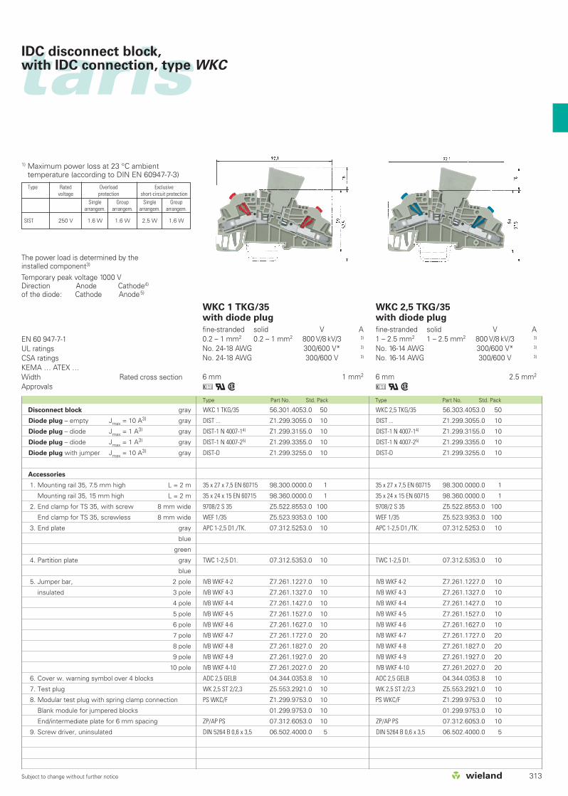
WKC 1 TKG/35with fuse holder
fine-stranded solid V A0.2 – 1 mm2 0.2 – 1 mm2 800 V/8 kV/3 1)
No. 30-18 AWG 600 V* 6.3No. 24-18 AWG 300 V 6.3
6 mm 1 mm2
uqw
WKC 2,5 TKG/35with fuse holder
fine-stranded solid V A1 – 2.5 mm2 1 – 2.5 mm2 800 V/8 kV/3 1)
No. 16-14 AWG 600 V* 6.3No. 16-14 AWG 300 V 6.3
6 mm 2.5 mm2
uqw
EN 60 947-7-1, EN 60 127-6UL ratingsCSA ratingsKEMA … ATEX …Width Rated cross sectionApprovals
Type Part No. Std. Pack Type Part No. Std. Pack
WKC 2,5 TKG/35 56.303.4053.0 50
Si ST Z1.299.4055.0 10
Si ST LED Z1.299.4155.0 10
Si ST GL Z1.299.4255.0 10
35 x 27 x 7,5 EN 60715 98.300.0000.0 1
35 x 24 x 15 EN 60715 98.360.0000.0 1
9708/2 S 35 Z5.522.8553.0 100
WEF 1/35 Z5.523.9353.0 100
APC 1-2,5 D1./TK. 07.312.5253.0 10
TWC 1-2,5 D1. 07.312.5353.0 10
IVB WKF 4-2 Z7.261.1227.0 10
IVB WKF 4-3 Z7.261.1327.0 10
IVB WKF 4-4 Z7.261.1427.0 10
IVB WKF 4-5 Z7.261.1527.0 10
IVB WKF 4-6 Z7.261.1627.0 10
IVB WKF 4-7 Z7.261.1727.0 20
IVB WKF 4-8 Z7.261.1827.0 20
IVB WKF 4-9 Z7.261.1927.0 20
IVB WKF 4-10 Z7.261.2027.0 20
ADC 2,5 GELB 04.344.0353.8 10
WK 2,5 ST 2/2,3 Z5.553.2921.0 10
PS WKC/F Z1.299.9753.0 10
01.299.9753.0 10
ZP/AP PS 07.312.6053.0 10
DIN 5264 B 0,6 x 3,5 06.502.4000.0 5
WKC 1 TKG/35 56.301.4053.0 50
Si ST Z1.299.4055.0 10
Si ST LED Z1.299.4155.0 10
Si ST GL Z1.299.4255.0 10
35 x 27 x 7,5 EN 60715 98.300.0000.0 1
35 x 24 x 15 EN 60715 98.360.0000.0 1
9708/2 S 35 Z5.522.8553.0 100
WEF 1/35 Z5.523.9353.0 100
APC 1-2,5 D1./TK. 07.312.5253.0 10
TWC 1-2,5 D1. 07.312.5353.0 10
IVB WKF 4-2 Z7.261.1227.0 10
IVB WKF 4-3 Z7.261.1327.0 10
IVB WKF 4-4 Z7.261.1427.0 10
IVB WKF 4-5 Z7.261.1527.0 10
IVB WKF 4-6 Z7.261.1627.0 10
IVB WKF 4-7 Z7.261.1727.0 20
IVB WKF 4-8 Z7.261.1827.0 20
IVB WKF 4-9 Z7.261.1927.0 20
IVB WKF 4-10 Z7.261.2027.0 20
ADC 2,5 GELB 04.344.0353.8 10
WK 2,5 ST 2/2,3 Z5.553.2921.0 10
PS WKC/F Z1.299.9753.0 10
01.299.9753.0 10
ZP/AP PS 07.312.6053.0 10
DIN 5264 B 0,6 x 3,5 06.502.4000.0 5
*300 V for use group C
600 V for use group D, E
When selecting G fuse inserts, make sure that thespecified maximum power loss is not exceeded.1)
The current is determined by the inserted fuse.1)
The voltage range is determined by the built-in LEDdisplay.2)
Depending on the application and the installationmethod, the conditions for temperature rise mustbe checked in the closed fuse holders.Higher ambient temperatures are an additional loadfor the fuse inserts. Therefore, the reduction of therated current must be considered accordingly inthese applications.Indicator (24 V) Lamp color: red
Power consumption: 10.3 mAIndicator (220 V) Lamp color: red
Power consumption: 0.3 mA
Disconnect block gray
Fuse holder for fuse 5 x 20 gray
Fuse holder with indicator (24 V)2) gray
Fuse holder with indicator (220 V)2) gray
Accessories
1. Mounting rail 35, 7.5 mm high L = 2 m
Mounting rail 35, 15 mm high L = 2 m
2. End clamp for TS 35, with screw 8 mm wide
End clamp for TS 35, screwless 8 mm wide
3. End plate gray
blue
green
4. Partition plate gray
blue
5. Jumper bar, 2 pole
insulated 3 pole
4 pole
5 pole
6 pole
7 pole
8 pole
9 pole
10 pole
6. Cover w. warning symbol over 4 blocks
7. Test plug
8. Modular test plug with spring clamp connection
Blank module for jumpered blocks
End/intermediate plate for 6 mm spacing
9. Screw driver, uninsulated
Marking accessories also see page 326-327
313Subject to change without further notice
tarisIDC disconnect block,with IDC connection, type WKC
WKC 1 TKG/35with diode plug
fine-stranded solid V A0.2 – 1 mm2 0.2 – 1 mm2 800 V/8 kV/3 3)
No. 24-18 AWG 300/600 V* 3)
No. 24-18 AWG 300/600 V 3)
6 mm 1 mm2
uqw
WKC 2,5 TKG/35with diode plug
fine-stranded solid V A1 – 2.5 mm2 1 – 2.5 mm2 800 V/8 kV/3 3)
No. 16-14 AWG 300/600 V* 3)
No. 16-14 AWG 300/600 V 3)
6 mm 2.5 mm2
uqw
EN 60 947-7-1UL ratingsCSA ratingsKEMA … ATEX …Width Rated cross sectionApprovals
Type Part No. Std. Pack Type Part No. Std. Pack
WKC 1 TKG/35 56.301.4053.0 50
DIST ... Z1.299.3055.0 10
DIST-1 N 4007-14) Z1.299.3155.0 10
DIST-1 N 4007-25) Z1.299.3355.0 10
DIST-D Z1.299.3255.0 10
35 x 27 x 7,5 EN 60715 98.300.0000.0 1
35 x 24 x 15 EN 60715 98.360.0000.0 1
9708/2 S 35 Z5.522.8553.0 100
WEF 1/35 Z5.523.9353.0 100
APC 1-2,5 D1./TK. 07.312.5253.0 10
TWC 1-2,5 D1. 07.312.5353.0 10
IVB WKF 4-2 Z7.261.1227.0 10
IVB WKF 4-3 Z7.261.1327.0 10
IVB WKF 4-4 Z7.261.1427.0 10
IVB WKF 4-5 Z7.261.1527.0 10
IVB WKF 4-6 Z7.261.1627.0 10
IVB WKF 4-7 Z7.261.1727.0 20
IVB WKF 4-8 Z7.261.1827.0 20
IVB WKF 4-9 Z7.261.1927.0 20
IVB WKF 4-10 Z7.261.2027.0 20
ADC 2,5 GELB 04.344.0353.8 10
WK 2,5 ST 2/2,3 Z5.553.2921.0 10
PS WKC/F Z1.299.9753.0 10
01.299.9753.0 10
ZP/AP PS 07.312.6053.0 10
DIN 5264 B 0,6 x 3,5 06.502.4000.0 5
WKC 2,5 TKG/35 56.303.4053.0 50
DIST ... Z1.299.3055.0 10
DIST-1 N 4007-14) Z1.299.3155.0 10
DIST-1 N 4007-25) Z1.299.3355.0 10
DIST-D Z1.299.3255.0 10
35 x 27 x 7,5 EN 60715 98.300.0000.0 1
35 x 24 x 15 EN 60715 98.360.0000.0 1
9708/2 S 35 Z5.522.8553.0 100
WEF 1/35 Z5.523.9353.0 100
APC 1-2,5 D1./TK. 07.312.5253.0 10
TWC 1-2,5 D1. 07.312.5353.0 10
IVB WKF 4-2 Z7.261.1227.0 10
IVB WKF 4-3 Z7.261.1327.0 10
IVB WKF 4-4 Z7.261.1427.0 10
IVB WKF 4-5 Z7.261.1527.0 10
IVB WKF 4-6 Z7.261.1627.0 10
IVB WKF 4-7 Z7.261.1727.0 20
IVB WKF 4-8 Z7.261.1827.0 20
IVB WKF 4-9 Z7.261.1927.0 20
IVB WKF 4-10 Z7.261.2027.0 20
ADC 2,5 GELB 04.344.0353.8 10
WK 2,5 ST 2/2,3 Z5.553.2921.0 10
PS WKC/F Z1.299.9753.0 10
01.299.9753.0 10
ZP/AP PS 07.312.6053.0 10
DIN 5264 B 0,6 x 3,5 06.502.4000.0 5
The power load is determined by the installed component3)
Temporary peak voltage 1000 VDirection Anode Cathode4)
of the diode: Cathode Anode5)
Type Rated Overload Exclusivevoltage protection short-circuit protection
Single Group Single Grouparrangem. arrangem. arrangem. arrangem.
SIST 250 V 1.6 W 1.6 W 2.5 W 1.6 W
1) Maximum power loss at 23 °C ambienttemperature (according to DIN EN 60947-7-3)
Disconnect block gray
Diode plug – empty Jmax = 10 A3) gray
Diode plug – diode Jmax = 1 A3) gray
Diode plug – diode Jmax = 1 A3) gray
Diode plug with jumper Jmax = 10 A3) gray
Accessories
1. Mounting rail 35, 7.5 mm high L = 2 m
Mounting rail 35, 15 mm high L = 2 m
2. End clamp for TS 35, with screw 8 mm wide
End clamp for TS 35, screwless 8 mm wide
3. End plate gray
blue
green
4. Partition plate gray
blue
5. Jumper bar, 2 pole
insulated 3 pole
4 pole
5 pole
6 pole
7 pole
8 pole
9 pole
10 pole
6. Cover w. warning symbol over 4 blocks
7. Test plug
8. Modular test plug with spring clamp connection
Blank module for jumpered blocks
End/intermediate plate for 6 mm spacing
9. Screw driver, uninsulated
314 Subject to change without further notice
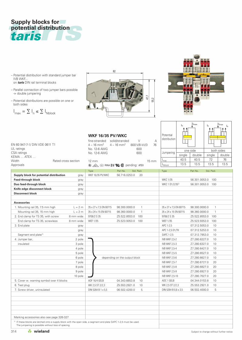
taristaris Supply blocks for potential distribution
WKF 16/35 PV/WKC
fine-stranded solid/stranded V A4 – 16 mm2 4 – 16 mm2 800 V/8 kV/3 76No. 12-6 AWG 600No. 12-6 AWG 600
12 mm 15 mm
agovIqw pending: C
EN 60 947-7-1/ DIN VDE 0611 T1UL ratingsCSA ratingsKEMA … ATEX …Width Rated cross sectionApprovals
Type Part No. Std. Pack Type Part No. Std. Pack
– Potential distribution with standard jumper barIVB WKF... on taris DIN rail terminal blocks
– Parallel connection of two jumper bars possible–> double jumpering
– Potential distributions are possible on one orboth sides
Imax = ∑ In ≤ ∑ INblock
Potentialdistribution
Jumperingone side both sides
single double single doubleImax 40.5 40.5 72 76INblock 13.5 13.5 13.5 13.5
Supply block for potential distribution gray
Feed-through block gray
Duo feed-through block gray
Knife edge disconnect block gray
Disconnect block gray
Accessories
1. Mounting rail 35, 7.5 mm high L = 2 m
Mounting rail 35, 15 mm high L = 2 m
2. End clamp for TS 35, with screw 8 mm wide
End clamp for TS 35, screwless 8 mm wide
3. End plate gray
gray
Segment end plate1) gray
4. Jumper bar, 2 pole
insulated 3 pole
4 pole
5 pole
6 pole
7 pole
8 pole
9 pole
10 pole
5. Cover w. warning symbol over 4 blocks
6. Test plug
7. Screw driver, uninsulated
Marking accessories also see page 326-3271) If these blocks are latched onto a supply block with the open side, a segment end plate SAPC 1-2,5 must be used.
The jumpering is possible without loss of spacing.
ADF 16/4 GELB 04.343.6653.8 10
WK 2,5 ST 2/2,3 Z5.553.2921.0 10
DIN 5264 B 1 x 5,5 06.502.4200.0 5
depending on the output block
WKF 16/35 PV/WKC 56.716.0253.0 20
35 x 27 x 7,5 EN 60715 98.300.0000.0 1
35 x 24 x 15 EN 60715 98.360.0000.0 1
9708/2 S 35 Z5.522.8553.0 100
WEF 1/35 Z5.523.9353.0 100
WKC 1/35 56.301.0053.0 100
WKC 1 D1/2/351) 56.301.0053.0 100
35 x 27 x 7,5 EN 60715 98.300.0000.0 1
35 x 24 x 15 EN 60715 98.360.0000.0 1
9708/2 S 35 Z5.522.8553.0 100
WEF 1/35 Z5.523.9353.0 100
APC 1-2,5 07.312.5053.0 10
APC 1-2,5 D1/TK 07.312.5253.0 10
SAPC 1-2,5 07.312.7953.0 10
IVB WKF 2,5-2 Z7.280.6227.0 10
IVB WKF 2,5-3 Z7.280.6327.0 10
IVB WKF 2,5-4 Z7.280.6427.0 10
IVB WKF 2,5-5 Z7.280.6527.0 10
IVB WKF 2,5-6 Z7.280.6627.0 10
IVB WKF 2,5-7 Z7.280.6727.0 20
IVB WKF 2,5-8 Z7.280.6827.0 20
IVB WKF 2,5-9 Z7.280.6927.0 20
IVB WKF 2,5-10 Z7.280.7027.0 20
ADC 1 GELB 04.344.0153.8 10
WK 2,5 ST 2/2,3 Z5.553.2921.0 10
DIN 5264 B 0,6 x 3,5 06.502.4000.0 5

tarisSupply blocks for potential distribution
315Subject to change without further notice
Type Part No. Std. Pack Type Part No. Std. Pack Type Part No. Std. Pack
WKC 2,5 TKM/351) 56.303.2053.0 50
WKC 2,5 TKG/351) 56.303.4053.0 50
35 x 27 x 7,5 EN 60715 98.300.0000.0 1
35 x 24 x 15 EN 60715 98.360.0000.0 1
9708/2 S 35 Z5.522.8553.0 100
WEF 1/35 Z5.523.9353.0 100
APC 1-2,5 07.312.5053.0 10
APC 1-2,5 D1/TK 07.312.5253.0 10
SAPC 1-2,5 07.312.7953.0 10
IVB WKF 4-2 Z7.261.1227.0 10
IVB WKF 4-3 Z7.261.1327.0 10
IVB WKF 4-4 Z7.261.1427.0 10
IVB WKF 4-5 Z7.261.1527.0 10
IVB WKF 4-6 Z7.261.1627.0 10
IVB WKF 4-7 Z7.261.1727.0 20
IVB WKF 4-8 Z7.261.1827.0 20
IVB WKF 4-9 Z7.261.1927.0 20
IVB WKF 4-10 Z7.261.2027.0 20
ADC 2,5 GELB 04.344.0353.8 10
WK 2,5 ST 2/2,3 Z5.553.2921.0 10
DIN 5264 B 0,6 x 3,5 06.502.4000.0 5
WKC 2,5/35 56.303.0053.0 100
WKC 2,5 D1/2/351) 56.303.5053.0 50
35 x 27 x 7,5 EN 60715 98.300.0000.0 1
35 x 24 x 15 EN 60715 98.360.0000.0 1
9708/2 S 35 Z5.522.8553.0 100
WEF 1/35 Z5.523.9353.0 100
APC 1-2,5 07.312.5053.0 10
APC 1-2,5 D1/TK 07.312.5253.0 10
SAPC 1-2,5 07.312.7953.0 10
IVB WKF 4-2 Z7.261.1227.0 10
IVB WKF 4-3 Z7.261.1327.0 10
IVB WKF 4-4 Z7.261.1427.0 10
IVB WKF 4-5 Z7.261.1527.0 10
IVB WKF 4-6 Z7.261.1627.0 10
IVB WKF 4-7 Z7.261.1727.0 20
IVB WKF 4-8 Z7.261.1827.0 20
IVB WKF 4-9 Z7.261.1927.0 20
IVB WKF 4-10 Z7.261.2027.0 20
ADC 2,5 GELB 04.344.0353.8 10
WK 2,5 ST 2/2,3 Z5.553.2921.0 10
DIN 5264 B 0,6 x 3,5 06.502.4000.0 5
WKC 1 TKM/351) 56.301.2053.0 50
WKC 1 TKG/351) 56.301.4053.0 50
35 x 27 x 7,5 EN 60715 98.300.0000.0 1
35 x 24 x 15 EN 60715 98.360.0000.0 1
9708/2 S 35 Z5.522.8553.0 100
WEF 1/35 Z5.523.9353.0 100
APC 1-2,5 D1/TK 07.312.5253.0 10
SAPC 1-2,5 07.312.7953.0 10
IVB WKF 4-2 Z7.261.1227.0 10
IVB WKF 4-3 Z7.261.1327.0 10
IVB WKF 4-4 Z7.261.1427.0 10
IVB WKF 4-5 Z7.261.1527.0 10
IVB WKF 4-6 Z7.261.1627.0 10
IVB WKF 4-7 Z7.261.1727.0 20
IVB WKF 4-8 Z7.261.1827.0 20
IVB WKF 4-9 Z7.261.1927.0 20
IVB WKF 4-10 Z7.261.2027.0 20
ADC 1 GELB 04.344.0153.8 10
WK 2,5 ST 2/2,3 Z5.553.2921.0 10
DIN 5264 B 0,6 x 3,5 06.502.4000.0 5
*) For disconnect blocks with a fuse disconnect lever, the ratedcurrent is determined by the integrated fuse. (see page 297)
Potentialdistribution
Jumperingone side both sides
single double single doubleImax 40.5 40.5 72 76INblock 13.5* 13.5* 13.5* 13.5*
Potentialdistribution
Jumperingone side both sides
single double single doubletImax 64 72 76 76INblock 24 24 24 24
Potentialdistribution
Jumperingone side both sides
single double single doubleImax 64 72 76 76INblock 20* 20* 20* 20*

taristaris HYBRID
Hybrid DIN rail terminal blockswith IDC and screw technology, type WKC...S/C
316 Subject to change without further notice
0.2........2.5mm2
0.2........6mm2
10 20 30 40 50 60 70 80 90 100 %
taris
60%
With taris HYBRID all the benefits of using IDC technology can be realized for factorywiring. In the same block, the field side can be terminated with familiar screwtechnology.
taris HYBRID offers...
... for factory wiring
IDC technology
User-friendly
Reduced wiring times
Compact design
Screwdriver guide
Application advantages
No special tools required
No stripping necessary
Reduces panel space
Indicates open or closed state of thecontact
... for field wiring
Screw technology
TOP entry system
Wide range of conductor types
Well known termination technology
Wire and screwdriver entry in sameplane
Ease of wiring in small confinedspacesUse of any conductor insulation type
WKC 1 S/C..
solid/stranded copper
stranded coppersolid copper
stranded copper with ferrules
torque specification
Terminal variations
Connection and wire gauge
C = 0.2 – 1 mm2 / AWG 24-18
S = 0.5 – 2.5 mm2 / AWG 22-12S = 0.5 – 4 mm2 / AWG 22-12S = 0.5 – 2.5 mm2 / AWG 22-12
S = 0.4 – 0.6 Nm (M2.5)
Feed-through and ground
Identification in the type descriptionC = IDC technologyS = screw connection
Indication of the positionWKC 1... Red indicatorWKC 2.5... Blue indicator
WKC 2,5 S/C..
solid/stranded copper
stranded coppersolid copperr
stranded copper with ferrules
torque specification
Connection and wire gauge
C = 1 – 2.5 mm2 / AWG 16-14
S = 0.5 – 4 mm2 / AWG 22-10S = 0.5 – 6 mm2 / AWG 22-10S = 0.5 – 4 mm2 / AWG 22-10
S = 0.5 – 0.7 Nm (M3)
wiringwith
time saving
traditional wiring
time
317Subject to change without further notice
tarisHybrid DIN rail terminal blockswith IDC and screw technology, type WKC...S/C
Note
The information regarding cross-sectionalareas and connection types pertains towires without ferrules. Ferrules are notneccessary for secure connection.
The voltage ratings apply to the terminalsin their intended application. Whendifferent products are mounted adjacentto each other, the proper isolationdistances must be adhered to. For thispurpose, Wieland offers a large selectionof appopriate accessories.
A detailed description of technical data,the standards requirements, and theapplication conditions can be found incatalog section facts & DATA.
DQS certificates for all products
Quality standard as per DIN ISO 9001 in Development, Production, Assembly Continued control of the quality standard
by means of regular internal and externalquality audits
Compatible with certificates of othercountries:– BSI Certificate, Great Britain– SQS Certificate, Switzerland– Aib-Vincotte Certificate, Belgium– ÖQS Certificate, Austria
Marking capability
Single marking tags
Marking tag strips (10 tags per strip) torapidly identify the blocks and circuitry
Tear-off marking strip for marking up to 3 digits per terminal block
Marking facility is down the center so thatthe marking tag is not covered by theconductor.
Cover with warning symbol
Cover with warning symbol ADC to snapon to blocks which remain live after themains have been switched off (VDE 0113)
Cover can only be removed with a screwdriver
Cross connection
Insulated cross connectors IVB WKF... arefully protected against accidental contact.
Partition plates are therefore not requiredbetween adjacent jumper bars
The cross connectors IVB WKF... carry thesame rated current as the jumpered block
Flexible potential distribution throughstaggered and chain arrangement of thecross connectors in 3 jumpering channelsper block
Materials
Metal parts:
Special alloys enable low feed-throughresistance and provide a gas-tightcontact area:
Clamping body: tin-plated copper
Busbar: tin-plated copper
Mounting foot: tin-plated brass
Insulating material:
Polyamide has excellent electrical, chemical and mechanical characteristics.
Insulating housings: Polyamide 66/6
Tracking resistance: CTI 600
Flammability class: UL 94-V0
(also see section facts & DATA)
Test plug
taris provides built-in test points for all itsblocks, therefore measurements can beperformed without having to remove thewiring.
Entry guides on each side of the terminalblocks allow measurement with standardØ 2.3 mm test probes and test plugs formaintenance and troubleshooting.
Modular test plug
The modular test plug enables testsand measurements to be performedin the jumpering channel. The modulardesign in 5 and 6 mm spacing withblank modules for jumpered blocksand the jumpering option of the testplug itself enable individual testconfiguration and quick final testingduring manufacturing.
Our wieplan software helps to planyour own terminal block assembly (see page 36/37).

318 Subject to change without further notice
WKC 1 S/C/35
fine-stranded solid V A0.21 – 1 mm2 0.21 – 1 mm2 800 V/8 kV/3 13.50.5 – 2.5 mm2 0.5 – 4 mm2 800 V/8 kV/3 13.5No. 24-18 AWG 600 V 13No. 22-12 AWG 600 V 13
5 mm 10 mm
qw
WKC 2,5 S/C/35
fine-stranded solid V A1 – 2.5 mm2 1 – 2.5 mm2 800 V/8 kV/3 240.5 – 4 mm2 0.5 – 6 mm2 800 V/8 kV/3 24No. 22-12 AWG 600 V 20No. 22-10 AWG 600 V 20
6 mm 10 mm
qw
EN 60 947-7-1 IDC
EN 60 947-7-1 Screw
UL ratingsCSA ratingsKEMA … ATEX …Width Rated cross sectionApprovals
Type Part No. Std. Pack Type Part No. Std. Pack
WKC 1 S/C/35 56.351.0053.0 100
WKC 1 S/C/35 BLAU 56.351.0053.6 100
35 x 27 x 7,5 EN 60715 98.300.0000.0 1
35 x 24 x 15 EN 60715 98.360.0000.0 1
9708/2 S 35 Z5.522.8553.0 100
WEF 1/35 Z5.523.9353.0 100
APC 1-2,5 07.312.5053.0 10
APC 1-2,5 BLAU 07.312.5053.6 10
TWC 1-2,5 07.312.5153.0 10
TWC 1-2,5 BLAU 07.312.5153.6 10
IVB WKF 2,5-2 Z7.280.6227.0 10
IVB WKF 2,5-3 Z7.280.6327.0 10
IVB WKF 2,5-4 Z7.280.6427.0 10
IVB WKF 2,5-5 Z7.280.6527.0 10
IVB WKF 2,5-6 Z7.280.6627.0 10
IVB WKF 2,5-7 Z7.280.6727.0 20
IVB WKF 2,5-8 Z7.280.6827.0 20
IVB WKF 2,5-9 Z7.280.6927.0 20
IVB WKF 2,5-10 Z7.280.7027.0 20
ADC 1/4 GELB 04.344.0153.8 10
ADF 2,5/4 GELB 04.343.6053.8 10
WK 2,5 ST 2/2,3 Z5.553.2921.0 10
PS WKC/F Z1.299.9753.0 10
01.299.9753.0 10
ZP/AP PS 07.312.6053.0 10
DIN 5264 B 0,6 x 3,5 06.502.4000.0 5
DIN 5264 B 0,6 x 3,5 M 06.502.5000.0 10
WKC 2,5 S/C/35 56.353.0053.0 100
WKC 2,5 S/C/35 56.353.0053.6 100
35 x 27 x 7,5 EN 60715 98.300.0000.0 1
35 x 24 x 15 EN 60715 98.360.0000.0 1
9708/2 S 35 Z5.522.8553.0 100
WEF 1/35 Z5.523.9353.0 100
APC 1-2,5 07.312.5053.0 10
APC 1-2,5 BLAU 07.312.5053.6 10
TWC 1-2,5 07.312.5153.0 10
TWC 1-2,5 BLAU 07.312.5153.6 10
IVB WKF 4-2 Z7.261.1227.0 10
IVB WKF 4-3 Z7.261.1327.0 10
IVB WKF 4-4 Z7.261.1427.0 10
IVB WKF 4-5 Z7.261.1527.0 10
IVB WKF 4-6 Z7.261.1627.0 10
IVB WKF 4-7 Z7.261.1727.0 20
IVB WKF 4-8 Z7.261.1827.0 20
IVB WKF 4-9 Z7.261.1927.0 20
IVB WKF 4-10 Z7.261.2027.0 20
ADC 2,5 GELB 04.344.0353.8 10
ADF 4/4 GELB 04.343.6153.8 10
WK 2,5 ST 2/2,3 Z5.553.2921.0 10
PS WKC/F Z1.299.9753.0 10
01.299.9753.0 10
ZP/AP PS 07.312.6053.0 10
DIN 5264 B 0,6 x 3,5 06.502.4000.0 5
DIN 5264 B 0,6 x 3,5 M 06.502.5000.0 10
taristaris HYBRID
Hybrid feed-through blockswith IDC and spring clamp connection, type WKC...F/C
Termination point “S” = screw technologyTermination point “C” = IDC technology
Feed-through block gray
Feed-through block blue
Ground block green/yellow
Accessories
1. Mounting rail 35, 7.5 mm high L = 2 m
Mounting rail 35, 15 mm high L = 2 m
2. End clamp for TS 35, with screw 8 mm wide
End clamp for TS 35, screwless 8 mm wide
3. End plate 1.5 mm wide gray
1.5 mm wide blue
1.5 mm wide green
4. Partition plate 1.5 mm wide gray
1.5 mm wide blue
5. Jumper bar, 2 pole
insulated 3 pole
4 pole
5 pole
6 pole
7 pole
8 pole
9 pole
10 pole
6. Cover w. warning symbol over 4 blocks
Termination point “C”
Termination point “S”
7. Test plug
8. Modular test plug with spring clamp connection
Blank module for jumpered blocks
End/intermediate plate for 6 mm spacing
9. Screw driver, uninsulated
Screw driver, uninsulated, MINI
Marking accessories also see page 326-327

319Subject to change without further notice
WKC 1 S/C/SL/35
fine-stranded solid V A0.21 – 1 mm2 0.21 – 1 mm2 800 V/8 kV/3 13.50.5 – 2.5 mm2 0.5 – 4 mm2 800 V/8 kV/3 13.5No. 24-18 AWGNo. 22-12 AWG
5 mm 10 mm
qw
WKC 2,5 S/C/SL/35
fine-stranded solid V A1 – 2.5 mm2 1 – 2.5 mm2 800 V/8 kV/3 240.5 – 4 mm2 0.5 – 6 mm2 800 V/8 kV/3 24No. 22-12 AWGNo. 22-10 AWG
6 mm 10 mm
qw
EN 60 947-7-1 IDC
EN 60 947-7-1 Screw
UL ratingsCSA ratingsKEMA … ATEX …Width Rated cross sectionApprovals
Type Part No. Std. Pack Type Part No. Std. Pack
WKC 1 S/C/SL/35 56.351.9053.0 100
35 x 27 x 7,5 EN 60715 98.300.0000.0 1
35 x 24 x 15 EN 60715 98.360.0000.0 1
9708/2 S 35 Z5.522.8553.0 100
WEF 1/35 Z5.523.9353.0 100
APC 1-2,5 GRÜN 07.312.5053.7 10
ADC 1/4 GELB 04.344.0153.8 10
ADF 2,5/4 GELB 04.343.6053.8 10
WK 2,5 ST 2/2,3 Z5.553.2921.0 10
PS WKC/F Z1.299.9753.0 10
01.299.9753.0 10
ZP/AP PS 07.312.6053.0 10
DIN 5264 B 0,6 x 3,5 06.502.4000.0 5
DIN 5264 B 0,6 x 3,5 M 06.502.5000.0 10
WKC 2,5 S/C/SL/35 56.353.9053.0 100
35 x 27 x 7,5 EN 60715 98.300.0000.0 1
35 x 24 x 15 EN 60715 98.360.0000.0 1
9708/2 S 35 Z5.522.8553.0 100
WEF 1/35 Z5.523.9353.0 100
APC 1-2,5 GRÜN 07.312.5053.7 10
ADC 2,5 GELB 04.344.0353.8 10
ADF 4/4 GELB 04.343.6153.8 10
WK 2,5 ST 2/2,3 Z5.553.2921.0 10
PS WKC/F Z1.299.9753.0 10
01.299.9753.0 10
ZP/AP PS 07.312.6053.0 10
DIN 5264 B 0,6 x 3,5 06.502.4000.0 5
DIN 5264 B 0,6 x 3,5 M 06.502.5000.0 10
tarisHybrid feed-through blockswith IDC and spring clamp connection, type WKC...F/C
Termination point “S” = screw technologyTermination point “C” = IDC technology
Feed-through block gray
Feed-through block blue
Ground block green/yellow
Accessories
1. Mounting rail 35, 7.5 mm high L = 2 m
Mounting rail 35, 15 mm high L = 2 m
2. End clamp for TS 35, with screw 8 mm wide
End clamp for TS 35, screwless 8 mm wide
3. End plate 1.5 mm wide gray
1.5 mm wide blue
1.5 mm wide green
4. Partition plate 1.5 mm wide gray
1.5 mm wide blue
5. Jumper bar, 2 pole
insulated 3 pole
4 pole
5 pole
6 pole
7 pole
8 pole
9 pole
10 pole
6. Cover w. warning symbol over 4 blocks
Termination point “C”
Termination point “S”
7. Test plug
8. Modular test plug with spring clamp connection
Blank module for jumpered blocks
End/intermediate plate for 6 mm spacing
9. Screw driver, uninsulated
Screw driver, uninsulated, MINI

320 Subject to change without further notice
taristaris HYBRID
Hybrid feed-through terminalswith IDC and spring clamp connection, type WKC...F/C
With taris HYBRID all the benefits of using IDC technology can be realized for factorywiring. In the same block, the field side can be terminated with familiar screwtechnology.
taris HYBRID offers...
... for factory wiring
IDC technology
User-friendly
Reduced wiring times
Compact design
Screwdriver guide
Application advantages
No special tools required
No stripping necessary
Reduces panel space
Indicates open or closed state of thecontact
... for field wiring
Spring clamp connection technology
TOP entry system
Wide range of conductor types
Universally known and acceptedconnection technique
Clear wiring in difficult and confined wiring applications
No restriction of the conductors withregard to the selected insulatingmaterial
WKC 1 F/C..
solid or fine-stranded copper conductor
fine-stranded copper conductorsolid copper conductor
fine-stranded copper conductor withferrule
Terminal variations
Termination points
C = 0.2 – 1 mm2 / AWG 24-18
F = 0.13 – 4 mm2 / AWG 22-10F = 0.13 – 6 mm2 / AWG 22-10F = 0.13 – 4 mm2 / AWG 22-10
Feed-through and ground
Identification in the type descriptionC = IDC technologyF = spring clamp connection
Indication of the positionWKC 1... red indicatorWKC 2,5... blue indicator
WKC 2,5 F/C..
solid or fine-stranded copper conductor
fine-stranded copper conductorsolid copper conductor
fine-stranded copper conductor withferrule
Termination points
C = 1 – 2.5 mm2 / AWG 16-14
F = 0.13 – 4 mm2 / AWG 22-10F = 0.13 – 6 mm2 / AWG 22-10F = 0.13 – 4 mm2 / AWG 22-10
0.2........2.5mm2
0.2........6mm2
10 20 30 40 50 60 70 80 90 100 %
taris
60%wiringwith
time saving
traditional wiring
time

321Subject to change without further notice
tarisHybrid feed-through terminalswith IDC and spring clamp connection, type WKC...F/C
Note
The information regarding cross-sectio-nal areas and connection types pertainsto wires without ferrules. Ferrules arenot neccessary for secure connection.
The voltage ratings apply to the terminals in their intended application.When different products are mountedadjacent to each other, the properisolation distances must be adhered to.For this purpose, Wieland offers a largeselection of appopriate accessories.
A detailed description of technical data,the standards requirements, and theapplication conditions can be found incatalog section facts & DATA.
DQS certificates for all products
Quality standard as per DIN ISO 9001 in Development, Production, Assembly Continued control of the quality standard
by means of regular internal and externalquality audits
Compatible with certificates of othercountries:– BSI Certificate, Great Britain– SQS Certificate, Switzerland– Aib-Vincotte Certificate, Belgium– ÖQS Certificate, Austria
Marking capability
Single marking tags
Marking tag strips (10 tags per strip) torapidly identify the blocks and circuitry
Tear-off marking strip for marking up to 3 digits per terminal block
Marking facility is down the center so thatthe marking tag is not covered by theconductor.
Cover with warning symbol
Cover with warning symbol ADC to snapon to blocks which remain live after themains have been switched off (VDE 0113)
Cover can only be removed with a screwdriver
Cross connection
Insulated cross connectors IVB WKF... arefully protected against accidental contact.
Partition plates are therefore not requiredbetween adjacent jumper bars
The cross connectors IVB WKF... carry thesame rated current as the jumpered block
Flexible potential distribution throughstaggered and chain arrangement of thecross connectors in 3 jumpering channelsper block
Materials
Metal parts:
Special alloys enable low feed-throughresistance and provide a gas-tightcontact area:
Clamping body: tin-plated copper
Busbar: tin-plated copper
Mounting foot: tin-plated brass
Insulating material:
Polyamide has excellent electrical, chemical and mechanical characteristics.
Insulating housings: Polyamide 66/6
Tracking resistance: CTI 600
Flammability class: UL 94-V0
(also see section facts & DATA)
Test plug
taris provides built-in test points for all itsblocks, therefore measurements can beperformed without having to remove thewiring.
Entry guides on each side of the terminalblocks allow measurement with standardØ 2.3 mm test probes and test plugs formaintenance and troubleshooting.
Modular test plug
The modular test plug enables testsand measurements to be performedin the jumpering channel. The modulardesign in 5 and 6 mm spacing withblank modules for jumpered blocksand the jumpering option of the testplug itself enable individual testconfiguration and quick final testingduring manufacturing.
Our wieplan software helps to planyour own terminal block assembly (see page 36/37).
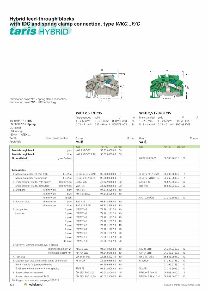
322 Subject to change without further notice
WKC 2,5 F/C/35
fine-stranded solid V A1 – 2.5 mm2 1 – 2.5 mm2 800 V/8 kV/3 240.13 – 4 mm2 0.13 – 6 mm2 800 V/8 kV/3 24
6 mm 11 mm
qw
WKC 2,5 F/C/SL/35
fine-stranded solid V A1 – 2.5 mm2 1 – 2.5 mm2 800 V/8 kV/30.13 – 4 mm2 0.13 – 6 mm2 800 V/8 kV/3
6 mm 11 mm
qw
EN 60 947-7-1 IDC
EN 60 947-7-1 Spring
UL ratingsCSA ratingsKEMA … ATEX …Width Rated cross sectionApprovals
Type Part No. Std. Pack Type Part No. Std. Pack
WKC 2,5 F/C/35 56.333.0053.0 100
WKC 2,5 F/C/35 BLAU 56.333.0053.6 100
35 x 27 x 7,5 EN 60715 98.300.0000.0 1
35 x 24 x 15 EN 60715 98.360.0000.0 1
9708/2 S 35 Z5.522.8553.0 100
WEF 1/35 Z5.523.9353.0 100
APC 1-2,5 07.312.5053.0 10
APC 1-2,5 BLAU 07.312.5053.6 10
TWC 1-2,5 07.312.5153.0 10
TWC 1-2,5 BLAU 07.312.5153.6 10
IVB WKF 4-2 Z7.261.1227.0 10
IVB WKF 4-3 Z7.261.1327.0 10
IVB WKF 4-4 Z7.261.1427.0 10
IVB WKF 4-5 Z7.261.1527.0 10
IVB WKF 4-6 Z7.261.1627.0 10
IVB WKF 4-7 Z7.261.1727.0 20
IVB WKF 4-8 Z7.261.1827.0 20
IVB WKF 4-9 Z7.261.1927.0 20
IVB WKF 4-10 Z7.261.2027.0 20
ADC 2,5 GELB 04.344.0353.8 10
ADF 4/4 GELB 04.343.6153.8 10
WK 2,5 ST 2/2,3 Z5.553.2921.0 10
PS WKC/F Z1.299.9753.0 10
01.299.9753.0 10
ZP/AP PS 07.312.6053.0 10
DIN 5264 B 0,6 x 3,5 06.502.4000.0 5
DIN 5264 B 0,6 x 3,5 M 06.502.5000.0 10
WKC 2,5 F/C/SL/35 56.333.9053.0 100
35 x 27 x 7,5 EN 60715 98.300.0000.0 1
35 x 24 x 15 EN 60715 98.360.0000.0 1
9708/2 S 35 Z5.522.8553.0 100
WEF 1/35 Z5.523.9353.0 100
APC 1-2,5 GRÜN 07.312.5053.7 10
ADC 2,5 GELB 04.344.0353.8 10
ADF 4/4 GELB 04.343.6153.8 10
WK 2,5 ST 2/2,3 Z5.553.2921.0 10
PS WKC/F Z1.299.9753.0 10
01.299.9753.0 10
ZP/AP PS 07.312.6053.0 10
DIN 5264 B 0,6 x 3,5 06.502.4000.0 5
DIN 5264 B 0,6 x 3,5 M 06.502.5000.0 10
taristaris HYBRID
Hybrid feed-through blockswith IDC and spring clamp connection, type WKC...F/C
Termination point “F” = spring clamp connectionTermination point “C” = IDC technology
Feed-through block gray
Feed-through block blue
Ground block green/yellow
Accessories
1. Mounting rail 35, 7.5 mm high L = 2 m
Mounting rail 35, 15 mm high L = 2 m
2. End clamp for TS 35, with screw 8 mm wide
End clamp for TS 35, screwless 8 mm wide
3. End plate 1.5 mm wide gray
1.5 mm wide blue
1.5 mm wide green
4. Partition plate 1.5 mm wide gray
1.5 mm wide blue
5. Jumper bar, 2 pole
insulated 3 pole
4 pole
5 pole
6 pole
7 pole
8 pole
9 pole
10 pole
6. Cover w. warning symbol over 4 blocks
Termination point “C”
Termination point “F”
7. Test plug
8. Modular test plug with spring clamp connection
Blank module for jumpered blocks
End/intermediate plate for 6 mm spacing
9. Screw driver, uninsulated
Screw driver, uninsulated, MINI
Marking accessories also see page 326-327

323Subject to change without further notice
WKC 1 E/F/C/35
WKC 1 D2F/2C/35
fine-stranded solid V A0.21 – 1 mm2 0.21 – 1 mm2 500 V/6 kV/3 240.13 – 4 mm2 0.13 – 6 mm2 500 V/6 kV/3 24
6 mm 11 mm
qw
WKC 1 D2F/2C/SL/35
fine-stranded solid V A1 – 2.5 mm2 1 – 2.5 mm2 500 V/6 kV/30.13 – 4 mm2 0.13 – 6 mm2 500 V/6 kV/3
6 mm 11 mm
qw
EN 60 947-7-1 IDC
EN 60 947-7-1 Spring
UL ratingsCSA ratingsKEMA … ATEX …Width Rated cross sectionApprovals
Type Part No. Std. Pack Type Part No. Std. Pack
WKC 1 E/F/C/35 56.331.7053.0 50
WKC 1 D2F/2C/35 56.331.5153.0 50
WKC 1 D2F/2C/35 BLAU 56.331.5153.6 50
35 x 27 x 7,5 EN 60715 98.300.0000.0 50
35 x 24 x 15 EN 60715 98.360.0000.0 1
9708/2 S 35 Z5.522.8553.0 100
WEF 1/35 Z5.523.9353.0 100
APC 1-2,5 D2/E/F/C 07.312.6553.0 10
APC 1-2,5 D2/E/F/C BLAU 07.312.6553.6 10
TWC 1-2,5 D2/E/F/C 07.312.6653.0 10
TWC 1-2,5 D2/E/F/C BLAU 07.312.6653.6 10
IVB WKF 4-2 Z7.261.1227.0 10
IVB WKF 4-3 Z7.261.1327.0 10
IVB WKF 4-4 Z7.261.1427.0 10
IVB WKF 4-5 Z7.261.1527.0 10
IVB WKF 4-6 Z7.261.1627.0 10
IVB WKF 4-7 Z7.261.1727.0 20
IVB WKF 4-8 Z7.261.1827.0 20
IVB WKF 4-9 Z7.261.1927.0 20
IVB WKF 4-10 Z7.261.2027.0 20
ADC 2,5 GELB 04.344.0353.8 10
ADF 4/4 GELB 04.343.6153.8 10
WK 2,5 ST 2/2,3 Z5.553.2921.0 10
PS WKC/F Z1.299.9753.0 10
01.299.9753.0 10
ZP/AP PS 07.312.6053.0 10
DIN 5264 B 0,6 x 3,5 06.502.4000.0 5
DIN 5264 B 0,6 x 3,5 M 06.502.5000.0 10
WKC 1 D2F/2C/SL/35 56.331.9153.0 50
35 x 27 x 7,5 EN 60715 98.300.0000.0 1
35 x 24 x 15 EN 60715 98.360.0000.0 1
9708/2 S 35 Z5.522.8553.0 100
WEF 1/35 Z5.523.9353.0 100
APC 1-2,5 D2/E/F/C GRÜN 07.312.6553.7 10
ADC 2,5 GELB 04.344.0353.8 10
ADF 4/4 GELB 04.343.6153.8 10
WK 2,5 ST 2/2,3 Z5.553.2921.0 10
PS WKC/F Z1.299.9753.0 10
01.299.9753.0 10
ZP/AP PS 07.312.6053.0 10
DIN 5264 B 0,6 x 3,5 06.502.4000.0 5
DIN 5264 B 0,6 x 3,5 M 06.502.5000.0 10
tarisHybrid feed-through blockswith IDC and spring clamp connection, type WKC...F/C
Termination point “F” = spring clamp connectionTermination point “C” = IDC technology
Variation “E” = 2 independent line feed-throughs
Variation “D2”= Both line feed-throughs are combined in one potential
Multi-tier block gray
Feed-through block gray
Feed-through block blue
Ground block green/yellow
Accessories
1. Mounting rail 35, 7.5 mm high L = 2 m
Mounting rail 35, 15 mm high L = 2 m
2. End clamp for TS 35, with screw 8 mm wide
End clamp for TS 35, screwless 8 mm wide
3. End plate 1.5 mm wide gray
1.5 mm wide blue
1.5 mm wide green
4. Partition plate 1.5 mm wide gray
1.5 mm wide blue
5. Jumper bar, 2 pole
insulated 3 pole
4 pole
5 pole
6 pole
7 pole
8 pole
9 pole
10 pole
6. Cover w. warning symbol over 4 blocks
Termination point “C”
Termination point “F”
7. Test plug
8. Modular test plug with spring clamp connection
Blank module for jumpered blocks
End/intermediate plate for 6 mm spacing
9. Screw driver, uninsulated
Screw driver, uninsulated, MINI

324 Subject to change without further notice
taristarisAccessoriesDIN rail terminal blocks with IDC connection, type WKC
Mounting rail
1. Steel, galv. zinc-plated, dichromated, unslotted L = 2 m
Steel, galv. zinc-plated, dichromated, slotted L = 2 m
2. Steel, unplated unslotted L = 2 m
Steel, unplated slotted L = 2 m
3. Steel, high-temp. zinc-plated unslotted L = 2 m
Steel, high-temp. zinc-plated slotted L = 2 m
4. E copper unslotted L = 2 m
E copper slotted L = 2 m
End clamp
5. End clamp with screw for 35 mm rail 8 mm wide
6. End clamp with screw for 35 mm rail
with marking plate 8/17.5 mm wide
for block rails
7. End clamp, screwless, for 35 mm rail 8 mm wide
8. End clamp, screwless, for 35 mm rail
with marking plate 8/17.5 mm wide
for block rails
9. Bus bar holder, screwless 8 mm wide
Busbar support, including tag 8 mm
10. Clamping screw for mounting rail
11. Optional label carrier
12. Paper markers in perforated sheet form
(1 sheet = 100 Marking tags)
35 x 27 x 15 EN 60715 98.370.0000.0 1
35 x 27 x 15 EN 60715 98.370.1000.0 1
Mounting rail 35 x 7,5
according to DIN EN 60715
35 x 27 x 7,5 EN 60715 98.300.0000.0 1
35 x 27 x 7,5 EN 60715 slotted 98.300.1000.0 1
35 x 27 x 7,5 EN 60715 unslotted 98.300.0010.0 1
Mounting rail 35 x 15
according to DIN EN 60715Type Part No. Std. Pack Type Part No. Std. Pack

325Subject to change without further notice
taris
End clamp for TS 35
screw mountEnd clamp for TS 35
screwless mount
9708/2 S 35 Z5.522.8553.0 100
9708/2 BS/35 69.920.0553.0 100
04.019.0289.0 10
35 x 27 x 15 EN 60715 98.360.0000.0 1
35 x 27 x 15 EN 60715 ZN 98.360.0004.0 1
35 x 27 x 15 EN 60715 CU 98.380.0000.0 10
WEF 1/35 Z5.523.9353.0 100
WEF 1 BS/35 69.920.1053.0 100
WKIF SH/E/35 Z1.108.8453.0 100
69.920.1153.0 100
05.091.0212.0 100
BS/R Z4.243.8453.0 10
04.019.0289.0 10
Mounting rail 35 x 15
according to DIN EN 60715Type Part No. Std. Pack Type Part No. Std. Pack Type Part No. Std. Pack
AccessoriesDIN rail terminal blocks with IDC connection, type WKC

326 Subject to change without further notice
Type Part No. Std. Pack Type Part No. Std. Pack Type Part No. Std. Pack
taristarisTest plug with spring clamp connection
Single pole module
5 mm spacing
PS WKC/F Z1.299.9753.0 10
Blank module for jumpered
blocks 01.299.9753.0 10
End plate and
intermediate plate for 6 mm spacing
ZP/AP PS 07.312.6053.0 10
To achieve a 6 mm spacing, use one partition each
per module
The modular test plug enables testing and measurement
in the jumpering channel without having to remove the
jumpers.
The modular arrangement 5 and 6 mm spacing with
blank modules for jumpered blocks and the
jumpering option of the test plug itself enable individual
test arrangements and quick final testing in
manufacturing.
The test plugs can be marked with attached marking
tags for 5 or 6 mm wide blocks.
Test plug with spring clamp connectionfor WKF/WKC terminal blocks
PS WKC/Ffine-stranded solid V A0.13 - 1.5 mm2 0.13 - 1.5 mm2 400 V 2.5
Marking tag carrierLabel with handling instructions
taris/WKC
For all block widths with 4/6 digits
4 digits
9705 A/4 04.242.0950.0 200
6 digits
9705 A/6 04.242.1250.0 200
Marking tag carrier
45° angle
9705 A/4 W 04.242.2853.0 200
2 x 4 digits, 45°, 5 mm wide
makes the marking legible in every block position
05.563.5700.0 1
45° angle
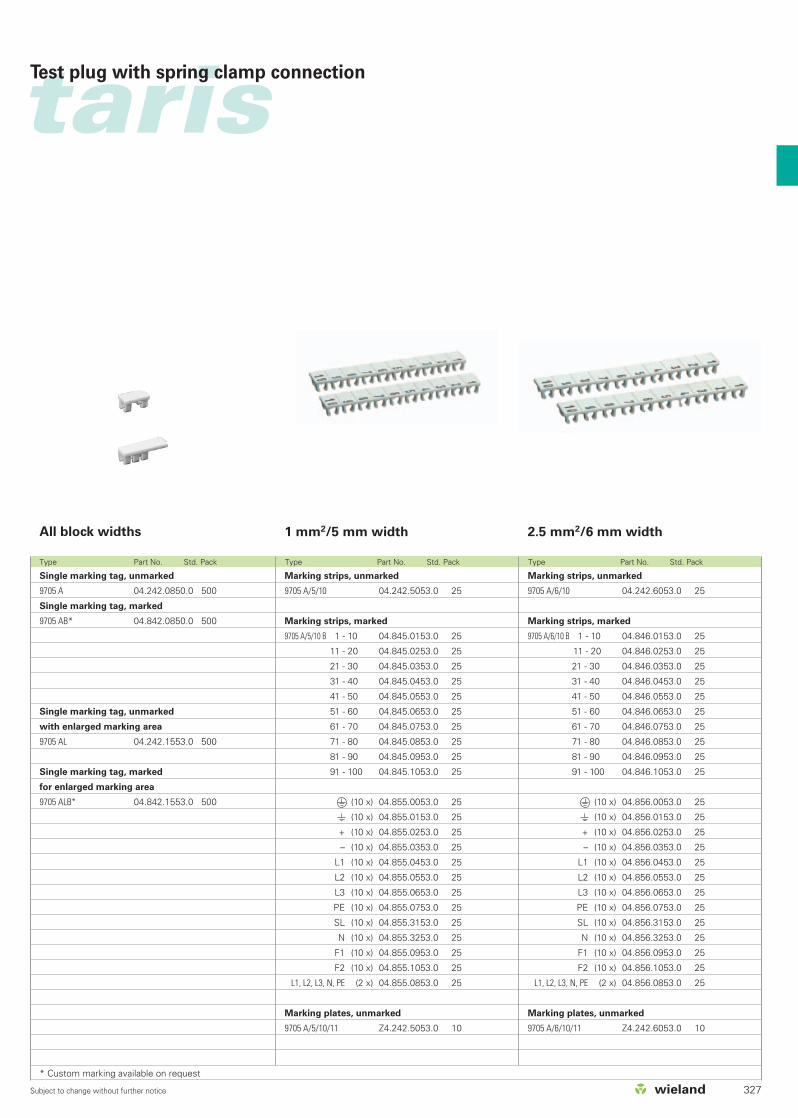
327Subject to change without further notice
Type Part No. Std. Pack Type Part No. Std. Pack Type Part No. Std. Pack
tarisTest plug with spring clamp connection
2.5 mm2/6 mm width1 mm2/5 mm width
Marking strips, unmarked
9705 A/6/10 04.242.6053.0 25
Marking strips, marked
9705 A/6/10 B 1 - 10 04.846.0153.0 25
11 - 20 04.846.0253.0 25
21 - 30 04.846.0353.0 25
31 - 40 04.846.0453.0 25
41 - 50 04.846.0553.0 25
51 - 60 04.846.0653.0 25
61 - 70 04.846.0753.0 25
71 - 80 04.846.0853.0 25
81 - 90 04.846.0953.0 25
91 - 100 04.846.1053.0 25
(10 x) 04.856.0053.0 25
(10 x) 04.856.0153.0 25
+ (10 x) 04.856.0253.0 25
– (10 x) 04.856.0353.0 25
L1 (10 x) 04.856.0453.0 25
L2 (10 x) 04.856.0553.0 25
L3 (10 x) 04.856.0653.0 25
PE (10 x) 04.856.0753.0 25
SL (10 x) 04.856.3153.0 25
N (10 x) 04.856.3253.0 25
F1 (10 x) 04.856.0953.0 25
F2 (10 x) 04.856.1053.0 25
L1, L2, L3, N, PE (2 x) 04.856.0853.0 25
Marking plates, unmarked
9705 A/6/10/11 Z4.242.6053.0 10
Marking strips, unmarked
9705 A/5/10 04.242.5053.0 25
Marking strips, marked
9705 A/5/10 B 1 - 10 04.845.0153.0 25
11 - 20 04.845.0253.0 25
21 - 30 04.845.0353.0 25
31 - 40 04.845.0453.0 25
41 - 50 04.845.0553.0 25
51 - 60 04.845.0653.0 25
61 - 70 04.845.0753.0 25
71 - 80 04.845.0853.0 25
81 - 90 04.845.0953.0 25
91 - 100 04.845.1053.0 25
(10 x) 04.855.0053.0 25
(10 x) 04.855.0153.0 25
+ (10 x) 04.855.0253.0 25
– (10 x) 04.855.0353.0 25
L1 (10 x) 04.855.0453.0 25
L2 (10 x) 04.855.0553.0 25
L3 (10 x) 04.855.0653.0 25
PE (10 x) 04.855.0753.0 25
SL (10 x) 04.855.3153.0 25
N (10 x) 04.855.3253.0 25
F1 (10 x) 04.855.0953.0 25
F2 (10 x) 04.855.1053.0 25
L1, L2, L3, N, PE (2 x) 04.855.0853.0 25
Marking plates, unmarked
9705 A/5/10/11 Z4.242.5053.0 10
All block widths
Single marking tag, unmarked
9705 A 04.242.0850.0 500
Single marking tag, marked
9705 AB* 04.842.0850.0 500
Single marking tag, unmarked
with enlarged marking area
9705 AL 04.242.1553.0 500
Single marking tag, marked
for enlarged marking area
9705 ALB* 04.842.1553.0 500
* Custom marking available on request