tapered thread couplers - ancon · pdf filetorque wrench. the range of tapered thread couplers...
TRANSCRIPT
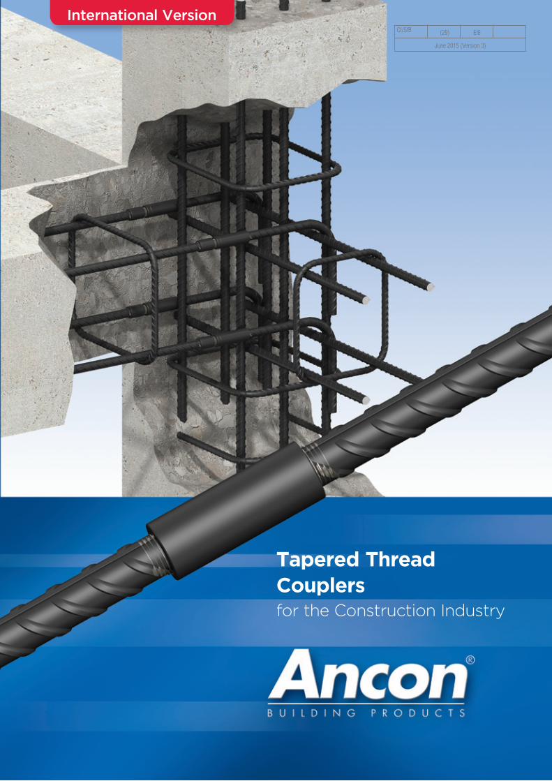
Tapered Thread Couplersfor the Construction Industry
CI/SfB (29) Et6
June 2015 (Version 3)
International Version
2 Tel: +44 (0) 114 275 5224 www.ancon.co.uk
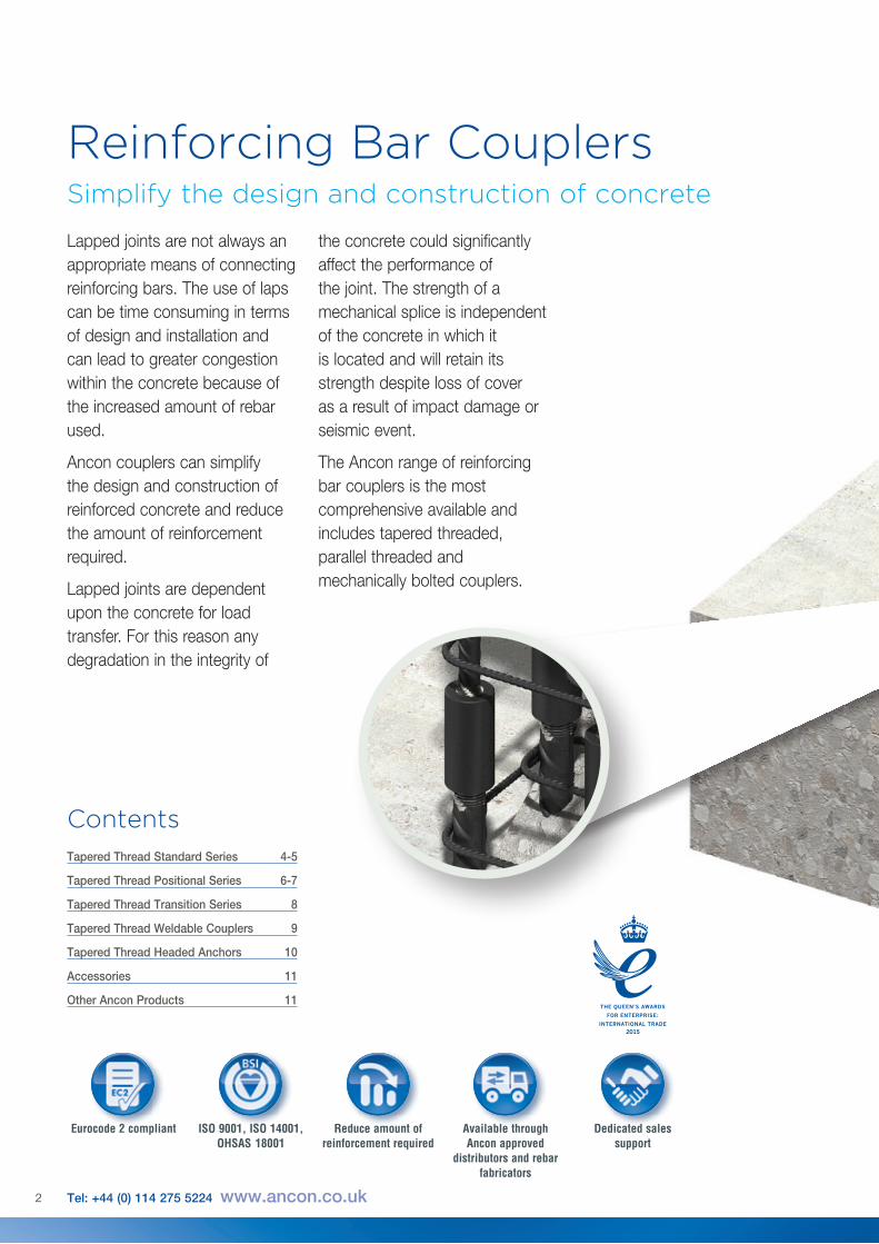
Lapped joints are not always an appropriate means of connecting reinforcing bars. The use of laps can be time consuming in terms of design and installation and can lead to greater congestion within the concrete because of the increased amount of rebar used.
Ancon couplers can simplify the design and construction of reinforced concrete and reduce the amount of reinforcement required.
Lapped joints are dependent upon the concrete for load transfer. For this reason any degradation in the integrity of
the concrete could significantly affect the performance of the joint. The strength of a mechanical splice is independent of the concrete in which it is located and will retain its strength despite loss of cover as a result of impact damage or seismic event.
The Ancon range of reinforcing bar couplers is the most comprehensive available and includes tapered threaded, parallel threaded and mechanically bolted couplers.
Reinforcing Bar Couplers Simplify the design and construction of concrete
Reduce amount of reinforcement required
Available through Ancon approved
distributors and rebar fabricators
Dedicated sales support
Eurocode 2 compliant ISO 9001, ISO 14001, OHSAS 18001
Tapered Thread Standard Series 4-5
Tapered Thread Positional Series 6-7
Tapered Thread Transition Series 8
Tapered Thread Weldable Couplers 9
Tapered Thread Headed Anchors 10
Accessories 11
Other Ancon Products 11
Contents
3

Reinforcing Bar Couplers
4 Tel: +44 (0) 114 275 5224 www.ancon.co.uk
Tapered ThreadThe Ancon range of Tapered Thread couplers is designed to suit the majority of applications which call for the joining of reinforcing bars. Available to suit bar sizes 12mm to 50mm, the couplers are installed quickly and easily on site without the need for specially trained personnel or specialised, expensive machinery.
The compact design of each coupler ensures suitability for use in confined situations where space is restricted or where the loss of cover must be minimised. The couplers are normally supplied fitted to the end of threaded bar, requiring only the engagement and tightening of the adjoining bar on site. In order to ensure correct installation, Ancon Building Products specifies the use of a torque wrench. The range of Tapered Thread couplers is available through major rebar suppliers. Please contact Ancon for further details.
Standard CouplerThe Standard Tapered Thread coupler is suitable for connecting two bars of the same diameter, where one bar can be rotated. It comprises an internally threaded sleeve with two right hand threads which are tapered towards the middle of the coupler. The bar ends are square cut and a tapered thread is cut onto the bar. A nominal allowance of +25mm should be allowed per threaded bar end for square cutting the bar end.
The couplers are generally torqued onto the reinforcing bar in the bar threading shop, the internal threads protected by plastic end caps. The threaded ends of the continuation bar are protected by plastic thread protectors.
Engagement of the bar within the coupler is simplified by the tapered thread design which aids alignment. When the bar is fully engaged within the coupler, the continuation bar is tightened using a torque wrench.
The Ancon Standard Tapered Thread coupler is designed for use in concrete structures utilising Grade 500 rebar. The connection is capable of achieving failure loads in excess of most national code requirements - see Testing and Approvals listed below.
Bar Diameter (mm) 12 14 16 18 20 22 24 25 26 28 30 32 34 36 40 50
External Dia. d 22 22 25 28 30 32 36 36 40 42 45 48 55 55 60 70
Coupler Length l 58 64 70 72 74 81 87 90 94 100 106 112 119 126 138 170
Weight (kg) 0.13 0.12 0.17 0.22 0.25 0.31 0.43 0.43 0.59 0.66 0.82 0.99 1.50 1.50 1.90 2.91
Torque (Nm) 60 85 110 135 165 205 250 265 270 275 280 285 295 305 330 350
Part No. TTS12 TTS14 TTS16 TTS18 TTS20 TTS22 TTS24 TTS25 TTS26 TTS28 TTS30 TTS32 TTS34 TTS36 TTS40 TTS50
Standard Coupler Dimensions
d
l
Testing and ApprovalsThe Standard range of Tapered Thread couplers has been independently tested to demonstrate compliance with the following codes:UK CARES TA1-B Approval No 5015 - BS EN 1992-1-1: 2004 (Eurocode 2) and BS 8110DIBt Approval No. Z-1.5-179 - Sections 12.6 and 12.8 of DIN 1045-1:2008-08 and Sections 8.4 and 8.7 of DIN EN 1992-1-1/NA.ÜA Approval No. R-2.1.9-17-15658SITAC Approval No. 0425/02
ITB Approval No. AT-15-9037/2013Note: Not all coupler types, sizes and torque values are relevant to the national approvals shown. For details of coupler types and sizes relevant to each national approval please refer to the relevant approval document, which is available on request.
R-2.1.9-17-15658B AUCERT
S T E I E RMARK
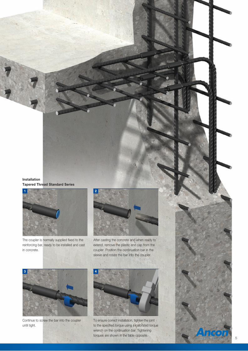
InstallationTapered Thread Standard Series
Continue to screw the bar into the coupler until tight.
After casting the concrete and when ready to extend, remove the plastic end cap from the coupler. Position the continuation bar in the sleeve and rotate the bar into the coupler.
The coupler is normally supplied fixed to the reinforcing bar, ready to be installed and cast in concrete.
To ensure correct installation, tighten the joint to the specified torque using a calibrated torque wrench on the continuation bar. Tightening torques are shown in the table opposite.
1
4
2
3
5
ls
le
Inlalm
lo
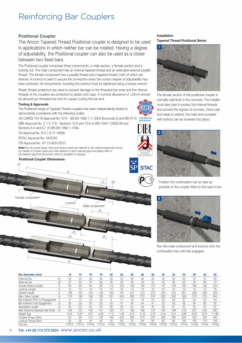
Positional CouplerThe Ancon Tapered Thread Positional coupler is designed to be used in applications in which neither bar can be rotated. Having a degree of adjustability, the Positional coupler can also be used as a closer between two fixed bars.The Positional coupler comprises three components, a male section, a female section and a locking nut. The male component has an internal tapered thread and an extended external parallel thread. The female component has a parallel thread and a tapered thread, both of which are internal. A locknut is used to secure the connection when the correct degree of adjustability has been achieved. All components, including the locknut must be tightened using a torque wrench.
Plastic thread protectors are used to prevent damage to the threaded bar ends and the internal threads of the couplers are protected by plastic end caps. A nominal allowance of +25mm should be allowed per threaded bar end for square cutting the bar end.
Testing & ApprovalsThe Positional range of Tapered Thread couplers has been independently tested to demonstrate compliance with the following codes:UK CARES TA1-B Approval No 1515 - BS EN 1992-1-1: 2004 (Eurocode 2) and BS 8110DIBt Approval No. Z-1.5-179 - Sections 12.6 and 12.8 of DIN 1045-1:2008-08 and Sections 8.4 and 8.7 of DIN EN 1992-1-1/NA.ÜA Approval No. R-2.1.9-17-15658SITAC Approval No. 0425/02ITB Approval No. AT-15-9037/2013Note:Not all coupler types, sizes and torque values are relevant to the national approvals shown. For details of coupler types and sizes relevant to each national approval please refer to the relevant approval document, which is available on request.
Reinforcing Bar Couplers
Position the continuation bar as near as possible to the coupler fitted to the cast-in bar.
Run the male component and locknut onto the continuation bar until fully engaged.
2
3
InstallationTapered Thread Positional Series
1
Bar Diameter (mm) 12 14 16 18 20 22 25 26 28 30 32 34 36 40 50External Dia. d1 25 25 30 36 36 42 48 46 50 55 55 60 70 70 85External Dia. d2 22 22 25 28 30 32 36 40 42 45 48 55 55 60 70Female Sleeve Length ls 84 89 95 95 112 120 132 136 137 147 153 164 190 190 233Locknut Length ln 13 13 13 13 13 13 13 13 13 15 15 15 15 15 16Closed Length lc 138 150 155 156 180 191 207 213 218 234 243 261 296 296 359Max. Open Length lo 178 190 196 195 231 245 266 273 274 295 305 328 373 374 454Bar Insertion Prior to Engagement li 9 12 15 18 8 11 16 18 22 25 28 31 34 40 54Bar Insertion Full Engagement le 26 29 32 32 33 37 42 44 47 50 53 56 58 66 82Adjustable Length la 23 23 24 25 26 28 34 34 34 36 37 42 54 52 67Max Distance between Bar Ends lm 126 124 132 131 165 171 182 185 174 195 199 216 257 242 290Weight (kg) 0.44 0.67 0.67 0.95 1.12 1.56 2.21 2.18 2.30 3.34 3.51 4.66 6.83 6.91 11.96Coupler Torque (Nm) 60 85 110 135 165 205 265 270 275 280 285 295 305 330 350Locknut Torque (Nm) 20 25 30 40 50 60 70 80 80 85 90 100 105 110 130Part No. TTP12 TTP14 TTP16 TTP18 TTP20 TTP22 TTP25 TTP26 TTP28 TTP30 TTP32 TTP34 TTP36 TTP40 TTP50
The female section of the positional coupler is normally cast flush in the concrete. The installer must take care to protect the internal threads and prevent the ingress of concrete. Once cast and ready to extend, the male end complete with locknut can be screwed into place.
lc
li d2
Female component
Male componentLocknut
Positional Coupler Dimensionsd1
6 Tel: +44 (0) 114 275 5224 www.ancon.co.uk
R-2.1.9-17-15658B AUCERT
S T E I E RMARK
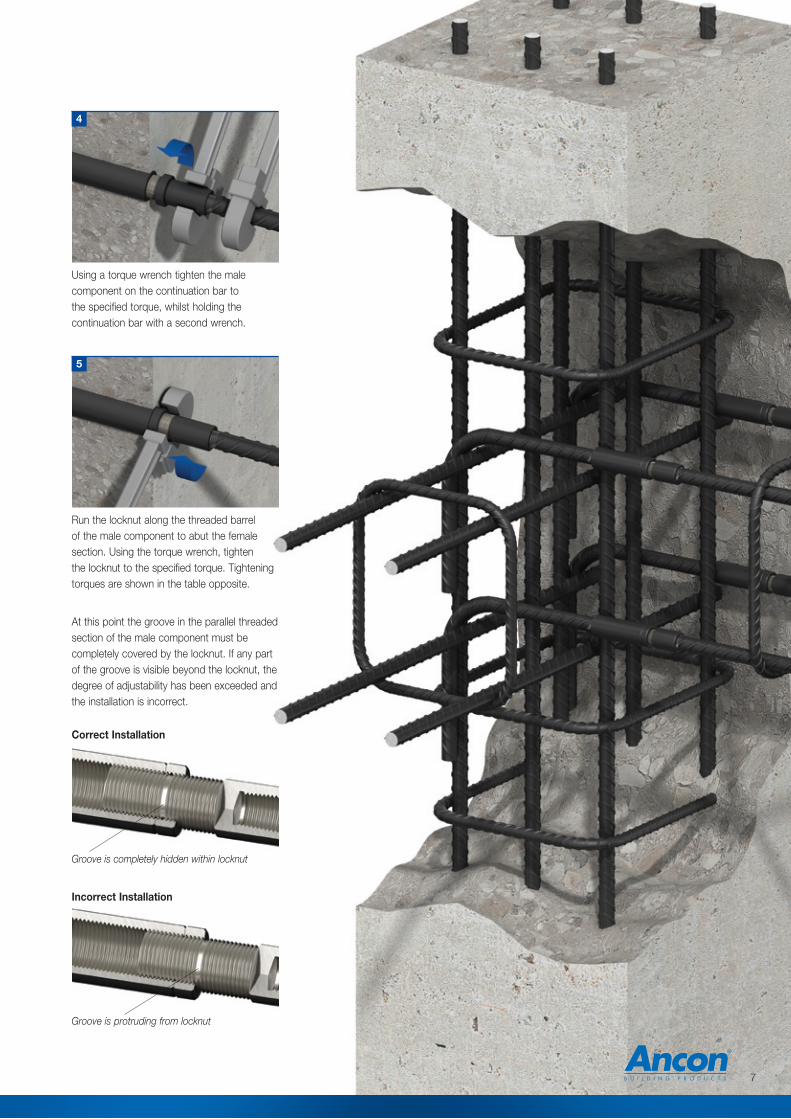
Run the locknut along the threaded barrel of the male component to abut the female section. Using the torque wrench, tighten the locknut to the specified torque. Tightening torques are shown in the table opposite.
At this point the groove in the parallel threaded section of the male component must be completely covered by the locknut. If any part of the groove is visible beyond the locknut, the degree of adjustability has been exceeded and the installation is incorrect.
Incorrect Installation
Groove is completely hidden within locknut
5
Using a torque wrench tighten the male component on the continuation bar to the specified torque, whilst holding the continuation bar with a second wrench.
4
Correct Installation
Groove is protruding from locknut
7
d
Reinforcing Bar Couplers
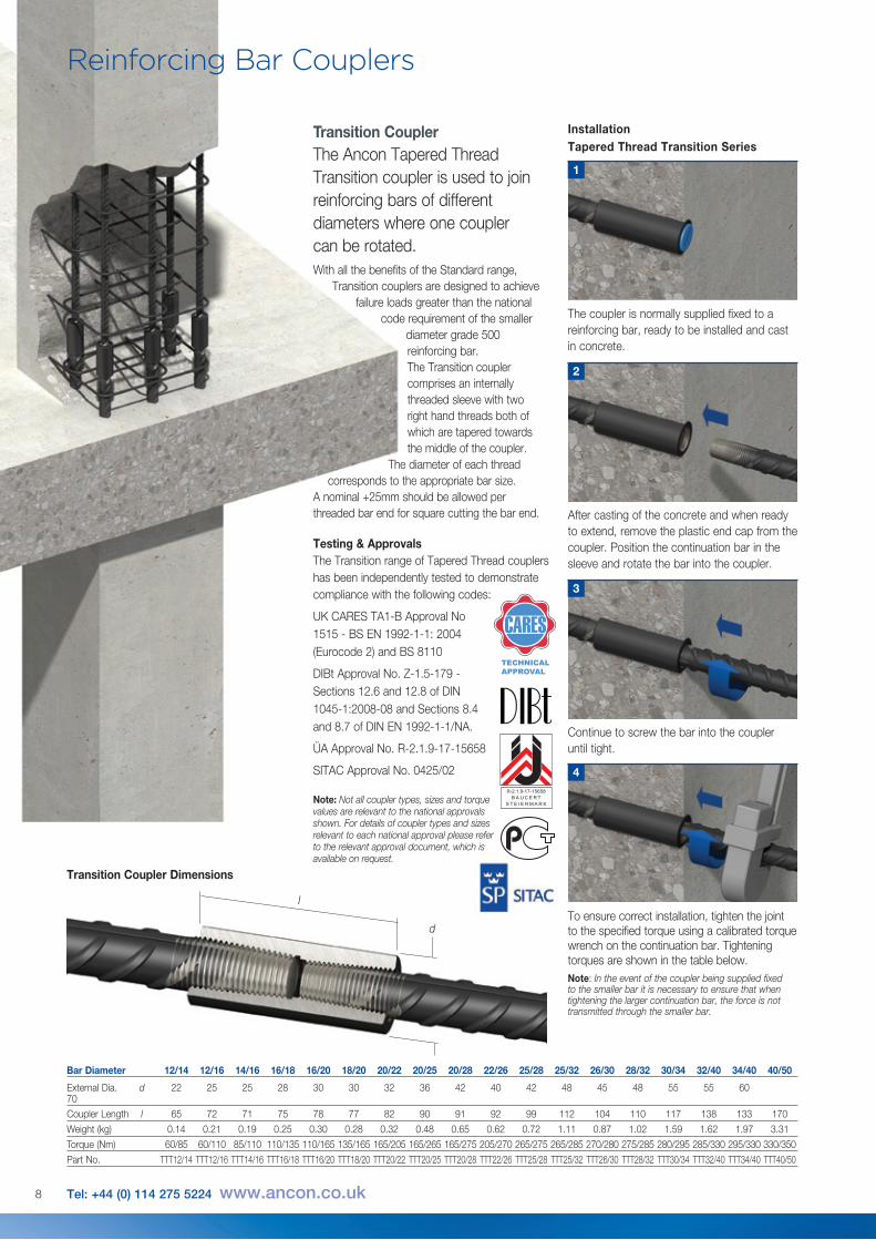
After casting of the concrete and when ready to extend, remove the plastic end cap from the coupler. Position the continuation bar in the sleeve and rotate the bar into the coupler.
2
Continue to screw the bar into the coupler until tight.
3
To ensure correct installation, tighten the joint to the specified torque using a calibrated torque wrench on the continuation bar. Tightening torques are shown in the table below. Note: In the event of the coupler being supplied fixed to the smaller bar it is necessary to ensure that when tightening the larger continuation bar, the force is not transmitted through the smaller bar.
4
1
The coupler is normally supplied fixed to a reinforcing bar, ready to be installed and cast in concrete.
Transition CouplerThe Ancon Tapered Thread Transition coupler is used to join reinforcing bars of different diameters where one coupler can be rotated.With all the benefits of the Standard range,
Transition couplers are designed to achieve failure loads greater than the national
code requirement of the smaller diameter grade 500 reinforcing bar.The Transition coupler comprises an internally threaded sleeve with two right hand threads both of which are tapered towards the middle of the coupler.
The diameter of each thread corresponds to the appropriate bar size.
A nominal +25mm should be allowed per threaded bar end for square cutting the bar end.
InstallationTapered Thread Transition Series
Testing & ApprovalsThe Transition range of Tapered Thread couplers has been independently tested to demonstrate compliance with the following codes:
UK CARES TA1-B Approval No 1515 - BS EN 1992-1-1: 2004 (Eurocode 2) and BS 8110
DIBt Approval No. Z-1.5-179 - Sections 12.6 and 12.8 of DIN 1045-1:2008-08 and Sections 8.4 and 8.7 of DIN EN 1992-1-1/NA.
ÜA Approval No. R-2.1.9-17-15658
SITAC Approval No. 0425/02
Note: Not all coupler types, sizes and torque values are relevant to the national approvals shown. For details of coupler types and sizes relevant to each national approval please refer to the relevant approval document, which is available on request.
d
l
Transition Coupler Dimensions
Bar Diameter 12/14 12/16 14/16 16/18 16/20 18/20 20/22 20/25 20/28 22/26 25/28 25/32 26/30 28/32 30/34 32/40 34/40 40/50
External Dia. d 22 25 25 28 30 30 32 36 42 40 42 48 45 48 55 55 60 70
Coupler Length l 65 72 71 75 78 77 82 90 91 92 99 112 104 110 117 138 133 170
Weight (kg) 0.14 0.21 0.19 0.25 0.30 0.28 0.32 0.48 0.65 0.62 0.72 1.11 0.87 1.02 1.59 1.62 1.97 3.31
Torque (Nm) 60/85 60/110 85/110 110/135 110/165 135/165 165/205 165/265 165/275 205/270 265/275 265/285 270/280 275/285 280/295 285/330 295/330 330/350
Part No. TTT12/14 TTT12/16 TTT14/16 TTT16/18 TTT16/20 TTT18/20 TTT20/22 TTT20/25 TTT20/28 TTT22/26 TTT25/28 TTT25/32 TTT26/30 TTT28/32 TTT30/34 TTT32/40 TTT34/40 TTT40/50
8 Tel: +44 (0) 114 275 5224 www.ancon.co.uk
R-2.1.9-17-15658B AUCERT
S T E I E RMARK
9
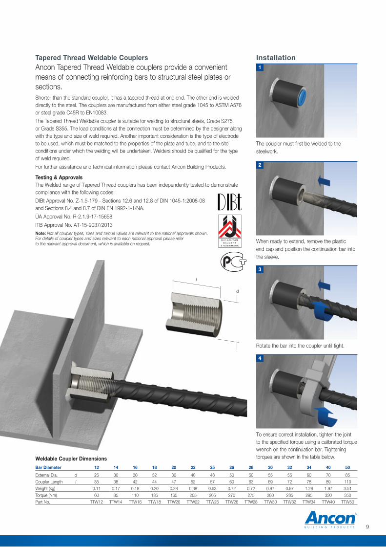
The coupler must first be welded to the steelwork.
1
Rotate the bar into the coupler until tight.
3
Installation
When ready to extend, remove the plastic end cap and position the continuation bar into the sleeve.
2
4
To ensure correct installation, tighten the joint to the specified torque using a calibrated torque wrench on the continuation bar. Tightening torques are shown in the table below.
Bar Diameter 12 14 16 18 20 22 25 26 28 30 32 34 40 50
External Dia. d 25 30 30 32 36 40 48 50 50 55 55 60 70 85
Coupler Length l 35 38 42 44 47 52 57 60 63 69 72 78 89 110
Weight (kg) 0.11 0.17 0.18 0.20 0.28 0.38 0.63 0.72 0.72 0.97 0.97 1.28 1.97 3.51
Torque (Nm) 60 85 110 135 165 205 265 270 275 280 285 295 330 350
Part No. TTW12 TTW14 TTW16 TTW18 TTW20 TTW22 TTW25 TTW26 TTW28 TTW30 TTW32 TTW34 TTW40 TTW50
Tapered Thread Weldable CouplersAncon Tapered Thread Weldable couplers provide a convenient means of connecting reinforcing bars to structural steel plates or sections.Shorter than the standard coupler, it has a tapered thread at one end. The other end is welded directly to the steel. The couplers are manufactured from either steel grade 1045 to ASTM A576 or steel grade C45R to EN10083.
The Tapered Thread Weldable coupler is suitable for welding to structural steels, Grade S275 or Grade S355. The load conditions at the connection must be determined by the designer along with the type and size of weld required. Another important consideration is the type of electrode to be used, which must be matched to the properties of the plate and tube, and to the site conditions under which the welding will be undertaken. Welders should be qualified for the type of weld required.
For further assistance and technical information please contact Ancon Building Products.
Testing & ApprovalsThe Welded range of Tapered Thread couplers has been independently tested to demonstrate compliance with the following codes:
DIBt Approval No. Z-1.5-179 - Sections 12.6 and 12.8 of DIN 1045-1:2008-08 and Sections 8.4 and 8.7 of DIN EN 1992-1-1/NA.
ÜA Approval No. R-2.1.9-17-15658
ITB Approval No. AT-15-9037/2013Note: Not all coupler types, sizes and torque values are relevant to the national approvals shown. For details of coupler types and sizes relevant to each national approval please refer to the relevant approval document, which is available on request.
d
l
Weldable Coupler Dimensions
R-2.1.9-17-15658B AUCERT
S T E I E RMARK
Reinforcing Bar Couplers
Torque Values (Nm)
Torque Wrenches for Couplers and Locknuts
Part No. E879008 E879009 E879010
Torque (Nm) 60 - 285 85 - 350 20 - 90
Torque Wrenches
Bar Diameter 12 14 16 18 20 22 24 25 26 28 30 32 34 36 40 50
Standard Coupler 60 85 110 135 165 205 250 265 270 275 280 285 295 305 330 350
Positional Coupler 60 85 110 135 165 205 250 265 270 275 280 285 295 305 330 350
Positional Locknut 20 25 30 40 50 60 65 70 80 80 85 90 100 105 110 130
Bar Diameter 12/14 12/16 14/16 16/18 16/20 18/20 20/22 20/25 20/28 22/26 25/28 25/32 26/30 28/32 30/34 32/40 34/40 40/50
Transition Coupler 60/85 60/110 85/110 110/135 110/165 135/165 165/205 165/265 165/275 205/270 265/275 265/285 270/280 275/285 280/295 285/330 295/330 330/350
Bar Diameter 12 14 16 18 20 22 24 25 26 28 30 32 34 36 40
External Dia. d 40 45 50 55 65 70 80 80 85 90 100 110 115 120 135
External Dia. d1 - - - - - - - - - 78 78 78 78 78 78
Coupler Length l 27.0 30.0 33.0 35.0 35.0 38.5 42.5 43.5 45.0 46.5 50.0 53.5 56.0 60.5 67.5
Coupler Length l1 - - - - - - - - - 21.5 25.0 28.5 30.0 35.5 42.5
Weight (kg) 0.25 0.34 0.46 0.61 0.83 1.06 1.54 1.57 1.84 1.86 2.23 2.81 3.11 3.62 5.17
Torque (Nm) 60 85 110 135 165 205 250 265 270 275 280 285 295 305 330
Part No. TTH12 TTH14 TTH16 TTH18 TTH20 TTH22 TTH24 TTH25 TTH26 TTH28 TTH30 TTH32 TTH34 TTH36 TTH40
Note: Where tapered thread headed anchors are used, the compressive strength of the concrete shall not be less than strength grade C32/40 (cylinder/cube).
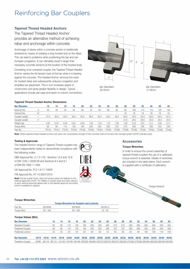
Tapered Thread Headed AnchorsThe Tapered Thread Headed Anchor provides an alternative method of achieving rebar end anchorage within concrete.Anchorage of rebars within a concrete section is traditionally achieved by means of creating a long hooked end on the rebar. This can lead to problems when positioning the bar and can increase congestion. It can ultimately result in larger than necessary concrete sections at the location of the hooked ends.
Consisting of an oversized coupler, the Tapered Thread Headed Anchor carries the full tension load of the bar when it is bearing against the concrete. The Headed Anchor removes the need for hooked rebar and subsequently reduces congestion and simplifies bar placement. This in turn increases speed of construction and gives greater flexibility in design. Typical applications include pile caps and beam to column connections.
Tapered Thread Headed Anchor Dimensions
d dd1
l
l1
l
Torque Wrench
Testing & ApprovalsThe Headed Anchor range of Tapered Thread couplers has been independently tested to demonstrate compliance with the following codes:
DIBt Approval No. Z-1.5-179 - Sections 12.6 and 12.8 of DIN 1045-1:2008-08 and Sections 8.4 and 8.7 of DIN EN 1992-1-1/NA.
ÜA Approval No. R-2.1.9-17-15658
ITB Approval No. AT-15-9037/2013Note: Not all coupler types, sizes and torque values are relevant to the national approvals shown. For details of coupler types and sizes relevant to each national approval please refer to the relevant approval document, which is available on request.
10 Tel: +44 (0) 114 275 5224 www.ancon.co.uk
AccessoriesTorque Wrenches
In order to ensure the correct assembly of tapered thread couplers the use of a calibrated torque wrench is essential. Details of wrenches are included in the table below. Each wrench is supplied with a certificate of calibration.
R-2.1.9-17-15658B AUCERT
S T E I E RMARK
Bar Diameters 28-40mm
Bar Diameters 12-26mm
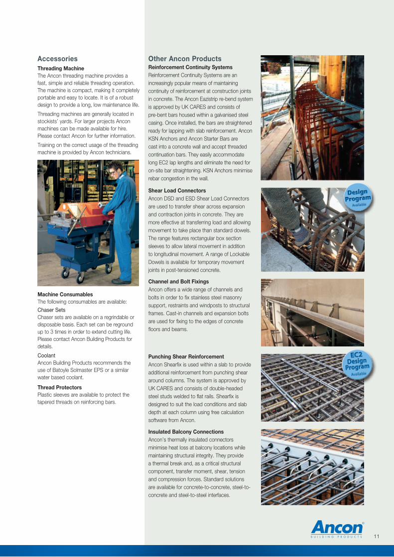
AccessoriesThreading MachineThe Ancon threading machine provides a fast, simple and reliable threading operation. The machine is compact, making it completely portable and easy to locate. It is of a robust design to provide a long, low maintenance life.
Threading machines are generally located in stockists’ yards. For larger projects Ancon machines can be made available for hire. Please contact Ancon for further information.
Training on the correct usage of the threading machine is provided by Ancon technicians.
11
Other Ancon ProductsReinforcement Continuity SystemsReinforcement Continuity Systems are an increasingly popular means of maintaining continuity of reinforcement at construction joints in concrete. The Ancon Eazistrip re-bend system is approved by UK CARES and consists of pre-bent bars housed within a galvanised steel casing. Once installed, the bars are straightened ready for lapping with slab reinforcement. Ancon KSN Anchors and Ancon Starter Bars are cast into a concrete wall and accept threaded continuation bars. They easily accommodate long EC2 lap lengths and eliminate the need for on-site bar straightening. KSN Anchors minimise rebar congestion in the wall.
Shear Load ConnectorsAncon DSD and ESD Shear Load Connectors are used to transfer shear across expansion and contraction joints in concrete. They are more effective at transferring load and allowing movement to take place than standard dowels. The range features rectangular box section sleeves to allow lateral movement in addition to longitudinal movement. A range of Lockable Dowels is available for temporary movement joints in post-tensioned concrete.
Channel and Bolt FixingsAncon offers a wide range of channels and bolts in order to fix stainless steel masonry support, restraints and windposts to structural frames. Cast-in channels and expansion bolts are used for fixing to the edges of concrete floors and beams.
Punching Shear ReinforcementAncon Shearfix is used within a slab to provide additional reinforcement from punching shear around columns. The system is approved by UK CARES and consists of double-headed steel studs welded to flat rails. Shearfix is designed to suit the load conditions and slab depth at each column using free calculation software from Ancon.
Insulated Balcony ConnectionsAncon’s thermally insulated connectors minimise heat loss at balcony locations while maintaining structural integrity. They provide a thermal break and, as a critical structural component, transfer moment, shear, tension and compression forces. Standard solutions are available for concrete-to-concrete, steel-to-concrete and steel-to-steel interfaces.
Machine ConsumablesThe following consumables are available:Chaser SetsChaser sets are available on a regrindable or disposable basis. Each set can be reground up to 3 times in order to extend cutting life. Please contact Ancon Building Products for details.
CoolantAncon Building Products recommends the use of Batoyle Solmaster EPS or a similar water based coolant.
Thread ProtectorsPlastic sleeves are available to protect the tapered threads on reinforcing bars.
The construction applications and details provided in this literature are indicative only. In every case, project working details should be entrusted to appropriately qualified and experienced persons.
Whilst every care has been exercised in the preparation of this document to ensure that any advice, recommendations or information is accurate, no liability or responsibility of any kind is accepted in respect of Ancon Building Products.
With a policy of continuous product development Ancon Building Products reserves the right to modify product design and specification without due notice.
© Ancon Building Products
These products are available from:
Masonry Support Systems
Lintels
Masonry Reinforcement
Windposts and Parapet Posts
Wall Ties and Restraint Fixings
Channel and Bolt Fixings
Tension and Compression Systems
Insulated Balcony Connectors
Shear Load Connectors
Punching Shear Reinforcement
Reinforcing Bar Couplers
Reinforcement Continuity Systems
Stainless Steel Fabrications
Flooring and Formed Sections
Refractory Fixings
This literature is printedon 80% recycled paper
80%
Ancon Building Products 98 Kurrajong Avenue Mount Druitt Sydney NSW 2770 Australia Tel: +61 (0) 2 8808 3100 Fax: +61 (0) 2 9675 3390 Email: [email protected] Visit: www.ancon.com.au
Ancon Building Products 2/19 Nuttall DriveHillsboroughChristchurch 8022New ZealandTel: +64 (0) 3 376 5205Fax: +64 (0) 3 376 5206Email: [email protected] Visit: www.ancon.co.nz
Ancon (Schweiz) AG Gewerbezone Widalmi 10 3216 Ried bei Kerzers Switzerland Tel: +41 (0) 31 750 3030 Fax: +41 (0) 31 750 3033 Email: [email protected] Visit: www.ancon.ch
Ancon Building Products GesmbH Puchgasse 1A-1220 ViennaAustria Tel: +43 (0) 1 259 58 62-0 Fax: +43 (0) 1 259 58 62-40 Email: [email protected] Visit: www.ancon.at
Ancon GmbH Bartholomäusstrasse 26 90489 Nuremberg Germany Tel: +49 (0) 911 955 1234 0 Fax: +49 (0) 911 955 1234 9 Email: [email protected] Visit: www.anconbp.de
Ancon Building Products President Way, President Park Sheffield S4 7UR United Kingdom Tel: +44 (0) 114 275 5224 Fax: +44 (0) 114 276 8543 Email: [email protected] Visit: www.ancon.co.uk Follow on Twitter: @AnconUK
Ancon (Middle East) FZE PO Box 17225 Jebel Ali Dubai United Arab Emirates Tel: +971 (0) 4 883 4346 Fax: +971 (0) 4 883 4347 Email: [email protected] Visit: www.ancon.ae