gaugeable tube fittings and adapter fittings (ms …...gaugeable tube fittings and adapter fittings...
TRANSCRIPT

Gaugeable Tube Fittings and Adapter Fittings 1 TUBE
FITTINGS
Gaugeable Tube Fi t t ings and Adapter F i t t ings
■ Available in tube sizes from 1/16 to 2 in. and 2 to 50 mm
■ Consistent gaugeability upon initial installation
■ Easy to disconnect and retighten
■ Wide variety of materials and configurations
■ Demonstrated reliability and performance
www.swagelok.com
2 Tube FittingsTU
BE
FITTI
NGS Features
■Live-loaded, two-ferrule design.
■Easy to install.
■No torque is transmitted to tubing during installation.
■Swagelok® gap inspection gauge ensures sufficient pull-up upon initial installation.
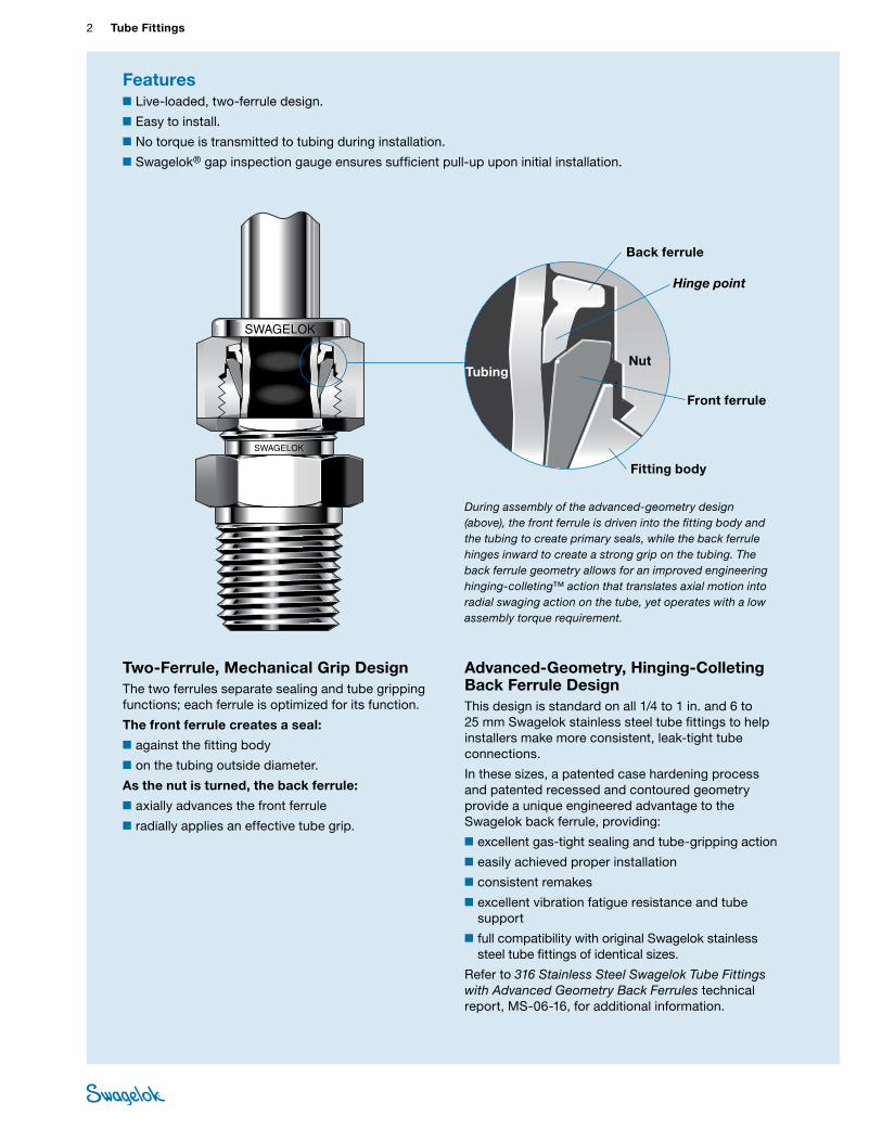
Two-Ferrule, Mechanical Grip DesignThe two ferrules separate sealing and tube gripping functions; each ferrule is optimized for its function.
The front ferrule creates a seal:
■against the fitting body
■on the tubing outside diameter.
As the nut is turned, the back ferrule:
■ axially advances the front ferrule
■radially applies an effective tube grip.
Advanced-Geometry, Hinging-Colleting Back Ferrule DesignThis design is standard on all 1/4 to 1 in. and 6 to 25 mm Swagelok stainless steel tube fittings to help installers make more consistent, leak-tight tube connections.
In these sizes, a patented case hardening process and patented recessed and contoured geometry provide a unique engineered advantage to the Swagelok back ferrule, providing:
■excellent gas-tight sealing and tube-gripping action
■easily achieved proper installation
■consistent remakes
■excellent vibration fatigue resistance and tube support
■full compatibility with original Swagelok stainless steel tube fittings of identical sizes.
Refer to 316 Stainless Steel Swagelok Tube Fittings with Advanced Geometry Back Ferrules technical report, MS-06-16, for additional information.
Front ferrule
Back ferrule
TubingNut
Fitting body
During assembly of the advanced-geometry design (above), the front ferrule is driven into the fitting body and the tubing to create primary seals, while the back ferrule hinges inward to create a strong grip on the tubing. The back ferrule geometry allows for an improved engineering hinging-colleting™ action that translates axial motion into radial swaging action on the tube, yet operates with a low assembly torque requirement.
Hinge point
Gaugeable Tube Fittings and Adapter Fittings 3 TUBE
FITTINGSStraight Fittings
Unions
Union, 14
Reducing Union, 15
Bulkhead Union and Bulkhead Reducing Union, 16
Male Connectors
NPT, 17
ISO/BSP Tapered Thread (RT), 18
ISO/BSP Parallel Thread (RS), 19
ISO/BSP Parallel Thread (RP), 20
Bulkhead NPT, 21
SAE/MS Straight Thread (ST) and Long SAE/MS Straight Thread (ST), 21
O-Seal (SAE/MS Straight Thread and NPT), 22
AN and AN Bulkhead Fitting, 23
10-32 Thread, M5 × 0.8 Thread, and Metric Thread (RS), 24
Features, 2
The Swagelok Tube Fitting Advantage, 6
Compliance with Industry Standards, 7
Materials, 8
O-Rings, 8
Cleaning and Packaging, 8
Metric Swagelok Tube Fittings, 9
Pressure Rating Basis and Thread Specifications, 9
Pressure Ratings, 10
Ordering Numbers and Dimensions, 14
Weld Connectors
Tube Socket, 24
Male Pipe, 25
Female Connectors
NPT, 26
ISO/BSP Tapered Thread (RT), ISO/BSP Parallel Thread (RJ and RP), 27
ISO/BSP Parallel Thread (RG, Gauge), 28
Bulkhead NPT, 28
Reducers
Reducer, 29
Long Reducer, 30
Bulkhead Reducer, 30
Port Connectors
Port Connector and Reducing Port Connector, 31
Contents
Additional Products■For Alloy 2507 super duplex
tube fittings, refer to Gaugeable Alloy 2507 Super Duplex Tube Fittings catalog, MS-01-174.
■For alloy 400 tube fittings, refer to Gaugeable Alloy 400/R-405 Mechanically Attached Pipe and Tube Fittings catalog, MS-02-332.
■For PFA tube fittings, refer to PFA Tube Fittings catalog, MS-01-05.
■For medium- and high-pressure tube fittings, refer to Medium- and High-Pressure Fittings, Tubing, Valves, and Accessories catalog, MS-02-472.
4 Tube FittingsTU
BE
FITTI
NGS
45° Elbows
Male
NPT, 39
Positionable, SAE/MS Straight Thread (ST), 39
Tees
Unions
Union and Reducing Union, 40
Male
Branch, NPT (TTM) and Adapter Tees, 42
Run, NPT (TMT), 43
Positionable Branch, SAE/MS Straight Thread (TTS) and Positionable Branch, ISO/BSP Parallel Thread (TTR), 44
Positionable Run, SAE/MS Straight Thread (TST), 44
Positionable Run, ISO/BSP Parallel Thread (TRT), 45
Female
Run, NPT (TFT), 45
Branch, NPT (TTF), 46
Caps and Plugs
Cap, 32
Plug, 32
Vent Protectors
Mud Dauber, 32
90° Elbows
Unions
Union, 33
Male
NPT, 34
ISO/BSP Tapered Thread (RT), 35
Reducing Elbow, 36
Positionable, ISO/BSP Parallel Thread (PR) and Positionable, SAE/MS Straight Thread (ST), 37
Weld
Tube Socket, 38
Male Pipe, 38
Female
NPT, 38
Cross
Union, 46
Application-Specific Fittings
Kwik-Clamp Flange to Swagelok Tube Fitting, 47
Orifice Plate Fitting, 48
Bored-Through FittingsFor thermocouples, dip tubes, and heat exchanger tees, 20
Tube AdaptersTube Adapter Information, 49
Male
NPT and ISO/BSP Tapered Thread (RT), 50
ISO/BSP Parallel Thread (RS and RP), 51
SAE/MS Straight Thread (ST) and O-Seal (SAE/MS Straight Thread), 52
AN Thread, 52
Pipe Weld, 53
Contents
Gaugeable Tube Fittings and Adapter Fittings 5 TUBE
FITTINGSFemale
NPT and ISO/BSP Tapered Thread (RT), 53
ISO/BSP Parallel Thread (RP and RJ), and ISO/BSP Parallel Thread (RG, Gauge), 54
AN Thread, 54
Additional Ordering Information, 55
Replacement Parts
Nuts
Female, 57
Knurled Female, 57
Male, 57
Ferrules
Front, 58
Back, 58
Nut-Ferrule Set and Package and Ferrule Set and Ferrule-Pak™ Package, 59
ISO/BSP Parallel Gaskets
Steel (RS Fitting), Copper (RP Fitting), Copper (RG, Gauge Fitting), and PTFE (RJ Fitting), 60
O-RingsBuna N (O-Seal Straight Threads and O-Seal Pipe Threads) and Fluorocarbon FKM (ISO/BSP Parallel Threads and SAE/MS Straight Threads), 61
Tools and AccessoriesHydraulic Swaging Units, 62
Preswaging Tools, 64
Wrenches, 65
Gap Inspection Gauges and Depth Marking Tools, 66
Bulkhead Retainers, 67
Inserts for Soft Plastic Tubing, 67
For liquid leak detectors, lubricants, and sealants, refer to Leak Detectors, Lubricants, and Sealants catalog, MS-01-91.
For tube benders and tube preparation tools, refer to Tubing Tools and Accessories catalog, MS-01-179.
Gaugeability, 68
Installation Instructions, 68
Swagelok Tube Fittings, 69
O-Seal Male Connectors, 69
Caps and Plugs, 70
Port Connectors, 70
Positionable Elbows and Tees, 71
Tube Adapters, 71
AN Thread Swivel Nut, 71
Weld Fittings, 72
Depth Marking Tool, 72
Preswaging Tool, 72
Chromatograph FittingsRefer to Gaugeable Chromatograph and Column End Fittings catalog, MS-02-173.
Dielectric FittingsRefer to Dielectric Fittings catalog, MS-02-36-SCS.
FlangesFor ANSI, DIN, and JIS flanges, refer to Flange Adapters catalog, MS-02-200.
VCO® and VCR® Face Seal Fittings
Refer to VCR Metal Gasket Face Seal Fittings catalog, MS-01-24 and VCO O-Rings Face Seal Fittings catalog MS-01-28.
Contents

6 Tube FittingsTU
BE
FITTI
NGS
Messages from customers credit Swagelok components and tube fittings, along with Swagelok distributor support, as having played a major role in helping them succeed.
Swagelok continues to improve the performance and reliability of the tube fitting for use in thousands of diverse applications—including research, alternative fuels, analytical and process instrumentation, oil and gas, power, petrochemical, and semiconductor industries—and addressing such critical issues as:
■gas-tight seal
■vibration (tube grip)
■thermal shock
■compliance with industry standards
■ installation
■corrosion
■ intermix/interchange.
Gas-tight SealExcellent sealing and consistent reassembly help ensure accurate measurements of process parameters—air, steam, fuel, and water—to keep your plant operating efficiently. Moreover, Swagelok tube fittings minimize fugitive emissions, as well as process fluid leakage and operation costs.
Contact your authorized Swagelok sales and service representative for more information about Swagelok Energy Emissions Surveys or to schedule a survey.
Vibration (Tube Grip) The patented case-hardening process and back-ferrule geometry provide excellent vibration fatigue resistance and tube support—even in harsh or stressful environments, such as hydrocarbon processing, on-vehicle applications, or rotary equipment applications.
Swagelok has conducted vibration tests, which show that the Swagelok tube fitting with advanced geometry hinging-colleting back ferrule isolates and protects the stress riser that is generated along the tube during the gripping part of assembly. The colleting portion of the back ferrule allows more material to contact the tube, for additional support. This colleting action enhances gripping performance and provides both direct and axial support to the gripping function. This design
minimizes the effects of bending deflection at the point of grip on the tubing.
Contact your authorized Swagelok representative for more information about vibration test reports.
The Swagelok Tube Fitting Advantage
“Over 10 000 fittings and not a single leak.”
“Used exclusively on our equipment and has proven to be very reliable and easy to maintain.”
“I have used Swagelok fittings from when I was a technician through today in my role in facility management. Would recommend them for any use.”
Gaugeable Tube Fittings and Adapter Fittings 7 TUBE
FITTINGS
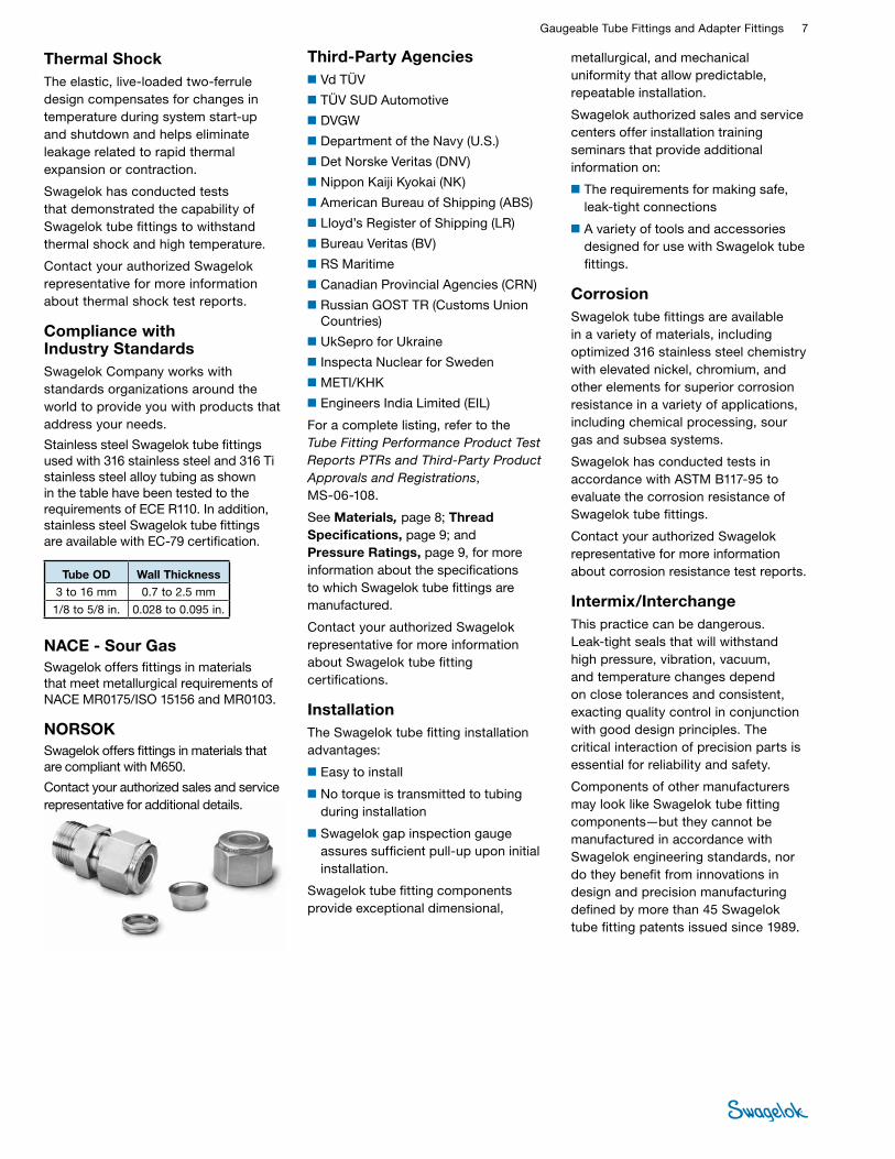
metallurgical, and mechanical uniformity that allow predictable, repeatable installation.
Swagelok authorized sales and service centers offer installation training seminars that provide additional information on:
■The requirements for making safe, leak-tight connections
■A variety of tools and accessories designed for use with Swagelok tube fittings.
CorrosionSwagelok tube fittings are available in a variety of materials, including optimized 316 stainless steel chemistry with elevated nickel, chromium, and other elements for superior corrosion resistance in a variety of applications, including chemical processing, sour gas and subsea systems.
Swagelok has conducted tests in accordance with ASTM B117-95 to evaluate the corrosion resistance of Swagelok tube fittings.
Contact your authorized Swagelok representative for more information about corrosion resistance test reports.
Intermix/InterchangeThis practice can be dangerous. Leak-tight seals that will withstand high pressure, vibration, vacuum, and temperature changes depend on close tolerances and consistent, exacting quality control in conjunction with good design principles. The critical interaction of precision parts is essential for reliability and safety.
Components of other manufacturers may look like Swagelok tube fitting components—but they cannot be manufactured in accordance with Swagelok engineering standards, nor do they benefit from innovations in design and precision manufacturing defined by more than 45 Swagelok tube fitting patents issued since 1989.
Thermal ShockThe elastic, live-loaded two-ferrule design compensates for changes in temperature during system start-up and shutdown and helps eliminate leakage related to rapid thermal expansion or contraction.
Swagelok has conducted tests that demonstrated the capability of Swagelok tube fittings to withstand thermal shock and high temperature.
Contact your authorized Swagelok representative for more information about thermal shock test reports.
Compliance with Industry StandardsSwagelok Company works with standards organizations around the world to provide you with products that address your needs.
Stainless steel Swagelok tube fittings used with 316 stainless steel and 316 Ti stainless steel alloy tubing as shown in the table have been tested to the requirements of ECE R110. In addition, stainless steel Swagelok tube fittings are available with EC-79 certification.
NACE - Sour GasSwagelok offers fittings in materials that meet metallurgical requirements of NACE MR0175/ISO 15156 and MR0103.
NORSOKSwagelok offers fittings in materials that are compliant with M650.
Contact your authorized sales and service representative for additional details.
Third-Party Agencies■Vd TÜV
■TÜV SUD Automotive
■DVGW
■Department of the Navy (U.S.)
■Det Norske Veritas (DNV)
■Nippon Kaiji Kyokai (NK)
■American Bureau of Shipping (ABS)
■Lloyd’s Register of Shipping (LR)
■Bureau Veritas (BV)
■RS Maritime
■Canadian Provincial Agencies (CRN)
■Russian GOST TR (Customs Union Countries)
■UkSepro for Ukraine
■Inspecta Nuclear for Sweden
■METI/KHK
■Engineers India Limited (EIL)
For a complete listing, refer to the Tube Fitting Performance Product Test Reports PTRs and Third-Party Product Approvals and Registrations, MS-06-108.
See Materials, page 8; Thread Specifications, page 9; and Pressure Ratings, page 9, for more information about the specifications to which Swagelok tube fittings are manufactured.
Contact your authorized Swagelok representative for more information about Swagelok tube fitting certifications.
InstallationThe Swagelok tube fitting installation advantages:
■Easy to install
■No torque is transmitted to tubing during installation
■Swagelok gap inspection gauge assures sufficient pull-up upon initial installation.
Swagelok tube fitting components provide exceptional dimensional,
Tube OD Wall Thickness3 to 16 mm 0.7 to 2.5 mm
1/8 to 5/8 in. 0.028 to 0.095 in.
8 Tube FittingsTU
BE
FITTI
NGS
O-RingsO-seal fittings include a 70 durometer Buna N O-ring. Other straight-thread fittings with O-rings include a 90 durometer fluorocarbon FKM O-ring. Other O-ring materials are available upon request. O-rings are coated with a thin film of silicone-based lubricant. Removal of factory-applied lubricants may alter performance.
For ST and ST positionable fittings used in ECE-R110 applications, add the DE O-ring suffix to the ordering number. Example: SS-600-1-6STDE
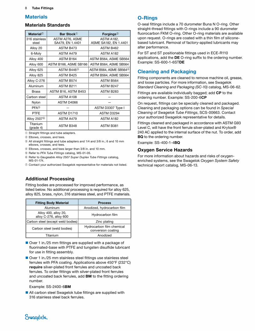
Materials
Cleaning and PackagingFitting components are cleaned to remove machine oil, grease, and loose particles. For more information, see Swagelok Standard Cleaning and Packaging (SC-10) catalog, MS-06-62.
Fittings are available individually bagged; add CP to the ordering number. Example: SS-200-6CP
On request, fittings can be specially cleaned and packaged. Cleaning and packaging options can be found in Special Cleaning of Swagelok Tube Fittings, SCS-00663. Contact your authorized Swagelok representative for details.
Fittings cleaned and packaged in accordance with ASTM G93 Level C, will have the front ferrule silver-plated and Krytox® 240 AC applied to the internal surface of the nut. To order, add BQ to the ordering number.
Example: SS-400-1-4BQ
Oxygen Service HazardsFor more information about hazards and risks of oxygen-enriched systems, see the Swagelok Oxygen System Safety technical report catalog, MS-06-13.
Materials Standards
➀Straight fittings and tube adapters.➁Elbows, crosses, and tees.➂ All straight fittings and tube adapters and 1/4 and 3/8 in.; 6 and 10 mm
elbows, crosses, and tees.➃ Elbows, crosses, and tees larger than 3/8 in. and 10 mm.➄ Refer to PFA Tube Fittings catalog, MS-01-05.➅ Refer to Gaugeable Alloy 2507 Super Duplex Tube Fittings catalog,
MS-01-174.➆ Contact your authorized Swagelok representative for materials not listed.
Material➆ Bar Stock➀ Forgings➁
316 stainless steel
ASTM A276, ASME SA479, EN 1.4401
ASTM A182, ASME SA182, EN 1.4401
Alloy 20 ASTM B473 ASTM B462
6-Moly ASTM A479 ASTM A182
Alloy 400 ASTM B164 ASTM B564, ASME SB564
Alloy 600 ASTM B166, ASME SB166 ASTM B564, ASME SB564
Alloy 625 ASTM B446➂ ASTM B564, ASME SB564➃
Alloy 825 ASTM B425 ASTM B564, ASME SB564
Alloy C-276 ASTM B574 ASTM B564
Aluminum ASTM B211 ASTM B247
Brass ASTM B16, ASTM B453 ASTM B283
Carbon steel ASTM A108 —
Nylon ASTM D4066 —
PFA➄ — ASTM D3307 Type I
PTFE ASTM D1710 ASTM D3294
Alloy 2507➅ ASTM A479 ASTM A182
Titanium (grade 4) ASTM B348 ASTM B381
Additional ProcessingFitting bodies are processed for improved performance, as listed below. No additional processing is required for alloy 625, alloy 825, brass, nylon, 316 stainless steel, and PTFE materials.
■Over 1 in./25 mm fittings are supplied with a package of fluorinated-base with PTFE and tungsten disulfide lubricant for use in fitting assembly.
■Over 1 in./25 mm stainless steel fittings use stainless steel ferrules with PFA coating. Applications above 450°F (232°C) require silver-plated front ferrules and uncoated back ferrules. To order fittings with silver-plated front ferrules and uncoated back ferrules, add BM to the fitting ordering number.
Example: SS-2400-6BM
■All carbon steel Swagelok tube fittings are supplied with 316 stainless steel back ferrules.
Fitting Body Material Process Aluminum Anodized, hydrocarbon film
Alloy 400, alloy 20, alloy C-276, alloy 600 Hydrocarbon film
Carbon steel (except weld bodies) Zinc plating
Carbon steel (weld bodies) Hydrocarbon film chemical conversion coating
Titanium Anodized
Gaugeable Tube Fittings and Adapter Fittings 9 TUBE
FITTINGS
Pressure Rating Basis and Thread Specifications
Thread Type (End Connection) Pressure Rating Basis Thread Type Reference Specification
Swagelok Tube Fittings
Swagelok tube fitting ends are rated to the working pressure of tubing as listed in Swagelok Tubing Data, MS-01-107. Careful selection of high-quality tubing is important when
installing safe, leak-tight systems.
Unified Inch Screw Threads ASME B1.1
NPT ASME B31.3, Process Piping or pressure testing with a 4:1 design factor based on hydraulic fluid. leakage. NPT ASME B1.20.1,
SAE AS71051
ISO/BSP (tapered) (Swagelok RT fittings)
ASME B31.3, Process Piping or pressure testing with a 4:1 design factor based on hydraulic fluid. leakage.
ISO/BSP (tapered)Swagelok RT fittings
ISO 7, BS EN 10226-1, JIS B0203
ISO/BSP (parallel) (Swagelok RS fittings)
ISO 1179-3, ISO 228-1 Threads with Light-Duty Stud Ends with Sealing by O-ring with Retaining Ring (types G and H) or pressure testing with a 4:1 design factor based on
hydraulic fluid leakage.
ISO/BSP (parallel)Swagelok RP and RS
fittings
ISO 228, J IS B0202
ISO/BSP (parallel) (Swagelok RP fittings)
ISO 1179-4, ISO 228-1 Threads with Stud Ends for general use only with metal-to-metal sealing (type B) or pressure testing with a 4:1 design factor based on hydraulic fluid leakage.
ISO/BSP (parallel)Swagelok RP and RS
fittings
ISO 228, JIS B0202
ISO/BSP (gauge)(Based on EN 837-1 and 837-3) (Swagelok RG and RJ fittings)
ASME B31.3, Process Piping or pressure testing with a 4:1 design factor based on hydraulic fluid. leakage.
ISO/BSP (parallel)Swagelok RG and RJ
fittings
ISO 228, JIS B0202
SAE–Light Duty(Swagelok ST fittings)
SAE J1926/3, Connections for General Use and Fluid Power-Ports and Stud Ends with ASME B1.1 Threads and O-ring Sealing-Part 3: Light-Duty (L-Series) Stud Ends or
pressure testing with a 4:1 design factor based on hydraulic fluid leakage.
Unified Inch Screw Threads
Swagelok ST fittingsASME B1.1
SAE–Heavy Duty(Swagelok STH fittings)
SAE J1926/2, Connections for General Use and Fluid Power-Ports and Stud Ends with ASME B1.1 Threads and O-ring Sealing-Part 2: Heavy-Duty (S-Series) or pressure testing with a 4:1 design factor based on hydraulic fluid
leakage.
Unified Inch Screw Threads Swagelok ST
fittingsASME B1.1
Swagelok AN fittings SAE J514, Hydraulic Tube Fittings or pressure testing with a 4:1 design factor based on hydraulic fluid leakage.
Unified Inch Screw Threads
Swagelok AN fittings
ASME B1.1 UNJ, SAE AS 8879
Pipe Thread SealantsA thread sealant should always be used when assembling tapered threads. SWAK™ anaerobic pipe thread sealant and Swagelok PTFE tape are available. Refer to Leak Detectors, Lubricants, and Sealants catalog, MS-01-91, for additional information.
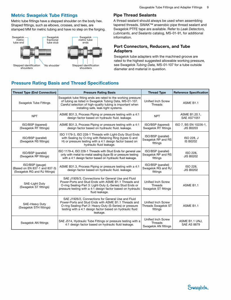
Metric Swagelok Tube FittingsMetric tube fittings have a stepped shoulder on the body hex. Shaped fittings, such as elbows, crosses, and tees, are stamped MM for metric tubing and have no step on the forging.
Swagelok metric
tube end
Swagelok fractional tube stub
No shoulderStepped identification shoulders
Stepped identification shoulders
Swagelok metric tube
ends
Port Connectors, Reducers, and Tube AdaptersSwagelok tube adapters with the machined groove are rated to the highest suggested allowable working pressure, see Swagelok Tubing Data, MS-01-107 for a tube outside diameter and material in question.
10 Tube FittingsTU
BE
FITTI
NGS
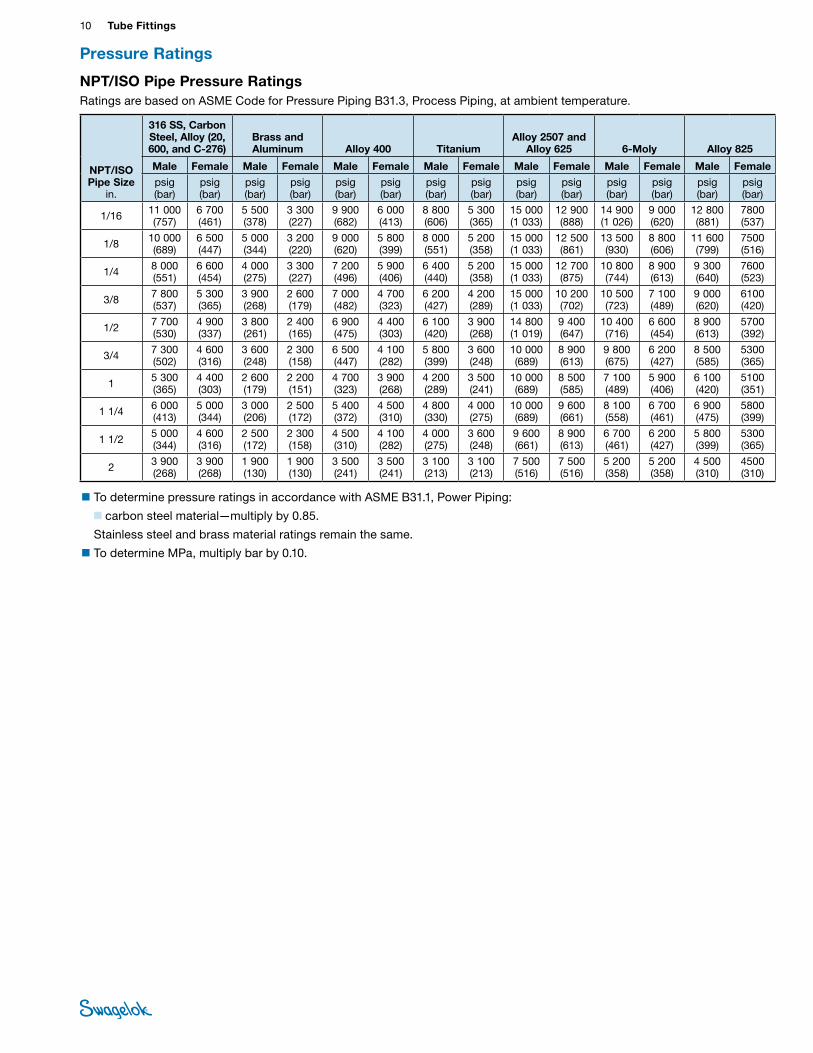
NPT/ISO Pipe Pressure RatingsRatings are based on ASME Code for Pressure Piping B31.3, Process Piping, at ambient temperature.
NPT/ISO Pipe Size
in.
316 SS, Carbon Steel, Alloy (20, 600, and C-276)
Brass and Aluminum Alloy 400 Titanium
Alloy 2507 and Alloy 625 6-Moly Alloy 825
Male Female Male Female Male Female Male Female Male Female Male Female Male Female
psig (bar)
psig (bar)
psig (bar)
psig (bar)
psig (bar)
psig (bar)
psig (bar)
psig (bar)
psig (bar)
psig (bar)
psig (bar)
psig (bar)
psig (bar)
psig (bar)
1/16 11 000 (757)
6 700 (461)
5 500 (378)
3 300 (227)
9 900 (682)
6 000 (413)
8 800 (606)
5 300 (365)
15 000 (1 033)
12 900 (888)
14 900 (1 026)
9 000 (620)
12 800 (881)
7800 (537)
1/8 10 000 (689)
6 500 (447)
5 000 (344)
3 200 (220)
9 000 (620)
5 800 (399)
8 000 (551)
5 200 (358)
15 000 (1 033)
12 500 (861)
13 500 (930)
8 800 (606)
11 600 (799)
7500 (516)
1/4 8 000 (551)
6 600 (454)
4 000 (275)
3 300 (227)
7 200 (496)
5 900 (406)
6 400 (440)
5 200 (358)
15 000 (1 033)
12 700 (875)
10 800 (744)
8 900 (613)
9 300 (640)
7600 (523)
3/8 7 800 (537)
5 300 (365)
3 900 (268)
2 600 (179)
7 000 (482)
4 700 (323)
6 200 (427)
4 200 (289)
15 000 (1 033)
10 200 (702)
10 500 (723)
7 100 (489)
9 000 (620)
6100 (420)
1/2 7 700 (530)
4 900 (337)
3 800 (261)
2 400 (165)
6 900 (475)
4 400 (303)
6 100 (420)
3 900 (268)
14 800 (1 019)
9 400 (647)
10 400 (716)
6 600 (454)
8 900 (613)
5700 (392)
3/4 7 300 (502)
4 600 (316)
3 600 (248)
2 300 (158)
6 500 (447)
4 100 (282)
5 800 (399)
3 600 (248)
10 000 (689)
8 900 (613)
9 800 (675)
6 200 (427)
8 500 (585)
5300 (365)
1 5 300 (365)
4 400 (303)
2 600 (179)
2 200 (151)
4 700 (323)
3 900 (268)
4 200 (289)
3 500 (241)
10 000 (689)
8 500 (585)
7 100 (489)
5 900 (406)
6 100 (420)
5100 (351)
1 1/4 6 000 (413)
5 000 (344)
3 000 (206)
2 500 (172)
5 400 (372)
4 500 (310)
4 800 (330)
4 000 (275)
10 000 (689)
9 600 (661)
8 100 (558)
6 700 (461)
6 900 (475)
5800 (399)
1 1/2 5 000 (344)
4 600 (316)
2 500 (172)
2 300 (158)
4 500 (310)
4 100 (282)
4 000 (275)
3 600 (248)
9 600 (661)
8 900 (613)
6 700 (461)
6 200 (427)
5 800 (399)
5300 (365)
2 3 900 (268)
3 900 (268)
1 900 (130)
1 900 (130)
3 500 (241)
3 500 (241)
3 100 (213)
3 100 (213)
7 500 (516)
7 500 (516)
5 200 (358)
5 200 (358)
4 500 (310)
4500 (310)
■To determine pressure ratings in accordance with ASME B31.1, Power Piping:
■ carbon steel material—multiply by 0.85.
Stainless steel and brass material ratings remain the same.
■To determine MPa, multiply bar by 0.10.
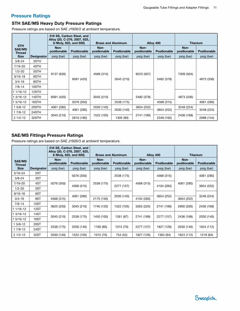
Pressure Ratings
Gaugeable Tube Fittings and Adapter Fittings 11 TUBE
FITTINGS
SAE/MS Fittings Pressure RatingsPressure ratings are based on SAE J1926/3 at ambient temperature.
SAE/MS Thread
Size Designator
316 SS, Carbon Steel, and Alloy (20, C-276, 2507, 625,
6-Moly, 825, and 600) Brass and Aluminum Alloy 400 Titanium
Non- positionable Positionable
Non- positionable Positionable
Non- positionable Positionable
Non- positionable Positionable
psig (bar) psig (bar) psig (bar) psig (bar) psig (bar) psig (bar) psig (bar) psig (bar)
5/16-24 2ST
5076 (350)
5076 (350)
2538 (175)
2538 (175)
4568 (315)
4568 (315)
4061 (280)
4061 (280) 3/8-24 3ST
7/16-20 4ST4568 (315) 2277 (157) 4104 (283) 3654 (252)
1/2-20 5ST
9/16-18 6ST4061 (280) 2030 (140) 3654 (252) 3248 (224)
3/4-16 8ST 4568 (315) 2175 (150) 4104 (283) 3654 (252)
7/8-14 10ST3625 (250) 3045 (210) 1740 (120) 1522 (105) 3263 (225) 2741 (189) 2900 (200) 2436 (168)
1 1/16-12 12ST
1 3/16-12 14ST3045 (210) 2538 (175) 1450 (100) 1261 (87) 2741 (189) 2277 (157) 2436 (168) 2030 (140)
1 5/16-12 16ST
1 5/8-12 20ST2538 (175) 2030 (140) 1160 (80) 1015 (70) 2277 (157) 1827 (126) 2030 (140) 1624 (112)
1 7/8-12 24ST
2 1/2-12 32ST 2030 (140) 1522 (105) 1015 (70) 754 (52) 1827 (126) 1363 (94) 1624 (112) 1218 (84)
STH SAE/MS Heavy Duty Pressure RatingsPressure ratings are based on SAE J1926/2 at ambient temperature.
STH SAE/MS Thread
Size Designator
316 SS, Carbon Steel, and Alloy (20, C-276, 2507, 625,
6-Moly, 825, and 600) Brass and Aluminum Alloy 400 Titanium
Non- positionable Positionable
Non- positionable Positionable
Non- positionable Positionable
Non- positionable Positionable
psig (bar) psig (bar) psig (bar) psig (bar) psig (bar) psig (bar) psig (bar) psig (bar)
3/8-24 3STH
9137 (630)
6091 (420)
4568 (315)
3045 (210)
8223 (567)
5482 (378)
7309 (504)
4873 (336)
7/16-20 4STH
1/2-20 5STH
9/16-18 6STH
3/4-16 8STH
7/8-14 10STH
1 1/16-12 12STH
6091 (420) 3045 (210) 5482 (378) 4873 (336)1 3/16-12 14STH
1 5/16-12 16STH 5076 (350) 2538 (175) 4568 (315) 4061 (280)
1 5/8-12 20STH 4061 (280)4061 (280)
2030 (140)2030 (140)
3654 (252)3654 (252)
3248 (224)3248 (224)
1 7/8-12 24STH3045 (210) 1522 (105) 2741 (189) 2436 (168)
2 1/2-12 32STH 2610 (180) 1305 (90) 2349 (162) 2088 (144)
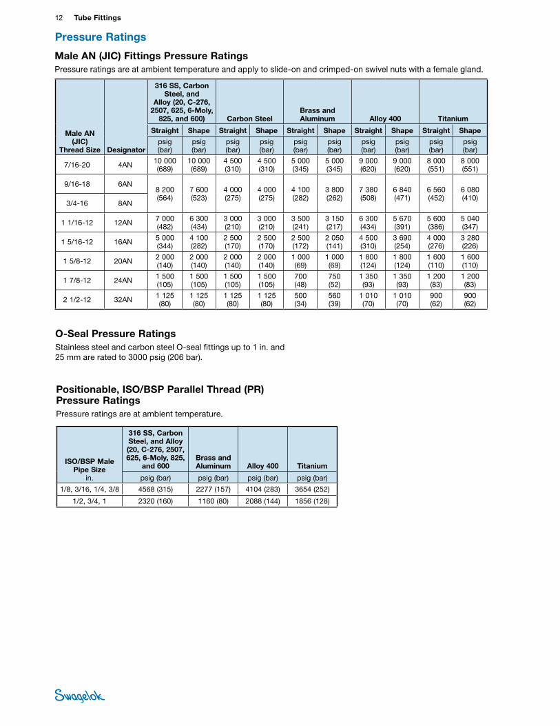
Pressure Ratings
12 Tube FittingsTU
BE
FITTI
NGS
O-Seal Pressure RatingsStainless steel and carbon steel O-seal fittings up to 1 in. and 25 mm are rated to 3000 psig (206 bar).
Male AN (JIC) Fittings Pressure RatingsPressure ratings are at ambient temperature and apply to slide-on and crimped-on swivel nuts with a female gland.
Male AN (JIC)
Thread Size Designator
316 SS, Carbon Steel, and
Alloy (20, C-276, 2507, 625, 6-Moly,
825, and 600) Carbon SteelBrass and Aluminum Alloy 400 Titanium
Straight Shape Straight Shape Straight Shape Straight Shape Straight Shape
psig (bar)
psig (bar)
psig (bar)
psig (bar)
psig (bar)
psig (bar)
psig (bar)
psig (bar)
psig (bar)
psig (bar)
7/16-20 4AN 10 000 (689)
10 000 (689)
4 500 (310)
4 500 (310)
5 000 (345)
5 000 (345)
9 000 (620)
9 000 (620)
8 000 (551)
8 000 (551)
9/16-18 6AN8 200 (564)
7 600 (523)
4 000 (275)
4 000 (275)
4 100 (282)
3 800 (262)
7 380 (508)
6 840 (471)
6 560 (452)
6 080 (410)
3/4-16 8AN
1 1/16-12 12AN 7 000 (482)
6 300 (434)
3 000 (210)
3 000 (210)
3 500 (241)
3 150 (217)
6 300 (434)
5 670 (391)
5 600 (386)
5 040 (347)
1 5/16-12 16AN 5 000 (344)
4 100 (282)
2 500 (170)
2 500 (170)
2 500 (172)
2 050 (141)
4 500 (310)
3 690 (254)
4 000 (276)
3 280 (226)
1 5/8-12 20AN 2 000 (140)
2 000 (140)
2 000 (140)
2 000 (140)
1 000 (69)
1 000 (69)
1 800 (124)
1 800 (124)
1 600 (110)
1 600 (110)
1 7/8-12 24AN 1 500 (105)
1 500 (105)
1 500 (105)
1 500 (105)
700 (48)
750 (52)
1 350 (93)
1 350 (93)
1 200 (83)
1 200 (83)
2 1/2-12 32AN 1 125 (80)
1 125 (80)
1 125 (80)
1 125 (80)
500 (34)
560 (39)
1 010 (70)
1 010 (70)
900 (62)
900 (62)
Positionable, ISO/BSP Parallel Thread (PR) Pressure RatingsPressure ratings are at ambient temperature.
ISO/BSP Male Pipe Size
in.
316 SS, Carbon Steel, and Alloy (20, C-276, 2507, 625, 6-Moly, 825,
and 600Brass and Aluminum Alloy 400 Titanium
psig (bar) psig (bar) psig (bar) psig (bar)
1/8, 3/16, 1/4, 3/8 4568 (315) 2277 (157) 4104 (283) 3654 (252)
1/2, 3/4, 1 2320 (160) 1160 (80) 2088 (144) 1856 (128)
Pressure Ratings
Gaugeable Tube Fittings and Adapter Fittings 13 TUBE
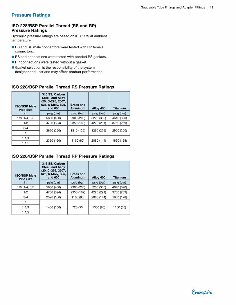
FITTINGSISO 228/BSP Parallel Thread (RS and RP) Pressure RatingsHydraulic pressure ratings are based on ISO 1179 at ambient temperature.
■RS and RP male connectors were tested with RP female connectors.
■RS end connections were tested with bonded RS gaskets.
■RP connections were tested without a gasket.
■Gasket selection is the responsibility of the system designer and user and may affect product performance.
Pressure Ratings
ISO/BSP Male Pipe Size
in.
316 SS, Carbon Steel, and Alloy (20, C-276, 2507, 625, 6-Moly, 825,
and 600Brass and Aluminum Alloy 400 Titanium
psig (bar) psig (bar) psig (bar) psig (bar)
1/8, 1/4, 3/8 5800 (400) 2900 (200) 5220 (360) 4640 (320)
1/2 4700 (324) 2350 (162) 4220 (291) 3750 (259)
3/43620 (250) 1810 (125) 3260 (225) 2900 (200)
1
1 1/42320 (160) 1160 (80) 2080 (144) 1850 (128)
1 1/2
ISO/BSP Male Pipe Size
in.
316 SS, Carbon Steel, and Alloy (20, C-276, 2507, 625, 6-Moly, 825,
and 600Brass and Aluminum Alloy 400 Titanium
psig (bar) psig (bar) psig (bar) psig (bar)
1/8, 1/4, 3/8 5800 (400) 2900 (200) 5200 (360) 4640 (320)
1/2 4700 (324) 2350 (162) 4220 (291) 3750 (259)
3/4 2320 (160) 1160 (80) 2080 (144) 1850 (128)
1
1450 (100) 720 (50) 1300 (90) 1160 (80)1 1/4
1 1/2
ISO 228/BSP Parallel Thread RS Pressure Ratings
ISO 228/BSP Parallel Thread RP Pressure Ratings
14 Tube FittingsTU
BE
FITTI
NGS
Tube OD
Basic Ordering Number
Dimensions
A D E
Dimensions, in. 1/16 -100-6 0.99 0.34 0.05
1/8 -200-6 1.40 0.50 0.09
3/16 -300-6 1.47 0.54 0.12
1/4 -400-6 1.61 0.60 0.19
5/16 -500-6 1.69 0.64 0.25
3/8 -600-6 1.77 0.66 0.28
1/2 -810-6 2.02 0.90 0.41
1/2 -810-6-0030➀ 4.30 —0.50
5/8 -1010-6 2.05 0.96
3/4 -1210-6 2.11 0.62
7/8 -1410-6 2.17 1.02 0.72
1 -1610-6 2.55 1.23
0.88
1 1/8 B-1810-6 0.97
1 1/4 -2000-6 3.63 1.62 1.09
1 1/2 -2400-6 4.25 1.97 1.34
2 -3200-6 5.88 2.66 1.81
Dimensions, mm 2 -2M0-6 35.6
12.9 1.7
3 -3M0-6 35.3 2.4
4 -4M0-6 37.3 13.7
6 -6M0-6 41.0 15.3 4.8
8 -8M0-6 43.2 16.2 6.4
10 -10M0-6 46.2 17.2 7.9
12 -12M0-6 51.2 22.8 9.5
14 -14M0-6
52.0 24.4
11.1
15 -15M0-6 11.9
16 -16M0-6 12.7
18 -18M0-6 53.5 15.1
20 -20M0-6 55.0 26.0
15.9
22 -22M0-6 18.3
25 -25M0-6 65.0 31.3 21.8
28 -28M0-6 85.0 36.6
B-28M0-6 65.4 31.6 24.6
30 -30M0-6 92.7 39.6 26.2
32 -32M0-6 97.3 42.0 28.6
38 -38M0-6 114 49.4 33.7
50 -50M0-6 146 65.0 45.2
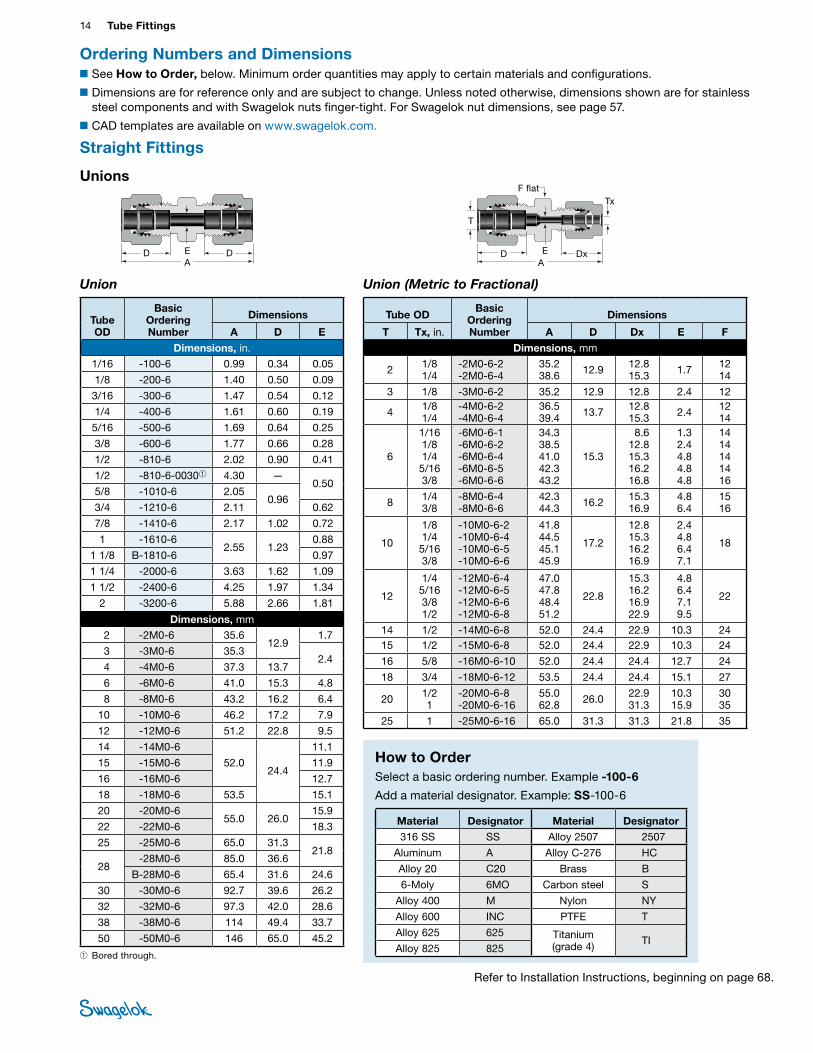
Union
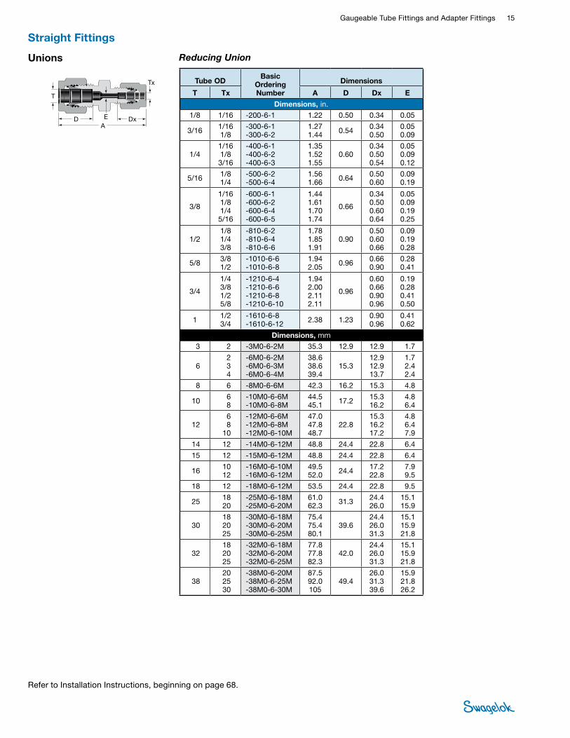
Ordering Numbers and Dimensions ■See How to Order, below. Minimum order quantities may apply to certain materials and configurations.
■Dimensions are for reference only and are subject to change. Unless noted otherwise, dimensions shown are for stainless steel components and with Swagelok nuts finger-tight. For Swagelok nut dimensions, see page 57.
■CAD templates are available on www.swagelok.com.
Straight Fittings
Unions
Union (Metric to Fractional)
D DAE D Dx
AE
F flatTx
T
➀ Bored through.
Tube ODBasic
Ordering Number
Dimensions
T Tx, in. A D Dx E F
Dimensions, mm
2 1/8 1/4
-2M0-6-2 -2M0-6-4
35.2 38.6 12.9 12.8
15.3 1.7 12 14
3 1/8 -3M0-6-2 35.2 12.9 12.8 2.4 12
4 1/8 1/4
-4M0-6-2 -4M0-6-4
36.5 39.4 13.7 12.8
15.3 2.4 12 14
6
1/16 1/8 1/4 5/16 3/8
-6M0-6-1 -6M0-6-2 -6M0-6-4 -6M0-6-5 -6M0-6-6
34.3 38.5 41.0 42.3 43.2
15.3
8.6 12.8 15.3 16.2 16.8
1.3 2.4 4.8 4.8 4.8
14 14 14 14 16
8 1/4 3/8
-8M0-6-4 -8M0-6-6
42.3 44.3 16.2 15.3
16.9 4.8 6.4
15 16
10
1/8 1/4 5/16 3/8
-10M0-6-2 -10M0-6-4 -10M0-6-5 -10M0-6-6
41.8 44.5 45.1 45.9
17.2
12.8 15.3 16.2 16.9
2.4 4.8 6.4 7.1
18
12
1/4 5/16 3/8 1/2
-12M0-6-4 -12M0-6-5 -12M0-6-6 -12M0-6-8
47.0 47.8 48.4 51.2
22.8
15.3 16.2 16.9 22.9
4.8 6.4 7.1 9.5
22
14 1/2 -14M0-6-8 52.0 24.4 22.9 10.3 2415 1/2 -15M0-6-8 52.0 24.4 22.9 10.3 24
16 5/8 -16M0-6-10 52.0 24.4 24.4 12.7 24
18 3/4 -18M0-6-12 53.5 24.4 24.4 15.1 27
20 1/2 1
-20M0-6-8 -20M0-6-16
55.0 62.8 26.0 22.9
31.3 10.3 15.9
30 35
25 1 -25M0-6-16 65.0 31.3 31.3 21.8 35
How to OrderSelect a basic ordering number. Example -100-6
Add a material designator. Example: SS-100-6
Material Designator Material Designator316 SS SS Alloy 2507 2507
Aluminum A Alloy C-276 HC
Alloy 20 C20 Brass B
6-Moly 6MO Carbon steel S
Alloy 400 M Nylon NY
Alloy 600 INC PTFE T
Alloy 625 625 Titanium (grade 4) TI
Alloy 825 825
Refer to Installation Instructions, beginning on page 68.
Gaugeable Tube Fittings and Adapter Fittings 15 TUBE
FITTINGS
Unions
Tx
T
D DxAE
Reducing Union
Tube OD Basic
Ordering Number
Dimensions
T Tx A D Dx E
Dimensions, in. 1/8 1/16 -200-6-1 1.22 0.50 0.34 0.05
3/16 1/16 1/8
-300-6-1 -300-6-2
1.27 1.44 0.54 0.34
0.50 0.05 0.09
1/4 1/16 1/8 3/16
-400-6-1 -400-6-2 -400-6-3
1.35 1.52 1.55
0.60 0.34 0.50 0.54
0.05 0.09 0.12
5/16 1/8 1/4
-500-6-2 -500-6-4
1.56 1.66 0.64 0.50
0.60 0.09 0.19
3/8
1/16 1/8 1/4 5/16
-600-6-1 -600-6-2 -600-6-4 -600-6-5
1.44 1.61 1.70 1.74
0.66
0.34 0.50 0.60 0.64
0.05 0.09 0.19 0.25
1/2 1/8 1/4 3/8
-810-6-2 -810-6-4 -810-6-6
1.78 1.85 1.91
0.90 0.50 0.60 0.66
0.09 0.19 0.28
5/8 3/8 1/2
-1010-6-6 -1010-6-8
1.94 2.05 0.96 0.66
0.90 0.28 0.41
3/4
1/4 3/8 1/2 5/8
-1210-6-4 -1210-6-6 -1210-6-8 -1210-6-10
1.94 2.00 2.11 2.11
0.96
0.60 0.66 0.90 0.96
0.19 0.28 0.41 0.50
1 1/2 3/4
-1610-6-8 -1610-6-12 2.38 1.23 0.90
0.96 0.41 0.62
Dimensions, mm
3 2 -3M0-6-2M 35.3 12.9 12.9 1.7
6 2 3 4
-6M0-6-2M -6M0-6-3M -6M0-6-4M
38.6 38.6 39.4
15.3 12.9 12.9 13.7
1.7 2.4 2.4
8 6 -8M0-6-6M 42.3 16.2 15.3 4.8
10 6 8
-10M0-6-6M -10M0-6-8M
44.545.1 17.2 15.3
16.2 4.8 6.4
12 6 8
10
-12M0-6-6M -12M0-6-8M -12M0-6-10M
47.0 47.8 48.7
22.8 15.3 16.2 17.2
4.8 6.4 7.9
14 12 -14M0-6-12M 48.8 24.4 22.8 6.4
15 12 -15M0-6-12M 48.8 24.4 22.8 6.4
16 10 12
-16M0-6-10M -16M0-6-12M
49.5 52.0 24.4 17.2
22.8 7.9 9.5
18 12 -18M0-6-12M 53.5 24.4 22.8 9.5
25 18 20
-25M0-6-18M -25M0-6-20M
61.0 62.3 31.3 24.4
26.0 15.1 15.9
30 18 20 25
-30M0-6-18M -30M0-6-20M -30M0-6-25M
75.4 75.4 80.1
39.6 24.4 26.0 31.3
15.1 15.9 21.8
32 18 20 25
-32M0-6-18M -32M0-6-20M -32M0-6-25M
77.8 77.8 82.3
42.0 24.4 26.0 31.3
15.1 15.9 21.8
38 20 25 30
-38M0-6-20M -38M0-6-25M -38M0-6-30M
87.5 92.0 105
49.4 26.0 31.3 39.6
15.9 21.8 26.2
Straight Fittings
Refer to Installation Instructions, beginning on page 68.
16 Tube FittingsTU
BE
FITTI
NGS
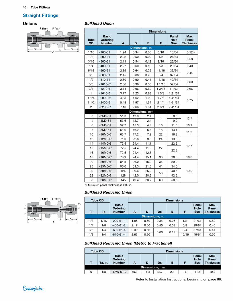
Bulkhead Union
➀ Minimum panel thickness is 0.06 in.
D DA
E
F flatF flat F flat
Unions
Tube OD
Basic Ordering Number
Dimensions
A D E F
Panel Hole Size
Max Panel
Thickness
Dimensions, in. 1/16 -100-61 1.24 0.34 0.05 5/16 13/64 0.12➀
1/8 -200-61 2.02 0.50 0.09 1/2 21/64 0.50
3/16 -300-61 2.11 0.54 0.12 9/16 25/64
1/4 -400-61 2.27 0.60 0.19 5/8 29/64 0.40
5/16 -500-61 2.39 0.64 0.25 11/16 33/64 0.44
3/8 -600-61 2.45 0.66 0.28 3/4 37/64
1/2 -810-61 2.80 0.90 0.41 15/16 49/64 0.50
5/8 -1010-61 2.86 0.96 0.50 1 1/16 57/64
3/4 -1210-61 3.11 0.96 0.62 1 3/16 1 1/64 0.66
1 -1610-61 3.77 1.23 0.88 1 5/8 1 21/64
0.75 1 1/4 -2000-61 4.85 1.62 1.09 1 7/8 1 41/64
1 1/2 -2400-61 5.48 1.97 1.34 2 1/4 1 61/64
2 -3200-61 7.10 2.66 1.81 2 3/4 2 41/64
Dimensions, mm 3 -3M0-61 51.3 12.9 2.4
14 8.3
12.7 4 -4M0-61 53.6 13.7 2.4 9.9
6 -6M0-61 57.7 15.3 4.8 16 11.5 10.2
8 -8M0-61 61.0 16.2 6.4 18 13.1 11.2
10 -10M0-61 63.7 17.2 7.9 22 16.3
12 -12M0-61 71.0 22.8 9.5 24 19.5
12.7 14 -14M0-61 72.5 24.4 11.1
27
22.5
15 -15M0-61 72.5 24.4 11.9 22.8
16 -16M0-61 72.5 24.4 12.7
18 -18M0-61 78.9 24.4 15.1 30 26.0 16.8
20 -20M0-61 84.5 26.0 15.9 35 29.0
19.0
25 -25M0-61 96.0 31.3 21.8 41 34.0
30 -30M0-61 124 39.6 26.2 50
40.5
32 -32M0-61 128 42.0 28.6 42.5
38 -38M0-61 145 49.4 33.7 60 50.5
Bulkhead Reducing Union (Metric to Fractional)
Tube OD
Basic OrderingNumber
Dimensions
T Tx, in. A D Dx E F
Panel Hole Size
Max Panel
Thickness
Dimensions, mm 6 1/8 -6M0-61-2 55.1 15.3 12.7 2.4 16 11.5 10.2
Straight Fittings
Bulkhead Reducing Union
D DxA
E
F flatF flat F flat
TxTube OD
Basic OrderingNumber
Dimensions
T Tx A D Dx E F
Panel Hole Size
Max Panel
Thickness
Dimensions, in. 1/8 1/16 -200-61-1 1.85 0.50 0.34 0.05 1/2 21/64 0.50
1/4 1/8 -400-61-2 2.17 0.60 0.50 0.09 5/8 29/64 0.40
3/8 1/4 -600-61-4 2.39 0.66 0.60 0.19
3/4 37/64 0.44
1/2 1/4 -810-61-4 2.63 0.90 15/16 49/64 0.50
T
Refer to Installation Instructions, beginning on page 68.

Gaugeable Tube Fittings and Adapter Fittings 17 TUBE
FITTINGSMale Connectors
NPT
➀ The E dimension is the minimum nominal opening. These fittings may have a larger opening at the pipe/straight thread end.
DA
E
F flat
➀ The E dimension is the minimum nominal opening. These fittings may have a larger opening at the pipe/straight thread end.
Tube OD
NPT Size
Basic Ordering Number
Dimensions
A D E➀ F
Dimensions, in.
1/16 1/16 1/8 1/4
-100-1-1 -100-1-2 -100-1-4
0.94 1.03 1.22
0.34 0.05 5/16 7/16 9/16
1/8
1/16 1/8 1/4 3/8 1/2
-200-1-1 -200-1-2 -200-1-4 -200-1-6 -200-1-8
1.17 1.20 1.40 1.41 1.66
0.50 0.09
7/16 7/16 9/16 11/16 7/8
3/16 1/8 1/4
-300-1-2 -300-1-4
1.23 1.43 0.54 0.12 7/16
9/16
1/4
1/16 1/8 1/4 3/8 1/2 3/4
-400-1-1 -400-1-2 -400-1-4 -400-1-6 -400-1-8 -400-1-12
1.29 1.29 1.49 1.51 1.76 1.82
0.60
0.12 0.19 0.19 0.19 0.19 0.19
1/2 1/2 9/16 11/16 7/8
1 1/16
5/16 1/8 1/4 3/8
-500-1-2 -500-1-4 -500-1-6
1.34 1.52 1.54
0.64 0.19 0.25 0.25
9/16 9/16 11/16
3/8
1/8 1/4 3/8 1/2 3/4 1
-600-1-2 -600-1-4 -600-1-6 -600-1-8 -600-1-12 -600-1-16
1.39 1.57 1.57 1.82 1.88 2.14
0.66
0.19 0.28 0.28 0.28 0.28 0.28
5/8 5/8
11/16 7/8
1 1/16 1 3/8
1/2
1/8 1/4 3/8 1/2 3/4 1
-810-1-2 -810-1-4 -810-1-6 -810-1-8 -810-1-12 -810-1-16
1.53 1.71 1.71 1.93 1.99 2.25
0.90
0.19 0.28 0.38 0.41 0.41 0.41
13/16 13/16 13/16 7/8
1 1/16 1 3/8
5/8
1/4 3/8 1/2 3/4
-1010-1-4 -1010-1-6 -1010-1-8 -1010-1-12
1.74 1.74 1.93 1.99
0.96
0.28 0.38 0.47 0.50
15/16 15/16 15/16 1 1/16
3/4
3/8 1/2 3/4 1
-1210-1-6 -1210-1-8 -1210-1-12 -1210-1-16
1.80 1.99 1.99 2.25
0.96
0.41 0.47 0.62 0.62
1 1/16 1 1/16 1 1/16 1 3/8
7/8 1/2 3/4 1
-1410-1-8 -1410-1-12 -1410-1-16
1.99 1.99 2.25
1.02 0.47 0.62 0.72
1 3/16 1 3/16 1 3/8
1 1/2 3/4 1
-1610-1-8 -1610-1-12 -1610-1-16
2.26 2.26 2.45
1.23 0.47 0.62 0.88
1 3/8
1 1/8 1 B-1810-1-16 2.45 1.23 0.88 1 5/8
1 1/4 1 1 1/4
-2000-1-16 -2000-1-20 3.04 1.62 0.88
1.09 1 3/4
1 1/2 1 1/2 -2400-1-24 3.50 1.97 1.34 2 1/8
2 2 -3200-1-32 4.47 2.66 1.81 2 3/4
Tube OD
NPT Size in.
Basic Ordering Number
Dimensions
A D E➀ F
Dimensions, mm 2 1/8 -2M0-1-2 30.5 12.9 1.7 12
3 1/8 1/4
-3M0-1-2 -3M0-1-4
30.5 35.6 12.9 2.4 12
14
4 1/8 1/4
-4M0-1-2 -4M0-1-4
31.2 36.3 13.7 2.4 12
14
6
1/8 1/4 3/8 1/2
-6M0-1-2 -6M0-1-4 -6M0-1-6 -6M0-1-8
32.8 37.9 38.4 44.7
15.3 4.8
14 14 18 22
8
1/8 1/4 3/8 1/2
-8M0-1-2 -8M0-1-4 -8M0-1-6 -8M0-1-8
34.2 38.7 39.3 45.6
16.2
4.8 6.4 6.4 6.4
15 15 18 22
10
1/8 1/4 3/8 1/2 3/4
-10M0-1-2 -10M0-1-4 -10M0-1-6 -10M0-1-8 -10M0-1-12
36.3 40.9 40.9 46.5 48.0
17.2
4.8 7.1 7.9 7.9 7.9
18 18 18 22 27
12
1/8 1/4 3/8 1/2 3/4
-12M0-1-2 -12M0-1-4 -12M0-1-6 -12M0-1-8 -12M0-1-12
38.8 43.4 43.4 49.0 50.5
22.8
4.8 7.1 9.5 9.5 9.5
22 22 22 22 27
14 1/4 3/8 1/2
-14M0-1-4 -14M0-1-6 -14M0-1-8
44.1 44.1 49.0
24.4 7.1 9.5
11.1 24
15 1/2 -15M0-1-8 49.0 24.4 11.9 24
16 3/8 1/2 3/4
-16M0-1-6 -16M0-1-8 -16M0-1-12
44.1 49.0 50.5
24.4 9.5
11.9 12.7
24 24 27
18 1/2 3/4
-18M0-1-8 -18M0-1-12 50.5 24.4 11.9
15.1 27
20 1/2 3/4
-20M0-1-8 -20M0-1-12 52.3 26.0 11.9
15.9 30
22 3/4 1
-22M0-1-12 -22M0-1-16
52.357.1 26.0 15.9
18.3 30 35
25 1/2 3/4 1
-25M0-1-8 -25M0-1-12 -25M0-1-16
57.5 57.5 62.3
31.3 11.9 15.9 21.8
35
28
1 1 1/4
-28M0-1-16 -28M0-1-20
72.473.1 36.6 21.8 41
46
1 1 1/4
B-28M0-1-16 B-28M0-1-20
75.077.3 31.6 24.6 41
46
30 1 1/4 -30M0-1-20 77.2 39.6 26.2 46
32 1 1/4 -32M0-1-20 79.6 42.0 28.6 46
38 1 1/2 -38M0-1-24 91.6 49.4 33.7 55
Straight Fittings
Refer to Installation Instructions, beginning on page 68.
18 Tube FittingsTU
BE
FITTI
NGS
See page 9 for thread specifications.
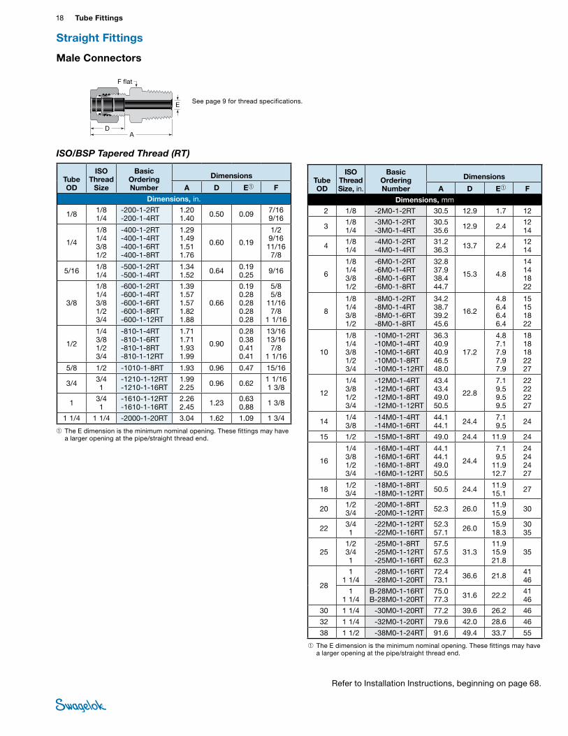
Male Connectors
ISO/BSP Tapered Thread (RT)
DA
E
F flat
➀ The E dimension is the minimum nominal opening. These fittings may have a larger opening at the pipe/straight thread end.
➀ The E dimension is the minimum nominal opening. These fittings may have a larger opening at the pipe/straight thread end.
Tube OD
ISO Thread
Size
Basic Ordering Number
Dimensions
A D E➀ F
Dimensions, in.
1/8 1/8 1/4
-200-1-2RT -200-1-4RT
1.20 1.40 0.50 0.09 7/16
9/16
1/4
1/8 1/4 3/8 1/2
-400-1-2RT -400-1-4RT -400-1-6RT -400-1-8RT
1.29 1.49 1.51 1.76
0.60 0.19
1/2 9/16 11/16 7/8
5/16 1/8 1/4
-500-1-2RT -500-1-4RT
1.34 1.52 0.64 0.19
0.25 9/16
3/8
1/8 1/4 3/8 1/2 3/4
-600-1-2RT -600-1-4RT -600-1-6RT -600-1-8RT -600-1-12RT
1.39 1.57 1.57 1.82 1.88
0.66
0.19 0.28 0.28 0.28 0.28
5/8 5/8
11/16 7/8
1 1/16
1/2
1/4 3/8 1/2 3/4
-810-1-4RT -810-1-6RT -810-1-8RT -810-1-12RT
1.71 1.71 1.93 1.99
0.90
0.28 0.38 0.41 0.41
13/16 13/16 7/8
1 1/16
5/8 1/2 -1010-1-8RT 1.93 0.96 0.47 15/16
3/4 3/4 1
-1210-1-12RT -1210-1-16RT
1.99 2.25 0.96 0.62 1 1/16
1 3/8
1 3/4 1
-1610-1-12RT -1610-1-16RT
2.26 2.45 1.23 0.63
0.88 1 3/8
1 1/4 1 1/4 -2000-1-20RT 3.04 1.62 1.09 1 3/4
Tube OD
ISO Thread Size, in.
Basic Ordering Number
Dimensions
A D E➀ F
Dimensions, mm 2 1/8 -2M0-1-2RT 30.5 12.9 1.7 12
3 1/8 1/4
-3M0-1-2RT -3M0-1-4RT
30.5 35.6 12.9 2.4 12
14
4 1/8 1/4
-4M0-1-2RT -4M0-1-4RT
31.2 36.3 13.7 2.4 12
14
6
1/8 1/4 3/8 1/2
-6M0-1-2RT -6M0-1-4RT -6M0-1-6RT -6M0-1-8RT
32.8 37.9 38.4 44.7
15.3 4.8
14 14 18 22
8
1/8 1/4 3/8 1/2
-8M0-1-2RT -8M0-1-4RT -8M0-1-6RT -8M0-1-8RT
34.2 38.7 39.2 45.6
16.2
4.8 6.4 6.4 6.4
15 15 18 22
10
1/8 1/4 3/8 1/2 3/4
-10M0-1-2RT -10M0-1-4RT -10M0-1-6RT -10M0-1-8RT -10M0-1-12RT
36.3 40.9 40.9 46.5 48.0
17.2
4.8 7.1 7.9 7.9 7.9
18 18 18 22 27
12
1/4 3/8 1/2 3/4
-12M0-1-4RT -12M0-1-6RT -12M0-1-8RT -12M0-1-12RT
43.4 43.4 49.0 50.5
22.8
7.1 9.5 9.5 9.5
22 22 22 27
14 1/4 3/8
-14M0-1-4RT -14M0-1-6RT
44.1 44.1 24.4 7.1
9.5 24
15 1/2 -15M0-1-8RT 49.0 24.4 11.9 24
16
1/4 3/8 1/2 3/4
-16M0-1-4RT -16M0-1-6RT -16M0-1-8RT -16M0-1-12RT
44.1 44.1 49.0 50.5
24.4
7.1 9.5
11.9 12.7
24 24 24 27
18 1/2 3/4
-18M0-1-8RT -18M0-1-12RT 50.5 24.4 11.9
15.1 27
20 1/2 3/4
-20M0-1-8RT -20M0-1-12RT 52.3 26.0 11.9
15.9 30
22 3/4 1
-22M0-1-12RT -22M0-1-16RT
52.3 57.1 26.0 15.9
18.3 30 35
25 1/2 3/4 1
-25M0-1-8RT -25M0-1-12RT -25M0-1-16RT
57.5 57.5 62.3
31.3 11.9 15.9 21.8
35
28
1 1 1/4
-28M0-1-16RT -28M0-1-20RT
72.4 73.1 36.6 21.8 41
46
1 1 1/4
B-28M0-1-16RTB-28M0-1-20RT
75.077.3 31.6 22.2 41
46
30 1 1/4 -30M0-1-20RT 77.2 39.6 26.2 46
32 1 1/4 -32M0-1-20RT 79.6 42.0 28.6 46
38 1 1/2 -38M0-1-24RT 91.6 49.4 33.7 55
Straight Fittings
Refer to Installation Instructions, beginning on page 68.
Gaugeable Tube Fittings and Adapter Fittings 19 TUBE
FITTINGS
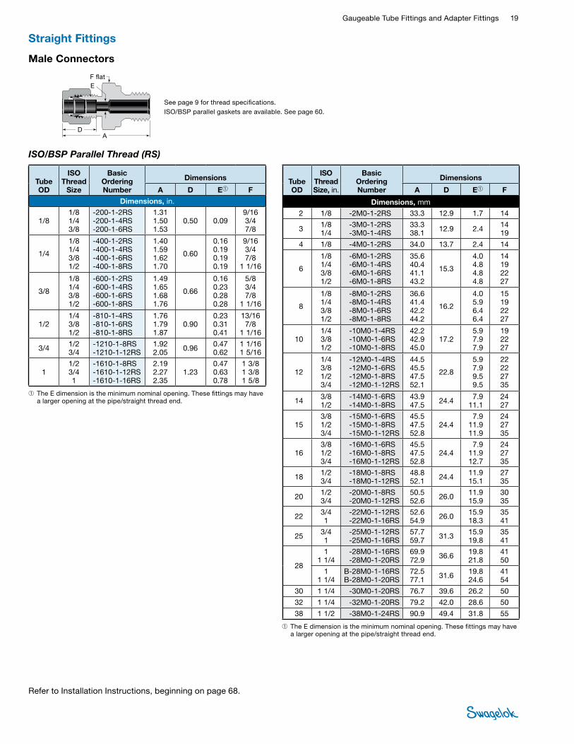
See page 9 for thread specifications.ISO/BSP parallel gaskets are available. See page 60.
Male Connectors
ISO/BSP Parallel Thread (RS)
DA
EF flat
➀ The E dimension is the minimum nominal opening. These fittings may have a larger opening at the pipe/straight thread end.
➀ The E dimension is the minimum nominal opening. These fittings may have a larger opening at the pipe/straight thread end.
Tube OD
ISO Thread
Size
Basic Ordering Number
Dimensions
A D E➀ F
Dimensions, in.
1/8 1/8 1/4 3/8
-200-1-2RS -200-1-4RS -200-1-6RS
1.31 1.50 1.53
0.50 0.09 9/16 3/4 7/8
1/4
1/8 1/4 3/8 1/2
-400-1-2RS -400-1-4RS -400-1-6RS -400-1-8RS
1.40 1.59 1.62 1.70
0.60
0.16 0.19 0.19 0.19
9/16 3/4 7/8
1 1/16
3/8
1/8 1/4 3/8 1/2
-600-1-2RS -600-1-4RS -600-1-6RS -600-1-8RS
1.49 1.65 1.68 1.76
0.66
0.16 0.23 0.28 0.28
5/8 3/4 7/8
1 1/16
1/2 1/4 3/8 1/2
-810-1-4RS -810-1-6RS -810-1-8RS
1.76 1.79 1.87
0.90 0.23 0.31 0.41
13/16 7/8
1 1/16
3/4 1/2 3/4
-1210-1-8RS -1210-1-12RS
1.92 2.05 0.96 0.47
0.62 1 1/16 1 5/16
1 1/2 3/4 1
-1610-1-8RS -1610-1-12RS -1610-1-16RS
2.19 2.27 2.35
1.23 0.47 0.63 0.78
1 3/8 1 3/8 1 5/8
Tube OD
ISO Thread Size, in.
Basic Ordering Number
Dimensions
A D E➀ F
Dimensions, mm 2 1/8 -2M0-1-2RS 33.3 12.9 1.7 14
3 1/8 1/4
-3M0-1-2RS -3M0-1-4RS
33.3 38.1 12.9 2.4 14
19
4 1/8 -4M0-1-2RS 34.0 13.7 2.4 14
6
1/8 1/4 3/8 1/2
-6M0-1-2RS -6M0-1-4RS -6M0-1-6RS -6M0-1-8RS
35.6 40.4 41.1 43.2
15.3
4.0 4.8 4.8 4.8
14 19 22 27
8
1/8 1/4 3/8 1/2
-8M0-1-2RS -8M0-1-4RS -8M0-1-6RS -8M0-1-8RS
36.6 41.4 42.2 44.2
16.2
4.0 5.9 6.4 6.4
15 19 22 27
10 1/4 3/8 1/2
-10M0-1-4RS -10M0-1-6RS -10M0-1-8RS
42.2 42.9 45.0
17.2 5.9 7.9 7.9
19 22 27
12
1/4 3/8 1/2 3/4
-12M0-1-4RS -12M0-1-6RS -12M0-1-8RS -12M0-1-12RS
44.5 45.5 47.5 52.1
22.8
5.9 7.9 9.5 9.5
22 22 27 35
14 3/8 1/2
-14M0-1-6RS -14M0-1-8RS
43.9 47.5 24.4 7.9
11.1 24 27
15 3/8 1/2 3/4
-15M0-1-6RS -15M0-1-8RS -15M0-1-12RS
45.5 47.5 52.8
24.4 7.9
11.9 11.9
24 27 35
16 3/8 1/2 3/4
-16M0-1-6RS -16M0-1-8RS -16M0-1-12RS
45.5 47.5 52.8
24.4 7.9
11.9 12.7
24 27 35
18 1/2 3/4
-18M0-1-8RS -18M0-1-12RS
48.8 52.1 24.4 11.9
15.1 27 35
20 1/2 3/4
-20M0-1-8RS -20M0-1-12RS
50.5 52.6 26.0 11.9
15.9 30 35
22 3/4 1
-22M0-1-12RS -22M0-1-16RS
52.6 54.9 26.0 15.9
18.3 35 41
25 3/4 1
-25M0-1-12RS -25M0-1-16RS
57.7 59.7 31.3 15.9
19.8 35 41
28
1 1 1/4
-28M0-1-16RS -28M0-1-20RS
69.9 72.9 36.6 19.8
21.8 41 50
1 1 1/4
B-28M0-1-16RS B-28M0-1-20RS
72.5 77.1 31.6 19.8
24.6 41 54
30 1 1/4 -30M0-1-20RS 76.7 39.6 26.2 50
32 1 1/4 -32M0-1-20RS 79.2 42.0 28.6 50
38 1 1/2 -38M0-1-24RS 90.9 49.4 31.8 55
Straight Fittings
Refer to Installation Instructions, beginning on page 68.

20 Tube FittingsTU
BE
FITTI
NGS
See page 9 for thread specifications.ISO/BSP parallel gaskets are available. See page 60.
Male Connectors
ISO/BSP Parallel Thread (RP)
DA
E
F flat
Bored-Through Fittings for Thermocouples, Dip Tubes, and Heat Exchanger Tees
Swagelok bored-through male connectors accommodate thermocouples or dip tubes. Most male connectors are available as a bored-through fitting, but male connectors whose pipe thread end is small relative to the tube fitting end—such as -600-1-2 or -8M0-1-2RT—cannot be bored through.
Swagelok bored-through reducers and standard Swagelok tees can be used to create a heat exchanger tee.
To order bored-through fittings, add BT to the ordering number. Example: SS-400-1-4BT
Bored-through fittings have a reduced pressure rating. In general, we have multiplied the allowable working pressure of the tubing, as found on the Tubing Data Sheet, MS-01-107, by the factors in the table to the right.
➀ The E dimension is the minimum nominal opening. These fittings may have a larger opening at the pipe/straight thread end.
➀ The E dimension is the minimum nominal opening. These fittings may have a larger opening at the pipe/straight thread end.
Tube OD
ISO Thread
Size
Basic Ordering Number
Dimensions
A D E➀ F
Dimensions, in.
1/8 1/8 1/4
-200-1-2RP -200-1-4RP
1.31 1.50 0.50 0.09 9/16
3/4
1/4 1/8 1/4
-400-1-2RP -400-1-4RP
1.40 1.59 0.60 0.16
0.199/16 3/4
1/2 3/8 1/2
-810-1-6RP -810-1-8RP
1.79 1.87 0.90 0.31
0.41 7/8
1 1/16
3/4 1/2 3/4
-1210-1-8RP -1210-1-12RP
1.92 2.05 0.96 0.47
0.62 1 1/16 1 5/16
1 1 -1610-1-16RP 2.35 1.23 0.78 1 5/8
Tube OD
ISO Thread Size, in.
Basic Ordering Number
Dimensions
A D E➀ F
Dimensions, mm
3 1/8 1/4
-3M0-1-2RP -3M0-1-4RP
33.3 38.1 12.9 2.4 14
19
4 1/8 -4M0-1-2RP 34.0 13.7 2.4 14
6
1/8 1/4 3/8 1/2
-6M0-1-2RP -6M0-1-4RP -6M0-1-6RP -6M0-1-8RP
35.6 40.4 41.2 43.2
15.3
4.0 4.8 4.8 4.8
14 19 22 27
8
1/8 1/4 3/8 1/2
-8M0-1-2RP -8M0-1-4RP -8M0-1-6RP -8M0-1-8RP
36.5 41.3 41.9 44.1
16.2
4.0 5.9 6.4 6.4
15 19 22 27
10 1/4 3/8 1/2
-10M0-1-4RP -10M0-1-6RP -10M0-1-8RP
42.2 42.9 45.0
17.2 5.9 7.9 7.9
19 22 27
12
1/4 3/8 1/2 3/4
-12M0-1-4RP -12M0-1-6RP -12M0-1-8RP -12M0-1-12RP
45.4 45.4 47.5 52.1
22.8
5.9 7.9 9.5 9.5
22 22 27 35
15 1/2 -15M0-1-8RP 47.5 24.4 11.9 27
16 3/8 1/2
-16M0-1-6RP -16M0-1-8RP
45.4 47.5 24.4 7.9
11.9 24 27
18 1/2 3/4
-18M0-1-8RP -18M0-1-12RP
49.0 52.3 24.4 11.9
15.1 27 35
20 1/2 3/4
-20M0-1-8RP -20M0-1-12RP
50.5 52.5 26.0 11.9
15.9 30 35
22 3/4 1
-22M0-1-12RP -22M0-1-16RP
52.8 54.5 26.0 15.9
18.3 35 41
25 3/4 1
-25M0-1-12RP -25M0-1-16RP
57.8 59.8 31.3 15.9
19.8 35 41
28
1 1 1/4
-28M0-1-16RP -28M0-1-20RP
69.8 72.9 36.6 19.8
21.8 41 50
1 1 1/4
B-28M0-1-16RP B-28M0-1-20RP
72.5 77.1 31.6 19.8
24.6 41 54
30 1 1/4 -30M0-1-20RP 76.8 39.6 26.2 50
32 1 1/4 -32M0-1-20RP 79.2 42.0 28.6 50
38 1 1/2 -38M0-1-24RP 92.1 49.4 31.8 55
Straight Fittings
Refer to Installation Instructions, beginning on page 68.
Size (in.) Size (mm) FactorUp to 1/2 in. Up to 12 mm 0.75
Above 1/2 in. to 3/4 in. Above 12 mm to 18 mm 0.50
Above 3/4 in. Above 18 mm 0.25
Reduced Pressure Rating Factors
Gaugeable Tube Fittings and Adapter Fittings 21 TUBE
FITTINGS
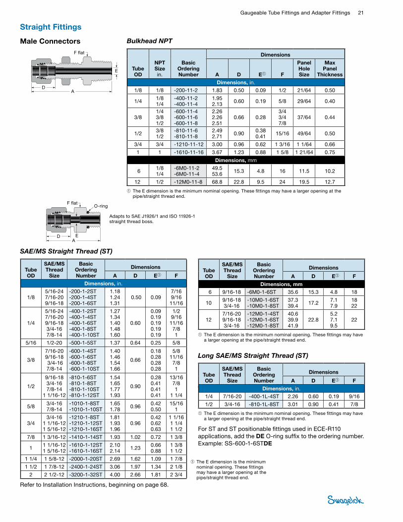
SAE/MS Straight Thread (ST)
Adapts to SAE J1926/1 and ISO 11926-1 straight thread boss.
Male Connectors Bulkhead NPT
DA
E
F flat
DA
E
F flatO-ring
➀ The E dimension is the minimum nominal opening. These fittings may have a larger opening at the pipe/straight thread end.
➀ The E dimension is the minimum nominal opening. These fittings may have a larger opening at the pipe/straight thread end.
➀ The E dimension is the minimum nominal opening. These fittings may have a larger opening at the pipe/straight thread end.
Long SAE/MS Straight Thread
Tube OD
NPT Size in.
Basic Ordering Number
Dimensions
A D E➀ F
Panel Hole Size
Max Panel
Thickness
Dimensions, in. 1/8 1/8 -200-11-2 1.83 0.50 0.09 1/2 21/64 0.50
1/4 1/8 1/4
-400-11-2 -400-11-4
1.95 2.13 0.60 0.19 5/8 29/64 0.40
3/8 1/4 3/8 1/2
-600-11-4 -600-11-6 -600-11-8
2.26 2.26 2.51
0.66 0.28 3/4 3/4 7/8
37/64 0.44
1/2 3/8 1/2
-810-11-6 -810-11-8
2.49 2.71 0.90 0.38
0.41 15/16 49/64 0.50
3/4 3/4 -1210-11-12 3.00 0.96 0.62 1 3/16 1 1/64 0.66
1 1 -1610-11-16 3.67 1.23 0.88 1 5/8 1 21/64 0.75
Dimensions, mm
6 1/8 1/4
-6M0-11-2 -6M0-11-4
49.5 53.6 15.3 4.8 16 11.5 10.2
12 1/2 -12M0-11-8 68.8 22.8 9.5 24 19.5 12.7
Tube OD
SAE/MS Thread
Size
Basic Ordering Number
Dimensions
A D E➀ F
Dimensions, in.
1/8 5/16-24 7/16-20 9/16-18
-200-1-2ST -200-1-4ST -200-1-6ST
1.18 1.24 1.31
0.50 0.09 7/16 9/16 11/16
1/4
5/16-24 7/16-20 9/16-18 3/4-16 7/8-14
-400-1-2ST -400-1-4ST -400-1-6ST -400-1-8ST -400-1-10ST
1.27 1.34 1.40 1.48 1.60
0.60
0.09 0.19 0.19 0.19 0.19
1/2 9/16 11/16 7/8 1
5/16 1/2-20 -500-1-5ST 1.37 0.64 0.25 5/8
3/8
7/16-20 9/16-18 3/4-16 7/8-14
-600-1-4ST -600-1-6ST -600-1-8ST -600-1-10ST
1.40 1.46 1.54 1.66
0.66
0.18 0.28 0.28 0.28
5/8 11/16 7/8 1
1/2
9/16-18 3/4-16 7/8-14
1 1/16-12
-810-1-6ST -810-1-8ST -810-1-10ST -810-1-12ST
1.54 1.65 1.77 1.93
0.90
0.28 0.41 0.41 0.41
13/16 7/8 1
1 1/4
5/8 3/4-16 7/8-14
-1010-1-8ST -1010-1-10ST
1.65 1.78 0.96 0.42
0.50 15/16
1
3/4 3/4-16
1 1/16-12 1 5/16-12
-1210-1-8ST -1210-1-12ST -1210-1-16ST
1.81 1.93 1.96
0.96 0.42 0.62 0.63
1 1/16 1 1/4 1 1/2
7/8 1 3/16-12 -1410-1-14ST 1.93 1.02 0.72 1 3/8
1 1 1/16-12 1 5/16-12
-1610-1-12ST -1610-1-16ST
2.10 2.14 1.23 0.66
0.88 1 3/8 1 1/2
1 1/4 1 5/8-12 -2000-1-20ST 2.69 1.62 1.09 1 7/8
1 1/2 1 7/8-12 -2400-1-24ST 3.06 1.97 1.34 2 1/8
2 2 1/2-12 -3200-1-32ST 4.00 2.66 1.81 2 3/4
Tube OD
SAE/MS Thread
Size
Basic Ordering Number
Dimensions
A D E➀ F
Dimensions, mm 6 9/16-18 -6M0-1-6ST 35.6 15.3 4.8 18
10 9/16-18 3/4-16
-10M0-1-6ST -10M0-1-8ST
37.3 39.4 17.2 7.1
7.9 18 22
12 7/16-20 9/16-18 3/4-16
-12M0-1-4ST -12M0-1-6ST -12M0-1-8ST
40.6 39.9 41.9
22.8 5.2 7.1 9.5
22
➀ The E dimension is the minimum nominal opening. These fittings may have a larger opening at the pipe/straight thread end.
Tube OD
SAE/MS Thread
Size
Basic Ordering Number
Dimensions
A D E➀ F
Dimensions, in.
1/4 7/16-20 -400-1L-4ST 2.26 0.60 0.19 9/16
1/2 3/4-16 -810-1L-8ST 3.01 0.90 0.41 7/8
Long SAE/MS Straight Thread (ST)
Straight Fittings
Refer to Installation Instructions, beginning on page 68.
For ST and ST positionable fittings used in ECE-R110 applications, add the DE O-ring suffix to the ordering number. Example: SS-600-1-6STDE
22 Tube FittingsTU
BE
FITTI
NGS
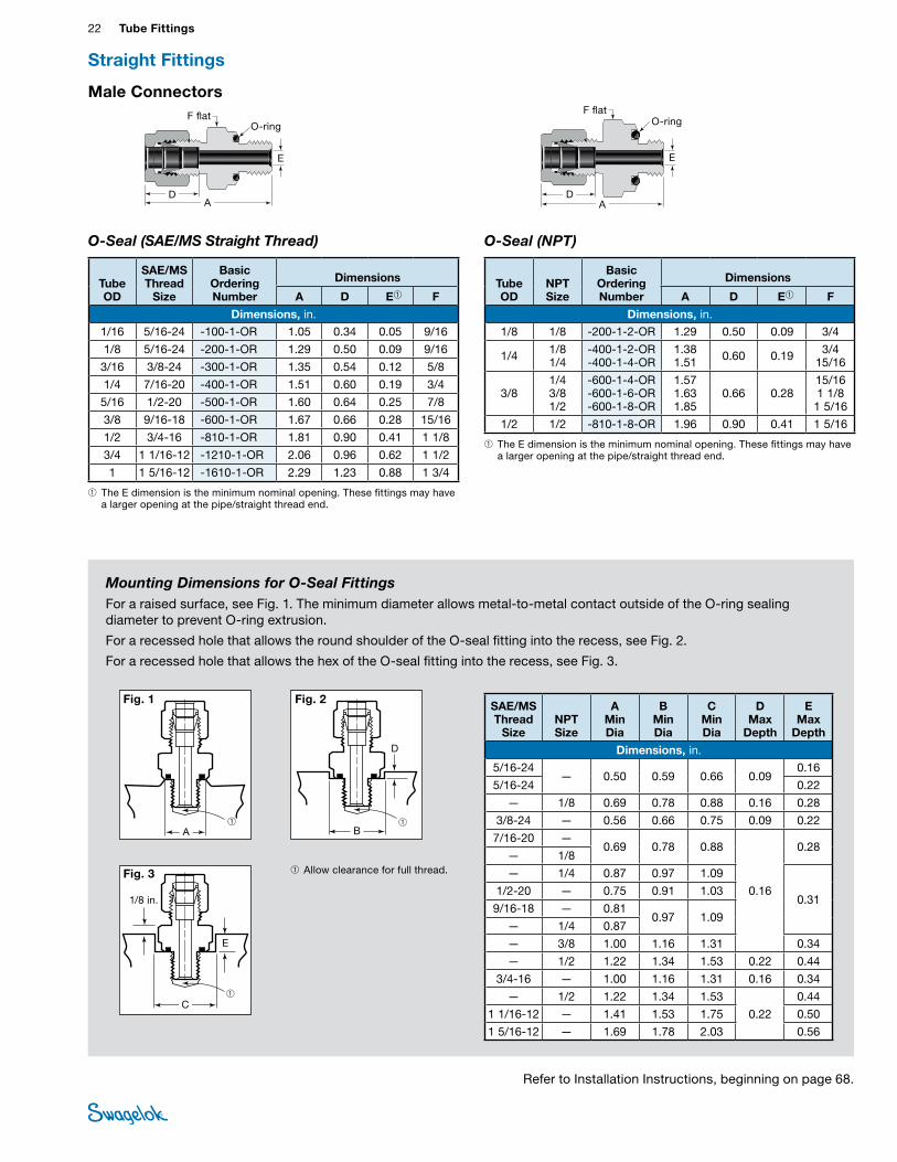
Mounting Dimensions for O-Seal FittingsFor a raised surface, see Fig. 1. The minimum diameter allows metal-to-metal contact outside of the O-ring sealing diameter to prevent O-ring extrusion.
For a recessed hole that allows the round shoulder of the O-seal fitting into the recess, see Fig. 2.
For a recessed hole that allows the hex of the O-seal fitting into the recess, see Fig. 3.
1/8 in.
Fig. 3
O-Seal (SAE/MS Straight Thread) O-Seal (NPT)
➀ The E dimension is the minimum nominal opening. These fittings may have a larger opening at the pipe/straight thread end.
➀ The E dimension is the minimum nominal opening. These fittings may have a larger opening at the pipe/straight thread end.
DA
E
F flatO-ring
DA
E
F flatO-ring
Male Connectors
➀ Allow clearance for full thread.
➀
Fig. 1
A
➀C
E
➀B
D
Fig. 2
Tube OD
SAE/MS Thread
Size
Basic Ordering Number
Dimensions
A D E➀ F
Dimensions, in.
1/16 5/16-24 -100-1-OR 1.05 0.34 0.05 9/16
1/8 5/16-24 -200-1-OR 1.29 0.50 0.09 9/16
3/16 3/8-24 -300-1-OR 1.35 0.54 0.12 5/8
1/4 7/16-20 -400-1-OR 1.51 0.60 0.19 3/4
5/16 1/2-20 -500-1-OR 1.60 0.64 0.25 7/8
3/8 9/16-18 -600-1-OR 1.67 0.66 0.28 15/16
1/2 3/4-16 -810-1-OR 1.81 0.90 0.41 1 1/8
3/4 1 1/16-12 -1210-1-OR 2.06 0.96 0.62 1 1/2
1 1 5/16-12 -1610-1-OR 2.29 1.23 0.88 1 3/4
Tube OD
NPT Size
Basic Ordering Number
Dimensions
A D E➀ F
Dimensions, in. 1/8 1/8 -200-1-2-OR 1.29 0.50 0.09 3/4
1/4 1/8 1/4
-400-1-2-OR -400-1-4-OR
1.38 1.51 0.60 0.19 3/4
15/16
3/8 1/4 3/8 1/2
-600-1-4-OR -600-1-6-OR -600-1-8-OR
1.57 1.63 1.85
0.66 0.28 15/16 1 1/8 1 5/16
1/2 1/2 -810-1-8-OR 1.96 0.90 0.41 1 5/16
SAE/MS Thread
Size NPT Size
A Min Dia
B Min Dia
C Min Dia
D Max
Depth
E Max
Depth
Dimensions, in. 5/16-24
— 0.50 0.59 0.66 0.09 0.16
5/16-24 0.22
— 1/8 0.69 0.78 0.88 0.16 0.28
3/8-24 — 0.56 0.66 0.75 0.09 0.22
7/16-20 — 0.69 0.78 0.88
0.16
0.28— 1/8
— 1/4 0.87 0.97 1.09
0.31 1/2-20 — 0.75 0.91 1.03
9/16-18 — 0.81 0.97 1.09
— 1/4 0.87
— 3/8 1.00 1.16 1.31 0.34
— 1/2 1.22 1.34 1.53 0.22 0.44
3/4-16 — 1.00 1.16 1.31 0.16 0.34
— 1/2 1.22 1.34 1.53
0.22
0.44
1 1/16-12 — 1.41 1.53 1.75 0.50
1 5/16-12 — 1.69 1.78 2.03 0.56
Straight Fittings
Refer to Installation Instructions, beginning on page 68.
Gaugeable Tube Fittings and Adapter Fittings 23 TUBE
FITTINGS
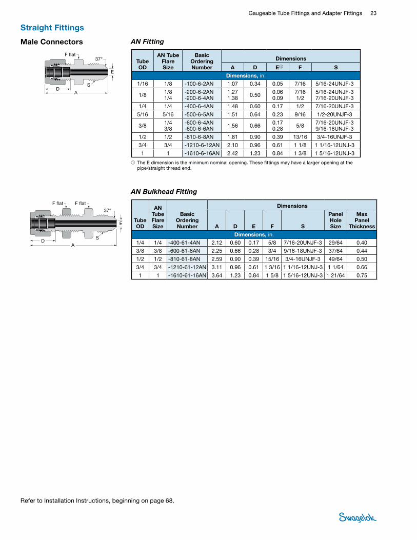
Male Connectors
➀ The E dimension is the minimum nominal opening. These fittings may have a larger opening at the pipe/straight thread end.
AN Bulkhead Fitting
AN Fitting
DA
E
S
F flat F flat
DA
E
F flat37°
37°
S
Tube OD
AN Tube Flare Size
Basic Ordering Number
Dimensions
A D E➀ F S
Dimensions, in. 1/16 1/8 -100-6-2AN 1.07 0.34 0.05 7/16 5/16-24UNJF-3
1/8 1/8 1/4
-200-6-2AN -200-6-4AN
1.27 1.38 0.50 0.06
0.09 7/16 1/2
5/16-24UNJF-3 7/16-20UNJF-3
1/4 1/4 -400-6-4AN 1.48 0.60 0.17 1/2 7/16-20UNJF-3
5/16 5/16 -500-6-5AN 1.51 0.64 0.23 9/16 1/2-20UNJF-3
3/8 1/4 3/8
-600-6-4AN -600-6-6AN 1.56 0.66 0.17
0.28 5/8 7/16-20UNJF-3 9/16-18UNJF-3
1/2 1/2 -810-6-8AN 1.81 0.90 0.39 13/16 3/4-16UNJF-3
3/4 3/4 -1210-6-12AN 2.10 0.96 0.61 1 1/8 1 1/16-12UNJ-3
1 1 -1610-6-16AN 2.42 1.23 0.84 1 3/8 1 5/16-12UNJ-3
Tube OD
AN Tube Flare Size
Basic Ordering Number
Dimensions
A D E F S
Panel Hole Size
Max Panel
Thickness
Dimensions, in.
1/4 1/4 -400-61-4AN 2.12 0.60 0.17 5/8 7/16-20UNJF-3 29/64 0.40
3/8 3/8 -600-61-6AN 2.25 0.66 0.28 3/4 9/16-18UNJF-3 37/64 0.44
1/2 1/2 -810-61-8AN 2.59 0.90 0.39 15/16 3/4-16UNJF-3 49/64 0.50
3/4 3/4 -1210-61-12AN 3.11 0.96 0.61 1 3/16 1 1/16-12UNJ-3 1 1/64 0.66
1 1 -1610-61-16AN 3.64 1.23 0.84 1 5/8 1 5/16-12UNJ-3 1 21/64 0.75
Straight Fittings
Refer to Installation Instructions, beginning on page 68.
24 Tube FittingsTU
BE
FITTI
NGS
Weld Connectors Tube Socket Weld
D BA
J
E
Tube OD
Socket Weld Size
Basic Ordering Number
Dimensions
A B D E J
Dimensions, in.
1/8 1/8 -200-6-2W 1.14 0.10 0.50 0.09 0.29
1/4 1/4 -400-6-4W 1.32 0.28 0.60 0.19 0.48
3/8 3/8 -600-6-6W 1.48 0.31 0.66 0.28 0.60
1/2 1/2 -810-6-8W 1.62 0.38 0.90 0.41 0.73
3/4 3/4 -1210-6-12W 1.71 0.44 0.96 0.62 1.04
1 1 -1610-6-16W 2.07 0.62 1.23 0.88 1.36
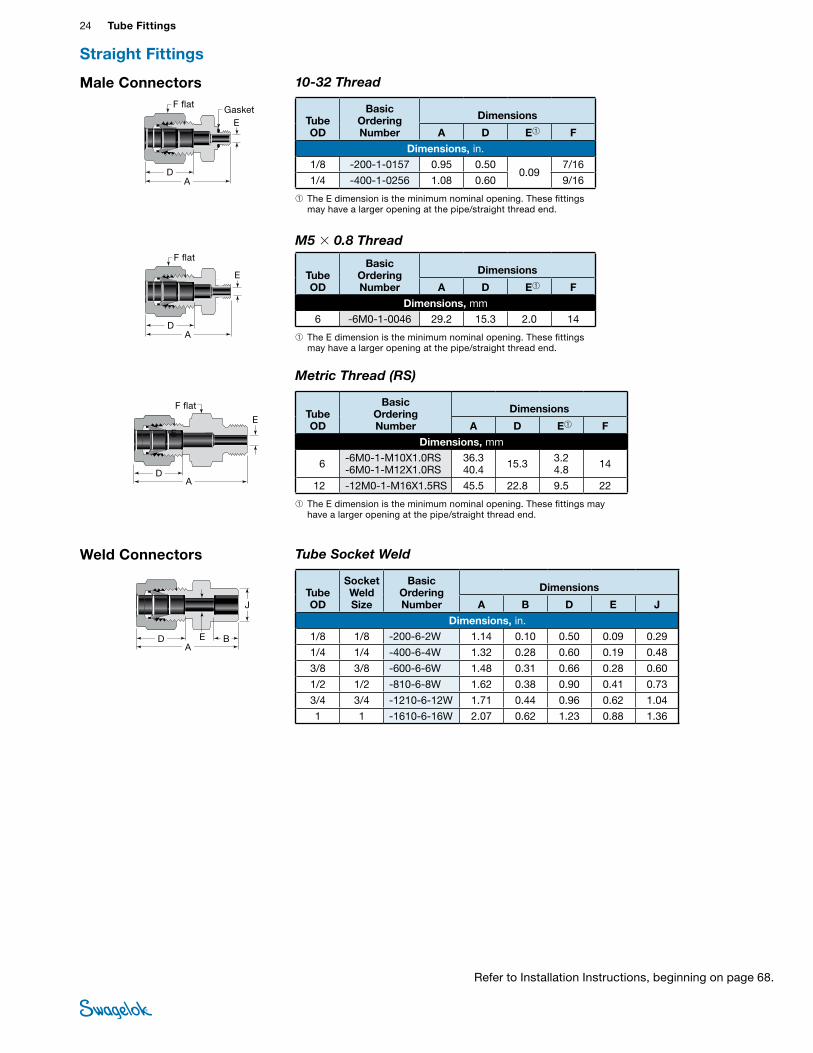
10-32 ThreadMale Connectors
DA
E
F flat
Tube OD
Basic Ordering Number
Dimensions
A D E➀ F
Dimensions, in. 1/8 -200-1-0157 0.95 0.50
0.09 7/16
1/4 -400-1-0256 1.08 0.60 9/16
➀ The E dimension is the minimum nominal opening. These fittings may have a larger opening at the pipe/straight thread end.
Gasket
M5 × 0.8 Thread
Tube OD
Basic Ordering Number
Dimensions
A D E➀ F
Dimensions, mm 6 -6M0-1-0046 29.2 15.3 2.0 14
DA
E
F flat
➀ The E dimension is the minimum nominal opening. These fittings may have a larger opening at the pipe/straight thread end.
Metric Thread (RS)
E
E
F flatTube OD
Basic Ordering Number
Dimensions
A D E➀ F
Dimensions, mm
6 -6M0-1-M10X1.0RS -6M0-1-M12X1.0RS
36.3 40.4 15.3 3.2
4.8 14
12 -12M0-1-M16X1.5RS 45.5 22.8 9.5 22
➀ The E dimension is the minimum nominal opening. These fittings may have a larger opening at the pipe/straight thread end.
AD
Straight Fittings
Refer to Installation Instructions, beginning on page 68.
Gaugeable Tube Fittings and Adapter Fittings 25 TUBE
FITTINGSSWAGELOK MALE PIPE WELD CONNECTOR CUTAWAY-MS-01-140 C-PH-0364-DIM
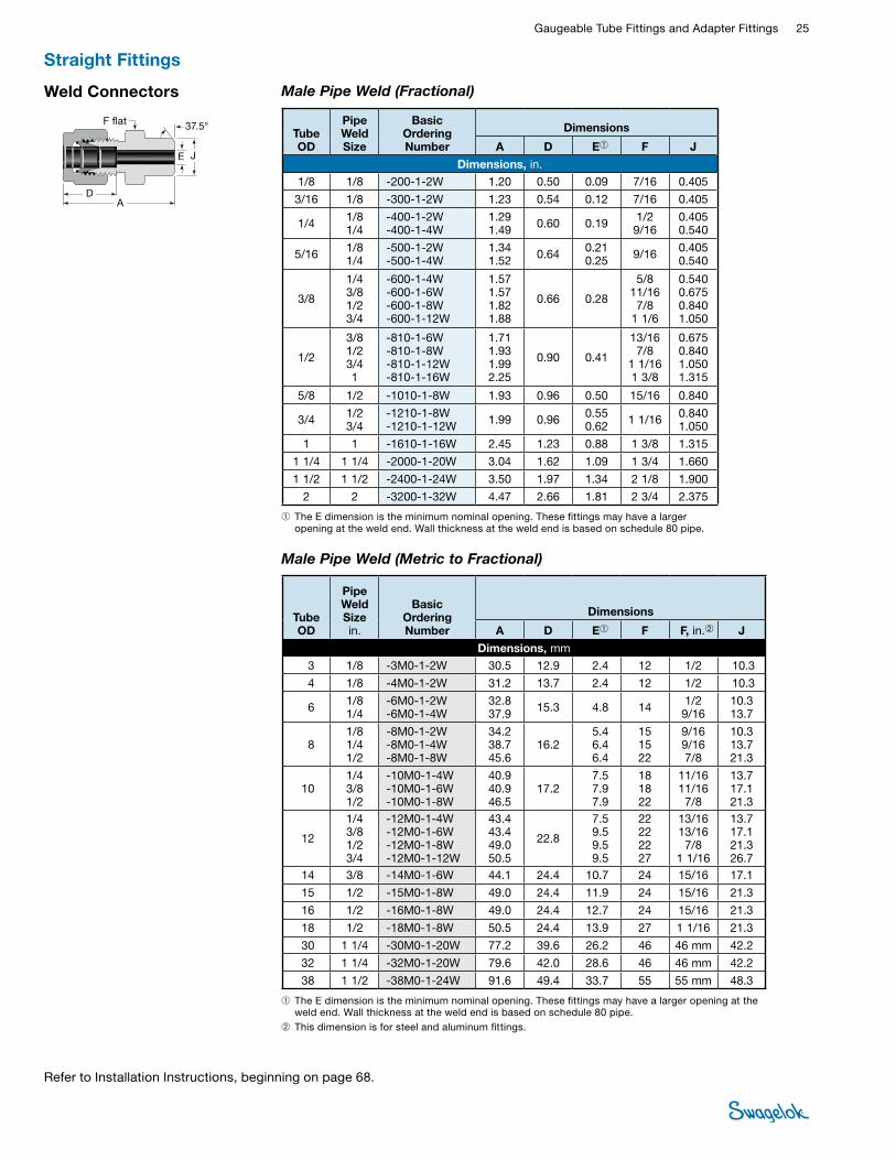
Weld Connectors
DA
E J
F flat 37.5°
Male Pipe Weld (Fractional)
➀ The E dimension is the minimum nominal opening. These fittings may have a larger opening at the weld end. Wall thickness at the weld end is based on schedule 80 pipe.
Tube OD
Pipe Weld Size
Basic Ordering Number
Dimensions
A D E➀ F J
Dimensions, in. 1/8 1/8 -200-1-2W 1.20 0.50 0.09 7/16 0.405
3/16 1/8 -300-1-2W 1.23 0.54 0.12 7/16 0.405
1/4 1/8 1/4
-400-1-2W -400-1-4W
1.29 1.49 0.60 0.19 1/2
9/16 0.405 0.540
5/16 1/8 1/4
-500-1-2W -500-1-4W
1.34 1.52 0.64 0.21
0.25 9/16 0.405 0.540
3/8
1/4 3/8 1/2 3/4
-600-1-4W -600-1-6W -600-1-8W -600-1-12W
1.57 1.57 1.82 1.88
0.66 0.28
5/8 11/16 7/8
1 1/6
0.540 0.675 0.840 1.050
1/2
3/8 1/2 3/4 1
-810-1-6W -810-1-8W -810-1-12W -810-1-16W
1.71 1.93 1.99 2.25
0.90 0.41
13/16 7/8
1 1/16 1 3/8
0.675 0.840 1.050 1.315
5/8 1/2 -1010-1-8W 1.93 0.96 0.50 15/16 0.840
3/4 1/2 3/4
-1210-1-8W -1210-1-12W 1.99 0.96 0.55
0.62 1 1/16 0.840 1.050
1 1 -1610-1-16W 2.45 1.23 0.88 1 3/8 1.315
1 1/4 1 1/4 -2000-1-20W 3.04 1.62 1.09 1 3/4 1.660
1 1/2 1 1/2 -2400-1-24W 3.50 1.97 1.34 2 1/8 1.900
2 2 -3200-1-32W 4.47 2.66 1.81 2 3/4 2.375
Male Pipe Weld (Metric to Fractional)
➀ The E dimension is the minimum nominal opening. These fittings may have a larger opening at the weld end. Wall thickness at the weld end is based on schedule 80 pipe.
➁ This dimension is for steel and aluminum fittings.
Tube OD
Pipe Weld Size in.
Basic Ordering Number
Dimensions
A D E➀ F F, in.➁ J
Dimensions, mm 3 1/8 -3M0-1-2W 30.5 12.9 2.4 12 1/2 10.3
4 1/8 -4M0-1-2W 31.2 13.7 2.4 12 1/2 10.3
6 1/8 1/4
-6M0-1-2W -6M0-1-4W
32.8 37.9 15.3 4.8 14 1/2
9/16 10.3 13.7
8 1/8 1/4 1/2
-8M0-1-2W -8M0-1-4W -8M0-1-8W
34.2 38.7 45.6
16.2 5.4 6.4 6.4
15 15 22
9/16 9/16 7/8
10.3 13.7 21.3
10 1/4 3/8 1/2
-10M0-1-4W -10M0-1-6W -10M0-1-8W
40.9 40.9 46.5
17.2 7.5 7.9 7.9
18 18 22
11/16 11/16 7/8
13.7 17.1 21.3
12
1/4 3/8 1/2 3/4
-12M0-1-4W -12M0-1-6W -12M0-1-8W -12M0-1-12W
43.4 43.4 49.0 50.5
22.8
7.5 9.5 9.5 9.5
22 22 22 27
13/16 13/16 7/8
1 1/16
13.7 17.1 21.3 26.7
14 3/8 -14M0-1-6W 44.1 24.4 10.7 24 15/16 17.1
15 1/2 -15M0-1-8W 49.0 24.4 11.9 24 15/16 21.3
16 1/2 -16M0-1-8W 49.0 24.4 12.7 24 15/16 21.3
18 1/2 -18M0-1-8W 50.5 24.4 13.9 27 1 1/16 21.3
30 1 1/4 -30M0-1-20W 77.2 39.6 26.2 46 46 mm 42.2
32 1 1/4 -32M0-1-20W 79.6 42.0 28.6 46 46 mm 42.2
38 1 1/2 -38M0-1-24W 91.6 49.4 33.7 55 55 mm 48.3
Straight Fittings
Refer to Installation Instructions, beginning on page 68.
26 Tube FittingsTU
BE
FITTI
NGS
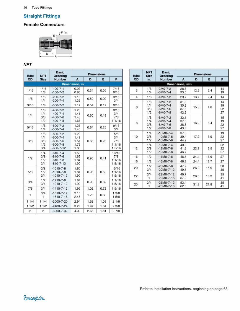
Female Connectors
NPT
AD
EF flat
Tube OD
NPT Size
Basic Ordering Number
Dimensions
A D E F
Dimensions, in.
1/16 1/16 1/8
-100-7-1 -100-7-2
0.93 0.96 0.34 0.05 7/16
9/16
1/8 1/8 1/4
-200-7-2 -200-7-4
1.13 1.32 0.50 0.09 9/16
3/4
3/16 1/8 -300-7-2 1.17 0.54 0.12 9/16
1/4
1/8 1/4 3/8 1/2
-400-7-2 -400-7-4 -400-7-6 -400-7-8
1.23 1.41 1.48 1.67
0.60 0.19
9/16 3/4 7/8
1 1/16
5/16 1/8 1/4
-500-7-2 -500-7-4
1.26 1.45 0.64 0.25 9/16
3/4
3/8
1/8 1/4 3/8 1/2 3/4
-600-7-2 -600-7-4 -600-7-6 -600-7-8 -600-7-12
1.29 1.48 1.54 1.73 1.88
0.66 0.28
5/8 3/47/8
1 1/16 1 5/16
1/2
1/4 3/8 1/2 3/4
-810-7-4 -810-7-6 -810-7-8 -810-7-12
1.59 1.65 1.84 1.90
0.90 0.41
13/16 7/8
1 1/16 1 5/16
5/8 3/8 1/2 3/4
-1010-7-6 -1010-7-8 -1010-7-12
1.65 1.84 1.90
0.96 0.50 15/16 1 1/16 1 5/16
3/4 1/2 3/4
-1210-7-8 -1210-7-12
1.84 1.90 0.96 0.62 1 1/16
1 5/16
7/8 3/4 -1410-7-12 1.96 1.02 0.72 1 5/16
1 3/4 1
-1610-7-12 -1610-7-16
2.10 2.45 1.23 0.88 1 3/8
1 5/8
1 1/4 1 1/4 -2000-7-20 2.94 1.62 1.09 2 1/8
1 1/2 1 1/2 -2400-7-24 3.28 1.97 1.34 2 3/8
2 2 -3200-7-32 4.00 2.66 1.81 2 7/8
Tube OD
NPT Sizein.
Basic Ordering Number
Dimensions
A D E F
Dimensions, mm
3 1/8 1/4
-3M0-7-2 -3M0-7-4
28.7 33.5 12.9 2.4 14
19
4 1/8 -4M0-7-2 29.7 13.7 2.4 14
6
1/8 1/4 3/8 1/2
-6M0-7-2 -6M0-7-4 -6M0-7-6 -6M0-7-8
31.3 35.8 37.6 42.5
15.3 4.8
14 19 22 27
8
1/8 1/4 3/8 1/2
-8M0-7-2 -8M0-7-4 -8M0-7-6 -8M0-7-8
32.1 37.0 38.5 43.3
16.2 6.4
15 19 22 27
10 1/4 3/8 1/2
-10M0-7-4 -10M0-7-6 -10M0-7-8
37.8 39.4 44.2
17.2 7.9 19 22 27
12 1/4 3/8 1/2
-12M0-7-4 -12M0-7-6 -12M0-7-8
40.3 41.9 46.7
22.8 9.5 22 22 27
15 1/2 -15M0-7-8 46.7 24.4 11.9 27
16 1/2 -16M0-7-8 46.9 24.4 12.7 27
20 1/2 3/4
-20M0-7-8 -20M0-7-12
47.9 49.7 26.0 15.9 30
35
22 3/4 1
-22M0-7-12 -22M0-7-16
49.7 57.9 26.0 18.3 35
41
25 3/4 1
-25M0-7-12 -25M0-7-16
53.4 62.3 31.3 21.8 35
41
Straight Fittings
Refer to Installation Instructions, beginning on page 68.
Gaugeable Tube Fittings and Adapter Fittings 27 TUBE
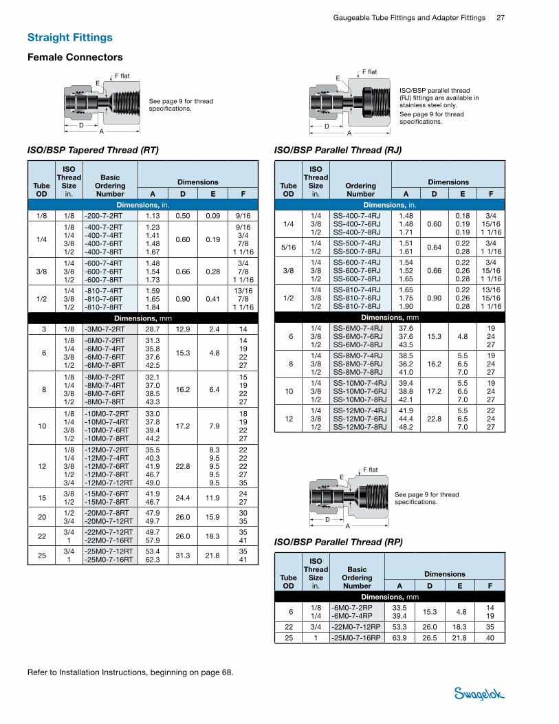
FITTINGSFemale Connectors
ISO/BSP Parallel Thread (RJ)
AD
EF flat
AD
EF flat
See page 9 for thread specifications.
ISO/BSP parallel thread (RJ) fittings are available in stainless steel only.See page 9 for thread specifications.
See page 9 for thread specifications.
ISO/BSP Parallel Thread (RP)
AD
EF flat
ISO/BSP Tapered Thread (RT)
Tube OD
ISO Thread
Size in.
Basic Ordering Number
Dimensions
A D E F
Dimensions, in.
1/8 1/8 -200-7-2RT 1.13 0.50 0.09 9/16
1/4
1/8 1/4 3/8 1/2
-400-7-2RT -400-7-4RT -400-7-6RT -400-7-8RT
1.23 1.41 1.48 1.67
0.60 0.19
9/16 3/4 7/8
1 1/16
3/8 1/4 3/8 1/2
-600-7-4RT -600-7-6RT -600-7-8RT
1.48 1.54 1.73
0.66 0.28 3/4 7/8
1 1/16
1/2 1/4 3/8 1/2
-810-7-4RT -810-7-6RT -810-7-8RT
1.59 1.65 1.84
0.90 0.41 13/16 7/8
1 1/16
Dimensions, mm
3 1/8 -3M0-7-2RT 28.7 12.9 2.4 14
6
1/8 1/4 3/8 1/2
-6M0-7-2RT -6M0-7-4RT -6M0-7-6RT -6M0-7-8RT
31.3 35.8 37.6 42.5
15.3 4.8
14 19 22 27
8
1/8 1/4 3/8 1/2
-8M0-7-2RT -8M0-7-4RT -8M0-7-6RT -8M0-7-8RT
32.1 37.0 38.5 43.3
16.2 6.4
15 19 22 27
10
1/8 1/4 3/8 1/2
-10M0-7-2RT -10M0-7-4RT -10M0-7-6RT -10M0-7-8RT
33.0 37.8 39.4 44.2
17.2 7.9
18 19 22 27
12
1/8 1/4 3/8 1/2 3/4
-12M0-7-2RT -12M0-7-4RT -12M0-7-6RT -12M0-7-8RT -12M0-7-12RT
35.5 40.3 41.9 46.7 49.0
22.8
8.3 9.5 9.5 9.5 9.5
22 22 22 27 35
15 3/8 1/2
-15M0-7-6RT -15M0-7-8RT
41.9 46.7 24.4 11.9 24
27
20 1/2 3/4
-20M0-7-8RT -20M0-7-12RT
47.9 49.7 26.0 15.9 30
35
22 3/4 1
-22M0-7-12RT -22M0-7-16RT
49.7 57.9 26.0 18.3 35
41
25 3/4 1
-25M0-7-12RT -25M0-7-16RT
53.4 62.3 31.3 21.8 35
41
Tube OD
ISO Thread
Size in.
Ordering Number
Dimensions
A D E F
Dimensions, in.
1/4 1/4 3/8 1/2
SS-400-7-4RJ SS-400-7-6RJ SS-400-7-8RJ
1.48 1.48 1.71
0.60 0.18 0.19 0.19
3/4 15/16 1 1/16
5/16 1/41/2
SS-500-7-4RJ SS-500-7-8RJ
1.51 1.61 0.64 0.22
0.283/4
1 1/16
3/8 1/4 3/8 1/2
SS-600-7-4RJ SS-600-7-6RJ SS-600-7-8RJ
1.54 1.52 1.65
0.66 0.22 0.26 0.28
3/4 15/16 1 1/16
1/2 1/4 3/8 1/2
SS-810-7-4RJ SS-810-7-6RJ SS-810-7-8RJ
1.65 1.75 1.90
0.90 0.22 0.26 0.28
13/16 15/16 1 1/16
Dimensions, mm
6 1/4 3/8 1/2
SS-6M0-7-4RJ SS-6M0-7-6RJ SS-6M0-7-8RJ
37.6 37.6 43.5
15.3 4.8 19 24 27
8 1/4 3/8 1/2
SS-8M0-7-4RJ SS-8M0-7-6RJ SS-8M0-7-8RJ
38.5 36.2 41.0
16.2 5.5 6.5 7.0
19 24 27
10 1/4 3/8 1/2
SS-10M0-7-4RJ SS-10M0-7-6RJ SS-10M0-7-8RJ
39.4 38.8 42.1
17.2 5.5 6.5 7.0
19 24 27
12 1/4 3/8 1/2
SS-12M0-7-4RJ SS-12M0-7-6RJ SS-12M0-7-8RJ
41.9 44.4 48.2
22.8 5.5 6.5 7.0
22 24 27
Tube OD
ISO Thread
Size in.
Basic Ordering Number
Dimensions
A D E F
Dimensions, mm
6 1/8 1/4
-6M0-7-2RP -6M0-7-4RP
33.5 39.4 15.3 4.8 14
19
22 3/4 -22M0-7-12RP 53.3 26.0 18.3 35
25 1 -25M0-7-16RP 63.9 26.5 21.8 40
Straight Fittings
Refer to Installation Instructions, beginning on page 68.
28 Tube FittingsTU
BE
FITTI
NGS
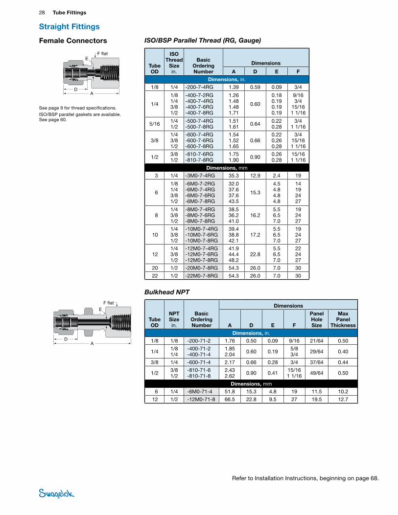
See page 9 for thread specifications.ISO/BSP parallel gaskets are available. See page 60.
Female Connectors ISO/BSP Parallel Thread (RG, Gauge)
AD
EF flat
Tube OD
ISO Thread
Size in.
Basic Ordering Number
Dimensions
A D E F
Dimensions, in.
1/8 1/4 -200-7-4RG 1.39 0.59 0.09 3/4
1/4
1/8 1/4 3/8 1/2
-400-7-2RG -400-7-4RG -400-7-6RG -400-7-8RG
1.26 1.48 1.48 1.71
0.60
0.18 0.19 0.19 0.19
9/16 3/4
15/16 1 1/16
5/16 1/4 1/2
-500-7-4RG -500-7-8RG
1.51 1.61 0.64 0.22
0.28 3/4
1 1/16
3/8 1/4 3/8 1/2
-600-7-4RG -600-7-6RG -600-7-8RG
1.54 1.52 1.65
0.66 0.22 0.26 0.28
3/4 15/16 1 1/16
1/2 3/8 1/2
-810-7-6RG -810-7-8RG
1.75 1.90 0.90 0.26
0.28 15/16 1 1/16
Dimensions, mm
3 1/4 -3M0-7-4RG 35.3 12.9 2.4 19
6
1/8 1/4 3/8 1/2
-6M0-7-2RG -6M0-7-4RG -6M0-7-6RG -6M0-7-8RG
32.0 37.6 37.6 43.5
15.3
4.5 4.8 4.8 4.8
14 19 24 27
8 1/4 3/8 1/2
-8M0-7-4RG -8M0-7-6RG -8M0-7-8RG
38.5 36.2 41.0
16.2 5.5 6.5 7.0
19 24 27
10 1/4 3/8 1/2
-10M0-7-4RG -10M0-7-6RG -10M0-7-8RG
39.4 38.8 42.1
17.2 5.5 6.5 7.0
19 24 27
12 1/4 3/8 1/2
-12M0-7-4RG -12M0-7-6RG -12M0-7-8RG
41.9 44.4 48.2
22.8 5.5 6.5 7.0
22 24 27
20 1/2 -20M0-7-8RG 54.3 26.0 7.0 30
22 1/2 -22M0-7-8RG 54.3 26.0 7.0 30
Bulkhead NPT
AD
EF flat
Tube OD
NPT Sizein.
Basic Ordering Number
Dimensions
A D E F
Panel Hole Size
Max Panel
Thickness
Dimensions, in.
1/8 1/8 -200-71-2 1.76 0.50 0.09 9/16 21/64 0.50
1/4 1/8 1/4
-400-71-2 -400-71-4
1.85 2.04 0.60 0.19 5/8
3/4 29/64 0.40
3/8 1/4 -600-71-4 2.17 0.66 0.28 3/4 37/64 0.44
1/2 3/8 1/2
-810-71-6 -810-71-8
2.43 2.62 0.90 0.41 15/16
1 1/16 49/64 0.50
Dimensions, mm
6 1/4 -6M0-71-4 51.8 15.3 4.8 19 11.5 10.2
12 1/2 -12M0-71-8 66.5 22.8 9.5 27 19.5 12.7
Straight Fittings
Refer to Installation Instructions, beginning on page 68.
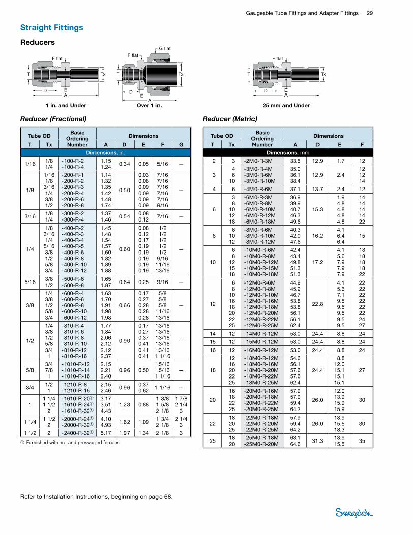
Gaugeable Tube Fittings and Adapter Fittings 29 TUBE
FITTINGS
Reducer (Metric)
AD E
T Tx
F flat
SWAGELOK OVER 1" REDUCER CUTAWAY-MS-01-140 C-PH-0475-DIM
Reducers
➀ Furnished with nut and preswaged ferrules.
1 in. and Under 25 mm and UnderOver 1 in.
Reducer (Fractional)
AD E
T Tx
F flat
A
DE
T Tx
F flat
G flat
Tube OD Basic
Ordering Number
Dimensions
T Tx A D E F G
Dimensions, in.
1/16 1/8 1/4
-100-R-2 -100-R-4
1.15 1.24 0.34 0.05 5/16 —
1/8
1/16 1/8 3/16 1/4 3/8 1/2
-200-R-1 -200-R-2 -200-R-3 -200-R-4 -200-R-6 -200-R-8
1.14 1.32 1.35 1.42 1.48 1.74
0.50
0.03 0.08 0.09 0.09 0.09 0.09
7/16 7/16 7/16 7/16 7/16 9/16
—
3/16 1/8 1/4
-300-R-2 -300-R-4
1.37 1.46 0.54 0.08
0.12 7/16 —
1/4
1/8 3/16 1/4 5/16 3/8 1/2 5/8 3/4
-400-R-2 -400-R-3 -400-R-4 -400-R-5 -400-R-6 -400-R-8 -400-R-10 -400-R-12
1.45 1.48 1.54 1.57 1.60 1.82 1.89 1.88
0.60
0.08 0.12 0.17 0.19 0.19 0.19 0.19 0.19
1/2 1/2 1/2 1/2 1/2 9/16 11/16 13/16
—
5/16 3/8 1/2
-500-R-6 -500-R-8
1.65 1.87 0.64 0.25 9/16 —
3/8
1/4 3/8 1/2 5/8 3/4
-600-R-4 -600-R-6 -600-R-8 -600-R-10 -600-R-12
1.63 1.70 1.91 1.98 1.98
0.66
0.17 0.27 0.28 0.28 0.28
5/8 5/8 5/8
11/16 13/16
—
1/2
1/4 3/8 1/2 5/8 3/4 1
-810-R-4 -810-R-6 -810-R-8 -810-R-10 -810-R-12 -810-R-16
1.77 1.84 2.06 2.12 2.12 2.37
0.90
0.17 0.27 0.37 0.41 0.41 0.41
13/16 13/16 13/16 13/16 13/16 1 1/16
—
5/8 3/4 7/8 1
-1010-R-12 -1010-R-14 -1010-R-16
2.15 2.21 2.40
0.96 0.50 15/16 15/16 1 1/16
—
3/4 1/21
-1210-R-8-1210-R-16
2.152.46 0.96 0.37
0.62 1 1/16 —
1 1 1/4 1 1/2
2
-1610-R-20➀ -1610-R-24➀ -1610-R-32➀
3.17 3.51 4.43
1.23 0.88 1 3/8 1 5/8 2 1/8
1 7/8 2 1/4
3
1 1/4 1 1/2 2
-2000-R-24➀ -2000-R-32➀
4.10 4.93 1.62 1.09 1 3/4
2 1/8 2 1/4
3
1 1/2 2 -2400-R-32➀ 5.17 1.97 1.34 2 1/8 3
Tube OD Basic
Ordering Number
Dimensions
T Tx A D E F
Dimensions, mm 2 3 -2M0-R-3M 33.5 12.9 1.7 12
3 4 6
10
-3M0-R-4M -3M0-R-6M -3M0-R-10M
35.0 36.1 38.4
12.9 2.4 12 12 14
4 6 -4M0-R-6M 37.1 13.7 2.4 12
6
3 8
10 12 18
-6M0-R-3M -6M0-R-8M -6M0-R-10M -6M0-R-12M -6M0-R-18M
36.9 39.9 40.7 46.3 49.6
15.3
1.9 4.8 4.8 4.8 4.8
14 14 14 14 22
8 6
10 12
-8M0-R-6M -8M0-R-10M -8M0-R-12M
40.3 42.0 47.6
16.2 4.1 6.4 6.4
15
10
6 8
12 15 18
-10M0-R-6M -10M0-R-8M -10M0-R-12M -10M0-R-15M -10M0-R-18M
42.4 43.4 49.8 51.3 51.3
17.2
4.1 5.6 7.9 7.9 7.9
18 18 18 18 22
12
6 8
10 16 18 20 22 25
-12M0-R-6M -12M0-R-8M -12M0-R-10M -12M0-R-16M -12M0-R-18M -12M0-R-20M -12M0-R-22M -12M0-R-25M
44.9 45.9 46.7 53.8 53.8 56.1 56.1 62.4
22.8
4.1 5.6 7.1 9.5 9.5 9.5 9.5 9.5
22 22 22 22 22 22 24 27
14 12 -14M0-R-12M 53.0 24.4 8.8 24
15 12 -15M0-R-12M 53.0 24.4 8.8 24
16 12 -16M0-R-12M 53.0 24.4 8.8 24
18
12 16 20 22 25
-18M0-R-12M -18M0-R-16M -18M0-R-20M -18M0-R-22M -18M0-R-25M
54.6 56.1 57.6 57.6 62.4
24.4
8.8 12.0 15.1 15.1 15.1
27
20
16 18 22 25
-20M0-R-16M -20M0-R-18M -20M0-R-22M -20M0-R-25M
57.9 57.9 59.4 64.2
26.0
12.0 13.9 15.9 15.9
30
22 18 20 25
-22M0-R-18M -22M0-R-20M -22M0-R-25M
57.9 59.4 64.2
26.0 13.9 15.5 18.3
30
25 18 20
-25M0-R-18M -25M0-R-20M
63.1 64.6 31.3 13.9
15.5 35
Straight Fittings
Refer to Installation Instructions, beginning on page 68.

30 Tube FittingsTU
BE
FITTI
NGS
Reducers
AD E
T Tx
F flat
AD E
T Tx
F flat
Reducer (Metric to Fractional) Reducer (Fractional to Metric)
Tube OD Basic
Ordering Number
Dimensions
T Tx, mm A D E F
Dimensions, in. 1/8 6 -200-R-6M 1.42 0.50 0.09 7/16
Tube OD Basic
Ordering Number
Dimensions
T Tx, in. A D E F
Dimensions, mm 2 1/8 -2M0-R-2 33.5 12.9 1.7 12
3 1/8 1/4
-3M0-R-2 -3M0-R-4
33.5 36.1 12.9 2.0
2.4 12
4 1/4 -4M0-R-4 37.1 13.7 2.4 12
6
1/8 1/4
5/16 3/8 1/2
-6M0-R-2 -6M0-R-4 -6M0-R-5 -6M0-R-6 -6M0-R-8
36.9 39.2 39.9 40.7 46.3
15.3
2.0 4.4 4.8 4.8 4.8
14
8 1/4 3/8 1/2
-8M0-R-4 -8M0-R-6 -8M0-R-8
40.3 42.0 47.6
16.2 4.4 6.4 6.4
15
10 3/8 1/2
-10M0-R-6 -10M0-R-8
44.2 49.8 17.2 6.8
7.9 18
12 1/2 3/4
-12M0-R-8 -12M0-R-12
52.3 53.8 22.8 9.3
9.5 22
18 3/4 1
-18M0-R-12 -18M0-R-16
56.1 62.4 24.4 14.7
15.1 27
25 1 -25M0-R-16 69.5 31.3 20.2 35
Long Reducer
Use only long reducers in female Swagelok end connections.AD
ET
F flat
Tx
Tube OD Basic
Ordering Number
Dimensions
T Tx A D E F
Dimensions, in. 3/8 1/2 -600-RF-8 2.57 0.66 0.25 5/8
Bulkhead Reducer
AD
E
F flat F flat
Tube OD
Basic Ordering Number
Dimensions
A D E F
Panel Hole Size
Max Panel
Thickness
Dimensions, in. 1/8 -200-R1-2 1.95 0.50 0.08 1/2 21/64 0.50
1/4 -400-R1-4 2.20 0.60 0.17 5/8 29/64 0.40
3/8 -600-R1-6 2.41 0.66 0.27 3/4 37/64 0.44
1/2 -810-R1-8 2.87 0.90 0.37 15/16 49/64 0.50
5/8 -1010-R1-10 2.96 0.96 0.47 1 1/16 57/64 0.50
3/4 -1210-R1-12 3.21 0.96 0.58 1 3/16 1 1/64 0.66
1 -1610-R1-16 3.95 1.23 0.80 1 5/8 1 21/64 0.75
Straight Fittings
Refer to Installation Instructions, beginning on page 68.
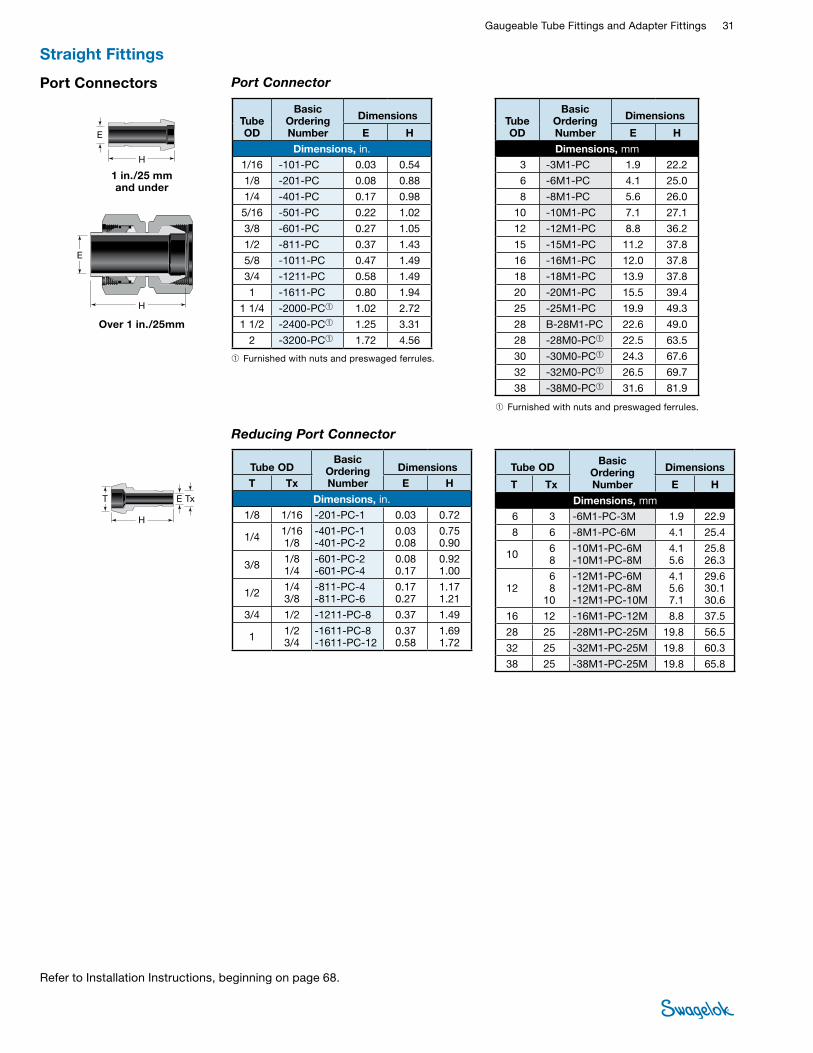
Gaugeable Tube Fittings and Adapter Fittings 31 TUBE
FITTINGSPort Connectors Port Connector
H
E
H
E
➀ Furnished with nuts and preswaged ferrules.
➀ Furnished with nuts and preswaged ferrules.
1 in./25 mm and under
Over 1 in./25mm
Tube OD
Basic Ordering Number
Dimensions
E H
Dimensions, in. 1/16 -101-PC 0.03 0.54
1/8 -201-PC 0.08 0.88
1/4 -401-PC 0.17 0.98
5/16 -501-PC 0.22 1.02
3/8 -601-PC 0.27 1.05
1/2 -811-PC 0.37 1.43
5/8 -1011-PC 0.47 1.49
3/4 -1211-PC 0.58 1.49
1 -1611-PC 0.80 1.94
1 1/4 -2000-PC➀ 1.02 2.72
1 1/2 -2400-PC➀ 1.25 3.31
2 -3200-PC➀ 1.72 4.56
Tube OD
Basic Ordering Number
Dimensions
E H
Dimensions, mm 3 -3M1-PC 1.9 22.2
6 -6M1-PC 4.1 25.0
8 -8M1-PC 5.6 26.0
10 -10M1-PC 7.1 27.1
12 -12M1-PC 8.8 36.2
15 -15M1-PC 11.2 37.8
16 -16M1-PC 12.0 37.8
18 -18M1-PC 13.9 37.8
20 -20M1-PC 15.5 39.4
25 -25M1-PC 19.9 49.3
28 B-28M1-PC 22.6 49.0
28 -28M0-PC➀ 22.5 63.5
30 -30M0-PC➀ 24.3 67.6
32 -32M0-PC➀ 26.5 69.7
38 -38M0-PC➀ 31.6 81.9
Reducing Port Connector
H
T TxE
Tube OD Basic
Ordering Number
Dimensions
T Tx E H
Dimensions, in. 1/8 1/16 -201-PC-1 0.03 0.72
1/4 1/16 1/8
-401-PC-1 -401-PC-2
0.03 0.08
0.75 0.90
3/8 1/8 1/4
-601-PC-2 -601-PC-4
0.08 0.17
0.92 1.00
1/2 1/4 3/8
-811-PC-4 -811-PC-6
0.17 0.27
1.17 1.21
3/4 1/2 -1211-PC-8 0.37 1.49
1 1/2 3/4
-1611-PC-8 -1611-PC-12
0.37 0.58
1.69 1.72
Tube OD Basic
Ordering Number
Dimensions
T Tx E H
Dimensions, mm 6 3 -6M1-PC-3M 1.9 22.9
8 6 -8M1-PC-6M 4.1 25.4
10 6 8
-10M1-PC-6M -10M1-PC-8M
4.1 5.6
25.8 26.3
12 6 8
10
-12M1-PC-6M -12M1-PC-8M -12M1-PC-10M
4.1 5.6 7.1
29.6 30.1 30.6
16 12 -16M1-PC-12M 8.8 37.5
28 25 -28M1-PC-25M 19.8 56.5
32 25 -32M1-PC-25M 19.8 60.3
38 25 -38M1-PC-25M 19.8 65.8
Straight Fittings
Refer to Installation Instructions, beginning on page 68.
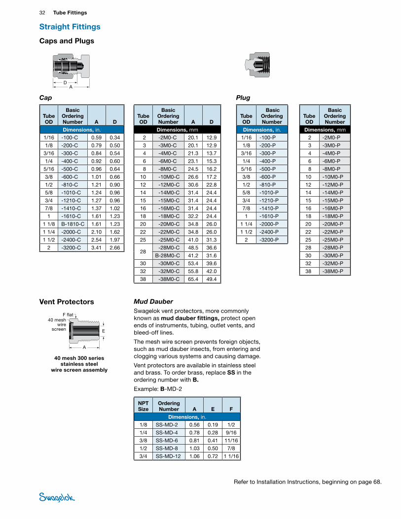
32 Tube FittingsTU
BE
FITTI
NGS
Caps and Plugs
Cap Plug
AD
Tube OD
Basic Ordering Number A D
Dimensions, in. 1/16 -100-C 0.59 0.34
1/8 -200-C 0.79 0.50
3/16 -300-C 0.84 0.54
1/4 -400-C 0.92 0.60
5/16 -500-C 0.96 0.64
3/8 -600-C 1.01 0.66
1/2 -810-C 1.21 0.90
5/8 -1010-C 1.24 0.96
3/4 -1210-C 1.27 0.96
7/8 -1410-C 1.37 1.02
1 -1610-C 1.61 1.23
1 1/8 B-1810-C 1.61 1.23
1 1/4 -2000-C 2.10 1.62
1 1/2 -2400-C 2.54 1.97
2 -3200-C 3.41 2.66
Tube OD
Basic Ordering Number A D
Dimensions, mm 2 -2M0-C 20.1 12.9
3 -3M0-C 20.1 12.9
4 -4M0-C 21.3 13.7
6 -6M0-C 23.1 15.3
8 -8M0-C 24.5 16.2
10 -10M0-C 26.6 17.2
12 -12M0-C 30.6 22.8
14 -14M0-C 31.4 24.4
15 -15M0-C 31.4 24.4
16 -16M0-C 31.4 24.4
18 -18M0-C 32.2 24.4
20 -20M0-C 34.8 26.0
22 -22M0-C 34.8 26.0
25 -25M0-C 41.0 31.3
28 -28M0-C 48.5 36.6
B-28M0-C 41.2 31.6
30 -30M0-C 53.4 39.6
32 -32M0-C 55.8 42.0
38 -38M0-C 65.4 49.4
Tube OD
Basic Ordering Number
Dimensions, in. 1/16 -100-P
1/8 -200-P
3/16 -300-P
1/4 -400-P
5/16 -500-P
3/8 -600-P
1/2 -810-P
5/8 -1010-P
3/4 -1210-P
7/8 -1410-P
1 -1610-P
1 1/4 -2000-P
1 1/2 -2400-P
2 -3200-P
Tube OD
Basic Ordering Number
Dimensions, mm 2 -2M0-P
3 -3M0-P
4 -4M0-P
6 -6M0-P
8 -8M0-P
10 -10M0-P
12 -12M0-P
14 -14M0-P
15 -15M0-P
16 -16M0-P
18 -18M0-P
20 -20M0-P
22 -22M0-P
25 -25M0-P
28 -28M0-P
30 -30M0-P
32 -32M0-P
38 -38M0-P
40 mesh 300 series stainless steel
wire screen assembly
Vent Protectors Mud DauberSwagelok vent protectors, more commonly known as mud dauber fittings, protect open ends of instruments, tubing, outlet vents, and bleed-off lines.
The mesh wire screen prevents foreign objects, such as mud dauber insects, from entering and clogging various systems and causing damage.
Vent protectors are available in stainless steel and brass. To order brass, replace SS in the ordering number with B.
Example: B-MD-2
40 mesh wire
screen
A
E
F flat
NPT Size
Ordering Number A E F
Dimensions, in. 1/8 SS-MD-2 0.56 0.19 1/2
1/4 SS-MD-4 0.78 0.28 9/16
3/8 SS-MD-6 0.81 0.41 11/16
1/2 SS-MD-8 1.03 0.50 7/8
3/4 SS-MD-12 1.06 0.72 1 1/16
Straight Fittings
Refer to Installation Instructions, beginning on page 68.
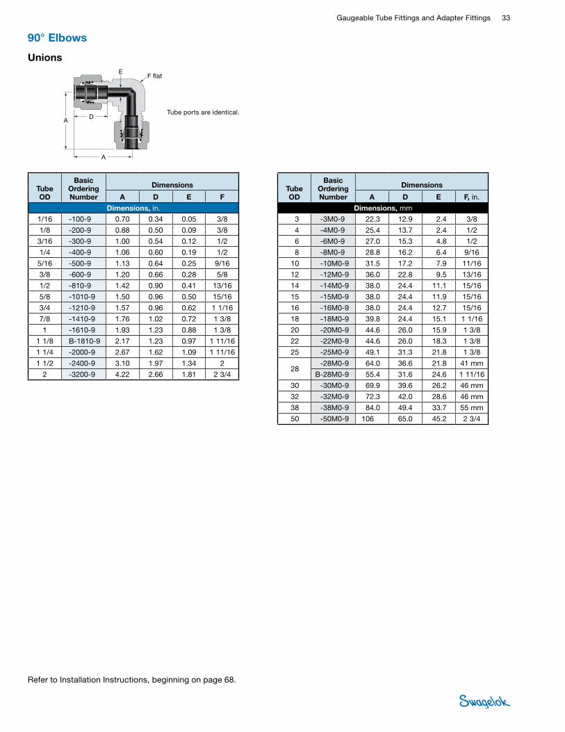
Gaugeable Tube Fittings and Adapter Fittings 33 TUBE
FITTINGS
90° Elbows
Unions
Tube ports are identical.D
A
A
EF flat
Tube OD
Basic Ordering Number
Dimensions
A D E F
Dimensions, in. 1/16 -100-9 0.70 0.34 0.05 3/8
1/8 -200-9 0.88 0.50 0.09 3/8
3/16 -300-9 1.00 0.54 0.12 1/2
1/4 -400-9 1.06 0.60 0.19 1/2
5/16 -500-9 1.13 0.64 0.25 9/16
3/8 -600-9 1.20 0.66 0.28 5/8
1/2 -810-9 1.42 0.90 0.41 13/16
5/8 -1010-9 1.50 0.96 0.50 15/16
3/4 -1210-9 1.57 0.96 0.62 1 1/16
7/8 -1410-9 1.76 1.02 0.72 1 3/8
1 -1610-9 1.93 1.23 0.88 1 3/8
1 1/8 B-1810-9 2.17 1.23 0.97 1 11/16
1 1/4 -2000-9 2.67 1.62 1.09 1 11/16
1 1/2 -2400-9 3.10 1.97 1.34 2
2 -3200-9 4.22 2.66 1.81 2 3/4
Tube OD
Basic Ordering Number
Dimensions
A D E F, in.
Dimensions, mm 3 -3M0-9 22.3 12.9 2.4 3/8
4 -4M0-9 25.4 13.7 2.4 1/2
6 -6M0-9 27.0 15.3 4.8 1/2
8 -8M0-9 28.8 16.2 6.4 9/16
10 -10M0-9 31.5 17.2 7.9 11/16
12 -12M0-9 36.0 22.8 9.5 13/16
14 -14M0-9 38.0 24.4 11.1 15/16
15 -15M0-9 38.0 24.4 11.9 15/16
16 -16M0-9 38.0 24.4 12.7 15/16
18 -18M0-9 39.8 24.4 15.1 1 1/16
20 -20M0-9 44.6 26.0 15.9 1 3/8
22 -22M0-9 44.6 26.0 18.3 1 3/8
25 -25M0-9 49.1 31.3 21.8 1 3/8
28 -28M0-9 64.0 36.6 21.8 41 mm
B-28M0-9 55.4 31.6 24.6 1 11/16
30 -30M0-9 69.9 39.6 26.2 46 mm
32 -32M0-9 72.3 42.0 28.6 46 mm
38 -38M0-9 84.0 49.4 33.7 55 mm
50 -50M0-9 106 65.0 45.2 2 3/4
Refer to Installation Instructions, beginning on page 68.
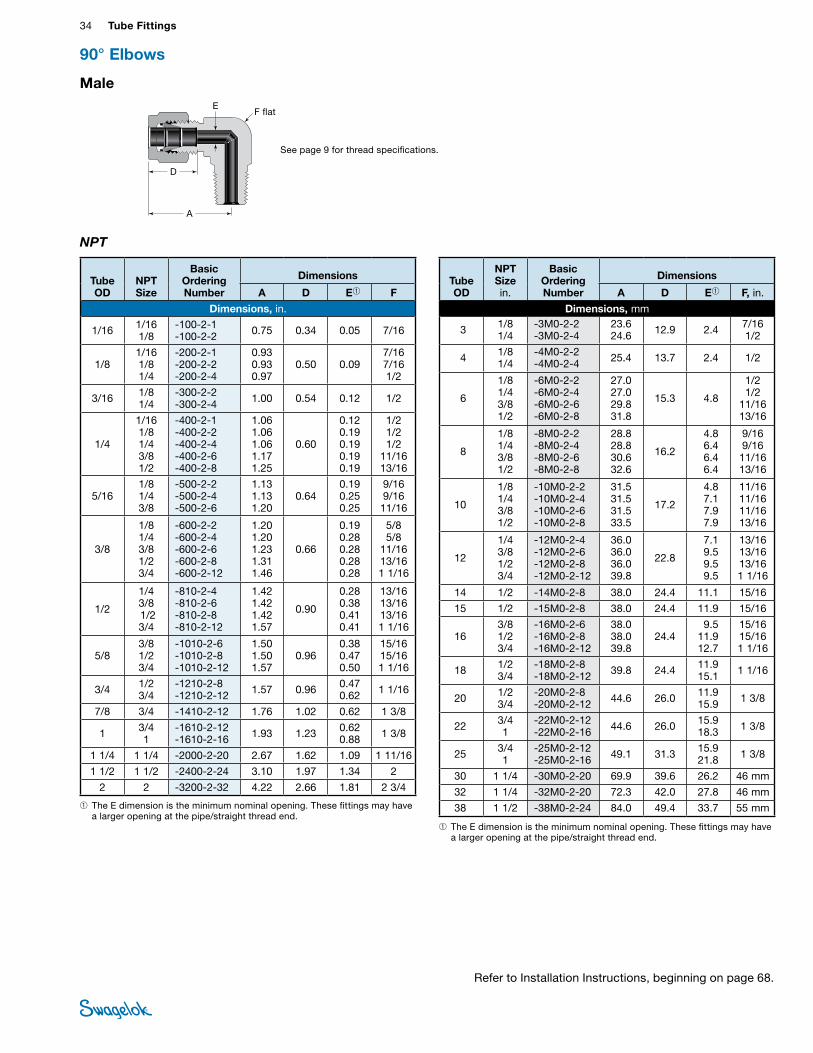
34 Tube FittingsTU
BE
FITTI
NGS
Male
NPT
D
A
EF flat
➀ The E dimension is the minimum nominal opening. These fittings may have a larger opening at the pipe/straight thread end.
➀ The E dimension is the minimum nominal opening. These fittings may have a larger opening at the pipe/straight thread end.
Tube OD
NPT Size
Basic Ordering Number
Dimensions
A D E➀ F
Dimensions, in.
1/16 1/16 1/8
-100-2-1 -100-2-2 0.75 0.34 0.05 7/16
1/8 1/16 1/8 1/4
-200-2-1 -200-2-2 -200-2-4
0.93 0.93 0.97
0.50
0.09
7/16 7/16 1/2
3/16 1/8 1/4
-300-2-2 -300-2-4 1.00 0.54 0.12 1/2
1/4
1/16 1/8 1/4 3/8 1/2
-400-2-1 -400-2-2 -400-2-4 -400-2-6 -400-2-8
1.06 1.06 1.06 1.17 1.25
0.60
0.12 0.19 0.19 0.19 0.19
1/2 1/2 1/2
11/16 13/16
5/16 1/8 1/4 3/8
-500-2-2 -500-2-4 -500-2-6
1.13 1.13 1.20
0.64 0.19 0.25 0.25
9/16 9/16 11/16
3/8
1/8 1/4 3/8 1/2 3/4
-600-2-2 -600-2-4 -600-2-6 -600-2-8 -600-2-12
1.20 1.20 1.23 1.31 1.46
0.66
0.19 0.28 0.28 0.28 0.28
5/8 5/8
11/16 13/16 1 1/16
1/2
1/4 3/8 1/2 3/4
-810-2-4 -810-2-6 -810-2-8 -810-2-12
1.42 1.42 1.42 1.57
0.90
0.28 0.38 0.41 0.41
13/16 13/16 13/16 1 1/16
5/8 3/8 1/2 3/4
-1010-2-6 -1010-2-8 -1010-2-12
1.50 1.50 1.57
0.96 0.38 0.47 0.50
15/16 15/16 1 1/16
3/4 1/2 3/4
-1210-2-8 -1210-2-12 1.57 0.96 0.47
0.62 1 1/16
7/8 3/4 -1410-2-12 1.76 1.02 0.62 1 3/8
1 3/4 1
-1610-2-12 -1610-2-16 1.93 1.23 0.62
0.88 1 3/8
1 1/4 1 1/4 -2000-2-20 2.67 1.62 1.09 1 11/16
1 1/2 1 1/2 -2400-2-24 3.10 1.97 1.34 2
2 2 -3200-2-32 4.22 2.66 1.81 2 3/4
Tube OD
NPT Size in.
Basic Ordering Number
Dimensions
A D E➀ F, in.
Dimensions, mm
3 1/8 1/4
-3M0-2-2 -3M0-2-4
23.6 24.6 12.9 2.4 7/16
1/2
4 1/8 1/4
-4M0-2-2 -4M0-2-4 25.4 13.7 2.4 1/2
6
1/8 1/4 3/8 1/2
-6M0-2-2 -6M0-2-4 -6M0-2-6 -6M0-2-8
27.0 27.0 29.8 31.8
15.3 4.8
1/2 1/2
11/16 13/16
8
1/8 1/4 3/8 1/2
-8M0-2-2 -8M0-2-4 -8M0-2-6 -8M0-2-8
28.8 28.8 30.6 32.6
16.2
4.8 6.4 6.4 6.4
9/16 9/16 11/16 13/16
10
1/8 1/4 3/8 1/2
-10M0-2-2 -10M0-2-4 -10M0-2-6 -10M0-2-8
31.5 31.5 31.5 33.5
17.2
4.8 7.1 7.9 7.9
11/16 11/16 11/16 13/16
12
1/4 3/8 1/2 3/4
-12M0-2-4 -12M0-2-6 -12M0-2-8 -12M0-2-12
36.0 36.0 36.0 39.8
22.8
7.1 9.5 9.5 9.5
13/16 13/16 13/16 1 1/16
14 1/2 -14M0-2-8 38.0 24.4 11.1 15/16
15 1/2 -15M0-2-8 38.0 24.4 11.9 15/16
16 3/8 1/2 3/4
-16M0-2-6 -16M0-2-8 -16M0-2-12
38.0 38.0 39.8
24.4 9.5
11.9 12.7
15/16 15/16 1 1/16
18 1/2 3/4
-18M0-2-8 -18M0-2-12 39.8 24.4 11.9
15.1 1 1/16
20 1/2 3/4
-20M0-2-8 -20M0-2-12 44.6 26.0 11.9
15.9 1 3/8
22 3/4 1
-22M0-2-12 -22M0-2-16 44.6 26.0 15.9
18.3 1 3/8
25 3/4 1
-25M0-2-12 -25M0-2-16 49.1 31.3 15.9
21.8 1 3/8
30 1 1/4 -30M0-2-20 69.9 39.6 26.2 46 mm
32 1 1/4 -32M0-2-20 72.3 42.0 27.8 46 mm
38 1 1/2 -38M0-2-24 84.0 49.4 33.7 55 mm
90° Elbows
See page 9 for thread specifications.
Refer to Installation Instructions, beginning on page 68.
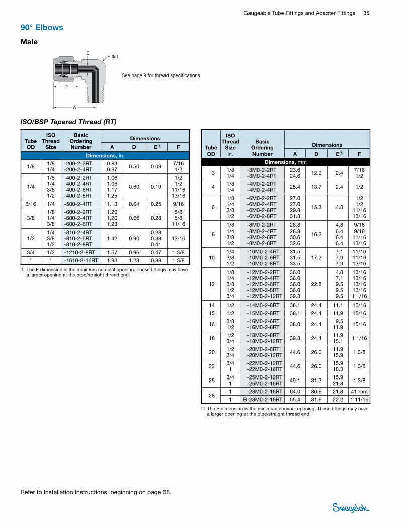
Gaugeable Tube Fittings and Adapter Fittings 35 TUBE
FITTINGS
See page 9 for thread specifications.
Male
ISO/BSP Tapered Thread (RT)
D
A
EF flat
➀ The E dimension is the minimum nominal opening. These fittings may have a larger opening at the pipe/straight thread end.
➀ The E dimension is the minimum nominal opening. These fittings may have a larger opening at the pipe/straight thread end.
Tube OD
ISO Thread
Size
Basic Ordering Number
Dimensions
A D E➀ F
Dimensions, in.
1/8 1/8 1/4
-200-2-2RT -200-2-4RT
0.83 0.97 0.50 0.09 7/16
1/2
1/4
1/8 1/4 3/8 1/2
-400-2-2RT -400-2-4RT -400-2-6RT -400-2-8RT
1.06 1.06 1.17 1.25
0.60 0.19
1/2 1/2
11/16 13/16
5/16 1/4 -500-2-4RT 1.13 0.64 0.25 9/16
3/8 1/8 1/4 3/8
-600-2-2RT -600-2-4RT -600-2-6RT
1.20 1.20 1.23
0.66 0.28 5/8 5/8
11/16
1/2 1/4 3/8 1/2
-810-2-4RT -810-2-6RT -810-2-8RT
1.42 0.90 0.28 0.38 0.41
13/16
3/4 1/2 -1210-2-8RT 1.57 0.96 0.47 1 3/8
1 1 -1610-2-16RT 1.93 1.23 0.88 1 3/8
Tube OD
ISO Thread
Size in.
Basic Ordering Number
Dimensions
A D E➀ F
Dimensions, mm
3 1/8 1/4
-3M0-2-2RT -3M0-2-4RT
23.6 24.6 12.9 2.4 7/16
1/2
4 1/8 1/4
-4M0-2-2RT -4M0-2-4RT 25.4 13.7 2.4 1/2
6
1/8 1/4 3/8 1/2
-6M0-2-2RT -6M0-2-4RT -6M0-2-6RT -6M0-2-8RT
27.0 27.0 29.8 31.8
15.3 4.8
1/2 1/2
11/16 13/16
8
1/8 1/4 3/8 1/2
-8M0-2-2RT -8M0-2-4RT -8M0-2-6RT -8M0-2-8RT
28.8 28.8 30.6 32.6
16.2
4.8 6.4 6.4 6.4
9/16 9/16 11/16 13/16
10 1/4 3/8 1/2
-10M0-2-4RT -10M0-2-6RT -10M0-2-8RT
31.5 31.5 33.5
17.2 7.1 7.9 7.9
11/16 11/16 13/16
12
1/8 1/4 3/8 1/2 3/4
-12M0-2-2RT -12M0-2-4RT -12M0-2-6RT -12M0-2-8RT -12M0-2-12RT
36.0 36.0 36.0 36.0 39.8
22.8
4.8 7.1 9.5 9.5 9.5
13/16 13/16 13/16 13/16 1 1/16
14 1/2 -14M0-2-8RT 38.1 24.4 11.1 15/16
15 1/2 -15M0-2-8RT 38.1 24.4 11.9 15/16
16 3/8 1/2
-16M0-2-6RT -16M0-2-8RT 38.0 24.4 9.5
11.9 15/16
18 1/2 3/4
-18M0-2-8RT -18M0-2-12RT 39.8 24.4 11.9
15.1 1 1/16
20 1/2 3/4
-20M0-2-8RT -20M0-2-12RT 44.6 26.0 11.9
15.9 1 3/8
22 3/4 1
-22M0-2-12RT -22M0-2-16RT 44.6 26.0 15.9
18.3 1 3/8
25 3/4 1
-25M0-2-12RT -25M0-2-16RT 49.1 31.3 15.9
21.8 1 3/8
28 1 -28M0-2-16RT 64.0 36.6 21.8 41 mm
1 B-28M0-2-16RT 55.4 31.6 22.2 1 11/16
90° Elbows
Refer to Installation Instructions, beginning on page 68.
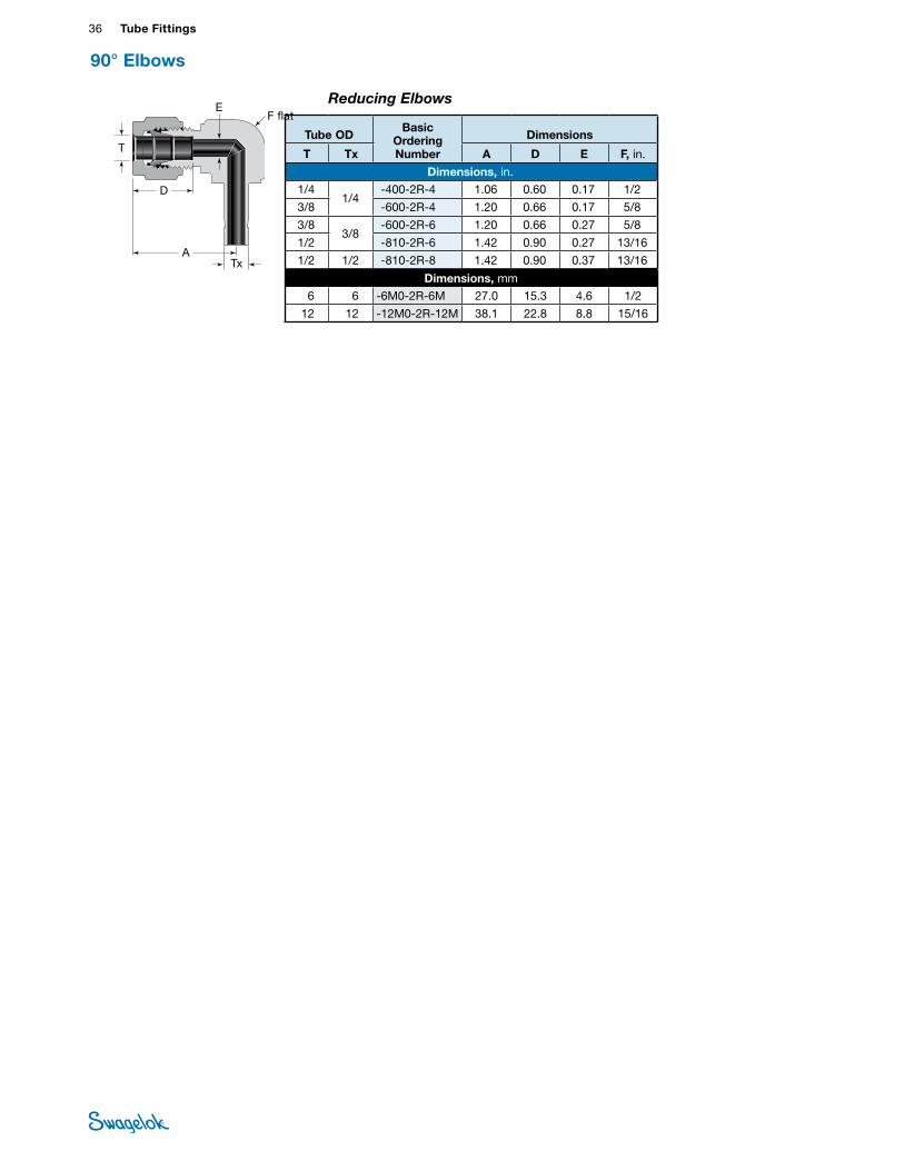
36 Tube FittingsTU
BE
FITTI
NGS
90° Elbows
Reducing Elbows
Tube OD Basic
OrderingNumber
Dimensions
T Tx A D E F, in.
Dimensions, in.
1/41/4
-400-2R-4 1.06 0.60 0.17 1/2
3/8 -600-2R-4 1.20 0.66 0.17 5/8
3/83/8
-600-2R-6 1.20 0.66 0.27 5/8
1/2 -810-2R-6 1.42 0.90 0.27 13/16
1/2 1/2 -810-2R-8 1.42 0.90 0.37 13/16
Dimensions, mm
6 6 -6M0-2R-6M 27.0 15.3 4.6 1/2
12 12 -12M0-2R-12M 38.1 22.8 8.8 15/16
EF flat
D
ATx
T
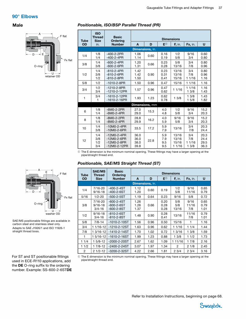
Gaugeable Tube Fittings and Adapter Fittings 37 TUBE
FITTINGSMale Positionable, ISO/BSP Parallel Thread (PR)
O-ring
D
A
E
F flat
Fx flat
➀ The E dimension is the minimum nominal opening. These fittings may have a larger opening at the pipe/straight thread end.
Tube OD
ISO Thread
Size in.
Basic Ordering Number
Dimensions
A D E➀ F, in. Fx, in. U
Dimensions, in.
1/4 1/8 1/4
-400-2-2PR -400-2-4PR
1.06 1.14 0.60 0.16
0.19 1/2 5/8
9/16 3/4
0.60 0.80
3/8 1/4 3/8
-600-2-4PR -600-2-6PR
1.20 1.31 0.66 0.23
0.28 5/8
13/16 3/4 7/8
0.80 0.96
1/2 1/4 3/8 1/2
-810-2-4PR -810-2-6PR -810-2-8PR
1.42 1.42 1.50
0.90 0.23 0.31 0.41
13/16 13/16 15/16
3/4 7/8
1 1/16
0.80 0.96 1.16
5/8 1/2 -1010-2-8PR 1.50 0.96 0.47 15/16 1 1/16 1.16
3/4 1/2 3/4
-1210-2-8PR -1210-2-12PR 1.57 0.96 0.47
0.62 1 1/16 1 1/16 1 3/8
1.16 1.43
1 3/4 1
-1610-2-12PR -1610-2-16PR 1.93 1.23 0.62
0.78 1 3/8 1 3/8 1 5/8
1.43 1.82
Dimensions, mm
6 1/8 1/4
-6M0-2-2PR -6M0-2-4PR
27.0 29.0 15.3 4.0
4.8 1/2 5/8
9/16 3/4
15.2 20.3
8 1/8 1/4
-8M0-2-2PR -8M0-2-4PR
28.8 29.9 16.2 4.0
5.9 9/16 5/8
9/16 3/4
15.2 20.3
10 1/4 3/8
-10M0-2-4PR -10M0-2-6PR 33.5 17.2 5.9
7.9 13/16 3/4 7/8
20.3 24.4
12
1/4 3/8 1/2 3/4
-12M0-2-4PR -12M0-2-6PR -12M0-2-8PR -12M0-2-12PR
36.0 36.0 38.0 39.8
22.8
5.9 7.9 9.5 9.5
13/16 13/16 15/16 1 1/16
3/4 7/8
1 1/16 1 3/8
20.3 24.4 29.5 36.3
Positionable, SAE/MS Straight Thread (ST)
O-ring
U washer OD
SAE/MS positionable fittings are available in carbon steel and stainless steel only.Adapts to SAE J1926/1 and ISO 11926-1 straight thread boss.
D
AE F flat
Fx flat
➀ The E dimension is the minimum nominal opening. These fittings may have a larger opening at the pipe/straight thread end.
Tube OD
SAE/MS Thread
Size
Basic Ordering Number
Dimensions
A D E➀ F, in. Fx, in. U
Dimensions, in.
1/4 7/16-20 9/16-18
-400-2-4ST -400-2-6ST
1.12 1.20 0.60 0.19 1/2
5/8 9/16 11/16
0.65 0.79
5/16 1/2-20 -500-2-5ST 1.19 0.64 0.23 9/16 5/8 0.72
3/8 7/16-20 9/16-18 3/4-16
-600-2-4ST -600-2-6ST -600-2-8ST
1.26 1.26 1.37
0.66 0.20 0.28 0.28
5/8 5/8
13/16
9/16 11/16 7/8
0.65 0.79 1.01
1/2 9/16-18 3/4-16
-810-2-6ST -810-2-8ST 1.48 0.90 0.28
0.41 13/16 11/16 7/8
0.79 1.01
5/8 7/8-14 -1010-2-10ST 1.56 0.96 0.50 15/16 1 1.16
3/4 1 1/16-12 -1210-2-12ST 1.63 0.96 0.62 1 1/16 1 1/4 1.44
7/8 1 3/16-12 -1410-2-14ST 1.70 1.02 0.72 1 3/16 1 3/8 1.59
1 1 5/16-12 -1610-2-16ST 1.99 1.23 0.88 1 3/8 1 1/2 1.73
1 1/4 1 5/8-12 -2000-2-20ST 2.67 1.62 1.09 1 11/16 1 7/8 2.16
1 1/2 1 7/8-12 -2400-2-24ST 3.07 1.97 1.34 2 2 1/8 2.45
2 2 1/2-12 -3200-2-32ST 4.22 2.66 1.81 2 3/4 2 3/4 3.16
U retainer OD
90° Elbows
Refer to Installation Instructions, beginning on page 68.
For ST and ST positionable fittings used in ECE-R110 applications, add the DE O-ring suffix to the ordering number. Example: SS-600-2-6STDE
Tube OD Basic
OrderingNumber
Dimensions
T Tx A D E F, in.
Dimensions, in.
1/41/4
-400-2R-4 1.06 0.60 0.17 1/2
3/8 -600-2R-4 1.20 0.66 0.17 5/8
3/83/8
-600-2R-6 1.20 0.66 0.27 5/8
1/2 -810-2R-6 1.42 0.90 0.27 13/16
1/2 1/2 -810-2R-8 1.42 0.90 0.37 13/16
Dimensions, mm
6 6 -6M0-2R-6M 27.0 15.3 4.6 1/2
12 12 -12M0-2R-12M 38.1 22.8 8.8 15/16

38 Tube FittingsTU
BE
FITTI
NGS
NPT
Female
D
A
EF flat
Male Pipe Weld
D
J
AE
F flat
37.5°
➀ The E dimension is the minimum nominal opening. These fittings may have a larger opening at the weld end. Wall thickness at the weld end is based on schedule 80 pipe.
Weld Tube Socket Weld
DB
A
K
E F flat Tube OD
Socket WeldSize
Basic OrderingNumber
Dimensions
A B D E F K
Dimensions, in. 1/4 1/4 -400-9-4W 1.06 0.28 0.60 0.19 1/2 0.50
3/8 3/8 -600-9-6W 1.20 0.31 0.66 0.28 5/8 0.63
1/2 1/2 -810-9-8W 1.42 0.38 0.90 0.41 13/16 0.81
3/4 3/4 -1210-9-12W 1.57 0.44 0.96 0.62 1 1/16 1.06
1 1 -1610-9-16W 1.93 0.62 1.23 0.88 1 3/8 1.38
Tube OD
Pipe Weld Size
Basic Ordering Number
Dimensions
A D E➀ F J
Dimensions, in.
1/4 1/8 1/4
-400-2-2W -400-2-4W 1.06 0.60 0.19 1/2 0.405
0.540
3/8 1/4 -600-2-4W 1.20 0.66 0.28 5/8 0.540
1/2 1/2 -810-2-8W 1.42 0.90 0.41 13/16 0.840
3/4 3/4 -1210-2-12W 1.57 0.96 0.62 1 1/16 1.050
Tube OD
NPT Size
Basic OrderingNumber
Dimensions
A D E F
Dimensions, in.
1/8 1/8 1/4
-200-8-2 -200-8-4
0.971.08 0.50 0.09 1/2
11/16
3/16 1/8 -300-8-2 1.00 0.54 0.12 1/2
1/4
1/8 1/4 3/8 1/2
-400-8-2 -400-8-4 -400-8-6 -400-8-8
1.06 1.17 1.25 1.36
0.60 0.19
1/2 11/16 13/16
1
5/16 1/8 1/4
-500-8-2 -500-8-4
1.13 1.20 0.64 0.25 9/16
11/16
3/8
1/8 1/4 3/8 1/2
-600-8-2 -600-8-4 -600-8-6 -600-8-8
1.20 1.23 1.31 1.42
0.66 0.28
5/8 11/16 13/16
1
1/2 1/4 3/8 1/2
-810-8-4 -810-8-6 -810-8-8
1.42 1.42 1.53
0.90 0.41 13/1613/16
1
5/8 3/8 1/2
-1010-8-6 -1010-8-8
1.50 1.57 0.96 0.50 15/16
1 1/16
3/4 1/2 3/4
-1210-8-8 -1210-8-12
1.57 1.76 0.96 0.62 1 1/16
1 3/8
7/8 3/4 -1410-8-12 1.76 1.02 0.72 1 3/8
1 3/4 1
-1610-8-12 -1610-8-16
1.93 2.11 1.23 0.88 1 3/8
1 11/16
Tube OD
NPT Size in.
Basic OrderingNumber
Dimensions
A D E F, in.
Dimensions, mm
6 1/8 1/4 1/2
-6M0-8-2 -6M0-8-4 -6M0-8-8
27.0 29.8 34.6
15.3 4.8 1/2
11/16 1
8 1/4 -8M0-8-4 30.6 16.2 6.4 11/16
10 1/8 1/4
-10M0-8-2 -10M0-8-4
31.5 33.5 17.2 7.9 11/16
13/16
12 1/4 1/2
-12M0-8-4 -12M0-8-8
36.0 38.8 22.8 9.5 13/16
1
16 1/2 -16M0-8-8 39.5 24.4 12.7 1 1/16
90° Elbows
Refer to Installation Instructions, beginning on page 68.

Gaugeable Tube Fittings and Adapter Fittings 39 TUBE
FITTINGS
Positionable, SAE/MS Straight Thread (ST)
45° Elbows
Male NPT
➀ The E dimension is the minimum nominal opening. These fittings may have a larger opening at the pipe/straight thread end.
D
A
E
F flat
D
A
E
F flat
O-ring
➀ The E dimension is the minimum nominal opening. These fittings may have a larger opening at the pipe/straight thread end.
Tube OD
NPT Size
Basic OrderingNumber
Dimensions
A D E➀ F
Dimensions, in.
1/4 1/8 1/4
-400-5-2 -400-5-4 0.97 0.60 0.19 1/2
3/8 1/8 1/4 3/8
-600-5-2 -600-5-4 -600-5-6
1.10 1.10 1.15
0.66 0.19 0.28 0.28
5/8 5/8
13/16
1/2 3/8 1/2
-810-5-6 -810-5-8 1.26 0.90 0.38
0.41 13/16
3/4 3/4 -1210-5-12 1.33 0.96 0.62 1 1/16
1 1 -1610-5-16 1.59 1.23 0.88 1 3/8
Tube OD
SAE/MS Thread
Size
Basic OrderingNumber
Dimensions
A D E➀ F U
Dimensions, in. 1/4 7/16-20 -400-5-4ST 1.01 0.60 0.19 1/2 0.65
3/8 9/16-18 -600-5-6ST 1.10 0.66 0.28 5/8 0.79
1/2 3/4-16 -810-5-8ST 1.26 0.90 0.41 13/16 1.01
3/4 1 1/16-12 -1210-5-12ST 1.33 0.96 0.62 1 1/16 1.44
1 1 5/16-12 -1610-5-16ST 1.59 1.23 0.88 1 3/8 1.73
SAE/MS positionable fittings are available in carbon steel and stainless steel only.Adapts to SAE J1926/1 and ISO 11926-1 straight thread boss.
U
washe
r OD
Refer to Installation Instructions, beginning on page 68.
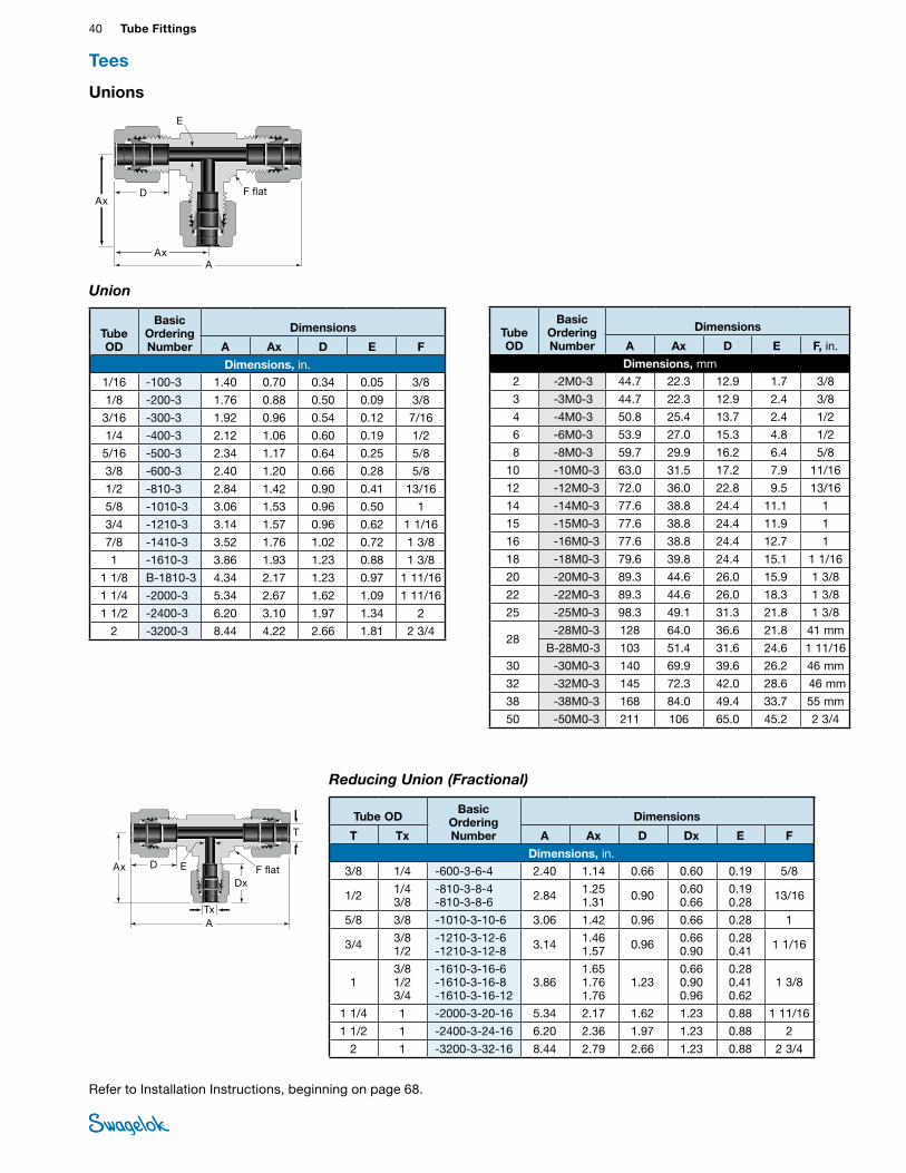
40 Tube FittingsTU
BE
FITTI
NGS
Reducing Union (Fractional)
Tees
Unions
Union
D
AAx
Ax
E
F flat
D
Dx
ATx
T
Ax E F flat
Tube OD
Basic Ordering Number
Dimensions
A Ax D E F
Dimensions, in. 1/16 -100-3 1.40 0.70 0.34 0.05 3/8
1/8 -200-3 1.76 0.88 0.50 0.09 3/8
3/16 -300-3 1.92 0.96 0.54 0.12 7/16
1/4 -400-3 2.12 1.06 0.60 0.19 1/2
5/16 -500-3 2.34 1.17 0.64 0.25 5/8
3/8 -600-3 2.40 1.20 0.66 0.28 5/8
1/2 -810-3 2.84 1.42 0.90 0.41 13/16
5/8 -1010-3 3.06 1.53 0.96 0.50 1
3/4 -1210-3 3.14 1.57 0.96 0.62 1 1/16
7/8 -1410-3 3.52 1.76 1.02 0.72 1 3/8
1 -1610-3 3.86 1.93 1.23 0.88 1 3/8
1 1/8 B-1810-3 4.34 2.17 1.23 0.97 1 11/16
1 1/4 -2000-3 5.34 2.67 1.62 1.09 1 11/16
1 1/2 -2400-3 6.20 3.10 1.97 1.34 2
2 -3200-3 8.44 4.22 2.66 1.81 2 3/4
Tube OD
Basic Ordering Number
Dimensions
A Ax D E F, in.
Dimensions, mm 2 -2M0-3 44.7 22.3 12.9 1.7 3/8
3 -3M0-3 44.7 22.3 12.9 2.4 3/8
4 -4M0-3 50.8 25.4 13.7 2.4 1/2
6 -6M0-3 53.9 27.0 15.3 4.8 1/2
8 -8M0-3 59.7 29.9 16.2 6.4 5/8
10 -10M0-3 63.0 31.5 17.2 7.9 11/16
12 -12M0-3 72.0 36.0 22.8 9.5 13/16
14 -14M0-3 77.6 38.8 24.4 11.1 1
15 -15M0-3 77.6 38.8 24.4 11.9 1
16 -16M0-3 77.6 38.8 24.4 12.7 1
18 -18M0-3 79.6 39.8 24.4 15.1 1 1/16
20 -20M0-3 89.3 44.6 26.0 15.9 1 3/8
22 -22M0-3 89.3 44.6 26.0 18.3 1 3/8
25 -25M0-3 98.3 49.1 31.3 21.8 1 3/8
28 -28M0-3 128 64.0 36.6 21.8 41 mm
B-28M0-3 103 51.4 31.6 24.6 1 11/16
30 -30M0-3 140 69.9 39.6 26.2 46 mm
32 -32M0-3 145 72.3 42.0 28.6 46 mm
38 -38M0-3 168 84.0 49.4 33.7 55 mm
50 -50M0-3 211 106 65.0 45.2 2 3/4
Tube OD Basic
Ordering Number
Dimensions
T Tx A Ax D Dx E F
Dimensions, in. 3/8 1/4 -600-3-6-4 2.40 1.14 0.66 0.60 0.19 5/8
1/2 1/4 3/8
-810-3-8-4 -810-3-8-6 2.84 1.25
1.31 0.90 0.60 0.66
0.19 0.28 13/16
5/8 3/8 -1010-3-10-6 3.06 1.42 0.96 0.66 0.28 1
3/4 3/8 1/2
-1210-3-12-6 -1210-3-12-8 3.14 1.46
1.57 0.96 0.66 0.90
0.28 0.41 1 1/16
1 3/8 1/2 3/4
-1610-3-16-6 -1610-3-16-8 -1610-3-16-12
3.86 1.65 1.76 1.76
1.23 0.66 0.90 0.96
0.28 0.41 0.62
1 3/8
1 1/4 1 -2000-3-20-16 5.34 2.17 1.62 1.23 0.88 1 11/16
1 1/2 1 -2400-3-24-16 6.20 2.36 1.97 1.23 0.88 2
2 1 -3200-3-32-16 8.44 2.79 2.66 1.23 0.88 2 3/4
Refer to Installation Instructions, beginning on page 68.
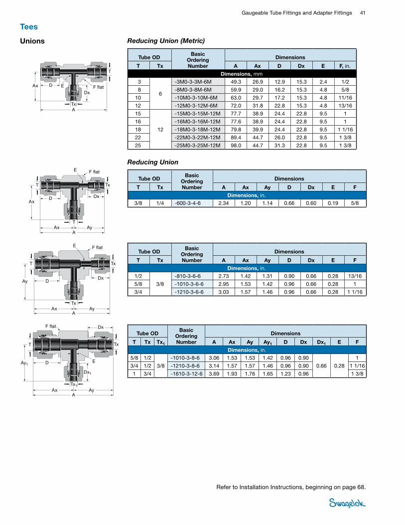
Gaugeable Tube Fittings and Adapter Fittings 41 TUBE
FITTINGS
Reducing Union (Metric)
D
Dx
ATx
T
Ax E F flat
Tube OD Basic
Ordering Number
Dimensions
T Tx A Ax D Dx E F, in.
Dimensions, mm 3
6
-3M0-3-3M-6M 49.3 26.9 12.9 15.3 2.4 1/2
8 -8M0-3-8M-6M 59.9 29.0 16.2 15.3 4.8 5/8
10 -10M0-3-10M-6M 63.0 29.7 17.2 15.3 4.8 11/16
12 -12M0-3-12M-6M 72.0 31.8 22.8 15.3 4.8 13/16
15
12
-15M0-3-15M-12M 77.7 38.9 24.4 22.8 9.5 1
16 -16M0-3-16M-12M 77.6 38.9 24.4 22.8 9.5 1
18 -18M0-3-18M-12M 79.8 39.9 24.4 22.8 9.5 1 1/16
22 -22M0-3-22M-12M 89.4 44.7 26.0 22.8 9.5 1 3/8
25 -25M0-3-25M-12M 98.0 44.7 31.3 22.8 9.5 1 3/8
Reducing Union
D Dx
AAx Ay
Ax
E F flat
TxT
T
Tube OD Basic
Ordering Number
Dimensions
T Tx A Ax Ay D Dx E F
Dimensions, in. 3/8 1/4 -600-3-4-6 2.34 1.20 1.14 0.66 0.60 0.19 5/8
DDx
AAx Ay
Ay
E F flat
TxT
Tx
Tube OD Basic
Ordering Number
Dimensions
T Tx A Ax Ay D Dx E F
Dimensions, in. 1/2
3/8
-810-3-6-6 2.73 1.42 1.31 0.90 0.66 0.28 13/16
5/8 -1010-3-6-6 2.95 1.53 1.42 0.96 0.66 0.28 1
3/4 -1210-3-6-6 3.03 1.57 1.46 0.96 0.66 0.28 1 1/16
D
Dx
Dx1
AAx Ay
Ay1E
F flat
TxT
Tx1
Tube OD Basic
Ordering Number
Dimensions
T Tx Tx1 A Ax Ay Ay1 D Dx Dx1 E F
Dimensions, in. 5/8 1/2
3/8
-1010-3-8-6 3.06 1.53 1.53 1.42 0.96 0.90
0.66 0.28
1
3/4 1/2 -1210-3-8-6 3.14 1.57 1.57 1.46 0.96 0.90 1 1/16
1 3/4 -1610-3-12-6 3.69 1.93 1.76 1.65 1.23 0.96 1 3/8
Unions
Tees
Refer to Installation Instructions, beginning on page 68.
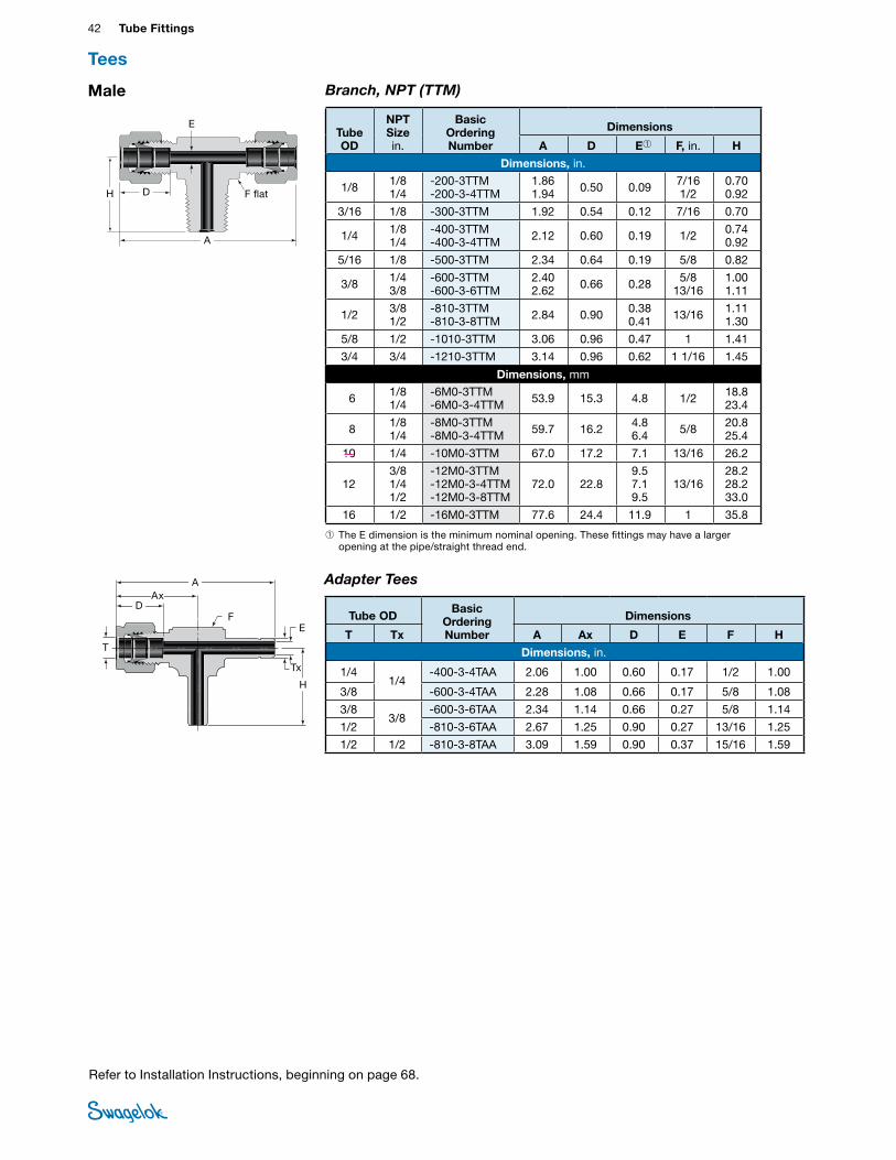
42 Tube FittingsTU
BE
FITTI
NGS
Tx
Male Branch, NPT (TTM)
D
A
H
E
➀ The E dimension is the minimum nominal opening. These fittings may have a larger opening at the pipe/straight thread end.
Tube OD
NPT Size in.
Basic Ordering Number
Dimensions
A D E➀ F, in. H
Dimensions, in.
1/8 1/8 1/4
-200-3TTM -200-3-4TTM
1.86 1.94 0.50 0.09 7/16
1/2 0.70 0.92
3/16 1/8 -300-3TTM 1.92 0.54 0.12 7/16 0.70
1/4 1/8 1/4
-400-3TTM -400-3-4TTM 2.12 0.60 0.19 1/2 0.74
0.92
5/16 1/8 -500-3TTM 2.34 0.64 0.19 5/8 0.82
3/8 1/4 3/8
-600-3TTM -600-3-6TTM
2.40 2.62 0.66 0.28 5/8
13/16 1.00 1.11
1/2 3/8 1/2
-810-3TTM -810-3-8TTM 2.84 0.90 0.38
0.41 13/16 1.11 1.30
5/8 1/2 -1010-3TTM 3.06 0.96 0.47 1 1.41
3/4 3/4 -1210-3TTM 3.14 0.96 0.62 1 1/16 1.45
Dimensions, mm
6 1/8 1/4
-6M0-3TTM -6M0-3-4TTM 53.9 15.3 4.8 1/2 18.8
23.4
8 1/8 1/4
-8M0-3TTM-8M0-3-4TTM 59.7 16.2 4.8
6.4 5/8 20.8 25.4
10 1/4 -10M0-3TTM 67.0 17.2 7.1 13/16 26.2
12 3/8 1/4 1/2
-12M0-3TTM -12M0-3-4TTM -12M0-3-8TTM
72.0 22.8 9.5 7.1 9.5
13/16 28.2 28.2 33.0
16 1/2 -16M0-3TTM 77.6 24.4 11.9 1 35.8
Tees
F flat
Refer to Installation Instructions, beginning on page 68.
Adapter Tees
Tube OD Basic
Ordering Number
Dimensions
T Tx A Ax D E F H
Dimensions, in.
1/41/4
-400-3-4TAA 2.06 1.00 0.60 0.17 1/2 1.00
3/8 -600-3-4TAA 2.28 1.08 0.66 0.17 5/8 1.08
3/83/8
-600-3-6TAA 2.34 1.14 0.66 0.27 5/8 1.14
1/2 -810-3-6TAA 2.67 1.25 0.90 0.27 13/16 1.25
1/2 1/2 -810-3-8TAA 3.09 1.59 0.90 0.37 15/16 1.59
Adapter Tee
A
H
E
T
DAx
F
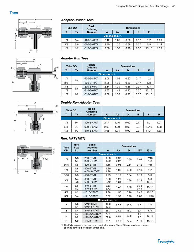
Gaugeable Tube Fittings and Adapter Fittings 43 TUBE
FITTINGS
F
Run, NPT (TMT)
➀ The E dimension is the minimum nominal opening. These fittings may have a larger opening at the pipe/straight thread end.
D
AAx
E
F flatAx
Tube OD
NPT Size in.
Basic Ordering Number
Dimensions
A Ax D E➀ F, in.
Dimensions, in.
1/8 1/8 1/4
-200-3TMT -200-3-4TMT
1.63 1.89
0.93 0.97 0.50 0.09 7/16
1/2
3/16 1/8 -300-3TMT 1.66 0.96 0.54 0.12 7/16
1/4 1/8 1/4
-400-3TMT -400-3-4TMT
1.80 1.98 1.06 0.60 0.19 1/2
5/16 1/8 -500-3TMT 1.99 1.17 0.64 0.19 5/8
3/8 1/4 3/8
-600-3TMT -600-3-6TMT
2.20 2.42
1.20 1.31 0.66 0.28 5/8
13/16
1/2 3/8 1/2
-810-3TMT -810-3-8TMT
2.53 2.72 1.42 0.90 0.38
0.41 13/16
5/8 1/2 -1010-3TMT 2.88 1.50 0.96 0.47 15/16
3/4 3/4 -1210-3TMT 3.02 1.57 0.96 0.62 1 1/16
Dimensions, mm
6 1/8 1/4
-6M0-3TMT -6M0-3-4TMT
45.8 50.3 27.0 15.3 4.8 1/2
8 1/4 -8M0-3-4TMT 55.3 29.9 16.2 6.4 5/8
12 1/4 1/2
-12M0-3-4TMT -12M0-3-8TMT
64.2 69.0 36.0 22.8 7.1
9.5 13/16
16 1/2 -16M0-3TMT 73.1 38.0 24.4 11.9 15/16
Adapter Branch Tees
Tube OD Basic
Ordering Number
Dimensions
T Tx A Ax D E F H
Dimensions, in.
1/4 1/4 -400-3-4TTA 2.12 1.06 0.60 0.17 1/2 1.00
3/8 3/8 -600-3-6TTA 2.40 1.20 0.66 0.27 5/8 1.14
1/2 1/2 -810-3-8TTA 3.00 1.50 0.90 0.37 15/16 1.59
Adapter Branch Tee
Adapter Run Tees
Tube OD Basic
Ordering Number
Dimensions
T Tx A Ax D E F
Dimensions, in.
1/41/4
-400-3-4TAT 2.06 1.06 0.60 0.17 1/2
3/8 -600-3-4TAT 2.28 1.20 0.66 0.17 5/8
3/83/8
-600-3-6TAT 2.34 1.20 0.66 0.27 5/8
1/2 -810-3-6TAT 2.67 1.42 0.90 0.27 13/16
1/2 1/2 -810-3-8TAT 3.09 1.50 0.90 0.37 15/16
Adapter Run Tee
Double Run Adapter Tees
Tube OD Basic
Ordering Number
Dimensions
T Tx A Ax D E F H
Dimensions, in.
1/4 1/4 -400-3-4AAT 2.14 1.16 0.60 0.17 1/2 1.07
3/8 3/8 -600-3-6AAT 2.66 1.39 0.66 0.27 13/16 1.33
1/2 1/2 -810-3-8AAT 3.66 1.74 0.90 0.37 1 1/4 1.83
Double Run Adapter Tee
Tees
A
A
TxE
T
D
H
Ax
AAx
D
T
Ax
E
Tx
F
FAx
Tx
E
T
D
H
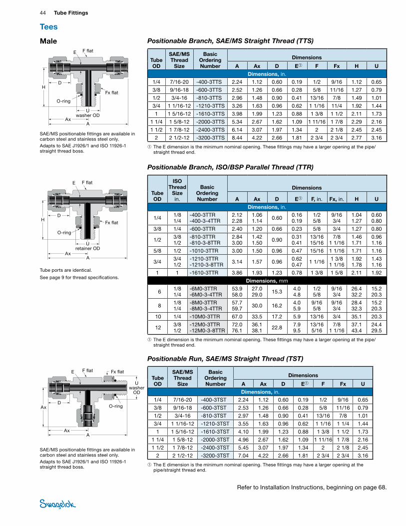
44 Tube FittingsTU
BE
FITTI
NGS
U washer
OD
D
AAx
Ax
E F flat Fx flat
O-ring
Positionable Branch, ISO/BSP Parallel Thread (TTR)
Tube ports are identical.
See page 9 for thread specifications.
➀ The E dimension is the minimum nominal opening. These fittings may have a larger opening at the pipe/straight thread end.
Tube OD
ISO Thread
Size in.
Basic Ordering Number
Dimensions
A Ax D E➀ F, in. Fx, in. H U
Dimensions, in.
1/4 1/8 1/4
-400-3TTR -400-3-4TTR
2.12 2.28
1.06 1.14 0.60 0.16
0.19 1/2 5/8
9/16 3/4
1.04 1.27
0.60 0.80
3/8 1/4 -600-3TTR 2.40 1.20 0.66 0.23 5/8 3/4 1.27 0.80
1/2 3/8 1/2
-810-3TTR -810-3-8TTR
2.84 3.00
1.42 1.50 0.90 0.31
0.41 13/16 15/16
7/8 1 1/16
1.46 1.71
0.96 1.16
5/8 1/2 -1010-3TTR 3.00 1.50 0.96 0.47 15/16 1 1/16 1.71 1.16
3/4 3/4 1/2
-1210-3TTR -1210-3-8TTR 3.14 1.57 0.96 0.62
0.47 1 1/16 1 3/8 1 1/16
1.92 1.78
1.43 1.16
1 1 -1610-3TTR 3.86 1.93 1.23 0.78 1 3/8 1 5/8 2.11 1.92
Dimensions, mm
6 1/8 1/4
-6M0-3TTR -6M0-3-4TTR
53.9 58.0
27.0 29.0 15.3 4.0
4.8 1/2 5/8
9/16 3/4
26.4 32.2
15.2 20.3
8 1/8 1/4
-8M0-3TTR -8M0-3-4TTR
57.7 59.7 30.0 16.2 4.0
5.9 9/16 5/8
9/16 3/4
28.4 32.3
15.2 20.3
10 1/4 -10M0-3TTR 67.0 33.5 17.2 5.9 13/16 3/4 35.1 20.3
12 3/8 1/2
-12M0-3TTR -12M0-3-8TTR
72.0 76.1
36.1 38.1 22.8 7.9
9.5 13/16 5/16
7/8 1 1/16
37.1 43.4
24.4 29.5
Male Positionable Branch, SAE/MS Straight Thread (TTS)
➀ The E dimension is the minimum nominal opening. These fittings may have a larger opening at the pipe/straight thread end.
Tube OD
SAE/MS Thread
Size
Basic OrderingNumber
Dimensions
A Ax D E➀ F Fx H U
Dimensions, in. 1/4 7/16-20 -400-3TTS 2.24 1.12 0.60 0.19 1/2 9/16 1.12 0.65
3/8 9/16-18 -600-3TTS 2.52 1.26 0.66 0.28 5/8 11/16 1.27 0.79
1/2 3/4-16 -810-3TTS 2.96 1.48 0.90 0.41 13/16 7/8 1.49 1.01
3/4 1 1/16-12 -1210-3TTS 3.26 1.63 0.96 0.62 1 1/16 11/4 1.92 1.44
1 1 5/16-12 -1610-3TTS 3.98 1.99 1.23 0.88 1 3/8 1 1/2 2.11 1.73
1 1/4 1 5/8-12 -2000-3TTS 5.34 2.67 1.62 1.09 1 11/16 1 7/8 2.29 2.16
1 1/2 1 7/8-12 -2400-3TTS 6.14 3.07 1.97 1.34 2 2 1/8 2.45 2.45
2 2 1/2-12 -3200-3TTS 8.44 4.22 2.66 1.81 2 3/4 2 3/4 2.77 3.16 SAE/MS positionable fittings are available in carbon steel and stainless steel only.Adapts to SAE J1926/1 and ISO 11926-1 straight thread boss.
Positionable Run, SAE/MS Straight Thread (TST)
➀ The E dimension is the minimum nominal opening. These fittings may have a larger opening at the pipe/straight thread end.
Tube OD
SAE/MS Thread
Size
Basic Ordering Number
Dimensions
A Ax D E➀ F Fx U
Dimensions, in.
1/4 7/16-20 -400-3TST 2.24 1.12 0.60 0.19 1/2 9/16 0.65
3/8 9/16-18 -600-3TST 2.53 1.26 0.66 0.28 5/8 11/16 0.79
1/2 3/4-16 -810-3TST 2.97 1.48 0.90 0.41 13/16 7/8 1.01
3/4 1 1/16-12 -1210-3TST 3.55 1.63 0.96 0.62 1 1/16 1 1/4 1.44
1 1 5/16-12 -1610-3TST 4.10 1.99 1.23 0.88 1 3/8 1 1/2 1.73
1 1/4 1 5/8-12 -2000-3TST 4.96 2.67 1.62 1.09 1 11/16 1 7/8 2.16
1 1/2 1 7/8-12 -2400-3TST 5.45 3.07 1.97 1.34 2 2 1/8 2.45
2 2 1/2-12 -3200-3TST 7.04 4.22 2.66 1.81 2 3/4 2 3/4 3.16 SAE/MS positionable fittings are available in carbon steel and stainless steel only.Adapts to SAE J1926/1 and ISO 11926-1 straight thread boss.
Tees
D
AAx
H
E F flat
Fx flat
O-ring
U washer OD
D
AAx
H
E F flat
Fx flat
O-ring
U retainer OD
Refer to Installation Instructions, beginning on page 68.
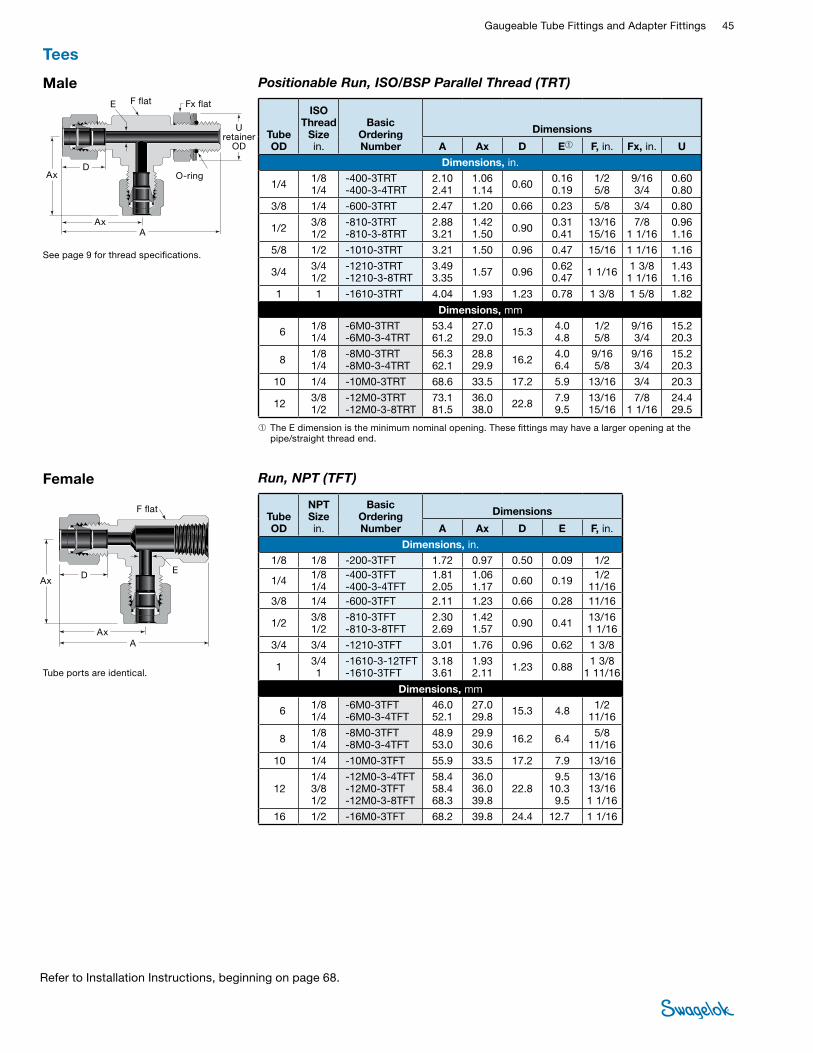
Gaugeable Tube Fittings and Adapter Fittings 45 TUBE
FITTINGS
Refer to Installation Instructions, beginning on page 68.
Positionable Run, ISO/BSP Parallel Thread (TRT)
See page 9 for thread specifications.
Male
➀ The E dimension is the minimum nominal opening. These fittings may have a larger opening at the pipe/straight thread end.
Tube OD
ISO Thread
Size in.
Basic Ordering Number
Dimensions
A Ax D E➀ F, in. Fx, in. U
Dimensions, in.
1/4 1/8 1/4
-400-3TRT -400-3-4TRT
2.10 2.41
1.06 1.14 0.60 0.16
0.19 1/2 5/8
9/16 3/4
0.60 0.80
3/8 1/4 -600-3TRT 2.47 1.20 0.66 0.23 5/8 3/4 0.80
1/2 3/8 1/2
-810-3TRT -810-3-8TRT
2.88 3.21
1.42 1.50 0.90 0.31
0.41 13/16 15/16
7/8 1 1/16
0.96 1.16
5/8 1/2 -1010-3TRT 3.21 1.50 0.96 0.47 15/16 1 1/16 1.16
3/4 3/4 1/2
-1210-3TRT -1210-3-8TRT
3.49 3.35 1.57 0.96 0.62
0.47 1 1/16 1 3/8 1 1/16
1.43 1.16
1 1 -1610-3TRT 4.04 1.93 1.23 0.78 1 3/8 1 5/8 1.82
Dimensions, mm
6 1/8 1/4
-6M0-3TRT -6M0-3-4TRT
53.4 61.2
27.0 29.0 15.3 4.0
4.8 1/2 5/8
9/16 3/4
15.2 20.3
8 1/8 1/4
-8M0-3TRT -8M0-3-4TRT
56.3 62.1
28.8 29.9 16.2 4.0
6.4 9/16 5/8
9/16 3/4
15.2 20.3
10 1/4 -10M0-3TRT 68.6 33.5 17.2 5.9 13/16 3/4 20.3
12 3/8 1/2
-12M0-3TRT -12M0-3-8TRT
73.1 81.5
36.0 38.0 22.8 7.9
9.5 13/16 15/16
7/8 1 1/16
24.4 29.5
Tube ports are identical.
Female Run, NPT (TFT)
D
AAx
AxE
F flatTube OD
NPT Sizein.
Basic OrderingNumber
Dimensions
A Ax D E F, in.
Dimensions, in. 1/8 1/8 -200-3TFT 1.72 0.97 0.50 0.09 1/2
1/4 1/8 1/4
-400-3TFT -400-3-4TFT
1.81 2.05
1.06 1.17 0.60 0.19 1/2
11/16 3/8 1/4 -600-3TFT 2.11 1.23 0.66 0.28 11/16
1/2 3/8 1/2
-810-3TFT -810-3-8TFT
2.30 2.69
1.42 1.57 0.90 0.41 13/16
1 1/16
3/4 3/4 -1210-3TFT 3.01 1.76 0.96 0.62 1 3/8
1 3/4 1
-1610-3-12TFT -1610-3TFT
3.18 3.61
1.93 2.11 1.23 0.88 1 3/8
1 11/16
Dimensions, mm
6 1/8 1/4
-6M0-3TFT -6M0-3-4TFT
46.0 52.1
27.0 29.8 15.3 4.8 1/2
11/16
8 1/8 1/4
-8M0-3TFT -8M0-3-4TFT
48.9 53.0
29.9 30.6 16.2 6.4 5/8
11/16
10 1/4 -10M0-3TFT 55.9 33.5 17.2 7.9 13/16
12 1/4 3/8 1/2
-12M0-3-4TFT -12M0-3TFT -12M0-3-8TFT
58.4 58.4 68.3
36.0 36.0 39.8
22.8 9.5
10.3 9.5
13/16 13/16 1 1/16
16 1/2 -16M0-3TFT 68.2 39.8 24.4 12.7 1 1/16
U retainer
OD
D
AAx
Ax
E F flat Fx flat
O-ring
Tees
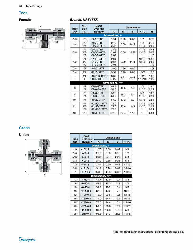
46 Tube FittingsTU
BE
FITTI
NGS
Union
Branch, NPT (TTF)
D
A
H
E
F flat
Tube OD
NPT Size in.
Basic Ordering Number
Dimensions
A D E F, in. H
Dimensions, in.
1/8 1/8 -200-3TTF 1.94 0.50 0.09 1/2 0.75
1/4 1/8 1/4
-400-3TTF -400-3-4TTF
2.12 2.34 0.60 0.19 1/2
11/16 0.75 0.88
3/8 1/4 3/8 1/2
-600-3TTF -600-3-6TTF -600-3-8TTF
2.46 2.62 2.84
0.66 0.28 11/16 13/16
1
0.88 0.88 1.12
1/2 1/4 3/8 1/2
-810-3-4TTF -810-3TTF -810-3-8TTF
2.84 2.84 3.06
0.90 0.41 13/16 13/16
1
0.88 0.88 1.12
5/8 1/2 -1010-3TTF 3.06 0.96 0.50 1 1.12
3/4 3/4 -1210-3TTF 3.52 0.96 0.62 1 3/8 1.25
1 3/4 1
-1610-3-12TTF -1610-3TTF
3.86 4.22 1.23 0.88 1 3/8
1 11/16 1.25 1.50
Dimensions, mm
6 1/8 1/4
-6M0-3TTF -6M0-3-4TTF
53.9 59.5 15.3 4.8 1/2
11/16 19.0 22.4
8 1/8 1/4
-8M0-3TTF -8M0-3-4TTF
59.7 61.2 16.2 6.4 5/8
11/16 19.0 22.4
10 1/4 -10M0-3TTF 67.0 17.2 7.9 13/16 22.4
12 1/4 3/8 1/2
-12M0-3-4TTF -12M0-3TTF -12M0-3-8TTF
72.0 72.0 77.7
22.8 9.5 13/16 13/16
1
22.4 22.4 28.4
16 1/2 -16M0-3TTF 77.6 24.4 12.7 1 28.4
Cross
D
A
A
E
F flat
Tube OD
Basic Ordering Number
Dimensions
A D E F, in.
Dimensions, in.
1/8 -200-4 1.76 0.50 0.09 3/8
1/4 -400-4 2.12 0.60 0.19 1/2
5/16 -500-4 2.34 0.64 0.25 5/8
3/8 -600-4 2.40 0.66 0.28 5/8
1/2 -810-4 2.84 0.90 0.41 13/16
3/4 -1210-4 3.14 0.96 0.62 1 1/16
1 -1610-4 3.86 1.23 0.88 1 3/8
Dimensions, mm
3 -3M0-4 44.7 12.9 2.4 3/8
6 -6M0-4 53.9 15.3 4.8 1/2
8 -8M0-4 59.7 16.2 6.4 5/8
10 -10M0-4 67.0 17.2 7.9 13/16
12 -12M0-4 72.0 22.8 9.5 13/16
16 -16M0-4 74.0 24.4 12.7 15/16
18 -18M0-4 76.6 24.4 15.1 1 1/16
20 -20M0-4 89.3 26.0 15.9 1 3/8
22 -22M0-4 89.4 26.0 18.3 5/8
25 -25M0-4 98.3 31.3 21.8 1 3/8
Female
Tees
Refer to Installation Instructions, beginning on page 68.
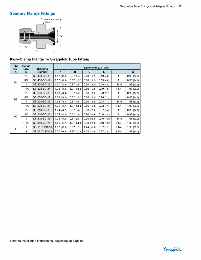
Gaugeable Tube Fittings and Adapter Fittings 47 TUBE
FITTINGS
Refer to Installation Instructions, beginning on page 68.
Sanitary Flange Fittings
A
G
F flat
B
C
E minimum opening
Tube OD in.
Flange Size in.
Ordering Number
Dimensions, in. (mm)
A B C E F G
1/4
1/2 SS-400-SC-8 1.57 (39.9) 0.37 (9.4) 0.60 (15.2) 0.19 (4.8) 1 0.98 (24.9)
3/4 SS-400-SC-12 1.57 (39.9) 0.62 (15.7) 0.60 (15.2) 0.19 (4.8) 1 0.98 (24.9)
1 SS-400-SC-16 1.57 (39.9) 0.87 (22.1) 0.60 (15.2) 0.19 (4.8) 13/16 1.98 (50.3)
1 1/2 SS-400-SC-24 1.75 (44.4) 1.37 (34.8) 0.60 (15.2) 0.19 (4.8) 1 1/4 1.98 (50.3)
3/8
1/2 SS-600-SC-8 1.63 (41.4) 0.37 (9.4) 0.66 (16.8) 0.28 (7.1) 1 0.98 (24.9)
3/4 SS-600-SC-12 1.63 (41.4) 0.62 (15.7) 0.66 (16.8) 0.28 (7.1) 1 0.98 (24.9)
1 SS-600-SC-16 1.63 (41.4) 0.87 (22.1) 0.66 (16.8) 0.28 (7.1) 13/16 1.98 (50.3)
1 1/2 SS-600-SC-24 1.72 (43.7) 1.37 (34.8) 0.66 (16.8) 0.28 (7.1) 1 1/4 1.98 (50.3)
1/2
1/2 SS-810-SC-8 1.74 (44.2) 0.37 (9.4) 0.90 (22.9) 0.37 (9.4) 1 0.98 (24.9)
3/4 SS-810-SC-12 1.74 (44.2) 0.62 (15.7) 0.90 (22.9) 0.40 (10.2) 1 0.98 (24.9)
1 SS-810-SC-16 1.74 (44.2) 0.87 (22.1) 0.90 (22.9) 0.40 (10.2) 13/16 1.98 (50.3)
1 1/2 SS-810-SC-24 1.80 (45.7) 1.37 (34.8) 0.90 (22.9) 0.40 (10.2) 1 1/4 1.98 (50.3)
1 1 SS-1610-SC-16 1.92 (48.8) 0.87 (22.1) 1.24 (31.5) 0.87 (22.1) 1 1/4 1.98 (50.3)
2 SS-1610-SC-32 2.50 (63.5) 1.87 (47.5) 1.24 (31.5) 0.87 (22.1) 2 3/4 2.52 (64.0)
Kwik-Clamp Flange To Swagelok Tube Fitting
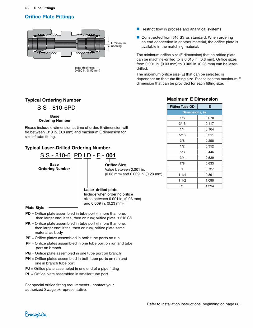
48 Tube FittingsTU
BE
FITTI
NGS
Refer to Installation Instructions, beginning on page 68.
Orifice Plate Fittings
Maximum E Dimension
Fitting Tube OD E
Dimensions, in.
1/8 0.070
3/16 0.117
1/4 0.164
5/16 0.211
3/8 0.258
1/2 0.352
5/8 0.446
3/4 0.539
7/8 0.633
1 0.727
1 1/4 0.891
1 1/2 1.090
2 1.394
E minimum opening
plate thickness: 0.060 in. (1.52 mm)
■ Restrict flow in process and analytical systems
■ Constructed from 316 SS as standard. When ordering an end connection in another material, the orifice plate is available in the matching material.
The minimum orifice size (E dimension) that an orifice plate can be machine-drilled to is 0.010 in. (0.3 mm). Orifice sizes from 0.001 in. (0.03 mm) to 0.009 in. (0.23 mm) can be laser-drilled.
The maximum orifice size (E) that can be selected is dependent on the tube fitting size. Please see the maximum E dimension that can be provided for each fitting size.
Typical Laser-Drilled Ordering Number
Plate Style
PD = Orifice plate assembled in tube port (if more than one, then larger end; if tee, then on run); orifice plate is 316 SS
PK = Orifice plate assembled in tube port (if more than one, then larger end; if tee, then on run); orifice plate same material as body
PE = Orifice plates assembled in both tube ports on run PF = Orifice plates assembled in one tube port on run and tube
port on branchPG = Orifice plate assembled in one tube port on branchPH = Orifice plates assembled in both tube ports on run and
one in branch tube port PJ = Orifice plate assembled in one end of a pipe fitting PL = Orifice plate assembled in smaller tube port
S S - 810-6 PD LD - E - 001 Base
Ordering NumberOrifice Size Value between 0.001 in. (0.03 mm) and 0.009 in. (0.23 mm).
Laser-drilled plate Include when ordering orifice sizes between 0.001 in. (0.03 mm) and 0.009 in. (0.23 mm).
For special orifice fitting requirements - contact your authorized Swagelok representative.
Please include e-dimension at time of order. E-dimension will be between .010 in. (0.3 mm) and maximum E dimension for size of tube fitting.
Typical Ordering Number
S S - 810-6PDBase
Ordering Number
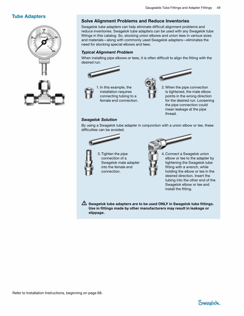
Gaugeable Tube Fittings and Adapter Fittings 49 TUBE
FITTINGS
Refer to Installation Instructions, beginning on page 68.
Solve Alignment Problems and Reduce InventoriesSwagelok tube adapters can help eliminate difficult alignment problems and reduce inventories. Swagelok tube adapters can be used with any Swagelok tube fittings in this catalog. So, stocking union elbows and union tees in various sizes and materials—along with commonly used Swagelok adapters—eliminates the need for stocking special elbows and tees.
Typical Alignment ProblemWhen installing pipe elbows or tees, it is often difficult to align the fitting with the desired run.
•Swagelok tube adapters are to be used ONLY in Swagelok tube fittings. Use in fittings made by other manufacturers may result in leakage or slippage.
Tube Adapters
- BW
1. In this example, the installation requires connecting tubing to a female end connection.
2. When the pipe connection is tightened, the male elbow points in the wrong direction for the desired run. Loosening the pipe connection could mean leakage at the pipe thread.
3. Tighten the pipe connection of a Swagelok male adapter into the female end connection.
4. Connect a Swagelok union elbow or tee to the adapter by tightening the Swagelok tube fitting with a wrench, while holding the elbow or tee in the desired direction. Insert the tubing into the other end of the Swagelok elbow or tee and install the fitting.
Swagelok SolutionBy using a Swagelok tube adapter in conjunction with a union elbow or tee, these difficulties can be avoided.
100
2000
1505
0
10
14
50
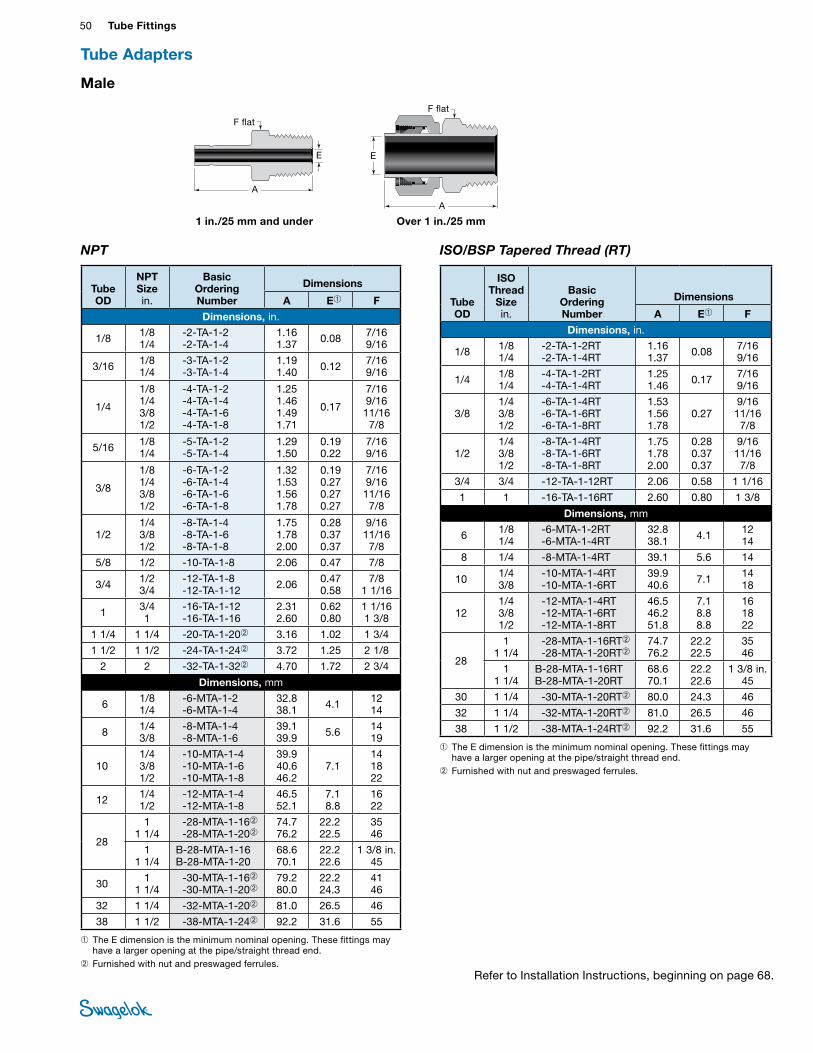
50 Tube FittingsTU
BE
FITTI
NGS
➀ The E dimension is the minimum nominal opening. These fittings may have a larger opening at the pipe/straight thread end.
➁ Furnished with nut and preswaged ferrules.
➀ The E dimension is the minimum nominal opening. These fittings may have a larger opening at the pipe/straight thread end.
➁ Furnished with nut and preswaged ferrules.
Male
NPT
1 in./25 mm and under
A
E
F flat
Over 1 in./25 mm
A
E
F flat
ISO/BSP Tapered Thread (RT)
Tube OD
NPT Size in.
Basic OrderingNumber
Dimensions
A E➀ F
Dimensions, in.
1/8 1/8 1/4
-2-TA-1-2 -2-TA-1-4
1.16 1.37 0.08 7/16
9/16
3/16 1/8 1/4
-3-TA-1-2 -3-TA-1-4
1.19 1.40 0.12 7/16
9/16
1/4
1/8 1/4 3/8 1/2
-4-TA-1-2 -4-TA-1-4 -4-TA-1-6 -4-TA-1-8
1.25 1.46 1.49 1.71
0.17
7/16 9/16 11/16 7/8
5/16 1/8 1/4
-5-TA-1-2 -5-TA-1-4
1.29 1.50
0.19 0.22
7/16 9/16
3/8
1/8 1/4 3/8 1/2
-6-TA-1-2 -6-TA-1-4 -6-TA-1-6 -6-TA-1-8
1.32 1.53 1.56 1.78
0.19 0.27 0.27 0.27
7/16 9/16 11/16 7/8
1/2 1/4 3/8 1/2
-8-TA-1-4 -8-TA-1-6 -8-TA-1-8
1.75 1.78 2.00
0.28 0.37 0.37
9/16 11/16 7/8
5/8 1/2 -10-TA-1-8 2.06 0.47 7/8
3/4 1/2 3/4
-12-TA-1-8 -12-TA-1-12 2.06 0.47
0.58 7/8
1 1/16
1 3/4 1
-16-TA-1-12 -16-TA-1-16
2.31 2.60
0.62 0.80
1 1/16 1 3/8
1 1/4 1 1/4 -20-TA-1-20➁ 3.16 1.02 1 3/4
1 1/2 1 1/2 -24-TA-1-24➁ 3.72 1.25 2 1/8
2 2 -32-TA-1-32➁ 4.70 1.72 2 3/4
Dimensions, mm
6 1/8 1/4
-6-MTA-1-2 -6-MTA-1-4
32.8 38.1 4.1 12
14
8 1/4 3/8
-8-MTA-1-4 -8-MTA-1-6
39.1 39.9 5.6 14
19
10 1/4 3/8 1/2
-10-MTA-1-4 -10-MTA-1-6 -10-MTA-1-8
39.9 40.6 46.2
7.1 14 18 22
12 1/4 1/2
-12-MTA-1-4 -12-MTA-1-8
46.5 52.1
7.1 8.8
16 22
28
1 1 1/4
-28-MTA-1-16➁ -28-MTA-1-20➁
74.7 76.2
22.2 22.5
35 46
1 1 1/4
B-28-MTA-1-16 B-28-MTA-1-20
68.6 70.1
22.2 22.6
1 3/8 in. 45
30 1 1 1/4
-30-MTA-1-16➁ -30-MTA-1-20➁
79.2 80.0
22.2 24.3
41 46
32 1 1/4 -32-MTA-1-20➁ 81.0 26.5 46
38 1 1/2 -38-MTA-1-24➁ 92.2 31.6 55
Tube OD
ISO Thread
Size in.
Basic OrderingNumber
Dimensions
A E➀ F
Dimensions, in.
1/8 1/8 1/4
-2-TA-1-2RT -2-TA-1-4RT
1.16 1.37 0.08 7/16
9/16
1/4 1/8 1/4
-4-TA-1-2RT -4-TA-1-4RT
1.25 1.46 0.17 7/16
9/16
3/8 1/4 3/8 1/2
-6-TA-1-4RT -6-TA-1-6RT -6-TA-1-8RT
1.53 1.56 1.78
0.27 9/16 11/16 7/8
1/2 1/4 3/8 1/2
-8-TA-1-4RT -8-TA-1-6RT -8-TA-1-8RT
1.75 1.78 2.00
0.28 0.37 0.37
9/16 11/16 7/8
3/4 3/4 -12-TA-1-12RT 2.06 0.58 1 1/16
1 1 -16-TA-1-16RT 2.60 0.80 1 3/8
Dimensions, mm
6 1/8 1/4
-6-MTA-1-2RT -6-MTA-1-4RT
32.8 38.1 4.1 12
14
8 1/4 -8-MTA-1-4RT 39.1 5.6 14
10 1/4 3/8
-10-MTA-1-4RT -10-MTA-1-6RT
39.9 40.6 7.1 14
18
12 1/4 3/8 1/2
-12-MTA-1-4RT -12-MTA-1-6RT -12-MTA-1-8RT
46.5 46.2 51.8
7.1 8.8 8.8
16 18 22
28
1 1 1/4
-28-MTA-1-16RT➁ -28-MTA-1-20RT➁
74.7 76.2
22.2 22.5
35 46
1 1 1/4
B-28-MTA-1-16RT B-28-MTA-1-20RT
68.6 70.1
22.2 22.6
1 3/8 in. 45
30 1 1/4 -30-MTA-1-20RT➁ 80.0 24.3 46
32 1 1/4 -32-MTA-1-20RT➁ 81.0 26.5 46
38 1 1/2 -38-MTA-1-24RT➁ 92.2 31.6 55
Tube Adapters
Refer to Installation Instructions, beginning on page 68.
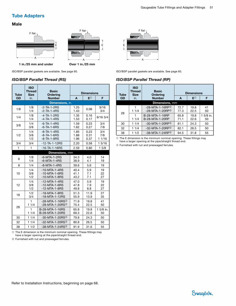
Gaugeable Tube Fittings and Adapter Fittings 51 TUBE
FITTINGS
Refer to Installation Instructions, beginning on page 68.
Male
ISO/BSP Parallel Thread (RS)
1 in./25 mm and under
A
E
Over 1 in./25 mm
A
E
F flatF flat
ISO/BSP parallel gaskets are available. See page 60.
➀ The E dimension is the minimum nominal opening. These fittings may have a larger opening at the pipe/straight thread end.
➁ Furnished with nut and preswaged ferrules.
Tube OD
ISO Thread
Size in.
Basic OrderingNumber
Dimensions
A E➀ F
Dimensions, in.
1/8 1/8 1/4
-2-TA-1-2RS -2-TA-1-4RS
1.25 1.43 0.08 9/16
3/4
1/4 1/8 1/4
-4-TA-1-2RS -4-TA-1-4RS
1.35 1.53
0.16 0.17 9/16 3/4
3/8 1/4 3/8
-6-TA-1-4RS -6-TA-1-6RS
1.59 1.62
0.23 0.27
3/4 7/8
1/2 1/4 3/8 1/2
-8-TA-1-4RS -8-TA-1-6RS -8-TA-1-8RS
1.85 1.88 1.96
0.23 0.31 0.37
3/4 7/8
1 1/16
3/4 3/4 -12-TA-1-12RS 2.20 0.58 1 5/16
1 1 -16-TA-1-16RS 2.59 0.80 1 5/8
Dimensions, mm
6 1/8 1/4
-6-MTA-1-2RS -6-MTA-1-4RS
34.3 38.9
4.0 4.1
14 19
8 1/4 -8-MTA-1-4RS 39.6 5.6 19
10 1/4 3/8 1/2
-10-MTA-1-4RS -10-MTA-1-6RS -10-MTA-1-8RS
40.4 41.1 43.2
5.9 7.1 7.1
19 22 27
12 1/4 3/8 1/2
-12-MTA-1-4RS -12-MTA-1-6RS -12-MTA-1-8RS
47.0 47.8 49.8
5.9 7.9 8.8
19 22 27
18 1/2 3/4
-18-MTA-1-8RS -18-MTA-1-12RS
51.3 55.9
11.9 13.9
27 35
28
1 1 1/4
-28-MTA-1-16RS➁ -28-MTA-1-20RS➁
71.9 75.4
19.8 22.5
41 50
1 1 1/4
B-28-MTA-1-16RS B-28-MTA-1-20RS
65.8 69.3
19.8 22.6
1 5/8 in. 50
30 1 1/4 -30-MTA-1-20RS➁ 79.8 24.3 50
32 1 1/4 -32-MTA-1-20RS➁ 80.8 26.5 50
38 1 1/2 -38-MTA-1-24RS➁ 91.9 31.6 55
ISO/BSP Parallel Thread (RP)
➀ The E dimension is the minimum nominal opening. These fittings may have a larger opening at the pipe/straight thread end.
➁ Furnished with nut and preswaged ferrules.
Tube OD
ISO Thread
Size in.
Basic OrderingNumber
Dimensions
A E➀ F
Dimensions, mm
28
1 1 1/4
-28-MTA-1-16RP➁ -28-MTA-1-20RP➁
72.7 77.3
19.8 22.5
41 50
1 1 1/4
B-28-MTA-1-16RP B-28-MTA-1-20RP
65.8 71.1
19.8 22.6
1 5/8 in. 50
30 1 1/4 -30-MTA-1-20RP➁ 81.1 24.3 50
32 1 1/4 -32-MTA-1-20RP➁ 82.1 26.5 50
38 1 1/2 -38-MTA-1-24RP➁ 94.5 31.8 55
SWAGELOK MALE TUBE ADAPTER ISO PARALLEL THREADS (RP) CUTAWAY-MS-01-140 C-PH-1061A-DIM
A
F flat
E
ISO/BSP parallel gaskets are available. See page 60.
Tube Adapters
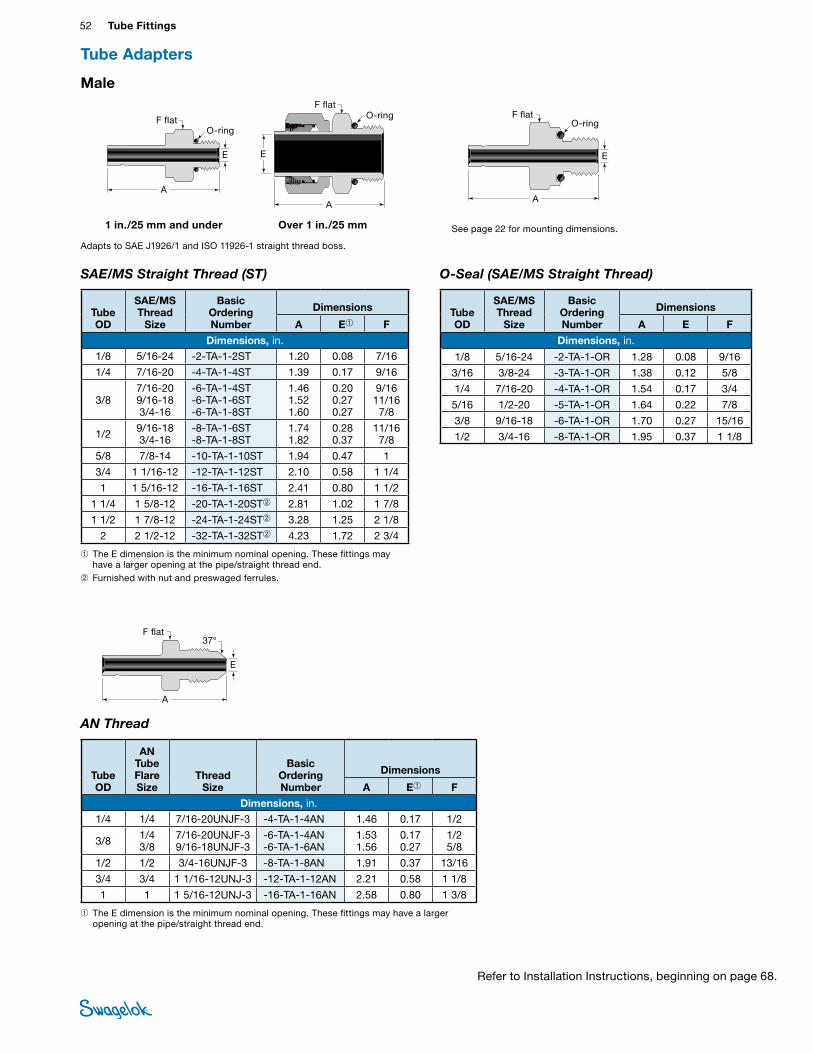
52 Tube FittingsTU
BE
FITTI
NGS
Male
O-Seal (SAE/MS Straight Thread)
See page 22 for mounting dimensions.
A
E
F flatO-ring
AN Thread
➀ The E dimension is the minimum nominal opening. These fittings may have a larger opening at the pipe/straight thread end.
A
E
F flat37°
Tube OD
SAE/MS Thread
Size
Basic OrderingNumber
Dimensions
A E F
Dimensions, in.
1/8 5/16-24 -2-TA-1-OR 1.28 0.08 9/16
3/16 3/8-24 -3-TA-1-OR 1.38 0.12 5/8
1/4 7/16-20 -4-TA-1-OR 1.54 0.17 3/4
5/16 1/2-20 -5-TA-1-OR 1.64 0.22 7/8
3/8 9/16-18 -6-TA-1-OR 1.70 0.27 15/16
1/2 3/4-16 -8-TA-1-OR 1.95 0.37 1 1/8
Tube OD
AN Tube Flare Size
Thread Size
Basic OrderingNumber
Dimensions
A E➀ F
Dimensions, in. 1/4 1/4 7/16-20UNJF-3 -4-TA-1-4AN 1.46 0.17 1/2
3/8 1/4 3/8
7/16-20UNJF-3 9/16-18UNJF-3
-6-TA-1-4AN -6-TA-1-6AN
1.53 1.56
0.17 0.27
1/2 5/8
1/2 1/2 3/4-16UNJF-3 -8-TA-1-8AN 1.91 0.37 13/16
3/4 3/4 1 1/16-12UNJ-3 -12-TA-1-12AN 2.21 0.58 1 1/8
1 1 1 5/16-12UNJ-3 -16-TA-1-16AN 2.58 0.80 1 3/8
SAE/MS Straight Thread (ST)
1 in./25 mm and under
A
E
Over 1 in./25 mm
A
E
F flatO-ring
O-ringF flat
Adapts to SAE J1926/1 and ISO 11926-1 straight thread boss.
➀ The E dimension is the minimum nominal opening. These fittings may have a larger opening at the pipe/straight thread end.
➁ Furnished with nut and preswaged ferrules.
Tube OD
SAE/MS Thread
Size
Basic OrderingNumber
Dimensions
A E➀ F
Dimensions, in. 1/8 5/16-24 -2-TA-1-2ST 1.20 0.08 7/16
1/4 7/16-20 -4-TA-1-4ST 1.39 0.17 9/16
3/8 7/16-20 9/16-18 3/4-16
-6-TA-1-4ST -6-TA-1-6ST -6-TA-1-8ST
1.46 1.52 1.60
0.20 0.27 0.27
9/16 11/16 7/8
1/2 9/16-18 3/4-16
-8-TA-1-6ST -8-TA-1-8ST
1.74 1.82
0.28 0.37
11/16 7/8
5/8 7/8-14 -10-TA-1-10ST 1.94 0.47 1
3/4 1 1/16-12 -12-TA-1-12ST 2.10 0.58 1 1/4
1 1 5/16-12 -16-TA-1-16ST 2.41 0.80 1 1/2
1 1/4 1 5/8-12 -20-TA-1-20ST➁ 2.81 1.02 1 7/8
1 1/2 1 7/8-12 -24-TA-1-24ST➁ 3.28 1.25 2 1/8
2 2 1/2-12 -32-TA-1-32ST➁ 4.23 1.72 2 3/4
Tube Adapters
Refer to Installation Instructions, beginning on page 68.

Gaugeable Tube Fittings and Adapter Fittings 53 TUBE
FITTINGS
Female
NPT ISO/BSP Tapered Thread (RT)
➀ Furnished with nut and preswaged ferrules.
1 in./25 mm and under
A
E
Over 1 in./25 mm
A
E
F flatF flat
Pipe Weld
A
JE
37.5°
Tube OD
Pipe Weld Size
Basic OrderingNumber
Dimensions
A E J
Dimensions, in. 1/4 1/4 -4-TA-1-4W 1.14 0.17 0.540
3/8 1/2 -6-TA-1-8W 1.46 0.27 0.840
1/2 1/2 3/4
-8-TA-1-8W -8-TA-1-12W
1.66 1.68 0.37 0.840
1.050
3/4 3/4 -12-TA-1-12W 1.87 0.58 1.050
Tube OD
NPT Size in.
Basic Ordering Number
Dimensions
A E F
Dimensions, in.
1/8 1/8 1/4
-2-TA-7-2 -2-TA-7-4
1.24 1.39 0.08 9/16
3/4
3/16 1/4 -3-TA-7-4 1.41 0.12 3/4
1/4
1/8 1/4 3/8 1/2
-4-TA-7-2 -4-TA-7-4 -4-TA-7-6 -4-TA-7-8
1.30 1.46 1.55 1.79
0.17
9/16 3/4 7/8
1 1/16
5/16 1/4 -5-TA-7-4 1.48 0.22 3/4
3/8
1/8 1/4 3/8 1/2
-6-TA-7-2 -6-TA-7-4 -6-TA-7-6 -6-TA-7-8
1.35 1.50 1.59 1.84
0.27
9/16 3/4 7/8
1 1/16
1/2 1/4 3/8 1/2
-8-TA-7-4 -8-TA-7-6 -8-TA-7-8
1.71 1.79 2.05
0.37 3/4 7/8
1 1/16
5/8 1/2 -10-TA-7-8 2.09 0.47 1 1/16
3/4 1/2 3/4 1
-12-TA-7-8 -12-TA-7-12 -12-TA-7-16
2.08 2.16 2.30
0.58 1 1/16 1 5/16 1 5/8
1 3/4 1
-16-TA-7-12 -16-TA-7-16
2.39 2.53 0.80 1 5/16
1 5/8
1 1/4 1 1/4 -20-TA-7-20➀ 3.06 1.02 2 1/8
1 1/2 1 1/2 -24-TA-7-24➀ 3.50 1.25 2 3/8
2 2 -32-TA-7-32➀ 4.23 1.72 2 7/8
Dimensions, mm
6 1/8 1/4
-6-MTA-7-2 -6-MTA-7-4
32.5 37.1 4.1 14
19
8 1/4 -8-MTA-7-4 37.6 5.6 19
10 1/4 3/8 1/2
-10-MTA-7-4 -10-MTA-7-6 -10-MTA-7-8
38.1 40.1 46.7
7.1 19 22 27
12 1/4 1/2
-12-MTA-7-4 -12-MTA-7-8
43.7 52.3 8.8 19
27
Tube OD
ISO Thread
Size in.
Basic Ordering Number
Dimensions
A E F
Dimensions, in.
1/4 1/8 1/4
-4-TA-7-2RT -4-TA-7-4RT
1.30 1.45 0.17 9/16
3/4
3/8 1/4 3/8
-6-TA-7-4RT -6-TA-7-6RT
1.50 1.59 0.27 3/4
7/8
1/2 1/4 3/8 1/2
-8-TA-7-4RT -8-TA-7-6RT -8-TA-7-8RT
1.71 1.80 2.05
0.37 3/4 7/8
1 1/16
Dimensions, mm
6 1/8 -6-MTA-7-2RT 33.0 4.1 14
8 1/4 -8-MTA-7-4RT 37.6 5.6 19
10 1/4 -10-MTA-7-4RT 38.1 7.1 19
Wall thickness at weld end is based on schedule 80 pipe.
Male
Tube Adapters
Refer to Installation Instructions, beginning on page 68.
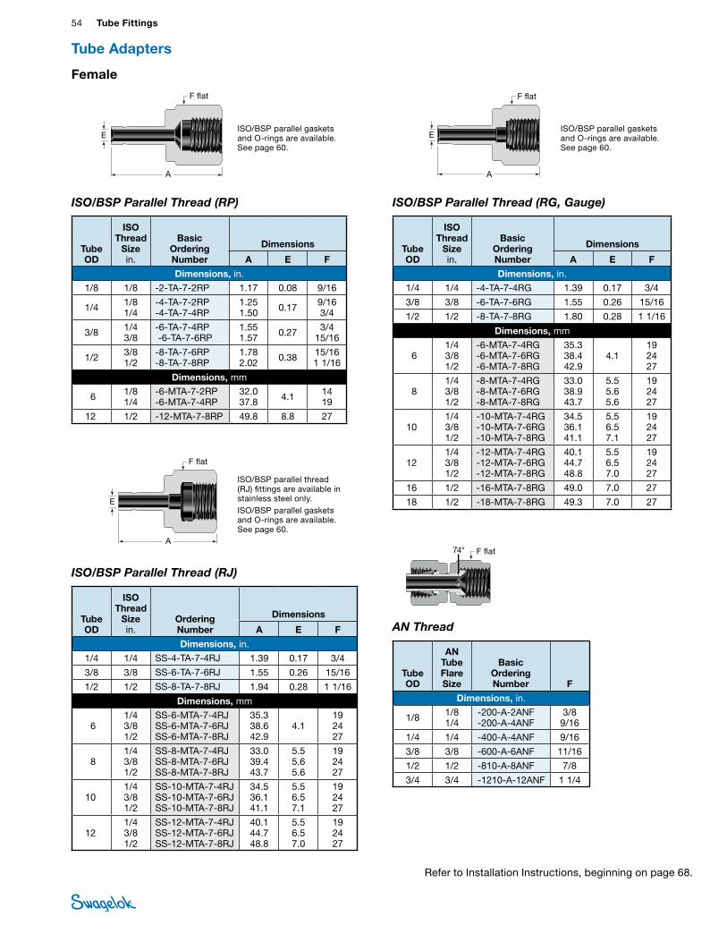
54 Tube FittingsTU
BE
FITTI
NGS
Female
ISO/BSP Parallel Thread (RP)
ISO/BSP Parallel Thread (RJ)
ISO/BSP Parallel Thread (RG, Gauge)
AN Thread
74°
ISO/BSP parallel gaskets and O-rings are available. See page 60.
A
E
F flat
A
E
F flat
A
E
F flat
F flat
Tube OD
ISO Thread
Size in.
Basic Ordering Number
Dimensions
A E F
Dimensions, in. 1/8 1/8 -2-TA-7-2RP 1.17 0.08 9/16
1/4 1/8 1/4
-4-TA-7-2RP -4-TA-7-4RP
1.25 1.50 0.17 9/16
3/4
3/8 1/4 3/8
-6-TA-7-4RP -6-TA-7-6RP
1.55 1.57 0.27 3/4
15/16
1/2 3/8 1/2
-8-TA-7-6RP -8-TA-7-8RP
1.78 2.02 0.38 15/16
1 1/16
Dimensions, mm
6 1/8 1/4
-6-MTA-7-2RP -6-MTA-7-4RP
32.0 37.8 4.1 14
19
12 1/2 -12-MTA-7-8RP 49.8 8.8 27
Tube OD
ISO Thread
Size in.
Ordering Number
Dimensions
A E F
Dimensions, in.
1/4 1/4 SS-4-TA-7-4RJ 1.39 0.17 3/4
3/8 3/8 SS-6-TA-7-6RJ 1.55 0.26 15/16
1/2 1/2 SS-8-TA-7-8RJ 1.94 0.28 1 1/16
Dimensions, mm
6 1/4 3/8 1/2
SS-6-MTA-7-4RJ SS-6-MTA-7-6RJ SS-6-MTA-7-8RJ
35.3 38.6 42.9
4.1 19 24 27
8 1/4 3/8 1/2
SS-8-MTA-7-4RJ SS-8-MTA-7-6RJ SS-8-MTA-7-8RJ
33.0 39.4 43.7
5.5 5.6 5.6
19 24 27
101/4 3/8 1/2
SS-10-MTA-7-4RJ SS-10-MTA-7-6RJ SS-10-MTA-7-8RJ
34.5 36.1 41.1
5.5 6.5 7.1
19 24 27
121/4 3/8 1/2
SS-12-MTA-7-4RJ SS-12-MTA-7-6RJ SS-12-MTA-7-8RJ
40.1 44.7 48.8
5.5 6.5 7.0
19 24 27
Tube OD
ISO Thread
Size in.
Basic Ordering Number
Dimensions
A E F
Dimensions, in. 1/4 1/4 -4-TA-7-4RG 1.39 0.17 3/4
3/8 3/8 -6-TA-7-6RG 1.55 0.26 15/16
1/2 1/2 -8-TA-7-8RG 1.80 0.28 1 1/16
Dimensions, mm
6 1/4 3/8 1/2
-6-MTA-7-4RG -6-MTA-7-6RG -6-MTA-7-8RG
35.3 38.4 42.9
4.1 19 24 27
8 1/4 3/8 1/2
-8-MTA-7-4RG -8-MTA-7-6RG -8-MTA-7-8RG
33.0 38.9 43.7
5.5 5.6 5.6
19 24 27
10 1/4 3/8 1/2
-10-MTA-7-4RG -10-MTA-7-6RG -10-MTA-7-8RG
34.5 36.1 41.1
5.5 6.5 7.1
19 24 27
12 1/4 3/8 1/2
-12-MTA-7-4RG -12-MTA-7-6RG -12-MTA-7-8RG
40.1 44.7 48.8
5.5 6.5 7.0
19 24 27
16 1/2 -16-MTA-7-8RG 49.0 7.0 27
18 1/2 -18-MTA-7-8RG 49.3 7.0 27
Tube OD
AN Tube Flare Size
Basic Ordering Number F
Dimensions, in.
1/8 1/8 1/4
-200-A-2ANF -200-A-4ANF
3/8 9/16
1/4 1/4 -400-A-4ANF 9/16
3/8 3/8 -600-A-6ANF 11/16
1/2 1/2 -810-A-8ANF 7/8
3/4 3/4 -1210-A-12ANF 1 1/4
ISO/BSP parallel gaskets and O-rings are available. See page 60.
Tube Adapters
ISO/BSP parallel thread (RJ) fittings are available in stainless steel only.ISO/BSP parallel gaskets and O-rings are available. See page 60.
Refer to Installation Instructions, beginning on page 68.
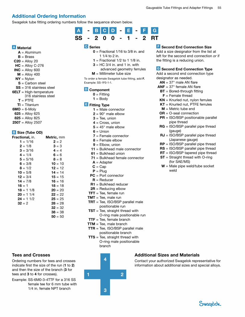
Gaugeable Tube Fittings and Adapter Fittings 55 TUBE
FITTINGS
SS - 2 0 0 - 1 - 2 RT
Additional Ordering InformationSwagelok tube fitting ordering numbers follow the sequence shown below.
SS - 2 0 0 - 1 - 2 RTA Material A = Aluminum B = Brass C20 = Alloy 20 HC = Alloy C-276 INC = Alloy 600 M = Alloy 400 NY = Nylon S = Carbon steel SS = 316 stainless steel 6ELT = High-temperature 316 stainless steel T = PTFE TI = Titanium 6MO = 6-Moly 625 = Alloy 625 825 = Alloy 825 2507 = Alloy 2507
G Second End Connection TypeAdd a second end connection type designator as needed. AN = 37° male AN flare ANF = 37° female AN flare BT = Bored-through fitting F = Female thread KN = Knurled nut, nylon ferrules KT = Knurled nut, PTFE ferrules M = Metric tube end OR = O-seal connection PR = ISO/BSP positionable parallel
pipe thread RG = ISO/BSP parallel pipe thread
(gauge) RJ = ISO/BSP parallel pipe thread
(Japanese gauge) RP = ISO/BSP parallel pipe thread RS = ISO/BSP parallel pipe thread RT = ISO/BSP tapered pipe thread ST = Straight thread with O-ring
(for SAE/MS) W = Male pipe weld/tube socket
weld
E Fitting Type 1 = Male connector 2 = 90° male elbow 3 = Tee, union 4 = Cross, union 5 = 45° male elbow 6 = Union 7 = Female connector 8 = Female elbow 9 = Elbow, union 11 = Bulkhead male connector 61 = Bulkhead union 71 = Bulkhead female connector A = Adapter C = Cap P = Plug PC = Port connector R = Reducer R1 = Bulkhead reducer 2R = Reducing elbow TFT = Tee, female run TMT = Tee, male run TRT = Tee, ISO/BSP parallel male
positionable run TST = Tee, straight thread with
O-ring male positionable run TTF = Tee, female branch TTM = Tee, male branch TTR = Tee, ISO/BSP parallel male
positionable branch TTS = Tee, straight thread with
O-ring male positionable branch
D Component 0 = Fitting 1 = Body
Fractional, in. 1 = 1/16 2 = 1/8 3 = 3/16 4 = 1/4 5 = 5/16 6 = 3/8 8 = 1/2 10 = 5/8 12 = 3/4 14 = 7/8 16 = 1 18 = 1 1/8 20 = 1 1/4 24 = 1 1/2 32 = 2
Metric, mm 2 = 2 3 = 3 4 = 4 6 = 6 8 = 8 10 = 10 12 = 12 14 = 14 15 = 15 16 = 16 18 = 18 20 = 20 22 = 22 25 = 25 28 = 28 32 = 32 38 = 38 50 = 50
Size (Tube OD)B
B DA C E G
C Series 0 = Fractional 1/16 to 3/8 in. and
1 1/4 to 2 in. 1 = Fractional 1/2 to 1 1/8 in. 3 = HC 3/4 in. and 1 in. with
advanced geometry ferrules M = Millimeter tube sizeTo order a female Swagelok tube fitting, add F.Example: SS-1F0-1-1.
F
F Second End Connection SizeAdd a size designator from the list at left for the second end connection or if the fitting is a reducing union.
Tees and CrossesOrdering numbers for tees and crosses indicate first the size of the run (1 to 2) and then the size of the branch (3 for tees and 3 to 4 for crosses).
Example: SS-6M0-3-4TTF for a 316 SS female tee for 6 mm tube with 1/4 in. female NPT branch
1 2
3
4Additional Sizes and MaterialsContact your authorized Swagelok representative for information about additional sizes and special alloys.
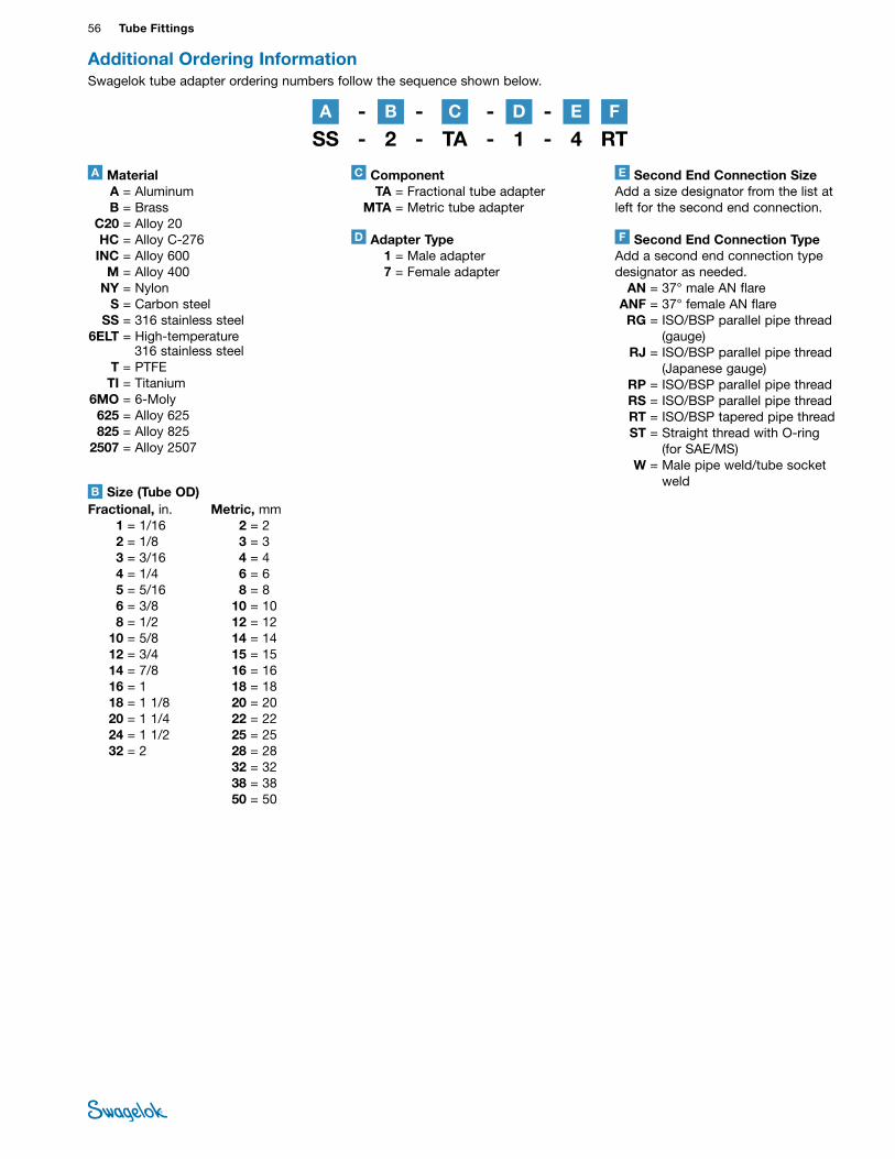
56 Tube FittingsTU
BE
FITTI
NGS
E Second End Connection SizeAdd a size designator from the list at left for the second end connection.
F Second End Connection TypeAdd a second end connection type designator as needed. AN = 37° male AN flare ANF = 37° female AN flare RG = ISO/BSP parallel pipe thread
(gauge) RJ = ISO/BSP parallel pipe thread
(Japanese gauge) RP = ISO/BSP parallel pipe thread RS = ISO/BSP parallel pipe thread RT = ISO/BSP tapered pipe thread ST = Straight thread with O-ring
(for SAE/MS) W = Male pipe weld/tube socket
weld
SS - 2 - TA - 1 - 4 RT
A Material A = Aluminum B = Brass C20 = Alloy 20 HC = Alloy C-276 INC = Alloy 600 M = Alloy 400 NY = Nylon S = Carbon steel SS = 316 stainless steel 6ELT = High-temperature 316 stainless steel T = PTFE TI = Titanium 6MO = 6-Moly 625 = Alloy 625 825 = Alloy 825 2507 = Alloy 2507
Fractional, in. 1 = 1/16 2 = 1/8 3 = 3/16 4 = 1/4 5 = 5/16 6 = 3/8 8 = 1/2 10 = 5/8 12 = 3/4 14 = 7/8 16 = 1 18 = 1 1/8 20 = 1 1/4 24 = 1 1/2 32 = 2
Metric, mm 2 = 2 3 = 3 4 = 4 6 = 6 8 = 8 10 = 10 12 = 12 14 = 14 15 = 15 16 = 16 18 = 18 20 = 20 22 = 22 25 = 25 28 = 28 32 = 32 38 = 38 50 = 50
Size (Tube OD)B
Additional Ordering InformationSwagelok tube adapter ordering numbers follow the sequence shown below.
SS - 2 - TA - 1 - 4 RT
D Adapter Type 1 = Male adapter 7 = Female adapter
C Component TA = Fractional tube adapter MTA = Metric tube adapter
B CA D FE
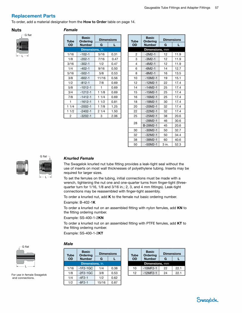
Gaugeable Tube Fittings and Adapter Fittings 57 TUBE
FITTINGS
Nuts Female
L
G flat
Knurled FemaleThe Swagelok knurled nut tube fitting provides a leak-tight seal without the use of inserts on most wall thicknesses of polyethylene tubing. Inserts may be required for larger sizes.
To set the ferrules on the tubing, initial connections must be made with a wrench, tightening the nut one and one-quarter turns from finger-tight (three-quarter turn for 1/16, 1/8 and 3/16 in.; 2, 3, and 4 mm fittings). Leak-tight connections may be reassembled with finger-tight assembly.
To order a knurled nut, add K to the female nut basic ordering number.
Example: B-402-1K
To order a knurled nut on an assembled fitting with nylon ferrules, add KN to the fitting ordering number.
Example: SS-400-1-2KN
To order a knurled nut on an assembled fitting with PTFE ferrules, add KT to the fitting ordering number.
Example: SS-400-1-2KT
L
G flat
Replacement PartsTo order, add a material designator from the How to Order table on page 14.
Tube OD
Basic Ordering Number
Dimensions
G L
Dimensions, in. 1/16 -102-1 5/16 0.31
1/8 -202-1 7/16 0.47
3/16 -302-1 1/2 0.47
1/4 -402-1 9/16 0.50
5/16 -502-1 5/8 0.53
3/8 -602-1 11/16 0.56
1/2 -812-1 7/8 0.69
5/8 -1012-1 1 0.69
3/4 -1212-1 1 1/8 0.69
7/8 -1412-1 1 1/4 0.69
1 -1612-1 1 1/2 0.81
1 1/4 -2002-1 1 7/8 1.25
1 1/2 -2402-1 2 1/4 1.50
2 -3202-1 3 2.06
Tube OD
Basic Ordering Number
Dimensions
G L
Dimensions, mm
2 -2M2-1 12 11.9
3 -3M2-1 12 11.9
4 -4M2-1 12 11.9
6 -6M2-1 14 12.7
8 -8M2-1 16 13.5
10 -10M2-1 19 15.1
12 -12M2-1 22 17.4
14 -14M2-1 25 17.4
15 -15M2-1 25 17.4
16 -16M2-1 25 17.4
18 -18M2-1 30 17.4
20 -20M2-1 32 17.4
22 -22M2-1 32 17.4
25 -25M2-1 38 20.6
28 -28M2-1 46 30.6
B-28M2-1 45 20.6
30 -30M2-1 50 32.7
32 -32M2-1 50 34.4
38 -38M2-1 60 40.6
50 -50M2-1 3 in. 52.3
For use in female Swagelok end connections.
Male
L
Tube OD
Basic Ordering Number
Dimensions
G L
Dimensions, in. 1/16 -1F2-1GC 1/4 0.38
1/8 -2F2-1GC 3/8 0.53
1/4 -4F2-1 1/2 0.62
1/2 -8F2-1 15/16 0.87
Tube OD
Basic Ordering Number
Dimensions
G L
Dimensions, mm
10 -10MF2-1 22 22.1
12 -12MF2-1 24 22.1
G flat
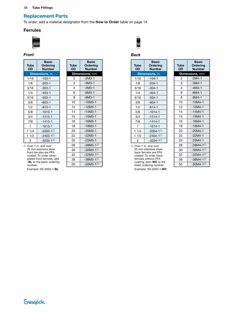
58 Tube FittingsTU
BE
FITTI
NGS
SWAGELOK BACK FERRULE CUTAWAY-MS-01-140 C-PH-0056-ADM
SWAGELOK FRONT FERRULE CUTAWAY-MS-01-140 C-PH-0056-BDM
Ferrules
Front Back
➀ Over 1 in. and over 25 mm stainless steel front ferrules are PFA coated. To order silver-plated front ferrules, add -BL to the basic ordering number.
Example: SS-2003-1-BL
➀ Over 1 in. and over 25 mm stainless steel back ferrules are PFA coated. To order back ferrules without PFA coating, add -WC to the basic ordering number.
Example: SS-2004-1-WC
Tube OD
Basic Ordering Number
Dimensions, in.
1/16 -103-1
1/8 -203-1
3/16 -303-1
1/4 -403-1
5/16 -503-1
3/8 -603-1
1/2 -813-1
5/8 -1013-1
3/4 -1213-1
7/8 -1413-1
1 -1613-1
1 1/4 -2003-1➀
1 1/2 -2403-1➀
2 -3203-1➀
Tube OD
Basic Ordering Number
Dimensions, mm2 -2M3-1
3 -3M3-1
4 -4M3-1
6 -6M3-1
8 -8M3-1
10 -10M3-1
12 -12M3-1
14 -14M3-1
15 -15M3-1
16 -16M3-1
18 -18M3-1
20 -20M3-1
22 -22M3-1
25 -25M3-1
28 -28M3-1➀
30 -30M3-1➀
32 -32M3-1➀
38 -38M3-1➀
50 -50M3-1➀
Tube OD
Basic Ordering Number
Dimensions, in.
1/16 -104-1
1/8 -204-1
3/16 -304-1
1/4 -404-1
5/16 -504-1
3/8 -604-1
1/2 -814-1
5/8 -1014-1
3/4 -1214-1
7/8 -1414-1
1 -1614-1
1 1/4 -2004-1➀
1 1/2 -2404-1➀
2 -3204-1➀
Tube OD
Basic Ordering Number
Dimensions, mm2 -2M4-1
3 -3M4-1
4 -4M4-1
6 -6M4-1
8 -8M4-1
10 -10M4-1
12 -12M4-1
14 -14M4-1
15 -15M4-1
16 -16M4-1
18 -18M4-1
20 -20M4-1
22 -22M4-1
25 -25M4-1
28 -28M4-1➀
30 -30M4-1➀
32 -32M4-1➀
38 -38M4-1➀
50 -50M4-1➀
Replacement PartsTo order, add a material designator from the How to Order table on page 14.
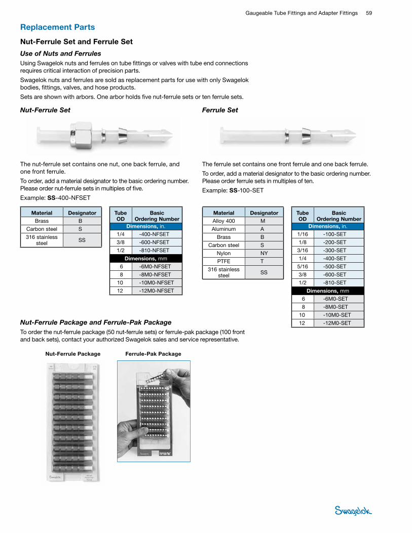
Gaugeable Tube Fittings and Adapter Fittings 59 TUBE
FITTINGS
Nut-Ferrule Set and Ferrule Set
Ferrule Set
The ferrule set contains one front ferrule and one back ferrule.
To order, add a material designator to the basic ordering number. Please order ferrule sets in multiples of ten.
Example: SS-100-SET
Nut-Ferrule Set
The nut-ferrule set contains one nut, one back ferrule, and one front ferrule.
To order, add a material designator to the basic ordering number. Please order nut-ferrule sets in multiples of five.
Example: SS-400-NFSET
Use of Nuts and FerrulesUsing Swagelok nuts and ferrules on tube fittings or valves with tube end connections requires critical interaction of precision parts.
Swagelok nuts and ferrules are sold as replacement parts for use with only Swagelok bodies, fittings, valves, and hose products.
Sets are shown with arbors. One arbor holds five nut-ferrule sets or ten ferrule sets.
Nut-Ferrule Package and Ferrule-Pak PackageTo order the nut-ferrule package (50 nut-ferrule sets) or ferrule-pak package (100 front and back sets), contact your authorized Swagelok sales and service representative.
Ferrule-Pak PackageNut-Ferrule Package
Material Designator Brass B
Carbon steel S
316 stainless steel SS
Tube OD
Basic Ordering Number
Dimensions, in. 1/4 -400-NFSET
3/8 -600-NFSET
1/2 -810-NFSET
Dimensions, mm 6 -6M0-NFSET
8 -8M0-NFSET
10 -10M0-NFSET
12 -12M0-NFSET
Material Designator Alloy 400 M
Aluminum A
Brass B
Carbon steel S
Nylon NY
PTFE T
316 stainless steel SS
Tube OD
Basic Ordering Number
Dimensions, in. 1/16 -100-SET
1/8 -200-SET
3/16 -300-SET
1/4 -400-SET
5/16 -500-SET
3/8 -600-SET
1/2 -810-SET
Dimensions, mm 6 -6M0-SET
8 -8M0-SET
10 -10M0-SET
12 -12M0-SET
Replacement Parts
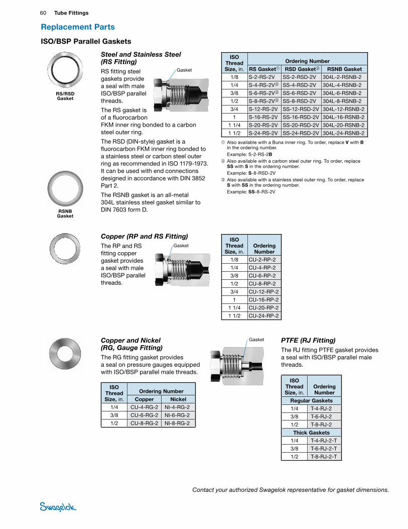
60 Tube FittingsTU
BE
FITTI
NGS
ISO/BSP Parallel Gaskets
Copper (RP and RS Fitting)The RP and RS fitting copper gasket provides a seal with male ISO/BSP parallel threads.
GasketISO
Thread Size, in.
OrderingNumber
1/8 CU-2-RP-2
1/4 CU-4-RP-2
3/8 CU-6-RP-2
1/2 CU-8-RP-2
3/4 CU-12-RP-2
1 CU-16-RP-2
1 1/4 CU-20-RP-2
1 1/2 CU-24-RP-2
Copper and Nickel (RG, Gauge Fitting)The RG fitting gasket provides a seal on pressure gauges equipped with ISO/BSP parallel male threads.
Gasket
ISO Thread Size, in.
Ordering Number
Copper Nickel1/4 CU-4-RG-2 NI-4-RG-2
3/8 CU-6-RG-2 NI-6-RG-2
1/2 CU-8-RG-2 NI-8-RG-2
ISO Thread Size, in.
OrderingNumber
Regular Gaskets1/4 T-4-RJ-2
3/8 T-6-RJ-2
1/2 T-8-RJ-2
Thick Gaskets1/4 T-4-RJ-2-T
3/8 T-6-RJ-2-T
1/2 T-8-RJ-2-T
PTFE (RJ Fitting)The RJ fitting PTFE gasket provides a seal with ISO/BSP parallel male threads.
Replacement Parts
Steel and Stainless Steel (RS Fitting)RS fitting steel gaskets provide a seal with male ISO/BSP parallel threads.
The RS gasket is of a fluorocarbon FKM inner ring bonded to a carbon steel outer ring.
The RSD (DIN-style) gasket is a fluorocarbon FKM inner ring bonded to a stainless steel or carbon steel outer ring as recommended in ISO 1179-1973. It can be used with end connections designed in accordance with DIN 3852 Part 2.
The RSNB gasket is an all-metal 304L stainless steel gasket similar to DIN 7603 form D.
Gasket
➀ Also available with a Buna inner ring. To order, replace V with B in the ordering number.
Example: S-2-RS-2B➁ Also available with a carbon steel outer ring. To order, replace
SS with S in the ordering number. Example: S-8-RSD-2V➂ Also available with a stainless steel outer ring. To order, replace
S with SS in the ordering number. Example: SS-8-RS-2V
ISO Thread Size, in.
Ordering Number
RS Gasket➀ RSD Gasket➁ RSNB Gasket1/8 S-2-RS-2V SS-2-RSD-2V 304L-2-RSNB-2
1/4 S-4-RS-2V➂ SS-4-RSD-2V 304L-4-RSNB-2
3/8 S-6-RS-2V➂ SS-6-RSD-2V 304L-6-RSNB-2
1/2 S-8-RS-2V➂ SS-8-RSD-2V 304L-8-RSNB-2
3/4 S-12-RS-2V SS-12-RSD-2V 304L-12-RSNB-2
1 S-16-RS-2V SS-16-RSD-2V 304L-16-RSNB-2
1 1/4 S-20-RS-2V SS-20-RSD-2V 304L-20-RSNB-2
1 1/2 S-24-RS-2V SS-24-RSD-2V 304L-24-RSNB-2
RS/RSD Gasket
RSNB Gasket
Contact your authorized Swagelok representative for gasket dimensions.
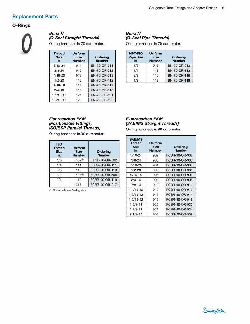
Gaugeable Tube Fittings and Adapter Fittings 61 TUBE
FITTINGS
O-Rings
Fluorocarbon FKM (Positionable Fittings, ISO/BSP Parallel Threads)O-ring hardness is 90 durometer.
Buna N (O-Seal Straight Threads)O-ring hardness is 70 durometer.
Thread Size in.
Uniform Size
Number Ordering Number
5/16-24 011 BN-70-OR-011
3/8-24 012 BN-70-OR-012
7/16-20 013 BN-70-OR-013
1/2-20 112 BN-70-OR-112
9/16-18 113 BN-70-OR-113
3/4-16 116 BN-70-OR-116
1 1/16-12 121 BN-70-OR-121
1 5/16-12 125 BN-70-OR-125
➀ Not a uniform O-ring size.
ISO Thread
Size in.
Uniform Size
Number Ordering Number
1/8 502➀ FSP-90-OR-502
1/4 111 FCBR-90-OR-111
3/8 113 FCBR-90-OR-113
1/2 508➀ FCBR-90-OR-508
3/4 119 FCBR-90-OR-119
1 217 FCBR-90-OR-217
Buna N (O-Seal Pipe Threads)O-ring hardness is 70 durometer.
Fluorocarbon FKM (SAE/MS Straight Threads)O-ring hardness is 90 durometer.
NPT/ISO Pipe Size
in.
Uniform Size
Number Ordering Number
1/8 013 BN-70-OR-013
1/4 113 BN-70-OR-113
3/8 116 BN-70-OR-116
1/2 118 BN-70-OR-118
SAE/MS Thread
Size in.
Uniform Size
Number Ordering Number
5/16-24 902 FCBR-90-OR-902
3/8-24 903 FCBR-90-OR-903
7/16-20 904 FCBR-90-OR-904
1/2-20 905 FCBR-90-OR-905
9/16-18 906 FCBR-90-OR-906
3/4-16 908 FCBR-90-OR-908
7/8-14 910 FCBR-90-OR-910
1 1/16-12 912 FCBR-90-OR-912
1 3/16-12 914 FCBR-90-OR-914
1 5/16-12 916 FCBR-90-OR-916
1 5/8-12 920 FCBR-90-OR-920
1 7/8-12 924 FCBR-90-OR-924
2 1/2-12 932 FCBR-90-OR-932
Replacement Parts
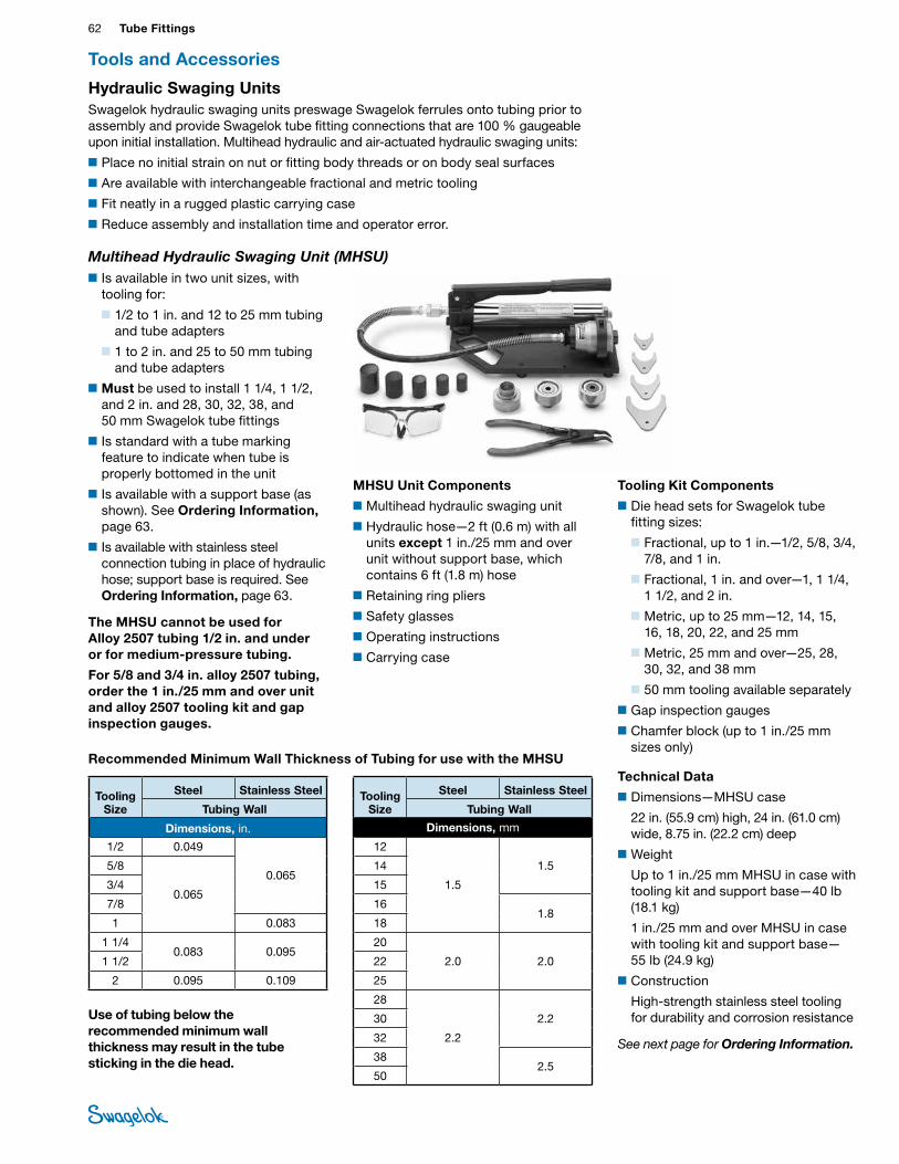
62 Tube FittingsTU
BE
FITTI
NGS
■Is available in two unit sizes, with tooling for:
■ 1/2 to 1 in. and 12 to 25 mm tubing and tube adapters
■ 1 to 2 in. and 25 to 50 mm tubing and tube adapters
■Must be used to install 1 1/4, 1 1/2, and 2 in. and 28, 30, 32, 38, and 50 mm Swagelok tube fittings
■Is standard with a tube marking feature to indicate when tube is properly bottomed in the unit
■Is available with a support base (as shown). See Ordering Information, page 63.
■ Is available with stainless steel connection tubing in place of hydraulic hose; support base is required. See Ordering Information, page 63.
The MHSU cannot be used for Alloy 2507 tubing 1/2 in. and under or for medium-pressure tubing.
For 5/8 and 3/4 in. alloy 2507 tubing, order the 1 in./25 mm and over unit and alloy 2507 tooling kit and gap inspection gauges.
Recommended Minimum Wall Thickness of Tubing for use with the MHSU
Use of tubing below the recommended minimum wall thickness may result in the tube sticking in the die head.
Tooling Size
Steel Stainless Steel
Tubing Wall
Dimensions, in.
1/2 0.049
0.065 5/8
0.065 3/4
7/8
1 0.083
1 1/4 0.083 0.095
1 1/2
2 0.095 0.109
Tooling Size
Steel Stainless Steel
Tubing Wall
Dimensions, mm
12
1.5
1.5 14
15
16 1.8
18
20
2.0 2.0 22
25
28
2.2
2.2 30
32
38 2.5
50
MHSU Unit Components
■Multihead hydraulic swaging unit
■Hydraulic hose—2 ft (0.6 m) with all units except 1 in./25 mm and over unit without support base, which contains 6 ft (1.8 m) hose
■Retaining ring pliers
■Safety glasses
■Operating instructions
■Carrying case
Hydraulic Swaging UnitsSwagelok hydraulic swaging units preswage Swagelok ferrules onto tubing prior to assembly and provide Swagelok tube fitting connections that are 100 % gaugeable upon initial installation. Multihead hydraulic and air-actuated hydraulic swaging units:
■Place no initial strain on nut or fitting body threads or on body seal surfaces
■Are available with interchangeable fractional and metric tooling
■Fit neatly in a rugged plastic carrying case
■Reduce assembly and installation time and operator error.
Tools and Accessories
Tooling Kit Components
■Die head sets for Swagelok tube fitting sizes:
■ Fractional, up to 1 in.—1/2, 5/8, 3/4, 7/8, and 1 in.
■Fractional, 1 in. and over—1, 1 1/4, 1 1/2, and 2 in.
■Metric, up to 25 mm—12, 14, 15, 16, 18, 20, 22, and 25 mm
■Metric, 25 mm and over—25, 28, 30, 32, and 38 mm
■50 mm tooling available separately
■Gap inspection gauges
■Chamfer block (up to 1 in./25 mm sizes only)
Technical Data
■Dimensions—MHSU case
22 in. (55.9 cm) high, 24 in. (61.0 cm) wide, 8.75 in. (22.2 cm) deep
■Weight
Up to 1 in./25 mm MHSU in case with tooling kit and support base—40 lb (18.1 kg)
1 in./25 mm and over MHSU in case with tooling kit and support base—55 lb (24.9 kg)
■Construction
High-strength stainless steel tooling for durability and corrosion resistance
See next page for Ordering Information.
Multihead Hydraulic Swaging Unit (MHSU)
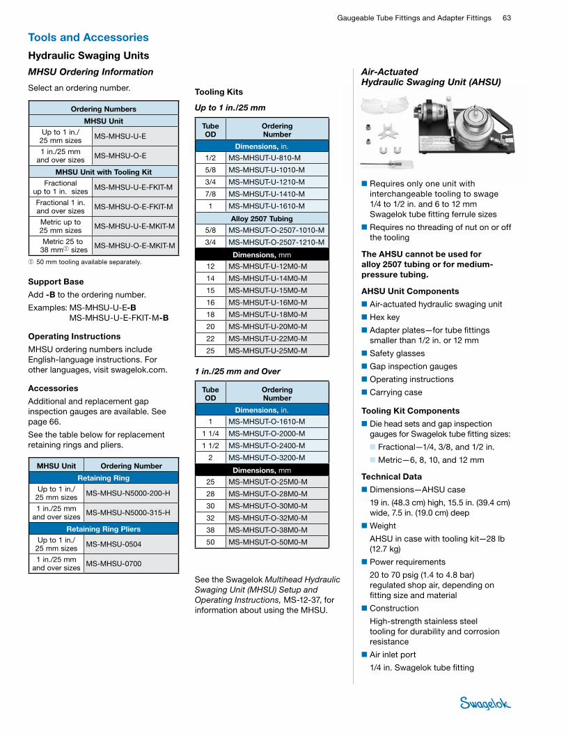
Gaugeable Tube Fittings and Adapter Fittings 63 TUBE
FITTINGS
1 in./25 mm and Over
Tube OD
Ordering Number
Dimensions, in.
1 MS-MHSUT-O-1610-M
1 1/4 MS-MHSUT-O-2000-M
1 1/2 MS-MHSUT-O-2400-M
2 MS-MHSUT-O-3200-M
Dimensions, mm
25 MS-MHSUT-O-25M0-M
28 MS-MHSUT-O-28M0-M
30 MS-MHSUT-O-30M0-M
32 MS-MHSUT-O-32M0-M
38 MS-MHSUT-O-38M0-M
50 MS-MHSUT-O-50M0-M
Tooling Kits
Up to 1 in./25 mm
Tube OD
Ordering Number
Dimensions, in.
1/2 MS-MHSUT-U-810-M
5/8 MS-MHSUT-U-1010-M
3/4 MS-MHSUT-U-1210-M
7/8 MS-MHSUT-U-1410-M
1 MS-MHSUT-U-1610-M
Alloy 2507 Tubing
5/8 MS-MHSUT-O-2507-1010-M
3/4 MS-MHSUT-O-2507-1210-M
Dimensions, mm
12 MS-MHSUT-U-12M0-M
14 MS-MHSUT-U-14M0-M
15 MS-MHSUT-U-15M0-M
16 MS-MHSUT-U-16M0-M
18 MS-MHSUT-U-18M0-M
20 MS-MHSUT-U-20M0-M
22 MS-MHSUT-U-22M0-M
25 MS-MHSUT-U-25M0-M
MHSU Ordering Information
Select an ordering number.
Ordering Numbers
MHSU Unit Up to 1 in./
25 mm sizes MS-MHSU-U-E
1 in./25 mm and over sizes MS-MHSU-O-E
MHSU Unit with Tooling Kit Fractional
up to 1 in. sizes MS-MHSU-U-E-FKIT-M
Fractional 1 in. and over sizes MS-MHSU-O-E-FKIT-M
Metric up to 25 mm sizes MS-MHSU-U-E-MKIT-M
Metric 25 to 38 mm➀ sizes MS-MHSU-O-E-MKIT-M
➀50 mm tooling available separately.
Support Base
Add -B to the ordering number.
Examples: MS-MHSU-U-E-B MS-MHSU-U-E-FKIT-M-B
Operating Instructions
MHSU ordering numbers include English-language instructions. For other languages, visit swagelok.com.
Accessories
Additional and replacement gap inspection gauges are available. See page 66.
See the table below for replacement retaining rings and pliers.
MHSU Unit Ordering Number
Retaining RingUp to 1 in./
25 mm sizes MS-MHSU-N5000-200-H
1 in./25 mm and over sizes MS-MHSU-N5000-315-H
Retaining Ring PliersUp to 1 in./
25 mm sizes MS-MHSU-0504
1 in./25 mm and over sizes MS-MHSU-0700
■Requires only one unit with interchangeable tooling to swage 1/4 to 1/2 in. and 6 to 12 mm Swagelok tube fitting ferrule sizes
■Requires no threading of nut on or off the tooling
The AHSU cannot be used for alloy 2507 tubing or for medium-pressure tubing.
AHSU Unit Components
■Air-actuated hydraulic swaging unit
■Hex key
■Adapter plates—for tube fittings smaller than 1/2 in. or 12 mm
■Safety glasses
■Gap inspection gauges
■Operating instructions
■Carrying case
Tooling Kit Components
■Die head sets and gap inspection gauges for Swagelok tube fitting sizes:
■ Fractional—1/4, 3/8, and 1/2 in.
■ Metric—6, 8, 10, and 12 mm
Technical Data
■Dimensions—AHSU case
19 in. (48.3 cm) high, 15.5 in. (39.4 cm) wide, 7.5 in. (19.0 cm) deep
■Weight
AHSU in case with tooling kit—28 lb (12.7 kg)
■Power requirements
20 to 70 psig (1.4 to 4.8 bar) regulated shop air, depending on fitting size and material
■Construction
High-strength stainless steel tooling for durability and corrosion resistance
■Air inlet port
1/4 in. Swagelok tube fitting
Tools and Accessories
Hydraulic Swaging Units
Air-Actuated Hydraulic Swaging Unit (AHSU)
See the Swagelok Multihead Hydraulic Swaging Unit (MHSU) Setup and Operating Instructions, MS-12-37, for information about using the MHSU.
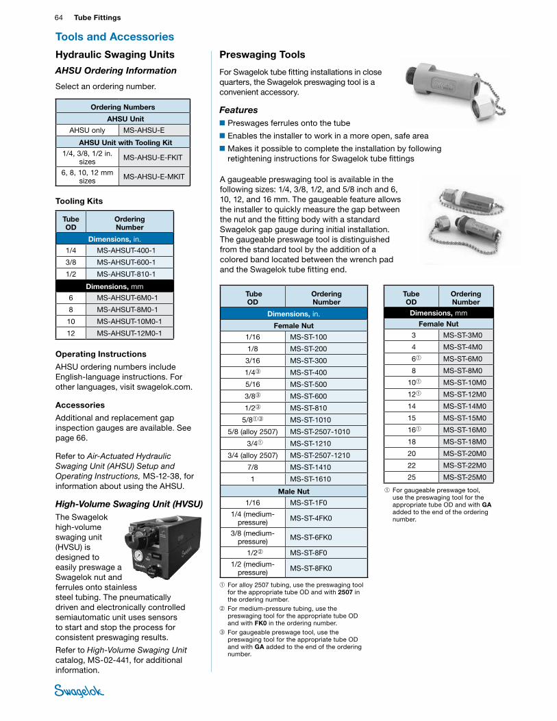
64 Tube FittingsTU
BE
FITTI
NGS
AHSU Ordering Information
Select an ordering number.
Ordering Numbers
AHSU Unit
AHSU only MS-AHSU-E
AHSU Unit with Tooling Kit 1/4, 3/8, 1/2 in.
sizes MS-AHSU-E-FKIT
6, 8, 10, 12 mm sizes MS-AHSU-E-MKIT
Tooling Kits
Tube OD
Ordering Number
Dimensions, in.
1/4 MS-AHSUT-400-1
3/8 MS-AHSUT-600-1
1/2 MS-AHSUT-810-1
Dimensions, mm
6 MS-AHSUT-6M0-1
8 MS-AHSUT-8M0-1
10 MS-AHSUT-10M0-1
12 MS-AHSUT-12M0-1
Operating Instructions
AHSU ordering numbers include English-language instructions. For other languages, visit swagelok.com.
Accessories
Additional and replacement gap inspection gauges are available. See page 66.
Refer to Air-Actuated Hydraulic Swaging Unit (AHSU) Setup and Operating Instructions, MS-12-38, for information about using the AHSU.
High-Volume Swaging Unit (HVSU)The Swagelok high-volume swaging unit (HVSU) is designed to easily preswage a Swagelok nut and ferrules onto stainless steel tubing. The pneumatically driven and electronically controlled semiautomatic unit uses sensors to start and stop the process for consistent preswaging results.
Refer to High-Volume Swaging Unit catalog, MS-02-441, for additional information.
Tools and Accessories
Hydraulic Swaging Units Preswaging Tools
For Swagelok tube fitting installations in close quarters, the Swagelok preswaging tool is a convenient accessory.
Features■Preswages ferrules onto the tube
■Enables the installer to work in a more open, safe area
■Makes it possible to complete the installation by following retightening instructions for Swagelok tube fittings
Tube OD
Ordering Number
Dimensions, mm
Female Nut
3 MS-ST-3M0
4 MS-ST-4M0
6➀ MS-ST-6M0
8 MS-ST-8M0
10➀ MS-ST-10M0
12➀ MS-ST-12M0
14 MS-ST-14M0
15 MS-ST-15M0
16➀ MS-ST-16M0
18 MS-ST-18M0
20 MS-ST-20M0
22 MS-ST-22M0
25 MS-ST-25M0
Tube OD
Ordering Number
Dimensions, in.
Female Nut
1/16 MS-ST-100
1/8 MS-ST-200
3/16 MS-ST-300
1/4➂ MS-ST-400
5/16 MS-ST-500
3/8➂ MS-ST-600
1/2➂ MS-ST-810
5/8➀➂ MS-ST-1010
5/8 (alloy 2507) MS-ST-2507-1010
3/4➀ MS-ST-1210
3/4 (alloy 2507) MS-ST-2507-1210
7/8 MS-ST-1410
1 MS-ST-1610
Male Nut
1/16 MS-ST-1F0
1/4 (medium-pressure) MS-ST-4FK0
3/8 (medium-pressure) MS-ST-6FK0
1/2➁ MS-ST-8F0
1/2 (medium-pressure) MS-ST-8FK0
➀ For alloy 2507 tubing, use the preswaging tool for the appropriate tube OD and with 2507 in the ordering number.
➁ For medium-pressure tubing, use the preswaging tool for the appropriate tube OD and with FK0 in the ordering number.
➂ For gaugeable preswage tool, use the preswaging tool for the appropriate tube OD and with GA added to the end of the ordering number.
➀ For gaugeable preswage tool, use the preswaging tool for the appropriate tube OD and with GA added to the end of the ordering number.
A gaugeable preswaging tool is available in the following sizes: 1/4, 3/8, 1/2, and 5/8 inch and 6, 10, 12, and 16 mm. The gaugeable feature allows the installer to quickly measure the gap between the nut and the fitting body with a standard Swagelok gap gauge during initial installation. The gaugeable preswage tool is distinguished from the standard tool by the addition of a colored band located between the wrench pad and the Swagelok tube fitting end.
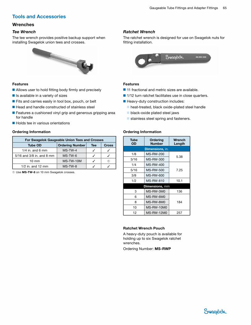
Gaugeable Tube Fittings and Adapter Fittings 65 TUBE
FITTINGS
Tee WrenchThe tee wrench provides positive backup support when installing Swagelok union tees and crosses.
Features
■Allows user to hold fitting body firmly and precisely
■Is available in a variety of sizes
■Fits and carries easily in tool box, pouch, or belt
■Head and handle constructed of stainless steel
■Features a cushioned vinyl grip and generous gripping area for handle
■Holds tee in various orientations
Ratchet WrenchThe ratchet wrench is designed for use on Swagelok nuts for fitting installation.
Features■11 fractional and metric sizes are available.
■1/12 turn ratchet facilitates use in close quarters.
■Heavy-duty construction includes:
■heat-treated, black oxide-plated steel handle
■black-oxide plated steel jaws
■stainless steel spring and fasteners.
Ordering Information
Tube OD
Ordering Number
Wrench Length
Dimensions, in.
1/8 MS-RW-200 5.38
3/16 MS-RW-300
1/4 MS-RW-400
7.25 5/16 MS-RW-500
3/8 MS-RW-600
1/2 MS-RW-810 10.1
Dimensions, mm
3 MS-RW-3M0 136
6 MS-RW-6M0
184 8 MS-RW-8M0
10 MS-RW-10M0
12 MS-RW-12M0 257
Ordering Information
For Swagelok Gaugeable Union Tees and Crosses
Tube OD Ordering Number Tee Cross
1/4 in. and 6 mm MS-TW-4 ✓ ✓
5/16 and 3/8 in. and 8 mm MS-TW-6 ✓ ✓
10 mm MS-TW-10M ✓ ➀
1/2 in. and 12 mm MS-TW-8 ✓ ✓
➀ Use MS-TW-8 on 10 mm Swagelok crosses.
Ratchet Wrench Pouch
A heavy-duty pouch is available for holding up to six Swagelok ratchet wrenches.
Ordering Number: MS-RWP
Tools and Accessories
Wrenches
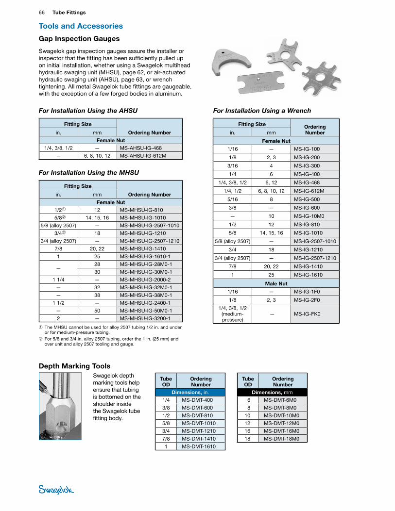
66 Tube FittingsTU
BE
FITTI
NGS
Swagelok gap inspection gauges assure the installer or inspector that the fitting has been sufficiently pulled up on initial installation, whether using a Swagelok multihead hydraulic swaging unit (MHSU), page 62, or air-actuated hydraulic swaging unit (AHSU), page 63, or wrench tightening. All metal Swagelok tube fittings are gaugeable, with the exception of a few forged bodies in aluminum.
For Installation Using the MHSU
➀ The MHSU cannot be used for alloy 2507 tubing 1/2 in. and under or for medium-pressure tubing.
➁ For 5/8 and 3/4 in. alloy 2507 tubing, order the 1 in. (25 mm) and over unit and alloy 2507 tooling and gauge.
For Installation Using the AHSU
Fitting Size
Ordering Number in. mm
Female Nut 1/4, 3/8, 1/2 — MS-AHSU-IG-468
— 6, 8, 10, 12 MS-AHSU-IG-612M
Fitting Size
Ordering Number in. mm
Female Nut 1/2➀ 12 MS-MHSU-IG-810
5/8➁ 14, 15, 16 MS-MHSU-IG-1010
5/8 (alloy 2507) — MS-MHSU-IG-2507-1010
3/4➁ 18 MS-MHSU-IG-1210
3/4 (alloy 2507) — MS-MHSU-IG-2507-1210
7/8 20, 22 MS-MHSU-IG-1410
1 25 MS-MHSU-IG-1610-1
— 28 MS-MHSU-IG-28M0-1
30 MS-MHSU-IG-30M0-1
1 1/4 — MS-MHSU-IG-2000-2
— 32 MS-MHSU-IG-32M0-1
— 38 MS-MHSU-IG-38M0-1
1 1/2 — MS-MHSU-IG-2400-1
— 50 MS-MHSU-IG-50M0-1
2 — MS-MHSU-IG-3200-1
Tools and Accessories
Depth Marking ToolsSwagelok depth marking tools help ensure that tubing is bottomed on the shoulder inside the Swagelok tube fitting body.
Tube OD
Ordering Number
Dimensions, in.
1/4 MS-DMT-400
3/8 MS-DMT-600
1/2 MS-DMT-810
5/8 MS-DMT-1010
3/4 MS-DMT-1210
7/8 MS-DMT-1410
1 MS-DMT-1610
Tube OD
Ordering Number
Dimensions, mm
6 MS-DMT-6M0
8 MS-DMT-8M0
10 MS-DMT-10M0
12 MS-DMT-12M0
16 MS-DMT-16M0
18 MS-DMT-18M0
For Installation Using a Wrench
Fitting Size Ordering Number in. mm
Female Nut
1/16 — MS-IG-100
1/8 2, 3 MS-IG-200
3/16 4 MS-IG-300
1/4 6 MS-IG-400
1/4, 3/8, 1/2 6, 12 MS-IG-468
1/4, 1/2 6, 8, 10, 12 MS-IG-612M
5/16 8 MS-IG-500
3/8 — MS-IG-600
— 10 MS-IG-10M0
1/2 12 MS-IG-810
5/8 14, 15, 16 MS-IG-1010
5/8 (alloy 2507) — MS-IG-2507-1010
3/4 18 MS-IG-1210
3/4 (alloy 2507) — MS-IG-2507-1210
7/8 20, 22 MS-IG-1410
1 25 MS-IG-1610
Male Nut
1/16 — MS-IG-1F0
1/8 2, 3 MS-IG-2F0
1/4, 3/8, 1/2 (medium-pressure)
— MS-IG-FK0
Gap Inspection Gauges
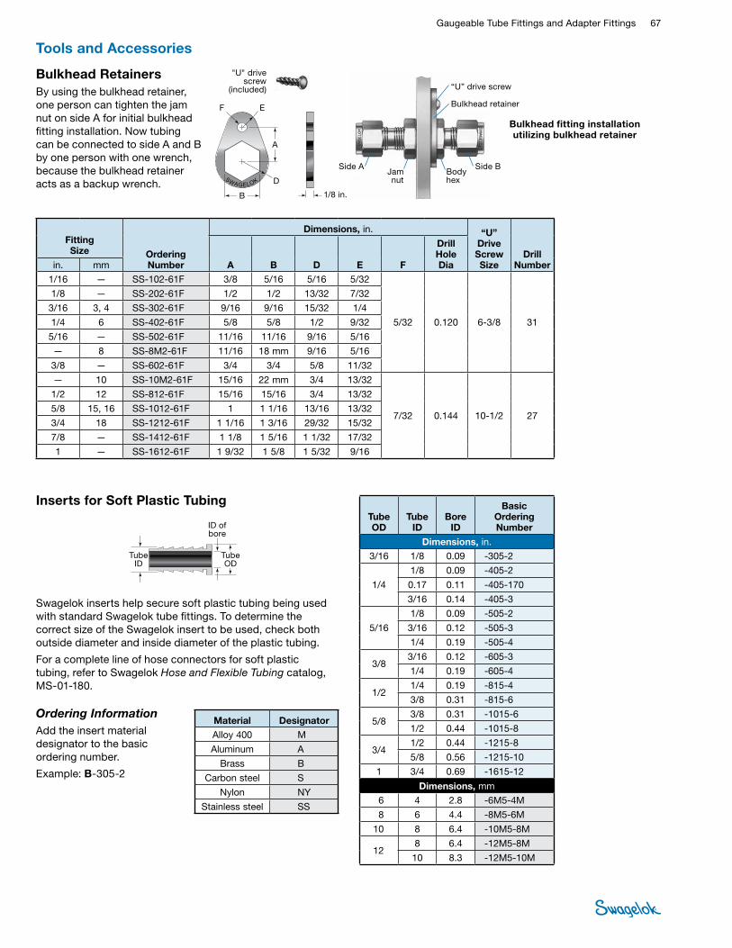
Gaugeable Tube Fittings and Adapter Fittings 67 TUBE
FITTINGS
Inserts for Soft Plastic Tubing
Ordering InformationAdd the insert material designator to the basic ordering number.
Example: B-305-2
ID of bore
Tube ID
Tube OD
Swagelok inserts help secure soft plastic tubing being used with standard Swagelok tube fittings. To determine the correct size of the Swagelok insert to be used, check both outside diameter and inside diameter of the plastic tubing.
For a complete line of hose connectors for soft plastic tubing, refer to Swagelok Hose and Flexible Tubing catalog, MS-01-180.
Tube OD
Tube ID
Bore ID
Basic Ordering Number
Dimensions, in. 3/16 1/8 0.09 -305-2
1/4
1/8 0.09 -405-2
0.17 0.11 -405-170
3/16 0.14 -405-3
5/16
1/8 0.09 -505-2
3/16 0.12 -505-3
1/4 0.19 -505-4
3/8 3/16 0.12 -605-3
1/4 0.19 -605-4
1/2 1/4 0.19 -815-4
3/8 0.31 -815-6
5/8 3/8 0.31 -1015-6
1/2 0.44 -1015-8
3/4 1/2 0.44 -1215-8
5/8 0.56 -1215-10
1 3/4 0.69 -1615-12
Dimensions, mm 6 4 2.8 -6M5-4M
8 6 4.4 -8M5-6M
10 8 6.4 -10M5-8M
12 8 6.4 -12M5-8M
10 8.3 -12M5-10M
Material Designator Alloy 400 M
Aluminum A
Brass B
Carbon steel S
Nylon NY
Stainless steel SS
Bulkhead RetainersBy using the bulkhead retainer, one person can tighten the jam nut on side A for initial bulkhead fitting installation. Now tubing can be connected to side A and B by one person with one wrench, because the bulkhead retainer acts as a backup wrench.
Bulkhead fitting installation utilizing bulkhead retainer
Side AJam nut
Body hex
Bulkhead retainer
“U” drive screw
Side B
"U" drive screw
(included)
B
A
E
D
1/8 in.
F
Fitting Size Ordering
Number
Dimensions, in. “U” Drive Screw Size
Drill Number A B D E F
Drill Hole Dia in. mm
1/16 — SS-102-61F 3/8 5/16 5/16 5/32
5/32 0.120 6-3/8 31
1/8 — SS-202-61F 1/2 1/2 13/32 7/32
3/16 3, 4 SS-302-61F 9/16 9/16 15/32 1/4
1/4 6 SS-402-61F 5/8 5/8 1/2 9/32
5/16 — SS-502-61F 11/16 11/16 9/16 5/16
— 8 SS-8M2-61F 11/16 18 mm 9/16 5/16
3/8 — SS-602-61F 3/4 3/4 5/8 11/32
— 10 SS-10M2-61F 15/16 22 mm 3/4 13/32
7/32 0.144 10-1/2 27
1/2 12 SS-812-61F 15/16 15/16 3/4 13/32
5/8 15, 16 SS-1012-61F 1 1 1/16 13/16 13/32
3/4 18 SS-1212-61F 1 1/16 1 3/16 29/32 15/32
7/8 — SS-1412-61F 1 1/8 1 5/16 1 1/32 17/32
1 — SS-1612-61F 1 9/32 1 5/8 1 5/32 9/16
Tools and Accessories

68 Tube FittingsTU
BE
FITTI
NGS
Installation InstructionsSwagelok tube fittings 1 in./25 mm and smaller can be installed quickly, easily, and reliably with simple hand tools.
Over 1 in./25 mm sizes require use of a hydraulic swaging unit to swage the ferrules onto the tubing.
Safety Precautions■Do not bleed system by loosening fitting nut or fitting plug.
■Do not assemble or tighten fittings when system is pressurized.
■Make sure that the tubing rests firmly on the shoulder of the tube fitting body before tightening the nut.
■Use the correct Swagelok gap inspection gauge to ensure sufficient pull-up upon initial installation.
■Always use proper thread sealants on tapered pipe threads.
■Do not mix materials or fitting components from various manufacturers—tubing, ferrules, nuts, and fitting bodies.
■Never turn fitting body. Instead, hold fitting body and turn nut.
■Avoid unnecessary disassembly of unused fittings.
■Use only long reducers in female Swagelok end connections.
See the instructions starting on the next page for installation of Swagelok tube fittings, O-seal male connectors, caps and plugs, port connectors, tube adapters, positionable elbows and tees, weld fittings, depth marking tool, and preswaging tool.
Tubing Considerations■Metal tubing material should be softer than fitting material.
For example, stainless steel tubing should not be used with brass fittings.
■When tubing and fittings are made of the same material, tubing must be fully annealed.
■Always use an insert with extremely soft or pliable plastic tubing.
■Extremes of wall thickness should always be checked against the suggested minimum and maximum wall thickness limitations.
■Surface finish is very important to proper sealing. Tubing with any kind of depression, scratch, raised portion, or other surface defect will be difficult to seal, particularly in gas service.
■Tubing that is oval and will not easily fit through fitting nuts, ferrules, and bodies should never be forced into the fitting.
Refer to Tubing Data catalog, MS-01-107, for additional information about tubing selection.
GaugeabilityOn initial installation, the Swagelok gap inspection gauge assures the installer or inspector that a fitting has been sufficiently tightened.
• Always depressurize a system before adjusting the tightness of a tube fitting connection.
Position the Swagelok gap inspection gauge next to the gap between the nut and body.
If the gauge will enter the gap, additional tightening is required.
If the gauge will not enter the gap, the fitting is sufficiently tightened.

Gaugeable Tube Fittings and Adapter Fittings 69 TUBE
FITTINGSSwagelok Tube Fittings Up to 1 in./25 mmThese instructions apply both to traditional fittings and to fittings with the advanced back-ferrule geometry.
Installation Instructions
Fully insert the tube into the fitting and against the shoulder; rotate the nut finger-tight. High-pressure applications and high safety-factor systems: Further tighten the nut until the tube will not turn by hand or move axially in the fitting.
Mark the nut at the 6 o’clock position. While holding the fitting body steady, tighten the nut one and one-quarter turns to the 9 o’clock position.
For 1/16, 1/8, and 3/16 in.; 2, 3, and 4 mm tube fittings, tighten the nut only three-quarters turn to the 3 o’clock position.
Swagelok Tube Fittings Over 1 in./25 mm 1. Preswage the ferrules onto the
tube using a Swagelok multihead hydraulic swaging unit (MHSU).
2. Apply the lubricant packaged with the fitting lightly to the body threads and the rear surface of the back ferrule.
3. Insert the tube with preswaged ferrules into the fitting until the front ferrule seats against the fitting body; rotate the nut finger-tight.
4. Mark the nut at the 6 o’clock position.
5. While holding the fitting body steady, tighten the nut one-half turn to the 12 o’clock position.
Use the Swagelok MHSU gap inspection gauge to ensure that the fitting has been tightened sufficiently.
Reassembly—All SizesYou may disassemble and reassemble Swagelok tube fittings many times.
• Always depressurize the system before disassembling a Swagelok tube fitting.
Prior to disassembly, mark the tube at the back of the nut; mark a line along the nut and fitting body flats.
Use these marks to ensure that you return the nut to the previously pulled-up position.
Insert the tube with preswaged ferrules into the fitting until the front ferrule seats against the fitting body.
Over 1 in./25 mm sizes: If needed, reapply lubricant lightly to the body threads and the rear surface of the back ferrule.
While holding the fitting body steady, rotate the nut with a wrench to the previously pulled-up position, as indicated by the marks on the tube and flats. At this point, you will feel a significant increase in resistance. Tighten the nut slightly.
• Do not use the Swagelok gap inspection gauge with reassembled fittings.
O-Seal Male Connectors 1. Turn the O-seal connector into the female end until it is finger-tight.
2. Tighten the O-seal connector until it makes metal-to-metal contact with the face of the female end.
3. Tighten slightly with a wrench.
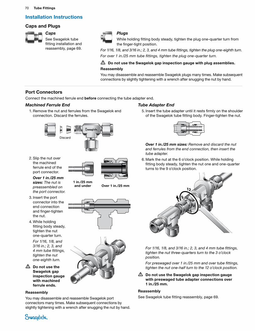
70 Tube FittingsTU
BE
FITTI
NGS
Tube Adapter End 5. Insert the tube adapter until it rests firmly on the shoulder
of the Swagelok tube fitting body. Finger-tighten the nut.
Over 1 in./25 mm sizes: Remove and discard the nut and ferrules from the end connection, then insert the tube adapter.
6. Mark the nut at the 6 o’clock position. While holding fitting body steady, tighten the nut one and one-quarter turns to the 9 o’clock position.
For 1/16, 1/8, and 3/16 in.; 2, 3, and 4 mm tube fittings, tighten the nut three-quarters turn to the 3 o’clock position.
For preswaged over 1 in./25 mm and over tube fittings, tighten the nut one-half turn to the 12 o’clock position.
• Do not use the Swagelok gap inspection gauge with preswaged tube adapter connections over 1 in./25 mm.
Reassembly
See Swagelok tube fitting reassembly, page 69.
Installation Instructions
Port ConnectorsConnect the machined ferrule end before connecting the tube adapter end.
Caps and Plugs
CapsSee Swagelok tube fitting installation and reassembly, page 69.
PlugsWhile holding fitting body steady, tighten the plug one-quarter turn from the finger-tight position.
For 1/16, 1/8, and 3/16 in.; 2, 3, and 4 mm tube fittings, tighten the plug one-eighth turn.
For over 1 in./25 mm tube fittings, tighten the plug one-quarter turn.
• Do not use the Swagelok gap inspection gauge with plug assemblies.
Reassembly
You may disassemble and reassemble Swagelok plugs many times. Make subsequent connections by slightly tightening with a wrench after snugging the nut by hand.
Machined Ferrule End 1. Remove the nut and ferrules from the Swagelok end
connection. Discard the ferrules.
2. Slip the nut over the machined ferrule end of the port connector.
Over 1 in./25 mm sizes: The nut is preassembled on the port connector.
3. Insert the port connector into the end connection and finger-tighten the nut.
4. While holding fitting body steady, tighten the nut one-quarter turn.
For 1/16, 1/8, and 3/16 in.; 2, 3, and 4 mm tube fittings, tighten the nut one-eighth turn.
• Do not use the Swagelok gap inspection gauge with machined ferrule ends.
Reassembly
You may disassemble and reassemble Swagelok port connectors many times. Make subsequent connections by slightly tightening with a wrench after snugging the nut by hand.
SWAGELOK
SWAGELOK
SWAGELOK
SWAGELOK
SWAGELOK SWAGELOK
SWAGELOK
SWAGELOK
Discard
SWAGELOK
SWAGELOK
SWAGELOK
SWAGELOK
SWAGELOK
SWAGELOK
SWAGELOK
SWAGELOK
1 in./25 mm and under Over 1 in./25 mm
9
12
3366
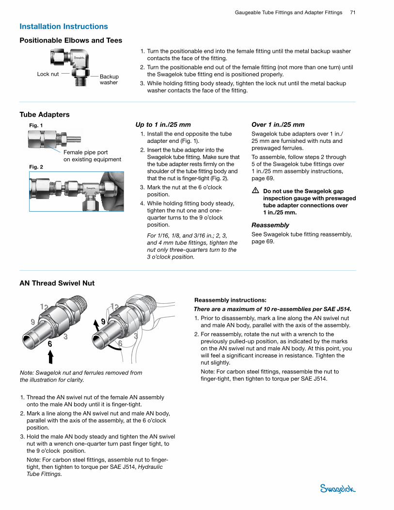
Gaugeable Tube Fittings and Adapter Fittings 71 TUBE
FITTINGS
Up to 1 in./25 mm 1. Install the end opposite the tube
adapter end (Fig. 1).
2. Insert the tube adapter into the Swagelok tube fitting. Make sure that the tube adapter rests firmly on the shoulder of the tube fitting body and that the nut is finger-tight (Fig. 2).
3. Mark the nut at the 6 o’clock position.
4. While holding fitting body steady, tighten the nut one and one-quarter turns to the 9 o’clock position.
For 1/16, 1/8, and 3/16 in.; 2, 3, and 4 mm tube fittings, tighten the nut only three-quarters turn to the 3 o’clock position.
Over 1 in./25 mmSwagelok tube adapters over 1 in./ 25 mm are furnished with nuts and preswaged ferrules.
To assemble, follow steps 2 through 5 of the Swagelok tube fittings over 1 in./25 mm assembly instructions, page 69.
• Do not use the Swagelok gap inspection gauge with preswaged tube adapter connections over 1 in./25 mm.
ReassemblySee Swagelok tube fitting reassembly, page 69.
Female pipe porton existing equipment
Fig. 1
Fig. 2
Tube Adapters
Installation Instructions
Positionable Elbows and Tees 1. Turn the positionable end into the female fitting until the metal backup washer
contacts the face of the fitting.
2. Turn the positionable end out of the female fitting (not more than one turn) until the Swagelok tube fitting end is positioned properly.
3. While holding fitting body steady, tighten the lock nut until the metal backup washer contacts the face of the fitting.
Lock nut Backup washer
AN Thread Swivel Nut
1. Thread the AN swivel nut of the female AN assembly onto the male AN body until it is finger-tight.
2. Mark a line along the AN swivel nut and male AN body, parallel with the axis of the assembly, at the 6 o’clock position.
3. Hold the male AN body steady and tighten the AN swivel nut with a wrench one-quarter turn past finger tight, to the 9 o’clock position.
Note: For carbon steel fittings, assemble nut to finger-tight, then tighten to torque per SAE J514, Hydraulic Tube Fittings.
Reassembly instructions:
There are a maximum of 10 re-assemblies per SAE J514.
1. Prior to disassembly, mark a line along the AN swivel nut and male AN body, parallel with the axis of the assembly.
2. For reassembly, rotate the nut with a wrench to the previously pulled-up position, as indicated by the marks on the AN swivel nut and male AN body. At this point, you will feel a significant increase in resistance. Tighten the nut slightly.
Note: For carbon steel fittings, reassemble the nut to finger-tight, then tighten to torque per SAE J514.
9
12
36
9
12
36
9
12
36
9
12
36
Note: Swagelok nut and ferrules removed from the illustration for clarity.
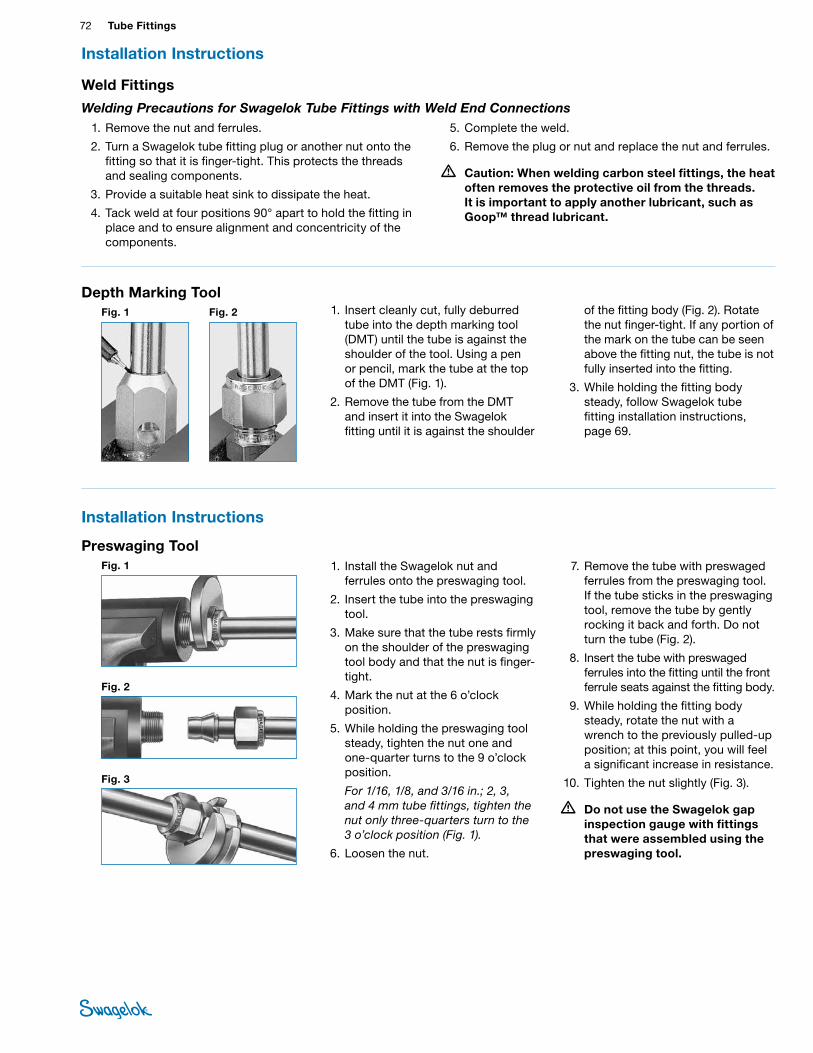
72 Tube FittingsTU
BE
FITTI
NGS
Installation Instructions
Weld Fittings
Welding Precautions for Swagelok Tube Fittings with Weld End Connections 1. Remove the nut and ferrules.
2. Turn a Swagelok tube fitting plug or another nut onto the fitting so that it is finger-tight. This protects the threads and sealing components.
3. Provide a suitable heat sink to dissipate the heat.
4. Tack weld at four positions 90° apart to hold the fitting in place and to ensure alignment and concentricity of the components.
5. Complete the weld.
6. Remove the plug or nut and replace the nut and ferrules.
• Caution: When welding carbon steel fittings, the heat often removes the protective oil from the threads. It is important to apply another lubricant, such as Goop™ thread lubricant.
Depth Marking ToolFig. 2Fig. 1 1. Insert cleanly cut, fully deburred
tube into the depth marking tool (DMT) until the tube is against the shoulder of the tool. Using a pen or pencil, mark the tube at the top of the DMT (Fig. 1).
2. Remove the tube from the DMT and insert it into the Swagelok fitting until it is against the shoulder
of the fitting body (Fig. 2). Rotate the nut finger-tight. If any portion of the mark on the tube can be seen above the fitting nut, the tube is not fully inserted into the fitting.
3. While holding the fitting body steady, follow Swagelok tube fitting installation instructions, page 69.
Installation Instructions
Fig. 1
Fig. 2
Fig. 3
1. Install the Swagelok nut and ferrules onto the preswaging tool.
2. Insert the tube into the preswaging tool.
3. Make sure that the tube rests firmly on the shoulder of the preswaging tool body and that the nut is finger-tight.
4. Mark the nut at the 6 o’clock position.
5. While holding the preswaging tool steady, tighten the nut one and one-quarter turns to the 9 o’clock position.
For 1/16, 1/8, and 3/16 in.; 2, 3, and 4 mm tube fittings, tighten the nut only three-quarters turn to the 3 o’clock position (Fig. 1).
6. Loosen the nut.
7. Remove the tube with preswaged ferrules from the preswaging tool. If the tube sticks in the preswaging tool, remove the tube by gently rocking it back and forth. Do not turn the tube (Fig. 2).
8. Insert the tube with preswaged ferrules into the fitting until the front ferrule seats against the fitting body.
9. While holding the fitting body steady, rotate the nut with a wrench to the previously pulled-up position; at this point, you will feel a significant increase in resistance.
10. Tighten the nut slightly (Fig. 3).
• Do not use the Swagelok gap inspection gauge with fittings that were assembled using the preswaging tool.
Preswaging Tool

Gaugeable Tube Fittings and Adapter Fittings 73 TUBE
FITTINGS
Caution: Do not mix or interchange parts with those of other manufacturers.
MS-01-140, RevZ, June 2019
Tubing ProductsSwagelok offers a wide variety of tubing products.
Contact your authorized Swagelok representative or see these Swagelok catalogs for more information:
■Stainless Steel Seamless Tubing, Fractional, Metric, and Imperial Sizes catalog, MS-01-181
■Ultrahigh-Purity and High-Purity Stainless Steel Tubing, Fractional, Metric, and Imperial Sizes catalog, MS-01-182
Tubing Tools and AccessoriesFor tube benders, tube preparation tools, and tube support systems, refer to Tubing Tools and Accessories catalog, MS-01-179.
Leak Detectors, Lubricants, and SealantsFor liquid leak detectors, lubricants, and sealants, refer to Leak Detectors, Lubricants, and Sealants catalog, MS-01-91.

IntroductionSince 1947, Swagelok has designed, developed, and manufactured high-quality, general-purpose and specialty fluid system products to meet the evolving needs of global industries. Our focus is on understanding our customers’ needs, finding timely solutions, and adding value with our products and services.
We are pleased to provide this global edition of the book-bound Swagelok Product Catalog, which compiles more than 100 separate product catalogs, technical bulletins, and reference documents into one convenient, easy-to-use volume. Each product catalog is up to date at the time of printing, with its revision number shown on the last page the individual catalog; for example, the Swagelok Gaugeable Tube Fittings and Tube Adapters catalog is MS-01-140, RevW. Subsequent revisions will supersede the printed version and will be posted on the Swagelok website and in the Swagelok elec-tronic Desktop Technical Reference (eDTR) tool.
For more information, visit your Swagelok website or contact your authorized Swagelok sales and service representative.
Safe Product SelectionWhen selecting a product, the total system design must be considered to ensure safe, trouble-free performance. Function, material compatibility, adequate ratings, proper installation, operation, and maintenance are the responsibilities of the system designer and user.
Warranty InformationSwagelok products are backed by The Swagelok Limited Lifetime Warranty. For a copy, visit swagelok.com or contact your authorized Swagelok representative.
Swagelok, Ferrule-Pak, Goop, Hinging-Collecting, IGC, Kenmac, Micro-Fit, Nupro, Snoop, Sno-Trik, SWAK, VCO, VCR, Ultra-Torr, Whitey—TM Swagelok Company15-7 PH—TM AK Steel Corp.AccuTrak, Beacon, Westlock—TM Tyco International ServicesAflas—TM Asahi Glass Co., Ltd.ASCO, El-O-Matic—TM EmersonAutoCAD—TM Autodesk, Inc.CSA—TM Canadian Standards AssociationCrastin, DuPont, Kalrez, Krytox, Teflon, Viton—TM E.I. duPont Nemours and CompanyDeviceNet—TM ODVADyneon, Elgiloy, TFM—TM Dyneon Elgiloy—TM Elgiloy Specialty Metals FM—TM FM GlobalGrafoil—TM GrafTech International Holdings, Inc.Honeywell, MICRO SWITCH—TM HoneywellMAC—TM MAC ValvesMicrosoft, Windows—TM Microsoft Corp.NACE—TM NACE InternationalPH 15-7 Mo, 17-7 PH—TM AK Steel Corppicofast—Hans Turck KGPillar—TM Nippon Pillar Packing Company, Ltd.Raychem—TM Tyco Electronics Corp.Sandvik, SAF 2507—TM Sandvik ABSimriz—TM Freudenberg-NOKSolidWorks—TM SolidWorks CorporationUL—Underwriters Laboratories Inc.Xylan—TM Whitford Corporation© 2018 Swagelok Company
Caution: Do not mix or interchange parts with those of other manufacturers.