tapered acoustical directional couplers for integrated acousto-optical … · 2017-02-28 · 364...
TRANSCRIPT
364 JOURNAL OF LIGHTWAVE TECHNOLOGY, VOL. 13, NO. 3, MARCH 1995
Tapered Acoustical Directional Couplers for Integrated Acousto-Optical Mode Converters with Weighted Coupling
Harald Herrmann, Ulrich Rust, Student Member, ZEEE, and Klaus Schafer
Abstract-Weighted coupling for strong sidelobe supprkion of integrated acoustooptical mode converters in LiNbOs using acoustical directional couplers has been studied theoretically and experimentally. A parameter free model for the propagation of surface acoustic waves in guiding structures has been developed based on a step-like variation of the acoustic velocity. Comparisons of theoretical results with experimental ones for acoustic waveguides and directional coupler structures confirm the applicability of the model. A coupled mode description of the acousto-optical polarization conversion in converters with acoustical directional couplers has been developed and applied to several tapered acoustical directional couplers. The model reveals that the conversion characteristics are usually strongly asymmetric. If the directional coupler is appropriately designed, a sidelobe suppression of about 30 dB can be achieved. First experimental results with tapered directional couplers confirm within some limits the theoretical predictions.
I. INTRODUCTION
UNABLE wavelength filters and wavelength selective T switches are key components for a variety of applications especially in wavelength division multiplexed (WDM) optical communication systems and for optical instrumentation. In particular, integrated acousto-optical filters and switches [ 11, [2] in LiNbOs are very attractive as they offer a broad tuning range [3], [4], a fast tuning speed [5] and especially their unique property of simultaneous filtering capability [6].
These devices consist of a combination of collinear acousto- optical polarization converters and polarizing elements, e.g., polarization splitters andor polarizers. The principle of opera- tion of the acousto-optical polarization converters is based on an interaction of guided optical fields of orthogonal polariza- tion and a surface acoustic wave (SAW). Via this interaction a polarization conversion is achieved, if the phase-matching condition is fulfilled. It requires that the difference of the wave vectors of the optical waves is compensated by the SAW wave vector. Usually, the mode conversion is achieved with a homo- geneous coupling strength along the interaction length due to a (nearly) constant SAW intensity, either guided in an acoustical waveguide or even unguided. In these cases the resultant conversion characteristics, i.e., the power of the converted optical wave as function of the optical Wavelength, are sinc2-
Manuscript received June 14, 1994; revised December 5, 1994. This work was supported in part by the Research Institute of the German TELEKOM and by the European Union within the RACE-project R 2028 “MWTN.”
The authors are with the Universiat-GH Paderborn, Angewandte Physik, D-33095 Paderborn, Germany.
IEEE Log Number 9409167.
0733-8724/95$04
like functions with sidelobes theoretically -9.7 dB below the maximum conversion leading to a significant contribution to crosstalk especially in dense WDM systems.
To reduce the sidelobes two different approaches have been investigated: cascading of several devices [7]-[ 101 and using a weighted coupling technique [11]-[16]. The first approach requires more complex devices and it is not directly applicable to switch structures. Moreover, cross talk due to coherent channel interference [17], [ 181, which occurs if simultaneous filtering is applied, is not suppressed within such structures. This is especially significant if the cascading is combined with birefringence apodization as discussed in [ 101.
The second concept to reduce the sidelobes relies on a locally varying coupling coefficient. As the conversion char- acteristics are approximately given by the square magnitude of the Fourier transform of the coupling strength, weighted coupling can be achieved, if the coupling strength is tapered within the interaction length with a soft onset and cutoff at the beginning and at the end of the structure, respectively. Such weighted techniques-also called apodization-are well known in several areas of engineering. In integrated optics apodization has been used for instance in Bragg reflection type grating filters [ 191 and electro-optical wavelength filters [20].
Weighted coupling for acousto-optical mode converters has been demonstrated by exciting focused SAW’s by specially matched transducer electrodes [ 131, [ 151, with acoustical waveguides of varying widths [14], or with acoustical directional couplers [ l l ] , [12]. The latter structure uses a sinusoidal weighting of the coupling strength achieved with a directional coupler structure with constant gap. However, more sophisticated integrated acoustic structures promise a further sidelobe suppression. One approach is to taper the directional coupler [21] as shown in Fig. 1. Such devices will be discussed in detail in this paper.
We present a detailed analysis of acousto-optical mode converters with tapered acoustical directional couplers. A model for the propagation of SAW’s in integrated acoustical structures will be developed and compared with experimen- tally obtained results in Section 111. The coupled mode for- malism will be extended to acousto-optical mode converters with acoustical directional couplers; a few examples will be discussed in detail and again comparison with experimental results will be performed in Section IV. To collect data on fabrication conditions and characterization methods a brief description of them will be given in Section 11.
.OO 0 1995 IEEE

HERRMA” et al.: TAF’ERED ACOUSTICAL DIRECTIONAL COUPLERS 365
transducer tapered gap
Fig. 1. Basic structure of an integrated acousto-optical mode converter with tapered acoustical directional coupler.
Fig. 2. Cross-sectional view of an acoustical waveguide and the correspond- ing velocity profile for the SAW calculations.
n. FABRICATION AND CHARACTEREATION OF INTEGRATED ACOUSTO-OPTICAL DEVICES
In this section a brief review of the techniques used to fabricate the acousto-optical devices is given and the char- acterization methods to study them are discussed.
As substrate material we used (optical grade) X-cut, Y- propagating LiNbO3. Acoustical waveguides have been fab- ricated via Ti-indiffusion into the cladding regions of the acoustical guide or the acoustical directional couplers (see Fig. 1). For all the devices discussed below, 1600-A-thick titanium layers have been indiffused. This diffusion has been performed at 1060°C during 24 h. Afterwards, optical waveguides have been fabricated by an indiffusion of 7-pm-wide Ti-stripes during typically 9 h at 1030°C. These parameters yield single mode optical waveguides for both polarizations in the spectral range around A = 1.55 pm.
For the excitation of surface acoustic waves either bi- directional (10 finger pairs) or unidirectional transducer elec- trodes (2 x 5 finger pairs separated by a quarter of the acoustical wavelength) for the frequency range around 170 MHz have been vacuum deposited on the substrate. The overlapping width of the transducer fingers is 140 pm.
To study the performance of the acoustical waveguide structures a laser probing technique has been used [22]. A He-Ne-laser beam is focused on the surface where a small part of the beam is diffracted due the surface corrugation grating induced by the SAW. By measuring the intensity of the diffracted light as a function of the position on the surface the intensity profile of the SAW can be determined.
Moreover, the laser probing technique allows to determine the SAW velocity by measuring the diffraction angle. From this angle the grating period and, hence, the acoustical wave-
length can be deduced. Via the known acoustical frequency the phase velocity can be determined. Using this method we have measured the SAW velocities in undoped and in planar diffused Limo3. From these experiments we found that the velocity of the SAW is increased by 0.31% in the diffused material fabricated with parameters given above.
The characterization of the acousto-optical mode conversion has been performed by either using a DFB-laser (A M 1.55 pm) as light source and measuring the transmission through the device as a function of the frequency of the SAW or by using a broadband LED measuring the spectral properties of the transmitted light at a fixed acoustic frequency.
111. ACOUSTICAL WAVEGUIDES AND DIRECTIONAL COUPLERS
A. lleoretical Model As the Ti-indiffusion increases the SAW velocity, acoustical
waveguide structures can be fabricated by an indiffusion into the cladding regions of the guides. According to our knowl- edge there exists no accurate description for such waveguides allowing an explicit calculation of waveguide properties. An analysis starting from the wave equation using numerical methods such as e.g., finite element methods would require a profound knowledge of the changes of the elastic and piezo- electric properties due to the Ti-diffusion in order to get the two-dimensional “index profile” for the acoustic waveguide. As these data are not available we have pursued another concept to model the acoustical waveguide structures.
The procedure is similar to the case of optical stripe waveguides. A SAW in a piezoelectric material like LiNbO3 is completely described by four components: the amplitudes (and phases) of the elongations along the three crystal directions and the electric potential. For X-cut, Y-propagating SAW’S the amplitude of the elongation parallel to the crystalline X- direction is dominant [23]. Therefore, we assume that the SAW can be described reasonably well in a scalar approximation by regarding only this component. Similar to the effective index model for optical stripe waveguides [24] a compression to a one dimensional problem can be made using a one dimensional velocity profile, too. This profile is obtained from the measured SAW-velocities as described in the preceding section, i.e., we assume a velocity profile as shown in Fig. 2 with constant velocities within the undoped (vo) and within the doped regions (vT~). In that case the transversal wave equation for acoustical waveguide structures reduces to:
urn(.) is the transversal field distribution of the amplitude of the elongation along the crystalline X-axis of the rn-th mode, v , ~ , ~ denotes its propagation velocity. The function U(.) is the velocity profile across the waveguide structure, faC is the frequency of the SAW.
This equation can be easily solved if we further assume that U,(Z) and its first derivative are continuous at the boundaries. With these assumptions a model free of any fit parameter is given which can be applied to describe various

366 JOURNAL OF LIGHTWAVE TECHNOLOGY, VOL. 13, NO. 3, MARCH 1995
- c 5 3690
I
100 200 3680 1,
width [pm]
+IO0 pm(exp.)
W=120pm
W=70pm 20
10
0- 40 80
gap width bm] Fig. 3. Calculated SAW velocities for guided modes in an acoustical waveguide. (fa= = 170 MHz.) Fig. 4. Calculated and measured coupling lengths of acoustical directional
couplers with acoustic waveguides of various width.
coupled in one of the waveguides- Therefore, LC is given by acoustical waveguide structures. To test the validity of the model calculated results for straight waveguides and couplers
sections. (2) will be compared with experimental results in the subsequent veff ,o veff ,1
B. Straight Acoustical Waveguides Using the model and the experimentally determined SAW
velocity change the propagation characteristics of guided acoustical waves can be calculated. In Fig. 3 the calculated velocity of the fundamental and of the first higher order mode is shown as function of the waveguide width, i.e., the width of the undiffused region. The frequency of the SAW was taken to be 170 MHz. Below about 130 pm width the acoustical waveguide is single mode, whereas at larger widths a second mode is supported.
By studying experimentally the intensity profile of the guided SAW using again the laser probing technique we observed that waveguides up to about 130 pm width are single mode. In waveguides with larger widths the intensity profile shows some periodic oscillations along the propagation direction which must be the result of an interference between two guided modes. The period of the oscillation is about 10 mm; this corresponds well with the beat length of the interfering fundamental and first order modes with a velocity difference of about 7 d s as predicted from the theoretical model (see Fig. 3).
C. Acoustical Directional Couplers of Constant Gap
An acoustical directional coupler is formed by two closely adjacent acoustical waveguides which are separated by a small Ti-indiffused gap. If a SAW is excited in one of the waveguides the acoustical power couples periodically between the two guides. The coupling strength and the periodicity is determined by the waveguide dimensions and the gap between the guides.
Using the theoretical model such an acoustical directional coupler can be described in analogy to the analysis of optical directional couplers in the framework of super modes [25]. In the coupler two acoustical super modes-an even and an odd mode-are guided with velocities Veff,o and Veff,l, respectively. The coupling properties result from their interfer- ence. The coupling length L,, i.e., the length after which the acoustical power is completely coupled to the adjacent guide, can be calculated from the relative phase shift A$ between the two modes, which is a multiple of T if the power is completely
In Fig. 4 the calculated coupling length as function of the gap width is shown for several widths of the acoustical guide. Coupling is stronger for narrower acoustical guides. A detailed analysis of the curves reveals that the coupling length varies nearly exponentially with the gap width, i.e., L, = LO exp(yg), where g is the width of the gap and LO and y are constants depending only on the waveguide parameters. Only for narrow waveguides (70 pm) there is a significant deviation from the exponential behavior. For a waveguide width of 100 pm LO = 6.08 mm and y = 0.01785 pm-', for 110 pm wide guides LO = 6.724 mm and y = 0.01839 pm-' and for 120 pm wide guides LO = 7.45 mm and y = 0.01886 pm-'.
We have also studied experimentally the coupling length in directional couplers with 70- and 100-pm-wide waveguides and gaps of 20 and 40 pm [ 111. The results are shown in Fig. 4 as well. There is a tendency that the theoretical model predicts shorter coupling lengths than experimentally observed. For the 40 pm gap the deviation is about 20%, whereas it is below 10% for the 20-pm gaps. Whether there is a systematic deviation for larger gaps cannot be decided as long as more experimental results are not available.
In [ 121 the exponential variation of the coupling length as function of the gap has been analyzed experimentally even for larger gaps. The authors calculated from their experimental data LO = 6.8 mm and y = 0.021 pm-'. However, they used slightly different fabrication conditions for the acoustical couplers. Therefore, a comparison of their results with our model should not be overemphasized. But again, it seems that for relatively small gaps the results correspond reasonably well with the model whereas at larger gaps there is a significant deviation. For instance, they observed a coupling length of 55 mm for 100 pm and our model predicts only 36 mm.
D. Tapered Acoustical Directional Couplers
An acoustical directional coupler can be tapered, i.e., one of its dimensional parameters varies along the coupling length. The simplest tapering scheme is to vary the gap of the coupler, which will be discussed in this section. To apply the device in an acousto-optical mode converter the overall structure should

HERRMANN et al.: TAPERED ACOUSTICAL DIRECTIONAL COUPLERS
yield a complete coupling period. The coupling strength should be strong in the middle of the structure and reduced toward the outer regions.
For the design of such tapered acoustical directional cou- plers the theoretical model can be used. The coupling behavior is again determined by the interference of the two super modes of the waveguide structure. However, in the case of the tapered coupler the velocities and the field distributions of these modes become explicit functions of the propagation coordinate z as the waveguide geometry varies with z ; i.e., we perform a local normal mode analysis of the coupler structure as usually done for tapered optical directional couplers [25]. The accumulated phase difference between the two modes is given by
where the integral must be performed along the coupler structure. More precisely, the integral must be evaluated along a path s (z ) which is defined by the z-dependent midpoint be- tween the two acoustical guides. Thus, (3) can be transformed to
x {l + ( w ) 2 d z ' . (4)
L is the overall length of the coupler structure starting at -L/2. If only the gap varies and not the width of the two acoustical waveguides the exponential relation between coupling length and gap can be used and (4) becomes:
with g(z ) describing the gap function. Because the geomet- rical variation of the coupler structure should be adiabatic,
Using this model a tapered directional coupler of an arbi- trary gap variation can be designed. For practical purposes, however, the structures should be as simple as possible. Therefore, we restrict our discussion to tapered directional couplers consisting of three segments, two branching segments and a central section. The central section is formed by a directional coupler with constant gap, whereas in the branching segments the gap is a function of z. Furthermore we restrict our discussion to symmetric structures, i.e., the tapering in the incoming branch is the same as in the outgoing branch. The simplest structure consists of a linear taper in the branches, i.e., the gap linearly increases from both ends of the central section. Two different types of such couplers have been analyzed as shown in Fig. 5: In the first structure both acoustical waveguides are tilted in the branching segments with respect to the central section. In the second type one acoustical waveguide goes straight through the whole structure, whereas the other one is tilted in the branching segments. The latter structure is more appropriate for acousto-optical mode convert- ers as the optical waveguide can be embedded in the straight
<< 1 and hence is neglectable.
367
type I
type I1
G A ' W =< 2W I I
(b)
Fig. 5. The two different types of tapered acoustical directional couplers.
acoustical guide with a constant distance to Ti-indiffused cladding regions thus avoiding coupling of the optical waves into the claddings and hence additional losses of the optical waves.
Results from the theoretical model will be discussed in comparison with experimental results. We have fabricated tapered directional couplers of both types with dimensional parameters as follows: A type I directional coupler with a central section of length L, = 3.45 mm and zero gap. A linear taper from 0 to 55 pm over a length of Lt = 6.875 mm in the outer sections. The width of the acoustical waveguides is 100 pm. (Actually, to avoid problems with the lithography we have omitted the sharp peak of the gap between the outer segments and the central regions and cut the gap abruptly at 5 pm width. Therefore, in the beginning of the branching sections we have a slightly wider waveguide as in the central section instead of two waveguides separated by a very small gap.) As an example of a type I1 coupler we used a structure consisting of 110 pm wide waveguides and a central section length L, = 5.39 mm. The gap increases to 70 pm over a length of Lt = 6.88 mm.
The coupling properties of these tapered directional couplers have been investigated using the laser probing technique. On the left hand side of Fig. 6 the measured intensity profile of the SAW for the coupler of type I is shown as a topographic plot. One can clearly see the coupling behavior within the structure. The SAW power excited in the right waveguide at z = 0 mm is coupled into the adjacent guide and back again. Complete coupling has been obtained within the structure slightly shorter than the overall length. On the right hand side of Fig. 6 the SAW intensity distribution obtained from calculations using the theoretical model is shown. By defining the center position x, of the intensity distribution according to
XC =/ XI SAW^^// I S A W ~ X (6) cross section cross section

368 JOURNAL OF LIGHTWAVE TECHNOLOGY, VOL. 13, NO. 3, MARCH 1995
3 U
N
-200 0 200
[Pml
-200 -100 0
xc [Pml
-200 0 200
[Pml Fig. 6. Contour line plots of the measured (left) and calculated (right) intensity distribution of the tapered directional coupler of type I (Levels lo%, 20%. . . ., 90% of the maximum intensity). The shaded areas indicate the Ti-diffused regions of the coupler structure. The diagram in the middle shows the center of the intensity distribution determined from the experimental distribution (solid line) and the theoretical distribution (dashed line).
- Y 8 N
-400 -200 0
= P m l
-200 -100 0 -400 -200 0
xc [Pml [ccml Fig. 7. Contour line plots of the measured (left) and calculated (right) intensity distribution of the tapered directional coupler of type II (Levels 10%. 20%. . . ., 90% of the maximum intensity). The shaded areas indicate the Ti-diffused regions of the coupler structure. The diagram in the middle shows the center of the intensity distribution determined from the experimental distribution (solid line) and the theoretical distribution (dashed line).
a further comparison of the measured results with the theoret- ical model is possible. (ISAW is the SAW intensity and x the coordinate in transversal direction.) In the middle diagram of Fig. 6 x, is shown as a function of the propagation distance z. The solid line belongs to the measured and the dashed line to the calculated results. From the theoretical model a slightly weaker coupling is expected. The theoretical coupling length is about 1 mm larger than the measured one of 8 mm.
In Fig. 7 the results obtained for the coupler of type I1 are shown. This coupler has a coupling length of about 9.5 mm. The results from the theoretical model coincide very well with the measured ones as can be clearly seen from the variation of the center position in the middle diagram in Fig. 7.
Why the modeling of the coupler of type I1 agrees far better with the experimental results than that for the type I coupler is not yet clear. One of the differences of these two structures is the width of the acoustical waveguides. It may
be that the theoretical model for the acoustical waveguides is better appropriate for wider waveguides.
The two examples presented in this section for tapered couplers together with the results for directional couplers and straight waveguides demonstrate that the model for SAW propagation can be successfully applied to study guiding struc- tures theoretically. Of course, there are still some deviations between theory and experiment; however, even without a refinement of the model a more than qualitative understanding of such structures has been achieved.
IV. ACOUSTO-OFTICAL POLARIZATION CONVERTERS
A. Theoretical Model Acousto-optical mode conversion with weighted coupling
has been treated theoretically by using matrix formalism in [14]-[16], [26]. The authors assumed a locally varying

HERRMANN et al.: TAPERED ACOUSTICAL DIRECTIONAL COUPLERS 369
coupling coefficient along the interaction length but neglected effects related to different phase-matching conditions if several acoustic modes are involved. In this section we present a generalized approach to describe the weighted acousto-optical polarization conversion in tapered acoustical directional cou- plers.
Polarization conversion can be described using the well- known coupled-mode formalism [27], [28]. However, for the general case of the mode converter with tapered acoustical directional couplers some modifications of the commonly used coupled mode equations are necessary. Using again the model of the super modes for the acoustical directional couplers two of them-the even and the odd mode-are involved in the conversion process. Both modes contribute to the conversion process with acousto-optical coupling strengths ~1 and K Z ,
respectively. Let A and B denote the amplitudes of the optical modes of TE and TM polarization, respectively, the coupled differential equations can be written as:
d A - = -K;Bexp( - i$ l ( z ) ) - d j B e x p ( - i $ z ( z ) ) dz (7)
d B 8.2 - = KlAexp( i$ l ( z ) ) + KZAexp(i$z(z)) (8)
where z is the propagation direction and the phase terms $1 (z) and $z(z) describe the phase-mismatch. Due to the tapering of the directional coupler the SAW-velocity of the two acoustic modes and hence their wave vectors vary along the interaction length. To take this effect into account, $i must be calculated in the following form:
(9) X is the optical wavelength and An is the difference of the effective refractive indices of the TM- and TE-polarized optical modes. Kac,i is the-projection of the acoustical wave vector onto the propagation axis. In type I directional couplers the direction of the propagation of the super modes is parallel to the z-axis as the structure is symmetric with respect to the z-direction. For type II couplers, however, only one arm is tilted in the branching segments. Therefore, we assume that the propagation direction of the super modes is tilted by half the branching angle. In a tapered directional coupler Kat,; is an explicit function of the coordinate z. (Moreover, even An may be a function of z if inhomogeneities of the optical waveguide structure or a temperature gradient are present in the device [29], [30]. In the following such inhomogeneities will not be discussed and therefore a z-dependence of An can be neglected.) $o,i are the initial phases of the acoustical waves at the beginning of the interaction; the phase difference A$o = $0,1 - $ 0 , ~ together with the wave vectors of the acoustical modes determine the interference pattern within the coupler structure.
If the losses of the acoustical waves can be neglected )il and K Z are real coupling constants; all phase contributions are taken into account by the phase functions $i. ~ 5 , ~ are proportional to the acoustic power density of the respective mode at the location of the optical waveguide.
By introducing the sum and the difference of the coupling coefficients according to
and for the phase functions
with the effective wave vector Kac,eff = (Kac,1 + Kac,2)/2 and the difference AK,,eff = (Kac,l - Kac,2)/2 the coupled mode equation system can be written as:
d A - = - [~cos(A$(z)) - iAl~sin(A$(z))]Bexp(-i$(z)) dz
(13)
- = +[~.cos(A$(z)) + iA~sin(A@(z))]A exp(+i$(z ) ) . d B dz
(14)
This equation system can be transformed to the usual form of the coupled mode equations
- = -K&(z) B exp( - i$ ( z ) ) d A a z
if one defines an effective coupling strength according to
fie&) = ~ c o s ( A $ ( z ) ) + iAKsin(A$(z)). (17)
In the general case ~ ~ f f becomes a complex function of z with a nonvanishing imaginary part.
For the special case of an acoustical directional coupler with constant gap and with the same amplitudes of the acoustical waves at the location of the optical waveguide, i.e., ~1 = 6 2 , the imaginary part of tseff vanishes. Moreover, the interference of the two super modes at the location of the optical waveguides at the beginning of the structure is destructively, i.e., A$o = 7r, because the SAW’S are excited in the adjacent acoustical waveguide. The result is a sinusoidal weighting of the coupling for this structure. For tapered couplers, however, the situation is more difficult. The complex nature of K has to be taken into account. Some special examples will be discussed in the next section.
B. Effective Coupling Strength and Conversion Characteristics To study the conversion characteristics of acousto-optical
mode converters a few examples will be discussed. In Fig. 8 four structures are shown. All these couplers have been designed using the theoretical model for the SAW. The dimen- sions are chosen to yield a complete coupling period within the overall structure. The first one (A) is a directional coupler with 20-pm constant gap and an overall length of 17.365 mm. The second structure (B) is a tapered coupler of type I with a maximum gap of 55 pm and zero gap in the central section.

370 JOURNAL OF LIGHTWAVE TECHNOLOGY, VOL. 13, NO. 3, MARCH 1995
10
........... .............. 5 - L - 'E
,E v
0 -
E - 17324 -5
(b) - in
I I I
-
1 I I I
100
1 5 .
- 1 0 ' - 'E
f 5 .
5
Y
1g 0
9 -5
13032 13032
26064
(d)
Fig. 8. Structure and dimensions of the four acoustical directional couplers for acousto-optical mode converters. The dotted line denotes the position of the optical waveguide.
'
'
The tapered coupler (C) is of type I1 with 70 pm gap at the outer ends and again a central section with zero gap. Please note that the structures B and C are similar to the couplers already discussed in Section 111-D; however, their dimensions have been slightly modified to achieve the optimum coupler performance according to the theoretical model. The structure D is a tapered coupler of type II. Its central section length is zero and the gap starts with 100 pm. This results in a relatively long overall length of 26.064 mm.
The SAW intensity distributions have been calculated for the four structures. We have assumed that the power guided in both super modes is equal. This is reasonable if the gap between the two waveguides is large at the location of the transducer. In that case the two modes are nearly degenerate and their field distributions are nearly the same at the location of the transducer. A small fraction of the SAW power is excited in radiation modes, but it is leaked out of the interaction regime thus conversion induced by these modes can be neglected.
From the intensity distribution the effective coupling strength at the'location of the optical waveguide, which is
I I I I -10 0 10
Fig. 9. Real part (upper diagram) and imaginary part (medium diagram) of the effective coupling strength versus the interaction length for the four acoustical directional couplers. The lower diagram shows the variation of the effective wave vector along the structure.
-10 ' = [mml
indicated by the dotted line in Fig. 8, has been determined. (Due to the presence of a Ti-indiffused optical waveguide within the structure, the properties of the acoustical directional coupler may be slightly changed. However, we have neglected this effect.)
In Fig. 9 the effective coupling strengths as function of the propagation coordinate z for the four structures are shown. Furthermore, the variations of the effective acoustic wave vec- tor Kac,eff from its average value KaC+ff have been calculated. The real part of ~ , ~ f f increases from zero toward the middle of the structure and after that decreases again symmetrically to zero. For structure A it is a sinusoidal function whereas for the other structures the slope at the beginning is smaller. The maxima of the imaginary parts are about 2.5% to 5% of the maxima of the real parts of y i , ~ . The only common behavior for all structures is the zero crossing in the middle of the interaction length. The effective acoustical wave vector decreases slightly toward narrower gaps until it reaches a minimum and increases again. In the central section Kac,eff is constant. However, although there is some variation of Kac,efi within the overall structure, it is generally relatively small. The maximum variation for structure C is only about 5 x of the average value.
The conversion characteristics for the four structures have been calculated; the results are shown in Fig. 10. The power of
-1 II v , I

HERRMANN ef al.: TAF'ERED ACOUSTICAL DIRECTIONAL COUPLERS 37 1
0
- m TI v
-20 .- E F 0
- 40
0
- m D Y
g -20 .- E W
0
-40
-10 -5 0 5 10 -10 -5 0 5 10
[nml [nml Fig. 10. Conversion characteristics of the mode converters with the four different acoustical directional couplers.
the converted wave is shown as function of the deviation from the wavelength of maximum conversion. The frequency for the SAW has been adjusted to yield this maximum conversion at a wavelength of X = 1.55 pm. To achieve complete mode conversion at AA = 0 the amplitudes of the effective coupling strength must be chosen as given by data in Fig. 9.
The conversion characteristic for the structure A has a full width at half maximum of FWHM = 1.9 nm and it is nearly symmetric with a sidelobe suppression of - 16.8 dB. However, a slight asymmetry occurs as the main sidelobe on the left hand side is about 1.3 dB higher than that on the right hand side. This is due to the fact that the amplitudes of the even and odd SAW modes are not exactly equal at the location of the optical waveguide; they differ by about 4% as can be deduced from the imaginary part of &,E. The asymmetry is not caused by a variation of the acoustic wave vector and therefore variation of the phase-matching condition along the structure.
For the structures B and C the half widths are 2.1 and 1.9 nm and the highest sidelobes are at -20.1 and -21.8 dB, respectively. Both curves are strongly asymmetric. For B the sidelobes occur at shorter wavelengths whereas for structure C the dominant sidelobes are on the long wavelength side. Two contributions are responsible for the asymmetry of the curves: The effect of unequal amplitudes of the even and odd SAW modes leading to a nonvanishing imaginary part of and the variation of the acoustic wave vector along the interaction length. By calculating the conversion characteristics for the structure C assuming no variation of acoustic wave vector or a vanishing imaginary part of we found that the main contribution to the asymmetry comes from the unequal amplitudes of the SAW modes. Therefore, it can be understood why the main sidelobes occur left or right relative to the main transmission for structures B and C. Calculations of the mode profiles show that there is a larger amplitude at the location of the optical waveguide of the odd mode for structure B at the
- m
.- 0 e
U
C Y
> 0
[nml Fig. 11. Conversion characteristics of the mode converter with acoustical directional coupler C. The two curves shows the characteristics for optical waveguides laterally shifted 20 pm toward the adjacent acoustical guide (dashed line) and 20 pm away from it (solid line), respectively.
beginning of the interaction leading to a negative imaginary part while the situation for structure C is vice versa.
The strongest sidelobe suppression is obtained with structure D. The highest sidelobe is at -29.1 dB; the half width is 1.5 nm. The curve shows long period oscillations at the short wavelength side whereas for larger wavelengths the oscillation periods are shorter. However, all sidelobes are kept to a very low level.
As the main sidelobes for structures B and C appear on opposite sides of the conversion characteristics, an optimized structure may be a compromise between a type I and a type II coupler. Therefore, we have made some calculations for such structures. We modified the coupler C in such a way that the gap remains 70 pm at the outer ends but the arm with the optical waveguide is slightly tilted in the branching segments. With a tilting of 0.13', i.e., the waveguide center position is laterally shifted 16 pm along the branching segment, the main sidelobes of the calculated conversion characteristics are below -31 dB on both sides of the main transmission peak.
Another interesting feature for applications is to incor- porate more than one optical waveguide within the same acoustic guide. This is especially interesting for polarization independent devices realized by polarization diversity. As an example for such a situation the conversion characteristics for two optical waveguides laterally shifted +20 and -20 pm, respectively, in structure C have been calculated as shown in Fig. 11. (-20 pm means in direction to the adjacent acoustical guide, +20 pm away from it.) The SAW power for optimum conversion differs for the two guides by about 20%. For the calculation the average value of both has been chosen. The calculations reveal that there is a shift of about 0.4 nm for the wavelength of maximum conversion. The conversion characteristic for the inner waveguide (-20 pm) has slightly higher sidelobes on the short wavelength side whereas the characteristic for the outer waveguide shows pronounced sidelobes at the long wavelength side.
C. Comparison with Experimental Results Experimental investigations on acousto-optical mode con-
verters with tapered directional couplers have been performed with the two structures already discussed in Section 111-D.
A sample with the directional coupler of type I has been characterized by measuring the converted power versus the
1- ,-- 1 ' 1 1

372 JOURNAL. OF LIGHTWAVE TECHNOLDGY, VOL. 13, NO. 3, MARCH 1995
I I I I I
C
.-
I I I I I I I I
-1 0 1 -1 0 1
Afac [MHzI Afac [MHzI Fig. 12. Converted power versus acoustical frequency variation of a mode converter with acoustical directional coupler type I. Measured results are shown by the solid lines. The left result has been obtained without heating, the right with additional heating of the sample. The dotted lines shows the calculated characteristics.
acoustical frequency. In the left diagram of Fig. 12 the result of such a measurement is shown by the solid line. On the low frequency side a pronounced sidelobe of about -10 dB occurs. Such sidelobes very often occur in weighted coupling mode converters as well as in converters with homogeneous coupling strength. The origin of these sidelobes are mainly inhomogeneities especially of the optical waveguide [29], [30]. Due to these inhomogeneities there is a variation of the birefringence and hence of the phase-match condition along
pol.-
mput 1 L 4
input z
the interaction length. To suppress these sidelobes due to the unknown waveguide inhomogeneity we used a heating wire above the optical waveguide to induce a temperature profile along the interaction length to compensate the birefringence variation by taking advantage of the temperature dependence of the extraordinary refractive index of LiNbOs. In the right diagram in Fig. 12 the measpred conversion characteristic with the heating is shown. The main sidelobe could be reduced to
In both diagram-s the theoretical conversion curves are additionally shown as dashed lines. For the calculations no variation of the birefringence has been assumed. But, even for the heated sample, there are still some residual inho- mogeneities. Therefore, one cannot expect to find an exact matching of the theoretical and experimental results. However, from the theory a sidelobe of about - 16 dB is predicted on the low frequency side of the conversion curve. For the case of the heated sample a slightly smaller sidelobe has been measured.
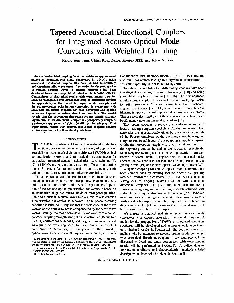
The tapered acoustical directional coupler of type II already discussed in Section III-D has been used in a polarization independent single stage wavelength filter [2 13, which is shown in Fig. 13. The filter consists of the tapered acoustical coupler with two optical waveguides embedded in one arm. At the beginning and at the end of the device there are integrated optical polarization splitters routing TM-polarized modes to the bar-state and TE-polarized waves to the cross-state. Details on the filter performance are given in [21].
We have measured the conversion characteristics of the mode converter by coupling TM-polarized broadband light from a LED into the input ports 1 or 2, thereby passing the con-
-17 dB.
Fig. 13. length filter with a tapered acoustical directional coupler of type II.
Structure of the polarization independent integrated optical wave-
verter through the outer or inner waveguide, respectively. The measured characteristics are shown in Fig. 14. The conversion curve for the inner waveguide has higher sidelobes; its largest sidelobe is at -15 dB. The sidelobes on the long wavelength side are higher for both curves. The dashed lines in the diagram are the calculated conversion characteristics. From the theory a stronger sidelobe suppression is expected. The discrepancies can again be explained by remaining inhomogeneities in the structure. Moreover, the situation for this device is more complex. The polarization splitters typically have an extinction ratio of 18-20 dB [9]. Therefore, a small fraction of the incoupled wave is routed the “wrong” way through the device. This may contribute as well to some deviations from the theory. However, the tendency that larger sidelobes occur at the long wavelength side is confirmed.
As discussed in the last section a shift of the maximum transmission peak between the two curves is expected. Ac- tually, we observed a shift of about 0.3 nm. However, the observed shift is toward longer wavelength for the inner guide, whereas a situation vice versa is expected from the calculations. There may be several reasons responsible for this discrepancy. The two optical waveguides may not be identical. As discussed in [29] there is a strong dependence of the effective birefringence An from the fabrication parameters. For instance the variation with waveguide width W is given by dAn/dW w -3 x pm-l, i.e., if the widths of the two optical waveguides differ by only 0.1 pm, the wavelength
I I 1 ’ 1 I
HERRMANN et al.: TAPERED ACOUSTICAL DIRECTIONAL COUPLERS 313
I I I
inner n 0
n
U
c 0
a, c 0
m -10 U
.- p -20
-30
-An 1560
r ”
1550
[nml
I I I
1550 1560
Fig. 14. The dashed lines show the calculated responses.
Measured filter characteristics for the inner (left) and outer (right) waveguide of the polarization independent single
for exact phase-matching is shifted by about 0.6 nm. As the accuracy of the photomasks for the fabrication of such integrated optical circuits are typically in the order 0.1 pm, there may already be a difference of the widths of the two waveguides leading to an additional shift of the conversion characteristics.
V. CONCLUSION We have studied tapered acoustical directional couplers
for integrated optical, acousto-optic mode converters with weighted coupling. A theoretical model for the SAW’S prop- agating in integrated acoustic structures, such as waveguides or directional couplers, has been developed. Comparison of experimental results with predictions from the model demon- strate that (within some limits) it is well suited to describe guiding acoustical structures.
The polarization conversion in acousto-optical mode con- verters with tapered acoustical directional couplers has been treated theoretically. This analysis revealed that a simplified model in which the coupling strength is a real function of the propagation coordinate is not sufficient for describing the conversion process. Therefore, a complex effective coupling strength has been introduced, which takes into account the dif- ferent propagation constants of the acoustical modes excited in the directional coupler structure. Using this model conversion characteristics have been analyzed. These are usually strongly asymmetric which has been confirmed by experimental results. The comparison of the theoretical results with experimental ones show, that there are some residual differences which we attribute mainly to the presence of inhomogeneities in the optical waveguide structure. Further investigations and an im- provement of the technology to reduce these inhomogeneities are necessary.
From the theoretical investigations one can deduce that it should be possible to fabricate acousto-optical mode convert- ers with a strong sidelobe suppression. It seems to be feasible that a suppression of 30 dB is possible if the problems with the inhomogeneities are solved.
stage wavelength filter.
ACKNOWLEDGMENT
The authors would like to thank Prof. Dr. W. Sohler for many valuable discussions and Dipl. Phys.-Ing. Ch. Harizi and Dipl. Phys.-Ing. R. Ricken for the fabrication of the samples.
REFERENCES
H. Henmann, D. A. Smith, W. Sohler, “Integrated optical, acoustically tunable wavelength filters and switches and their network applications,” in Proc. European Conference on Integrated Optics (ECIO’93), Neucha- tel, Switzerland, 1993, pp. 10-1-10-3. D. A. Smith, J. E. Baran, J. J. Johnson, and K.-W. Cheung, “Integrated optic acoustically tunable filters for WDM networks,” IEEE J. Select. Areas Commun., vol. 8, pp. 1151-1159, 1990. B. L. Heffner, D. A. Smith, J. E. Baran, A. Yi-Yan, and K. W. Cheung, “Integrated optic, acoustically tunable infrared optical filter,” Electron. Leff., vol. 24, pp. 1562-1563, 1988. I. Frangen, H. Henmann, R. Ricken, H. Seibert, W. Sohler and E. Strake, “Integrated optical, acoustically tunable wavelength filter,” Electron. Lett., vol. 25, pp. 1583-1584, 1989. D. A. Smith and J. J. Johnson, “Switching speed of integrated acous- tically tunable optical filter, Elecfron. Leff., vol. 27, pp. 2102-2103, 1991. K. W. Cheung, S. C. Liew, C. N. Lo, D. A. Smith, J. E. Baran, and J. J. Johnson, “Simultaneous five wavelength filtering at 2.2 nm wavelength separation using integrated optic, acousto-optic tunable filter with subcarrier detection,” Electron. Lett., vol. 25, pp. 636-637, 1989. D. A. Smith, J. J. Johnson, B. L. Heffner, K.-W. Cheung, and J. E. Baran, “Two stage integrated optic acoustically tunable optical filter with enhanced sidelobe suppression,” Electron. Lett., vol. 25, pp. 398-399, 1989. H. Herrmann, P. Muller-Reich, V. Reimann, R. Ricken, H. Seibert, and W. Sohler, “Integrated optical, TE- and TM-pass acoustically tunable, double-stage wavelength filter in L m O 3 ,” Electron. Lett., vol. 28, pp. 642-643, 1992. F. Tian, Ch. Harizi, H. Henmann, R. Ricken, U. Rust, W. Sohler, F. Wehrmann, and S. Westenhofer, “ Polarization independent, integrated optical, acoustically tunable wavelength filter in LiNbO3 .” J. Lighhvave Technol., vol. 12, pp. 1192-1197, 1994. L. B. Aronson, G. Rankin, W. R. Trutna, and D. W. Dolfi, “Reduced sidelobe integrated acousto-optic filter with birefringence apodization,”
H. Hemnann and St. Schmid, “Integrated acousto-optical mode con- verters with weighted coupling using surface acoustic wave directional couplers,” Electron. Lett., vol. 28, pp. 979-980, 1992. D. A. Smith and J. J. Johnson, “Sidelobe suppression in an acousto-optic filter with raised-cosine interaction strength,” Appl. Phys. Lett., vol. 61,
A. Kar-Roy and C. S. Tsai, “Low sidelobe weighted-coupled integrated acoueto-optic tunable filter using focused surface acoustic waves,” IEEE Photon. Technol. Lett., vol. 4, pp. 1132-1135, 1992.
Opt. Lett., vol. 18, pp. 1721-1723, 1993.
pp. 1025-1027, 1992.
374 JOURNAL OF LIGHTWAVE TECHNOLOGY, VOL. 13, NO. 3, MARCH 1995
Harald Herrmann received the diploma degree in physics from the University of Hannover in 1984. The same year he joined the Department of Applied Physics of the University of PaderbodGemany. There he was engaged in the development of color center lasers and in investigations of nonlinear pro- cesses in integrated optical waveguides and new electro-optical and acousto-optical devices. In 1991 he received the Ph.D. degree (Dr. rer. nat.) with a thesis on nonlinear difference frequency generation in l ihum niobate waveguides.
H~ currently works on integrated acousto-optical devices and their applica-
Dr. Henmann is a member of the German Physical Society.
[14] Y. Yamamoto, C. S. Tsai, K. Esteghamat, and H. Nishimoto, “Sup- pression of sidelobe levels for guided-wave acousto-optic tunable filters using weighted coupling,” IEEE Trans. Ultrason. Ferroelecf. Freq. Cont., vol. 40, pp. 814-818, 1993.
[15] A. Kar-Roy and C. S. Tsai, “Integrated acoustooptic tunable filters using weighted coupling,” IEEE J. Quantum Elect., vol. 30, pp. 1574-1586, 1994.
[16] -, “Ultralow sidelobe-level integrated acoustooptic tunable filters using tapered-gap surface acoustic wave directional couplers,” J. Light- wave Techno/., vol. 12, pp. 977-982, 1994.
[I71 M. M. Choy, K. W. Cheung, D. A. Smith, and J. E. Baran, “Observation of coherent interchannel crosstalk in the multiwavelength operation of an acousto-optic filter,” IEEE Photon. Technol. Lett., vol. 1, pp. 17 1-172, 1989.
[18] F. Tian and H. Henmann, “Interchannel interference in multiwavelength operation of integrated acousto-optical filters and switches,” to be published in J. Lighfwave Technol.
[19] P. S. Cross and H. Kogelnik, “Sidelobe suppression in corrugated waveguide filters,” Opt. Lett., vol. 1, pp. 4345, 1977.
[20] I. R. Croston, A. D. Cam, N. Parsons, S. N. Radcliffe, and L. J. St. Ville. “Lithium niobate electro-obic tunable filter with hieh sidelobe
tions in optical communication systems and optical instrumentation.
v
suppression,” Electron. Lett., vol. 29, pp. 157-159, 1993. [21] H. Henmann, K. Schiifer, and W. Sohler, “Tapered acoustical directional
couplers for polarization independent, integrated optical acoustically tunable wavelength filters/switches,” IEEE Photon. Technol. Lett., vol. 6, no. 11, pp. 1335-1337, 1994.
[22] E. G. H. Lean and C. G. Powell, “Optical probing of surface acoustic waves,” Proc. IEEE, vol. 58, pp. 1939-1947, 1970.
[23] A. J. Slobodnik, Jr., E. D. Conway, and R. T. Delmonico, “Surface wave velocities,” in Microwave Acoustics Handbook, vol. lA, Air Force Cambridge Research Labs, AFRCRL-TR-73-0597, 1973.
[24] G. B. Hocker and W. K. Bums, “Mode dispersion in diffused channel waveguides by the effective index method,” Appl. Opt., vol. 16, pp. 113-1 18, 1977.
[25] E. Marom, 0. G. Ramer, and S. Ruschin, “Relation between normal- mode and coupled mode analyses of parallel waveguides,” IEEE J. Quantum EZectron., vol. QE-20, pp. 1311-1319, 1986.
[26] A. d’Alessandro, D. A. Smith, J. E. Baran, and J. J. Johnson, “Design model of low crosstalk acousto-optic tunable filters,” in Proc. Integrated Photonics Res. Tech. Dig., 1993, vol. IO, pp. 203-206.
[27] A. Yariv, “Coupled mode theory for guided wave optics,” IEEE J. Quantum Electron., vol. QE-9, pp. 919-933, 1973.
[28] E. Strake, “Numerische Analyse integriert optischer Komponenten in L imo3 mit der Theorie gekoppelter Moden,” Ph.D. dissertation, Universitat-GH Paderborn, 1991.
[29] D. A. Smith, A. d’Alessandro, J. E. Baran, and H. Henmann, “Source of sidelobe asymmetry in integrated acousto-optic filters,” Appl. Phys. Left., vol. 62, pp. 814-816, 1993.
[30] W. R. Trutna, D. W. Dolfi, and C. A. Flory, “Anomalous sidelobes and birefringence apodization in acousto-optic tunable filters,” Opt. Lett., vol. 18, pp. 28-30, 1993.
Ulrich Rust (S’84) studied physics at the University of EdinburgWGreat Britain and the University of Paderborn, where he received the Diplom-Physiker degree in 1992.
Since then he has been working on numerical simulations of integrated acousto-optical devices in lithium niobate in the Department of Applied Physics.
Mr. Rust is a member of the German Physical Society.
Klaus Schiifer received the diploma degree in physics from the University of Paderborn in 1994.
He joined the Department of Applied Physics in 1993, where he has been engaged in research on integrated acousto-optical devices in lithium niobate including wavelength filters and switches.