tamara preiss vice president - v-comm · pdf filetamara preiss vice president federal ......
TRANSCRIPT

Tamara Preiss Vice President Federal Regulatory Affairs
April 18, 2013
Ex Parte
1300 I Street, NW, Suite 400 West Washington, DC 20005 Phone 202 515-2540 Fax 202 336-7922 [email protected]
Ms. Marlene H. Dortch Secretary Federal Communications Commission 445 12th Street, SW Washington, DC 20554 Re: Service Rules for the Advanced Wireless Services H Block—Implementing Section
6501 of the Middle Class Tax Relief and Job Creation Act of 2012 Related to the 1915-1920 MHz and 1995-2000 MHz Bands, WT Docket No. 12-357
Dear Ms. Dortch:
Verizon Wireless supports the Commission’s ongoing efforts to make additional spectrum available for commercial use in order to meet customers’ rapidly growing demands for the innovative devices, applications, and services that can be provided over advanced wireless broadband services.1 At the same time, the Commission must protect existing spectrum from interference that could impair the public’s current use of mobile broadband services. Thus, the FCC should adopt balanced rules in this proceeding that both facilitate the use of the 1915-1920 MHz and 1995-2000 MHz bands (the “H Block”) and protect existing operations in the 1930-1995 MHz band (the “PCS Downlink band”) from harmful interference.
To determine the potential impact of H Block operations on Verizon Wireless’s existing services, Verizon Wireless commissioned V-COMM Telecommunications Engineering (“V-COMM”) to perform H Block uplink interference testing on multiple Verizon PCS devices. V-COMM performed receiver blocking and intermodulation tests and co-channel additive white gaussian noise (“AWGN”) tests with H Block LTE signals on eight of Verizon Wireless’s ten most popular handsets, representing four different manufacturers and including the iPhone. V-COMM’s results are detailed in the attached Interference Test Report.
As shown in the attached V-COMM Report, Verizon Wireless’s devices showed less sensitivity to interference than they did in 2004.2 Nevertheless, interference did occur at varying
1 See Service Rules for the Advanced Wireless Services H Block—Implementing Section 6401 of the Middle Class Tax Relief and Job Creation Act of 2012 Related to the 1915-1920 MHz and 1995-2000 MHz Bands, Notice of Proposed Rulemaking, 27 FCC Rcd 16258, ¶ 1 (2012) (“NPRM”) (“The additional spectrum for mobile use will help ensure that the speed, capacity, and ubiquity of the nation’s wireless networks keeps pace with the skyrocketing demand for mobile service.”). 2 See Joint Comments of Sprint Corporation and Verizon Wireless, WT Docket Nos. 04-356, 02-353 (filed Dec. 8, 2004), Attachment A: H-Block Impact on Incumbent PCS Operations, VComm Telecommunications Engineering, Dec. 8, 2004.

Marlene H. Dortch April 18, 2013 Page 2 of 2 levels in certain handsets. Based on its test results, V-COMM concluded that adopting an “H-Block power limit of +25 dBm EIRP [equivalent isotropically radiated power] and OOBE [out of band emission] limit of 66 dBm/MHz will protect the majority of devices tested to 1 dB interference levels and all devices tested to 2 dB interference levels at 1 meter device separation.”3 Verizon Wireless agrees that these limits are the minimum needed to protect existing PCS operations from substantial interference.
As V-COMM concludes in its report, more flexible H Block limits will cause significant interference to PCS, resulting in a degraded customer experience.4 In its reply comments in this proceeding, Sprint notes in a footnote that “there could be some justification for adopting a less strict H Block device OOBE regulatory limit into the PCS band given that many factors must come into play for such mobile-to-mobile interference to occur.”5 Verizon disagrees. Although Sprint is correct as to the circumstances in which interference will occur, it is wrong to imply that these circumstances occur only rarely. To the contrary, mobile devices are most likely to be located very near to each other at indoor locations where users are likely to receive a weaker signal. This interference situation is precisely what out-of-band emissions limits are designed to protect against. Further, changing the interference environment at this stage could disadvantage low-band PCS licensees relative to high-band PCS licensees by subjecting them to greater interference and their customers to poorer quality of service. The FCC should reject Sprint’s suggestion that it could adopt out-of-band emissions limits that are less strict than -66 dBm/MHz.
Finally, given the limitations of this testing, further testing may be needed. V-COMM only tested CDMA devices. This testing did not include GSM or LTE devices that operate on the PCS spectrum. Verizon Wireless understands that other companies have begun or are considering additional testing to determine the impact of H Block operations on existing and future PCS operations. We look forward to reviewing the results of that testing.
Pursuant to Section 1.1206(b)(2) of the Commission’s Rules, an electronic copy of this letter is being filed for inclusion in the above-referenced docket.
Sincerely,
Attachment
3 V-COMM Report at 82. These limits are consistent with those proposed by Sprint. Reply Comments of Sprint Nextel Corporation, WT Docket No. 12-357, at 11 (filed Mar. 7, 2013) (recommending that the FCC adopt “a uniform H Block mobile device power limit of + 23 dBm EIRP, with a +/- 2 dB implementation margin of tolerance, and an OOBE limit of =-66 dBm/MHz to protect adjacent PCS operations above 1930 MHz”). 4 E.g., V-COMM Report at 81 (“OOBE transmissions at -50 dBm/MHz can cause significant interference to nearby devices.”). 5 Sprint Reply Comments at n. 42.

H-Block Interference Test Results
with Verizon CDMA Devices
Sean Haynberg – Director RF Technologies
Justin Day – Staff RF Engineer
David Lacross – Staff RF Engineer
March 28, 2013

2
Overview
• Introduction
• H-Block Testing Overview
• Test Equipment, Setup, and Diagram
• Device Use Case Assumptions
• UE Separation Distance vs. Interference levels
• H-Block Interference Test Results
• Summary of Test Results
• Supplemental Test Results
• Summary of Supplemental Test Results
• Conclusions
• Appendix

3
Introduction
• Pursuant to the FCC’s H-Block NPRM, V-COMM performed testing of the Lower H-Block spectrum 1915-1920 MHz to study the impact on Verizon’s CDMA devices operating in PCS mobile receive spectrum 1930-1995 MHz.
– The Lower H-Block spectrum (H-Block) is separated by 10 MHz from PCS downlink spectrum. See spectrum band plan below. This type of interference is mobile-to-mobile interference, and has the potential to impact PCS downlink spectrum.
– V-COMM was an active participant in the H-Block measurement program in 2004/2005, and this testing provides an update to the FCC record with current PCS devices from the market today.
• Testing includes Receiver Blocking and Intermodulation tests with H-Block LTE signals and co-channel AWGN tests to study the impact of H-Block on existing PCS CDMA devices. Analysis of test results will determine appropriate H-Block power and emissions limits required to protect existing PCS devices.
Lower H-Block
(Uplink Band)

4
H-Block Testing Overview
• Testing includes a variety of Verizon’s CDMA PCS handsets (8 in total)– Represents typical devices from embedded base of PCS devices. Includes 4 different
manufacturers and a variety of CDMA/LTE Band 13 capable devices.
– All PCS devices were tested to meet 3GPP2 receive sensitivity specifications.
• Receiver Blocking tests with H-Block signals was performed on CDMA devices operating in the PCS A-band on CDMA channel 25 at 1931.25 MHz.
• Intermodulation and Receiver Blocking tests with H-Block signals was performed on CDMA devices operating in the PCS B-band on the CDMA channels 525, 550 or 575 (center 5 MHz of B-band), depending on the H-Block signal test case, for the 3rd
order intermodulation impacts.
• Co-channel AWGN interference tests was performed on CDMA devices operating in the PCS A-band on CDMA channel 25 at 1931.25 MHz.
• All tests capture the impact to the CDMA devices under test (DUT) at the 1 dB and 3 dB desensitization (desense) interference thresholds, which represents the increase in the noise floor of the CDMA devices under test due to H-Block interference. – Increases in device noise floors degrade and negatively impacts the forward link budget,
which reduces the downlink system coverage and performance for nearby PCS devices.
– All tests were performed with CDMA DUT operating at maximum nominal power at 23 dBm, and according to 3GPP2 receive sensitivity standards specification at 0.5% FER.
• All signal levels in this report are referenced to the CDMA DUT RF antenna port.
• H-Block LTE interference was tested in a variety of different configurations– LTE UL signals (SC-FDMA) for PUCCH and PUSCH with various Resource Block (RB)
configurations including LTE 5MHz BW @ 1917.5MHz, LTE 3 MHz BW @ 1916.5MHz, and LTE 1.4 MHz BW @ 1919MHz in H-Block. LTE UL modulation used QPSK 1/3 for all test cases. (LTE UL 16QAM signals were also tested for a few test cases, and were shown to produce similar impacts to CDMA devices under test as LTE QPSK modulation tests.)

5
Test Equipment, Setup, and Diagram
Test Equipment & Devices Under Test (DUT):
• Agilent 8960 Series Base Station Emulator
• R&S SMBV100A LTE & AWGN Signal Generator
• Agilent MXA Spectrum Analyzer
• H-Block band pass filter reduces LTE generator emissions
• Coupler/power divider
• CDMA DUT tested in RF Enclosure/Chamber
• 8 Devices Tested – Verizon PCS CDMA devices representative of embedded base.
R&S SMBV100A R&S SMBV100A R&S SMBV100A R&S SMBV100A LTE Signal GeneratorLTE Signal GeneratorLTE Signal GeneratorLTE Signal Generator
Band Pass Band Pass Band Pass Band Pass FilterFilterFilterFilter
IsolatorIsolator
Hybrid Hybrid Hybrid Hybrid CouplerCouplerCouplerCoupler
CDMA Device CDMA Device CDMA Device CDMA Device Under Test (DUT) Under Test (DUT) Under Test (DUT) Under Test (DUT)
in PCS Bandin PCS Bandin PCS Bandin PCS Band
Agilent MXA Agilent MXA Agilent MXA Agilent MXA Spectrum AnalyzerSpectrum AnalyzerSpectrum AnalyzerSpectrum Analyzer[1915-1920 MHz]
* Filter removed
for Co-Channel
AWGN Testing
[H-Block Interference /
Co-channel AWGN
Interference Source]
Agilent 8960
CMRS BTS
Emulator
Attn
3dB
AttnAttn
10dB
AttnJ1
J2
J4
J3
20dB
Attn

6
Device Use Case Assumptions
• CMRS mobile devices are utilized in a variety of configurations and 2 device use cases are considered for assessing H-Block interference to incumbent PCS devices.
• The predominant use case with the prevalence of data compatible devices and services offered today is with devices used in the hand of the user. This is referenced as device Use Case 1.– For use case 1, the assumed device antenna coupling loss is 3 dB per device.
– This represents a wide variety of data capable devices and uses including smartphones, tablets, jetpacks, MiFi, USB dongles, laptops, netbooks, machine to machine devices, and other devices used for data services.• For example, Smartphones are used for a variety of applications, including those
for voice and data services with devices held in the user’s hand, such as internet browsing, e-mail, applications, data services, mobile hotspot, messaging, video conferencing, and voice calls with bluetooth accessories.
– In some cases, data devices are used without user hand losses, however these cases are not considered for H-Block interference assessments.
• The secondary use case is for devices used for voice applications and held to the head of the user. This is referenced as device Use Case 2.– For use case 2, the assumed device antenna coupling loss is 8 dB per device.
(Reference: Motorola's Technical App. A-1, R4-080710 document)
• The total UE coupling losses for use case 1 and 2 are 44 dB and 54 dB, respectively, for a 1 meter device separation. The UE separation distances vs. interference levels are provided on the next two pages.

7
UE to UE Link/Coupling Losses:• H-Block LTE UE TX Power = 23 dBm
• UE Antenna Gain = 0 dBi
• TX User Antenna Loss = 3 dB (held in hand)
• RX User Antenna Loss = 3 dB (held in hand)
• Path Loss at 1900 MHz
• See Interference Received Levels at UE vs. UE separation distances to the right.
For example, at 1 meter device separation:• Path Loss at 1900 MHz is 38 dB
• Total UE Coupling Losses is 44 dB
(3 + 3 + 38 = 44 dB)
• H-Block interference level received at UE is -21 dBm at 1 meter device separation.
(23 - 44 = -21 dBm)
• H-Block interference received above -21 dBm level occurs at distances less than 1 meter.
Use Case 1: Devices held in hand
Interference Separation Interference Separation
Rx Level @ Distance Rx Level @ Distance
UE (dBm) (m) UE (dBm) (m)
-15 0.5 -32 3.5
-16 0.6 -33 4.0
-17 0.6 -34 4.5
-18 0.7 -35 5.0
-19 0.8 -36 5.6
-20 0.9 -37 6.3
-21 1.0 -38 7.1
-22 1.1 -39 7.9
-23 1.3 -40 8.9
-24 1.4 -41 10.0
-25 1.6 -42 11.2
-26 1.8 -43 12.6
-27 2.0 -44 14.1
-28 2.2 -45 15.8
-29 2.5 -46 17.7
-30 2.8 -47 19.9
-31 3.2 -48 22.3
UE Separation Distances vs. Interference levels

8
UE to UE Link/Coupling Losses:• H-Block LTE UE TX Power = 23 dBm
• UE Antenna Gain = 0 dBi
• TX User Antenna Loss = 8 dB (held to head)
• RX User Antenna Loss = 8 dB (held to head)
• Path Loss at 1900 MHz
• See Interference Received Levels at UE vs. UE separation distances to the right.
For example, at 1 meter device separation:• Path Loss at 1900 MHz is 38 dB
• Total UE Coupling Losses is 54 dB
(8 + 8 + 38 = 54 dB)
• H-Block interference level received at UE is -21 dBm at 1 meter device separation.
(23 - 54 = -31 dBm)
• H-Block interference received above -31 dBm level occurs at distances less than 1 meter for use case 2.
Use Case 2: Devices held to head
UE Separation Distances vs. Interference levels
Interference Separation Interference Separation
Rx Level @ Distance Rx Level @ Distance
UE (dBm) (m) UE (dBm) (m)
-15 0.2 -32 1.1
-16 0.2 -33 1.3
-17 0.2 -34 1.4
-18 0.2 -35 1.6
-19 0.3 -36 1.8
-20 0.3 -37 2.0
-21 0.3 -38 2.2
-22 0.4 -39 2.5
-23 0.4 -40 2.8
-24 0.4 -41 3.2
-25 0.5 -42 3.5
-26 0.6 -43 4.0
-27 0.6 -44 4.5
-28 0.7 -45 5.0
-29 0.8 -46 5.6
-30 0.9 -47 6.3
-31 1.0 -48 7.1

9
H-Block Interference Test Results

10
Test Results Overview• Sensitivity of CDMA Devices Tested
• Receiver Blocking Test Results into PCS A Block *• LTE 5MHz @ 1917.5MHz, PUCCH RB 0/24
• LTE 5MHz @ 1917.5MHz, PUSCH 23 RB, Offset 1
• LTE 5MHz @ 1917.5MHz, PUSCH 1 RB, Offset 1
• LTE 5MHz @ 1917.5MHz, PUSCH 1 RB, Offset 13
• LTE 5MHz @ 1917.5MHz, PUSCH 1 RB, Offset 19
• LTE 5MHz @ 1917.5MHz, PUSCH 1 RB, Offset 23
• LTE 3MHz @ 1916.5MHz, PUCCH RB 0/14
• LTE 3MHz @ 1916.5MHz, PUSCH 13 RB, Offset 1
• LTE 3MHz @ 1916.5MHz, PUSCH 4 RB, Offset 1
• LTE 3MHz @ 1916.5MHz, PUSCH 4 RB, Offset 10
• LTE 1.4MHz @ 1919MHz, PUCCH RB 0/5
• LTE 1.4MHz @ 1919MHz, PUSCH 4 RB, Offset 1
• Intermodulation & Receiver Blocking Test Results into PCS B Block *• LTE 5MHz @ 1917.5MHz, PUCCH RB 0/24
• LTE 5MHz @ 1917.5MHz, PUSCH 23 RB, Offset 1
• LTE 5MHz @ 1917.5MHz, PUSCH 1 RB, Offset 1
• LTE 5MHz @ 1917.5MHz, PUSCH 1 RB, Offset 13
• LTE 5MHz @ 1917.5MHz, PUSCH 1 RB, Offset 19
• LTE 5MHz @ 1917.5MHz, PUSCH 1 RB, Offset 23
• LTE 3MHz @ 1916.5MHz, PUCCH RB 0/14
• LTE 3MHz @ 1916.5MHz, PUSCH 13 RB, Offset 1
• LTE 3MHz @ 1916.5MHz, PUSCH 4 RB, Offset 1
• LTE 3MHz @ 1916.5MHz, PUSCH 4 RB, Offset 10
• LTE 1.4MHz @ 1919MHz, PUCCH RB 0/5
• LTE 1.4MHz @ 1919MHz, PUSCH 4 RB, Offset 1
* Note: These results are also shown graphically on pages 37 to 68 in the Individual Device Test Results section.

11
Test Results Overview• Individual Device Receiver Blocking Test Results into PCS A Block *
– UE A @ 1 dB and 3 dB Desense
– UE B @ 1 dB and 3 dB Desense
– UE C @ 1 dB and 3 dB Desense
– UE D @ 1 dB and 3 dB Desense
– UE E @ 1 dB and 3 dB Desense
– UE F @ 1 dB and 3 dB Desense
– UE G @ 1 dB and 3 dB Desense
– UE H @ 1 dB and 3 dB Desense
• Individual Device Intermodulation & Receiver Blocking Test Results into PCS B Block *– UE A @ 1 dB and 3 dB Desense
– UE B @ 1 dB and 3 dB Desense
– UE C @ 1 dB and 3 dB Desense
– UE D @ 1 dB and 3 dB Desense
– UE E @ 1 dB and 3 dB Desense
– UE F @ 1 dB and 3 dB Desense
– UE G @ 1 dB and 3 dB Desense
– UE H @ 1 dB and 3 dB Desense
• Co Channel AWGN Test Results
Notes: * The Individual Device Test Results on pages 37 to 68 are provided for various LTE bandwidths and RB
configurations. For example, the RB configuration PUCCH RB(0/24) is the standard PUCCH transmissions
hopping between RB0 and RB24, and PUSCH RB(23,1) is PUSCH transmissions of 23 RBs with Offset 1.
* The LTE interference power levels are referenced to the total power within the 5 MHz H-Block (1915-1920 MHz).

12
Sensitivity of CDMA Devices Tested
-120
-118
-116
-114
-112
-110
-108
-106
-104
-102
-100
UE A UE B UE C UE D UE E UE F UE G UE H Average
CDMA Devices Tested
CD
MA
Devic
e S
ensitiv
ity (dB
m)
CDMA DUT CH25
CDMA DUT CH550
3GPP2 Sensitivity Specification

13
Receiver Blocking Test Results
-50
-45
-40
-35
-30
-25
-20
-15
-10
-5
0
5
10
UE A UE B UE C UE D UE E UE F UE G UE H
CDMA Devices Tested
LTE
Inte
rfere
nce a
t D
UT (dB
m)
1 dB Desense
3 dB Desense
CDMA DUT Ch. 25, LTE 5MHz @ 1917.5MHz, PUCCH RB0/24
-21 dBm
-31 dBm

14
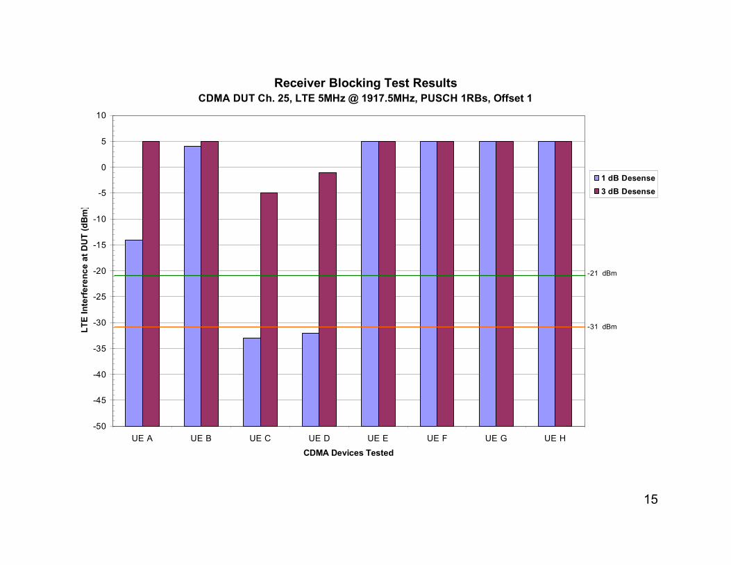
Receiver Blocking Test Results
-50
-45
-40
-35
-30
-25
-20
-15
-10
-5
0
5
10
UE A UE B UE C UE D UE E UE F UE G UE H
CDMA Devices Tested
LTE
Inte
rfere
nce a
t D
UT (dB
m)
1 dB Desense
3 dB Desense
CDMA DUT Ch. 25, LTE 5MHz @ 1917.5MHz, PUSCH 23RBs, Offset 1
-21 dBm
-31 dBm
15
Receiver Blocking Test Results
-50
-45
-40
-35
-30
-25
-20
-15
-10
-5
0
5
10
UE A UE B UE C UE D UE E UE F UE G UE H
CDMA Devices Tested
LTE
Inte
rfere
nce a
t D
UT (dB
m)
1 dB Desense
3 dB Desense
CDMA DUT Ch. 25, LTE 5MHz @ 1917.5MHz, PUSCH 1RBs, Offset 1
-21 dBm
-31 dBm

16
Receiver Blocking Test Results
-50
-45
-40
-35
-30
-25
-20
-15
-10
-5
0
5
10
UE A UE B UE C UE D UE E UE F UE G UE H
CDMA Devices Tested
LTE
Inte
rfere
nce a
t D
UT (dB
m)
1 dB Desense
3 dB Desense
CDMA DUT Ch. 25, LTE 5MHz @ 1917.5MHz, PUSCH 1RBs, Offset 13
-21 dBm
-31 dBm
17
Receiver Blocking Test Results
-50
-45
-40
-35
-30
-25
-20
-15
-10
-5
0
5
10
UE A UE B UE C UE D UE E UE F UE G UE H
CDMA Devices Tested
LTE
Inte
rfere
nce a
t D
UT (dB
m)
1 dB Desense
3 dB Desense
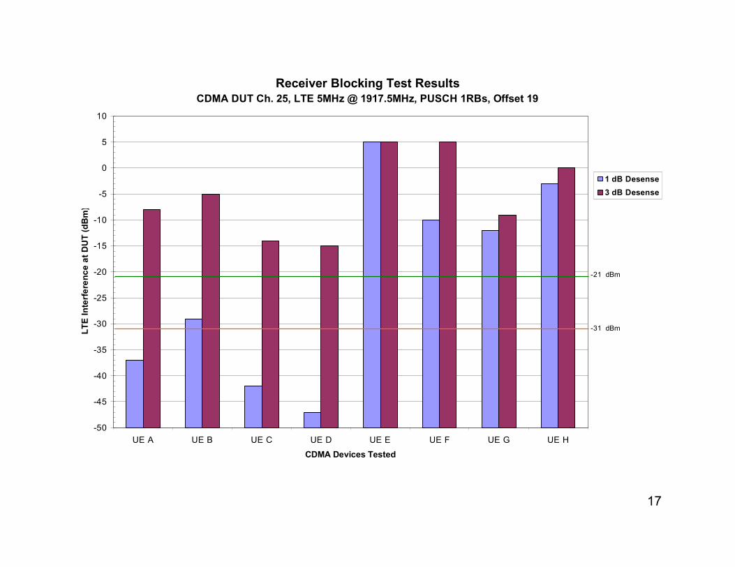
CDMA DUT Ch. 25, LTE 5MHz @ 1917.5MHz, PUSCH 1RBs, Offset 19
-21 dBm
-31 dBm

18
Receiver Blocking Test Results
-50
-45
-40
-35
-30
-25
-20
-15
-10
-5
0
5
10
UE A UE B UE C UE D UE E UE F UE G UE H
CDMA Devices Tested
LTE
Inte
rfere
nce a
t D
UT (dB
m)
1 dB Desense
3 dB Desense
CDMA DUT Ch. 25, LTE 5MHz @ 1917.5MHz, PUSCH 1RBs, Offset 23
-21 dBm
-31 dBm

19
Receiver Blocking Test Results
-50
-45
-40
-35
-30
-25
-20
-15
-10
-5
0
5
10
UE A UE B UE C UE D UE E UE F UE G UE H
CDMA Devices Tested
LTE
Inte
rfere
nce a
t D
UT (dB
m)
1 dB Desense
3 dB Desense
CDMA DUT Ch. 25, LTE 3MHz @ 1916.5MHz, PUCCH RB0/14
-21 dBm
-31 dBm

20
Receiver Blocking Test Results
-50
-45
-40
-35
-30
-25
-20
-15
-10
-5
0
5
10
UE A UE B UE C UE D UE E UE F UE G UE H
CDMA Devices Tested
LTE
Inte
rfere
nce a
t D
UT (dB
m)
1 dB Desense
3 dB Desense
CDMA DUT Ch. 25, LTE 3MHz @ 1916.5MHz, PUSCH 13RBs, Offset 1
-21 dBm
-31 dBm

21
Receiver Blocking Test Results
-50
-45
-40
-35
-30
-25
-20
-15
-10
-5
0
5
10
UE A UE B UE C UE D UE E UE F UE G UE H
CDMA Devices Tested
LTE
Inte
rfere
nce a
t D
UT (dB
m)
1 dB Desense
3 dB Desense
CDMA DUT Ch. 25, LTE 3MHz @ 1916.5MHz, PUSCH 4RBs, Offset 1
-21 dBm
-31 dBm

22
Receiver Blocking Test Results
-50
-45
-40
-35
-30
-25
-20
-15
-10
-5
0
5
10
UE A UE B UE C UE D UE E UE F UE G UE H
CDMA Devices Tested
LTE
Inte
rfere
nce a
t D
UT (dB
m)
1 dB Desense
3 dB Desense
CDMA DUT Ch. 25, LTE 3MHz @ 1916.5MHz, PUSCH 4RBs, Offset 10
-21 dBm
-31 dBm

23
Receiver Blocking Test Results
-50
-45
-40
-35
-30
-25
-20
-15
-10
-5
0
5
10
UE A UE B UE C UE D UE E UE F UE G UE H
CDMA Devices Tested
LTE
Inte
rfere
nce a
t D
UT (dB
m)
1 dB Desense
3 dB Desense
CDMA DUT Ch. 25, LTE 1.4MHz @ 1919MHz, PUCCH RB0/6
-21 dBm
-31 dBm

24
Receiver Blocking Test Results
-50
-45
-40
-35
-30
-25
-20
-15
-10
-5
0
5
10
UE A UE B UE C UE D UE E UE F UE G UE H
CDMA Devices Tested
LTE
Inte
rfere
nce a
t D
UT (dB
m)
1 dB Desense
3 dB Desense
CDMA DUT Ch. 25, LTE 1.4MHz @ 1919MHz, PUSCH 4RBs, Offset 1
-21 dBm
-31 dBm

25
Intermodulation and Receiver Blocking Test Results
-50
-45
-40
-35
-30
-25
-20
-15
-10
-5
0
5
10
UE A UE B UE C UE D UE E UE F UE G UE H
CDMA Devices Tested
LTE
Inte
rfere
nce a
t D
UT (dB
m)
1 dB Desense
3 dB Desense
CDMA DUT Ch. 575, LTE 5MHz @ 1917.5MHz, PUCCH RB0/24
-21 dBm
-31 dBm

26
Intermodulation and Receiver Blocking Test Results
-50
-45
-40
-35
-30
-25
-20
-15
-10
-5
0
5
10
UE A UE B UE C UE D UE E UE F UE G UE H
CDMA Devices Tested
LTE
Inte
rfere
nce a
t D
UT (dB
m)
1 dB Desense
3 dB Desense
CDMA DUT Ch. 550, LTE 5MHz @ 1917.5MHz, PUSCH 23RBs, Offset 1
-21 dBm
-31 dBm

27
Intermodulation and Receiver Blocking Test Results
-50
-45
-40
-35
-30
-25
-20
-15
-10
-5
0
5
10
UE A UE B UE C UE D UE E UE F UE G UE H
CDMA Devices Tested
LTE
Inte
rfere
nce a
t D
UT (dB
m)
1 dB Desense
3 dB Desense
CDMA DUT Ch. 525, LTE 5MHz @ 1917.5MHz, PUSCH 1RBs, Offset 1
-21 dBm
-31 dBm

28
Intermodulation and Receiver Blocking Test Results
-50
-45
-40
-35
-30
-25
-20
-15
-10
-5
0
5
10
UE A UE B UE C UE D UE E UE F UE G UE H
CDMA Devices Tested
LTE
Inte
rfere
nce a
t D
UT (dB
m)
1 dB Desense
3 dB Desense
CDMA DUT Ch. 550, LTE 5MHz @ 1917.5MHz, PUSCH 1RBs, Offset 13
-21 dBm
-31 dBm

29
Intermodulation and Receiver Blocking Test Results
-50
-45
-40
-35
-30
-25
-20
-15
-10
-5
0
5
10
UE A UE B UE C UE D UE E UE F UE G UE H
CDMA Devices Tested
LTE
Inte
rfere
nce a
t D
UT (dB
m)
1 dB Desense
3 dB Desense
CDMA DUT Ch. 575, LTE 5MHz @ 1917.5MHz, PUSCH 1RBs, Offset 19
-21 dBm
-31 dBm

30
Intermodulation and Receiver Blocking Test Results
-50
-45
-40
-35
-30
-25
-20
-15
-10
-5
0
5
10
UE A UE B UE C UE D UE E UE F UE G UE H
CDMA Devices Tested
LTE
Inte
rfere
nce a
t D
UT (dB
m)
1 dB Desense
3 dB Desense
CDMA DUT Ch. 575, LTE 5MHz @ 1917.5MHz, PUSCH 1RBs, Offset 23
-21 dBm
-31 dBm

31
Intermodulation and Receiver Blocking Test Results
-50
-45
-40
-35
-30
-25
-20
-15
-10
-5
0
5
10
UE A UE B UE C UE D UE E UE F UE G UE H
CDMA Devices Tested
LTE
Inte
rfere
nce a
t D
UT (dB
m)
1 dB Desense
3 dB Desense
CDMA DUT Ch. 550, LTE 3MHz @ 1916.5MHz, PUCCH RB0/14
-21 dBm
-31 dBm

32
Intermodulation and Receiver Blocking Test Results
-50
-45
-40
-35
-30
-25
-20
-15
-10
-5
0
5
10
UE A UE B UE C UE D UE E UE F UE G UE H
CDMA Devices Tested
LTE
Inte
rfere
nce a
t D
UT (dB
m)
1 dB Desense
3 dB Desense
CDMA DUT Ch. 525, LTE 3MHz @ 1916.5MHz, PUSCH 13RBs, Offset 1
-21 dBm
-31 dBm
33
Intermodulation and Receiver Blocking Test Results
-50
-45
-40
-35
-30
-25
-20
-15
-10
-5
0
5
10
UE A UE B UE C UE D UE E UE F UE G UE H
CDMA Devices Tested
LTE
Inte
rfere
nce a
t D
UT (dB
m)
1 dB Desense
3 dB Desense
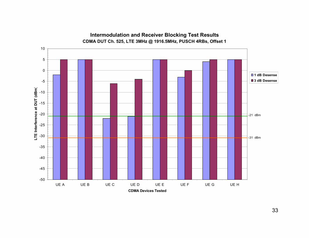
CDMA DUT Ch. 525, LTE 3MHz @ 1916.5MHz, PUSCH 4RBs, Offset 1
-21 dBm
-31 dBm
34
Intermodulation and Receiver Blocking Test Results
-50
-45
-40
-35
-30
-25
-20
-15
-10
-5
0
5
10
UE A UE B UE C UE D UE E UE F UE G UE H
CDMA Devices Tested
LTE
Inte
rfere
nce a
t D
UT (dB
m)
1 dB Desense
3 dB Desense
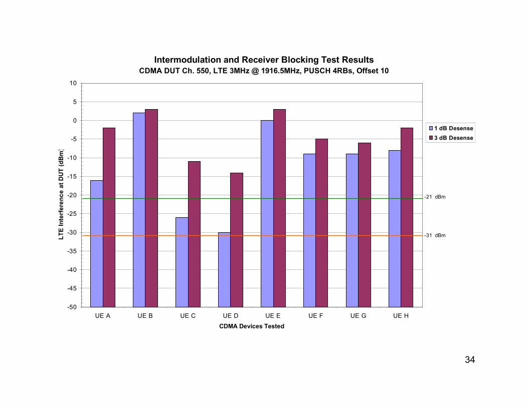
CDMA DUT Ch. 550, LTE 3MHz @ 1916.5MHz, PUSCH 4RBs, Offset 10
-21 dBm
-31 dBm

35
Intermodulation and Receiver Blocking Test Results
-50
-45
-40
-35
-30
-25
-20
-15
-10
-5
0
5
10
UE A UE B UE C UE D UE E UE F UE G UE H
CDMA Devices Tested
LTE
Inte
rfere
nce a
t D
UT (dB
m)
1 dB Desense
3 dB Desense
CDMA DUT Ch. 575, LTE 1.4MHz @ 1919MHz, PUCCH RB0/6
-21 dBm
-31 dBm
36
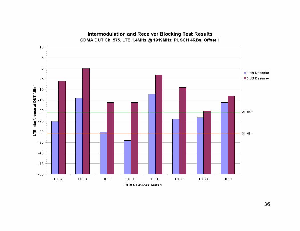
Intermodulation and Receiver Blocking Test Results
-50
-45
-40
-35
-30
-25
-20
-15
-10
-5
0
5
10
UE A UE B UE C UE D UE E UE F UE G UE H
CDMA Devices Tested
LTE
Inte
rfere
nce a
t D
UT (dB
m)
1 dB Desense
3 dB Desense
CDMA DUT Ch. 575, LTE 1.4MHz @ 1919MHz, PUSCH 4RBs, Offset 1
-21 dBm
-31 dBm

37
Receiver Blocking Test Results
-50
-45
-40
-35
-30
-25
-20
-15
-10
-5
0
5
10
1915 1916 1917 1918 1919 1920
LTE Interfering Signal, Frequency (MHz)
LTE
Inte
rfere
nce a
t D
UT (dB
m)
CDMA DUT Ch. 25, 1 dB Desense, UE A
38
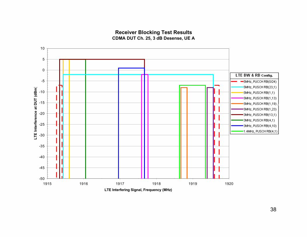
Receiver Blocking Test Results
-50
-45
-40
-35
-30
-25
-20
-15
-10
-5
0
5
10
1915 1916 1917 1918 1919 1920
LTE Interfering Signal, Frequency (MHz)
LTE
Inte
rfere
nce a
t D
UT (dB
m)
CDMA DUT Ch. 25, 3 dB Desense, UE A

39
Receiver Blocking Test Results
-50
-45
-40
-35
-30
-25
-20
-15
-10
-5
0
5
10
1915 1916 1917 1918 1919 1920
LTE Interfering Signal, Frequency (MHz)
LTE
Inte
rfere
nce a
t D
UT (dB
m)
CDMA DUT Ch. 25, 1 dB Desense, UE B

40
Receiver Blocking Test Results
-50
-45
-40
-35
-30
-25
-20
-15
-10
-5
0
5
10
1915 1916 1917 1918 1919 1920
LTE Interfering Signal, Frequency (MHz)
LTE
Inte
rfere
nce a
t D
UT (dB
m)
CDMA DUT Ch. 25, 3 dB Desense, UE B

41
Receiver Blocking Test Results
-50
-45
-40
-35
-30
-25
-20
-15
-10
-5
0
5
10
1915 1916 1917 1918 1919 1920
LTE Interfering Signal, Frequency (MHz)
LTE
Inte
rfere
nce a
t D
UT (dB
m)
CDMA DUT Ch. 25, 1 dB Desense, UE C

42
Receiver Blocking Test Results
-50
-45
-40
-35
-30
-25
-20
-15
-10
-5
0
5
10
1915 1916 1917 1918 1919 1920
LTE Interfering Signal, Frequency (MHz)
LTE
Inte
rfere
nce a
t D
UT (dB
m)
CDMA DUT Ch. 25, 3 dB Desense, UE C

43
Receiver Blocking Test Results
-50
-45
-40
-35
-30
-25
-20
-15
-10
-5
0
5
10
1915 1916 1917 1918 1919 1920
LTE Interfering Signal, Frequency (MHz)
LTE
Inte
rfere
nce a
t D
UT (dB
m)
CDMA DUT Ch. 25, 1 dB Desense, UE D
44
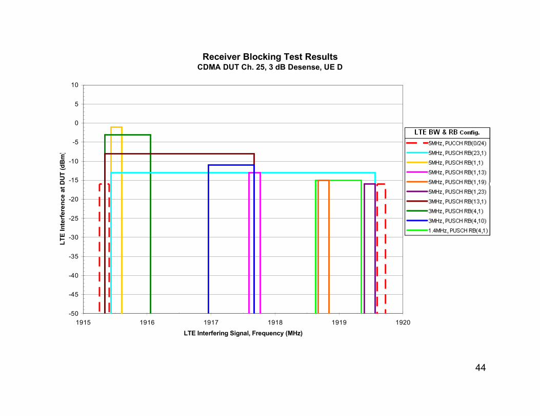
Receiver Blocking Test Results
-50
-45
-40
-35
-30
-25
-20
-15
-10
-5
0
5
10
1915 1916 1917 1918 1919 1920
LTE Interfering Signal, Frequency (MHz)
LTE
Inte
rfere
nce a
t D
UT (dB
m)
CDMA DUT Ch. 25, 3 dB Desense, UE D

45
Receiver Blocking Test Results
-50
-45
-40
-35
-30
-25
-20
-15
-10
-5
0
5
10
1915 1916 1917 1918 1919 1920
LTE Interfering Signal, Frequency (MHz)
LTE
Inte
rfere
nce a
t D
UT (dB
m)
CDMA DUT Ch. 25, 1 dB Desense, UE E

46
Receiver Blocking Test Results
-50
-45
-40
-35
-30
-25
-20
-15
-10
-5
0
5
10
1915 1916 1917 1918 1919 1920
LTE Interfering Signal, Frequency (MHz)
LTE
Inte
rfere
nce a
t D
UT (dB
m)
CDMA DUT Ch. 25, 3 dB Desense, UE E
47
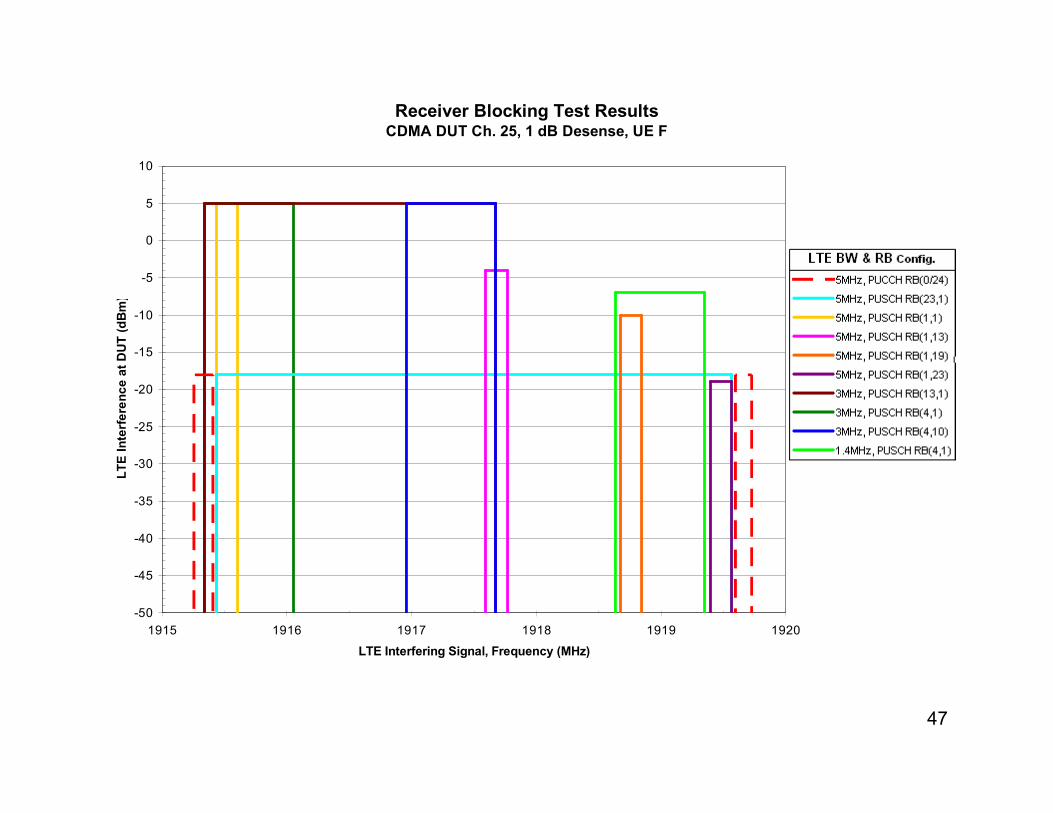
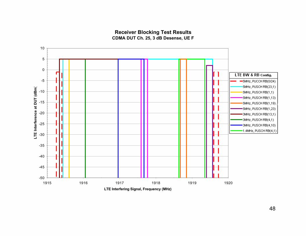
Receiver Blocking Test Results
-50
-45
-40
-35
-30
-25
-20
-15
-10
-5
0
5
10
1915 1916 1917 1918 1919 1920
LTE Interfering Signal, Frequency (MHz)
LTE
Inte
rfere
nce a
t D
UT (dB
m)
CDMA DUT Ch. 25, 1 dB Desense, UE F
48
Receiver Blocking Test Results
-50
-45
-40
-35
-30
-25
-20
-15
-10
-5
0
5
10
1915 1916 1917 1918 1919 1920
LTE Interfering Signal, Frequency (MHz)
LTE
Inte
rfere
nce a
t D
UT (dB
m)
CDMA DUT Ch. 25, 3 dB Desense, UE F

49
Receiver Blocking Test Results
-50
-45
-40
-35
-30
-25
-20
-15
-10
-5
0
5
10
1915 1916 1917 1918 1919 1920
LTE Interfering Signal, Frequency (MHz)
LTE
Inte
rfere
nce a
t D
UT (dB
m)
CDMA DUT Ch. 25, 1 dB Desense, UE G

50
Receiver Blocking Test Results
-50
-45
-40
-35
-30
-25
-20
-15
-10
-5
0
5
10
1915 1916 1917 1918 1919 1920
LTE Interfering Signal, Frequency (MHz)
LTE
Inte
rfere
nce a
t D
UT (dB
m)
CDMA DUT Ch. 25, 3 dB Desense, UE G

51
Receiver Blocking Test Results
-50
-45
-40
-35
-30
-25
-20
-15
-10
-5
0
5
10
1915 1916 1917 1918 1919 1920
LTE Interfering Signal, Frequency (MHz)
LTE
Inte
rfere
nce a
t D
UT (dB
m)
CDMA DUT Ch. 25, 1 dB Desense, UE H

52
Receiver Blocking Test Results
-50
-45
-40
-35
-30
-25
-20
-15
-10
-5
0
5
10
1915 1916 1917 1918 1919 1920
LTE Interfering Signal, Frequency (MHz)
LTE
Inte
rfere
nce a
t D
UT (dB
m)
CDMA DUT Ch. 25, 3 dB Desense, UE H

53
Intermodulation and Receiver Blocking Test Results
-50
-45
-40
-35
-30
-25
-20
-15
-10
-5
0
5
10
1915 1916 1917 1918 1919 1920
LTE Interfering Signal, Frequency (MHz)
LTE
Inte
rfere
nce a
t D
UT (dB
m)
CDMA DUT IM3 (Ch. 525, 550, or 575), 1 dB Desense, UE A

54
Intermodulation and Receiver Blocking Test Results
-50
-45
-40
-35
-30
-25
-20
-15
-10
-5
0
5
10
1915 1916 1917 1918 1919 1920
LTE Interfering Signal, Frequency (MHz)
LTE
Inte
rfere
nce a
t D
UT (dB
m)
CDMA DUT IM3 (Ch. 525, 550, or 575), 3 dB Desense, UE A

55
Intermodulation and Receiver Blocking Test Results
-50
-45
-40
-35
-30
-25
-20
-15
-10
-5
0
5
10
1915 1916 1917 1918 1919 1920
LTE Interfering Signal, Frequency (MHz)
LTE
Inte
rfere
nce a
t D
UT (dB
m)
CDMA DUT IM3 (Ch. 525, 550, or 575), 1 dB Desense, UE B

56
Intermodulation and Receiver Blocking Test Results
-50
-45
-40
-35
-30
-25
-20
-15
-10
-5
0
5
10
1915 1916 1917 1918 1919 1920
LTE Interfering Signal, Frequency (MHz)
LTE
Inte
rfere
nce a
t D
UT (dB
m)
CDMA DUT IM3 (Ch. 525, 550, or 575), 3 dB Desense, UE B

57
Intermodulation and Receiver Blocking Test Results
-50
-45
-40
-35
-30
-25
-20
-15
-10
-5
0
5
10
1915 1916 1917 1918 1919 1920
LTE Interfering Signal, Frequency (MHz)
LTE
Inte
rfere
nce a
t D
UT (dB
m)
CDMA DUT IM3 (Ch. 525, 550, or 575), 1 dB Desense, UE C

58
Intermodulation and Receiver Blocking Test Results
-50
-45
-40
-35
-30
-25
-20
-15
-10
-5
0
5
10
1915 1916 1917 1918 1919 1920
LTE Interfering Signal, Frequency (MHz)
LTE
Inte
rfere
nce a
t D
UT (dB
m)
CDMA DUT IM3 (Ch. 525, 550, or 575), 3 dB Desense, UE C

59
Intermodulation and Receiver Blocking Test Results
-50
-45
-40
-35
-30
-25
-20
-15
-10
-5
0
5
10
1915 1916 1917 1918 1919 1920
LTE Interfering Signal, Frequency (MHz)
LTE
Inte
rfere
nce a
t D
UT (dB
m)
CDMA DUT IM3 (Ch. 525, 550, or 575), 1 dB Desense, UE D

60
Intermodulation and Receiver Blocking Test Results
-50
-45
-40
-35
-30
-25
-20
-15
-10
-5
0
5
10
1915 1916 1917 1918 1919 1920
LTE Interfering Signal, Frequency (MHz)
LTE
Inte
rfere
nce a
t D
UT (dB
m)
CDMA DUT IM3 (Ch. 525, 550, or 575), 3 dB Desense, UE D

61
Intermodulation and Receiver Blocking Test Results
-50
-45
-40
-35
-30
-25
-20
-15
-10
-5
0
5
10
1915 1916 1917 1918 1919 1920
LTE Interfering Signal, Frequency (MHz)
LTE
Inte
rfere
nce a
t D
UT (dB
m)
CDMA DUT IM3 (Ch. 525, 550, or 575), 1 dB Desense, UE E

62
Intermodulation and Receiver Blocking Test Results
-50
-45
-40
-35
-30
-25
-20
-15
-10
-5
0
5
10
1915 1916 1917 1918 1919 1920
LTE Interfering Signal, Frequency (MHz)
LTE
Inte
rfere
nce a
t D
UT (dB
m)
CDMA DUT IM3 (Ch. 525, 550, or 575), 3 dB Desense, UE E

63
Intermodulation and Receiver Blocking Test Results
-50
-45
-40
-35
-30
-25
-20
-15
-10
-5
0
5
10
1915 1916 1917 1918 1919 1920
LTE Interfering Signal, Frequency (MHz)
LTE
Inte
rfere
nce a
t D
UT (dB
m)
CDMA DUT IM3 (Ch. 525, 550, or 575), 1 dB Desense, UE F

64
Intermodulation and Receiver Blocking Test Results
-50
-45
-40
-35
-30
-25
-20
-15
-10
-5
0
5
10
1915 1916 1917 1918 1919 1920
LTE Interfering Signal, Frequency (MHz)
LTE
Inte
rfere
nce a
t D
UT (dB
m)
CDMA DUT IM3 (Ch. 525, 550, or 575), 3 dB Desense, UE F

65
Intermodulation and Receiver Blocking Test Results
-50
-45
-40
-35
-30
-25
-20
-15
-10
-5
0
5
10
1915 1916 1917 1918 1919 1920
LTE Interfering Signal, Frequency (MHz)
LTE
Inte
rfere
nce a
t D
UT (dB
m)
CDMA DUT IM3 (Ch. 525, 550, or 575), 1 dB Desense, UE G
66
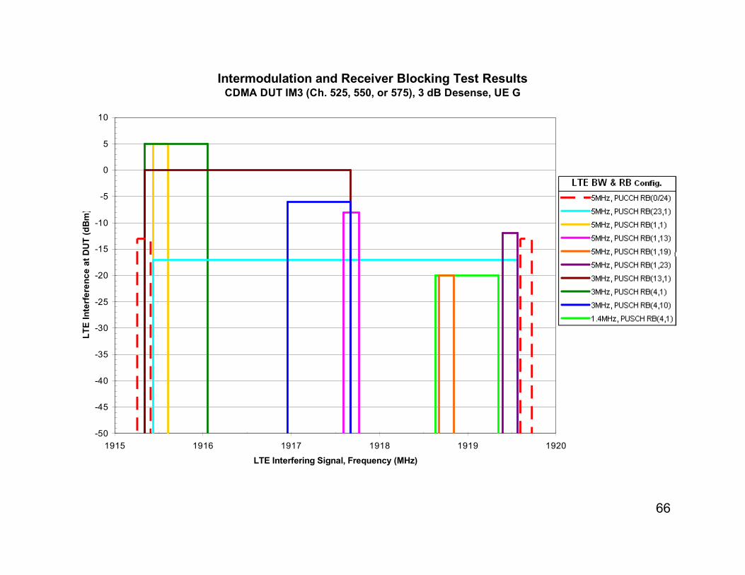
Intermodulation and Receiver Blocking Test Results
-50
-45
-40
-35
-30
-25
-20
-15
-10
-5
0
5
10
1915 1916 1917 1918 1919 1920
LTE Interfering Signal, Frequency (MHz)
LTE
Inte
rfere
nce a
t D
UT (dB
m)
CDMA DUT IM3 (Ch. 525, 550, or 575), 3 dB Desense, UE G

67
Intermodulation and Receiver Blocking Test Results
-50
-45
-40
-35
-30
-25
-20
-15
-10
-5
0
5
10
1915 1916 1917 1918 1919 1920
LTE Interfering Signal, Frequency (MHz)
LTE
Inte
rfere
nce a
t D
UT (dB
m)
CDMA DUT IM3 (Ch. 525, 550, or 575), 1 dB Desense, UE H

68
Intermodulation and Receiver Blocking Test Results
-50
-45
-40
-35
-30
-25
-20
-15
-10
-5
0
5
10
1915 1916 1917 1918 1919 1920
LTE Interfering Signal, Frequency (MHz)
LTE
Inte
rfere
nce a
t D
UT (dB
m)
CDMA DUT IM3 (Ch. 525, 550, or 575), 3 dB Desense, UE H

69
Co-Channel AWGN Test Results
-113
-107
-120
-118
-116
-114
-112
-110
-108
-106
-104
-102
-100
UE A UE B UE C UE D UE E UE F UE G UE H Average
CDMA Devices Tested
AW
GN
Inte
rfere
nce a
t D
UT (dB
m/M
Hz)
1 dB Desense
3 dB Desense
CDMA DUT Ch. 25, AWGN @ 1931.25MHz

70
Summary of Test Results
• Receiver Blocking test results with CDMA devices operating in PCS A Block at 1 dB desense interference thresholds occurred at:– H-Block interference levels at -33 to -47 dBm for UEs A, B, C, and D.
• This represents up to a 20 meter device separation for a H-Block LTE UE transmitting at full power for use case 1, and 6.3 meter separation for use case 2. Also, this represents a H-Block LTE UE transmitting as low as -3 dBm EIRP at 1 meter separation.
(Total UE coupling losses for use case 1 is 44 dB, and use case 2 is 54 dB.)
– H-Block interference levels at or above -19 dBm for UEs E, F, G and H.• This represents less than 1 meter device separation for a H-Block LTE UE transmitting at
full power +23 dBm. This represents a H-Block LTE UE transmitting at +25 dBm EIRP at 1 meter separation for these 4 devices.
– H-Block interference levels at an average of -21 dBm for the majority of devices (UEs A, B, E, F, G, H, excludes the worst case UEs C and D), which represents a H-Block LTE UE transmitting at full power 23 dBm at 1 meter device separation.
• Receiver Blocking test results with CDMA devices operating in PCS A Block at 3 dB desense interference thresholds occurred at:– H-Block interference levels above -21 dBm for all UEs, which represents less than
1 meter device separation for an H-Block LTE UE transmitting at full power.
• The worst case H-Block signal configuration in Receiver Blocking tests was LTE 5MHz at 1917.5MHz, 1 RB Offset 23 for all CDMA devices tested.– Some test cases showed similar interference levels to CDMA devices as this worst
case configuration, including tests with LTE 5MHz 1 RB offset 19, LTE 1.4MHz 4 RB offset 1, and LTE PUCCH test cases. Other test cases with RB allocations in lower offset configurations had slightly less interference to CDMA devices.

71
Summary of Test Results
• Intermodulation & Receiver Blocking test results with CDMA devices operating in PCS B Block at 1 dB desense interference thresholds occurred at:– H-Block interference levels at -25 to -35 dBm for UEs A, C and D.
• This represents up to a 5 meter device separation for a H-Block LTE UE transmitting at full power for use case 1, and 1.6 meter separation for use case 2. Also, this represents a H-Block LTE UE transmitting as low as +9 dBm EIRP at 1 meter separation for use case 1.
– H-Block interference levels above -21 dBm for UEs B, E, F, G, and H, which represents less than 1 meter device separation for a H-Block LTE UE transmitting at full power for these 5 devices.
• Intermodulation & Receiver Blocking test results with CDMA devices operating in PCS B Block at 3 dB desense interference thresholds occurred at:– H-Block interference levels above -21 dBm for all UEs, which represents less than
1 meter device separation for an H-Block LTE UE transmitting at full power.
• The worst case H-Block signal configuration in Intermodulation & Receiver Blocking tests was LTE 5MHz at 1917.5MHz with 1 RB at Offset 19 or 23 for all CDMA devices tested, depending on the device and test case for the corresponding 3rd order intermodulation product received in-band. Other test cases had similar or slightly less interference occurring to the CDMA devices under test.

72
Summary of Test Results
• Co-channel AWGN test results with CDMA devices at 1 dB desense interference thresholds occurred at:– AWGN interference levels at -113.5 to -111.5 dBm/MHz for all CDMA devices
tested with an average level of -113 dBm/MHz.
– For 1 meter device separation, this represents an H-Block out of band emissions (OOBE) of -69 and -59 dBm/MHz for device use cases 1 and 2, respectively.
• Co-channel AWGN test results with CDMA devices at 3 dB desense interference thresholds occurred at:– AWGN interference levels at -108 to -105.5 dBm/MHz for all CDMA devices tested
with an average level of -107 dBm/MHz.
– For 1 meter device separation, this represents an H-Block out of band emissions (OOBE) of -63 and -53 dBm/MHz for device use cases 1 and 2, respectively.

73
Supplemental Test Results
• 2 dB Desense Interference Testing
– Each device was additionally tested for Receiver Blocking and Intermodulation
interference at 2 dB desense thresholds.
– Tests use the worst case H-Block configuration of LTE 5MHz PUSCH 1 RB
offset 23 to determine the impact to PCS devices under test.

74
Receiver Blocking Test Results
-50
-45
-40
-35
-30
-25
-20
-15
-10
-5
0
5
10
UE A UE B UE C UE D UE E UE F UE G UE H
CDMA Devices Tested
LTE
Inte
rfere
nce a
t D
UT (dB
m)
1 dB Desense2 dB Desense3 dB Desense
CDMA DUT Ch. 25, LTE 5MHz @ 1917.5MHz, PUSCH 1RBs, Offset 23
-21 dBm
-31 dBm

75
Intermodulation and Receiver Blocking Test Results
-50
-45
-40
-35
-30
-25
-20
-15
-10
-5
0
5
10
UE A UE B UE C UE D UE E UE F UE G UE H
CDMA Devices Tested
LTE
Inte
rfere
nce a
t D
UT (dB
m)
1 dB Desense2 dB Desense3 dB Desense
CDMA DUT Ch. 575, LTE 5MHz @ 1917.5MHz, PUSCH 1RBs, Offset 23
-21 dBm
-31 dBm
76
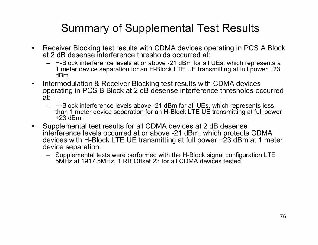
Summary of Supplemental Test Results
• Receiver Blocking test results with CDMA devices operating in PCS A Block at 2 dB desense interference thresholds occurred at:– H-Block interference levels at or above -21 dBm for all UEs, which represents a
1 meter device separation for an H-Block LTE UE transmitting at full power +23 dBm.
• Intermodulation & Receiver Blocking test results with CDMA devices operating in PCS B Block at 2 dB desense interference thresholds occurred at:– H-Block interference levels above -21 dBm for all UEs, which represents less
than 1 meter device separation for an H-Block LTE UE transmitting at full power +23 dBm.
• Supplemental test results for all CDMA devices at 2 dB desense interference levels occurred at or above -21 dBm, which protects CDMA devices with H-Block LTE UE transmitting at full power +23 dBm at 1 meter device separation.– Supplemental tests were performed with the H-Block signal configuration LTE
5MHz at 1917.5MHz, 1 RB Offset 23 for all CDMA devices tested.

77
Conclusions
• All of Verizon’s CDMA devices tested at 3 dB desense interference thresholds show Receiver Blocking and Intermodulation interference does not occur with H-Block LTE signals at 1 meter device separation.
• Half of Verizon CDMA devices tested (4 of 8 devices) at 1 dB desense interference thresholds show negligible Receiver Blocking or Intermodulation interference occurring from H-Block LTE signals at 1 meter device separation.
• Other Verizon CDMA devices tested (4 of 8 devices) at 1 dB desense interference thresholds show significant Receiver Blocking interference occurring from H-Block LTE signals at 1 meter device separation.
– For example, CDMA device UE C showed 1 dB desense interference occurring at -43 dBm for H-Block LTE interference case 1 RB offset 23. For use case 1 with 44 dB coupling loss between devices, to prevent interference to this CDMA device requires H-Block UE transmit power level of +1 dBm for 1 meter device separation, or H-Block UE transmit power at +23 dBm at 12.6 meter device separation. Also, CDMA device UE D showed 1 dB desense interference occurring in H-Block LTE tests at 1 RB offset 23 at -47 dBm, which is 4 dB more sensitive to H-Block interference as UE C.
– Some test cases showed similar interference to CDMA devices as the LTE 5MHz 1 RB offset 23 case, which include LTE 5MHz 1 RB offset 19, LTE 1.4MHz 4 RB offset 1, and LTE PUCCH test cases.

78
Conclusions
– CDMA devices UE A, B, C & D were 20 to 30 dB more sensitive to H-Block Receiver Blocking interference as compared to the other CDMA devices tested, and their 1 dB desense results were 22 to 31 dB more sensitive than 3 dB results.
• Due to the large disparity of Receiver Blocking results, further investigation of the receive path architecture for these devices is recommended to better understand the receiver rejection of H-Block, and to determine whether improvements in receiver rejection can be accomplished similar to other devices tested to limit 1 dB desense interference from H-Block to 1 meter device separations.
• In addition, testing with other PCS devices in the embedded base, including with UMTS and GSM devices, should be studied to determine their H-Block interference impacts.
• Supplemental tests were also performed at 2 dB desense interference threshold for Receiver Blocking and Intermodulation for the H-Block LTE 1 RB offset 23 case. – For this test case at the 2 dB desense interference threshold, all CDMA devices
show Receiver Blocking and Intermodulation interference does not occur with H-Block LTE signals at 1 meter device separation. Thus, for this case UE A through UE D is limited to 2 dB desense impact, while other devices tested limit this case to 1 dB desense impact.

79
Conclusions
• CDMA devices tested generally showed less sensitivity (better rejection) to Intermodulation interference as compared to Receiver Blocking – this is different from the 2004 devices tested when Intermodulation was the worst case. Thus, these Intermodulation results represent Intermodulation and Receiver Blocking occurring to CDMA devices operating in the PCS B-band.
• Based on Receiver Blocking test results, an H-Block mobile power limit of +23 dBm EIRP will prevent interference to the majority of PCS CDMA devices tested at 1 meter device separation.
– In addition, an implementation margin or tolerance of +/-2 dB can be considered for the mobile power limit, which is consistent with 3GPP LTE UE standards.
• In co-channel AWGN test results, Verizon’s CDMA devices show 1 dB desense interference occurring on average at -113 dBm/MHz, and 3 dB desense interference occurring on average at -107 dBm/MHz.
– For 1 meter device separation, this represents out of band emissions (OOBE) of -69 and -59 dBm/MHz for 1 dB desense interference for device use cases 1 and 2, respectively. Also, for 3 dB desense interference, this represents OOBE of -63 and -53 dBm/MHz, for device use cases 1 and 2, respectively.

80
Conclusions
• Based on test results with PCS CDMA devices, the H-Block mobile OOBE limit of -69 dBm/MHz is required to prevent desense interference greater than 1 dB for devices at 1 meter separation. – In addition, an implementation margin of 3 dB can be considered for an H-Block
OOBE limit of -66 dBm/MHz, which is consistent with OOBE limits proposed in the FCC NPRM in 2004 and 2008 of -66 dBm/MHz for the 1 meter user device separation case. This is also consistent with 3GPP OOBE limits for UMTS and HSPA devices, which is -60 dBm/3.84MHz or -66 dBm/MHz OOBE limits.
– This OOBE limit will prevent all devices tested from exceeding a 2 dB desense interference level (i.e. AWGN at -110 dBm/MHz with 44 dB UE coupling losses)
• In 2004 and 2008, CDMA operators advocated for an H-Block OOBE limit of -76 dBm/MHz RMS to protect CDMA devices, which is consistent withCDMA mobile standards. – The proposed RMS measurement provides 9 dB relief for GSM devices using 1
of 8 timeslots. GSM mobile standards OOBE limit of -71 dBm/100kHz (peak) is equivalent to -61 dBm/MHz (peak), or -70 dBm/MHz RMS.
– OOBE interference cannot be filtered at the victim device because its received as in-band noise, and thus must be mitigated at the source.
• OOBE of all devices tested in 2004 comply with -66 dBm/MHz, which includes CDMA, UMTS and GSM devices measured pursuant to CTIA’s H-Block tests.– CDMA and UMTS devices OOBE was -92 to -98 dBm/MHz, or an average of -95
dBm/MHz for CDMA devices and -97 dBm/MHz for UMTS device, which at least 26 dB below -66 dBm/MHz OOBE.

81
Conclusions
– GSM devices OOBE was -71 to -81 dBm/MHz, or an average of -78 dBm/MHz. GSM devices generally do not use transmit filters, which results in higher OOBE than CDMA & UMTS handsets, however devices meet -66 dBm/MHz with a 5 dB margin.
• 3GPP LTE device standards reference higher OOBE limits as compared to other technologies, which is -50 dBm/MHz. However, LTE device emissions are typically much lower because they utilize duplexers that provide 50 dB of rejection of receive bands to prevent self-desense interference. LTE standards do not indicate typical device operating margin for emissions below the limit.– LTE device emissions limits were relaxed by device vendors for bands with insufficient
separation and harmonics in UE co-existence bands such as for international roaming, however the same limit was applied for non-world devices that are not capable of international roaming and for bands without harmonics or spectrum separation issues.
– These limits were studied in device vendor's probability analyses with optimistic assumptions and higher interference levels, including higher user body losses and device noise figures may not represent typical data devices and uses, higher cell densities that overcome interference rather that lower site densities in smaller and rural markets, and analyses not accounting for in-building uses at lower signal levels that are more sensitive to interference and common network practices of site collocation resulting in higher correlation of receiving low signals while transmitting at high levels in the same locations.
– OOBE transmissions at -50 dBm/MHz can cause significant interference to nearby devices. For example, this is equivalent to receiving an in-band noise level of -94 dBm/MHz at 1 meter that can desense nearby devices by 13 dB, or causes 1 dB desense over 9 meters (254 sq. meter area), which significantly impacts the forward link budget that carries the majority of traffic of the system. (Example uses KTB -114 dBm/MHz, device use case 1, typ. device noise figure of 7 dB, device noise floor of -107 dBm/MHz)

82
Conclusions
• Agilent (Avago) the leading manufacturer of PCS device duplexers confirmed that H-Block devices can meet an OOBE limit of -76 dBm/MHz.– Agilent submitted this in its 2004 and 2005 filings in the FCC H-Block docket.
– This is for a split band duplexer, which is expected because a 70 MHz pass band with 10 MHz duplex gap is not feasible at 1.9 GHz.
– 10 MHz separation to the PCS mobile receive spectrum 1930-1995 MHz is sufficient to achieve this OOBE.
– This represents a 10 dB margin below the OOBE limit of -66 dBm/MHz. This is for current duplexer designs, which would not increase costs for H-Block devices.
• Therefore, the H-Block mobile OOBE limit of -66 dBm/MHz RMS is required to protect existing PCS devices from H-Block OOBE interference, and is reasonable and achievable with current duplexer designs.
• Based on test results, the H-Block Power limit of +23 dBm EIRP and OOBE limit of -66 dBm/MHz will protect the majority of devices tested to 1 dB interference levels and all devices tested to 2 dB interference levels at 1 meter device separation.

83
APPENDIX
84
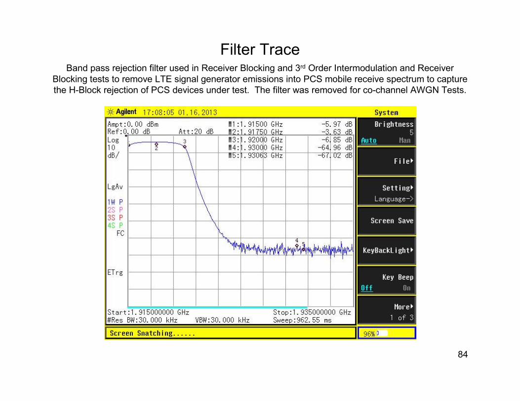
Filter TraceBand pass rejection filter used in Receiver Blocking and 3rd Order Intermodulation and Receiver
Blocking tests to remove LTE signal generator emissions into PCS mobile receive spectrum to capture
the H-Block rejection of PCS devices under test. The filter was removed for co-channel AWGN Tests.

85
V-COMM is a leading provider of wireless engineering consulting services to the
wireless telecommunications industry with offices in Cranbury, NJ and Exton, PA. V-
COMM’s engineering staff is experienced in Cellular, Personal Communications Services
(PCS), Advanced Wireless Services, 2G, 3G and 4G Wireless Broadband Data Services,
Microwave Radio, Broadcast TV engineering. We have provided our expertise to wireless
operators in engineering, system design, implementation, performance, optimization,
evaluation of new wireless technologies, and spectrum interference assessments.
We have extensive experience in analyzing interference in various spectrum bands
including Cellular, SMR, PCS, AWS, Air-to-ground, Public Safety, and 700 MHz spectrum.
We have engineering experience in all commercial wireless technologies, including LTE,
HSPA, UMTS, EVDO, CDMA, GSM, WiMAX, DVB-H, and Public Safety wireless
technologies including analog and digital Project 25, EDACS, Opensky, and other trunking
and conventional radio networks. V-COMM has studied interference and spectrum issues
for many spectrum licensees for numerous FCC proceedings, and V-COMM was selected by
the FCC & Department of Justice to provide expert analysis and testimony in the Nextwave
and Pocket Communications Bankruptcy cases.
For additional information, visit V-COMM’s web site at www.vcomm-eng.com.