t2 tibial nailing system - stryker meded · 4 the t2 tibial nailing system represents stryker’s...
TRANSCRIPT

T2 Tibial Nailing System
Operative Technique

2
Contributing Surgeons
Prof. Dr. med. Volker BührenChief of Surgical ServicesMedical Director of Murnau Trauma CenterMurnau, Germany
Kyle F. Dickson, MD, MBAProfessor and ChairmanUniversity of Texas Medical School at HoustonDepartment of Orthopaedic SurgeryHouston, TexasUSA
Paul Tornetta, III, M. D.Director of Orthopaedic Trauma, Boston Medical CenterProfessor and Vice Chairman Department of Orthopaedic SurgeryBoston University School of MedicineBoston, MassachusettsUSA
This publication sets forth detailed recommended procedures for using Stryker Osteosynthesis devices and instruments.
It offers guidance that you should heed, but, as with any such technical guide, each surgeon must consider the particular needs of each patient and make appropriate adjustments when and as required.
A workshop training is required prior to first surgery.
All non-sterile devices must be cleaned and sterilized before use. Follow the instructions provided in our reprocessing guide (L24002000). Multi-component instruments must be disassembled for cleaning. Please refer to the corresponding assembly/disassembly instructions.
See package insert (L22000007) for a complete list of potential adverse effects, contraindications, warnings and precautions. The surgeon must discuss all relevant risks, including the finite lifetime of the device, with the patient, when necessary.
Warning: All bone screws referenced in this document here are not approved for screw attachment or fixation to the posterior elements (pedicles) of the cervical, thoracic or lumbar spine.
T2 Tibial Nailing System

3
Contents
Page
1. Introduction 4
Implant Features 4
Technical Details 5
Instrument Features 6
References 6
2. Indications , Precautions & Contraindications 7
Indications 7
Precautions 7
Relative Contraindications 7
3. Pre-operative Planning 8
4. Operative Technique 9
Patient Positioning Options and Reduction 9
Incision 9
Entry Point 10
Unreamed Technique 11
Reamed Technique 11
Nail Selection 13
Nail Insertion 14
Guided Locking Mode (via Target Device) 17
Static Locking Mode 18
Freehand Distal Locking 21
End Cap Insertion 22
Dynamic Locking Mode 23
Apposition /Compression Locking Mode 24
Advanced Locking Mode 25
Nail Removal 26
8mm End Cap & Blocking Screw Technique 27
Blocking Screw Technique (optional) 28
Ordering Information – Implants 29
Ordering Information – Instruments 33

4
The T2 Tibial Nailing System represents Stryker’s latest and most comprehensive development of the original intramedullary principles presented by Prof. Gerhard Küntscher in 1940.Stryker has created a next generation locking nail system, bringing together all the capabilities and benefits of sepa rate nailing systems to create a single, integrated surgical resource for fixa tion of long bone fractures.
The T2 Tibial Nailing System is the realization of superior biome-chanical intramedullary stabilization using small caliber, strong can nu lated implants for internal fixation of long bones.
According to the fracture type, the system offers the option of dif fer ent locking modes. In addition to static locking, a controlled dynami zation with rotational stability is optional.
In some indications, a controlled apposition/compression of bone fragments can be applied by introducing a Compression Screw from the top of the nail. To further increase rotational stability, the nail can be locked statically after using the controlled dynamization and apposition/compression option.The Compression Screw is pushed against the proximal Partially Threaded Locking Screw that has been placed in the oblong hole, drawing the distal segment towards the fracture site. In stable fractures, this has the biomechanical advantage of creating active circumferential compression to the fracture site, transferring axial load to the bone, and reducing the function of the nail as a load bearing device (1).
This ability to transfer load back to the bone can reduce the incidence of implant failure secondary to fatigue. Typical statically locked nails function
Implant Features
Introduction
* The Distal Tibia Nail is not cleared for primary ankle arthrodesis in the U.S.
The T2 Tibial Nailing System offers the competitive advantages of:
• Not limiting the approach to a certain nailing technique.• Accommodating reamed or unreamed procedures.• Providing locking options for all types of fractures, plus the Advanced Locking Mode for increased rotational stability.
Through the development of a com-mon, streamlined and intuitive surgi cal approach, both in principle and in detail, the T2 Tibial Nail ing System offers significantly increased speed and functionality for the treat -ment of fractures as well as sim-plifying the training require ments for all personnel involved.
as load bearing devices and failure rates in excess of 20 % have been reported (2).
The beneficial effect of apposition/compression in treating long bone fractures in cases involving trans verse and short oblique fractures that are axially stable is well documented (3, 4).In addition to the T2 Stand ard Tibial Nail that features options to address very proximal and very distal fractures as well as the ad vanced compression feature, there are two additional Tibial Nail design available on a special order basis that address specific surgical indications:
The T2 Distal Tibial Nail, avail able in 10mm diameter only, may be used for very distal fractures*. As with the Standard Nail, an oblong hole is located in the proximal third of the nail for optional controlled dynamization and apposition/com pression. Compared to the Stand-ard Nail, the oblong hole is 7mm further distal, ending just above the Herzog 10 ° bend. The Distal Tibial Nail has 2 distal locking holes at 5mm and 13mm centered from the distal tip.
The T2 Proximal Tibial Nail may also be used for very proximal and very distal fractures. The Proximal Tibial Nail does not feature an oblong hole for optional controlled dynamization and apposition/compression.
The location of the 3 distal locking holes is the same as the Standard Nail.
Note:All three nail designs feature the distal most hole centered at 5mm from the distal tip to better address hard to reach distal fractures.
Common 5mm cortical screws simplify the surgical procedure and promote a minimally invasive approach. Fully Threaded Locking Screws are available for regular locking procedures. Partially Thread-ed Locking Screws (Shaft Screws) are designed for use if apposition/ com pres sion is applied.
Caution:The 8mm T2 Tibial Nail can only be locked distally with 4mm Fully Threaded screws. As with all diameters of T2 Tibial Nails, the proximal screws are 5mm.
One common Compression Screw to close the fracture site, and End Caps in eight sizes are available to provide an improved fit for every indication.
All implants in the T2 Tibial Nailing System are gun-drilled and made of Type II anodized titanium alloy (Ti6AL4V) for enhanced bio me-chanical and biomedical per formance.

5
NailsDiameters 8*–15mmSizes 240–420mm
10 ° A / P slope
Compression Range**34
41
Herzog Bend, 10 °(All Three Nails)
1350mm
+ Distal
0mm
1724 4148
50.5
CompressionRange**
0mm
1724
50.0
2515
0mm
5
25
15
50mm
Distal Bend, 4 °(All Three Nails)
60mm
0mm
1724
31.5
43.550.0
SLOT
+ ProximalStandard
Introduction
Technical Details
5.0mm Fully ThreadedLocking ScrewsL = 25–120mm
4.0mm Fully ThreadedLocking Screws for 8mm Nails (Distal Holes Only)L = 20–60mm
5.0mm Partially Threaded Locking Screws(Shaft Screws)L = 25–120mm
Tibia AdvancedCompression Screw
* 8mm nails require 4mm Fully Threaded Screws for Distal Locking+ Proximal and Distal Nails are available as special
order implants
Note:Screw Length is measured from top of head to tip.
End Caps
Standard +5mm +10mm +15mm
** Compression Range Total Length of Slot 12mm Less Screw Diameter (-) 5mm
Maximum Movement of Screw 7mm
+20mm +25mm +30mm +35mm
Fully Threaded
6
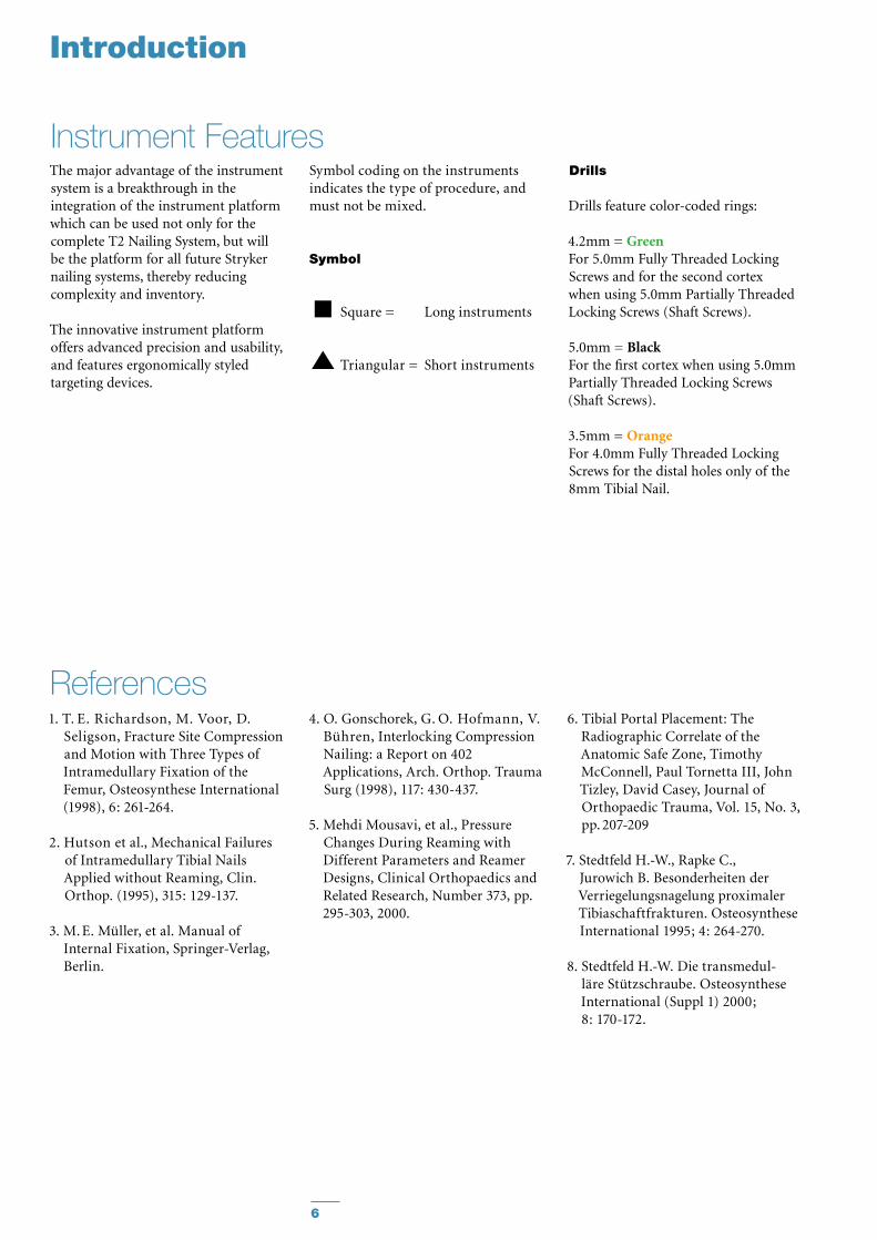
The major advantage of the instrument system is a breakthrough in the integration of the instrument platform which can be used not only for the complete T2 Nailing System, but will be the platform for all future Stryker nailing systems, thereby reducing complexity and inventory.
The innovative instrument platform offers advanced precision and usability, and features ergonomically styled targeting devices.
Instrument Features
Introduction
References1. T. E. Richardson, M. Voor, D.
Seligson, Fracture Site Compression and Motion with Three Types of Intramedullary Fixation of the Femur, Osteosynthese International (1998), 6: 261-264.
2. Hutson et al., Mechanical Failures of Intramedullary Tibial Nails Applied without Reaming, Clin. Orthop. (1995), 315: 129-137.
3. M. E. Müller, et al. Manual of Internal Fixation, Springer-Verlag, Berlin.
4. O. Gonschorek, G. O. Hofmann, V. Bühren, Interlocking Compression Nailing: a Report on 402 Applications, Arch. Orthop. Trauma Surg (1998), 117: 430-437.
5. Mehdi Mousavi, et al., Pressure Changes During Reaming with Different Parameters and Reamer Designs, Clinical Orthopaedics and Related Research, Number 373, pp. 295-303, 2000.
6. Tibial Portal Placement: The Radiographic Correlate of the Anatomic Safe Zone, Timothy McConnell, Paul Tornetta III, John Tizley, David Casey, Journal of Orthopaedic Trauma, Vol. 15, No. 3, pp. 207-209
7. Stedtfeld H.-W., Rapke C., Jurowich B. Besonder heiten der Verriegelungsnagelung proximaler Tibiaschaftfrakturen. Osteosynthese International 1995; 4: 264-270.
8. Stedtfeld H.-W. Die transmedul-läre Stützschraube. Osteosynthese International (Suppl 1) 2000; 8: 170-172.
Drills
Drills feature color-coded rings:
4.2mm = GreenFor 5.0mm Fully Threaded Locking Screws and for the second cortex when using 5.0mm Partially Threaded Locking Screws (Shaft Screws).
5.0mm = BlackFor the first cortex when using 5.0mm Partially Threaded Locking Screws (Shaft Screws).
3.5mm = OrangeFor 4.0mm Fully Threaded Locking Screws for the distal holes only of the 8mm Tibial Nail.
Symbol coding on the instruments indicates the type of procedure, and must not be mixed.
Symbol
Square = Long instruments
Triangular = Short instruments
7
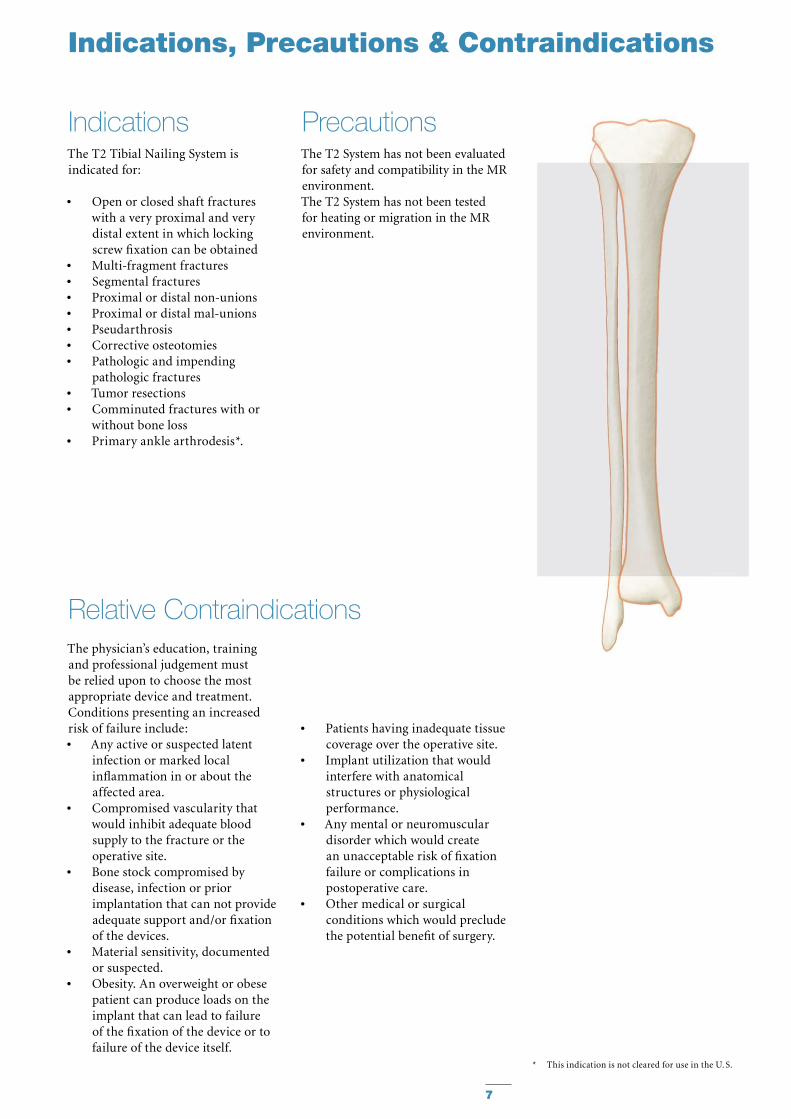
The T2 Tibial Nailing System is indicated for:
Open or closed shaft fractures •with a very proximal and very distal extent in which locking screw fixation can be obtainedMulti-fragment fractures•Segmental fractures•Proximal or distal non-unions•Proximal or distal mal-unions•Pseudarthrosis•Corrective osteotomies•Pathologic and impending •pathologic fracturesTumor resections•Comminuted fractures with or •without bone lossPrimary ankle arthrodesis *.•
The T2 System has not been evaluatedfor safety and compatibility in the MRenvironment.The T2 System has not been testedfor heating or migration in the MRenvironment.
Indications Precautions
Relative Contraindications
Indications, Precautions & Contraindications
The physician’s education, training and professional judgement must be relied upon to choose the most appropriate device and treatment. Conditions presenting an increased risk of failure include:
Any active or suspected latent •infection or marked local inflammation in or about the affected area.Compromised vascularity that •would inhibit adequate blood supply to the fracture or the operative site.Bone stock compromised by •disease, infection or prior implantation that can not provide adequate support and/or fixation of the devices.Material sensitivity, documented •or suspected.Obesity. An overweight or obese •patient can produce loads on the implant that can lead to failure of the fixation of the device or to failure of the device itself.
* This indication is not cleared for use in the U. S.
Patients having inadequate tissue •coverage over the operative site.Implant utilization that would •interfere with anatomical structures or physiological performance.Any mental or neuromuscular •disorder which would create an unacceptable risk of fixation failure or complications in postoperative care.Other medical or surgical •conditions which would preclude the potential benefit of surgery.

8
Pre-Operative Planning
An X-Ray Template (1806-0000 for Standard and Proximal nails, 1806-0001 for Distal nails) is available for pre-operative planning.
Thorough evaluation of preoperative radiographs of the affected extremity is critical. Careful radiographic examination can prevent intra-operative complications.
For standard mid-shaft fractures, the proper nail length should extend from just below the Tibial Plateau at the appropriate medio-lateral position to just proximal to the Epiphyseal Scar of the ankle joint.
This allows the surgeon to consider the apposition/compression feature of the T2 Standard Tibial Nail and T2 Distal Tibial Nail knowing that 7mm of active apposition/compression is possible, prior to determining the final length of the implant. If ap po-sition/compression is planned, the nail should be at least 7mm shorter.
Note:Check with local representative regarding availability of sizes and nail types.

9
Fig. 1
a) The patient is placed in the supine position on a radiolucent fracture table and the leg is hyperflexed on the table with the aid of a leg holder,
or
b) The leg is free draped and hung over the edge of the table (Fig. 1).
The knee is flexed to >90°. A triangle may be used under the knee to accommodate flexion intra-operatively. It is important that the knee rest is placed under the posterior aspect of the lower thigh in order to reduce the risk of vascular compression and of pushing the proximal fragment of the tibia anteriorly.Anatomical reduction can be achieved by internal or external rotation of the fracture and by traction, adduction or abduction, and must be confirmed under image intensification. Draping must leave the knee and the distal end of the leg exposed.
IncisionBased on radiological image, a para-tendenous incision is made from the patella extending down approximately 1.5–4cm in preparation of nail insertion. The Patellar Tendon may be retracted laterally or split at the junction of the medial third, and lateral two-thirds of the Patellar Ligament. This determines the entry point (Fig. 2).
Patient Positioning Options and Reduction
Operative Technique
Fig. 2

10
Fig. 3
Fig. 5Fig. 4
Operative Technique
L M
The medullary canal is opened through a superolateral plateau entry portal. The center point of the portal is located slightly medial to the lateral tibial spine as visualized on the A/P radiograph and immediately adjacent and anterior to the anterior articular margin as visualized on the true la-teral radiograph. It is located lateral to the midline of the tibia by an average of 6 percent of the tibial plateau width. Radiographic confirmation of this area is essential to prevent damage to the intra-articular structure during portal placement and nail insertion (Fig. 3).
The opening should be directed with a central orientation in relation to the medullary canal. After penetra-ting the cortex with the 3×285mm K-Wire (1806-0050S), the Ø12mm Rigid Reamer (1806-2014) is used to access the medullary canal (Fig. 4). Alternatively, to penetrate the cortex, the Ø10mm Straight (1806-0045), “spe-cial order” Ø11.5mm Straight (1806-0047), or Curved (1806-0040) Awl may be used (Fig. 5).
Caution:A more distal entry point may •result in damage to the posterior cortex during nail insertion.Guiding the Rigid Reamer over •the K-Wire prior to K-Wire inser-tion within the Proximal Tibia will help to keep it straight while guiding the opening instrument centrally towards the canal. Do not use bent K-Wires.
Note:During opening the entry portal with the Awl, dense cortex may block the tip of the Awl. An Awl Plug (1806-0032) can be inserted through the Awl to avoid penetra-tion of bone debris into the can-nulation of the Awl shaft.
Entry Point

11
Fig. 8
For reamed techniques, the 3×800mm Ball Tip Guide Wire (1806-0080S) is inserted through the fracture site. Except for the 8mm Tibial Nails, use of the Ball Tip Guide Wire does not require a Guide Wire exchange. The Universal Rod with Reduction Spoon may be used as a fracture reduction tool to facilitate Guide Wire insertion through the fracture site (see Fig. 7).
Note:The Ball Tip at the end of the Guide Wire will stop the reamer head.
Reaming (Fig. 8) is commenced in 0.5mm increments until cortical contact is appreciated. Final reaming should be 1mm –1.5mm larger than the diameter of the nail to be used
If an unreamed technique is preferred, the 3×800mm Smooth Tip Guide Wire (1806-0090S) is passed through the fracture site using the Guide Wire Handle (1806-1095 and 1806-1096) (Fig. 6). The Universal Rod (1806-0110) with Reduction Spoon (1806-0125) may be used as a fracture reduction tool to facilitate Guide Wire insertion (Fig. 7), and as a “sound” to help determine the diameter of the medullary canal. The Universal Rod is 9mm diameter. Internal rotation during insertion will aid in passing the Guide Wire down the tibial shaft. The Guide Wire should lie in the center of the metaphysis and the diaphysis in both the A/P and Lateral views to avoid offset positioning of the nail. The Guide Wire handle is removed leaving the Guide Wire in place.
Unreamed Technique
Reamed Technique
Fig. 6
Fig. 7
Operative Technique

12
Fig. 9
Fig. 10
Operative Technique
The Guide Wire Pusher can be used to help keep the Guide Wire in position during reamer shaft extraction. The metal cavity at the end of the handle pushed on the end of the power tool facilitates to hold the Guide Wire in place when starting to pull the power tool (Fig. 9). When close to the Guide Wire end place the Guide Wire Pusher with its funnel tip to the end of the power tool cannulation (Fig. 10). While removing the power tool the Guide Wire Pusher will keep the Guide Wire in place.
Caution: The proximal diameter of the 8mm –11mm diameter nails is 11.5mm. Additional metaphyseal reaming may be required to facilitate nail insertion. Nail sizes 12–15mm have a constant diameter.
Note:8mm Tibial Nails cannot be •inserted over the 3×800mm Ball Tip Guide Wire (1806-0080S). The Ball Tip Guide wire must be exchanged for the 3×800mm Smooth Tip Guide Wire (1806-0090S) prior to nail insertion. Use the Teflon Tube (1806-0073S) •for the Guide Wire exchange.

13
End of Guide Wire Ruleris the measurement reference
Hole Positions
Fig. 11
Compression Slot1. Dynamic2. Static -> Standard Nail Only 3. Dynamic -> Distal Nail Only
Oblique Holes-Static
Proximal Distal
Length
Hole Positions
DiameterThe diameter of the selected nail should be 1–1.5mm smaller than that of the last reamer used.
LengthThe X-Ray Ruler (1806-0010) may be used to determine nail diameter and length. The X-Ray Ruler may also be used as a guide to help determine final Locking Screw positions (Fig. 11).
Note:X-Ray Ruler also features Distal Hole Configurations
Alternatively, nail length may be deter-mined by measuring the remaining length of the Guide Wire. The Guide Wire Ruler (1806-0022) is placed on the Guide Wire and the correct nail length is read at the end of the Guide Wire on the Guide Wire Ruler (Fig. 12).
Caution:If the fracture is suitable for appo-sition/compression, the implant selected should be 7–12mm shorter than measured to help avoid migration of the nail beyond the insertion site. The Guide Wire Ruler is calibrated for 800mm and 1000mm Guide Wires with markings for the Tibia, Femur and Humerus.
Upon completion of reaming, the appropriate size nail is ready for insertion.
Nail Selection
Operative Technique
Fig. 12
The Guide Wire Ruler can be easily folded and unfolded.

14
Caution: Prior to insertion:
1. Recheck that the Nail is tightly secured to the Nail Handle.
2. Verify the hole pattern and appro-priate locking options for the Nail type selected. This is extremely important since the proximal hole patterns are different among the Proximal, Standard and Distal Nails.
3. Check correct alignment by inserting a drill bit through the assembled Tissue Protection and Drill Sleeve placed in the required holes of the targeting device.
4. T2 Tibial nails with diameters 9mm–15mm do not require a Guide Wire exchange.
Operative Technique
Strike Plate
Nail Holding Screw
Nail Handle
Targeting Arm
Fig. 13
Nail InsertionThe selected nail is assembled onto the Tibial Target Device (1806-1000) with the Tibial Nail Holding Screw (1806-0370) (Fig. 13). Securely tighten the Nail Holding Screw with the Insertion Wrench (1806-0135) so that it does not loosen during nail insertion.
To attach the Nail Handle to the Targeting Arm, turn the Quick-Lock Ring on the Targeting Arm clockwise. Triangles on the Quick-Lock Ring and the Targeting Arm indicate the cor-rect position to attach the Nail Handle when both triangles are in line with each other.

15
Fig. 15
Fig. 16
Fig. 14
If a Guide Wire is used, it is important to note that only the 8mm Tibial Nails require exchanging the 3×800mm Ball Tip Guide Wire (1806-0080S) for the 3×800mm Smooth-Tip Guide Wire (1806-0090S) prior to insertion. Use the Teflon Tube (1806-0073S) to facili-tate the Guide Wire exchange.
The Strike Plate (1806-0150) is threaded into the Nail Handle next to the Nail Holding Screw.
The Nail is inserted by hand over the 3×800mm Ball Tip Guide Wire (if used) and into the entry site of the proximal tibia (Fig. 14). Gently manipulate the nail to help avoid penetration of the posterior cortex. If the nail is deflected towards the posterior cortex, remove the nail, and hyperflex the knee. Under image con-trol, use a straight reamer to ream an anterior tract in the proximal frag-ment.
The Nail is advanced through the entry point past the fracture site to the appropriate level. Remove the Guide Wire once the nail is past the fracture site.
The Slotted Hammer can be used on the Strike Plate (Fig. 15) or if dense bone is encountered, alternatively, the Universal Rod may be attached to the Strike Plate and used in conjunction with the Slotted Hammer (1806-0170) to insert the nail (Fig. 16).
Operative Technique

16
Fig. 17 Fig. 18
12mm compression slot allows 7mm of compression (Standard and Distal Nails Only)
Fig. 18a
12mm
7mm
2mm
Apposition/Compression
Static
Dynamic
Fig. 19
Turn silver Quick- Lock Ring Clockwise
Bring Targeting Arm up to Nail Handle
The three circumferential grooves on the insertion post act as a guide while inserting the nail to the correct depth. When locking the Tibial Nail in the Static Mode, the nail is countersunk a minimum of 2mm to the chondral surface (Fig. 17). When the implant is inserted in the Dynamic Mode, with active apposition/compression or in the Advanced Locking Mode, the recommended insertion depth is 7mm or 12mm based on how much active compression is to be applied (Fig. 18). The final nail depth should be well below the chondral surface to minimize irritation to the Patellar Tendon.
If the nail has been inserted to far, it has to be repositioned. Repositioning of the nail should be carried out either by hand or by using the Strike Plate attached to the Target Device. The Universal Rod and Slotted Hammer may then be attached to the Strike Plate to carefully and smoothly retract the assembly. DO NOT hit on the Target Device.
Attach the Targeting Arm to the Nail Handle by rotating the spring loaded Quick-Lock Ring on the Target Arm clockwise while connecting it to the knob on the end of the Nail Handle (Fig. 19).
Note:Remove the Guide Wire prior to drilling holes and inserting the Locking Screws.
A chamfer is located on the proximal end of the nail to help identify the junction of the nail and insertion post under fluoroscopy. Three circumferential grooves are located on the insertion post of the Target Device Assembly at 2mm, 7mm and 12mm from the proximal end of the nail. Depth of insertion may be visualized with the aid of fluoroscopy.
Caution:Compression Slot on the Distal Nail is located 7mm further Distal than on the Standard Nail.
Operative Technique

17
(via Target Device)
Before locking the nail proximally, recheck that the Nail Holding Screw is securely tightened by using the Insertion Wrench, and check that the Target Arm is properly attached to the Nail Handle. The Target Device is designed to provide four options for proximal locking when using the Standard Tibial Nail (Fig. 19.1–19.3).
In Static Locking Mode all three indicated holes may be used (Fig. 19.1).
1. Static2. Static3. Static
The dynamic hole is used to lock the nail in the controlled Dynamization or Apposition/Compression Modes (Fig. 19.2).
4. Dynamic
Guided Locking ModeBoth the dynamic and more proximal of the two oblique locking holes are used in the Advanced Locking Mode. Proper placement of the Advanced Compression Screw against the transverse Partially Threaded Locking Screw (Shaft Screw) will block the more distal of the two oblique locking holes even if fully compressed (Fig. 19.3).
4. Dynamic1. Static
Caution:Any attempt to drill across the more distal of the two oblique locking holes may result in particulate debris generation or a broken drill.
The Long Tissue Protection Sleeve (1806-0185) together with the Long Drill Sleeve (1806-0215) and the Long Trocar (1806-0315) is inserted into the Target Device by pressing the safety clip (Fig. 20). The mechanism will keep the sleeve in place and prevent it from falling out. It will also prevent
the sleeve from sliding during screw measurement. To release the Tissue Protection Sleeve, the safety clip must be pressed again and held while removing the sleeve.
Caution:The Proximal Tibial Nail does •not feature a proximal oblong Dynamic/Compression hole. If a Proximal Tibial Nail is implanted, do not attempt to drill through the dynamic and static M/L holes on the Target Device. Only use the number 1 and number 2 static holes (Fig. 19.1).The location of the oblong hole •on the Distal Tibial Nail is 7mm more distal than the hole location for the Standard Tibial Nail. If a Distal Tibial Nail is implanted, do not attempt to drill through the Dynamic M/L hole on the Target Device or you will hit the nail. Only use the static hole numbered 1, 2, and 3. (Fig. 19.1)
Fig. 19.2 Fig. 20There are four safety clips
Caution: For Standard and Distal Nail only.
4
Fig. 19.1 Fig. 19.3
3
2 1
4
1
released locked
Operative Technique

18
Fig. 21
Fig. 22
For static locking of the Standard Tibial Nail, both proximal oblique screws and the M/L Locking Screw may be used. In highly unstable, com-minuted fractures the M/L screw is placed in the static position of the oblong hole. This may further improve stability of the proximal frag-ment.
If secondary dynamization is planned, the M/L screw may be inserted in the dynamic position of the oblong hole on the Target Device. This allows con-trolled dynamization of the fracture in cases of delayed union after removal of the proximal oblique screws.
Caution: If secondary dynamiztion is used with the Distal Tibial Nail, the M/L screw has to be inserted through the distal most part of the oblong hole the Target Device. (The oblong hole on the Distal Tibial Nail is 7mm more distal than on the Standard Tibial Nail).
Always start with the most distal oblique Fully Threaded Locking Screw. The Long Tissue Protection Sleeve (assembled with the Long Drill Sleeve and Trocar) is positoned through the static locking hole on the Target Device. A small skin incision is made, and while pressing the safety clip, the Tissue Protection Sleeve is pushed through until it is in contact with the anterior cortex (Fig. 21).
Caution: Make sure the Tissue Protection Sleeve/Drill Sleeve Assembly is seated on bone prior to selecting final screw length.
The Long Trocar is removed, with the Tissue Protection Sleeve and Drill Sleeve remaining in position.
Static Locking Mode
Operative Technique

19
Fig. 23
50mm
Operative Technique
For accurate drilling and easy deter- mination of screw length, use the center-tipped, calibrated Ø4.2×340mm Drill (1806-4260S). The centered Drill is forwarded through the Drill Sleeve and pushed onto the cortex.After drilling both cortices, the screw length may be read directly off of the calibrated Drill at the end of the Drill Sleeve. If measurement with the Screw Gauge, Long is preferred, first remove the Drill Sleeve, Long and read the screw length directly at the end of the Tissue Protection Sleeve, Long (Fig. 22 and Fig. 23).
The position of the end of the Drill as it relates to the far cortex is equal to where the end of the screw will be. Therefore, if the end of the Drill is 3mm beyond the far cortex, the end of the screw will also be 3mm beyond.
The Screw Gauge, Long, is calibrated so that with the bend at the end pulled back flush with the far cortex, the screw tip will end 3mm beyond the far cortex (Fig. 23).
Alternatively, stop the drill when it engages the far cortex and measure the drill bit depth off of the calibrated drill. Add 5mm to this length to obtain the correct screw length.
When the Drill Sleeve is removed, the correct Locking Screw is inserted through the Tissue Protection Sleeve using the Long Screwdriver Shaft AO (1806-0227) with the Teardrop Handle (702429).

20
Caution: The coupling of Elastosil handles contains a mechanism with one or multiple ball bearings. In case of applied axial stress on the Elastosil handle, those compo-nents are pressed into the sur-rounding cylinder resulting in a complete blockage of the device and possible bending.To avoid intra-operative com-plications and secure long-term functionality, we mandate that Elastosil handles be used only for their intended use. DO NOT HIT hit on them.
Alternatively, the 3.5mm Hex Self-Holding Screwdriver Extra Short(1806-0203) or Long (1806-0233)can be used for the screw insertion.
The screw is advanced through both cortices. The screw is near its’ proper seating position when the groove around the shaft of the screwdriver is approaching the end of the Tissue Protection Sleeve (Fig. 24).
Repeat the locking procedure for the more proximal oblique Locking Screw (Fig. 25 and Fig. 26).
Fig. 24
Fig. 25
Fig. 26
Operative Technique

21
Fig. 27
Fig. 28
Fig. 29
Fig. 30
The freehand technique is used to insert Locking Screws into both the M/L and A/P holes in the nail. Rotational alignment must be checked prior to locking the nail statically.
Multiple locking techniques and radiolucent drill devices are available for freehand locking. The critical step with any freehand locking technique is to visualize a perfectly round locking hole with the C-Arm.
The center-tipped Ø4.2×130mm Drill (1806-4280S) is held at an oblique angle pointing to the center of the locking hole (Fig. 27 and Fig. 28). Upon X-Ray verification, the Drill is placed perpendicular to the nail and drilled through the medial cortex. Confirm in both the A/P and M/L planes by X-Ray that the drill passes through the hole in the nail.
The Screw Gauge, Long (1806-0331) can be used to determine the screw length (Fig. 29).
As detailed in the proximal locking section (Fig. 23, p. 19), the position of the end of the drill is equal to the end of the screw as they relate to the far cortex.
Routine Locking Screw insertion is employed (Fig. 30) with the assembled Screwdriver Shaft and Teardrop Handle.Alternatively, the 3.5mm Hex Self-Holding Screwdriver Extra-short(1806-0203) can be used for thescrew insertion.
Note: A fully threaded End Cap is available to lock down on the most proximal screw and create a fixed angle construct.
Caution:Distal locking should always •be performed with two screws, locking the hole nearest the fracture site first. On the Standard and Proximal Tibial nails, always lock the most
Freehand Distal Locking
Operative Technique
proximal M/L hole. The most distal hole of all three nail types is M/L. The next most proximal hole on all three nails is A/P. The Standard and Proximal Nails have a third more proximal M/L hole.8mm Tibial Nails must always be •locked distally with 4mm Fully Threaded Screws.
For the 8mm Tibial Nails, the Ø3.5×130mm Drill (1806-3550S) is used to drill both cortices prior to inserting the 4mm Fully Threaded Locking Screws in the distal holes. With all sizes of T2 Tibial Nails, the 8mm Nails use 5.0 mm Screws proximally.

22
Fully Threaded
Fig. 32
Fig. 33
Standard +5mm +10mm +15mm +20mm +25mm +30mm +35mm
Fig. 31
After removal of the Target Device, an End Cap is used. Eight different sizes of End Caps* are available to adjust nail length and to reduce the potential for bony ingrowth into the proximal threads of the nail (Fig. 31).
The End Cap is inserted with the Screwdriver Shaft and Teardrop Handle after intra-operative radio-graphs show satisfactory reduction and hardware implantation (Fig. 32 and 33). Fully seat the End Cap to minimize the potential for loosening.
Thoroughly irrigate the wound to prevent debris from remaining within the knee joint. Close the wound using standard technique.
* Optional 8mm diameter End Caps are available in +5, +10 and +15mm length to facilitate insertion through the Nail Adapter (see page 27).
End Cap Insertion
Operative Technique

23
When the fracture profile permits, dynamic locking may be utilized for transverse, axially stable fractures. Controlled dynamization is performed by statically locking the nail distally with at least two screws in a freehand technique.
Note:The Proximal and Standard Nails each have one A/P and two M/L distal screw hole options. The Distal Nail has one M/L (the most distal) and one A/P distal screw hole.
In the Dynamic Locking Mode of the Standard Tibial Nail, the Partially Threaded Locking Screw (Shaft Screw) is placed in the dynamic position of the M/L oblong hole (Fig. 34). The two oblique proximal screws are not inserted. This allows the nail to move relative to the Partially Threaded Locking Screw (Shaft Screw) and the fracture to settle while maintaining torsional stability.For screw insertion, follow the procedure described above (see Fig. 35 and 36).
Caution:When using the Distal Tibial Nail, •the M/L screw has to be inserted in the static position of the oblong hole on the Targeting Device. It is important to note that the position of the oblong hole of this nail is 7mm more distal than on the Standard Nail.When using the Distal Tibial Nail, •static locking of the proximal M/L oblong hole can only be performed freehand.Dynamic locking is not intended •for and not possible with the Proximal Tibial Nail. There is no oblong hole in the nail. The proximal end of the nail must •be buried at least 7mm–12mm into the bone to reduce the potential for impingement or irritation of the Patellar Tendon if the nail migrates during dynamization.
Dynamic Locking Mode
Fig. 36
Fig. 35
Fig. 34
Operative Technique

24
In transverse or axially stable fracture patterns, active apposition/compres-sion increases fracture stability, may enhance fracture healing and allow for early weight bearing. The T2 Standard Tibial Nail and T2 Distal Tibial Nail provide the option to treat a tibial fracture with active mechanical appo-sition/compression prior to leaving the operating room.
Caution:Distal freehand static locking with at least two screws must be performed prior to applying active, controlled apposition/compression to the fracture site.
If active apposition/compression is required for the T2 Standard Tibial Nail, a Partially Threaded Locking Screw is inserted via the Target Device in the dynamic position of the of the oblong hole. The Distal Tibial Nail uses the static position of the oblong hole.
This will allow for a maximum of 7mm of active, controlled apposi-tion/compression using the Advanced Compression Screw. In order to insert the Partially Threaded Locking Screw (Shaft Screw), drill both cortices with the Ø4.2×340mm Drill (1806-4260S). Correct screw length may be read from the calibration on the Drill at the end of the Drill Sleeve. The near cor-tex ONLY is overdrilled using the Ø5×230mm Drill (1806-5000S).
Note: It may be easier to insert the Compres sion Screw prior to fully seating the nail. Once the nail tip has cleared the fracture site, the guide wire (if used) is withdrawn. With the proximal portion of the nail still not fully seated and extending out of the bone, the Nail Holding Screw is removed and the Compression Screw is inserted. Care should be taken that the shaft of the Compression Screw does not extend into the area of the oblong hole.
Apposition/ Compression Locking ModeAnother alternative is that after the Partially Threaded Locking Screw (Shaft Screw) is inserted, the Nail Holding Screw securing the nail to the insertion post is removed, leaving the insertion post intact with the nail (Fig. 37). This will act as a guide for the Compression Screw (Fig. 38).
The Compression Screw is inserted with the Compression Screwdriver Shaft (1806-0268) assembled on the Teardrop Handle through the inser-tion post. When the ring marked with a “T” on the Compression Screwdriver Shaft is close to the Target Device, it indicates the engagement of the appo-sition/compression feature of the nail.
Note:The ring marked with an “F” is for the Femoral Compression Screw.
The Long Tissue Protection Sleeve is removed and the Compression Screw is gently tightened utilizing the two-finger technique. As the Compression Screw is advanced against the 5.0mm Partially Threaded Locking Screw (Shaft Screw), it draws the distal frac-ture segment towards the fracture site, employing active apposition/compres-sion (Fig. 39). Image intensification will enable the surgeon to visua l ize active apposition/compres sion. Some bending of the Partially Threaded Locking Screw may be seen.
Caution:Prior to compressing the fracture, •the nail must be countersunk a safe distance from the entry point to accommodate for the 7mm of active compression. The three grooves on the insertion post help attain accurate insertion depth of the implant.Apposition/compression should •be carried out under fluoros-copy. Overtightening of the Compression Screw onto the Partially Threaded Locking Screw (Shaft Screw) may result in the screw to fail.
Fig. 39
Fig. 38
Fig. 37
Operative Technique

25
In order to achieve additional fixa-tion, and to reduce the load on the Partially Threaded Locking Screw, the design of the T2 Standard Tibial Nail and T2 Distal Tibial Nail provide the opportunity to insert an additional Fully Threaded Locking Screw (Shaft Screw) into the more proximal of the two oblique holes after the optimum amount of apposition/compression is attained.
Affix the Compression Screw onto the self-retaining Compression Screw-driver Shaft. Remove the Nail Holding Screw leaving the Target Device in place. Advance the Compression Screw through the Target Device until the ring marked with a “ T ” on the Compres sion Screwdriver Shaft is close to the Target Device and com-pression is applied (Fig. 40).To insert the Advanced Compression Screw, follow the procedure on page 24.
Note:As previously described, it may be easier to insert the Compression Screw prior to fully seating the nail.
To reattach the Target Device, detach the Teardrop Handle from the Compression Screwdriver Shaft and screw the Nail Holding Screw over the Compression Screwdriver Shaft back into position (Fig. 41).Prior to guided locking via the Target Device, the Nail Holding Screw must be securely tightened with the Insertion Wrench.
Caution: When using the Advanced Compres sion Screw, only the more proximal oblique hole can be locked with a screw. The more distal oblique hole will be partially blocked by the top of the Advanced Compression Screw regardless of the amount of compression applied to the Shaft Screw in the M/L oblong hole.
To insert the proximal oblique Fully Threaded Locking Screw (Fig. 42), fol-low the locking procedure for static locking (see Fig. 32 and 33 and on page 22).
Advanced Locking Mode
Fig. 42
Fig. 40
Fig. 41
Operative Technique

26
Nail removal is an elective procedure.
If needed, the End Cap and Advanced Compression Screw are removed with the Screwdriver Shaft and Tear drop Handle. If the Advanced Locking Mode was utilized, first remove the End Cap, then the most proximal screw, then the Advanced Compression Screw can be removed (Fig. 43).
Note:As an alternative to removing the Advanced Compression Screw (if used), it can be just disengaged from the Partially Threaded Locking Screw (Shaft Screw) by turning the Compression Screwdriver one full turn in a counter-clockwise direction. There is no need to remove it from the nail.
Caution:DO NOT remove the last proxi-mal Locking Screw prior to attaching the Universal Rod to the proximal end of the nail. Doing so may result in the nail moving posteriorly, making it dif-ficult to attach the Universal Rod to the nail.
The Universal Rod is inserted into the driving end of the nail. All Locking Screws are removed with the Long Screwdriver Shaft and Teardrop Handle (Fig. 44).
Alternatively, the 3.5mm Hex Self-Holding Screwdriver Long (1806-0233) or Extra Short (1806-0203) can be used for the screw removal.
The Slotted Hammer or optional Sliding Hammer is used to extract the nail in a controlled manner (Fig. 45).
Note:Stryker offers also a special Extraction Set for the removal of internal fixation systems and associated screws. For more information, please refer to the Literature Number B1000057.
Close the wound in the usual manner.
Nail Removal
Fig. 43
Fig. 44
Fig. 45
Operative Technique

27
Features and Benefits
Fig. 47 Fig. 48
Mechanics of Blocking Screw
Superolateral Entry Portal / Radiographic location of Superolateral Nail Entry Portal
Fig. 49b
Blocking Screw
Awl
Nail
Blocking Screw
Just medial to lateral spine Anterior adjacent to joint
Insertion of an 8mm End Cap (optional)
Fig. 46a Fig. 46b Fig. 46c
Fig. 49a
8mm End Cap & Blocking Screw Technique

28
The nail often sits against the posteri-or cortex which causes anterior angu-lation of the fracture because the shaft position is fixed by the nail (Fig. 50). The principle of the use of a Blocking
For Varus/ Valgus AdjustmentOne of the advantages of the very proximal bend in the nail, is its’ use-fulness in correcting varus/valgus angulation. Do not lock the nail dis-tally until after angular correction.
Features and Benefits
Screw is to prevent posterior nail passage by decreasing the effective diameter of the canal and directing the nail more anterior as shown (Fig. 51). Using the superolateral entry
point and with the Blocking Screw in place, the nail accurately aligns the shaft (fracture) (Fig. 52) (6, 7, 8)
Fig. 51
Blocking Screw
Placed to PreventNail passage
Fig. 52
Fig. 53a Fig. 53b Fig. 53c
Blocking Screw
Cross Locking Screws
Blocking Screw
10° Herzog Bend
Place the Blocking Screw at the level of the Proximal (Herzog) Bend (Fig. 53a). In cases where a Blocking Screw is used, simple rotation of the nail (Fig. 53b) will allow the Herzog Bend to correct the angulation (Fig. 53c).
Note:As an option, or in an exchange/revision nailing with a more distal entry portal, this principal can also be applied with a Lateral Blocking Screw placed a/P as an alternative method to help pre-vent Varus/Valgus deformity.
Fig. 50
Blocking Screw Technique (optional)
29
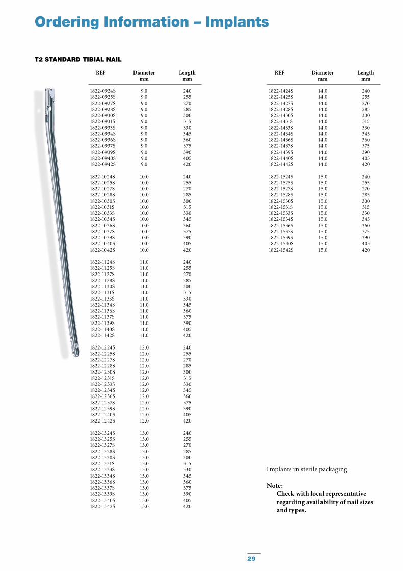
REF Diameter Length mm mm
1822-0924S 9.0 240 1822-0925S 9.0 255 1822-0927S 9.0 270 1822-0928S 9.0 285 1822-0930S 9.0 300 1822-0931S 9.0 315 1822-0933S 9.0 330 1822-0934S 9.0 345 1822-0936S 9.0 360 1822-0937S 9.0 375 1822-0939S 9.0 390 1822-0940S 9.0 405 1822-0942S 9.0 420
1822-1024S 10.0 240 1822-1025S 10.0 255 1822-1027S 10.0 270 1822-1028S 10.0 285 1822-1030S 10.0 300 1822-1031S 10.0 315 1822-1033S 10.0 330 1822-1034S 10.0 345 1822-1036S 10.0 360 1822-1037S 10.0 375 1822-1039S 10.0 390 1822-1040S 10.0 405 1822-1042S 10.0 420
1822-1124S 11.0 240 1822-1125S 11.0 255 1822-1127S 11.0 270 1822-1128S 11.0 285 1822-1130S 11.0 300 1822-1131S 11.0 315 1822-1133S 11.0 330 1822-1134S 11.0 345 1822-1136S 11.0 360 1822-1137S 11.0 375 1822-1139S 11.0 390 1822-1140S 11.0 405 1822-1142S 11.0 420
1822-1224S 12.0 240 1822-1225S 12.0 255 1822-1227S 12.0 270 1822-1228S 12.0 285 1822-1230S 12.0 300 1822-1231S 12.0 315 1822-1233S 12.0 330 1822-1234S 12.0 345 1822-1236S 12.0 360 1822-1237S 12.0 375 1822-1239S 12.0 390 1822-1240S 12.0 405 1822-1242S 12.0 420
1822-1324S 13.0 240 1822-1325S 13.0 255 1822-1327S 13.0 270 1822-1328S 13.0 285 1822-1330S 13.0 300 1822-1331S 13.0 315 1822-1333S 13.0 330 1822-1334S 13.0 345 1822-1336S 13.0 360 1822-1337S 13.0 375 1822-1339S 13.0 390 1822-1340S 13.0 405 1822-1342S 13.0 420
T2 STANDARD TIBIAL NAIL
REF Diameter Length mm mm
1822-1424S 14.0 240 1822-1425S 14.0 255 1822-1427S 14.0 270 1822-1428S 14.0 285 1822-1430S 14.0 300 1822-1431S 14.0 315 1822-1433S 14.0 330 1822-1434S 14.0 345 1822-1436S 14.0 360 1822-1437S 14.0 375 1822-1439S 14.0 390 1822-1440S 14.0 405 1822-1442S 14.0 420
1822-1524S 15.0 240 1822-1525S 15.0 255 1822-1527S 15.0 270 1822-1528S 15.0 285 1822-1530S 15.0 300 1822-1531S 15.0 315 1822-1533S 15.0 330 1822-1534S 15.0 345 1822-1536S 15.0 360 1822-1537S 15.0 375 1822-1539S 15.0 390 1822-1540S 15.0 405 1822-1542S 15.0 420
Implants in sterile packaging
Note:Check with local representative regarding availability of nail sizes and types.
Ordering Information – Implants

30
Implants in sterile packaging
Proximal Tibial Nails available as Special Order.
Note:Check with local representative regarding availability of nail sizes and types.
REF Diameter Length mm mm
1823-0924S 9.0 240 1823-0925S 9.0 255 1823-0927S 9.0 270 1823-0928S 9.0 285 1823-0930S 9.0 300 1823-0931S 9.0 315 1823-0933S 9.0 330 1823-0934S 9.0 345 1823-0936S 9.0 360 1823-0937S 9.0 375 1823-0939S 9.0 390 1823-0940S 9.0 405 1823-0942S 9.0 420
1823-1024S 10.0 240 1823-1025S 10.0 255 1823-1027S 10.0 270 1823-1028S 10.0 285 1823-1030S 10.0 300 1823-1031S 10.0 315 1823-1033S 10.0 330 1823-1034S 10.0 345 1823-1036S 10.0 360 1823-1037S 10.0 375 1823-1039S 10.0 390 1823-1040S 10.0 405 1823-1042S 10.0 420
1823-1124S 11.0 240 1823-1125S 11.0 255 1823-1127S 11.0 270 1823-1128S 11.0 285 1823-1130S 11.0 300 1823-1131S 11.0 315 1823-1133S 11.0 330 1823-1134S 11.0 345 1823-1136S 11.0 360 1823-1137S 11.0 375 1823-1139S 11.0 390 1823-1140S 11.0 405 1823-1142S 11.0 420
1823-1224S 12.0 240 1823-1225S 12.0 255 1823-1227S 12.0 270 1823-1228S 12.0 285 1823-1230S 12.0 300 1823-1231S 12.0 315 1823-1233S 12.0 330 1823-1234S 12.0 345 1823-1236S 12.0 360 1823-1237S 12.0 375 1823-1239S 12.0 390 1823-1240S 12.0 405 1823-1242S 12.0 420
1823-1324S 13.0 2401823-1325S 13.0 255 1823-1327S 13.0 270 1823-1328S 13.0 285 1823-1330S 13.0 300 1823-1331S 13.0 315 1823-1333S 13.0 330 1823-1334S 13.0 345 1823-1336S 13.0 360 1823-1337S 13.0 375 1823-1339S 13.0 390 1823-1340S 13.0 405 1823-1342S 13.0 420
T2 PROxIMAL TIBIAL NAIL
REF Diameter Length mm mm
1823-1424S 14.0 240 1823-1425S 14.0 255 1823-1427S 14.0 270 1823-1428S 14.0 285 1823-1430S 14.0 300 1823-1431S 14.0 315 1823-1433S 14.0 330 1823-1434S 14.0 345 1823-1436S 14.0 360 1823-1437S 14.0 375 1823-1439S 14.0 390 1823-1440S 14.0 405 1823-1442S 14.0 420
1823-1524S 15.0 240 1823-1525S 15.0 255 1823-1527S 15.0 270 1823-1528S 15.0 285 1823-1530S 15.0 300 1823-1531S 15.0 315 1823-1533S 15.0 330 1823-1534S 15.0 345 1823-1536S 15.0 360 1823-1537S 15.0 375 1823-1539S 15.0 390 1823-1540S 15.0 405 1823-1542S 15.0 420
Ordering Information – Implants

31
REF Diameter Length mm mm
1896-4020S 4.0 201896-4025S 4.0 251896-4030S 4.0 301896-4035S 4.0 351896-4040S 4.0 401896-4045S 4.0 451896-4050S 4.0 501896-4055S 4.0 551896-4060S 4.0 60
4MM FuLLy THREADED LOCKINg SCREwS
1891-5025S1891-5030S1891-5035S1891-5040S1891-5045S1891-5050S1891-5055S1891-5060S1891-5065S1891-5070S1891-5075S1891-5080S1891-5085S1891-5090S1891-5095S1891-5100S1891-5105S1891-5110S1891-5115S1891-5120S
5MM PARTIALLy THREADED LOCKINg SCREwS+
5.0 255.0 305.0 355.0 405.0 455.0 505.0 555.0 605.0 655.0 705.0 755.0 805.0 855.0 905.0 955.0 1005.0 1055.0 1105.0 1155.0 120
REF Diameter Length mm mm
1896-5025S1896-5027S1896-5030S1896-5032S1896-5035S1896-5037S1896-5040S1896-5042S1896-5045S1896-5047S1896-5050S1896-5052S1896-5055S1896-5057S1896-5060S1896-5065S1896-5070S1896-5075S1896-5080S1896-5085S1896-5090S1896-5095S1896-5100S1896-5105S1896-5110S1896-5115S1896-5120S
5.0 25.05.0 27.55.0 30.05.0 32.55.0 35.0 5.0 37.55.0 40.0 5.0 42.55.0 45.0 5.0 47.5 5.0 50.05.0 52.5 5.0 55.0 5.0 57.5 5.0 60.0 5.0 65.0 5.0 70.0 5.0 75.0 5.0 80.0 5.0 85.0 5.0 90.0 5.0 95.0 5.0 100.05.0 105.05.0 110.05.0 115.05.0 120.0
REF Diameter Length mm mm
1824-1024S 10.0 2401824-1025S 10.0 2551824-1027S 10.0 2701824-1028S 10.0 2851824-1030S 10.0 3001824-1031S 10.0 3151824-1033S 10.0 3301824-1034S 10.0 3451824-1036S 10.0 3601824-1037S 10.0 3751824-1039S 10.0 3901824-1040S 10.0 4051824-1042S 10.0 420
T2 DISTAL TIBIAL NAIL 5MM FuLLy THREADED LOCKINg SCREwS+
Ordering Information – Implants
REF Diameter Length mm mm
Proximal and Distal Tibial Nails avail-able as Special Order
+ Outside of the U. S., Locking Screws may be ordered non-sterile without the “S” at the end of the corresponding Catalogue Number.
SHAFT SCREwS

32
Implants in sterile packaging
Note: Check with local representative regarding availability of nail sizes and types.
Partially Threaded Locking Screws (Shaft Screws) are used in conjunction with the Advanced Compression Screw feature of the Distal and Standard Nails, or may also be used as a “Blocking Screw“ with all three nail types, including the Proximal Nail.(See optional “Blocking Screw Technique“ section on pages 27 and 28)
Ordering Information – Implants
REF Diameter mm
1822-0001S 8.0+5mm
+10mm +15mm
StandardFully Threaded
REF Diameter Length mm mm
1827-0004S 7.0 Fully Threaded1822-0003S 8.0 Standard1822-0005S 11.5 + 5mm1822-0010S 11.5 +10mm1822-0015S 11.5 +15mm1822-0020S 11.5 +20mm1822-0025S 11.5 +25mm1822-0030S 11.5 +30mm1822-0035S 11.5 +35mm
End Caps
+20mm
+25mm +30mm +35mm
Advanced Compression Screws, Tibia
REF Diameter Length mm mm
1823-0005S 8.0 + 5mm1823-0010S 8.0 + 10mm1823-0015S 8.0 + 15mm
End Caps (optional)
REF Diameter Length mm mm
1822-0824S 8.0 2401822-0825S 8.0 2551822-0827S 8.0 2701822-0828S 8.0 2851822-0830S 8.0 3001822-0831S 8.0 3151822-0833S 8.0 3301822-0834S 8.0 3451822-0836S 8.0 3601822-0837S 8.0 3751822-0839S 8.0 3901822-0840S 8.0 4051822-0842S 8.0 420
8mm Tibial Nail, Standard
REF Diameter Length mm mm
1823-0824S 8.0 2401823-0825S 8.0 2551823-0827S 8.0 2701823-0828S 8.0 2851823-0830S 8.0 3001823-0831S 8.0 3151823-0833S 8.0 3301823-0834S 8.0 3451823-0836S 8.0 3601823-0837S 8.0 3751823-0839S 8.0 3901823-0840S 8.0 4051823-0842S 8.0 420
8mm Tibial Nail, Proximal

33
Ordering Information – Instruments
REF Description
T2 Basic Long
702429 Teardrop Handle, AO Coupling
703165 Protection Sleeve, Retrograde
1806-0022 Guide Wire Ruler
1806-0032 Awl Plug
1806-0041 Awl
1806-0110 Universal Rod
1806-0125 Reduction Spoon
1806-0130 Wrench 8mm/10mm
1806-0135 Insertion Wrench, 10mm
1806-0150 Strike Plate
1806-0170 Slotted Hammer
1806-0185 Tissue Protection Sleeve, Long
1806-0203 Screwdriver, Self-Holding, Extra Short (3.5)
1806-0215 Drill Sleeve, Long
1806-0227 Screwdriver Shaft AO, Long
1806-0233 Screwdriver, Self-Holding, Long (3.5)
1806-0268 Screwdriver Shaft, Compression (Hex 3.5)
1806-0271 Guide Wire Pusher
1806-0315 Trocar, Long
1806-0325 Screw Gauge, Long
1806-0331 Screw Gauge (20-120mm)
1806-0350 Extraction Rod, Conical (Ø8mm)
1806-0365 Screw Scale, Long
1806-1095 Guide Wire Handle
1806-1096 Guide Wire Handle Chuck
1806-2014 Rigid Reamer Ø12mm
1806-9900 T2 Basic Long Instrument Tray
REF Description Quantity
T2 Tibia
1806-0010 X-Ray Ruler, Tibia
1806-0050 K-Wire 3×285mm 2 1806-0370 Nail Holding Screw 2
1806-1001 Targeting Arm
1806-1002 Nail Adapter
1806-4260* Drill Ø4.2×340mm, AO 2
1806-4280* Drill Ø4.2×130mm, AO 2
1806-5000* Drill Ø5.0×230mm, AO 2
1806-9910 T2 Tibia Instrument Tray
REF Description
T2 8mm Tibial Nail Instruments
1806-0073S Teflon Tube
1806-0090 Guide Wire, Smooth Tip 3×800mm (outside of U. S.)
1806-0090S Guide Wire, Smooth Tip 3×800mm, sterile (U. S.)
1806-3550 Drill Ø3.5×130mm AO (outside of U. S.)
1806-3550S Drill Ø3.5×130mm AO, sterile (U. S.)
1806-3555 Drill Ø3.5×130mm Tri-flat (outside of U. S.)
1806-3555S Drill Ø3.5×130mm Tri-flat, sterile (outside of U. S.)
Caution: 8mm Nails require 4mm Fully Threaded Screws for locking at the non-driving end.
* Instruments designated “Outside of the U. S.” may not be ordered for the U. S. market.
34
REF Description
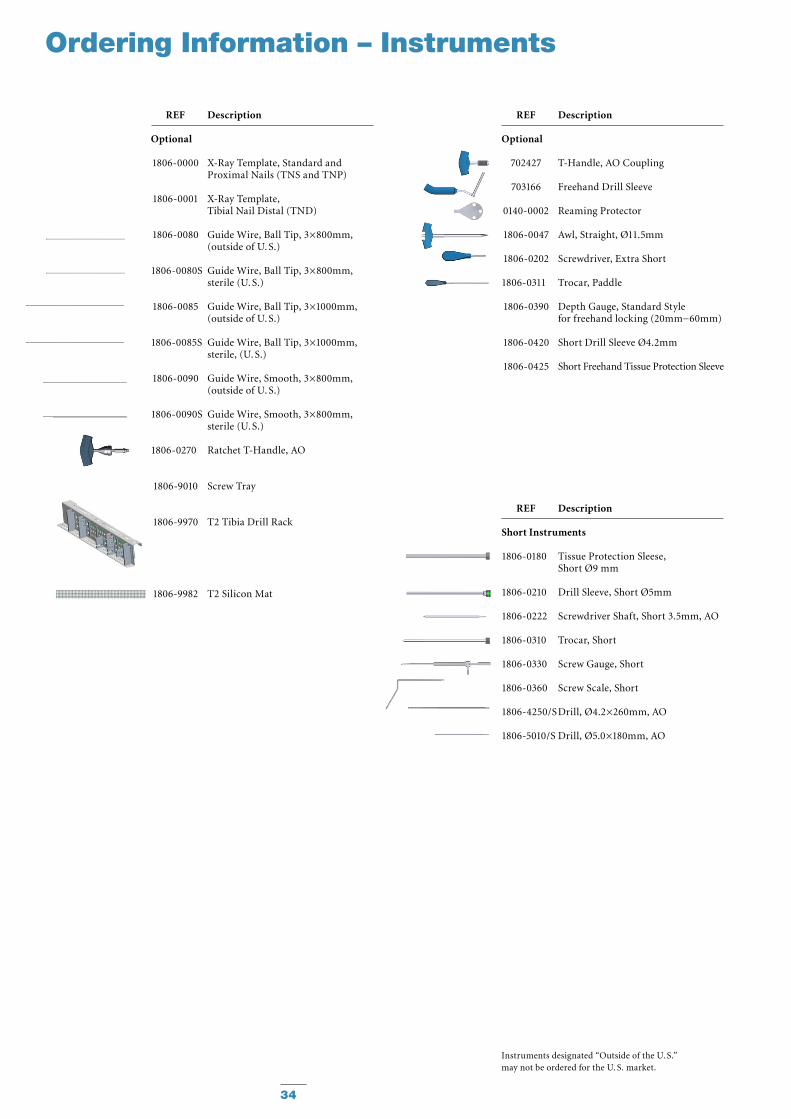
Optional
1806-0000 X-Ray Template, Standard and Proximal Nails (TNS and TNP)
1806-0001 X-Ray Template, Tibial Nail Distal (TND)
1806-0080 Guide Wire, Ball Tip, 3×800mm, (outside of U. S.)
1806-0080S Guide Wire, Ball Tip, 3×800mm, sterile (U. S.)
1806-0085 Guide Wire, Ball Tip, 3×1000mm, (outside of U. S.)
1806-0085S Guide Wire, Ball Tip, 3×1000mm, sterile, (U. S.)
1806-0090 Guide Wire, Smooth, 3×800mm, (outside of U. S.)
1806-0090S Guide Wire, Smooth, 3×800mm, sterile (U. S.)
1806-0270 Ratchet T-Handle, AO
1806-9010 Screw Tray
1806-9970 T2 Tibia Drill Rack
1806-9982 T2 Silicon Mat
REF Description
Optional
702427 T-Handle, AO Coupling
703166 Freehand Drill Sleeve
0140-0002 Reaming Protector
1806-0047 Awl, Straight, Ø11.5mm
1806-0202 Screwdriver, Extra Short
1806-0311 Trocar, Paddle
1806-0390 Depth Gauge, Standard Style for freehand locking (20mm−60mm)
1806-0420 Short Drill Sleeve Ø4.2mm
1806-0425 Short Freehand Tissue Protection Sleeve
REF Description
Short Instruments
1806-0180 Tissue Protection Sleese, Short Ø9 mm
1806-0210 Drill Sleeve, Short Ø5mm
1806-0222 Screwdriver Shaft, Short 3.5mm, AO
1806-0310 Trocar, Short
1806-0330 Screw Gauge, Short
1806-0360 Screw Scale, Short
1806-4250/S Drill, Ø4.2×260mm, AO
1806-5010/S Drill, Ø5.0×180mm, AO
Instruments designated “Outside of the U. S.” may not be ordered for the U. S. market.
Ordering Information – Instruments

35
Complete range of modular and fixed-head reamers to match surgeon preference and optimize O. R. efficiency, presented in fully sterilizable cases.
Studies1 have demonstrated that the pressures developed within the medullary cavity through the introduction of unreamed IMnails can be far greater than those devel oped during reaming − but this depends very much upon the design of the reamer.
After a three year development study2 involving several universities, the factors that determine the pressures and temperatures developed during reaming were clearly established. These factors were applied to the de -velopment of advanced reamers that demonstrate significantly better per -form ance than the best of previous designs3.
1 Jan Paul M. Frolke, et al. ; Intramedullary Pressure in Reamed Femoral
Nailing with Two Different Reamer Designs., Eur. J. of Trauma, 2001 #5
2 Medhi Moussavi, et al.; Pressure Changes During Reaming with Different
Parameters and Reamer Designs, Clinical Orthopaedics and Related Research
Number 373, pp. 295-303, 2000
3 Andreas Speitling; Intramedullary Reamers, commented slides of internal test report, Sep 1999
Large clearance rate resulting from reduced number of reamer blades coupled with reduced length of reamer head to allow for effective relief of pressure and efficient removal of material3.
Cutting flute geometry optimized to lower pressure generation3.
Forward- and side-cutting face combination produces efficient material removal and rapid clearance3.
Double-wound shaft transmits torque effectively and with high reliability. Low-friction surface finish aids rapid debris clearance3.
Smaller, 6 and 8mm shaft diameters are designed to reduce IM pressure.
Typical StandardReamer Ø14mm
Clearance area :32% of cross section
BixcutReamer Ø14mm
Clearance area :59% of cross section
Ordering Information – Instruments
Bixcut
Bixcut

36
REF Description Diameter mm
BIxCuT MODuLAR HEAD
REF Diameter Length mm mm
BIxCuT FIxED HEAD − AO FITTINg**
REF Description Length mm
BIxCuT SHAFTS (STERILE)1,2,3, 4
REF Description
SHAFT ACCESSORIES
REF Description
BIxCuT TRAyS EMPTy
Ordering Information – Instruments
REF Description
OPTIONAL INSTRuMENTS
0227-0060 Hand Reamer 6 mm w/Mod Trinkle connection
0227-0070 Hand Reamer 7 mm w/Mod Trinkle connection
0227-0080 Hand Reamer 8 mm w/Mod Trinkle connection
0227-0090 Hand Reamer 9 mm w/Mod Trinkle connection
1806-6520 Curved Reduction Rod 8.5 mm w/Mod Trinkle connection
1806-6500 T-Handle w/Mod Trinkle connection
0226-30900226-30950226-31000226-31050226-31100226-31150226-31200226-31250226-31300226-31350226-31400226-31450226-31500226-31550226-31600226-31650226-31700226-31750226-31800226-41850226-41900226-41950226-42000226-42050226-42100226-42150226-42200226-42250226-42300226-42350226-42400226-42450226-42500226-42550226-42600226-42650226-42700226-42750226-4280
Bixcut HeadBixcut HeadBixcut HeadBixcut HeadBixcut HeadBixcut HeadBixcut HeadBixcut HeadBixcut HeadBixcut HeadBixcut HeadBixcut HeadBixcut HeadBixcut HeadBixcut HeadBixcut HeadBixcut HeadBixcut HeadBixcut HeadBixcut HeadBixcut HeadBixcut HeadBixcut HeadBixcut HeadBixcut HeadBixcut HeadBixcut HeadBixcut HeadBixcut HeadBixcut HeadBixcut HeadBixcut HeadBixcut HeadBixcut HeadBixcut HeadBixcut HeadBixcut HeadBixcut HeadBixcut Head
9.09.5
10.010.511.011.512.012.513.013.514.014.515.015.516.016.517.017.518.018.519.019.520.020.521.021.522.022.523.023.524.024.525.025.526.026.527.027.528.0
0227-8240S Mod. Trinkle 284 0227-3000S Mod. Trinkle 448 0227-8510S Mod. Trinkle 510 0227-8885S Mod. Trinkle 885 0226-8240S AO 284 0226-3000S AO 448 0225-6000 Tray, Modular Head
(up to size 22.0mm) 0225-6001 Tray, Modular Head (up to size 28.0mm) 0225-8000 Tray, Fixed Head (up to size 18.0mm) 0225-6040 Mini Trauma Tray (for modular heads 9-18) 0225-6050 Mini Revision Tray (for modular heads 9-28)
0225-50600225-50650225-50700225-60750225-60800225-60850225-60900225-60950225-61000225-61050225-61100225-81150225-81200225-81250225-81300225-81350225-81400225-81450225-81500225-81550225-81600225-81650225-81700225-81750225-8180
6.0*6.5*7.0*7.58.08.59.09.5
10.010.511.011.512.012.513.013.514.014.515.015.516.016.517.017.518.0
400400400480480480480480480480480480480480480480480480480480480480480480480
3212-0-210 Grommet (pack of 25) 3212-0-220 Grommet inserter/extractor 0225-6010 Grommet Case
Note:
Bixcut Fixed Head − Modified Trinkle fitting available in same diameters and length as the AO Fitting (REF No: 0227-xxxx)
* Use with 2.2mm × 800mm Smooth Tip and 2.5mm × 800mm Ball Tip Guide Wires only.** Use with Stryker Power Equipment.1. Non-Sterile shafts supplied without grommet. Use new grommet for each surgery. See Shaft
Accessories.2. Sterile shafts supplied with grommet pre-assembled.3. For Non-Sterile leave “S” off the REF Number when ordering (510 and 885mm available only sterile
Modified Trinkle Fitting).4. Non-Sterile, AO Fitting Shafts in 510 and 885mm are available as build to order items:
CM810921 AO Fitting Shaft, length 510mm• CM810923 AO Fitting Shaft, length 885mm.•

37
Notes

38
Notes

39
Notes

Stryker Trauma GmbHProf.-Küntscher-Straße 1–5D - 24232 SchönkirchenGermany
www.osteosynthesis.stryker.com
This document is intended solely for the use of healthcare professionals. A surgeon must always rely on his or her own professional clinical judgment when deciding whether to use a particular product when treating a particular patient. Stryker does not dispense medical advice and recommends that surgeons be trained in the use of any par-ticular product before using it in surgery. The information presented in this brochure is intended to demonstrate a Stryker product. Always refer to the package insert, product label and/or user instructions including the instructions for Cleaning and Sterilization (if applicable) before using any Stryker products. Products may not be available in all markets. Product availability is subject to the regulatory or medical practices that govern individual markets. Please contact your Stryker representative if you have questions about the availability of Stryker products in your area.
Stryker Corporation or its divisions or other corporate affiliated entities own, use or have applied for the following trademarks or service marks: Stryker, T2 and BixCut.
All other trademarks are trademarks of their respective owners or holders.The products listed above are CE marked.
Literature Number : B1000005LOT H0710
Copyright © 2010 Stryker