t2 femoral nailing system
TRANSCRIPT
Operative Technique
T2 Femoral Nailing System

2
Contributing Surgeons
Prof. Dr. med. Volker BührenChief of Surgical ServicesMedical Director of Murnau Trauma CenterMurnauGermany
Joseph D. DiCicco III, D. O.Director Orthopaedic Trauma ServiceGood Samaritan Hospital Dayton, OhioAssociate Clinical Professor of Orthopeadic SurgeryOhio University and Wright State UniversityUSA
Thomas G. DiPasquale, D. O.Medical Director, Orthopedic Trauma Services Director, Orthopedic Trauma Fellowship andOrthopedic Residency ProgramsYork HospitalYorkUSA
This publication sets forth detailed recommended procedures for using Stryker Osteosynthesis devices and instruments.
It offers guidance that you should heed, but, as with any such technical guide, each surgeon must consider the particular needs of each patient and make appropriate adjustments when and as required.
A workshop training is required prior to first surgery.
All non-sterile devices must be cleaned and sterilized before use. Follow the instructions provided in our reprocessing guide (L24002000). Multi-component instruments must be disassembled for cleaning. Please refer to the corresponding assembly/disassembly instructions.
See package insert (L22000007) for a complete list of potential adverse effects, contraindications, warnings and precautions. The surgeon must discuss all relevant risks, including the finite lifetime of the device, with the patient, when necessary.
Warning: Fixation Screws:Stryker Ostreosynthesis bone screws are not approved or intended for screw attachment or fixation to the posterior elements (pedicles) of the cervical, thoracic or lumbar spine.
Femoral Nailing System
Page
1. Introduction 4
Implant Features 4
Instrument Features 6
References 6
2. Indications, Precautions and Contraindications 7
Indications 7
Precautions 7
Relative Contraindications 7
3. Additional Information 8
Locking Options 8
4. Pre-operative Planning 10
5. Operative Technique – Retrograde Technique 11
Patient Positioning 11
Incision 11
Entry Point 12
Unreamed Technique 13
Reamed Technique 13
Nail Selection 15
Nail Insertion 16
Guided Locking Mode (via Target Device) 18
Static Locking Mode 19
Freehand Proximal Locking 23
End Cap Insertion 25
Dynamic Locking Mode 26
Apposition /Compression Locking Mode 26
Advanced Locking Mode 28
External Compression Device 30
Nail Removal 32
6. Operative Technique – Antegrade Technique 33
Patient Positioning and Fracture Reduction 33
Incision 33
Entry Point 34
Unreamed Technique 35
Reamed Technique 35
Nail Selection 37
Nail Insertion 38
Guided Locking Mode (via Target Device) 40
Static Locking Mode 41
Freehand Distal Locking 43
End Cap Insertion 44
Dynamic Locking Mode 45
Apposition /Compression Locking Mode 46
Advanced Locking Mode 48
External Compression Device 48
Nail Removal 50
Ordering Information – Implants 51
Ordering Information – Instruments 54
3
Contents
4
Introduction
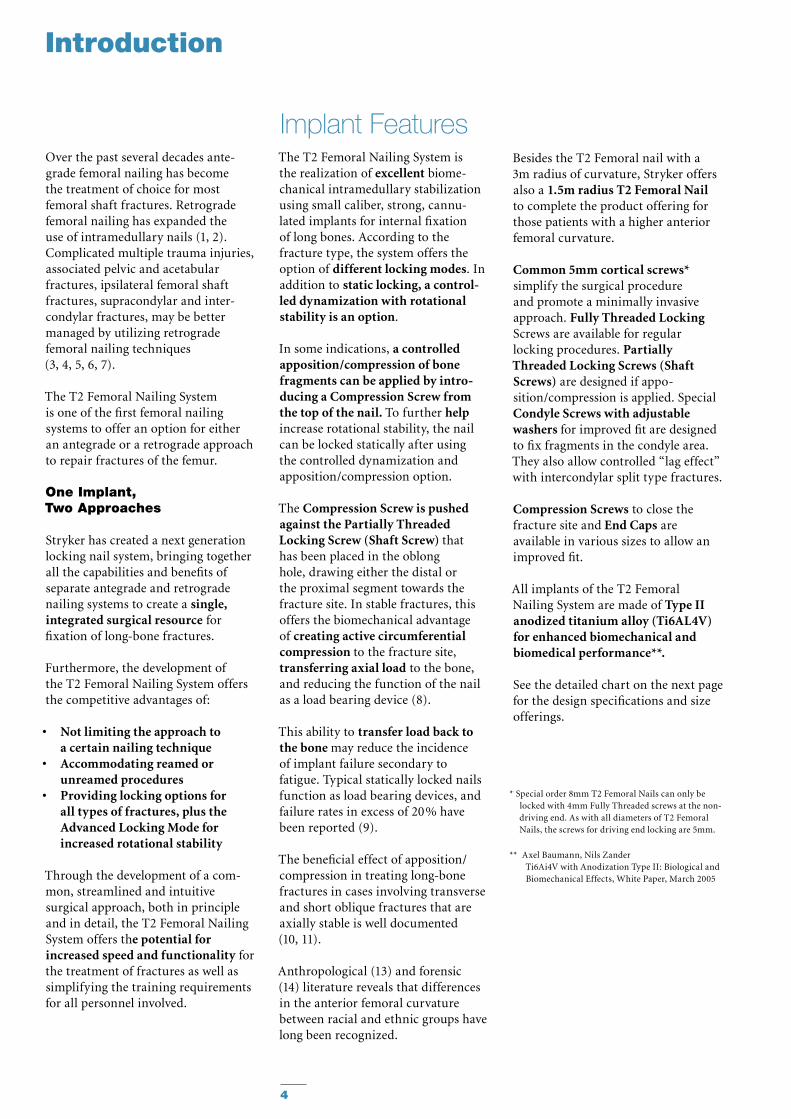
Over the past several decades ante-grade femoral nailing has become the treatment of choice for most femoral shaft fractures. Retrograde femoral nailing has expanded the use of intramedullary nails (1, 2). Complicated multiple trauma injuries, associated pelvic and acetabular frac tures, ipsilateral femoral shaft fractures, supracondylar and inter-condylar fractures, may be better managed by utilizing retrograde femoral nailing techniques (3, 4, 5, 6, 7).
The T2 Femoral Nailing System is one of the first femoral nailing systems to offer an option for either an antegrade or a retrograde ap proach to repair fractures of the femur.
One Implant, Two Approaches
Stryker has created a next generation locking nail system, bringing together all the capabilities and benefits of separate antegrade and retrograde nailing systems to create a single, integrated surgical resource for fixation of long-bone fractures.
Furthermore, the development of the T2 Femoral Nailing System offers the competitive advantages of:
• Not limiting the approach to a certain nailing technique
• Accommodating reamed or unreamed procedures
• Providing locking options for all types of fractures, plus the Advanced Locking Mode for increased rotational stability
Through the development of a com-mon, streamlined and intuitive surgical approach, both in principle and in detail, the T2 Femoral NailingSystem offers the potential for increased speed and functionality for the treatment of fractures as well as simplifying the training requirements for all personnel involved.
Besides the T2 Femoral nail with a 3m radius of curvature, Stryker offers also a 1.5m radius T2 Femoral Nail to complete the product offering for those patients with a higher anterior femoral curvature.
Common 5mm cortical screws* sim plify the surgical procedure and promote a minimally invasive approach. Fully Threaded Locking Screws are available for regular locking procedures. Partially Threaded Locking Screws (Shaft Screws) are designed if appo- sition/compression is applied. Special Condyle Screws with adjustable washers for improved fit are designed to fix fragments in the condyle area. They also allow controlled “lag effect” with intercondylar split type fractures.
Compression Screws to close the fracture site and End Caps are available in various sizes to allow an improved fit.
All implants of the T2 Femoral Nailing System are made of Type II anodized titanium alloy (Ti6AL4V) for enhanced biomechanical and biomedical performance**.
See the detailed chart on the next page for the design specifications and size offerings.
* Special order 8mm T2 Femoral Nails can only be locked with 4mm Fully Threaded screws at the non-driving end. As with all diameters of T2 Femoral Nails, the screws for driving end locking are 5mm.
** Axel Baumann, Nils Zander Ti6Ai4V with Anodization Type II: Biological and Biomechanical Effects, White Paper, March 2005
The T2 Femoral Nailing System is the realization of excellent biome-chanical intramedullary stabilization using small caliber, strong, cannu-lated implants for internal fixation of long bones. According to the frac ture type, the system offers the option of different locking modes. In addition to static locking, a control-led dynamization with rotational stability is an option.
In some indications, a controlled apposition/compression of bone fragments can be applied by intro-ducing a Compression Screw from the top of the nail. To further help in crease rotational stability, the nail can be locked statically after using the controlled dynamization and apposition/compression option.
The Compression Screw is pushed against the Partially Threaded Locking Screw (Shaft Screw) that has been placed in the oblong hole, drawing either the distal or the proximal segment towards the fracture site. In stable fractures, this offers the biomechanical advantage of creating active circumferential compression to the fracture site, transferring axial load to the bone, and reducing the function of the nail as a load bearing device (8).
This ability to transfer load back to the bone may reduce the incidence of implant failure secondary to fatigue. Typical statically locked nails function as load bearing devices, and failure rates in excess of 20 % have been re ported (9).
The beneficial effect of apposition/compression in treating long-bone fractures in cases involving transverse and short oblique fractures that are axially stable is well documented (10, 11).
Anthropological (13) and forensic (14) literature reveals that differences in the anterior femoral curvature between racial and ethnic groups have long been recognized.
Implant Features
5
Introduction
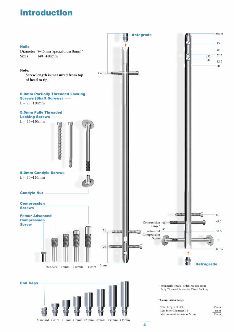
NailsDiameter 9−15mm (special order 8mm)*Sizes 140−480mm
Note: Screw length is measured from top of head to tip.
Standard +5mm +10mm +15mm
Standard +5mm +10mm +15mm +20mm +25mm +30mm +35mm
45mm
Antegrade
50
25
0mm
* 8mm nails (special order) require 4mm Fully Threaded Screws for Distal Locking
* Compression Range
Total Length of Slot 15mmLess Screw Diameter (-) 5mmMaximum Movement of Screw 10mm
60
47.5
32.5
15
0mm
0mm
25
15
42.5
50
32.53540
Retrograde
Advanced Compression
Screw
45
35
Compression Range*
Condyle Nut
5.0mm Fully ThreadedLocking ScrewsL = 25−120mm
Compression Screws
Femur AdvancedCompression Screw
End Caps
5.0mm Partially Threaded Locking Screws (Shaft Screws)L = 25−120mm
5.0mm Condyle ScrewsL = 40−120mm
6
Introduction
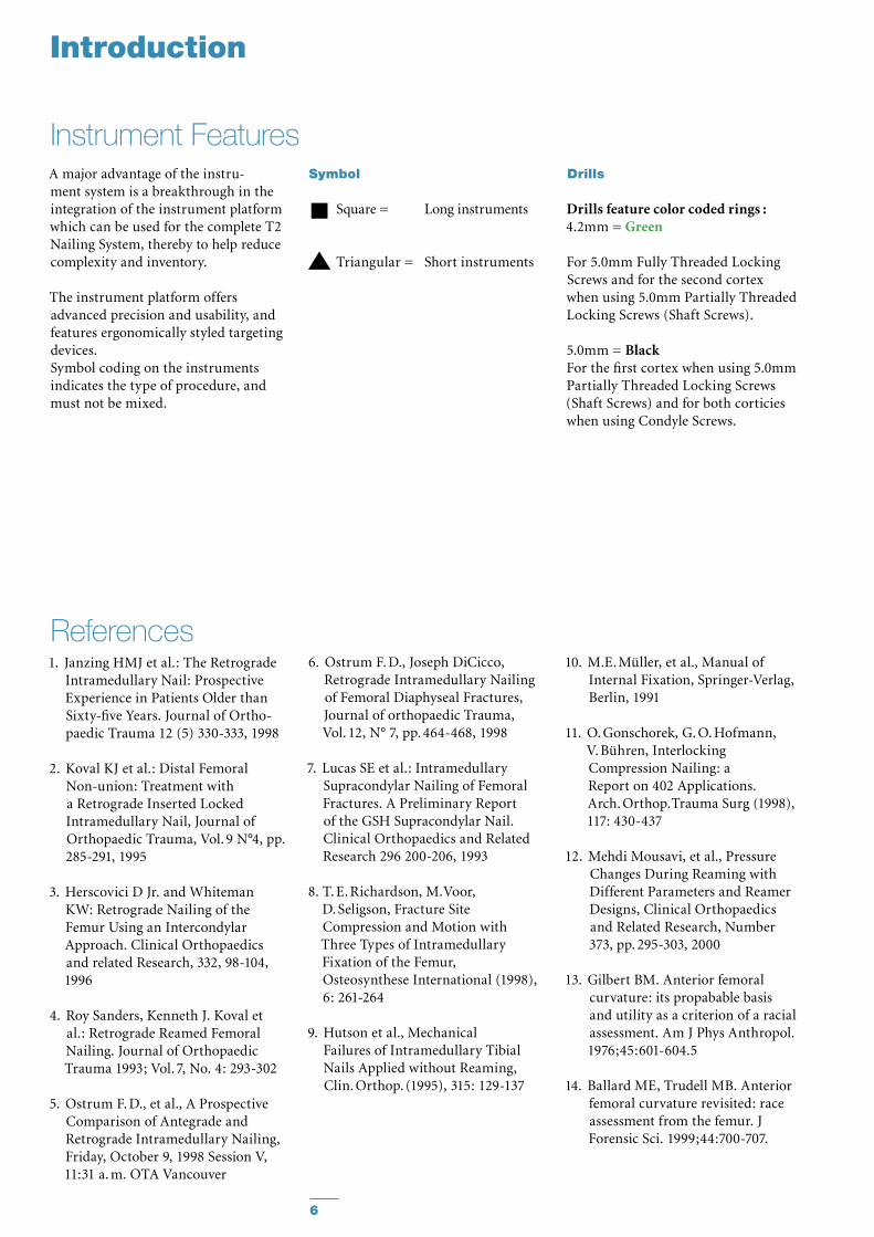
A major advantage of the instru-ment system is a breakthrough in the integration of the instrument plat form which can be used for the complete T2 Nailing System, thereby to help reduce complexity and inventory.
The instrument platform offers ad vanced precision and usability, and features ergonomically styled targeting devices.Symbol coding on the instruments indicates the type of procedure, and must not be mixed.
Instrument FeaturesDrills
Drills feature color coded rings :4.2mm = Green
For 5.0mm Fully Threaded Locking Screws and for the second cortex when using 5.0mm Partially Threaded Locking Screws (Shaft Screws).
5.0mm = BlackFor the first cortex when using 5.0mm Partially Threaded Locking Screws (Shaft Screws) and for both corticies when using Condyle Screws.
10. M.E. Müller, et al., Manual of Internal Fixation, Springer-Verlag, Berlin, 1991
11. O. Gonschorek, G. O. Hofmann, V. Bühren, Interlocking Compression Nailing: a Report on 402 Applications. Arch. Orthop. Trauma Surg (1998), 117: 430-437
12. Mehdi Mousavi, et al., Pressure Changes During Reaming with Different Parameters and Reamer Designs, Clinical Orthopaedics and Related Research, Number 373, pp. 295-303, 2000
13. Gilbert BM. Anterior femoral curvature: its propabable basis and utility as a criterion of a racial assessment. Am J Phys Anthropol. 1976;45:601-604.5
14. Ballard ME, Trudell MB. Anterior femoral curvature revisited: race assessment from the femur. J Forensic Sci. 1999;44:700-707.
1. Janzing HMJ et al.: The Retrograde Intramedullary Nail: Prospective Experience in Patients Older than Sixty-five Years. Journal of Ortho-paedic Trauma 12 (5) 330-333, 1998
2. Koval KJ et al.: Distal Femoral Non-union: Treatment with a Retrograde Inserted Locked Intramedullary Nail, Journal of Orthopaedic Trauma, Vol. 9 N°4, pp. 285-291, 1995
3. Herscovici D Jr. and Whiteman KW: Retrograde Nailing of the Femur Using an Intercondylar Approach. Clinical Orthopaedics and related Research, 332, 98-104, 1996
4. Roy Sanders, Kenneth J. Koval et al.: Retrograde Reamed Femoral Nailing. Journal of Orthopaedic Trauma 1993; Vol. 7, No. 4: 293-302
5. Ostrum F. D., et al., A Prospective Comparison of Antegrade and Retrograde Intramedullary Nailing, Friday, October 9, 1998 Session V, 11:31 a. m. OTA Vancouver
References6. Ostrum F. D., Joseph DiCicco,
Retrograde In tramedullary Nailing of Femoral Diaphyseal Fractures, Journal of orthopaedic Trauma, Vol. 12, N° 7, pp. 464-468, 1998
7. Lucas SE et al.: Intramedullary Supracondylar Nailing of Femoral Fractures. A Preliminary Report of the GSH Supracondylar Nail. Clinical Orthopaedics and Related Research 296 200-206, 1993
8. T. E. Richardson, M. Voor, D. Seligson, Fracture Site Compression and Motion with Three Types of Intramedullary Fixation of the Femur, Osteosynthese International (1998), 6: 261-264
9. Hutson et al., Mechanical Failures of Intramedullary Tibial Nails Applied without Reaming, Clin. Orthop. (1995), 315: 129-137
Symbol
Square = Long instruments
Triangular = Short instruments
7
Open and closed femoral •fracturesPseudarthrosis and Correction •OsteotomyPathologic fractures, impending •pathologic fractures and tumor resectionsSupracondylar fractures, •including those with intraarticular extensionIpsilateral femur fractures•Fractures proximal to a total knee •arthroplastyFractures distal to a hip joint•Nonunions and malunions.•
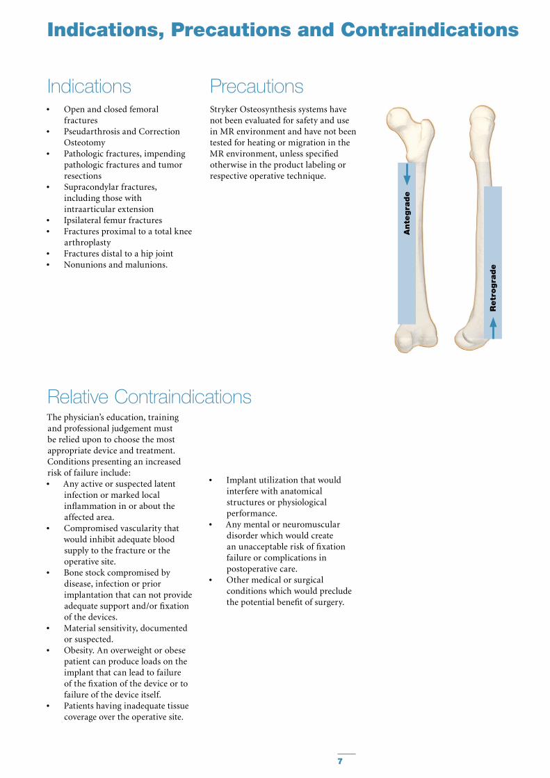
Indications Precautions
The physician’s education, training and professional judgement must be relied upon to choose the most appropriate device and treatment. Conditions presenting an increased risk of failure include:
Any active or suspected latent •infection or marked local inflammation in or about the affected area.Compromised vascularity that •would inhibit adequate blood supply to the fracture or the operative site.Bone stock compromised by •disease, infection or prior implantation that can not provide adequate support and/or fixation of the devices.Material sensitivity, documented •or suspected.Obesity. An overweight or obese •patient can produce loads on the implant that can lead to failure of the fixation of the device or to failure of the device itself.Patients having inadequate tissue •coverage over the operative site.
Relative Contraindications
Indications, Precautions and Contraindications
Ante
gra
de
Retr
ogra
de
Implant utilization that would •interfere with anatomical structures or physiological performance.Any mental or neuromuscular •disorder which would create an unacceptable risk of fixation failure or complications in postoperative care.Other medical or surgical •conditions which would preclude the potential benefit of surgery.
Stryker Osteosynthesis systems have not been evaluated for safety and use in MR environment and have not been tested for heating or migration in the MR environment, unless specified otherwise in the product labeling or respective operative technique.
8
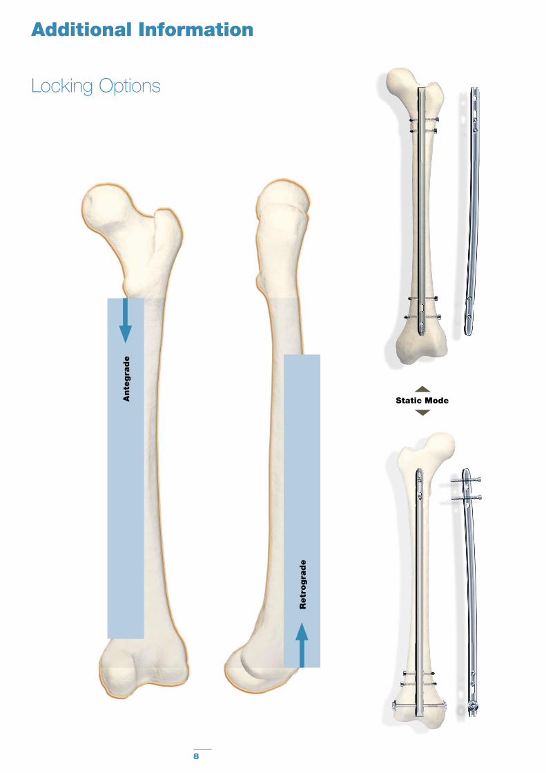
Static Mode
Additional Information
Locking Options
Ante
gra
de
Retr
ogra
de
9
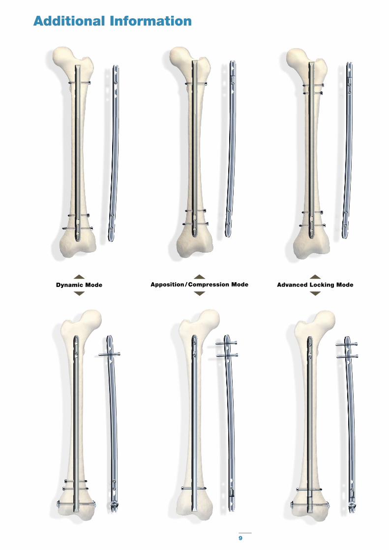
Dynamic Mode Apposition / Compression Mode Advanced Locking Mode
Additional Information
10
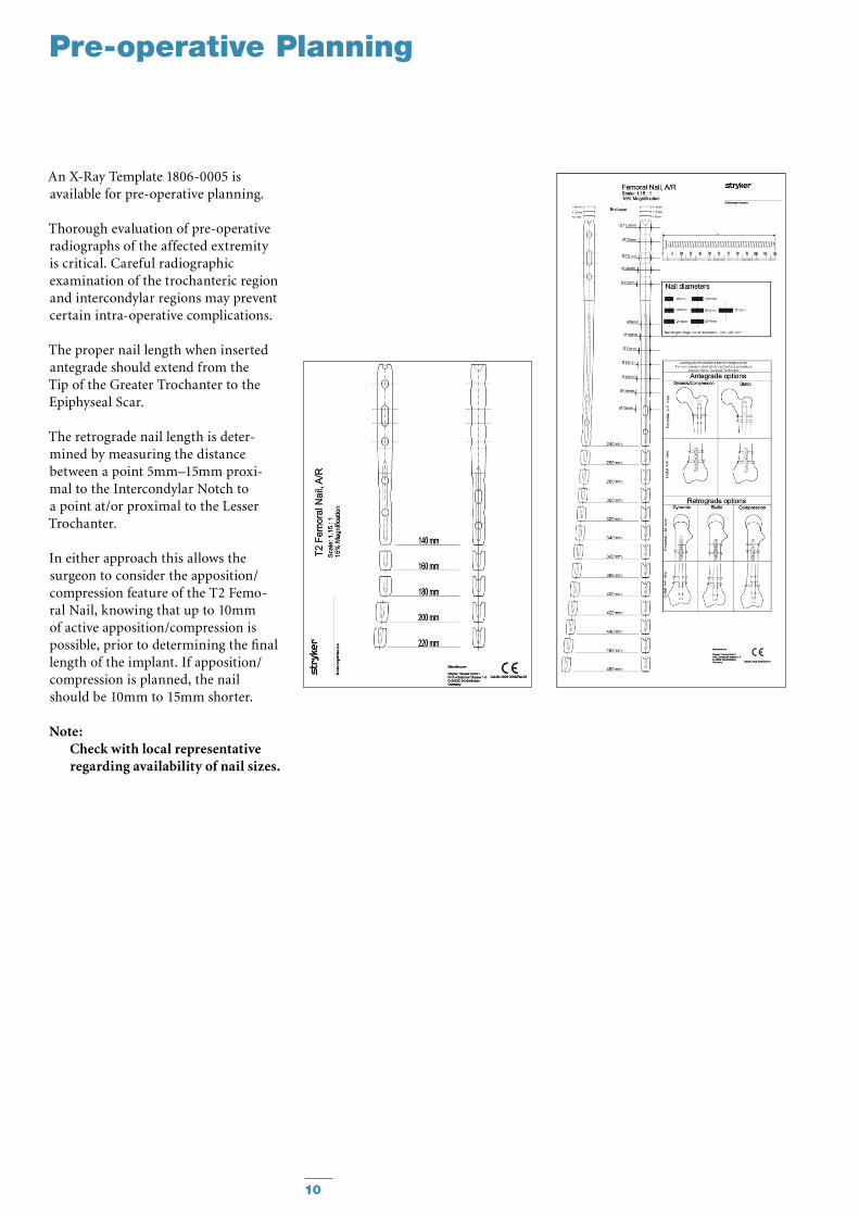
An X-Ray Template 1806-0005 is available for pre-operative planning.
Thorough evaluation of pre-operative radiographs of the affected extrem ity is critical. Careful radiographic ex am ination of the trochanteric region and intercondylar regions may prevent certain intra-operative complications.
The proper nail length when inserted antegrade should extend from the Tip of the Greater Trochanter to the Epiphyseal Scar.
The retrograde nail length is deter-mined by measuring the distance between a point 5mm–15mm proxi-mal to the Intercondylar Notch to a point at/or proximal to the Lesser Trochanter.
In either approach this allows the surgeon to consider the apposition/compression feature of the T2 Femo-ral Nail, knowing that up to 10mm of active apposition/compression is possible, prior to determining the final length of the implant. If apposition/compression is planned, the nail should be 10mm to 15mm shorter.
Note: Check with local representative regarding availability of nail sizes.
Pre-operative Planning
11
Operative Technique – Retrograde Technique
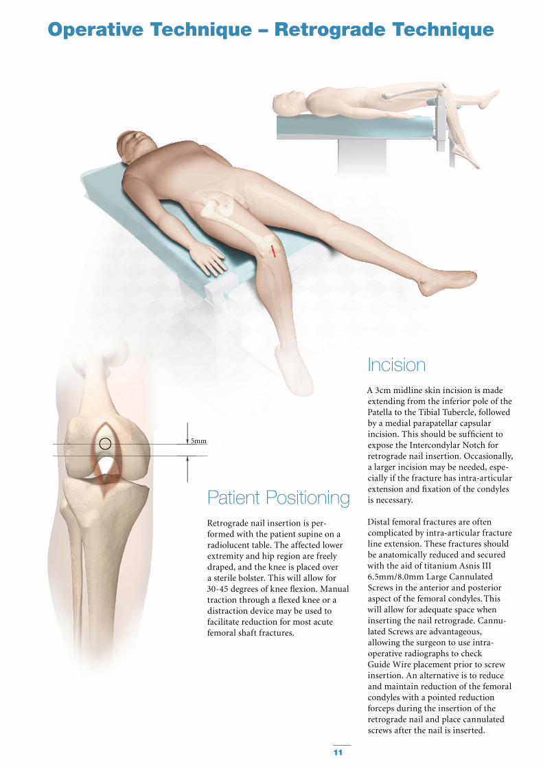
IncisionA 3cm midline skin incision is made extending from the inferior pole of the Patella to the Tibial Tubercle, followed by a medial parapatellar capsular in ci sion. This should be sufficient to expose the Intercondylar Notch for retrograde nail insertion. Occasionally, a larger incision may be needed, espe-cially if the fracture has intra-articular extension and fixation of the condyles is necessary.
Distal femoral fractures are often complicated by intra-articular fracture line extension. These fractures should be anatomically reduced and secured with the aid of titanium Asnis III 6.5mm/8.0mm Large Cannulated Screws in the anterior and posterior aspect of the femoral condyles. This will allow for adequate space when inserting the nail retrograde. Cannu-lated Screws are advantageous, al low ing the surgeon to use intra-operative radiographs to check Guide Wire place ment prior to screw insertion. An alternative is to reduce and maintain reduction of the femoral condyles with a pointed reduction forceps during the insertion of the retrograde nail and place cannulated screws after the nail is inserted.
Patient PositioningRetrograde nail insertion is per-formed with the patient supine on a radiolucent table. The affected lower extremity and hip region are freely draped, and the knee is placed over a sterile bolster. This will allow for 30-45 degrees of knee flexion. Manual traction through a flexed knee or a distraction device may be used to facilitate reduction for most acute femoral shaft fractures.
5mm
12
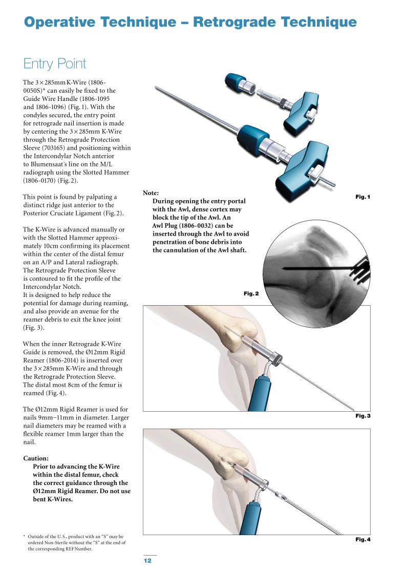
The 3 × 285mm K-Wire (1806-0050S)* can easily be fixed to the Guide Wire Handle (1806-1095 and 1806-1096) (Fig. 1). With the condyles secured, the entry point for retrograde nail in ser tion is made by centering the 3 × 285mm K-Wire through the Retrograde Protection Sleeve (703165) and positioning within the Intercondylar Notch anterior to Blumensaat s line on the M/L radiograph using the Slotted Hammer (1806-0170) (Fig. 2).
This point is found by palpating a distinct ridge just anterior to the Posterior Cruciate Ligament (Fig. 2).
The K-Wire is advanced manually or with the Slotted Hammer ap prox i-mately 10cm confirming its place ment within the center of the distal femur on an A/P and Lateral radiograph.The Retrograde Protection Sleeve is contoured to fit the profile of the Intercondylar Notch. It is designed to help reduce the potential for damage during reaming, and also provide an avenue for the reamer debris to exit the knee joint (Fig. 3).
When the inner Retrograde K-Wire Guide is removed, the Ø12mm Rigid Reamer (1806-2014) is inserted over the 3 × 285mm K-Wire and through the Retrograde Protection Sleeve. The distal most 8cm of the femur is reamed (Fig. 4).
The Ø12mm Rigid Reamer is used for nails 9mm−11mm in diameter. Larger nail diameters may be reamed with a flexible reamer 1mm larger than the nail.
Caution: Prior to advancing the K-Wire within the distal femur, check the correct guidance through the Ø12mm Rigid Reamer. Do not use bent K-Wires.
Entry Point
Fig. 1
Fig. 3
Fig. 4
Note:During opening the entry portal with the Awl, dense cortex may block the tip of the Awl. An Awl Plug (1806-0032) can be inserted through the Awl to avoid penetration of bone debris into the cannulation of the Awl shaft.
Operative Technique – Retrograde Technique
Fig. 2
* Outside of the U. S., product with an “S” may be ordered Non-Sterile without the “S” at the end of the corresponding REF Number.
13
Operative Technique – Retrograde Technique
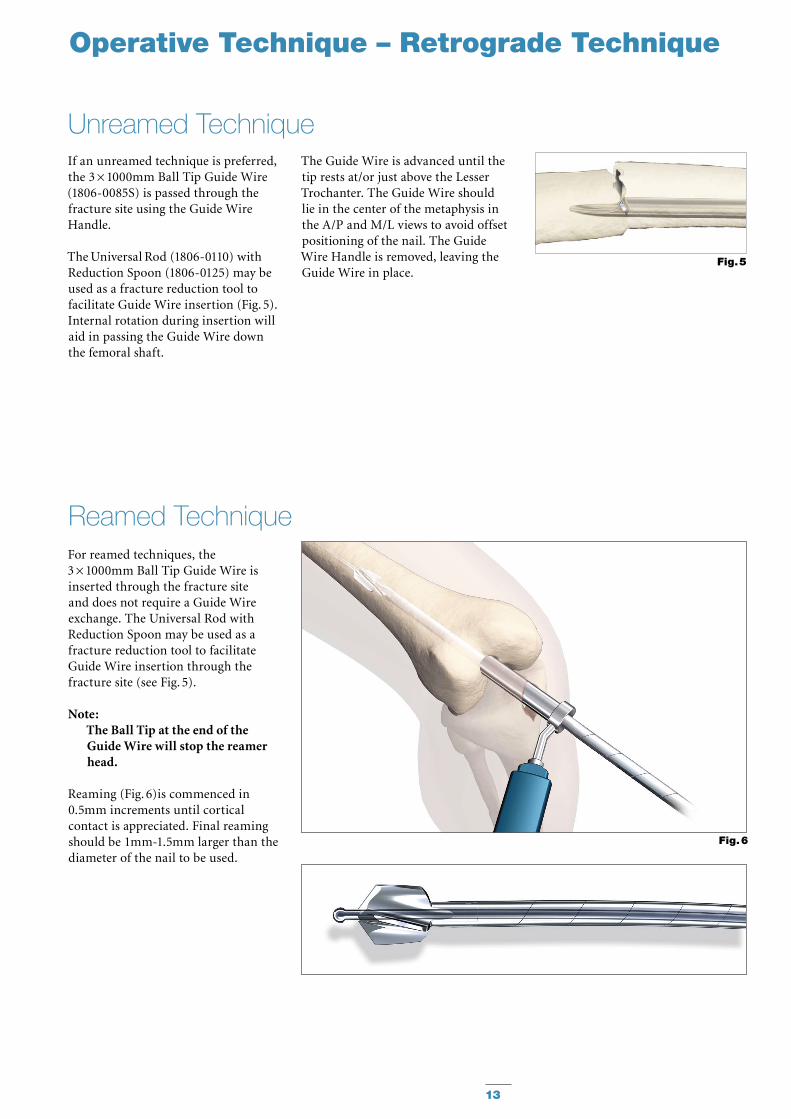
If an unreamed technique is pre ferred, the 3 × 1000mm Ball Tip Guide Wire (1806-0085S) is passed through the fracture site using the Guide Wire Handle.
The Universal Rod (1806-0110) with Reduction Spoon (1806-0125) may be used as a fracture reduction tool to facilitate Guide Wire insertion (Fig. 5). Internal rotation during insertion will aid in passing the Guide Wire down the femoral shaft.
For reamed techniques, the3 × 1000mm Ball Tip Guide Wire is inserted through the fracture site and does not require a Guide Wire exchange. The Universal Rod with Reduction Spoon may be used as a fracture reduction tool to facilitate Guide Wire insertion through the fracture site (see Fig. 5).
Note: The Ball Tip at the end of the Guide Wire will stop the reamer head.
Reaming (Fig. 6)is commenced in 0.5mm increments until cortical contact is appreciated. Final reaming should be 1mm-1.5mm larger than the diameter of the nail to be used.
Reamed Technique
Unreamed Technique
Fig. 6
Fig. 5
The Guide Wire is advanced until the tip rests at/or just above the Lesser Trochanter. The Guide Wire should lie in the center of the metaphysis in the A/P and M/L views to avoid offset positioning of the nail. The Guide Wire Handle is removed, leaving the Guide Wire in place.
14
Operative Technique – Retrograde Technique
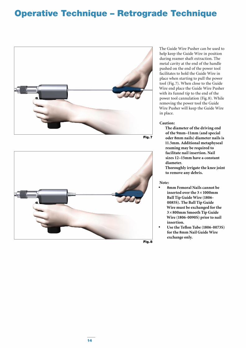
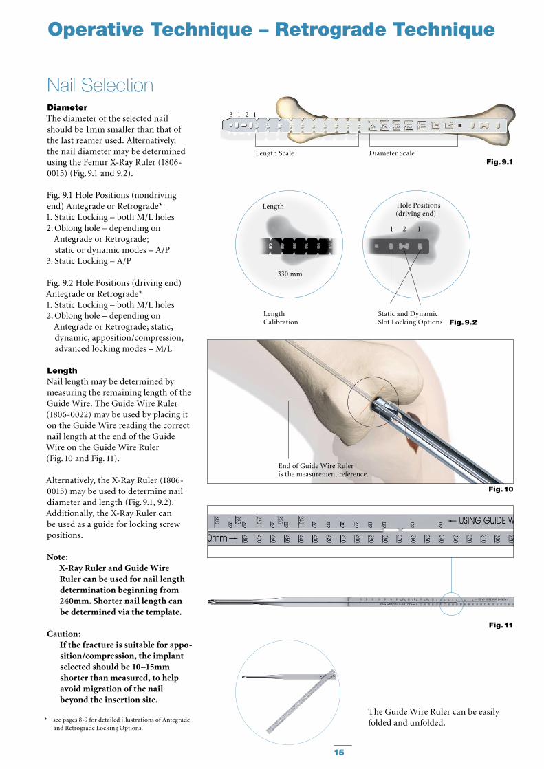
The Guide Wire Pusher can be used to help keep the Guide Wire in position during reamer shaft extraction. The metal cavity at the end of the handle pushed on the end of the power tool facilitates to hold the Guide Wire in place when starting to pull the power tool (Fig. 7). When close to the Guide Wire end place the Guide Wire Pusher with its funnel tip to the end of the power tool cannulation (Fig. 8). While removing the power tool the Guide Wire Pusher will keep the Guide Wire in place.
Caution: The diameter of the driving end of the 9mm–11mm (and special oder 8mm nails) diameter nails is 11.5mm. Additional metaphyseal reaming may be required to facilitate nail insertion. Nail sizes 12–15mm have a constant diameter.Thoroughly irrigate the knee joint to remove any debris.
Note:8mm Femoral Nails cannot be •inserted over the 3 × 1000mm Ball Tip Guide Wire (1806-0085S). The Ball Tip Guide Wire must be exchanged for the 3 × 800mm Smooth Tip Guide Wire (1806-0090S) prior to nail insertion.Use the Teflon Tube (1806-0073S) •for the 8mm Nail Guide Wire exchange only.
Fig. 7
Fig. 8
15
Fig. 11
Length
330 mm
Length Calibration Fig. 9.2
Hole Positions(driving end)
Static and Dynamic Slot Locking Options
1 2 1
Fig. 10
End of Guide Wire Ruler is the measurement reference.
Operative Technique – Retrograde Technique
The Guide Wire Ruler can be easily folded and unfolded.
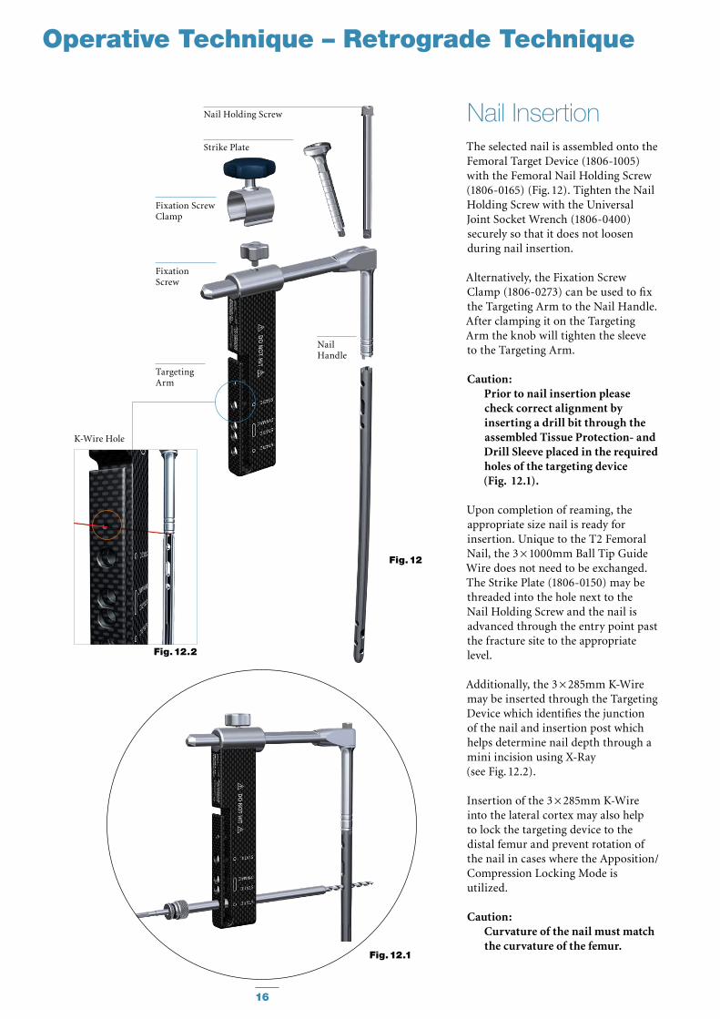
DiameterThe diameter of the selected nail should be 1mm smaller than that of the last reamer used. Alternatively, the nail diameter may be determined using the Femur X-Ray Ruler (1806-0015) (Fig. 9.1 and 9.2).
Fig. 9.1 Hole Positions (nondriving end) Antegrade or Retrograde*1. Static Locking – both M/L holes2. Oblong hole – depending on
Antegrade or Retrograde; static or dynamic modes – A/P
3. Static Locking – A/P
Fig. 9.2 Hole Positions (driving end) Antegrade or Retrograde*1. Static Locking – both M/L holes2. Oblong hole – depending on
Antegrade or Retrograde; static, dynamic, apposition/compres sion, advanced locking modes – M/L
LengthNail length may be determined by measuring the remaining length of the Guide Wire. The Guide Wire Ruler (1806-0022) may be used by placing it on the Guide Wire reading the correct nail length at the end of the Guide Wire on the Guide Wire Ruler (Fig. 10 and Fig. 11).
Alternatively, the X-Ray Ruler (1806-0015) may be used to determine nail diameter and length (Fig. 9.1, 9.2). Additionally, the X-Ray Ruler can be used as a guide for locking screw positions.
Note: X-Ray Ruler and Guide Wire Ruler can be used for nail length determination beginning from 240mm. Shorter nail length can be determined via the template.
Caution: If the fracture is suitable for ap po-sition/compression, the implant selected should be 10–15mm shorter than measured, to help avoid migration of the nail beyond the insertion site.
* see pages 8-9 for detailed illustrations of Antegrade and Retrograde Locking Options.
Nail Selection
Fig. 9.1
3 1 2 1
Length Scale Diameter Scale
16
Fig. 12
Fig. 12.2
Fig. 12.1
TargetingArm
NailHandle
FixationScrew
Fixation Screw Clamp
Nail Holding Screw
Strike Plate
K-Wire Hole
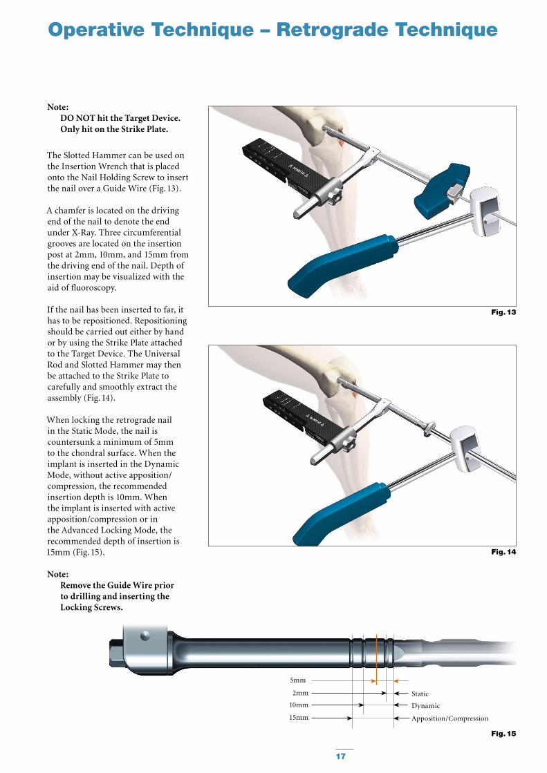
The selected nail is assembled onto the Femoral Target Device (1806-1005) with the Femoral Nail Holding Screw (1806-0165) (Fig. 12). Tighten the Nail Holding Screw with the Universal Joint Socket Wrench (1806-0400) securely so that it does not loosen during nail insertion.
Alternatively, the Fixation Screw Clamp (1806-0273) can be used to fix the Targeting Arm to the Nail Handle. After clamping it on the Targeting Arm the knob will tighten the sleeve to the Targeting Arm.
Caution: Prior to nail insertion please check correct alignment by inserting a drill bit through the assembled Tissue Protection- and Drill Sleeve placed in the required holes of the targeting device (Fig. 12.1).
Upon completion of reaming, the appropriate size nail is ready for in ser tion. Unique to the T2 Femoral Nail, the 3 × 1000mm Ball Tip Guide Wire does not need to be exchanged. The Strike Plate (1806-0150) may be threaded into the hole next to the Nail Holding Screw and the nail is advanced through the entry point past the fracture site to the appropriate level.
Additionally, the 3 × 285mm K-Wire may be inserted through the Targeting Device which identifies the junction of the nail and insertion post which helps determine nail depth through a mini incision using X-Ray (see Fig. 12.2).
Insertion of the 3 × 285mm K-Wire into the lateral cortex may also help to lock the targeting device to the distal femur and prevent rotation of the nail in cases where the Apposition/Compression Locking Mode is utilized.
Caution: Curvature of the nail must match the curvature of the femur.
Nail Insertion
Operative Technique – Retrograde Technique
Note: DO NOT hit the Target Device. Only hit on the Strike Plate.
The Slotted Hammer can be used on the Insertion Wrench that is placed onto the Nail Holding Screw to insert the nail over a Guide Wire (Fig. 13).
A chamfer is located on the driving end of the nail to denote the end under X-Ray. Three circumferential grooves are located on the insertion post at 2mm, 10mm, and 15mm from the driving end of the nail. Depth of insertion may be visualized with the aid of fluoroscopy.
If the nail has been inserted to far, it has to be repositioned. Repositioning should be carried out either by hand or by using the Strike Plate attached to the Target Device. The Universal Rod and Slotted Hammer may then be attached to the Strike Plate to carefully and smoothly extract the assembly (Fig. 14).
When locking the retrograde nail in the Static Mode, the nail is countersunk a minimum of 5mm to the chondral surface. When the implant is inserted in the Dynamic Mode, without active apposition/compression, the recommended insertion depth is 10mm. When the implant is inserted with active apposition/compression or in the Advanced Locking Mode, the recommended depth of insertion is 15mm (Fig. 15).
Note: Remove the Guide Wire prior to drilling and inserting the Locking Screws.
17
Fig. 13
Fig. 14
Operative Technique – Retrograde Technique
Fig. 15
Static
Dynamic
Apposition/Compression15mm
10mm
2mm
5mm
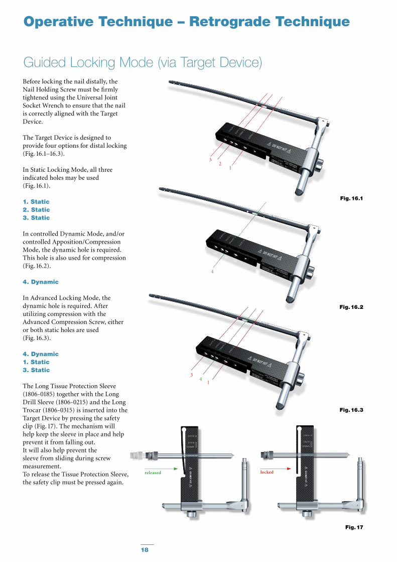
Guided Locking Mode (via Target Device)Before locking the nail distally, the Nail Holding Screw must be firmly tightened using the Universal Joint Socket Wrench to ensure that the nail is correctly aligned with the Target Device.
The Target Device is designed to provide four options for distal locking (Fig. 16.1–16.3).
In Static Locking Mode, all three indicated holes may be used (Fig. 16.1).
1. Static2. Static3. Static
In controlled Dynamic Mode, and/or controlled Apposition/Compression Mode, the dynamic hole is required. This hole is also used for compression (Fig. 16.2).
4. Dynamic
In Advanced Locking Mode, the dynamic hole is required. After utilizing compression with the Advanced Compression Screw, either or both static holes are used (Fig. 16.3).
4. Dynamic1. Static3. Static
The Long Tissue Protection Sleeve (1806-0185) together with the Long Drill Sleeve (1806-0215) and the Long Trocar (1806-0315) is inserted into the Target Device by pressing the safety clip (Fig. 17). The mechanism will help keep the sleeve in place and help prevent it from falling out. It will also help prevent the sleeve from sliding during screw measurement. To release the Tissue Protection Sleeve, the safety clip must be pressed again.
18
Operative Technique – Retrograde Technique
Fig. 16.3
14
3
Fig. 16.2
4
Fig. 16.1
32
1
Fig. 17
lockedreleased
19
Fig. 18
Fig. 19
Operative Technique – Retrograde Technique
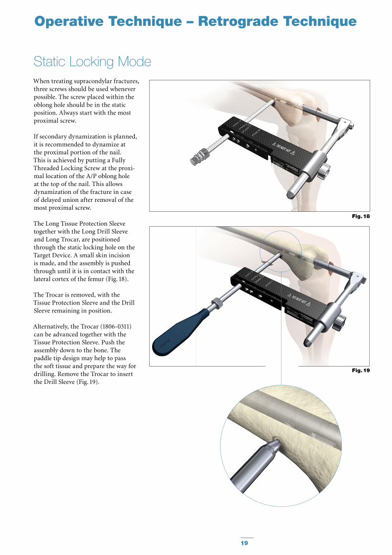
When treating supracondylar frac tures, three screws should be used whenever possible. The screw placed within the oblong hole should be in the static position. Always start with the most proximal screw.
If secondary dynamization is planned, it is recommended to dynamize at the proximal portion of the nail. This is achieved by putting a Fully Threaded Locking Screw at the proxi-mal location of the A/P oblong hole at the top of the nail. This allows dynamization of the fracture in case of delayed union after removal of the most proximal screw.
The Long Tissue Protection Sleeve together with the Long Drill Sleeve and Long Trocar, are positioned through the static locking hole on the Target Device. A small skin incision is made, and the assembly is pushed through until it is in contact with the lateral cortex of the femur (Fig. 18).
The Trocar is removed, with the Tissue Protection Sleeve and the Drill Sleeve remaining in position.
Alternatively, the Trocar (1806-0311) can be advanced together with the Tissue Protection Sleeve. Push the assembly down to the bone. The paddle tip design may help to pass the soft tissue and prepare the way for drilling. Remove the Trocar to insert the Drill Sleeve (Fig. 19).
Static Locking Mode
20
Operative Technique – Retrograde Technique
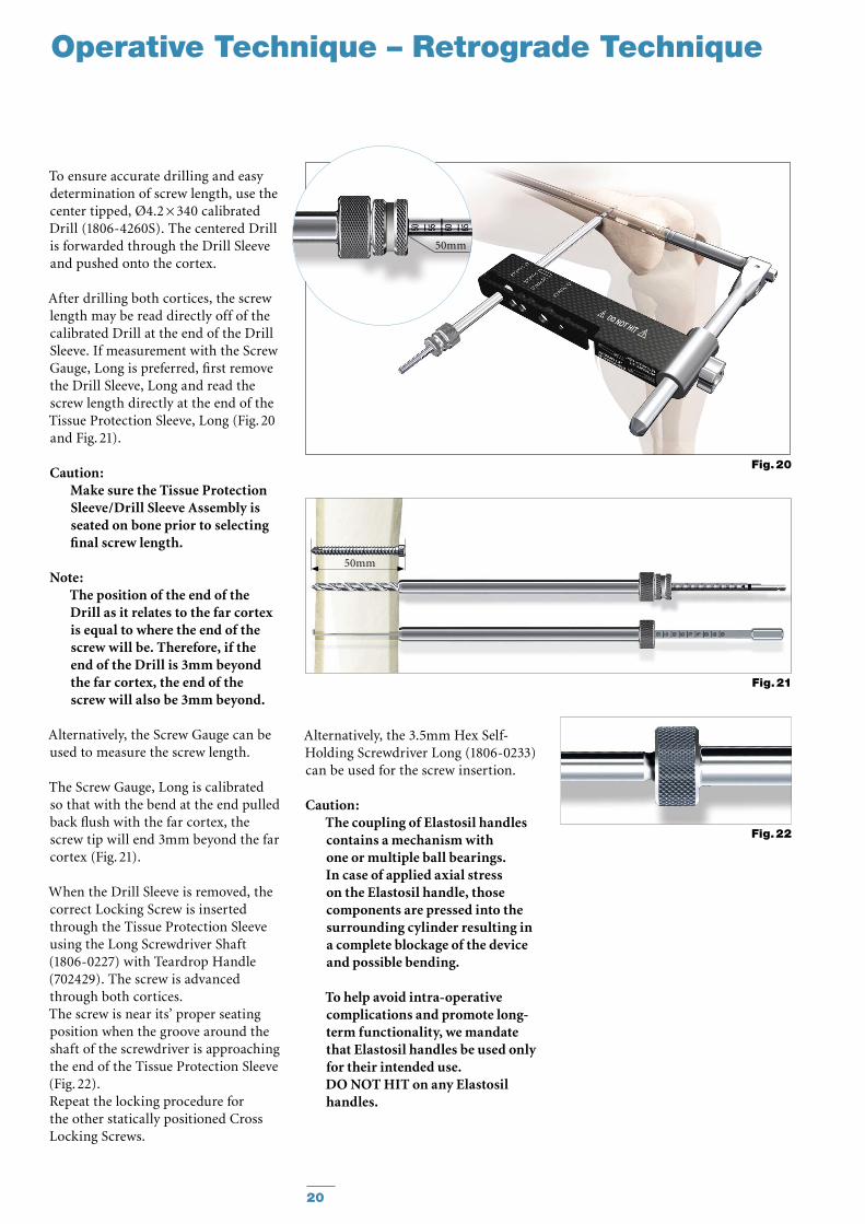
To ensure accurate drilling and easy determination of screw length, use the center tipped, Ø4.2 × 340 calibrated Drill (1806-4260S). The centered Drill is forwarded through the Drill Sleeve and pushed onto the cortex.
After drilling both cortices, the screw length may be read directly off of the calibrated Drill at the end of the Drill Sleeve. If measurement with the Screw Gauge, Long is preferred, first remove the Drill Sleeve, Long and read the screw length directly at the end of the Tissue Protection Sleeve, Long (Fig. 20 and Fig. 21).
Caution: Make sure the Tissue Protection Sleeve/Drill Sleeve Assembly is seated on bone prior to selecting final screw length.
Note: The position of the end of the Drill as it relates to the far cortex is equal to where the end of the screw will be. Therefore, if the end of the Drill is 3mm beyond the far cortex, the end of the screw will also be 3mm beyond.
Alternatively, the Screw Gauge can be used to measure the screw length.
The Screw Gauge, Long is calibrated so that with the bend at the end pulled back flush with the far cortex, the screw tip will end 3mm beyond the far cortex (Fig. 21).
When the Drill Sleeve is removed, the correct Locking Screw is inserted through the Tissue Protection Sleeve using the Long Screwdriver Shaft (1806-0227) with Teardrop Handle (702429). The screw is advanced through both cortices. The screw is near its’ proper seating position when the groove around the shaft of the screwdriver is approach ing the end of the Tissue Protection Sleeve (Fig. 22).Repeat the locking procedure for the other statically positioned Cross Locking Screws.
Alternatively, the 3.5mm Hex Self-Holding Screwdriver Long (1806-0233) can be used for the screw insertion.
Caution: The coupling of Elastosil handles contains a mechanism with one or multiple ball bearings. In case of applied axial stress on the Elastosil handle, those components are pressed into the surrounding cylinder resulting in a complete blockage of the device and possible bending.
To help avoid intra-operative complications and promote long-term functionality, we mandate that Elastosil handles be used only for their intended use. DO NOT HIT on any Elastosil handles.
Fig. 22
Fig. 21
Fig. 20
50mm
50mm
21
Operative Technique – Retrograde Technique
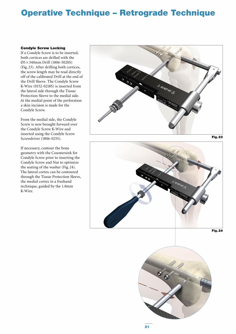
Condyle Screw LockingIf a Condyle Screw is to be inserted, both cortices are drilled with the Ø5 × 340mm Drill (1806-5020S) (Fig. 23). After drilling both cortices, the screw length may be read directly off of the calibrated Drill at the end of the Drill Sleeve. The Condyle Screw K-Wire (0152-0218S) is inserted from the lateral side through the Tissue Protection Sleeve to the medial side. At the medial point of the perforation a skin incision is made for the Condyle Screw.
From the medial side, the Condyle Screw is now brought forward over the Condyle Screw K-Wire and inserted using the Condyle Screw Screwdriver (1806-0255).
If necessary, contour the bone geometry with the Countersink for Condyle Screw prior to inserting the Condyle Screw and Nut to optimize the seating of the washer (Fig. 24).The lateral cortex can be contoured through the Tissue Protection Sleeve, the medial cortex in a freehand technique, guided by the 1.8mm K-Wire.
Fig. 23
Fig. 24
22
Operative Technique – Retrograde Technique
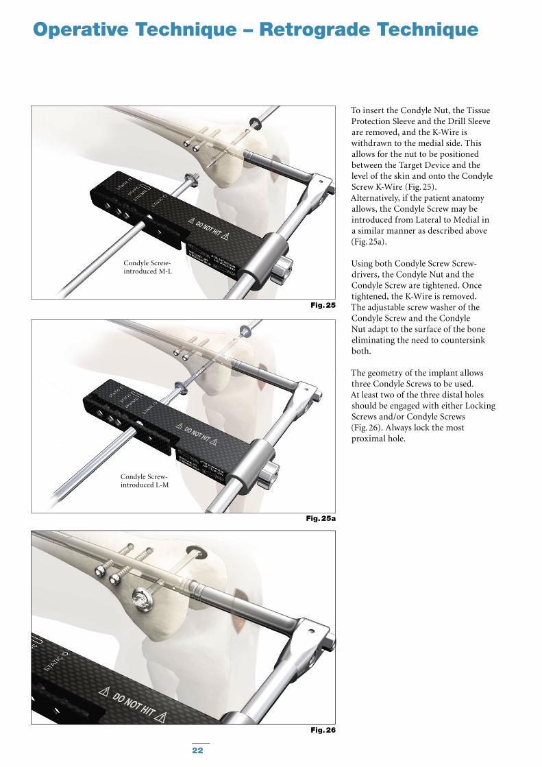
To insert the Condyle Nut, the Tissue Protection Sleeve and the Drill Sleeve are removed, and the K-Wire is withdrawn to the medial side. This allows for the nut to be positioned between the Target Device and the level of the skin and onto the Condyle Screw K-Wire (Fig. 25).Alternatively, if the patient anatomy allows, the Condyle Screw may be introduced from Lateral to Medial in a similar manner as described above (Fig. 25a).
Using both Condyle Screw Screw-drivers, the Condyle Nut and the Condyle Screw are tightened. Once tightened, the K-Wire is removed.The adjustable screw washer of the Condyle Screw and the Condyle Nut adapt to the surface of the bone eliminating the need to countersink both.
The geometry of the implant allows three Condyle Screws to be used. At least two of the three distal holes should be engaged with either Locking Screws and/or Condyle Screws (Fig. 26). Always lock the most proximal hole.
Fig. 26
Fig. 25a
Condyle Screw-introduced L-M
Fig. 25
Condyle Screw-introduced M-L
23
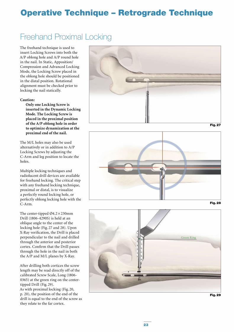
The freehand technique is used to insert Locking Screws into both the A/P oblong hole and A/P round hole in the nail. In Static, Apposition/Compression and Advanced Locking Mode, the Locking Screw placed in the oblong hole should be positioned in the distal position. Rotational alignment must be checked prior to locking the nail statically.
Caution: Only one Locking Screw is inserted in the Dynamic Locking Mode. The Locking Screw is placed in the proximal position of the A/P oblong hole in order to optimize dynamization at the proximal end of the nail.
The M/L holes may also be used alternatively or in addition to A/P Locking Screws by adjusting the C-Arm and leg position to locate the holes.
Multiple locking techniques and radiolucent drill devices are available for freehand locking. The critical step with any freehand locking technique, proximal or distal, is to visualize a perfectly round locking hole, or perfectly oblong locking hole with the C-Arm.
The center-tipped Ø4.2 × 230mm Drill (1806-4290S) is held at an oblique angle to the center of the locking hole (Fig. 27 and 28). Upon X-Ray verification, the Drill is placed perpendicular to the nail and drilled through the anterior and posterior cortex. Confirm that the Drill passes through the hole in the nail in both the A/P and M/L planes by X-Ray.
After drilling both cortices the screw length may be read directly off of the calibrated Screw Scale, Long (1806-0365) at the green ring on the center-tipped Drill (Fig. 29).As with proximal locking (Fig. 20, p. 20), the position of the end of the drill is equal to the end of the screw as they relate to the far cortex.
Freehand Proximal Locking
Fig. 28
Fig. 27
Green Ring
Fig. 29
Operative Technique – Retrograde Technique
24
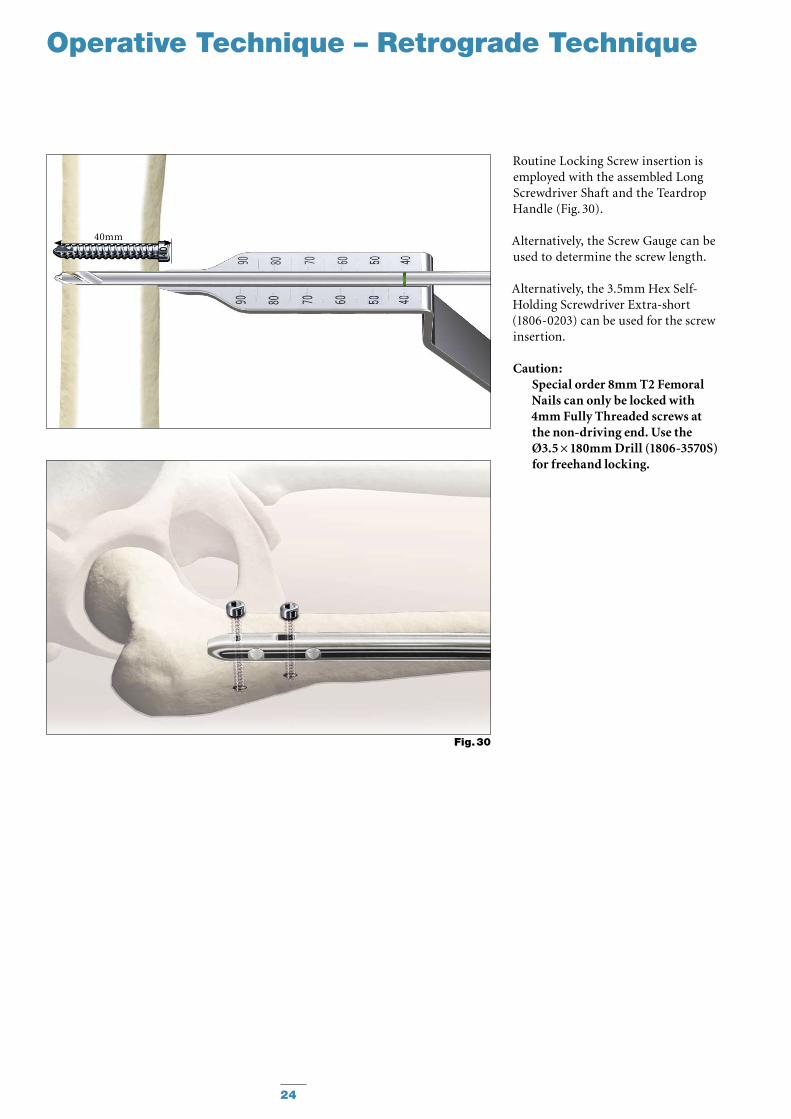
Routine Locking Screw insertion is employed with the assembled Long Screwdriver Shaft and the Teardrop Handle (Fig. 30).
Alternatively, the Screw Gauge can be used to determine the screw length.
Alternatively, the 3.5mm Hex Self-Holding Screwdriver Extra-short (1806-0203) can be used for the screw insertion.
Caution: Special order 8mm T2 Femoral Nails can only be locked with 4mm Fully Threaded screws at the non-driving end. Use the Ø3.5 × 180mm Drill (1806-3570S) for freehand locking.
Operative Technique – Retrograde Technique
40mm
Fig. 30
25
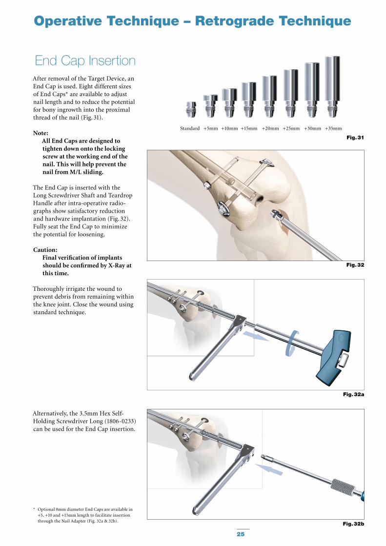
After removal of the Target Device, an End Cap is used. Eight different sizes of End Caps* are available to adjust nail length and to reduce the potential for bony ingrowth into the proximal thread of the nail (Fig. 31).
Note: All End Caps are designed to tighten down onto the locking screw at the working end of the nail. This will help prevent the nail from M/L sliding.
The End Cap is inserted with the Long Screwdriver Shaft and Teardrop Handle after intra-operative radio-graphs show satisfactory reduction and hardware implantation (Fig. 32). Fully seat the End Cap to minimize the potential for loosening.
Caution: Final verification of implants should be confirmed by X-Ray at this time.
Thoroughly irrigate the wound to prevent debris from remaining within the knee joint. Close the wound using standard technique.
Alternatively, the 3.5mm Hex Self-Holding Screwdriver Long (1806-0233) can be used for the End Cap insertion.
End Cap Insertion
Fig. 32
Fig. 32b
Fig. 31
Standard +5mm +10mm +15mm +20mm +25mm +30mm +35mm
Operative Technique – Retrograde Technique
Fig. 32a
* Optional 8mm diameter End Caps are available in +5, +10 and +15mm length to facilitate insertion through the Nail Adapter (Fig. 32a & 32b).
26
Operative Technique – Retrograde Technique
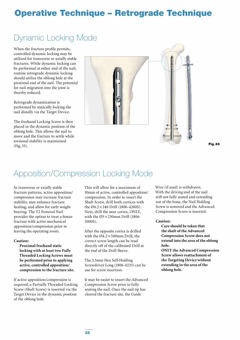
When the fracture profile permits, controlled dynamic locking may be utilized for transverse or axially stable fractures. While dynamic locking can be performed at either end of the nail, routine retrograde dynamic locking should utilize the oblong hole at the proximal end of the nail. The potential for nail migration into the joint is thereby reduced.
Retrograde dynamization is performed by statically locking the nail distally via the Target Device.
The freehand Locking Screw is then placed in the dynamic position of the oblong hole. This allows the nail to move and the fracture to settle while torsional stability is maintained (Fig. 33).
Dynamic Locking Mode
Fig. 33
In transverse or axially stable fracture patterns, active apposition/compression may increase fracture stability, may enhance fracture healing, and allow for early weight bearing. The T2 Femoral Nail provides the option to treat a femur fracture with active mechanical apposition/compression prior to leaving the operating room.
Caution: Proximal freehand static locking with at least two Fully Threaded Locking Screws must be performed prior to applying active, controlled apposition/compression to the fracture site.
If active apposition/compression is required, a Partially Threaded Locking Screw (Shaft Screw) is inserted via the Target Device in the dynamic position of the oblong hole.
Apposition/Compression Locking Mode
This will allow for a maximum of 10mm of active, controlled apposition/compression. In order to insert the Shaft Screw, drill both cortices with the Ø4.2 × 340 Drill (1806-4260S). Next, drill the near cortex, ONLY, with the Ø5 × 230mm Drill (1806-5000S).
After the opposite cortex is drilled with the Ø4.2 × 340mm Drill, the correct screw length can be read directly off of the calibrated Drill at the end of the Drill Sleeve.
The 3.5mm Hex Self-Holding Screwdriver Long (1806-0233) can be use for screw insertion. It may be easier to insert the Advanced Compression Screw prior to fully seating the nail. Once the nail tip has cleared the fracture site, the Guide
Wire (if used) is withdrawn. With the driving end of the nail still not fully seated and extending out of the bone, the Nail Holding Screw is removed and the Advanced Compression Screw is inserted.
Caution: Care should be taken that the shaft of the Advanced Compression Screw does not extend into the area of the oblong hole. ONLY the Advanced Compression Screw allows reattachment of the Targeting Device without extending in the area of the oblong hole.
27
Caution: In order to prevent damage during drilling and insertion of the most proximal locking screw, the Advanced Compression Screw has to be placed between the oblong hole and the most proximal locking hole.
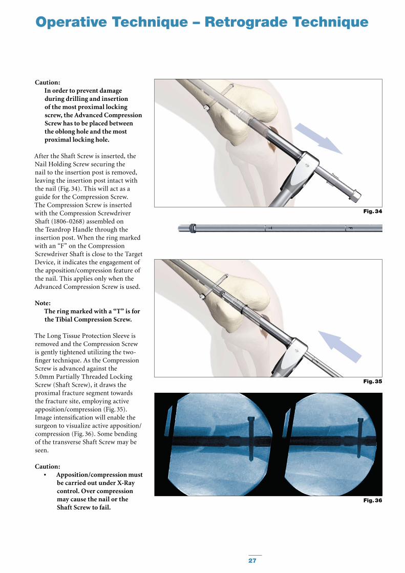
After the Shaft Screw is inserted, the Nail Holding Screw securing the nail to the insertion post is removed, leaving the insertion post intact with the nail (Fig. 34). This will act as a guide for the Compression Screw. The Compres sion Screw is inserted with the Compression Screwdriver Shaft (1806-0268) assembled on the Teardrop Handle through the insertion post. When the ring marked with an “F” on the Com pression Screwdriver Shaft is close to the Target Device, it indicates the engagement of the apposition/compression feature of the nail. This applies only when the Advanced Compression Screw is used.
Note: The ring marked with a “T” is for the Tibial Compression Screw.
The Long Tissue Protection Sleeve is removed and the Compression Screw is gently tightened utilizing the two-finger technique. As the Compression Screw is advanced against the 5.0mm Partially Threaded Locking Screw (Shaft Screw), it draws the proximal fracture segment towards the fracture site, employing active apposition/compression (Fig. 35). Image intensification will enable the surgeon to visualize active apposition/compression (Fig. 36). Some bending of the transverse Shaft Screw may be seen.
Caution: Apposition/compression must •be carried out under X-Ray control. Over compression may cause the nail or the Shaft Screw to fail.
Operative Technique – Retrograde Technique
Fig. 36
Fig. 34
Fig. 35
28
When compressing the nail, •the implant must be inserted a safe distance from the entry point to accommodate for the 10mm of active compression. The three grooves on the insertion post help attain accurate insertion depth of the implant.
Operative Technique – Retrograde Technique
Compression Screws are available in different lengths. A short Advanced Compression Screw to enable the Advanced Locking Mode and longer Compression Screws from Standard to +15mm offer an improved fit. An End Cap can only be inserted when using the Advanced Compression Screw or when not using compression.
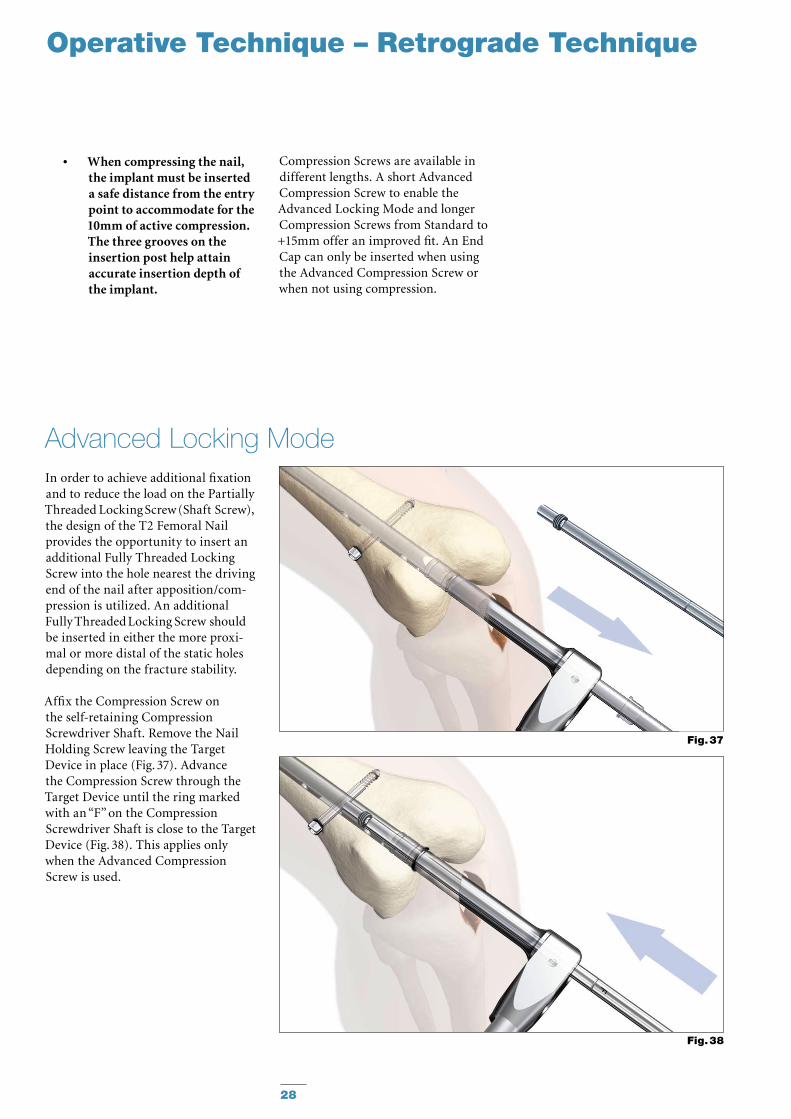
In order to achieve additional fixation and to reduce the load on the Partially Threaded Locking Screw (Shaft Screw), the design of the T2 Femoral Nail provides the opportunity to insert an additional Fully Threaded Lock ing Screw into the hole nearest the driving end of the nail after apposition/com-pression is utilized. An additional Fully Threaded Locking Screw should be inserted in either the more proxi-mal or more distal of the static holes depending on the fracture stability.
Affix the Compression Screw on the self-retaining Compression Screwdriver Shaft. Remove the Nail Holding Screw leaving the Target Device in place (Fig. 37). Advance the Compression Screw through the Target Device until the ring marked with an “F” on the Compression Screwdriver Shaft is close to the Target Device (Fig. 38). This applies only when the Advanced Compression Screw is used.
Advanced Locking Mode
Fig. 38
Fig. 37
29
Operative Technique – Retrograde Technique
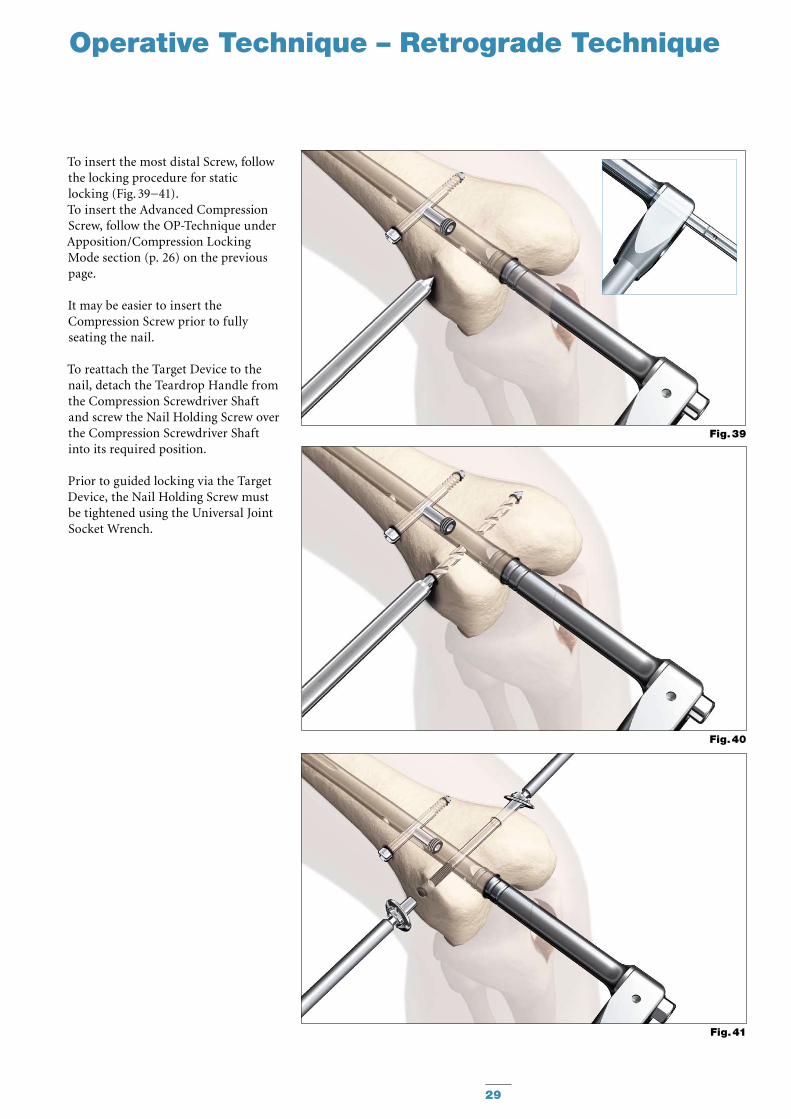
To insert the most distal Screw, follow the locking procedure for static locking (Fig. 39−41).To insert the Advanced Compression Screw, follow the OP-Tech nique under Apposition/Compression Locking Mode section (p. 26) on the previous page.
It may be easier to insert the Compression Screw prior to fully seating the nail.
To reattach the Target Device to the nail, detach the Teardrop Handle from the Compression Screwdriver Shaft and screw the Nail Holding Screw over the Compression Screwdriver Shaft into its required position.
Prior to guided locking via the Target Device, the Nail Holding Screw must be tightened using the Universal Joint Socket Wrench.
Fig. 41
Fig. 40
Fig. 39
30
Operative Technique – Retrograde Technique
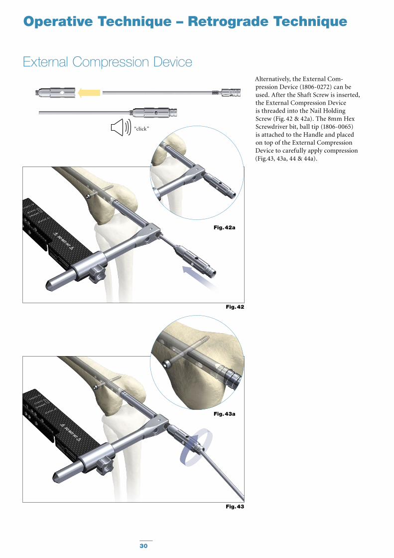
External Compression DeviceAlternatively, the External Com-pression Device (1806-0272) can be used. After the Shaft Screw is inserted, the External Compression Device is threaded into the Nail Holding Screw (Fig. 42 & 42a). The 8mm Hex Screwdriver bit, ball tip (1806-0065) is attached to the Handle and placed on top of the External Compression Device to carefully apply compression (Fig.43, 43a, 44 & 44a).
Fig. 42a
Fig. 43a
Fig. 42
Fig. 43
“click”
31
Operative Technique – Retrograde Technique
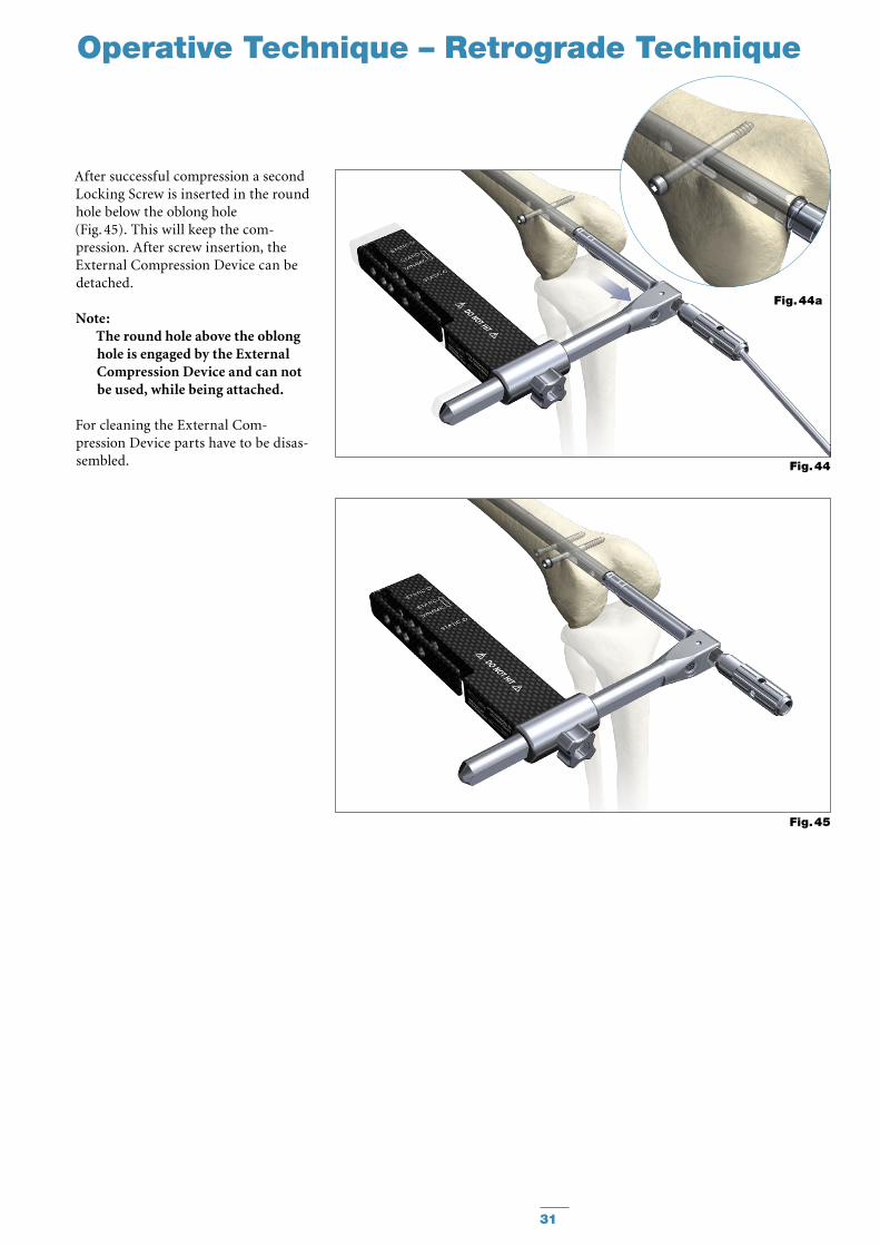
After successful compression a second Locking Screw is inserted in the round hole below the oblong hole (Fig. 45). This will keep the com-pression. After screw insertion, the External Compression Device can be detached.
Note: The round hole above the oblong hole is engaged by the External Compression Device and can not be used, while being attached.
For cleaning the External Com-pression Device parts have to be disas-sembled.
Fig. 44a
Fig. 44
Fig. 45
32
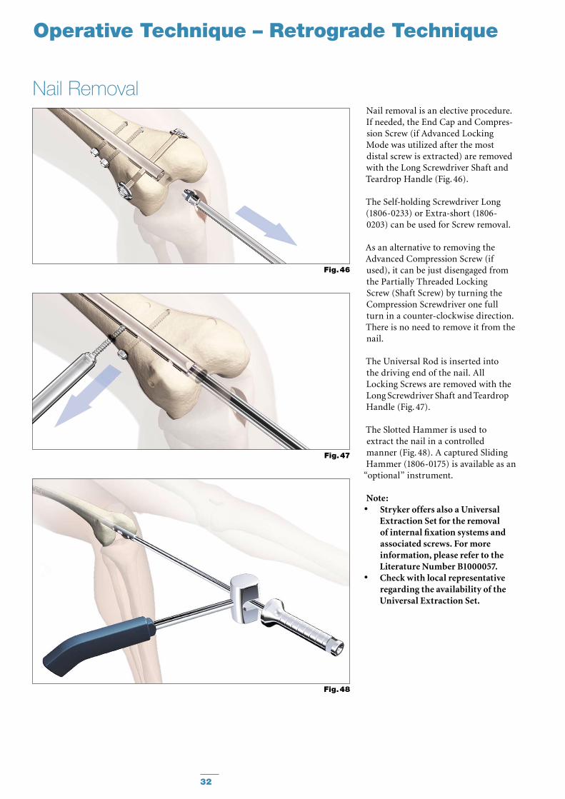
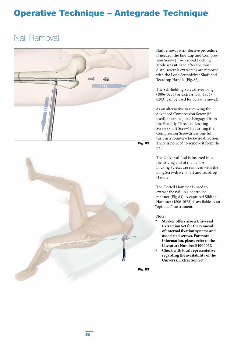
Nail removal is an elective procedure. If needed, the End Cap and Compres-sion Screw (if Advanced Locking Mode was utilized after the most distal screw is extracted) are removed with the Long Screwdriver Shaft and Teardrop Handle (Fig. 46).
The Self-holding Screwdriver Long (1806-0233) or Extra-short (1806-0203) can be used for Screw removal.
As an alternative to removing the Advanced Compression Screw (if used), it can be just disengaged from the Partially Threaded Locking Screw (Shaft Screw) by turning the Compression Screwdriver one full turn in a counter-clockwise direction. There is no need to remove it from the nail.
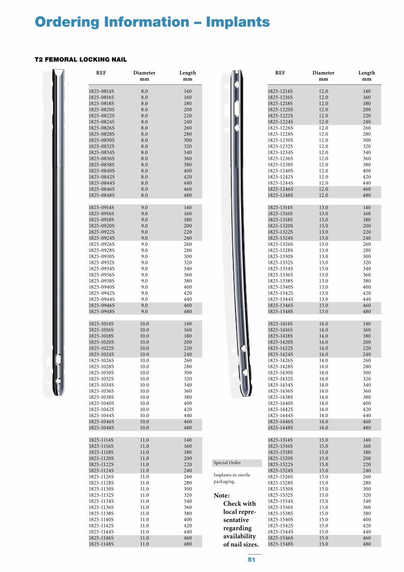
The Universal Rod is inserted into the driving end of the nail. All Locking Screws are removed with the Long Screwdriver Shaft and Teardrop Handle (Fig. 47).
The Slotted Hammer is used to extract the nail in a controlled manner (Fig. 48). A captured Sliding Hammer (1806-0175) is available as an
“optional” instrument.
Note: Stryker offers also a Universal •Extraction Set for the removal of internal fixation systems and associated screws. For more information, please refer to the Literature Number B1000057.Check with local representative •regarding the availability of the Universal Extraction Set.
Nail Removal
Fig. 46
Fig. 47
Fig. 48
Operative Technique – Retrograde Technique
33
Operative Technique – Antegrade Technique
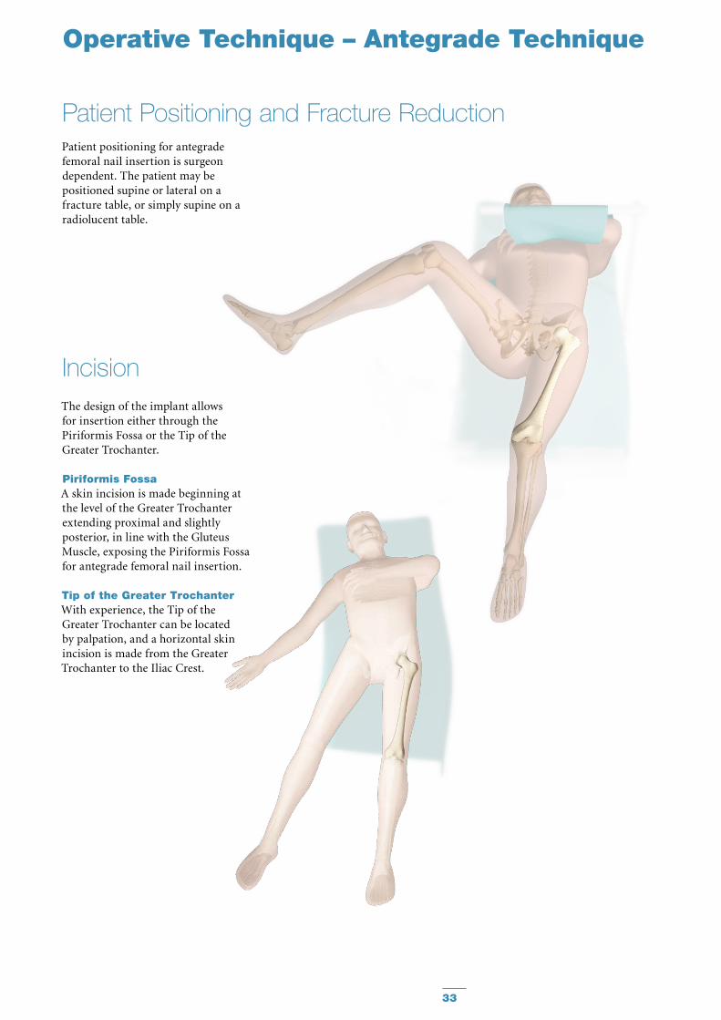
Patient positioning for antegrade femoral nail insertion is surgeon dependent. The patient may be positioned supine or lateral on a fracture table, or simply supine on a radiolucent table.
The design of the implant allows for insertion either through the Piriformis Fossa or the Tip of the Greater Trochanter.
Piriformis FossaA skin incision is made beginning at the level of the Greater Tro chanter extending proximal and slightly posterior, in line with the Gluteus Muscle, exposing the Piriformis Fossa for antegrade femoral nail insertion.
Tip of the Greater TrochanterWith experience, the Tip of the Greater Trochanter can be located by palpation, and a horizontal skin incision is made from the Greater Trochanter to the Iliac Crest.
Incision
Patient Positioning and Fracture Reduction
34
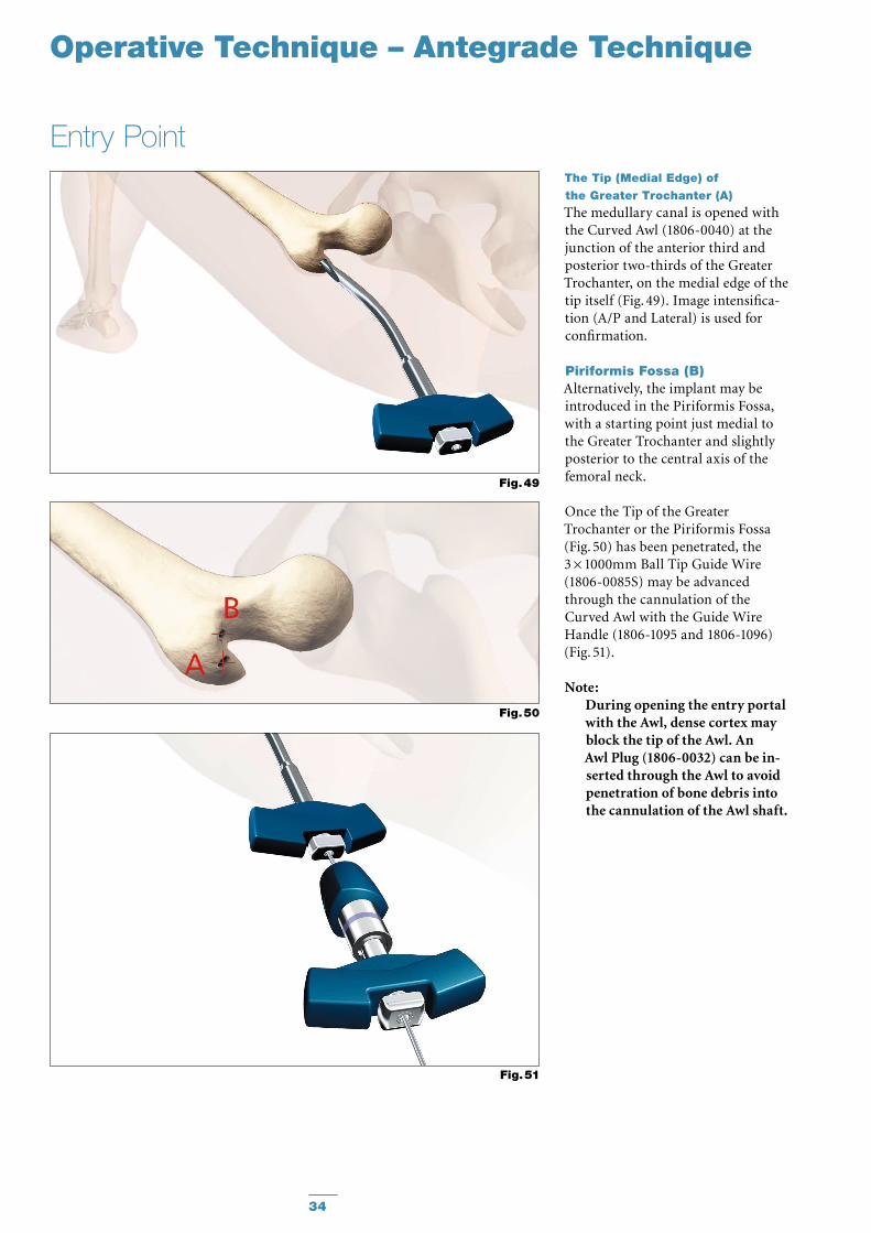
The Tip (Medial Edge) of
the Greater Trochanter (A)
The medullary canal is opened with the Curved Awl (1806-0040) at the junction of the anterior third and pos terior two-thirds of the Greater Trochanter, on the medial edge of the tip itself (Fig. 49). Image intensifica-tion (A/P and Lateral) is used for confirmation.
Piriformis Fossa (B)Alternatively, the implant may be introduced in the Piriformis Fossa, with a starting point just medial to the Greater Trochanter and slightly posterior to the central axis of the femoral neck.
Once the Tip of the Greater Trochanter or the Piriformis Fossa (Fig. 50) has been penetrated, the 3 × 1000mm Ball Tip Guide Wire (1806-0085S) may be advanced through the cannulation of the Curved Awl with the Guide Wire Handle (1806-1095 and 1806-1096) (Fig. 51).
Note:During opening the entry portal with the Awl, dense cortex may block the tip of the Awl. An Awl Plug (1806-0032) can be in- serted through the Awl to avoid penetration of bone debris into the cannulation of the Awl shaft.
Entry Point
Fig. 49
Fig. 51
Fig. 50
Operative Technique – Antegrade Technique
35
Operative Technique – Antegrade Technique
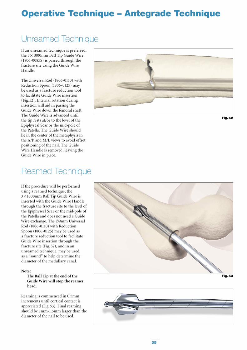
If an unreamed technique is pre ferred, the 3 × 1000mm Ball Tip Guide Wire (1806-0085S) is passed through the fracture site using the Guide Wire Handle.
The Universal Rod (1806-0110) with Reduction Spoon (1806-0125) may be used as a fracture reduction tool to facilitate Guide Wire insertion (Fig. 52). Internal rotation during insertion will aid in passing the Guide Wire down the femoral shaft. The Guide Wire is advanced until the tip rests at/or to the level of the Epiphyseal Scar or the mid-pole of the Patella. The Guide Wire should lie in the center of the metaphysis in the A/P and M/L views to avoid offset positioning of the nail. The Guide Wire Handle is removed, leaving the Guide Wire in place.
Unreamed Technique
Fig. 52
Fig. 53
If the procedure will be performed using a reamed technique, the 3 × 1000mm Ball Tip Guide Wire is inserted with the Guide Wire Handle through the fracture site to the level of the Epiphyseal Scar or the mid-pole of the Patella and does not need a Guide Wire exchange. The Ø9mm Universal Rod (1806-0110) with Reduction Spoon (1806-0125) may be used as a fracture reduction tool to facilitate Guide Wire insertion through the fracture site (Fig. 52), and in an unreamed technique, may be used as a “sound” to help determine the diameter of the medullary canal.
Note: The Ball Tip at the end of the Guide Wire will stop the reamer head.
Reaming is commenced in 0.5mm increments until cortical contact is appreciated (Fig. 53). Final reaming should be 1mm-1.5mm larger than the diam eter of the nail to be used.
Reamed Technique
36
Operative Technique – Antegrade Technique
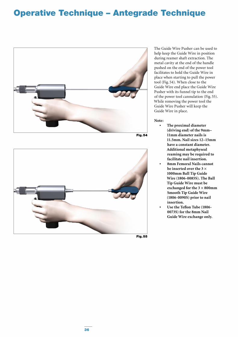
The Guide Wire Pusher can be used to help keep the Guide Wire in position during reamer shaft extraction. The metal cavity at the end of the handle pushed on the end of the power tool facilitates to hold the Guide Wire in place when starting to pull the power tool (Fig. 54). When close to the Guide Wire end place the Guide Wire Pusher with its funnel tip to the end of the power tool cannulation (Fig. 55). While removing the power tool the Guide Wire Pusher will keep the Guide Wire in place.
Note: The proximal diameter •(driving end) of the 9mm–11mm diameter nails is 11.5mm. Nail sizes 12–15mm have a constant diameter. Additional metaphyseal reaming may be required to facilitate nail insertion.8mm Femoral Nails cannot •be inserted over the 3 × 1000mm Ball Tip Guide Wire (1806-0085S). The Ball Tip Guide Wire must be exchanged for the 3 × 800mm Smooth Tip Guide Wire (1806-0090S) prior to nail insertion.Use the Teflon Tube (1806- •0073S) for the 8mm Nail Guide Wire exchange only.
Fig. 54
Fig. 55
37
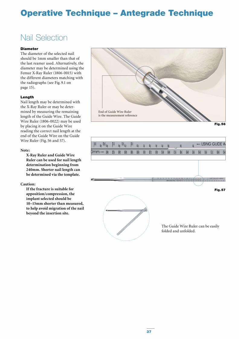
End of Guide Wire Ruleris the measurement reference
Fig. 56
Operative Technique – Antegrade Technique
The Guide Wire Ruler can be easily folded and unfolded.
Fig. 57
DiameterThe diameter of the selected nail should be 1mm smaller than that of the last reamer used. Alternatively, the diameter may be determined using the Femur X-Ray Ruler (1806-0015) with the different diameters matching with the radiographs (see Fig. 9.1 on page 15).
LengthNail length may be determined with the X-Ray Ruler or may be deter-mined by measuring the remaining length of the Guide Wire. The Guide Wire Ruler (1806-0022) may be used by placing it on the Guide Wire reading the correct nail length at the end of the Guide Wire on the Guide Wire Ruler (Fig. 56 and 57).
Note: X-Ray Ruler and Guide Wire Ruler can be used for nail length determination beginning from 240mm. Shorter nail length can be determined via the template.
Caution: If the fracture is suitable for apposi tion/compression, the implant se lect ed should be 10–15mm shorter than measured, to help avoid migration of the nail beyond the insertion site.
Nail Selection
38
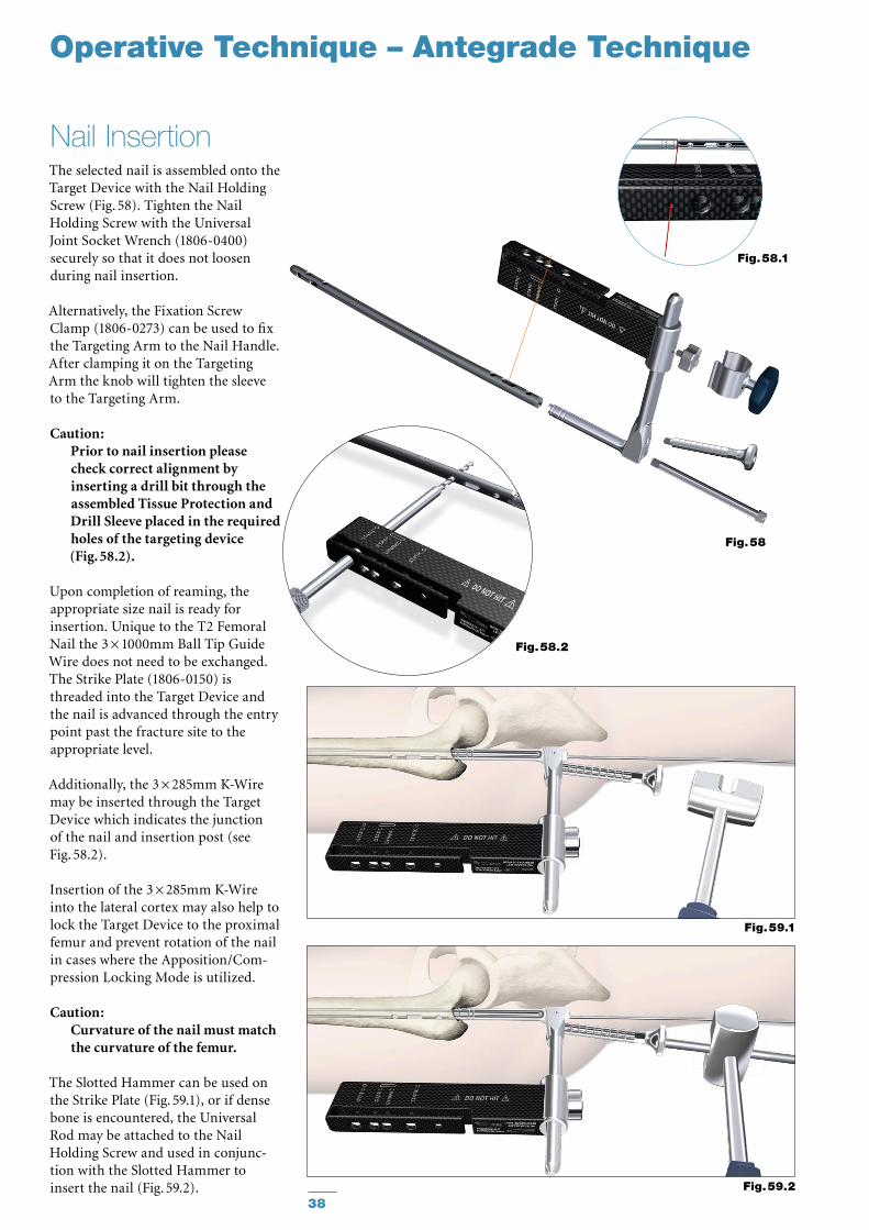
The selected nail is assembled onto the Target Device with the Nail Holding Screw (Fig. 58). Tighten the Nail Holding Screw with the Universal Joint Socket Wrench (1806-0400) securely so that it does not loosen during nail insertion.
Alternatively, the Fixation Screw Clamp (1806-0273) can be used to fix the Targeting Arm to the Nail Handle. After clamping it on the Targeting Arm the knob will tighten the sleeve to the Targeting Arm.
Caution: Prior to nail insertion please check correct alignment by inserting a drill bit through the assembled Tissue Protection and Drill Sleeve placed in the required holes of the targeting device (Fig. 58.2).
Upon completion of reaming, the appropriate size nail is ready for insertion. Unique to the T2 Femoral Nail the 3 × 1000mm Ball Tip Guide Wire does not need to be exchanged. The Strike Plate (1806-0150) is threaded into the Target Device and the nail is advanced through the entry point past the fracture site to the appropriate level.
Additionally, the 3 × 285mm K-Wire may be inserted through the Target Device which indicates the junc tion of the nail and insertion post (see Fig. 58.2).
Insertion of the 3 × 285mm K-Wire into the lateral cortex may also help to lock the Target Device to the proximal femur and prevent rotation of the nail in cases where the Apposition/Com-pression Locking Mode is utilized.
Caution: Curvature of the nail must match the curvature of the femur.
The Slotted Hammer can be used on the Strike Plate (Fig. 59.1), or if dense bone is encountered, the Universal Rod may be attached to the Nail Holding Screw and used in conjunc-tion with the Slotted Hammer to insert the nail (Fig. 59.2).
Nail Insertion
Fig. 59.1
Fig. 59.2
Fig. 58.1
Fig. 58
Fig. 58.2
Operative Technique – Antegrade Technique
K-Wire
39
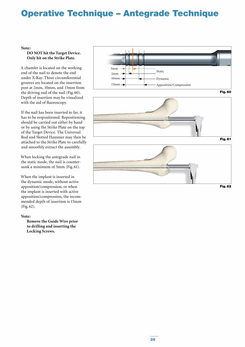
Note: DO NOT hit the Target Device. Only hit on the Strike Plate.
A chamfer is located on the working end of the nail to denote the end under X-Ray. Three circumferential grooves are located on the insertion post at 2mm, 10mm, and 15mm from the driving end of the nail (Fig. 60). Depth of insertion may be visualized with the aid of fluoroscopy.
If the nail has been inserted to far, it has to be respositioned. Repositioning should be carried out either by hand or by using the Strike Plate on the top of the Target Device. The Universal Rod and Slotted Hammer may then be attached to the Strike Plate to carefully and smoothly extract the assembly.
When locking the antegrade nail in the static mode, the nail is counter-sunk a minimum of 5mm (Fig. 61).
When the implant is inserted in the dynamic mode, without active apposition/compression, or when the implant is inserted with active apposition/compression, the recom-mended depth of insertion is 15mm (Fig. 62).
Note: Remove the Guide Wire prior to drilling and inserting the Locking Screws.
Fig. 61
Fig. 62
Fig. 60
10mm
2mm
15mm
Static
Dynamic
Apposition/Compression
5mm
Operative Technique – Antegrade Technique
40
Guided Locking Mode (via Target Device)
Fig. 63
Operative Technique – Antegrade Technique
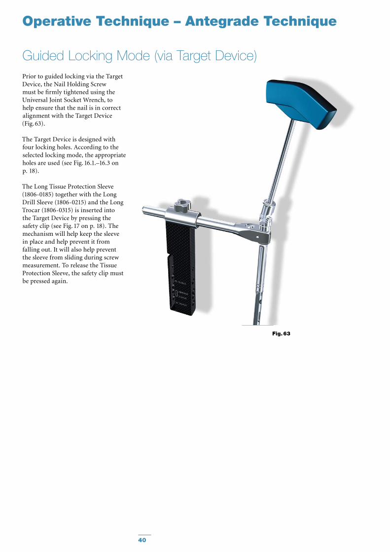
Prior to guided locking via the Target Device, the Nail Holding Screw must be firmly tightened using the Universal Joint Socket Wrench, to help ensure that the nail is in correct alignment with the Target Device (Fig. 63).
The Target Device is designed with four locking holes. According to the selected locking mode, the appropri ate holes are used (see Fig. 16.1.–16.3 on p. 18).
The Long Tissue Protection Sleeve (1806-0185) together with the Long Drill Sleeve (1806-0215) and the Long Trocar (1806-0315) is inserted into the Target Device by pressing the safety clip (see Fig. 17 on p. 18). The mechanism will help keep the sleeve in place and help prevent it from falling out. It will also help prevent the sleeve from sliding during screw measurement. To release the Tissue Protection Sleeve, the safety clip must be pressed again.
41
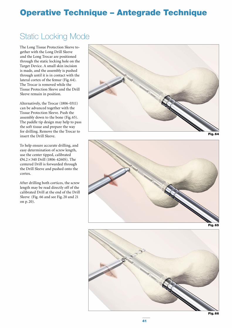
The Long Tissue Protection Sleeve to -gether with the Long Drill Sleeve and the Long Trocar are positioned through the static locking hole on the Target Device. A small skin incision is made, and the assembly is pushed through until it is in contact with the lateral cortex of the femur (Fig. 64). The Trocar is removed while the Tissue Protection Sleeve and the Drill Sleeve remain in position.
Alternatively, the Trocar (1806-0311) can be advanced together with the Tissue Protection Sleeve. Push the assembly down to the bone (Fig. 65). The paddle tip design may help to pass the soft tissue and prepare the way for drilling. Remove the the Trocar to insert the Drill Sleeve.
To help ensure accurate drilling, and easy determination of screw length, use the center tipped, calibrated Ø4.2 × 340 Drill (1806-4260S). The centered Drill is forwarded through the Drill Sleeve and pushed onto the cortex.
After drilling both cortices, the screw length may be read directly off of the calibrated Drill at the end of the Drill Sleeve (Fig. 66 and see Fig. 20 and 21 on p. 20).
Static Locking Mode
Fig. 64
Fig. 65
Fig. 66
Operative Technique – Antegrade Technique
42
Operative Technique – Antegrade Technique
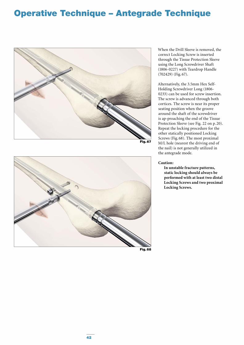
When the Drill Sleeve is removed, the correct Locking Screw is inserted through the Tissue Protection Sleeve using the Long Screwdriver Shaft (1806-0227) with Teardrop Handle (702429) (Fig. 67).
Alternatively, the 3.5mm Hex Self-Holding Screwdriver Long (1806-0233) can be used for screw insertion. The screw is ad vanced through both cortices. The screw is near its proper seating position when the groove around the shaft of the screwdriver is ap -proaching the end of the Tissue Pro tection Sleeve (see Fig. 22 on p. 20).Repeat the locking procedure for the other statically positioned Locking Screws (Fig. 68). The most proximal M/L hole (nearest the driving end of the nail) is not generally utilized in the antegrade mode.
Caution: In unstable fracture patterns, static locking should always be per formed with at least two distal Locking Screws and two proximal Locking Screws.
Fig. 68
Fig. 67
43
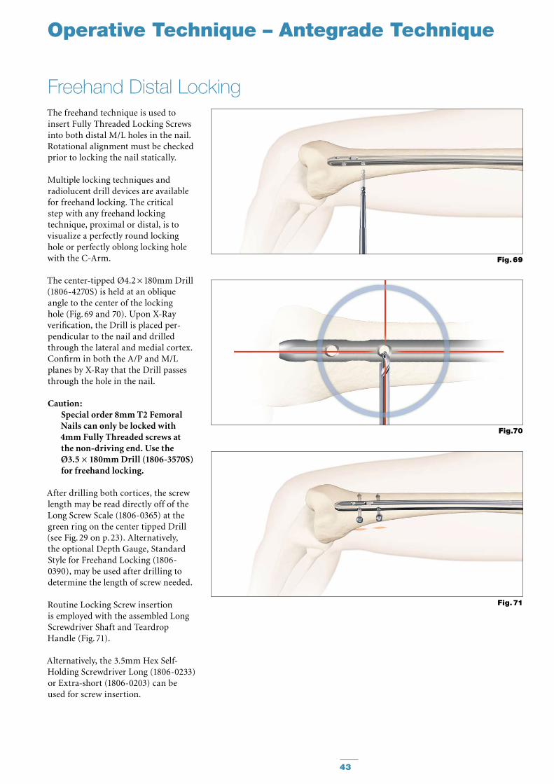
The freehand technique is used to insert Fully Threaded Locking Screws into both distal M/L holes in the nail. Rotational alignment must be checked prior to locking the nail statically.
Multiple locking techniques and radiolucent drill devices are available for freehand locking. The critical step with any freehand locking tech nique, proximal or distal, is to visualize a perfectly round locking hole or perfectly oblong locking hole with the C-Arm.
The center-tipped Ø4.2 × 180mm Drill (1806-4270S) is held at an oblique angle to the center of the locking hole (Fig. 69 and 70). Upon X-Ray verification, the Drill is placed per-pendicular to the nail and drilled through the lateral and medial cortex. Confirm in both the A/P and M/L planes by X-Ray that the Drill passes through the hole in the nail.
Caution: Special order 8mm T2 Femoral Nails can only be locked with 4mm Fully Threaded screws at the non-driving end. Use the Ø3.5 × 180mm Drill (1806-3570S) for freehand locking.
After drilling both cortices, the screw length may be read directly off of the Long Screw Scale (1806-0365) at the green ring on the center tipped Drill (see Fig. 29 on p. 23). Alternatively, the optional Depth Gauge, Standard Style for Freehand Locking (1806-0390), may be used after drilling to determine the length of screw needed.
Routine Locking Screw insertion is employed with the assembled Long Screwdriver Shaft and Teardrop Handle (Fig. 71).
Alternatively, the 3.5mm Hex Self-Holding Screwdriver Long (1806-0233) or Extra-short (1806-0203) can be used for screw insertion.
Freehand Distal Locking
Fig. 69
Fig.70
Fig. 71
Operative Technique – Antegrade Technique
44
* Optional 8mm diameter End Caps are available in +5, +10 and +15mm length to facilitate insertion through the Nail Adapter (Fig. 61a & 61b).
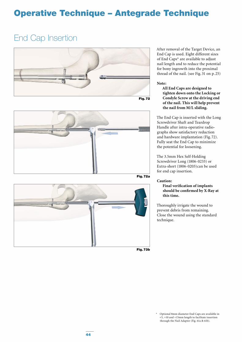
End Cap InsertionAfter removal of the Target Device, an End Cap is used. Eight different sizes of End Caps* are available to adjust nail length and to reduce the potential for bony ingrowth into the proximal thread of the nail. (see Fig. 31 on p. 25)
Note: All End Caps are designed to tighten down onto the Locking or Condyle Screw at the driving end of the nail. This will help prevent the nail from M/L sliding.
The End Cap is inserted with the Long Screwdriver Shaft and Teardrop Han dle after intra-operative radio-graphs show satisfactory reduction and hard ware implantation (Fig. 72). Fully seat the End Cap to minimize the potential for loosening.
The 3.5mm Hex Self-Holding Screwdriver Long (1806-0233) or Extra-short (1806-0203)can be used for end cap insertion.
Caution: Final verification of implants should be confirmed by X-Ray at this time.
Thoroughly irrigate the wound to prevent debris from remaining. Close the wound using the standard technique.
Operative Technique – Antegrade Technique
Fig. 72a
Fig. 73b
Fig. 72
45
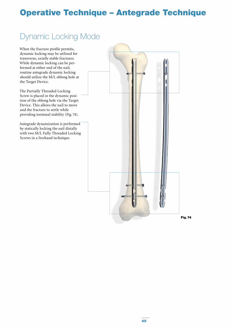
When the fracture profile permits, dynamic locking may be utilized for transverse, axially stable fractures. While dynamic locking can be per-formed at either end of the nail, routine antegrade dynamic locking should utilize the M/L oblong hole at the Target Device.
The Partially Threaded Locking Screw is placed in the dynamic posi -tion of the oblong hole via the Target Device. This allows the nail to move and the fracture to settle while provid ing torsional stability (Fig. 74).
Antegrade dynamization is performed by statically locking the nail distally with two M/L Fully Threaded Locking Screws in a freehand technique.
Dynamic Locking Mode
Operative Technique – Antegrade Technique
Fig. 74
46
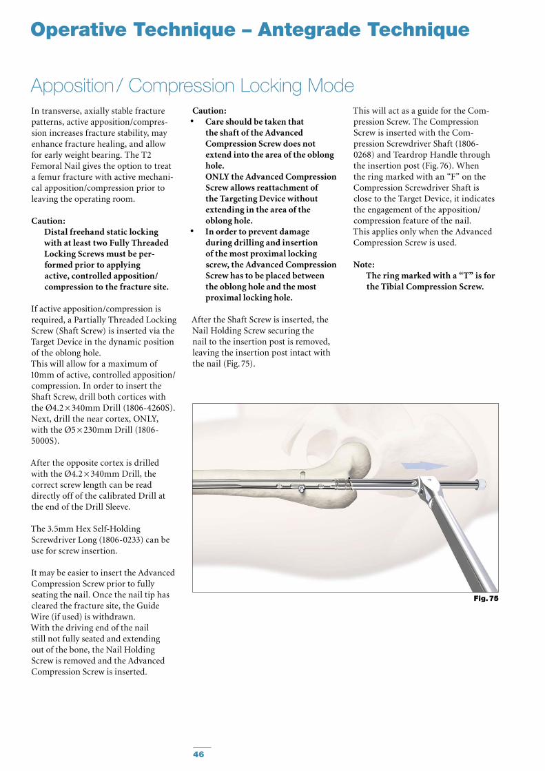
In transverse, axially stable fracture patterns, active apposition/compres-sion increases fracture stability, may enhance fracture healing, and allow for early weight bearing. The T2 Femoral Nail gives the option to treat a femur fracture with active mechani-cal apposition/compression prior to leaving the operating room.
Caution: Distal freehand static locking with at least two Fully Threaded Locking Screws must be per-formed prior to applying active, control led apposition/compression to the fracture site.
If active apposition/compression is required, a Partially Threaded Locking Screw (Shaft Screw) is in serted via the Target Device in the dynamic position of the oblong hole. This will allow for a maxi mum of 10mm of active, controlled ap po sition/compression. In order to insert the Shaft Screw, drill both cortices with the Ø4.2 × 340mm Drill (1806-4260S). Next, drill the near cortex, ONLY, with the Ø5 × 230mm Drill (1806-5000S).
After the opposite cortex is drilled with the Ø4.2 × 340mm Drill, the correct screw length can be read directly off of the calibrated Drill at the end of the Drill Sleeve.
The 3.5mm Hex Self-Holding Screwdriver Long (1806-0233) can be use for screw insertion. It may be easier to insert the Advanced Compression Screw prior to fully seating the nail. Once the nail tip has cleared the fracture site, the Guide Wire (if used) is withdrawn. With the driving end of the nail still not fully seated and extending out of the bone, the Nail Holding Screw is removed and the Advanced Compression Screw is inserted.
Apposition / Compression Locking Mode
Operative Technique – Antegrade Technique
Caution: Care should be taken that •the shaft of the Advanced Compression Screw does not extend into the area of the oblong hole. ONLY the Advanced Compression Screw allows reattachment of the Targeting Device without extending in the area of the oblong hole.In order to prevent damage •during drilling and insertion of the most proximal locking screw, the Advanced Compression Screw has to be placed between the oblong hole and the most proximal locking hole.
After the Shaft Screw is inserted, the Nail Holding Screw securing the nail to the insertion post is removed, leaving the insertion post intact with the nail (Fig. 75).
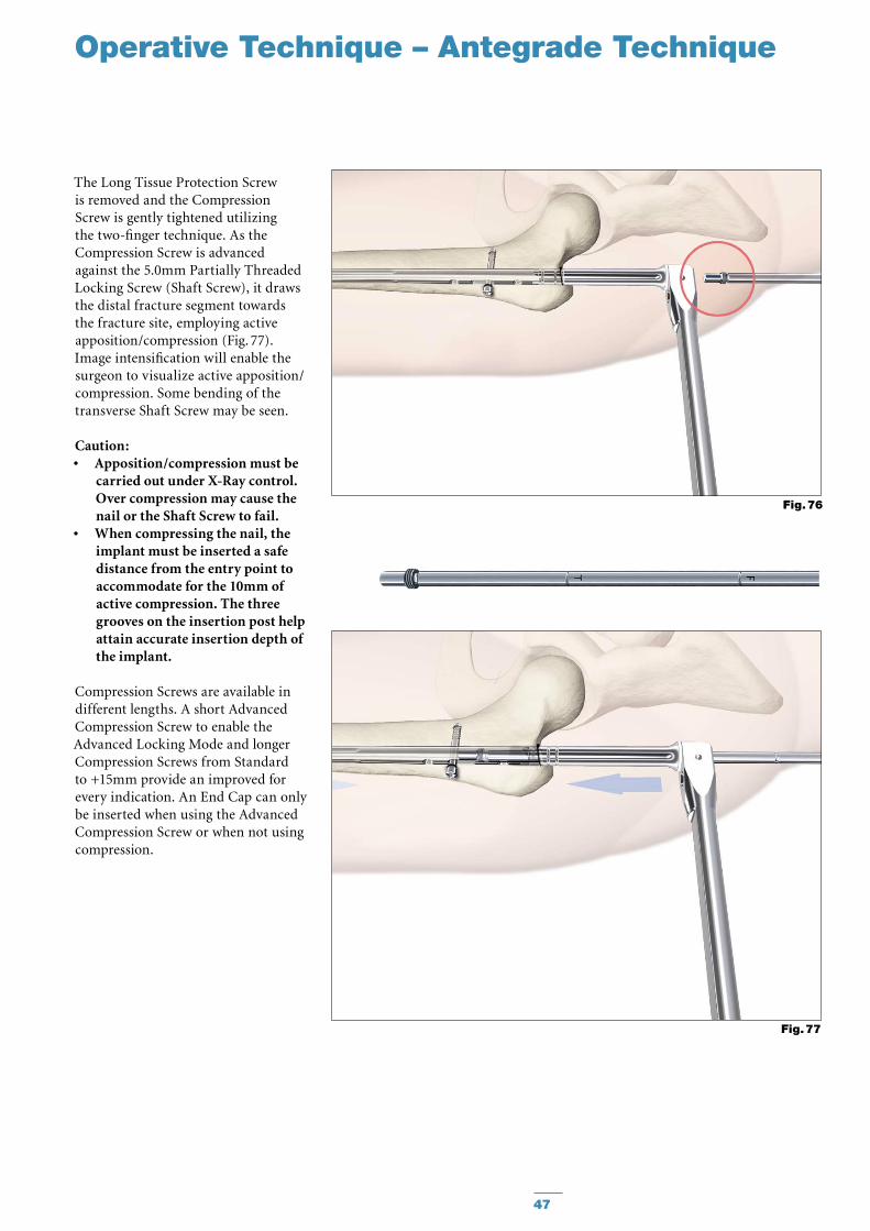
This will act as a guide for the Com-pression Screw. The Compression Screw is inserted with the Com-pression Screwdriver Shaft (1806-0268) and Teardrop Handle through the insertion post (Fig. 76). When the ring marked with an “F” on the Compression Screwdriver Shaft is close to the Target Device, it indicates the engagement of the apposition/compression feature of the nail. This applies only when the Advanced Compression Screw is used.
Note: The ring marked with a “T” is for the Tibial Compression Screw.
Fig. 75
47
Operative Technique – Antegrade Technique
The Long Tissue Protection Screw is removed and the Compression Screw is gently tightened utilizing the two-finger technique. As the Compression Screw is advanced against the 5.0mm Partially Thread ed Locking Screw (Shaft Screw), it draws the distal fracture segment towards the fracture site, employing active ap po si tion/compression (Fig. 77). Image intensification will enable the surgeon to visualize active apposition/compression. Some bending of the transverse Shaft Screw may be seen.
Caution: Apposition/compression must be •carried out under X-Ray control. Over compression may cause the nail or the Shaft Screw to fail.When compressing the nail, the •im plant must be inserted a safe distance from the entry point to accommodate for the 10mm of active com pression. The three grooves on the insertion post help attain accurate insertion depth of the implant.
Compression Screws are available in different lengths. A short Advanced Compression Screw to enable the Advanced Locking Mode and longer Compression Screws from Standard to +15mm provide an improved for every indication. An End Cap can only be inserted when using the Advanced Compression Screw or when not using compression.
Fig. 77
Fig. 76
48
Operative Technique – Antegrade Technique
In order to achieve additional fixation and to reduce the load on the Partially Threaded Locking Screw (Shaft Screw), an additional Locking Screw should also be inserted in the more distal or more proximal of the proximal locking holes depending on the fracture stability.
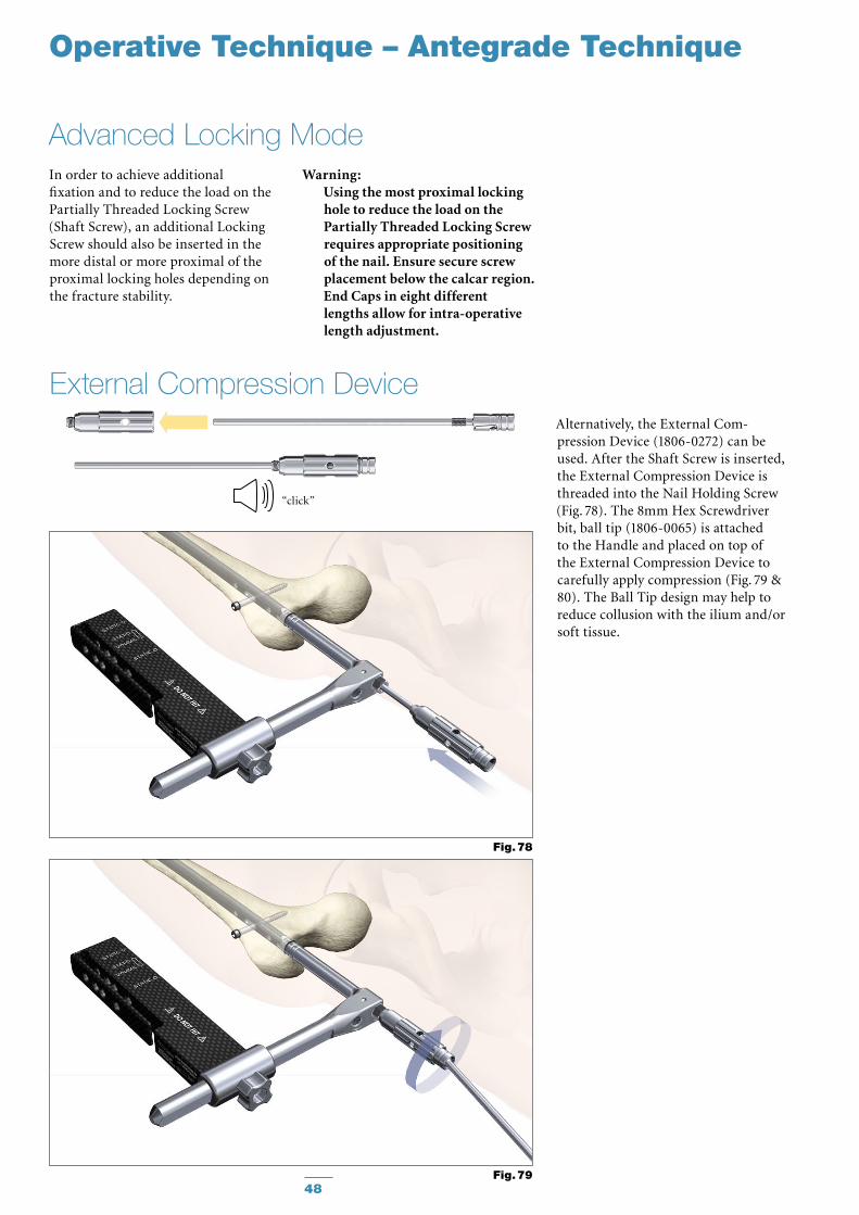
Alternatively, the External Com-pression Device (1806-0272) can be used. After the Shaft Screw is inserted, the External Compression Device is threaded into the Nail Holding Screw (Fig. 78). The 8mm Hex Screwdriver bit, ball tip (1806-0065) is attached to the Handle and placed on top of the External Compression Device to carefully apply compression (Fig. 79 & 80). The Ball Tip design may help to reduce collusion with the ilium and/or soft tissue.
External Compression Device
Advanced Locking ModeWarning:
Using the most proximal locking hole to reduce the load on the Partially Threaded Locking Screw requires appropriate positioning of the nail. Ensure secure screw placement below the calcar region. End Caps in eight different lengths allow for intra-operative length adjustment.
Fig. 78
Fig. 79
“click”
49
Operative Technique – Antegrade Technique
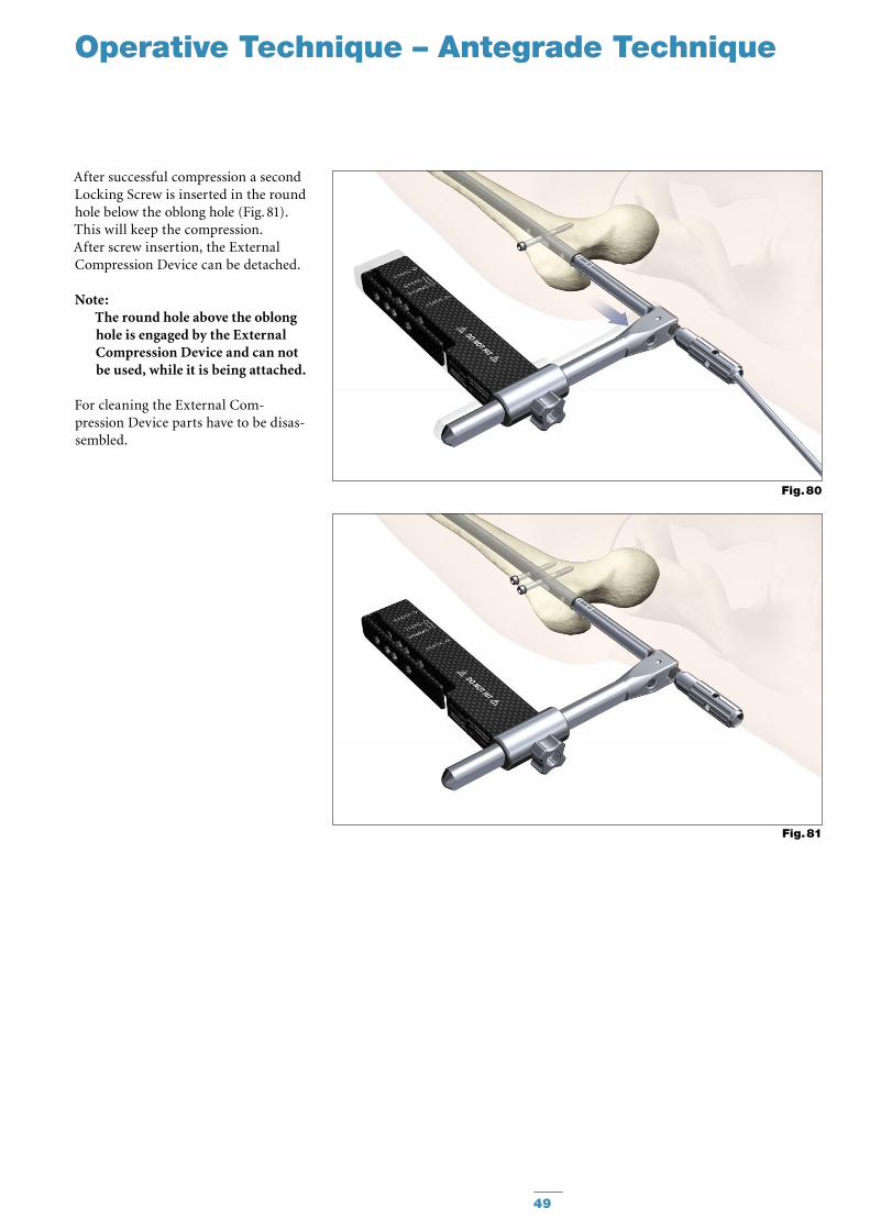
After successful compression a second Locking Screw is inserted in the round hole below the oblong hole (Fig. 81). This will keep the compression. After screw insertion, the External Compression Device can be detached.
Note: The round hole above the oblong hole is engaged by the External Compression Device and can not be used, while it is being attached.
For cleaning the External Com-pression Device parts have to be disas-sembled.
Fig. 80
Fig. 81
Operative Technique – Antegrade Technique
50
Nail removal is an elective procedure. If needed, the End Cap and Compres-sion Screw (if Advanced Locking Mode was utilized after the most distal screw is extracted) are removed with the Long Screwdriver Shaft and Teardrop Handle (Fig. 82).
The Self-holding Screwdriver Long (1806-0233) or Extra-short (1806-0203) can be used for Screw removal.
As an alternative to removing the Advanced Compression Screw (if used), it can be just disengaged from the Partially Threaded Locking Screw (Shaft Screw) by turning the Compression Screwdriver one full turn in a counter-clockwise direction. There is no need to remove it from the nail.
The Universal Rod is inserted into the driving end of the nail. All Locking Screws are removed with the Long Screwdriver Shaft and Teardrop Handle.
The Slotted Hammer is used to extract the nail in a controlled manner (Fig. 83). A captured Sliding Hammer (1806-0175) is available as an
“optional” instrument.
Note: Stryker offers also a Universal •Extraction Set for the removal of internal fixation systems and associated screws. For more information, please refer to the Literature Number B1000057.Check with local representative •regarding the availability of the Universal Extraction Set.
Nail Removal
Fig. 82
Fig. 83
Special Order
Implants in sterile
packaging.
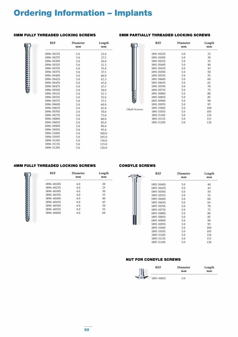
Note : Check with local repre-sentative regarding availability of nail sizes.
51
T2 FEMORAL LOCKING NAIL
REF Diameter Length mm mm
1825-1214S 12.0 140 1825-1216S 12.0 160 1825-1218S 12.0 180 1825-1220S 12.0 200 1825-1222S 12.0 220 1825-1224S 12.0 240 1825-1226S 12.0 260 1825-1228S 12.0 280 1825-1230S 12.0 300 1825-1232S 12.0 320 1825-1234S 12.0 340 1825-1236S 12.0 360 1825-1238S 12.0 380 1825-1240S 12.0 400 1825-1242S 12.0 420 1825-1244S 12.0 440 1825-1246S 12.0 460 1825-1248S 12.0 480
1825-1314S 13.0 140 1825-1316S 13.0 160 1825-1318S 13.0 180 1825-1320S 13.0 200 1825-1322S 13.0 220 1825-1324S 13.0 240 1825-1326S 13.0 260 1825-1328S 13.0 280 1825-1330S 13.0 300 1825-1332S 13.0 320 1825-1334S 13.0 340 1825-1336S 13.0 360 1825-1338S 13.0 380 1825-1340S 13.0 400 1825-1342S 13.0 420 1825-1344S 13.0 440 1825-1346S 13.0 460 1825-1348S 13.0 480
1825-1414S 14.0 140 1825-1416S 14.0 160 1825-1418S 14.0 180 1825-1420S 14.0 200 1825-1422S 14.0 220 1825-1424S 14.0 240 1825-1426S 14.0 260 1825-1428S 14.0 280 1825-1430S 14.0 300 1825-1432S 14.0 320 1825-1434S 14.0 340 1825-1436S 14.0 360 1825-1438S 14.0 380 1825-1440S 14.0 400 1825-1442S 14.0 420 1825-1444S 14.0 440 1825-1446S 14.0 460 1825-1448S 14.0 480
1825-1514S 15.0 140 1825-1516S 15.0 160 1825-1518S 15.0 180 1825-1520S 15.0 200 1825-1522S 15.0 220 1825-1524S 15.0 240 1825-1526S 15.0 260 1825-1528S 15.0 280 1825-1530S 15.0 300 1825-1532S 15.0 320 1825-1534S 15.0 340 1825-1536S 15.0 360 1825-1538S 15.0 380 1825-1540S 15.0 400 1825-1542S 15.0 420 1825-1544S 15.0 440 1825-1546S 15.0 460 1825-1548S 15.0 480
Ordering Information – Implants
REF Diameter Length mm mm
1825-0814S 8.0 140 1825-0816S 8.0 160 1825-0818S 8.0 180 1825-0820S 8.0 200 1825-0822S 8.0 220 1825-0824S 8.0 240 1825-0826S 8.0 260 1825-0828S 8.0 280 1825-0830S 8.0 300 1825-0832S 8.0 320 1825-0834S 8.0 340 1825-0836S 8.0 360 1825-0838S 8.0 380 1825-0840S 8.0 400 1825-0842S 8.0 420 1825-0844S 8.0 440 1825-0846S 8.0 460 1825-0848S 8.0 480
1825-0914S 9.0 140 1825-0916S 9.0 160 1825-0918S 9.0 180 1825-0920S 9.0 200 1825-0922S 9.0 220 1825-0924S 9.0 240 1825-0926S 9.0 260 1825-0928S 9.0 280 1825-0930S 9.0 300 1825-0932S 9.0 320 1825-0934S 9.0 340 1825-0936S 9.0 360 1825-0938S 9.0 380 1825-0940S 9.0 400 1825-0942S 9.0 420 1825-0944S 9.0 440 1825-0946S 9.0 460 1825-0948S 9.0 480
1825-1014S 10.0 140 1825-1016S 10.0 160 1825-1018S 10.0 180 1825-1020S 10.0 200 1825-1022S 10.0 220 1825-1024S 10.0 240 1825-1026S 10.0 260 1825-1028S 10.0 280 1825-1030S 10.0 300 1825-1032S 10.0 320 1825-1034S 10.0 340 1825-1036S 10.0 360 1825-1038S 10.0 380 1825-1040S 10.0 400 1825-1042S 10.0 420 1825-1044S 10.0 440 1825-1046S 10.0 460 1825-1048S 10.0 480
1825-1114S 11.0 140 1825-1116S 11.0 160 1825-1118S 11.0 180 1825-1120S 11.0 200 1825-1122S 11.0 220 1825-1124S 11.0 240 1825-1126S 11.0 260 1825-1128S 11.0 280 1825-1130S 11.0 300 1825-1132S 11.0 320 1825-1134S 11.0 340 1825-1136S 11.0 360 1825-1138S 11.0 380 1825-1140S 11.0 400 1825-1142S 11.0 420 1825-1144S 11.0 440 1825-1146S 11.0 460 1825-1148S 11.0 480
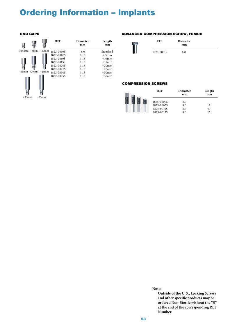
(Shaft Screws)
CONDyLE SCREWS
1895-5040S1895-5045S1895-5050S1895-5055S1895-5060S1895-5065S1895-5070S1895-5075S1895-5080S1895-5085S1895-5090S1895-5095S1895-5100S1895-5105S1895-5110S1895-5115S1895-5120S
404550556065707580859095
100105110115120
5.05.05.05.05.05.05.05.05.05.05.05.05.05.05.05.05.0
REF Diameter Length mm mm
NuT FOR CONDyLE SCREWS
1895-5001S 5.0
REF Diameter Length mm mm
REF Diameter Length mm mm
1896-4020S 4.0 201896-4025S 4.0 251896-4030S 4.0 301896-4035S 4.0 351896-4040S 4.0 401896-4045S 4.0 451896-4050S 4.0 501896-4055S 4.0 551896-4060S 4.0 60
4MM FuLLy ThREADED LOCKING SCREWS
52
5MM FuLLy ThREADED LOCKING SCREWS
Ordering Information – Implants
REF Diameter Length mm mm
5MM PARTIALLy ThREADED LOCKING SCREWS
1891-5025S1891-5030S1891-5035S1891-5040S1891-5045S1891-5050S1891-5055S1891-5060S1891-5065S1891-5070S1891-5075S1891-5080S1891-5085S1891-5090S1891-5095S1891-5100S1891-5105S1891-5110S1891-5115S1891-5120S
253035404550556065707580859095
100105110115120
5.05.05.05.05.05.05.05.05.05.05.05.05.05.05.05.05.05.05.05.0
REF Diameter Length mm mm
1896-5025S1896-5027S1896-5030S1896-5032S1896-5035S1896-5037S1896-5040S1896-5042S1896-5045S1896-5047S1896-5050S1896-5052S1896-5055S1896-5057S1896-5060S1896-5065S1896-5070S1896-5075S1896-5080S1896-5085S1896-5090S1896-5095S1896-5100S1896-5105S1896-5110S1896-5115S1896-5120S
5.0 25.05.0 27.55.0 30.05.0 32.55.0 35.0 5.0 37.55.0 40.0 5.0 42.55.0 45.0 5.0 47.5 5.0 50.05.0 52.5 5.0 55.0 5.0 57.5 5.0 60.0 5.0 65.0 5.0 70.0 5.0 75.0 5.0 80.0 5.0 85.0 5.0 90.0 5.0 95.0 5.0 100.05.0 105.05.0 110.05.0 115.05.0 120.0
REF Diameter Length mm mm
1822-0003S 8.0 Standard1822-0005S 11.5 + 5mm1822-0010S 11.5 +10mm1822-0015S 11.5 +15mm1822-0020S 11.5 +20mm1822-0025S 11.5 +25mm1822-0030S 11.5 +30mm1822-0035S 11.5 +35mm
END CAPS
+5mm +10mm
+15mm
Standard
+20mm +25mm
+30mm +35mm
1825-0000S1825-0005S1825-0010S1825-0015S
8.0 8.0 8.0 8.0
51015
REF Diameter Length mm mm
COMPRESSION SCREWS
1825-0001S 8.0
REF Diameter mm
ADVANCED COMPRESSION SCREW, FEMuR
53
Ordering Information – Implants
Note: Outside of the U. S., Locking Screws and other specific products may be ordered Non-Sterile without the “S” at the end of the corresponding REF Number.
54
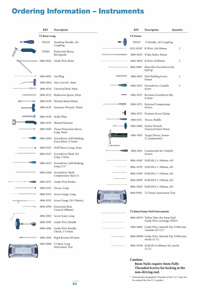
Ordering Information – Instruments
REF Description
T2 Basic Long
702429 Teardrop Handle, AO Coupling
703165 Protection Sleeve, Retrograde
1806-0022 Guide Wire Ruler
1806-0032 Awl Plug
1806-0041 Awl, Curved, 9mm
1806-0110 Universal Rod, 9mm
1806-0125 Reduction Spoon, 9mm
1806-0130 Wrench 8mm/10mm
1806-0135 Insertion Wrench, 10mm
1806-0150 Strike Plate
1806-0170 Slotted Hammer
1806-0185 Tissue Protection Sleeve, Long, 9mm
1806-0203 Screwdriver, Self-Holding, Extra Short (3.5mm)
1806-0215 Drill Sleeve, Long, 5mm
1806-0227 Screwdriver Shaft AO, Long, 3.5mm
1806-0233 Screwdriver, Self-Holding, Long (3.5)
1806-0268 Screwdriver Shaft, Compression (hex3.5)
1806-0271 Guide Wire Pusher
1806-0315 Trocar, Long
1806-0325 Screw Gauge, Long
1806-0331 Screw Gauge (20-120mm)
1806-0350 Extraction Rod, Conical (Ø8mm)
1806-0365 Screw Scale, Long
1806-1095 Guide Wire Handle
1806-1096 Guide Wire Handle Chuck, 2-3.5mm
1806-2014 Rigid Reamer Ø12mm
1806-9900 T2 Basic Long Instrument Tray
REF Description Quantity
T2 Femur
702427 T-Handle, AO Coupling
0152-0218* K-Wire 1,8x310mm 2
1806-0015 X-Ray Ruler, Femur
1806-0050 K-Wire 3x285mm 2
1806-0065 8mm Hex Screwdriver bit, ball tip
1806-0165 Nail Holding Screw, 2 Femur
1806-0255 Screwdriver, Condyle 2 Screw
1806-0257 Revision Screwdriver Bit, 6.3mm
1806-0272 External Compression Device
1806-0273 Fixation Screw Clamp
1806-0311 Trocar, Paddle
1806-0400 Socket Wrench, Universal Joint 10mm
1806-1005 Target Device, Femur (2 components)
1806-2016 Countersink for Condyle Screws
1806-4260* Drill Ø4.2 × 340mm, AO
1806-4270* Drill Ø4.2 × 180mm, AO
1806-4290* Drill Ø4.2 × 230mm, AO
1806-5000* Drill Ø5.0 × 230mm, AO
1806-5020* Drill Ø5.0 × 340mm, AO
1806-9920 T2 Femur Instrument Tray
T2 8mm Femur Nail Instruments
1806-0073S Teflon Tube (for 8mm Nail Guide Wire exchange ONLY)
1806-0090 Guide Wire, Smooth Tip 3×800 mm (outside of U. S.)*
1806-0090S Guide Wire, Smooth Tip 3×800 mm, sterile (U. S.)
1806-3570S Drill Ø3.5×180mm AO, sterile (U. S.)
* Instruments designated “Outside of the U. S.” may not be ordered for the U. S. market.
Caution: 8mm Nails require 4mm Fully Threaded Screws for locking at the non-driving end.
55
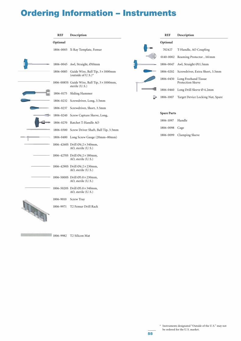
Ordering Information – Instruments
* Instruments designated “Outside of the U. S.” may not be ordered for the U. S. market.
REF Description
Optional
702427 T-Handle, AO Coupling
0140-0002 Reaming Protector , 161mm
1806-0047 Awl, Straight Ø11.5mm
1806-0202 Screwdriver, Extra Short, 3.5mm
1806-0450 Long Freehand Tissue Protection Sleeve
1806-0460 Long Drill Sleeve Ø 4.2mm
1806-1007 Target Device Locking Nut, Spare
Spare Parts
1806-1097 Handle
1806-0098 Cage
1806-0099 Clamping Sleeve
REF Description
Optional
1806-0005 X-Ray Template, Femur
1806-0045 Awl, Straight, Ø10mm
1806-0085 Guide Wire, Ball Tip, 3 × 1000mm (outside of U. S.)* 1806-0085S Guide Wire, Ball Tip, 3 × 1000mm, sterile (U. S.)
1806-0175 Sliding Hammer
1806-0232 Screwdriver, Long, 3.5mm
1806-0237 Screwdriver, Short, 3.5mm
1806-0240 Screw Capture Sleeve, Long,
1806-0270 Ratchet T-Handle AO
1806-0300 Screw Driver Shaft, Ball Tip, 3.5mm
1806-0480 Long Screw Gauge (20mm–80mm)
1806-4260S Drill Ø4.2 × 340mm, AO, sterile (U. S.)
1806-4270S Drill Ø4.2 × 180mm, AO, sterile (U. S.)
1806-4290S Drill Ø4.2 × 230mm, AO, sterile (U. S.)
1806-5000S Drill Ø5.0 × 230mm, AO, sterile (U. S.)
1806-5020S Drill Ø5.0 × 340mm, AO, sterile (U. S.)
1806-9010 Screw Tray
1806-9971 T2 Femur Drill Rack
1806-9982 T2 Silicon Mat
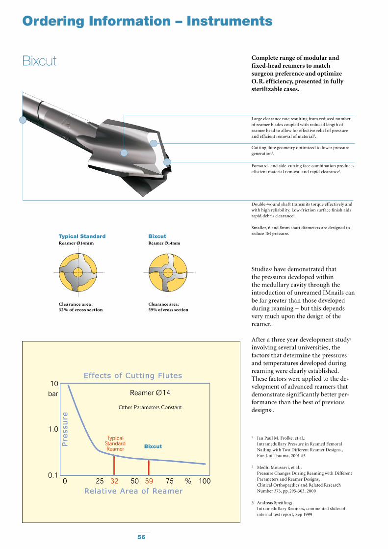
Complete range of modular and fixed-head reamers to match surgeon preference and optimize O. R. efficiency, presented in fully sterilizable cases.
Studies1 have demonstrated that the pressures developed within the medullary cavity through the introduction of unreamed IMnails can be far greater than those devel oped during reaming − but this depends very much upon the design of the reamer.
After a three year development study2 involving several universities, the factors that determine the pressures and temperatures developed during reaming were clearly established. These factors were applied to the de -velopment of advanced reamers that demonstrate significantly better per -form ance than the best of previous designs3.
1 Jan Paul M. Frolke, et al. ; Intramedullary Pressure in Reamed Femoral
Nailing with Two Different Reamer Designs., Eur. J. of Trauma, 2001 #5
2 Medhi Moussavi, et al.; Pressure Changes During Reaming with Different
Parameters and Reamer Designs, Clinical Orthopaedics and Related Research
Number 373, pp. 295-303, 2000
3 Andreas Speitling; Intramedullary Reamers, commented slides of internal test report, Sep 1999
Large clearance rate resulting from reduced number of reamer blades coupled with reduced length of reamer head to allow for effective relief of pressure and efficient removal of material3.
Cutting flute geometry optimized to lower pressure generation3.
Forward- and side-cutting face combination produces efficient material removal and rapid clearance3.
Double-wound shaft transmits torque effectively and with high reliability. Low-friction surface finish aids rapid debris clearance3.
Smaller, 6 and 8mm shaft diameters are designed to reduce IM pressure.
Typical StandardReamer Ø14mm
Clearance area :32% of cross section
BixcutReamer Ø14mm
Clearance area :59% of cross section
Ordering Information – Instruments
56
Bixcut
Bixcut
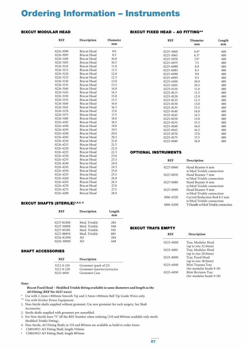
REF Description Diameter mm
BIxCuT MODuLAR hEAD
REF Diameter Length mm mm
BIxCuT FIxED hEAD − AO FITTING**
REF Description Length mm
BIxCuT ShAFTS (STERILE)1,2,3, 4
REF Description
ShAFT ACCESSORIES
REF Description
BIxCuT TRAyS EMPTy
Ordering Information – Instruments
REF Description
OPTIONAL INSTRuMENTS
0227-0060 Hand Reamer 6 mm w/Mod Trinkle connection
0227-0070 Hand Reamer 7 mm w/Mod Trinkle connection
0227-0080 Hand Reamer 8 mm w/Mod Trinkle connection
0227-0090 Hand Reamer 9 mm w/Mod Trinkle connection
1806-6520 Curved Reduction Rod 8.5 mm w/Mod Trinkle connection
1806-6500 T-Handle w/Mod Trinkle connection
0226-30900226-30950226-31000226-31050226-31100226-31150226-31200226-31250226-31300226-31350226-31400226-31450226-31500226-31550226-31600226-31650226-31700226-31750226-31800226-41850226-41900226-41950226-42000226-42050226-42100226-42150226-42200226-42250226-42300226-42350226-42400226-42450226-42500226-42550226-42600226-42650226-42700226-42750226-4280
Bixcut HeadBixcut HeadBixcut HeadBixcut HeadBixcut HeadBixcut HeadBixcut HeadBixcut HeadBixcut HeadBixcut HeadBixcut HeadBixcut HeadBixcut HeadBixcut HeadBixcut HeadBixcut HeadBixcut HeadBixcut HeadBixcut HeadBixcut HeadBixcut HeadBixcut HeadBixcut HeadBixcut HeadBixcut HeadBixcut HeadBixcut HeadBixcut HeadBixcut HeadBixcut HeadBixcut HeadBixcut HeadBixcut HeadBixcut HeadBixcut HeadBixcut HeadBixcut HeadBixcut HeadBixcut Head
9.09.5
10.010.511.011.512.012.513.013.514.014.515.015.516.016.517.017.518.018.519.019.520.020.521.021.522.022.523.023.524.024.525.025.526.026.527.027.528.0
0227-8240S Mod. Trinkle 284 0227-3000S Mod. Trinkle 448 0227-8510S Mod. Trinkle 510 0227-8885S Mod. Trinkle 885 0226-8240S AO 284 0226-3000S AO 448 0225-6000 Tray, Modular Head
(up to size 22.0mm) 0225-6001 Tray, Modular Head (up to size 28.0mm) 0225-8000 Tray, Fixed Head (up to size 18.0mm) 0225-6040 Mini Trauma Tray (for modular heads 9-18) 0225-6050 Mini Revision Tray (for modular heads 9-28)
0225-50600225-50650225-50700225-60750225-60800225-60850225-60900225-60950225-61000225-61050225-61100225-81150225-81200225-81250225-81300225-81350225-81400225-81450225-81500225-81550225-81600225-81650225-81700225-81750225-8180
6.0*6.5*7.0*7.58.08.59.09.5
10.010.511.011.512.012.513.013.514.014.515.015.516.016.517.017.518.0
400400400480480480480480480480480480480480480480480480480480480480480480480
3212-0-210 Grommet (pack of 25) 3212-0-220 Grommet inserter/extractor 0225-6010 Grommet Case
Note: Bixcut Fixed Head − Modified Trinkle fitting available in same diameters and length as the AO Fitting (REF No: 0227-xxxx)
* Use with 2.2mm × 800mm Smooth Tip and 2.5mm × 800mm Ball Tip Guide Wires only.** Use with Stryker Power Equipment.1. Non-Sterile shafts supplied without grommet. Use new grommet for each surgery. See Shaft
Accessories.2. Sterile shafts supplied with grommet pre-assembled.3. For Non-Sterile leave “S” off the REF Number when ordering (510 and 885mm available only sterile
Modified Trinkle Fitting).4. Non-Sterile, AO Fitting Shafts in 510 and 885mm are available as build to order items:
CM810921 AO Fitting Shaft, length 510mm• CM810923 AO Fitting Shaft, length 885mm.•
57

Notes
58

Notes
59

Stryker Trauma GmbHProf.-Küntscher-Straße 1–5D - 24232 SchönkirchenGermany
www.osteosynthesis.stryker.com
This document is intended solely for the use of healthcare professionals. A surgeon must always rely on his or her own professional clinical judgment when deciding whether to use a particular product when treating a particular patient. Stryker does not dispense medical advice and recommends that surgeons be trained in the use of any particular product before using it in surgery. The information presented in this brochure is intended to demonstrate a Stryker product. Always refer to the package insert, product label and/or user instructions including the instructions for Cleaning and Sterilization (if applicable) before using any Stryker products. Products may not be available in all markets. Product availability is subject to the regulatory or medical practices that govern individual markets. Please contact your Stryker representative if you have questions about the availability of Stryker products in your area.
Stryker Corporation or its divisions or other corporate affiliated entities own, use or have applied for the following trade-marks or service marks: Stryker, T2 and BixCut.
All other trademarks are trademarks of their respective owners or holders.The products listed above are CE marked.
Literature Number : B1000004LOT G4909
Copyright © 2010 Stryker