t tomorrow - technip document is printed on heaven 42 ... international conference on ocean,...
TRANSCRIPT

T
Anti H2S ETH-PIP Technology HVS SemiSmall Scale LNG
Tomorrow - August 2012
TOMORROWA Technip Technology Publication - Issue 1 - August 2012

P. 10-11
P. 8-9
Small Scale LNG A tailor made solution built on experience
HVS Semi The story of CFD and HVS
P. 6-7 Heating up flowlinesTechnip’s innovation heats up flowlines
P. 4-5 Limiting corrosion in flexibles
The Anti H2S
TomorrowA Technip Technology PublicationIssue 1 – August 2012
You can find this issue at: http://www.technip.com/en/media-centerYour comments are always welcome: [email protected]
Director of Publication: Christophe BélorgeotChief Editor: Trina OakeAssociate Editors - August 2012 issue: Andrea Gragnani, Brian Lynch, Brian Rob-erts, Jean-Pascal Biaggi, Jeroen Remery, Mohamed Ould-Bamba, Philip Hagyard, Robby O’Sullivan, Stephane His, Sylvain DennielPhotography: Technip image libraryDesign and production: Lydia Marchetti
The Group Communications Department would like to thank everyone that has contributed to this issue.Technip - 89 avenue de la Grande Armée - 75116 Paris - France
This document is printed on Heaven 42
I would like to personally welcome you to the first issue of Technip’s new technology magazine, aptly named ‘Tomorrow’. This publication will focus on Technip’s differentiation in the energy industry through innovative technology in all of our business sectors. Each and every day, our teams play a part in meeting tomorrow’s world energy challenge and are involved in projects with a high level of technological input. Innova-tion is at the heart of all our activities and helps us meet our
clients’ needs effectively and provide tailored, high performance solutions.
In the Subsea segment, we are a vertically-integrated leader, committed to being at the forefront of frontier developments. Our commitment to technologies, combined with our leading-edge fleet and international assets enables us to make Technip a global player from deep to shore.
Our offshore activities include engineering, procurement, construction and installation of fixed and floating platforms. Technip has developed world-class standards and advanced technologies to deliver fit-for-purpose solutions, designed to overcome the challenges of shallow and ultra-deepwater as well as harsh environments.
Technip’s onshore activity covers the full range of onshore installations required to meet the production, processing and transportation needs of the oil and gas, petrochemical and other industries, in particular renewable energies and mining and metals.
While technological innovation is of utmost importance to Technip, there is also a strong commitment to reaching the highest standards of health, safety, environment (HSE) and quality. We continue to challenge and improve our approach to HSE management and look for innovative ways to improve performance and set the benchmark for our industry.
In the markets where we operate, we are known for our clients’ focus, our integrated and sustainable project ap-proach, our technological expertise and our know-how in project management. All of which are essential factors in our strategy to strengthen our profitable and sustainable growth. Thanks to our people, assets, and of course our technology, we are well positioned in all areas to take Technip further.
I hope you enjoy this, and future issues, of ‘Tomorrow’.
«Thanks to our people,
assets, market positions,
and of course our
technology, we are well
positioned to take
Technip further.»
Thierry Pilenko Chairman and CEO
This document is the property of Technip and is not intended to be a binding contractual document. Any information contained herein shall not result in any binding obligation on
the part of Technip, or any of its affiliates, and is provided for information purposes only.
Tomorrow - August 2012
EDITORIAL

ZnO
Zn Zn
O
OH
HH
HS
S
H2S+ ZnS H2O+
Zinc Oxide and Hydrogen Sulfide result in Zinc Sulfide and Water
© Stéphane Jungers
4 - 5
Tomorrow - August 2012
Corrosive gases present in the oil production flow have a significant impact on the design and cost of a flexible pipe. Now, a new Technip technology provides a step change in the management of the design and cost implications. Additionally, it expands the domain of application of flexible pipe.
When applicable, these tech-nological advances can result in significant cost savings, poten-tially as much as 20%. This new technology was presented at the 2011 OTC(1) and the OMAE(2) industry conferences and
generated considerable interest and positive feedback from attendees. It contributes to the resolution of a growing concern among oil and gas operators, namely the increase of sour fluids observed in subsea
reservoirs. Our clients show a marked interest in this innova-tion.
(1) Offshore Technology Conference
(2) International Conference on Ocean,
Offshore and Artic Engineering
The ‘Anti-H2S’ material devel-oped by Technip is called PEZnO and is composed of a thermoplastic matrix in poly-ethylene (PE) compounded with zinc oxide (ZnO) and iron oxide (Fe2O3). Zinc oxide is a
common and cheap material often used in the cosmetics industry. Both oxides will react with H2S. The reaction with ZnO will be responsible for the efficiency of the system, whereas Fe203, which gives
its initial purple color to the material, will be used as a visual tracer of the reaction with H2S. The main, non-reversible, reaction taking place in the ‘Anti-H2S’ material can be seen in the illustration below.
The ‘Anti-H2S’ layer principleThe ‘Anti-H2S’ layer is a continuous leak proof sheath placed between the pressure sheath and the pressure vault. The metallic oxide additives within the layer will chemically react with the H2S entering the ‘Anti H2S’ sheath after permeation through the pres-sure sheath. This reaction will act as a barrier to H2S during all the service life of the flexible pipe.
How Technip innovation limits corrosion in flexibles. Flexible pipes are extensively used for oil and gas develop-ment and transport of the production flow, which often contain corrosive fluids in the form of water (H2O), carbon dioxide (CO2) and hydrogen sulfide (H2S). Even if these fluids are not in direct contact with the “annulus” steel layers of the pipe they will diffuse through
the pressure sheath, thereby creating a corrosive environ-ment for these carbon steel layers. This necessitates the use of pressure and tensile armour wires made of sour service steel grades, instead of sweet ser-vice steel grades. Sour service steel grades are both lower in strength and higher in cost than the equivalent sweet service material. The new Technip patented technology revolutionizes
flexible pipe annulus manage-ment through the introduction of a new sheath, the so called ‘Anti-H2S’ layer. This layer is a leak-proof sheath made of a composite material which is placed between the pressure sheath and the pressure vault. The material is designed to consume the H2S by a chemical reaction before it can perme-ate through to the carbon steel pipe annulus. This technology, developed by Technip and IFP
Energies Nouvelles, permits the use of sweet steel grades, with high mechanical properties, in the annulus of flexible pipes, even when the fluid contains H2S. The main team involved in the development of this new tech-nology is the Product Engineer-ing Division (PED) which is the flexible pipe technology center for the Group located in Le Trait, France.
H2S
H2S
Thickness of the ‘Anti-H2S’ sheath
Thickness of the Pressure sheath
PEZnS PEZnO
Annulus(3)
A
BC
External sheathMade of polymer to ensure tightness of the annulus regarding external environment.
The ArmoursMade of one or two pairs of helicoidally spiraled steel wires and designed to ensure structural strength.
Pressure vault
Anti-H2S sheathComposite material: Polyethylene + ZnO (PEZnO). The Zinc Oxide will neutralize the H2S during the entire service life.
Pressure sheathH2S permeates through this sheath. It regulates the H2S flowrate that arrives at the second sheath.
CarcassMade of stainless steel, in direct contact with the transported fluid and sustaining the external pressure.
This layer sustains internal pressure thanks to a vault wire spiraled at short pitch.
(3) The annulus is the space between pressure sheath and external sheath. It is typically made of the pressure vault and the armour wires
Step A : H2S transport through pressure sheath.Step B : H2S transport through PEZnS (“Anti-H2S” material already reacted).Step C : H2S reaction with ZnO.
Chemical reaction principle
Positive feedback from our clients
© Stéphane Jungers © Stéphane Jungers
For further information, please visit http://www.technip.com/en/our-business/sub-sea/flexible-pipe or contact [email protected]
The Anti - H2S Layer
6 - 7
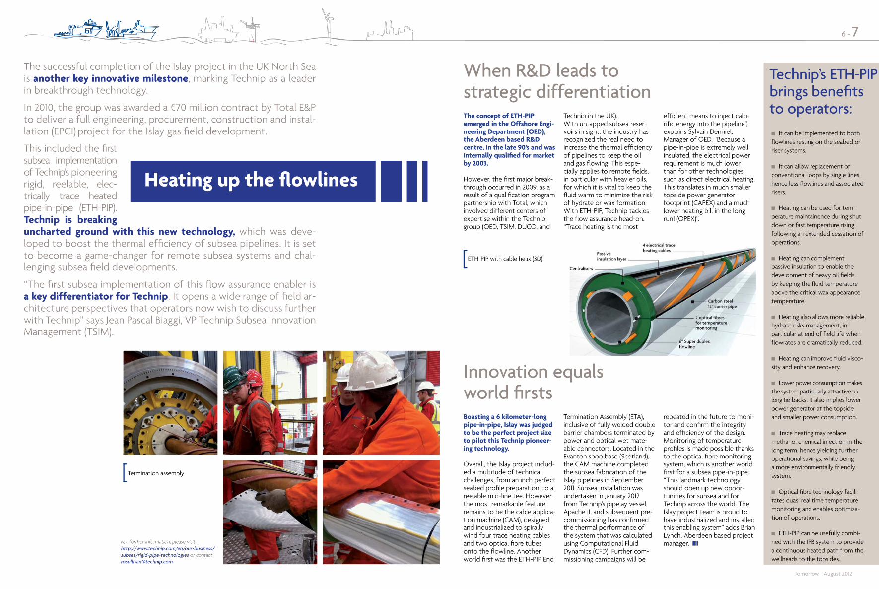
When R&D leads to strategic differentiationThe concept of ETH-PIP emerged in the Offshore Engi-neering Department (OED), the Aberdeen based R&D centre, in the late 90’s and was internally qualified for market by 2003. However, the first major break-through occurred in 2009, as a result of a qualification program partnership with Total, which involved different centers of expertise within the Technip group (OED, TSIM, DUCO, and
Technip in the UK). With untapped subsea reser-voirs in sight, the industry has recognized the real need to increase the thermal efficiency of pipelines to keep the oil and gas flowing. This espe-cially applies to remote fields, in particular with heavier oils, for which it is vital to keep the fluid warm to minimize the risk of hydrate or wax formation. With ETH-PIP, Technip tackles the flow assurance head-on. “Trace heating is the most
efficient means to inject calo-rific energy into the pipeline”, explains Sylvain Denniel, Manager of OED. “Because a pipe-in-pipe is extremely well insulated, the electrical power requirement is much lower than for other technologies, such as direct electrical heating. This translates in much smaller topside power generator footprint (CAPEX) and a much lower heating bill in the long run! (OPEX)”.
Innovation equals world firstsBoasting a 6 kilometer-long pipe-in-pipe, Islay was judged to be the perfect project size to pilot this Technip pioneer-ing technology. Overall, the Islay project includ-ed a multitude of technical challenges, from an inch perfect seabed profile preparation, to a reelable mid-line tee. However, the most remarkable feature remains to be the cable applica-tion machine (CAM), designed and industrialized to spirally wind four trace heating cables and two optical fibre tubes onto the flowline. Another world first was the ETH-PIP End
Termination Assembly (ETA), inclusive of fully welded double barrier chambers terminated by power and optical wet mate-able connectors. Located in the Evanton spoolbase (Scotland), the CAM machine completed the subsea fabrication of the Islay pipelines in September 2011. Subsea installation was undertaken in January 2012 from Technip’s pipelay vessel Apache II, and subsequent pre-commissioning has confirmed the thermal performance of the system that was calculated using Computational Fluid Dynamics (CFD). Further com-missioning campaigns will be
repeated in the future to moni-tor and confirm the integrity and efficiency of the design. Monitoring of temperature profiles is made possible thanks to the optical fibre monitoring system, which is another world first for a subsea pipe-in-pipe. “This landmark technology should open up new oppor-tunities for subsea and for Technip across the world. The Islay project team is proud to have industrialized and installed this enabling system” adds Brian Lynch, Aberdeen based project manager.
Termination assembly
ETH-PIP with cable helix (3D)
Tomorrow - August 2012
It can be implemented to both flowlines resting on the seabed or riser systems.
It can allow replacement of conventional loops by single lines, hence less flowlines and associated risers.
Heating can be used for tem-perature maintainence during shut down or fast temperature rising following an extended cessation of operations.
Heating can complement passive insulation to enable the development of heavy oil fields by keeping the fluid temperature above the critical wax appearance temperature.
Heating also allows more reliable hydrate risks management, in particular at end of field life when flowrates are dramatically reduced.
Heating can improve fluid visco-sity and enhance recovery.
Lower power consumption makes the system particularly attractive to long tie-backs. It also implies lower power generator at the topside and smaller power consumption.
Trace heating may replace methanol chemical injection in the long term, hence yielding further operational savings, while being a more environmentally friendly system.
Optical fibre technology facili-tates quasi real time temperature monitoring and enables optimiza-tion of operations.
ETH-PIP can be usefully combi-ned with the IPB system to provide a continuous heated path from the wellheads to the topsides.
Technip’s ETH-PIP brings benefits to operators:
The successful completion of the Islay project in the UK North Sea is another key innovative milestone, marking Technip as a leader in breakthrough technology.
In 2010, the group was awarded a €70 million contract by Total E&P to deliver a full engineering, procurement, construction and instal-lation (EPCI) project for the Islay gas field development.
This included the first subsea implementation of Technip’s pioneering rigid, reelable, elec-trically trace heated pipe-in-pipe (ETH-PIP).Technip is breaking uncharted ground with this new technology, which was deve-loped to boost the thermal efficiency of subsea pipelines. It is set to become a game-changer for remote subsea systems and chal-lenging subsea field developments.
“The first subsea implementation of this flow assurance enabler is a key differentiator for Technip. It opens a wide range of field ar-chitecture perspectives that operators now wish to discuss further with Technip” says Jean Pascal Biaggi, VP Technip Subsea Innovation Management (TSIM).
For further information, please visit http://www.technip.com/en/our-business/subsea/rigid-pipe-technologies or contact [email protected]
Heating up the flowlines

The initial response to reduce the motions of a semi-submers-ible was to increase its draft. However, one effect of this is that the longer columns become prone to Vortex Induced Motion (VIM). VIM is an issue with Spar platforms due to their deep draft, but it can be reduced by fitting strakes which discourage vortex shedding. Unfortunately, it is impractical to fit strakes to a semi-submersible vessel since a large proportion of their column height is in the splash zone where wave action would damage the strakes. As a result, a different solution was needed.
It was at this point that Technip decided that a better under-standing of VIM was required to determine ways of reducing it. Fortunately, Technip had developed an industry leading capability in Computational Fluid Dynamic (CFD) modeling and was able not only to visualize the vortices that are responsible for VIM, but also to experiment with different hull geometries to see what increased, and reduced, their occurrence. After much study work and optimization, this CFD work gave birth to the Heave and VIM Suppressed (HVS) semi. The HVS hull has a clever combination of pontoon and blister geometry that helps to reduce vortex shedding, and also tends to cancel out the effects of those that do form.
Technip has verified the HVS performance by model basin tests, but its lower hull shape could not have been conceived and developed without CFD to understand the science of VIM. It would have been impractical and too expensive to build and test a random array of different scale models in a wave tank.
8 - 9
Jim is confident that Technip will get an order for an HVS soon and says, “The HVS is an elegant solution to a difficult problem. In essence, the HVS is like a con-ventional semi, except the lower hull has a unique shape in the form of sharp edged blisters and narrow pontoons. From the tests we have run
in Gulf of Mexico conditions, heave is reduced by 35-50% and VIM by 50% for critical headings - this causes a major reduc-tion in SCR fatigue damage. The HVS hull design is also simpli-fied by adopting the Spar’s ballast system, which eliminates pump rooms at the base of the columns and results in a lower
cost hull and less risk to the crew. All in all, the HVS does not represent a departure from existing proven technologies, it is a clever way of packag-ing existing features. It is a low risk, high reward design that is certainly generating considerable interest from the operators with whom I have been in contact.”
So having developed the HVS and confirmed its performance, the next stage was for Technip to bring it to market and at this point, James (Jim) Ermon was appointed commercial man-ager. Jim has already contacted several interested clients, has talked with fabricators to gain their endorsement that
fabricating the HVS will be no different from a conventional semi-sub, and has presented papers on the HVS at industry conferences on behalf of Technip (the most recent being at MCEDD in Paris on 28th March 2012).
So hopefully, Technip will be able to report in future issues of ‘Tomorrow’, some new acronyms for the HVS: approval to tender (ATT), approval to commit (ATC) and approved for construction (AFC) – the list is endless.
HVS Semi illustration
James (Jim) ErmonVP – HVS Semi, Offshore BU
Tomorrow - August 2012
For further information, please visit http://www.technip.com/en/our-business/offshore/other-offshore-concepts or contact [email protected]
Several years ago, the offshore industry learned that Steel Cate-nary Risers (SCRs) were particularly sensitive to the motions of the floating platform that supports them. When the support platform has a very low-motion hull, such as a Spar, the excursions are rela-tively small. However this is not the case for semi-submersible vessels. SCRs tend to experience their highest fatigue damage at their touchdown point, that is, where the suspended SCR first rests on the seabed. In some ear-ly semi-submersible projects with SCRs, the fatigue damage at this location was so high that the platform had to be periodically moved to deliberately distribute the damage along the length of the SCR in order to meet the de-sign life of the field. Clearly this was unsatisfactory and Technip’s quest for a lower motion semi-submersible hull commenced.
The story of CFD and the HVS
HVS Semi

A
LNG TRUCKS
Small scale LNG plants can be divided into two categories.
The first category is low end capacity or Mini LNG. This category is used for peak shaving, distribution of natural gas to satellite stations by road and truck refuelling. In this case, the liquefaction process uses a plate fin heat exchanger (PFHE) in a cold box. The unit is generally assembled on skids in a fabrication shop.
The second category is high end capacity or small to medium scale LNG. This is generally used for liquefaction of gas from remote inland fields. The liquefaction process generally uses spiral wound heat exchangers (SWHEs). Many projects of this type are underway in China.
In remote inland regions, small scale liquefied natural gas plants offer the means to monetize natural gas that is in excess of local requirements. These plants are also a viable alternative to gas transportation by using long pipe-lines to more than onelocation, and can be used in low density popu-lation areas as well as in big cities. Technip’s long standing experience of successfully developed world scale LNG projects helps us to deliver small and mid-scale LNG plant projects.
Small scale LNG is produced no differently from large scale LNG.
The gas is conveyed via a high-pressure gas pipeline from the production field (or from a regional pipeline network) to the liquefaction plant. The gas is then pre-treated to remove components that are either toxic (hydrogen sulfide, mercaptans), corrosive (mer-cury), or could freeze at low temperatures (carbon dioxide, water, heavy hydrocarbon) and possibly plug cryogenic equip-ment.
To be liquefied, the gas is cooled to –162°C in the refrig-eration and liquefaction sec-tions. This process reduces the volume of the gas 600 times, compared to 100-200 times for compression/pipeline systems.
There are several liquefaction technologies available for small scale LNG capacities. Technip offers Air Products’ nitrogen cycle (N2), single mixed refrig-erant (SMR) process and the propane pre-cooled mixed refrigerant (C3MR) process.
Storage and distribution of small scale LNG by road trucks is suited to deliveries of small batches of LNG by land (as opposed to massive ocean going LNG carriers for interna-tional bulk trade).
In the regasification plant (or satellite stations), the LNG is stored in large vertical or hori-zontal cylinders. It is pumped to high pressure and heated by air to resume its gaseous state before being introduced to the local distribution network or routed to an industrial con-sumer.
When LNG is to be used as a transport fuel, it can be transferred directly to the tank of a heavy duty vehicle (truck, locomotive, mining machin-ery) as a cryogenic liquid, or regasified at high pressure and transferred to personal vehicles via a compressed natural gas dispenser.
Small scale LNG also allows the reduction of associated gas fla-ring (150 billion cubic meters of natural gas flared per year).
LNG as truck fuel is an attrac-tive alternative for diesel and more efficient than Com-pressed Natural Gas (CNG). This is due to a much shorter loading time and favorable engine performance, with fewer emissions and much less noise. This is important in the market due to growing environmental pressures, for example, the new stringent environmental requirements on emissions of nitrogen oxide (NOx) and sulphur oxide (SOx) for shipping in regulated areas.
China is the leading market today.
In recent years, the small scale LNG business has been developing in China, where there is a demand in several regions that have insufficient pipeline construction projects in the medium term. Numer-ous plants are in operation and many more projects are planned. Technip also sees the potential in many other countries such as India, Brazil, Norway, USA, Canada and Russia.
A tailor made solution built on experience
Market drivers
10 - 11
Ningxia Hanas, 2011 Small scale, but largest LNG plant in China
Discover a video of the Hanas project in China http://www.technip.com/ media-center/video
Ningxia Hanas is a prime example of the application of LNG to small scale distribution.
Technip recently started up Hanas LNG, and although it is classified as small-scale LNG, it is the largest LNG plant in China. This plant is a two-train project (0.4 Mtpa(1) per train) using Air Products’ single mixed refrigerant (SMR) process. The Hanas plant is electrically driven and air-cooled and includes several innovations:
Technip’s first LNG project entirely managed from Asia Pacific;
Delivery of the spiral wound exchanger to site as multiple independent exchangers in order to overcome transport constraints;
A hydrodynamic, variable speed torque converter between a fixed speed, elec-tric motor and the mixed refrigerant compressor to avoid depressuring prior to restart;
Heavy hydrocarbon removal on adsorbent beds allowing high pressure liquefaction; and
An “emulated” operation training simulator to prepare for start-up well in advance.
The gas is liquefied in Yinchuan, the capital of Ningxia prov-ince (center north of China), then transported by trucks to consumers, thousands of kilometers away.
(1) Million metric tonnes per annum
> 6 Mtpa = Mega trains
3 – 5 Mtpa = Large trains
1 – 2 Mtpa = Medium trains
0.3 – 0.5 Mtpa = Small trains
+/- 0.1 Mtpa = Mini trains
DEFINITIONS
The International Gas Union has fixed the following definitions:
Tomorrow - August 2012
Typical block diagram of a small scale LNG plant
Small scale LNG

Our values are operational they inspire our teams
and our clients experience them
Doing the right thing
Encouraging a fair return for all
Building the future
Trusting the team