system requirements for intersection conflict warning … · system requirements for intersection...
TRANSCRIPT

May 2013
ENTERPRISE Transportation Pooled Fund Study TPF-5 (231)
System Requirements for
Intersection Conflict Warning
Systems (ICWS)
FINAL REPORT
Prepared by:

Technical Report Documentation Page
1. Report No.
ENT-2013-2 2. Government
Accession No. 3. Recipients Catalog No.
4. Title and Subtitle
System Requirements for Intersection Conflict Warning Systems (ICWS)
5. Report Date
May 2013
6. Performing Organization Code
7. Author(s)
Ginny Crowson, Athey Creek Consultants Jon Jackels, Minnesota Department of Transportation
8. Performing Organization Report No.
9. Performing Organization Name and Address
Athey Creek Consultants 2610 Lexington Terrace West Linn, OR 97068
10. Project/Task/Work Unit No.
11. Contract (C) or Grant (G) No.
(C) 2010-0316 (Auth) 6
12. Sponsoring Organization Name and Address
ENTERPRISE Pooled Fund Study TPF-5(231) Michigan DOT (Administering State) PO Box 30050 Lansing, MI 48909
13. Type of Report and Period Covered
Final Report 14. Sponsoring Agency Code
15. Supplementary Notes
Final Report available at: http://enterprise.prog.org/ 16. Abstract
In a previous ICWS ENTERPRISE effort, preliminary design guidance and an evaluation framework for intersection conflict warning system (ICWS) deployments were developed. The project engaged several national standards groups and industry associations including the National Committee on Uniform Traffic Control Devices, AASHTO Subcommittee on Traffic Engineering, and the Traffic Control Devices and Evaluation of Low Cost Safety Improvements pooled funds.
This project further supported the standardization of ICWS by developing a model concept of operations and model system requirements for ICWS.
17. Key Words
Intersection conflict warning systems, ICWS, intersection warning systems, system requirements
18. Distribution Statement
No restrictions.
19. Security Class (this report)
Unclassified
20. Security Class (this page)
Unclassified
21. No. of Pages 18
22. Price

System Requirements for Intersection Conflict Warning Systems Page i
Acknowledgements
This document was prepared for the ENTERPRISE Transportation Pooled Fund TPF-5(231) program. With
agencies from North America and Europe, the main purpose of ENTERPRISE is to use the pooled
resources of its members, private sector partners and the United States federal government to develop,
evaluate and deploy Intelligent Transportation Systems (ITS).
Project Champion Jon Jackels, Minnesota Department of Transportation, was the ENTERPRISE project champion for this
effort.
Together with members of the ENTERPRISE program (*), the following individuals provided the content
for and review of this document. ENTERPRISE has also engaged several organizations in the preparation
of this material, including the American Traffic Safety Services Association, AASHTO Subcommittee on
Traffic Engineering, National Committee on Uniform Traffic Control Devices, Traffic Control Devices
Transportation Pooled Fund TPF-5(065), and Evaluation of Low Cost Safety Improvements
Transportation Pooled Fund TPF-5(099). ENTERPRISE appreciates the time, collaboration and
professional input that these organizations and individuals have contributed to this effort.
Jimmy Biren, Colorado DOT
Scott Chapman, Avery Dennison
Eric Ferron, Federal Highway Administration
Larry Frostad, Washington DOT*
Joe Gustafson, Washington County, MN/NACE
Ken Hansen, Minnesota DOT*
Jon Jackels, Minnesota DOT*
Joe Jeffrey, Road-Tech Safety Services/ATSSA
Angie Kremer, Michigan DOT*
Bill Legg, Washington DOT*
Dave Matulac, Iowa DOT*
Dan Paddick, National Committee on Uniform
Traffic Control Devices
Judd Roby, SignCAD Systems/ATSSA
Jim Shurbutt, Federal Highway Administration
Willy Sorenson, Iowa DOT*
Julie Stotlemeyer, Missouri DOT
David Woosley, City of Lawrence, KS
System Requirements for Intersection Conflict Warning Systems Page ii
Table of Contents
Introduction .................................................................................................................................................. 1
System Requirements ................................................................................................................................... 2
ITS Architecture ......................................................................................................................................... 2
High-Level and Detailed System Requirements ........................................................................................ 3
Appendix A: ICWS 1-4, Layouts for Active/Inactive Alert States .............................................................. A-1
ICWS 1: Minor Road Alert for 2-Lane/2-Lane (or Multi-Lane) Intersection .......................................... A-2
ICWS 2: Minor Road Alert for 2-Lane/Multi-Lane Median Separated Intersection ............................. A-3
ICWS 3: Major Road Alert for 2-Lane/2-Lane (or Multi-Lane) Intersection .......................................... A-4
ICWS 4: Major and Minor Road Alert for 2-Lane/2-Lane (or Multi-Lane) Intersection ........................ A-5
System Requirements for Intersection Conflict Warning Systems Page 1
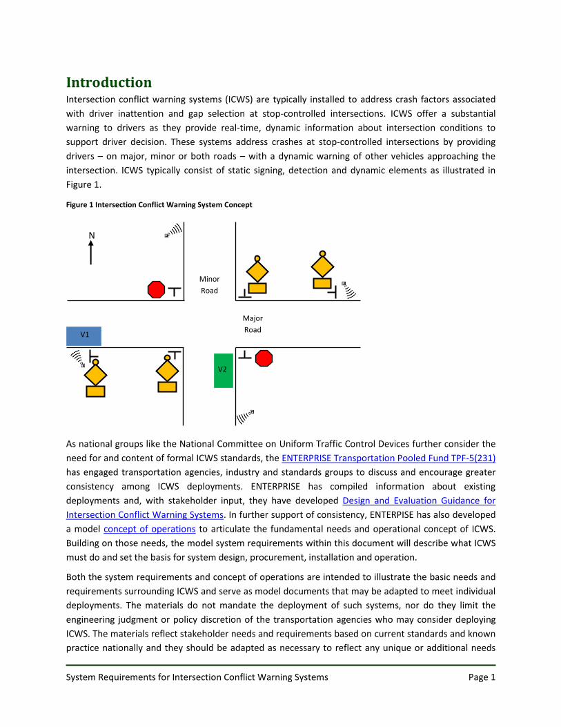
Introduction Intersection conflict warning systems (ICWS) are typically installed to address crash factors associated
with driver inattention and gap selection at stop-controlled intersections. ICWS offer a substantial
warning to drivers as they provide real-time, dynamic information about intersection conditions to
support driver decision. These systems address crashes at stop-controlled intersections by providing
drivers – on major, minor or both roads – with a dynamic warning of other vehicles approaching the
intersection. ICWS typically consist of static signing, detection and dynamic elements as illustrated in
Figure 1.
As national groups like the National Committee on Uniform Traffic Control Devices further consider the
need for and content of formal ICWS standards, the ENTERPRISE Transportation Pooled Fund TPF-5(231)
has engaged transportation agencies, industry and standards groups to discuss and encourage greater
consistency among ICWS deployments. ENTERPRISE has compiled information about existing
deployments and, with stakeholder input, they have developed Design and Evaluation Guidance for
Intersection Conflict Warning Systems. In further support of consistency, ENTERPISE has also developed
a model concept of operations to articulate the fundamental needs and operational concept of ICWS.
Building on those needs, the model system requirements within this document will describe what ICWS
must do and set the basis for system design, procurement, installation and operation.
Both the system requirements and concept of operations are intended to illustrate the basic needs and
requirements surrounding ICWS and serve as model documents that may be adapted to meet individual
deployments. The materials do not mandate the deployment of such systems, nor do they limit the
engineering judgment or policy discretion of the transportation agencies who may consider deploying
ICWS. The materials reflect stakeholder needs and requirements based on current standards and known
practice nationally and they should be adapted as necessary to reflect any unique or additional needs
Major
Road
Minor
Road
V1
N
V2
Figure 1 Intersection Conflict Warning System Concept
System Requirements for Intersection Conflict Warning Systems Page 2
and requirements driven by individual deployments. The remainder of this document presents model
system requirements for ICWS as they are driven by the previously developed concept of operations.
System Requirements System requirements are verifiable details that define what an intersection conflict warning system will
do, how well it will perform or what conditions it must perform under. An important starting point for
developing system requirements is to understand where the systems fit within the ITS architecture. This
section explains how ICWS fit within the National ITS Architecture 7.0 and then presents a series of high-
level and detailed system requirements associated with detection, alerts, placement, operations and
maintenance.
ITS Architecture ICWS are considered part of the Intersection Collision Avoidance User Service in the National ITS
Architecture. Systems within this user service provide vehicle operators with assistance in avoiding
collisions at intersections. The situations addressed include those that arise when vehicles improperly
violate the right-of-way of another vehicle, or when the right-of-way is not clear. The service will provide
warnings of imminent collisions with crossing traffic, as well as warnings of stop control – either a stop
sign or a traffic signal – in the intersection ahead (USDOT, 2012).
Within the physical architecture of the National ITS Architecture, ICWS are primarily addressed under
the Roadway Subsystem; Roadway Intersection Safety Warning Equipment Package and the Roadway
Equipment Coordination Equipment Package; AVSS05-Intersection Safety Warning Service Package and
the AVSS10-Intersection Collision Avoidance Service Package. Table 1 presents a series of high-level
functional requirements as they are presented within the Roadway Intersection Safety Warning
Equipment Package and the Roadway Equipment Coordination Equipment Package of the National ITS
Architecture. The currently applicable requirements have been incorporated into this document.
Table 1 ICWS Functional Requirements from National ITS Architecture
Ro
adw
ay In
ters
ecti
on
Saf
ety
War
nin
g Eq
uip
me
nt
Pac
kage
Functional Requirements
1. The field element shall utilize traffic sensors to monitor vehicles approaching and occupying an intersection.
2. The field element shall monitor the operational state, signal timing, and current phase of the traffic signal (or ICWS).
3. The field element shall monitor road conditions on approaches to, and within, the intersection.
4. The field element shall communicate with approaching vehicles to determine vehicle position, velocity, acceleration, direction, and intended turning movement.
5. The field element shall detect potentially hazardous conditions including impending red-light or stop sign violations and potential conflicts between approaching vehicles.
6. The field element shall provide intersection status and warnings to approaching vehicles using field-vehicle communications.
7. The field element shall update signs or signals to warn the driver of potentially hazardous situations.
System Requirements for Intersection Conflict Warning Systems Page 3
Ro
adw
ay E
qu
ipm
en
t
Co
ord
inat
ion
Eq
uip
me
nt
Pac
kage
Functional Requirements
1. The field element shall include sensors that provide data and status information to other field element devices, without center control.
2. The field element shall include sensors that receive configuration data from other field element devices, without center control.
3. The field element shall include devices that provide data and status information to other field element devices, without center control.
4. The field element shall include devices that receive configuration data from other field element devices, without center control.
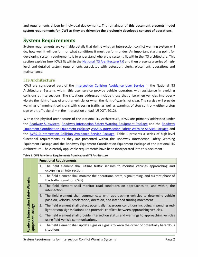
Further illustrating how ICWS fit within the National ITS Architecture, Figure 2 shows the potential
system components and interconnects within the AVSS05-Intersection Safety Warning Service Package.
Based on the deployments to-date, ICWS have not significantly addressed the Vehicle Subsystem
characteristics shaded in Figure 2 or the vehicle-oriented functional requirements shaded in Table 1.
However, as USDOT’s Connected Vehicle Research evolves, ICWS requirements and designs will also
need to evolve and directly address these issues. The requirements identified in this document are
focused on the more prominent roadside infrastructure details in the Roadway Subsystem.
Figure 2 AVSS05-Intersection Safety Warning Service Package Graphic
The information presented in this section should be reviewed, confirmed or modified within the context
of any state or regional ITS architecture that may impact individual ICWS deployments.
High-Level and Detailed System Requirements ICWS are traffic control devices and as such it is important to note that these model requirements are
based on the principles of traffic control devices outlined in the Manual on Uniform Traffic Control

System Requirements for Intersection Conflict Warning Systems Page 4
Devices (MUTCD), Part 1. General, Section 1A.02. The manual states that, “To be effective, a traffic
control device should meet five basic requirements: A. Fulfill a need; B. Command attention; C. Convey a
clear, simple meaning; D. Command respect from road users; and E. Give adequate time for proper
response.” The model ICWS requirements presented in this document have been developed with careful
consideration of design, placement, operation, maintenance and uniformity to maximize the ability of
ICWS to meet these basic requirements as a traffic control device. Vehicle speeds have also been
considered as a significant element affecting the operation of ICWS. For those requirements that are
particularly dependent upon speed, recommended values have been based on the 85th percentile – the
speed at or below which 85 percent of the vehicles travel. The requirements also assume that posted
speeds are accurate based on current speed studies. Finally, these model requirements were developed
with the intent to provide the reasonable and prudent road user with information necessary to
efficiently and lawfully navigate intersections equipped with ICWS.
Many of the requirements are also described in relation to the detection and alert components of an
ICWS. It is important to note that the requirements associated with the alert component are described
to include both the dynamic alert (e.g. flashing beacon) and static sign elements. Although most ICWS
deployments use these physical elements, still others use a fully dynamic message sign to convey both
the sign message and an alert. As such, “alert” is used throughout the requirements to encompass both
elements when they exist separately or as one component in an ICWS deployment.
These system requirements are defined in direct relation to the needs identified in the concept of
operations. They address operational aspects of the system and are noted as such in Table 2. Each of the
high level requirements below was originally translated from stakeholder needs identified in the model
concept of operations. The number references allow for traceability back to those needs and forward to
the detailed system requirements. The first identification number refers to the stakeholder needs as
they were presented in the model concept of operations. The second number is used to track high level
requirements and the third reference number relates to detailed system requirements, where
applicable.
For many of the requirements, special considerations are noted to explain what details were considered
as the requirement was developed or what additional details may need to be considered as the
requirement is further refined for individual deployments. In some cases, the considerations may also
note if a requirement is relevant to a specific type of ICWS deployment – on a median-separated
roadway, for example. These considerations are intended to offer context for many of details noted in
the requirements and to support further review and tailoring to individual deployments as needed. For
any final requirements that result in an exception to current parameters in the MUTCD, requests to
experiment may need to be considered.
System Requirements for Intersection Conflict Warning Systems Page 5
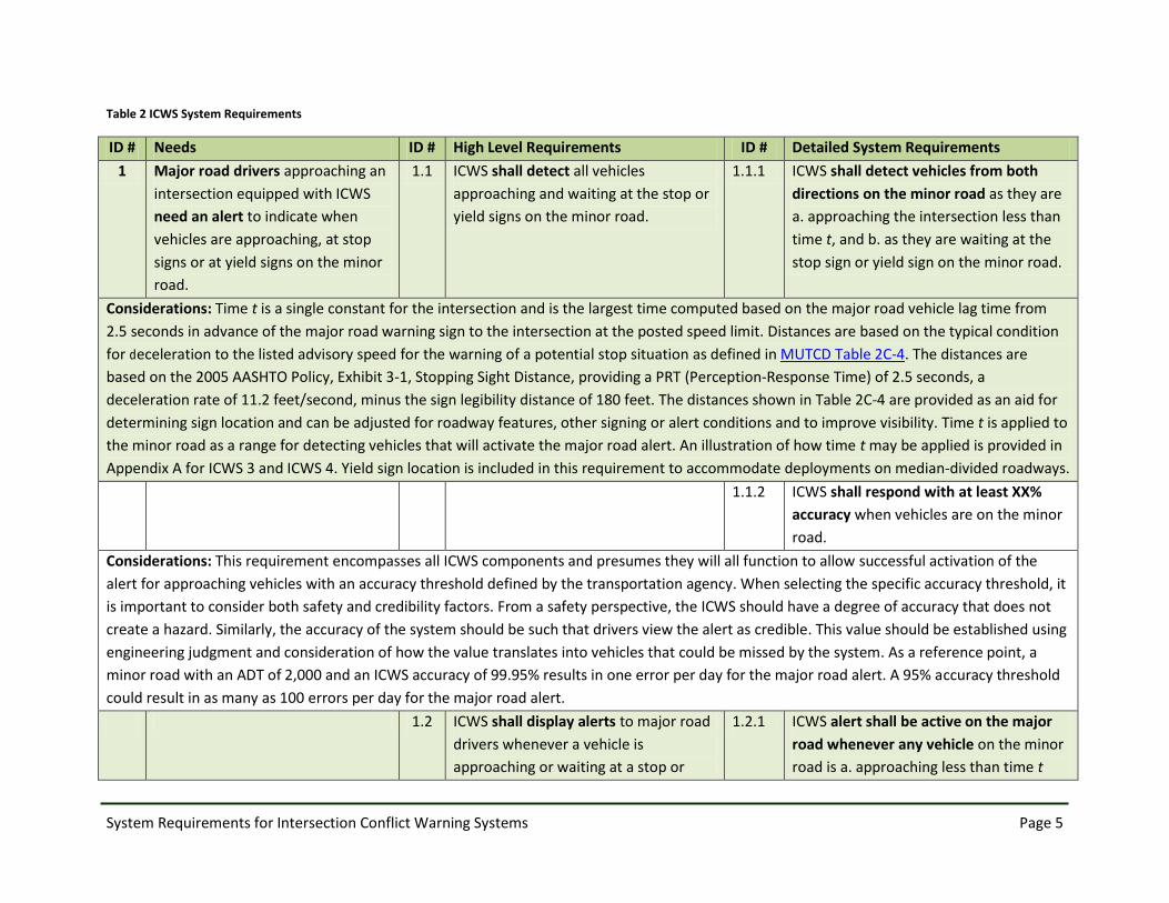
Table 2 ICWS System Requirements
ID # Needs ID # High Level Requirements ID # Detailed System Requirements
1 Major road drivers approaching an
intersection equipped with ICWS
need an alert to indicate when
vehicles are approaching, at stop
signs or at yield signs on the minor
road.
1.1 ICWS shall detect all vehicles
approaching and waiting at the stop or
yield signs on the minor road.
1.1.1 ICWS shall detect vehicles from both
directions on the minor road as they are
a. approaching the intersection less than
time t, and b. as they are waiting at the
stop sign or yield sign on the minor road.
Considerations: Time t is a single constant for the intersection and is the largest time computed based on the major road vehicle lag time from
2.5 seconds in advance of the major road warning sign to the intersection at the posted speed limit. Distances are based on the typical condition
for deceleration to the listed advisory speed for the warning of a potential stop situation as defined in MUTCD Table 2C-4. The distances are
based on the 2005 AASHTO Policy, Exhibit 3-1, Stopping Sight Distance, providing a PRT (Perception-Response Time) of 2.5 seconds, a
deceleration rate of 11.2 feet/second, minus the sign legibility distance of 180 feet. The distances shown in Table 2C-4 are provided as an aid for
determining sign location and can be adjusted for roadway features, other signing or alert conditions and to improve visibility. Time t is applied to
the minor road as a range for detecting vehicles that will activate the major road alert. An illustration of how time t may be applied is provided in
Appendix A for ICWS 3 and ICWS 4. Yield sign location is included in this requirement to accommodate deployments on median-divided roadways.
1.1.2 ICWS shall respond with at least XX%
accuracy when vehicles are on the minor
road.
Considerations: This requirement encompasses all ICWS components and presumes they will all function to allow successful activation of the
alert for approaching vehicles with an accuracy threshold defined by the transportation agency. When selecting the specific accuracy threshold, it
is important to consider both safety and credibility factors. From a safety perspective, the ICWS should have a degree of accuracy that does not
create a hazard. Similarly, the accuracy of the system should be such that drivers view the alert as credible. This value should be established using
engineering judgment and consideration of how the value translates into vehicles that could be missed by the system. As a reference point, a
minor road with an ADT of 2,000 and an ICWS accuracy of 99.95% results in one error per day for the major road alert. A 95% accuracy threshold
could result in as many as 100 errors per day for the major road alert.
1.2 ICWS shall display alerts to major road
drivers whenever a vehicle is
approaching or waiting at a stop or
1.2.1 ICWS alert shall be active on the major
road whenever any vehicle on the minor
road is a. approaching less than time t

System Requirements for Intersection Conflict Warning Systems Page 6
ID # Needs ID # High Level Requirements ID # Detailed System Requirements
yield sign on the minor road. away from the stop sign, or b. waiting at
the stop sign, or c. within the
intersection, or d. waiting at the median
yield sign.
Considerations: Intersection is defined as follows in the MUTCD, Part 1. General, Section 1A.13 Definitions of Headings, Words, and Phrases in
this Manual:
a) The area embraced within the prolongation or connection of the lateral curb lines, or if none, the lateral boundary lines of the roadways
of two highways that join one another at, or approximately at, right angles or the area within which vehicles traveling on different
highways that join at any other angle might come into conflict.
b) The junction of an alley or driveway with a roadway or highway shall not constitute an intersection, unless the roadway or highway at
said junction is controlled by a traffic control device.
c) If a highway includes two roadways that are 30 feet or more apart (see definition of median), then every crossing of each roadway of such
divided highway by an intersecting highway shall be a separate intersection.
d) If both intersecting highways include two roadways that are 30 feet or more apart, then every crossing of any two roadways of such
highways shall be a separate intersection.
The yield sign location is included in this requirement to accommodate deployments on median-divided roadways. Also note that the emphasis
on “any vehicle” within the stated parameters should cause the ICWS alert to be active.
1.2.2 ICWS alert shall be inactive on the major
road whenever there are no vehicles on
the minor road a. approaching less than
time t away from the stop sign, or b.
waiting at the stop sign, or c. within the
intersection, or d. waiting at the median
yield sign.
Considerations: Yield sign location is included in this requirement to accommodate deployments on median-divided roadways. Also note that the
emphasis on “no vehicles” within the stated parameters should cause the ICWS alert to be inactive.
1.2.3 ICWS alert activation and deactivation
on the major road shall be within ±0.5
seconds of time t.
System Requirements for Intersection Conflict Warning Systems Page 7
ID # Needs ID # High Level Requirements ID # Detailed System Requirements
Considerations: This requirement describes the degree of accuracy that is tolerated for alert activation on the major road at the beginning of
time t and deactivation at the end of time t as vehicles approach the stop sign on the minor road.
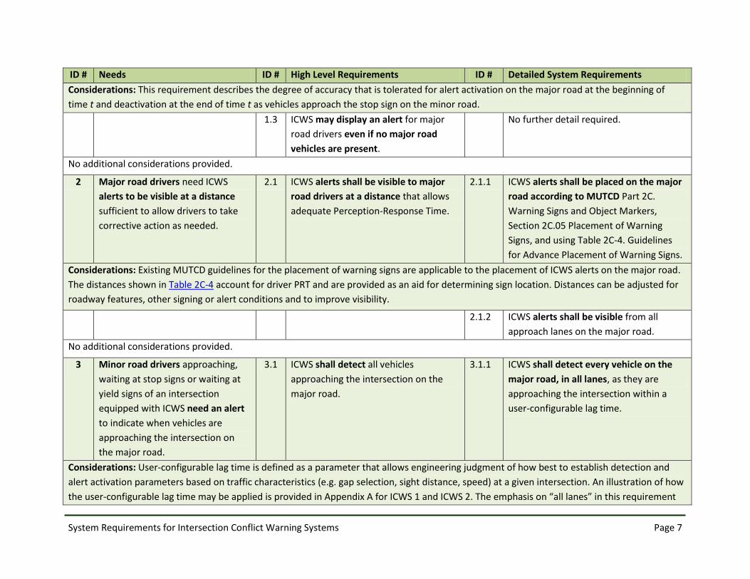
1.3 ICWS may display an alert for major
road drivers even if no major road
vehicles are present.
No further detail required.
No additional considerations provided.
2 Major road drivers need ICWS
alerts to be visible at a distance
sufficient to allow drivers to take
corrective action as needed.
2.1 ICWS alerts shall be visible to major
road drivers at a distance that allows
adequate Perception-Response Time.
2.1.1 ICWS alerts shall be placed on the major
road according to MUTCD Part 2C.
Warning Signs and Object Markers,
Section 2C.05 Placement of Warning
Signs, and using Table 2C-4. Guidelines
for Advance Placement of Warning Signs.
Considerations: Existing MUTCD guidelines for the placement of warning signs are applicable to the placement of ICWS alerts on the major road.
The distances shown in Table 2C-4 account for driver PRT and are provided as an aid for determining sign location. Distances can be adjusted for
roadway features, other signing or alert conditions and to improve visibility.
2.1.2 ICWS alerts shall be visible from all
approach lanes on the major road.
No additional considerations provided.
3 Minor road drivers approaching,
waiting at stop signs or waiting at
yield signs of an intersection
equipped with ICWS need an alert
to indicate when vehicles are
approaching the intersection on
the major road.
3.1 ICWS shall detect all vehicles
approaching the intersection on the
major road.
3.1.1 ICWS shall detect every vehicle on the
major road, in all lanes, as they are
approaching the intersection within a
user-configurable lag time.
Considerations: User-configurable lag time is defined as a parameter that allows engineering judgment of how best to establish detection and
alert activation parameters based on traffic characteristics (e.g. gap selection, sight distance, speed) at a given intersection. An illustration of how
the user-configurable lag time may be applied is provided in Appendix A for ICWS 1 and ICWS 2. The emphasis on “all lanes” in this requirement

System Requirements for Intersection Conflict Warning Systems Page 8
ID # Needs ID # High Level Requirements ID # Detailed System Requirements
may be refined to specify a number of through lanes or turning lanes for multi-lane roadways.
3.1.2 ICWS shall detect vehicles on the major
road from both directions as they are
approaching the intersection within a
user-configurable lag time.
No additional considerations provided.
3.1.3 ICWS shall respond with at least XX%
accuracy when vehicles are on the major
road.
Considerations: This requirement encompasses all ICWS components and presumes they will all function to allow successful activation of the
alert for approaching vehicles with an accuracy threshold defined by the transportation agency. When selecting the specific accuracy threshold, it
is important to consider both safety and credibility factors. From a safety perspective, the ICWS should have a degree of accuracy that does not
create a hazard. This is potentially more important for the minor road alert as drivers may be relying on the ICWS in conjunction with stop sign.
Similarly, the accuracy of the system should be such that drivers view the alert as credible. This value should be established using engineering
judgment and consideration of how the value translates into vehicles that could be missed by the system. As a reference point, a major roadway
with an ADT of 6,000 and an ICWS accuracy of 99.95% results in three errors per day for the minor road alert. A 95% accuracy threshold could
result in as many as 300 errors per day for the minor road alert.
3.2 ICWS shall display alerts to minor road
drivers whenever vehicles approach
the intersection on the major road.
3.2.1 ICWS alert shall be active on the minor
road whenever any vehicle on the major
road a. is approaching less than a user-
configurable lag time away from the
intersection, or b. is within the
intersection.
Considerations: Note that the emphasis on “any vehicle” within the stated parameters should cause the ICWS alert to be active.
3.2.2 ICWS alert shall be inactive on the minor
road whenever there are no vehicles
approaching less than a user-configurable
lag time away from the intersection on
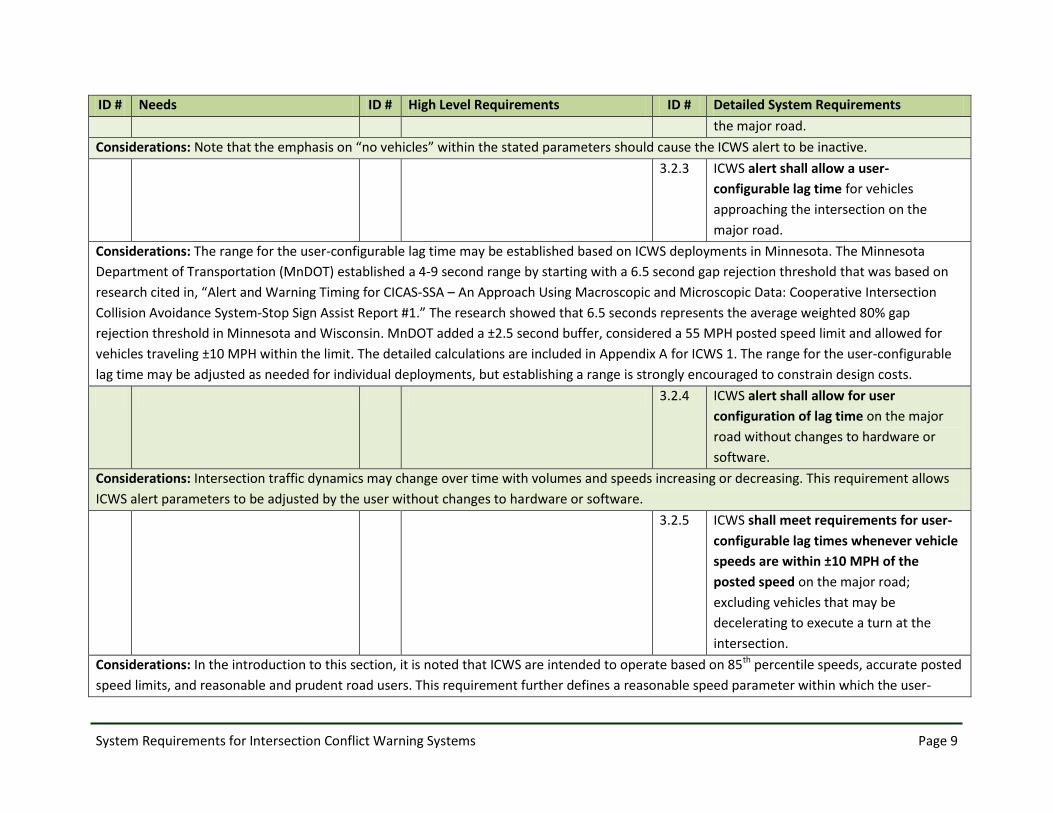
System Requirements for Intersection Conflict Warning Systems Page 9
ID # Needs ID # High Level Requirements ID # Detailed System Requirements
the major road.
Considerations: Note that the emphasis on “no vehicles” within the stated parameters should cause the ICWS alert to be inactive.
3.2.3 ICWS alert shall allow a user-
configurable lag time for vehicles
approaching the intersection on the
major road.
Considerations: The range for the user-configurable lag time may be established based on ICWS deployments in Minnesota. The Minnesota
Department of Transportation (MnDOT) established a 4-9 second range by starting with a 6.5 second gap rejection threshold that was based on
research cited in, “Alert and Warning Timing for CICAS-SSA – An Approach Using Macroscopic and Microscopic Data: Cooperative Intersection
Collision Avoidance System-Stop Sign Assist Report #1.” The research showed that 6.5 seconds represents the average weighted 80% gap
rejection threshold in Minnesota and Wisconsin. MnDOT added a ±2.5 second buffer, considered a 55 MPH posted speed limit and allowed for
vehicles traveling ±10 MPH within the limit. The detailed calculations are included in Appendix A for ICWS 1. The range for the user-configurable
lag time may be adjusted as needed for individual deployments, but establishing a range is strongly encouraged to constrain design costs.
3.2.4 ICWS alert shall allow for user
configuration of lag time on the major
road without changes to hardware or
software.
Considerations: Intersection traffic dynamics may change over time with volumes and speeds increasing or decreasing. This requirement allows
ICWS alert parameters to be adjusted by the user without changes to hardware or software.
3.2.5 ICWS shall meet requirements for user-
configurable lag times whenever vehicle
speeds are within ±10 MPH of the
posted speed on the major road;
excluding vehicles that may be
decelerating to execute a turn at the
intersection.
Considerations: In the introduction to this section, it is noted that ICWS are intended to operate based on 85th percentile speeds, accurate posted
speed limits, and reasonable and prudent road users. This requirement further defines a reasonable speed parameter within which the user-
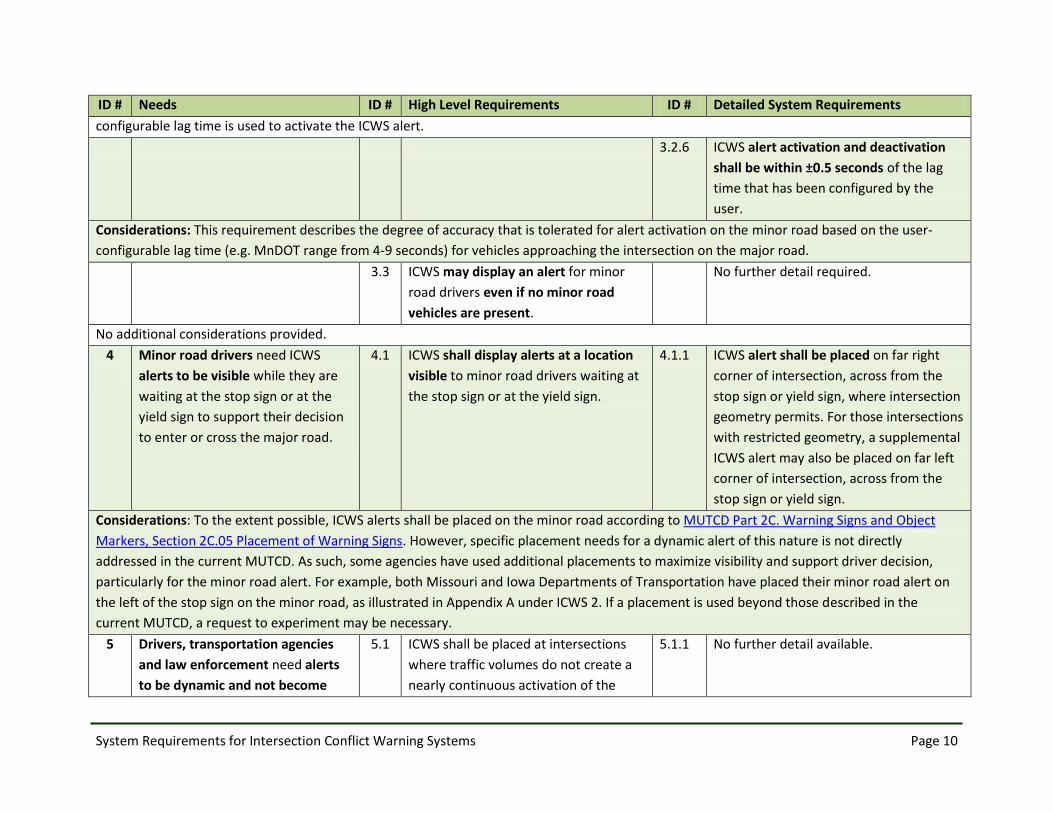
System Requirements for Intersection Conflict Warning Systems Page 10
ID # Needs ID # High Level Requirements ID # Detailed System Requirements
configurable lag time is used to activate the ICWS alert.
3.2.6 ICWS alert activation and deactivation
shall be within ±0.5 seconds of the lag
time that has been configured by the
user.
Considerations: This requirement describes the degree of accuracy that is tolerated for alert activation on the minor road based on the user-
configurable lag time (e.g. MnDOT range from 4-9 seconds) for vehicles approaching the intersection on the major road.
3.3 ICWS may display an alert for minor
road drivers even if no minor road
vehicles are present.
No further detail required.
No additional considerations provided.
4
Minor road drivers need ICWS
alerts to be visible while they are
waiting at the stop sign or at the
yield sign to support their decision
to enter or cross the major road.
4.1 ICWS shall display alerts at a location
visible to minor road drivers waiting at
the stop sign or at the yield sign.
4.1.1 ICWS alert shall be placed on far right
corner of intersection, across from the
stop sign or yield sign, where intersection
geometry permits. For those intersections
with restricted geometry, a supplemental
ICWS alert may also be placed on far left
corner of intersection, across from the
stop sign or yield sign.
Considerations: To the extent possible, ICWS alerts shall be placed on the minor road according to MUTCD Part 2C. Warning Signs and Object
Markers, Section 2C.05 Placement of Warning Signs. However, specific placement needs for a dynamic alert of this nature is not directly
addressed in the current MUTCD. As such, some agencies have used additional placements to maximize visibility and support driver decision,
particularly for the minor road alert. For example, both Missouri and Iowa Departments of Transportation have placed their minor road alert on
the left of the stop sign on the minor road, as illustrated in Appendix A under ICWS 2. If a placement is used beyond those described in the
current MUTCD, a request to experiment may be necessary.
5 Drivers, transportation agencies
and law enforcement need alerts
to be dynamic and not become
5.1 ICWS shall be placed at intersections
where traffic volumes do not create a
nearly continuous activation of the
5.1.1 No further detail available.

System Requirements for Intersection Conflict Warning Systems Page 11
ID # Needs ID # High Level Requirements ID # Detailed System Requirements
nearly continuous so as to lose
impact.
alert.
Considerations: A range of entering traffic volumes for effective operation of ICWS is not yet known. Understanding that a nearly continuous
alert activation will diminish the dynamic nature of the alert, engineering judgment is needed to determine when volumes may be too high for
effective deployments. For example, if ICWS is installed to address an off-peak crash problem that does not result in a nearly continuous alert, it
may be acceptable for a nearly continuous alert during the peak period. Additional safety effectiveness studies are being conducted by the
Evaluation of Low Cost Safety Improvements Transportation Pooled Fund TPF-5(099) and this will offer further insight on optimal volume
conditions for ICWS deployment.
6 Drivers, transportation agencies
and law enforcement need ICWS
alerts to be easily understood.
6.1 To the extent possible, ICWS shall
follow recommended design practices
described in “Design and Evaluation
Guidance for Intersection Conflict
Warning Systems” authored by the
ENTERPRISE Transportation Pooled
Fund program.
6.1.1 ICWS should be designed using the
placement, sign combinations and
message sets described for ICWS 1-4 in
“Design and Evaluation Guidance for
Intersection Conflict Warning Systems.”
Considerations: Ideal placement, sign combinations and message sets are not yet known for ICWS. The Traffic Control Devices Transportation
Pooled Fund TPF-5(065) will be studying this issue based on the deployments captured in “Design and Evaluation Guidance for Intersection
Conflict Warning Systems” as it has been developed by ENTERPRISE and endorsed by the AASHTO Subcommittee on Traffic Engineering (SCOTE).
This requirement references the guidance document to, at a minimum, prevent future deployments from using additional new placements, sign
combinations or message sets.
7 Drivers, transportation agencies,
law enforcement and industry
need ICWS alerts and signage to be
uniform throughout the United
States, to the extent possible.
7.1 ICWS shall have similar sign
combinations and message sets across
jurisdictions.
7.1.1 ICWS shall be designed in accordance
with MUTCD Part 2C. Warning Signs and
Object Markers, Section 2C.03 Design of
Warning Signs and Section 2C.04 Size of
Warning Signs.
Considerations: As noted in the considerations for 6.1, the additional research being conducted by the Traffic Control Devices Transportation
Pooled Fund TPF-5(065) will further clarify which sign combinations and message sets are most effective. The National Committee on Uniform
Traffic Control Devices will then consider if the research results merit modifications to the MUTCD.
8 Drivers who are distracted need 8.1 ICWS alerts shall be conspicuous. 8.1.1 ICWS alert shall conform to MUTCD Part

System Requirements for Intersection Conflict Warning Systems Page 12
ID # Needs ID # High Level Requirements ID # Detailed System Requirements
ICWS alerts to be of a nature that
will capture their attention.
2A. General, Section 2A.07
Retroreflectivity and Illumination for sign
sheeting materials and LED brightness.
Considerations: This requirement applies to ICWS that may consist of a flashing beacon and static sign combination, as well as those ICWS that
may of a dynamic message sign to convey alerts and sign messaging.
9 Transportation agencies and law
enforcement need ICWS alerts to
provide supplemental warning
that does not contradict or
override the regulatory signs at the
intersection.
9.1 ICWS shall function as a warning sign
as defined in MUTCD Part 2C. Warning
Signs and Object Markers, Section
2C.01 Function of Warning Signs and
Section 2C.02 Application of Warning
Signs.
No further detail required.
No additional considerations provided.
10 Drivers, transportation agencies
and law enforcement need ICWS
to be operational whenever
vehicles approach the intersection.
10.1 ICWS shall operate continuously 24x7,
365 days per year, with minimal service
interruption.
10.1.1 ICWS shall operate in a continuous mode
under normal conditions with service
interruption occurring no more
frequently than once every six months
on average, excluding utility power
service failure.
Considerations: The emphasis on “once every six months” is a suggested performance parameter based on deployment experience in Minnesota
and it is intended to give manufacturers an indication of expected system robustness. This parameter should be adjusted as needed to match
similar performance parameters within an agency. This is a performance oriented requirement.
10.1.2 ICWS shall operate in a continuous mode
under normal conditions with service
interruptions lasting no longer than the
time prescribed by agency maintenance
procedures, excluding utility power
service failure.
Considerations: Each agency should establish maintenance priorities for ICWS that specify a maximum duration for service interruptions. It is

System Requirements for Intersection Conflict Warning Systems Page 13
ID # Needs ID # High Level Requirements ID # Detailed System Requirements
suggested that an agency’s allowable service interruptions for traffic signals be referenced as a baseline. According to the 2012 National Traffic
Signal Report Card and the noteworthy findings on traffic signal maintenance, the results showed that 80 percent of agencies have policies and
processes to provide a technician at an intersection where a critical (traffic signal) malfunction is reported within four hours during business hours
and within eight hours outside of regular business hours. This is a performance oriented requirement.
10.1.3 ICWS components shall conform to
NEMA TS 2-2003 environmental
requirements.
No additional considerations provided.
10.1.4 ICWS alert shall conform to applicable
NEMA TS 4-2005 standards for the
hardware and functional characteristics
of electronically controlled dynamic
message signs.
Considerations: This requirement is only applicable if a dynamic message sign is used in place of static signing and other dynamic alert elements.
Some elements of NEMA TS 4-2005 may not be applicable for ICWS. For example, some of the requirements associated with larger overhead
dynamic message signs (e.g. walk-in access) will not be relevant to ICWS as a smaller roadside dynamic message sign.
10.1.5 ICWS shall be connected to reliable
electrical service.
Considerations: This requirement specifies “reliable electrical service” because of the performance expectations in 10.1.1 and 10.1.2. This
requirement may be modified to specify utility power service or to allow battery or solar power options but the parameters in 10.1.1 and 10.1.2
may then also need to be modified to reflect comparable performance expectations. The selection of utility power service or battery/solar power
should be made based on site characteristics and performance expectations.
10.1.6 ICWS system communication
components shall comply with Federal
Communications Commission (FCC)
emission requirements. The system shall
be able to meet needed FCC approvals
when design is complete.

System Requirements for Intersection Conflict Warning Systems Page 14
ID # Needs ID # High Level Requirements ID # Detailed System Requirements
Considerations: This requirement is only applicable if connections between ICWS components are wireless.
10.1.7 ICWS shall meet the requirements of UL
508 “Standard for Industrial Control
Equipment” and UL 48 “Standard for
Electric Signs” , January 28th 1999
Edition, and the requirements of the
current edition of the National Electrical
Code by being listed by a Nationally
Recognized Testing Laboratory (NRTL) as
safe for its intended purpose.
Considerations: There may be additional or other state-level design requirements for electrical components of ICWS.
10.1.8 ICWS shall restart automatically upon
restoration of power following an event
that causes loss of power to the system.
No additional considerations provided.
10.2 ICWS shall not depend on
communication with external systems
to operate.
No further detail required.
Considerations: If field to center communication is desirable for ICWS operation, this high level requirement should be modified and
requirements added to reflect applicable National Transportation Communications for ITS Protocol (NTCIP) standards for such field to center
communication.
11 Drivers, transportation agencies,
law enforcement and industry
need an ICWS malfunction to be
readily and easily differentiated
from an ICWS that is inactive due to
lack of conflicting traffic.
11.1 ICWS shall display a visible indication
of malfunction.
11.1.1 ICWS shall detect any system component
malfunction and initiate a failure mode.
No additional considerations provided.

System Requirements for Intersection Conflict Warning Systems Page 15
ID # Needs ID # High Level Requirements ID # Detailed System Requirements
11.1.2 ICWS shall display indication of
malfunction within one minute of
system recognition.
Considerations: This requirement may be more critical for minor road alerts illustrated in ICWS 1 and 2 where drivers could more closely
associate ICWS alerts with their response to the regulatory STOP sign.
11.1.3 ICWS shall display an indication of
malfunction in a failsafe manner.
Considerations: Depending on complexity of the ICWS design, the failsafe indication may be visibly different than any other indication from the
system or it may indicate a false positive condition.
11.1.4 ICWS indication of malfunction shall be
maintained by the system until the
system is reset, excluding power failure.
Considerations: Assuming the malfunction is not caused by power failure and power is sustained to the ICWS, this requirement forces the system
to maintain the indication of malfunction until it is addressed and the system is physically reset.
11.1.5 ICWS indication of malfunction shall be
maintained by system through loss of
power for up to the time prescribed by
agency maintenance procedures.
Considerations: Depending on the alert used for individual deployments, this requirement could necessitate a battery backup to maintain the
indication of malfunction for an agency specified duration. For example, if a flashing beacon is used as the alert, a malfunction could trigger
continuous activation of the beacon. If power loss is the cause of the malfunction, a backup battery would be necessary to maintain the indication
as required.
12 Drivers, transportation agencies
and law enforcement need ICWS
not to obstruct view of
intersection, other vehicles or
regulatory signs.
12.1 ICWS shall not obstruct any drivers’
view of the roadway, other vehicles or
regulatory signs at the intersection.
No further detail required.
No additional considerations provided.
System Requirements for Intersection Conflict Warning Systems Page 16
ID # Needs ID # High Level Requirements ID # Detailed System Requirements
13 Drivers, transportation agencies,
law enforcement and industry
need ICWS components to be
crashworthy in the event they are
impacted by errant vehicles.
13.1 ICWS shall meet MUTCD Part 2A.
General, Section 2A.21 Posts and
Mountings standard and AASHTO
Specification for Structural Supports
for Highway Signs, Luminaires and
Traffic Signals for crashworthiness.
No further detail required.
No additional considerations provided.
14 Transportation agencies need a
maintenance process that can be
followed to repair or replace ICWS
components in context with
priorities for repairing all other
traffic control devices.
14.1 ICWS shall consist of materials as
specified in Standard Specifications for
Construction of Roads and Bridges on
Federal Highway Projects, Section 718
Traffic Signing and Marking Material.
No further detail required.
Considerations: Additional information from state or local transportation agency construction specifications may need to be cited here.
14.2 ICWS shall be installed as specified in
Standard Specifications for
Construction of Roads and Bridges on
Federal Highway Projects, Section 633
Permanent Traffic Control and Section
636 Signal, Lighting and Electrical
Systems.
No further detail required.
Considerations: Additional information from state or local transportation agency construction specifications may need to be cited here.
15 Transportation agencies need
ICWS to provide information
regarding system performance.
15.1 ICWS shall collect and retain data
about system performance that
indicates when and what components
have failed or may be operating in less
than optimal states.
15.1.1 ICWS shall maintain an internal record of
detection and power failures and a
corresponding time/date stamp for when
the failure began and ended.
No additional considerations provided.

System Requirements for Intersection Conflict Warning Systems Page 17
ID # Needs ID # High Level Requirements ID # Detailed System Requirements
15.1.2 ICWS shall maintain an internal record of
individual system activations with a
time/date stamp during a 96 hour period.
Considerations: The 96-hour timeframe is suggested for this requirement to allow time for reviewing performance data over several days,
particularly a holiday weekend, or for law enforcement to access data that may be applicable to a traffic incident. This timeframe should be
considered within the context of each agency’s needs and adjusted as necessary.
15.1.3 ICWS shall maintain an internal record of
individual vehicle detections with a
time/date stamp during a 96 hour period.
Considerations: The 96-hour timeframe is suggested for this requirement to allow time for reviewing performance data over several days,
particularly a holiday weekend, or for law enforcement to access data that may be applicable to a traffic incident. This timeframe should be
considered within the context of each agency’s needs and adjusted as necessary.
16 Transportation agencies and
industry need installation,
operational and maintenance
documentation for ICWS.
16.1 ICWS shall be manufactured with
installation, operational and
maintenance documentation.
No further detail required.
No additional considerations provided.
17 Transportation agencies need to
be able to maintain ICWS with
minimal impact on traffic.
17.1 ICWS components shall be physically
accessible for maintenance with one
transportation agency vehicle and a 1-2
person crew within the right of way.
No further detail required.
No additional considerations provided.
18 Transportation agencies and law
enforcement need to be able to
manually activate the malfunction
mode during maintenance or repair
situations.
18.1 ICWS shall allow manual activation of
the malfunction mode accessible by
police panel key.
No further detail required.
No additional considerations provided.

System Requirements for Intersection Conflict Warning Systems Page 18
ID # Needs ID # High Level Requirements ID # Detailed System Requirements
19 Transportation agencies need
ICWS to be cost effective.
19.1
ICWS shall be scalable and
reconfigurable to allow major road
only, minor road only or major/minor
road alerts.
19.1.1 ICWS shall allow a minor road only
system to be added to a major road
system and provide combined alert to
both major and minor road drivers.
No additional considerations provided.
19.1.2 ICWS shall allow a major road only
system to be added to a minor road
system and provide combined alerts to
both major and minor road drivers.
No additional considerations provided.
19.1.3 ICWS shall allow the minor or major road
alert to be removed from a combined
major and minor road alert and provide
alerts to only the major or minor road
drivers.
No additional considerations provided.
20 Transportation agencies need to
understand ICWS safety impacts
on total crash reduction, target
(right angle) crash reduction and
reduction in crash severity.
20.1 ICWS shall have documentation
referencing its safety effectiveness
under specific deployment conditions.
No further detail required.
No additional considerations provided.
System Requirements for Intersection Conflict Warning Systems Page A-1
Appendix A: ICWS 1-4, Layouts for Active/Inactive Alert States
System Requirements for Intersection Conflict Warning Systems Page A-2
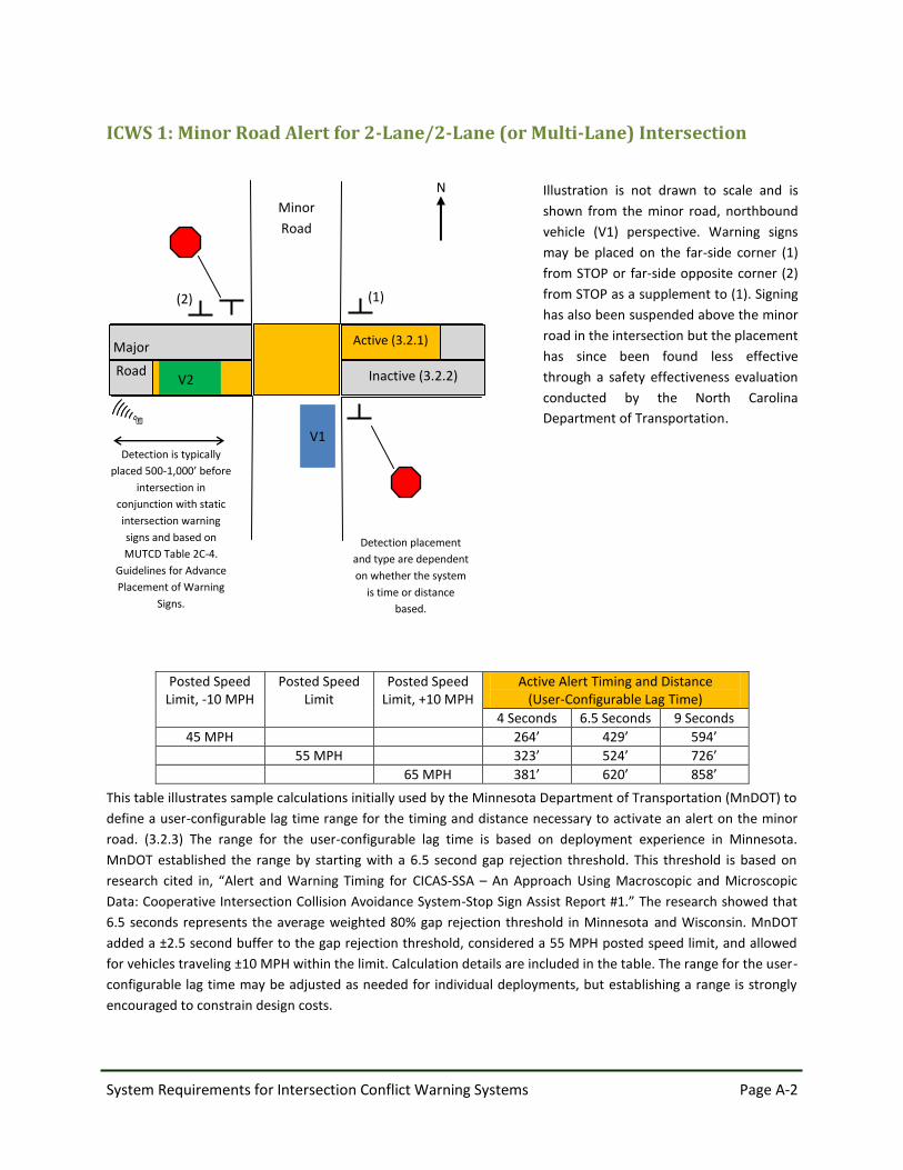
ICWS 1: Minor Road Alert for 2-Lane/2-Lane (or Multi-Lane) Intersection
Posted Speed Limit, -10 MPH
Posted Speed Limit
Posted Speed Limit, +10 MPH
Active Alert Timing and Distance (User-Configurable Lag Time)
4 Seconds 6.5 Seconds 9 Seconds
45 MPH 264’ 429’ 594’
55 MPH 323’ 524’ 726’
65 MPH 381’ 620’ 858’
This table illustrates sample calculations initially used by the Minnesota Department of Transportation (MnDOT) to
define a user-configurable lag time range for the timing and distance necessary to activate an alert on the minor
road. (3.2.3) The range for the user-configurable lag time is based on deployment experience in Minnesota.
MnDOT established the range by starting with a 6.5 second gap rejection threshold. This threshold is based on
research cited in, “Alert and Warning Timing for CICAS-SSA – An Approach Using Macroscopic and Microscopic
Data: Cooperative Intersection Collision Avoidance System-Stop Sign Assist Report #1.” The research showed that
6.5 seconds represents the average weighted 80% gap rejection threshold in Minnesota and Wisconsin. MnDOT
added a ±2.5 second buffer to the gap rejection threshold, considered a 55 MPH posted speed limit, and allowed
for vehicles traveling ±10 MPH within the limit. Calculation details are included in the table. The range for the user-
configurable lag time may be adjusted as needed for individual deployments, but establishing a range is strongly
encouraged to constrain design costs.
Illustration is not drawn to scale and is
shown from the minor road, northbound
vehicle (V1) perspective. Warning signs
may be placed on the far-side corner (1)
from STOP or far-side opposite corner (2)
from STOP as a supplement to (1). Signing
has also been suspended above the minor
road in the intersection but the placement
has since been found less effective
through a safety effectiveness evaluation
conducted by the North Carolina
Department of Transportation.
Detection placement
and type are dependent
on whether the system
is time or distance
based.
N
(2) (1)
Minor
Road
Detection is typically
placed 500-1,000’ before
intersection in
conjunction with static
intersection warning
signs and based on
MUTCD Table 2C-4.
Guidelines for Advance
Placement of Warning
Signs.
V1
Inactive (3.2.2)
Active (3.2.1)
Major
Road V2

System Requirements for Intersection Conflict Warning Systems Page A-3
ICWS 2: Minor Road Alert for 2-Lane/Multi-Lane Median Separated
Intersection
Refer to ICWS 1 for details on the sample calculations for the active alert timing and distance (user-configurable lag
time). (3.2.3)
Illustration is not drawn to scale and is
shown from the minor road, northbound
vehicle (V1) perspective. There is a set of
two warning signs for this layout. The first
sign may be placed on the far-side
opposite corner from STOP (1a) and the
second sign may be placed on the far side
corner from YIELD (1b). Signing has also
been placed left from STOP (2a) and on
the far side corner from YIELD (2b) but
this placement may require a request to
experiment. Other placements have
involved signing suspended above the
minor road at the intersection but this
placement has since been found less
effective through a safety effectiveness
evaluation conducted by the North
Carolina Department of Transportation.
(2a)
(1b, 2b)
N
Major
Road
Minor
Road
Detection is typically
placed 500-1,000’ before
intersection in
conjunction with static
intersection warning
signs and based on
MUTCD Table 2C-4.
Guidelines for Advance
Placement of Warning
Signs.
Median
V1
Detection placement
and type are dependent
on whether the system
is time or distance
based.
Active (3.2.1)
Inactive (3.2.2)
(1a)
V2
System Requirements for Intersection Conflict Warning Systems Page A-4
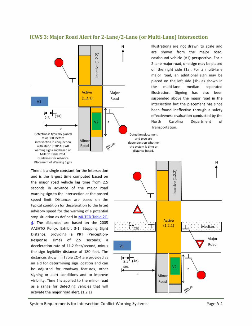
ICWS 3: Major Road Alert for 2-Lane/2-Lane (or Multi-Lane) Intersection
Illustrations are not drawn to scale and
are shown from the major road,
eastbound vehicle (V1) perspective. For a
2-lane major road, one sign may be placed
on the right side (1a). For a multi-lane
major road, an additional sign may be
placed on the left side (1b) as shown in
the multi-lane median separated
illustration. Signing has also been
suspended above the major road in the
intersection but the placement has since
been found ineffective through a safety
effectiveness evaluation conducted by the
North Carolina Department of
Transportation.
Time t is a single constant for the intersection
and is the largest time computed based on
the major road vehicle lag time from 2.5
seconds in advance of the major road
warning sign to the intersection at the posted
speed limit. Distances are based on the
typical condition for deceleration to the listed
advisory speed for the warning of a potential
stop situation as defined in MUTCD Table 2C-
4. The distances are based on the 2005
AASHTO Policy, Exhibit 3-1, Stopping Sight
Distance, providing a PRT (Perception-
Response Time) of 2.5 seconds, a
deceleration rate of 11.2 feet/second, minus
the sign legibility distance of 180 feet. The
distances shown in Table 2C-4 are provided as
an aid for determining sign location and can
be adjusted for roadway features, other
signing or alert conditions and to improve
visibility. Time t is applied to the minor road
as a range for detecting vehicles that will
activate the major road alert. (1.2.1)
2.5 sec
Active (1.2.1)
N
Major
Road
Minor
Road
Median
Inac
tive
(1
.2.2
)
(1a)
t
V1
V2 t
(1b)
Detection is typically placed at or 500’ before
intersection in conjunction with static STOP AHEAD
warning signs and based on MUTCD Table 2C-4.
Guidelines for Advance Placement of Warning Signs
Detection placement and type are
dependent on whether the system is time or
distance based.
t
(1a) 2.5
sec t
N
Major
Road V1
Active
(1.2.1) In
acti
ve (
1.2
.2)
Minor Road
V2

System Requirements for Intersection Conflict Warning Systems Page A-5
ICWS 4: Major and Minor Road Alert for 2-Lane/2-Lane (or Multi-Lane)
Intersection
Refer to ICWS 1 and ICWS 3 for details on the calculations of the active alert timing and distance (user-configurable
lag time and time t) associated with both the major and minor road alerts. (1.2.1) (3.2.3)
Illustration is not drawn to scale and is
shown from the major road, eastbound
vehicle (V1) perspective. For a 2-lane
major road, one sign may be placed on
the right side (1a). For a multi-lane major
road, an additional sign may be placed on
the left side (1b). Warning signs for the
minor road may be placed left from STOP
(2), on the far-side opposite corner (3)
from STOP, OR on the far-side corner (4)
from STOP. Signing has also been
suspended above the intersection but the
placement has since been found less
effective through a safety effectiveness
evaluation conducted by the North
Carolina Department of Transportation.
N
(3) (1b)
(1a) (2)
(4)
Detection is typically placed
at or 500’ before
intersection in conjunction
with static STOP AHEAD
warning signs and based on
MUTCD Table 2C-4.
Guidelines for Advance
Placement of Warning Signs
Detection placement
and type are
dependent on whether
the system is time or
distance based.
In
acti
ve (
1.2
.2)
Act
ive
(1.2
.1)
Active or Inactive (1.2.3, 3.2.2)
Inactive (3.2.2)
Active (3.2.1)
Minor Road
V2
V1 Major Road