system overview burner control fa1 - lamtec · system overview burner control fa1. 2 lamtec |...
TRANSCRIPT
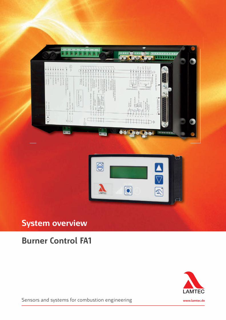
www.lamtec.deSensors and systems for combustion engineering
System overview
Burner Control FA1
2
LAMTEC | Burner Control | FA1
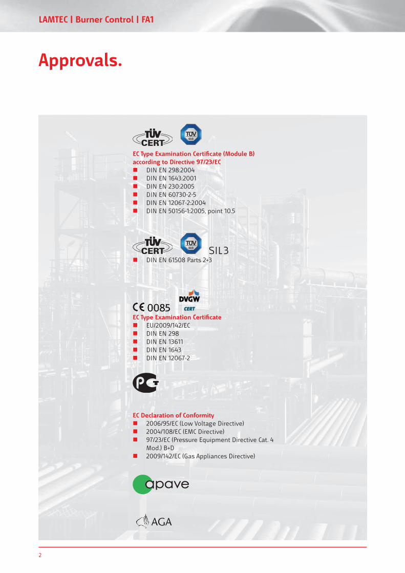
Approvals.
EC Declaration of Conformity 2006/95/EC (Low Voltage Directive) 2004/108/EC (EMC Directive) 97/23/EC (Pressure Equipment Directive Cat. 4
Mod.) B+D 2009/142/EC (Gas Appliances Directive)
EC Type Examination Certifi cate EU/2009/142/EC DIN EN 298 DIN EN 13611 DIN EN 1643 DIN EN 12067-2
EC Type Examination Certifi cate0085
EC Type Examination Certifi cate (Module B) according to Directive 97/23/EC
DIN EN 298:2004 DIN EN 1643:2001 DIN EN 230:2005 DIN EN 60730-2-5 DIN EN 12067-2:2004 DIN EN 50156-1:2005, point 10.5
DIN EN 61508 Parts 2+3SIL 3
www.lamtec.de 3
An e� cientsolution for burner management:LAMTEC Burner Control FA1.
Compact, ready-to-use and universally compatible:
The LAMTEC Burner Control FA1: the ideal solution for cost-e� ective
burner control.
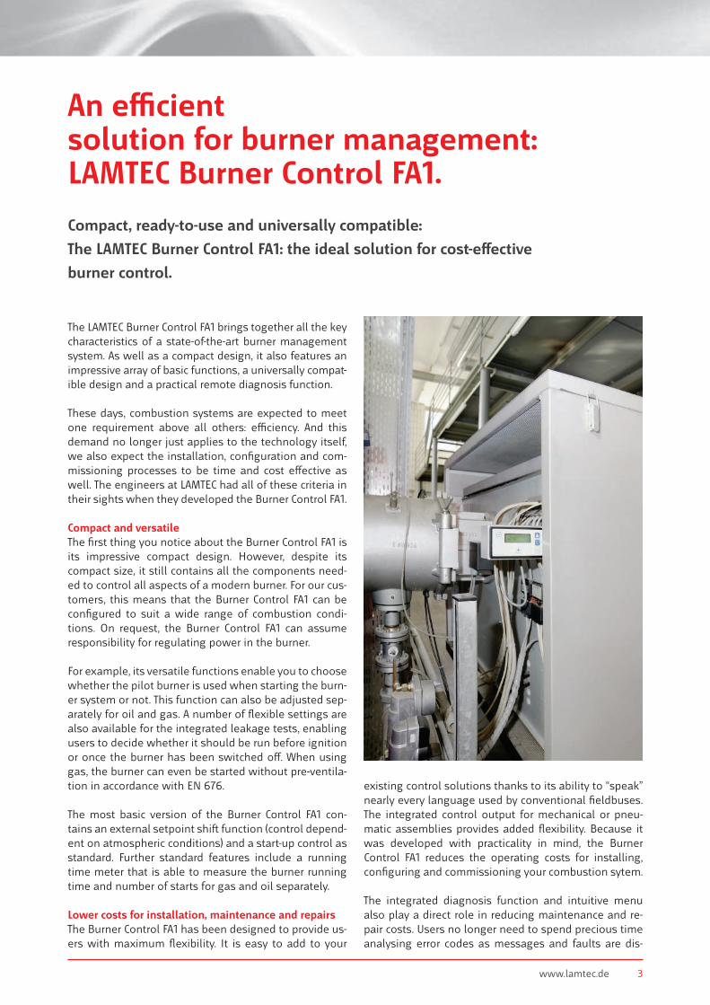
The LAMTEC Burner Control FA1 brings together all the key characteristics of a state-of-the-art burner management system. As well as a compact design, it also features an impressive array of basic functions, a universally compat-ible design and a practical remote diagnosis function.
These days, combustion systems are expected to meet one requirement above all others: e� ciency. And this demand no longer just applies to the technology itself, we also expect the installation, confi guration and com-missioning processes to be time and cost e� ective as well. The engineers at LAMTEC had all of these criteria in their sights when they developed the Burner Control FA1.
Compact and versatileThe fi rst thing you notice about the Burner Control FA1 is its impressive compact design. However, despite its compact size, it still contains all the components need-ed to control all aspects of a modern burner. For our cus-tomers, this means that the Burner Control FA1 can be confi gured to suit a wide range of combustion condi-tions. On request, the Burner Control FA1 can assume responsibility for regulating power in the burner.
For example, its versatile functions enable you to choose whether the pilot burner is used when starting the burn-er system or not. This function can also be adjusted sep-arately for oil and gas. A number of fl exible settings are also available for the integrated leakage tests, enabling users to decide whether it should be run before ignition or once the burner has been switched o� . When using gas, the burner can even be started without pre-ventila-tion in accordance with EN 676.
The most basic version of the Burner Control FA1 con-tains an external setpoint shi� function (control depend-ent on atmospheric conditions) and a start-up control as standard. Further standard features include a running time meter that is able to measure the burner running time and number of starts for gas and oil separately.
Lower costs for installation, maintenance and repairsThe Burner Control FA1 has been designed to provide us-ers with maximum fl exibility. It is easy to add to your
existing control solutions thanks to its ability to “speak” nearly every language used by conventional fi eldbuses. The integrated control output for mechanical or pneu-matic assemblies provides added fl exibility. Because it was developed with practicality in mind, the Burner Control FA1 reduces the operating costs for installing, confi guring and commissioning your combustion sytem.
The integrated diagnosis function and intuitive menu also play a direct role in reducing maintenance and re-pair costs. Users no longer need to spend precious time analysing error codes as messages and faults are dis-
4
LAMTEC | Burner Control | FA1
M
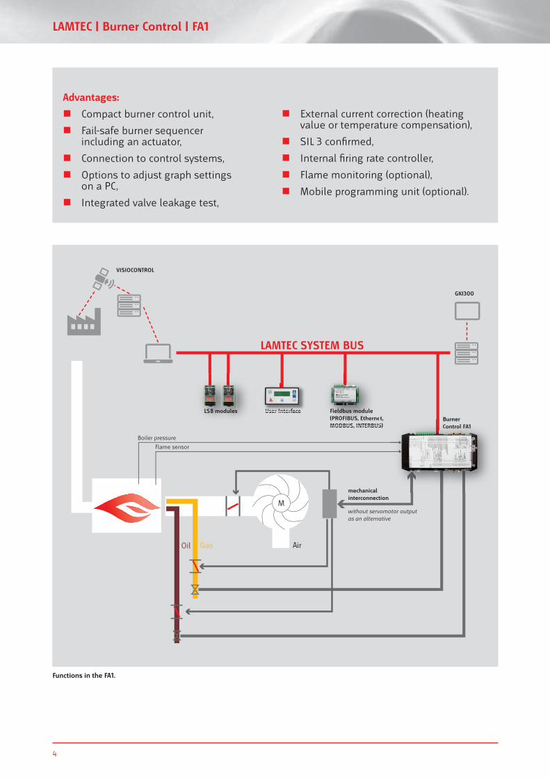
LAMTEC SYSTEM BUS
Boiler pressure
Flame sensor
GasOil
Fieldbus module(PROFIBUS, Ethernet, MODBUS, INTERBUS)
GKI300
Burner Control FA1
User Interface
VISIOCONTROL
Fieldbus module(PROFIBUS, EtherneMODBUS INTERBUS
mechanical interconnection
without servomotor output as an alternative
User InterfaceBurnerControl FA1
LSB modulesLSB sB modules
Air
Functions in the FA1.
Advantages:
Compact burner control unit,
Fail-safe burner sequencerincluding an actuator,
Connection to control systems,
Options to adjust graph settings on a PC,
Integrated valve leakage test,
External current correction (heating value or temperature compensation),
SIL 3 confi rmed,
Internal fi ring rate controller,
Flame monitoring (optional),
Mobile programming unit (optional).
www.lamtec.de 5
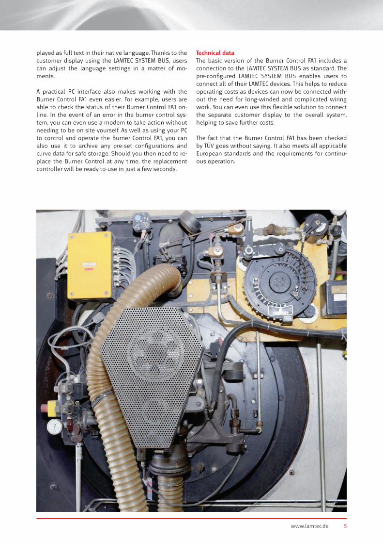
played as full text in their native language. Thanks to the customer display using the LAMTEC SYSTEM BUS, users can adjust the language settings in a matter of mo-ments.
A practical PC interface also makes working with the Burner Control FA1 even easier. For example, users are able to check the status of their Burner Control FA1 on-line. In the event of an error in the burner control sys-tem, you can even use a modem to take action without needing to be on site yourself. As well as using your PC to control and operate the Burner Control FA1, you can also use it to archive any pre-set confi gurations and curve data for safe storage. Should you then need to re-place the Burner Control at any time, the replacement controller will be ready-to-use in just a few seconds.
Technical dataThe basic version of the Burner Control FA1 includes a connection to the LAMTEC SYSTEM BUS as standard. The pre-confi gured LAMTEC SYSTEM BUS enables users to connect all of their LAMTEC devices. This helps to reduce operating costs as devices can now be connected with-out the need for long-winded and complicated wiring work. You can even use this fl exible solution to connect the separate customer display to the overall system, helping to save further costs.
The fact that the Burner Control FA1 has been checked by TÜV goes without saying. It also meets all applicable European standards and the requirements for continu-ous operation.
6
LAMTEC | Burner Control | FA1
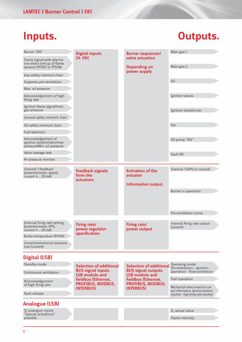
Inputs. Outputs.
Gas safety interlock chain
Suppress pre-ventilation
Max. oil pressure
Acknowledgement of high fi ring rate
Ignition fl ame signal/max. gas pressure
General safety interlock chain
Oil safety interlock chain
Fuel selection
Acknowledgement of ignition position/atomiser pressure/Min. oil pressure
Valve leakage test
Air pressure monitor
Burner "ON" Main gas 1
Main gas 2
Oil
Ignition valves
Ignition transformer
Fan
Oil pump "ON"
Fault FA1
Channel 1 (DPS or current)
Burner in operation
Pre-ventilation active
Channel 1 feedback (potentiometer, speed, current 4 ... 20 mA)
External fi ring rate setting(potentiometer, DPS, current 4 ... 20 mA)
Boiler temperature (Pt100)
Standby mode Operating mode Pre-ventilation – Ignition – Operation – Post-ventilation
12 analogue inputs"Special activations"possible
Continuous ventilation
Fuel operation
O2 actual value
Flame intensity
Acknowledgement of high fi ring rate
Fault release
Mechanical interconnection out-put information: Ignition position reached – high fi ring rate reached
Internal fi ring rate output (current)
Flame signal with alterna-tive direct link-up of fl ame sensors (FFS07 or FFS08)
Digital inputs24 VDC
Burner sequencer/valve actuation
Depending onpower supply
Activation of the actuator
Information output
Feedback signals from the actuators
Firing rate/power regulator specifi cation
Selection of additional BUS signal inputsLSB module and fi eldbus (Ethernet, PROFIBUS, MODBUS, INTERBUS)
Selection of additional BUS signal outputsLSB module and fi eldbus (Ethernet,PROFIBUS, MODBUS, INTERBUS)
Firing rate/power output
Digital (LSB)
Analogue (LSB)
Correction/external tempera-ture (current)
www.lamtec.de 7
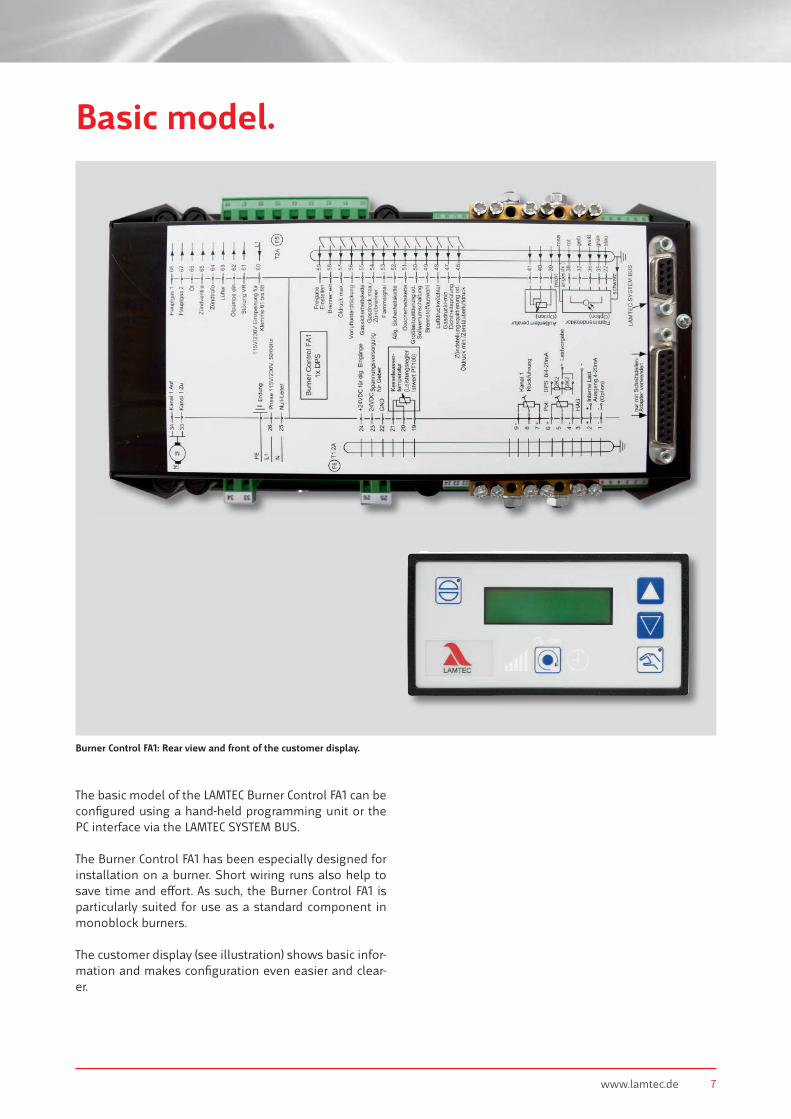
Basic model.
The basic model of the LAMTEC Burner Control FA1 can be confi gured using a hand-held programming unit or the PC interface via the LAMTEC SYSTEM BUS.
The Burner Control FA1 has been especially designed for installation on a burner. Short wiring runs also help to save time and e� ort. As such, the Burner Control FA1 is particularly suited for use as a standard component in monoblock burners.
The customer display (see illustration) shows basic infor-mation and makes confi guration even easier and clear-er.
Burner Control FA1: Rear view and front of the customer display.
8
LAMTEC | Burner Control | FA1
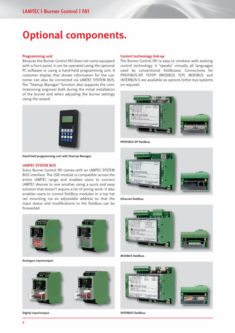
Analogue input/output.
LAMTEC SYSTEM BUSEvery Burner Control FA1 comes with an LAMTEC SYSTEM BUS interface. The LSB module is compatible across the entire LAMTEC range and enables users to connect LAMTEC devices to one another using a quick and easy solution that doesn't require a lot of wiring work. It also enables users to control fi eldbus modules in a top hat rail mounting via an adjustable address so that the input status and modifi cations to the fi eldbus can be forwarded.
Optional components.
Control technology link-upThe Burner Control FA1 is easy to combine with existing control technology. It “speaks” virtually all languages used by conventional fi eldbuses. Connections for PROFIBUS-DP, TCP/IP (MODBUS TCP), MODBUS and INTERBUS-S are available as options (other bus systems on request).
Digital input/output.
MODBUS fi eldbus.
INTERBUS fi eldbus.
Ethernet fi eldbus.
PROFIBUS DP fi eldbus.
Programming unitBecause the Burner Control FA1 does not come equipped with a front panel, it can be operated using the optional PC so� ware or using a hand-held programming unit. A customer display that shows information for the cus-tomer can also be connected via LAMTEC SYSTEM BUS. The "Startup Manager" function also supports the com-missioning engineer both during the initial installation of the burner and when adjusting the burner settings using the wizard.
Hand-held programming unit with Startup Manager.
www.lamtec.de 9
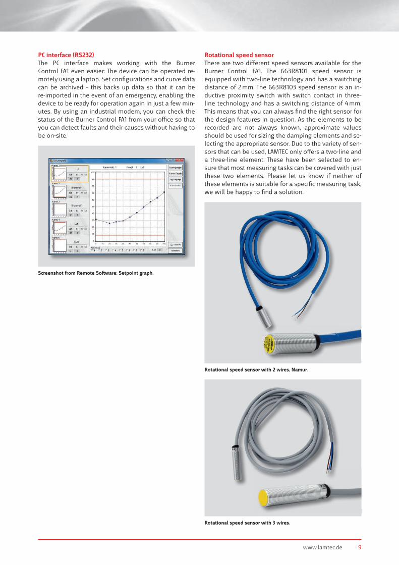
PC interface (RS232)The PC interface makes working with the BurnerControl FA1 even easier: The device can be operated re-motely using a laptop. Set confi gurations and curve data can be archived – this backs up data so that it can be re-imported in the event of an emergency, enabling the device to be ready for operation again in just a few min-utes. By using an industrial modem, you can check the status of the Burner Control FA1 from your o� ce so that you can detect faults and their causes without having to be on-site.
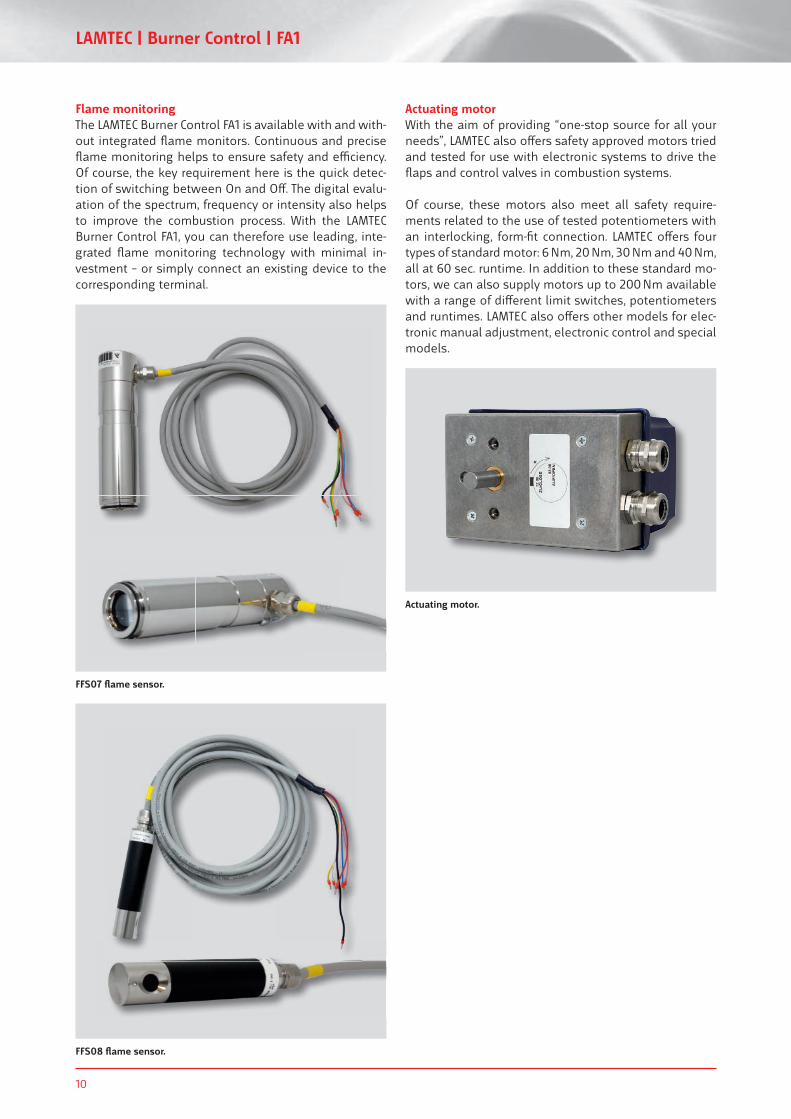
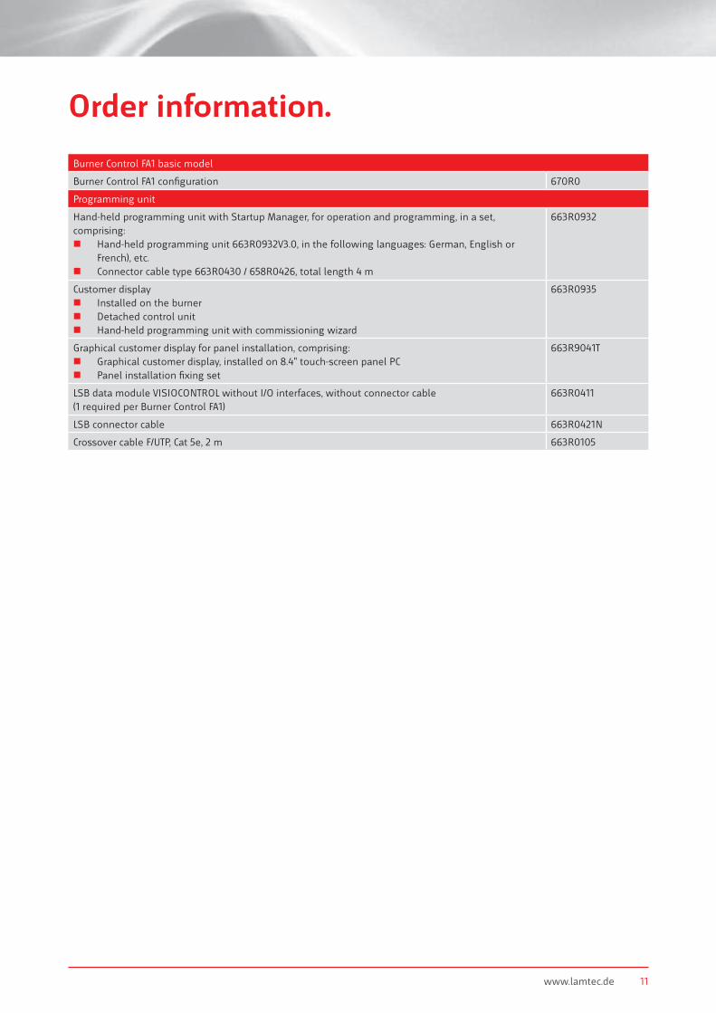
Rotational speed sensorThere are two di� erent speed sensors available for the Burner Control FA1. The 663R8101 speed sensor is equipped with two-line technology and has a switching distance of 2 mm. The 663R8103 speed sensor is an in-ductive proximity switch with switch contact in three-line technology and has a switching distance of 4 mm. This means that you can always fi nd the right sensor for the design features in question. As the elements to be recorded are not always known, approximate values should be used for sizing the damping elements and se-lecting the appropriate sensor. Due to the variety of sen-sors that can be used, LAMTEC only o� ers a two-line and a three-line element. These have been selected to en-sure that most measuring tasks can be covered with just these two elements. Please let us know if neither of these elements is suitable for a specifi c measuring task, we will be happy to fi nd a solution.
Screenshot from Remote So� ware: Setpoint graph.
Rotational speed sensor with 2 wires, Namur.
Rotational speed sensor with 3 wires.
10
LAMTEC | Burner Control | FA1
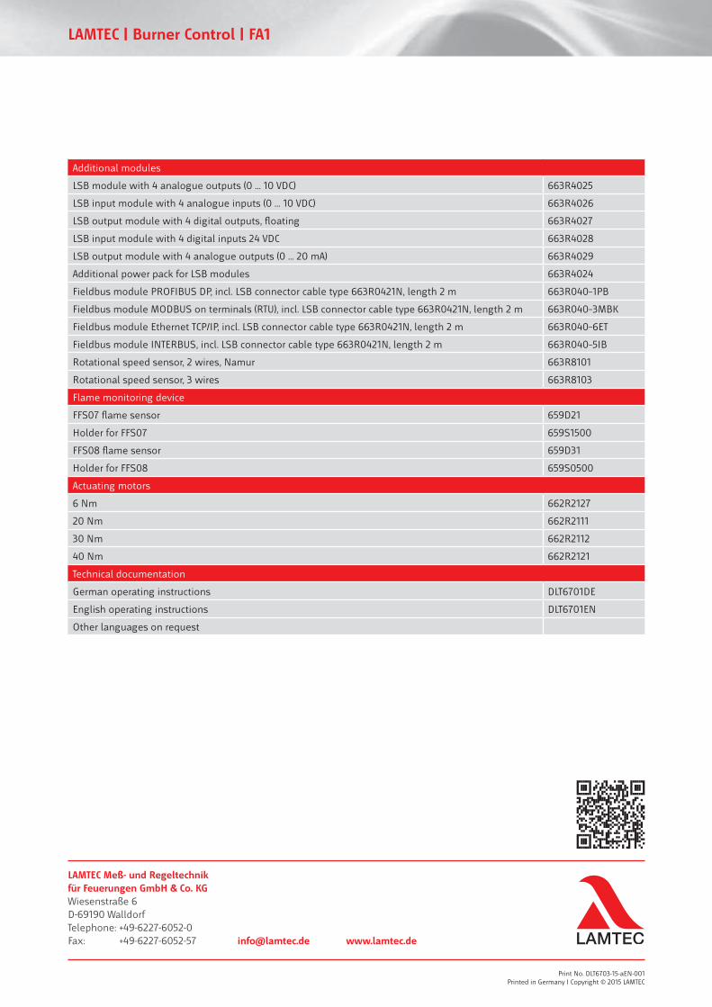
Flame monitoringThe LAMTEC Burner Control FA1 is available with and with-out integrated fl ame monitors. Continuous and precise fl ame monitoring helps to ensure safety and e� ciency. Of course, the key requirement here is the quick detec-tion of switching between On and O� . The digital evalu-ation of the spectrum, frequency or intensity also helps to improve the combustion process. With the LAMTEC Burner Control FA1, you can therefore use leading, inte-grated fl ame monitoring technology with minimal in-vestment – or simply connect an existing device to the corresponding terminal.
FFS07 fl ame sensor.
FFS08 fl ame sensor.
Actuating motorWith the aim of providing “one-stop source for all your needs”, LAMTEC also o� ers safety approved motors tried and tested for use with electronic systems to drive the fl aps and control valves in combustion systems.
Of course, these motors also meet all safety require-ments related to the use of tested potentiometers with an interlocking, form-fi t connection. LAMTEC o� ers four types of standard motor: 6 Nm, 20 Nm, 30 Nm and 40 Nm, all at 60 sec. runtime. In addition to these standard mo-tors, we can also supply motors up to 200 Nm available with a range of di� erent limit switches, potentiometers and runtimes. LAMTEC also o� ers other models for elec-tronic manual adjustment, electronic control and special models.
Actuating motor.
www.lamtec.de 11
Order information.
Burner Control FA1 basic model
Burner Control FA1 confi guration 670R0
Programming unit
Hand-held programming unit with Startup Manager, for operation and programming, in a set, comprising:
Hand-held programming unit 663R0932V3.0, in the following languages: German, English or French), etc.
Connector cable type 663R0430 / 658R0426, total length 4 m
663R0932
Customer display Installed on the burner Detached control unit Hand-held programming unit with commissioning wizard
663R0935
Graphical customer display for panel installation, comprising: Graphical customer display, installed on 8.4" touch-screen panel PC Panel installation fi xing set
663R9041T
LSB data module VISIOCONTROL without I/O interfaces, without connector cable (1 required per Burner Control FA1)
663R0411
LSB connector cable 663R0421N
Crossover cable F/UTP, Cat 5e, 2 m 663R0105
Additional modules
LSB module with 4 analogue outputs (0 ... 10 VDC) 663R4025
LSB input module with 4 analogue inputs (0 ... 10 VDC) 663R4026
LSB output module with 4 digital outputs, fl oating 663R4027
LSB input module with 4 digital inputs 24 VDC 663R4028
LSB output module with 4 analogue outputs (0 ... 20 mA) 663R4029
Additional power pack for LSB modules 663R4024
Fieldbus module PROFIBUS DP, incl. LSB connector cable type 663R0421N, length 2 m 663R040–1PB
Fieldbus module MODBUS on terminals (RTU), incl. LSB connector cable type 663R0421N, length 2 m 663R040–3MBK
Fieldbus module Ethernet TCP/IP, incl. LSB connector cable type 663R0421N, length 2 m 663R040–6ET
Fieldbus module INTERBUS, incl. LSB connector cable type 663R0421N, length 2 m 663R040–5IB
Rotational speed sensor, 2 wires, Namur 663R8101
Rotational speed sensor, 3 wires 663R8103
Flame monitoring device
FFS07 fl ame sensor 659D21
Holder for FFS07 659S1500
FFS08 fl ame sensor 659D31
Holder for FFS08 659S0500
Actuating motors
6 Nm 662R2127
20 Nm 662R2111
30 Nm 662R2112
40 Nm 662R2121
Technical documentation
German operating instructions DLT6701DE
English operating instructions DLT6701EN
Other languages on request
Print No. DLT6703-15-aEN-001Printed in Germany I Copyright © 2015 LAMTEC
LAMTEC | Burner Control | FA1
LAMTEC Meß- und Regeltechnikfür Feuerungen GmbH & Co. KGWiesenstraße 6D-69190 WalldorfTelephone: +49-6227-6052-0Fax: +49-6227-6052-57 [email protected] www.lamtec.de