system i networking ip - ibm · networking ip filtering and network address translation version 5...
TRANSCRIPT

System i
Networking
IP filtering and network address translation
Version 5 Release 4
���


System i
Networking
IP filtering and network address translation
Version 5 Release 4
���

Note
Before using this information and the product it supports, read the information in “Notices,” on
page 33.
Seventh Edition (February 2006)
This edition applies to version 5, release 4, modification 0 of IBM i5/OS (product number 5722–SS1) and to all
subsequent releases and modifications until otherwise indicated in new editions. This version does not run on all
reduced instruction set computer (RISC) models nor does it run on CISC models.
© Copyright International Business Machines Corporation 2000, 2006. All rights reserved.
US Government Users Restricted Rights – Use, duplication or disclosure restricted by GSA ADP Schedule Contract
with IBM Corp.

Contents
IP filtering and network address
translation . . . . . . . . . . . . . . 1
Printable PDF . . . . . . . . . . . . . . 1
Scenarios: Packet rules . . . . . . . . . . . 1
Scenario: Mapping IP addresses using NAT . . . 1
Scenario: Creating filter rules to allow HTTP,
Telnet, and FTP traffic . . . . . . . . . . 4
Scenario: Combining NAT and IP filtering . . . 5
Scenario: Hiding IP addresses using masquerade
NAT . . . . . . . . . . . . . . . . 9
Packet rules concepts . . . . . . . . . . . 11
Packet rules terminology . . . . . . . . . 11
Packet rules versus other i5/OS security
solutions . . . . . . . . . . . . . . 12
Network address translation . . . . . . . . 12
Static (map) NAT . . . . . . . . . . 13
Masquerade (hide) NAT . . . . . . . . 14
Masquerade (port-mapped) NAT . . . . . 15
IP filtering . . . . . . . . . . . . . . 16
Sample filter statements . . . . . . . . 16
IP packet header . . . . . . . . . . . 17
Organizing NAT rules with IP filter rules . . . 18
Organizing multiple IP filter rules . . . . . . 18
Spoof protection . . . . . . . . . . . . 19
Planning for packet rules . . . . . . . . . . 19
Packet rules: User authority requirements . . . 19
Packet rules: System requirements . . . . . . 19
Packet rules: Planning worksheet . . . . . . 20
Configuring packet rules . . . . . . . . . . 20
Accessing the packet rules editor . . . . . . 21
Defining addresses and services . . . . . . 21
Creating NAT rules . . . . . . . . . . . 22
Creating IP filter rules . . . . . . . . . . 23
Defining IP filter interfaces . . . . . . . . 24
Including files in packet rules . . . . . . . 25
Adding comments in the packet rules . . . . 25
Verifying packet rules . . . . . . . . . . 25
Activating packet rules . . . . . . . . . 26
Managing packet rules . . . . . . . . . . 27
Deactivating packet rules . . . . . . . . . 27
Viewing packet rules . . . . . . . . . . 27
Editing packet rules . . . . . . . . . . 28
Backing up packet rules . . . . . . . . . 28
Journaling and auditing packet rules actions by
packet rules . . . . . . . . . . . . . 29
Troubleshooting packet rules . . . . . . . . 29
Related information for packet rules . . . . . . 31
Appendix. Notices . . . . . . . . . . 33
Programming Interface Information . . . . . . 34
Trademarks . . . . . . . . . . . . . . 35
Terms and conditions . . . . . . . . . . . 35
© Copyright IBM Corp. 2000, 2006 iii

iv System i: Networking IP filtering and network address translation

IP filtering and network address translation
IP filtering and network address translation (NAT) act like a firewall to protect your internal network
from intruders.
IP filtering lets you control what IP traffic to be allowed into and out of your network. Basically, it
protects your network by filtering packets according to the rules that you define. NAT, alternatively,
allows you to hide your unregistered private IP addresses behind a set of registered IP addresses. This
helps to protect your internal network from the outside networks. NAT also helps to alleviate the IP
address depletion problem, because many private addresses can be represented by a small set of
registered addresses.
Note: Packet rules is the combination of IP filtering and NAT. When you see the term packet rules used in
this topic collection, the subject applies to both of those components.
In addition to the information in this topic, use the online help available from the Packet Rules Editor in
iSeries™ Navigator. The iSeries Navigator online help offers the tips and techniques for making the most
of the packet rules, including How do I help, Tell me about help, and extensive context-sensitive help.
Printable PDF
Use this to view and print a PDF of this information.
To view or download the PDF version, select IP filtering and network address translation (about 621 KB).
Saving PDF files
To save a PDF on your workstation for viewing or printing:
1. Right-click the PDF in your browser (right-click the link above).
2. Click the option that saves the PDF locally.
3. Navigate to the directory in which you want to save the PDF.
4. Click Save.
Downloading Adobe Reader
You need Adobe Reader installed on your system to view or print these PDFs. You can download a free
copy from the Adobe Web site (www.adobe.com/products/acrobat/readstep.html)
.
Scenarios: Packet rules
You can use network address translation (NAT) and IP filtering to protect your network.
Each scenario includes a diagram and sample configuration.
Tip: In each scenario, the 192.x.x.x IP addresses represent public IP addresses. All addresses are for
example purposes only.
Scenario: Mapping IP addresses using NAT
In this scenario, your company uses static network address translation (NAT) to map its private IP
addresses to public addresses.
© Copyright IBM Corp. 2000, 2006 1
|
|
|

Situation
You own a company and you decide to start a private network. However, you have never registered or
acquired permission to use public IP addresses. When you access the Internet, you find that your
company’s address range is registered to someone else, so you think your current setup is obsolete. You
need to allow public users access to your Web server. What should you do?
Solution
You can use static NAT. Static NAT assigns one original (private) address to one registered (public)
address. Your system maps this registered address to your private address. The registered address enables
your private address to communicate with the Internet. Essentially, it forms a bridge between the two
networks. Communication can be initiated from either network.
By using static NAT, you can keep all of your current internal IP addresses and still access the Internet.
You need to have one registered IP address for each private address that accesses the Internet. For
example, if you have 12 users, you need 12 public IP addresses to map to your 12 private addresses.
In this example, the NAT address, 192.12.3.1, sits unusable, like a shell, waiting for information to come
back. When the information returns, NAT maps the address back to the personal computer. When static
NAT is active, any inbound traffic destined directly to the address 192.12.3.1 never gets to that interface
2 System i: Networking IP filtering and network address translation

because it only represents your internal address. The real private address 10.10.1.1 is the actual
destination, even though (to the world outside the system) it appears that 192.12.3.1 is the required IP
address.
Configuration
To configure the packet rules described in this scenario, you should use the Address Translation wizard
in iSeries Navigator. The wizard requires the following information:
v The private address you want to map: 10.10.1.1
v The public address to which you want to map the private address: 192.12.3.1
v The name of the line over which the address mapping takes place: TRNLINE
To use the Address Translation wizard, follow these steps:
1. In iSeries Navigator, select your system → Network → IP Policies.
2. Right-click Packet Rules, and select Rules Editor.
3. From the Welcome Packet Rules Configuration dialog, select Create a new packet rules file, and click
OK.
4. From the Wizards menu, select Address Translation, and follow the wizard’s instructions to configure
the map-address -translation packet rules.
The packet rules look like the following example.
After you finish creating these rules, you need to verify them to ensure that they can be activated without
errors.
Note: The token ring line that is defined above (LINE=TRNLINE) must be the line that 192.12.3.1 uses.
This static NAT will not work if 10.10.1.1 uses the defined token ring line above. Whenever you
use NAT, you should also enable IP forwarding.
Related concepts
“Static (map) NAT” on page 13Static (map) network address translation (NAT) provides a one-to-one mapping of private IP
addresses to public IP addresses. It allows you to map an IP address on your internal network to an
IP address that you want to make public. Related tasks
“Verifying packet rules” on page 25You always need to verify your rules before you activate them. This ensures that the rules can be
activated without problems.
“Activating packet rules” on page 26Activating the packet rules that you create is the final step in configuring packet rules.
Related reference
“Troubleshooting packet rules” on page 29This topic provides troubleshooting advice for some common packet rules problems.
IP filtering and network address translation 3

Scenario: Creating filter rules to allow HTTP, Telnet, and FTP traffic
In this scenario, your company uses IP filtering to restrict the IP traffic that can access its Web server to
only HTTP, Telnet, and File Transfer Protocol (FTP) traffic.
Situation
You want to provide Web applications to your customers, but your current firewall is working at capacity
and you do not want to add additional traffic to it. Your colleague suggests running the applications
outside the firewall. However, you want only HTTP, FTP, and Telnet traffic to have access to your System
i™ Web server from the Internet. What should you do?
Solution
IP filtering enables you to set rules that define what information can flow through your Web server. In
this scenario, you can write filter rules that permit HTTP, FTP, and Telnet traffic (inbound and outbound).
The public address of the server is 192.54.5.1, and the private IP address is 10.1.2.3.
Configuration
To configure the packet rules described in this scenario, use the Permit A Service wizard in iSeries
Navigator. The wizard requires the following information:
v The type of the service you want to permit: HTTP.
v The public address of the Web server: 192.54.5.1.
v The address of the client: any IP address.
v The interface over which the service runs: TRNLINE.
v The direction the service runs: INBOUND.
v The name you want to use to identify this filter set: external_files.
To use the Permit Service wizard, follow these steps:
1. In iSeries Navigator, select your system → Network → IP Policies.
2. Right-click Packet Rules, and select Rules Editor.
3. From the Welcome Packet Rules Configuration dialog, select Create a new packet rules file, and click
OK.
4 System i: Networking IP filtering and network address translation

4. From the Wizards menu, select Permit A Service, and follow the wizard’s instructions to create the
filter rules.
These packet rules permit HTTP traffic into and out of the system. The packet rules looks like the
following example.
Use the Permit a Service wizard two more times to create filter rules that permit FTP traffic and Telnet
traffic into and out of the system.
After you finish creating these filter rules, verify them to ensure that they can be activated without errors.
Related tasks
“Verifying packet rules” on page 25You always need to verify your rules before you activate them. This ensures that the rules can be
activated without problems.
“Activating packet rules” on page 26Activating the packet rules that you create is the final step in configuring packet rules.
Scenario: Combining NAT and IP filtering
In this scenario, your company combines network address translation (NAT) and IP filtering together.
Your company wants to hide its personal computers and Web server behind a single, public IP address
and wants to allow other companies to access the Web server.
Situation
Your business has a moderately sized internal network that uses a System i model as its gateway. You
want to transfer all Web traffic from the gateway system to a dedicated Web server behind the gateway.
The Web server runs on port 5000. You want to hide all of your private personal computers and the Web
server behind an address on the System i interface, AS02 in the following figure. You also want to allow
other companies to access the Web server. What should you do?
IP filtering and network address translation 5

RZ
AJB
501-1
10.1.1.25110.1.1.252
10.1.1.253
10.1.1.254
Web server10.1.1.250
Internalnetwork
192.27.1.1
Company A10.1.1.*
Company B
System iAS02
System iAS03
FILTERPermits inbound traffic throughto NAT and outbound trafficout to the Internet
NAT10.1.1.251 through10.1.1.254 hidebehind 192.27.1.1
10.1.1.250:5000hide behind192.27.1.1:80
Internet
Solution
You can use IP filtering and NAT together to configure your personal computers and Web server:
v Hide NAT to hide your personal computers behind a public address, 192.27.1.1, so they can access the
Internet.
v Port-mapped NAT to hide your Web server address, 10.1.1.250, and port number, 5000, behind a public
address, 192.27.1.1, and port number, 80. Notice that both NAT rules are hidden behind 192.27.1.1. This
is acceptable as long as the addresses you are hiding do not overlap. The port-mapped NAT rule only
allows externally initiated traffic on port 80 to access your system. If the externally initiated traffic does
not match the exact address and port number, NAT will not translate it and the packet will be
discarded.
v Rules that filter all inbound traffic destined for your private network through to NAT and any
outbound traffic out to the Internet.
Configuration
To configure the hide NAT packet rules described in this scenario, use the Address Translation wizard in
iSeries Navigator. The wizard requires the following information:
v The set of addresses you want to hide: 10.1.1.251 through 10.1.1.254.
v The interface address behind which you want to hide the set of addresses: 192.27.1.1.
6 System i: Networking IP filtering and network address translation

To use the Address Translation wizard, follow these steps:
1. In iSeries Navigator, select your system → Network → IP Policies.
2. Right-click Packet Rules, and select Rules Editor.
3. From the Welcome Packet Rules Configuration dialog, select Create a new packet rules file, and click
OK.
4. From the Wizards menu, select Address Translation, and follow the wizard’s instructions to configure
the hide address translation packet rules.
This packet rule hides your four personal computers behind a public address so that they can access the
Internet. Your hide NAT packet rule looks like the following example.
To configure the port-mapped NAT, follow these steps:
1. Access the Packet Rules Editor from iSeries Navigator.
2. Create a defined address for the Web server address and port 5000.
a. From the Insert menu, select Address.
b. On the General page, enter Web250 in the Address name field.
c. Select IP addresses in the Defined address list. Then click Add and enter the IP address of the
Web server 10.1.1.250 in the field.
d. Click OK.3. Create a defined address to represent the public address 192.27.1.1.
Note: Because you already created a defined address to represent the public address 192.27.1.1 when
you configured the hide NAT packet rules, you can omit this step for this particular scenario
and skip to Step 4. However, if you use these instructions to configure the port-mapped NAT
for your own network and you did not configure the hide NAT packet rules, then continue
with the instructions for this step:
a. From the Insert menu, select Address.
b. On the General page, enter or select BEHIND1 in the Address name field.
c. Select IP addresses in the Defined address list. Then click Add and enter 192.27.1.1 in the IP
addresses edit field.
d. Click OK.4. Create the port-mapped NAT rule:
a. From the Insert menu, select Hide.
b. On the General page, select Web250 from the Hide address name list.
c. Select BEHIND1 from the Behind address name list.
d. Select Allow inbound connections, and enter 5000 in the Hide port field.
e. Enter 80 in the Behind port field.
f. Enter 16 and select seconds in the Timeout fields.
g. Enter 64 in the Maximum conversations field.
IP filtering and network address translation 7

h. Select OFF from the Journaling list.
i. Click OK.
This port-mapped NAT hides your Web server address and port number behind a public address and
port number. Notice that both NAT rules are hidden behind one common IP address. This is acceptable
as long as the addresses you are hiding do not overlap. This port-mapped NAT rule only allows
externally initiated traffic on port 80 to access your system.
The port-mapped NAT rule looks like the following example:
ADDRESS Web250 IP = 10.1.1.250
ADDRESS BEHIND1 IP = 192.27.1.1
HIDE Web250:5000 BEHIND BEHIND1:80 TIMEOUT = 16 MAXCON = 64 JRN = OFF
To create the filter rules described in this scenario, follow these steps:
1. Access the Packet Rules Editor from iSeries Navigator.
2. Create a filter rule to permit inbound traffic destined for your private network.
a. From the Welcome Packet Rules Configuration dialog, select Create a new packet rules file, and
click OK.
b. From the Insert menu, select Filter.
c. On the General page, enter external_rules in the Set name field.
d. Select PERMIT from the Action list.
e. Select INBOUND from the Direction list.
f. Select = and * from the Source address name lists.
g. Select = and enter 192.27.1.1 in the Destination address name fields.
h. Select OFF from the Journaling list.
i. On the Services page, select Service.
j. Select TCP from the Protocol list.
k. Select = and * from the Source port lists.
l. Select = and * from the Destination port lists.
m. Click OK.3. Create a filter rule to permit outbound traffic from your private network to the Internet:
a. From the Welcome Packet Rules Configuration dialog, select Open an existing packet rules file,
and click OK.
b. From the Open File dialog, select the external_rules file, and click Open.
c. From the Insert menu, select Filter.
d. On the General page, select external_rules from the Set name list.
e. Select PERMIT from the Action list.
f. Select OUTBOUND from the Direction list.
g. Select = and enter 192.27.1.1 in the Source address name fields.
h. Select = and * from the Destination address name lists.
i. Select OFF from the Journaling list.
j. On the Services page, select Service.
k. Select TCP from the Protocol list.
l. Select = and * from the Source port lists.
m. Select = and * from the Destination port lists.
n. Click OK.4. Define a filter interface for the filter set that you created:
a. From the Insert menu, select Filter interface.
8 System i: Networking IP filtering and network address translation

b. Select Line name and select TRNLINE from the Line name list.
c. On the Filter Sets page, select external_rules from the Filter set list, and click Add.
d. Click OK.
These filters, in conjunction with the HIDE statement, permit any inbound traffic destined for your
private network through to NAT and any outbound traffic out to the Internet. However, NAT enables
only externally initiated traffic on port 80 to enter the system. NAT does not translate externally initiated
traffic that does not match the port-mapped NAT rule. The filter rules look like the following example:
FILTER SET external_files ACTION = PERMIT DIRECTION = INBOUND SRCADDR = * DSTADDR = 192.27.1.1
PROTOCOL = TCP DSTPORT = * SRCPORT = * JRN = OFF
FILTER SET external_files ACTION = PERMIT DIRECTION = OUTBOUND SRCADDR = 192.27.1.1 DSTADDR = *
PROTOCOL = TCP DSTPORT = * SRCPORT = * JRN = OFF
This statement binds (associates) the ’external_rules’ filter set with the correct physical interface.
FILTER_INTERFACE LINE = TRNLINE SET = external_files
After you finish creating these filter rules, you should verify them to ensure they will be activated
without errors. After that, you can activate them.
Related tasks
“Verifying packet rules” on page 25You always need to verify your rules before you activate them. This ensures that the rules can be
activated without problems.
“Activating packet rules” on page 26Activating the packet rules that you create is the final step in configuring packet rules.
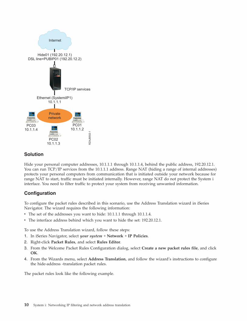
Scenario: Hiding IP addresses using masquerade NAT
In this scenario, your company uses masquerade network address translation (NAT) to hide the private
addresses of your personal computers. At the same time, your company enables your employees to access
the Internet.
Situation
You have a small company and you want to allow HTTP service on your System i platform. Your system
has one Ethernet card and three personal computers. Your Internet service provider (ISP) provides you
with a Digital Subscriber Line (DSL) connection and a DSL modem. The ISP also assigns you the
following public IP addresses: 192.20.12.1 and 192.20.12.2. All of your personal computers have 10.1.1.x
addresses on the internal network. You want to ensure that the private addresses of your personal
computers remain hidden to prevent external users from initiating communications with your internal
network, while allowing your employees to access the Internet. What should you do?
IP filtering and network address translation 9
RZ
AJB
502-1
Internet
TCP/IP services
Hide01 (192.20.12.1)DSL line=PUBIP01 (192.20.12.2)
PC0310.1.1.4
Privatenetwork
PC0210.1.1.3
PC0110.1.1.2
Ethernet (SystemiIP1)10.1.1.1
Solution
Hide your personal computer addresses, 10.1.1.1 through 10.1.1.4, behind the public address, 192.20.12.1.
You can run TCP/IP services from the 10.1.1.1 address. Range NAT (hiding a range of internal addresses)
protects your personal computers from communication that is initiated outside your network because for
range NAT to start, traffic must be initiated internally. However, range NAT do not protect the System i
interface. You need to filter traffic to protect your system from receiving unwanted information.
Configuration
To configure the packet rules described in this scenario, use the Address Translation wizard in iSeries
Navigator. The wizard requires the following information:
v The set of the addresses you want to hide: 10.1.1.1 through 10.1.1.4.
v The interface address behind which you want to hide the set: 192.20.12.1.
To use the Address Translation wizard, follow these steps:
1. In iSeries Navigator, select your system → Network → IP Policies.
2. Right-click Packet Rules, and select Rules Editor.
3. From the Welcome Packet Rules Configuration dialog, select Create a new packet rules file, and click
OK.
4. From the Wizards menu, select Address Translation, and follow the wizard’s instructions to configure
the hide-address -translation packet rules.
The packet rules look like the following example.
10 System i: Networking IP filtering and network address translation

After you finish creating these filter rules, you should verify them to ensure that they will activate
without errors. After that, you can activate them.
Related concepts
“Masquerade (hide) NAT” on page 14Masquerade (hide) network address translation (NAT) enables you the actual address of a personal
computer private. NAT routes traffic from your personal computer to your system, which essentially
makes the system the gateway for your personal computer. Related tasks
“Verifying packet rules” on page 25You always need to verify your rules before you activate them. This ensures that the rules can be
activated without problems.
“Activating packet rules” on page 26Activating the packet rules that you create is the final step in configuring packet rules.
Packet rules concepts
Packet rules comprise both network address translation (NAT) rules and IP filtering rules. These two
rules run at the IP layer of the TCP/IP stack and help protect your system against potential risks that are
commonly associated with TCP/IP traffic.
To better understand how packet rules work, you need to be familiar with the following concepts and
how they apply to your system:
v Packet rules versus other i5/OS® security solutions
v NAT
Packet rules terminology
Here are the useful terms related to the packet rules.
border address
A border address is a public address that acts as a boundary between a trusted and an untrusted
network. It describes the IP address as an actual interface on the system. The system needs to
know the type of address you are defining. For example, your personal computer’s IP address is
trusted, but your system’s public IP address is a border address.
firewall
A logical barrier around systems in a network. A firewall consists of hardware, software, and a
security policy that controls the access and flow of information between secure (trusted) systems
and nonsecure (untrusted) systems.
maxcon
Maxcon is a parameter that is part of masquerade network address translation (NAT) filter rule. It
is the number of conversations that can be active at one time. You are required to define this
number when you set up NAT masquerade rules. The default value is 128. Maxcon only pertains
to masquerade NAT rules.
IP filtering and network address translation 11
||||

NAT conversation
A NAT conversation is a relationship between any of the following IP addresses and port
numbers:
v Private source IP address and source port number (without NAT).
v Public (NAT) source IP address and public (NAT) source port number.
v Destination IP address and port number (an external network).
PPP filter identifier
A PPP filter identifier allows you to apply filter rules to an interface that has been defined in a
point-to-point profile. The PPP filter identifier also links the filter rules to groups of users in a
point-to-point profile. Because the point-to-point profile is associated with a specific IP address,
the filter identifier implicitly defines the interface to which the rules apply.
timeout
Timeout controls the amount of time a conversation is allowed to last. If you have timeout set too
short, the conversation is stopped too quickly. The default value is 16. Related information
Scenario: Managing remote user access to resources using group policies and IP filtering
Packet rules versus other i5/OS security solutions
In high-risk situations, such as securing a production system or securing communications between your
System i platform and other systems in a network, you might need to investigate other security solutions
to broaden your protection.
Your system has integrated security components that can protect your system from several types of risks.
Packet rules provide an economical way for you to secure your system. In some cases, packet rules can
provide everything you need without any additional purchases.
See these information center topics for information to help you ensure that your security strategy
includes multiple lines of defense:
v System i and Internet security
This topic collection provides information about the risks and solutions that you need to consider
before using the Internet.
v Secure Sockets Layer (SSL)
SSL provides secure connections between server applications and their clients. This topic includes
information about how you can enable SSL on your i5/OS applications.
v Virtual Private Networking (VPN)
VPN enables your company to securely extend its private intranet over the existing framework of a
public network, such as the Internet. This topic describes VPN and tells you how to use it on your
system.
Network address translation
Network address translation (NAT) enables you to access the Internet safely without having to change
your private network IP addresses.
IP addresses are depleting rapidly due to widespread Internet growth. Organizations use private
networks, which allows them to select any IP addresses they want. However, if two companies have
duplicate IP addresses and they attempt to communicate with each other, they will have problems. In
order to communicate on the Internet, you must have a unique, registered address. Just as the name
implies, NAT is a mechanism that translates one Internet Protocol (IP) address into another.
12 System i: Networking IP filtering and network address translation
Packet rules contains three methods of NAT. You commonly use NAT to map addresses (static NAT) or
hide addresses (masquerade NAT). By hiding or mapping addresses, NAT solves various addressing
problems.
Example: Hiding internal IP addresses from public knowledge
You are configuring a System i platform as a public Web server. However, you do not want external
networks to know your system’s real internal IP addresses. You can create NAT rules that translate your
private addresses to public addresses that can access the Internet. In this instance, the true address of the
system remains hidden, making the system less vulnerable to attack.
Example: Converting an IP address for an internal host into a different IP address
You want private IP addresses on your internal network to communicate with Internet hosts. To arrange
this, you can convert an IP address for an internal host into a different IP address. You must use public
IP addresses to communicate with Internet hosts. Therefore, you use NAT to convert your private IP
addresses to public addresses. This ensures that IP traffic from your internal host is routed through the
Internet.
Example: Making the IP addresses of two different networks compatible
You want to allow a host system in another network, such as a vendor company, to communicate with a
specific host in your internal network. However, both networks use private addresses (10.x.x.x), which
creates a possible address conflict for routing the traffic between the two hosts. To avoid conflict, you can
use NAT to convert the address of your internal host to a different IP address.
Related reference
“Creating IP filter rules” on page 23When you create a filter, you specify a rule that governs the IP traffic flow into and out of your
system.
Static (map) NAT
Static (map) network address translation (NAT) provides a one-to-one mapping of private IP addresses to
public IP addresses. It allows you to map an IP address on your internal network to an IP address that
you want to make public.
Static NAT allows communication to be initiated from your internal network or an external network, like
the Internet. It is especially useful if you have a system within your internal network that you want to
allow public users to access. In this case, you need to create a NAT rule that maps the actual system
address to a public address. The public address becomes external information. This ensures that private
information remains out of the hands of someone who might attack your systems.
The following list highlights the features of static NAT:
v It is a one-to-one mapping.
v It can be initiated by the external and internal network.
v The address you associate or map to can be any address.
v The address you associate or map to becomes unusable as an IP interface.
v Do not use port-mapped NAT.
Attention: Use static NAT with caution if you decide to map a personal computer to the well-known
address of the System i platform. The well-known address is the IP address reserved for most Internet and
intranet traffic. If you do map to this IP address, NAT will translate and send all traffic to the internal
private address. Because this interface is reserved for NAT, your system and the interface become
unusable.
Related concepts
IP filtering and network address translation 13

“Scenario: Mapping IP addresses using NAT” on page 1In this scenario, your company uses static network address translation (NAT) to map its private IP
addresses to public addresses.
Masquerade (hide) NAT
Masquerade (hide) network address translation (NAT) enables you the actual address of a personal
computer private. NAT routes traffic from your personal computer to your system, which essentially
makes the system the gateway for your personal computer.
Masquerade NAT allows you to translate multiple IP addresses to another single IP address. You can use
masquerade NAT to hide one or more IP addresses on your internal network behind an IP address that
you want to make public. This public address is the address to which the private addresses are translated
and has to be a defined interface on your system. To be a defined interface, you must define the public
address as a BORDER address.
Hiding multiple addresses
To hide multiple addresses, you specify a range of addresses that NAT should translate through the
system. Here is the general process:
1. The translated IP address replaces the source IP address. This occurs in the IP header of the IP packet.
2. The IP source port number (if there is one) in a Transmission Control Protocol (TCP) or User
Datagram Protocol (UDP) header is replaced with a temporary port number.
3. An existing conversation is the relationship between the new IP source address and port number.
4. This existing conversation enables your NAT server to untranslate IP datagrams from the outside
system.
When you use masquerade NAT, an internal system initiates traffic. When this happens, NAT translates
the IP packet as it passes through the NAT server. Masquerade NAT is a great choice because external
hosts cannot initiate traffic into your network. As a result, your network gains additional protection from
an outside attack. Also, you only need to purchase a single public IP address for multiple internal users.
The following list highlights the features of masquerade NAT:
v Private IP address or range of IP addresses are bound behind a public IP address on the NAT
workstation.
v Masquerade NAT can only be initiated by the internal network.
v Port numbers are associated with random port numbers. This means that both the address and the port
number are hidden from the Internet.
v The registered address on the NAT workstation is a usable interface outside of NAT.
Note:
If parameters are not set to fit your environment, the address translation might not function as
expected. For example, the IP addresses in the packets are not translated or the packets might be
discarded. However, it will not cause any hardware or system damage. If you want to adjust the
values of the parameters, consider the following items:
v You must set MAXCON high enough to accommodate the number of conversations you want to
use. For example, if you are using File Transfer Protocol (FTP), your personal computer will
have two conversations active. In this case, you need to set MAXCON high enough to
accommodate multiple conversations for each personal computer. You need to decide how many
concurrent conversations you want to allow in your network. The default value is 128.
v You must have TIMEOUT (a HIDE rule statement) set high enough to allow enough time for
conversations between personal computers and server. For Hide NAT to occur properly, there
must be an internal conversation in progress. The timeout value tells the code how long to wait
for a reply to this internal conversation. The default value is 16.
14 System i: Networking IP filtering and network address translation

v Masquerade NAT supports only the following protocols: TCP, User Datagram Protocol (UDP),
and Internet Control Message Protocol (ICMP).
v Whenever you use NAT, you must enable IP forwarding. Use the Change TCP/IP Attributes
(CHGTCPA) command to verify that you set IP datagram forwarding to YES. Related concepts
“IP packet header” on page 17You can create filter rules to refer to various portions of IP, TCP, UDP, and ICMP headers.
“Scenario: Hiding IP addresses using masquerade NAT” on page 9In this scenario, your company uses masquerade network address translation (NAT) to hide the
private addresses of your personal computers. At the same time, your company enables your
employees to access the Internet.
Masquerade (port-mapped) NAT
Port-mapped network address translation (NAT) is a variation of masquerade NAT.
In port-mapped NAT, you can specify both the IP address and the port number to translate. This enables
both your internal personal computer and the external workstation to initiate IP traffic. You can use
port-mapped NAT if the external workstation (or client) needs to access workstations or systems inside
your network. Only IP traffic that matches both the IP address and the port number is allowed to access.
Internal initiation
When the internal personal computer with Address 1: Port 1 initiates traffic to an outside workstation, the
translating code will check the NAT rule file for Address 1: Port 1. If both the source IP address (Address
1) and the source port number (Port 1) match the NAT rule, NAT starts the conversation and performs
the translation. The specified values from the NAT rule replace the IP source address and source port
number. Address 1: Port 1 is replaced with Address 2: Port 2.
External initiation
An external workstation initiates IP traffic with the destination IP address of Address 2. The destination
port number is Port 2. The NAT server untranslates the datagram with or without an existing
conversation. In other words, NAT automatically creates a conversation if one does not already exist.
Address 2: Port 2 is untranslated to Address 1: Port 1.
The following list highlights the features of masquerade port-mapped NAT:
v Masquerade port-mapped NAT has a one-to-one relationship.
v Masquerade port-mapped NAT can be initiated by both external and internal networks.
v The registered address that the private address hides behind must be defined on the System i platform
that performs the NAT operations.
v IP traffic outside of NAT operations cannot use the registered address. However, if this address
attempts to use a port number that matches the hidden port in the NAT rule, then the traffic will be
translated. The interface will be unusable.
v Typically the port numbers are mapped to well-known port numbers, so extra information is not
necessary. For example, you can run an HTTP server bound to port 5123, then map this to the public
IP and port 80. If you want to hide an internal port number behind another (uncommon) port number,
the client needs to be physically told the value of the destination port number. If not, it is difficult for
communication to occur.
Notes:
v You must set MAXCON high enough to accommodate the number of conversations you want
to use. For example, if you are using File Transfer Protocol (FTP), your personal computer will
have two conversations active. You need to set MAXCON high enough to accommodate
multiple conversations for each personal computer. The default value is 128.
IP filtering and network address translation 15

v Masquerade NAT supports only the following protocols: TCP, User Datagram Protocol (UDP),
and Internet Control Message Protocol (ICMP).
v Whenever you use NAT, you must enable IP forwarding. Use the Change TCP/IP Attributes
(CHGTCPA) command to verify that IP datagram forwarding is set to YES.
IP filtering
The IP filtering component of packet rules enables you to control what IP traffic you want to allow into
and out of your company’s network.
Use IP filtering to help protect your system by filtering packets according to the rules that you specify.
You can apply filter rules to multiple lines or you can apply different rules to each line. Filter rules are
associated with lines; for example, token ring (trnline), not logical interfaces or IP addresses. The system
checks each packet against each rule that you associate with a line. The rules are checked in a sequential
process. After the system matches the packet to a rule, it stops the process and applies the matching rule.
When your system applies a matching rule, it actually performs the action that is specified by that rule.
v PERMIT — allows the packet to process as usual
v DENY — immediately discards the packet
v IPSEC — sends the packet through a virtual private network (VPN) connection, which you specify in
the filter rule
Note: In this case, IP security protocol (IPSec) is an action that you can define in your filter rules. Even
though this topic does not cover IPSec specifically, it is important to note that filtering and virtual
private networking (VPN) are closely related.
After you apply a rule, the system continues its sequential comparison of rules and packets and assigns
actions to all corresponding rules. If the system is unable to find a matching rule for a particular packet,
the system automatically discards that packet. The system’s default deny rule ensures that the system
automatically discards any packet that is not matched to a filter rule. Note that if a filter rule is designed
to permit traffic in only one direction, such as inbound or outbound, the system implements the default
deny rule in both directions; that is, both inbound and outbound packets are discarded.
Related information
Virtual Private Networking (VPN)
Sample filter statements
The purpose of this sample filter statement is to demonstrate the proper syntax for creating filter rules on
your system and to show you how the various statements work together in a file.
Use them as examples only.
A common filter statement might look like this:
FILTER SET TestFilter ACTION = PERMIT DIRECTION = INBOUND SRCADDR = 162.56.39.100 DSTADDR
= * PROTOCOL = * DSTPORT >= 1024 SRCPORT = 80
This filter will permit all traffic entering the interface (INBOUND) that has a source address of
162.56.39.100, a source port of 80, and destination port greater or equal to 1024.
Because IP traffic typically flows both INBOUND and OUTBOUND over a connection, it is common to
have two related statements to permit traffic in both directions. These two statements are called mirrors
of each other and can be seen in the example that follows:
16 System i: Networking IP filtering and network address translation

FILTER SET TestFilter ACTION = PERMIT DIRECTION = INBOUND SRCADDR = 162.56.39.100 DSTADDR
= * PROTOCOL = * DSTPORT >= 1024 SRCPORT = 80 FILTER SET TestFilter ACTION = PERMIT
DIRECTION = OUTBOUND SRCADDR = * DSTADDR = 162.56.39.100 PROTOCOL = * DSTPORT = 80
SRCPORT >= 1024
You might notice that both of these filter statements have the same set name, TestFilter. All filters with
the same set name are considered to be in the same set. You can have any number of filters in a set.
When you activate filters within a given set, they are processed in the order in which they appear in the
file.
A filter statement alone do not have any effect when you activate rules. You must apply the filter set to a
filter interface. An example of applying the set, TestFilter, to an Ethernet line interface is as follows:
FILTER_INTERFACE LINE = ETH237 SET = TestFilter
After you activate these rules, only IP traffic permitted by the TestFilter set will be permitted over
ETH237.
Note: The system adds a default DENY ALL TRAFFIC rule to the end of any activated filters on an
interface. When you apply rules to the interface through which you are configuring the System i
platform, it is very important that you permit your own workstation or that of anyone else who
might be configuring the system to be connected to the System i platform. Failure to do so causes
a loss of communication with the system.You can also apply multiple sets to a filter interface statement such as in the following example:
FILTER_INTERFACE LINE = ETH237 SET = set1, set2, set3
These sets are processed in the same order as you listed them in the filter interface statement (set1, set2,
and set3). The filters within each set are processed in the order in which they appear in the file. This
means that the ordering of filters between different sets is irrelevant. Filter order matters only when
filters are in the same set.
IP packet header
You can create filter rules to refer to various portions of IP, TCP, UDP, and ICMP headers.
The following list includes the fields you refer to in a filter rule that make up the IP packet header:
v Source IP address
v Protocol (for example, TCP, UDP)
v Destination IP address
v Source port
v Destination port
v IP datagram direction (inbound, outbound, or both)
v TCP SYN bit
For example, you can create and activate a rule that filters a packet based on the destination IP address,
source IP address, and direction (inbound). In this case, the system matches all incoming packets
(according to their origin and destination addresses) with corresponding rules. Then the system takes the
action that you specified in the rule. The system discards any packets that are not permitted in your filter
rules. This is called the default deny rule.
Note: The system applies the default deny rule to packets only if the physical interface has at least one
active rule. This rule can be customer defined or generated by iSeries Navigator. Regardless of
IP filtering and network address translation 17

whether the filter rule permits inbound traffic or outbound traffic, the system implements the
default deny rule in both directions. If there is no filter rule active on the physical interface, the
default deny rule will not work.
Related concepts
“Masquerade (hide) NAT” on page 14Masquerade (hide) network address translation (NAT) enables you the actual address of a personal
computer private. NAT routes traffic from your personal computer to your system, which essentially
makes the system the gateway for your personal computer.
Organizing NAT rules with IP filter rules
While network address translation (NAT) and IP filtering work independently of each other, you can use
NAT in conjunction with IP filtering.
If you choose to apply only NAT rules, your system will only perform address translation. Similarly, if
you choose to apply only IP filter rules, your system will only filter IP traffic. However, if you apply both
types of rules, your system will translate and filter addresses. When you use NAT and filtering together,
the rules occur in a specific order. For inbound traffic, NAT rules process first. For outbound traffic, filter
rules process first.
You might want to consider using separate files to create your NAT and filter rules. Although this is not
necessary, it will make your filter rules easier to read and troubleshoot. Either way (separate or together),
you will receive the same errors. If you decide to use separate files for your NAT and filter rules, you can
still activate both sets of rules. However, you should make sure that your rules do not interfere with one
another.
To activate both NAT and filtering rules at the same time, you need to use the include feature. For
example, you create File A for filter rules and File B for NAT rules. You can include the contents of File B
into File A without rewriting all of your rules.
Related tasks
“Including files in packet rules” on page 25By using the Include feature of the Packet Rules Editor, you can activate more than one packet rules
file on your system.
Organizing multiple IP filter rules
When you create a filter rule, it refers to a one-rule statement. A group of filter rules is called a set. The
filters within a set are processed top to bottom, in physical order. Multiple sets are processed in physical
order within a FILTER_INTERFACE statement.
The following example shows where one set contains three filter statements. Whenever you refer to this
set, all three rules will be included. It is typically easiest to include all of your filter rules in one set.
FILTER SET all ACTION = PERMIT DIRECTION = INBOUND SRCADDR = * DSTADDR %
= * PROTOCOL = TCP/STARTING DSTPORT = * SRCPORT = * FRAGMENTS %
= HEADERS JRN = FULL
FILTER SET all ACTION = PERMIT DIRECTION = INBOUND SRCADDR = * DSTADDR %
= * PROTOCOL = TCP DSTPORT = * SRCPORT = * FRAGMENTS = NONE %
JRN = OFF
FILTER SET all ACTION = PERMIT DIRECTION = INBOUND SRCADDR = * DSTADDR %
= * PROTOCOL = ICMP TYPE = * CODE = * FRAGMENTS = NONE JRN %
= OFF
FILTER_INTERFACE LINE = ETHLINE SET = all
###Ethernet line ETHLINE
18 System i: Networking IP filtering and network address translation
Spoof protection
Spoofing occurs when someone attempts to access your system by pretending to be within a system that
you normally trust within your own network. You need to protect any interfaces that are linked to a
public network from this type of attack.
You can protect against spoofing by completing the Spoof Protection wizard which is available from the
Packet Rules Editor in iSeries Navigator. This wizard helps you to assign rules to your vulnerable
interfaces. After the rules are active, a system from the public (untrusted) network will not be able to act
as a trusted workstation from a private (trusted) network.
Planning for packet rules
Before you connect any of your network resources to the Internet, you need to develop a security plan
and understand the potential security risks involved.
In general, you must gather detailed information about how you plan to use the Internet as well as a
document that describes your internal network configuration. Based on the results of gathering this
information, you can accurately evaluate your security needs. System i and Internet security provides you
with the details you need to create a total network security plan.
After you develop a plan, you can begin to configure your packet rules.
Related tasks
“Configuring packet rules” on page 20This checklist contains an overview of the tasks you must complete to ensure that your rules work
properly when activated.
Packet rules: User authority requirements
Before you can administer packet rules on your System i platform, ensure that you have the necessary
access authorities. You must have *IOSYSCFG special authority in your user profile.
If you plan to administer packet rules from the QSECOFR user ID, or from a user ID of type, *SECOFR,
or you have *ALLOBJ authority, you have the correct authority. If you do not have the correct user ID or
*ALLOBJ authority, you must have authority to the following directories, files and QSYS user ID:
1. Add object authority, *RXW, and data authority, OBJMGT, to these three files:
/QIBM/ProdData/OS400/TCPIP/PacketRules/Template4PacketRules.i3p
/QIBM/ProdData/OS400/TCPIP/PacketRules/Template4PacketRules.txt
/QIBM/ProdData/OS400/TCPIP/PacketRules/Template4PacketRules.tcpipml
2. Add Object authority, *RWX, to the following directories:
/QIBM/UserData/OS400/TCPIP/PacketRules
/QIBM/UserData/OS400/TCPIP/OpNavRules
3. Add Object authority, *RWX, to the following files:
/QIBM/UserData/OS400/TCPIP/OpNavRules/VPNPolicyFilters.i3p
/QIBM/UserData/OS400/TCPIP/OpNavRulesPPPFilters.i3p
4. You also need ADD authority to the QSYS profile, because QSYS owns the newly created rules files.
These are the default directories and files that the Packet Rules Editor uses. If you choose to store your
files in directories other than those in the preceding list, you need authority to those directories.
Packet rules: System requirements
You need to ensure that the system meets the minimum system requirements to work with packet rules.
To function properly on your system, packet rules require the following products:
v OS/400® V5R2 (5722-SS1), i5/OS V5R3, or later.
IP filtering and network address translation 19

v iSeries Access for Windows® (5722-XE1) and iSeries Navigator.
– Network component of iSeries Navigator.v TCP/IP Connectivity Utilities for i5/OS (5722-TC1) must be configured, including IP interfaces, routes,
the local host name, and the local domain name. Related information
TCP/IP Tutorial and Technical Overview
V4 TCP/IP for AS/400: More Cool Things Than Ever
Packet rules: Planning worksheet
You can use the planning worksheet of packet rules to gather detailed information about your packet
rules usage plan.
You need this information to pinpoint your security needs. You can also use this information to configure
your packet rules. You should answer each question before you proceed with configuring packet rules on
your system.
You need this information to create a plan for using packet rules Answers
What is the layout of your network and connections? Create a drawing to show this.
What routers and IP addresses will you use?
What rules will you use to control TCP/IP traffic that passes through your systems? For
each rule that you list, specify these aspects of the TCP/IP traffic flow:
v The type of service that you want to permit or deny (for example, HTTP, File Transfer
Protocol (FTP), and so forth).
v The well-known port number for that service.
v The direction of the traffic.
v Whether the traffic is reply or initiating traffic.
v The IP addresses for the traffic (source and destination).
What IP addresses do you want to map to other addresses or hide behind other addresses?
(You need this list only if you are using network address translation.)
Configuring packet rules
This checklist contains an overview of the tasks you must complete to ensure that your rules work
properly when activated.
You can find the specific information in the Packet Rules Editor online help.
After you have created a plan for packet rules on your system, you should be ready to begin actually
creating and applying them.
__ Access the Packet Rules Editor. Follow these instructions to access the Packet Rules Editor in iSeries Navigator.
20 System i: Networking IP filtering and network address translation

__ Use the wizards provided as part of the Packet Rules Editor (V5R2 and later) to create your rules files:
v Permit a Service Wizard
This wizard generates and inserts a set of packet rule statements that permits the necessary traffic for a
given TCP or User Datagram Protocol (UDP) service.
v Spoof Protection Wizard
This wizard generates and inserts a set of packet rule statements that denies any traffic on an interface that
should only be entering this server through a different interface.
v Address Translation Wizard
This wizard generates and inserts a set of either map or hide packet rules statements.
Depending on what type of rules you want to configure, these wizards create all of the required filter and
network address translation (NAT) statements for you. You can access the wizards from the Wizards menu in
the Packet Rules Editor. If you prefer to write the rules yourself, continue to the next item in the checklist.
__ Define addresses and services by creating aliases for the addresses and services for which you plan to create
multiple rules.
Note: You must define addresses if you want to create NAT rules.
__ Create NAT rules. Perform this task only if you plan to use NAT.
__ Create filter rules to define what filters to apply to the network that this system administrates.
__ Specify any additional files that you want to include in your master rules file. Complete this task only if you
have existing rules files that you want to reuse in a new rules file.
__ Define the interfaces by applying your rules.
__ Make comments to describe what each rules file does.
__ Verify your rules files to ensure that your rules will be activated error free and without problems.
__ Activate your rules file. Packet rules must be activated in order for them to work.
__ Manage packet rules. After you have activated your packet rules, you must manage them periodically to
maintain the security of your system.
Related tasks
“Planning for packet rules” on page 19Before you connect any of your network resources to the Internet, you need to develop a security plan
and understand the potential security risks involved.
“Managing packet rules” on page 27You need to use every possible means to effectively and efficiently manage your packet rules. The
security of your system depends on the accurate and current rules.
Accessing the packet rules editor
You can use the Packet Rules Editor to start creating packet rules on your system. You can create a new
file, edit an existing one, or you can work with the sample files provided on the system.
You must access the Packet Rules Editor through iSeries Navigator.
To access the Packet Rules Editor, follow these steps:
1. In iSeries Navigator, expand your system → Network → IP Policies.
2. Right-click Packet Rules and select Rules Editor.
Use the online help for instructions on how to complete each of these tasks.
Related reference
“Troubleshooting packet rules” on page 29This topic provides troubleshooting advice for some common packet rules problems.
Defining addresses and services
When you create packet rules, you must specify the IP addresses and services to which you want the
rules to apply.
IP filtering and network address translation 21

Defined addresses are interface specifications that have been given symbolic names. You should define
addresses when the address you want to represent is a range of addresses, a subnet, a list of
point-to-point identifiers, or a list of non-contiguous addresses. A defined address statement is required
when you plan to create map address translation rules. If the address you want to represent is a single IP
address in a filter statement, then a defined address statement is not required. Service aliases allow you
to define services and then to reuse them in any number of filters. Service aliases also keep track of the
purposes of different service definitions.
Defining addresses and service aliases makes it easier to create your packet rules. When you create the
rules, you refer to the address nickname or service alias rather than the specific address or service details.
Using nicknames and aliases in your filter rules has the following advantages:
v Minimizes the risks of typographical errors.
v Minimizes the number of filter rules that you need to create.
For example, you have users on your network who need Internet access. However, you want to restrict
these users to Web access only. You have two choices about how to create the filter rules that you need in
this situation.
v Define a filter rule for each user’s IP address.
v Create a nickname for the entire address set that represents your users by defining an address.
The first choice increases your chances of making typographical errors, as well as increasing the amount
of maintenance that you must perform for your rules file. Using the second choice, you only need to
create two filter rules. Use a nickname in each rule to refer to the entire set of addresses to which the rule
applies.
You can also create nicknames for services and use them in the same manner as address nicknames. The
service alias defines what TCP, User Datagram Protocol (UDP), and Internet Control Message Protocol
(ICMP) criteria you want to select. You select the source and destination port that you want to use.
Remember: You must define addresses if you plan to use network address translation (NAT). NAT rules
can only point to a defined address.
For instructions on how to define addresses, service aliases, and ICMP services, use the Packet Rules
Editor online help.
If you plan to use network addresses translation, go to create NAT rules. Otherwise, go to “Creating IP
filter rules” on page 23 to filter IP traffic coming into and going out of your network.
Related tasks
“Adding comments in the packet rules” on page 25You can record how you intend your rules to work by adding comments about your rules files.
Creating NAT rules
You must define the nicknames for the IP addresses you intend to use if you want to use network
address translation (NAT).
You cannot create NAT rules with the standard 32-bit address notation. Rather than specifying a real
address such as 193.112.14.90, you must refer to 193.112.14.90 by a name. The system associates the name
you defined with the corresponding addresses and translates them accordingly. Therefore, you must
define your addresses before your system can apply NAT rules to them.
The Packet Rules Editor enables you to create two types of NAT rules. One type enables you to hide
addresses while the other type enables you to map addresses.
22 System i: Networking IP filtering and network address translation

Hiding Addresses
Hide addresses when you want to keep your private addresses hidden from public view. A hidden
address rule enables you to hide multiple internal addresses behind a single public IP address. This type
of NAT is also known as masquerade NAT.
Mapping Addresses
Map addresses when you want to route traffic from a single public IP address into a single internal
address. This type of NAT is also known as static NAT.
For instructions on how to hide or map addresses, use the Packet Rules Editor online help.
Next Topic
If you plan to filter traffic flowing into and out of your network, go to Creating IP filter rules. Otherwise,
proceed to “Adding comments in the packet rules” on page 25.
Creating IP filter rules
When you create a filter, you specify a rule that governs the IP traffic flow into and out of your system.
The rules you define specify whether the system should permit or deny packets that attempt to access
your system. The system directs IP packets based on the type of information in the IP packet headers. It
also directs the IP packet to the action that you have specified the system to apply. The system discards
any packets that do not match a specific rule. This automatic discard rule is called the default deny rule.
Located at the end of the file, the default deny rule is automatically activated any time a packet does not
match the criteria in any of the preceding rules. You must have at least one filter rule activated for the
default deny rule to be active.
Important: When you apply rules to an interface through which you are configuring the System i
platform, it is very important that you permit your own workstation or that of anyone else
who might be configuring the system. Failure to do so will result in a loss of communication
with the system. If this happens, you need to log on to the system using an interface that still
has connectivity, such as the operators console. Use the RMVTCPTBL command to remove all
the filters on the system.
Before you create your filter rules, you need to determine whether you need to use network address
translation (NAT). If you use NAT rules, you must define addresses and services. NAT is the only
function that requires a defined address, but you can use it for other functions as well. If you define
addresses and services, you can reduce the number of rules that you must create as well as minimizing
the possibility of typographical errors.
Here are some other ways you can use to minimize error and maximize efficiency when creating filter
rules:
v Define one filter rule at a time. For example, create all the permits for Telnet at the same time. This
way you can group associate the rules whenever you refer to them.
v Filter rules are processed in the order that they appear in the file. Be sure to order the rules the way
you intend them to be applied when you create them. If the order is incorrect, your system is
vulnerable to attack because the packets will not be processed as you intend them to be. To make
things easier, consider the following optional actions:
– Place your filter set names in the FILTER_INTERFACE statement in the same order in which the sets
are physically defined in the file.
– Place all filter rules in one set to avoid problems with set order.
IP filtering and network address translation 23

v Verify the syntax of each rule as you go along. This is easier and faster than debugging them all at
once.
v Create set names for groups of files that are logically associated with each other. This is important
because only one rule file can be active at a time. See the following example.
v Only write filter rules for the datagrams you want to permit. Everything else will be discarded by the
automatic deny rule.
v Write rules for high traffic volume first.
Example:
Look at the Create set names tip. You might want to enable Telnet access to a number of internal users,
but not to all. To manage these rules easier, you can assign each of them the set name TelnetOK. A second
criteria can enable Telnet through a specific interface and block Telnet traffic from all others. In this case,
you need to create a second set of rules that block Telnet access entirely. You can assign these rules the set
name TelnetNever. By creating set names, you make it easier to distinguish the purpose of the rule. It is
also easier to determine which interfaces you intend to apply to particular sets. Use all of the tips above
to ease the process of creating filters.
For instructions on how to create IP filter rules, use the Packet Rules Editor online help.
After you create your filters, you might want to include files in packet rules in the filter statement. If not,
the next step is to “Defining IP filter interfaces” to which the rules apply.
Related concepts
“Network address translation” on page 12Network address translation (NAT) enables you to access the Internet safely without having to change
your private network IP addresses. Related reference
“Troubleshooting packet rules” on page 29This topic provides troubleshooting advice for some common packet rules problems.
Defining IP filter interfaces
You can define filter interfaces to establish the filter rules that you want the system to apply to each
interface.
Before you can define your filter interfaces, you need to create the filters that you intend the system to
apply to various interfaces. If you choose to define your addresses (when you define your interfaces), you
will refer to them by name. If you choose not to define your addresses (when you define your interfaces),
you will refer to them by IP addresses.
When you create your filters, you can include multiple filters in one set. You then add the set to a
FILTER_INTERFACE statement. The set name used in the statement needs to be a set name that you
defined in a filter statement. For example, if you have a set name, ALL, and all of your filters are in that
set, you must include the set name, ALL, in the filter interface statement for the filters to work properly.
Not only can you have multiple filters in a set, but you can also have multiple sets in a
FILTER_INTERFACE statement.
Before you define your interfaces, you should include any additional files you want to use. Then you can
define your interfaces. Remember that the filter sets are applied in the order that they are specified in the
filter interface statement. So the filter rules should appear in the FILTER_INTERFACE statement in the
same order in which the sets are physically defined in the file.
For instructions on how to define a filter interface, use the Packet Rules Editor online help.
24 System i: Networking IP filtering and network address translation

Including files in packet rules
By using the Include feature of the Packet Rules Editor, you can activate more than one packet rules file
on your system.
Using multiple files makes it much easier for you to work with your rules. Especially, if you need a large
number of rules to control traffic on multiple interfaces. For example, you might want to use a group of
rules on multiple interfaces.
You can create this group within an individual file. Instead of rewriting the rules every time you want to
use them in other files, you can include them in the master file. The master file is the file that can be
active at any given time. You only need to use the include feature to add the rules to your master file.
When creating include files, you might want to keep your NAT rules for an interface separate from your
filter rules for that interface. However, only one file can be active at any given time.
When you create a new rules file, you can include any existing files as part of the new file. Before you do
this, you should create the new filter rules you want to use. Whenever you create a rule, you should file
(group) them by type. This way you do not need to re-create the rules that you have used before. You
can just include or remove them as needed.
For instructions on how to include a file in your rules, use the Packet Rules Editor online help.
Related concepts
“Organizing NAT rules with IP filter rules” on page 18While network address translation (NAT) and IP filtering work independently of each other, you can
use NAT in conjunction with IP filtering.
Adding comments in the packet rules
You can record how you intend your rules to work by adding comments about your rules files.
For example, you might want to record what a particular rule permits or denies. This type of information
can save you hours of time in the future. If you ever need to fix a security problem, you might need
these comments to explain how the rules work. You might not have the time to figure out what your
rules mean at a later time, so use comments generously.
Each of the dialogs associated with creating and activating packet rules has a Description field. This is
the field that is reserved for your comments. The system ignores anything you put in this field. You
might want to use the comment field at each step of the rule creation process. This can reduce your
chance of forgetting to make a significant comment. It is best to make your comments while the process
on which you are commenting is still fresh in your mind. However, you can wait until you finish creating
all your rules.
For instructions on how to make comments in a rules file, use the Packet Rules Editor online help.
Related tasks
“Defining addresses and services” on page 21When you create packet rules, you must specify the IP addresses and services to which you want the
rules to apply.
Verifying packet rules
You always need to verify your rules before you activate them. This ensures that the rules can be
activated without problems.
IP filtering and network address translation 25

When you verify your packet rules, the system checks them for syntax and semantic errors and reports
the results in a message window at the bottom of the Packet Rules Editor. For error messages that are
associated with a specific file and line number, you can right-click the error and select Go To Line to
highlight the error in the file you are editing.
Before using the verify function, you might want to consider viewing your packet rules to check for
visible errors. You cannot activate the rules that have syntactical errors. The verify function checks for
errors of a syntactical nature. The system cannot verify whether you have ordered your rules correctly.
You must check for rule order manually. Packet rules are order-dependent, which means that you must
order the rules the way that you want them applied. If you order them incorrectly, you will not get the
intended result.
For instructions on how to verify packet rules, use the Packet Rules Editor online help.
Related concepts
“Scenario: Mapping IP addresses using NAT” on page 1In this scenario, your company uses static network address translation (NAT) to map its private IP
addresses to public addresses.
“Scenario: Creating filter rules to allow HTTP, Telnet, and FTP traffic” on page 4In this scenario, your company uses IP filtering to restrict the IP traffic that can access its Web server
to only HTTP, Telnet, and File Transfer Protocol (FTP) traffic.
“Scenario: Combining NAT and IP filtering” on page 5In this scenario, your company combines network address translation (NAT) and IP filtering together.
Your company wants to hide its personal computers and Web server behind a single, public IP
address and wants to allow other companies to access the Web server.
“Scenario: Hiding IP addresses using masquerade NAT” on page 9In this scenario, your company uses masquerade network address translation (NAT) to hide the
private addresses of your personal computers. At the same time, your company enables your
employees to access the Internet. Related tasks
“Viewing packet rules” on page 27Before you activate your filter rules, you need to verify that they are correct.
Activating packet rules
Activating the packet rules that you create is the final step in configuring packet rules.
You must activate or load the rules that you created in order for them to work. However, before you
activate your rules, you should verify that they are correct. Always try to resolve any problems before
activating your packet rules. If you activate the rules that have errors or that are ordered incorrectly, your
system will be at risk. Your system has a verify function that is automatically invoked any time you
activate your rules. Because this automatic feature only checks for major syntactical errors, you should
not rely solely on it. Make sure to always manually check for the errors in your rules files as well.
When filter rules are not applied to an interface (for example, you are only using NAT rules, not filtering
rules), a warning (TCP5AFC) appears. This is not an error. It only verifies whether using one interface is
your intention. Always look at the last message. If it says the activation is successful, the messages above
it are all warnings.
Note: When you activate new rules on all interfaces, they replace all the previous rules on all physical
interfaces. Even if a physical interface is not mentioned in the new rules, it will be replaced.
However, if you choose to activate new rules on a specific interface, the rules will only replace the
rules on that specific interface. Existing rules on other interfaces will be untouched.
After your packet rules have been configured and activated, you might need to periodically manage them
to ensure the security of your system.
26 System i: Networking IP filtering and network address translation
Related concepts
“Scenario: Mapping IP addresses using NAT” on page 1In this scenario, your company uses static network address translation (NAT) to map its private IP
addresses to public addresses.
“Scenario: Creating filter rules to allow HTTP, Telnet, and FTP traffic” on page 4In this scenario, your company uses IP filtering to restrict the IP traffic that can access its Web server
to only HTTP, Telnet, and File Transfer Protocol (FTP) traffic.
“Scenario: Combining NAT and IP filtering” on page 5In this scenario, your company combines network address translation (NAT) and IP filtering together.
Your company wants to hide its personal computers and Web server behind a single, public IP
address and wants to allow other companies to access the Web server.
“Scenario: Hiding IP addresses using masquerade NAT” on page 9In this scenario, your company uses masquerade network address translation (NAT) to hide the
private addresses of your personal computers. At the same time, your company enables your
employees to access the Internet. Related tasks
“Managing packet rules”You need to use every possible means to effectively and efficiently manage your packet rules. The
security of your system depends on the accurate and current rules.
Managing packet rules
You need to use every possible means to effectively and efficiently manage your packet rules. The
security of your system depends on the accurate and current rules.
Note: You can find the specific instructions for these tasks in the Packet Rules Editor online help, unless
otherwise noted.
Related tasks
“Configuring packet rules” on page 20This checklist contains an overview of the tasks you must complete to ensure that your rules work
properly when activated.
“Activating packet rules” on page 26Activating the packet rules that you create is the final step in configuring packet rules.
Deactivating packet rules
If you need to make changes to your active packet rules, or you want to activate new rules, you must
first deactivate the currently active rules.
You can choose to deactivate the rules on a specific interface, on a point-to-point identifier, or on all
interfaces and all point-to-point identifiers.
For instructions on how to deactivate your packet rules, use the Packet Rules Editor online help.
Viewing packet rules
Before you activate your filter rules, you need to verify that they are correct.
By viewing the filter rules you create, you can check for any visible errors. You might want to view your
filter rules not only before activating and testing, but also before printing and backing up. Viewing your
rules is not your only way of checking for errors. However, it is a useful way to minimize or remove the
errors before testing.
IP filtering and network address translation 27

You should print out the filter rules you create so that you can look over them. This enables you to catch
any visible mistakes and verify that you included any previously created filter rules files you wanted to
add.
Your system also has a verify function, but do not solely rely on it. You should take the necessary
measures to ensure that you correct all the errors manually. This saves you valuable time and resources.
To view inactive rules, you need to open the rules file in the Packet Rules Editor.
If you want to edit your active filter rules, you should first view them to determine how you want to
change them.
To view your currently active rules, follow these steps:
1. In iSeries Navigator, select your system → Network → IP Policies → Packet Rules.
2. Select the interface for those active packet rules you want to view.
3. View the list of active packet rules in the right pane.
Note: You cannot edit the rules from within this dialog. You must deactivate your rules file and then use
the Packet Rules Editor to edit your rules.
Related tasks
“Verifying packet rules” on page 25You always need to verify your rules before you activate them. This ensures that the rules can be
activated without problems.
“Editing packet rules”As your network security requirements change, you must edit your rules to ensure that they
complement your new security strategy.
Editing packet rules
As your network security requirements change, you must edit your rules to ensure that they complement
your new security strategy.
However, before you can edit your active packet rules, you must first deactivate them. Then, use the
Packet Rules Editor in iSeries Navigator to make the necessary changes to your rules. Make sure that you
verify and then reactivate the rules when you finish editing them.
For instructions on how to edit your packet rules, use the Packet Rules Editor online help.
Related tasks
“Viewing packet rules” on page 27Before you activate your filter rules, you need to verify that they are correct.
Backing up packet rules
By backing up your packet rules files, you can save your time and work to re-create them in the event of
a loss.
These are general tips you can use to ensure that you have an easy way to replace the lost files:
Print out the filter rules
You can store the printouts wherever they are most likely to be secure and reenter the
information as necessary. Printouts are also useful if you need to search for an error in a filter
rule.
For instructions on how to print your packet rules, use the Packet Rules Editor online help.
28 System i: Networking IP filtering and network address translation
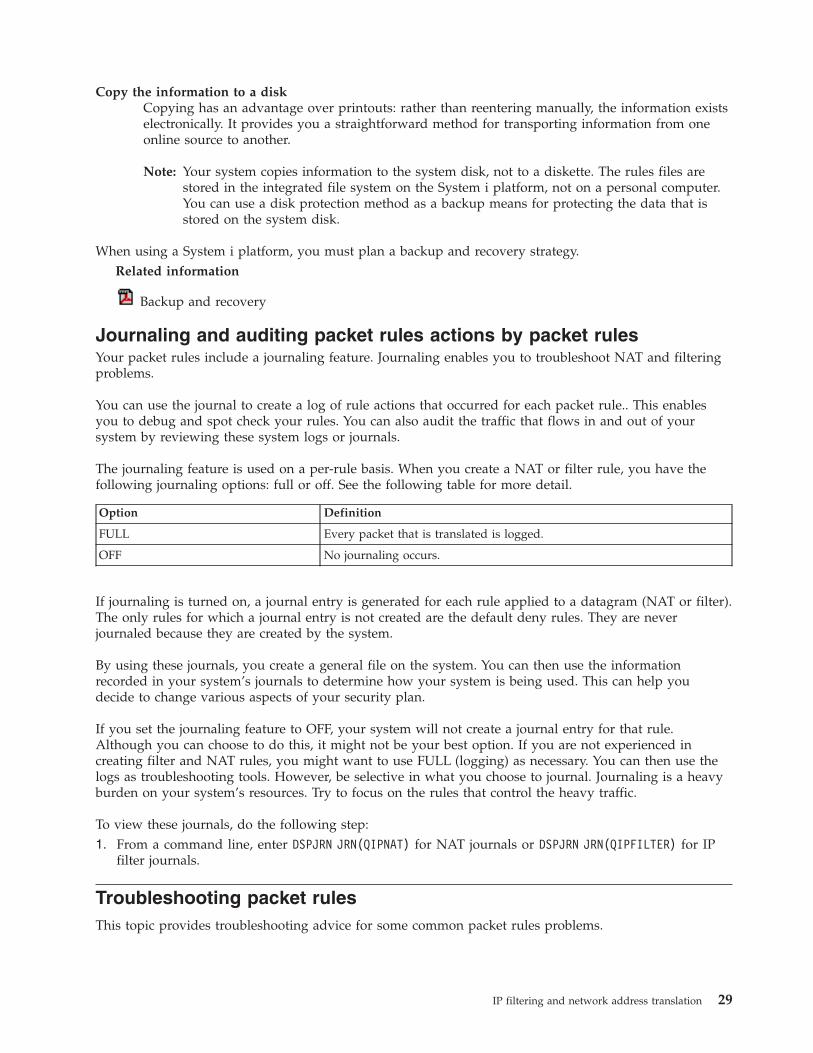
Copy the information to a disk
Copying has an advantage over printouts: rather than reentering manually, the information exists
electronically. It provides you a straightforward method for transporting information from one
online source to another.
Note: Your system copies information to the system disk, not to a diskette. The rules files are
stored in the integrated file system on the System i platform, not on a personal computer.
You can use a disk protection method as a backup means for protecting the data that is
stored on the system disk.
When using a System i platform, you must plan a backup and recovery strategy.
Related information
Backup and recovery
Journaling and auditing packet rules actions by packet rules
Your packet rules include a journaling feature. Journaling enables you to troubleshoot NAT and filtering
problems.
You can use the journal to create a log of rule actions that occurred for each packet rule.. This enables
you to debug and spot check your rules. You can also audit the traffic that flows in and out of your
system by reviewing these system logs or journals.
The journaling feature is used on a per-rule basis. When you create a NAT or filter rule, you have the
following journaling options: full or off. See the following table for more detail.
Option Definition
FULL Every packet that is translated is logged.
OFF No journaling occurs.
If journaling is turned on, a journal entry is generated for each rule applied to a datagram (NAT or filter).
The only rules for which a journal entry is not created are the default deny rules. They are never
journaled because they are created by the system.
By using these journals, you create a general file on the system. You can then use the information
recorded in your system’s journals to determine how your system is being used. This can help you
decide to change various aspects of your security plan.
If you set the journaling feature to OFF, your system will not create a journal entry for that rule.
Although you can choose to do this, it might not be your best option. If you are not experienced in
creating filter and NAT rules, you might want to use FULL (logging) as necessary. You can then use the
logs as troubleshooting tools. However, be selective in what you choose to journal. Journaling is a heavy
burden on your system’s resources. Try to focus on the rules that control the heavy traffic.
To view these journals, do the following step:
1. From a command line, enter DSPJRN JRN(QIPNAT) for NAT journals or DSPJRN JRN(QIPFILTER) for IP
filter journals.
Troubleshooting packet rules
This topic provides troubleshooting advice for some common packet rules problems.
IP filtering and network address translation 29

v i5/OS communications trace capability enables you to see all datagram traffic for a specified interface.
Use the Start Communications Trace (STRCMNTRC) and Print Communications Trace (PRTCMNTRC)
commands to collect and print the information.
v NAT and IP filtering rule order determines how your rules are processed. They are processed in the
order which they appear in the file. If the order is not correct, the packets will not be processed as you
intend. This leaves your system vulnerable to attack. Place your filter set names in the
FILTER_INTERFACE statement in the same order in which the sets are physically defined in the file.
Remember the process shown in the following table.
Inbound traffic process Outbound traffic process
1. NAT rules 1. IP filter rules
2. IP filter rules 2. NAT rules
v Removing all rules is the best way to reset your system and clear out errors. On the System i platform,
issue the Remove TCP/IP Table (RMVTCPTBL) command. If you lock yourself out of the iSeries
Navigator application, you can also use this command to go back and repair any rules.
Note: The Remove TCP/IP Table command also starts the virtual private network (VPN) servers, only
if the VPN servers (IKE and ConMgr) were running before.
v Allowing IP datagram forwarding in your TCP/IP configuration on the system is essential if you are
using NAT. Use the Change TCP/IP Attributes (CHGTCPA) command to verify that the IP datagram
forwarding is set to YES.
v Verifying default return routes ensures that the address that you map to or hide behind is correct.
This address must be routable on the return route back to the system and pass through the correct line
to be untranslated by network address translation (NAT).
Note: If your System i platform has more than one network or line connected to it, you need to be
especially careful about routing inbound traffic. Inbound traffic is handled on any line that it
comes in on, which might not be the correct line waiting to untranslate it.
v Viewing error and warning messages in the EXPANDED.OUT file to ensure that the rules are ordered as
you intend. When you verify and activate a set of filters, these filters are merged with any iSeries
Navigator-generated rules. The combination produces the merged rules in a new file called
EXPANDED.OUT, which is placed in the same directory that contains your rules (typically /QIBM).
Warning and error messages refer to this file. To view this file, complete the following steps to open it
from the Packet Rules Editor:
1. Access the Packet Rules Editor in iSeries Navigator.
2. From the File menu, select Open.
3. Go to the directory, QIBM/UserData/OS400/TCPIP/PacketRules/ or to the directory where you have
saved your packet rules if it is different than the default.
4. From the Open File window, select EXPANDED.OUT file. The EXPANDED.OUT file should appear.
5. Select this file and click Open.
The EXPANDED.OUT file is for your information only. You cannot edit it. Related concepts
“Scenario: Mapping IP addresses using NAT” on page 1In this scenario, your company uses static network address translation (NAT) to map its private IP
addresses to public addresses. Related tasks
“Accessing the packet rules editor” on page 21You can use the Packet Rules Editor to start creating packet rules on your system. You can create a
new file, edit an existing one, or you can work with the sample files provided on the system.
Related reference
30 System i: Networking IP filtering and network address translation

“Creating IP filter rules” on page 23When you create a filter, you specify a rule that governs the IP traffic flow into and out of your
system.
Related information for packet rules
Listed below are the IBM® Redbooks™ (in PDF format) that provide additional information about IP
filtering and network address translation (NAT). You can view or print the PDFs.
IBM Redbooks
v TCP/IP Tutorial and Technical Overview
Find information about security issues related to TCP/IP networks.
v TCP/IP for AS/400®: More Cool Things Than Ever
Find several scenarios that demonstrate NAT and IP packet filtering.
Saving PDF files
To save a PDF on your workstation for viewing or printing:
1. Right-click the PDF in your browser (right-click the link above).
2. Click the option that saves the PDF locally.
3. Navigate to the directory in which you want to save the PDF.
4. Click Save.
Downloading Adobe Reader
You need Adobe Reader installed on your system to view or print these PDFs. You can download a free
copy from the Adobe Web site (www.adobe.com/products/acrobat/readstep.html)
.
Code license and disclaimer information
IBM grants you a nonexclusive copyright license to use all programming code examples from which you
can generate similar function tailored to your own specific needs.
SUBJECT TO ANY STATUTORY WARRANTIES WHICH CANNOT BE EXCLUDED, IBM, ITS
PROGRAM DEVELOPERS AND SUPPLIERS MAKE NO WARRANTIES OR CONDITIONS EITHER
EXPRESS OR IMPLIED, INCLUDING BUT NOT LIMITED TO, THE IMPLIED WARRANTIES OR
CONDITIONS OF MERCHANTABILITY, FITNESS FOR A PARTICULAR PURPOSE, AND
NON-INFRINGEMENT, REGARDING THE PROGRAM OR TECHNICAL SUPPORT, IF ANY.
UNDER NO CIRCUMSTANCES IS IBM, ITS PROGRAM DEVELOPERS OR SUPPLIERS LIABLE FOR
ANY OF THE FOLLOWING, EVEN IF INFORMED OF THEIR POSSIBILITY:
1. LOSS OF, OR DAMAGE TO, DATA;
2. DIRECT, SPECIAL, INCIDENTAL, OR INDIRECT DAMAGES, OR FOR ANY ECONOMIC
CONSEQUENTIAL DAMAGES; OR
3. LOST PROFITS, BUSINESS, REVENUE, GOODWILL, OR ANTICIPATED SAVINGS.
SOME JURISDICTIONS DO NOT ALLOW THE EXCLUSION OR LIMITATION OF DIRECT,
INCIDENTAL, OR CONSEQUENTIAL DAMAGES, SO SOME OR ALL OF THE ABOVE LIMITATIONS
OR EXCLUSIONS MAY NOT APPLY TO YOU.
IP filtering and network address translation 31
|
|
|||||
||
|
||
|
|||

32 System i: Networking IP filtering and network address translation
Appendix. Notices
This information was developed for products and services offered in the U.S.A.
IBM may not offer the products, services, or features discussed in this document in other countries.
Consult your local IBM representative for information on the products and services currently available in
your area. Any reference to an IBM product, program, or service is not intended to state or imply that
only that IBM product, program, or service may be used. Any functionally equivalent product, program,
or service that does not infringe any IBM intellectual property right may be used instead. However, it is
the user’s responsibility to evaluate and verify the operation of any non-IBM product, program, or
service.
IBM may have patents or pending patent applications covering subject matter described in this
document. The furnishing of this document does not grant you any license to these patents. You can send
license inquiries, in writing, to:
IBM Director of Licensing
IBM Corporation
North Castle Drive
Armonk, NY 10504-1785
U.S.A.
For license inquiries regarding double-byte (DBCS) information, contact the IBM Intellectual Property
Department in your country or send inquiries, in writing, to:
IBM World Trade Asia Corporation
Licensing
2-31 Roppongi 3-chome, Minato-ku
Tokyo 106-0032, Japan
The following paragraph does not apply to the United Kingdom or any other country where such
provisions are inconsistent with local law: INTERNATIONAL BUSINESS MACHINES CORPORATION
PROVIDES THIS PUBLICATION “AS IS” WITHOUT WARRANTY OF ANY KIND, EITHER EXPRESS
OR IMPLIED, INCLUDING, BUT NOT LIMITED TO, THE IMPLIED WARRANTIES OF
NON-INFRINGEMENT, MERCHANTABILITY OR FITNESS FOR A PARTICULAR PURPOSE. Some
states do not allow disclaimer of express or implied warranties in certain transactions, therefore, this
statement may not apply to you.
This information could include technical inaccuracies or typographical errors. Changes are periodically
made to the information herein; these changes will be incorporated in new editions of the publication.
IBM may make improvements and/or changes in the product(s) and/or the program(s) described in this
publication at any time without notice.
Any references in this information to non-IBM Web sites are provided for convenience only and do not in
any manner serve as an endorsement of those Web sites. The materials at those Web sites are not part of
the materials for this IBM product and use of those Web sites is at your own risk.
IBM may use or distribute any of the information you supply in any way it believes appropriate without
incurring any obligation to you.
Licensees of this program who wish to have information about it for the purpose of enabling: (i) the
exchange of information between independently created programs and other programs (including this
one) and (ii) the mutual use of the information which has been exchanged, should contact:
IBM Corporation
© Copyright IBM Corp. 2000, 2006 33

Software Interoperability Coordinator, Department YBWA
3605 Highway 52 N
Rochester, MN 55901
U.S.A.
Such information may be available, subject to appropriate terms and conditions, including in some cases,
payment of a fee.
The licensed program described in this information and all licensed material available for it are provided
by IBM under terms of the IBM Customer Agreement, IBM International Program License Agreement,
IBM License Agreement for Machine Code, or any equivalent agreement between us.
Any performance data contained herein was determined in a controlled environment. Therefore, the
results obtained in other operating environments may vary significantly. Some measurements may have
been made on development-level systems and there is no guarantee that these measurements will be the
same on generally available systems. Furthermore, some measurements may have been estimated through
extrapolation. Actual results may vary. Users of this document should verify the applicable data for their
specific environment.
Information concerning non-IBM products was obtained from the suppliers of those products, their
published announcements or other publicly available sources. IBM has not tested those products and
cannot confirm the accuracy of performance, compatibility or any other claims related to non-IBM
products. Questions on the capabilities of non-IBM products should be addressed to the suppliers of
those products.
This information contains examples of data and reports used in daily business operations. To illustrate
them as completely as possible, the examples include the names of individuals, companies, brands, and
products. All of these names are fictitious and any similarity to the names and addresses used by an
actual business enterprise is entirely coincidental.
COPYRIGHT LICENSE:
This information contains sample application programs in source language, which illustrate programming
techniques on various operating platforms. You may copy, modify, and distribute these sample programs
in any form without payment to IBM, for the purposes of developing, using, marketing or distributing
application programs conforming to the application programming interface for the operating platform for
which the sample programs are written. These examples have not been thoroughly tested under all
conditions. IBM, therefore, cannot guarantee or imply reliability, serviceability, or function of these
programs.
Each copy or any portion of these sample programs or any derivative work, must include a copyright
notice as follows:
© (your company name) (year). Portions of this code are derived from IBM Corp. Sample Programs. ©
Copyright IBM Corp. _enter the year or years_. All rights reserved.
If you are viewing this information softcopy, the photographs and color illustrations may not appear.
Programming Interface Information
This IP filtering and network address translation publication documents intended Programming Interfaces
that allow the customer to write programs to obtain the services of IBM i5/OS.
34 System i: Networking IP filtering and network address translation
|||

Trademarks
The following terms are trademarks of International Business Machines Corporation in the United States,
other countries, or both:
AS/400
i5/OS
IBM
IBM (logo)
iSeries
OS/400
Redbooks
System i
Microsoft, Windows, and the Windows logo are trademarks of Microsoft Corporation in the United
States, other countries, or both.
Other company, product, and service names may be trademarks or service marks of others.
Terms and conditions
Permissions for the use of these publications is granted subject to the following terms and conditions.
Personal Use: You may reproduce these publications for your personal, noncommercial use provided that
all proprietary notices are preserved. You may not distribute, display or make derivative works of these
publications, or any portion thereof, without the express consent of IBM.
Commercial Use: You may reproduce, distribute and display these publications solely within your
enterprise provided that all proprietary notices are preserved. You may not make derivative works of
these publications, or reproduce, distribute or display these publications or any portion thereof outside
your enterprise, without the express consent of IBM.
Except as expressly granted in this permission, no other permissions, licenses or rights are granted, either
express or implied, to the publications or any information, data, software or other intellectual property
contained therein.
IBM reserves the right to withdraw the permissions granted herein whenever, in its discretion, the use of
the publications is detrimental to its interest or, as determined by IBM, the above instructions are not
being properly followed.
You may not download, export or re-export this information except in full compliance with all applicable
laws and regulations, including all United States export laws and regulations.
IBM MAKES NO GUARANTEE ABOUT THE CONTENT OF THESE PUBLICATIONS. THE
PUBLICATIONS ARE PROVIDED ″AS-IS″ AND WITHOUT WARRANTY OF ANY KIND, EITHER
EXPRESSED OR IMPLIED, INCLUDING BUT NOT LIMITED TO IMPLIED WARRANTIES OF
MERCHANTABILITY, NON-INFRINGEMENT, AND FITNESS FOR A PARTICULAR PURPOSE.
Appendix. Notices 35
||||||||

36 System i: Networking IP filtering and network address translation


����
Printed in USA