advanced ip networking series: “the network of … · · 2014-01-27" advanced ip...
TRANSCRIPT

Advanced IP Networking Series: “The Network of Networks“
Wayne M. Pecena, CPBE, CBNE
Texas A&M University
Office of Information Technology
Educational Broadcast Services

" Advanced IP Networking Series: The Network of Networks “
• The 15 Minute IP Networking Review
• Why Multiple Networks?
• The Ethernet Switch in Detail
• The Virtual Local Area Network (VLAN)
• VLAN Implementation & Examples
• Summary – Q&A
2
Advertised Webinar Scope: The first of the series offered in 2014 will focus upon implementation of multiple isolated, but structured
networks built upon a common physical infrastructure. Isolated networks examples will include performance, security, and policy factors that may be used in implementation decisions. Implementation
examples will use actual network equipment configuration.
Prerequisite Knowledge: Attendees should have knowledge of IP networking concepts that includes OSI Layers 1-3, Ethernet
switching, IP routing, and VLAN principals.
WEBINAR OUTLINE:

The 15 Minute IP Networking Review
3

What is a Network? • The Foundation for Human Interaction.
• A Group of Computers That are Interconnected to Share Resources and Information.
• A group of Hosts That Share a Common Address Scheme.
• Networks are often defined by their geographic reach:
– Local Area Network - LAN
– Wide Area Network - WAN
– Metropolitan Area Network - MAN
– Campus Area Network – CAN
• Networks Can Be Defined By Their Function:
– Storage Area Network - SAN
4

5 Things Required To Build a Network • Send Host
• Receive Host
• Message or Data to Send Between Hosts
• Media to Interconnect Hosts
• Protocol to Define How Data is Transferred
5

http://babgond.com/images/Tableprotocols.pdf

The OSI Model Open Systems Interconnection (OSI) Model
Developed by the International Organization for Standardization (ISO) A Conceptual Model – Abstract in Nature – Modular in Structure
The OSI Model Does Not Define Standards – Standards Are Built From the OSI Model The OSI Model Defines How Data Traverses From An Application to the Network
The OSI Model Describes How Devices & Protocols Interact
7
Networking Focus

Encapsulation Data is “Encapsulated” As It Travels Through the “Stack” From Application
8

Encapsulation & De-Encapsulation
9

The Network Today! The “de facto” Standard
• Layer 1 is Ethernet based Copper, Fiber, or WiFi in the LAN
• Layer 2 is Ethernet
• Layer 3 is IP
10
“I don’t know what the future network will be, but it will be Ethernet!” Bob Metcalf Father of Ethernet

Layer 2 Standards: IEEE- Institute of Electrical & Electronic Engineers
• Project 802 Ethernet Standards: – 802.1 Bridging
– 802.3 Ethernet
– 802.11 Wireless
11
http://standards.ieee.org/about/get/

Layer 3 Standards: IETF – Internet Engineering Task Force
• Request for Comments – RFC’s
– The “Standards Bible” of the Internet
– Used to Explain All Aspects of IP Networking
– Nomenclature “RFC xxxx”
• Requirement Levels:
– Required
– Recommended
– Elective
– Limited Use
– Not Recommended
12
www.rfc-editor.org/rfc.html

The Layer 2 Ethernet Frame
Preamble TypeSourceAddress
DestinationAddress Data CRC
An Ethernet II (DIX) Frame
8BYTES
6BYTES
6BYTES
2BYTES
46 – 1500 BYTESVARIABLE
4BYTES
TypeSourceAddress
DestinationAddress Data CRC
64 Byte Minimum
IFGap
12BYTES
framelength
13
< 64 bytes results in a “runt” frame

Ethernet Frame Flow Through Network
14
MAC Address Changes As Frame Passes Through the Network

Addressing Review
• MAC Address – 6 Bytes – Hexadecimal Notation - 00:12:3F:8D:4D:A7
– Layer 2 Physical Address (local network segment)
– Fixed – Assigned by NIC Mfg.
– Local Scope
• IP Address – 4 Bytes – Doted Decimal Notation - 172.15.1.1
– Layer 3 Logical Address (global routed)
– Can Change – Determined by Network - Assigned by User
– Global Scope
15
172.15.1.1 172.15.2.2 DATA Trailer00:12:3F:8D:4D:A7FF:FF:FF:FF:FF:FF
DestinationMAC
SourceMAC
DestinationIP
SourceIP
IP Packet
Ethernet Frame
Simplified Representation

MAC Address Formats Always 48 Bits – Always Expressed as Hexadecimal
16
Byte6
Byte1
Byte2
Byte3
Byte4
Byte5
6 Bytes
Organization UniqueIdentifier “OUI”
Network InterfaceController “NIC”
Can Be Represented in Several Formats:
00:A0:C9:14:C8:29
00-A0-C9-14-C8-29
00A0.C914.C829

Hubs, Switches. & Routers A Summary!
• Hub – Layer 1 Device
– Acts as a Repeater - All Incoming Frame FWD Out Every Other Port
– Half-Duplex Based – CSMA/CD Algorithm Controled
– No Intelligence – Collision & Broadcast Domain Across All Ports
• Switch – Layer 2 Device – Originally Called “Forwarding”- Now Called “Switching”
– Full Duplex Based
– Intelligence Based – Selectively Forwards Frame to a Port
– Each Port is a Collision Domain (assuming one device per port)
– Each Switch is a Broadcast Domain
• Router – Layer 3 Device
– Forwards Packets Between Different Networks
– Separates Broadcast Domains
– Each Interface is a Collision Domain
17
X

Why Multiple Networks?
18

The Network
• One Network – Single Broadcast Domain – “Flat” Topology
• Multiple Networks – Individual Broadcast Domains – “Segmented”
• Policy
• Regulation
• Security
• Performance
19
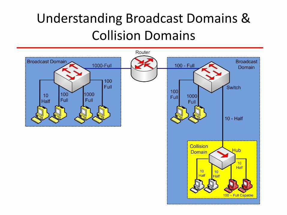
Understanding Broadcast Domains & Collision Domains
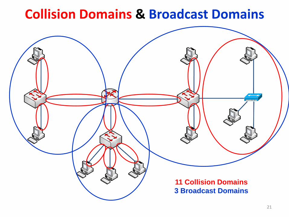
Collision Domains & Broadcast Domains
21
11 Collision Domains 3 Broadcast Domains

The Ethernet Switch in Detail
22

Managed vs Un-Managed Ethernet Switches
• Managed Switch – User Configurable
– Provides Ability to Control & Monitor Host Communications
– Port Configuration , Security, & Monitoring
– VLAN Implementation
– Redundancy Supported (STP)
– QoS (Prioritization) Implementation
– Port Mirroring
• Un-Managed Switch – Fixed Configuration
– “Plug & Play”
– Provides Basic Host Communications
– Cheaper
23

Ethernet Switch Functions • Learn MAC Addresses
• Filter Ethernet Frames
• Forward Ethernet Frames
• Flood Ethernet Frames
• Allow Redundancy (Avoid loops where redundant links exist)
• Can Provide Port Security Features

Ethernet Switching Fundamentals “Bridging”
• Switches Allow Segmentation of Network – Allows Dedicated Bandwidth and Creates Point-Point Communication
– Increased Throughput Due to Zero or Minimal Collisions
– Provides Full-Duplex Operation
– Increased Security Capability
• Switches Selectively Forward Individual “Frames” from a Receiving Port to a Destination Port – Builds Internal Table of Destination Address on each Port
– Forwards Ethernet Frame if in Table
– Floods Ports if Frame Not in Table OR a Broadcast Frame

Simplified Ethernet Switch Internals
26

Learning a MAC Address
A Real MAC Address Table
NOTE VLAN 1 is Special

The Virtual Local Area Network “VLAN”
28

Virtual Local Area Network – VLAN
• Allows Separation or Segmentation of Networks Across a Common Physical Media
– Creates Subset of Larger Network
– VLAN Control of Broadcast Domains – Each VLAN is a Broadcast Domain
– Architecture Flexibility
– Security
• Static Port Based VLAN(s) – Most Popular
– Manual Configuration
– Switch Port Security Features
• Dynamic Port Based – MAC-Based VLAN(s)
• Assignment Based Upon MAC Address
– Protocol-Based VLAN(s) • Assignment Based Upon Protocol
29

VLAN Example
30
Switch Port Type Configuration:
Access Link – Member of One VLAN Only Connects to a Host Trunk Link – Carries Traffic From Multiple VLANS Between Switches

Switch Interface Configuration
31

Broadcast Domains
32
No Connectivity Exists Between Broadcast Domain, Networks, or Subnets!

Adding the VLAN Tag
33
PREAMBLE SOURCE MAC ADDRESS
DESTINATION MAC ADDRESS TYPE DATA CRC
PREAMBLE SOURCE MAC ADDRESS
DESTINATION MAC ADDRESS TYPE DATA CRCTAG
TPID “0X8100” PRICFI
VLANID
ETHERNET FRAME
802.1Q ETHERNET FRAME
802.1Q TAG
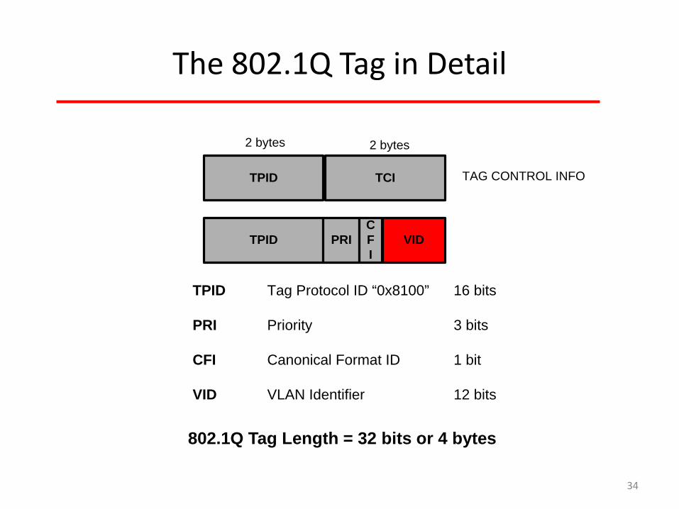
The 802.1Q Tag in Detail
34
TPID PRICFI
VID
TPID Tag Protocol ID “0x8100” 16 bits
PRI Priority 3 bits
CFI Canonical Format ID 1 bit
VID VLAN Identifier 12 bits
TPID TCI TAG CONTROL INFO
2 bytes 2 bytes
802.1Q Tag Length = 32 bits or 4 bytes

Where Does Tagging Occur?
35
Tag added to frame at Egress trunk interface / Tag stripped at Ingress trunk interface

VLAN Implementation & Examples
36

VLAN Configurations


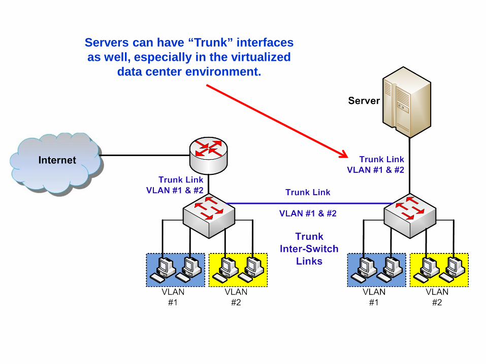
Servers can have “Trunk” interfaces as well, especially in the virtualized
data center environment.
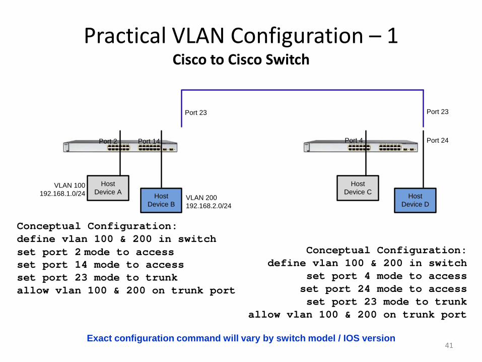
Practical VLAN Configuration – 1 Cisco to Cisco Switch
41
HostDevice A Host
Device B
HostDevice C Host
Device D
VLAN 100192.168.1.0/24 VLAN 200
192.168.2.0/24
Port 2 Port 14
Port 23 Port 23
Port 24Port 4
Conceptual Configuration: define vlan 100 & 200 in switch set port 2 mode to access set port 14 mode to access set port 23 mode to trunk allow vlan 100 & 200 on trunk port
Conceptual Configuration: define vlan 100 & 200 in switch
set port 4 mode to access set port 24 mode to access set port 23 mode to trunk
allow vlan 100 & 200 on trunk port
Exact configuration command will vary by switch model / IOS version

42
HostDevice A Host
Device B
HostDevice C Host
Device D
VLAN 100192.168.1.0/24
VLAN 200192.168.2.0/24
Port 2 Port 14
Port 23
Port 7
Port 18
Port 24
Conceptual Configuration: define vlan 100 & 200 in switch set port 2 mode to access set port 14 mode to access set port 23 mode to trunk allow vlan 100 & 200 on trunk port
Conceptual Configuration: define vlan 100 & 200 in switch set port 7 as untagged vlan 100 set port 24 as untagged vlan 200 set port 18 as tagged vlan 100 & 200
Practical VLAN Configuration – 2 Cisco to HP Switch
Cisco Terminology HP Terminology Access Mode Untagged Trunk Mode Tagged

Summary Q & A
43

Takeaway Points • VLANs Allow a Common Physical Infrastructure to Support Multiple Isolated
Networks
• Each Network, Subnet, or VLAN is a Broadcast Domain With a Unique IP Address Scheme
• Ethernet Switches Minimize Collision Domains
• IP Routing Must Be Used for Communications Between VLANs
• IP Routers Create Broadcast Domains
• Network Traffic May Be Isolated Because of:
– Policy
– Regulations
– Security
– Performance
• An Ethernet Frame is “Tagged” to Denote VLAN Membership on a Trunk Interface
44

Further Study:
45
SBE Networking Certifications CBNT Certified Broadcast Networking Technician
• This certification is designed for persons who wish to demonstrate a basic familiarity with networking hardware as utilized in business and audio/video applications in broadcast facilities.
• Exam Focus: – Network topologies and layouts – Common network protocols – Wiring standards and
practices – Maintenance, troubleshooting and
connectivity issues – Challenges unique to broadcast-
based networks
CBNE Certified Broadcast Networking Engineer
46
• This certification is an “Advanced” level that reflects the skill and knowledge that will be required in today's world of converged IT and broadcast engineering.
• Exam Focus: – Audio/Video over IP
– Digital Content Management
– Video Systems in an IT World
– Data Transmission Systems
– General IT Hardware

47

Thank You for Attending! Wayne M. Pecena Texas A&M University [email protected] [email protected] 979.845.5662
48
? Questions ?