system 800xa 6.0 hi release notes new functions …...a complete and comprehensive list of terms is...
TRANSCRIPT

Power and productivity
for a better world™
System 800xARelease NotesNew Functions and Known Problems
System Version 6.0


System 800xARelease Notes
New Functions and Known Problems
System Version 6.0
NOTICEThis document contains information about one or more ABB products and may include a description ofor a reference to one or more standards that may be generally relevant to the ABB products. The pres-ence of any such description of a standard or reference to a standard is not a representation that all ofthe ABB products referenced in this document support all of the features of the described or referencedstandard. In order to determine the specific features supported by a particular ABB product, the readershould consult the product specifications for the particular ABB product.
ABB may have one or more patents or pending patent applications protecting the intellectual propertyin the ABB products described in this document.
The information in this document is subject to change without notice and should not be construed as acommitment by ABB. ABB assumes no responsibility for any errors that may appear in this document.
Products described or referenced in this document are designed to be connected, and to communicateinformation and data via a secure network. It is the sole responsibility of the system/product owner toprovide and continuously ensure a secure connection between the product and the system networkand/or any other networks that may be connected.
The system/product owners must establish and maintain appropriate measures, including, but not lim-ited to, the installation of firewalls, application of authentication measures, encryption of data, installa-tion of antivirus programs, and so on, to protect the system, its products and networks, against securitybreaches, unauthorized access, interference, intrusion, leakage, and/or theft of data or information.
ABB verifies the function of released products and updates. However system/product owners are ulti-mately responsible to ensure that any system update (including but not limited to code changes, con-figuration file changes, third-party software updates or patches, hardware change out, and so on) iscompatible with the security measures implemented. The system/product owners must verify that thesystem and associated products function as expected in the environment they are deployed.
In no event shall ABB be liable for direct, indirect, special, incidental or consequential damages of anynature or kind arising from the use of this document, nor shall ABB be liable for incidental or consequen-tial damages arising from use of any software or hardware described in this document.
This document and parts thereof must not be reproduced or copied without written permission fromABB, and the contents thereof must not be imparted to a third party nor used for any unauthorized pur-pose.
The software or hardware described in this document is furnished under a license and may be used,copied, or disclosed only in accordance with the terms of such license. This product meets the require-ments specified in EMC Directive 2004/108/EEC and in Low Voltage Directive 2006/95/EEC.
TRADEMARKSAll rights to copyrights, registered trademarks, and trademarks reside with their respective owners.
Copyright © 2003-2015 by ABB. All rights reserved.
Release: September 2015Document number: 2PAA111899-600 F

2PAA111899-600 F 5
Table of Contents
About This Release NoteGeneral ............................................................................................................................13
Release Note Conventions ...............................................................................................13
Warning, Caution, Information, and Tip Icons................................................................13
Terminology.....................................................................................................................14
Released User Manuals and Release Notes.....................................................................14
Section 1 - Release NotesIntroduction .....................................................................................................................17
Products Participating in This Version ............................................................................18
Release Notes Safety Notices .......................................................................................18
Related Documentation ...................................................................................................19
Product Support ...............................................................................................................19
Section 2 - Functionality ChangesIntroduction .....................................................................................................................21
Support for new Operating Systems.....................................................................21
Improved Security ................................................................................................21
Installation............................................................................................................22
Rename PC nodes ................................................................................................22
Engineering Studio installation supported without Microsoft Office as a Pre-requisite ........................................................................................22
ABB Start Menu...................................................................................................23
Base System.....................................................................................................................24
Trends .............................................................................................................24
Alarm List Readability .........................................................................................24

Table of Contents
6 2PAA111899-600 F
Advanced Graphical Elements............................................................................. 24
New Video Server Version................................................................................... 24
Multisystem Integration .................................................................................................. 25
System Services .............................................................................................................. 26
Diagnostics Collection Tool................................................................................. 26
Central License System ....................................................................................... 26
Engineering Studio.......................................................................................................... 26
Process Engineering Tool Integration ............................................................................. 27
800xA for AC 800M ....................................................................................................... 28
Engineering Environment .................................................................................... 28
AC 800M High Integrity...................................................................................... 32
Control and I/O .................................................................................................... 33
Application Change Management................................................................................... 37
PLC Connect ................................................................................................................... 37
Device Management PROFIBUS and HART ................................................................. 38
Device Library Wizard: (DLW) ...................................................................................... 38
Device Management FOUNDATION Fieldbus .............................................................. 39
Fieldbus Builder FOUNDATION Fieldbus (FBBFF).......................................... 39
Linking Device..................................................................................................... 39
800xA for Advant Master and 800xA for Safeguard ...................................................... 40
Advant Master Alarm Refresh ............................................................................. 40
Enhanced RTA unit PU410 firmware .................................................................. 40
RTA board PU515A is no longer supported ........................................................ 40
Controller node objects defined as Entities ......................................................... 40
Advant Master Central Backup............................................................................ 40
800xA for AC 870P / Melody ......................................................................................... 41
Batch Management.......................................................................................................... 41
800xA History ................................................................................................................. 41
800xA for Harmony ........................................................................................................ 42
Section 3 - Installation LaunchPadKnown Problems ............................................................................................................. 43
Installation ........................................................................................................... 43
Table of Contents
2PAA111899-600 F 7
2PAA111899-600 F 7
Section 4 - System InstallationKnown Problems .............................................................................................................45
Operation .............................................................................................................45
Configuration .......................................................................................................48
Section 5 - Base SystemKnown Problems .............................................................................................................49
Installation............................................................................................................49
Administration......................................................................................................50
Configuration .......................................................................................................52
Operation .............................................................................................................54
Instruction Manual Changes ................................................................................56
Section 6 - System ServicesKnown Problems .............................................................................................................57
Central Licensing Service................................................................................................57
Diagnostics Collection Tool ............................................................................................58
Configuration .......................................................................................................58
Operation .............................................................................................................58
Structured Data Logger ...................................................................................................59
Configuration .......................................................................................................59
Section 7 - Engineering StudioKnown Problems .............................................................................................................61
Operation .............................................................................................................61
Section 8 - AC 800MIntroduction .....................................................................................................................81
Safety ..............................................................................................................................81
Version Designation.........................................................................................................82
Software .............................................................................................................82
Hardware .............................................................................................................83
Compatibility ..................................................................................................................83

Table of Contents
8 2PAA111899-600 F
Supported Versions .............................................................................................. 83
Compatible Hardware Modules ...................................................................................... 85
Compatible Firmware...................................................................................................... 89
Included Library Version................................................................................................. 90
Installation of AC 800M HI Extension ........................................................................... 94
AC 800M High Integrity...................................................................................... 94
Step 1: Installation from ZIP-Archive ................................................................. 94
Step 2: Verification of Installation ....................................................................... 96
Step 3: Post Installation - AC 800M HI Controller firmware.............................. 96
Known Problems ............................................................................................................. 97
Installation ........................................................................................................... 97
Administration ..................................................................................................... 97
Configuration ..................................................................................................... 104
Operation .......................................................................................................... 120
Preparations Before an Online Upgrade of an AC 800M using CI857......................... 139
Section 9 - Application Change ManagementKnown Problems ........................................................................................................... 141
Operation .......................................................................................................... 141
Section 10 - PLC Connect and SoftPoint ServerKnown Problems ........................................................................................................... 143
Installation ......................................................................................................... 143
Configuration ..................................................................................................... 143
Operation .......................................................................................................... 145
Section 11 - SFC ViewerKnown Problems ........................................................................................................... 147
Operation .......................................................................................................... 147
Section 12 - Process Engineering Tool IntegrationKnown Problems ........................................................................................................... 151
Installation ......................................................................................................... 151

Table of Contents
2PAA111899-600 F 9
2PAA111899-600 F 9
Operation ...........................................................................................................152
...........................................................................................................154
Section 13 - IEC 61850Known Problems ...........................................................................................................155
Configuration .....................................................................................................155
Operation ...........................................................................................................159
Miscellaneous.....................................................................................................160
Section 14 - Device Management FOUNDATION FieldbusKnown Problems ...........................................................................................................161
Installation..........................................................................................................161
Configuration .....................................................................................................164
Operation ...........................................................................................................175
Section 15 - Device Management PROFIBUS and HARTKnown Problems ...........................................................................................................177
Administration....................................................................................................177
Configuration .....................................................................................................178
Operation ...........................................................................................................185
Miscellaneous.....................................................................................................191
Section 16 - Device Library WizardKnown Problems ...........................................................................................................193
Operation ...........................................................................................................193
Section 17 - Asset OptimizationKnown Problems ...........................................................................................................195
Installation..........................................................................................................195
Configuration .....................................................................................................197
Operation ...........................................................................................................198
Section 18 - PC, Network and Software MonitoringKnown Problems ...........................................................................................................199

Table of Contents
10 2PAA111899-600 F
Configuration ..................................................................................................... 199
Section 19 - Batch ManagementKnown Problems ........................................................................................................... 201
Installation ......................................................................................................... 201
Configuration ..................................................................................................... 202
Operation .......................................................................................................... 202
Section 20 - 800xA HistoryKnown Problems ........................................................................................................... 213
Fixed in 800xA 6.0........................................................................................................ 213
Installation ......................................................................................................... 213
Configuration ..................................................................................................... 215
Operation .......................................................................................................... 215
Section 21 - Information ManagementKnown Problems ........................................................................................................... 217
Configuration ..................................................................................................... 217
Operation .......................................................................................................... 218
Section 22 - 800xA for Advant MasterKnown Problems ........................................................................................................... 227
Configuration ..................................................................................................... 227
Operation .......................................................................................................... 229
Section 23 - 800xA for AC 100Known Problems ........................................................................................................... 233
Configuration ..................................................................................................... 233
Operation .......................................................................................................... 235
Section 24 - 800xA for SafeguardKnown Problems ........................................................................................................... 237
Operation .......................................................................................................... 237

Table of Contents
2PAA111899-600 F 11
2PAA111899-600 F 11
Section 25 - 800xA for AC 870P/MelodyKnown Problems ...........................................................................................................239
Installation..........................................................................................................239
Operation ...........................................................................................................240
Section 26 - 800xA for DCIInstallation..........................................................................................................241
Operation ...........................................................................................................243
Section 27 - 800xA for HarmonyKnown Problems ...........................................................................................................247
Installation..........................................................................................................247
Administration....................................................................................................249
Configuration .....................................................................................................249
Operation ...........................................................................................................251
Section 28 - 800xA for MOD 300Known Problems ...........................................................................................................253
Installation..........................................................................................................253
Configuration .....................................................................................................254
Operation ...........................................................................................................255
Section 29 - 800xA for TRIOKnown Problems ...........................................................................................................257
Installation..........................................................................................................257
Configuration .....................................................................................................258
Operation ...........................................................................................................261
Miscellaneous.....................................................................................................266
Revision History

Table of Contents
12 2PAA111899-600 F

2PAA111899-600 F 13
About This Release Note
General
This release note describes the new functionalities and the known problems for the current revision of System 800xA 6.0.
Release Note ConventionsMicrosoft Windows conventions are normally used for the standard presentation of material when entering text, key sequences, prompts, messages, menu items, screen elements, etc.
Warning, Caution, Information, and Tip IconsThis Release Note includes Warning, Caution, and Information where appropriate to point out safety related or other important information. It also includes Tip to point out useful hints to the reader. The corresponding symbols should be interpreted as follows:
Any security measures described in this Release Note, for example, for user access, password security, network security, firewalls, virus protection, etc., represent possible steps that a user of an 800xA System may want to consider based on a risk assessment for a particular application and installation. This risk assessment, as well as the proper implementation, configuration, installation, operation, administration, and maintenance of all relevant security related equipment, software, and procedures, are the responsibility of the user of the 800xA System.
Electrical warning icon indicates the presence of a hazard that could result in electrical shock.

Terminology About This Release Note
14 2PAA111899-600 F
Although Warning hazards are related to personal injury, and Caution hazards are associated with equipment or property damage, it should be understood that operation of damaged equipment could, under certain operational conditions, result in degraded process performance leading to personal injury or death. Therefore, fully comply with all Warning and Caution notices.
TerminologyA complete and comprehensive list of terms is included in System 800xA System Guide Functional Description (3BSE038018*). The listing includes terms and definitions that apply to the 800xA System where the usage is different from commonly accepted industry standard definitions and definitions given in standard dictionaries such as Webster’s Dictionary of Computer Terms.
Released User Manuals and Release NotesA complete list of all User Manuals and Release Notes applicable to System 800xA is provided in System 800xA Released User Manuals and Release Notes (3BUA000263*).
System 800xA Released User Manuals and Release Notes (3BUA000263*) is updated each time a document is updated or a new document is released. It is in pdf format and is provided in the following ways:
• Included on the Documentation media provided with the system and published to ABB SolutionsBank when released as part of a major or minor release, Service Pack, Feature Pack, or System Revision.
Warning icon indicates the presence of a hazard that could result in personal injury.
Caution icon indicates important information or warning related to the concept discussed in the text. It might indicate the presence of a hazard that could result in corruption of software or damage to equipment/property.
Information icon alerts the reader to pertinent facts and conditions.
Tip icon indicates advice on, for example, how to design your project or how to use a certain function

About This Release Note Released User Manuals and Release Notes
2PAA111899-600 F 15
• Published to ABB SolutionsBank when a User Manual or Release Note is updated in between any of the release cycles listed in the first bullet.
A product bulletin is published each time System 800xA Released User Manuals and Release Notes (3BUA000263*) is updated and published to ABB SolutionsBank.

Released User Manuals and Release Notes About This Release Note
16 2PAA111899-600 F

2PAA111899-600 F 17
Section 1 Release Notes
IntroductionThis document represents the Release Notes for the System 800xA Version 6.0.
This document describes the functionality changes and new functionalities introduced for this product in this release. It also enumerates known problems encountered in the final testing of this product release and identifies workarounds that help overcome the problem. The document contains additional notes that may be valuable to the customers and service personnel working with the product.
Known Problems are divided into categories by individual Functional Area or product. The categories are:• Installation• Administration• Configuration• Operation• Instruction Manual Changes• Miscellaneous
The latest version of the Release Notes is available in the ABB SolutionsBank.
Some known issues are more important than others. Pay attention to the Workarounds, Clarifications and Helpful Hints provided, particularly for the issues that are marked Important.

Products Participating in This Version Section 1 Release Notes
18 2PAA111899-600 F
Products Participating in This VersionThe following products are participating in the System 800xA 6.0 version.
Release Notes Safety Notices
Install the software within the design limitations as described in the installation and upgrade instructions. This software is designed to operate within the specifications of the 800xA System. Do not install this software on systems that exceed these limits.
Follow your company's safety procedures.
• System Installation
• Base System
• System Services (Central Licensing Service, SMS and e-mail Messaging, and Diagnostics Collection Tool)
• Engineering Studio
• AC 800M
• Application Change Management
• PLC Connect
• Multisystem Integration
• SFC Viewer
• Process Engineering Tool Integration
• IEC 61850
• Device Management FOUNDATION Fieldbus
• Device Management PROFIBUS & HART
• Device Library Wizard
• Asset Optimization
• PC, Network and Software Monitoring
• Batch Management
• 800xA History
• Information Management
• 800xA for Advant Master
• 800xA for AC 100
• 800xA for Safeguard
• 800xA for AC 870P / Melody
• 800xA for DCI
• 800xA for Harmony
• 800xA for TRIO
Failure to follow all Warnings and Instructions may lead to loss of process, fire, or death.
Read Release Notes carefully before attempting to install, operate, or maintain this software.

Section 1 Release Notes Related Documentation
2PAA111899-600 F 19
These Release Notes are written only for qualified persons and are not intended to be a substitute for adequate training and experience in the safety procedures for installation and operation of this software. Personnel working with this software must also exhibit common sense and good judgment regarding potential hazards for themselves and other personnel in the area. Should clarification or additional information be required, refer the matter to your ABB sales representative and/or local representative.
File these Release Notes with other instruction books, drawings, and descriptive data of the 800xA System. Keep these Release Notes available for the installation, operation, and maintenance of this equipment. Use of these Release Notes will facilitate proper operation and maintenance of the 800xA System and its software and prolong its useful life.
All information contained in Release Notes are based on the latest product information available at the time of printing. The right is reserved to make changes at any time without notice.
Related DocumentationThe documents to be used in conjunction with this release note document are:
• System 800xA Release Notes Fixed Problems (2PAA112277*): Contains the known problems from the previous release that were fixed in the current release along with the fixes in previous System 800xA 5.1 releases.
• Third Party Software System 800xA (3BUA000500*): Details the third party software that has been evaluated for use with System 800xA including Microsoft operating system software, Microsoft software, service packs, and hot fixes.
Product SupportContact ABB technical support or your local ABB representative for assistance in problem reporting.

Product Support Section 1 Release Notes
20 2PAA111899-600 F

2PAA111899-600 F 21
Section 2 Functionality Changes
IntroductionThis section describes the functionality changes for the 800xA Base System, and the Functional Area software with changes in the current version of System 800xA 6.0. The Release Notes includes the new features added in System 800xA, after the release of 5.1 FP4 Rev D. For all the new functions introduced in feature packs for 5.1, refer System 800xA 5.1 Feature Pack 4 Rev D Release Notes (2PAA109967*).
Support for new Operating Systems
System Version 6.0 supports Windows 8.1 and Windows Server 2012 R2.
Improved Security
System 800xA supports Windows UAC (User Account Control) in default state. Installation and configuration needs administrator privileges whereas normal operation should be performed with standard user privileges to maintain a secure operation environment.
System 800xA 6.0 is compatible with Microsoft Windows DEP (Data Execution Prevention). DEP is a security feature preventing malicious code from executing in data memory, typically buffer overflow attacks storing instructions in data memory.
All executable are now digitally signed and carry ABB branding and copyright information.
Visual Basic Process Graphics (VBPG) is not supported in System Version 6.0. VBPG was replaced with Process Graphics in 5.0 SP2 RevA. Graphics migration must be done before upgrading to System Version 6.0.

Installation Section 2 Functionality Changes
22 2PAA111899-600 F
Installation
The installation of System 800xA has been improved. Configuration and deployment is performed centrally from one node in the system. No need to visit each node except when the software is initially put on to the node, which can be performed in parallel. Deployment of the configuration is fully automated and unattended, which means it can be completed quickly. A more effective and automated installation not only saves significant time, but also improves quality since it makes it easier to be consistent.
Rename PC nodes
Renaming from Plant Explorer or renaming when restoring a backup from the Configuration Wizard, is currently not supported for 800xA system nodes, clients and servers.
The procedure to rename a system node is to use Configure System task to remove the node from the system first. Then reinstall the node, prepare it with the Node Preparation tool, add the node to the system and allocate the appropriate functions to it.
Engineering Studio installation supported without Microsoft Office as a Pre-requisite
Prior to System Version 6.0 release, System 800xA and Engineering Studio required Microsoft Office as a pre-requisite for installation. From 6.0 onwards, System 800xA can be installed on an 800xA node, even if Microsoft Office is not installed. This reduces the 3rd party software footprint.
On System 800xA nodes, which do not have Microsoft Office installed, features integrated with Microsoft Office products like Control Builder M documentation, Excel Reports, Bulk Data Manager, Bulk SPL and Document Manager functionality are not available.

Section 2 Functionality Changes ABB Start Menu
2PAA111899-600 F 23
ABB Start Menu
The new ABB Start Menu is used in Windows 8.1 to display a Windows 7 style start menu for the ABB products. The start menu executes only in the desktop environment.
Figure 1. ABB Start Menu

Base System Section 2 Functionality Changes
24 2PAA111899-600 F
Base System
Trends
The Trends feature is enhanced in this version with:
• The possibility to tilt the supporting lines using the slope function. This feature is useful to monitor a curve change for a ramped value.
• Automatic scaling function in trend displays.
• Coloring of trend curve in alarm state. When an object is in alarm state the curve is drawn in the alarm color.
Alarm List Readability
Alarm list readability has been improved by allowing color grouping of alarm lines in alarm list.
Advanced Graphical Elements
New advanced graphical elements are made available in graphics builder. The Grid element makes it possible to organize information or input as a grid on a graphic display. The Tab Content element can display tabs on a graphic display or element where each tab contains a tab page with content. The possibility to draw advanced geometries using new drawing functions in graphics builder.
New Video Server Version
The New Video Server version for System 800xA 6.0. has performance improvements for storing recorded videos and preparation for the new video formats.

Section 2 Functionality Changes Multisystem Integration
2PAA111899-600 F 25
Multisystem IntegrationA High Integrity controller running version 6 or later can be operated using Safe Online Write from a Multi System Integration subscriber system. Refer to Safe Online Write with Multi System Integration, page 32.
System Services Section 2 Functionality Changes
26 2PAA111899-600 F
System ServicesThis section includes the functionalities that are changed for System Services.
Diagnostics Collection Tool
The System 800xA Performance Data Plug-in tool used to collect the performance related data in the standard XML format and analyzed by My Control System, has been removed in the current version of System 800xA 6.0.
Central License System
SafeNet dongle is not supported in System 800xA version 6.0. Upgrade SafeNet dongle to Rocky dongle, if dongle is used for upgrading to 6.0.
Engineering StudioThis section includes functionalities changed for Engineering Studio.
• Simplified Upgrade step for Function Designer Diagrams. In cases, where application libraries have been modified, Function Designer Diagrams need to be updated. A system feature to perform that update has been introduced. The automated update process logs activities for later references.
• Support of Diagram Types in Function Designer introduced. Usage of Diagram Types is supported in Function Designer.
• Consolidated workflow on how to transfer Signal Parameter data. The additional option to "Automatic Write Allocation into CBM" has been removed.
• Advanced diagnostic for variable cross reference service. Function Designer checks the service state at call up. When the cross reference server does not report proper state, an option is provided to user to close or continue opening the diagram without showing variable references.
• Function Settings are retained after upgradeFunction Settings in Object Type Structure are retained after an system upgrade to 800xA 6.0.

Section 2 Functionality Changes Process Engineering Tool Integration
2PAA111899-600 F 27
Process Engineering Tool IntegrationSupport for Intergraph SmartPlant Instrumentation- 2013 (Version 10.0).
Process Engineering Tool Integration from System Version 6.0 supports data exchange with Intergraph SmartPlant Instrumentation- 2013 (Version 10.0).

800xA for AC 800M Section 2 Functionality Changes
28 2PAA111899-600 F
800xA for AC 800MThe following information characterizes the new functions in Control Software for AC 800M, version 6.0.0-0.
Engineering Environment
Load Evaluate Go
Load Evaluate Go (LEG) is only possible if the controller firmware version is from the same system version as Control Builder.
Hardware Licensing
The previous Control Software Licensing using Controller Capacity Points has been removed. Instead, it is now required to have one license for each present AC 800M and S800 module.
Multiple Soft Controllers on the same PC
It is now possible to run up to 25 Soft Controllers simultaneously on the same PC. Peer-to-peer communication using IAC is automatically set up between the soft controllers. The Soft Controller panel has been changed so it can be used to administer and monitor the different instances. Each running Soft Controller instance requires a separate license.
Figure 2. Multiple Soft Controllers on the same PC

Section 2 Functionality Changes Engineering Environment
2PAA111899-600 F 29
Diagram Editor
The auto-routing of graphical connections in the Diagram editor has been improved. The diagram layout has been improved reducing the number of crossings, unnecessary bends and long connections. Multiple connections to the same port are handled in a better way, reducing the need for manual adjustments. The below listed are the enhancements made to diagram editor.
• Connection dialogs will remember their last position, and reappear at the same position the next time they are launched.
• New Diagrams and Diagram types no longer generates error due to lacking FD code block.
• Enabling EN no longer result in bad layout of object ports.
• Enabling and then disabling EN no longer results in triangle symbol indicating that there are hidden ports.
• Using port visibility on a structured variable object with connected ports no longer disconnect ports.
• Auto complete functionality in connect dialog used to move the cursor last in text when text was modified, making it hard to modify the text.
• Long variable names were not shown in connect dialog since the drop down menu was too narrow.
• Auto complete functionality now shows automatically generated SFC variables like example, StepName.X.
• Direct connected variables now have menu commands for Search and References.
• Connection editor for a block now show the length of string parameters.
• Split page operation could generate internal compile error.
• Split page could result in incorrect data flow order numbers on the objects.
• Adding Split and Join blocks could cause the editor to crash if very short block names were used.
• Some menu bar and toolbar commands were not enabled for the Diagram Editor, example, Edit Parameter List.

Engineering Environment Section 2 Functionality Changes
30 2PAA111899-600 F
• Find in Editor command now search inside block descriptions.
• Find and using Replace All could cause Control Builder to hang.
• Some problems with display of online values have been corrected.
• Project Documentation for Diagrams and Diagram types now include tables for hidden ports with connections, and for link variables.
Control Builder Project Explorer
In Control Builder, the alphabetic sorting order has been adjusted to comply with Windows standard and PPA. A number in an alphabetic string is considered lower if it has a leading zero.
The Type Usage dialog has been improved in several ways.
• It is now resizable, so the full paths can be viewed without scrolling.
• It is modeless, that is, it stays up after navigating to an instance.
• A separate button for navigation is added. Double-clicking still works as before.
FBD/LD Editor
I/O address and description is now displayed in the Information dialog launched from variables in FBD/LD online views.
SFC Editor
In Online mode, it is now possible to scroll an SFC transition code pane where the condition is too big to fit.
Simplified Upgrade
This release contains three new stand-alone tools aimed for simplifying an upgrade from earlier releases:
AC 800M Fingerprint automatically collects diagnostic data from all controllers on the network. The data is collected into tab-separated text files. It can be used in the existing system to verify load figures, hardware revisions and so on.

Section 2 Functionality Changes Engineering Environment
2PAA111899-600 F 31
The Start Values Analyzer tool is used for verifying that cold retained variables are unchanged after the upgrade. It can, from version 6.0 and onwards, also pin-point variables holding settings that will revert back to initial value after the upgrade due to the wrong attributes. It can compare runtime values from different occasions and print out the differences.
The Compiler Output File Helper tool is used for extracting Control Builder compiler output files from an existing 800xA Aspect Server and store the files on a local disc. The tool can later restore the compiler output files from disc to an upgraded 800xA Aspect Server. The tool is useful if there is long period of time between the backup being made and the upgraded system being put into operation; the tool is required if there has been any controller downloads during this time.
New Compile Switch for Unresolved Communication Variables
There is now a configurable compile error when having unresolved communication variables.
Instance specific Initial Values
In the Control Properties aspects, it is now possible to define initial values for variables of data type time and date_and_time.
Task Analysis Tool
In the Task Analysis Tool, the warning limit for controller load at Load Evaluate Go has been increased from 70% to 90%.
Search and Navigation (minor error corrections)
It was not possible to navigate to hardware items when their names contained dots (‘.’).
Communication Variables was not always shown in Search and Navigation window even if they were used in code.
Searching and navigating to variables in Diagrams was not always working as expected.

AC 800M High Integrity Section 2 Functionality Changes
32 2PAA111899-600 F
Searching and navigating in online mode in Diagrams was not always working as expected.
Time Set Menu Command Removed
The menu command "Time Set" has been removed from the Tools menu in Control Builder.
AC 800M High Integrity
Engineering support for PM867 and SM812
This release adds engineering support for a more powerful High Integrity controller, the PM867/SM812.
The release of the PM867/SM812 software and hardware will be announced separately.
Support for PROFINET IO in AC 800M High Integrity Controller
CI871 is now available to be used in non-SIL applications in the AC 800M High Integrity.
Safe Online Write with Multi System Integration
A High Integrity controller running version 6 or later can be operated using Safe Online Write from a Multi System Integration subscriber system.
Variables in SIL Applications available as Access Variables
In the previous version, it was not possible to declare variables in SIL applications as communication access variables. In the new version it is possible for an external system or device to read SIL variables via for example MODBUS TCP.
Compile Warning if no SIL application exist in HI controller
A High Integrity controller must contain at least one SIL application. This is now checked during compilation, and a warning is issued otherwise.

Section 2 Functionality Changes Control and I/O
2PAA111899-600 F 33
Task Analysis Tool
The Task Analysis Tool no longer includes the VMT task when analyzing the task execution in an AC 800M HI controller. Hence it is no longer necessary to take into account the VMT tasks interval time of 900 ms when tuning tasks in an AC 800M HI controller.
Increased Timeout for MMSReadHI Control Module
The maximum communication Timeout for MMSReadHI control module has been extended from 10 to 30 seconds.
Control and I/O
Support for PM866
PM866 is supported for Safety I/O.
Improved Security
The AC 800M Web-server password is now stored persistently and has to be changed by the user.
Software support for PM862
This release adds software support for the new PM862 CPU. PM862 has 32 MB RAM, can be made redundant, and has half the execution performance of PM866.
Support for Distributed Redundancy using BC820
The new BC820 has the same function as BC810, but the distance between two BC820s can be up to 200m. The CPUs in a redundant controller can by that be physically separated. The connection between the BC820s consists of one electrical and one optical link. BC820 can be used with PM862 and PM866.
By default the Web-server is turned off and it has to be manually enabled four hours at the time.

Control and I/O Section 2 Functionality Changes
34 2PAA111899-600 F
Support for CI854B
The CI854B is a new PROFIBUS-DP master that replaces CI854A in new installations. CI854B has the same functionality as CI854A and requires the AC 800M controller to be of version 6.0 or later.
Use of Essential Automation Hardware is Identified and Visualized
The AC 800M identifies and visualizes hardware units of type -eA.
Optimized Communication between AC 800M Controller and OPC Server
The MMS communication between the AC 800M controller and OPC Server has been optimized. The length of the telegrams has been extended up to 2.5 times which results in fewer telegrams and lower controller load. The maximum variable transfer rate is almost doubled.
Support for MODBUS RTU Slave
The AC 800M controller can now act as a point-to-point MODBUS RTU slave. The communication takes place via COM3 on the CPU, or via any serial channel on CI853. The same set of Function Codes as with CI867 slave is supported.
Support for 200-AENTR through CI873 EtherNet/IP
The new S200CI873IoHwlib adds support for the S200 I/O adaptor 200-AENTR to be used with CI873.
The new adaptor gives a simple and cost effective upgrade path for directly connected S200 I/O on SattCon 200, SattLine 200, Advant Controller 210, Advant Controller 250 and AC 800C.
200-AENTR has two Ethernet ports with an in-built switch, which means that the adaptors can be daisy-chained to the CI873 using cross-wired Ethernet-cables without the need for external switches.
The release of the 200-AENTR adaptor will be announced separately.
Section 2 Functionality Changes Control and I/O
2PAA111899-600 F 35
Automatic replacement of PROFINET IO devices
The CI871 supports an automatic configuration and restart of a PNIO device in case of device replacement. The configured station name is assigned automatically. No usage of the AC 800M web server is needed. This functionality is available for PNIO devices that have on the one hand active support for LLDP and on the other hand these devices are connected to a switched Ethernet network also having active support for LLDP.
UMC100 with PNQ22 and PROFINET IO
The new hardware library ABBPNQ22CI871HwLib adds support for ABB's universal motor controller UMC100 via CI871.
Acyclic Communication on PROFINET IO
The AC 800M controller now supports acyclic data access with connected PNIO devices.
The IOCommLib library contains the Function Blocks for acyclic read and write of the PROFINET device data. This provides access in the controller to all data of the PNIO device that is not provided via cyclic data.
Application libraries for analog control
PidCC and PidAdvancedCC have been enhanced to support controller types ‘ClassicERF’ and ‘ClassicERF+D’. PidAdvancedCC has additionally been enhanced for controller type ‘ABBERF’ and ‘ABBERF+D’. These changes affect the following libraries BasicLib, ControlSupportLib, SignalLib, ControlBasicLib, ControlObjectLib, ControlStandardLib, ControlAdvancedLib, ControlExtendedLib, and ControlFuzzyLib.
On control modules PidAdvancedCC and PidCC, the parameter ERF has changed name to EBV, External back value. The function is still the same if the EBV parameter is connected. If connected the EBV value is used instead of the backward value in the Control Connection in the controller output parameter.
Enhancement of TapCC and TapRealCC. A new node is added where the backward information is transferred in the forward direction. The addition is completely compatible with the present object. Backtracking to the new node is never possible.
Control and I/O Section 2 Functionality Changes
36 2PAA111899-600 F
Enhancement of RealToCC. A parameter UseBackwardRange has been added to make the selection to use the backward range as the forward one. The initial value follows the original functionality.
Enhancement of BranchCC and Branch4CC. A parameter Mode has been added to make the selection in backtracking strategy. The initial value follows the original functionality.
TCP Communication Library Improvements
The TCPRead Function Block has been improved by adding two new parameters:
• The RdOffset is an input parameter that defines an index in the receive-structure where the data should be put.
• The NoOfBytesLeft is an output parameter showing the number of bytes left in the buffer to be read.
Maintenance
It is now possible to insert a Backup Media card after a controller crash has occurred in order to save the content of the whole RAM memory. This is valid both for a single/primary PM and a backup PM and requires that the “Autorestart” function has not been enabled (default off). A halted controller without a Backup Media will indicate by fast flashing (10Hz) on the F(ault) LED. Insert a Backup media card and wait for slow flashing (0.5Hz) on the F(ault) LED indicating that the dump is ready and/or press INIT to restart.
Section 2 Functionality Changes Application Change Management
2PAA111899-600 F 37
Application Change ManagementApplication Change Management (ACM) is a part of Advanced Engineering Workplace feature.
It is a version control tool used for engineering solutions in 800xA System. Multiple versions of 800xA application configuration can be archived in the ACM host and can provide an integrated configuration management system utilizing .afw files technology.
This section includes functionalities changed for Application Change Management.
Shorter Check In time and optimized usage of ACM server space: All the entities which are not modified with respect to earlier checked in version will be skipped during subsequent check In which eventually improves the check In time and saves ACM server space.
Bulk Check In of Entities/Objects: Bulk check In intelligence has been implemented to optimize the memory usage during check in operation, which has made it possible to check In significantly large Control projects and entities in single operation.
Set Max number of versions: A new general setting is introduced to set the maximum number of versions of an entity/object in ACM server. If the number of checked in versions of a particular file exceeds the value set, then the first version of the file gets deleted from ACM server. This is a one-time setting, introduced to support database management and to have a control on the number of versions of an entity/object in ACM server.
For more information on ACM, refer to System 800xA Application Change Management (2PAA108438*).
PLC ConnectThe new functionality supported by PLC Connect version 6.0 is:
• Integer signal can be changed from signed to unsigned

Device Management PROFIBUS and HART Section 2 Functionality Changes
38 2PAA111899-600 F
Device Management PROFIBUS and HARTFollowing new Features are implemented in this release of System 800xA 6.0
• Enhanced User Interface for License counting Tool for Fieldbus Builder PH.
• Enhanced User interface for Device Management Data Compression Tool.
• HART Multiplexer Connect Support for Digi PortServer.
• MTL4850 integration with 800xA Device Management HART.
Device Library Wizard: (DLW)Following new Features and Enhancements are implemented in this release of System 800xA 6.0.
Synchronization of Device Types from Primary Aspect Server to DLW Clients:
Installed device types in Primary Aspect server will get copied to all connected client nodes when the user invokes DLW in Client node or initiates Synchronize Device types from Client nodes.
• Instead of installing Device types in all the nodes user shall identify the Client nodes where Device Types are required and can Synchronize with Primary Aspect Server.
• This avoids manual effort for Copying Device types / Extract Device types in each node and also avoids differences between Device types installed on Server and Client
• System Restore has to be performed only on Primary Aspect Server (DLW Server) and copy the installed Device Types to the identified DLW Clients where DTM operation is required using Synchronize Device Types feature.
Removed Dependency on MS OFFICE:
MS OFFICE dependency has been removed Instead AccessDatabaseEngine will get installed along with DLW Client.

Section 2 Functionality Changes Device Management FOUNDATION Fieldbus
2PAA111899-600 F 39
Device Management FOUNDATION FieldbusFOUNDATION Fieldbus is enhanced with the following new features in this release of System 800xA 6.0.
Fieldbus Builder FOUNDATION Fieldbus (FBBFF)
The following new features are implemented in the Fieldbus Builder FOUNDATION Fieldbus (FBBFF):
• Switch on/off of Web server from linking device
• System status viewer entry for usage of default passwords in linking device
• Alarms are generated if default passwords are used and Web server is active in linking device
• Hardware and firmware information of linking device in DCT
Linking Device
The following new features are implemented in the Linking Device:
• Web server is default switched off
• User login required on linking device Web pages
• New linking device hardware

800xA for Advant Master and 800xA for Safeguard Section 2 Functionality Changes
40 2PAA111899-600 F
800xA for Advant Master and 800xA for Safeguard
Advant Master Alarm Refresh
The Advant Master Alarm Refresh helps retrieve the latest alarm status from Advant Master and Safeguard 400 controllers. For example, after communication disturbance between Connectivity Server and Controller. Refer the 800xA for Advant Master 6.0 Configuration (3BSE030340*) for more information.
Enhanced RTA unit PU410 firmware
Cyber Security has been enhanced in the new firmware revision 1.0.5.0 for the RTA unit PU410. This new firmware revision is required when using PU410 together with 800xA for Advant Master 6.0. Refer the Security Bulletin 3BSE080439 for more information about the new firmware revision, and how to get the new firmware revision for updating PU410 units that do not have the new firmware revision.
RTA board PU515A is no longer supported
800xA for Advant Master 6.0 does not support RTA board PU515A. Therefor also all PU515A needs to be replaced with PU410 when upgrading an 800xA system to 6.0.
Controller node objects defined as Entities
Starting with the 6.0 release controller node objects are handled as Entities in the system. Controller node object examples are AC 450 Controller, AC 410 Controller, SG 400 Controller. This means that objects and aspects that belong to a controller node object are treated as a unit. Hence, when importing or exporting all objects under the controller node are kept together as a unit. For more information on Entities refer the System 800xA, System Planning (3BSE041389*).
Advant Master Central Backup
Advant Master Central Backup is a licensed feature for backup and restore of ABB Master Programming Language (AMPL) controller applications. This feature was previously available only to users of System 800xA 5.1 Feature Pack 4. For more information on configuring Advant Master Central Backup, refer 800xA for Advant Master, Configuration (3BSE030340*).
Section 2 Functionality Changes 800xA for AC 870P / Melody
2PAA111899-600 F 41
800xA for AC 870P / MelodyThis section describes the functionality changes for 800xA for AC 870P / Melody.
• Melody Controller PM 877 support.
• The limitation of 10 Controller pairs (CMC 70, PM 8xx, or CCO 30) per Connectivity Server is expanded to 20 Controller pairs per Connectivity server.
Batch Management800xA Batch Management 6.0 is featuring improved capacity and performance.
• New batch system level changes allow for multiple batch manager processes running in the task manager. This improves the database read and write times. Also beneficial when several recipes are running at one time.
• Enhanced Batch Redundancy. Supported by SQL mirroring, provides improved system recovery.
• Batch Alarm Separation. Batch now supports the use of Class IDs for separating batch alarms. User will find this beneficial where process area information needs to be separated.
• Batch Overview Improvements. System level improvements to the batch overview provide efficient overview navigation and increased user access.
800xA HistoryThe new features supported by 800xA History in the 6.0 release are:
• High Availability History Servers - Fault tolerant architecture to ensure seamless storage and retrieval of process data.
• OPC Unified Architecture - Provides support for DA and HDA.
• DCN Trending - Trends can now retrieve the data from the Embedded Data Collector Node when the 800xA History server is unavailable.
• Event retrieval - Allows the user to retrieve the events stored in History Server and make them available in 800xA system.

800xA for Harmony Section 2 Functionality Changes
42 2PAA111899-600 F
• Event Archiving - Allows the user to perform archive of historical event data using Archive Service of 800xA.
• History Log List Aspect - Allows user to perform activate and de-activate of 800xA History Logs in bulk from 800xA workplace.
800xA for Harmony800xA for Symphony Plus Harmony 6.0 contains the following enhancements:
• Harmony Tag Configuration data is now stored directly in the Aspect Directory. The SQL Server based Harmony Configuration Server Database is no longer needed and has been eliminated. A tool is provided for exporting the existing tag configuration data from the Configuration Server Database on existing 800xA 5.0 SP2 or 5.1 Systems. This exported data can then be uploaded into the Aspect Directory during the Upgrade process.
• Uploader - A new Uploader replaces the now obsolete Harmony Tag Importer Exporter and Harmony Synchronizer. The Uploader allows for importing or exporting Harmony Tag Configuration data directly to the Aspect Directory.
• Backup/Restore – Harmony Tag Configuration data is now included in Aspect Directory Backup and Restore operations, eliminating the need to perform independent Harmony Backups and Restores.
• Bulk Data Manager Support - Bulk changes to Harmony Tag Configuration can now be made using the standard 800xA Bulk Data Manager, eliminating the need for the separate Harmony Bulk Data Manager utility.
• Engineering Environment and Versioning Support - Harmony Tag Configuration changes can now be made in an Engineering Environment and later deployed to the Production Environment.
• Support for the following Symphony Plus hardware modules:
– PNI800 Plant Network (PN800) Interface
– HPC800 Controller
– SPIEB800 INFI-Net to PN800 Plant Network Bridge

2PAA111899-600 F 43
Section 3 Installation LaunchPad
Known ProblemsThis section details the Known Problems for the Installation LaunchPad that exist in the system at the time of release
Installation
Table 1 lists issues that may exist and affect the installation and migration of the system or product at time of release. Workarounds, clarifications, or helpful hints have been provided for each issue wherever possible.
Table 1. Installation Issues
Issue Workarounds, Clarifications, and Helpful Hints
During firewall configuration using firewall tool, the following error message is displayed.
REM--- is not recognized as an external or internal command, operable program or batch file.
800xAINLP-IN-6000-001
Ignore the error message.

Installation Section 3 Installation LaunchPad
44 2PAA111899-600 F

2PAA111899-600 F 45
Section 4 System Installation
Known ProblemsThis section details the Known Problems for the System Installation that exist in the system at the time of release.
Operation
Table 2 lists the operation issues that may exist and affect the system or product at time of release. Workarounds, clarifications, or helpful hints have been provided for each issue wherever possible.

Operation Section 4 System Installation
46 2PAA111899-600 F
Table 2. Operation Issues
Issue Workarounds, Clarifications, and Helpful Hints
Replacing node using SCC does not work for Node from where System has been created.
800xASYI-OL-6000-001
Replacing the first System node, that is, the node where the System was originally created is not yet fully supported by the Replace node Function, in Configure System task, in System Configuration Console. In addition to the procedure described in System 800xA Installation and Upgrade Getting Started (2PAA111708*), the node has to be manually added to the system, using Configuration Wizard, right after the replacement node has been prepared with the Node Preparation Tool.
1. Open Configuration Wizard and Select Action Connect Node and click Next.
2. Select a node to Connect to 800xA System (preferably the Secondary Aspect Server)
3. Select 800xA System to connect to and click Next.
4. In the Apply Settings Window click Finish.
After connecting, Launch SCC and go to Configure System Task. In the Node Configuration Tab, select the node to be replaced and then click Replace Node and Deploy the Node again.
Switch-over from Primary Plant Network to Secondary Plant Network does not get reflected in System Configuration Console in a network failure scenario during deploy.
800xASYI-OL-6000-003
Abort the running deploy, open System Configuration Console, and deploy the System. Deploy would proceed from this point onwards.

Section 4 System Installation Operation
2PAA111899-600 F 47
In a scenario where 2 Aspect Servers fail and a Replace node needs to be executed, SCC hangs and does not proceed.
800xASYI-OL-6000-004
The problem occurs because Primary Aspect Server goes into Read Only mode. To work around this problem prepare the two Aspect Servers using the Node Preparation Tool, then Connect them to the System running on the Primary Aspect Server using the below procedure.
1. Open Configuration Wizard on the node to be added and Select Action Connect Node and click Next
2. Select 800xA System to connect to and click Next
3. On Apply Settings Windows click Finish.
Once connected Launch SCC on the Primary Aspect Server and go to Configure System Task. In Node Configuration Tab, select the node to be replaced and then press Replace Node and finally Deploy the Node again.
Multiple Configure System tasks available in System Configuration Console after import of System Configuration Aspects during Upgrade.
800xASYI-OL-6000-005
Click on any of the Configure System tasks to proceed with System Deploy.
Table 2. Operation Issues (Continued)
Issue Workarounds, Clarifications, and Helpful Hints

Configuration Section 4 System Installation
48 2PAA111899-600 F
Configuration
Table 3 lists the issues that may exist and affect configuration of the system or product at time of release. Workarounds, clarifications, or helpful hints have been provided for each issue wherever possible.
Table 3. Configuration Issues
Issue Workarounds, Clarifications, and Helpful Hints
Unable to deploy a node when Properties of another node are not set or invalid
800xASYI-CN-6000-002
Set all Properties of the Planned Nodes before Deploying.

2PAA111899-600 F 49
Section 5 Base System
Known ProblemsThis section details the Known Problems for the Base system that exist in the system at the time of release.
Installation
Table 4 lists issues that may exist and affect the installation and upgrade of the system or product at time of release. Workarounds, clarifications, or helpful hints have been provided for each issue wherever possible.
Table 4. Installation Issues
Issue Workarounds, Clarifications, and
Helpful Hints
Avoid running the Firewall Configuration to apply rules for System 800xA more than once. This may create multiple rule entries. The system maintenance will be complicated if there are multiple instances of the same firewall rules.
If only 800xA software is installed on a node, it is possible to configure the Windows Firewall multiple times by first Restoring the Default Policy and then applying 800xA rules using the System Installer tool for Firewall Configuration.
If any other software is installed on the 800xA node, for example, an Antivirus software, restoring to the "Default Policy" will erase the rules added by this additional software to the Windows Firewall.
800xASYS-IN-5100-013
Use one of the following methods to handle this issue:
1) Export the current Firewall policy after installation and any subsequent configuration change so that backup files are available for restore if required.
2) Manually reapply the Windows Firewall rules for software other than 800xA software if the Default Policy is restored and 800xA rules are reapplied using System Installer tool for Firewall Configuration.
Administration Section 5 Base System
50 2PAA111899-600 F
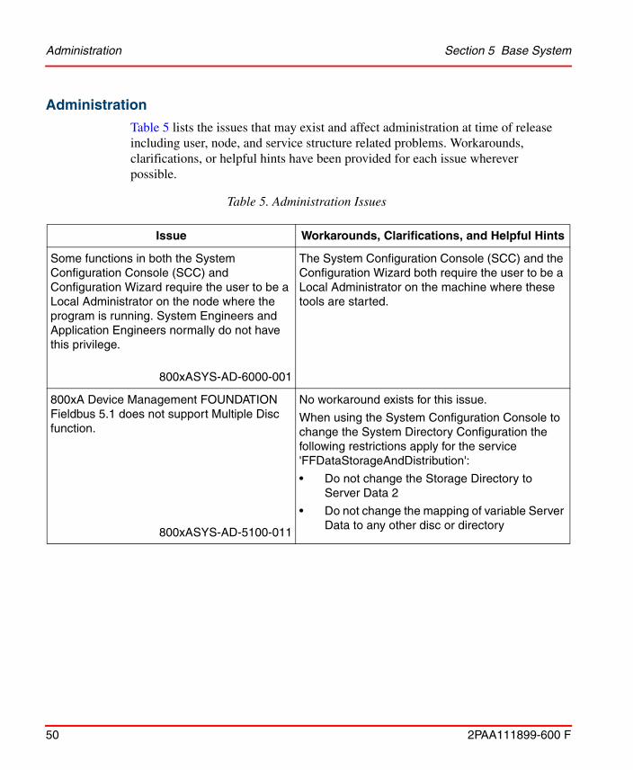
Administration
Table 5 lists the issues that may exist and affect administration at time of release including user, node, and service structure related problems. Workarounds, clarifications, or helpful hints have been provided for each issue wherever possible.
Table 5. Administration Issues
Issue Workarounds, Clarifications, and Helpful Hints
Some functions in both the System Configuration Console (SCC) and Configuration Wizard require the user to be a Local Administrator on the node where the program is running. System Engineers and Application Engineers normally do not have this privilege.
800xASYS-AD-6000-001
The System Configuration Console (SCC) and the Configuration Wizard both require the user to be a Local Administrator on the machine where these tools are started.
800xA Device Management FOUNDATION Fieldbus 5.1 does not support Multiple Disc function.
800xASYS-AD-5100-011
No workaround exists for this issue.
When using the System Configuration Console to change the System Directory Configuration the following restrictions apply for the service 'FFDataStorageAndDistribution':
• Do not change the Storage Directory to Server Data 2
• Do not change the mapping of variable Server Data to any other disc or directory

Section 5 Base System Administration
2PAA111899-600 F 51
There will be an unexpected System Alarm generated when any Service Provider is not in operational state.
System Alarms like the following can appear:
“Service Provider X on Y operational” even though the service provider has been operational all the time.
800xASYS-AD-5000-002
A Service provider is operational when it is in the state Service or Standby.
There are however some situations where system alarms that were not expected might appear:
• When a server is restarted in a redundant system, Service Providers on other servers might enter Synchronizing state and where System Alarms are generated.
• When an Aspect Server is disconnected completely from the network, System Alarms for Service Providers on other servers might appear when the server is reconnected. These alarms are generated because the disconnected Aspect Server lost contact with other providers in the system. The alarms do not necessarily mean that the Service Providers were down.
After a node has been added to or removed using the Configuration Wizard; the node may not be visible in the System Status viewer.
800xASYS-AD-5000-044
It is recommended to restart all nodes in a system after a node has been added to or removed using the Configuration Wizard.
Table 5. Administration Issues (Continued)
Issue Workarounds, Clarifications, and Helpful Hints
Configuration Section 5 Base System
52 2PAA111899-600 F
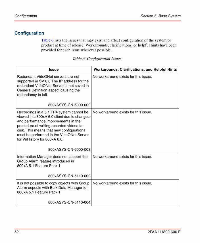
Configuration
Table 6 lists the issues that may exist and affect configuration of the system or product at time of release. Workarounds, clarifications, or helpful hints have been provided for each issue wherever possible.
Table 6. Configuration Issues
Issue Workarounds, Clarifications, and Helpful Hints
Redundant VideONet servers are not supported in SV 6.0 The IP address for the redundant VideONet Server is not saved in Camera Definition aspect causing the redundancy to fail.
800xASYS-CN-6000-002
No workaround exists for this issue.
Recordings in a 5.1 FP4 system cannot be viewed in a 800xA 6.0 client due to changes and performance improvements in the procedure of writing recorded videos to disk. This means that new configurations must be performed in the VideONet Server for VnHistory for 800xA 6.0.
800xASYS-CN-6000-003
No workaround exists for this issue.
Information Manager does not support the Group Alarm feature introduced in 800xA 5.1 Feature Pack 1.
800xASYS-CN-5110-002
No workaround exists for this issue.
It is not possible to copy objects with Group Alarm aspects with Bulk Data Manager for 800xA 5.1 Feature Pack 1.
800xASYS-CN-5110-004
No workaround exists for this issue.

Section 5 Base System Configuration
2PAA111899-600 F 53
It is not possible to browse for Alarm Conditions on objects from PLC Connect, while configuring Group Alarm and Alarm Hiding.
800xASYS-CN-5110-005
The Alarm Conditions can be manually specified.
When performing an import of a library, subentities that do not exist in the system will be imported even if the user selects No for the overwrite question of the library.
800xASYS-CN-5020-008800xASYS-CN-5101-004
Manually delete the entities and subentities that should not be imported in the Import/Export tool before performing the import.
During network disturbances the System Status Viewer can show wrong status for services when monitoring the Service Structure, even if the system is working correctly.
The Tray icon can also show the wrong status in this situation.
800xASYS-CN-5000-018
When the network is stable again bring up a new System Status Viewer.
Table 6. Configuration Issues (Continued)
Issue Workarounds, Clarifications, and Helpful Hints

Operation Section 5 Base System
54 2PAA111899-600 F
Operation
Table 7 lists the issues that may exist and affect operation of the system or product at time of release. Workarounds, clarifications, or helpful hints have been provided for each issue wherever possible.
Table 7. Operational Issues
Issue Workarounds, Clarifications, and Helpful Hints
In Process Graphics (PG2) the expression function LogicalColorFromName require that at least one parameter is dynamic. If no parameter is dynamic the default color will be used. This problem is introduced in 6.0.
800xASYS-OL-6000-004
As a workaround it is possible to create an expression variable and put the static string as a value of the expression variable. Then use the expression variable in the expression instead of the static string. This error will be corrected in next revision of the product.
Presets cannot be used in the "Camera View" aspect even if they are saved in the faceplate.
800xASYS-OL-6000-003
No workaround exists for this issue.
The AutoPopup property of RealDew input item:
• pops up correctly when the configured condition is true.But it does not popup when clicking at the hosting item.
• it is possible to enter a value in the invoked faceplate using the keyboard the first time the autopopup pops up. It is not possible to enter any value by using the keyboard the second time it pops up. But the up/down buttons to the right in the dew work.
800xASYS-OL-6000-001
No workaround exists for this issue.

Section 5 Base System Operation
2PAA111899-600 F 55
Aspect link with previous display indication shows wrong indication for quad workplace.
800xASYS-OL-5110-030
Use different panel layout for each screen. The pane identities and pane names should be unique within the workplace.
Navigation hot keys do not work with default workplaces in the Workplace Structure.
800xASYS-OL-5110-033
No workaround exists for this issue.
In 1oo2 redundant systems, client nodes with affinity set to the non-master Aspect Server might lose the ability to launch new workplaces or operate from existing workplaces when the Aspect Servers are reconnected after being disconnected due to network failure.
800xASYS-OL-5101-005
Restart the non-master Aspect Server when both Aspect Servers are running and in service state. When the non-master Aspect Server is running in service state, restart the clients connected to the newly restarted Aspect Server.
Engineering tools like Control Builder M, IO Allocation Tool, and Bulk Data Manager opens in the background when launched from the Workplace application.
800xASYS-OL-5100-010
Modify the windows registry setting "ForegroundLockTimeout" located at HKCU\Control Panel\Desktop to “0”. The default value is '200000' (hex 0x00030d40). This setting will cause all applications to be launched in the foreground.
Note: It is recommended to perform the setting only on Engineering Client nodes. This is a per user setting and requires a restart of the machine.
Table 7. Operational Issues (Continued)
Issue Workarounds, Clarifications, and Helpful Hints

Instruction Manual Changes Section 5 Base System
56 2PAA111899-600 F
Instruction Manual Changes
Table 8 lists the issues that exist in the instruction manuals that have not been corrected since the previous version. A brief description of the correction has also been given wherever possible.
Engineering tools, like the Import/Export tool or the Deploy tool can get more contents than expected when the include dependencies option is used.
800xASYS-OL-5010-013
When the include dependencies option is used, be sure to check the contents before the operation is performed, i.e. before pushing the Deploy button etc. For Import/Export it is also recommended to check the file on what actually got exported.
Another solution is to include dependencies manually from the dependency list (not using the include dependencies option), i.e. right click on a dependent item and select Add item for each item.
Table 8. Instruction Manual Changes
Issue Workarounds, Clarifications, and Helpful Hints
Information related to PC, Network and Software Monitoring (PNSM) missing in the table provided in the section Appendix A System Alarm and Event Messages in 800xA 5.1 Operations (3BSE036904-510*).
800xAPNS-MC-5101-021
Add the following information in the table.
Component: ITPNSMMonitoring(PC, Network software and monitoring)
Message Description: Error:%MessageDescription%
Extended Description: PC, Network software and monitoring Error
Message Description:%MessageDescription%
Extended Description: PC, Network software and monitoring Information
Table 7. Operational Issues (Continued)
Issue Workarounds, Clarifications, and Helpful Hints

2PAA111899-600 F 57
Section 6 System Services
Known ProblemsThis section details the Known Problems for the System Services that exist in the system at the time of release.
Central Licensing ServiceTable 9 lists the operational issues that may exist and affect the system or product at time of release. Workarounds, clarifications, or helpful hints have been provided for each issue wherever possible.
Table 9. Operational Issues
Issue Workarounds, Clarifications, and Helpful Hints
If an 800xA system is created with name containing special characters like & ‘ampersand’, then the temporary license message pops up.
800xASRV-OL-5100-009
Do not use special characters.
The License Usage Aspect in the system is not environment aware. This will generate differences in the environment differences tool.
800xASRV-OL-5100-010
Ignore this error as this would not impact the Central Licensing Service functionality.

Diagnostics Collection Tool Section 6 System Services
58 2PAA111899-600 F
Diagnostics Collection Tool
Configuration
Table 10 lists the issues that may exist and affect the configuration of the system or product at time of release. Workarounds, clarifications, or helpful hints have been provided for each issue wherever possible.
Operation
Table 11 lists the issues that may exist and affect the operation of the system or product at time of release. Workarounds, clarifications, or helpful hints have been provided for each issue wherever possible.
Table 10. Configuration Issues
Issue Workarounds, Clarifications, and Helpful Hints
It might not be possible to perform Collect, Explore or Analyze Data in case of the error “Error: Failed to contact Node Interrogator”.
800xASRV-CN-5020-007
This error indicates that Node Interrogator Service is not running. To start this service:
1. Select ABB Node Interrogator service in Control Panel > Administrative Tools > Services.
2. Select Start from Action menu. This starts the Node Interrogator service.
3. Re-open Diagnostics Collection Tool.

Section 6 System Services Structured Data Logger
2PAA111899-600 F 59
Structured Data Logger
Configuration
Table 12 lists the issues that may exist and affect the configuration of the system or product at time of release. Workarounds, clarifications, or helpful hints have been provided for each issue wherever possible.
Table 11. Operational Issues
Issue Workarounds, Clarifications, and Helpful Hints
While using the DCT, it is observed that the Node Interrogator Service is gradually utilizing the memory and there by resulting in System.OutOfMemoryException.
800xADCT-OL-5110-006
Node Interrogator service has to be restarted.
To restart:
1. Select ABB Node Interrogator service in Control
Panel > Administrative Tools > Services.
2. Select Restart from the Action menu. This restarts the Node Interrogator service.
3. Re-open the Diagnostics Collection Tool.
It is rarely observed that the collection or download does not complete after several hours for large Process dumps or WER dumps from nodes in the network.
800xASRV-OL-5100-002
Close the collection or download.
Ensure to collect dumps for less number of processes using User Dump Plug-in.
Use specific date option in WER Plug-in to collect dumps for a specific period or date.

Configuration Section 6 System Services
60 2PAA111899-600 F
Table 12. Configuration Issues
Issue Workarounds, Clarifications and Helpful Hints
An export (with dependencies) of SDL Log aspects does not automatically include SDL Log Type aspects.
800xASDL-CN-5020-001
Manually export the SDL Log Type aspects used by the SDL Log aspect.

2PAA111899-600 F 61
Section 7 Engineering Studio
Known ProblemsThis section details the Known Problems for Engineering Studio that exist in the system at the time of release.
Operation
Table 13, Table 14, Table 15, Table 16, Table 17 and Table 18 lists the issues that may exist and affect operation of the system or product at time of release. Workarounds, clarifications, or helpful hints have been provided for each issue wherever possible.
Table 13. Operational Issues
Issue Workarounds, Clarifications, and Helpful Hints
The AUTOCAD integration for Document Manager is not available.
800xAENS-OL-6000-001
No workaround exists for this issue.
Document Manager does not support: Microsoft Word file of .docx and Microsoft Excel file of .xlsx formats.
800xAENS-OL-6000-004
No workaround exists for this issue.

Operation Section 7 Engineering Studio
62 2PAA111899-600 F
Opening and closing a Document Manager aspect such as Function Diagram Document aspect does not release ENG_BASE license.
800xAENS-OL-5105-002
Close and re-open the Engineering workplace which releases the ENG_BASE license.
Table 14. Bulk SPL Operational Issues
Issue Workarounds, Clarifications, and Helpful Hints
In a sequence overview diagram, Placing the steps/transitions beyond the T column on the horizontal axis in a sequence overview diagram and importing it to Bulk SPL template, results in placing these steps/transition beyond the template range.
800xAENS-OL-5130-003
Insert new columns in the template equivalent or more than the exceeded number of columns.
User is unable to write any logic inside the detailed sheet of the BulkSPL template because the N action does not expand.
800xAENS-OL-6000-002
No workaround exists for this issue.
While deleting the number of inputs to the logic operand in the SPL_Detailed sheet deletes the inputs, it retains the number of associated inputs in the operand resulting in an error while writing to 800xA.
800xAENS-OL-5130-004
Delete the Operand along with all the inputs and reinsert.
Table 13. Operational Issues (Continued)
Issue Workarounds, Clarifications, and Helpful Hints

Section 7 Engineering Studio Operation
2PAA111899-600 F 63
First time opening of a large sequence diagram, created using Bulk SPL template may take some time.
800xAENS-OL-5130-005
No workaround exists for this issue.
Table 15. Function Designer, Operational Issues
Issue Workarounds, Clarifications, and Helpful Hints
In Function Diagrams if an object like Control Module or Function Block is changed from Aspect Object to Symbol Object or vice versa via the context menu, in some instances an error is displayed:
Concurrent modification of aspect is not allowed.
800xAENS-OL-6000-003
Acknowledge the message and generate configuration data for the diagram.
On subscribing for live data, animation of links in the transition of a Function Diagram with a sequence is inconsistent.
800xAENS-OL-6000-005
No workaround exists for this issue.
Table 14. Bulk SPL Operational Issues
Issue Workarounds, Clarifications, and Helpful Hints

Operation Section 7 Engineering Studio
64 2PAA111899-600 F
Select the Normal Position check box in the CBM_SignalParameter aspect of a DIS signal. Allocate it to channel 12 of a DI830 device through the Write Allocation into CBM operation from the IO Allocation dialog. The Normal Position detail is not updated in Control Builder M.
800xAENS-OL-5024-004
Perform the following in Control Builder M after allocating DI830 device through the Write Allocation into CBM operation from the IO Allocation dialog:
1. Right-click DI830 and click Reservation.
2. Double-click DI830 and edit the value of the Normal Position attribute for channel 12.
3. Click Save.
If a modified Function Diagram is closed without saving, it will execute a consistency check once when the specific diagram is reopened. Depending on the amount of changes and the size of the diagram, this consistency check may take considerable time.
This behavior also occurs while working with large sized diagrams when the Insufficient memory error message appears.
800xAENS-OL-5024-016
While working with large sized Function Diagrams or while performing large amount of changes, it is recommended to save the diagrams frequently.
In some rare instances, online values of Function Designer are not displayed on diagram references in child diagrams.
800xAENS-OL-5024-020
Reopening the diagram will display the online values.
In some instances, cut paste of Sequence 2D across diagrams may result in inconsistency in sequence.
800xAENS-OL-5025-017
No workaround exists for this issue.
Table 15. Function Designer, Operational Issues (Continued)
Issue Workarounds, Clarifications, and Helpful Hints

Section 7 Engineering Studio Operation
2PAA111899-600 F 65
In some instances, while subscribing live data in the Function Diagrams, navigating from sender to receiver diagram and performing graphical changes by selecting group of objects leads the system to stop responding.
800xAENS-OL-5100-004
While subscribing live data, do not perform any graphical changes by selecting group of objects in the Function Diagrams.
The diagram state indicated in the traffic light symbol of the status bar of the Function Designer window shows incorrect status ( ) while using Write Allocation into CBM from the IO Allocation dialog.
800xAENS-OL-5100-007
Regenerate configuration data after performing Write allocation to CBM from the IO Allocation dialog to obtain the correct diagram state in the traffic light symbol.
Configuring a selection branch after a simultaneous sequence results in error during generation of Configuration Data.
800xAENS-OL-5100-009
Simultaneous sequences need to end with a transition-step-transition configuration, before using a selection branch in sequences.
Graphical representation of the complex sequences configured through Function Diagrams may differ in SFC Viewer and Control Builder Viewer.
800xAENS-OL-5100-011
This does not affect the flow of the logic.
Table 15. Function Designer, Operational Issues (Continued)
Issue Workarounds, Clarifications, and Helpful Hints

Operation Section 7 Engineering Studio
66 2PAA111899-600 F
In the Function Diagram, copy / paste of an existing group of connected blocks with system functions and diagram references results in error messages during generation of Configuration Data.
800xAENS-OL-5100-010
Navigate to the specific errors and correct it manually.
The following limitations exist in the caching enabled system:
1. User cannot rename steps / transitions in a sequence diagram.
2. After converting an aspect object to symbol object, closing and reopening the diagram without saving creates a dummy object.
3. Working with diagram references without saving the Function Diagram may lead to the following limitations:
- The error message “Industrial IT has rejected this operation” appears when user tries to delete the output reference.
- The connection between the references appears to exist in the form of yellow references, though there are no connections.
- When user tries to disconnect the variable, the following error message appears: “System Null Error”.
800xAENS-OL-5100-013
1. Prior to setting CachingEnabled to True, create an SFC overview diagram with required names assigned to steps and transitions.
2. Always save the respective Function Diagrams while:
- converting an aspect object to symbol object.
- working with diagram references.
Table 15. Function Designer, Operational Issues (Continued)
Issue Workarounds, Clarifications, and Helpful Hints

Section 7 Engineering Studio Operation
2PAA111899-600 F 67
Creation of several thousands of Function Diagrams using Bulk Data Manager may fail.
Bulk Data Manager progress bar may disappear while updating several hundred objects although the operation is in progress.
800xAENS-OL-5100-015
1. Set VarCrossRef_Include_DiagRef to False before performing any bulk operations.
For more information, refer to System 800xA Engineering Studio Function Designer (3BDS011224*).
2. If several thousands of Function Diagrams need to be created using Bulk Data Manager, then split the Function Diagrams into manageable quantities (less than thousands) and create them separately using Bulk Data Manager.
In some instances, Function Designer and Control Builder M stop responding during generation of Configuration Data when Control Builder M is online.
800xAENS-OL-5100-016
1. Avoid performing configuration data generation while Control Builder M is in online mode.
2. In Control Builder M, always set system variable SaveColdRetainOnOfflineTransfer to False in the following path: Tools > Setup > Station > Application.
3. If Control Builder M has stopped responding, perform the following:
a. Open the Windows Task Manager and select the Processes tab.
b. Click Image Name to sort the column.
c. Select the controlbuilderpro.exe process.
d. Click End Process.
e. Click Yes in the Task Manager Warning dialog box to end the process.
f. Restart the workplace and regenerate configuration data for the specific Function Diagram.
Table 15. Function Designer, Operational Issues (Continued)
Issue Workarounds, Clarifications, and Helpful Hints

Operation Section 7 Engineering Studio
68 2PAA111899-600 F
Function Diagrams linked through diagram references and opened in workbook mode may have the following issues.
Scenario 1:
1. Select either Subscribe for Live Data for Connected Output Ports or Subscribe for Live Data Output Ports for a Function Diagram.
2. Double-click and select the Diagram in the next tab and select either Subscribe for Live Data for Connected Output Ports or Subscribe for Live Data Output Ports.
The values are not displayed for the current Function Diagram.
Scenario 2:
Select either Subscribe for Live Data for Connected Output Ports or Subscribe for Live Data Output Ports for any page of a Function Diagram where the source page connector is available.
The color indication for the Boolean values is visible in the sink page connector though that specific page is not subscribed by the user.
Scenario 3:
Select Subscribe for Live Data for Connected Output Ports for the Function Diagram. The color indication for the inout ports of the Boolean datatype is not correctly displayed based on the value transferred between the ports.
800xAENS-OL-5100-018
Scenario 1:
In the specific Function Diagram, deselect and select Subscribe for Live Data for Connected Output Ports or Subscribe for Live Data Output Ports again to display the values.
Table 15. Function Designer, Operational Issues (Continued)
Issue Workarounds, Clarifications, and Helpful Hints

Section 7 Engineering Studio Operation
2PAA111899-600 F 69
If a child instance of any function block type is selected during the Change Type operation, the Engineering Workplace does not respond when this diagram is opened next time.
For example, this behavior occurs if a child instance under any function block type is selected during the Change Type operation of a particular function block which is a symbol object.
800xAENS-OL-5100-019
Ensure that the correct object type is selected when the Change Type option is used.
The information about external references to Communication Variable is not available in the Function Diagram, for the scenario explained below:
Communication Variable (CV1) is declared in a Function Diagram and this diagram is allocated to an application, which also contains Single Control Modules/Programs with the same communication variable (CV1). In this case, the communication variable in the diagram does not indicate the external reference information.
800xAENS-OL-5100-021
This does not affect the functionality of Communication Variables.
Table 15. Function Designer, Operational Issues (Continued)
Issue Workarounds, Clarifications, and Helpful Hints

Operation Section 7 Engineering Studio
70 2PAA111899-600 F
In a sequence block, if different actions in multiple steps are having the same name, they always point to the same action when ‘SFC Overview’ is used to navigate through the actions.
800xAENS-OL-5100-022
Ensure that unique action names are followed across a sequence.
Consider a Function Diagram containing a page connector. If the diagram is copy-pasted, and the page connector is renamed in the copied diagram, then the position and size of the page connector changes in respect to the original diagram.
800xAENS-OL-5101-005
No workaround exists for this issue.
Copy and paste the default AND (bool) block in a Transition of a sequential diagram. Create a logic using the pasted AND block. Save and close the diagram. While reopening the diagram, the connections to the pasted AND block are lost.
800xAENS-OL-5101-009
Add a new AND (bool) block using Insert menu.
When a Function Setting ConfigDataForSFC is set as true, on performing Configuration Data Generation, SFCXRefDataMapper aspect is created for all diagrams by default.
800xAENS-OL-5101-016
No workaround exists for this issue.
Table 15. Function Designer, Operational Issues (Continued)
Issue Workarounds, Clarifications, and Helpful Hints

Section 7 Engineering Studio Operation
2PAA111899-600 F 71
Copying a Function Diagram with internal connections sources leads to error. If the setting is set to Make new unique connection, sinks and sources are renamed and connected to the original source.
800xAENS-OL-5102-005
No workaround exists for this issue.
Revert operation in LEG does not clean up production environment from the Function Diagram.
This is because, the Function aspect is added in the Function Blocks of the user defined library. The library is then used in the Function Diagram and the application is sent through LEG.
800xAENS-OL-5102-011
Changes to User Defined libraries (Adding Function aspect) must be done in the Production Environment only while using LEG for Function diagrams.
In some instances, Windows Event Viewer displays the Side by Side error.
800xAENS-OL-5102-013
This error message can be ignored.
While inserting or editing the name for function block in the SCM based Function Diagram, text box with blue background is displayed.
800xAENS-OL-5103-001
Click outside the text box to view the edited text.
Table 15. Function Designer, Operational Issues (Continued)
Issue Workarounds, Clarifications, and Helpful Hints

Operation Section 7 Engineering Studio
72 2PAA111899-600 F
In a sequence step, if a diagram reference is connected to a variable of structure data type, logic is not transferred to the Control Builder M.
800xAENS-OL-5103-002
No workaround exists for this issue.
In Function Diagram editor, if two ports of same or different function block types / control module types with same data type are connected directly without creating a variable, the resulted connection is not visible in Control Builder diagram editor.
800xAENS-OL-5103-005
Insert a variable of same data type and connect both the ports.
In the Functional Structure, if a Function Diagram is inserted under another object then the icon of the inserted Function Diagram does not change to indicate that it is an inserted object. Deletion of the inserted Function Diagram results in the deletion of the original Function Diagram
800xAENS-OL-5104-006
No workaround exists for this issue.
If there are multiple blocks in a Function Diagram with same port name and datatype, and if variables are created connected to these ports by a right-click on the port, then the variables are assigned a name, same as the port name and it results in multiple invocation of the variable.
800xAENS-OL-5104-007
No workaround exists for this issue.
Table 15. Function Designer, Operational Issues (Continued)
Issue Workarounds, Clarifications, and Helpful Hints

Section 7 Engineering Studio Operation
2PAA111899-600 F 73
In some instances, string connected to a port of user defined Function Block, may not be passed to Control Builder M on generation of Configuration Data.
800xAENS-OL-5104-010
No workaround exists for this issue.
In a Function Diagram width of blocks like Control Modules is adjusted to suit for text scaling when opening with different screen resolutions. This may result in truncation of Name and Description of blocks.
800xAENS-OL-5104-019
Re-write the Name and Description using Bulk Data Manager.
Repetitive opening of a Function Diagram that is pasted using Paste Special function may result in loss of Function blocks, Control Builder M signals etc. in the Function Diagram.
Product Bulletin ID: 9ARD134783-213800xAENS-OL-5104-022
Do not use Paste Special for copy-paste of Function Diagrams. Instead use Paste.
Connecting MBRead output port of AnyType datatype, to an input port of Control Module/ Function Block of any datatype, results in error on generating Configuration Data.
800xAENS-OL-5104-025
No workaround exists for this issue.
Table 15. Function Designer, Operational Issues (Continued)
Issue Workarounds, Clarifications, and Helpful Hints

Operation Section 7 Engineering Studio
74 2PAA111899-600 F
If a Diagram Variable is deleted from a Function Diagram which has multiple Diagram Input References, then after Analyze and View Difference, the same Diagram Variable is wrongly displayed as marked for deletion in several un-connected MMS Receiver Diagrams.
800xAENS-OL-5140-011
No workaround exists for this issue.
In rare scenarios "Aes Application Variable Table" aspect of an Application may have inconsistencies.
800xAENS-OL-5140-014
No workaround exists for this issue.
If Paste-rename, if performed from Functional Structure then all the child objects are not populated in the list.
800xAENS-OL-5105-018
No workaround exists for this issue.
In some instances on performing a change type for a Function Block or Control Module the labels are not updated.
800xAENS-OL-5105-006
No workaround exists for this issue.
Timestamp of an Allocatable Group aspect for a Function Diagram is wrongly updated due to changes in daylight saving.
800xAENS-OL-5105-020
No workaround exists for this issue.
Performing a change type for a variable with initial value in Function Designer and generating configuration data results in an error.
800xAENS-OL-5105-008
No workaround exists for this issue.
Table 15. Function Designer, Operational Issues (Continued)
Issue Workarounds, Clarifications, and Helpful Hints

Section 7 Engineering Studio Operation
2PAA111899-600 F 75
Upload of Init Values of Control Properties aspect to Function Designer does not work.
800xAENS-OL-5105-009
No workaround exists for this issue.
On instantiating Signal Groups in SCM based Function Diagrams, error messages are displayed on generation of Configuration Data.
800xAENS-OL-5105-017
No workaround exists for this issue.
Select all and delete of multiple Diagram References in a Function Diagram fails with the following error:
Industrial IT 800xA rejected this Action
800xAENS-OL-5105-010
Delete components individually
Following issues exist for updating Diagram references using BDM templates:
• Description of Diagram References is not updated while updating using "BDM_DiagramRef_Var_Adv" template.
• Existing description of Diagram References is deleted while updating using "BDM_DiagramRef_Var_Basic" template.
800xAENS-OL-5105-013
No workaround exists for this issue.
Table 15. Function Designer, Operational Issues (Continued)
Issue Workarounds, Clarifications, and Helpful Hints

Operation Section 7 Engineering Studio
76 2PAA111899-600 F
In a Function Diagram, copy of a diagram reference with its valid pin connected to blocks, results in incorrect connection to the valid pin of copied Diagram Reference.
800xAENS-OL-5105-016
No workaround exists for this issue.
Valid pin of a Communication Variable, used in a SCM based Function Diagram does not update correct status of Inter Application/Controller Communication
800xAENS-OL-5105-028
No workaround exists for this issue.
Table 16. IO Allocation, Operational Issues
Issue Workarounds, Clarifications, and Helpful Hints
Scaling of frequency value to process unit is set by the 'Min' & 'Max' values provided in the 'Properties' tab of pulse boards (e.g: DP820, DP840) in Control Builder M.
Users are unable to configure this through IO Allocation tool.
800xAENS-OL-5100-006
No workaround exists for this issue.
Allocation of Control Builder M Signals instantiated in Function Diagrams, to certain Profibus devices and performing Configuration Data Generation may result in the wrong traffic light status
800xAENS-OL-5104-023
No workaround exists for this issue.
Table 15. Function Designer, Operational Issues (Continued)
Issue Workarounds, Clarifications, and Helpful Hints

Section 7 Engineering Studio Operation
2PAA111899-600 F 77
The min-max values and engineering unit details of the de-allocated variable are not getting cleared in Control Builder M IO editor.
800xAENS-OL-5103-009
No workaround exists for this issue.
If some channels are connected to variables in Control Builder M and others are allocated through I/O allocation, this may lead to Inconsistency in generated data.
800xAENS-OL-5103-020
No workaround exists for this issue.
If the user deletes an unallocated Function Diagram having FF proxy object with variables allocated to CI860 board, then the variables are not getting deleted.
800xAENS-OL-5130-002
Delete the allocated Function Diagram.
IO Allocation tool stops responding when it is invoked from AC800M controller in Control Structure.
800xAENS-OL-5104-033
No workaround exists for this issue.
While configuring property mapping by adding a New PropertyMap on the IO Mapping aspect, the following error message appears and no modifications happen: Failed: Attempt to modify read only node
800xAENS-OL-5105-003
No workaround exists for this issue.
Table 16. IO Allocation, Operational Issues (Continued)
Issue Workarounds, Clarifications, and Helpful Hints
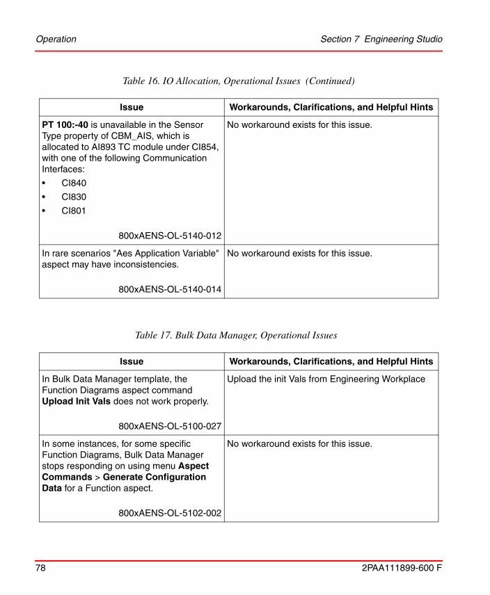
Operation Section 7 Engineering Studio
78 2PAA111899-600 F
PT 100:-40 is unavailable in the Sensor Type property of CBM_AIS, which is allocated to AI893 TC module under CI854, with one of the following Communication Interfaces:
• CI840
• CI830
• CI801
800xAENS-OL-5140-012
No workaround exists for this issue.
In rare scenarios "Aes Application Variable" aspect may have inconsistencies.
800xAENS-OL-5140-014
No workaround exists for this issue.
Table 17. Bulk Data Manager, Operational Issues
Issue Workarounds, Clarifications, and Helpful Hints
In Bulk Data Manager template, the Function Diagrams aspect command Upload Init Vals does not work properly.
800xAENS-OL-5100-027
Upload the init Vals from Engineering Workplace
In some instances, for some specific Function Diagrams, Bulk Data Manager stops responding on using menu Aspect Commands > Generate Configuration Data for a Function aspect.
800xAENS-OL-5102-002
No workaround exists for this issue.
Table 16. IO Allocation, Operational Issues (Continued)
Issue Workarounds, Clarifications, and Helpful Hints

Section 7 Engineering Studio Operation
2PAA111899-600 F 79
Saving the changes that are made using the filter option on the Bulk Data Manager templates result in errors (for example, “Source object not found “).
800xAENS-OL-5100-020
Avoid using the filter option on Bulk Data Manager templates.
Bulk Data Manager operations with Microsoft Office 2013 leak Graphic Device Interface (GDI) objects. Due to this, Microsoft Excel may stop responding after the upper limit of GDI objects (10000) is reached.
800xAENS-OL-5105-023
No workaround exists for this issue.
In some instance, on performing Configuration Data Generation in Bulk Data Manager, following error message is displayed:
Identifier invalid or to long.
800xAENS-OL-5102-004
No workaround exists for this issue.
In some instances, while working with Bulk Data Manager, on selection of Min Path from the Advanced menu instead of Full Path, may cause Microsoft Excel to stop responding.
800xAENS-OL-5104-001
Use Full Path instead of Min Path from the Advanced menu of Bulk Data Manager.
Table 17. Bulk Data Manager, Operational Issues (Continued)
Issue Workarounds, Clarifications, and Helpful Hints

Operation Section 7 Engineering Studio
80 2PAA111899-600 F
If BDM_DiagramRef_Var_Adv.xlsx template is used to update multiple attributes which are separated by separators other than space, for instance comma (,), semi-colon (;), of Global / Communication variables declared in Function Diagrams, then no attributes are transferred to Control Builder M on generating Configuration Data.
800xAENS-OL-5105-001
Use only space as the separator between multiple attributes.
While working on Bulk Data Manager to copy/create 800xA objects with Microsoft Excel 2013, leaks occur in Graphic Device Interface (GDI) objects. Due to this, Microsoft Excel may stop responding after GDI objects reach the maximum limit of 10000.
800xAENS-OL-5105-0023
Split the Bulk Data Manager copy/create into manageable blocks and restart Microsoft Excel after every transfer.
Table 18. Script Manager, Operational Issues
Issue Workaround, Clarifications, and Helpful Hints
Attach Debugger icon is not functional in Script manager.
800xAENS-OL-5103-030
No workaround exists for this issue.
Table 17. Bulk Data Manager, Operational Issues (Continued)
Issue Workarounds, Clarifications, and Helpful Hints

2PAA111899-600 F 81
Section 8 AC 800M
IntroductionThis section provides information on safety and compatibility of the system. It also enumerates known problems encountered in the final testing of this product release.Where possible the document identifies workarounds that help overcome the problem. The section also contains additional notes that may be valuable to customers and service personnel working with the product.
SafetyFor a complete list of AC 800M safety related warnings, for this release, see System 800xA Safety AC 800M High Integrity Safety Manual (3BNP004865*).
For information on SIL (Safety Integrity Level) conformance according to IEC 61508 or other applicable safety standards, refer to the manual System 800xA Safety AC 800M High Integrity Safety Manual (3BNP004865*) and 800xA - Safety, Reliability and Availability Data (3BSE034876*). Certified versions of the safety manuals are stated in TÜV Certification Report, Annex A (3BSE074100).
The term Control Builder refers to Control Builder M Professional.The term OPC Server refers to OPC Server for AC 800M.The term Modem refers to modems that are configured and controlled by a controller. It does not refer to modems that are transparent for the controller.The term Controller refers to a Process Automation (PA) Controller. If it is a High Integrity Controller, the text will say High Integrity or HI Controller.
In order to get the formal status of the safety certification of a 800xA Safety product (safety documentation, hardware and software components), refer to the latest version of the TÜV Certification Report, Annex A, ABB SolutionsBank or ABB Library (3BSE074100).
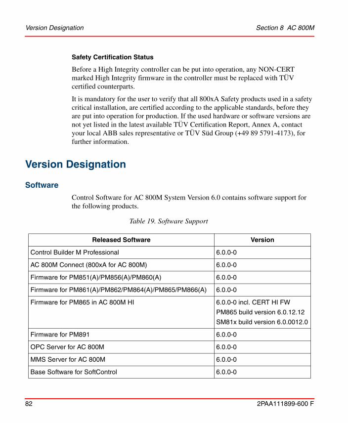
Version Designation Section 8 AC 800M
82 2PAA111899-600 F
Safety Certification Status
Before a High Integrity controller can be put into operation, any NON-CERT marked High Integrity firmware in the controller must be replaced with TÜV certified counterparts.
It is mandatory for the user to verify that all 800xA Safety products used in a safety critical installation, are certified according to the applicable standards, before they are put into operation for production. If the used hardware or software versions are not yet listed in the latest available TÜV Certification Report, Annex A, contact your local ABB sales representative or TÜV Süd Group (+49 89 5791-4173), for further information.
Version Designation
Software
Control Software for AC 800M System Version 6.0 contains software support for the following products.
Table 19. Software Support
Released Software Version
Control Builder M Professional 6.0.0-0
AC 800M Connect (800xA for AC 800M) 6.0.0-0
Firmware for PM851(A)/PM856(A)/PM860(A) 6.0.0-0
Firmware for PM861(A)/PM862/PM864(A)/PM865/PM866(A) 6.0.0-0
Firmware for PM865 in AC 800M HI 6.0.0-0 incl. CERT HI FW
PM865 build version 6.0.12.12
SM81x build version 6.0.0012.0
Firmware for PM891 6.0.0-0
OPC Server for AC 800M 6.0.0-0
MMS Server for AC 800M 6.0.0-0
Base Software for SoftControl 6.0.0-0

Section 8 AC 800M Hardware
2PAA111899-600 F 83
Hardware
This release supports:
• AC 800M (PM851(A), PM856(A), PM860(A), PM861(A), PM862, PM864(A), PM865, PM866(A) and PM891)
• AC 800M High Integrity (PM865, SM810/SM811)
Compatibility
Controller peer to peer communication is possible with other controllers running Version 2.x/x, 3.x/x, 4.x.x/x or 5.x.x/x by means of Access Variables.
Supported Versions
Online Upgrade Paths
Redundant AC 800M controllers can be upgraded with new firmware versions online. Online upgrade is initiated from Control Builder by a 9-step wizard, that describes the complete upgrading process. For more information, refer to the Maintenance and Trouble-Shooting section in System 800xA Control AC 800M Configuration (3BSE035980*) manual.
Online upgrade is supported from the controller versions listed in document 800xA Online upgrade and Co-existence, versions compatibility (3BSE080447) on ABB SolutionsBank. Note that this document is an aid document and before executing
Tool Routing Service for AC 800M 6.0.0-0
IP Config 6.0.7
Serial Firmware Upgrade 6.0.7
Some Hardware Modules may have to be exchanged to new hardware revisions. See Compatible Hardware Modules on page 85, for further information. Listed Hardware Modules must be of stated version/revision or higher.
Table 19. Software Support (Continued)
Released Software Version
Supported Versions Section 8 AC 800M
84 2PAA111899-600 F
online upgrade or co-existence for a safety system, check the valid safety certificate annex.
Supported Versions for Coexistence of Controller Versions
Coexistence is supported between the controller versions listed in document 800xA Online upgrade and Co-existence, versions compatibility (3BSE080447) on ABB SolutionsBank. Note that this document is an aid document and before executing online upgrade or co-existence for a safety system, check the valid safety certificate annex.

Section 8 AC 800M Compatible Hardware Modules
2PAA111899-600 F 85
Compatible Hardware ModulesThe Hardware Modules listed in Table 20 must be of the stated version/revision or higher.
Listed I/O Modules are included due to compatibility issues. For some other I/O Modules there is a recommendation about firmware and hardware versions for other reasons. See other relevant documentation regarding such reasons.
Firmware in all Hardware Modules must be upgraded to the delivered version. See Compatible Firmware on page 89.
Table 20. Compatible Hardware Modules
Module Required Version Recommended Version
PM851 PR:A
PM851A PR:A
PM856 PR:A PR:F
PM856A PR:A
PM860 PR:B PR:H
PM860A PR:B
PM861(Singular)
PR:B PR:L
PM861(Redundant)
PR:B(1) PR:L
PM861A(Singular)
PR:B PR:C
PM861A(Redundant)
PR:B with FPGA 1.2/1
-or-
PR:C
PR:C(2)
PM862 PR:A

Compatible Hardware Modules Section 8 AC 800M
86 2PAA111899-600 F
PM864 PR:B with FPGA 1.2/5
-or-
PR:C
PR:H
PM864A(Singular)
PR:B PR:C
PM864A(Redundant)
PR:B with FPGA 1.2/1
-or-
PR:C
PR:C(2)
PM865(Process Automation
Singular)
PR:C PR:D
PM865(Process Automation
Redundant)
PR:C with FPGA 2.0/0
-or-
PR:D
PR:D(3)
PM865(High Integrity)
PR:G
PM866 PR:B
PM866A PR:A
PM891 PR:A
SM810 PR:C
SM811 PR:A
CI853 PR:C(4)
CI854 PR:B
Index 01.00
PR:G
Index 01.03(5)
CI854A PR:D
Index 02.05
Table 20. Compatible Hardware Modules (Continued)
Module Required Version Recommended Version

Section 8 AC 800M Compatible Hardware Modules
2PAA111899-600 F 87
CI854B PR:A
CI855 PR:B PR:C(6)
CI856 PR:A PR:B(7)(8)
CI857 PR:B PR:C
CI858 PR:A
CI860 PR:C
Index 02.01
PR:H(9)
Index 04.00
CI865 PR:B
CI867 PR:A
CI868 PR:A
CI869 PR:D
CI871 PR:A
CI872 PR:B PR:D
CI873 PR:A
TB820V2 PR:A(10)
TB840 PR:J(11) PR:M
TB840A PR:A
DI830 PR: H(12) PR: K
DI831 PR: H(12) PR: K
DI885 PR:C
AI845 PR:F
AO845 PR:E PR:J
AO845A PR:A PR:C
Table 20. Compatible Hardware Modules (Continued)
Module Required Version Recommended Version

Compatible Hardware Modules Section 8 AC 800M
88 2PAA111899-600 F
DI880 PR:E PR:J
DO880 PR:F(13) PR:J
DP820(14) PR:A
AI880A(15) PR:B PR:F
BC810 PR:C(16) PR:E
BC820 PR:B(17)
200-APB12 1.6
200-ACN 1.4
200-IE8 B
200-OE4 B
LD 800DN PR:A
(1) No empty base plates are allowed on the CEX-bus when using less than PR:D.(2) PR:D or later supports online replacement of a defect RCU-cable in configurations with BC810.(3) PR:F or later supports online replacement of a defect RCU-cable in configurations with BC810.(4) Firmware Version 1.0.6.0 or later (2002-01-17) must be used.
Hardware revision PR:A and PR:B cannot be upgraded. Revision PR:C or newer must be used.(5) When using less than Index 01.01:
AC 800M may in some configurations not resume execution after a power fail.(6) Less than PR:C does not support firmware upgrade.(7) PR:B is required when using DSBC173A or TK575V112 I/O Connection Cable.
PR:A sometimes fails to start up.(8) CI856 must be upgraded to PR:D or later in order to support online upgrade.(9) PR:H or later supports Online Replacement and CI860 Redundancy.(10) TB820V2 PR:F or later is required when using DI818, DO818, DI828 or DO828.(11) PR:B1, D, and E can also be used.
When using PR:B1, D and E: The optical Modulebus on PM861(A) or PM864(A) must be disconnected from the backup CPU before it is powered up, in case the primary CPU is already running.When using PR:B1, D, E and J: SA supervision will report error on SB, and vice versa.
(12) PR:F can also be used.(13) Degraded Mode is supported with DO880 PR:G or newer.(14) PR:E or later is required if modulebus scan time is greater than 90 ms.
Table 20. Compatible Hardware Modules (Continued)
Module Required Version Recommended Version

Section 8 AC 800M Compatible Firmware
2PAA111899-600 F 89
Compatible FirmwareThe firmware in the Hardware Modules listed in Table 21 must be of stated label or version.
(15) The AI880A does not have the same key code as AI880. AI880 is no longer supported. PR:C is required for full HART support.
(16) PR:E or later is required in an AC 800M High Integrity.(17) PM866 PR:H or later is required when using BC820.
Table 21. Compatible Firmware
Module Label or Version
CI858(1)
(1) Not possible to upgrade from Control Builder.
FWCI858 1.0.0.2
CI801 1.2/3(2) (or later)
(2) CI801 Version 1.2/3 or later is required when using the added set of RTD sensors in AI830A. CI801 Version 1.3//0 or later is required when using AI815, AO815 and enhanced CJT functions in AI835A.CI801 Version 1.5/1 or later is required when using DI818, DO818, DI828 or DO828.
CI830 1.3/2(3)(4) (or later)
(3) CI830 versions less than 1.3/2 fail to set I/O to OSP in some situations.(4) CI830 Version 1.4/0 or later is required when using AI893 or DP840.
CI840(A) 3.0/2(5) (or later)
(5) CI840(A) Version 3.3/8 or later is required when using the added set of RTD sensors in AI830A. CI840(A) Version 4.0/1 or later is required when using AI815, AO815 and enhanced CJT functions in AI835A.CI840(A) Version 4.1/7 or later is required when using DI818, DO818, DI828 or DO828.
CI920 1.4.1 (or later)
CI920A 2.1.0
LD 800DN 1.04 (or later)

Included Library Version Section 8 AC 800M
90 2PAA111899-600 F
Included Library Version
Table 22. Hardware Libraries
Library Version of this release
ABBDrvFenaCI871HwLib 1.0-3
ABBDrvFpbaCI854HwLib 1.0-2
ABBDrvNpbaCI854HwLib 1.0-2
ABBDrvRetaCI871HwLib 1.0-6
ABBDrvRpbaCI854HwLib 1.0-2
ABBMNSiSCI871HwLib 1.0-6
ABBPnl800CI854HwLib 1.1-0
ABBPNQ22CI871HwLib 1.0-0
ABBProcPnlCI854HwLib 1.0-1
BasicHIHwLib 6.0-0
BasicHwLib 6.0-0
CI853SerialComHwLib 1.0-2
CI854PROFIBUSHwLib 2.11-25
CI855MB300HwLib 2.10-1
CI856S100HwLib 2.10-5
CI857InsumHwLib 2.10-6
CI858DriveBusHwLib 2.10-4
CI860FFHSEHwLib 2.11-1
CI865SattIOHwLib 2.10-3
CI867ModbusTcpHwLib 2.10-11

Section 8 AC 800M Included Library Version
2PAA111899-600 F 91
CI868IEC61850HwLib 3.10-16(1)
CI869AF100HwLib 2.10-1
CI871PROFINETHwLib 1.10-8
CI872MTMHwLib 2.10-1
CI873EthernetIPHwLib 2.10-10
COMLIHwLib 2.10-2
ModBusHwLib 2.10-8
ModemHwLib 1.0-0
PrinterHwLib 2.10-2
S200IoCI854HwLib 1.0-1
S200IoCI873HwLib 1.0-9
S3964HwLib 2.10-3
S800CI801CI854HwLib 1.4-0
S800CI830CI854HwLib 1.0-11
S800CI840CI854HwLib 1.4-0
S800IoModulebusHwLib 1.4-1
S900IoCI854HwLib 2.0-0(2)
SerialHwLib 2.10-2
TCPHwLib 1.10-4
UDPHwLib 1.10-0
(1) Version Compatibility - 2.20-0(2) Version Compatibility - 1.1-2
Table 22. Hardware Libraries
Library Version of this release

Included Library Version Section 8 AC 800M
92 2PAA111899-600 F
Table 23. Application Libraries
LibraryVersion of this
release
AlarmEventLib 1.7-1
BasicGraphicLib 1.4-1
BasicLib 1.8-2
BatchLib 1.4-1
COMLICommLib 1.5-1
ControlAdvancedLib 1.6-1
ControlBasicLib 1.4-2
ControlExtendedLib 1.5-1
ControlFuzzyLib 1.5-1
ControlObjectLib 1.4-1
ControlSimpleLib 1.4-1
ControlSolutionLib 1.4-1
ControlStandardLib 1.6-3
ControlSupportLib 1.5-5
FFHSECommLib 1.5.1
FireGasLib 2.6-1
GraphicSupportLib 1.3-0
GroupStartLib 1.6-1
IconLib 1.5-1
INSUMCommLib 1.4-1
IOCommLib 1.1-1
MB300CommLib 1.4-1

Section 8 AC 800M Included Library Version
2PAA111899-600 F 93
MMSCommLib 1.5.1
ModBusCommLib 1.5-1
ModBusTCPCommLib 1.4-1
ModemCommLib 1.4-1
MTMCommLib 1.3-1
ProcessObjBasicLib 2.6-3
ProcessObjDriveLib 1.6-2
ProcessObjExtLib 2.6-1
ProcessObjInsumLib 1.6-1
S3964CommLib 1.5-1
SattBusCommLib 1.5-1
SeqStartLib 1.4-1
SerialCommLib 2.3-1
SignalBasicLib 1.3-1
SignalLib 1.8-2
SignalSupportLib 1.3-1
SupervisionBasicLib 1.3-1
SupervisionLib 2.7-1
SupportLib 1.5-1
TCPCommLib 1.2-1
UDPCommLib 1.2-1
VMTLib 1.1-0
Table 23. Application Libraries
LibraryVersion of this
release

Installation of AC 800M HI Extension Section 8 AC 800M
94 2PAA111899-600 F
Installation of AC 800M HI Extension
AC 800M High Integrity
The firmware for PM865, SM810 and SM811 in AC 800M HI Extension 6.0.0-0, Build Id 6.0.11.12 included in the initial release of System Version 6.0 are not TÜV certified for operational use in a High Integrity Controller, and are marked as "NON-CERT". They are available for test and engineering purposes only.
The firmware for PM865, SM810 and SM811 must be replaced with the TÜV certified versions for operational use in a High Integrity Controller, see 3BSE074100, TÜV Certification Report, Annex A.
The updated firmware versions are available after installing the certified version of AC800M HI Extension for System Version 6.0.
The AC 800M HI Extension safety software and manuals are available in ABB Solutions Bank or ABB Library, 3BSE072981D6000, ABB Control Software for AC 800M High Integrity Controller Update version 6.0.0-0 zip-archive.
Step 1: Installation from ZIP-Archive
The Configuration Wizard shall be closed before installation to avoid resource locking of shared files during installation.
The System Configuration Console (SCC) shall be closed before running the AC 800M HI Extension Update bat file in Action 2.
If aspect system is running during installation there might be some warning messages that have to be accepted by selecting "Ignore" to continue.

Section 8 AC 800M Step 1: Installation from ZIP-Archive
2PAA111899-600 F 95
The Certified version shall be installed on all nodes where AC 800M HI Extension is installed in the system for visibility and configuration management reason. Execute the following steps for each node:1. Unzip the Control Software for 3BSE072981D6000, ABB Control Software
for AC 800M High Integrity Controller Update version 6.0.0-0 zip-archive, to a suitable folder on the local node.
2. On the computer to be updated run the unzipped AC 800M HI Extension Update.bat file as administrator, i.e. right-click the file and select "Run as administrator". Follow the instructions to exchange all relevant installation files for HI Extension on the local node.
3. Now there are two scenarios, depending on if the AC 800M HI Extension "NON-CERT" is installed or not. This can be checked in Windows "Programs and Features".
(a) If AC 800M HI Extension 6.0.0-0 NON-CERT is already installed:
(a1) Run the unzipped HIInstaller.exe for the AC 800M HI Extension pointed out by the executed bat file described in action 2. This will uninstall the NON-CERT version and install the certified version of AC 800M HI Extension.
(a2) Use "Configure System Task" in the System Configuration Console (SCC) to deploy 800xA for AC 800M and AC 800M HI Extension.
(a3) When installation is completed on all server nodes, run the System Extension Maintenance from the 800xA Configuration Wizard on one system Aspect Server to load or update the AC 800M HI Extension into the system.
(b) If AC 800M HI Extension 6.0.0-0 NON-CERT is not installed: Use "Configure System Task" in the System Configuration Console (SCC) to install the certified AC 800M HI Extension.

Step 2: Verification of Installation Section 8 AC 800M
96 2PAA111899-600 F
Step 2: Verification of Installation
Verify the installation by opening the library structure in Plant Explorer and verify that the library versions listed in these release notes are loaded into the system.
Also, go to Programs and Features in the Windows Control Panel and check that the following appears in the list.
• ABB AC 800M HI Extension 6.0.0-0, Version 6.0.12.12
• ABB AC 800M HI Instructions 6.0.0-0, Version 6.0.12.12
Step 3: Post Installation - AC 800M HI Controller firmware
The firmware of each AC 800M High Integrity controller (PM865, SM811 and SM810) needs to be updated to the certified firmware for the installation to be completed, either by Online Upgrade or manually, as follows:
Manual Update AC 800M High Integrity controller:
1. Start Control Builder, and select Tools > Maintenance > Remote System... > Show Firmware Information.
2. Update the firmware in PM865:
– Make sure to select the firmware version: 6.0.12.12
3. Update the firmware in SM810/SM811(s) if applicable.
– Make sure to select the firmware version: 6.0.0012.0.
4. Select Tools > Maintenance > Remote System... > Show Firmware Information and verify that all firmware has been properly updated.

Section 8 AC 800M Known Problems
2PAA111899-600 F 97
Known ProblemsThis section details the Known Problems for AC 800M that exist in the system at the time of release.
Installation
Table 24 lists issues that may exist and affect the installation and migration of the system or product at time of release. Workarounds, clarifications, or helpful hints have been provided for each issue wherever possible.
Administration
Table 25 lists the issues that may exist and affect system or product administration at time of release including user, node and service structure related issues and problems.Workarounds, clarifications, or helpful hints have been provided for each issue wherever possible.
All issues and problems categorized as Controller are valid for both the AC 800M and AC 800M High Integrity controllers.
Table 24. Installation Issues
Issue Workarounds, Clarifications, and Helpful Hints
PROFINET IO
Upgrade PROFINET IO Feature Pack
When doing the upgrade of PROFINET IO Feature Pack 1.2 to 800xA 6.0, some settings on CI871 get reset to default values. This affects Default Gateway, Red.Eth.recovery time and Watchdog factor.
800xACON-IN-5100-001
Check CI871 settings after upgrade and enter the previous values if settings are changed.

Administration Section 8 AC 800M
98 2PAA111899-600 F
Table 25. Administration Issues
Issue Workarounds, Clarifications, and Helpful Hints
Control Builder
Hardware tree is removed when changing product type
Hardware tree is empty when changing product type to or from AC 800M High Integrity.
800xACON-AD-5110-002
No workaround exists for this issue.
UDP and TCP protocols disappears in HW-tree if CPU type is changed
When changing CPU type for an AC 800M Controller, for example, from PM861 to PM891, the protocol objects UDPProtocol and TCPProtocol for UDP/TCP will be removed.
800xACON-AD-5110-001
The protocol objects UDPProtocol and TCPProtocol have to be manually reinserted again.
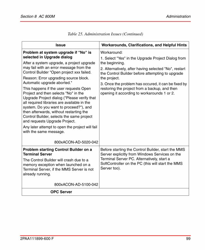
Section 8 AC 800M Administration
2PAA111899-600 F 99
Problem at system upgrade if "No" is selected in Upgrade dialog
After a system upgrade, a project upgrade may fail with an error message from the Control Builder "Open project xxx failed.
Reason: Error upgrading source block. Automatic upgrade aborted."
This happens if the user requests Open Project and then selects "No" in the Upgrade Project dialog ("Please verify that all required libraries are available in the system. Do you want to proceed?"), and then afterwards, without restarting the Control Builder, selects the same project and requests Upgrade Project.
Any later attempt to open the project will fail with the same message.
800xACON-AD-5020-042
Workaround:
1. Select "Yes" in the Upgrade Project Dialog from the beginning.
2. Alternatively, after having selected "No", restart the Control Builder before attempting to upgrade the project.
3. Once the problem has occured, it can be fixed by restoring the project from a backup, and then opening it according to workarounds 1 or 2.
Problem starting Control Builder on a Terminal Server
The Control Builder will crash due to a memory exception when launched on a Terminal Server, if the MMS Server is not already running.
800xACON-AD-5100-042
Before starting the Control Builder, start the MMS Server explicitly from Windows Services on the Terminal Server PC. Alternatively, start a SoftController on the PC (this will start the MMS Server too).
OPC Server
Table 25. Administration Issues (Continued)
Issue Workarounds, Clarifications, and Helpful Hints

Administration Section 8 AC 800M
100 2PAA111899-600 F
AC 800M OPC server got no contact with controllers when Network Switch is restarted
Windows cannot handle more than 64 simultaneous connection requests. If restarting network equipment resulting in more than 21 controllers to reconnect to an already running OPC server this can block the OPC server connections.
800xACON-AD-5100-044
No workaround exist.
Controller
INSUM GroupStart Stop During Switch in Online Upgrade
Group Start objects controlling INSUM objects from ProcessObjInsumLib may stop at an online upgrade. The groupstart objects may stop with the following alarm: Too few available objects.
800xACON-AD-5000-031
Re-synchronize the INSUM GroupStart objects manually after the Online Upgrade.
Advant Fieldbus 100 (AF 100)
Application latency at hot remove of AF100, CI869
IEC 61131-3 task latency might be detected when hot removing CI869 (AF100). A latency of up to 100 ms could be experienced with an AF100 configuration of 200 DSP units.
800xACON-AD-5110-003
Do not configure sort accepted task latency when using AF100.
Table 25. Administration Issues (Continued)
Issue Workarounds, Clarifications, and Helpful Hints

Section 8 AC 800M Administration
2PAA111899-600 F 101
PROFINET IO
AC 800M Webserver for PNIO: 'lifelist' tab is not getting updated
There exist PROFINET communication issues when using Hirschmann switches. When using Hirschmann switches like RS20 or RS30, there might be sporadic communication problems with PROFINET and CI871. The cyclic communication might not start up and/or the life list in the AC 800M web interface will not get updated.
800xACON-AD-5100-034
The problem is caused by the Hirschmann switch that does not operate the PROFINET DCP communication services.
To get it working, start the web based configuration tool of the switch and open the dialog Advanced/Industrial Protocols/PROFINET IO. Activate the PROFINET IO device functionality of the switch by setting Operation to On and confirm with Set. Later, change back this configuration.
Hirschmann switch RS20 as PROFINET IO device might flood the network
The Hirschmann switch shows abnormal behavior if configured as PNIO device below CI871. In case the communication with CI871 was interrupted and gets restarted again the switch starts flooding the network. All CI871 connected to the same Ethernet will lose communication with its devices. A reset of the switch is necessary to resolve the problem.
800xACON-AD-5100-041
The problem occurs only if the interface and port-sub modules of PDev below the DAP are configured. These sub modules have node addresses >=32768. Do not configure these sub modules.
FOUNDATION Fieldbus HSE
Table 25. Administration Issues (Continued)
Issue Workarounds, Clarifications, and Helpful Hints

Administration Section 8 AC 800M
102 2PAA111899-600 F
Hot Remove of a redundant pair of CI860 blocks the controller
If both modules of a redundant pair of CI860 are hot removed simultaneously the controller cyclically makes print outs to the controller log file. This causes an increase of CPU load and blocks the reading of the controller log file. Also the 1131 application is partly disturbed.
800xACON-AD-5100-012
Do not Hot Remove both modules of a redundant pair of CI860 simultaneously. After Hot Removal of one module wait several seconds before doing a Hot Removal of the other module.
If the error occurs, a parallel reset on both controllers in a redundant configuration solves the problem.
Slow reaction time for LD800HSE failover
CI860 is slow at detecting redundancy failover of the LD800HSE, leading to a communication break in Client/Server communication for up to 35 seconds.
800xACON-AD-5100-005
No workaround exists for this issue.
Online Upgrade
Online Upgrade - Not Possible to Acknowledge System Alarms
If there are active system alarms on hardware units during Online Upgrade of controller firmware, these alarms will not be possible to acknowledge after the online upgrade is completed.
800xACON-AD-5100-043
No workaround exists for this issue.
Table 25. Administration Issues (Continued)
Issue Workarounds, Clarifications, and Helpful Hints

Section 8 AC 800M Administration
2PAA111899-600 F 103
High Integrity Controller with CI857 INSUM shut Down during Online Upgrade
A High Integrity controller with CI857 INSUM may shut down itself during online upgrade. The shutdown occurs in upgrade step 7 and when the handover limit set to 1000ms.
800xACON-AD-5110-020
Increase the handover limit when performing an online upgrade of a High Integrity controller with CI857.
Modbus TCP
Modbus TCP Communication through CI867 does not resume through default gateway when next hop gateway is dead
A connection is established between the CI867 as master and external slave on another network. Communication goes through the default gateway as configured. When an ICMP redirect message is received from the default gateway, the CI867 correctly updates the next-hop gateway to the new gateway.
However if the new gateway is dead, then the communication does not resume through the default gateway.
800xACON-AD-5110-016
In order to revert to the default gateway, the CI867 has to be hot swapped or the CI867 configuration has to be downloaded from the control builder to the controller.
Table 25. Administration Issues (Continued)
Issue Workarounds, Clarifications, and Helpful Hints
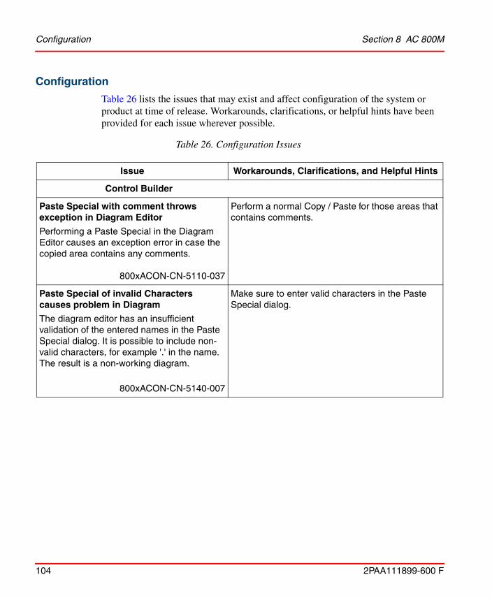
Configuration Section 8 AC 800M
104 2PAA111899-600 F
Configuration
Table 26 lists the issues that may exist and affect configuration of the system or product at time of release. Workarounds, clarifications, or helpful hints have been provided for each issue wherever possible.
Table 26. Configuration Issues
Issue Workarounds, Clarifications, and Helpful Hints
Control Builder
Paste Special with comment throws exception in Diagram Editor
Performing a Paste Special in the Diagram Editor causes an exception error in case the copied area contains any comments.
800xACON-CN-5110-037
Perform a normal Copy / Paste for those areas that contains comments.
Paste Special of invalid Characters causes problem in Diagram
The diagram editor has an insufficient validation of the entered names in the Paste Special dialog. It is possible to include non-valid characters, for example '.' in the name. The result is a non-working diagram.
800xACON-CN-5140-007
Make sure to enter valid characters in the Paste Special dialog.
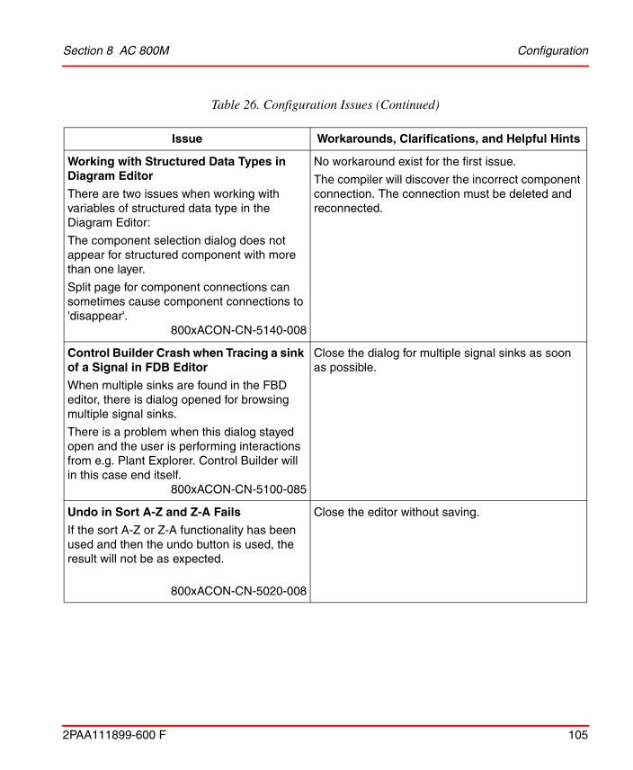
Section 8 AC 800M Configuration
2PAA111899-600 F 105
Working with Structured Data Types in Diagram Editor
There are two issues when working with variables of structured data type in the Diagram Editor:
The component selection dialog does not appear for structured component with more than one layer.
Split page for component connections can sometimes cause component connections to 'disappear'.
800xACON-CN-5140-008
No workaround exist for the first issue.
The compiler will discover the incorrect component connection. The connection must be deleted and reconnected.
Control Builder Crash when Tracing a sink of a Signal in FDB Editor
When multiple sinks are found in the FBD editor, there is dialog opened for browsing multiple signal sinks.
There is a problem when this dialog stayed open and the user is performing interactions from e.g. Plant Explorer. Control Builder will in this case end itself.
800xACON-CN-5100-085
Close the dialog for multiple signal sinks as soon as possible.
Undo in Sort A-Z and Z-A Fails
If the sort A-Z or Z-A functionality has been used and then the undo button is used, the result will not be as expected.
800xACON-CN-5020-008
Close the editor without saving.
Table 26. Configuration Issues (Continued)
Issue Workarounds, Clarifications, and Helpful Hints

Configuration Section 8 AC 800M
106 2PAA111899-600 F
Using Recursive Relations between Objects or Between Libraries Not Allowed
It is not allowed to use recursive relations between objects or between libraries. By using recursive relations between objects or between libraries, Controller may enter "Non responding mode".
For example, if there exists two function block types A and B, you can declare a sub object of type A in type B, but if later on trying to declare a sub object of type B in type A the Control Builder might hang when the editor content is saved.
800xACON-CN-4100-002
If the Control Builder is not responding it has to be killed using Task Manager and then restarted.
Instance Specific Init Values on Embedded Instances
When copying an Instance in Functional Structure and there are embedded instances of object types with Instance Specific Init values set, these Instance Specific Init values are not copied. The Instance Specific values are lost.
800xACON-CN-4100-005
Make sure to check all Instance Specific Init values in the source and make sure these values are set in the copied Instance before the first download.
String Length of 140 Characters Not Supported for String Constants
The maximum length of a string constant is 137 characters even if the length of the string is set to 140 characters.
800xACON-CN-5020-006
No workaround exists for this issue.
Table 26. Configuration Issues (Continued)
Issue Workarounds, Clarifications, and Helpful Hints

Section 8 AC 800M Configuration
2PAA111899-600 F 107
Auto-Reservation Fails for Types Created Using Copy & Paste in Project Explorer
If a Control Module Type or Function Block Type is copied and pasted in the Project Explorer the new type is not auto-reserved.
800xACON-CN-5000-071
The new type needs to be manually reserved by the user.
Using Templates from SeqStartLib Generates the Warning Message: Multiple Calls to Same Function BlockThe Multiple Calls to the Same Function Block compiler switch (introduced in System Version 5.0 SP2) generates warnings for the code that is copied when using the SFC2DSeqChain, for example, from SeqStartLib.
800xACON-CN-5020-010
The warnings can be ignored, or the Multiple Calls to the Same Function Block compiler switch can be set to None.
No User in Online Analysis Dialog
If a download is started very soon after reservations of Applications/Controllers are released from another client, then the information about reservations will be wrong in the Online analysis window which says:
This unit is reserved by”-”
800xACON-CN-5020-007
No workaround exists for this issue.
Table 26. Configuration Issues (Continued)
Issue Workarounds, Clarifications, and Helpful Hints

Configuration Section 8 AC 800M
108 2PAA111899-600 F
Project Documentation from Control Builder
When using the menu entries “Documentation…” and “Documentation Online…” in the Control Builder it is important to not generate too many pages.
The time needed to generate the documentation in word increases dramatically when the number of pages increases. Sometimes it will take long time before the “Cancel” command is accepted by the system; if the document that is to be generated is very large.
800xACON-CN-5000-006
Instead of one big documentation of for example a large library, divide it into several smaller pieces like data types, function blocks and control modules.
Download prohibited if output I/O is disconnected when Copy unconnected outputs is active
If disconnecting an output I/O channel, analog or digital with the option Copy unconnected I/O set to Inputs/Outputs or Outputs, the following warm download will be prohibited with the compile error 9164 - I/O channel was used by another application at last download.
800xACON-CN-5020-024
Disable Copy unconnected outputs in the settings on the controller object and initiate a new download.
Table 26. Configuration Issues (Continued)
Issue Workarounds, Clarifications, and Helpful Hints

Section 8 AC 800M Configuration
2PAA111899-600 F 109
Split and Join blocks not found when doing iterative searches
When using Search and Navigation in Diagrams, connections of variables to Split and Join blocks are not found when doing iterative searches. Iterative searches are the default in online mode but can be turned off by disabling the setting “Iterative searches in Online/Test Mode” found in "Tools->Setup->Station->Search and Navigation Settings". For example, it would be expected to find a reference for a structured variable connected to the out port of a join block, but when using iterative searches this reference is not displayed. If a search is done in offline or without iterative search, the connection will be displayed as a reference as it should.
800xACON-CN-5100-017
No workaround exists for this issue.
Controller
Controller Shutdown during Download after Import of Updated Hardware Library
The AC 800M controller can shut down when doing reconfiguration changes of an updated hardware library. If the channel structure of the hardware library is changed and the Control Builder is not restarted before the reconfiguration, the result could become inconsistent and cause a defensive mechanism in the AC 800M Controller to perform a dual shutdown.
800xACON-CN-5020-093Product Bulletin: 3BSE081800D0002
Always restart Control Builder after importing changes to an already existing hardware library.
When using Environments always make sure the same Hardware Libraries are present in Production and Engineering environments.
When performing an application download after updating an already existing hardware library with changes that affect number or type of I/O connections it can be verified that the changes are applied by checking that both Hardware Library and I/O Connections are marked for change.
Table 26. Configuration Issues (Continued)
Issue Workarounds, Clarifications, and Helpful Hints

Configuration Section 8 AC 800M
110 2PAA111899-600 F
Controller Shutdown during Load Evaluate GO (LEG) Download when 1131 Task without Assignment to Application is present in Controller
The (dual) shutdown will occur if performing the LEG application download when an orphan IEC 1131 task exist in the controller i.e. a 1131 Task that is existing in the controller but the corresponding application is not present in the controller.
800xACON-CN-5100-082Product Bulletin: 3BSE047421D0169
Before performing a LEG download Inspect the IEC 1131 task configuration to ensure that all configured tasks are connected to applications already running in the controller.
SattBus on TCP/IP is not enabled in hardware simulated controller
In a hardware simulated controller the SattBus TCP/IP communication is disabled.
800xACON-CN-5000-081
Make a warm restart (power fail with battery) of the Controller and then the SattBus TCP/IP communication will be enabled.
Communication
IAC stop working when expected SIL configured different for same in variable
When several clients are using the same IAC in variable but with different expected SIL in the same controller, this could cause the previously working clients to receive ISP and error codes from their request.
800xACON-CN-5110-013
There will be an warning message Warning 1616: xxxx Communication variable with Expected SIL Non-SIL not recommended by compiler switch, when performing the reconfiguration.
When setting expected SIL of an IAC in variable, the ongoing communication should not be disturbed.
Table 26. Configuration Issues (Continued)
Issue Workarounds, Clarifications, and Helpful Hints
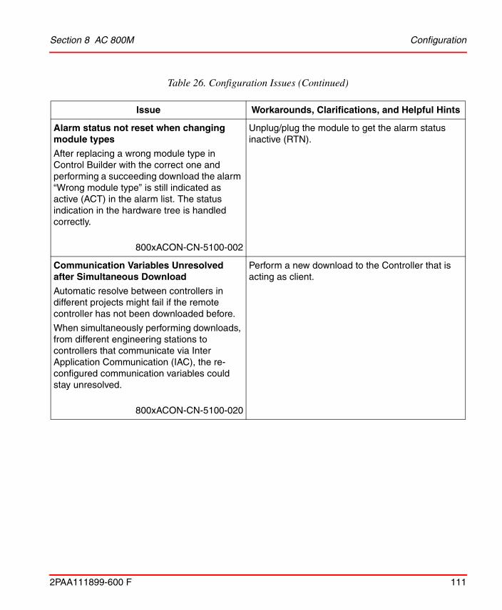
Section 8 AC 800M Configuration
2PAA111899-600 F 111
Alarm status not reset when changing module types
After replacing a wrong module type in Control Builder with the correct one and performing a succeeding download the alarm “Wrong module type” is still indicated as active (ACT) in the alarm list. The status indication in the hardware tree is handled correctly.
800xACON-CN-5100-002
Unplug/plug the module to get the alarm status inactive (RTN).
Communication Variables Unresolved after Simultaneous Download
Automatic resolve between controllers in different projects might fail if the remote controller has not been downloaded before.
When simultaneously performing downloads, from different engineering stations to controllers that communicate via Inter Application Communication (IAC), the re-configured communication variables could stay unresolved.
800xACON-CN-5100-020
Perform a new download to the Controller that is acting as client.
Table 26. Configuration Issues (Continued)
Issue Workarounds, Clarifications, and Helpful Hints
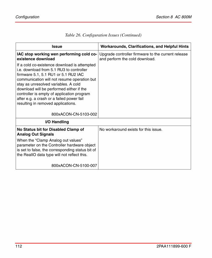
Configuration Section 8 AC 800M
112 2PAA111899-600 F
IAC stop working wen performing cold co-existence download
If a cold co-existence download is attempted i.e. download from 5.1 RU3 to controller firmware 5.1, 5.1 RU1 or 5.1 RU2 IAC communication will not resume operation but stay as unresolved variables. A cold download will be performed either if the controller is empty of application program after e.g. a crash or a failed power fail resulting in removed applications.
800xACON-CN-5103-002
Upgrade controller firmware to the current release and perform the cold download.
I/O Handling
No Status bit for Disabled Clamp of Analog Out Signals
When the “Clamp Analog out values” parameter on the Controller hardware object is set to false, the corresponding status bit of the RealIO data type will not reflect this.
800xACON-CN-5100-007
No workaround exists for this issue.
Table 26. Configuration Issues (Continued)
Issue Workarounds, Clarifications, and Helpful Hints

Section 8 AC 800M Configuration
2PAA111899-600 F 113
Advant Fieldbus 100
Problem with orphans on the AF100 bus
Orphans are CDPs that are not owned by any communication interface. The reason could be that the owning communication interface has been removed or changed station number.
800xACON-CN-5100-010
To avoid orphans on the bus when changing the station number, follow these steps:
1. Move the CI869 for which the station number should be changed to a free position in the hardware tree (in order to preserve its configuration in the control builder). There must not be any CI869 connected to the controller on the position to which the CI869 is moved in the hardware tree.
2. Add a new CI869 with the old station number on the position where the CI869 where moved from in step one.
3. Download and wait until the CI869 is configured.
4. Go offline and delete the CI869 added in step three and move back the CI869 that where moved in step one.
5. Change the station number to the desired number and download.
To avoid orphans when removing a CI869 from the hardware tree configuration follow these steps:
1. Delete all hardware units below the CI869 that are to be removed.
2. Download and wait until the CI869 is configured.
3. Go offline and delete the CI869.
For these steps to have the intended effect, the CI869 must be connected to the bus.
Table 26. Configuration Issues (Continued)
Issue Workarounds, Clarifications, and Helpful Hints
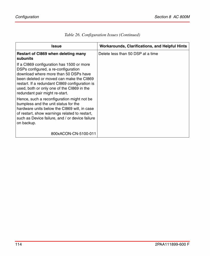
Configuration Section 8 AC 800M
114 2PAA111899-600 F
Restart of CI869 when deleting many subunits
If a CI869 configuration has 1500 or more DSPs configured, a re-configuration download where more than 50 DSPs have been deleted or moved can make the CI869 restart. If a redundant CI869 configuration is used, both or only one of the CI869 in the redundant pair might re-start.
Hence, such a reconfiguration might not be bumpless and the unit status for the hardware units below the CI869 will, in case of restart, show warnings related to restart, such as Device failure, and / or device failure on backup.
800xACON-CN-5100-011
Delete less than 50 DSP at a time
Table 26. Configuration Issues (Continued)
Issue Workarounds, Clarifications, and Helpful Hints

Section 8 AC 800M Configuration
2PAA111899-600 F 115
FOUNDATION Fieldbus HSE
Fraction Cannot be Configured with Fieldbus Builder FF
For analog signals the information min, max, unit and fraction (decimals) can be configured in Fieldbus Builder FF. But only min, max and unit are available after upload in Control Builder. Fraction always gets the default 1.
800xACON-CN-5000-011
A change of the Fraction can be done by setting the value through the application in Control Builder.
FF CS Read block value not updated without error
The Status output parameter of the FF Read/Write Function blocks uses the value 2 to indicate an overrun situation, that is, a new request shall be sent while the response to the previous request has not been received. At the cycle R/W blocks the Warning parameter will additionally be set to true in this situation.
800xACON-CN-5100-014
Typical reasons include insufficient cycle times (internally through cycletime parameter at the cyclic R/W blocks or externally through Req parameter of the non-cyclic R/W blocks) or simultaneous execution of multiple R/W blocks accessing the same CS signal. As a consequence of the overrun situation it cannot be guaranteed that the R/W operation of the affected block has been executed successfully. Furthermore, the block output parameters Valid/Error cannot be relied on for evaluation if a specific operation was successful or not. Therefore the indication of Status 2 requires to increase the cycle time and/or reduce simultaneous use of CS signals to a degree where status 2 is not indicated any longer.
Table 26. Configuration Issues (Continued)
Issue Workarounds, Clarifications, and Helpful Hints

Configuration Section 8 AC 800M
116 2PAA111899-600 F
High Integrity
Corrupt hardware attributes after power fail recovery if preceded by aborted LEG session
The problem described in 800xACON-CN-5100-081 could still occur after a power fail recovery if preceded by the following conditions.
1. LEG is performed with changed I/O connections
2. The LEG session is aborted (not accepted)
3. Power fail occurs before a new LEG or warm re-configuration is performed.
800xACON-CN-5110-047Product Alert 3BSE047421D0179
Ensure that a LEG session that includes changes I/O connections is completed successfully, for more details see the field communication.
Safety Shutdown when Writing to Min and Max Components of I/O Data Types in SIL3 Application
Writing to the Parameter component of a RealIO variable (e.g. Min, Max) connected to an AI880 in a SIL3 application is not permitted and may lead to a safety shutdown of the controller.
Notice that a compiler check for this is missing.
800xACON-CN-5020-092Product Bulletin 3BSE047421D0178
Ensure that channel properties (min/max) for I/O variables is not changed from SIL3 1131 application code. This function will be restricted with a compiler error in future versions of Control Builder.
Table 26. Configuration Issues (Continued)
Issue Workarounds, Clarifications, and Helpful Hints

Section 8 AC 800M Configuration
2PAA111899-600 F 117
Download to Soft HI controller causes compile warning.
When using SoftController HI the following warning will be given “Warning: Firmware for unit PM865 HI/ TP830 at position 0 differs from firmware in connected library”
800xACON-CN-5110-020
The warning is an indication that SoftController version and BasicHIHWLib versions differ but will not inhibit the use of SoftController HI as a debugging and test tool and can be ignored in this situation.
EtherNet/IP and DeviceNet
Device Import wizard does not generate the hardware definition files correctly for eds files of analog devices that support little endian format.
There are some Ethernet IP analog modules with channels of Real data type supporting little endian format. Channels of such devices not work properly after the eds files of such modules are imported using device import wizard.
800xACON-CN-5100-074
No workaround exists for this issue.
Table 26. Configuration Issues (Continued)
Issue Workarounds, Clarifications, and Helpful Hints

Configuration Section 8 AC 800M
118 2PAA111899-600 F
Class1 connection is going to initial state in PLC HW Editor
This problem is observed when a Class 1 tag Read communication is established with the Allen Bradley Logix 5000 series controller. As part of reconfiguration, if the user performs the following, the Class 1 tag variables being already read shall be reset if there are no changes in values for any of the variables.
a. Adds or deletes another connection for the same PLC
b. Moves the position of the PLC instance
800xACON-CN-5110-010
No workaround exists for this issue.
This problem shall not be seen in case the values for the variables being read are changing continuously after a reconfiguration as mentioned in the problem description, is done.
Addition and deletion of the 1734 AENT digital input module
This problem is observed EthernetIP modular IO in case there are some IO modules available under an adaptor in Control Builder and not physically present. As part of the reconfiguration, if the user deletes any such EthernetIP modular IO, the CI873 shall restart and again establish connection with the physically existent IO modules.
In case of redundant CI873, the primary CI873 shall restart and there shall be a failover to backup CI873.
800xACON-CN-5110-011
The workaround for this problem is that the user should always disable connection with the physically non-existent modular IO modules and perform a download. After this the user can delete the IO module and download again.
PROFINET IO
Table 26. Configuration Issues (Continued)
Issue Workarounds, Clarifications, and Helpful Hints

Section 8 AC 800M Configuration
2PAA111899-600 F 119
High memory consumption in Controller when using hardware addresses with high numbers.
When a PROFINET IO device with support of physical device management (PDev) is configured, the memory consumption in the controller increases by 200kb for each device. PDev is supported when high hardware addresses – 32768 to 32770 – are used for the Ethernet adapters below the Device Access Point (DAP) of the device.
800xACON-CN-5100-053
Observe the memory consumption of the controller when adding PROFINET devices below CI871. If the memory has reached a critical level, please contact ABB Technical Support.
I/O connection error with Beckhoff device on PROFINET
A PROFINET device like the BK9053 from Beckhoff does not start up cyclic communication and indicates 'I/O connection error' in the Unit Status of Control Builder. This problem belongs only to devices that provide cyclic data also on sub modules directly configured below the DAP.
800xACON-CN-5100-083
No workaround exist.
IEC 61850
IET600 tool crash for certain CI868 logical nodes
IET600 tool crashes when importing CI868 icd file containing sending Logical Nodes TC1ATCC or TC2ATCC.
800xACON-CN-5110-015
In IET600 tool, import the CI868 icd file that does not contain sending Logical Nodes TC1ATCC or TC2ATCC.
OR
Use CCT600 tool instead of IET600 tool.
Table 26. Configuration Issues (Continued)
Issue Workarounds, Clarifications, and Helpful Hints

Operation Section 8 AC 800M
120 2PAA111899-600 F
Operation
Table 27 lists the issues that may exist and affect operation of the system or product at time of release. Workarounds, clarifications, or helpful hints have been provided for each issue wherever possible.
Table 27. Operational Issues
Issue Workarounds, Clarifications, and Helpful
Hints
Control Builder
Unintentional Stop Order from Process Object at Warm Download
A Process Object set to use pulsed outputs and FBConfig set to 1 has an issue at warm download. An extra stop order is given to an already stopped object. There is no issue in case the object is running. This problem is present in the following objects:
UniCore, BiCore, MotorBiM, MotorValveM, BiM, MotorBi, Bi, MotorValve, BiSimpleM, BiSimple, MotorUniM, ValveUniM, UniM, MotorUni, Uni, ValveUni, UniSimpleM, UniSimple.
800xACON-OL-5000-096
The unintentional stop order should normally not be a problem since the object is already stopped.
SplitRangeCC does not Backtrack Correctly
The SplitRangeCC control module returns an incorrect back value to the preceding modules in case both its outputs are in backtracking mode. The back value will be a copy of the value received from the preceding module. This results in a discontinuous control output once the backtracking ends.
800xACON-OL-5100-120
Avoid connecting the outputs from SplitRangeCC to modules that can be set in manual mode etc.

Section 8 AC 800M Operation
2PAA111899-600 F 121
Resetting Forces in a SIL3 application might shutdown the controller
If I/O forces are reset by application code in SIL3 application with function ResetForcedValue and the diagnostic function block ForcedSignals is executed later in the same application this could result in a controller shut down. The shutdown occur since PM and SM units will have a different perception of the account of actual forced I/O signals for a short time.
800xACON-OL-5020-074
Workaround:
There are different ways to avoid this problem:
• Review the execution order and verify that no call to ResetForcedValue is executed before the ForcedSignals function block.
• If possible Execute ForcedSignals function block in a different applications.
• Remove I/O forces by un-forcing from face plates rather than use application code and don’t allow for force attempts if application is not in a state where they should be accepted.
PID in ERF-mode with Feed Forward does not respond correctly
Using Feed Forward in a PID-object in External Reset Feedback (ERF) mode does not result in the correct output value.
This problem is present in the following objects:
PidCC, PidAdvancedCC.
800xACON-OL-5141-002
Deselect the ERF mode in case Feed Forward is to be used.
Table 27. Operational Issues (Continued)
Issue Workarounds, Clarifications, and Helpful
Hints

Operation Section 8 AC 800M
122 2PAA111899-600 F
Load Evaluate Go:Added I/O Connection not Possible to Force in Control Builder Before Go
If a new I/O connection is added and LEG is downloaded, it is not possible to force this I/O channel from the hardware editor in the Control Builder before Go is performed. (There is no problem with forcing I/O connections that already exist).
Forcing the new I/O connection from Evaluate environment in Process works as it should.
800xACON-OL-5000-042
Force the I/O channel from Process Portal.
Load Evaluate Go: Changed I/O Out Channel Connection may result in Controller Shutdown
If variable connections to Analog Out or Digital Out channels are added, moved, or removed during a LEG session the AC 800M controller may shut down when doing Abort or Accept.
800xACON-OL-5000-095
No workaround exists for this issue.
Table 27. Operational Issues (Continued)
Issue Workarounds, Clarifications, and Helpful
Hints
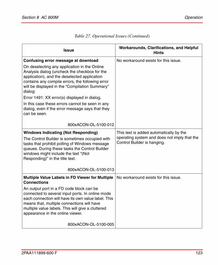
Section 8 AC 800M Operation
2PAA111899-600 F 123
Confusing error message at download
On deselecting any application in the Online Analysis dialog (uncheck the checkbox for the application), and the deselected application contains any compile errors, the following error will be displayed in the “Compilation Summary” dialog:
Error 1491: XX error(s) displayed in dialog.
In this case these errors cannot be seen in any dialog, even if the error message says that they can be seen.
800xACON-OL-5100-012
No workaround exists for this issue.
Windows Indicating (Not Responding)
The Control Builder is sometimes occupied with tasks that prohibit polling of Windows message queues. During these tasks the Control Builder windows might include the text “(Not Responding)” in the title text.
800xACON-OL-5100-013
This text is added automatically by the operating system and does not imply that the Control Builder is hanging.
Multiple Value Labels in FD Viewer for Multiple Connections
An output port in a FD code block can be connected to several input ports. In online mode each connection will have its own value label. This means that, multiple connections will have multiple value labels. This will give a cluttered appearance in the online viewer.
800xACON-OL-5100-005
No workaround exists for this issue.
Table 27. Operational Issues (Continued)
Issue Workarounds, Clarifications, and Helpful
Hints
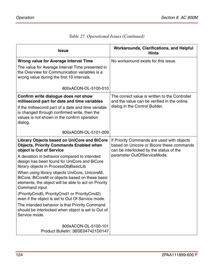
Operation Section 8 AC 800M
124 2PAA111899-600 F
Wrong value for Average Interval Time
The value for Average Interval Time presented in the Overview for Communication variables is a wrong value during the first 10 intervals.
800xACON-OL-5100-010
No workaround exists for this issue.
Confirm write dialogue does not show millisecond part for date and time variables
If the millisecond part of a date and time variable is changed through confirmed write, then the values is not shown in the confirm operation dialog.
800xACON-OL-5101-009
The correct value is written to the Controller and the value can be verified in the online dialog in the Control Builder.
Library Objects based on UniCore and BiCore Objects, Priority Commands Enabled when object is Out of Service
A deviation in behavior compared to intended design has been found for UniCore and BiCore library objects in ProcessObjBasicLib.
When using library objects UniCore, UnicoreM, BiCore, BiCoreM or objects based on these basic elements, the object will be able to act on Priority Command input
(PriorityCmd0, PriorityCmd1 or PriorityCmd2) even if the object is set to Out Of Service mode.
The intended behavior is that Priority Command should be interlocked when object is set to Out of Service mode.
800xACON-OL-5100-101Product Bulletin: 3BSE047421D0147
If Priority Commands are used with objects based on Unicore or Bicore these commands can be interlocked by the status of the parameter OutOfServiceMode.
Table 27. Operational Issues (Continued)
Issue Workarounds, Clarifications, and Helpful
Hints
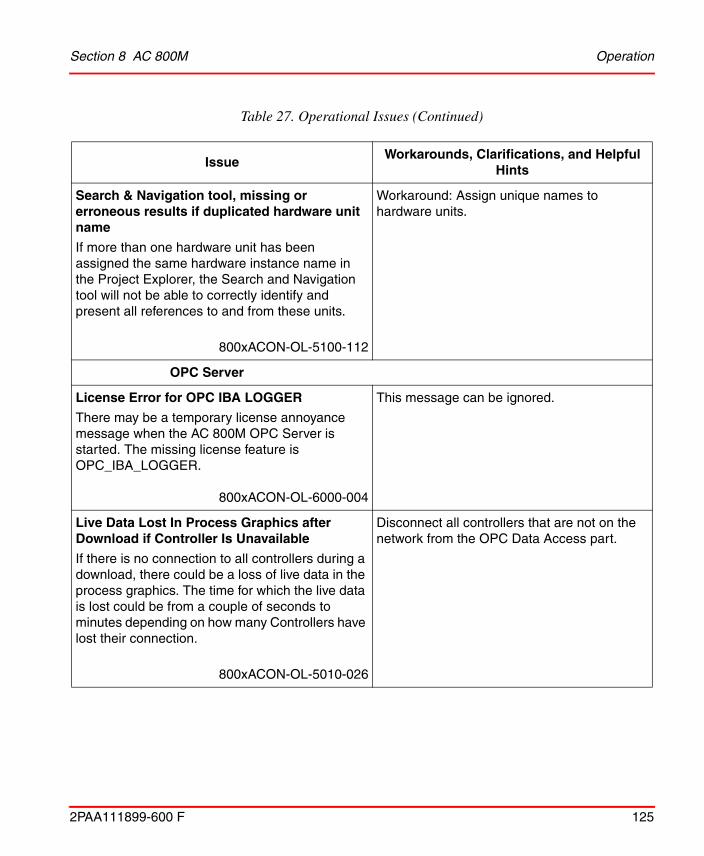
Section 8 AC 800M Operation
2PAA111899-600 F 125
Search & Navigation tool, missing or erroneous results if duplicated hardware unit name
If more than one hardware unit has been assigned the same hardware instance name in the Project Explorer, the Search and Navigation tool will not be able to correctly identify and present all references to and from these units.
800xACON-OL-5100-112
Workaround: Assign unique names to hardware units.
OPC Server
License Error for OPC IBA LOGGER
There may be a temporary license annoyance message when the AC 800M OPC Server is started. The missing license feature is OPC_IBA_LOGGER.
800xACON-OL-6000-004
This message can be ignored.
Live Data Lost In Process Graphics after Download if Controller Is Unavailable
If there is no connection to all controllers during a download, there could be a loss of live data in the process graphics. The time for which the live data is lost could be from a couple of seconds to minutes depending on how many Controllers have lost their connection.
800xACON-OL-5010-026
Disconnect all controllers that are not on the network from the OPC Data Access part.
Table 27. Operational Issues (Continued)
Issue Workarounds, Clarifications, and Helpful
Hints

Operation Section 8 AC 800M
126 2PAA111899-600 F
AC 800M OPC server cannot reestablish connection when lost connection to half an application
If OPC server lost connection to one controller containing a distributed application, then communication could not be reestablished to the other controllers containing the same application after the OPC server was restarted.
800xACON-OL-5100-116
No workaround exist.
800xA for AC 800M
Wrong Status in Alarm List for Redundant Hardware Units
Redundant hardware units report “Redundant mode enabled” instead of “Status OK” in the Alarm List, in Plant Explorer, when the alarm state changes from active to inactive.
800xACON-OL-5000-005
No workaround exists for this issue.
Controller
Low Time Quality for SNTP between Controllers
The time accuracy for clock synchronization using SNTP between controllers may be up to 10ms. The specified accuracy is 1ms.
800xACON-OL-5110-034
No workaround exist. Consider using CNCP instead.
Table 27. Operational Issues (Continued)
Issue Workarounds, Clarifications, and Helpful
Hints
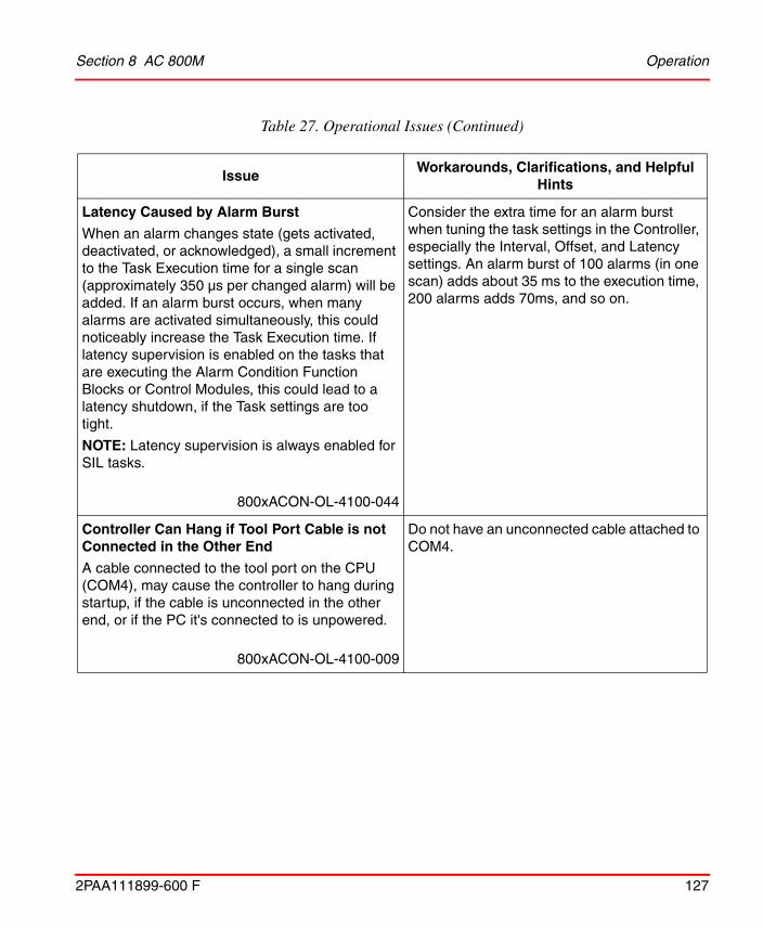
Section 8 AC 800M Operation
2PAA111899-600 F 127
Latency Caused by Alarm Burst
When an alarm changes state (gets activated, deactivated, or acknowledged), a small increment to the Task Execution time for a single scan (approximately 350 µs per changed alarm) will be added. If an alarm burst occurs, when many alarms are activated simultaneously, this could noticeably increase the Task Execution time. If latency supervision is enabled on the tasks that are executing the Alarm Condition Function Blocks or Control Modules, this could lead to a latency shutdown, if the Task settings are too tight.
NOTE: Latency supervision is always enabled for SIL tasks.
800xACON-OL-4100-044
Consider the extra time for an alarm burst when tuning the task settings in the Controller, especially the Interval, Offset, and Latency settings. An alarm burst of 100 alarms (in one scan) adds about 35 ms to the execution time, 200 alarms adds 70ms, and so on.
Controller Can Hang if Tool Port Cable is not Connected in the Other End
A cable connected to the tool port on the CPU (COM4), may cause the controller to hang during startup, if the cable is unconnected in the other end, or if the PC it's connected to is unpowered.
800xACON-OL-4100-009
Do not have an unconnected cable attached to COM4.
Table 27. Operational Issues (Continued)
Issue Workarounds, Clarifications, and Helpful
Hints

Operation Section 8 AC 800M
128 2PAA111899-600 F
Communication
Network Port on Redundant PM891 might Stop Working if Exposed to Excessive ARP Communication
Network ports on a redundant PM891 might stop working if exposed to excessive amount of ARP communication. Address Resolution Protocol (ARP) is a protocol used to resolve network IP-addresses and MAC addresses and is a standard part of TCP/IP communication.
The problem will affect the network port exposed to excessive amount of ARP communication. In a redundant network configuration a failover will occur to the backup network port and the port will be error marked.
The problem can only occur if a CPU failover previously has taken place and then the controller network port is exposed to excessive amount of ARP communication
800xACON-OL-5100-114Product Bulletin: 3BSE047421D0171
To restart a network port that has locked up, perform a CPU failover.
Controller shutdown when using MMS on PPP
The AC 800M controller may shut down if running MMS over PPP on CI853. The problem only occur if both channels on the CI853 is in use.
800xACON-OL-5100-119
If running MMS over PPP on CI853, the other channel on the CI853 must be unused/unconfigured.
Table 27. Operational Issues (Continued)
Issue Workarounds, Clarifications, and Helpful
Hints

Section 8 AC 800M Operation
2PAA111899-600 F 129
S3964ReadCyclic Valid Port toggles during valid Output
The 'Valid' parameter on the S3964Readcyclic Function Block in S3964CommLib is not stable. It toggles true/false even though the data is getting updated.
800xACON-OL-5100-115
Use the Connect block to supervise the communication status.
Safe Peer-to-Peer communication timeout
The default timeout for the MMSRead Control Modules for Safe P2P communication is 2 seconds. This is sufficient to handle a single TCP retransmission, but double TCP retransmissions may occur infrequently, depending on network and controller load. The second retransmission will occur after approximately 4 sec.
800xACON-OL-5020-008
To ensure that double TCP re-transmissions are handled without setting the safe P2P communication invalid, a P2P timeout of at least 5 seconds is required.
Modbus TCP communication throughput with CI867 degrades for cycle times less than 100 ms.
There is a delay in sending packets to slave by the CI867 master when the cycle time for the Read/write requests are less than 100 ms. For cycle times above 100 ms, the packets are send by the CI867 to the slave properly without any delay.
800xACON-OL-5020-069
There is no workaround. For communication without delays, the cycle times for sending Read/Write requests should be more than 100 ms.
Table 27. Operational Issues (Continued)
Issue Workarounds, Clarifications, and Helpful
Hints
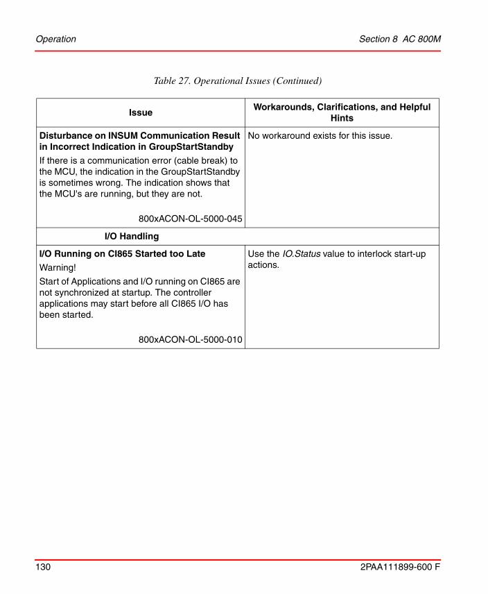
Operation Section 8 AC 800M
130 2PAA111899-600 F
Disturbance on INSUM Communication Result in Incorrect Indication in GroupStartStandby
If there is a communication error (cable break) to the MCU, the indication in the GroupStartStandby is sometimes wrong. The indication shows that the MCU's are running, but they are not.
800xACON-OL-5000-045
No workaround exists for this issue.
I/O Handling
I/O Running on CI865 Started too Late
Warning!
Start of Applications and I/O running on CI865 are not synchronized at startup. The controller applications may start before all CI865 I/O has been started.
800xACON-OL-5000-010
Use the IO.Status value to interlock start-up actions.
Table 27. Operational Issues (Continued)
Issue Workarounds, Clarifications, and Helpful
Hints
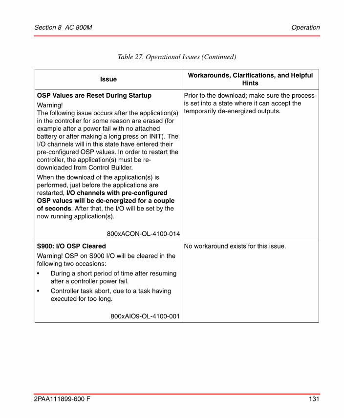
Section 8 AC 800M Operation
2PAA111899-600 F 131
OSP Values are Reset During Startup
Warning!The following issue occurs after the application(s) in the controller for some reason are erased (for example after a power fail with no attached battery or after making a long press on INIT). The I/O channels will in this state have entered their pre-configured OSP values. In order to restart the controller, the application(s) must be re-downloaded from Control Builder.
When the download of the application(s) is performed, just before the applications are restarted, I/O channels with pre-configured OSP values will be de-energized for a couple of seconds. After that, the I/O will be set by the now running application(s).
800xACON-OL-4100-014
Prior to the download; make sure the process is set into a state where it can accept the temporarily de-energized outputs.
S900: I/O OSP Cleared
Warning! OSP on S900 I/O will be cleared in the following two occasions:
• During a short period of time after resuming after a controller power fail.
• Controller task abort, due to a task having executed for too long.
800xAIO9-OL-4100-001
No workaround exists for this issue.
Table 27. Operational Issues (Continued)
Issue Workarounds, Clarifications, and Helpful
Hints

Operation Section 8 AC 800M
132 2PAA111899-600 F
Problems with rmcPTCLib in AC 800M
Hot Swap of CI856 in an AC 800M is not supported if rmcPTCLib is used. In that case a Hot Remove of the CI856 may cause a Controller Crash.
PowerFail restart with CI856 in AC 800M may cause a Controller Crash if rmcPTCLib is used.
800xACON-OL-4104-001
Load the project on a CF card so that the application restarts if there is a controller crash.
FOUNDATION Fieldbus HSE
Pending Error Messages in Hardware Unit Status Are Reset
A CI860 module with the HSE network disconnected indicates 'Channel Error' in the Hardware Unit Status. If the CI860 is reset under this condition, it will restart without showing the error even though the HSE cable may still be disconnected. The same will also happen after a controller cold start.
800xACON-OL-4100-020
Check the status information on the single FF signals to find out about the actual communication status after restart.
Table 27. Operational Issues (Continued)
Issue Workarounds, Clarifications, and Helpful
Hints

Section 8 AC 800M Operation
2PAA111899-600 F 133
Problems with FF Status Value Initialization
The FF status values are not always properly initialized or reset. There are two different actions when these FF status values need to be initialized:
• starting a CI860 module
• removing a channel/signal on one side of a Controller>FF / FF>Controller signal connection
The CI860 I/O-channels are initialized with zeros when a CI860 module starts. This leads to a FF status of 0 on connections, which are used, but not updated. The problem exists in both directions IEC>FF and FF>IEC.
Removing a channel/signal:If the writing side of a Controller>FF signal connection is removed, the last written value, especially the status, is kept. On an FF>Controller signal connection the status is set to 'BAD', if the FF signal is removed, which is ok.
Starting a CI860 module:The current implementation does not ensure, that no longer used values are indicated by a 'BAD' FF status.
800xACON-OL-4100-021
Pay attention to remove variables connected to channels on CI860 that are no longer connected to an FF application, since they are incorrectly indicated as OK.
Table 27. Operational Issues (Continued)
Issue Workarounds, Clarifications, and Helpful
Hints

Operation Section 8 AC 800M
134 2PAA111899-600 F
FFHSE C/S Read and Write request gets status error (2) first and then status OK
FFHSERead and FFHSEWrite function blocks might temporarily indicate error status 2 which means warning. But the requests are operated successfully and status gets OK finally.
800xACON-OL-5101-010
Wait for some time after sending the request, before operating the error status.
CI860: Client/server connection breaks after change of IP address
When changing the IP-addresses of a redundant pair of CI860 the active Client/Server communication via FFHSERead and FFHSEWrite is stopped. The cyclic Publish / Subscribe communication is not affected. Changing the IP-address of a non-redundant CI860 is working with C/S as supposed.
800xACON-OL-5101-011
Perform HotSwap of primary CI860 to restart the Client/Server communication.
MOD 5
Internal FW error in CI872 at application download
Internal FW error in CI872 at application download and CI872 modules are not up. The message "Internal HW Error (see CI Log)" alarm is shown, and both CI872 modules in case of redundancy or single CI872 module in case of non-redundancy are not up.
800xACON-OL-5100-066
Workaround for this scenario, where no CI872 module is up, is to manually hot swap the CI872 modules.
Table 27. Operational Issues (Continued)
Issue Workarounds, Clarifications, and Helpful
Hints

Section 8 AC 800M Operation
2PAA111899-600 F 135
Switchover occurs despite CPUID conflict in backup CI872
Failover from primary CI872 module to the backup CI872 module occurs, even though CPUID conflict exists in the backup CI872 module.
800xACON-OL-5023-006
In a redundant configuration of CI872 modules, always ensure that the backup CI872 is correctly configured, by checking its unit status in the Hardware Tree.
MTMConnect FB doesn't show '-7006' while FOC is disconnected
The MTMConnect function block does not update the status of the physical connection when MTMReadCyc or MTMDefCyc function blocks are not connected to that MTMConnect.
800xACON-OL-5023-008
This occurs when MTMConnect is not connected to MTMReadCyc or MTMDefCyc function blocks of MTMCommLib. If any error in the physical connection occurs, the status code -7006 (for any error in physical connection) is not displayed for MTMConnect.
To get an update of the status of the physical connection through an MTMConnect function block in an application, either connect an MTMReadCyc function block to the MTMConnect and enable this MTMReadCyc, or connect an MTMDefCyc function block to the MTMConnect.
IEC 61850
Table 27. Operational Issues (Continued)
Issue Workarounds, Clarifications, and Helpful
Hints

Operation Section 8 AC 800M
136 2PAA111899-600 F
CI868 Module restart during Co-existance Download and SCD-File Reconfiguration
CI868 Module shall restart leading to disturbance in connected IEC61850 Network in the following scenarios:
• Downloading application after upgrading to new Control Builder M with newer CI868HwLib in Connected Library. CI868 shall not restart during subsequent downloads from Upgraded Control Builder M project.
• Downloading application after importing Reconfigured Scd-file. This is applicable for each download with re-configured scd-file.
800xACON-OL-6000-001
No workaround exists for this issue.
CI868 does not support receiving same signal from GCB as well as RCB
Configuring same LN signals in GCB as well as RCB datasets leads to communication error in CI868 module.
800xACON-OL-6000-002
No workaround exists for this issue
Table 27. Operational Issues (Continued)
Issue Workarounds, Clarifications, and Helpful
Hints

Section 8 AC 800M Operation
2PAA111899-600 F 137
TCP Communication Library
User defined UDPProtocol allow broadcast set to false has no effect
Even though the parameter AllowBroadcasts is set to False, it is still possible to send (and receive) broadcast messages.
800xACON-OL-5110-008
No workaround exists for this issue.
High Integrity
Safe Online Write - Error Handling
When performing a Safe Online Write operation and the Confirm Write Support aspect is missing, the standard (non-SIL) confirm dialog implemented in PPA shows up instead of an error message telling that the confirm write support is missing.
It is possible to confirm the write operation but it will not be recognized as a SOW operation neither by the OPC server nor the HI controller, hence the write operation will never be accepted by the HI controller.
800xACON-OL-6000-003
No workaround exists for this issue.
Table 27. Operational Issues (Continued)
Issue Workarounds, Clarifications, and Helpful
Hints

Operation Section 8 AC 800M
138 2PAA111899-600 F
Discrepancy in application if all MMS communication was disabled.
A MMS discrepancy in SIL3 application could occur if all MMSReadXX control modules, connected to the same Partner, was disabled at the same time and then later enabled. This could lead to a controller shutdown if MMS input data was used in critical loop.
For SIL2 applications there will not be any faulty data. The effect of this problem will be that the MMS data will be marked as Valid one scan before the fault counter is fully incremented, but only if data is correct.
800xACON-OL-5020-075
No workaround exists for this problem.
Table 27. Operational Issues (Continued)
Issue Workarounds, Clarifications, and Helpful
Hints

Section 8 AC 800M Preparations Before an Online Upgrade of an AC 800M using CI857
2PAA111899-600 F 139
Preparations Before an Online Upgrade of an AC 800M using CI857
Use the INSUM MMI or the INSUM OS to set the parameter “FailSafe Heartbeat” on the INSUM TCP/IP Gateway to a value which is 1/4 of the shortest “Failsafe TimeOut” on the connected INSUM devices (MCUs, Circuit Breakers).
In normal operation CI857 sends FailSafe heartbeat messages to the INSUM subnets according to the parameters on the INSUMGateway hardware unit.
During the online upgrade, CI857 disconnects from the INSUM system for some time and since there is no redundancy for CI857 no commands can be sent to the INSUM system and the measurement values are not updated during this time.
After the online upgrade CI857 reconnects to the INSUM system and the communication is reestablished.
The time the connection is broken between CI857 and the INSUM system is different depending on if the firmware of CI857 is upgraded or not.
If the firmware of CI857 is upgraded, it is done in step 8 of the online upgrade together with “the remaining units”.
Before CI857 disconnects from the INSUM system it requests the INSUM TCP/IP Gateway to send Failsafe Heartbeat to all INSUM subnets so that this continues until the CI857 reconnects.
If CI857 for some reason does not reconnect within the expected time the INSUM TCP/IP Gateway stops sending Failsafe Heartbeat to the INSUM devices (MCUs and Circuit Breakers) and they will go to Failsafe. The timeout used by the INSUM TCP/IP gateway is set by the AC 800M depending on the expected time until it can reconnect. This is described below.
If the firmware of CI857 is not upgraded the communication between CI857 and the INSUM system is broken for some seconds during step 7 of the online upgrade. This is the case if the firmware is up-to-date already before the online upgrade of the controller and an upgrade of CI857 is indicated as “Not Available” in step 2 of the online upgrade. This is also the case if an upgrade of CI857 is indicated as “Recommended” in step 2 of the online upgrade, but the user decides not to upgrade. If the CI857 does not reconnect within 15 seconds after the switch in step 7 the INSUM devices will go to failsafe.
Preparations Before an Online Upgrade of an AC 800M using CI857 Section 8 AC 800M
140 2PAA111899-600 F
If an upgrade of CI857 is indicated as “Recommended” and the user decides to do the upgrade the communication between CI857 and the INSUM system is broken two times. First for some seconds during step 7 and then later for a longer time during step 8 while the firmware is downloaded. Between these communication breaks the communication is executed as normal. If the CI857 does not reconnect within 300 seconds after the start of the firmware download the INSUM devices will go to failsafe.
If an upgrade of CI857 is indicated as “Mandatory” the communication CI857 and the INSUM system is broken at the switch in step 7 and not reestablished until after the upgrade of the firmware of CI857. If the CI857 does not reconnect within 900 seconds after the switch the INSUM devices will go to failsafe.
In this upgrade case it is important to notice that the time the communication is broken depends on how long time the user waits in step 8 in the online upgrade wizard.
During the switch in step 7 the Status of the INSUMReceive and INSUMWrite blocks may be -5324 or -15 for up to 8 seconds. The user needs to take this into account in the application. ProcessObjInsumLib takes care of this internally.
If an upgrade has been started and the communication between the CI857 and the INSUM TCP/IP Gateway is interrupted during step 3, where Redundancy is turned off, the upgrade will be terminated.
The upgrade is possible to perform if the communication between the CI857 and the INSUM TCP/IP Gateway is disconnected during the entire upgrade session.

2PAA111899-600 F 141
Section 9 Application Change Management
Known ProblemsThis section lists the Known Problems of Application Change Management (ACM) that exist in the system at the time of release.
Operation
Table 28 lists the operational issues that may exist and affect the system or product at time of release. Workarounds, clarifications, or helpful hints have been provided for each issue wherever possible.
Table 28. Operational Issues
Issue Workarounds, Clarifications, and Helpful Hints
In ACM client, Delete at Import functionality is not functional.
800xAACM-OL-5140-005
No workaround exists for this issue.
Loading the System extension, 'ACM for Engineering Studio' fails due to missing dependent extension.
800xAACM-OL-6000-003
Load system Extension, 'Engineering Base' before loading 'ACM for Engineering Studio'.

Operation Section 9 Application Change Management
142 2PAA111899-600 F
If subsequent check in is performed on an object/entity after modifications with respect to earlier checked in version. Check in comment gets modified for all its dependent objects/entity, even if there are no changes in those objects.
800xAACM-OL-6000-002
No workaround exists for this issue.
In few instances, check-in of objects/entities with more than 100 child objects may take significant amount of time.
800xAACM-OL-6000-001
Planning is required before performing the operation.
Table 28. Operational Issues (Continued)
Issue Workarounds, Clarifications, and Helpful Hints
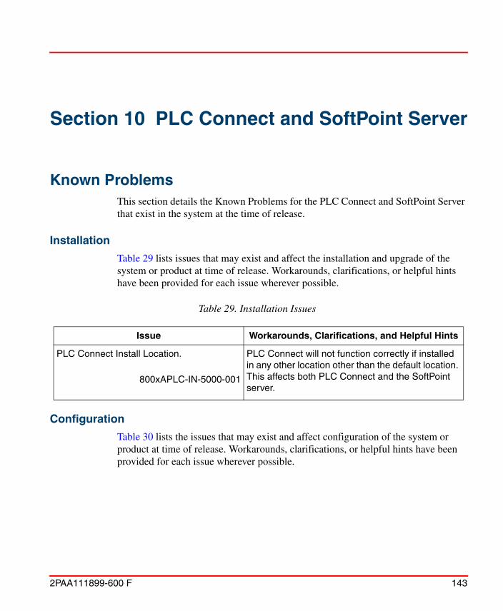
2PAA111899-600 F 143
Section 10 PLC Connect and SoftPoint Server
Known ProblemsThis section details the Known Problems for the PLC Connect and SoftPoint Server that exist in the system at the time of release.
Installation
Table 29 lists issues that may exist and affect the installation and upgrade of the system or product at time of release. Workarounds, clarifications, or helpful hints have been provided for each issue wherever possible.
Configuration
Table 30 lists the issues that may exist and affect configuration of the system or product at time of release. Workarounds, clarifications, or helpful hints have been provided for each issue wherever possible.
Table 29. Installation Issues
Issue Workarounds, Clarifications, and Helpful Hints
PLC Connect Install Location.
800xAPLC-IN-5000-001
PLC Connect will not function correctly if installed in any other location other than the default location. This affects both PLC Connect and the SoftPoint server.
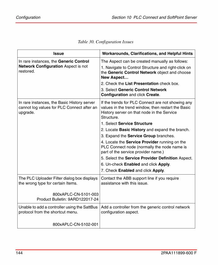
Configuration Section 10 PLC Connect and SoftPoint Server
144 2PAA111899-600 F
Table 30. Configuration Issues
Issue Workarounds, Clarifications, and Helpful Hints
In rare instances, the Generic Control Network Configuration Aspect is not restored.
The Aspect can be created manually as follows:
1. Navigate to Control Structure and right-click on the Generic Control Network object and choose New Aspect…
2. Check the List Presentation check box.
3. Select Generic Control Network Configuration and click Create.
In rare instances, the Basic History server cannot log values for PLC Connect after an upgrade.
If the trends for PLC Connect are not showing any values in the trend window, then restart the Basic History server on that node in the Service Structure.
1. Select Service Structure
2. Locate Basic History and expand the branch.
3. Expand the Service Group branches.
4. Locate the Service Provider running on the PLC Connect node (normally the node name is part of the service provider name.)
5. Select the Service Provider Definition Aspect.
6. Un-check Enabled and click Apply.
7. Check Enabled and click Apply.
The PLC Uploader Filter dialog box displays the wrong type for certain Items.
800xAPLC-CN-5101-003Product Bulletin: 9ARD122017-24
Contact the ABB support line if you require assistance with this issue.
Unable to add a controller using the SattBus protocol from the shortcut menu.
800xAPLC-CN-5102-001
Add a controller from the generic control network configuration aspect.

Section 10 PLC Connect and SoftPoint Server Operation
2PAA111899-600 F 145
Operation
Table 31 lists the issues that may exist and affect operation of the system or product at time of release. Workarounds, clarifications, or helpful hints have been provided for each issue wherever possible.
Upgrade from 4.1 or older to 5.0 does not work correctly.
800xAPLC-CN-5010-007
The old Alarm Control Aspect cannot be deployed in System Version 5.0. Therefore this must be changed to the new Alarm Control Aspect made for System Version 5.0.
After executing the above specified changes, PLC Connect Service group for the Event collector must be changed.
In the aspect Service Group Definition, change Collecting Mapping to "Ads OPC Event Server". Also the Event/Alarm list must be reconfigured. Do not use lists with 4.1 in front of name.
Ensure to use Display Tool after these changes.
It is likely to affect SoftPoint server.
Not possible to change the SB-channel.
800xAPLC-CN-5011-004
After deploy the CommServer is owner of the SB-driver and therefore it is not possible to change the SB-channel.
Stop the CommServer.It is not likely to affect SoftPoint server.
Minimum size of Modbus telegrams too large in PLC Connect.
800xAPLC-CN-5020-011
The Modbus driver does not support telegrams smaller than 32 Coils and 16 registers. This does not affect the SoftPoint server.
Table 30. Configuration Issues (Continued)
Issue Workarounds, Clarifications, and Helpful Hints
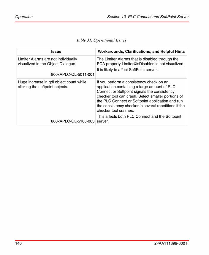
Operation Section 10 PLC Connect and SoftPoint Server
146 2PAA111899-600 F
Table 31. Operational Issues
Issue Workarounds, Clarifications, and Helpful Hints
Limiter Alarms are not individually visualized in the Object Dialogue.
800xAPLC-OL-5011-001
The Limiter Alarms that is disabled through the PCA property LimiterXisDisabled is not visualized.
It is likely to affect SoftPoint server.
Huge increase in gdi object count while clicking the softpoint objects.
800xAPLC-OL-5100-003
If you perform a consistency check on an application containing a large amount of PLC Connect or Softpoint signals the consistency checker tool can crash. Select smaller portions of the PLC Connect or Softpoint application and run the consistency checker in several repetitions if the checker tool crashes.
This affects both PLC Connect and the Softpoint server.

2PAA111899-600 F 147
Section 11 SFC Viewer
Known ProblemsThis section details the Known Problems for SFC Viewer that exist in the system at the time of release.
Operation
Table 32 lists the issues that may exist and affect operation of the system or product at time of release. Workarounds, clarifications, or helpful hints have been provided for each issue wherever possible.
Table 32. Operational Issues
Issue Workarounds, Clarifications, and Helpful Hints
If a parameter with direction in, used in a sequence, is modified after obtaining the driving object path, further upload (through SFC Uploader aspect) does not update this modified signal.
800xASFC-OL-5110-005
No workaround exists for this issue.

Operation Section 11 SFC Viewer
148 2PAA111899-600 F
If an output reference variable, introduced in a step, is used as input reference in transitions in the same sequence or a different sequence, the action window corresponding to this step displays multiple tags with the same output reference variable name.
800xASFC-OL-5110-006
No workaround exists for this issue.
The object navigation feature from the tag displayed in the List View of transition window is not supported if the description of the tag contains an “_” (underscore) character.
800xASFC-OL-5110-007
No workaround exists for this issue.
If the project constant used in transition is of non-Boolean type, clicking Unfulfilled Criteria (in online mode) in the transition window results in display of two entries of this project constant.
800xASFC-OL-5110-010
No workaround exists for this issue.
Table 32. Operational Issues (Continued)
Issue Workarounds, Clarifications, and Helpful Hints

Section 11 SFC Viewer Operation
2PAA111899-600 F 149
Sequence selection branch has the following issues:
• A transition, connected to a jump in different vertical position, misses the connection to the step.
• Jump from the step is overlapping with closing selection line.
• Jump to the step is overlapping with closing selection line.
800xA-MEL-OL-5102-004
No workaround exist for these issues.
SFC Viewer has the following display issues:
• When there is no direct connection from a transition to a step, and a jump is available above the same step, a vertical line which is not required is drawn above it.
• The closing line of the simultaneous branch is missing when the branch is configured from the first X position.
800xA-MEL-OL-5102-005
No workaround exist for these issues.
Object navigation in a transition may not work if the name of a variable in Engineering Workplace is different from Control Builder M. By default, Control Builder M name is considered.
800xASFC-OL-5130-012
No workaround exists for this issue.
Table 32. Operational Issues (Continued)
Issue Workarounds, Clarifications, and Helpful Hints

Operation Section 11 SFC Viewer
150 2PAA111899-600 F
Transition view of SFC Viewer sometimes does not show the complete path of a variable transition, resulting in difficulty to identify the actual variable that is referred.
800xASFC-OL-5130-017
No workaround exists for this issue.
The transition view of the SFC Viewer does not differentiate between the tag name and the variable name displayed in the list.
800xASFC-OL-5140-001
No workaround exists for this issue.
While working with Multisystem Integration SFC Viewer status except the active step is not synchronized between provider and subscriber.
800xASFC-OL-6000-001
No workaround exists for this issue.
In some instance when workplace log over is enabled, performing SFC uploader ends up in error.
800xASFC-OL-6000-002
Before performing SFC uploader please follow the steps mentioned below.
1. Log in as 800xA user having Local Admin rights on that node.
2.Open Control Builder with elevated privileges (Right Click on the tool and select "Run as Administrator" from the context menu)
3.Open the respective project.
4. Then Press Upload.
Table 32. Operational Issues (Continued)
Issue Workarounds, Clarifications, and Helpful Hints

2PAA111899-600 F 151
Section 12 Process Engineering ToolIntegration
Known ProblemsThis section details the Known Problems for Process Engineering Tool Integration that exist in the system at the time of release. It also enumerates known problems encountered in the final testing of this product release and identifies workarounds that help overcome the problem.
Installation
Table 33 lists issues that may exist and affect the installation and upgrade of the system or product at time of release. Workarounds, clarifications, or helpful hints have been provided for each issue wherever possible.
Table 33. Installation Issues
Issue Workarounds, Clarifications, and Helpful Hints
In rare cases, PETI cannot be launched from the ABB Start Menu. This is because the required files may not be copied to the local disk during installation.
800xAENP-IN-6000-001
Uninstall and re-install PETI.

Operation Section 12 Process Engineering Tool Integration
152 2PAA111899-600 F
Operation
Table 34 lists the issues that may exist and affect operational of the system or product at time of release. Workarounds, clarifications, or helpful hints have been provided for each issue wherever possible.
Table 34. Operational Issues
Issue Workarounds, Clarifications, and Helpful Hints
After a PETI transfer to 800xA, all Applications in a Control Project are connected to all Controllers in the Control Project instead of specific connections.
800xAENP-OL-5110-011
No workaround exists for this issue.
Move/Delete Objects tab for Object Reconciliation functionality under Object Reconciliation Utility does not work.
800xAENP-OL-5110-005
No workaround exists for this issue.
Trying to save all missing objects using Tools option in PETI results in an error message stating “Compare aborted, Object not set to an instance of an object”.
800xAENP-OL-5110-006
No workaround exists for this issue.
Using PETI, while transferring data to 800xA Process Portal A, some objects are not created, but in Transfer window Object was created is displayed. However the objects are not created in Process Portal A/Control Builder.
800xAENP-OL-5110-002
No workaround exists for this issue.

Section 12 Process Engineering Tool Integration Operation
2PAA111899-600 F 153
If PETI is used to create the Function Diagram with the objects and CreatedByPETI aspect is not added, then new child objects are added to the diagram instead of modifying or renaming the original child objects.
800xAENP-OL-5110-003
No workaround exists for this issue.
Function Diagram cannot be allocated to specified control application, on mapping CBApplication and CBController properties of Allocatable Group aspect of the Function Diagram.
800xAENP-OL-5110-004
No workaround exists for this issue.
An exception message appears if Process Engineering Tool Integration is asked to perform a transformation without selecting any transformation.
800xAENP-OL-5100-009
Select at least one transformation before performing Transformer in Process Engineering Tool Integration.
Also, when an exception occurs, click Continue to ignore the exception and then click Back to exit the Transformer and proceed.
System stops with System out of memory error message, whenever loading a huge (more than 60 MB) CAEX file for the second time.
800xAENP-OL-5100-010
Close the application. Reopen it and reload the file.
Unhandled exception error is displayed, if the CAEX Editor is closed using the X (close) button placed in the top right corner of the window.
800xAENP-OL-5100-011
Always use the Cancel button to close the CAEX Editor.
Table 34. Operational Issues (Continued)
Issue Workarounds, Clarifications, and Helpful Hints

Section 12 Process Engineering Tool Integration
154 2PAA111899-600 F
Objects created by PETI in Control Structure under Control Network like Controller, IO modules on 800xA side, that are available in the INTools/SPI data source, are not detected as existing objects after running a data compare. They are highlighted in Green indicating as new objects.
800xAENP-OL-5140-001
No workaround exists for this issue.
Table 34. Operational Issues (Continued)
Issue Workarounds, Clarifications, and Helpful Hints

2PAA111899-600 F 155
Section 13 IEC 61850
Known ProblemsThis section details the Known Problems for the IEC 61850 that exist in the system at the time of release.
Configuration
Table 35 lists the issues that may exist and affect configuration of the system or product at time of release. Workarounds, clarifications, or helpful hints have been provided for each issue wherever possible.
Table 35. Configuration Issues
Issue Workarounds, Clarifications, and Helpful Hints
CET IEC61850 OPC Server Not Responding
CET IEC61850 OPC Server tool goes to Not Responding State occasionally for Projects with maximum Configuration (4 OPC Instances x 80 IEDs per Instance).
800xAIEC-CN-6000-021
None.
The CET IEC61850 OPC Server tool does not crash, but comes out from Not Responding to a Normal State within short time.
To overcome this, split the maximum CET Project configuration into multiple CET projects, each with only 1 or 2 OPC instances.

Configuration Section 13 IEC 61850
156 2PAA111899-600 F
PPA generates unwanted discarded alarms for each data object when initially connected to IEC61850 OPC Server.
CET generates Inactive alarms for unconfigured Data Objects mapped with default indication events.
These inactive Alarms causes the PPA to discard them as there were no corresponding Active alarms generated in the first place.
800xAIEC-CN-6000-022
Remove pre-configured Indication events for unused Data Objects.
OR
Complete the Alarm & Event configuration for All data objects in CET Project by providing the limit properties before performing the first Update & Reload Action.
Sometimes, launching CET by double- clicking CET icon leads to PCMFrame error.
800xAIEC-CN-6000-023
Right-click on CET Icon and from the context Menu select 'Run As Administrator'.
IEC 61850 Uploader hangs while uploading scd-file having multiple subnetworks successively.
800xAIEC-CN-5140-002
After uploading one subnetwork, close and reopen the Plant Explorer Workplace and then select the IEC 61850 Uploader Aspect to continue with other Subnetwork.
Repeat this step until all the Subnetworks are uploaded.
IEC 61850 CET OPC Server does not generate condition events for Analog Measurement Monitoring of High and Low Levels.
Hence High and Low Level Alarms are Not available in 800xA Alarm List.
800xAIEC-CN-5140-005
Analog Measurement Monitoring of High and Low Levels are available in 800xA Event List.
Table 35. Configuration Issues (Continued)
Issue Workarounds, Clarifications, and Helpful Hints

Section 13 IEC 61850 Configuration
2PAA111899-600 F 157
PPA Event collector service provider is not able to resolve progID correctly.
IEC61850 Event category inflation floods OperateITData folder and slows down system.
Alarm categories selection in Alarm and Event list Configuration Aspect is found different in Primary Aspect Server and Secondary Aspect Server.
800xAIEC-CN-5023-011
Check the Alarm Collection Definition in Library Structure. Check the following in Alarm & Event > alarm collection Definitions > IEC 61850 OPC AE Server > Alarm Collection Definition:
Under IEC61850 OPC AE Instance[x] (where x between 1 -16), Category Group must be “Un-Categorized” and Category Name must be “Condition Discrete Event IEC61850 OPC AE Server Instance[x]” (where x between 1 -16, x should match the instance number).
Otherwise, in the Alarm Collection Definition, delete the IEC61850 OPC AE Instance[x] that has incorrect Category Group and Category Name.
Go to Service Structure, delete the respective Event Collector Service Group and Service Provider and recreate them.
In Plant Explorer Event Collector, while configuring for the first time, select ABB OPC Server for 800xA instead of OPC server instance from Description of AE Server drop-down list. Click Apply and then check if the correct OPC server ProgID is displayed in the ProgID field (ProgID field should NOT be ABB.OPCEventServer.1 but reflect OPC server instance).
If not, select ABB OPC AE Server for 800xA again and apply configuration. Click Apply and again check if the correct OPC server ProgID is displayed in the ProgID field.
Table 35. Configuration Issues (Continued)
Issue Workarounds, Clarifications, and Helpful Hints

Configuration Section 13 IEC 61850
158 2PAA111899-600 F
IEC 61850 CET OPC Server displays an error “Project conversion tool can't access the project: Object reference not set to an instance of an Object” while opening a project exported from earlier CET version.
This is observed on rare occasions due to inconsistency in exported project
800xAIEC-CN-5021-001
1. Create a new project in CET and add 'Computer Node' and 'OPC Server' objects.
2. Perform SCL Import operation on OPC Server object, providing the project xml file located in C:\ PCMDataBases\ OPC_61850\ OPCSCLExport\ <CET_Proj>\xxxx.xml
3. After SCL Import is complete, enter the prog IDs for OPC DA and AE instances in OPC server Object properties and perform Update/Reload.
NOTE: For the second OPC server instance applicable in same CET project, respective xml files will be available in the above path that can be imported additionally.
Sometimes CET Tool throws Server Execution Failed error while performing IEC61850 OPC Server Reload operation.
Thereby it is not able to load the IEC61850 OPC Server with new CET configuration.
800xAIEC-CN-5140-019
This issue is suspected to occur when the OPC Restart time exceeds the DCOM Transaction timeout after which CET throws the error message.
Reason might be due to size of the configuration or overall performance of the Node.
Follow the 800xA recommended Server hardware to avoid the occurrence of issue.
Table 35. Configuration Issues (Continued)
Issue Workarounds, Clarifications, and Helpful Hints
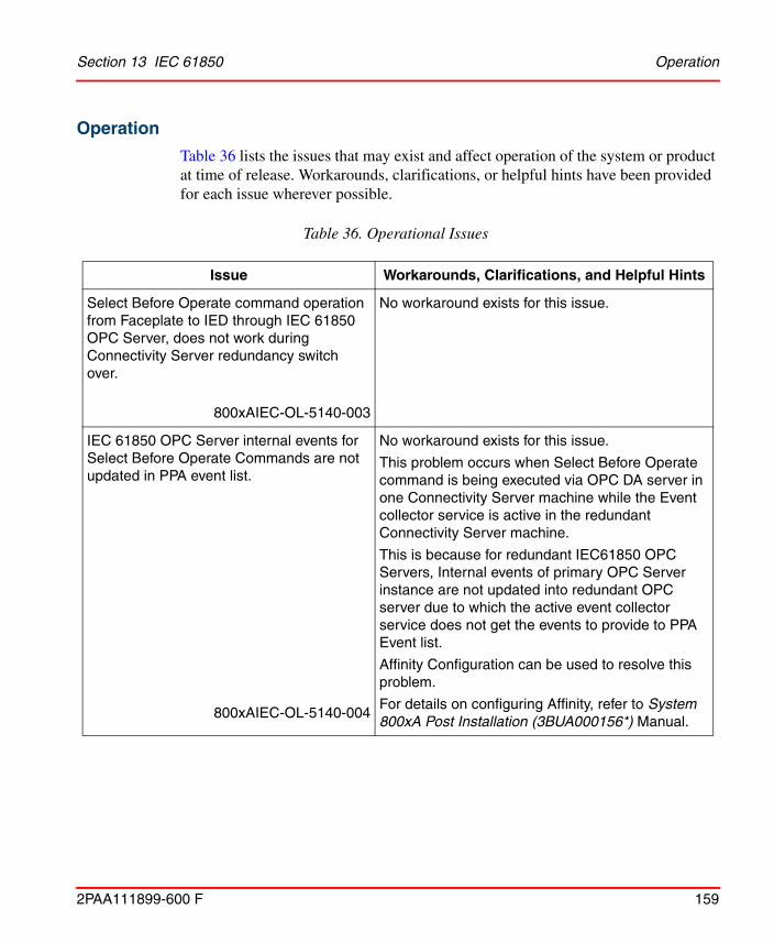
Section 13 IEC 61850 Operation
2PAA111899-600 F 159
Operation
Table 36 lists the issues that may exist and affect operation of the system or product at time of release. Workarounds, clarifications, or helpful hints have been provided for each issue wherever possible.
Table 36. Operational Issues
Issue Workarounds, Clarifications, and Helpful Hints
Select Before Operate command operation from Faceplate to IED through IEC 61850 OPC Server, does not work during Connectivity Server redundancy switch over.
800xAIEC-OL-5140-003
No workaround exists for this issue.
IEC 61850 OPC Server internal events for Select Before Operate Commands are not updated in PPA event list.
800xAIEC-OL-5140-004
No workaround exists for this issue.
This problem occurs when Select Before Operate command is being executed via OPC DA server in one Connectivity Server machine while the Event collector service is active in the redundant Connectivity Server machine.
This is because for redundant IEC61850 OPC Servers, Internal events of primary OPC Server instance are not updated into redundant OPC server due to which the active event collector service does not get the events to provide to PPA Event list.
Affinity Configuration can be used to resolve this problem.
For details on configuring Affinity, refer to System 800xA Post Installation (3BUA000156*) Manual.

Miscellaneous Section 13 IEC 61850
160 2PAA111899-600 F
Miscellaneous
Table 37 list the problems or issues known to exist with the current release that do not fit into one of the other categories. Workarounds, clarifications, or helpful hints have been provided for each issue wherever possible.
During redundancy switchover, if operator sends the command to IED, command will not go to the field devices such as IED,CBR,GEN,PTR and it will not send any feedback to operator workplace. Also, a data loss is observed in control connection, trend etc., during redundancy switchover.
800xAIEC-OL-5020-0001
When the redundancy switchover is going on, the graphic display will show red cross mark (Uncertain or Bad status). Wait until the red cross mark disappears and the graphic display becomes normal.
Table 37. Miscellaneous Issues
Issue Workarounds, Clarifications, and Helpful Hints
Consistency check on functional structure throws error. Running Consistency check tool on functional structure throws error “Could not find data source structure key” for substation level, Bay level and voltage level objects.
800xAIEC-MS-5100-001
Data source is not mapped for objects substation, Bay and voltage as they are not added into control structure while upload. Errors on those objects to be ignored as no undesirable impact on backup or restore.
Table 36. Operational Issues (Continued)
Issue Workarounds, Clarifications, and Helpful Hints

2PAA111899-600 F 161
Section 14 Device Management FOUNDATIONFieldbus
Known ProblemsThis section details the Known Problems for the Device Management FOUNDATION Fieldbus that exist in the system at the time of release.
Installation
Table 38 lists issues that may exist and affect the installation and upgrade of the system or product at time of release. Workarounds, clarifications, or helpful hints have been provided for each issue wherever possible.
Table 38. Installation Issues
Issue Workarounds, Clarifications, and Helpful Hints
Upgrade fails for systems having only PG2 graphics
If Foundation FIELDBUS is used in a 5.1 system (all versions) and if Visual Basic Graphics or Faceplates are not used, the system may contain Visual Basic related aspects. A Manual Upgrade to 6.0 will fail.
800xDMF-IN-5100-023
For Manual Upgrade contact your local ABB support.

Installation Section 14 Device Management FOUNDATION Fieldbus
162 2PAA111899-600 F
Fieldbus Builder FF setup does not replace all system files.
After uninstall an old Fieldbus Builder FF version the files dgmfbbc.dll, dgmopcc.dll and f2kopcda.dll in the windows\system32 folder may be left.
The files will not be overwritten by a new installation.
As a consequence the windows performance monitor and other diagnostic tools may not work as expected.
800xDMF-IN-5010-007
Before installing the Fieldbus Builder FF 5.0 SP2 the following files must be removed manually from the Windows\System32 folder:
• dgmfbbc.dll
• dgmopcc.dll
• f2kopcda.dll
Loss of OPC DA communication
This may occur after install/ restore FF Device Object types at
• Faceplates (values are not further updated)
• Trends and logs are not updated
• Control Connection Aspect shows “addItem error” when live values are displayed
800xDMF-IN-5100-004
After installation/ restoration of FF Device Object Types immediately upload the library.
Procedure for updating from 3.1 to 5.1 FP2 and 4.1 to 5.1 FP2
Restoring data from a backup stored in 3.1 or 4.1 to 5.1 FP2 may fail. FF relevant data are not restored.
800xADMF-IN-5120-001
Restore the system in 5.1 Revision A and then update the system to 5.1 FP2.
Table 38. Installation Issues (Continued)
Issue Workarounds, Clarifications, and Helpful Hints

Section 14 Device Management FOUNDATION Fieldbus Installation
2PAA111899-600 F 163
Message box during installation
During installation a message box ‘The following Application should be closed before continuing the install: WMI Provider Host (Process Id: xxxx)’ is shown, if FF relevant performance monitor counter are used in applications.
800xADMF-IN-5120-006
To continue without forcing a reboot, the Windows Management Instrumentation service can be restarted. This terminates the displayed process and starts a new one.
The installation can be continued by pressing the “Retry” button.
Alternatively the “Ignore” button can be pressed. In this case the installation continues, but a reboot is required afterwards.
After a former primary aspect server has been reconnected to the system, the FF distribution servers may not be able to replicate the new data from the secondary aspect server.
In this case the file versions for some files in the FFDSD status viewer ([Service Structure]FFDataStorageAndDistribution/Basic Service Group, Special Configuration tab) differ.
In some cases this will also cause an error “The specified file could not be found on the Distribution server” during opening of a HSE subnet.
800xDMF-IN-5100-002
Restart the Distribution server FFDSD:
In the workplace, navigate to [Service Structure]FFDataStorageAndDistribution/Basic Service Group.
Clear the selection in "Enabled" check box and click "Apply". Now select the "Enabled" check box again and click "Apply".
Table 38. Installation Issues (Continued)
Issue Workarounds, Clarifications, and Helpful Hints

Configuration Section 14 Device Management FOUNDATION Fieldbus
164 2PAA111899-600 F
Configuration
Table 39 lists the issues that may exist and affect configuration of the system or product at time of release. Workarounds, clarifications, or helpful hints have been provided for each issue wherever possible.
Table 39. Configuration Issues
Issue Workarounds, Clarifications, and Helpful Hints
H1 link not updated in Asset Monitor
A newly inserted H1 link is not detected by the Linking Device Asset Monitor. The H1 link stays in the Not configured state.
800xADMF-CN-6000-002
Reload the Asset Monitor in the Asset Optimization server.
LD800HSE device added in the FBB FF is shown as HSE Super type object in Plant Explorer after upload, without an operator relevant aspect like faceplate.
Reason: The user adding the linking device in FBB FF does not have Operator Configure permission.
800xADMF-CN-6000-001
All users working with FBB FF configuration shall have Configure and Operator Configure permissions.
In seldom cases the error message 'The specified file could not be found on the Distribution server' appears during FF upload or open a FF project. In this case the file is damaged.
800xADMF-CN-6000-005
Contact your local ABB support to repair the file.

Section 14 Device Management FOUNDATION Fieldbus Configuration
2PAA111899-600 F 165
Load of FF System Extension fails in 2oo3 redundant systems
Loading the Fieldbus Builder FF system extension with the System Configuration Console fails the first time in systems with 2oo3 redundancy.
800xADMF-CN-6000-006
Wait for 30 seconds after the error message is shown, and load the Fieldbus Builder FF System extension again by pressing the Retry button in the Deploy dialog.
No OPC data after H1 device assignment
OPC data may be in bad status for H1 device blocks, after H1 device assignment and H1 link download, based on the following conditions:
• The H1 device has a valid bus address different from the configured address.
• The Device Assignment Mode is switched to Online.
• No changes are done between H1 device assignment and H1 link download.
800xADMF-CN-6000-003
Check the whole project and download the H1 link again.
Standard Dialog Editors are not available
User defined dialogs are not available for imported Device Object Types.
800xADMF-CN-5102-002
Import user Dialogs manually from Device Object type folder typically found at:
\Program Files\ABB Industrial IT\Engineer IT\ABB Device Integration Library\FF Device Integration Library\\CFF\ST FF Dialogs\*.dge
Table 39. Configuration Issues (Continued)
Issue Workarounds, Clarifications, and Helpful Hints

Configuration Section 14 Device Management FOUNDATION Fieldbus
166 2PAA111899-600 F
HSE Project damaged after CUT and PASTE of HSE objects within Fieldbus Builder FF.
800xADMF-CN-5101-007
Use COPY, PASTE, DELETE instead of CUT and PASTE.
Inserting OPC server objects simultaneously in different FBB instances will lead to a non repairable project database.
The conflict resolution dialog may show that a redundant OPC server is already created.
800xDMF-CN-5100-001
Do not insert OPC server objects simultaneously in different FBB instances.
In case the conflict resolution dialog occurs anyway do not rename the OPC server within the conflict resolution dialog. Instead cancel the action, delete the second OPC server, and delete the used tag out of the tag list.
CAUTION: It is mandatory to follow the above mentioned workflow, otherwise it leads to non repairable project database.
If two exports are running simultaneously which export the same object (Example: the library as a dependency), the first export will be successful, whereas the second export fails.
800xDMF-CN-5100-005
Export parts sequentially.
Time out during initialization of H1 link while pre-commissioning or activating the H1 Link.
800xDMF-CN-5100-006
When adding new pre-configured devices to existing and running H1 Links, PD Tags and node addresses shall not conflict with already connected devices.
Afw files from earlier versions (SV3.1 and SV4.0/4.1) cannot be imported correctly into SV5.1.
800xDMF-CN-5100-007
The FBBFF objects can be exported and imported by using HWM files (Block import).
Table 39. Configuration Issues (Continued)
Issue Workarounds, Clarifications, and Helpful Hints

Section 14 Device Management FOUNDATION Fieldbus Configuration
2PAA111899-600 F 167
Occasionally, a long idle time is observed when an HSE subnet is saved or uploaded in case the client notes is not available.
800xDMF-CN-5100-008
Rearrange nodes in the Node Administration Structure so that the nodes which are not always available occur after all OPC server nodes.
The error output of the FFHSEWrite function block indicates also a True if a warning occurs (error code starts with "2").
800xDMF-CN-5100-011
Adapt your Control Builder M application accordingly.
After import of a library with duplicate device types referenced device types are missing at the device instances.
800xDMF-CN-5100-013
Delete device type and import the correct one again.
Communication is out of cycle
The schedule calculates the communication (default values for gaps) at the end of the second FBAD cycle.
Adding a second signal to an FBAD may produce a plausible error:
... communication is out of cycle, with xx% free communication time.
800xDMF-CN-5100-014
Small modification in the gap timings will allow a successful schedule generation
For example,
Typ C/S PDU delay: 72 -> 74
Typ C/S PDU duration: 40 -> 38
Rosemount Device assignment is not successful if additional blocks are instantiated.
800xDMF-CN-5100-017
Do not add instantiable blocks in Rosemount devices.
Table 39. Configuration Issues (Continued)
Issue Workarounds, Clarifications, and Helpful Hints
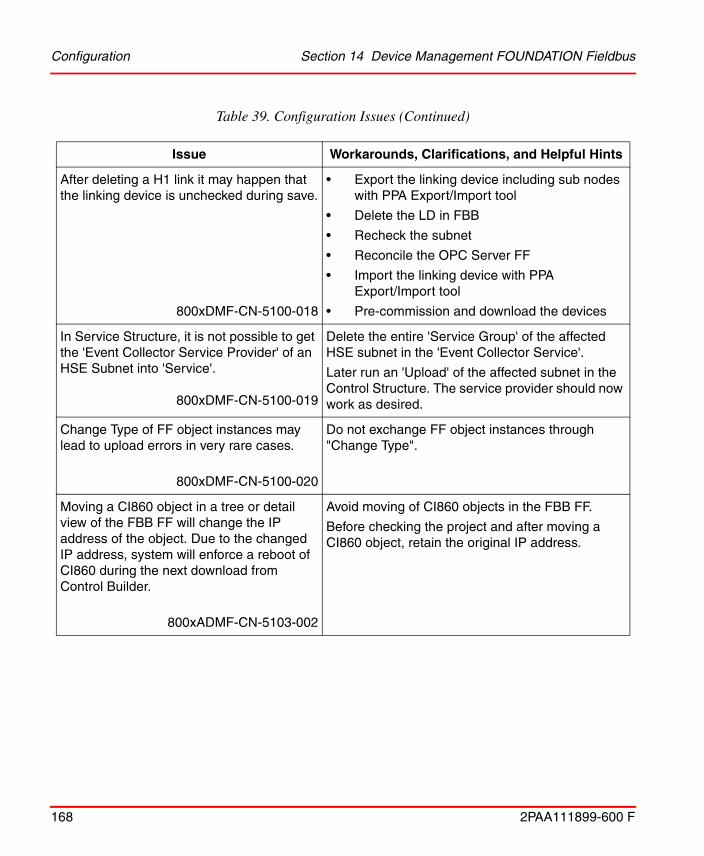
Configuration Section 14 Device Management FOUNDATION Fieldbus
168 2PAA111899-600 F
After deleting a H1 link it may happen that the linking device is unchecked during save.
800xDMF-CN-5100-018
• Export the linking device including sub nodes with PPA Export/Import tool
• Delete the LD in FBB
• Recheck the subnet
• Reconcile the OPC Server FF
• Import the linking device with PPA Export/Import tool
• Pre-commission and download the devices
In Service Structure, it is not possible to get the 'Event Collector Service Provider' of an HSE Subnet into 'Service'.
800xDMF-CN-5100-019
Delete the entire 'Service Group' of the affected HSE subnet in the 'Event Collector Service'.
Later run an 'Upload' of the affected subnet in the Control Structure. The service provider should now work as desired.
Change Type of FF object instances may lead to upload errors in very rare cases.
800xDMF-CN-5100-020
Do not exchange FF object instances through "Change Type".
Moving a CI860 object in a tree or detail view of the FBB FF will change the IP address of the object. Due to the changed IP address, system will enforce a reboot of CI860 during the next download from Control Builder.
800xADMF-CN-5103-002
Avoid moving of CI860 objects in the FBB FF.
Before checking the project and after moving a CI860 object, retain the original IP address.
Table 39. Configuration Issues (Continued)
Issue Workarounds, Clarifications, and Helpful Hints
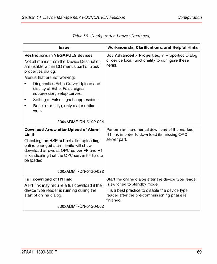
Section 14 Device Management FOUNDATION Fieldbus Configuration
2PAA111899-600 F 169
Restrictions in VEGAPULS devices
Not all menus from the Device Description are usable within DD menus part of block properties dialog.
Menus that are not working:
• Diagnostics/Echo Curve: Upload and display of Echo, False signal suppression, setup curves.
• Setting of False signal suppression.
• Reset (partially), only major options work.
800xADMF-CN-5102-004
Use Advanced > Properties, in Properties Dialog or device local functionality to configure these items.
Download Arrow after Upload of Alarm Limit
Checking the HSE subnet after uploading online changed alarm limits will show download arrows at OPC server FF and H1 link indicating that the OPC server FF has to be loaded.
800xADMF-CN-5120-022
Perform an incremental download of the marked H1 link in order to download its missing OPC server part.
Full download of H1 link
A H1 link may require a full download if the device type reader is running during the start of online dialog.
800xADMF-CN-5120-002
Start the online dialog after the device type reader is switched to standby mode.
It is a best practice to disable the device type reader after the pre-commissioning phase is finished.
Table 39. Configuration Issues (Continued)
Issue Workarounds, Clarifications, and Helpful Hints

Configuration Section 14 Device Management FOUNDATION Fieldbus
170 2PAA111899-600 F
FF object merge instead of exchange during import or deploy of FF configuration parts
In cases where an import or deploy should replace FF configuration parts, it may happen that the replaced parts are not removed.
800xADMF-CN-5120-005
Before importing or deploying FF configuration parts, the parts that would be replaced should be deleted.
Online version check not finished
Occasionally it may happen that the online version check is not complete due to an outstanding response from a H1 device, in this case the progress indicator for the online version check will be frozen.
800xADMF-CN-5120-010
Close the progress indicator dialog box manually after it is inactive for 90 sec.
After restore it may happen that a plausibility check will not eliminate all error indicators.
800xADMF-CN-5101-008
Reserve the whole subnet. Check the project manually multiple times until no more error indicators occur. Start download of Control Builder M only after subnet has been uploaded.
After function blocks have been deleted, the version check within the Online dialog shows that the config has changed. The following download action runs without error, but the download arrow icon on the link in the hardware tree still remains. A new online version check still reports that the config has changed.
800xDMF-CN-5100-002
Perform a full download.
Table 39. Configuration Issues (Continued)
Issue Workarounds, Clarifications, and Helpful Hints

Section 14 Device Management FOUNDATION Fieldbus Configuration
2PAA111899-600 F 171
Check after import fails with error message:
“The signal <signal name> is not a FF signal”.
800xDMF-CN-5100-004
Open corresponding FBAD, select the red indicated signals and click Enter. Occasionally the signal properties dialog may occur and needs to be confirmed. The former red marked signals now appear in black color.
Commissioning
Moving a device in the tree view of the FF Object Editor, also inside a single tree, forces a full download of this device.
800xDMF-CN-4100-015
Avoid moving of devices in the tree view for optical reasons.
Factory Reset Not Indicated in Fieldbus Builder FF
If a device is reset using the RESTART parameter in the resource block, this has no influence on the displayed assignment and download state in the tree structure of the FF Object Editor.
800xDMF-CN-4100-017
Use the context menu of the device to initiate a factory reset.
Restarting an H1 device by writing the RESTART parameter in the Resource Block parameter dialog may time out with an error after 60 seconds.
800xDMF-CN-4100-019
For restarting an H1 device select the Restart device context menu entry at the H1 Device object.
Table 39. Configuration Issues (Continued)
Issue Workarounds, Clarifications, and Helpful Hints

Configuration Section 14 Device Management FOUNDATION Fieldbus
172 2PAA111899-600 F
Assignment of a pre-configured H1 device may fail in the following cases:
Case 1:
Assignment of an H1 device where the tag name and node address already match, may fail in rare cases with the message ’Error writing FBAP Server VCR’
Case 2:
Assignment of an H1 device which supports instantiable blocks and which has been pre-configured with a 3rd party configuration tool supporting configuration of instantiable blocks, may fail.
Case 3:
Assignment of an H1 device with Softing stack version < 2.11 may fail, if the device was configured with a 3rd party configuration tool or in another project before and Publisher/Subscriber VCRs were active in the device. The device assignment does not finish.
800xDMF-CN-4100-020
Workaround for Case 1:
Perform a Clear Address and then repeat the device assignment.
Workaround for Case 2:
Perform a factory reset of the H1 device using hardware means described in the user manual of the device. Then repeat the device assignment
Workaround for Case 3:
Power down and power up the device. Then repeat the device assignment. Alternatively perform a factory reset and then repeat the device assignment.
OPC Server interfere Fieldbus Builder FF download
During download it may occasionally happen that the OPC Server interfere FBB FF on writing to FBAP. In some cases this may prevent a successful download.
800xDMF-CN-5010-002
Retry download or retry download with a different download scope.
Table 39. Configuration Issues (Continued)
Issue Workarounds, Clarifications, and Helpful Hints

Section 14 Device Management FOUNDATION Fieldbus Configuration
2PAA111899-600 F 173
Device fails to download and connect
Function Block Application Process Virtual Field Device (FBAP VFD) access is not possible after download by inconsistent code generation.This shows up with capabilities file which include a section like [NM VCR Usage 2]FasDllResidualActivitySupported=RESIDUAL)
800xDMF-CN-5010-005
Patch the capabilities file: Remove the entry on all but the F8 server VCR or Replace RESIDUAL with NORESIDUAL.
CI860 will reboot after change of IP configuration (IP address, HSE Default Gateway or HSE Subnet mask)
- Immediately if client/server signals are already configured or
- Unexpectedly at a later time during downloading of any signal configuration changes.
800xADMF-CN-5101-006
Avoid changing the IP configuration of CI860.
If it cannot be avoided, force an immediate download by any signal configuration change.
System and Plant Explorer Handling
The system synchronization rollback does not restore the FF library. Devices will not be removed from a library.
800xDMF-CN-4100-025
No workaround exists for this issue.
Table 39. Configuration Issues (Continued)
Issue Workarounds, Clarifications, and Helpful Hints

Configuration Section 14 Device Management FOUNDATION Fieldbus
174 2PAA111899-600 F
No Online Access to HSE Subnet after Disconnecting HSE Subnet from One Node of a Redundant Pair of Connectivity Servers FF
Disconnecting the HSE Subnet from one node of a pair of redundant Connectivity Servers FF may disable online access of Fieldbus Builder FF to the HSE Subnet. Thus communication between Fieldbus Builder FF and the HSE Subnet is interrupted for the time of disconnection.
800xDMF-CN-5000-004
For accessing the HSE Subnet, Fieldbus Builder FF uses the first available Connectivity Server FF with DMS connection regardless of the HSE connection state of this node.
Workaround:
Reconnect HSE Subnet to Connectivity Server FF.
Bulk Data Manager
It is not possible to create FF objects and parameterize them in the same step with Bulk Data Manager (BDM). A second save creates a BDM error sheet.
800xDMF-CN-5100-009
After first save, read the just imported FF objects into the same Excel sheet. The original specified values are overwritten. Re-enter the correct values and save the BDM sheet again.
Or
Create separate BDM sheets: one for object creation and one for parameterization.
Table 39. Configuration Issues (Continued)
Issue Workarounds, Clarifications, and Helpful Hints

Section 14 Device Management FOUNDATION Fieldbus Operation
2PAA111899-600 F 175
Operation
Table 40 lists the issues that may exist and affect operation of the system or product at time of release. Workarounds, clarifications, or helpful hints have been provided for each issue wherever possible.
Table 40. Operational Issues
Issue Workarounds, Clarifications, and Helpful Hints
Crash of OPC server in Trace Module
The OPC servers FF may crash in the Trace Module after a loop in the Ethernet network creates a high broadcast load.
800xADMF-OL-5101-016
Avoid loops in the Ethernet network.
On cancelling a download the OPC server FF displays No Connection
On cancelling a download, the OPC server FF may display No Connection in the tree view.
800xADMF-OL-5120-009
Reboot the connectivity server or perform the following steps:
1. Close all Fieldbus Builder FF applications on all the nodes.
2. In the Service Structure of the Workplace stop both OPC service provider (Event Collector and OPCDA) of the Subnet.
3. Restart the ABB FFNameserver in Windows Services (Use Task Manager).
4. Enable Service providers again in Service Structure that is stopped in the Step 2.

Operation Section 14 Device Management FOUNDATION Fieldbus
176 2PAA111899-600 F
Fieldbus Builder FF Crashes in Diagnostic View
Fieldbus Builder FF crashes after the following sequence:
• Diagnostic View is selected.
• OPC Server Object or HSE Host Object (CI860) is selected in Tree View.
• Switched back in Tree View to Object other than those before (HSE Subnet, LD or H1 link).
• Mouse click in Device List View (anywhere).
800xADMF-OL-5120-012
Do not select OPC Server Object or HSE Host Object (CI860) in Tree View when the Diagnostic View is displayed.
Select the Device List Tab before selecting those objects.
The FBBFF shuts down while changing to commissioning mode, if duplicate IP addresses are used on the HSE network.
800xADMF-OL-5130-003
Avoid duplicate IP addresses on the HSE network.
Frozen or Bad values in Faceplates, Graphics, and Trends Properties such as OPC Control Connection/OPC Control Connection.xxxxx from FF objects used in BDM sheets may lead to frozen or bad OPC values in faceplates, graphics, and trends.
800xADMF-OL-5103-001
Do not use properties such as OPC Control Connection/OPC Control Connection.xxxxx from FF objects in BDM sheets if plant is in operation.
Table 40. Operational Issues (Continued)
Issue Workarounds, Clarifications, and Helpful Hints

2PAA111899-600 F 177
Section 15 Device Management PROFIBUSand HART
Known ProblemsThis section details the Known Problems for the Device Management PROFIBUS and HART that exist in the system at the time of release.
Administration
Table 41 lists the issues that may exist and affect administration at time of release including user, node, and service structure related problems. Workarounds, clarifications, or helpful hints have been provided for each issue wherever possible.
Table 41. Administration Issues
Issue Workarounds, Clarifications, and Helpful Hints
Re-authentication does not work for Device Management and Fieldbus Management. The Re-Authentication window will be shown when HART device objects are created or deleted and Re-Authentication is enabled.
800xDPH-AD-5000-001
Re-Authentication for HART and PROFIBUS device type objects has been disabled in this version by default.
Do not enable it.

Configuration Section 15 Device Management PROFIBUS and HART
178 2PAA111899-600 F
Configuration
Table 42 lists the issues that may exist and affect configuration of the system or product at time of release. Workarounds, clarifications, or helpful hints have been provided for each issue wherever possible.
Asset Monitor for ABB device type objects show an error in top most line.
800xDPH-AD-5000-006
Even if the Asset Monitor shows an error within the topmost line, it works correctly regarding the mandatory parameters and conditions from the device. The error is forced by optional device parameters which are not used by the Asset Monitor.
After a firmware download to an AC 800M controller the OPC Server PROFIBUS/HART will sometimes stop operation.
800xADPH-AD-5020-011
After a firmware download to an AC800M controller is performed reboot the corresponding Connectivity Server when OPC Server PROFIBUS/HART runs at this node.
This affects only OPC Server PROFIBUS/HART which are connected to AC 800M controllers.
When PROFIBUS/HART OPC server is configured in redundancy it might happen that for sometime (Around 10 minutes) both the OPC servers are activated during runtime. This will cause more number of connection to controller. As a result, connection to some devices might be aborted.
800xADPH-AD-5020-012
Increase the number of Tool Routing connection in controller from default 20 to a higher number 30. No user action is required when OPC servers are running in parallel. System behavior comes back to normal after sometime (about 10 minutes).
Table 41. Administration Issues (Continued)
Issue Workarounds, Clarifications, and Helpful Hints

Section 15 Device Management PROFIBUS and HART Configuration
2PAA111899-600 F 179
Table 42. Configuration Issues for Device Management PROFIBUS & HART
Issue Workarounds, Clarifications, and Helpful Hints
Soft Alarm Service goes in to the error state after system restart if it is launching DeviceManagementServer process while startup.
800xDPH-CN-5100-037
Open the Plant Explorer Workplace on Aspect Server node for which Soft Alarm Service is configured.
Disable and Enable the Soft Alarm Service again. Keep the Plant Explorer Workplace open till Soft Alarm Service goes to service state.
If control entity is reserved by any other user than the logged in user, ABB third party DTMs does not show any DTM view.
800xDPH-CN-5100-017
This is DTM specific Implementation. No workaround exists for this issue.
When DTM is opened or accessed by right-clicking on Device instance in Control Structure without reserving the entity, the same DTM cannot be accessed again with user role 'Planning Engineer' after reserving the entity.
800xDPH-CN-5100-029
Close and reopen the Plant Explorer Workplace and then access the DTM with entity reserved.
or
Before accessing the DTM, release the Control project from Controller level and reserve it again.
In Basic HART DTM, company name will be shown as blank if connected HART 7 device has 2 byte manufacturer ID.
800xADPH-CN-5100-014
No workaround exists for this issue.

Configuration Section 15 Device Management PROFIBUS and HART
180 2PAA111899-600 F
Deploy while branch is online at the same node is not possible
A Deploy while fieldbus subtree is online at the same node generates an error message: "This action is not possible..... is online".
800xDPH-CN-5020-005
End running online operation and try Deploy again.
Inconsistent data after re-configuration of the Fieldbus Builder PH OPC.
After re-configuration of the Fieldbus Builder PH OPC the server deliver inconsistent data, e.g. wrong quality state if the time stamp of the server topology file is not equal or newer than the re-configuration accomplishing time.
The re-configuration accomplishing time is displayed in the Fieldbus Management dialog and the topology file “TopologyImExport.xml” is saved in the folder “C:\Program Files(x86)\ABB Industrial IT\Engineer IT\FieldbusBuilder\OPCServerConfig”.
800xDPH-CN-5020-010
After re-configuration (e.g. changes in the topology) of the Fieldbus Builder PH OPC perform a restart of the OPC Server:
1. Disable the Service Provider for the Fieldbus Builder PH OPC in the Service Structure. Note that shutdown of the Fieldbus Builder PH OPC takes time (3-4 minutes)
2. Ensure that the following processes are terminated:
– abbfdtopc.exe
– abbsrvcc800xA.exe
3. After that enable the Service Provider for the Fieldbus Builder PH OPC in the Service Structure again.
Last restore information (Date and timestamp) in FBB Filesync Helper aspect is not available.
800xADPH-CN-5100-002
No impact on functionality. Check configuration wizard log file for this information.
Table 42. Configuration Issues for Device Management PROFIBUS & HART (Continued)
Issue Workarounds, Clarifications, and Helpful Hints

Section 15 Device Management PROFIBUS and HART Configuration
2PAA111899-600 F 181
If the system is upgraded to later versions, the Calibration Event List aspect may be available on Control Network object instance and ABB Generic HART Transmitter object instances in Control Structure. If DMS Calibration Connect System Extension is not loaded, then this aspect will remain unconfigured.
From 800xA system version 5.1 onwards, due to unconfigured calibration event list aspect, following issues can occur:
1. If such aspect is present in any object, then it will not be possible to browse 800xA OPC server (AfwOpcDaSurrogate). For more information, refer to Product Bulletin 3BSE066045.
2. Consistency checker tool will also report the error about unconfigured calibration event list aspect.
3. When user clicks on Calibration Event List aspect, it opens with following message:
"Could not connect to the configuration aspect. Please look at the configuration"
However, user will not find any configuration to look at.
800xADPH-CN-5100-005
If DMS Calibration Connect is not in use, delete Calibration Event List aspect from Control Network object instance and ABB Generic HART transmitter object instance in Control Structure.
Table 42. Configuration Issues for Device Management PROFIBUS & HART (Continued)
Issue Workarounds, Clarifications, and Helpful Hints

Configuration Section 15 Device Management PROFIBUS and HART
182 2PAA111899-600 F
Replacing IO module in Control Builder M by using Replace Unit menu option cause the problem such as Device Management aspect referring to old IO Module DTM or Invalid topology data. DTM out of order? message in Fieldbus Management aspect of the replaced IO module.
800xDPH-CN-5100-031
Delete the IO module instance and Insert Unit as required.
Selecting Documentation menu for Generic HART DTM does not open user manual. This problem occurs only on the system upgraded from any 800xA System version on 32 bit operating system to 64 bit operating system with device instance created prior to system upgrade.
800xDPH-CN-5100-021
Apply the below mentioned workaround to all the device instances to resolve the problem.
1. Select Configuration user interface from Device Management aspect or from Device Functions menu for a device instance.
2. In Configuration user interface, select the Documentation tab.
3. Browse and select the correct path for Documentation Link as (C:\Program Files(x86)\ABB Industrial IT\Engineer IT\DTM\Basic HART DTM\Doc\3BDD011939-510_A_en_Device_Management_Basic_HART_DTM_5.2.pdf)
4. Click OK or Apply to save the changes.
In Control Builder M it is possible to move already placed modules from one slot to another slot, but the opened identification view of S800 DTM is not updated. It still shows the old position.
800xDPH-CN-5000-012
Close and reopen the S800 DTM user interface.
Table 42. Configuration Issues for Device Management PROFIBUS & HART (Continued)
Issue Workarounds, Clarifications, and Helpful Hints

Section 15 Device Management PROFIBUS and HART Configuration
2PAA111899-600 F 183
The Observer GUI of the AI830 DTM is not displaying the channel value, bar graph for the channels configured with all available signal ranges.
800xADPH-CN-5100-027
No workaround exists for this issue.
Two Objects with the same name under HART Multiplexer Subnet do not result in errors, but may lead to identification problems. Therefore it is recommended to use unique names.
800xDPH-CN-5000-016
Double names do not result in errors, but may lead to identification problems. Therefore use unique names.
When clicking on 'Multiplexer Assignment' in the HART Multiplexer DTM of HART Multiplexer Connect the expected DTM Windows may not appear.
800xDPH-CN-5000-038
The window for the Assignment is appearing in the Windows Taskbar (background).
Table 42. Configuration Issues for Device Management PROFIBUS & HART (Continued)
Issue Workarounds, Clarifications, and Helpful Hints

Configuration Section 15 Device Management PROFIBUS and HART
184 2PAA111899-600 F
Wireless HART solution for wired HART positioner is not available.
800xDPH-CN-5100-004
Currently, the solution is available only for Wired HART Transmitters and Wireless HART Devices.
Event List shows continuous File Set Distribution (FSD) events with a message as 'InvalidItem' for the Fileset representing the file that belong to Fieldbus Builder PH.
The FSD event has a description as below:
“Fileset is invalid. Reason: Filename already exists. Fieldbus Builder PH Cache\.....”.
800xDPH-CN-5100-036
For workaround and more information, please contact the ABB technical support.
Table 42. Configuration Issues for Device Management PROFIBUS & HART (Continued)
Issue Workarounds, Clarifications, and Helpful Hints

Section 15 Device Management PROFIBUS and HART Operation
2PAA111899-600 F 185
Operation
Table 43 lists the issues that may exist and affect operation of the system or product at time of release. Workarounds, clarifications, or helpful hints have been provided for each issue wherever possible.
Table 43. General Operational Issues
Issue Workarounds, Clarifications, and Helpful Hints
Some times during upload operations for HART 7 devices using Basic HART DTM,
“9 - Invalid Selection” error message may appear and upload may fail.
800xDPH-OL-5100-013
1. Open Basic HART DTM.
2. In the Observation UI, change the variable codes not supported by the device in the default list under Device Variable with Status > Variable code.
3. Press Read.
4. Perform the upload operation.
In the Basic HART DTM Wireless Configuration user interface, Join status field shows Join status code instead of Join status description.
800xDPH-OL-5100-014
Refer to Flow of Join status Information area in the Basic HART DTM Wireless Configuration user interface.
The Device Type Manager (DTM) for ABB Instruments (except S800 IO, S900 IO and Basic HART DTM) does not up-/download the complete parameter data-set, if the up-/download is started via Fieldbus Management Aspect.
800xDPH-OL-5000-019
Complete up-/download of device parameter data-set must be initiated directly in the specific DTM. Open the DTM of the specific device, change the parameter (if applicable) and start download/upload from the DTM menu.
Disable Communication via Fieldbus Management aspect while an online DTM window is still open may result in failed release communication call.
800xADPH-OL-5000-035
Close all open online DTM windows before disabling the communication via Fieldbus management aspect.

Operation Section 15 Device Management PROFIBUS and HART
186 2PAA111899-600 F
If a project is taken over from another node or the Load-Evaluate-Go action is performed, then several communication related error messages (for example, ..communication failed..) are displayed.
800xDPH-OL-5010-001
Take Over a project from another node or Load- Evaluate-Go should only performed if the Fieldbus Management is in Communication disabled mode (offline).
The generic HART Asset Monitor loaded in the AO Server could show an inconsistency condition for Configuration Changed.
The Configuration Changed condition in the generic HART Asset Monitor is active, but there was no change in the device configuration via DTM or handheld.
The Configuration Changed condition is not reset, if the device and the instance data set have been synchronized.
800xDPH-OL-5010-003
Open Plant Explorer Workplace Aspect System Structure with system administrator rights.
Navigate to Asset Monitoring, Aspect system -> Asset Monitors, Aspect type. -> HART Generic Device Asset Monitor, Aspect category.
Select the aspect “HART Generic Device Asset Monitor”.
Open the tab "Input Records" and set for all optional input records in the column “Data Source Aspect” the entry to "None". Click Apply to confirm the changes.
Control structure out of sync message while working with DTMs specially when using Wireless HART or HART Multiplexer connect.
800xADPH-OL-5100-001
Close and re-open 800xA workplace (before re-opening 800xA workplace, ensure that the Device Management process is closed).
Sometimes there may be an entry 'Invalid item ID' in Eventlist after performing operations on Fieldbus Management aspect for example, Upload or Download.
800xADPH-OL-5100-009
Ignore the messages as they have no impact on Fieldbus Builder PH functionality.
Table 43. General Operational Issues (Continued)
Issue Workarounds, Clarifications, and Helpful Hints

Section 15 Device Management PROFIBUS and HART Operation
2PAA111899-600 F 187
It is observed that if Online DTM GUI is kept open for 10 - 12 hours, then DeviceManagementServer process crashes.
800xADPH-OL-5100-021
It is recommended to close the DTM GUI after usage.
If this issue occurs, close and reopen the Plant Explorer Workplace.
If a HART device fails during a download the progress bar does not stop, and no retry of the download, and no connection to the Device is possible.
800xDPH-OL-5000-023
The user must cancel the download function manually (in the Fieldbus Management View select the context menu “Cancel Download”).
In case Wireless HART Gateway is power recycled, all the adapters may not join the network afterwards.
800xDPH-OL-5100-003
Power recycle the adapters which do not join the network.
Sometimes two wired HART devices may appear under one Adapter in Gateway Webpage. This might happen after replacing the wired device under the adapter or moving it to another adapter.
800xDPH-OL-5100-004
Delete the devices in Gateway Webserver which are not physically connected to the Wireless HART Adapter.
Table 43. General Operational Issues (Continued)
Issue Workarounds, Clarifications, and Helpful Hints

Operation Section 15 Device Management PROFIBUS and HART
188 2PAA111899-600 F
Following general limitations of Pepperl + Fuchs Wireless HART Gateway should be
considered:
1. Gateway communication via RS485 serial interface not supported. This means
MODBUS RTU /Binary HART over RS485 connectivity is not possible.
2. Gateway webserver is supported from Internet Explorer version 8.0 onwards.
3. DHCP/DNS client functionality will not be supported. Only manual configuration of
Gateway IP address is supported.
800xDPH-OL-5100-013
Refer Device_Management PROFIBUS and HART Configuration (3BDD011934*) manual for wireless Hart configuration in 800xA system.
Windows Event list is filled by the GPB DTM.
800xDPH-OL-5100-012
The DTM Events will fill the information Event. Ignore the entries or filter them out.
All the Datafields in Identification window of CI920 DTM are not updated in one cycle of communication if CI920 Firmware Version 1.4.2 is used.
800xDPH-OL-5100-006
Press Reread in Identification Window.
Table 43. General Operational Issues (Continued)
Issue Workarounds, Clarifications, and Helpful Hints

Section 15 Device Management PROFIBUS and HART Operation
2PAA111899-600 F 189
When Lower/Upper Limit values and Range Units are changed from Configuration window the values are not getting updated in the Identification window. In case of multinode operation changes made in Comments text box are also not getting updated.
800xDPH-OL-5100-007
Download the data and then perform an Upload operation to view the changed values in Identification window.
When a download operation is performed with parameter fields changed, the configuration change counter value in online parameterize Window should increase by 1 with each download operation. But the current field shows some negative value, which changes on each download.
800xDPH-OL-5100-008
Changes in configuration counter count can be observed when download operation is done.Change in value implies that some download operation has been done.
While working with HART Multiplexer DTMs, the List of Multiplexer User interface is not automatically updated if there is a disturbance. Eg.COM port is disconnected.
800xDPH-OL-5100-011
This problem is with update of DTM User interface and refreshing the Multiplexer list will show the correct status of Multiplexers. However there is no issue with Device DTM and Asset Optimization communication.
When working with Generic HART DTM, if plant Explorer is closed, while DTM GUI is still open in Online mode, then there may be an entry in PPA alarm and event list as 'Abort'.
800xADPH-OL-5100-005
Ignore the message.
Table 43. General Operational Issues (Continued)
Issue Workarounds, Clarifications, and Helpful Hints

Operation Section 15 Device Management PROFIBUS and HART
190 2PAA111899-600 F
During PROFIBUS cable disturbance FCI Module's (CI920) DTM switchover from Primary to Secondary takes time which affects Device DTM communication.
800xDPH-OL-5100-023
Disable and Enable Fieldbus Management Communication and perform upload/download.
If user stops FBB OPC Service when HART/PROFIBUS OPC cycles are running, ABBFDTOPC process will remain in Task manager.
800xDPH-OL-6000-001
If user wants to stop it immediately, terminate the process manually from Task Manager.
Table 43. General Operational Issues (Continued)
Issue Workarounds, Clarifications, and Helpful Hints

Section 15 Device Management PROFIBUS and HART Miscellaneous
2PAA111899-600 F 191
Miscellaneous
Table 44 list the problems or issues known to exist with the current release that do not fit into one of the other categories. Workarounds, clarifications, or helpful hints have been provided for each issue wherever possible.
Table 44. Miscellaneous Issues
Issue Workarounds, Clarifications, and Helpful Hints
Redundancy switch over of a Connectivity Server leads to “bad status” in the corresponding Asset Monitors for one OPC Server cycle.
800xADPH-MS-5010-002
Correct values are available from second OPC cycle onwards.
In Generic HART DTM Force window, If user sets to exceed lower / upper range values then Popup window should appear but it's not appearing.
800xADPH-MS-5010-003
When user sets value which exceed the lower / upper range values and press apply button, no message box pops up.But in the status bar it shows a message "No HART message received".The value then goes back to last valid value and user can continue with normal operations
Aspects of device instances created from device type objects will not be updated, if a new minor version of the device type object is installed via Device Library Wizard.
800xADPH-MS-5000-032
Device Type instances will be updated with functional aspects like Device Management aspects only. The device types cannot be recognized directly via name or type definition aspects.
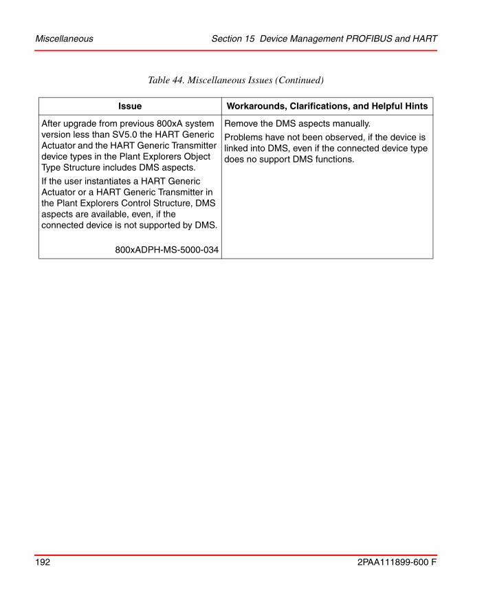
Miscellaneous Section 15 Device Management PROFIBUS and HART
192 2PAA111899-600 F
After upgrade from previous 800xA system version less than SV5.0 the HART Generic Actuator and the HART Generic Transmitter device types in the Plant Explorers Object Type Structure includes DMS aspects.
If the user instantiates a HART Generic Actuator or a HART Generic Transmitter in the Plant Explorers Control Structure, DMS aspects are available, even, if the connected device is not supported by DMS.
800xADPH-MS-5000-034
Remove the DMS aspects manually.
Problems have not been observed, if the device is linked into DMS, even if the connected device type does no support DMS functions.
Table 44. Miscellaneous Issues (Continued)
Issue Workarounds, Clarifications, and Helpful Hints

2PAA111899-600 F 193
Section 16 Device Library Wizard
Known ProblemsThis section details the Known Problems for the Device library Wizard that exist in the system at the time of release.
Operation
Table 45 lists the issues that may exist and affect operation of the system or product at time of release. Workarounds, clarifications, or helpful hints have been provided for each issue wherever possible.
Table 45. Operational Issues
Issue Workarounds, Clarifications, and Helpful Hints
Deletion of device types will result in orphaned object types when device types instances are directly used in any structure other than Control structure.
DLW will list such device types as deletable device types as it searches only to control structure if device type has been in use.
800xADLW-OL-5100-003
In such cases delete device types manually and don’t use DLW delete functionality.
DLW will list PROFIBUS libraries as deletable library even if the PROFIBUS library is just connected in Control builder and actually not being used.
800xADLW-OL-5100-004
Actual Delete will not be possible in this case. Disconnect the library first in Control builder and then use DLW delete functionality.

Operation Section 16 Device Library Wizard
194 2PAA111899-600 F
While Synchronizing bulk number of Device types or Device Libraries from Primary Aspect server to DLW Clients, Memory Consumption will shoot up momentarily.
800xADLW-OL-5100-005
Synchronization is copying Device types installed in Primary Aspect Server to DLW Clients. Momentary Memory peak is as per Standard Windows behavior during copying from one machine to other.
During Synchronization of Device types or Device Libraries from Primary Aspect server to DLW Clients, will hang in case of Network Disturbances
800xADLW-OL-5100-006
After restoring Network connections, Restart DLW Client.
TCP Error Time Out (Network Disturbance Error log) will appear after 10 minutes and this is as per Standard TCP-IP Protocol behavior.
During Device Type Restore, User will find device types (available in 800xA Workplace) under both Restore & Install tab
800xADLW-OL-5100-007
While Restoring Device types user need to select the Device types which is available in 800xA Workplace.
While installing the FF object types through DLW user may get an error message " Error! failed updating AFW!, COM error = Unspecified error"
800xADLW-OL-5100-008
The Error message is due to FF builder goes to locked state. The user can unlock the same by navigating to the following path
Service structure-> FFDataStorageAndDistribution,Service -> Basic, Service Group and select the aspect Service Group Definition. Under Service group definition select the Special Configuration tab and break the lock for all the entries by right click on the same
Table 45. Operational Issues (Continued)
Issue Workarounds, Clarifications, and Helpful Hints

2PAA111899-600 F 195
Section 17 Asset Optimization
Known ProblemsThis section details the Known Problems for Asset Optimization, that exist in the system at the time of release.
Installation
Table 46 lists issues that may exist and affect the installation and upgrade of the system or product at time of release. Workarounds, clarifications, or helpful hints have been provided for each issue wherever possible.

Installation Section 17 Asset Optimization
196 2PAA111899-600 F
Table 46. Installation Issues
Issue Workarounds, Clarifications, and Helpful Hints
The following error is observed during Asset Optimization software installation on the AO Server Node, while installing the COM+ Components:
Couldn’t register COM+ Component….
At the same time following events are logged in the Windows Application Event Log.
Faulting application MsiExec.exe, version 4.5.6002.18005, time stamp 0x49e01c42, faulting module OptaoClientUtils.dll_unloaded….
800xASRV-OL-5102-001
This issue is observed in rare instances, perform the following steps to solve this problem:
1. Click OK to acknowledge the message and continue with the installation of the remaining products using the System Update Tool.
2. After completing the installation,
• Start > Control Panel > Programs and Features.
• Select ABB Asset Optimization software and click Uninstall.
• Select Remove from the installation dialog box and complete the uninstallation of the software.
3. This software is accessible from the Installation Launchpad by selecting:
Manual Installation > Applications > Asset Optimization
4. Follow the Installation Wizard to complete the installation.
5. Setup Type dialog box: Make the selection based on the following:
• Select Server to install AO Server components on all Asset Optimization Server nodes.

Section 17 Asset Optimization Configuration
2PAA111899-600 F 197
Configuration
Table 47 lists the issues that may exist and affect configuration of the system or product at time of release. Workarounds, clarifications, or helpful hints have been provided for each issue wherever possible.
Replacing node using SCC for "Asset Optimization Services Additional" is creating a duplicate service group in system.
800xAASO-IN-6000-001
The service state of the originally existed service group is going into Error state. Delete the following Service Group which is in Error State.
• An AO Server object located in the Control Structure under the Asset Optimization parent node.
• An AssetMonitoring Service Group and related Service Provider in the Service Structure.
Table 47. Configuration Issues
Issue Workarounds, Clarifications, and Helpful Hints
If an incorrectly configured Asset Monitor Data Source is (or was) used by a loaded Asset Monitor, an Asset Optimization Server will report the following error message:
“AM Engine Running, DataSources Status: ‘Asset Optimization:BAD Asset Monitor Data Source’ data source error, will try to reconnect in one minute.”
800xAASO-CN-5000-006
Perform one of the following:
• Properly configure the Asset Monitor Data Source and reload the Asset Monitor using it.
• If no Asset Monitors are configured to use the improperly configured Asset Monitor Data Source, perform a Load all AMs operation from the Asset Monitors tab of the Asset Optimization Server aspect. This will remove the improperly configured Asset Monitor Data Source from the Asset Optimization Server.
There will be no further retry of connection to unused dataserver(s) by data engine.
Table 46. Installation Issues (Continued)
Issue Workarounds, Clarifications, and Helpful Hints

Operation Section 17 Asset Optimization
198 2PAA111899-600 F
Operation
Table 48 lists the issues that may exist and affect operation of the system or product at time of release. Workarounds, clarifications, or helpful hints have been provided for each issue wherever possible.
Table 48. Operational Issues
Issue Workarounds, Clarifications, and Helpful Hints
While inserting an Object in an Asset Structure, sometimes it is observed that the Asset Viewer propagated status shows last updated status for objects with Asset Monitor that are inserted into the Asset Structure.
800xAASO-OL-5140-010
Re-insert those Objects having Asset Monitors or restart the AssetTree service located in the Service Structure.
To restart:
1. Under Service Structure, Service, go to AssetTree, Service and then expand AssetTree SG_1, Service Group.
2. Click AssetTree SP_1, Service Provider.
3. Select Service Provider Definition from the Aspect list on the right-hand pane.
4. Clear the selection in Enabled check box to disable and then check it again to restart the AssetTree Service.
When an equipment ID or Asset Monitor aspect is changed after fault report defaults are created, the changes are not updated in the fault report defaults.
800xAASO-OL-5100-001
Recreate the fault report defaults.

2PAA111899-600 F 199
Section 18 PC, Network and SoftwareMonitoring
Known ProblemsThis section details the Known Problems for PC, Network and Software Monitoring that exist in the system at the time of release. It also enumerates known problems encountered in the final testing of this product release and identifies workarounds that help overcome the problem.
Configuration
Table 49 lists the issues that may exist and affect configuration of the system or product at time of release. Workarounds, clarifications, or helpful hints have been provided for each issue wherever possible.

Configuration Section 18 PC, Network and Software Monitoring
200 2PAA111899-600 F
Table 49. Configuration Issues
Issue Workarounds, Clarifications, and Helpful Hints
Rarely observed that the Generate operation from "IT Device Manager" aspect or Create operation from "IT General setup" aspect creates Asset Monitor as "Object name [IT Asset object type, IT Asset Monitor] aspect.
During the generate operation the following error message appears:
"[Error] Asset Monitor name "Object name [IT Asset object type, IT Asset Monitor]" is not unique for [Control Structure]Root/IT Server/object name. Transaction Cancelled.
During Create operation, the Plant Explorer closes.
800xAPNS-CN-5100-001
In the Plant Explorer, use the Find tool to search for the *[*,IT Asset Monitor] aspect in Control Structure.
Identify all "Object name:object name [IT Asset object type,IT Asset Monitor]" in the list. Right- click and delete the aspects.
Perform the Create/Generate operation again.
Basic Computer Asset cannot generate the Alarm messages of potential workstation resource problems.
800xAPNSM-CN-5100-002
Do not delete the Alarms generated during Basic Computer Asset Object creation.

2PAA111899-600 F 201
Section 19 Batch Management
Known ProblemsThis section details the Known Problems for Batch Management, that exist in the system at the time of release.
Installation
Table 50 lists issues that may exist and affect the installation and migration of the system or product at time of release. Workarounds, clarifications, or helpful hints have been provided for each issue wherever possible.
Table 50. Installation Issues
Issue Workarounds, Clarifications, and Helpful Hints
Missing configuration is causing Batch Redundancy not to work. This occurs when expanding systems with redundant services that have been previously deployed with Batch Primary services and Client Nodes. The configuration tool will appear to have successfully deployed even though the configuration is not correct.
800xAPMB-IN-6000-012
Create the ODBC Connection on all nodes after the deployment is complete.
Launch command prompt as Administrator and Navigate to
<Installed drive>\Program Files(x86)\ABB Industrial IT\Produce IT\Batch\bin
Run BatchDSNUtility.exe <PrimaryNodeName> <SecondaryNodeName>
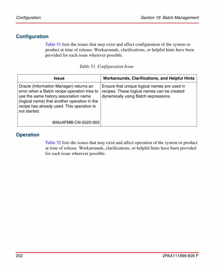
Configuration Section 19 Batch Management
202 2PAA111899-600 F
Configuration
Table 51 lists the issues that may exist and affect configuration of the system or product at time of release. Workarounds, clarifications, or helpful hints have been provided for each issue wherever possible.
Operation
Table 52 lists the issues that may exist and affect operation of the system or product at time of release. Workarounds, clarifications, or helpful hints have been provided for each issue wherever possible.
Table 51. Configuration Issue
Issue Workarounds, Clarifications, and Helpful Hints
Oracle (Information Manager) returns an error when a Batch recipe operation tries to use the same history association name (logical name) that another operation in the recipe has already used. This operation is not started.
800xAPMB-CN-5020-003
Ensure that unique logical names are used in recipes. These logical names can be created dynamically using Batch expressions.

Section 19 Batch Management Operation
2PAA111899-600 F 203
Table 52. Operational Issues
Issue Workarounds, Clarifications, and Helpful Hints
A VB runtime error 91 is displayed if the Excel sheet is closed during loading of parameters in Batch Spreadsheet Scheduler.
800xAPMB-OL-5110-002
Close and re-open the Microsoft Excel sheet.
Unable to schedule Batch from the Scheduler Aspect as the default cell is unavailable and the Batch cell is invisible in the main view of the Scheduler Aspect.
800xAPMB-OL-5130-035
If the default cell is unavailable for a Procedure, make the Batch Cell field visible from the Config View of the Batch Scheduler Aspect.
Harmony communications can fail to write commands from the Batch Manager to the control logic in the Harmony controller. This failure generates a Batch Alarm. The Batch Recipe will stall on the active block experiencing the communication error and the Recipe Procedure block will turn red indicating an error.
Navigate into the Batch Recipe PFC and select the Block
Status of the recipe procedure block experiencing the error.
If the block in error is a Compute BMA (Batch Manager Action) use the Start @ Beginning command to retry the
compute expression.
If the block in error is a Phase, Open the block status of the Phase in error and select either the Start @ Beginning or
Continue @ Next command depending on the error shown in the block status Errors field.
Conditions that indicate the Phase failed to start and a Start@ Beginning Command is needed:
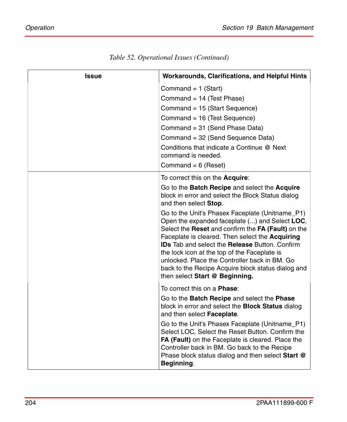
Operation Section 19 Batch Management
204 2PAA111899-600 F
Command = 1 (Start)
Command = 14 (Test Phase)
Command = 15 (Start Sequence)
Command = 16 (Test Sequence)
Command = 31 (Send Phase Data)
Command = 32 (Send Sequence Data)
Conditions that indicate a Continue @ Next command is needed.
Command = 6 (Reset)
To correct this on the Acquire:
Go to the Batch Recipe and select the Acquire block in error and select the Block Status dialog and then select Stop.
Go to the Unit's Phasex Faceplate (Unitname_P1) Open the expanded faceplate (...) and Select LOC, Select the Reset and confirm the FA (Fault) on the Faceplate is cleared. Then select the Acquiring IDs Tab and select the Release Button. Confirm the lock icon at the top of the Faceplate is unlocked. Place the Controller back in BM. Go back to the Recipe Acquire block status dialog and then select Start @ Beginning.
To correct this on a Phase:
Go to the Batch Recipe and select the Phase block in error and select the Block Status dialog and then select Faceplate.
Go to the Unit's Phasex Faceplate (Unitname_P1) Select LOC, Select the Reset Button. Confirm the FA (Fault) on the Faceplate is cleared. Place the Controller back in BM. Go back to the Recipe Phase block status dialog and then select Start @ Beginning.
Table 52. Operational Issues (Continued)
Issue Workarounds, Clarifications, and Helpful Hints
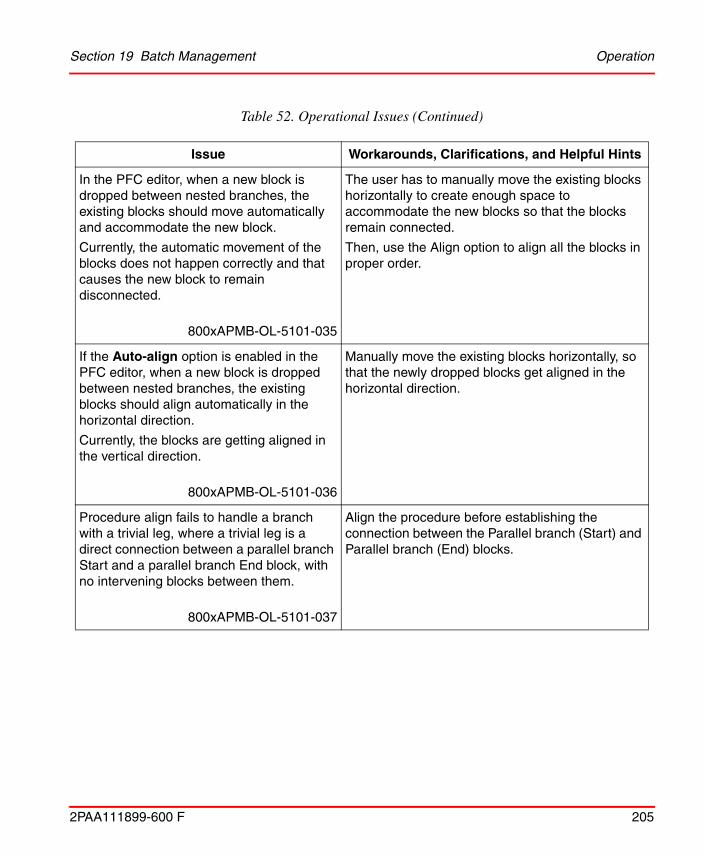
Section 19 Batch Management Operation
2PAA111899-600 F 205
In the PFC editor, when a new block is dropped between nested branches, the existing blocks should move automatically and accommodate the new block.
Currently, the automatic movement of the blocks does not happen correctly and that causes the new block to remain disconnected.
800xAPMB-OL-5101-035
The user has to manually move the existing blocks horizontally to create enough space to accommodate the new blocks so that the blocks remain connected.
Then, use the Align option to align all the blocks in proper order.
If the Auto-align option is enabled in the PFC editor, when a new block is dropped between nested branches, the existing blocks should align automatically in the horizontal direction.
Currently, the blocks are getting aligned in the vertical direction.
800xAPMB-OL-5101-036
Manually move the existing blocks horizontally, so that the newly dropped blocks get aligned in the horizontal direction.
Procedure align fails to handle a branch with a trivial leg, where a trivial leg is a direct connection between a parallel branch Start and a parallel branch End block, with no intervening blocks between them.
800xAPMB-OL-5101-037
Align the procedure before establishing the connection between the Parallel branch (Start) and Parallel branch (End) blocks.
Table 52. Operational Issues (Continued)
Issue Workarounds, Clarifications, and Helpful Hints

Operation Section 19 Batch Management
206 2PAA111899-600 F
Adding parameter(s) to a phase when the library and applications are not reserved in Control Builder causes the phase parameter to be added to the Object Type of the phase. But, the phase parameter fails to get written to instances. This generates an error message that the parameter could not be added.
When the proper steps are followed after the failure, the same error gets generated.
800xAPMB-OL-5101-039
Always reserve the library and application. This will ensure that there are no consistency issues.
The PFC Editor may stop responding while configuring and saving when there are large numbers of blocks.
800xAPMB-OL-5101-040
Edit the crashed Procedure. A message Do you want to reload the unsaved changes is displayed.
Click Yes.
Information of all the configured blocks will be reloaded into the editor, except for the last configured block.
While editing multiple attributes in the runtime grid view, if the Limited Low and Limited High are lower or higher than the current InValue, then the grid view is cleared, but the Limited High and Limited Low values get retained.
After this state, if the InValue is changed to a value within the new Limited High and Limited Low and saved, then the cleared values are saved as the new Limited Low or Limited High value.
800xAPMB-OL-5101-042
When editing multiple equipment attributes in the runtime grid view, ensure that the Limited Low or Limited High value of the attributes are not edited to a value higher or lower than the current InValue.
Table 52. Operational Issues (Continued)
Issue Workarounds, Clarifications, and Helpful Hints
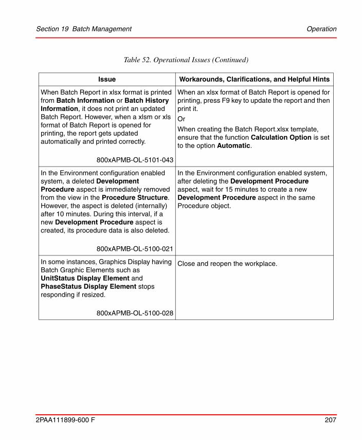
Section 19 Batch Management Operation
2PAA111899-600 F 207
When Batch Report in xlsx format is printed from Batch Information or Batch History Information, it does not print an updated Batch Report. However, when a xlsm or xls format of Batch Report is opened for printing, the report gets updated automatically and printed correctly.
800xAPMB-OL-5101-043
When an xlsx format of Batch Report is opened for printing, press F9 key to update the report and then print it.
Or
When creating the Batch Report.xlsx template, ensure that the function Calculation Option is set to the option Automatic.
In the Environment configuration enabled system, a deleted Development Procedure aspect is immediately removed from the view in the Procedure Structure. However, the aspect is deleted (internally) after 10 minutes. During this interval, if a new Development Procedure aspect is created, its procedure data is also deleted.
800xAPMB-OL-5100-021
In the Environment configuration enabled system, after deleting the Development Procedure aspect, wait for 15 minutes to create a new Development Procedure aspect in the same Procedure object.
In some instances, Graphics Display having Batch Graphic Elements such as UnitStatus Display Element and PhaseStatus Display Element stops responding if resized.
800xAPMB-OL-5100-028
Close and reopen the workplace.
Table 52. Operational Issues (Continued)
Issue Workarounds, Clarifications, and Helpful Hints

Operation Section 19 Batch Management
208 2PAA111899-600 F
While upgrading an existing system to the System Version 5.1/6.0, the system overwrites the entire Miscellaneous Configuration Aspect in the backup. This removes all the existing Batch IDs and the stored settings in the Miscellaneous Configuration Aspect.
In addition, some incorrect Batch IDs are also loaded as part of Miscellaneous Configuration. The incorrect Batch IDs will also appear in a newly created system.
800xAPMB-OL-5100-031
Restored system:
Export the Miscellaneous Configuration aspect from the [Library Structure]BatchManagement/Configuration object in the backed up system.
Import the Miscellaneous Configuration aspect, after restoring the system.
New system:
Identify the incorrect Batch IDs and remove them manually.
For Batch interfacing with DCI systems, Batch IDs having more than 20 characters cause a time-out condition to be generated by the Batch manager when trying to execute the procedure.
800xAPMB-OL-5100-032
Always ensure the Batch IDs have less than 21 characters.
Batch equipment and phase templates do not work after a Version 3.1 SP3 800xA System is restored on a Version 5.0 SP2 800xA System.
800xAPMB-OL-5020-028
1. Delete the MainFaceplate and/or MainFaceplate_Pre50 aspects from each phase type in all user libraries (Object Type Structure/ Object Type/AC800M/C Connect/Libraries/ user_library/Control Module Types/phase_types).
2. Copy the MainFaceplate aspect from Object Type Structure/Object Type/AC800M/C Connect/Libraries/BatchAdvTemplatesLib/Control Module Types/PhaseTemplate object to each phase type in all user libraries.
Table 52. Operational Issues (Continued)
Issue Workarounds, Clarifications, and Helpful Hints

Section 19 Batch Management Operation
2PAA111899-600 F 209
If Batch Equipment (Units) and Equipment Group objects are deleted from a system and then the same objects are imported back into the system (from an .afw file), procedures that reference these deleted objects will not execute properly. Control recipe execution failure modes will vary based upon the specific circumstances.
800xAPMB-OL-5000-026
If the Batch application has been installed in a redundant configuration and the secondary Batch server is active and synchronized, force a failover to secondary server node operation to allow the affected procedures to execute properly. The former primary Batch Server should then be restarted and established as the secondary Batch Server using the standard published instructions.
If the Batch application has been installed in a non-redundant configuration (or the secondary Batch server is not available), it is necessary to stop the Batch Services, shutdown and restart the Batch Server and restart Batch services to allow the affected procedures to execute properly.
Poor usage of memory by bmsAddValue results in the recipe editor running out of memory. This happens while recipe is saved with 3000 parameters.
800xAPMB-OL-5102-044
Allocate more memory to reduce reallocate frequency.
When attempting to schedule a Batch using batch_sbatch for a procedure that has the same name as another procedure, the following error will appear and the schedule call will fail:
Errors:
Specified recipe does not exist.
800xAPMB-CN-5024-010
To identify duplicate named procedures, the path to the procedure must be specified as mentioned in the following example:
batch_sbatch -b BID -r PathToProcedure/ProcedureName.
Table 52. Operational Issues (Continued)
Issue Workarounds, Clarifications, and Helpful Hints

Operation Section 19 Batch Management
210 2PAA111899-600 F
In the versions prior to 5.0, the “Event Attribute Object Extension” aspect is present in the Service Structure under the Alarm Manager. For version 5.0 and greater, these are not required. Leaving these entries in place will cause the Alarm Events data (report) to have redundant entries.
800xAPMB-OL-5102-047
These Event Attribute Object Extensions are no longer used for Alarm Management.
Delete all the "Event Attribute Object Extension" aspects.
Melody phase driver collects the output parameters in Completed and Aborted states only.
800xAPMB-OL-5104-089
No workaround exists for this issue.
In the Procedure Structure of PPA, system stops responding and may crash if reference to one of the Procedure Object is inserted under the same Object and is kept empty.
800xAPMB-OL-5130-094800xAPMB-OL-5104-091
Delete the lower Empty Procedures Object.
When creating a new equipment, the type defaults to AC 800M/C, which is counted towards the number of equipment(s). If the equipment count is already at its maximum, then the creation of a new equipment including Pseudo units is rejected.
800xAPMB-OL-6000-001
Copy and Paste an existing pseudo unit. If there are no pseudo units, then the workaround is to remove one of the real units, and add the pseudo unit, and then re-add the real unit.
Table 52. Operational Issues (Continued)
Issue Workarounds, Clarifications, and Helpful Hints

Section 19 Batch Management Operation
2PAA111899-600 F 211
In case of Failover of Batch Server, if the equipment overview window is open, then the updated status of the equipment is not shown.
800xAPMB-OL-6000-002
Close and reopen the equipment overview window to show the correct status of the equipment.
A non-redundant Batch server will fail to periodically truncate the transaction logs. The transaction logs will grow unbounded and eventually consume all the disk space.
800xAPMB-OL-6000-009
Perform a database backup of the SymFlexDB database. The periodic transaction log truncation will then succeed.
The Batch DSN Utility will not run properly when launched from the ABB Start Menu. User will get an error message
800xAPMB-OL-6000-010
No workaround exists for this issue.
Batch Manager stops responding if the License Status Viewer application is opened in the system for extended periods of time (greater than an hour).
800xAPMB-OL-6000-011
Avoid opening License Status Viewer application on Batch server nodes.
Table 52. Operational Issues (Continued)
Issue Workarounds, Clarifications, and Helpful Hints

Operation Section 19 Batch Management
212 2PAA111899-600 F

2PAA111899-600 F 213
Section 20 800xA History
Known ProblemsThis section details the Known Problems for the 800xA History that exist in the system at the time of release.
Fixed in 800xA 6.0
Installation
Table 52 lists the issues that may exist and affect installation of the system or product at time of release. Workarounds, clarifications, or helpful hints have been provided for each issue wherever possible.

Installation Section 20 800xA History
214 2PAA111899-600 F
Table 52 Installation Issues
Issue Workarounds, Clarifications, and Helpful Hints
During installation of HA History Servers in Workgroup environment, database installation gets skipped in Replica History Server.
800xAHistory-IN-6000-002
Before starting the installation of History Servers in HA Configuration, perform the below steps in both the History Servers.
1. Disable User Access Control from Control Panel > User Accounts > Change User Account Control settings.
2. Open the Local Security Policy for the Control Panel > Administrative Tools.
3. In the Local Security Policy window, navigate to Security Settings > Local Policies > Security Options.
4. Select the Security Policy named as User Account Control: Run all administrators in Admin Approval Mode and change the Security Setting from Enabled to Disabled.
5. Close the Local Security Policy window.
In the event of NLB network cable disconnection at the Primary History Server, holding the Master Token of Services, the Hot- Standby History Server does not take over the Master Tokens for EventForwarder and TagConsistencyController. Due to this, the newly created tags and the events does not get collected in either of History Servers.
800xHIS-IN-2001-002
Stop the History Services of the earlier Primary which was holding the Master Tokens.

Section 20 800xA History Configuration
2PAA111899-600 F 215
Configuration
Table 53 lists the issues that may exist and affect configuration of the system or product at time of release. Workarounds, clarifications, or helpful hints have been provided for each issue wherever possible.
Operation
Table 54 lists the issues that may exist and affect operation of the system or product at time of release. Workarounds, clarifications, or helpful hints have been provided for each issue wherever possible.
Table 53. Configuration Issues
Issue Workarounds, Clarifications, and Helpful Hints
Deadband configuration on Log Configuration aspect is not available.
800xAHistory-CN-2000-003
No workaround exists for this issue.
Table 54. Operational Issues
Issue Workarounds, Clarifications, and Helpful Hints
Status alarms of RTDB Services in Standby DCN does not get reported in 800xA System Alarm List.
800xAHistory-OL-2000-006
No workaround exists for this issue.

Operation Section 20 800xA History
216 2PAA111899-600 F
In HA Configuration of 800xA History Servers, if the Hot-Standby History Server is unavailable then the History Supervision aspect will not update the correct status of Replica Node.
800xAHIS-OL-6000-002
No workaround exists for this issue.
Event Retrieval into 800xA fail with Timeout popup when a single subcategory of events are tried to retrieve from History database. This happens only with unbounded timestamp queries (latest time to oldest time).
800xAHistory-OL-6000-003
Use bounded time queries (specific timestamps) to retrieve single subcategory of events.
Table 54. Operational Issues (Continued)
Issue Workarounds, Clarifications, and Helpful Hints

2PAA111899-600 F 217
Section 21 Information Management
Known ProblemsThis section details the Known Problems for Information Management that exist in the system at the time of release.
Configuration
Table 55 and Table 56 lists the issues that may exist and affect configuration of the system or product at time of release. Workarounds, clarifications, or helpful hints have been provided for each issue wherever possible.
Table 55. Configuration Issues
Issue Workarounds, Clarifications, and Helpful Hints
Data Direct XLA fails to load with the following error:
Microsoft Visual Basic
! Object library invalid or contains references to object definitions that could not be found.
800xAINM-CN-5103-036
Execute the following to remove old cached EXD files:
C:\ProgramData\ABB\IM\DataDirect\Bin\DeleteFilesAction.exe
This will find and delete all EXD files on the System Drive allowing the DataDirect XLA to load, the next time Excel is opened.

Operation Section 21 Information Management
218 2PAA111899-600 F
Operation
Table 56 lists the issues that may exist and affect operation of the system or product at time of release. Workarounds, clarifications, or helpful hints have been provided for each issue wherever possible.
After update or upgrade of system, configuration of Action Aspect and Scheduling Definition aspect is set to default values on AO Asset Condition History and AO Running Time Report Job description objects.
800xAINM-CN-5100-003
Restore the Action Aspect and Scheduling Definition aspect configuration manually on the Asset Condition History and AO Running Time Report Job description object.
It is difficult to recover an IM node when it is deleted from the system, because objects under the node object are not deleted.
800xAINM-CN-3600-0004
Object under the node object has to be deleted and recreated when the IM is added back into the system, including fixing the GUID for the PPA basic history.
When an Information Management server object is deleted from the Node Administration structure, the corresponding Inform IT History Objects are not deleted from the Node Administration structure.
800xAINM-CN-3500-0004
Delete the objects manually. They are located at the top of the Plant Explorer.
Table 55. Configuration Issues (Continued)
Issue Workarounds, Clarifications, and Helpful Hints

Section 21 Information Management Operation
2PAA111899-600 F 219
Table 56. Operational Issues
Issue Workarounds, Clarifications, and Helpful Hints
Desktop Trend files migrated from earlier versions of 800xA will not display properly in version 6.0 due to a compatibility problem with the newer version of Internet Explorer.
800xAINM-OL-6000-011
To resolve the issue a compatibility tag needs to be added to the saved Trend file.
1. Open the Desktop Trend HTML file with Notepad. The first few lines looks as follows:
2. Insert the following line of text between the <HEAD> and <TITLE> tags in the HTML file.
<META http-equiv="X-UA-Compatible" content="IE=EmulateIE8,requiresActiveX=true">
3. Save the HTML file and exit Notepad. The Desktop Trend file should now display properly.

Operation Section 21 Information Management
220 2PAA111899-600 F
Excel report templates that contain data bound tables connected to the Information Manager ODA ODBC connection have been seen to fail to properly update when the report is executed.
800xAINM-OL-6000-010
Two actions may be needed to resolve this issue. First review the connection string for the ODBC query. It is found on the Data ribbon, Connection Properties Dialog on the Refresh All drop-down, Definition tab.Verify the port number for ODBC connection is correct. It should be 28996. If the port number is correct or updating the port number does not correct the issue then uncheck Enable background refresh from Usage tab of the Connection Properties Dialog as well.
When attempting to launch IM ACC Setup from the ABB Batch PDL Extractor by clicking on the Localhost test, a runtime error 5 will be seen and the setup application will fail to launch.
800xAINM-OL-6000-007
To launch IM ACC Setup use the ABB Start Menu and launch the application which you will find under Information Mgmt>Utilities.
While installing Oracle the message OraProvCfg.exe has stopped working has been seen.
800xAINM-IN-6000-006
Acknowledge the message and the Oracle Installation will successfully run to completion.
It is not possible to open the on-line help file from the Display Services Client application.
800xAINM-OL-6000-001
To find any needed Display Services Client help please refer to the Information Management Display Services User Manual.
A Trend Display launched from the PDL Browser will not properly show data if the PDL Browser is configured with a time format of DD-MM-yy.
800xAINM-OL-6000-002
To avoid this issue, do not use the DD-MM-yy time format in the PDL Browser.
Table 56. Operational Issues (Continued)
Issue Workarounds, Clarifications, and Helpful Hints

Section 21 Information Management Operation
2PAA111899-600 F 221
Pressing the Cancel button on the A/E Linked Configuration Aspect does not restore the configuration of the aspect to the previously saved settings.
800xAINM-OL-6000-003
To restore the settings in the A/E Linked to those previously saved select a different aspect and then return to the A/E Linked Configuration Aspect. This will refresh the configuration information to show the stored configuration.
PPA will add a backslash "\" to escape certain characters in the filter string provided to the hsArchiveService. Specificaly, the "-" will be passed as "\-". The new code does not remove the escape character and this will prevent message from being returned.
800xAINM-OL-6000-004
There is no workaround for this issue
When the Display Services Client is launched for the first time for a given user a short series of installation dialogs will be shown. After the dialogs clear the application is launched properly and the installation dialogs will not be seen when the Display Services Client is launched in the future.
800xAINM-OL-6000-005
Allow the installation dialogs to complete. No further issues should be seen.
Table 56. Operational Issues (Continued)
Issue Workarounds, Clarifications, and Helpful Hints

Operation Section 21 Information Management
222 2PAA111899-600 F
The DataDirect menu is sometimes missing in Office 2013.
800xAINM-OL-5104-043
Follow the steps below to fix this issue. The procedure must be executed for each user that encounters this problem.
1. Open Excel.
2. Click the Add-ins tab.
3. Click the Options button of DataDirect to open
Options window.
4. Go to View tab and change any of the options there and then click OK. The DataDirect menu will now be shown. The problem will not happen again for this user.
Scheduler Data Collection Actions will fail, with an error message Failed to Activate Log Number(s), if any of the logs in the Log List are from an AC400 controller and contain a period (".") in the log name.
800xAINM-OL-5104-041
There is no workaround for this issue.
Excel may crash on exit after viewing a report that was launched from the File Viewer aspect. Dismiss the Excel error dialog to close Excel. This condition does not cause any data loss or corruption.
800xAINM-OL-5100-001
There is no workaround for this issue.
Table 56. Operational Issues (Continued)
Issue Workarounds, Clarifications, and Helpful Hints

Section 21 Information Management Operation
2PAA111899-600 F 223
Scheduled reports may appear to fail when using the Save to History option with the following error: Job Action: Action Aspect, Completed (failure), Error while running automation type EX: Method'~' of object '~' failed
This error is occasionally seen only on reports that have been configured with the Save to History output option enabled. Inspite of the error message, the output file will still be correctly written to the history log. However, if the report is also configured to be exported to an 800xA Object (in addition to the Save to History output option) the report will not be written to the Completed Report Object when the error occurs.
800xAINM-OL-5100-002
If reports are configured to only store to History, then no action is required - the reports are still being stored properly.
If storing completed reports to History is not required, the issue can be avoided by clearing the Save to History output option. In cases where both Save to History and Export to an Object Path options are necessary, reports are not written properly to the Completed Report Object, but can still be viewed through the History log.
Failed reports can also be re-run manually.
Alarms and Events from both the provider system (multisystem integration functionality) appear in the 800xA Alarm and Event list, however only the alarms are recorded by the DataDirect function within Information Management.
800xAINM-OL-5010-061
There is no workaround for this issue.
Table 56. Operational Issues (Continued)
Issue Workarounds, Clarifications, and Helpful Hints

Operation Section 21 Information Management
224 2PAA111899-600 F
A batch report scheduled to be run at the completion of a batch may miss data intended for the report.
800xAINM-OL-5020-043
If a batch report is intended to be automatically scheduled by the Batch Manager to include all data associated with a batch, include a delay block in the batch recipe just prior to the end of the recipe. The delay should include enough time (approximately 90 seconds) to ensure all data is available for reporting.
Reports executed manually will contain all data.
The time offset feature of the Desktop Trend has been observed to cause the trace to disappear.
800xAINM-OL-5020-041
To obtain similar results, instead of using the time offset feature, modify the traces vertically by adjusting the range value of the Y-axis.
Table 56. Operational Issues (Continued)
Issue Workarounds, Clarifications, and Helpful Hints

Section 21 Information Management Operation
2PAA111899-600 F 225
When using the Store Original Value feature of Information Management history logs type 5 (numeric), the original status is not stored when the value is modified.
800xAINM-OL-5020-018
History logs of type 1 should be used if the ability to save the original status when the status value is modified is desired.
AID client (Display Services) displays, sometimes use incorrect fonts. Due to a change in Windows functionality, AID client displays, now uses font information from registry keys instead of the aidfonts.ini file.
800xAINM-OL-4100-0036
Add the HKEY_CURRENT_USER\ SOFTWARE\ABB\AID\Fonts\FaceName_ 0, ...\FaceName_1, and ...\FaceName_2 keys to the registry. Use the value names and values listed below for all three keys:
Value Name (Default) Font
Name Ariel
BaseSize_0 11
BaseSize_1 14
BaseSize_2 17
BaseSize_3 18
BaseSize_4 23
BaseSize_5 33
Table 56. Operational Issues (Continued)
Issue Workarounds, Clarifications, and Helpful Hints

Operation Section 21 Information Management
226 2PAA111899-600 F

2PAA111899-600 F 227
Section 22 800xA for Advant Master
Known ProblemsThis section details the Known Problems for 800xA for Advant Master that exist in the system at the time of release.
Configuration
Table 57 lists the issues that may exist and affect the configuration of the system or product at time of release. Workarounds, clarifications, or helpful hints have been provided for each issue wherever possible.

Configuration Section 22 800xA for Advant Master
228 2PAA111899-600 F
Table 57. Configuration Issues
Issue Workarounds, Clarifications and Helpful Hints
The function Advant Master Alarm Refresh cannot be started manually, if more than one aspect with the name “General Properties” is placed on the Controller node object in the Control Structure. The property FORCE_REFRESH, which is used for manual refresh of the alarms, will not be found.
800xAADM-CN-6000-001
Do not create new aspects named “General Properties” on the controller node objects, if function Advant Master Alarm Refresh is enabled. Use the already predefined “General Properties” aspect and add the additional needed properties.
Node objects in Control structure of type MP200 Controller will report the following error:
"Formal aspect 'Control Connection' should not be propagated to instance...”
when running the Consistency checker tool after upgrade from older versions to 6.0.
800xAADM-CN-6000-002
The error can be repaired by the Consistency checker tool.

Section 22 800xA for Advant Master Operation
2PAA111899-600 F 229
Operation
Table 58 lists the issues that may exist and affect the operation of the system or product at time of release. Workarounds, clarifications, or helpful hints have been provided for each issue wherever possible.
Object has wrong type in control structure in System 800xA after upload. The issue is created by following this sequence:
1. Create a DI object in the controller
2. Upload the controller
3. Delete the DI object
4. Create an AI object with the same name as the deleted DI object
5. Upload the controller
800xAADM-CN-5102-001
Do the following to ensure that the correct object instance is added to the control structure in System 800xA:
1. Create a DI object in the controller
2. Upload the controller
3. Delete the DI object
4. Upload the controller, to ensure that the DI object is removed from the control structure
4. Create an AI object with the same name as the deleted DI object
5. Upload the controller to add the correct object instance to the control structure
The online help for On-line Builder Commands do not function for RTA board Configuration in Windows 8.1 and Windows Server 2012 R2.
800xAADM-CN-5100-004
A Windows Help and Support window is displayed if any error occurs.
It is possible to correct the error for Windows 8.1 by following the instructions provided in Microsoft Help and Support website. This instruction includes download of a program that helps to view the On-line Builder Commands help file.
Table 57. Configuration Issues (Continued)
Issue Workarounds, Clarifications and Helpful Hints

Operation Section 22 800xA for Advant Master
230 2PAA111899-600 F
Table 58. Operational Issues
Issue Workarounds, Clarifications and Helpful Hints
The Local device status display used for AC 410, AC 450 and Safeguard controllers may indicate wrong status for the second Program/Application card.
800xAADM-OL-5111-002
No workaround exists for this issue.
The following MMCX-base object types do not support Alarm Refresh:
• MB300 Engineered drive
• MB300 Standard drive
• MB300 MMCX1
• MB300 MMCX2
• MB300 MMCX3
• MB300 MotconI
800xAADM-OL-5111-003
To get latest alarm status in the alarm list after a communication failure with the controller:
Open the faceplates for all instance of these object types. If object indicates alarm state, toggle the Alarm Block button twice.This will update the alarm list.
Quick list can be used to search for MB300 MMCX1, MB300 MMCX2 and MB300 MMCX3 objects in alarm state.
The following Process Graphics displays can cause a crash in the OPCDA service:
• AC Local Devices:Local devices,
• AC Local Devices:Net Status 1,
• AC Local Devices:Net Status 2
• MB300 Group Alarm: Object Display.
Also other custom displays and clients subscribing on the properties of type VT_ARRAY of these objects are affected.
800xAADM-OL-5111-005
Avoid using the mentioned 800xA for Advant Master Process Graphics displays, and do not use array properties (type VT_ARRAY) in 800xA for Advant Master Process Graphics displays.
A crash will leave a distinct error message containing both "AdvDsOPCConnector.exe caused an EXCEPTION_ACCESS_VIOLATION" and the word "SAFEARRAY" embedded in the call stack text. The exception log file can be found on either of the following two paths:
• C:\ProgramData\ABB\Process Portal A\Log\Exception_Crash_Handler_AdvDsOPCConnector.log
• \OperateITTemp\log\Exception_computername.log

Section 22 800xA for Advant Master Operation
2PAA111899-600 F 231
Misleading information appears in display elements when opening a process display, if the controller is in configuration mode.
800xAADM-OL-5100-008
Some display elements show a valid symbol for a minute, even if the related controller is stopped. For example, a valve symbol shows Closed position. After sometime, the display elements indicate bad data.
Process objects may in rare situations be locked for operation for a period of 5 minutes. The problem seem to be related to situations where the controller is stressed into high load, resulting in a too long response time. The faceplate view indicates 'locked by other', but there are no other users of the object.
800xAADM-OL-5010-005
No workaround exist for this issue.
Some alarms cannot be acknowledged after restart of Connectivity Server.
800xAADM-OL-5103-001
No workaround exist for this issue.
These alarms can however be acknowledged when the object is in normal state and no other unacknowledged alarms exist in the alarm list for this object.
Alarms generated first few seconds after a controller restart may not be sent to a Connectivity Server, due to late reaction in the Connectivity Server when the controller becomes available again.
800xAADM-OL-5103-002
No workaround exist for this issue.
Table 58. Operational Issues (Continued)
Issue Workarounds, Clarifications and Helpful Hints

Operation Section 22 800xA for Advant Master
232 2PAA111899-600 F

2PAA111899-600 F 233
Section 23 800xA for AC 100
Known ProblemsThis section details the Known Problems for 800xA for AC 100 (including AC 100 OPC Server) that exist in the system at the time of release.
Configuration
Table 59 lists the issues that may exist and affect configuration of the system or product at time of release. Workarounds, clarifications, or helpful hints have been provided for each issue wherever possible.
Table 59. Configuration Issues
Issue Workarounds, Clarifications, and
Helpful Hints
800xA for AC 100 does not support disabling of alarms from alarm list. There is no way to enable alarms which have been disabled.
Performing “Disable Object” from context menu for an alarm condition will disable alarms from that object until the Connectivity Server is restarted.
800xAAC1-CN-5020-002
To disable the function uncheck the “Supports Disabling” check box, in the ABB AC 100 OPC Alarm Server, Alarm Collector Definition object in Library Structure.
No NLS support exists for the Event Categories (Process Condition Event, System Condition Event and System Simple Event) and Event Conditions (Level L, Level LL, etc.)
800xAAC1-CN-3100-001
No workaround exists for this issue.

Configuration Section 23 800xA for AC 100
234 2PAA111899-600 F
Alarm limits of DAT_AI are not visible in OPC and hence in PPA.
800xAAC1-CN-5020-001
Use the AIS element instead of DAT_AI, if alarm limits are needed.
Table 59. Configuration Issues (Continued)
Issue Workarounds, Clarifications, and
Helpful Hints

Section 23 800xA for AC 100 Operation
2PAA111899-600 F 235
Operation
Table 60 lists the issues that may exist and affect operation of the system or product at time of release. Workarounds, clarifications, or helpful hints have been provided for each issue wherever possible.
Table 60. Operational Issues
Issue Workarounds, Clarifications, and Helpful Hints
The faceplate Alarm Control does not indicate that the alarm is blocked if the alarm is in alarm state.
800xAAC1-OL-5100-001
No workaround exists for this issue.
CI527A must be set to AF 100 Bus Master to get proper status indication for System Status Viewer.
800xAAC1-OL-6000-001
Always configure CI527A as AF 100 Bus Master.
It is not possible to enter values using the Input field, outside the range 0-100 on the following faceplates: AIS, AOS, DAT_AI and MR. However, entering values from the bar graph is possible.
800xAAC1-OL-4100-001
The faceplate elements Control PG2 and Reduced Control PG2 can be corrected for these object types. The Max/ Min parameters should be set to RANGE_MAX/RANGE_MIN instead of 100/0.
The DAT_DAT faceplate cannot present boolean values, and it is not possible to enter a new value for any value type.
800xAAC1-OL-5020-002
No workaround exists for this issue.

Operation Section 23 800xA for AC 100
236 2PAA111899-600 F
If an alarm for DAT_AI is active in the Advant Controller and was send to OPC Server, after a restart of the OPC Server, the Alarm is not delivered to OPC Clients.
800xAAC1-OL-3100-001
If the alarm later on becomes inactive this is not shown in the alarm list.
A single cable failure on AF100 leads to toggling of Status bit for AC 100 AF100 CI and therefore also AC 100 AF100 CI Summary.
800xAAC1-OL-4000-001
No workaround exists for this issue.
Removing one AF100 interface of a redundant pair is not signalled in AC 100 AF100 CI Status object.
800xAAC1-OL-4000-002
Missing module errors are indicated by the AC 100 AF100 IO CI Summary object.
The Faceplate aspect for signal objects, that can have a value above ten million, does not show the correct value when it exceeds ten million.
800xAAC1-OL-5020-001
Customize faceplate and Object Display.
Table 60. Operational Issues (Continued)
Issue Workarounds, Clarifications, and Helpful Hints

2PAA111899-600 F 237
Section 24 800xA for Safeguard
Known ProblemsThis section details the Known Problems for 800xA for Safeguard that exist in the system at the time of release. It also enumerates known problems encountered in the final testing of this product release and identifies workarounds that help overcome the problem.
Operation
Table 61 lists the issues that may exist and affect operational of the system or product at time of release. Workarounds, clarifications, or helpful hints have been provided for each issue wherever possible.
Table 61. Operational Issues
Issue Workarounds, Clarifications and Helpful Hints
Double-click an Advant Master graphic element. This might display an Object Display instead of the Faceplate.
800xAADM-OL-4100-015
Execute the following steps:
1) Open the Aspect Precedence List aspect located in the Library Structure (Library Structure > Preferences & Customizations > Aspect Precedence Lists > Default precedence list).
2) Move the Default Aspect below the Faceplate.

Operation Section 24 800xA for Safeguard
238 2PAA111899-600 F

2PAA111899-600 F 239
Section 25 800xA for AC 870P/Melody
Known ProblemsThis section details the Known Problems for the 800xA for AC 870P/Melody that exist in the system at the time of release. It also enumerates known problems encountered in the final testing of this product release and identifies workarounds that help overcome the problem.
Installation
Table 62 lists issues that may exist and affect the installation and upgrade of the system or product at time of release. Workarounds, clarifications, or helpful hints have been provided for each issue wherever possible.
Table 62. Installation Issues
Issue Workarounds, Clarifications, and Helpful Hints
Unable to open the Object List in Melody Configuration Server.
800xAMel-IN-6000-002
The prerequisite for the Object List to open is to set the language for Internet Explorer as English (United States) and this must be on top of all the preferred languages.
To set this: Open Internet Explorer >Options > Languages >Set Language Preferences.

Operation Section 25 800xA for AC 870P/Melody
240 2PAA111899-600 F
Operation
Table 63 lists the issues that may exist and affect operation of the system or product at time of release. Workarounds, clarifications, or helpful hints have been provided for each issue wherever possible.
The following functionalities are currently unavailable within System 800xA 6.0:
• System 800xA for Melody Asset Management for HART Devices.
• Composer Melody Navigation.
These functionalities require a Composer Melody (S+ Engineering) installation on 800xA Nodes.
There is currently no release of Composer Melody on Windows 8.1 and Windows Server 2012 R2.
800xAMel-IN-6000-003
Users who need these functionalities, should contact ABB Level 3 Support for further information.
Table 63. Operational Issues
Issue Workarounds, Clarifications, and Helpful Hints
If a Trend Display is open, it could possibly be that the low and high range for some tags did not show the actual value instead showed the default range 0 - 100.
800xAMel-OL-6000-001
Reopening the Trend Display can fix this issue.
Table 62. Installation Issues (Continued)
Issue Workarounds, Clarifications, and Helpful Hints

2PAA111899-600 F 241
Section 26 800xA for DCI
This section details the Known Problems for the 800xA for DCI that exist in the system at the time of release.
Installation
Table 64 lists issues that may exist and affect the installation and upgrade of the system or product at time of release. Workarounds, clarifications, or helpful hints have been provided for each issue wherever possible.
Table 64. Installation Issues
Issue Workarounds, Clarifications, and Helpful Hints
If the system is configured with 800xA Batch for DCI and the System Update Tool is used to update to 800xA 5.1 current revision, in 800xA for DCI when DCI MSET objects are created or imported an error message appears due to an outdated aspect "MSET Type Definition.
The 40_DciBatchObjectTypes.afw file must be re-imported before uploading any DCI MSET objects.
800xADCI-IN-5101-002
Execute the following steps:
1. Open the Import/Export Tool from Start > All Programs > ABB Industrial IT 800xA > System > Import Export.
2. Click the Open icon or select File > Open, to open the 40_DciBatchObjectTypes.afw file.
Path:
C:\ Program Files (x86)\ ABB Industrial IT\800xA\ DCI Library\ DciBatch\ import\40_DciBatchObjectTypes.afw
3. Click the Import All icon or select Actions > Import All, and then click Finish.
Click Yes on the prompts on overwriting aspects.

Installation Section 26 800xA for DCI
242 2PAA111899-600 F
Replacing an 800xA for DCI Connectivity Server using the System Configuration Console after that node had been previously deployed successfully will result in a failed action on creating a service provider.
800xADCI-IN-6000-003
Delete the OPC DA and Event Collector Service Providers that were created during the original node deploy before deploying a replaced node.
The OPC DA Service Providers are located in Service Structure->OpcDA_Connector->[GroupName]->[ProviderName].
The Event Collector Service Providers are located in Service Structure->Event Collector->[GroupName]->[ProviderName].
Where [GroupName] and [ProviderName] are the Service Group and Service Provider names for the node being replaced.
Table 64. Installation Issues (Continued)
Issue Workarounds, Clarifications, and Helpful Hints
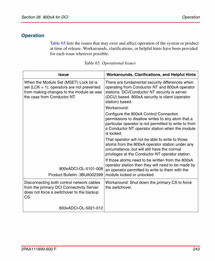
Section 26 800xA for DCI Operation
2PAA111899-600 F 243
Operation
Table 65 lists the issues that may exist and affect operation of the system or product at time of release. Workarounds, clarifications, or helpful hints have been provided for each issue wherever possible.
Table 65. Operational Issues
Issue Workarounds, Clarifications, and Helpful Hints
When the Module Set (MSET) Lock bit is set (LCK = 1), operators are not prevented from making changes to the module as was the case from Conductor NT.
800xADCI-OL-5101-008
Product Bulletin: 3BUA002399
There are fundamental security differences when operating from Conductor NT and 800xA operator stations. DCI/Conductor NT security is server (DCU) based. 800xA security is client (operator station) based.
Workaround:
Configure the 800xA Control Connection permissions to disallow writes to any atom that a particular operator is not permitted to write to from a Conductor NT operator station when the module is locked.
That operator will not be able to write to those atoms from the 800xA operator station under any circumstance, but will still have the normal privileges at the Conductor NT operator station.
If those atoms need to be written from the 800xA operator station then they will need to be made by an operator permitted to write to them with the module locked or unlocked.
Disconnecting both control network cables from the primary DCI Connectivity Server does not force a switchover to the backup CS.
800xADCI-OL-5021-012
Workaround: Shut down the primary CS to force the switchover.
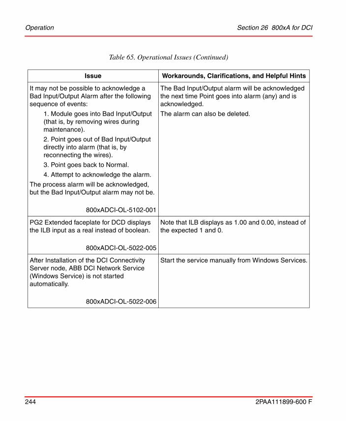
Operation Section 26 800xA for DCI
244 2PAA111899-600 F
It may not be possible to acknowledge a Bad Input/Output Alarm after the following sequence of events:
1. Module goes into Bad Input/Output (that is, by removing wires during maintenance).
2. Point goes out of Bad Input/Output directly into alarm (that is, by reconnecting the wires).
3. Point goes back to Normal.
4. Attempt to acknowledge the alarm.
The process alarm will be acknowledged, but the Bad Input/Output alarm may not be.
800xADCI-OL-5102-001
The Bad Input/Output alarm will be acknowledged the next time Point goes into alarm (any) and is acknowledged.
The alarm can also be deleted.
PG2 Extended faceplate for DCD displays the ILB input as a real instead of boolean.
800xADCI-OL-5022-005
Note that ILB displays as 1.00 and 0.00, instead of the expected 1 and 0.
After Installation of the DCI Connectivity Server node, ABB DCI Network Service (Windows Service) is not started automatically.
800xADCI-OL-5022-006
Start the service manually from Windows Services.
Table 65. Operational Issues (Continued)
Issue Workarounds, Clarifications, and Helpful Hints

Section 26 800xA for DCI Operation
2PAA111899-600 F 245
Scheduled Batch fails with an error during DCI Connect Redundancy Switchover.
800xADCI-OL-5020-028
To tell if a phase is currently active, examine the MSEQ module (hierarchically directly under the MSET module). The faceplate provides the state of the current phase, if any. In addition, the CCL display will show where the phase is currently executing. If a Phase is selected, but the Run command has not been issued, the selected phase will show in yellow on the PHS line. When the phase is still running, the MSEQ faceplate will show this and the CCL display will show the executing statements.
If the Phase has been selected, but not run, restart the phase. If the phase is currently running, allow it to complete and then skip the phase. If no phase is selected, determine from the process if the phase has completed, and, if it has, skip the phase. Otherwise, restart the phase.
On DCI TMR Faceplates, the FMT value cannot be edited in the Normal Faceplate display.
800xADCI-OL-5022-008
Enter SP changes on the Extended Faceplate Display Limits tab in the SPL field. Enter the desired time as seconds.
On a restart of a Connectivity Server, the Connectivity Server may not list all nodes it finds as introduced.
800xADCI-OL-5023-010
Dual Watchdog completes its startup with the event %+ communication with DCI network resumed. This appears to be the last message recorded from that server during a startup. It may happen before all nodes are discovered.
System alarms that happen more than once are not displayed more than once in the alarm and event list.
800xADCI-OL-5023-009
This is as per design. System 800xA does not re-display alarms that have the same information as another active alarm. The Conductor NT Event Historian would display these alarms.
Table 65. Operational Issues (Continued)
Issue Workarounds, Clarifications, and Helpful Hints

Operation Section 26 800xA for DCI
246 2PAA111899-600 F
Opening a CCL window from a multiple screen workplace may open on a different screen than the screen where CCL window was called. If multiple CCL windows are open, it is difficult to know which CCL window belongs to which faceplate.
800xADCI-OL-5102-002
Open one CCL window at a time.
DCI Batch OPC server may stop reporting phase completions. The next phase cannot run because the MSEQ module associated with the phase is marked as in use.
800xADCI-OL-6000-001
Failing over to a redundant DCI Batch OPC Server frees the MSEQ module allowing the batch to continue.
DCI Batch sequences may show error as Sequence not IDLE. This has been observed in batches with parallel sequences.
800xADCI-OL-6000-002
There are no known workarounds.
Table 65. Operational Issues (Continued)
Issue Workarounds, Clarifications, and Helpful Hints
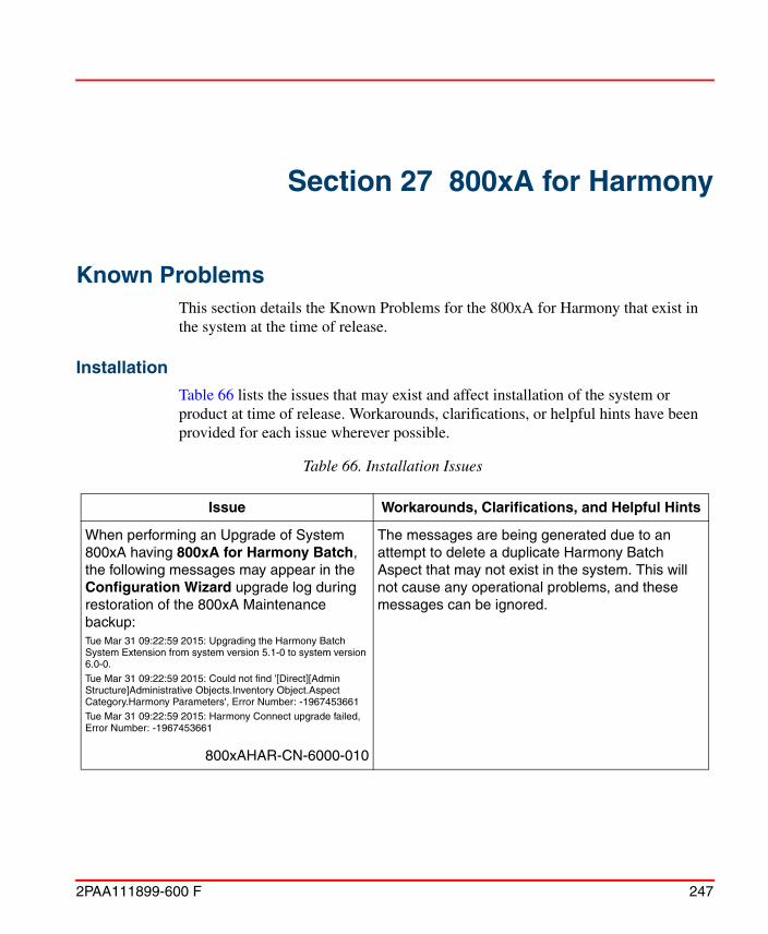
2PAA111899-600 F 247
Section 27 800xA for Harmony
Known ProblemsThis section details the Known Problems for the 800xA for Harmony that exist in the system at the time of release.
Installation
Table 66 lists the issues that may exist and affect installation of the system or product at time of release. Workarounds, clarifications, or helpful hints have been provided for each issue wherever possible.
Table 66. Installation Issues
Issue Workarounds, Clarifications, and Helpful Hints
When performing an Upgrade of System 800xA having 800xA for Harmony Batch, the following messages may appear in the Configuration Wizard upgrade log during restoration of the 800xA Maintenance backup:Tue Mar 31 09:22:59 2015: Upgrading the Harmony Batch System Extension from system version 5.1-0 to system version 6.0-0.Tue Mar 31 09:22:59 2015: Could not find '[Direct][Admin Structure]Administrative Objects.Inventory Object.Aspect Category.Harmony Parameters', Error Number: -1967453661Tue Mar 31 09:22:59 2015: Harmony Connect upgrade failed, Error Number: -1967453661
800xAHAR-CN-6000-010
The messages are being generated due to an attempt to delete a duplicate Harmony Batch Aspect that may not exist in the system. This will not cause any operational problems, and these messages can be ignored.

Installation Section 27 800xA for Harmony
248 2PAA111899-600 F
800xA for Harmony no longer supports SCSI INICI03 or later interfaces.
800xAHAR-IN-5101-004
800xA for Harmony supports IET800, PNI800, and serial interfaces.
The Make Redundant feature in the Nodes Configuration tab of the Configure Systems task, does not include the "PC, Network and Software Monitoring Services for Harmony and Melody" function in the list of available node functions that are redundant. 800xA for Harmony requires that the "PC, Network and Software Monitoring Services for Harmony and Melody" function be applied to all 800xA for Harmony Connectivity Server nodes.
800xAHAR-IN-6000-008
In the Node Configuration tab of the Configure Systems task, select each 800xA for Harmony Connectivity Server node and add the "PC, Network and Software Monitoring Services for Harmony and Melody" function. This needs to be done on every 800xA for Harmony Connectivity Server node in the system.
Replacing an 800xA for Harmony Connectivity Server using the System Configuration Console after that node had been previously deployed successfully, will result in a failed action on creating a service provider.
800xAHAR-IN-6000-009
Delete the Harmony Executive and Event Collector Service Providers that were created during the original node deploy before deploying a replaced node.
The Harmony Executive Service Providers are located in Service Structure->Harmony Executive->Basic->[ProviderName].
The Event Collector Service Providers are located in Service Structure->Event Collector->[GroupName]->[ProviderName].
Where [GroupName] and [ProviderName] are the Service Group and Service Provider names for the node being replaced.
Table 66. Installation Issues (Continued)
Issue Workarounds, Clarifications, and Helpful Hints
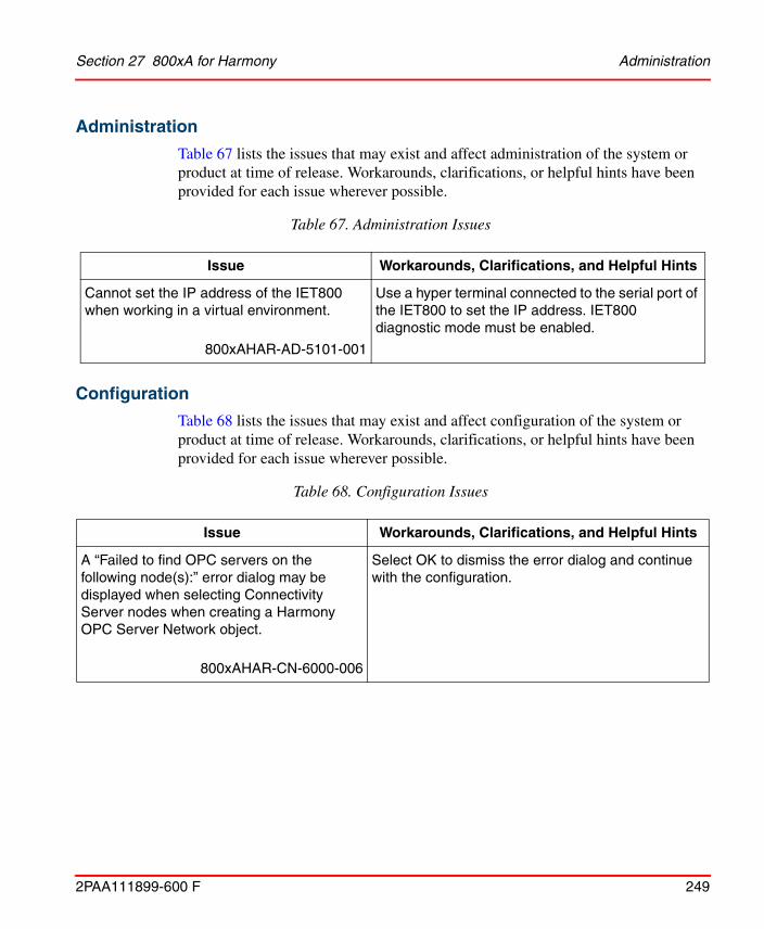
Section 27 800xA for Harmony Administration
2PAA111899-600 F 249
Administration
Table 67 lists the issues that may exist and affect administration of the system or product at time of release. Workarounds, clarifications, or helpful hints have been provided for each issue wherever possible.
Configuration
Table 68 lists the issues that may exist and affect configuration of the system or product at time of release. Workarounds, clarifications, or helpful hints have been provided for each issue wherever possible.
Table 67. Administration Issues
Issue Workarounds, Clarifications, and Helpful Hints
Cannot set the IP address of the IET800 when working in a virtual environment.
800xAHAR-AD-5101-001
Use a hyper terminal connected to the serial port of the IET800 to set the IP address. IET800 diagnostic mode must be enabled.
Table 68. Configuration Issues
Issue Workarounds, Clarifications, and Helpful Hints
A “Failed to find OPC servers on the following node(s):” error dialog may be displayed when selecting Connectivity Server nodes when creating a Harmony OPC Server Network object.
800xAHAR-CN-6000-006
Select OK to dismiss the error dialog and continue with the configuration.

Configuration Section 27 800xA for Harmony
250 2PAA111899-600 F
The OPCDA Service provider(s) that are created when a Harmony OPC Server Network object is created may not be enabled by default.
800xAHAR-CN-6000-007
In Plant Explorer, open the OPC DA Service Providers created for the Harmony Servers and verify that the Enabled checkbox is selected. If it is not, then select it and click on Apply.
The Service Providers are located under Service Structure->Services->OpcDA_Connector->SG_name of Harmony OPC Server Network object
When exporting/importing PG2 graphic displays from one Harmony system to the other, there is no Display Tool available to fix object references.
800xAHAR-CN-5021-006
To transfer PG2 aspects and resolve and approve them on a different system:
• Import the PG2 graphic displays.
- Aspect by aspect - Data References > Resolve All > OK > Save, Close.
- Partial Multiple aspects - Use the Check Consistency Tool > Select All > Repair > All aspects will be Unapproved. Drag each object/aspect into the Reference Tool > Approve.
If a user attempts to re-import tags on a system that has been upgraded, new Functional Structure assignments will not be imported if the “Merge…” option is selected.
If the “Replace…” option is selected, old Functional Structure assignments will be deleted, but the new assignments will not be imported.
A similar problem exists if importing the same tags a second time, but from a different .mdb file that contains Area, Unit, Equipment or SecGroup objects that have different object IDs than the original ones.
800xAHAR-CN-6000-003
Manually delete the target Functional Structure nodes (e.g. Area, Unit, Equipment, SecGroup objects) and re-import the .mdb file.
Table 68. Configuration Issues (Continued)
Issue Workarounds, Clarifications, and Helpful Hints

Section 27 800xA for Harmony Operation
2PAA111899-600 F 251
Operation
Table 69 lists the issues that may exist and affect operation of the system or product at time of release. Workarounds, clarifications, or helpful hints have been provided for each issue wherever possible.
Table 69. Operational Issues
Issue Workarounds, Clarifications, and Helpful Hints
Block and Module Detail display call-up times can be between 5 and 30 seconds when using an IET800 or PNI800 with 800xA for Harmony.
800xAHAR-OL-5101-003
No workaround exists for this issue. The call-up time for the Block and Module Detail display does not impact normal plant operation and control.
After fail-over of redundant 800xA for Harmony Connectivity Servers, the 'Active Times' of existing Harmony alarms can change.
800xAHAR-OL-5022-029
It is not possible to totally avoid this issue, however enabling Module Time Stamping on the Harmony Connectivity Servers will help to minimize the Active Time differences after a fail-over.
After fail-over of redundant 800xA for Harmony Connectivity Servers, Module Status Tag alarms that had been previously acknowledged may appear again as unacknowledged.
800xAHAR-OL-5102-014
No workaround exists for this issue.
The Harmony Module Status Tag Aspects that display Module Type incorrectly identify the SPIEB800 INFI-Net to PNI800 Plant Network Bridge module as an IIT05.
800xAHAR-OL-6000-004
No workaround exists for this issue.

Operation Section 27 800xA for Harmony
252 2PAA111899-600 F
Incorrect violated limits can be displayed for DAANG Tags with multiple level alarm limits defined.
800xAHAR-OL-5202-015
The software has been updated to improve the accuracy of the displayed DAANG Tag violated limits, however it is still possible that incorrect violated limits may be displayed.
The Enhanced Analog Input, Enhanced Analog Output, Enhanced Digital Input and Enhanced Digital Output, Enhanced Override Lock Status Faceplate Icon functionality is reversed. The keylock icon is displayed when the override lock status is false, and it is not displayed when the override lock status is true.
800xAHAR-OL-6000-005
No workaround exists for this issue.
Table 69. Operational Issues (Continued)
Issue Workarounds, Clarifications, and Helpful Hints
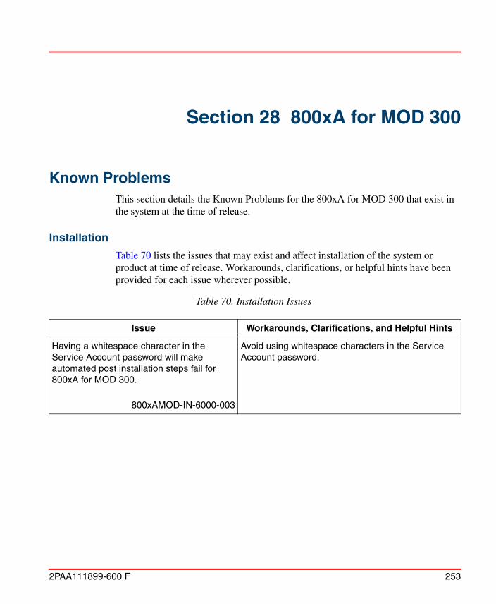
2PAA111899-600 F 253
Section 28 800xA for MOD 300
Known ProblemsThis section details the Known Problems for the 800xA for MOD 300 that exist in the system at the time of release.
Installation
Table 70 lists the issues that may exist and affect installation of the system or product at time of release. Workarounds, clarifications, or helpful hints have been provided for each issue wherever possible.
Table 70. Installation Issues
Issue Workarounds, Clarifications, and Helpful Hints
Having a whitespace character in the Service Account password will make automated post installation steps fail for 800xA for MOD 300.
800xAMOD-IN-6000-003
Avoid using whitespace characters in the Service Account password.
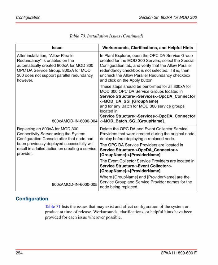
Configuration Section 28 800xA for MOD 300
254 2PAA111899-600 F
Configuration
Table 71 lists the issues that may exist and affect configuration of the system or product at time of release. Workarounds, clarifications, or helpful hints have been provided for each issue wherever possible.
After installation, "Allow Parallel Redundancy" is enabled on the automatically created 800xA for MOD 300 OPC DA Service Group. 800xA for MOD 300 does not support parallel redundancy, however.
800xAMOD-IN-6000-004
In Plant Explorer, open the OPC DA Service Group created for the MOD 300 Servers, select the Special Configuration tab, and verify that the Allow Parallel redundancy checkbox is not selected. If it is, then uncheck the Allow Parallel Redundancy checkbox and click on the Apply button.
These steps should be performed for all 800xA for MOD 300 OPC DA Service Groups located in Service Structure->Services->OpcDA_Connector->MOD_DA_SG_[GroupName]and for any Batch for MOD 300 service groups located in Service Structure->Services->OpcDA_Connector->MOD_Batch_SG_[GroupName].
Replacing an 800xA for MOD 300 Connectivity Server using the System Configuration Console after that node had been previously deployed successfully will result in a failed action on creating a service provider.
800xAMOD-IN-6000-005
Delete the OPC DA and Event Collector Service Providers that were created during the original node deploy before deploying a replaced node.
The OPC DA Service Providers are located in Service Structure->OpcDA_Connector->[GroupName]->[ProviderName].
The Event Collector Service Providers are located in Service Structure->Event Collector->[GroupName]->[ProviderName].
Where [GroupName] and [ProviderName] are the Service Group and Service Provider names for the node being replaced.
Table 70. Installation Issues (Continued)
Issue Workarounds, Clarifications, and Helpful Hints
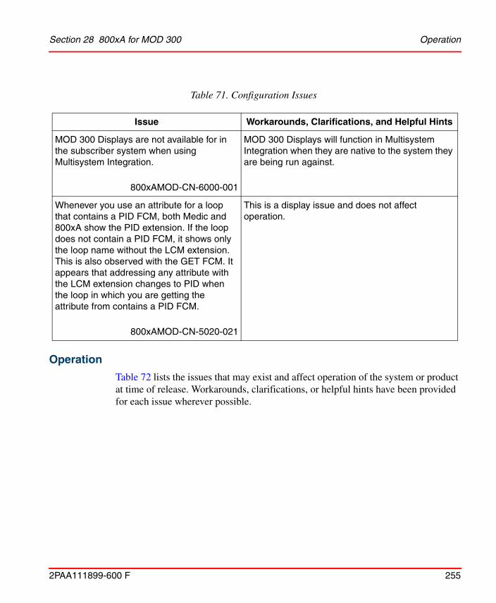
Section 28 800xA for MOD 300 Operation
2PAA111899-600 F 255
Operation
Table 72 lists the issues that may exist and affect operation of the system or product at time of release. Workarounds, clarifications, or helpful hints have been provided for each issue wherever possible.
Table 71. Configuration Issues
Issue Workarounds, Clarifications, and Helpful Hints
MOD 300 Displays are not available for in the subscriber system when using Multisystem Integration.
800xAMOD-CN-6000-001
MOD 300 Displays will function in Multisystem Integration when they are native to the system they are being run against.
Whenever you use an attribute for a loop that contains a PID FCM, both Medic and 800xA show the PID extension. If the loop does not contain a PID FCM, it shows only the loop name without the LCM extension. This is also observed with the GET FCM. It appears that addressing any attribute with the LCM extension changes to PID when the loop in which you are getting the attribute from contains a PID FCM.
800xAMOD-CN-5020-021
This is a display issue and does not affect operation.

Operation Section 28 800xA for MOD 300
256 2PAA111899-600 F
Table 72. Operational Issues
Issue Workarounds, Clarifications, and Helpful Hints
Any translation of a device loop INITIAL COMMAND field that represents a device descriptor set with binary output range greater than 15 will not display correctly in Loop FCMs.
800xAMOD-OL-5103-001Product Bulletin 3BUA002812
There is no workaround for this issue.
Messages appear to be lost from TCL programs.
If a duplicate Billboard message is generated, this message will appear at the bottom of the list. This message also shows the original active time, giving the appearance that the message is lost.
800xAMOD-OL-5010-027
This problem can occur if there is a message queue of 256 messages. If the messages are not acknowledged in a timely manner, the recurring Billboard message can appear to be lost because it appears at the bottom of the list.
If Billboard messages are acknowledged in a timely manner, this problem will not occur. The workaround for these messages is to create an Event List for the Billboard messages and sort them by 'Event Time' rather than the default 'Active Time'.
Under heavy MOD Batch loads, the OPC DA and OPC AE servers on a MOD 300 Connectivity server may restart to re-establish a connection to the RTAB.
800xAMOD-OL-6000-002
Load balance MOD Batch elements across controllers. Keep controller CPU and MOD Batch equipment, units and phases within documented supported levels.

2PAA111899-600 F 257
Section 29 800xA for TRIO
Known ProblemsThis section details the Known Problems for 800xA for TRIO that exist in the system at the time of release. It also enumerates known problems encountered in the final testing of this product release and identifies workarounds that help overcome the problem.
Installation
Table 73 lists issues that may exist and affect the installation and upgrade of the system or product at time of release. Workarounds, clarifications, or helpful hints have been provided for each issue wherever possible.
Table 73. Installation Issues
Issue Workarounds, Clarifications, and Helpful Hints
A firmware upgrade of the CI862 through the Control Builder may fail. If you click Show Firmware Information, it will show the BOOT version for the failed module and the fault LED will keep blinking on the respective CI862 module.
800xATRI-IN-5010-001
Download the firmware to the respective module. When the file transfer window shows 10 seconds, perform a hot swap of the module and then retry. The firmware will be upgraded and the Version column will show the correct downloaded version.
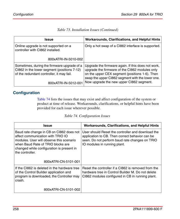
Configuration Section 29 800xA for TRIO
258 2PAA111899-600 F
Configuration
Table 74 lists the issues that may exist and affect configuration of the system or product at time of release. Workarounds, clarifications, or helpful hints have been provided for each issue wherever possible.
Online upgrade is not supported on a controller with CI862 installed.
800xATRI-IN-5010-002
Only a hot swap of a CI862 interface is supported.
Sometimes, during the firmware upgrade of a CI862 in the lower segment (positions 7-12) of the redundant controller, it may fail.
800xATRI-IN-5012-001
Upgrade the firmware again. If this does not work, upgrade the firmware of the CI862 modules only on the upper CEX segment (positions 1-6). Then swap the upper CI862 segment with the lower one. Now upgrade the new upper CI862 segment.
Table 74. Configuration Issues
Issue Workarounds, Clarifications, and Helpful Hints
Baud rate change in CB on CI862 does not affect communication with TRIO IO modules. User will observe this scenario when Baud Rate of TRIO blocks are changed while configuration is present in the controller.
800xATRI-CN-5101-001
User should Reset the controller and download the application to CB. Then correct behavior can be seen. Do not perform baud rate changes on TRIO IO modules in running plant.
If the CI862 is deleted in the hardware tree of the Control Builder application and program is downloaded, the Controller may crash.
800xATRI-CN-5101-002
Reset the controller if a CI862 is removed from the hardware tree in Control Builder M. Do not delete CI862 modules configured in CB in running plant.
Table 73. Installation Issues (Continued)
Issue Workarounds, Clarifications, and Helpful Hints

Section 29 800xA for TRIO Configuration
2PAA111899-600 F 259
IPConfig throws error when PM864 connected with CI862.
800xATRI-CN-5101-003
Set the IP of the controller first using IPCONFIG before connecting the CI862 on the CEX bus.
Problem observed when hot swap of multiple CI862 modules is performed.
For example, four CI862 modules at positions 1,3,7 and 9 exist. The CI862 at position 3 is removed and reinserted.
Before the CI862 at position 3 comes up, CI862 at position 1 is removed and reinserted. After re-insertion, the CI862 at position 1 goes into fault and does not come up.
The controller log shows the following:
Update driver instance Single 1[new:17 old:12] for Index: 1
Single CEM at pos 1 is reset by GIOC Framework[Stat: 0x00000400]
a Hot removal, Hot insert message
Update driver instance Single 1[new:18 old:17] for Index: 1
800xATRI-CN-4000-0002
Insert only one CI862 at a time, wait until it is up and running before inserting the next CI862.
Table 74. Configuration Issues (Continued)
Issue Workarounds, Clarifications, and Helpful Hints

Configuration Section 29 800xA for TRIO
260 2PAA111899-600 F
The user changes the default setting of IN_16CKT for “open wire detection”, “Report fault” and “Short circuit detection” to “False”. After downloading the application to the controller, a Config Error message is shown in the unit status tab of the I/O module.
800xATRI-CN-5012-002
Perform a power reset of the I/O module to remove this message.
CI862 module goes to fault state when a baud rate of 38.4 KB is configured and downloaded from Control Builder.
800xATRI-CN-5020-001
The CI862 does not support baud rate of 38.4 KB.
Signal range settings are lost for the 4IN2OUT block when an earlier version of a Control Builder project is upgraded.
800xATRI-CN-5020-002
Hardware settings for the 4IN2OUT block has changed. Signal Range Channel 1- 4 has been split up in the following two new settings:
Channel High Range and Low Range.
For IO_32CKT block, channel type can only be configured as either input or output.
800xATRI-CN-5020-003
The IO_32CKT block does not support Open Wire diagnostics. Due to this the Tri-State option is not available for the parameter setting "Channel type" for this block.
Repeated re-configuration related to changing the position of CI862 with warm restart may lead to Controller crash.
800xATRI-CN-5020-006
Perform a cold restart of controller after every re-configuration related to position of CI862 module. Do not perform repeated re-configuration related to CI862 in a running plant.
Table 74. Configuration Issues (Continued)
Issue Workarounds, Clarifications, and Helpful Hints

Section 29 800xA for TRIO Operation
2PAA111899-600 F 261
Operation
Table 75 lists the issues that may exist and affect operations of the system or product at time of release. Workarounds, clarifications, or helpful hints have been provided for each issue wherever possible.
User removes both the CI862 in a redundant configuration by removing Primary first and then the other CI862. Configure Non-Redundant Configuration and download it to the controller without any CI862 at the configured position. CI862 does not start and does not communicate.
800xATRI-CN-5020-007
User should make sure that CI862 is inserted at the configured position before downloading.
Table 75. Operational Issues
Issue Workarounds, Clarifications, and Helpful Hints
When the CI862 modules are connected with CEX bus extender module BC810 and power reset is done to the controller, the CI862 modules do not come up after power reset.
800xATRI-OL-5101-002
Reset the controller or conduct hotswap of CI862.
Module remains online even when block ID is changed using HHM. User will observe this scenario when position of TRIO blocks are changed while configuration is present in the controller.
800xATRI-OL-5101-003
User should Reset the controller and download the application to CB. Then the error will be displayed correctly. The Block ID should not be changed in running plant.
Table 74. Configuration Issues (Continued)
Issue Workarounds, Clarifications, and Helpful Hints
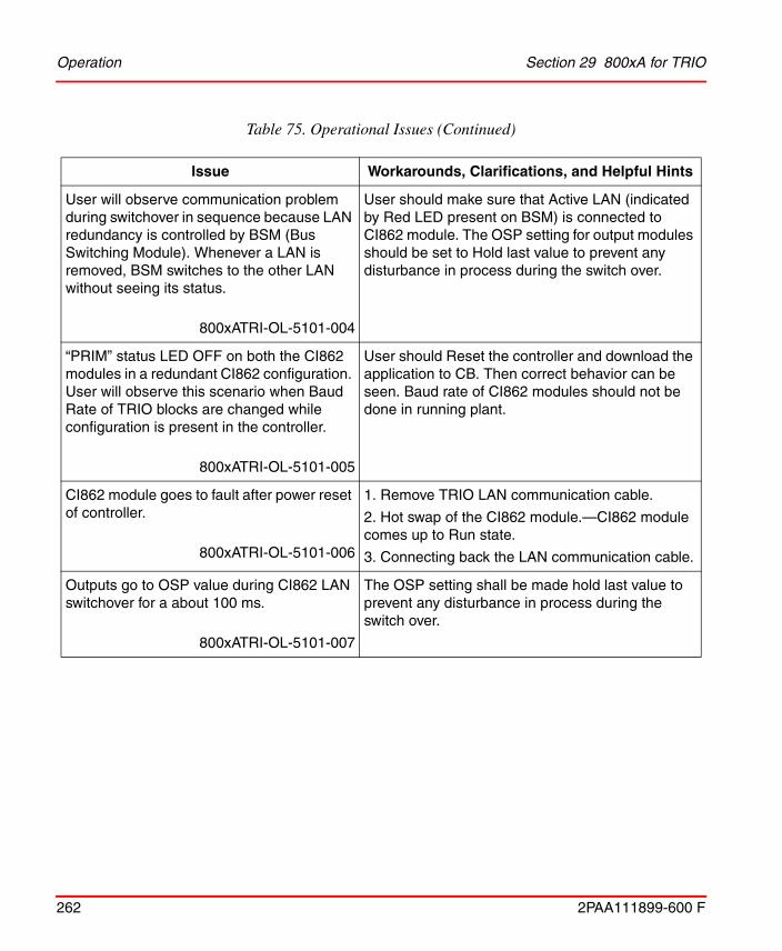
Operation Section 29 800xA for TRIO
262 2PAA111899-600 F
User will observe communication problem during switchover in sequence because LAN redundancy is controlled by BSM (Bus Switching Module). Whenever a LAN is removed, BSM switches to the other LAN without seeing its status.
800xATRI-OL-5101-004
User should make sure that Active LAN (indicated by Red LED present on BSM) is connected to CI862 module. The OSP setting for output modules should be set to Hold last value to prevent any disturbance in process during the switch over.
“PRIM” status LED OFF on both the CI862 modules in a redundant CI862 configuration. User will observe this scenario when Baud Rate of TRIO blocks are changed while configuration is present in the controller.
800xATRI-OL-5101-005
User should Reset the controller and download the application to CB. Then correct behavior can be seen. Baud rate of CI862 modules should not be done in running plant.
CI862 module goes to fault after power reset of controller.
800xATRI-OL-5101-006
1. Remove TRIO LAN communication cable.
2. Hot swap of the CI862 module.—CI862 module comes up to Run state.
3. Connecting back the LAN communication cable.
Outputs go to OSP value during CI862 LAN switchover for a about 100 ms.
800xATRI-OL-5101-007
The OSP setting shall be made hold last value to prevent any disturbance in process during the switch over.
Table 75. Operational Issues (Continued)
Issue Workarounds, Clarifications, and Helpful Hints

Section 29 800xA for TRIO Operation
2PAA111899-600 F 263
If the user removes both CI862 module (or both become faulty) in a redundant CI862 configuration system, the TRIO blocks go to OSP values or holds to the last good value. In Control Builder, the last good value is shown. If one of the CI862 is replaced with a working CI862, the moment the TRIO blocks start communicating with the new CI862, for a short period, the input value goes to zero or the highest value in Control Builder.
800xATRI-OL-5012-004
Use filter in application logic to prevent disturbance in process.
In a redundant CI862 system, if LAN A goes faulty (or CEX module), the communication switches to LAN B. If LAN B also fails, the BSM status shows that the communication switched back to LAN A. Since LAN A is not connected, all modules in that LAN goes to a Block failed status. If the user replaces LAN B (or CEX module) first, communication does not start on LAN B. The BSM still shows that LAN A is the active LAN.
800xATRI-OL-5012-005
Monitor the BSM LED to identify where exactly the TRIO blocks are looking for communication. The LED in the BSM tells exactly where the blocks are looking for communication (if the LED is turned ON, the blocks are looking for communication in LAN B, else LAN A). Based on this information, plug in the new CEX module (or LAN) in the respective CEX position in online mode for all the modules in that LAN. Communication will resume.
If any I/O value of a TRIO block is forced using HHM, there is no specific indication in Control Builder that a value has been forced in that block.
800xATRI-OL-5012-006
"HHM in Use" message will appear in Control Builder in online mode for all the TRIO modules in that LAN. PPA will show an event stating “Block n config changed by HHM” letting the user know something has changed.
Table 75. Operational Issues (Continued)
Issue Workarounds, Clarifications, and Helpful Hints

Operation Section 29 800xA for TRIO
264 2PAA111899-600 F
In a redundant controller and redundant CI862 configuration, if LAN A goes faulty (or CEX module) the communication switches to LAN B. Communication with I/O modules is working properly. However, the CI862 module does not switch over. In this case, if the TRL cable between the primary and secondary CI862 modules becomes faulty, communication of the I/O modules in the LAN stops.
800xATRI-OL-5012-007
TRIO does not support double fault (when the redundant CEX module is also failed). In Control Builder, a warning appears as soon as the TRL cable is disconnected or broken. After this, replace the faulty TRL with a working
one.
When Blocks are communicating to LAN A, and if LAN A goes faulty no information to operator.
800xATRI-OL-5020-001
The operator shall be notified with the event <Blocks have switched to LAN B, Check LAN A>. But if the other LAN (that is, in this case LAN B), through which Blocks are not communicating is removed/Faulty, no information is provided to Operator.
When Blocks are communicating to LAN B, and if LAN B goes faulty, no information is shown to operator.
800xATRI-OL-5020-002
The operator shall be notified with the event <Blocks have switched to LAN A, Check LAN B>. But if the other LAN (i.e. in this case LAN A), through which Blocks are not communicating is removed/Faulty No information is provided to Operator.
After initial download, Latched Extended Status shows the message “Block Failed” for all the blocks.
800xATRI-OL-5020-003
After initial download, either acknowledge latched extended status or issue the “Command 19” with the “Command Channel” for the concerned blocks.
Table 75. Operational Issues (Continued)
Issue Workarounds, Clarifications, and Helpful Hints

Section 29 800xA for TRIO Operation
2PAA111899-600 F 265
The following messages may be received in the PPA:
“Blocks have switched to LAN B, Check LAN A”.
“Blocks have switched to LAN A Check LAN B”.
TRIO has detected the LAN switch.
800xATRI-OL-5020-004
When the LAN through which blocks communicates goes faulty/removed, blocks switch to the other LAN and user would be notified about the same through these events. Check the LAN connections and terminations.
A message may be received in the PPA as follows:
“Check TRL Connection”.
TRIO has detected that there is some fault with TRL Cable.
800xATRI-OL-5020-005
When the TRL Cable connected between the redundant CI862 has been removed or has gone faulty, user is notified about the same with this event in PPA.
CI862 Redundancy Failover is not instantaneous, if it is triggered by removing the RCU Cable from the BC810 connected to backup Controller. This failover may take up to 4 seconds.
800xATRI-OL-5020-006
Do not perform the CI862 switch over by removing the RCU cable from BC810. Instead, the hot swap of primary CI862 module can be done to perform switch over of CI862.
Simultaneous Hot Insertion of two CI862 modules will not work.
800xATRI-OL-5020-007
Insert only one CI862 module at a time. Wait till it comes up, and then insert the other module.
Min, Max and Invert Functionality does not work for RTD and TC blocks.
800xATRI-OL-5020-008
The settings related to Min and Max for RTD and TC blocks can be done by HHM manually.
Table 75. Operational Issues (Continued)
Issue Workarounds, Clarifications, and Helpful Hints

Miscellaneous Section 29 800xA for TRIO
266 2PAA111899-600 F
Miscellaneous
Table 76 list the problems or issues known to exist with the current release that do not fit into one of the other categories. A workaround, when possible, has been identified for each problem or issue.
Table 76. Miscellaneous Issues
Issue Workarounds, Clarifications, and Helpful Hints
Online Help files are not available for TRIO.
800xATRI-MS-5010-005
For more information, refer to 800xA for TRIO/Genius Getting Started (3BUR002459*) and 800xA for TRIO/Genius (3BUR002460*).
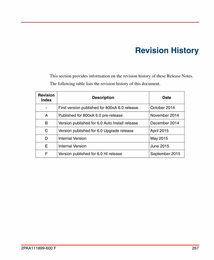
2PAA111899-600 F 267
Revision History
This section provides information on the revision history of these Release Notes.
The following table lists the revision history of this document.
Revision Index
Description Date
- First version published for 800xA 6.0 release. October 2014
A Published for 800xA 6.0 pre-release November 2014
B Version published for 6.0 Auto Install release December 2014
C Version published for 6.0 Upgrade release April 2015
D Internal Version May 2015
E Internal Version June 2015
F Version published for 6.0 HI release September 2015

268 2PAA111899-600 F


Power and productivityfor a better worldTM
Contact us
Copyright © 2015 ABB.All rights reserved.
2PA
A11
1899
-600
Fwww.abb.com/800xAwww.abb.com/controlsystems