800xa history 6.0 administration and configuration€¦ · power and productivity for a better...
TRANSCRIPT

Power and productivity
for a better world™
800xA HistoryAdministration and ConfigurationUser Manual
System Version 6.0


800xA History Administration and Configuration
User Manual
System Version 6.0

NOTICEThis document contains information about one or more ABB products and may include a description of or a reference to one or more standards that may be generally relevant to the ABB products. The presence of any such description of a standard or reference to a standard is not a representation that all of the ABB products referenced in this document support all of the features of the described or ref-erenced standard. In order to determine the specific features supported by a particular ABB product, the reader should consult the product specifications for the particular ABB product.
ABB may have one or more patents or pending patent applications protecting the intellectual property in the ABB products described in this document.
The information in this document is subject to change without notice and should not be construed as a commitment by ABB. ABB assumes no responsibility for any errors that may appear in this document.
Products described or referenced in this document are designed to be connected, and to communicate information and data via a secure network. It is the sole responsibility of the system/product owner to provide and continuously ensure a secure connection between the product and the system network and/or any other networks that may be connected.
The system/product owners must establish and maintain appropriate measures, including, but not lim-ited to, the installation of firewalls, application of authentication measures, encryption of data, installa-tion of antivirus programs, and so on, to protect the system, its products and networks, against security breaches, unauthorized access, interference, intrusion, leakage, and/or theft of data or information.
ABB verifies the function of released products and updates. However system/product owners are ulti-mately responsible to ensure that any system update (including but not limited to code changes, con-figuration file changes, third-party software updates or patches, hardware change out, and so on) is compatible with the security measures implemented. The system/product owners must verify that the system and associated products function as expected in the environment they are deployed.
In no event shall ABB be liable for direct, indirect, special, incidental or consequential damages of any nature or kind arising from the use of this document, nor shall ABB be liable for incidental or conse-quential damages arising from use of any software or hardware described in this document.
This document and parts thereof must not be reproduced or copied without written permission from ABB, and the contents thereof must not be imparted to a third party nor used for any unauthorized pur-pose.
The software or hardware described in this document is furnished under a license and may be used, copied, or disclosed only in accordance with the terms of such license. This product meets the require-ments specified in EMC Directive 2004/108/EC and in Low Voltage Directive 2006/95/EC.
TRADEMARKSAll rights to copyrights, registered trademarks, and trademarks reside with their respective owners.
Copyright © 2003-2015 by ABB.All rights reserved.
Release: October 2015Document number: 2PAA107563-600 B

2PAA107563-600 B 5
Table of Contents
Section 1 - About This User ManualGeneral ..............................................................................................................................9
Document Conventions .....................................................................................................9
Warning, Caution, Information, and Tip Icons..................................................................9
Terminology.....................................................................................................................10
Related Documentation ...................................................................................................11
Section 2 - IntroductionHistory .............................................................................................................................13
History Features...............................................................................................................14
Section 3 - Engineering and ConfigurationOverview..........................................................................................................................17
Configuring Using 800xA ...............................................................................................17
Configuring Using Vtrin..................................................................................................17
Configuring 3rd party OPC AE Server with RTDB.........................................................30
Section 4 - Visualization and Data AccessOverview..........................................................................................................................33
Viewing Numeric Data ....................................................................................................34
Viewing Events Data .......................................................................................................39
OPC Interfaces.................................................................................................................41
Using DCOM Settings for Accessing History DA Server...............................................47
ODBC Interface...............................................................................................................49

Table of Contents
6 2PAA107563-600 B
Section 5 - Maintenance and AdministrationDiagnostic Information for History................................................................................. 55
Start/Stop History Server Database................................................................................. 55
Start/Stop History Embedded Data Collector Database.................................................. 58
Tag Synchronization........................................................................................................ 65
History Database Disk Configuration ............................................................................. 67
Backup and Restore......................................................................................................... 69
System Failure Recovery................................................................................................. 71
Section 6 - Diagnostics and TroubleshootingIntroduction ..................................................................................................................... 75
Tags not Created in 800xA History Embedded Data Collector for 800xA History Logs Created in 800xA ................................................................................................. 75
Events not Appearing in 800xA History Embedded Data Collector .............................. 76
Trends not Appearing in 800xA...................................................................................... 76
Logs not Appearing in 800xA......................................................................................... 76
Redundant 800xA History Embedded Data Collector Node .......................................... 76
Tags not Created in Redundant 800xA History Embedded Data Collector Node .......... 77
Trends not appearing in some client nodes ..................................................................... 77
Checking Logs for RTDB Services................................................................................. 78
800xA History Re-installed............................................................................................. 78
Section 7 - Configuring ArchivesOverview ......................................................................................................................... 79
Configuring Archive Devices.......................................................................................... 81
Configuring Archive Groups........................................................................................... 90
Reading and Managing Archive Data ............................................................................. 98
Appendix A - IP Address ChangeIntroduction ................................................................................................................... 127
History Embedded Data Collector Nodes ..................................................................... 127
800xA History Server.................................................................................................... 128

Table of Contents
2PAA107563-600 B 7
Appendix B - Calculation using C# Calculation FileIntroduction ...................................................................................................................133
Creating Simple Calculation..........................................................................................134
Appendix C - History SupervisionIntroduction ...................................................................................................................155
History Supervision Aspect ...........................................................................................155
Appendix D - Diagnostic Information for 800xADiagnostic Information for 800xA History ...................................................................159
Start/Stop History Server Database ...............................................................................159
Start/Stop 800xA History Embedded Data Collector Database ....................................163
Appendix E - History Sync Service During Network Disconnection
Appendix F - Password Update ProcedurePassword Update Procedure on the History Server:......................................................173
Password Update Procedure on the Data Collector:......................................................174
Appendix G - Accessing 800xA History DA ServerAccessing 800xA History DA Server Using DCOM Settings ......................................177
Appendix H - User Name Update ProcedureUser Name Update Procedure on the 800xA History Server and 800xA History DCN nodes
179
Revision HistoryUpdates in Revision Index A.........................................................................................183
Updates in Revision Index B .........................................................................................184
Index

Table of Contents
8 2PAA107563-600 B

2PAA107563-600 B 9
Section 1 About This User Manual
GeneralAny security measures described in this User Manual, for example, for user access, password security, network security, firewalls, virus protection, etc., represent possible steps that a user may want to consider based on a risk assessment for a particular application and installation. This risk assessment, as well as the proper implementation, configuration, installation, operation, administration, and maintenance of all relevant security related equipment, software, and procedures, are the responsibility of the user.
This user manual is the Administration manual for History. This user manual provides an overview of basic navigation, creating history logs and tags, viewing reports, calculations, data retrieval, table definitions, maintenance and administration of Data Collector Node and History Server.
Document ConventionsMicrosoft Windows conventions are normally used for the standard presentation of material when entering text, key sequences, prompts, messages, menu items, screen elements, etc.
Warning, Caution, Information, and Tip IconsThis publication includes Warning, Caution, and Information where appropriate to point out safety related or other important information. It also includes Tip to
Terminology Section 1 About This User Manual
10 2PAA107563-600 B
point out useful hints to the reader. The corresponding symbols should be interpreted as follows:
Although Warning hazards are related to personal injury, and Caution hazards are associated with equipment or property damage, it should be understood that operation of damaged equipment could, under certain operational conditions, result in degraded process performance leading to personal injury or death. Therefore, fully comply with all Warning and Caution notices.
TerminologyThis section includes a complete and comprehensive list of terms that apply to the History application. Terms that uniquely apply to this instruction are included in this section.
Electrical warning icon indicates the presence of a hazard which could result in electrical shock.
Warning icon indicates the presence of a hazard which could result in personal injury.
Caution icon indicates important information or warning related to the concept discussed in the text. It might indicate the presence of a hazard which could result in corruption of software or damage to equipment/property.
Information icon alerts the reader to pertinent facts and conditions.
Tip icon indicates advice on, for example, how to design the project or how to use a certain function
Term/Acronym Description
GUI Graphical User Interface
MSI Microsoft Installer
CLS Central Licensing System
Section 1 About This User Manual Related Documentation
2PAA107563-600 B 11
Related Documentation
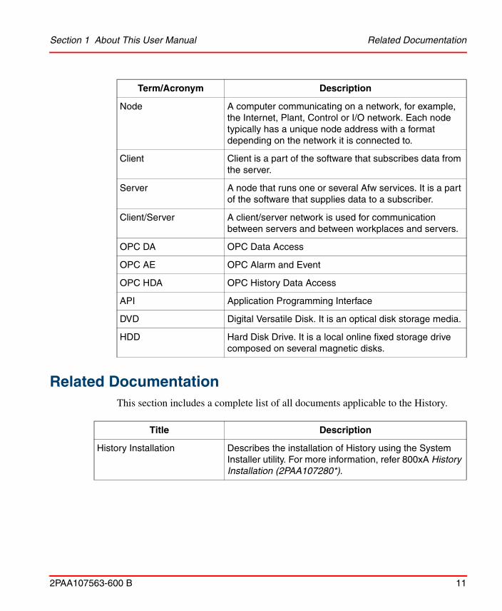
This section includes a complete list of all documents applicable to the History.
Node A computer communicating on a network, for example, the Internet, Plant, Control or I/O network. Each node typically has a unique node address with a format depending on the network it is connected to.
Client Client is a part of the software that subscribes data from the server.
Server A node that runs one or several Afw services. It is a part of the software that supplies data to a subscriber.
Client/Server A client/server network is used for communication between servers and between workplaces and servers.
OPC DA OPC Data Access
OPC AE OPC Alarm and Event
OPC HDA OPC History Data Access
API Application Programming Interface
DVD Digital Versatile Disk. It is an optical disk storage media.
HDD Hard Disk Drive. It is a local online fixed storage drive composed on several magnetic disks.
Title Description
History Installation Describes the installation of History using the System Installer utility. For more information, refer 800xA History Installation (2PAA107280*).
Term/Acronym Description

Related Documentation Section 1 About This User Manual
12 2PAA107563-600 B

2PAA107563-600 B 13
Section 2 Introduction
HistoryHistory helps to collect information from the sensor to the executive's desktop. It is designed to be a high-performance process historian for the management of real-time data and events.
It reliably gathers and serve large volumes of data. It delivers information to the right people at the right time and brings system and people together. It provides access to history data through standard interface like OPC and ODBC and insulates the automation system from the applications accessing the process data. It provides view of operational information inside the Smart Client and external applications like Microsoft Excel reports.
The key objectives of History are:
1. Traditional historian with RDBMS functions.
2. Fault tolerant and remote data collection.
3. High performance storage of process and event data.
4. Aggregates and user defined calculations for raw data.
5. Firewall friendly, secure connectivity.
6. Provides long term on-line data storage.
7. Standard data access interfaces - OPC®, ODBC.

History Features Section 2 Introduction
14 2PAA107563-600 B
History Features
History comprises of the following features:
• History Server
• History Embedded Data Collector
Figure 1. History Layout

Section 2 Introduction History Server
2PAA107563-600 B 15
History Server
History Server is responsible for storing raw data and aggregated data from the control system. It stores the raw data in Real time database and aggregates the same data. History also stores events and manages system configuration. It provides open interfaces for external applications.
History server consists of an internal Real Time Database. Real Time Database is used for raw data storage and buffering, which is designed and optimized for process information management and extensive history recording. High performance and reliability of Real Time Database, together with maintenance free operation, provide a solid platform for mission-critical systems. Real Time Database combines the benefits of an easy-to-use relational desktop database with industrial reliability, performance and real-time functionality to provide an excellent platform for process information management.
History Embedded Data Collector
History Embedded Data Collector is a node in History architecture, which is responsible for data buffering of raw OPC data. History Embedded Data Collector stores the raw data in the real time database, which is a part of Data Collector Node. The raw data is stored in the real time database for seven days in the Data Collector Node, which is sent to History server.
The following are the features of History Embedded Data Collector:
• It can be configured to execute in pairs.
• It provides interfaces for data access.
• It is very simple to install and has a fixed data model for storage based on purpose.
• It can be embedded in other applications.
• The engineering is driven from History server in the History architecture.
Redundant Data collectors will be preferable configuration for the Data Collection to the History Server.

History Embedded Data Collector Section 2 Introduction
16 2PAA107563-600 B

2PAA107563-600 B 17
Section 3 Engineering and Configuration
OverviewThis section describes the configuration of History. Every data point stored in the History server is called Tag. User can configure the Tag properties to tune the update rate, compression etc. for data storage.
A Tag can be created and configured in the following ways:
1. Configuring Using 800xA
2. Configuring Using Vtrin
3. Configuring 3rd party OPC AE Server with RTDB
In High Availability Server Configuration, make sure to keep the First Node of High Availability Server Up and Running before you begin creating tags in DCN.
To configure History Logs using 800xA, please refer to 800xA System Configuration (3BDS011222*)
Configuring Using 800xARefer System 800xA Configuration (3BDS011222*) for configuring tag using 800xA.
Configuring Using VtrinTag creation is typically done for configuring 3rd party logs. The tag in the History database is a container object which has definition for the data collection from the various data source (i.e, primarily OPC Sources). Other than the data collection
800xA History supports 20,000 unique paths for creation of signals.

Configuring Using Vtrin Section 3 Engineering and Configuration
18 2PAA107563-600 B
definition the tag objects contains definition for the Data Type of the tag, Update Rate with which the data is collected and many other definitions which will be explained in this section.
For each tag created in database there is an associated Variable created which represents the current value update of the tag as well current history data, aggregates data can be accessed via trends in VTrin GUI with Variables. Further details on variables can be found in section Variables.
Perform the following steps to create the tags manually:
1. Go to Windows> Search for Vtrin and open with Run as Administrator.
2. Navigate to Maintenance > Basics > Tag Configurations, to open the Tag List on the right pane.
Figure 2. Tag Configuration path

Section 3 Engineering and Configuration Configuring Using Vtrin
2PAA107563-600 B 19
3. Right-click the tabs in the Tag window to view the context menu as shown in Figure 3.
Figure 3. Tags List - context menu
4. Click New to view a Properties window for the new tags.

Configuring Using Vtrin Section 3 Engineering and Configuration
20 2PAA107563-600 B
5.
Figure 4. Tags - General tab
In the General Tab, fill in the mandatory fields.

Section 3 Engineering and Configuration Configuring Using Vtrin
2PAA107563-600 B 21
For more information on the available fields in General tab, refer Table 1.
Table 1. General Tab - Available Fields
Field name Description
Proposed Name The name of the tag that is required in the database. This is a mandatory field.
Description Description of the Tag. This is an optional field. By default, the Description field will be blank.
Type Data type of the Tag. This is a mandatory field. By default, the data type will be Float or Real. Various options such as Float, Binary, Int, String are included in this field.
Data Flow Direction Defines the direction of the data flow. This is a mandatory field. The options are [in] and [Out]. By default, the value [in] is selected. If [in] is selected, the Tag will be read-only. Select [out] to make the tag Read-Write enabled.
Display Format Defines the format of the tag display. This becomes a mandatory field when the Type field is selected as Float. If a Float tag type is defines, then the Display Format is used to define the no. of digits after the decimal point, Ex. 0.0, 0.00, 0.000.
Unit Engineering unit of the tag. This is an optional field. By default, the value for this field will be blank.
Equipment Path This enables the user to group tags of similar category, area etc.Though this is not a mandatory field, it is recommended to define this. By default, the value for this field is none. Example for Equipment Path definition are Path1.Path2.Path3.
Creator This field denotes the name of the source of the tag. The user can mention the node type (like History Server or DCN etc.) manually.This is an optional field. The default value is blank.

Configuring Using Vtrin Section 3 Engineering and Configuration
22 2PAA107563-600 B
6. Click Current Data Collection tab and fill the details of tag collection, activation fields as shown in Figure 5.
Figure 5. Current Data Collection tab
For more information on the available fields, refer Table 2.

Section 3 Engineering and Configuration Configuring Using Vtrin
2PAA107563-600 B 23
Table 2. Current Data Collection - Fields and Description
Field name Description
Activity Drop-down menu to enable or disable storing data in history server. This is a mandatory field. By default, Inactive will be selected. This will not update the tag data. If Active is selected, the tag stores the data in history.
Protocol type Denotes the type of OPC Protocol to be used. OPC DA to be selected for a DA subscription and OPC UA for UA subscription
Path For OPC DA: Denotes the OPCDA path for the tag to subscribe data. Format for specifying this field is: opcda://NODENAME(OR IP)/DA SERVER PROGID/DA SERVER CLSID/TAG Link.
For example, if Matrikon OPC DA Explorer is used, for a tag called Random, NODENAME(OR IP): If localhost, then Leave this section blank.Otherwise, give node name or IP from the node it is subscribed. Remember to do DCOM settings if the data is to be subscribed from other Node.
DA SERVER PROGID: Matrikon.OPC.Simulation.1
DA SERVER CLSID: {F28134-XXXX-XXXX-XXXX}
TAGNAME: Random.Real4
So the string will be:
opcda:///Matrikon.OPC.Simulation.1/{F28134-XXXX-XXXX-XXXX}/Random.Real4
If OPC server is used as remote server then make sure OPC server executable is exempted from firewall.

Configuring Using Vtrin Section 3 Engineering and Configuration
24 2PAA107563-600 B
For OPC UA: Denotes the OPC UA path for the tag to subscribe data.
The syntax for OPC UA path is: opc.tcp://nodename:port/progid//ItemId;namespace=name
For example:
opc.tcp://fi8-main:4841///Variable.SYS_CPU0_Time;UaNamespace=http://fi.abb.com/Vtrin
The progid value is just some name that can be used if multiple connections to the same OPC UA server is wanted to be configured. If the ProgId is present, the SID name for the connection is nodename_port_progid. If ProgId is not present, the SID name is just nodename_port. (The SID name is just an identifying name for the server connection in the RTDB OPC client. The SID name is present in the diagnostic messages, and also in the name of the Item Report file ("EcOpcClient-ItemReport-sid.txt"). The DaPath has also space for a class id name after the progid. The class id should be left as empty.The namespace definition can be omitted if a default has been defined in SimpleConfig setting AppName/SID_sid as "NameSpace=name".
For example:
insert into SimpleConfig(SectionName,KeyName,StrValue) values('RTDB-EcOpcClient', 'SID_fi8-main_4841', 'UaNamespace=http://fi.abb.com/Vtrin')
Enable Redundant Data Collection
Check box to indicate if the data is to be collected from Redundant DA Server Source. By default, this check box will not be selected. If this check box is selected, then provide the path details in the Path field.
Frequency Provide the Frequency (or Update Rate) for this tag to be read by the History DA Client. By default, the value for this field will be 1000 ms.
Deadband Field to indicate if deadband needs to be applied for the tag. By default, the value for this field is 0.
Table 2. Current Data Collection - Fields and Description (Continued)
Field name Description

Section 3 Engineering and Configuration Configuring Using Vtrin
2PAA107563-600 B 25
7. Click History Data Collection tab and fill in the available fields as shown in Figure 6.
Figure 6. History Data Collection tab

Configuring Using Vtrin Section 3 Engineering and Configuration
26 2PAA107563-600 B
For more information on the available fields, refer Table 3.
Table 3. History Data Collection tab- Fields and Description
Field name Description
History Collection Template
If aggregation is required, then click the appropriate option in the History Collection Template field. This is an optional field. By default, None is selected. Various options available are AVG,CNT, DEV,FOR,FVA,LVA,MAX, MIN,OPT,SUM.
If multiple type of Aggregation required, select AVG;CNT;DEV

Section 3 Engineering and Configuration Configuring Using Vtrin
2PAA107563-600 B 27
8. Click Processing Tab and fill in the Compression Error filed as shown in Figure 7.
Figure 7. Processing tab

Configuring Using Vtrin Section 3 Engineering and Configuration
28 2PAA107563-600 B
For more information on the available fields, refer Table 4.
Table 4. Processing Tab - Fields and Description
Field name Description
Compression Error If compression for storing of the tags is required then user is required to enter here as, 0.1,0.2 (show as equivalent of Percentage) etc. By default, the value for this field will be 0.

Section 3 Engineering and Configuration Configuring Using Vtrin
2PAA107563-600 B 29
9. Click Hierarchy tab and enter the values for the appropriate fields as shown in Figure 8.
Figure 8. Hierarchy tab

Configuring 3rd party OPC AE Server with RTDB Section 3 Engineering and Configuration
30 2PAA107563-600 B
For more information on the available fields, refer Table 5.
10. Click Apply and then click OK to create the tag on the History Server.
Configuring 3rd party OPC AE Server with RTDBThe RTDB-EcOPCClient is capable of accessing DA as well as AE data from respective servers. The DA access is enabled by default.
To access AE Data you need to do additional configuration in DCN. Following are the steps for configuring 3rd party OPC AE server with RTDB.
1. Record the ProgID of the AE Server. For example Freelance2000OPCAEServer050.
2. Record the CLSID of the AE Server. You can find this in Registry by searching for the ProgID as mentioned above.
3. Run the following commands from the Command Prompt (replace only the CLS ID only in the step a.
a. praotstx %APP_DSN% -sql "INSERT INTO eccrossrefs (ProcNumber, TimeClass, OrderBy, CommType, LocalId, RemoteId) VALUES(4, 0, 0, 'OPCSRV', 'SID=OPCAECLIENT',
Table 5. Hierarchy tab
Field name Description
Enable Consistency Control
If check, it will allow to replicate the tag to DCN (if Tag created in History Server Directly) or will replicate to History Server (If the tag is created in DCN directly). By default, this check box will not be selected.
Collector Node If Enable Consistency Control is checked, then in this entry a user is required to select the Appropriate DCN Node. By default, the value will be None.
If OPC server is used as remote server then make sure OPC server executable is exempted from firewall.

Section 3 Engineering and Configuration Configuring 3rd party OPC AE Server with RTDB
2PAA107563-600 B 31
'DA=0;AE=1;node=127.0.0.1;ClsId={6211C2F8-D24C-11d3-8D0D-00C04F60F050}')"
b. praotstx %APP_DSN% -sql "INSERT INTO eccrossrefs (ProcNumber, TimeClass, OrderBy, CommType, LocalId, RemoteId) VALUES(4, 661, 0, 'OPCAES', 'EID=Events', 'SID=OPCAECLIENT;SOURCES=*')"
4. After the above commands are run. Restart the RTDB-EcOpcClient in DCN using Windows Service Control Manager.

Configuring 3rd party OPC AE Server with RTDB Section 3 Engineering and Configuration
32 2PAA107563-600 B

2PAA107563-600 B 33
Section 4 Visualization and Data Access
OverviewThis section describes the procedure for retrieval and viewing the numeric and event data.
• Viewing Numeric Data
– Using DataDirect
– Using Trend Display
• Viewing Events Data
– Viewing Events on Duration Basis
– Viewing Events on Specific Time and Date
This section also describes the data access interfaces supported by History. The data access interfaces provide connectivity to the history data and facilitate the data exchange with the 3rd party applications like Enterprise Systems, report generation tools etc.
Following connectivity is supported via standard interfaces:
1. OPC DA to access real time data.
2. OPC HDA to access history data.
3. OPC UA to access real time and history data.
4. ODBC to access numeric as well as event data.

Viewing Numeric Data Section 4 Visualization and Data Access
34 2PAA107563-600 B
Viewing Numeric Data
Using DataDirect
OPC Data and History data can be accessed using an MS Excel add-in DataDirect.
Open MS Excel and the select the Add-Ins tab to use the Industrial IT functions of DataDirect.
Industrial IT Process Values
Using the Industrial IT Process Values function, the current value of the selected object Property can be retrieved to MS Excel.
To access DataDirect functions other than the installed account, manually add the DataDirect add-in to the excel by browsing to the path, C:\ProgramData\ABB\IM\DataDirect\Bin\ABBDataDirect.xla.
Usage of DataDirect requires DataDirect license. For more information about DataDirect, refer System 800xA Information Management Data Access and Reports (3BUF001094*).
Figure 9. DataDirect - Industrial IT Process Values command

Section 4 Visualization and Data Access Using DataDirect
2PAA107563-600 B 35
Figure 10. PPA Process Values

Using DataDirect Section 4 Visualization and Data Access
36 2PAA107563-600 B
Industrial IT History Values
Using this function, the history data can be retrieved to MS Excel.
Figure 11. DataDirect - Industrial IT History Values command

Section 4 Visualization and Data Access Using Trend Display
2PAA107563-600 B 37
Using Trend Display
Trend display is used to plot traces in a graphical manner. The 800xA History server collects historical data from 800xA System, which can be plotted in a trend display.
For visualizing seamless trends a basic history log should be created along with the 800xA History log in the 800xA History Log template.
The minimum time of the Basic History log and the 800xA History log update rate should be the same.
Figure 12. Industrial IT History Values

Using Trend Display Section 4 Visualization and Data Access
38 2PAA107563-600 B
Configuring Trend Display
For more information about Trend Display Aspects, refer to System 800xA Information Management Display Services (3BUF001093*).
1. Create Trend Display aspect.
2. Double-click Trend Display aspect. The Trend Display window appears as shown in Figure 13
Figure 13. Trend Display window
By default, the Trend Display uses the default trend template. To modify the trend template, select Config View and select the required template from the Trend Template drop-down list.
3. Click Object Name field in the Trend Display window. The Select Object window appears.

Section 4 Visualization and Data Access Viewing Events Data
2PAA107563-600 B 39
4. Select the required object and click OK. The selected object is available in the
Object Name field.
5. Object can be dragged and dropped from the plant explorer into the Object Name field. The Trend display is started.
Viewing Events DataAfter the 3rd OPC AE configuration is completed, the events are automatically moved to History Embedded data collector.
Use one of the following methods to view the events in Vtrin:
Viewing Events on Duration Basis
Perform the following steps to view the events on duration basis:
1. Select the Enable Mask check box.
2. In the EventTime status bar, click the appropriate duration from the drop-down menus. For example, for viewing events for 1 hour, click 1 from the first
Figure 14. Select Object window
History events from History can only be viewed using Vtrin and ODBC interface.

Viewing Events by Specific Time and Date Section 4 Visualization and Data Access
40 2PAA107563-600 B
drop-down menu and then click Hour(s) option from the second drop-down menu as shown in Figure 15. The events for the selected duration appears in the main window.
Figure 15. Viewing Events by Duration
Viewing Events by Specific Time and Date
Perform the following steps to view the events by querying for specific time:
1. Select the Enable Mask check box.
2. Click the pin icons on the EventTime status bar as shown in Figure 16 to enable time specific selection.
3. Select the applicable date from the first drop-down menu.
4. Select the appropriate time from the second drop-down menu.

Section 4 Visualization and Data Access OPC Interfaces
2PAA107563-600 B 41
A list of events pertaining to specific date and time appears in the main window.
OPC InterfacesOPC is used to bridge Windows based software applications and process control hardware, control system. OPC Data Access is a group of standards that provides specifications for communicating real-time data from data acquisition control system. The OPC Data Access specification is also known as OPC DA. OPC DA deals only with real-time data.
OPC Historical Data Access, also known as OPC HDA, is used to exchange archived process data. It provides COM specifications for communicating data from devices and applications that provide historical data, such as databases. The specifications provides for access to raw, interpolated and aggregate data.
OPC Unified Architecture (UA) is a platform independent interface specification for data communication between History database and OPC Clients or Servers. OPC UA specification uses TCP/IP or Web Service for data communications.
Figure 16. Viewing Events by Time and Date

OPC DA Section 4 Visualization and Data Access
42 2PAA107563-600 B
OPC DA
OPC DA facilitates History Data transfer from History Embedded Data Collector Node to History Server. RealTime History - Opc DA Server is the service responsible for transferring real time data and object path from History Embedded Data Collector Node to History server and representing it in OPC Client.
Figure 17 shows the existence of the History OPC DA Server. The DA Server is available in both History Embedded Data Collector Node as well as the History Server Node.
Figure 17. Data From History Embedded Data Collector Node To History Server

Section 4 Visualization and Data Access OPC DA
2PAA107563-600 B 43
The real time data can be extracted from History server through OPC DA interface available for the History Server.
Figure 18. RealTime History-OpcDaServer Service For Real Time Data And Object Path

OPC HDA Section 4 Visualization and Data Access
44 2PAA107563-600 B
OPC HDA
OPC HDA service facilitates History Data Transfer from History server to History Embedded Data Collector Node. The Historical Data can also be made available to any other applications using the HDA interface available on the History Server side.
Figure 19. History Data Transfer From History Server To Data Collector Node

Section 4 Visualization and Data Access OPC HDA
2PAA107563-600 B 45
CpmPlusKM-OpcHdaServer is the service responsible for sending historical data from History server to History Embedded Data Collector Node.
Figure 20. CpmPlusKM-OpcHdaServer Service For Historical Data

OPC UA Section 4 Visualization and Data Access
46 2PAA107563-600 B
OPC UA
OPC UA Server is installed only on History Server(s) by default and not installed in Data Collectors. Any OPC UA client can connect to OPC UA Server of History and subscribe data.
Perform the following steps to have the OPC UA Clients access the History data via RTDB-OPCUaServer service of History Server.
1. In History Server, navigate to <RTDBDatabaseDrive>\Application\Config\OpcIniFiles and edit the file RTDBOpcUaServerConfig.
Figure 21. RTDB-OPCUaServer

Section 4 Visualization and Data Access Using DCOM Settings for Accessing History DA Server
2PAA107563-600 B 47
2. Modify the Security Setting as shown in the following screen.
Figure 22. Modification of RTDBOpcUaServerConfig file
3. Save and Close the file
RTDB-EcOpcClient, using OPC UA Specification 1.01, can subscribe data from OPC UA Servers which can further be processed and stored in History Server.
Using DCOM Settings for Accessing History DA ServerWhen configuring OPC client to access History DA Server, ensure that client machine is in Workgroup or Domain Environment.

Workgroup Environment Section 4 Visualization and Data Access
48 2PAA107563-600 B
Refer important information related to DCOM settings required for accessing History DA server mentioned below.
Workgroup Environment
In workgroup environment, if the OPC Client PC is in same workgroup as History DA Server then following should be done.
• There should be a common user account for running both OPC Server and OPC Client.
• If the OPC Server and OPC Client are running with different user account, then, these local user accounts should be available in both PC. For example, if the OPC Server runs with local user account 'A' and OPC Client runs with user account 'B' then both local user 'A' and 'B' should be available in OPC Server (For example, History Server Node) as well as OPC Client Node. It is not mandatory that these user account have same password.
Domain Environment
When the History DA Server and Client PC are in same domain
Ensure that domain user accounts are used for running the OPC Server as well as OPC Client. So, in this case, no need to create users in each PC (as it is done in workgroup environment.)
Ensure to have administrative privileges to create user accounts that are mentioned in the following description.
Ensure that the user account is set properly for DCOM settings. For example, the username in case of domain user account will be like 'DomainName\Username'. Before doing the DCOM settings, please make sure that both the OPC Server and the OPC Client are running with the same domain user account.
If the local user account is used for DCOM settings, then this user account should be consistent in Server and Client PC.

Section 4 Visualization and Data Access Workgroup to Domain Environment
2PAA107563-600 B 49
When the History DA Server and Client PC are in different domain
When the History DA Server and Client PC are in different domain, first, ensure that to setup a 'Trust Relationship' between both domains. Please contact your system administrator for configuring the 'Trust Relationship' between domains.
Workgroup to Domain Environment
This scenario is a little bit complicated as compared to what we have seen in case, when both Server and Client PCs are either in Workgroup or Domain Environment.
Make sure that when one PC is in domain and other is in workgroup, the workgroup cannot authenticate domain user account.
So to make the Workgroup and Domain environment inter-operate, ensure to have local user account defined in both Server and Client PC. Following are important points to consider:
• OPC Server must run as a local user account. This local user account should be available in both Server and Client PC with same username and password.
• OPC Client must run as a local user account on the client PC and that same local user account must exist on the OPC Server PC with the same username and password.
ODBC InterfaceODBC stands for Open Data Base Connectivity. It is a standard for accessing different database systems. Any application can use ODBC to query data from a database, regardless of the platform it is on or DBMS it uses. It is a connection that is created to define a connection between a computer and a database stored on the same or another system.
The History provides ODBC Connectivity via the ODBC Interface option available with the History Database. Queries can be made to various tables available in the database to achieve the required results.
Configuring Excel Data Source
The History database can be exported to MS Excel using the ODBC Interface. For exporting the Historical Data, a Data source has to be defined in MS Excel.

Configuring Excel Data Source Section 4 Visualization and Data Access
50 2PAA107563-600 B
Perform the following procedure to configure the Data source.
1. Open MS Excel. From the Data tab, select Get External Data > From Other Sources > From Data Connection Wizard as shown in Figure 23. The Data Connection Wizard appears as shown in Figure 24
Figure 23. Excel - From Data Connection Wizard command

Section 4 Visualization and Data Access Configuring Excel Data Source
2PAA107563-600 B 51
2. In the Data Connection Wizard, select ODBC DSN and then click Next to view the Select Database and Table screen as shown in Figure 25.
Figure 25. Data Connection Wizard - Select Database and Table screen
Figure 24. Data Connection Wizard

Configuring Excel Data Source Section 4 Visualization and Data Access
52 2PAA107563-600 B
3. Select OpcEventLog_All or other tables if required and then click Next to view the Save Data Connection File and Finish screen as shown in Figure 26.
Figure 26. Data Connection Wizard - Save Data Connection File and Finish screen
4. Select the Always attempt to use this file to refresh data checkbox and then click Finish to view the Import Data wizard as shown in Figure 27.
Figure 27. Import Data wizard

Section 4 Visualization and Data Access Configuring Excel Data Source
2PAA107563-600 B 53
5. Select the desired format for Data Export and then click OK. The Historical Data gets exported in the desired format. Figure 28 shows the Excel sheet of exported data.
Figure 28. Excel sheet - Exported data

Configuring Excel Data Source Section 4 Visualization and Data Access
54 2PAA107563-600 B

2PAA107563-600 B 55
Section 5 Maintenance and Administration
Diagnostic Information for HistoryThe following information is common for History Embedded Data Collector as well as History Server Node.
The diagnostic information is written to text files and can be accessed from the following location:
From Desktop, open RTDB Control Panel folder and then navigate to Diagonistics Tools > View Latest Log Files > Diag. Alternatively, Diag folder can also be accessed by clicking Start > Run, typing, %app_datapath%\diag and then pressing Enter.
The Diag folder contains the log files for all the related services of History or DC as well it contains various logs for the runtime processes by the database.
Additionally, the live diagonistic messages can be viewed for the specific services by the running the batch files available at following location: Desktop > RTDB Control Panel > Diagonistic Tools.
Start/Stop History Server DatabaseStarting and Stopping the Database can be carried out by various methods. However, it is advised to use the batch file called Start RTDB/ Stop RTDB available in the Desktop in folder RTDB Control Panel.
Starting Database using RTDB Control Panel
To start the database:

Starting Database using RTDB Control Panel Section 5 Maintenance and Administration
56 2PAA107563-600 B
1. Double-click the RTDB Control Panel folder shortcut icon on the desktop. Three folders as shown in Figure 29 appears.
Figure 29. Folders in RTDB Control Panel
2. Double-click the Start and Stopping folder to open it. The Start RTDB and Stop RTDB batch files appears as shown in Figure 30.
Figure 30. Start and Stop RTDB batch files (selected)
3. Double-click the Start RTDB batch file to start the main real time database service in Data Collector Node.

Section 5 Maintenance and Administration Stopping Database using RTDB Control Panel
2PAA107563-600 B 57
Stopping Database using RTDB Control Panel
To stop the Database:
1. Double-click the RTDB Control Panel folder shortcut icon on the desktop. Three folders as shown in Figure 29 appears.
Figure 31. Folders in RTDB Control Panel
2. Double-click the Start and Stopping folder to open it. The Start RTDB and Stop RTDB batch files appears as shown in Figure 30.
Figure 32. Start and Stop RTDB batch files (selected)

Start/Stop History Embedded Data Collector Database Section 5 Maintenance and Administration
58 2PAA107563-600 B
3. Double-click the Stop RTDB batch file and type ‘Y’ in the confirmation prompt as shown in Figure 33 to stop the main real time database service in History Embedded Data Collector Node.
Figure 33. Confirmation Prompt for stopping RTDB
Once the Database stopping process is completed, the system displays the message “RTDB-service has now been stopped. All tables are OK”.
Start/Stop History Embedded Data Collector DatabaseTo stop the 800xA History Embedded Data Collector database perform one of the following methods:
1. Start/Stop the database from the database control panel.
– To start the database, refer Starting Database using RTDB Control Panel.
– To stop the database, refer Stopping Database using RTDB Control Panel.
2. Start/Stop Database from ABB System 800xA Service Structure.
– To start the database from 800xA Service Structure, refer Starting Database from ABB System 800xA.
– To stop the database from 800xA Service Structure, refer Stopping Database From ABB System 800xA.
Section 5 Maintenance and Administration Starting Database from ABB System 800xA
2PAA107563-600 B 59
Starting Database from ABB System 800xA
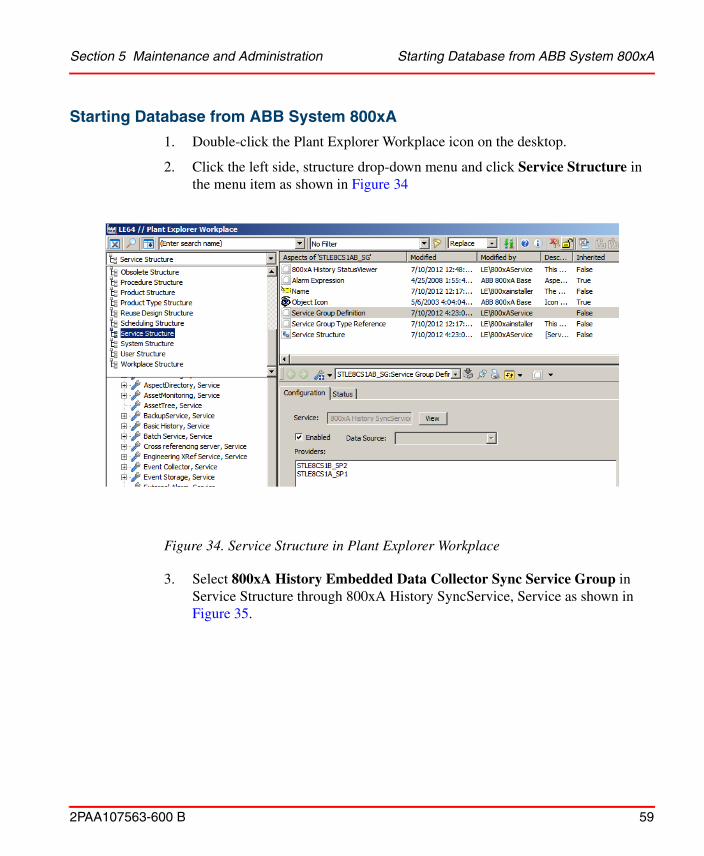
1. Double-click the Plant Explorer Workplace icon on the desktop.
2. Click the left side, structure drop-down menu and click Service Structure in the menu item as shown in Figure 34
Figure 34. Service Structure in Plant Explorer Workplace
3. Select 800xA History Embedded Data Collector Sync Service Group in Service Structure through 800xA History SyncService, Service as shown in Figure 35.

Starting Database from ABB System 800xA Section 5 Maintenance and Administration
60 2PAA107563-600 B
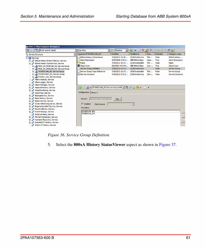
4. By default, the Service Group Definition is selected in the right pane as shown
in Figure 36.
Figure 35. Sync Service in Service structure
Section 5 Maintenance and Administration Starting Database from ABB System 800xA
2PAA107563-600 B 61
5. Select the 800xA History StatusViewer aspect as shown in Figure 37.
Figure 36. Service Group Definition

Starting Database from ABB System 800xA Section 5 Maintenance and Administration
62 2PAA107563-600 B
6. Click 800xA History Service Manager as shown in Figure 38.
Figure 37. 800xA History Status Viewer

Section 5 Maintenance and Administration Starting Database from ABB System 800xA
2PAA107563-600 B 63
7. Check the appropriate Service Provider as shown in Figure 39 in the 800xA
History Services window and click Start.
Figure 38. 800xA History Service Manager
Figure 39. 800xA History Services Window

Stopping Database From ABB System 800xA Section 5 Maintenance and Administration
64 2PAA107563-600 B
Stopping Database From ABB System 800xA
1. Double-click the Plant Explorer Workplace icon on the desktop.
2. Click on the left side, structure drop down menu and select Service Structure in the menu item as shown in Figure 34.
3. Select 800xA History Embedded Data Collector Sync Service Group in Service Structure through 800xA History SyncService, Service in the left pane of Service Structure as shown in Figure 35.
4. By default, the Service Group Definition is selected in the right pane as shown in Figure 36
5. Select 800xA History StatusViewer as shown in Figure 37.
6. Click 800xA History Service Manager as shown in Figure 38.
7. Check the appropriate Service Provider in 800xA History Service Manager as shown if Figure 40 and click Stop.
Figure 40. 800xA History Services

Section 5 Maintenance and Administration Tag Synchronization
2PAA107563-600 B 65
Tag SynchronizationRealTime History-TagConsistencyController is the service responsible for tag synchronization between the Data Collector Node and History Server.
Figure 41. RealTime History-TagConsistencyController Service For Tag Synchronization

Tag Synchronization Section 5 Maintenance and Administration
66 2PAA107563-600 B
RealTime History-EventForwarder is the service responsible to pull the events from the Data Collector Node to the History Server.
Figure 42. RealTime History-EventForwarder Service For Events

Section 5 Maintenance and Administration History Database Disk Configuration
2PAA107563-600 B 67
VtrinLink is the service responsible for real time and historical data transfer between the Data Collector Node and History Server.
History Database Disk ConfigurationThe Database disk is located on a separate data disk (hard disk drive) and the software is located on another disk. For performance reasons it is most desirable, whenever possible, to have the disk containing database to be formatted using 64 kB (kilo bytes) block size.
Figure 43. VtrinLink Service For Real Time And Historical Data Transfer

History Database Disk Configuration Section 5 Maintenance and Administration
68 2PAA107563-600 B
A very typical disk configuration is the following:
It is possible to make more complex and extremely sizeable disk configurations with high redundancy and high performance for History Database. A very typical larger configuration setup looks like this:
Table 6. Typical Disk Configuration
Disk Description
C: Operating System and Product Software
D: History Database and project specific application files. The allocation unit size of this disk is 64kB (kilo bytes) for the best History Database performance.
E: History Database Backup (online backup, essential backup, and application backup).
Figure 44. Disk Configuration - Minimum and Basic Setup

Section 5 Maintenance and Administration Backup and Restore
2PAA107563-600 B 69
The guidelines to remember when planning for RTDB disk configurations are;
• The RTDB database must reside in a single Windows folder, thus, if a sizeable database is required then an adequately sized single logical disk must be provided.
• The size of the database on-line backup must be the same as of the actual database.
If you do not know the location of your RTDB database directory, you can find it out from the ODBC Data Source Administrator dialog box of the Control Panel window.
Backup and RestorePerform the following backups for restoring the database or operating system in future.
As a precautionary measure , following should be copied and kept in separate (safe) location for restoring of the database or Operating system in future.
Operating System Drive Backup
Perform the following procedure to take OS backup in all DC and History Server node:
Figure 45. History Database - Complex Setup

Database Folders Backup Section 5 Maintenance and Administration
70 2PAA107563-600 B
1. From the Desktop select RTDB Control Panel folder. Double-click to open the folder.
2. Double-click the Starting and Stopping folder to open it.
3. Double-click Stop_RTDB.bat.
4. Type Y in the pop-window and then click Enter.
5. Wait for the Database service to stop. After the services are stopped successfully, a message stating All tables OK will appear. Press any key to exit.
6. Take the backup of the Operating System Drive.
Database Folders Backup
Perform the following procedure to take Database folders backup for all Data Collector nodes and History Server node. This backup should be taken after all the DC nodes are defined and connected to History Server. This is common procedure for Data Collector and History Server Node:
1. From the Desktop, select RTDB Control Panel folder. Double-click to open the folder.
2. Double-click the Starting and Stopping folder to open it.
3. Double-click Stop_RTDB.bat.
4. Type Y in the pop-window and then click Enter.
5. Wait for the Database service to stop.After the services are stopped successfully, a message stating All tables OK will appear. Press any key to exit.
6. Copy the Database folders (Application folder and RTDBData folder) in some other drive or safe location.
History Server AutoBackup (or Online Copy)
In the History Server, there is a dedicated backup drive which is used to store daily backup of the complete Database.
For Data Collector nodes this backup can be taken on Weekly or Monthly basis.

Section 5 Maintenance and Administration System Failure Recovery
2PAA107563-600 B 71
The Daily Backup is run automatically by the History Server Scheduler Service at specific time (default is 21:30 Hrs).
The Daily Backup is incremental, i.e., only last day data is updated or last two tables from previous day are updated in the database.
It is recommended that the user keeps a separate copy of this backup on weekly or monthly basis.
System Failure RecoveryThis section provides the recovery steps in case of Hard Disk Failure of Database or Operating System disks.
Recovery from Operating System Disk Failure
This section provides steps in case of Operating System Disk failure(i.e., Disk got corrupted or Disk crashed or some other reason that Database disk is not working).
The following steps are same for History Embedded Data Collector node or History Server Node:
1. Replace the old disk (which is corrupted/crashed) with new disk.
2. Restore the Backup of the Operating system on the new disk only.
3. Restart the system.
It may take some time for the Database to initialize and return to normal running state. To verify that the database is returned to normal running state open Windows Task Manager (Start > Run > Taskmgr.msc) and check for the process RTDB_Scandb.exe. This process verifies the states of all the tables in Database and if there are any problem, it fixes the tables automatically. Once this process is exited from Task Manager, the Database comes into Normal Running State. This completes the recovery of Node from Operating System Disk Failure.
Recovery from Database Disk Failure
Execute the applicable procedures in the appropriate node as follows in case of database disk failure.

History Embedded Data Collector Node Section 5 Maintenance and Administration
72 2PAA107563-600 B
History Embedded Data Collector Node
In the History Embedded Data Collector Node, perform the following steps:
1. ShutDown the Machine and remove the failed disk and insert new Hard Disk Drive for the Database.
2. Start the machine. You might see some failure messages for the Services with reference to History Embedded Data Collector. This is because it is not able to find the database.
3. Open Service Control Manager, stop RTDB_CVMC Server******** service.
4. Open the Computer Management by clicking Windows> Administrative Tools > Computer Management.
5. In the Computer Management Program, navigate to Disk Management and Initialize the new disk with 64K Format and assign the same Drive Name as it was earlier for the Database Disk.
6. Copy the Database backup taken. For more information, refer Database Folders Backup.
7. Open RTDB Control Panel folder from Desktop.
8. Double-click to open the Starting and Stopping folder.
9. Double-click Start_RTDB.bat.
10. Type Y in the pop-window and then click Enter. A message stating RTDB Services Started will appear. Press any key to exit.
It may take some time for the Database to initialize and return to normal running state. To verify that the database is returned to normal running state open Windows Task Manager (Start > Run > Taskmgr.msc) and check for the process RTDB_Scandb.exe. This process verifies the states of all the tables in Database and if there are any problem, it fixes the tables automatically. Once this process is exited from Task Manager, the Database comes into Normal Running State. This completes the recovery of the History Embedded Data Collector node Database in case of Database Disk Failure.
History Server
In the History Node, perform the following steps to restore database.

Section 5 Maintenance and Administration History Server
2PAA107563-600 B 73
1. Shutdown the machine to remove the failed disk and insert new HDD for the Database.
2. Start the machine. You might see some failure messages for the services with reference to Data Collector Node as the system cannot find the database.
3. Open Service Control Manager, stop RTDB_CVMC Server******** service.
4. Go to Windows> Administrative Tools and open Computer Management.
5. In the Computer Management Program, navigate to Disk Management and initialize the new disk with 64K format and assign the same Drive Name as it was earlier for the database disk.
6. To restore Application Directory, do the following. For illustration purposes, it is assumed that D drive is the Database drive and E is the backup drive.
a. To create the target directories run the following command in cmd editor. Choose the latest time stamped DIR_LIST file to create the directories.
for /f "tokens=3*" %i in ('findstr /c:"Directory of" "E:\Backup\Application\Misc\AppBackup\DIR_LIST_20130305_154423.TXT"') do md "%i"
The above command creates all the required Application directories in database drive D.
b. Copy the latest time stamped version of COPY_VER_BACK_xxx_xxxx.TXT from E:\Backup\Application\Misc\AppBackup and save it to database drive D.
c. Open the text file in Notepad, click Save As and save it as COPY_VER_BACK.bat.
d. Run the batch file to restore the Application data.
Before you perform the following steps make sure to re-configure the NLB settings with the same common name and common IP used in the previous configuration. Failing to do so will not allow the NLB in history server to load the cluster. To know how to configure NLB refer History 4.5 Installation (2PAA110534*)- Network Load Balancing (NLB).

History Server Section 5 Maintenance and Administration
74 2PAA107563-600 B
7. To restore RTDBData Directory, do the following:
a. Navigate to E:\EssentialBackup folder and choose the latest available backup, unless it is known that a better backup can be made use of, like WeekDay7, Day9 and so on.
b. Run the following command in cmd editor.robocopy/E e:\EssentialBackup\day9 "%app_datapath%" /copyall /xf *.table*
c. If RDTB services are not stopped, then Double-click Stop_RTDB.bat file to stop RTDB services from the location Desktop> RTDB Control Panel> Starting and Stopping.
d. From E:\Onlinecopy folder, double-click PrepareOnlineBackupForRestoration.bat to execute it. A pop-up appears, which provides instructions to restore the backup.
e. Let the command complete the restoration procedure. This may take some time based on the database size. After completion, SUCCESS message appears on the cmd editor.
8. Open RTDB Control Panel folder from Desktop and double-click to open Starting and Stopping folder.
9. Double click Start_RTDB.bat.
10. Type Y in the pop-window and click Enter. A message stating RTDB Services Started will appear. Press any key to exit.
It may take some time for the Database to initialize and return to normal running state.
To verify that the database is returned to normal running state:
1. Go to Start > Run and enter Taskmgr.msc to open Windows Task Manager.
2. Check for the process RTDB_Scandb.exe. This process verifies the states of all the tables in Database and if there are any problems, it fixes the tables automatically.
After this process exit from Task Manager, the Database comes into Normal Running State. This completes the recovery of the History Server Node Database in case of Database Disk Failure.

2PAA107563-600 B 75
Section 6 Diagnostics and Troubleshooting
IntroductionThis section details some troubleshooting cases and solutions for the resolving.
Tags not Created in 800xA History Embedded Data Collector for 800xA History Logs Created in 800xA
1. Check that 800xA History Source Aspect is created in the Root of the control project.
2. In 800xA Workplace, select service structure and go to: 800xA HistorySyncService, Service Provider.
3. In the Aspect Window, select Service Provider definition. Click Special Configuration Tab. Check the inputs are provided properly:
Connection String: tcp://127.0.0.1:7614/CPIMS-INTERNAL/<Node-Name>-RTDB
Username: User Account used for 800xA History Embedded Data Collector Installation.
Password: User Account used for 800xA History Embedded Data Collector Installation.
4. Ensure that Service Provider should be in service state.
5. Verify the VTrin Connection:
a. Navigate to Windows> Search for Vtrin and open with Run as Administrator.
Events not Appearing in 800xA History Embedded Data Collector Section 6 Diagnostics and
76 2PAA107563-600 B
b. In the pop-up, provide the connection string, username, password (mentioned above).
c. Check the connection succeeds and you are able to login to Vtrin GUI.
Events not Appearing in 800xA History Embedded Data Collector
In 800xA Workplace, verify the 800xAHistoryEventCollector service is in Service mode and the Connection String is: tcp://127.0.0.1:7614/CPIMS-INTERNAL/<Node-Name>-RTDB and appropriate Username/Password are entered.
Trends not Appearing in 800xA1. Check in 800xA History SyncService => Service definition aspect => Special
Configuration tab, Check for HDAProgid, Main Node, IP address of Main Node are configured correctly.
Also verify Basic History should be running and it should be running on the same node as that of 800xA History Embedded Data Collector Node.
2. In 800xA History Embedded Data Collector Node, select any log configuration in control structure and check that you are able to get log values. If not, then verify from Service Control Manager, that 800xA History OPC HDA Server is in "Started" state. Start HDA server if it is in stopped state.
Logs not Appearing in 800xAIn 800xA History Embedded Data Collector Node, select any log configuration in control structure and check that you are able to get log values. If not, then verify from Service Control Manager, that 800xA History OPC HDA Server is in "Started" state. Start HDA server if it is in stopped state.
Redundant 800xA History Embedded Data Collector NodeFollowing is checked for 800xA History Embedded Data Collector Node redundancy to work in 800xA:

Section 6 Diagnostics and Troubleshooting Tags not Created in Redundant 800xA History
2PAA107563-600 B 77
1. The 800xA HistorySync Service for Redundant 800xA History Embedded Data Collector Node should be standby mode.
2. When a log is created, the tags will be first created in Primary 800xA History Embedded Data Collector Node then to 800xA History Server and then will be created in secondary 800xA History Embedded Data Collector Node (by 800xA History Server).
Tags not Created in Redundant 800xA History Embedded Data Collector Node
From the 800xA History server try to connect the Redundant 800xA History Embedded Data Collector Node using Vtrin GUI:
• Connection String: tcp://Redundant 800xA History Embedded Data Collector Node IP:7614/CPIMS-INTERNAL/"800xA History Embedded Data Collector Node Computer Name"-RTDB,
• Username: User Account used for 800xA History Embedded Data Collector Node Installation
• Password: User Account used for 800xA History Embedded Data Collector Node Installation.
If the connection fails, then check the 800xA History Embedded Data Collector Node services in redundant node are running.
Open vtrin Interface in Main Server, browse to Maintenance > Basic > Database Nodes. Check the redundant 800xA History Embedded Data Collector Node is listed. If not run the Scheduler service from Service Management in Redundant 800xA History Embedded Data Collector Node and Primary 800xA History Embedded Data Collector Node .
Once the redundant 800xA History Embedded Data Collector Node is listed, check for the created tag.
Trends not appearing in some client nodes1. Right-click the PPA SystemTray Icon and select Service Connection Viewer.

Checking Logs for RTDB Services Section 6 Diagnostics and Troubleshooting
78 2PAA107563-600 B
2. Check which basic history service is active for that particular client node (for the active basic history service provider a Green signal will be indicated in the service provider status). Try to switch the service provider to other dcn node and check whether trend works.
Final solution will be to restart the Basic history service from service structure for both 800xA History Embedded Data Collector Nodes .
Checking Logs for RTDB ServicesNavigate to D:\RTDBData\Diag Folder. The Diag folder includes RTDB service related logs.
800xA History Re-installedWhenever 800xA History Server is re-installed, run the following batch file on all 800xA history nodes i.e., History Server and Embedded Data Collector Nodes as a part of post installation step.
App_AcceptVtrinServerKeyChangesForServices.bat".Path for the file is " <RTDB Drive>:\Application\bin

2PAA107563-600 B 79
Section 7 Configuring Archives
OverviewThe archive function supports permanent offline storage for numeric process data stored in history logs in 800xA History Server.
Without the archive function, when a history log becomes full, the oldest entries will be overwritten by newer entries. When archiving is used, the contents of specified logs are copied to a designated archive media to prevent the loss of critical historical data.
Archive Media Supported
Two types of archive media are supported:
• A single Magnetic/Optical (MO) disk - With this media, MO platters must be removed and replaced as they become full.
• Hard disk
When the archive device is configured to backup full archive volumes to an ISO image of the archive volume directory, the mkisofs.exe application (located in the C:\Program Files(x86)\ABB Industrial IT\Inform IT\history\bin directory) must be excluded from Data Execution Prevention (DEP) using one of the methods described in MSDN knowledge base article 875352.
The hard disk may be partitioned into multiple volumes which are sized to match CD ROM or DVD media. The archive backup function may be set up to write the contents of archive volumes to ISO Image files as volumes become full. The ISO image files may be burned onto CD ROM or DVD media for permanent storage. As files are saved on the CD or DVD media, the file copies on hard disk must periodically be purged to make room for new archive entries. As an alternative, specify the archive backup function to create shadow copies

Overview Section 7 Configuring Archives
80 2PAA107563-600 B
of filled archive volumes on network file servers. Use both ISO image files and shadow copies as needed.
Archive Configuration
Archiving is managed by one or more archive device objects which are configured in the Node Administration structure. An archive device is a logical entity that defines where and how archive data is written. Every MO or disk drive used for archiving must have at least one archive device aspect configured for it. A single drive may have several archive devices configured for it to satisfy different archive requirements. For example, more sensitive data may be archived through a separate device which is configured to prevent automatic overwriting of stored data.
Archiving may be scheduled to occur on a periodic or event-driven basis through the Application Scheduler, or execute manual archive operations on demand. For manual archives, if the specified time range has no samples, no data will be archived. For scheduled archives, even if no new samples were collected, at least one sample (the last valid point) will be archived. Each archive operation is referred to as an archive entry.
Scheduled archiving is implemented through archive groups. These are user-defined groups of logs which are archived together as a single unit. Scheduling instructions for archive groups are specified in job description objects created in the Scheduling structure. The schedules are associated with their respective archive groups through an Archive Action aspect attached to the job description object. Manual archiving may be done on an archive group basis, or by selecting individual logs.
Accessing Archived Data
Archive volumes support viewing of archive data (through the corresponding archive volume aspect). The MO media has one archive volume. Partition the hard disk media into any number of archive volumes. Archive volumes are automatically created for all removable disk drives (DVD and CD drives) to support viewing of archive data on DVDs and CDs which contain archive files. Further, additional read-only volumes can be created for reading archive volumes that have been copied to a mapped network drive, or for viewing archive files that have been copied to the local drive.

Section 7 Configuring Archives Media Full Indication
2PAA107563-600 B 81
In order for client applications to access archived numeric log data, the archived numeric logs must be published.
For numeric (property) logs, the archive volume where the archived data resides must be published. The contents of a complete volume, or even multiple volumes can be published in relatively few steps.
Archive Topics• Configuring Archive Devices on page 81 • Configuring Archive Groups on page 90
Media Full Indication
A message is sent to the System Message Log when a platter needs to be changed.
Configure Archiving
Configure the archive application according to the results of your calculations:
1. Configure the archive device as described in Configuring Archive Devices on page 81.
The recommended Device Behavior for MO Drive is Stop When Full. This is because the platter must either be turned over, or replaced when the current side is full.
For Disk Drive, the recommended Device Behavior for Wrap When Full. This will support the archive backup scenario whereby the contents of a volume is written to an ISO Image file, or a shadow copy is created on a network file server when the volume becomes full. The Disk Drive device can be configured to re-initialize itself when all volumes are full, and the Overwrite Timeout has expired.
2. Configure archive groups as described in Configuring Archive Groups on page 90.
Configuring Archive DevicesThis section describes how to configure archive devices to define where and how data will be archived on a specific archive media. Two device types are supported:

Adding an Archive Device Section 7 Configuring Archives
82 2PAA107563-600 B
• MO Drive - requires removing and replacing platters as they become full.
• Disk Drive - The hard disk may be partitioned into multiple volumes which are sized to match CD ROM or DVD media.
Several archive devices can be configured on the same media to satisfy several different archive schemes.
Removed archive volumes don't recapture used disk space. This prevents restructuring the device to fewer volumes with larger individual capacities.
When deleting volumes from a Disk Drive archive device, delete the folder manually. Look for a folder under the Device File with the name nnArch where nn is the volume number. Delete folders that match the volumes that were deleted from the device.
Refer to the computer’s documentation for instructions on connecting storage devices to the computer where the archive service runs.
The operating parameters for each archive device are specified in the corresponding archive device aspect. This requires adding one or more archive device objects for each archive media (MO or disk drive), and then configure the archive device aspects. For instructions, refer to Adding an Archive Device on page 82.
Adding an Archive Device
Archive device objects can be added in any structure in the aspect directory, although the Node Administration structure is recommended. In this structure, each node where the archive service runs has an Industrial IT Archive object under the Industrial IT Archive service provider. The aspect list for this object has an Archive Service Aspect which facilitates adding Archive Device objects (as well as Archive Group and Archive Volume objects).
To add an Archive Device object (reference Figure 46 for steps 1-4):
1. In the Plant Explorer, select the Node Administration structure.
2. Expand the object tree for the node where the archive device is being added (for example, TAR105 in Figure 46).
3. In the object tree for the selected node, expand the Industrial IT Archive Service Provider and select the Industrial IT Archive object.

Section 7 Configuring Archives Adding an Archive Device
2PAA107563-600 B 83
4. Select the Archive Service Aspect from this object’s aspect list.
Figure 46. Adding an Archive Device in the Node Administration Structure
5. Click Archive Device in the Create New Archive Object section. This displays the New Archive Device dialog, Figure 47.
6. Enter a name for the object in the Name field, for example: ArchDev2OnAD, click OK.
Keep the Show Aspect Config Page check box checked. This will automatically open the configuration view of the Archive Device aspect.
Figure 47. New Archive Device Object Dialog

Archive Device Aspect Section 7 Configuring Archives
84 2PAA107563-600 B
This adds the Archive Device object under the Industrial IT Archive object and creates an Archive Device Aspect for the new object. Use this aspect to configure the device as described in Archive Device Aspect.
Archive Device Aspect
The Archive Device aspect Config view is shown in Figure 48.
This aspect also has a main view for managing the archive volumes on the archive device.
The archive device operating parameters which must be configured, and the manner in which they are configured depends somewhat on the type of device (MO or hard disk). Review the following guidelines. Details are provided in the sections that follow. When done, click Apply to apply the changes.
Figure 48. Archive Device Configuration Type

Section 7 Configuring Archives Archive Device Aspect
2PAA107563-600 B 85
Guidelines
Attempting to apply an invalid parameter setting causes the Device State field to be highlighted in red to indicate an invalid configuration.
To configure an archive device, first specify the type of media for which the device is being configured, and then configure the operating parameters according to that media.
The Archive Path specifies the drive where archive data will be written. If the archive media is a hard disk, specify the directory.
The Device Behavior and Overwrite Timeout fields are used to specify how archiving will proceed when the current archive media (volume) becomes full.
When using a disk drive, partition the disk into one or more volumes. This is not applicable for MO drives. To configure volumes, specify the number and size of the volumes, and set up volume naming conventions. Optionally, specify whether or not to have archive volumes automatically published when the volumes have been copied to a removable media (CD or DVD) and the media is remounted.
For disk-based archiving, it is recommended that automatic backup of archive data to another media be configured. This way when a volume becomes full, an ISO image or shadow copy, or both are created on another media. This is not applicable for MO media which are removable and replaceable.
Optionally, specify whether or not to generate an alarm when the archive media (or backup media) exceed a specified disk usage limit. If these features are enabled, the alarms recorded in the 800xA System message buffer.
Device Type
Specify the type of media for which the archive device is being configured:
MO Drive (single magnetic/optical drive). Disk Drive
Archive Path
This specifies the location where data will be archived. If the Device Type is an MO drive, enter the drive letter, for example: D: or E: If the Device Type is Disk Drive,

Archive Device Aspect Section 7 Configuring Archives
86 2PAA107563-600 B
specify the full path to the directory where data will be archived for example: E:\archive (root directory is not a valid entry for disk drive).
Device Behavior and Overwrite Timeout
Device Behavior and Overwrite Timeout fields determine how archiving will proceed when the current archive media (volume) becomes full. For Device Behavior the choices are:
• Stop When Full (default, and recommended for MO drives) - Return device full error when the device is full.
• Advance When Full - Advance the active volume until one of the following is found: a valid media with storage capacity, or a media that is not initialized. If a volume that is not initialized is found, initialize the volume and start archiving to it. If not, return device full error.
• Wrap When Full (Recommended for Hard Disk devices) - First look for a valid or not-initialized media. If a valid media is found, start archiving to it. If a not-initialized media is found, initialize it and then start archiving to it. If neither of these is found, look for a full media whose Overwrite Timeout has expired, and with the earliest last archive time. Then reinitialize that media and start archiving to it.
When using archive backup (Configuring Archive Backup on page 88) follow these guidelines for configuring Device Behavior and Overwrite Timeout.
The Overwrite Timeout specifies the delay between the time when a media becomes full and the time when the media can be re-initialized (overwritten). Set this to the duration for which the data must be preserved. For example, to preserve data for one year, set the Overwrite Timeout to 365 days. This means 365 days after the LAST data has been written to the media, the media can be automatically initialized by the archive service if the media is in the drive.
Use the pull-down list for this field to select the units: Hours, Days, or Weeks. Then enter the number of units. The default is 0 which means infinite delay. To get virtually no delay, enter a very small delay, for instance: 1 second. The Overwrite Timeout is stored on the media, so removing the media from the drive and then replacing it will not affect the Overwrite Timeout. Overwrite Timeout can be changed via the Initialize dialog when a media is initialized for manual archiving.

Section 7 Configuring Archives Archive Device Aspect
2PAA107563-600 B 87
When using archive backup, it is recommended that the device behavior be set to Wrap When Full, and set the overwrite timeout to allow for periodic checking of the backup destination to make sure its not full. The overwrite timeout should be two to three times the interval that is checked for the backup destination. If checking once a week, then set the overwrite timeout to two or three weeks. Also, the number of volumes and volume size must be configured to hold that amount of data (in this case two to three weeks). This is covered in Configuring Volumes on page 87. Following these guidelines will ensure reliable archival with ample time to check the backup destination and move the archive files to an offline permanent storage media.
Configuring Volumes
Figure 49. Specified Number of Volumes Created Under Archive Device Object
Hard disks can be partitioned into multiple volumes. This involves configuring the number of volumes, the active volume, volume quota, volume name format, and volume name counter. Specify whether or not to have archive volumes automatically published when the media where the volumes have been copied are remounted. Configuring volumes is not applicable for MO drives.
The Volumes field specifies the number of volumes on the media that this archive device can access. The maximum range is 64. The quantity specified here will result in that number of Archive Volume objects being created under the Archive Device object after the change is applied, Figure 49.
Volume Quota is the partition size for each volume in megabytes. For example, a 20 gigabyte hard disk can be partitioned to five 4000-megabyte partitions where 4000 (MB) is the Volume Quota and five is the number of volumes as determined by the Volumes field. Typically, size volumes on the hard disk to correspond to the size of the ROM media to which the archive data will be copied, for example 650 MB for CD ROM, or 4000 MB for DVD. The minimum Volume Quota value is 100M.

Archive Device Aspect Section 7 Configuring Archives
88 2PAA107563-600 B
The Volume Name Format is a format string for generating the volume ID when initializing a volume during timed archive. Enter any string with/without format characters (all strftime format characters are accepted). This can be changed when manually initializing a volume. The default value is ‘%d%b%y_####’:
%d = day of month as a decimal number [1,31]. %b = abbreviated month name for locale, for example Feb or Sept. %y = year without century as a decimal number [00,99].
#### is replaced by the Volume Name Counter value to make it a unique volume ID, the number of #’s determines the number of digits in the number.
The Volume Name Counter is used to generate a unique volume id when the volume is initialized. The default value is 1. This number is incremented and appended to the Volume ID each time the volume is initialized.
The Active Volume field is the volume number of the current volume being archived, or to be archived.
The Create Auto-Publish Volumes check box is not operational in this software version.
Configuring Archive Backup
It is recommended that the archive backup feature be used when archiving to a disk drive. There are two backup methods: ISO image and copy files. With ISO image, when a volume becomes full, the contents are written to an ISO Image file at the specified Backup Destination. The ISO files can then be burned onto CD ROM or DVD for permanent storage. As an alternative, specify that a shadow copy of the volume be created on a network file server. Both methods can be used.
When archive backup is configured, as volumes are backed up, the volumes are marked backed up. Volumes cannot be overwritten until they are marked backed up. If necessary, override this feature and mark volumes as backed up even if they are not.

When using Archive Backup, ensure that there is always space available in the destination device to fit the size of the Archive Volume(s) to be copied to it. Regular maintenance to make offline backups of copied files allowing for the deletion of copied Archive Volumes is highly recommended.
Also, follow the guidelines for configuring Device Behavior and Overwrite Timeout as described in Device Behavior and Overwrite Timeout.
Figure 50. Backup Destination Error Message
Section 7 Configuring Archives Archive Device Aspect
2PAA107563-600 B 89
Archive backup is configured with the Backup Archive Path and Backup Type fields.
The Backup Archive Path specifies the destination for ISO Image files and/or archive copies when backing up archive data. The path must specify both the disk and directory structure where the archiving is to take place, for example: E:\archivebackup.
The ISO image and shadow copy can be made on a remote computer which does not require Industrial IT Archive software. The directory on the remote node must be a shared folder with the correct privileges (the write privilege must be one of the privileges). For example: \\130.110.111.20\isofile.
If these conditions are not met, the error message shown in Figure 50 appears after applying the archive device configuration. The object will be created (Apply Successful initial indication); however, the archive device will not be operational, and the error message will appear when the message bar updates.
The Backup Type specifies the backup method. The options are:
There are two requirements for the computer where the destination directory is located:
• The destination directory must exist on the computer BEFORE configuring the archive device.
• The computer must have a Windows user account identical to the account for the user under which the Archive Service runs. This is typically the 800xA system service account.

Activate/Deactivate an Archive Device Section 7 Configuring Archives
90 2PAA107563-600 B
ISO Image creates an ISO image file for the currently active volume when the volume becomes full. The ISO Image file can then be copied to a ROM media for permanent storage.
Copy Files creates a shadow copy rather than an ISO Image file.
BOTH creates both an ISO image and a shadow copy.
Disk Utilization Alarms
The two check boxes near the bottom of the Config view are used to choose whether or not to generate an alarm when the archive media (or backup media) exceed a specified disk usage limit. Specify the limit as a percentage of disk usage, or as megabytes used. Choose to generate alarms by checking the respective check boxes. The alarms are recorded in the 800xA System Message Services.
Activate/Deactivate an Archive Device
An archive device must be active in order to archive data to, or restore data from the device. When the archive media is MO Drive, the corresponding archive device must be deactivated to remove and replace a platter. To activate/deactivate an archive device, go to the Archive Device aspect main view, click Actions and choose Activate or Deactivate.
Configuring Archive GroupsArchive groups support scheduled or manual archiving for a group of logs as a single unit. This is done through an archive group aspect. One or more archive groups may be added to this aspect, and each group specifies a set of items (logs and/or aspect objects) to be archived as a unit.
To configure scheduled archive operations, configure a job in the Scheduling structure. The association between the schedule and a specific archive group is made via an Archive Action aspect which must be added to the job in the Scheduling structure.
This section describes how to create an archive group and configure a job to schedule archive actions. Start with Adding an Archive Group on page 90.

Section 7 Configuring Archives Adding an Archive Group
2PAA107563-600 B 91
Adding an Archive Group
Archive groups are configured and managed via the update object. Typically, this object is added under the Industrial IT Archive object in the Node Administration structure (using the Archive Service Aspect as described in Adding an Archive Device on page 82). To do this:
1. In the Plant Explorer, select the Node Administration Structure.
2. Navigate to and expand the object tree for the node being added to the archive group.
3. In the object tree for the selected node, expand the Industrial IT Service Provider tree and select the Industrial IT Archive object.
4. Select the Archive Service Aspect from this object’s aspect list.
5. Click Archive Group, Figure 51.
Figure 51. Creating a New Archive Group
This displays the New Archive Group dialog, Figure 52.

Figure 52. New Archive Device Object Dialog
Archive Group Aspect Section 7 Configuring Archives
92 2PAA107563-600 B
6. Enter a name for the object in the Name field, for example: ArchGroupOnAD, click OK.
Keep the Show Aspect Config Page check box checked. This will automatically open the configuration view of the Archive Device aspect.
This adds the Archive Group object under the Industrial IT Archive object and creates an Archive Group Aspect for the new object. Use this aspect to configure one or more archive groups as described in Archive Group Aspect on page 92.
Archive Group Aspect
The Archive Group aspect is shown in Figure 53.

Figure 53. Archive Group Aspect
Section 7 Configuring Archives Archive Group Aspect
2PAA107563-600 B 93
The primary function of the Archive Group aspect is to add and configure archive groups. This is described in Adding and Configuring an Archive Group on page 93.
After configuring an archive group, make changes to the group, or to the archive entries added to the group. This is described in Adjusting Archive Group Configurations on page 96.
This aspect also is used to invoke manual archive operations on an archive group basis.
Adding and Configuring an Archive Group
To add and configure an Archive Group:
1. Right click inside the archive groups window (or click Actions) and choose New Group, Figure 54.

Figure 54. Adding an Archive Group
Archive Group Aspect Section 7 Configuring Archives
94 2PAA107563-600 B
This displays the Add Archive Group dialog, Figure 55.
Figure 55. Add Archive Group Dialog
2. Use this dialog to specify the Group name, description (optional), and the Industrial IT Archive Service Group whose service provider will manage this archive group.
3. Click OK when finished.

Section 7 Configuring Archives Archive Group Aspect
2PAA107563-600 B 95
4. Click Apply to initialize the new group.
Repeat this to add as many groups as required. Then specify the contents of each archive group as described in Adding Entries to Archive Groups.
Adding Entries to Archive Groups
This procedure specifies the logs (and/or objects) to be archived as part of this archive group. Different entry types can be mixed in the same group. To add entries:
1. Select the archive group from the list of archive groups, right click and choose New Entry from the context menu, Figure 56.
Figure 56. Adding a New Entry
This displays the Add Group Entry dialog.
2. Use this dialog to select an entry type, Figure 57, click OK. The options are described in Table 7.

Figure 57. Add Archive Group Dialog
Table 7. Archive Group Entry Options
Entry Type Description
Numeric Log Creates an entry for numeric (property) logs. Selecting this option displays the Add Archive Group Numeric Log Entry dialog, Figure 58. Use this dialog to browse the aspect directory for the object whose property log(s) to be included in the archive group.
The Include Child Objects check box is selected by default to include logs for all child objects of the selected object. If this check box is not checked, only logs for the selected object will be included. A filter based on the following criteria may also be specified:
• Template Aspect - Include logs whose log template matches the specified filter.
• Log Configuration Name - Include logs whose log configuration aspect name matches the specified filter. Accepts wildcard characters.
• Property Name - Include logs whose property matches the specified filter. Accepts wildcard characters.
• Log Name - Include logs whose name matches the specified filter. Accepts wildcard characters.
• Collector Link - Use this to filter on IM History Log (default prevents all PPA logs in an archive from being included), IM Importer Link, All Collector Link Logs (adds PPA logs), No Collector Link Logs (just PPA logs), 800xA History Log.
Wildcard characters are * and ?. Asterisk (*) means 0 or more of any character. Question Mark (?) means a single character.
Event Log Creates an entry for alarm/event messages stored in the 800xA System alarm/event buffer. There is no dialog associated with this option.
Archive Group Aspect Section 7 Configuring Archives
96 2PAA107563-600 B

Figure 58. Add Archive Group Numeric Log Entry
Section 7 Configuring Archives Archive Group Aspect
2PAA107563-600 B 97
If adjustments are needed to an archive group configuration, refer to Adjusting Archive Group Configurations on page 96.
Adjusting Archive Group Configurations
Changes can be made to the archive group configuration on two levels. When selecting an archive group in the archive group list, the context menu, Figure 59, (or Actions button) is used to:
• Change the archive group description (Modify Group).
• Delete the archive group (Delete Group).
• Rescan the archive group (Rescan Group) - This rereads the archive group configuration in the event that logs have been added to or deleted from the group.

Figure 59. Changing an Archive Group Configuration
Archive Group Aspect Section 7 Configuring Archives
98 2PAA107563-600 B
When selecting an entry from the entries list for an archive group, the context menu (or Group Entries button) is used to modify or delete the entry, Figure 60. The Modify Entry command displays the object selection dialog as described in Adding Entries to Archive Groups on page 94.
Figure 60. Editing Group Entries
Section 7 Configuring Archives Reading and Managing Archive Data
2PAA107563-600 B 99
Reading and Managing Archive DataThe archive function supports permanent offline storage for historical data collected in property (numeric) logs.
This section describes how to make archive data available for desktop applications such as DataDirect, how to perform manual archives, and how to maintain archive data. This includes:
• Maintaining archive media - When an archive media becomes full it will require maintenance to permit archive operations to continue. For MO media, periodically remove and replace platters. For hard disks, ensure that archive entries are saved to a removable media (CD or DVD). After entries have been saved to a removable media, the hard disk must be periodically purged of old entries to provide space for new entries.
• Formatting and initializing archive media - The archive media must be formatted and initialized before data can be stored on it. For MO drives, use the Windows disk formatting tool to format each new platter before initializing it. Select the NTFS format. Both sides of the platter need to be formatted. For timed archiving, the media are re-initialized automatically as long as the device behavior is set to either Wrap When Full or Advance When Full. For manual archiving, manually initialize the media.
• Publishing archive volumes for access by external applications - Archive volumes can be published to let client applications such as DataDirect access the archived data.
User Interface
The user interface for runtime archive operations is supported by four basic displays: The archive device aspect-main view, archive volume aspect main view, and archive group aspect. The functions that each aspect supports, and general operating instructions are described in User Interface for Managing Archive Data.
Archive Operations
Basic archive operations are organized into four categories:
• Maintaining Archive Media describes:

User Interface for Managing Archive Data Section 7 Configuring Archives
100 2PAA107563-600 B
– Removing/Replacing Platters
– Activating/Deactivating an Archive Device
– Remounting a Volume
– Initializing an Archive Volume
– Copying Volumes
– Overriding Volume Backup
• Archiving Logs Manually describes how to perform ad-hoc archive operations for archive groups, or selected logs.
• Verifying Archive Data describes how to verify electronic signatures on an archive volume to determine whether or not the volume has been altered without authorization.
• Making Archived Data Available to Client Applications describes how to publish volumes from the archive media.
User Interface for Managing Archive Data
The user interface for runtime archive operations is supported by four basic displays:
• The archive device aspect - main view - provides device- and volume-level information for an archive device. It supports remounting and initialization of volumes, as well as publishing and un-publishing of volumes. The archive volume aspect of a selected volume can also be opened from this view.
• The archive volume aspect provides detailed information for a volume. This includes a listing of the archive entries currently stored within the volume, and a listing of the items (logs and/or aspect objects) within a selected entry. This view also supports initialization of volumes, as well as publishing and un-publishing of volumes.
• The archive group aspect lists all archive groups configured in the system. It supports manual archiving on an archive group basis. Archive group configurations may be added, deleted, and modified from this view.

Section 7 Configuring Archives User Interface for Managing Archive Data
2PAA107563-600 B 101
Archive Device Aspect
The Archive Device aspect has two views. The config view is used to configure the archive device. The main view, Figure 61, provides a user interface for managing the archive volumes on the archive device. This view provides device- and volume level information for an archive device. It supports remounting and initialization of volumes, as well as publishing and unpublishing of volumes. The archive volume aspect of a selected volume can also be opened from this view.
The aspect view is displayed by selecting the archive device aspect in the archive device object’s aspect list. Toggle between the config and main views by right clicking the aspect and choosing config view or main view from the context menu. The view selector icon, Figure 61, is used to display the selected view in a separate window.
The functions supported by this aspect are listed in Supported Functions.
The information provided on this aspect is described in Archive Device Information.
Figure 61. Archive Device Aspect - Main View

User Interface for Managing Archive Data Section 7 Configuring Archives
102 2PAA107563-600 B
Supported Functions.
The archive functions supported by this aspect are described in Table 8. These functions are available through the context menu and Actions button as shown in Figure 62.
Table 8. Archive Functions Supported by the Archive Device Aspect - Main View
Function Description
Opening an Archive Volume from the Archive Device Aspect.
Alternative to accessing a volume directly from the browser. To do this, select the volume, then right click
and choose Open from the context menu. This opens the aspect in a separate window.
Remounting a Volume Volumes should be remounted prior to initializing. Also, remount a volume to refresh the volume information on the archive device aspect.
Initializing an Archive Volume Each new archive volume must be initialized prior to archiving data on it. For scheduled archives, volumes are automatically initialized if the device behavior is set to Advance When Full or Wrap When Full. For manual archives, the volume must be manually initialized.
Archiving Logs Manually Alternative to scheduled archives.
Mark Volume Full Marks a volume full to prevent any additional timed archives from writing to the volume.
Publishing an Archive Volume Recommended method for making archived numeric data available for data access.

Section 7 Configuring Archives User Interface for Managing Archive Data
2PAA107563-600 B 103
Archive Device Information.
The device and volume information provided in this aspect is described in Table 9.
Overriding Volume Backup There are certain situations when a volume may need to be marked as backed up, even though the volume has not been backed up.
Activating/Deactivating an Archive Device Device must be active to perform archive operations. MO devices must be deactivated to change platters.
Showing Volume Information
Figure 62. Commands Available on the Archive Device Aspect
Table 9. Archive Device Aspect Main View
Field Description
Device Name Name assigned to archive device when the device was configured.
Device State Current state of the device: Idle or Active.
Table 8. Archive Functions Supported by the Archive Device Aspect - Main View (Continued)
Function Description

User Interface for Managing Archive Data Section 7 Configuring Archives
104 2PAA107563-600 B
Archive Volume Aspect
The Archive Volume aspect provides a user interface for managing an archive volume and provides detailed information for the volume. This includes a listing of the archive entries currently stored within the volume, and a listing of the logs
Active Volume Indicates which volume is currently active.
Volume Indicates the Volume number (Volume Index).
Volume ID For scheduled archive, the volume ID is auto-generated based on the configured Next label and Volume Format attributes. For manual archive, the volume ID must be specified in the Initialize Volume dialog.
(Volume) State
Indicates the state of the volume. Possible states are:
VALID If the media is initialized and has space for archiving
additional information includes: Fully Published or Partially Published
and if the media is from HPUX, HP-UX will be shown.
NOT_INIT Not initialized but configured in the device, or corrupt
FULL When archive is unable to archive in this volume due to not enough.
space, then media becomes FULL.
NO_MEDIA There is no media present in this slot
Timeout Overwrite timeout for this volume as specified when the volume was initialized.This specifies the delay between the time when the volume becomes full and the time when the volume can be re initialized (overwritten).
Usage Indicates the amount of space that is currently occupied on this volume.
Init Time Time when the volume was initialized.
Last Archive Time
Time when the last archive entry was written to this volume/
Table 9. Archive Device Aspect Main View (Continued)
Field Description

Section 7 Configuring Archives User Interface for Managing Archive Data
2PAA107563-600 B 105
within a selected entry. This view also supports initialization of volumes, as well as publishing and unpublishing of volumes.
Archive Volume objects are located under their respective archive device object which is typically under an Industrial IT Archive service provider object in the Node Administration structure.
The aspect view is displayed by selecting the archive volume aspect in the aspect list. This aspect is organized in three parts. The top section provides information for the selected volume. The middle section lists the entries currently stored on this volume. When an entry is selected in the middle section, the logs that were archived for the selected entry are shown in the bottom section.
The functions supported by this aspect are listed in Supported Functions.
The information provided on this aspect is described in Archive Volume Aspect Information.
Supported Functions. The archive functions supported by this aspect are described in Table 10.
Table 10. Archive Functions for Archive Volume Aspect
Field Description
Initializing an Archive Volume
Each new archive volume must be initialized prior to archiving data on it. For scheduled archives, volumes are automatically initialized if the device behavior is set to Advance When Full or Wrap When Full. For manual archives, the volume must be manually initialized.
Publishing an Archive Volume
Method for making archived numeric and message data available for data access.
Showing Platform Information
Provides access to aspects of the selected object(s), for example, the Log Configuration aspect.

User Interface for Managing Archive Data Section 7 Configuring Archives
106 2PAA107563-600 B
All functions are through the Actions button that is available in the aspect view of Archive Volume Aspect.
Archive Volume Aspect Information. The information provided on this aspect is organized in three parts. The top section provides information for the selected volume, Table 11. The middle section lists the entries currently stored on this volume, Table 12. When an entry is selected in the middle section, the logs that were archived for the selected entry are shown in the bottom section, Table 13.
Verifying Signatures for a Volume
Used to verify electronic signatures on a volume to determine whether or not the contents of the volume have been altered
without authorization.
Showing Signature Information for a Volume
Used to view the signature information for a volume.
Copying Volumes Used to manually back up archive volumes
Table 11. Volume Information - Top Section
Field Description
Volume ID For scheduled archive, the volume ID is auto-generated based on the configured Next label and Volume Format attributes. For manual archive, the volume ID must be specified in the Initialize Volume dialog.
Volume Label Optional descriptor to further identify the volume.
Volume State Indicates the volume state. Possible states are:
No Media, Not Initialized, Valid, and Full
additional information for Valid includes:
Fully Published or Partially Published
and if the media is from HPUX, HP-UX will be shown.
Table 10. Archive Functions for Archive Volume Aspect (Continued)
Field Description

Section 7 Configuring Archives User Interface for Managing Archive Data
2PAA107563-600 B 107
Archive Entries Number of occasions when data have been archived to this volume (number of archive entries written to the volume).
Data Mbytes Used Amount of log data in megabytes stored on the volume.
Directory Mbytes Used
Amount of data in megabytes stored on the volume.
Total Mbytes Media Total amount of data (log data and directory data combined) in megabytes stored on the volume. If the total for Data and Directory combined exceeds 4 gigabytes, this number is the quantity in excess of 4 gigabytes.
Table 12. Entry Information - Middle Section
Field Description
Index Sequential number
Type How archive was initiated - Scheduled or Manual
Archive Time When the archive entry occurred.
Logs Number of logs that were archived for this entry.
Archive Group Archive Group through which this entry was archived.
Description Optional description given to this entry (either through manual archive dialog, or archive action plug-in when scheduled).
Table 11. Volume Information - Top Section (Continued)
Field Description

User Interface for Managing Archive Data Section 7 Configuring Archives
108 2PAA107563-600 B
Archive Group Aspect
The Archive Group aspect lists all archive groups configured in the system, Figure 63. Typically, only one such aspect is required; however, additional archive group aspects may be created for organizational purposes. This aspect is used to
perform manual archives on a group basis. This is described in Manual Archiving for Archive Groups. In addition, archive group configurations may be added, deleted, and modified.
The upper pane in this aspect indicates the following for each group: name, state, service group, number of items (logs) in the group, and description. When an archive group is selected, a list of the entries assigned to the selected group is displayed in the lower pane.
For each entry, the lower pane indicates the entry type. If the entry was added through the Add Group Entry function on the Archive Group aspect, the type will be indicated as numeric. Also the selected root object will be indicated in the details column. If the entry was added by entering the Archive group name on a log configuration template (Property log), the type will be indicated as Ref By Name, and the number of logs referenced by name for that group will be indicated in the Details column.
Table 13. Log Information for Selected Entry - Bottom Section
Field Description
Index Sequential number.
Type Numeric as specified in the archive group.
Start Time Start time for archived data.
End Time End time for archived data.
Entries Number of log entries archived for this log.
Log Name Log name.
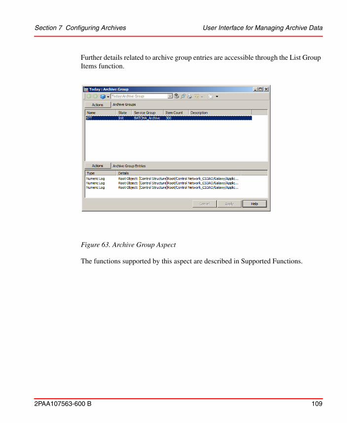
Section 7 Configuring Archives User Interface for Managing Archive Data
2PAA107563-600 B 109
Further details related to archive group entries are accessible through the List Group Items function.
The functions supported by this aspect are described in Supported Functions.
Figure 63. Archive Group Aspect

User Interface for Managing Archive Data Section 7 Configuring Archives
110 2PAA107563-600 B
Supported Functions. The runtime functions supported by this aspect are described in Table 14. All functions are available through the Action button and context menu as shown in Figure 64.
Table 14. Functions Supported by Archive Group Aspect
Field Description
Archiving Logs Manually
An alternative to scheduled archiving.
Resetting the Last Archive Time for an Archive Group
If needed, reset the last archive time to cause the next archive operation to go back farther in time, for example to account for a failed archive, or skip ahead to a later time.
List Group Items Used to determine the exact content of an archive group (items contained within the archive entries).
Figure 64. Archive Group Aspect Context Menu

Section 7 Configuring Archives Maintaining Archive Media
2PAA107563-600 B 111
Maintaining Archive Media
The media where archive data is written will eventually become full and need to be replaced or erased to make room for new archive data. When an archive device is configured, consider generating an alarm message when the media is approaching full capacity. Use a desktop application, such as DataDirect, to read these messages periodically to check the status of the archive media.
MO Media
For MO archive media, the platter must be removed and replaced when it becomes full. The new platter must then be initialized. Refer to:
• Removing/Replacing Platters
• Initializing an Archive Volume
Hard Disk Media
When archiving to a hard disk, it is strongly recommended that an archive backup function be configured. With archive backup, when a volume becomes full, the contents are written to an ISO Image file at a specified location. These files can then be burned onto CD ROM or DVD media for permanent storage. Rather than write ISO image files, specify that a backup copy of the archive be created at the specified location. Both an ISO image and a shadow copy can be created. Once the entries have been saved to a removable media, the hard disk must be periodically purged of old entries to provide space for new entries.
Other Maintenance Operations
This section also covers:
• Activating/Deactivating an Archive Device
• Remounting a Volume
• Copying Volumes
• Overriding Volume Backup
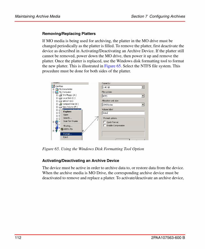
Maintaining Archive Media Section 7 Configuring Archives
112 2PAA107563-600 B
Removing/Replacing Platters
If MO media is being used for archiving, the platter in the MO drive must be changed periodically as the platter is filled. To remove the platter, first deactivate the device as described in Activating/Deactivating an Archive Device. If the platter still cannot be removed, power down the MO drive, then power it up and remove the platter. Once the platter is replaced, use the Windows disk formatting tool to format the new platter. This is illustrated in Figure 65. Select the NTFS file system. This procedure must be done for both sides of the platter.
Activating/Deactivating an Archive Device
The device must be active in order to archive data to, or restore data from the device. When the archive media is MO Drive, the corresponding archive device must be deactivated to remove and replace a platter. To activate/deactivate an archive device,
Figure 65. Using the Windows Disk Formatting Tool Option

Section 7 Configuring Archives Maintaining Archive Media
2PAA107563-600 B 113
go to the Archive Device aspect main view, click Actions and choose Activate or Deactivate as shown in Figure 66.
Remounting a Volume
Volumes should be remounted prior to initializing. A volume may also be remounted to refresh the volume information on the archive device aspect. Remounting is performed through the archive device aspect. To remount a volume, select the volume on the archive device aspect, right click and choose Remount from the context menu as shown in Figure 67.
Initializing an Archive Volume
Each new archive volume must be initialized prior to archiving data on it. For scheduled archives, volumes are automatically initialized if the device behavior is
Figure 66. Activating an Archive Device
Figure 67. Remounting a Volume

Maintaining Archive Media Section 7 Configuring Archives
114 2PAA107563-600 B
set to Advance When Full or Wrap When Full. For manual archives, the volume must be manually initialized.
Initialization of archive volumes may be done using the archive device aspect for the archive device whose volume needs to be initialized, or the archive volume aspect may be used.
To initialize a volume:
1. Install the archive media in the disk drive.
2. Navigate to and select either the archive device aspect whose volume is being initialized, or select the applicable archive volume aspect.
3. If the archive volume aspect is being used, invoke the Initialize command from the Action button or context menu as shown in Figure 68, then skip steps 4 and 5 which pertain only when using the archive device aspect. Resume the procedure at Step 6.
Figure 68. Initializing a Volume From the Archive Volume Aspect
For MO drives, before the archive volume is initialized, make sure the media has been formatted as described in Removing/Replacing Platters on page 110 .

Section 7 Configuring Archives Maintaining Archive Media
2PAA107563-600 B 115
4. If the archive device aspect is being used, select and remount the volume. This is not required when using the archive volume aspect.
Always remount a volume BEFORE initializing it from the archive device aspect. The information in the archive device aspect is not automatically updated when a new archive media is inserted, and so may not accurately indicate the current Contents of the archive device. Remounting the volume will ensure that the selected volume is actually installed in the archive device. To do this, select the volume, right click and choose Remount from the context menu (Remounting a Volume on page 112).
5. If the archive device aspect is being used, once the volume has been remounted, re-select the volume, right click and choose Initialize from the context menu as shown in Figure 69.
Figure 69. Initializing the Selected Volume
6. Whether the archive volume aspect or the archive device aspect is being used, invoking the Initialize command displays the Initialize Volume dialog as shown in Figure 70.
Figure 70. Initialize Archive Media Window

Maintaining Archive Media Section 7 Configuring Archives
116 2PAA107563-600 B
The Volume ID and Overwrite Timeout default to the values specified for all volumes on the archive device config view. Use this dialog to change these values if necessary. As an option, enter a Volume Label. For further details regarding these initialization parameters refer to Table 15.
7. Click OK to initialize the media. If the initialization parameters are specified correctly, a message indicating the initialization was successful appears in the message box, and the Volume State will go to Valid as shown in Figure 71. If one or more parameters were defined incorrectly, an error message appears. If
Table 15. Initializing Archive Media
Field Description
Overwrite Timeout This defaults to the Overwrite Timeout as configured in the Archive Device aspect’s config view. The Overwrite Timeout specifies the delay between the time when a media becomes full and the time when the media can be re-initialized
(overwritten).
Set this to the duration for which the data must be preserved. For example, if data must be preserved for one year, set the Overwrite Timeout to 365 days. This means 365 days after the LAST data has been written to the media, the media
can be automatically initialized by archival if the media is in the drive. Select a unit (Days, Hours, Minutes, Seconds), and then specify the number of units, for example: 365 Days.
The Overwrite Timeout is stored on the media, so removing the media from the drive for a period of time and then replacing it will not affect the Overwrite Timeout.
Volume ID This is a name assigned to this specific volume. The format was specified when the archive device was configured.
Volume ID Evaluated When a formatted string is entered in the Volume ID field, the format characters are replaced with corresponding values in this field. The # signs will be replaced by the configured next label when the media is actually initialized.
Volume Label This is an optional descriptor to further identify the media.

Section 7 Configuring Archives Maintaining Archive Media
2PAA107563-600 B 117
the Overwrite Timeout has not expired on the media being initialized, then verify whether or not to overwrite it.
Figure 71. Initialize Successful Volume
Copying Volumes
Archive devices can be configured to automatically create shadow copies and/or ISO images of archive volumes when those volumes become full. The Copy Volume function is used to perform these functions on-demand. This function is available on the Archive Volume aspect. Click the Action button and choose Copy Volume.

Maintaining Archive Media Section 7 Configuring Archives
118 2PAA107563-600 B
This displays the Copy Volume dialog, Figure 72. Use this dialog to specify the copy volume parameters as described in Table 16. Click OK when done.
Figure 72. Copy Volume Dialog
Table 16. Copy Volume Specification
Field Description
Source Volume ID Automatically filled in based on the volume whose aspect is selected.
Destination Volume ID Enter the Volume ID for the new copy. This is typically the same as the Source Volume ID.
Destination Path Enter the full path to the location (drive\folder\folder...) where the copy will be created.
Destination Volume Label
Used to specify a new volume label. The default is to use the label of the volume being copied.
Overwrite Timeout Used to specify a new overwrite timeout. The default is to use the overwrite timeout of the volume being copied.
Include Archives Used to specify the range of archive entries to copy.

Section 7 Configuring Archives Archiving Logs Manually
2PAA107563-600 B 119
Overriding Volume Backup
When archive backup is configured, volumes are marked as backed up whenever a volume backup is successful. This indicates that the volume may be overwritten. The archive service will not overwrite any volume that is not marked as backed up.
This function is used to mark a volume as backed up, whether or not the volume actually has been backed up.
To override a volume backup, go to the Archive Device aspect main view, click Actions and choose Override Volume Backup. This displays a warning message. Click Yes to continue or No (or Cancel) to cancel.
Archiving Logs Manually
Typically, archiving is configured to occur periodically according to schedules configured through the Application Scheduler. A manual (on-demand) archive may
Destination Quota Used to specify a new quota. The default is to use the quota of the volume being copied. The value is entered in megabytes (MB).
Temporary Storage path
Overwrite Destination This check box is used to specify whether or not to overwrite the current contents of the specified destination. Checking this box will allow the contents of the destination directory to be overwritten.
Create ISO Image Checking this check box will create an ISO Image in addition to the shadow copy in the specified destination.
Do Not Verify Signatures
Used to specify whether or not to verify signatures. If signatures are verified, the volume will not be copied if signatures are not verified.
Preserve Init Time This check box is used to specify whether or not to preserve the initialization time stamp. Checking this box will preserve the time stamp.
Table 16. Copy Volume Specification (Continued)
Field Description

Archiving Logs Manually Section 7 Configuring Archives
120 2PAA107563-600 B
also be performed. For manual archives, if the specified time range has no samples, no data will be archived. Perform the following method to perform manual archive:
• Perform a manual archive of an archive group. This functionality is supported by the Archive Group aspect.
Manual Archiving for Archive Groups
This procedure is done using the archive group aspect. This aspect provides a list of all archive groups configured within the system. Other functions supported by this aspect that may be useful for archiving on a group basis are:
• List Group Items
• Resetting the Last Archive Time for an Archive Group
To perform a manual archive of an archive group:
1. Select the Archive Group whose entries are to be manually archived, then right click and choose Manual Archive from the context menu as shown in Figure 73.
Figure 73. Selecting the Archive Group

Section 7 Configuring Archives Making Archived Data Available to Client Applications
2PAA107563-600 B 121
This displays the Manual Archive dialog as shown in Figure 74.
2. Specify the manual archive settings as described in Table 17.
Table 17. Manual Archive Settings
Parameter Description
Device Archive device to process the archive entry.
Volume Volume on selected archive device where archive entry will be written.
Start and End Times
Time span for data to be archived.
Description Optional description to label the archive entry
Making Archived Data Available to Client Applications
Publish the archived data in order to view the same in an external application such as DataDirect.
Publishing an Archive Volume
The contents of one or more archive volumes can be published to let client applications such as DataDirect access the archived data.
Figure 74. Manual Archive Dialog

Making Archived Data Available to Client Applications Section 7 Configuring Archives
122 2PAA107563-600 B
Publishing reads the information needed to locate the archive entries from the archive volume and copies the information to media database files located in the directory pointed to by the HS_TMP environment variable. When a request for published archive data occurs, History uses this media database to find the requested data.
The contents of a complete volume, or even multiple volumes can be published in relatively few steps.
This procedure may be performed through either an archive device aspect, Figure 75, or an archive volume aspect, Figure 76.
Archive device aspects are typically located in the Node Administration structure, under the Industrial IT Archive container for a selected node as shown in Figure 75. Select the volume to be published, then right-click and choose Publish from the context menu.
The media database files require a certain amount of free disk space on the hard drive. Un-publish any volumes that are not being accessed on a regular basis to limit the size of the media database.

Section 7 Configuring Archives Making Archived Data Available to Client Applications
2PAA107563-600 B 123
Archive volume aspects are typically located in the Node Administration structure, under their respective archive device aspects. When using an archive volume aspect, the Publish command is available through the Action button, Figure 76.
Completion of the publish operation is indicated by a Success message in the status window as shown in Figure 77.
Figure 75. Publishing a Volume from the Archive Device Aspect
Archive entries written to the volume after publishing will not be in the media database. Access to this data would require the volume to be unpublished and then republished.
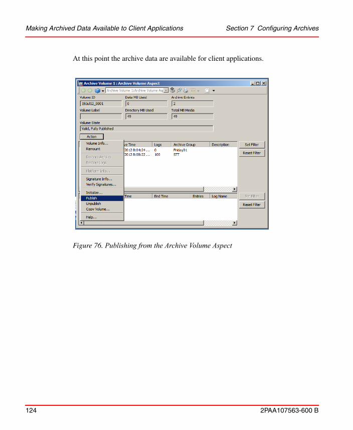
Making Archived Data Available to Client Applications Section 7 Configuring Archives
124 2PAA107563-600 B
At this point the archive data are available for client applications.
Figure 76. Publishing from the Archive Volume Aspect

Section 7 Configuring Archives Making Archived Data Available to Client Applications
2PAA107563-600 B 125
Accessing Published Logs
Published logs can be accessed by external applications such as DataDirect as easily as runtime logs. The only difference is that the full log name must be used, and the -r suffix must be used in place of the -o suffix to distinguish between original (runtime) and published logs.
Un-publishing a Volume
The media database files are pre-allocated to a certain size. When there is not enough room in the files to publish another volume, the files will increase in size. Un-publishing a volume makes the file space used by that volume available for other volumes to be published in the future. Therefore, unpublish a volume when it is finished. To do this:
1. Select the volume as described in Publishing an Archive Volume.
Figure 77. Success Message

Making Archived Data Available to Client Applications Section 7 Configuring Archives
126 2PAA107563-600 B
2. Right-click and choose Unpublish Volume from the context menu.
Unpublishing a volume does not decrease the size of the media database files. To recover disk space, these files may be deleted. The files are located in the directory pointed to by the HS_TMP environment variable. Unpublish all published volumes before deleting the media database files.
Figure 78. Unpublishing a Volume

2PAA107563-600 B 127
Appendix A IP Address Change
IntroductionThis section details the procedure for changing the IP Address of History Embedded Data Collector Node and History Server.
History Embedded Data Collector NodesThe detection of the change in IP Address in DCN is automatic.
In case of DCN node containing multiple IP Addresses, the primary one that is used by the IP stack for History Server communication is used.
Steps to be performed on History Embedded Data Collector Nodes:
1. Change the IP Address of the DCN.
2. If NAT (Network Address Translation) is applied in router between DCN and History Server, follow Step a else continue with Step 3.
When NAT is applied in the router between the DCN and History Server, the applicable IP address to be used for connecting to the DCN from History Server should be defined by using a configuration parameter P_MYIPFORMAIN. This parameter needs to be defined manually:
a. In DCN computer, go to Start > Run and type notepad %app_root%\setup\app_query_configuration_getparameter_P_MYIPFORMAIN.bat.
b. Click Yes to create a new file.
c. Type the following in the opened file:
@echo "P_MYIPFORMAIN=IP_Address_of_DCN"

800xA History Server Appendix A IP Address Change
128 2PAA107563-600 B
In IP_Address_of_DCN enter the new IP Address of DCN.
For example,
@echo "P_MYIPFORMAIN=192.168.0.1"
d. Save and close the document.
3. Activate the Post-Install script:
a. Open windows service control manager from Control Panel > Systems and Security > Administrative Tools > Services.
b. Navigate to RTDB-Scheduler X:\RTDBData Service (where X is the database drive name).
c. Right-click and select Restart to restart the RTDB-Scheduler service.
Verification:
1. After performing above the steps, open Vtrin GUI. Navigate to Maintenance > Basic > Database Nodes.
2. The Database Nodes entry in both DCN and in the History Server should contain the updated IP address for the DCN.
3. The latest diagnostic log file in DCN:
%app_datapath%\diag\APP_PostInstall_HierarchicalCpmPlusKM_yyyy-mm-dd.log should contain an entry:
INFO: telling MAIN my new IP address "xxx", old was "xxx"
The Post-Install script in History Server side is activated automatically. It will use the new IP address information of DCN, and configures the necessary files and automatically restarts the corresponding services.
800xA History ServerSince the IP address of History Server must be given during DCN setup phase, the situation when the IP address of History Server changes requires operation in all DCN nodes.
For Standalone History Server, perform the following steps:
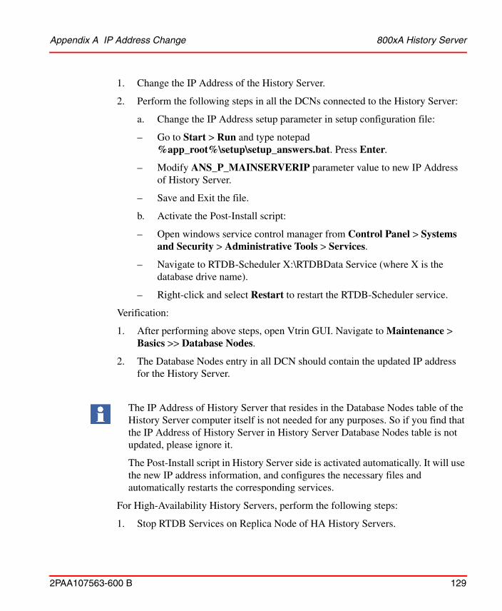
Appendix A IP Address Change 800xA History Server
2PAA107563-600 B 129
1. Change the IP Address of the History Server.
2. Perform the following steps in all the DCNs connected to the History Server:
a. Change the IP Address setup parameter in setup configuration file:
– Go to Start > Run and type notepad %app_root%\setup\setup_answers.bat. Press Enter.
– Modify ANS_P_MAINSERVERIP parameter value to new IP Address of History Server.
– Save and Exit the file.
b. Activate the Post-Install script:
– Open windows service control manager from Control Panel > Systems and Security > Administrative Tools > Services.
– Navigate to RTDB-Scheduler X:\RTDBData Service (where X is the database drive name).
– Right-click and select Restart to restart the RTDB-Scheduler service.
Verification:
1. After performing above steps, open Vtrin GUI. Navigate to Maintenance > Basics >> Database Nodes.
2. The Database Nodes entry in all DCN should contain the updated IP address for the History Server.
For High-Availability History Servers, perform the following steps:
1. Stop RTDB Services on Replica Node of HA History Servers.
The IP Address of History Server that resides in the Database Nodes table of the History Server computer itself is not needed for any purposes. So if you find that the IP Address of History Server in History Server Database Nodes table is not updated, please ignore it.
The Post-Install script in History Server side is activated automatically. It will use the new IP address information, and configures the necessary files and automatically restarts the corresponding services.

800xA History Server Appendix A IP Address Change
130 2PAA107563-600 B
2. Stop RTDB Services on First node of HA Servers. Before stopping RTDB Services on First node, make sure that all the RTDB Services on Replica Node are stopped.
3. Perform this step if the IP address of network adapters is being changed.
a. Open Network Load Balancing Manager. Make note of Common Name (Full Internet Name) and Common IP (Cluster IP). Use Menu options and Delete Hosts and cluster on both HA Servers.
b. Change the IP Address of the network adapters on both HA Servers that are configured with NLB.
If the HA History Servers are in Domain Environment, then make sure to re-register the History Server(s) at Domain.
c. Reconfigure NLB with the same Common Name and Common IP that previously existed before changing the IP Address, on both HA History Servers. Refer to Appendix B Network Load Balancing (NLB) of 2PAA107280-200 800xA History Installation manual for more details.
4. Perform this step if Common IP (Cluster IP) is being changed.
a. Open NLB Manager and update the Common IP.
5. Restart the HA Servers. Restart the First node first and then Replica node.
6. Open Vrin UI and verify that changed IPs are updated in Maintenance > Basics > DatabaseNodes.
The changed cluster IP may not get updated in DatabaseNodes table. This can be ignored.
7. If the Common IP is changed, then perform the following steps in all Data Collectors:
a. Open Setup_Answers file by running the following command in Start > Run dialog.
notepad "%app_root%\setup\setup_answers.bat"
b. setup_answers opens. Modify the rows:
SET "ANS_P_MAINSERVERIP=<OldNLBCommonIP>"
to

Appendix A IP Address Change Change of Consistency Controller Network IP
2PAA107563-600 B 131
SET "ANS_P_MAINSERVERIP=<newNLBCommonIP>"
c. Save and close the file.
d. Open Command Prompt and run the following command to update DatabaseNodes table.
"%app_root%\config\featureinstall\APP_TimedTask_HierarchicalCpmPlusKM_activate_after.bat"
Change of Consistency Controller Network IP
Perform the following steps to change the IP address of Consistency Controller Network (CCN). These steps are applicable for High-Availability (HA) History Server configurations only.
1. Stop RTDB Services on both HA Servers. Stop the Replica Node and then the First Node.
2. In both the HA Servers, change the IP address of the network adapter that was assigned for CCN.
3. On both History Servers, run the following in the command prompt:
%app_root%\setup\APP_Config_CC.bat
The cmd editor shows the previous CCN IP and asks to provide the new CCN IP.
4. Type the new CCN IP and press Enter button.
The update of CCN IP completes and command prompt returns.
5. Restart the HA Servers in the order of First Node and Replica Node.
Figure 79. Command Prompt

Change of Consistency Controller Network IP Appendix A IP Address Change
132 2PAA107563-600 B
6. After restart, open Vtrin UI and navigate to Maintenance > Basics > Service Parameters (SimpleConfig).
7. Verify that the new CCN IP is updated for RTDB_ConsistencyController and RTDB-CVMCServer of both HA Servers.

2PAA107563-600 B 133
Appendix B Calculation using C# Calculation File
IntroductionThis section describes the basic usage of C# Calculations in History.
This section prepares you to create and execute simple calculations such as:
1. a + b = c using current history calculations
2. Calculate time averages from current history
3. Calculate moving averages
4. Create triggering conditions for results and spawn events once condition criteria are met.
Development Environment
Before continuing, you should have the History installed and running on the development machine.
After installing the product a folder named %APP_ROOT%\Calculations\ must be present where, %APP_DATA% environment variable refers to, for example, <DataBase Drive>:\Application folder depending on the installation parameters.
The intended audience is expected to have basic knowledge of Historian Software and usage of Vtrin user interface. Also basic understanding of Microsoft C# programming language and usage of Microsoft Visual Studio.

Creating Simple Calculation Appendix B Calculation using C# Calculation File
134 2PAA107563-600 B
Creating Simple Calculation
Installing RTDB-CalcScheduler
By default, RTDB-CalcScheduler is not installed with History. This is installed by running the bat file: %APP_ROOT%\Calculations\install\APP_Install_CalcScheduler_Calc.bat from the command line.
A new service RTDB-CalcScheduler will be visible in the Windows services (services.msc). The setup also installs the service to startup along with other RTDB services. RTDB main service starts up the RTDB-CalcScheduler within a minute and runs as a Windows service.
Creating Calculation Module and Task Definitions
Calculation tasks can be created by using Vtrin user interface or ODBC connection and SQL scripts. Here both alternatives are presented as Vtrin, which is more intuitive to use but SQL is suggested when a bulk load that can be automatized is preferred. This also allows skipping phases by just running associated bat files.
To create calculation module, do the following:
1. Create a list of calculation task.
For example, in Figure 80, under User’s Definitions > Calculation examples folder is created followed with Calculations tasks creation. When Calculation tasks list is created, right click the actual list view to select the associated class where the Vtrin loads the data.

Appendix B Calculation using C# Calculation File Creating Calculation Module and Task Definitions
2PAA107563-600 B 135
2. Click OK and press Ctrl+S to save the settings in the list view. This results in
the displaying the no calculation tasks as shown in Figure 81.
Figure 80. Calculation task properties

Creating Calculation Module and Task Definitions Appendix B Calculation using C# Calculation File
136 2PAA107563-600 B
3. Similarly, create list displays for Calculation Modules (Vtrin class
CalculationModule) and for Calculation task states (Vtrin class CalculatioTaskState).
4. After creating the above displays, the tree structure appears as shown in Figure 82.
Figure 81. Calculation tasks

Appendix B Calculation using C# Calculation File Creating Calculation Module and Task Definitions
2PAA107563-600 B 137
To execute four simple calculations a Calculation Module that executes the calculation and one Calculation Task must be created.
1. Select Calculation Modules list and select Edit > New.
2. Specify the name and assembly path. Calculation Modules appears as shown in Figure 83.
For example,
– Name - CalculationExample1
– Assembly - %APP_ROOT%\bin\APP_CalculationExample1.dll
Figure 82. Calculation tasks, modules and task states created

Creating Test Variables Appendix B Calculation using C# Calculation File
138 2PAA107563-600 B
3. To create a new calculation task, do the following:
a. Select the newly Calculation Module and select Edit > New.
b. Specify the properties. Refer Table 19.
Creating Test Variables
In order to run the calculations, certain test variables must be created. This is done by using Vtrin user interface and Variable list view. For example, the following bat file is executed to create consistent names.
%APP_ROOT%\Calculations\APP_CalculationExamples\APP_CalculationExample\CreateTestVariables.bat
Figure 83. Calculation module configuration created

Appendix B Calculation using C# Calculation File Generating Base Class
2PAA107563-600 B 139
The variable available in History and Vtrin can be used to monitor values as shown in Figure 84.
Generating Base Class
To create calculations, base class must be generated. The generated base class is then extended in actual calculation code. The base class makes it easy to refer the currently existing variables and process history data. This results in easy calculation program to develop and maintain.
The base class is generated by using RTDB_CalcGenerator. To generate the base class run the following .bat file in the command line.
RTDB_CalcGenerator -b "%APP_DATAPATH%" -cb
"%APP_ROOT%\bin\RTDB_CalcBase.dll" -bs
"%APP_ROOT%\src\Calculations\RTDB_CalcBase.cs
The last parameter -bs (-baseclasssource) is optional and can be used to dump the base class sources.
Figure 84. Calculation variables created for CalculationExample1

Variable Sections for Calculations Appendix B Calculation using C# Calculation File
140 2PAA107563-600 B
Special Cases
Total variable count is >64000
The current .NET CLR implementation allows only 65536 member fields per class (1534 fields are reserved for other base class functionality). Hence there are only 64000 member fields available. So, it is required to define the Sections of Variables to separate the variables in the different groups with total number of variables not exceeding 64000 per group.
Variable Sections for Calculations
In case of high availability systems perform the following steps on one of the high availability servers.
It is necessary to modify the definition in SimpleConfig for RTDB-Calculation section.
Section: RTDB-Calculation
Key: UseVariableSections
Value(To be Modified):Non-Zero Value(By default it is '0')
1. To modify, do the following:
a. Open Vtrin user interface in one of the History Server.
b. Navigate to Maintenance > Basic > Service Parameters(SimpleConfig).
c. Click Edit tab and navigate to:
Section: RTDB-Calculation
Key: UseVariableSections
d. Click the Value field and enter any non-zero value as shown in Figure 85.

Appendix B Calculation using C# Calculation File Variable Sections for Calculations
2PAA107563-600 B 141
e. Click Revert tab and accept changes.
Define sections for Variable Tables. The idea is to define a section with Maximum 64000 or less Variables. Since the definition of the Section can be trivial, following example explains how to generate variable sections.
Example 1: Defining sections on the basis of Variable Names:praotstx "%APP_DSN%" -sql "update variables set section='System' where variablename like 'SYS_%'"
Example 2: Defining Sections on the basis of Variable Id:praotstx "%APP_DSN%" -sql "update variables set section='System' where VariableId > 70000"
To check the number of variables for the defined section, run the following command:praotstx %app_dsn% -sql "select count(*) from variables where section like 'System'"
Figure 85. Service Parameters(SimpleConfig)

Variable Sections for Calculations Appendix B Calculation using C# Calculation File
142 2PAA107563-600 B
1. After performing the above steps, generate the base class run (as single command line):
RTDB_CalcGenerator -b "%APP_DATAPATH%" -cb
"%APP_ROOT%\bin\RTDB_CalcBase.dll" -bs
"%APP_ROOT%\src\Calculations\RTDB_CalcBase.cs"
Variables with Section other than empty string (''), will be presented in the calculation class as sSectionName.vVariableName.
2. After running the command, the RTDB_CalcBase.dll must be available in the folder "%APP_ROOT%\bin\.
Visual Studio 2012 templates for creating actual calculation modules are located in:
%APP_ROOT%\Calculations\APP_Calculations
APP_Calculations.sln can be taken as the starting point to create new calculation modules. The examples are explained as follows to demonstrate simple calculations. It is located int:
%APP_ROOT%\Calculations\APP_CalculationExamples
Open the solution APP_CalculationExamples.sln by double clicking the solution file.
Four different calculation scenarios are demonstrated:
1. Calculate a + b = c using current history calculation. Justify why calculations are usually done using historical data and not using current values.
2. When temperature is continuously measured, calculate average temperature over each day every Monday 01:00 for last week.
3. When temperature is continuously measured, calculate average temperature over 5 days every night 01:00 (moving average).
4. When temperature is continuously measured, calculate average temperature every night 01:00 for every day. Once for five last days the average daily temperature is below 10 C, create an event that "thermal autumn" has started. This is a definition of "thermal autumn".

Appendix B Calculation using C# Calculation File Variable Sections for Calculations
2PAA107563-600 B 143
Calculating c=a+b every 10 seconds
This example demonstrates the calculation of sum of two values and writing the result in a third variable. Variables used are:
• MyCalcExCurHist_A
• MyCalcExCurHist_B
• MyCalcExCurHist_C
Figure 87 demonstrates the CalculationTask parameters that must be used to create this calculation and also clarifies the meaning of each parameter in CalculationTask declaration.
• ScheduleInterval and ScheduleIntervalUnit properties define when the calculation is executed. These are interpreted against ScheduleBaseTime.
• The PeriodLength and PeriodLengthUnit define the sampling period for the calculations.
• PeriodCount defines how many Periods are calculated in one scheduled calculation.
• Offset defines how calculation period is actually aligned respect to wall clock time or UTC time and respect to the base time defined using the property BaseTime. Offset as well defines what the time stamps of calculation result are. Many times the best timestamp for actual result is the start time of the calculated period.
To produce values for variables MyCalcExCurHist_A and MyCalcExCurHist_B the Vtrin user interface is used to feed values. Open All Variables list and double click the variables to continuously monitor the values as shown in .
After this the process of demonstrating the behavior is accelerated by mapping days to minutes. One day is actually one minute in the examples.

Variable Sections for Calculations Appendix B Calculation using C# Calculation File
144 2PAA107563-600 B
Figure 87 illustrates how different calculation task properties are used to solve first exercise. The actual calculation task can be created bu using Vtrin or using following batch file.
%APP_ROOT%\Calculations\APP_CalculationExamples\APP_CalculationExample\CreateCalculationTask_A_plus_B_CurrentHistory.bat
Figure 86. Monitoring calculation variables using Vtrin variables and current values

Appendix B Calculation using C# Calculation File Variable Sections for Calculations
2PAA107563-600 B 145
Figure 87. Calculating sum of two historical values every 10 seconds

Variable Sections for Calculations Appendix B Calculation using C# Calculation File
146 2PAA107563-600 B
Figure 88. Configuring first calculation using Vtrin

Appendix B Calculation using C# Calculation File Variable Sections for Calculations
2PAA107563-600 B 147
Daily average calculated once a week
Figure 89. Daily averages calculated once a week

Variable Sections for Calculations Appendix B Calculation using C# Calculation File
148 2PAA107563-600 B
Moving average
Calculating daily average and triggering event when condition applies for 5 continuous periods
In this previous example it is demonstrated how to observe the beginning of "Thermal autumn". Thermal autumn is defined to begin when "Daily average of temperature" has not exceeded 10°C for five days. Here it is assumed that starting date would be the end of the 5 days period rather than beginning of the 5 days period. More formally
MAX(5Days) {AVG(1Days){temperature}} < 10°C
This should be evaluated each day for last five days to observe the event as soon as possible.
Figure 90. Moving average over 5 days calculated every night

Appendix B Calculation using C# Calculation File Variable Sections for Calculations
2PAA107563-600 B 149
Diagnostics
For diagnostics purposes there is a class CalculationTaskState. It shows the last execution time and as well when the task is to be run next time. If errors are available these are displayed as well (). For elaborated application specific diagnostics full C# support is available.
Figure 91. Calculating daily averages after every day to be able to notice when thermal autumn begins

Variable Sections for Calculations Appendix B Calculation using C# Calculation File
150 2PAA107563-600 B
Creating own calculation
1. Open Visual Studio 2012.
2. Create a new Visual C# Class Library project.
3. Add following References: RTDB_CalcInterface.dll and RTDB_ CalcBase.dll
4. Use the following skeleton:
using ABB.Data.RTDB.Calculation;namespace ABB.Data.RTDB.EndUser{ public class Calc : ABB.Data.RTDB.EndUser.CalcBase
Figure 92. Monitoring calculation scheduling from Calculation Task States

Appendix B Calculation using C# Calculation File Variable Sections for Calculations
2PAA107563-600 B 151
{ public override void Initialize() {
//Your Initializations comes here. Example below is for current history. DefaultCvhHistory = hCurrentHistory; } public override void Calculate() { //Your Calculation Equations Comes here } }}
5. The variables are accessed using following:
• If Variable Section is used then the variables are accessed with following syntax:sSectionName.vVariableName
• When Variable Section is not used: vVariableName
6. Use standard C# syntax to define calculation equations.
7. Build your calculation solution.
8. Define Calculation Module as shown in Table 18.
Table 18. Calculation Module
Column Description
Name The unique name of the calculation module.
Assembly A full path to the assembly (or assemblies) or C# source file(s) that contain the calculation modules. When defining more than one assembly or source file they are separated with pipes "|". Mixing assemblies and source files is not supported.
References External assembly references needed in the compilation.
9. Define Calculation Task as shown in Table 19.

Variable Sections for Calculations Appendix B Calculation using C# Calculation File
152 2PAA107563-600 B
Table 19. Calculation Task
Column Description
Name The name for the calculation task.
Module Calculation module to be used.
Class The name(s) of the calculation class(es) to be run by this task. More than one class can be defined by separating them with pipes "|". The classes will be run in the order they are defined.
UserParameters User definable parameters that can be accessed in the calculation class using the ParameterProvider "Parameters".
Description A description for the task.
BaseTime The base time is a local time stamp the periods in the calculation task are aligned to. If the Basetime is not defined the default value 2300-01-01 00:00:00 is used. (NOTE: BaseTime does not affect the actual time at which the calculation task is scheduled to run, see ScheduleBaseTime.)
PeriodLength Defines the temporal resolution of the calculation task and is used to determine (with BaseTime) the start times and lengths of calculated periods.
PeriodLengthUnit The time unit of the period length.
Offset Defines the period offset for the calculation task start time as a number of periods. Positive values point forward (to future) and negative values point backwards (to past). For example, if a calculation task with a calculation level of 5 minutes has a start time of 12:00 and the offset is set to -3, the calculated periods start from
11:45 (3 x 5 minutes in the past).

Appendix B Calculation using C# Calculation File Variable Sections for Calculations
2PAA107563-600 B 153
OffsetUnit The time unit of the offset. If left null, Period Length is used as the offset unit.
PeriodCount PeriodCount defines the number of consecutive periods to be calculated in the calculation task.
PeriodCountUnit The time unit of the period count. If left null,
BatchVariable BatchVariable is used when the period length can vary and a special batch variable in a history table determines the period start times.
NOTE: Offset and Periods are supported with period variables, but not OffsetUnit and PeriodsUnit.
BatchHistory Defines the history table which contains the values for the batch variable. This must be defined when BatchVariable is defined.
SchedulerId The scheduler identifier of the RTDB_CalcScheduler service that handles the scheduling of this task.
ScheduleBaseTime The base time of the calculation schedule.
ScheduleInterval The interval of the calculation schedule.
ScheduleIntervalUnit The time unit of the interval.
FollowWallClockTime If true, the calculation schedule will follow wall clock time, instead of UTC time.
SkipMissed If true, skips missed periods when the calculation service has been turned of. If false, all missed periods will be calculated in the next calculation service start.
Disabled If true, the task will not run when the calculation service is started.
Table 19. Calculation Task (Continued)
Column Description

Variable Sections for Calculations Appendix B Calculation using C# Calculation File
154 2PAA107563-600 B
10. Restart RTDBCalcScheduler service.

2PAA107563-600 B 155
Appendix C History Supervision
IntroductionHistory supervision allows the user to view history server status in PPA. This is used to supervise the RTDB services running history server. Also the information related to the tags available in history server is provided in this aspect.
History Supervision AspectThis aspect have two views:
• Main view: This view displays status of some pre-defined properties of History server, like component status and tag statistics from history server. Current connection status with history server will be displayed in this view.
• Config view: This view displays the current Data Collector Node used to connect history server for this aspect. This view is also responsible for getting the history server credential details from the user.
To view history server status, do the following:
1. Go to Service Structure > 800xA History SyncService, Service.
2. In the Aspect View, select History Supervision as shown in Figure 93.

History Supervision Aspect Appendix C History Supervision
156 2PAA107563-600 B
3. Select Config View.
4. Go to Special Configuration tab and configure history server database details as shown in Figure 93.
5. Click Apply.
Figure 93. History Supervision

Appendix C History Supervision History Supervision Aspect
2PAA107563-600 B 157
6. Go back to the Main View to view the history server connected status - connected as shown in Figure 94.
Figure 94. History Supervision - Main View
If the connection fails, go to Config View and check for credentials.

History Supervision Aspect Appendix C History Supervision
158 2PAA107563-600 B
In the event of network disconnection between Data Collector and History Server, the disconnected status gets updated in History Supervision aspect within one hour. If there is no network disconnection between Data Collector and History Server, the status of History Server RTDB Services gets updated within two minutes.

2PAA107563-600 B 159
Appendix D Diagnostic Information for 800xA
Diagnostic Information for 800xA HistoryThe following information is common for 800xA History Embedded Data Collector as well as 800xA History Server Node.
The diagnostic information is written to text files and can be accessed from the following location:
From Desktop, open RTDB Control Panel folder and then navigate to Diagonistics Tools | View Latest Log Files | Diag. Alternatively, Diag folder can also be accessed by clicking Start | Run, typing, %app_datapath%\diag and then pressing Enter.
The Diag folder contains the log files for all the related services of History or DC as well it contains various logs for the runtime processes by the database.
Additionally, the live diagonistic messages can be viewed for the specific services by the running the batch files available at following location: Desktop | RTDB Control Panel | Diagonistic Tools.
Start/Stop History Server DatabaseStarting and Stopping the Database (either in 800xA History Server or the 800xA History Embedded Data Collector Node) can be carried out by various methods. However, it is advised to use the batch file called Start RTDB/ Stop RTDB available in the Desktop in folder Database Control Panel.
Other methods to stop RTDB are:
1. From Service Structure of 800xA Plant Explorer (only for 800xA History Embedded Data Collector Node)
2. From the Windows Services

Starting Database Using Database Control Panel Appendix D Diagnostic Information for 800xA
160 2PAA107563-600 B
Starting Database Using Database Control Panel
To start the database:
1. Double-click the Real Time History Control Panel folder shortcut icon on the desktop. Three folders as shown in Figure 95 will be displayed.
2. Double-click the Start and Stopping folder to open it. The Start RTDB and Stop RTDB batch files will be displayed as shown in Figure 96
Figure 95. Folders in Real Time History Control Panel
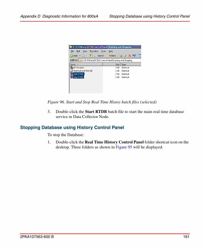
Appendix D Diagnostic Information for 800xA Stopping Database using History Control Panel
2PAA107563-600 B 161
3. Double-click the Start RTDB batch file to start the main real time database
service in Data Collector Node.
Stopping Database using History Control Panel
To stop the Database:
1. Double-click the Real Time History Control Panel folder shortcut icon on the desktop. Three folders as shown in Figure 95 will be displayed.
Figure 96. Start and Stop Real Time Histoy batch files (selected)

Stopping Database using History Control Panel Appendix D Diagnostic Information for 800xA
162 2PAA107563-600 B
2. Double-click the Start and Stopping folder to open it. The Start RTDB and
Stop RTDB batch files will be displayed as shown in Figure 96.
Figure 98. Start and Stop Real Time Histoy batch files (selected)
Figure 97. Folders in Real Time History Control Panel

Appendix D Diagnostic Information for 800xA Start/Stop 800xA History Embedded Data Collector
2PAA107563-600 B 163
3. Double-click the Stop RTDB batch file and type ‘Y’ in the confirmation prompt as shown in Figure 99 to stop the main real time database service in 800xA History Embedded Data Collector Node.
Figure 99. Confirmation Prompt for stopping RTDB
Once the Database stopping process is completed, the system displays the message “RTDB-service has now been stopped. All tables are OK”.
Start/Stop 800xA History Embedded Data Collector Database
To stop the 800xA History Embedded Data Collector database follow one of the methods:
1. Start/Stop the database from the database control panel.
– To start the database from 800xA Service Structure, refer Starting Database Using Database Control Panel.
– To stop the database from 800xA Service Structure, refer Stopping Database using History Control Panel.
2. Start/Stop Database from ABB System 800xA Service Structure.
– To start the database from 800xA Service Structure, refer Starting Database from ABB System 800xA (if installed).

Starting Database from ABB System 800xA (if installed) Appendix D Diagnostic Information for
164 2PAA107563-600 B
– To stop the database from 800xA Service Structure, refer Stopping Database From ABB System 800xA (if installed).
Starting Database from ABB System 800xA (if installed)
1. Double-click the Plant Explorer Workplace icon on the desktop.
2. Click the left side, structure drop-down menu and click Service Structure in the menu item as shown in Figure 100
Figure 100. Service Structure in Plant Explorer Workplace
3. Select 800xA History Embedded Data Collector Sync Service Group in Service Structure through 800xA History SyncService, Service as shown in Figure 101.

Appendix D Diagnostic Information for 800xA Starting Database from ABB System 800xA (if
2PAA107563-600 B 165
4. By default, the Service Group Definition is selected in the right pane as shown
in Figure 102.
Figure 101. Sync Service in Service structure

Starting Database from ABB System 800xA (if installed) Appendix D Diagnostic Information for
166 2PAA107563-600 B
5. Select the 800xA History StatusViewer aspect as shown in Figure 103.
Figure 102. Service Group Definition

Appendix D Diagnostic Information for 800xA Starting Database from ABB System 800xA (if
2PAA107563-600 B 167
6. Click 800xA History Service Manager as shown in Figure 104.
Figure 103. 800xA History Status Viewer
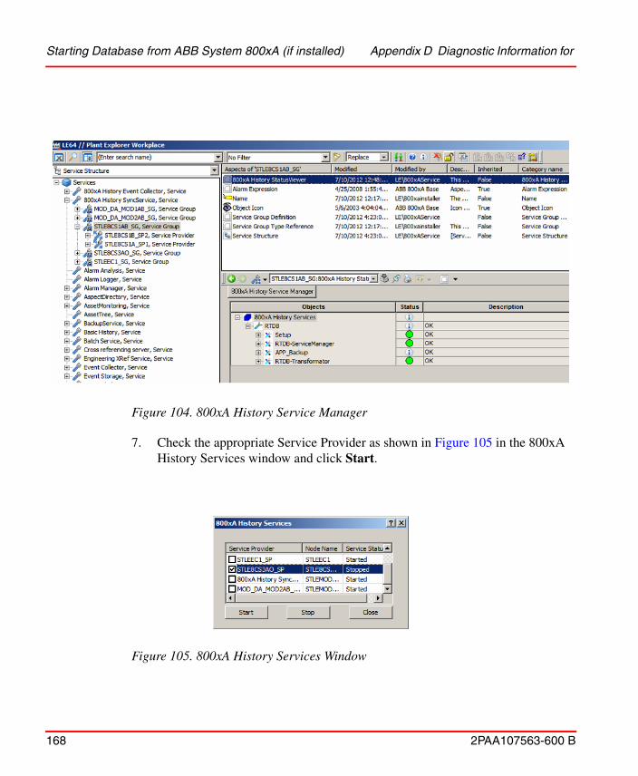
Starting Database from ABB System 800xA (if installed) Appendix D Diagnostic Information for
168 2PAA107563-600 B
7. Check the appropriate Service Provider as shown in Figure 105 in the 800xA
History Services window and click Start.
Figure 104. 800xA History Service Manager
Figure 105. 800xA History Services Window

Appendix D Diagnostic Information for 800xA Stopping Database From ABB System 800xA (if
2PAA107563-600 B 169
Stopping Database From ABB System 800xA (if installed)
1. Double-click the Plant Explorer Workplace icon on the desktop.
2. Click on the left side, structure drop down menu and select Service Structure in the menu item as shown in Figure 100.
3. Select 800xA History Embedded Data Collector Sync Service Group in Service Structure through 800xA History SyncService, Service in the left pane of Service Structure as shown in Figure 101.
4. By default, the Service Group Definition is selected in the right pane as shown in Figure 102
5. Select 800xA History StatusViewer as shown in Figure 103.
6. Click 800xA History Service Manager as shown in Figure 104.
7. Check the appropriate Service Provider in 800xA History Service Manager as shown if Figure 106 and click Stop.
Figure 106. 800xA History Services

Stopping Database From ABB System 800xA (if installed) Appendix D Diagnostic Information for
170 2PAA107563-600 B
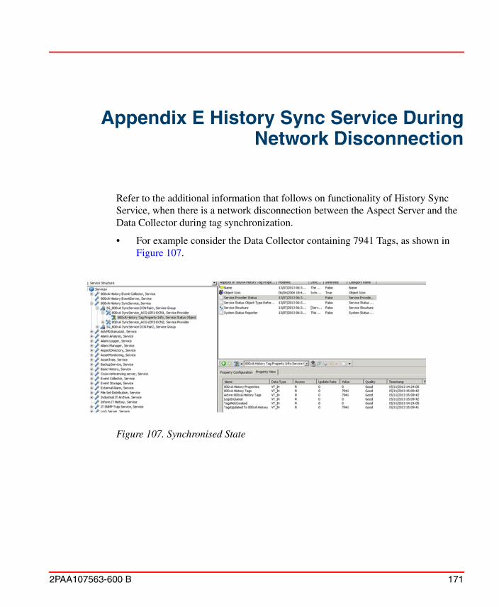
2PAA107563-600 B 171
Appendix E History Sync Service During Network Disconnection
Refer to the additional information that follows on functionality of History Sync Service, when there is a network disconnection between the Aspect Server and the Data Collector during tag synchronization.
• For example consider the Data Collector containing 7941 Tags, as shown in Figure 107.
Figure 107. Synchronised State

Appendix E History Sync Service During Network Disconnection
172 2PAA107563-600 B
• In the event of network disconnection between Aspect Server and Data Collector, the 800xA History Tag Property Info show the status as in Figure 108.
Figure 108. Synchronization Stopped State
• Based on Figure 108, it is important to understand that the tags are not actually deleted, instead, the Sync Service Synchronization is stopped.
• Make sure to fix the disconnected network and restart the 800xA History Sync Service to re-sync with the database and show the correct status in 800xA History Tag Property Info as shown in Figure 107.
Based on the disconnection timing, the Sync can be stopped at any moment. In the example given, the Sync stopped at 800xA History Tags value of 936.

2PAA107563-600 B 173
Appendix F Password Update Procedure
This section describes the steps that have to be followed on the History Server and Data Collector when the Database Admin User Password is changed.
This section does not include the procedure to change the password of the source historian that the Data Collector is collecting from.
Please make sure that the password of the Windows User account, used of Database Admin, is already changed.
Contact Microsoft for the detailed procedure on changing the password of Windows User account.
Password Update Procedure on the History Server:Perform the following steps to update the History Server with the new Password.
1. Login to the History Server with the installation user.
2. Stop the RTDB Services.
3. Navigate to Control Panel > User Accounts > Credential Manager.
4. Edit and Update Generic Credentials with the new password for CPIMS/ADMIN, CPIMS/DBADMIN.
5. Perform the following steps to reinstall the RTDB services.
a. Open a Command Prompt (enter cmd in the Run… dialog) and run the following command to remove the existing services.
"%app_root%\config\application\APP_Install_Services" /remove all
b. Enter "Y" when asked for confirmation.
c. After successful removal, run the following command to install services.

Password Update Procedure on the Data Collector: Appendix F Password Update Procedure
174 2PAA107563-600 B
"%app_root%\config\application\APP_Install_Services" /install all
d. In Windows Services configuration, set the startup type of the RTDB main service RTDB <RTDBDatabaseDrive>:\RTDBData to Automatic.
6. Restart the History Server.
7. Use the installed user credentials and log on to each one of the Data Collectors and perform the following steps:
a. Stop RTDB.
b. Navigate to Control Panel > User Accounts > Credential Manager.
c. Edit and Update the password for CPIMS/MAIN_DBADMIN with the latest password of History Server.
d. Close the Credential Manager.
e. Start the RTDB Services.
f. Open Plant Explorer. Navigate to the Service Structure and update the password of History Server for 800xA History EventServer Service and History Supervision aspect.
Password Update Procedure on the Data Collector:Perform the following steps to update the Data Collector with the new Password.
1. Login to the Data Collector with the installation user.
2. Stop the RTDB Services.
3. Navigate to Control Panel > User Accounts > Credential Manager.
4. Edit and Update Generic Credentials with the new password for CPIMS/ADMIN, CPIMS/DBADMIN.
5. Perform the following steps to reinstall the RTDB services.
a. Open a Command Prompt (enter cmd in the Run… dialog) and run the following command to remove the existing services.
"%app_root%\config\application\APP_Install_Services" /remove all
b. Enter "Y" when asked for confirmation.

Appendix F Password Update Procedure Password Update Procedure on the Data Collector:
2PAA107563-600 B 175
c. After successful removal, run the following command to install services.
"%app_root%\config\application\APP_Install_Services" /install all
d. In Windows Services configuration, set the startup type of the RTDB main service RTDB <RTDBDatabaseDrive>:\RTDBData to Automatic.
6. Login to History Server and open Credential Manager by navigating to Control Panel > User Accounts.
7. Select the Generic Credential corresponding to the Data Collector updated with password (for example, CPIMS_DC/<DCNName>_DBADMIN).
8. Use the Edit option and update the password. Save and close Credential Manager.
9. Start the RTDB services from the Data Collector.
10. Open Plant Explorer. Navigate to Service Structure and update the new password in Special Configuration tabs of 800xA History SyncService, 800xA History Event Collector and 800xA History EventServer Services and restart the services.

Password Update Procedure on the Data Collector: Appendix F Password Update Procedure
176 2PAA107563-600 B
2PAA107563-600 B 177
Appendix G Accessing 800xA History DA Server
Accessing 800xA History DA Server Using DCOM SettingsWhen configuring OPC client to access 800xA History DA Server, ensure that client machine is in Workgroup or Domain Environment.
Refer important information related to DCOM settings required for accessing 800xA History DA server as mentioned below.
Workgroup Environment
In workgroup environment, if the OPC Client PC is in same workgroup as 800xA History DA Server than following should be done.
• There should be a common user account for running both OPC Server and OPC Client.
• If the OPC Server and OPC Client are running with different user account, then, these local user accounts should be available in both PC. For example, if the OPC Server runs with local user account 'A' and OPC Client runs with user account 'B' then both local user 'A' and 'B' should be available in OPC Server (For example, 800xA History Server Node) as well as OPC Client Node. It is not mandatory that these user account have same password.
Ensure to have administrative privileges to create user accounts which are mentioned in the following description.

Domain Environment Appendix G Accessing 800xA History DA Server
178 2PAA107563-600 B
Domain Environment
When the 800xA History DA Server and Client PC are in same domain
Ensure that domain user accounts are used for running the OPC Server as well as OPC Client. So, in this case, no need to create users in each PC (as it is done in workgroup environment.)
When the 800xA History DA Server and Client PC are in different domain
When the 800xA History DA Server and Client PC are in different domain, first, ensure that to setup a 'Trust Relationship' between both domains. Please contact your system administrator for configuring the 'Trust Relationship' between domains.
Workgroup to Domain Environment
This scenario is a little bit complicated as compared to what we have seen in case, when both Server and Client PCs are either in Workgroup or Domain Environment.
Make sure that when one PC is in domain and other is in workgroup is the workgroup cannot authenticate domain user account.
So to make the Workgroup and Domain environment interoperate, ensure to have local user account defined in both Server and Client PC. Following are important points to consider:
• OPC Server must run as a local user account. This local user account should be available in both Server and Client PC with same username and password.
• OPC Client must run as a local user account on the client PC and that same local user account must exist on the OPC Server PC with the same username and password.
Ensure that the user account is set properly for DCOM settings. For example, the username in case of domain user account will be like 'DomainName\Username'. Before doing the DCOM settings, please make sure that both the OPC Server and the OPC Client are running with the same domain user account.
If the local user account is used for DCOM settings, then this user account should be consistent in Server and Client PC.

2PAA107563-600 B 179
Appendix H User Name Update Procedure
User Name Update Procedure on the 800xA History Server and 800xA History DCN nodes
This section describes the steps that have to be followed on the History Server and Data Collector when the Database Admin User Name or DB Admin User Name is changed. This section does not include the procedure to change the user name of the source historian that the Data Collector is collecting from. Please make sure that the New User name of the Windows User account, used for Database Admin, is already created. Contact Microsoft for the detailed procedure on creating the Windows User account.
Instructions for Changing the Admin user
Follow the steps below to update the History Server with the new User name.
1. Log on with the user account that was originally used for installing RTDB.
2. Stop RTDB
3. Modify the name and password of the new account to the Windows vault entry “CPIMS/ADMIN”
Navigate to Control Panel > User Accounts > Credential Manager
4. Add the user to the RTDB-Admin group by running:
“%app_root%\Config\Security\APP_Create_users.bat”
5. Reinstall the services
a. “%app_root%\config\application\APP_Install_Services” /remove all
b. “%app_root%\config\application\APP_Install_Services” /install all
c. Set the startup type of RTDB main service back to Automatic

Instructions for Changing the DB Admin User Appendix H User Name Update Procedure
180 2PAA107563-600 B
6. Start RTDB
7. If this was the 800xA History Server node, force re-registration of the DCN nodes (this is needed that the new adminuser will know the access information to the DCN nodes)
a. praotstx %app_dsn% -sql "delete from simpleconfig where sectionname like 'DatabaseNodes_%' and KeyName like 'Added_%'"
b. Restart RTDB-Scheduler in all 800XA History DCN nodes
8. Recommendation: clean up the Vault entries for the old adminuser
The names of the vault entries start with "CPIMS/" or "CPIMS_DC/"
Instructions for Changing the DB Admin User
1. Log on with the user account that was originally used for installing RTDB
2. Store the name and password of the new account to the Windows vault entry "CPIMS/DBADMIN" by navigating to Control Panel > User Accounts > Credential Manager
3. Add the user to the RTDB-Admin group by running:
"%app_root%\Config\Security\APP_Create_users.bat"
4. If this was the 800xA History Server node, you need to tell the new user name and password to each data collector node:
a. Log on to the data collector node with the user account that was originally used for installing RTDB
b. Update the vault information for entry "CPIMS/MAIN_DBADMIN"
Navigate to Control Panel > User Accounts > Credential Manager
c. Run the below command: %app_root%\config\featureinstall\APP_Give_Setup_Answers_to_adminuser.bat
This step is optional if the logged on user is the adminuser

Appendix H User Name Update Procedure Instructions for Changing the DB Admin User
2PAA107563-600 B 181
5. If this was a DCN node, force re-registration of the DCN node to the main node:
a. In the main node: praotstx %app_dsn% -sql "delete from simpleconfig where sectionname like 'DatabaseNodes_%' and KeyName like 'Added_NN'"
NN is the name of the DCN node
b. In the DCN node: restart RTDB-Scheduler

Instructions for Changing the DB Admin User Appendix H User Name Update Procedure
182 2PAA107563-600 B

2PAA107563-600 B 183
Revision History
The following table lists the revision history of this User Manual.
Updates in Revision Index AThe following table shows the updates made in this User Manual for System 800xA 6.0:
The revision index of this User Manual is not related to the 800xA 6.0 System Revision.
Revision Index
Description Date
- Published for 800xA System Version 6.0. Octoberr 2014
A Published for 800xA System Version 6.0. December 2014
B Published for 800xA System Version 6.0.1. October 2015
Updated Section/Sub-section Description of Update
Appendix F Steps 6, 7, 8, 9 and 10 have been updated in “Password Update Procedure on the Data Collector”.

Updates in Revision Index B
184 2PAA107563-600 B
Updates in Revision Index BThe following table shows the updates made in this User Manual for System 800xA 6.0.1:
Updated Section/Sub-section Description of Update
Appendix H Added the User Name Update Procedure

Index
2PAA107563-600 B 185
AActive Volume, Archive Device 87Archive
backup configuration 88Functions 79Media 79, 81Volumes 80
Archive DeviceAttributes 84Configuration 81
Archive Group 90Archive Group Entry Options 95Archive Path, Archive Device 85Archive Service Aspect 82Aspect
Archive Device 84Archive Group 92Archive Service 82
auto-publish, volume 87
BBackup Archive Path, Archive Device 89Backup Disk Utilization Warning 90Backup Type, Archive Device 89
CConfiguring
3rd party OPC AE Server with RTDB 30Using Vtrin 17
Configuring Excel Data Source 49Copy Files, Backup Type 89Create Auto-Published Volume 87
DDCOM Settings for Accessing History DA Server
47Device Behavior, Archive Device 86Device Type, Archive Device 85Diagnostic Information for 800xA History 159
Diagnostic Information for History 55Domain Environment 48
EEnvironment
Domain 178Workgroup 177Workgroup-Domain 178
HHistory 13History Embedded Data Collector 15History Features 14History Server 15
IISO Image, Backup Type 89
LLocal Disk Utilization Warning 90
MMagnetic/Optical (MO) disk 79
Nname counter, volume 87name format, volume 87
OODBC Interface 49OPC DA 42OPC HDA 44, 46OPC Interfaces 41Overwrite Timeout, Archive Device 86
QQuota, Volume 87
Index

Index
186 2PAA107563-600 B
Index
Sshadow copy, backup method 89Start 58Start History Server Database 55Start/Stop History Server Database 159Starting Database
Using Database Control Panel 160Stop History Embedded Data Collector Database 58Stop History Server Database 55Supervision 155, 177
TTag Synchronization 65
UUtilization Warning, Archive Device 90
VViewing
Numeric Data 34Viewing Events by Specific Time and Date 40Viewing Events Data 39Viewing Events on Duration Basis 39Volume Name Counter, Archive Device 87Volume Name Format, Archive Device 87Volume Quota, Archive Device 87Volumes, Archive Device 87
WWorkgroup Environment 48Workgroup to Domain Environment 49


Power and productivity for a better worldTM
Contact us
Copyright © 2015 ABB.All rights reserved.
2PA
A10
7563
-600
Bwww.abb.com/800xAwww.abb.com/controlsystems