synthesis and catalytic performance of metal …
TRANSCRIPT

Thesis for obtaining a title of Doctor of Chemical Engineering of Federal University of Rio
Grande do Sul a title of Doctor of Université de Lille
Specialty: Organic, Mineral and Industrial Chemistry
Molecules and Condensed Matter
SYNTHESIS AND CATALYTIC
PERFORMANCE OF METAL-ZEOLITE
COMPOSITE CATALYSTS
by Camila Gomes Flores
Thesis Supervisors: Prof. Dr. Nilson Romeu Marcilio (UFRGS, Porto Alegre, Brazil) Dr Andrei Khodakov, CNRS Research Director (UCCS, Université de Lille, France)
The PhD thesis defense took place on April 29th, 2019 in UFRGS, Porto
Alegre, Brazil
PANEL OF EXPERT EXAMINERS: Reviewer Dr Benoît Louis, DR CNRS, Université de Strasbourg (France) Reviewer Professor Juliana da Silveira Espindola, Federal University of Rio Grande (Brazil) Dr Cuong Pham-Huu, DR CNRS, Université de Strasbourg (France) Professor Márcio Schwaab, Federal University of Rio Grande do Sul (Brazil) Professor Nilson R. Marcilio, Federal University of Rio Grande do Sul (Brazil) Dr Andrei Khodakov, DR CNRS, Université de Lille (France)

ii
CONTENTS
TABLE LIST ......................................................................................................... iv
FIGURE LIST ......................................................................................................... v
ABSTRACT ......................................................................................................... viii
RESUMO ................................................................................................................ x
RESUMÉ .............................................................................................................. xii
Chapter 1: Introduction ........................................................................................... 14
1.1 Challenges in the design of bifunctional catalysts and goals of the thesis ........... 15
Chapter 2: Literature Review ................................................................................. 18
2.1 Zeolites: structure, porosity, acidity and catalysis ................................... 18
2.2 Reactions occurring on metal-zeolite catalysts ........................................ 29
2.2.1 Model reactions on acid sites ................................................................ 29
2.2.2 Model reactions on metal sites ............................................................. 32
2.2.3 Fischer-Tropsch Synthesis .................................................................... 33
2.2.4 Catalysts ................................................................................................ 39
References ............................................................................................................. 40
Chapter 3: Influence of impregnation and ion exchange sequence on metal
localization, acidity and catalytic performance of cobalt zeolite catalysts in Fischer-
Tropsch synthesis ........................................................................................................ 52
3.1 Introduction .............................................................................................. 52
3.2 Experimental Section ............................................................................... 55
3.3 Results and Discussion ............................................................................ 57
3.4 Conclusion ............................................................................................... 70
References ...................................................................................................... 71
Supporting Information ................................................................................. 74

iii
Chapter 4: Direct production of iso-paraffins from syngas over hierarchical cobalt-
ZSM-5 nanocomposites synthetized using carbon nanotubes as sacrificial templates 76
4.1 Introduction .............................................................................................. 76
4.2 Experimental Section ............................................................................... 79
4.3 Results and Discussion ............................................................................ 84
4.4 Conclusion ............................................................................................... 97
References ...................................................................................................... 99
Supporting Information ............................................................................... 102
Chapter 5: Multifaceted Role of Metal Carbon Nanotube Templates in the Synthesis
of Hierarchical Zeolite Composite Catalysts ............................................................ 107
5.1 Introduction ............................................................................................ 108
5.2 Experimental .......................................................................................... 111
5.3 Results and Discussion .......................................................................... 115
5.3 Conclusion ............................................................................................. 133
References .................................................................................................... 135
Chapter 6: General Conclusion and Perspectives ..................................................... 140
6.1 General Conclusion ............................................................................................. 140
6.2 Perspectives ........................................................................................................ 142

iv
TABLE LIST
Chapter 2
Table 2-1 Model reactions on zeolite acid sites. ............................................................ 13
Chapter 3
Table 3-1 Catalyst Characterization. .............................................................................. 60
Table 3-2 Catalytic performance in FT at iso-coversion.* ............................................. 67
Chapter 4
Table 4-1 Catalyst textural characterization. .................................................................. 85
Table 4-2 Catalyst acidity and cobalt reducibility. ......................................................... 90
Table 4-3 Activity and selectivity of the catalysts for the Fischer-Tropsch synthesis
reaction (P=2 MPa, GHSV=20-70 L/h gCo, T=250 °C, H2/CO=2). ............................... 92
Chapter 5
Table 5-1. Catalyst characterization data……………………………………………..108
Table 5-2. Activity and selectivity of the catalysts for the Fischer-Tropsch synthesis
reaction (P=2 MPa, GHSV=20-70 L/hgCo, T=250 °C, H2/CO=2)…………………..120
Table 5-3 Hydrogenation reaction (H2=20 mL/min, Liquid flow=0.8 mL/h T=250 °C,
P=20 bar)…………………………………………………………………………… ..121
Table 5-4 Acylation reaction (2 g of anisol, 0.3 g hexanoic acid, 20 mg of the catalyst,
T=180 °C; reaction time 2 h)………………………………………………………….122

v
FIGURE LIST
Chapter 2
Figure 2-1 Zeolite structure adaptaded from [20]. ............................................................ 19
Figure 2-2 Polymorph of BEA zeolite [24]. ..................................................................... 21
Figure 2-3 Formation of layers of tetrahedrons of ZSM-5 zeolite [27]. ........................... 21
Figure 2-4 Schematic diffusion of reagents and products through the pores ZSM-5 zeolite
(adapted from [29]). .......................................................................................................... 22
Figure 2-5 Approaches for creating a hierarchical zeolite [44]. ....................................... 24
Figure 2-6 Formation of Brönsted acid sites in zeolites (adapted from [51])................... 26
Figure 2-7 Formation of Lewis acid sites in zeolites (adapted from [51]). ...................... 26
Figure 2-8 Friedel-Craft alkylation reaction [83]. ............................................................ 31
Figure 2-9 General acylation reaction adapted from [85]................................................. 31
Figure 2-10 Ethylene hydrogenation reaction [96]. .......................................................... 32
Figure 2-11 Toluene hydrogenation and products cracking [98]. .................................... 33
Figure 2-12 Conversion of non-petroleum sources to syngas for producing chemicals and
liquids fuel (adapted from [104]). ..................................................................................... 34
Figure 2-13 FTS mechanism [106]. .................................................................................. 35
Figure 2-14 Hydrocarbons selectivity as α function [108]. ............................................... 36
Figure 2-15 Carbene mechanism [113]. ............................................................................ 38
Figure 2-16 Schematic representation of carbonyl insertion [113]. .................................. 38
Chapter 3
Figure 3-1 Co 2p XPS spectra of the calcined cobalt BEA zeolite catalysts. ................ 62
Figure 3-2 TPR catalyst reduction profiles. ................................................................... 63
Figure 3-3 Localization of cobalt species in the CoH/HBEA (a) and CoH/NaBEA zeolite
(b). .................................................................................................................................. 65

vi
Figure 3-4 Wax products (C9+) distribution. .................................................................. 68
Figure 3-5 ASF distribution plot for the wax products obtained from the FT synthesis
reaction. .......................................................................................................................... 68
Chapter 4
Figure 4-1 XRD patterns of cobalt ZSM-5 nanocomposites. ......................................... 85
Figure 4-2 TEM images of Co(10-20)/ZSM-5 (A), CoCNT(10-20)/ZSM-5(B), CoCNT(10-
20)/ZSM-5 high magnification(C) and CoCNT(20-40)/ZSM-5 high magnification. .......... 87
Figure 4-3 Synthesis of ZSM-5 zeolite using Co/CNT as sacrificial templates. Resulting
zeolites replicate carbon nanotube morphology. ............................................................ 88
Figure 4-4 Results of STEM-HAADF electron tomography analysis of CoCNT(20-
40)ZSM-5 catalyst (3D volume and typical slices showing clearly the presence of cobalt
nanoparticles inside the zeolite structure). ..................................................................... 89
Figure 4-5 Temperature programmed reduction (TPR) profiles of the catalysts. .......... 89
Figure 4-6 Molar distribution of liquid products by carbon number. IsomerTotal represents
the total amount of isomerized products in the gas fraction. α represents the chain growth
coefficient for the ASF distribution. ............................................................................... 94
Chapter 5
Figure 5-1 Low temperature nitrogen adsorption-desorption isotherms on the HZSM-5
zeolite synthetized with and without addition of CNT (a) cobalt (b), nickel (c) and
magnesium (d) ZSM-5 catalysts. .................................................................................. 116
Figure 5-2 XRD patterns of the metal ZSM-5 catalysts. .............................................. 120
Figure 5-3 TEM images of CoCNT(10-20)/ZSM-5 high magnification(A), CoCNT(20-
40)/ZSM-5 high magnification (B), MgCNT(10-20)/ZSM-5 (C) and NiCNT(20-40)/ZSM-5
(D). ................................................................................................................................ 121
Figure 5-4 TEM image and SAED patterns of NiCNT(20-40)/ZSM-5 zeolite. ........... 122
Figure 5-5 STEM-HAADF electron tomography analysis of CoCNT(20-40)/ZSM-5 catalyst
clearly showing the presence of cobalt nanoparticles inside the zeolite structure. ...... 123

vii
Figure 5-6 Synthesis of hierarchical zeolites using metal oxide supported on CNT as
secondary hard templates.............................................................................................. 124
Figure 5-7 Temperature programmed reduction (TPR) profiles of the Co (a) and Ni (b)
catalysts. ....................................................................................................................... 125
Figure 5-8 FTIR spectra observed after adsorption of Py on cobalt (a), nickel (b) and
magnesium (c) zeolite catalysts .................................................................................... 128
Figure 5-9 Acylation of anisole with hexanoic acid results in ortho-methoxy-hexyl-
phenone. ........................................................................................................................ 131
Figure 5-10 Hexanoic acid conversion in anisole acylation over the metal zeolite catalysts
prepared by impregnation and using Me/CNT as secondary hard templates. .............. 133

viii
ABSTRACT
Zeolites are microporous crystalline solids with a regular pore system, which have found
numerous applications in industrial processes such as oil refining, organic synthesis,
adsorption and separation. Very small pore size of zeolites (~1 nm) imposes diffusional
limitations for many catalytic reactions. The catalytic performance of metal zeolite
bifunctional catalysts can be improved by creating hierarchical zeolites and by controlling
localization of metal species within the zeolite crystals. Impregnation is an efficient
method for the preparation of bi-functional cobalt-zeolite catalysts for the direct
production of liquid fuels from syngas. In the catalysts prepared via impregnation, cobalt
occupies the cation exchange positions in the zeolite micropores decreasing the number
of acid sites available for hydrocarbon isomerization and cracking. Isolation of cobalt
ions in cationic positions reduces catalyst reducibility, makes it difficult to achieve
metallic state and decreases the amount available metal active sites for Fischer Tropsch
synthesis. We found that the presence of Na+ instead of H+ ions in the exchange positions
of the large pore Beta zeolite favored deposition of cobalt on the external surface of the
zeolite, while the acid sites in the zeolite micropores were not much affected. The large
pore cobalt Beta zeolite catalyst with cobalt species localized on the external surface and
high concentration of acid sites in the zeolite crystals has showed enhanced catalytic
performance in Fischer-Tropsch synthesis combined with hydrocarbon isomerization
Another approach of this thesis has addressed creating hierarchical zeolites with several
levels of meso- and microporosity using sacrificial templates. Hierarchical zeolites
synthesized using cobalt containing carbon nanotubes, as sacrificial hard templates
exhibited higher catalytic activity, lower methane selectivity and higher selectivity to
isomerized hydrocarbons in Fischer-Tropsch synthesis. The synthesis strategy based on
metal carbon nanotubes as sacrificial templates has been extended to other metals such as

ix
nickel and magnesium. This new approach to the synthesis of metal-zeolite composite
increases the mesoporosity and improves the catalytic performance in hydrogenation of
aromatics and anisole acylation.
Keywords: hierarchical zeolite, hard template, cobalt, catalysis, catalytic reactions

x
RESUMO
As zeólitas são sólidos cristalinos microporosos com um sistema de poros regular que
têm encontrado inúmeras aplicações em processos industriais, como refino de petróleo,
síntese orgânica, adsorção e separação. O tamanho muito pequeno dos poros das zeólitas
(~1 nm) impõe limitações difusionais para muitas reações catalíticas. O desempenho
catalítico de catalisadores bifuncionais de zeólitas-metal pode ser melhorado através da
criação de zeólitas hierárquicas e do controle da localização de espécies metálicas dentro
dos cristais da zeólita. A impregnação é um método eficiente para a preparação de
catalisadores bifuncionais (cobalto-zeólita) para a produção direta de combustíveis
líquidos a partir do gás de síntese. Nos catalisadores preparados via impregnação, o
cobalto ocupa as posições de troca catiônica nos microporos das zeólitas, diminuindo o
número de sítios ácidos disponíveis para a isomerização e fracionamento de
hidrocarbonetos. O isolamento de íons cobalto em posições catiônicas reduz a
redutibilidade do catalisador, dificultando a obtenção do estado metálico e diminuindo a
quantidade de sítios metálicos ativos disponíveis para a síntese de Fischer Tropsch. A
presença de íons Na+ em vez de H+ nas posições de troca da zeólita Beta, que apresenta
poros grandes, favorece a deposição de cobalto na superfície externa dessa zeólita, não
afetando os sítios ácidos nos microporos. O catalisador a base de cobalto suportado em
zeólita hierárquica que apresenta espécies de cobalto localizados na superfície externa e
possui alta concentração de sítios ácidos nos cristais de zeólita mostrou o melhor
desempenho catalítico na síntese de Fischer-Tropsch combinada com a isomerização de
hidrocarbonetos.
Essa tese também abordou a criação de zeólitas hierárquicas com vários níveis de meso-
e microporosidade usando agentes estruturais. Foram sintetizadas zeólitas hierárquicas
utilizando nanotubos de carbono contendo cobalto, uma vez que o uso de templates

xi
rígidos resultou em maior atividade catalítica, menor seletividade a metano e maior
seletividade a hidrocarbonetos isomerizados na síntese de Fischer-Tropsch. A síntese
baseada em nanotubos de carbono impregnando metais como template de sacrifício na
síntese zeolítica foi estendida a outros metais, como níquel e magnésio. Esta nova
abordagem para a síntese do compósito metal-zeólita aumenta a mesoporosidade e
melhora o desempenho catalítico na hidrogenação de aromáticos e acilação de anisol.
Palavras-chave: zeólita hierárquica, agente estruturante, cobalto, catálise, reações
catalíticas

xii
RESUMÉ
Les zéolithes sont des solides cristallins microporeux avec un système de pores réguliers,
qui ont trouvé de nombreuses applications dans les procédés industriels tels que le
raffinage du pétrole, la synthèse organique, l'adsorption et la séparation. Une très petite
taille des pores des zéolithes (~1 nm) impose des limitations diffusionelles pour des
nombreuses réactions catalytiques. La performance catalytique des catalyseurs
bifonctionnels à base de zéolites peut être améliorée en créant des zéolithes hiérarchisées
et en contrôlant la localisation des espèces métalliques. L'imprégnation est une méthode
efficace pour la préparation de catalyseurs bifonctionnels à base de cobalt-zéolite pour la
production directe de carburants liquides à partir de gaz de synthèse. Dans les catalyseurs
préparés par imprégnation, le cobalt occupe les sites cationiques dans les micropores de
zéolite, ce qui diminue le nombre de sites acides disponibles pour l'isomérisation et le
craquage des hydrocarbures. L'isolement des ions cobalt en sites cationiques réduit la
réductibilité du catalyseur, rend difficile d’obtenir l’état métallique et diminue la quantité
de sites actifs métalliques disponibles pour la synthèse Fischer Tropsch. Nous avons
démontré que la présence des ions Na+ au lieu des ions H+ dans les sites cationiques de
zéolite favorise le dépôt de cobalt à la surface externe, alors que les sites acides dans les
micropores de la zéolite sont peu affectés.
Une autre approche de cette thèse porte sur la synthèse de zéolithes hiérarchisées à
plusieurs niveaux de méso- et microporosité en utilisant des agents structurants
sacrificiels. Les zéolithes hiérarchisées synthétisées à l'aide de nanotubes de carbone
contenant du cobalt présentaient une activité catalytique plus élevée, une sélectivité en
méthane plus faible et une sélectivité plus importante en hydrocarbures isomérisés dans
la synthèse Fischer-Tropsch. La stratégie de synthèse fondée sur les nanotubes de carbone
comme agents structurants a été étendue à d'autres métaux comme le nickel et le

xiii
magnésium. Cette nouvelle approche à la synthèse de composites métal-zéolite en
utilisant des nanotubes de métal-carbone comme agents structurants sacrificiels augmente
la mésoporosité et améliore la performance pour l’hydrogénation d’aromatiques et
l’acylation d’anisole.
Mots-Clés: zéolite hiérarchisée, agent structurant, cobalt, catalyse, réactions catalytiques

14
Chapter 1: Introduction
Heterogeneous catalysis plays an important role in the chemical industry. The
major challenge in the heterogeneous catalysis is catalyst design with good activity, high
selectivity and satisfactory stability. For this reason many researchers are looking for new
approaches to the catalyst design [1]. Use of bifunctional catalysts can advantageous for
multistage catalytic reactions, because these materials contain both metallic sites over
metal nanoparticles and acid sites from support (e.g. metals combine with zeolite) [2].
Design of efficient bifunctional catalysts remains however, a major challenge.
Zeolites are crystalline aluminosilicates with uniform micropores with pores size
smaller than 2 nm. These minerals have been widely used for adsorption, membrane
separation and in the field of catalysis. The zeolite main properties are ordered
microporosity and presence of Brönsted and Lewis acid sites. The crystalline framework
gives zeolites mechanical and high thermal stability, high specific surface area and high
ion-exchange capacity [3–6].
The zeolite properties, mainly their strong acid sites and their thermal stability,
make them promising materials for catalysis [7]. Zeolite can be used as acid or as
bifunctional catalysts when a metal has been added to the structure [8]. Conventional ways
to introduce metals into the zeolites are through impregnation or ion exchange. However,
this can lead to the neutralization of some acid sites in the zeolites [9]. The metal ions
introduced by impregnation or ion exchange will probably occupy a cation exchange
position, decreasing the number of acid sites available in the zeolite [10]. The number of
acid sites is extremely important for many catalytic reactions occurring on zeolites. For
example, the transformation of syngas into branched hydrocarbons is easier when more
acid sites are available in the bifunctional catalysts. The presence of acid sites favors
hydrocarbon cracking and isomerization. Another issue concerning the location of the

15
metal in the support is the difficult reduction of the metal for metallic state, which leads
to a lower amount of metal active phase. The metal distribution on the outer surface and
in the micropores of the zeolite is an important parameter, which could affect the catalytic
performance of metal zeolite composite catalysts
In addition, conventional zeolites exhibit diffusion limitations in particular, for
bulky molecules as a result of their small micropores. One of solutions to reduce diffusion
limitations over zeolite catalysts is synthesis of mesoporous or hierarchical zeolites. There
are two major ways to create mesoporosity in zeolites, known as top-down and bottom-
up methodologies. The classical top-down methods consist of physical and chemical
treatments, such as desilication and dealumination [11,12]. This approach may cause a broad
distribution of mesopores and an instability in the zeolite structure because a part of the
zeolite will be destructed by removing silicon or aluminum. In the bottom-up strategies
soft and/or hard templates are used. This procedure is performed by introducing a solid
material, normally a rigid structure, into the zeolite gel. Therefore, the zeolite
crystallization occurs around the template during the hydrothermal treatment and, when
the template is removed by combustion or dissolution, the mesopores are created [4].
1.1 Challenges in the design of bifunctional catalysts and goals of the thesis
In this literature review, two major challenges have been identified in the design
metal-zeolite bifunctional catalysts. The first challenge is relevant to the small pore sizes
of the zeolites, which results in major diffusional limitations. One of the possible solutions
could be design of hierarchical zeolites with enhanced mesoporosity. The second
challenge in bifunctional catalysts is relevant to the localization of the metal and acid sites
with the zeolites. It is often considered that the proximity between metallic and acid sites
is particularly important to obtain enhanced catalytic performance in the catalytic

16
reactions requiring bifunctional catalysts. At the same time, localization of metal species
in the zeolite micropores can be harmful for catalytic performance. It can lead to decrease
in the zeolite acidity due to the neutralization of acid sites by metal cations. Small metal
oxide particle size can also result in poor metal reducibility.
The present PhD thesis focuses on the design of new synthesis strategies for the
preparation of hierarchical nanocomposites of metal and zeolite and their application in
catalysis. We suppose that the control of localization of metal nanoparticles within the
zeolite micro and mesopores can influence on the selectivity of catalytic reactions and in
particular Fischer-Tropsch synthesis.
The first goal of this thesis is to optimize the impregnation sequence while
introducing cobalt ions on the metal localization in zeolite and catalytic performance in
FT synthesis. Cobalt is introduced by impregnation either to the sodium or proton forms
of large pore BEA zeolite. Higher reaction rates are observed over the catalysts, which
did not contain cobalt ions in the cation sites of the zeolite. Lower methane selectivity
and higher selectivity to isomerized hydrocarbons are observed when cobalt species are
located on the zeolite outer surface and acid sites inside the zeolite micropores. The BEA
zeolite has relatively large pores. The situation could be different for ZSM-5 with narrow
zeolite pores (d= 5.5 Å) and the diffusion limitation in ZSM-5 zeolites can become much
more severe. The preferential localization of cobalt species on the outer surface of ZSM-
5 might not be therefore optimal for the enhanced catalytic performance.
The second goal of the thesis is to create hierarchical ZSM-5 zeolite using carbon
nanotubes (CNT) with different diameters as sacrificial template. Our target is to obtain
in a one-pot synthesis composite hierarchical zeolites with cobalt metal particles
uniformly distributed in the zeolite mesoporous structure. The cobalt zeolite catalysts
17
prepared using cobalt carbo nanotubes as secondary templates showed enhanced
selectivity to iso-paraffins.
Finally, the third goal of the thesis is to extend the methodology, which involves
using cobalt CNT as secondary templates to other metals such as nickel (Ni) and
magnesium (Mg) introduced into the ZSM-5 zeolites. We uncovered three roles of Me-
CNT in the zeolite synthesis. First, they strongly affect the shape of the synthesized
zeolites, which seem to be replicas of CNT and show distinct fibrous morphology.
Second, the Me-CNT act as mesoporogen and strongly enhance the zeolite mesoporous
volume. Finally, zeolite synthesis in the presence of Me-CNT offers the opportunity to
simultaneously introduce new catalytic functions leading to bifunctional metal-zeolite
catalysts. The catalysts designed using this methodology were evaluated on model
reactions such as aromatics hydrogenation by Ni catalyst and anisole acylation for all
catalysts (Ni, Co and Mg).
The main results of this thesis are published and submitted in the papers below:
2018 - Influence of Impregnation and Ion Exchange Sequence on Metal Localization,
Acidity and Catalytic Performance of Cobalt BEA Zeolite Catalysts in Fischer-
Tropsch Synthesis Camila Flores, Nuno Batalha, Nilson R. Marcilio, Vitaly V.
Ordomsky, and Andrei Y. Khodakov – ChemCatChem.
2018 -Direct Production of Iso-Paraffins from Syngas over Hierarchical Cobalt-
ZSM-5 Nanocomposites Synthetized by using Carbon Nanotubes as Sacrificial
Templates - Camila Flores, Nuno Batalha, Vitaly V. Ordomsky, Vladimir L.
Zholobenko, Walid Baaziz, Nilson R. Marcilio, and Andrei Y. Khodakov –
ChemCatChem.
2019 - Versatile Roles of Metal Species in Carbon Nanotube Templates in the
Synthesis of Metal-Zeolite Nanocomposite Catalysts - Camila Flores, Vladimir L.
Zholobenko, Bang Gu, Nuno Batalha, Valentin Valtchev, Walid Baaziz, Ovidiu Ersen,
Nilson R. Marcilio, Vitaly V. Ordomsky and Andrei Y. Khodakov – submitted.

18
Chapter 2: Literature Review
This chapter presents a literature review of the main topics discussed throughout
that thesis such as zeolites, hierarchical zeolites, Lewis and Brönsted acidity, bifunctional
catalysts, model reactions on acid and metallic sites, Fischer Tropsch synthesis. After
analysis of the literature, Chapter 2 summarizes challenges for the design of new zeolite
based catalysts. The goals of this thesis are also defined in this chapter.
2.1 Zeolites: structure, porosity, acidity and catalysis
Zeolites are microporous aluminosilicates with crystalline structure formed by
AlO4 and SiO4 tetrahedra linked via their edges. The zeolites are important as industrial
catalysts in petroleum refining (e.g. catalytic cracking, hydrocracking, isomerization,
alkylation, fuels etc.) and chemical processes such as oxidation of olefins, fragrance
synthesis [13]. The main synthetic zeolites used in these processes are Mordenite
Framework Inverted (MFI), Faujasite (FAU) and Beta (BEA). They have been
commercialized as catalysts [14].
Zeolite materials present specific features such as large surface area, high thermal
stability, high ion-exchange capacity, presence of strong acid sites and shape-selectivity
[5]. However, the structural micropores of zeolite become their disadvantage for the mass
transfer of bulky molecules causing diffusion limitations for reagents, intermediates and
products [15]. In the last years, numerous works have been performed in order to create
zeolites with mesopores and to minimize the diffusional limitations [16].

19
2.1.1 Structure
The zeolites are structured in a crystalline form composed of tetrahedron of TO4
(T is Si or Al in a natural zeolite and can be others elements such as Ga, Ge, Fe, B, P, Ti
in a synthetic material) connected through oxygen atoms (Figure 2-1) [17]. Zeolite
structure contains channels and cavities, with the sizes of around 1 nm, which are
accessible for many molecules [18]. The combination of silicon and oxygen in tetrahedra
leads to formation of an uncharged solid (SiO2). When the aluminum is incorporated in
the silica structure, the structure is charged negatively. This fact occurs through the
Al3+ ↔ Si4+ substitution and requires the compensating cations to keep the overall
framework neutral [19].
Figure 2-1 Zeolite structure adaptaded from [20].
The compensating cations (normally Na+ or others alkaline or alkaline earth ions)
are transmutable ions, attributing this material an ion-exchange capacity, where the metal
ion could be changed by other cation (e.g. metal, ammonium and quaternary ammonium).
The zeolite composition can be described by the following empirical formula:
��/��� ∙ ��� � ∙ ����� � ∙ ����
where M is a compensating cation with the charge m, x and y are the number of Al and
Si atoms in the unit cell and n is the number of water molecules. The silicon/aluminum
T
O2

20
(or simply Si/Al) ratio in the framework represents an important characteristics, since it
determines the acidity and ion-exchange capacity.
The structure of zeolites involves blocks of 3, 4, 5 and 6 membered rings (MR),
each MR is linked with nT and O atoms, thus all oxygen atoms are connected with 2 T
atoms. Thus, a 6 MR contains 12 atoms which can be T atoms or oxygen atoms. Zeolites
can be classified into three categories according to their porosity:
- Small pore (8 Membered ring): the pores are constituted of 8 atoms (T or O) and
the diameter size is between 0.3 to 0.45 nm (e.g. LTA).
- Medium pore (10 Membered ring): the pores are composed of 10 atoms (T or O)
and the diameter size is between 0.45 to 0.60 nm (e.g. MFI).
- Large pore (12 Membered ring): presents 12 atoms (T or O) and the pore diameter
is between 0.60 to 0.80 nm (e.g. BEA).
Depending on the pore class (small, medium or large), the zeolite can be used for
adsorption and in many catalytic reactions. There are several types of zeolites that have a
wide application on catalytic processes like faujasite (Y), beta (BEA) and MFI (ZSM-5),
the use in these processes is linked with their properties such as high surface area, acidity
and thermal stability [21,22].
BEA has ring channels with twelve tetrahedra that intersect on three-dimensions
and different opening size, the first with 5.5 Å x 5.5 Å and two others of 7.6 Å x 6.4 Å
(Figure 2-2). The range of Si/Al ratio is 10-100, it can reach 150. The greater is the Si/Al
ratio of zeolite, higher is the thermal stability. The Beta zeolite has relatively large
micropores, high surface area (600 m²/g), shape selectivity, ion exchange capacity. The
large micropores of BEA zeolite allow selective absorption of bulky molecules, such as
aromatic hydrocarbons [23].

21
Figure 2-2 Polymorph of BEA zeolite [24].
ZSM-5 (MFI zeolite) has a structure formed by unit cells with ten rings of five T
atoms, which are united by oxygen atoms to a similar chain, thus forming channels
(Figure 2-3). These channels form a three-dimensional structure of ZSM-5 zeolite. ZSM-
5 presents also a high ratio of silicon to aluminum (Si/Al>11) [25]. This ratio has strong
influence on the capacity ion-exchange, that the greater is quantity of aluminum in the
framework, the greater will be the amount of charge-compensating cation [26].
Figure 2-3 Formation of layers of tetrahedrons of ZSM-5 zeolite [27].
2.1.2 Porosity and hierarchical zeolites
Despite many interesting properties, zeolites display difficulties for mass transport
of chemical compounds, which have the size of the molecules similar or larger than the
zeolite micropores. The small pores reduce the transport of reagents towards the active
sites, consequently forming the undesired by-products and coke deposits. This may also

22
results in blocking the zeolite micropores and a fast catalyst deactivation and their short
life-time [5,28]. It is necessary therefore to improve transport properties of the zeolite by
creating mesopores (according to IUPAC the mesopore sizes vary from 2 to 50 nm)
(Figure 2-4).
Figure 2-4 Schematic diffusion of reagents and products through the pores ZSM-5 zeolite (adapted from [29]).
In order to overcome these, numerous efforts have made to synthesize nano-sized
zeolite crystals, extra-large pore zeolites or mesoporous zeolites, the latter are often
referred to as hierarchical zeolites [30]. The hierarchical zeolites contain, in addition to the
well-defined micropore system, mesopores with the diameters in the range of 2-50 nm.
Different to zeolite micropores, the size, shape and orientation of these mesopores are not
directly related to the zeolite crystalline structure. Hierarchical porous zeolite materials
begin to gain space in the research due to their reduced diffusion limitation on the
reactions and improved accessibility of active sites. The zeolite mesopores can also delay
catalyst deactivation [31]. Several synthesis strategies have been proposed to obtain
hierarchical zeolites, which are divided into “top-down” and “bottom-up” (Figure 2-5).
The first approach consists in creating a hierarchical zeolite starting from already
synthetized zeolite. The main techniques used are dealumination using acid and
desilication using alkaline solutions [17].
Dealumination is based on removing Al atoms in the zeolite post-synthesis
treatment. This method can be realized in two ways. The first way involves chemical

23
agents like H4DTA, ammonium fluorosilicate ((NH4)2SiF6) in the liquid-phase and silicon
tetrachloride (SiCl4) in the gas-phase reactions, the dealumination occurs by Al leaching.
Another way of zeolite dealumination is carried out at high temperature (873-1073 K) via
steaming process. This treatment leads to the hydrolysis of -Si-O-Al- bonds. The Al atoms
are then detached from original zeolite structure. Beyond, these both methods can be used
together [32].
Desilication is a method well known for creating the secondary porosity in
zeolites. It involves silicon extraction from zeolite framework using alkaline solutions
(e.g. NaOH), basically preserving aluminum and acidic properties [5,33–35].
However, by using the “top-down” methodology it is difficult to control the
creation of uniform mesopores. It might lead to the partial destruction of zeolite structure
[36]. The “bottom-up” approach is considered more challenging for the researchers
because it depends on templates and conditions of zeolite synthesis, such as hard and soft
templating [37]. Both hard and soft templates have been utilized to synthetize hierarchical
zeolites using the “bottom up” approach. The hard templates usually include carbon
nanoparticles, nanotubes and polymer beads, while various cationic surfactants,
organosilane, cationic polymer, and ionic liquids are considered as soft secondary
templates. Both hard and soft templates could be removed by calcination. There are
numerous reports in the literature that address using templates for obtaining mesopores
in zeolites. Zhang et al. [38] used bifunctional (TPABr-grafted MWCNT) template to
synthesize hierarchical ZSM-5 zeolite, Wang et al. [26] used organo-functionalized
mesoporous silica (MS) as silica source to create the spherical self-assemblies of ZSM-5
nanocrystals. Huang et al. [39] synthesized a hierarchical Beta zeolite using a layered
silicate precursor (H-kanemite) as silica source. Several methodologies, which involve
soft and rigid/hard templating for creating hierarchical zeolites are described below.

24
Double templating is carried out with different types of surfactants (e.g. CTMA,
CTAB). Those molecules tend to create micelles in aqueous solutions. The surfactant is
removed by calcination or washing, thereby, forming mesostructure in the solids [40, 41].
Rigid or hard templating consists of using hollow or porous solids, which
incorporate zeolites during their synthesis and create mesopores on their removal. The
methodology may be described by the following general three steps: (a) a solution
containing the reagents and zeolite precursors is added into the pores/cavities of the
template, (b) zeolite crystals are growing within the hard template, (c) the template is
removed by calcination (organic templates) or dissolution processes (inorganic
templates). The most usable hard templates are carbonaceous (e.g. carbon nanotubes
(CNT), carbon fibers) and polymer microspheres (e.g polystyrene) [17, 42-43].
Figure 2-5 Approaches for creating a hierarchical zeolite [44].
Because of the presence of mesoporosity, the molecular diffusion is substantially
improved over hierarchical zeolites. The mesoporosity is able to reduce the molecule
residence time inside the pores avoiding secondary reactions, increasing lifetime and
minimizing the catalyst deactivation. Zeolite with large pores can be applied in different
reactions such as cracking, alkylation, isomerization, oxidation, condensation among

25
others [45,46]. Furthermore, another challenge beyond creating mesopores is design of
bifunctional catalysts by encapsulation of metal nanoparticles in zeolite micro- and
mesopores. It is believed that the metal confined in the crystals of zeolite can improve
catalytic performance, activity and stability in Fischer Tropsch synthesis (FTS) and other
reactions [47].
2.1.3 Brönsted and Lewis acidities
Acidity of the zeolites is related to their structure and chemical composition. The
zeolite acid sites are mostly localized inside their pores. Therefore, zeolite can be used in
a safer way than sulphuric acid for example, which is a highly corrosive liquid [48,49].
Catalytic activity of zeolite is often correlated with the number and types of Brönsted and
Lewis acid sites present in this solid structure [32].
The amount and strength of acid sites are affected by Al concentration and
distribution in the zeolite framework. The zeolite acidity occurs through substitution of
Si4+ atoms with Al3+ atoms, which produces a negatively charged structure. This charge
needs to be compensated, a proton is linked to neighbour oxygen between one Si and one
Al, forming a hydroxyl group (Si-O(H)-Al), which is responsible for Brönsted acidity [50].
Aluminum concentration in the lattice is directly proportional to the concentration of acid
sites in the zeolites [7]. The formation of Brönsted sites from the sodium form of zeolite
is presented in Figure 2-6.

26
Figure 2-6 Formation of Brönsted acid sites in zeolites (adapted from [51]).
The Lewis acid sites in zeolites are formed during the calcination (>500 ºC) owing
the dehydroxylation of Brönsted acid sites (Figure 2-7) [49].
Figure 2-7 Formation of Lewis acid sites in zeolites (adapted from [51]).
Lewis acid sites are electron-receptors and are linked to aluminum atoms with
octahedral coordination located extra framework of the zeolite. They can be also formed
by low coordinated T atoms inside the zeolite framework. Aluminum extra framework
Synthesized zeolite
Ion exchange with NH4
+ followed by heating
Acid form (Brönsted)

27
species may have different forms like Al3+, Al(OH)2+, AlO+ and exhibit a weak Brönsted
acidity [52].
The nature of acid sites may be characterized by NH3-stepwise temperature-
programed desorption (NH3-STPD), infrared spectrometry (IR) with molecular probes
(NH3, pyridine, acetonitrile etc), nuclear magnetic resonance (NMR) and
microcalorimetry among others [53, 54]. Infra-red spectroscopy is a technique most
commonly used for measuring the acidity in porous solids. Generally, pyridine is used as
a probe molecule. The pyridine interaction with of Brönsted or Lewis acid sites forms
adsorbed species with characteristic vibrational frequencies that correlate with the type
and concentration of acid sites. The quantification of the species may be done by the IR
peak area integration [55- 56].
2.1.4 Bifunctional catalysis and catalysts
The concept of multi-functional catalysis was developed in the 60s of last century
by Weiss [57]. Bifunctional catalysts are those that present two types of active sites. These
kinds of catalysts usually have metallic sites, whose function is
dehydrogenation/hydrogenation and acid sites, whose main function is to conduct acid
catalyzed reactions (e.g. cracking, isomerization and others) [58]. The components
responsible for hydro-dehydrogenation may be of several types: (a) transition or noble
metals with good dispersion such as platinum (Pt), palladium (Pd) and other, (b) metal
sulphides and (c) metal oxide such as cobalt (Co), nickel (Ni), iron (Fe), copper (Cu)
supported on zeolite. Bifunctional catalysts employed in industrial processes often
contain Pt, which plays a role in hydrogenation-dehydrogenation. The presence of
metallic sites in these catalysts is of fundamental importance. They can catalyze reactions

28
such as hydrogenation-dehydrogenation, hydrogenolysis, aromatization and hydrocarbon
cyclization [59-60].
Metallic sites usually catalyze hydrogenation-dehydrogenation reactions, while
acid sites catalyze the carbocation rearrangements. There is an association between the
acid and metallic sites in bifunctional catalysts, which increases catalytic activity and
product yield. Therefore, a balance and a synergy of the acid and metallic sites in
bifunctional catalysts is extremely important. It often determines activity, stability and
product selectivity [54, 61]. The activity and selectivity of catalysts depend on the acid
support. Generally the reaction rate of isomerization of n-paraffins is limited both by
catalytic activity of acid support and activity of metal function [62,63, 64].
Strength of acid sites and distribution of metal and acid sites are important
parameters of bifunctional catalysts. In bifunctional catalysis, the kinetic steps of the
consequent reactions are coupled to each other through the processes of diffusion of these
intermediates from one type of sites to another. The two types of active sites in
bifunctional catalysts should be as closer as possible for attaining higher catalytic activity
and selectivity [65]. The metals can be introduced into zeolite by different methodologies,
the most used is incipient wetness impregnation (IW or IWI), also called capillary
impregnation or dry impregnation [66].
Wet impregnation consists in adding to the catalytic support a solution containing
metal precursor that filling the zeolite pores followed by drying, calcination/reduction
steps. This technique is called “incipient wetness impregnation”, when the volume of
solution is equal or smaller than the total pore volume of the support [10].

29
2.2 Reactions occurring on metal-zeolite catalysts
2.2.1 Model reactions on acid sites
The model reactions are used as tools for characterizing the active basic, acid or
acid-basic solid supports. Those reactions are summarized in Table 2.1 with some
examples of zeolite catalysts.
Table 2-1 Model reactions on zeolite acid sites.
Type of Reaction Typical applications and catalysts
Isomerization Bifunctional Pt/Fe-ZSM-5 catalyst for xylene
isomerization [67].
Cracking SO4
2−/TiO2 promotion on HZSM-5 for catalytic cracking
of paraffin [68].
Oligomerization Butene oligomerization reaction
over the hemicellulose modified HZSM-5 [69].
Friedel-Crafts
Benzene alkylation with methanol over ZSM-5
zeolite [70].
Friedel-Crafts acylation reactions over hierarchical
MCM-22 zeolites [71].
Acylation of ansiole with long-chain carboxylic acids
over wide pore zeolites [72].
Effects of acid-modified HBEA zeolites on thiophene
acylation and the origin of deactivation of zeolites [73].
Isomerization is a reaction leading to the production of isomers (same molecular
size, type and atoms number but with different molecular arrangement) [74]. The
hydrocarbon isomerization is conducted for obtaining branched isomers, because they are
chemical compounds with a high commercial value. The octane number of the branched
hydrocarbons is higher than that for linear compounds.
Olefin isomerization is a fast reaction, while isomerization of paraffins is slower
and requires very high temperatures. The paraffin isomerization reaction occurs on
bifunctional catalyst with acid sites for isomerization by carbenium ions produced from

30
olefins and metallic sites for dehydrogenation/hydrogenation from paraffins to olefins
and vice versa. Assuming the classical mechanism, the paraffins dehydrogenate first on
the metal sites and the protonated olefins are produced over the Brönsted acid sites.
Carbenium ions rearrangement and β-scission follows by hydrogenation and
deprotonation on metal sites towards the paraffins [62,75]. This mechanism can be
descripting by following steps occurred over bifunctional catalysts [8]:
(a) Hydrogenation/dehydrogenation over metal sites;
(b) Protonation/deprotonation on acid sites;
(c) Proton addition to form alkyl-carbenium ion on acid sites;
(d) Competitive absorption/desorption of carbenium ion and alkene over acid sites;
(e) Rearrangement of alkyl-carbenium ion;
(f) Cracking of alkyl-carbenium ion.
Acid supports of bifunctional catalysts can be amorphous oxides, mixtures of
oxides (e.g Al2O3, Si2O-Al2O3), zeolite (Y, BEA, ZSM-5), silicoaluminophosphate
(SAPO-11, SAPO-231), mesoporous materials (MCM-41, AIMCM-41) [38,76,77].
Cracking is a reaction, which involves a rupture of the C-C bonds of
hydrocarbons. It occurs upon acid active sites of solid surfaces after formation of
carbocations [78].
The catalytic cracking of paraffins, like heptane, generally starts with their
protonation by proton H+ of the catalyst, after the formation of a five-ordered carbocation,
followed protolytic cracking, thereby, forming the first carbenium ions and paraffins. The
carbenium ions are normally transformed into alkenes, regenerating again the acid centers
in which they were absorbed. The reaction proceeds through isomerization of
carbocations. Many different species will suffer β-scission, producing an olefin and a new
carbocation [79].

31
Oligomerization is a reaction that forms C-C bonds, yielding hydrocarbons which
have a higher molecular weight. This reaction is favored at low temperature and high
pressure. Oligomerization is an exothermic reaction; it causes a reduction in the number
of molecules. This reaction is promoted by acid catalysts. The formed oligomers are
cracked mainly at higher reaction temperatures, modifying the cracking products
distribution [80,81].
Friedel-Crafts alkylation and acylation are among the most important reactions
occurring over zeolites. They synthesize mainly alkyl and ketone aromatics for fine
chemistry, pharmaceutical, cosmetics, agrochemical industries [82].
Alkylation of aromatics involves hydrogen substitution of an aromatic ring with
alkyl group through interaction of an alkylating agent with the catalyst. The alkyl group
is simultaneously added to the aromatic ring forming a complex σ as an intermediate
(Figure 2-8) [83].
Figure 2-8 Friedel-Craft alkylation reaction [83].
Acylation reaction implies in the electrophilic substitution of an aromatic substrate
with acyl, generally an acyl is halide, to form aromatic ketones (Figure 2-9) [84].
Figure 2-9 General acylation reaction adapted from [85].
32
The catalysts used in both reactions are Lewis acid or Brönsted acid such as Al2O4,
FeCl3, TiCl4, HCl, HF. However, these catalysts present some disadvantages on the
environmental disposal like toxicity and corrosion. In view of this, the development the
new solid heterogeneous acid catalysts is highly demanding[71, 73, 86, 87].
Broad ranges of acidity, Si/Al ratios and crystalline structure are advantages of
zeolites over other kinds of superacids materials [88]. Spagnol and co-workers were the
first to propose application of the BEA zeolite for the acylation of anisole with acetic
anhydride [89]. Zeolites such as BEA, ZSM-5 and Y [85,90–92] have been also used for the
acylation and alkylation reactions [93].
2.2.2 Model reactions on metal sites
Hydrogenation/dehydrogenation reactions occur on the catalysts that have
metallic functions (e.g. Pt, Pd, Rh). Metal sites can dehydrogenate saturated reactant
molecules to alkenes and hydrogenate olefin intermediates desorbed from acid sites [78].
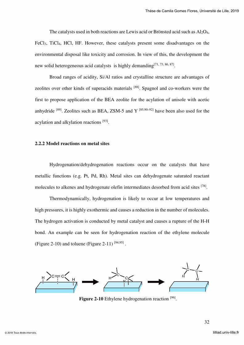
Thermodynamically, hydrogenation is likely to occur at low temperatures and
high pressures, it is highly exothermic and causes a reduction in the number of molecules.
The hydrogen activation is conducted by metal catalyst and causes a rupture of the H-H
bond. An example can be seen for hydrogenation reaction of the ethylene molecule
(Figure 2-10) and toluene (Figure 2-11) [94,95] .
Figure 2-10 Ethylene hydrogenation reaction [96].

33
The interest to toluene hydrogenation has been increasing because of more strict
requirements to the quality of diesel fuels as cetane number and the environmental
legislative rules. Toluene has similar properties but lower toxicity than benzene, for these
reasons it has been used in many applications replacing benzene. The Figure 2-11 shows
toluene hydrogenation forming methyl-cyclohexane product and the catalytic cracking
forming cyclohexane and methane as by-products [97–100].
Figure 2-11 Toluene hydrogenation and product cracking [98].
2.2.3 Fischer-Tropsch Synthesis
Fischer Tropsch Synthesis (FTS) is a reaction that produces hydrocarbons from
syngas (CO and H2). The syngas is obtained from coal, natural gas, and biomass and is
aimed for producing chemicals and fuels (Figure 2-12). FTS produces cleaner fuels and
allows non-use or minimization of the use of petroleum resources [101–103]. The interest to
FTS strongly depends on the crude oil prices, which vary cyclically over last decades.
These days they are approaching 53 $ per barrel according to EIA, 2019.

34
Figure 2-12 Conversion of non-petroleum sources to syngas for producing chemicals
and liquids fuel (adapted from [104]).
Fischer Tropsch synthesis includes parallel and consecutive reactions, determined
according to the operational conditions. Amongst them, the main are:
Paraffin synthesis: �2� + 1� ∙ �� + ��� → ������� + ����
Olefin synthesis: 2� ∙ �� + ��� → ����� + ����
Alcohol synthesis: 2� ∙ �� + ��� → ��������� + �� − 1� ∙ ���
Water Gas Shift (WGS): �� + ��� → �� + ���
Boudouard reaction (coke): 2�� → � + ���
Oxidation of metal: �� + ��� → �� + ���
In these reactions, � is the carbon number in hydrocarbons and alcohols. Several
parameters can affect the performance of Fischer Tropsch synthesis, such as
temperatures, composition of the gas (H2/CO ratio) and type of catalysts.
There are two types of FT processes: High Temperature Fischer-Tropsch (HTFT)
and Low Temperature Fischer-Tropsch (LTFT). The first process (HTFT) operates at
high temperatures at the range from 320 to 350 ºC and uses iron as catalyst. It generates

35
olefins, oxygenates and paraffins of gasoline range. In the LTFT process, the reactions
are carried out at lower temperatures (220 to 250 ºC) using iron or cobalt catalysts. The
process produces mainly long-chain linear paraffins. Indeed, the LTFT synthesis will
produce preferably middle distillates, which are used for formulation of diesel fuels [61].
The FT reaction mechanism consists of surface polymerization that yields a
product distribution with different molecular weights, known as Anderson-Schulz-Flory
(ASF) distribution [105]. The mechanism involves the following steps shown (Figure
2-13):
(1) Reagent adsorption;
(2) Chain initiation;
(3) Chain growth;
(4) Chain termination;
(5) Products desorption;
(6) Readsorption and secondary reactions.
Figure 2-13 FTS mechanism [106].
The distribution of hydrocarbon products is described by the ASF distribution via
Equation 1.
36
� = !
" !� #$ (1)
where %& is the initiation chain, %' is the termination chain and � is the chain-growth
probability. The chain growth towards olefins and paraffins is usually between 0.77 and
0.93 [107]. The termination probability will be (1-α). The relation between growth chain
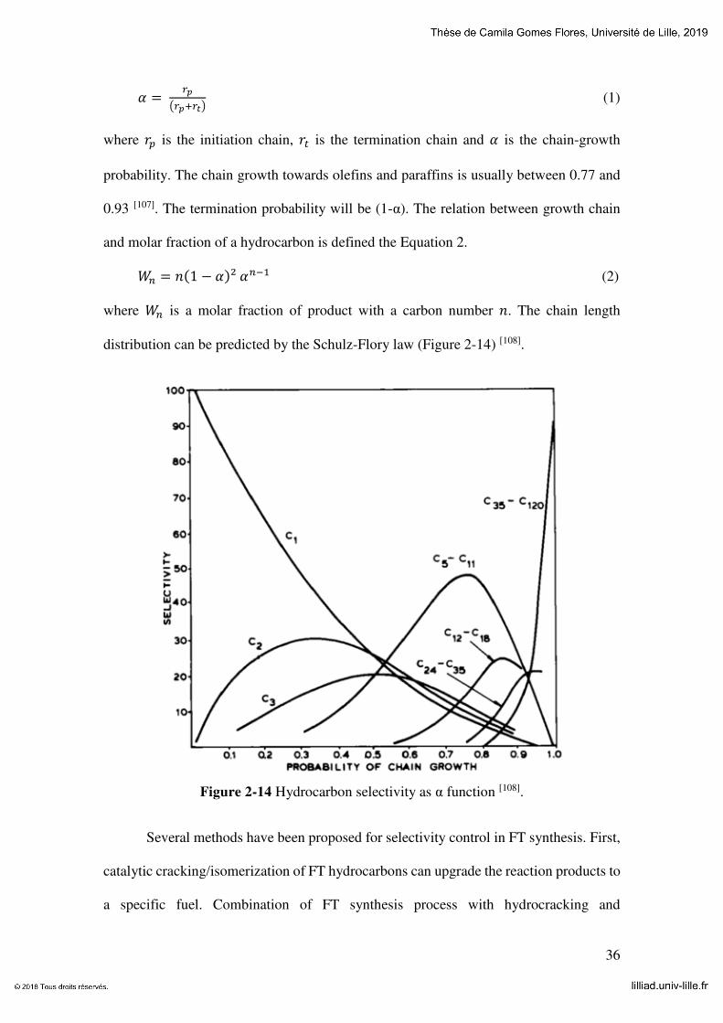
and molar fraction of a hydrocarbon is defined the Equation 2.
(� = ��1 − ��² ��*� (2)
where (� is a molar fraction of product with a carbon number �. The chain length
distribution can be predicted by the Schulz-Flory law (Figure 2-14) [108].
Figure 2-14 Hydrocarbon selectivity as α function [108].
Several methods have been proposed for selectivity control in FT synthesis. First,
catalytic cracking/isomerization of FT hydrocarbons can upgrade the reaction products to
a specific fuel. Combination of FT synthesis process with hydrocracking and

37
isomerization of long chain hydrocarbons restricts the hydrocarbon distribution to a more
convenient range [109]. The isomerization and cracking of FT hydrocarbons would lead to
iso-paraffins or diesel fuels constituted by the C10-C20 hydrocarbons. This multistage
process, however, significantly reduces the efficiency of synthetic fuel production.
An alternative to that multi-stage process would be utilization of bifunctional
catalysts containing an active FT component, e.g. cobalt (Co) or ruthenium (Ru), and an
acid catalyst active for cracking and isomerization. The proximity between metal and acid
sites is an important parameter of the bifunctional catalysts often governing reaction rate
and selectivities. Recently two additional methods for hydrocarbon selectivity control
were proposed, which involve making use of nanoreactors [110] and microemulsions [111].
In these methods, the carbon chain length is limited by steric and diffusion limitations
[112].
Fischer Tropsch mechanism is still under debates. Some mechanisms were
proposed to literature which involve carbide, hydroxylcarbene and carbonyl insertion.
1) Surface carbide is formed firstly by CO and H2 dissociation on metal particles
supported, forming C1 intermediates (without oxygen atoms). After that, the carbide
reacts with adsorbed hydrogen, generating intermediates such as CH, CH2 and/or CH3,
due to hydrogenation of carbon atoms. The chain growth is promoted by the insertion of
CHx species to CxHy, it is adsorbed into the metal particle. The chain termination is
followed by: (i) dehydrogenation to olefins, (ii) hydrogenation of CxHy intermediates to
paraffins or (iii) disproportional growth of CxHy intermediates to paraffins or olefins.
Methylene (CH2 adsorbed) is often considered the key intermediate specie (Figure 2-15).

38
Figure 2-15 Carbene mechanism [113].
2) Hydroxycarbene mechanism entailing partial hydrogenation of adsorbed CO to
adsorbed hydroxycarbene (CHOH) species. Thereafter, it involves a condensation
reaction of two –CHOH species, with the elimination of water at the same time, forming
– RCHOH intermediates (Figure 2-15).
This mechanism explains the formation of paraffinic and olefinic hydrocarbons by OH
bond elimination.
3) Carbonyl insertion mechanism is essentially different of two mechanisms previously
mentioned, because the CO molecule keeps unaltered. The growth of hydrocarbon chain
occurs through CO insertion into the metal-alkyl bonds (Figure 2-16).
Figure 2-16 Schematic representation of carbonyl insertion [113].
Carbonyl insertion mechanism is based on the results obtained with
organometallic complexes and was proposed for the first time by Pichler and Schulz
(1970). When catalysts on the basis of ruthenium or iron are used, this mechanism is
often supposed to occur [114].

39
2.2.4 Catalysts
The right choice of catalysts for the Fischer Tropsch synthesis is one the most
important factors in order to obtain high reaction yield. The catalysts must be active,
selective and stable. If it is possible, they can be regenerated. Several metals can be used
as catalysts in this reaction, the main are: cobalt (Co), iron (Fe), ruthenium (Ru) and nickel
(Ni) [115].
The iron catalysts normally are used because of their low cost. Besides that, these
catalysts present a good performance using syngas rich in CO or CO2, because of their
high activity in the water gas shift reaction. The main disadvantages of iron catalysts is
lower activity and rapid deactivation by oxidation or sintering [116].
Ruthenium is the most active catalyst for Fischer Tropsch synthesis, but its high
cost and limited reserves make it impossible industrial application. [117,118].
Cobalt-based catalysts present high activity, stability, C5+ hydrocarbons
selectivity and low activity in the WGS reaction. Cobalt catalysts are used in the low
temperature process (LTFT- Low Temperature Fischer Tropsch synthesis) for synthesis
of diesel fuels, whereas at high temperatures they produce a lot of methane (CH4). Besides
that, these catalysts have high activity in hydrogenation and tend to form preferably linear
alkanes, undesirable in the gasoline production, one of the main products of HTFT
process [119, 120]. In the state of the art catalysts, cobalt nanoparticles are dispersed on
porous supports like Al2O3, TiO2, SiO2, zeolites and others [9,121,122]. Higher activity,
higher conversion per single pass, higher resistance to deactivation by water, lower
activity in WGS and lower amount of oxygenate products are main advantages that cobalt
presents in front of iron-based catalysts.

40
References
1. Shlögl, R. Combinatorial Chemistry in Heterogeneous Vatalysis: A New Scientific Approch or ̈ the King’s New Clothes"? Angewandte Chemie International Edition (1998).
2. Plana-pallejà, J., Abelló, S., Berrueco, C. & Montané, D. Applied Catalysis A : General Effect of zeolite acidity and mesoporosity on the activity of Fischer – Tropsch Fe / ZSM-5 bifunctional catalysts. 515, 126–135 (2016).
3. Lee, W. et al. Effects of hierarchical zeolites on aromatization of acetylene. Catal.
Today 303, 177–184 (2018).
4. Jia, X., Khan, W., Wu, Z., Choi, J. & Yip, A. C. K. Modern synthesis strategies for hierarchical zeolites: Bottom-up versus top-down strategies. Adv. Powder Technol. (2018). doi:10.1016/j.apt.2018.12.014
5. Feliczak-Guzik, A. Hierarchical zeolites: Synthesis and catalytic properties. Microporous Mesoporous Mater. 259, 33–45 (2018).
6. Emdadi, L. et al. Synthesis of hierarchical lamellar MFI zeolites with sequential intergrowth influenced by synthetic gel composition. Microporous Mesoporous Mater. 275, 31–41 (2019).
7. Weitkamp, J. Zeolites and Catalysis. Solide State Ionics 131, 175–188 (2000).
8. Deldari, H. Suitable catalysts for hydroisomerization of long-chain normal paraffins. Appl. Catal. A Gen. 293, 1–10 (2005).
9. Steen, E. Van et al. TPR Study on the Preparation of Impregnated Co / SiO 2 Catalysts. 229, 220–229 (1996).
10. Schwarz, J. A., Contescu, C. & Contescu, A. Methods for Preparation of Catalytic Materials. Chem. Rev. 95, 477–510 (1995).
11. Almas, Q., Sievers, C. & Jones, C. W. Role of themesopore generation method in structure, activity and stability of MFI catalysts in glycerol acetylation. Appl. Catal. A
Gen. 571, 107–117 (2019).

41
12. Huang, Z. et al. Promoting effects of desilication and dealumination on the catalytic performance of Al-rich HMOR for catalysing naphthalene tert-butylation with tertiary butanol. Appl. Catal. A Gen. 572, 80–89 (2019).
13. Moliner, M. Direct Synthesis of Functional Zeolitic Materials. ISRN Mater. Sci. 2012, 1–24 (2012).
14. Koohsaryan, E. & Anbia, M. Nanosized and hierarchical zeolites : A short review. 37, 447–467 (2016).
15. Fang, Y., Hu, H. & Chen, G. Zeolite with tunable intracrystal mesoporosity synthesized with carbon aerogel as a secondary template. 113, 481–489 (2008).
16. Kustova, M., Egeblad, K., Christensen, C. H., Kustov, A. L. & Christensen, C. H. in Studies in Surface Science and Catalysis 170, 267–275 (2007).
17. Zhang, K. & Ostraat, M. L. Innovations in hierarchical zeolite synthesis. Catal. Today 264, 3–15 (2016).
18. Serrano, D. P., Escola, J. M. & Pizarro, P. Synthesis strategies in the search for hierarchical zeolites. Chem. Soc. Rev. 42, 4004–4035 (2013).
19. Kharchenko, A. Properties of copper species stabilized in zeolite nanocrystals. (Normandie Université, 2017).
20. Silva Filho, S. H. da et al. Synthesis of Zeolite A employing Amazon kaolin waste. Cerâmica 61, 409–413 (2015).
21. Sklenak, S. et al. N2O decomposition over Fe-zeolites: Structure of the active sites and the origin of the distinct reactivity of Fe-ferrierite, Fe-ZSM-5, and Fe-beta. A combined periodic DFT and multispectral study. J. Catal. 272, 262–274 (2010).
22. Odedairo, T., Balasamy, R. J. & Al-Khattaf, S. Influence of mesoporous materials containing ZSM-5 on alkylation and cracking reactions. J. Mol. Catal. A Chem. 345, 21–36 (2011).
23. Mihailova, B. et al. Interlayer stacking disorder in zeolite beta family: A Raman spectroscopic study. Phys. Chem. Chem. Phys. 7, 2756–2763 (2005).

42
24. Díaz-Cabañas, M. J. et al. Synthesis and structure of polymorph B of Beta zeolite. Stud. Surf. Sci. Catal. 174, 233–236 (2008).
25. Na, R. et al. Comptes Rendus Chimie Transformation of South African coal fl y ash into ZSM-5 zeolite and its application as an MTO catalyst. Comptes rendus - Chim. 20, 78–86 (2017).
26. Wang, Y., Ma, J., Ren, F., Du, J. & Li, R. Hierarchical architectures of ZSM-5 nanocrystalline aggregates with particular catalysis for lager molecule reaction. Microporous Mesoporous Mater. 240, 22–30 (2017).
27. Lounis, Z. & Belarbi, H. The Nanostructure Zeolites MFI-Type ZSM5. Nanocrystals
and Nanostructures 43–62 (2018). doi:10.5772/intechopen.77020
28. Pérez-Ramírez, J., Christensen, C. H., Egeblad, K., Christensen, C. H. & Groen, J. C. Hierarchical zeolites: enhanced utilisation of microporous crystals in catalysis by advances in materials design. Chem. Soc. Rev. 37, 2530 (2008).
29. Bassan, Í. A. L. Catalisadores bifuncionais à base de silicoaluminofosfato e fosfatos de nióbio para emprego em reações de hidroisomerização e hidrocraqueamento do n-hexadecano. (2015).
30. Schwieger, W. et al. Hierarchy concepts: Classification and preparation strategies for zeolite containing materials with hierarchical porosity. Chem. Soc. Rev. 45, 3353–3376 (2016).
31. Deng, Z., Zhang, Y., Zhu, K., Qian, G. & Zhou, X. Carbon nanotubes as transient inhibitors in steam-assisted crystal- lization of hierarchical ZSM-5 zeolites. 159, 466–469 (2015).
32. Groen, J. C., Moulijn, J. A. & Pérez-Ramírez, J. Decoupling mesoporosity formation and acidity modification in ZSM-5 zeolites by sequential desilication-dealumination. Microporous Mesoporous Mater. 87, 153–161 (2005).
33. Groen, J. C., Jansen, J. C., Moulijn, J. A. & Pérez-Ramírez, J. Optimal aluminum-assisted mesoporosity development in MFI zeolites by desilication. J. Phys. Chem. B 108, 13062–13065 (2004).
34. Milina, M., Mitchell, S., Crivelli, P., Cooke, D. & Pérez-Ramírez, J. Mesopore quality

43
determines the lifetime of hierarchically structured zeolite catalysts. Nat. Commun. 5, 1–10 (2014).
35. Groen, J. C. et al. Creation of hollow zeolite architectures by controlled desilication of A1-zoned ZSM-5 crystals. J. Am. Chem. Soc. 127, 10792–10793 (2005).
36. Dai, G., Hao, W., Xiao, H., Ma, J. & Li, R. Hierarchical mordenite zeolite nano-rods bundles favourable to bulky molecules. Chem. Phys. Lett. 686, 111–115 (2017).
37. M. Opanasenko. Zeolite constructor kit: Design for catalytic applications. Catal.
Today 304, 2–11 (2018).
38. Chunfei Zhang, Hao Chen, Xiangwen Zhang, Q. W. TPABr-grafted MWCNT as bifunctional template to synthesize hieraschical ZSM-5 zeolite. Mater. Lett. 197, 111–114 (2017).
39. Huang, G. et al. Fast synthesis of hierarchical Beta zeolites with uniform nanocrystals from layered silicate precursor. Microporous Mesoporous Mater. 248, 30–39 (2017).
40. Saito, A. & Foley, H. C. Micelle-templated silicates as a test bed for methods of mesopore size evaluation. Microporous Mater. 3, 531–542 (1995).
41. Karlsson, A., Stöcker, M. & Schmidt, R. Composites of micro- and mesoporous materials: simultaneous syntheses of MFI/MCM-41 like phases by a mixed template approach. Microporous Mesoporous Mater. 27, 181–192 (1999).
42. Zhu, K., Sun, J., Zhang, H., Liu, J. & Wang, Y. Carbon as a hard template for nano material catalysts. J. Nat. Gas Chem. 21, 215–232 (2012).
43. Liu, J. et al. Hierarchical Macro-meso-microporous ZSM-5 Zeolite Hollow Fibers With Highly Efficient Catalytic Cracking Capability. Sci. Rep. 4, 1–6 (2014).
44. Shcherban, N. D., Ilyin, V. G. & Nauky, P. Preparation , physicochemical properties and functional characteristics of micromesoporous zeolite materials. Theor. Exp. Chem. 51, 331–349 (2016).
45. Verboekend, D., Chabaneix, A. M., Thomas, K., Gilson, J.-P. & Pérez-Ramírez, J. Mesoporous ZSM-22 zeolite obtained by desilication: peculiarities associated with

44
crystal morphology and aluminium distribution. CrystEngComm 13, 3408 (2011).
46. Chen, L.-H. et al. Hierarchically structured zeolites: synthesis, mass transport properties and applications. J. Mater. Chem. 22, 17381 (2012).
47. Chuang XIng, Guohui Yang, Peng Lu; Wenzhong Shen, Xikun Gai, Li Tan, Jianwei, Tiejun Wang, Ruiqin Yang, N. T. A hierarchically spherical Co-based zeolite catalyst with aggregated nanorods structure for improved FischereTropsch synthesis reaction activity and isoparaffin selectivity. Microporous Mesoporous Mater. 233, 62–69 (2016).
48. Luna, F. J. & Schuchardt, U. Modificação de zeólitas para uso em catálise. Quim.
Nova 24, 885–892 (2001).
49. Stöcker, M. Gas phase catalysis by zeolites. Microporous Mesoporous Mater. 82, 257–292 (2005).
50. Corma, A. Inorganic Solid Acids and Their Use in Acid-Catalyzed Hydrocarbon Reactions. Chem. Rev. 95, 559–614 (1995).
51. Juzsakova, T. et al. Study on the Alkylaton Mechanism of Isobutane With 1-Butene Using Environmental Friendly Catalysts. Environ. Eng. Manag. J. 13, 2343–2347 (2014).
52. Li, S. et al. Extra-framework aluminium species in hydrated faujasite zeolite as investigated by two-dimensional solid-state NMR spectroscopy and theoretical calculations. Phys. Chem. Chem. Phys. 12, 3895 (2010).
53. Gackowski, M., Kuterasiński, Ł., Podobiński, J., Sulikowski, B. & Datka, J. IR and NMR studies of hierarchical material obtained by the treatment of zeolite Y by ammonia solution. Spectrochim. Acta - Part A Mol. Biomol. Spectrosc. 193, 440–446 (2018).
54. Zhang, W. & Smirniotis, P. G. Effect of zeolite structure and acidity on the product selectivity and reaction mechanism for n-octane hydroisomerization and hydrocracking. J. Catal. 182, 400–416 (1999).
55. Farneth, W. E. & Gorte, R. J. Methods for Characterizing Zeolite Acidity. Chem. Rev. 95, 615–635 (1995).
56. Dias, S. C. L. & Dias, J. A. Effects of the dealumination methodology on the FER

45
zeolite acidity: A study with fractional factorial design. Mol. Catal. 458, 139–144 (2018).
57. Weisz, P. B. Polyfunctional Heterogeneous Catalysis. Adv. Catal. 13, 137–190 (1962).
58. Song, Y. Q. et al. Effect of variations in pore structure and acidity of alkali treated ZSM-5 on the isomerization performance. J. Mol. Catal. A Chem. 310, 130–137 (2009).
59. Z.B. Wang, A. Kamo, T. Yoneda, T. Komatsu, T. Y. Isomerization of n-heptane over Pt-loaded zeolite/3 catalysts. Appl. Catal. A Gen. 159, 119–132 (1997).
60. Bao, J., Yang, G., Okada, C., Yoneyama, Y. & Tsubaki, N. H-type zeolite coated iron-based multiple-functional catalyst for direct synthesis of middle isoparaffins from syngas. Appl. Catal. A Gen. 394, 195–200 (2011).
61. Sartipi, S. Bifunctional catalysts for the direct production of liquid fuels from syngas. (Delft University of Technology The, 2014).
62. Miyaji, A. et al. Selectivity and mechanism for skeletal isomerization of alkanes over typical solid acids and their Pt-promoted catalysts. Catal. Today 74, 291–297 (2002).
63. Chica, A., Corma, A. & Miguel, P. J. Isomerization of C 5 – C 7 n -alkanes on unidirectional large pore zeolites : activity , selectivity and adsorption features. 65, 101–110 (2001).
64. Kinger, G., Majda, D. & Vinek, H. N-heptane hydroisomerization over Pt-containing mixtures of zeolites with inert materials. Appl. Catal. A Gen. 225, 301–312 (2002).
65. Cejka, J., Bekkum, H. van, Avelino, C. & Ferdi, S. Introduction to Zeolite Science
and Practice. (Elsevier Science, 2007).
66. Deraz, N. M. The comparative jurisprudence of catalysts preparation methods: I. Deposition-precipitation and adsorption methods. J. Ind. Environ. Chem. 2, 1–3 (2018).
67. Rasouli, M., Atashi, H., Mohebbi-kalhori, D. & Yaghobi, N. Bifunctional Pt/Fe-ZSM-5 catalyst for xylene isomerization. J. Taiwan Inst. Chem. Eng. 78, 438–446 (2017).
68. Hou, X., Qiu, Y., Yuan, E., Zhang, X. & Liu, G. SO4 2−/TiO2 promotion on HZSM-

46
5 for catalytic cracking of paraffin. "Applied Catal. A, Gen. 537, 12–23 (2017).
69. Chao, L. I., Hui, W., Shan-shan, Z. H. U., Guang-bo, L. I. U. & Jin-hu, W. U. Research on butene oligomerization reaction over the hemicellulose modified HZSM-5. J. Fuel
Chem. Technol. 45, 1088–1094 (2017).
70. Rui, J. et al. Synthesized high-silica hierarchical porous ZSM-5 and optimization of its reaction conditions in benzene alkylation with methanol. Chinese Chem. Lett. 30, 757–761 (2019).
71. Aleixo, R. et al. Kinetic study of Friedel-Crafts acylation reactions over hierarchical MCM-22 zeolites. Mol. Catal. 434, 175–183 (2017).
72. S.G. Wagholikar, P.S. Niphadkar, S. Mayadevi, S. S. Acylation of ansiole with long-chain carboxylic acids over wide pore zeolites. Appl. Catal. A Gen. 317, 250–257 (2007).
73. Chen, Z., Feng, Y., Tong, T. & Zeng, A. Effects of acid-modified HBEA zeolites on thiophene acylation and the origin of deactivation of zeolites. Appl. Catal. A Gen. 482, 92–98 (2014).
74. Olah, G. A.; Prakash, G. K. S.; Molnar, Á.; Sommar, J. Superacid Chemistry. John
Wiley & Sons, Inc. (2009). doi:10.1002/9780470421604
75. Steijns, M. & Froment, G. F. Hydroisomerization and Hydrocracking. 3. Kinetic Analysis of Rate Data for n-Decane and n-Dodecane. Ind. Eng. Chem. Prod. Res. Dev. 20, 660–668 (1981).
76. Sartipi, S., Van Dijk, J. E., Gascon, J. & Kapteijn, F. Toward bifunctional catalysts for the direct conversion of syngas to gasoline range hydrocarbons: H-ZSM-5 coated Co versus H-ZSM-5 supported Co. Appl. Catal. A Gen. 456, 11–22 (2013).
77. Bessell, S. Investigation of bifunctional zeolite supported cobalt Fischer-Tropsch catalysts. Appl. Catal. A, Gen. 126, 235–244 (1995).
78. Weitkamp, J. Catalytic Hydrocracking-Mechanisms and Versatility of the Process. ChemCatChem 4, 292–306 (2012).
79. Corma, A., Planelles, J. & Tomás, F. The influence of branching isomerization on the

47
product distribution obtained during cracking of n-heptane on acidic zeolites. J. Catal. 94, 445–454 (1985).
80. Jentoft, F. C. & Gates, B. C. Solid-acid-catalyzed alkane cracking mechanisms: Evidence from reactions of small probe molecules. Top. Catal. 4, 1–13 (1997).
81. Kotrel, S., Knözinger, H. & Gates, B. C. The Haag-Dessau mechanism of protolytic cracking of alkanes. Microporous Mesoporous Mater. 35–36, 11–20 (2000).
82. Narayanan, S. & Deshpande, K. Aniline alkylation over solid acid catalysts. Applied
Catalysis A: General 199, (2000).
83. Kocal, J. A., Vora, B. V. & Imai, T. Production of linear alkylbenzenes. Appl. Catal.
A Gen. 221, 295–301 (2001).
84. Gore, P. H. The Friedel-Crafts Acylation Reaction and its Application to Polycyclic Aromatic Hydrocarbons. Chem. Rev. 55, 229–281 (1955).
85. Kim, J. C., Cho, K., Lee, S. & Ryoo, R. Mesopore wall-catalyzed Friedel-Crafts acylation of bulky aromatic compounds in MFI zeolite nanosponge. Catal. Today 243, 103–108 (2015).
86. Bernardon, C., Ben Osman, M., Laugel, G., Louis, B. & Pale, P. Acidity versus metal-induced Lewis acidity in zeolites for Friedel–Crafts acylation. Comptes Rendus Chim. 20, 20–29 (2017).
87. Kubů, M. et al. Three-dimensional 10-ring zeolites: The activities in toluene alkylation and disproportionation. Catal. Today 259, 97–106 (2016).
88. Corma, A., José Climent, M., García, H. & Primo, J. Design of synthetic zeolites as catalysts in organic reactions. Appl. Catal. 49, 109–123 (1989).
89. Bonati, M. L. M., Joyner, R. W. & Stockenhuber, M. On the mechanism of aromatic acylation over zeolites. Microporous Mesoporous Mater. 104, 217–224 (2007).
90. Srivastava, R. Synthesis and applications of ordered and disordered mesoporous zeolites: Present and future prospective. Catal. Today 309, 172–188 (2018).

48
91. Procházková, D., Kurfiřtová, L. & Pavlatová, J. Acylation of p-xylene over zeolites. Catal. Today 179, 78–84 (2012).
92. Kantam, M. L., Ranganath, K. V. S., Sateesh, M., Kumar, K. B. S. & Choudary, B. M. Friedel-Crafts acylation of aromatics and heteroaromatics by beta zeolite. J. Mol.
Catal. A Chem. 225, 15–20 (2005).
93. Bernardon, C. Catalyseurs « Verts » Pour La Synthese Organique : (Université de Strasbourg, 2016).
94. Yadav, R. & Sakthivel, A. Silicoaluminophosphate molecular sieves as potential catalysts for hydroisomerization of alkanes and alkenes. Appl. Catal. A Gen. 481, 143–160 (2014).
95. Arribas, M. A., Concepción, P. & Martínez, A. The role of metal sites during the coupled hydrogenation and ring opening of tetralin on bifunctional Pt(Ir)/USY catalysts. Appl. Catal. A Gen. 267, 111–119 (2004).
96. Batalha, N. M. R. Optimization of the balance between activity and selectivity on a hydroisomerization catalyst. (Université de Poitiers, 2012).
97. Szegedi, Á., Popova, M., Mavrodinova, V. & Minchev, C. Cobalt-containing mesoporous silicas-Preparation, characterization and catalytic activity in toluene hydrogenation. Appl. Catal. A Gen. 338, 44–51 (2008).
98. Loiha, S. et al. Catalytic enhancement of platinum supported on zeolite beta for toluene hydrogenation by addition of palladium. J. Ind. Eng. Chem. 15, 819–823 (2009).
99. Hashemi, M., Teymouri, M., Rashidi, A. & Khodaei, M. M. Mesoporous catalyst of Co/MWCNTs as an effective catalyst in toluene hydrogenation and data analysis using response surface methodology (RSM). Mater. Lett. 126, 253–258 (2014).
100 .Suppino, R. S., Landers, R. & Cobo, A. J. G. Influence of noble metals (Pd, Pt) on the performance of Ru/Al2O3based catalysts for toluene hydrogenation in liquid phase. Appl. Catal. A Gen. 525, 41–49 (2016).
101. Xiong, H., Motchelaho, M. A. M., Moyo, M., Jewell, L. L. & Coville, N. J. Correlating the preparation and performance of cobalt catalysts supported on carbon nanotubes and carbon spheres in the Fischer – Tropsch synthesis. J. Catal. 278, 26–40

49
(2011).
102. Wen, X. et al. Performance of hierarchical ZSM-5 supported cobalt catalyst in the Fischer-Tropsch synthesis. J. Fuel Chem. Technol. 45, 950–955 (2017).
103. Yuelun Wang, Yuan Jiang, Juan Huang, Jing Liang, Hui Wang, Zhuo Li, Jinhu Wu, Min Li, Yunpeng Zhao, J. N. Effect of hierarchical crystal structures on the properties of cobalt catalysts for Fischer–Tropsch synthesis. Fuel 174, 17–24 (2016).
104. Carvalho, A. A. B. Investigation of intrinsic activity of cobalt and iron based Fischer-Tropsch catalysts using transient kinetic methods. ( Université de Lille, 2017).
105. van Wechem, V. M. H. & Senden, M. M. G. Conversion of natural gas to transportation fuels via the shell middle distillate synthesis process(smds). Stud. Surf. Sci.
Catal. 81, 43–71 (1994).
106. Gholami, Z., Asmawati Mohd ZabiDi, N., Gholami, F., Ayodele, O. B. & Vakili, M. The influence of catalyst factors for sustainable production of hydrocarbons via Fischer-Tropsch synthesis. Rev. Chem. Eng. 33, 337–358 (2017).
107. Khodakov, A. Y., Chu, W. & Fongarland, P. Advances in the development of novel cobalt Fischer-Tropsch catalysts for synthesis of long-chain hydrocarbons and clean fuels. Chem. Rev. 107, 1692–1744 (2007).
108. King, F., Shutt, E. & Thornson, A. I. Ruthenium Catalyst Systems for the Production of Hydrocarbons from Coal recent studies on the fischer-tropsch reaction Process Developments. 146–154 (1985).
109. Bouchy, C., Hastoy, G., Guillon, E. & Martens, J. A. Fischer-Tropsch waxes upgrading via hydrocracking and selective hydroisomerization. Oil Gas Sci. Technol. 64, 91–112 (2009).
110. Subramanian, V., Cheng, K., Lancelot, C. & Heyte, S. Nanoreactors: An E ffi cient Tool To Control the Chain-Length Distribution in Fischer − Tropsch Synthesis †. (2016). doi:10.1021/acscatal.5b01596
111. Ordomsky, V. V., Khodakov, A. Y., Legras, B. & Lancelot, C. Fischer–Tropsch synthesis on a ruthenium catalyst in two-phase systems: an excellent opportunity for the control of reaction rate and selectivity. Catal. Sci. Technol. 4, 2896–2899 (2014).

50
112. Li, Z., Wu, L., Han, D. & Wu, J. Characterizations and product distribution of Co-based Fischer-Tropsch catalysts: A comparison of the incorporation manner. Fuel 220, 257–263 (2018).
113. Todic, B., Ma, W., Jacobs, G., Davis, B. H. & Bukur, D. B. CO-insertion mechanism based kinetic model of the Fischer – Tropsch synthesis reaction over Re-promoted Co catalyst. Catal. Today 228, 32–39 (2014).
114. Yang, J. et al. Reaction mechanism of CO activation and methane formation on Co Fischer-Tropsch catalyst: A combined DFT, transient, and steady-state kinetic modeling. J. Catal. 308, 37–49 (2013).
115. Bessell, S. Support effects in cobalt-based fischer-tropsch catalysis. Appl. Catal. A,
Gen. 96, 253–268 (1993).
116. Plana-pallejà, J., Abelló, S., Berrueco, C. & Montané, D. Effect of zeolite acidity and mesoporosity on the activity of Fischer – Tropsch Fe/ZSM-5 bifunctional catalysts. Appl. Catal. A Gen. 515, 126–135 (2016).
117. Phaahlamohlaka, T. N., Kumi, D. O., Dlamini, M. W., Jewell, L. L. & Coville, N. J. Ruthenium nanoparticles encapsulated inside porous hollow carbon spheres: A novel catalyst for Fischer–Tropsch synthesis. Catal. Today 275, 76–83 (2016).
118. Kang, J. et al. Mesoporous zeolite-supported ruthenium nanoparticles as highly selective fischer-tropsch catalysts for the production of C5-C11 isoparaffins. Angew.
Chemie - Int. Ed. 50, 5200–5203 (2011).
119. Yang, J., Ma, W., Chen, D., Holmen, A. & Davis, B. H. Fischer-Tropsch synthesis: A review of the effect of CO conversion on methane selectivity. Appl. Catal. A Gen. 470, 250–260 (2014).
120. Zhang, Y., Xiong, H., Liew, K. & Li, J. Effect of magnesia on alumina-supported cobalt Fischer-Tropsch synthesis catalysts. J. Mol. Catal. A Chem. 237, 172–181 (2005).
121. Martínez, A., López, C., Márquez, F. & Díaz, I. Fischer-Tropsch synthesis of hydrocarbons over mesoporous Co/SBA-15 catalysts: The influence of metal loading, cobalt precursor, and promoters. J. Catal. 220, 486–499 (2003).
122. Liu, Y., Dintzer, T., Ersen, O. & Pham-Huu, C. Carbon nanotubes decorated ??-

51
Al2O3 containing cobalt nanoparticles for Fischer-Tropsch reaction. J. Energy Chem. 22, 279–289 (2013).

52
Chapter 3: Influence of impregnation and ion exchange sequence on metal
localization, acidity and catalytic performance of cobalt zeolite catalysts in Fischer-
Tropsch synthesis
Paper published in ChemCatChem, October 2018, IF 4.67, Qualis A1.
Abstract: Cobalt distribution between the external surface and micropores and acidity of
the large pore BEA zeolite were controlled by choosing the sequence of impregnation and
ion exchange procedures. Higher concentration of ion exchangeable cobalt was observed
in the catalyst prepared by ion-exchange of the zeolite proton form. The presence of Na+
instead of H+ ions in the exchange positions of zeolite favored deposition of cobalt on the
external surface. The acid sites in the zeolite micropores can be then restored by
subsequent ion exchange of sodium with ammonium nitrate and calcination. The catalytic
performance of the cobalt zeolite catalysts prepared using different impregnation and ion
exchange procedures was tested in the Fischer-Tropsch synthesis. Higher reaction rates
were observed over the catalysts, which did not contain cobalt ions in the cation sites of
the zeolite. Lower methane selectivity, higher selectivity to long chain hydrocarbons and
high fraction of isomerized products are observed when cobalt species are located on the
zeolite outer surface and acid sites inside the BEA zeolite micropores.
3.1 Introduction
The depletion of fossil resources and increasing environmental concerns have led
to the development of new catalytic processes from alternative and renewable feedstocks.
Natural gas and biomass can be transformed into syngas (CO+H2) by steam reforming,
partial oxidation or gasification. The syngas can be then converted into ultra-clean fuels

53
over cobalt-based catalysts via Fischer-Tropsch (FT) synthesis [1-3] FT synthesis is a
“nontrivial surface polymerization reaction” [4], with the reaction selectivity typically
described by very broad Anderson-Schulz-Flory distribution [1, 5]. Consequently, the
major challenge of FT reaction is adjustment of the reaction selectivity in order to produce
specific hydrocarbon fractions.
Several methods were proposed for selectivity control in FT synthesis. Some of
them involve control of hydrocarbon selectivity by steric limitation and diffusion in
nanoreactors and microemlusions [6-8]. The combination of FT synthesis with
hydrocracking and isomerization of long-carbon chain hydrocarbons restricts the
hydrocarbon distribution to a more convenient narrow range [9, 10]. Isomerization and
cracking of FT hydrocarbons would lead to iso-paraffins or diesel fuels mostly constituted
by the C10-C20 hydrocarbons. This reaction can be performed over hybrid or composite
catalysts containing an active FT component, e.g. Co or Ru, and an acid catalyst active in
cracking and isomerization.
Because of their high acidity and stability, zeolites have been often proposed as
most promising catalysts for hydrocarbon cracking and isomerization under FT synthesis
conditions [3, 11]. Impregnation is an effective method for the preparation of bi-functional
cobalt-zeolite catalysts for the direct production of fuels from syngas [12-18]. Note
however, that introduction of cobalt ions to the zeolite may result however, in the
neutralization of the zeolite acid sites. This represents a major drawback of this method.
Cobalt ions, introduced during impregnation, can occupy cation exchange positions in the
zeolite micropores decreasing the number of acid sites available for hydrocarbon
isomerization and cracking. In addition, the isolated Co ions in the cationic positions can
be very difficult to reduce to metallic state, thus decreasing the amount of available metal
active phase for FT synthesis. Finally, it is known that the diffusion in zeolites is strongly

54
affected by the presence of exchange cations inside the micropores [19-21]. The metal
particles in the narrow zeolite micropores are more susceptible to suffer from diffusion
limitations due to the small pores of the zeolite in the presence of larger compensation
cations. The diffusion limitations in the zeolite micropores in particular for carbon
monoxide would lead to higher methane selectivity [22]. In addition, use of larger
compensation cations during impregnation can restrain diffusion of Co ions inside the
zeolite pores during the ion exchange and thus affect cobalt distribution between the
zeolite external surface and micropores of the zeolite. The diffusion of reagents,
intermediates and reaction products is usually much faster in the H-from of the zeolites
and more particularly in the BEA zeolite, which has larger pore diameters compared to
mordenite and most commonly used ZSM-5 zeolite. It can be also expected that HBEA
zeolite which has weaker Brönsted acidity [13] than H-ZSM-5 might reduce overcracking
and exhibit higher selectivity to isomerized hydrocarbons.
This chapter focuses on the effect of the impregnation sequence while introducing
cobalt ions on the metal localization in zeolite and catalytic performance in FT synthesis.
Cobalt was introduced by impregnation either to the sodium or proton forms of BEA
zeolite. The as-prepared cobalt zeolite catalysts were calcined after the impregnation and
then submitted to NH4+ ion exchange. The Brönsted acidity was restored in the zeolite by
decomposition of NH4+ ions at higher temperature. All samples, before and after
regeneration of the acid sites, were characterized by a wide range of methods and tested
in FT synthesis.
55
3.2 Experimental Section
Catalyst synthesis
A commercial NH4BEA zeolite (Zeolyst, CP-814E, Si/Al=12.5) was used for
preparation of all catalysts. The H+ form of the BEA zeolite (HBEA) was obtained via
calcination of the parent NH4BEA sample at 450 °C for 4 h. The Na+ form (NaBEA) was
prepared by two successive ion exchanges of HBEA with a 2 M NaCl (Janssen Chimica,
P.A) solution at 80 °C for 1 h (50 mL·gsample-1), followed by calcination at 450 °C for
4 h. Cobalt and platinum were introduced to the HBEA and NaBEA zeolites through
incipient wetness impregnation by using Co(NO3)2 (2.39 mol L-1 solution) (Sigma-
Aldrich, 98%) and Pt(NH3)4(NO3)2 (Sigma-Aldrich) as precursors. The amounts of
precursors were calculated to obtain 20 wt.% of cobalt and 0.1 wt.% platinum in the final
samples. After the impregnation, the samples were calcined at 450 °C for 4 h. The
impregnated HBEA and NaBEA are denoted as Co/HBEA and Co/NaBEA, respectively.
The calcined Co/HBEA and Co/NaBEA catalysts were submitted to two
successive ion exchanges with 2 M NH4NO3 (Sigma-Aldrich, 98%) solution at 80 °C for
1 h (50 mL•gsample-1), followed by calcination at 450 °C for 4 h. The final samples after
the ion exchange with NH4+ and calcination are denoted as CoH/HBEA and CoH/NaBEA.
Catalyst characterization
The calcined samples were characterized by X-ray diffraction (XRD) by using a
D8 Advance diffractometer equipped with an energy dispersive type detector and a
monochromatic CuKα radiation source. The XRD patterns were measured using a step of
0.02° with an acquisition time of 0.5 s. The average size of cobalt oxide (Co3O4)
nanoparticles was determined by the Scherrer equation.

56
The samples chemical composition was determined by ICP-OES analysis. The
zeolite samples for the analysis were dissolved a mixture of aqua regia and hydrofluoric
acid. Quantitative elemental analyses were performed by inductively coupled plasma-
optic emission spectroscopy 720-ES ICP-OES (Agilent) with axially viewing and
simultaneous CCD detection. The quantitative determination of metal content in the
catalysts was made based on the analysis of certificated standard solution. The ICP
ExpertTM software (version 2.0.4) provides the weight percentage of components.
The textural properties of the samples were determined by N2 physisorption using
a Micromeritics ASAP 2000 apparatus. Prior to the analysis, the samples were degassed
under vacuum (10 µmHg) at 350 °C for 4 h. The total pore volume (TPV) was calculated
from the amount of vapor adsorbed at a relative pressure P/P0 = 0.97. The catalyst
microporous volume (Vmicro) were calculated using the deBoer t-plot method. The
samples mesoporous volume was calculated as the difference between the total pore
volume and microporous volume.
The XPS spectra were taken using a Kratos Axis spectrometer, equipped with an
aluminum monochromater for a 1486.6 eV source working at 120 W. All spectra were
recorded under a vacuum of 10-8 Torr and recalibrated afterwards with the binding
energy of the Al 2p at 74.6 eV.
The catalyst Brönsted and Lewis acidities were measured using Infrared
spectroscopy after pyridine adsorption on a Nicolet 8700 apparatus. The samples were
pretreated under vacuum (10-3 torr) at 450 °C for 2 h. After the pre-treatment, pyridine
(1.2 mbar) was adsorbed on the sample at room temperature. The samples were then
heated under vacuum (10-3 torr) at 150 °C and a spectrum was taken at room temperature.
The intensity of the Py-L and Py-H+ peaks at ~ 1455 and 1545 cm-1 was measured as a
function of temperature, and the resulting plots used to compare the zeolite acidity.

57
Fischer-Tropsch synthesis
The catalytic performance of the samples was tested in FT synthesis. The
experiments were performed in a fixed-bed reactor. Prior to testing, the samples were
reduced in-situ in pure H2 gas flow at 400 °C for 4 h with a temperature ramping rate of
3 °C/min. After the reactor was cooled down to room temperature, the flow was switched
to syngas (H2/CO = 2) and the pressure was adjusted to 20 bar. Nitrogen (5% of the CO
flow) was used as internal standard. The flow was adjusted to obtain GHSV of
66 L/gCo.h-1). After achieving the desired pressure, the temperature was progressively
increased to the reaction temperature, i.e. 250 °C, at the ramping rate of 3 °C/min. The
gaseous reaction products, i.e. up to C5, were analyzed online using gas chromatography.
The liquid products were condensed under pressure and analyzed off-line using a
Shimatzu 2010-Plus-AF gas chromatograph.
3.3 Results and Discussion
Catalyst characterization
The catalyst characterization data are shown in Table 3-1. The H-form of BEA
zeolite impregnated with cobalt (Co/HBEA) contains 13.7 wt.% of cobalt and only trace
amounts of sodium. The amount of cobalt added by impregnation to the sodium form of
the zeolite was almost the same (14.3 wt.%). Note that the Co/NaBEA samples contained
in addition to cobalt about 1 wt.% of sodium. Subsequent ion exchange of the Co/HBEA
and Co/NaBEA samples with ammonia nitrate results in decrease in cobalt content in the
catalysts. The decrease in cobalt content after the ion exchange with NH4NO3 is more
significant in the Co/HBEA catalyst. This suggests that Co/HBEA contains a higher
fraction of cobalt ion in the zeolite cation positions. Only very slight decrease in cobalt
content was observed in Co/NaBEA. Most of cobalt seems to be present in this catalyst

58
as cobalt oxide clusters rather than isolated cobalt ions in the cation sites. The ion
exchange with ammonia nitrate leads to a major decrease in the concentration of sodium
in the Co/NaBEA zeolite.
The Co3O4 oxide phase was identified in the catalysts using IR, Raman
spectroscopies and XRD. The IR spectra of the cobalt zeolite catalysts are shown in
Figure S1 (SI, Supporting Information). They exhibit the peaks at 670 and 555-600 cm−1,
which were assigned to the ν (Co–O) vibration modes in Co3O4 [23]. Note that these bands
overlap with the bands at 622, 525 and 468 cm-1 related respectively to coupled Al-O and
Si-O out-of-plane vibrations, Al-O-Si and Si-O-Si bending vibrations in zeolite [24, 25].
The broad bands at 1350-1000 cm-1 are due to asymmetric Si–O(Si,Al) and Al–OH
bending vibrations. Figure S2, SI shows the Raman spectra of the catalysts. They are also
indicative of the presence of the Co3O4 phases. The intense band at 667 cm-1 is attributed
to the cobalt octahedral sites (CoO6) [23, 26, 27]. The medium intensity bands at 465 and
505 cm−1 correspond to the Eg and F2g(2) sites, respectively, while the weak band located
at 606 cm−1 has the F2g(1) symmetry.
The cobalt oxide crystallite sizes in the calcined samples were estimated from
broadening of the Co3O4 characteristic XRD peak at 36.8° (2θ, Figure S3, SI). All the
samples showed similar cobalt oxide crystallite size, i.e. between 23-26 nm, once gain
indicating that the secondary ion exchanges performed with CoH/HBEA and
CoH/NaBEA had no effect on the size of larger cobalt oxide particles which are most
probably localized on the external surface of zeolite. Note that XRD might not be
sensitive to the presence of much smaller cobalt oxide nanoparticles in the zeolite
micropores (<1 nm). Indeed, sub-nanometric clusters of cobalt oxides located inside the
micropores of BEA zeolites prepared by impregnation were detected by STEM analysis
in our recent publication [22].

59
The porous volume and surface areas of zeolites significantly decreased after the
impregnation with cobalt compared to the parent samples. The reduction of the
mesoporous and microporous volume observed after cobalt impregnation indicates that
cobalt oxide nanoparticles are localized in both types of the pores. The microporous
volume decreases by 12% and 18%, respectively, on Co/HBEA and Co/NaBEA. This
phenomenon can be explained by the presence of Co3O4 inside the zeolite crystallites [28].
Higher loss of microporous volume observed on Co/NaBEA can be directly linked to the
presence of Na+ localized in the zeolite micropores. Slower diffusion of cobalt ions in the
micropores of Na/BEA results in preferential localization of cobalt ions in the entrances
of the zeolite pores. This could lead to easier blocking of the pores of NaBEA zeolite with
cobalt species.
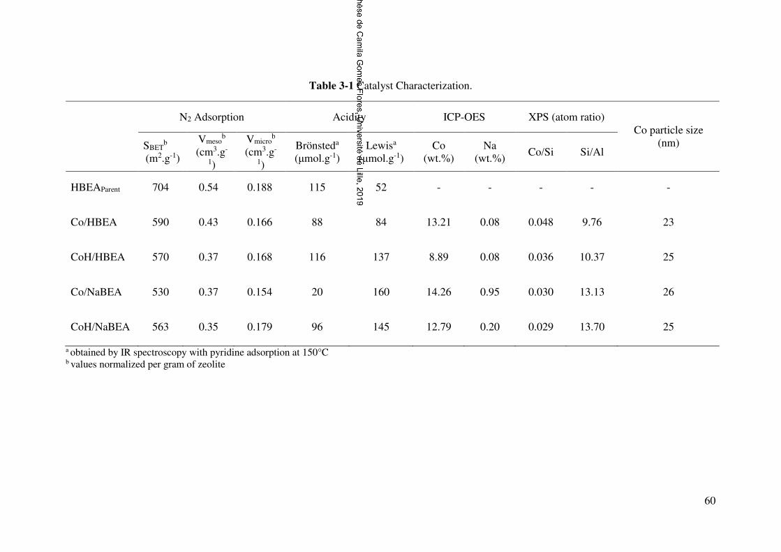
60
Table 3-1 Catalyst Characterization.
N2 Adsorption Acidity ICP-OES XPS (atom ratio) Co particle size
(nm) SBETb
(m2.g-1)
Vmesob
(cm3.g-
1)
Vmicrob
(cm3.g-
1)
Brönsteda (μmol.g-1)
Lewisa (μmol.g-1)
Co (wt.%)
Na (wt.%)
Co/Si Si/Al
HBEAParent 704 0.54 0.188 115 52 - - - - -
Co/HBEA 590 0.43 0.166 88 84 13.21 0.08 0.048 9.76 23
CoH/HBEA 570 0.37 0.168 116 137 8.89 0.08 0.036 10.37 25
Co/NaBEA 530 0.37 0.154 20 160 14.26 0.95 0.030 13.13 26
CoH/NaBEA 563 0.35 0.179 96 145 12.79 0.20 0.029 13.70 25
a obtained by IR spectroscopy with pyridine adsorption at 150°C b values normalized per gram of zeolite

61
After regeneration of the catalyst acidity via ion exchange with NH4+ ions and
calcination, CoH/NaBEA recovered most of the original microporosity, i.e. only 5%
Vmicro loss. Similarly, after NH4+ ion exchange, Co/HBEA recovered a much smaller
portion of micropore volume. The recovery of the zeolite micropore volume after ion
exchange with NH4+ is linked to the removal of Na+ and Co2+ exchanged species from the
zeolite framework. Consequently, more significant recovery of micropore volume was
observed on CoH/NaBEA. This indicates a lower concentration of sub-nanometric cobalt
oxide clusters inside of the zeolite micropores of NaBEA compared to the BEA zeolite
H-form.
Introduction of cobalt ions to the zeolite also leads to the decrease in the
mesoporous volume formed by intracrystalline spaces between zeolite crystals.
Interestingly, different to microporous volume, the subsequent ion exchange does not
result in the reversible recovery of this volume. This indicates that, for all samples, the
decrease in mesoporous volume is principally due to the formation of cobalt oxide
nanoparticles, which are non-soluble in aqueous solutions. These cobalt oxide
nanoparticles, which form during catalyst calcination are located either in the mesopores
or on the external surface of zeolite. This decreases interaction between the zeolite
crystallites and thus mesoporous volume [15, 21, 22].
The Co 2p XPS spectra (Figure 3-1) show that Co3O4 is the dominant cobalt phase
in oxidized catalysts. For CoH/HBEA and CoH/NaBEA, the shapes and binding energies
of the Co2p line (
Figure 3-1) at 780 eV and low-intense shake-up satellite structure with spin-
orbital splitting of 15.2 eV were very similar to those of bulk Co3O4 [29]. Higher intensities
of the satellite peaks, a shift of the XPS lines towards the higher energy region and an

62
increase in spin-orbital splitting observed for the XPS spectra of Co/HBEA and
Co/NABEA indicate the presence of Co2+ ions [30, 31].
Figure 3-1 Co 2p XPS spectra of the calcined cobalt BEA zeolite catalysts.
Indeed, the Co/HBEA and Co/NaBEA samples prepared by impregnation of
HBEA and NaBEA zeolite contain Co2+ ions in the zeolite cationic sites in addition to the
Co3O4 crystallites. These cations are then removed by ion exchange with ammonium
nitrate. The XPS Co/Si ratio (Table 3-1) almost does not change after the secondary ion
exchange, while the cobalt content may decrease more significantly in particular for the
Co/HBEA catalyst. This suggests that only a very small amount of cobalt is removed by
ion exchange from the zeolite outer surface. Indeed, cobalt is present in the subsurface
layers of the zeolite crystals mostly as Co3O4, which is refractory to the ion exchange.
775780785790795800805810815
Binding Energy, eV
Co/HBEA
CoH/HBEA
Co/NaBEA
CoH/NaBEA
Co2p3/2
Co2p1/2

63
The catalyst acidity was also impacted by the catalyst preparation method (Table
3-1). Due to the presence of cobalt oxide and cobalt ions in the exchange positions of the
zeolite, the amount of Lewis acid sites was higher in the impregnated catalysts compared
to the pristine zeolite [32]. The zeolite Brönsted acidity also depends on the presence of
the compensation ions inside the zeolite micropores. As expected, in Co/NaBEA, the
concentration of Brӧnsted acid sites was much lower than on other samples, due to the
neutralization of the protonic sites by sodium. After NH4+ exchange and calcination, the
concentration of Brönsted acid sites significantly increases due to the removal of cobalt
ions from the cation exchange positions in Co/HBEA and to the removal of both cobalt
and sodium ions from CoH/NaBEA. Still, the Brӧnsted acidity in CoH/NaBEA remains
slightly lower than in CoH/HBEA. Note that the NH4+ ion exchange also results in the
increase in the micropore volume because of the removal of bulky cations from the
micropores (Table 3-1).
Figure 3-2 TPR catalyst reduction profiles.
The TPR profiles (Figure 3-2) clearly show that the reducibility of cobalt
nanoparticles is strongly affected by the presence of sodium ions in the zeolites during
impregnation. Typically, the reduction of cobalt oxide (Co3O4) to metallic cobalt under
hydrogen atmosphere occurs in two consecutive steps: Co3O4 → CoO → Co [33].

64
The two- step reduction is translated into two distinct peaks in the TPR profile.
According to the stoichiometry, the area of the first peak should be 3 times smaller than
that of the second. Figure 3-2 suggests that the reduction of Co3O4 to CoO is easier when
the cobalt was impregnated over the proton form zeolite as the first reduction peak in
Co/BEA and Co/HBEA is observed at 190 °C instead of 290-310 °C. This effect might
be explained by hydrogen spillover in the presence of acid sites close to metal oxide. In
comparison, when the cobalt impregnation is performed over the sodium form of BEA
zeolite, the cobalt reduction only starts at 310 °C. The first reduction peak slightly shifts
to 290 °C after the zeolite exchange to acid form which might be explained partial
hydrogen transfer through zeolite acidity. Interestingly, this phenomenon is not observed
for the second reduction peak (CoO to Co) with the hydrogen consumption peak
appearing at the same temperature for all catalysts, i.e. around 420-430 °C. Previous
reports [34, 35] suggest negative effect of alkali ions on cobalt reducibility. Note that no
such effect was observed over Co/NaBEA zeolite (Figure 3-2) which is probably due to
separate localization of cobalt and sodium species. Cobalt is preferentially localized on
the zeolite outer surface, while sodium ions are located in the cation positions inside the
zeolite crystallites.
Localization of cobalt species in CoH/HBEA and CoH/NaBEA zeolites after
removal of cobalt ions form the zeolite cation sites is illustrated in Figure 3-3.To
summarize, the CoH/HBEA and Co/HBEA catalysts prepared by impregnation contain
cobalt as cobalt ions and cobalt oxide nanoparticles both in the pore and on the outer
surface of the zeolite, while the Co/NaBEA and CoH/NaBEA mostly cobalt oxide
particles located on the surface of the zeolite crystallites.

65
Figure 3-3 Localization of cobalt species in the CoH/HBEA (a) and CoH/NaBEA
zeolite (b).
Catalytic performance in FT synthesis
All the catalysts showed significant reaction rate in FT synthesis. No changes in
the catalyst activity were observed during 100 h of the reaction. Nonetheless, the catalyst
activity and selectivity were significantly affected by the catalyst preparation method
(Table 3-2).
After the NH4+ ion exchange and calcination, the activity of the CoH/HBEA
catalysts increased by 132% compared to Co/HBEA and by 23% when comparing
CoH/NaBEA to Co/NaBEA. Higher activity observed on the catalysts after ion exchange
could be explained by the removal of cobalt and sodium ions from the zeolite micropores,
higher concentration of zeolite Brӧnsted acid sites and easier diffusion of reaction
intermediates to the acid sites inside the zeolite crystallites. The effect of NH4+ ion
exchange and calcination on the catalytic performance is more pronounced for Co/HBEA
where higher amounts of cobalt ions and cobalt active phase are located inside of the
micropores. Ion exchange results in the removal of cobalt ions from the cation sites and
reappearance of Brönsted acid sires. This result also indicates that the FT reaction rates
are enhanced when cobalt nanoparticles and Brӧnsted acid sites are located in the
proximity [13].

66
Once again, the catalytic data confirm distinct localization of cobalt and sodium
species in Co/NaBEA samples. Alkali metal ions were reported [34, 35] to be poisons for
conventional supported cobalt FT catalysts. Preferential localization of cobalt on the outer
surface of NaBEA zeolite and sodium ions inside the zeolite pores leads to very weak
interaction between cobalt and sodium in Co/NaBEA, very small cobalt poisoning and
thus, a high catalytic activity of this sample. Similar phenomenon was observed early for
Y-zeolites [36]. In the Y-zeolite, sodium had very small influence of the intrinsic activity
of cobalt species because of sodium preferential localization in small cages on Y-zeolite,
while cobalt was mainly present in the mesopores.
The product selectivities over different cobalt-zeolite catalysts are shown in Table
3-2 and Figure 3-4. Significant differences were observed as functions of catalyst
preparation procedures. The selectivity towards methane was higher, when cobalt was
impregnated on HBEA when compared to NaBEA, i.e. 22.2% compared to 17.5%. HBEA
zeolite contained cobalt nanoclusters localized in the zeolite pores where their sizes are
limited by the the pore diameters. Previously it was shown [37] that cobalt particle size
smaller than 6 nm might lead to higher methane selectivity. In addition, localization of
cobalt nanoparticles into the zeolite micropores in Co/HBEA introduces diffusion
limitations for carbon monoxide, which results in higher H2/CO ratio in the micropores
and thus, leads to higher methane selectivity [38]. Higher methane selectivity was recently
observed [22] over Co/zeolite catalysts containing cobalt nanoparticles only inside the
zeolite crystals. The catalysts were prepared by selective extraction of cobalt from the
zeolite outer surface using heteropolyacids. The Co/NaBEA contains mostly cobalt
species on the zeolite external surface and was therefore less selective to methane.
After the NH4+ ion exchange, methane selectivity increases to 29% on Co/HBEA,
whereas on CoH/NaBEA a slight decrease to 16.1% is observed. Similar trends were

67
observed for the C2-C4 hydrocarbon selectivity. Co/HBEA was less selective to the C5+
hydrocarbons followed by CoH/HBEA, Co/NaBEA and CoH/NaBEA, respectively with
48.7, 63.9, 66 and 71.9%. The C2-C4 olefins to paraffins ratio (Table 3-2) show slight
differences between the samples [39, 40].
Table 3-2 Catalytic performance in FT at iso-coversion.*
FT activity (molCO.gCo
-1.h) XCO2
% SCO2 SCH4 C2-C4
SC5+
Isomer fraction in C9+ wax,
% Alpha
STotal Olefin / Paraffin
Co/HBEA 0.65 72 0.6 22.2 13.3 0.30 63.9 67 0.63
CoH/HBEA 1.51 74 1.6 29.0 20.7 0.22 48.7 63 0.48
Co/NaBEA 0.79 63 1.5 17.5 15.0 0.35 66.0 47 0.76
CoH/NaBEA 0.97 68 0.5 16.1 11.4 0.31 71.9 65 0.60
*Conversion is around 70% obtained though different GHSV (GHSV = 66 Lg.Co-1.h-1)
The wax composition for each catalyst is presented in Figure 3-5. The presence of
n-paraffin and isomerized products was observed for all samples. No significant
differences in the total isomer fraction among the catalysts were observed, with the
exception of Co/NaBEA where a smaller amount of Brӧnsted acid sites (Table 3-1) led
to lower selectivity to branched hydrocarbons. The catalyst preparation method also
affects the hydrocarbon chain length in the wax products. On Co/NaBEA, hydrocarbons
up to 25 carbons were observed, whereas for CoH/HBEA the carbon chain growth was
limited to 20 carbons. The chain probability growth factor (α) determined by applying the
ASF distribution model (Table 3-2, Figure 3-5) showed that the samples capacity to
produce long carbon chain products decreases in the following order:
Co/NaBEA>Co/HBEA>CoH/NaBEA>CoH/HBEA. The distribution of liquid products
seems to be affected by both localization of metal phase and concentrations of Brӧnsted
acid sites.

68
Figure 3-4 Wax products (C9+) distribution.
Figure 3-5 ASF distribution plot for the wax products obtained from the FT synthesis
reaction.
Co/NaBEA has lower concentration of Brönsted acid sites, which are neutralized
by Na+, and the metal was mostly located on the external surface of the zeolite.
Consequently, the hydrocarbons formed on the metal sites on the zeolite outer surface
were less likely to undergo isomerization and cracking. Higher selectivity to long chain
hydrocarbons was observed.
On CoH/NaBEA, the metal location is similar to Co/NaBEA. Most of cobalt is
localized on the zeolite external surface. The zeolite Brönsted acidity was obtained after
exchange of Na+ with NH4+ ions and subsequent calcination. Consequently, the
9 10 11 12 13 14 15 16 17 18 19 20 21 22 23 24 25Carbon number
Co/NaBEA
n-paraffin
isomer products
9 10 11 12 13 14 15 16 17 18 19 20 21 22 23 24 25Carbon number
Co/HBEA
n-paraffin
isomer products
9 10 11 12 13 14 15 16 17 18 19 20 21 22 23 24 25Carbon number
CoH/NaBEA
n-paraffin
isomer products
9 10 11 12 13 14 15 16 17 18 19 20 21 22 23 24 25Carbon number
CoH/HBEA
n-paraffin
isomer products

69
CoH/NaBEA sample showed improved isomerization and cracking rates compared to
Co/NaBEA. On Co/HBEA, the metal species are located both on the external surface of
zeolite and inside the micropores. Some of Brönsted acid sites in Co/HBEA are
neutralized by cobalt cations. The smaller size of the metal sub-nanometric cobalt clusters
located in the confined space of the zeolite micropores and, the proximity to the acid sites
contribute to shorter carbon chain length of the formed products [6, 37, 41, 42]. On the one
hand, localization of cobalt metal particles inside the zeolite micropores could lead to the
diffusion limitations in particular for carbon monoxide and would increase locally the
H2/CO ratio. Higher H2/CO ratio would favor higher selectivity to methane and light
hydrocarbons. On the other hand, the short diffusion pathway of the paraffins produced
over cobalt clusters located inside the zeolite framework to the acid sites improves
isomerization and cracking reactions and leads to the formation of smaller carbon chain
products. It is important to mention that the higher methane selectivity observed on
Co/HBEA and CoH/HBEA is directly linked to the FT synthesis, since methane
formation through β-scission does not usually occur [43] and the protolytic cracking
mechanism is unlikely to occur under the reaction conditions [44].
The preferential deposition of cobalt on the BEA zeolite external surface was
proven to be an effective way to achieve simultaneously high FT reaction rate and lower
methane selectivity. Removal of cobalt ions from the zeolite micropores by ion exchange
results in the enhancement of the selectivity to the isomerized long chain hydrocarbons
over Co/NaBEA zeolite. This catalyst has both high C5+ selectivity and higher fraction of
isomerized hydrocarbons in the wax products. It is important to mention that Na+ ions are
not bulky enough to completely stop diffusion of Co2+ ions inside the micropores during
impregnation. Consequently, the use of bulkier ions, e.g. K+, or direct impregnation after
zeolite synthesis before template removal, might be possible options to reduce the cobalt

70
ions diffusion inside the framework. The BEA zeolite has relatively large pores. The
situation could be different for ZSM-5 with narrow zeolite pores (d= 5.5 Å) and in
particular in the samples with larger zeolite crystallites. The diffusion limitation in ZSM-
5 zeolites can become much more severe. The preferential localization of cobalt species
on the outer surface of ZSM-5 might not be optimal for the enhanced catalytic
performance.
3.4 Conclusion
The zeolite impregnation procedure and ion exchange sequence have a very strong
impact on the structure and localization of cobalt species in BEA zeolite and catalytic
performance in FT synthesis. Occupation of the zeolite cation exchange sites by sodium
ions favored deposition of cobalt during impregnation with cobalt nitrate on the zeolite
external surface. Cobalt deposition on the H-from of BEA zeolite via impregnation results
in cobalt localization both on the zeolite outer surface and in the zeolite micropores.
Simultaneous deposition of cobalt on the BEA zeolite external surface and in the
micropores leads to cracking and higher methane selectivities. The sample with the metal
particles on the external surface and high concentration of Brӧnsted acid sites in the
zeolite micropores, i.e. CoH/NaBEA exhibited lower methane, higher selectivity to long
chain hydrocarbons and significant yield of isomerized hydrocarbons.

71
References
[1] A.Y. Khodakov, W. Chu, P. Fongarland, Chem. Rev. 2007, 107, 1692–1744.
[2] B.H. Davis, M.L. Occelli, Stud. Surf. Sci. Catal. 2006, 163, 1–420.
[3] Q. Zhang, K. Cheng, J. Kang, W. Deng, Y. Wang, ChemSusChem 2014, 7, 1251–
1264.
[4] H. Schulz, Catal. Today 2014, 228, 113–122.
[5] G. Henrici‐Olivé, S. Olivé, Angew. Chemie Int. Ed 1976, 15, 136–141.
[6] V. Subramanian, K. Cheng, C. Lancelot, S. Heyte, S. Paul, S. Moldovan, O. Ersen,
M. Marinova, V. V. Ordomsky, and A. Y. Khodakov, ACS Catal. 2016, 6, 1785−1792.
[7] Y. Chen, N. Batalha, M. Marinova, M. Impéror-Clerc, C. Ma, O. Ersen, W. Baaziz,
J.A.Stewart, D. Curulla-Ferré, A. Y.Khodakov, Vitaly V.Ordomsky, J. Catal. 2018, 365,
429-439.
[8] V. V. Ordomsky, A. Y. Khodakov, B. Legras and C. Lancelot, Catal. Sci. Technol.
2014, 4, 2896-2899.
[9] Bouchy, C., Hastoy, G., Guillon, E., Martens, J. A., Oil Gas Sci. Technol. - Rev. IFP
2009, 64, 91–112.
[10] C. Flores, N. Batalha, V. V. Ordomsky, V. L. Zholobenko, W. Baaziz, N. R.
Marcilio, A. Y. Khodakov, ChemCatChem 2018, 10, 2291-2299.
[11] F. Pinto, R.N. André, C. Carolino, M. Miranda, Fuel Process. Technol. 2014, 126,
19–29.
[12] S. Bessell, Appl. Catal. A 1995, 126, 235–244.
[13] V. Subramanian, V.L. Zholobenko, K. Cheng, C. Lancelot, S. Heyte, J. Thuriot, S.
Paul, V. V. Ordomsky, A.Y. Khodakov, ChemCatChem 2016, 8, 380–389
[14] D.J. Koh, J.S. Chung, Y.G. Kim, Ind. Eng. Chem. Res. 1995, 34, 1969–1975.
[15] K. Jothimurugesan, S.K. Gangwal, Ind. Eng. Chem. Res. 1998, 37, 1181–1188.

72
[16] S. Bessell, Appl. Catal. A. 1993, 96, 253–268.
[17] K. Cheng, L. Zhang, J. Kang, X. Peng, Q. Zhang, Y. Wang, Chem. - A Eur. J. 2015,
21, 928–1937.
[18] S. Sartipi, M. Alberts, M.J. Meijerink, T.C. Keller, J. Pérez-Ramírez, J. Gascon, F.
Kapteijn, ChemSusChem 2013, 6, 1646–1650.
[19] H. Valdés, S. Alejandro, C.A. Zaror, J. Hazard. Mater. 2012, 227–228, 34–40.
[20] V.R. Choudhary, D.B. Akolekar, J. Mol. Catal. 1991, 66, 215–222.
[21] M.A. Keane, Microporous Mater. 1994, 3, 93–108.
[22] A. Carvalho, M. Marinova, N. Batalha, N.R. Marcilio, A.Y. Khodakov, V. V.
Ordomsky, Catal. Sci. Technol.2017, 7, 5019-5027.
[23] J. Jiang, L. Li, Materials Letters 2007, 61, 4894–4896.
[24] V.C. Farmer, The layer silicates. In: Farmer, V.C. (Ed.), The Infrared Spectra of
Minerals. Mineralogical Society, London, 1974, pp. 331 – 363.
[25] J. Madejov, M. Janek , P. Komadel, H.-J. Herbert , H.C. Moog, Applied Clay Science
2002, 20, 255 – 271.
[26] C.V. Ramana, M. Massot, C.M. Julien, Surf. Interface Anal. 2005, 37, 412-416.
[27] Z.V. Marinkovic Stanojevic, N. Romcevic, B. Stojanovic, J. Eur. Ceram. Soc. 2007,
27, 903-907.
[28] V. Subramanian, V.L. Zholobenko, K. Cheng, C. Lancelot, S. Heyte, J. Thuriot, S.
Paul, V. V Ordomsky, A.Y. Khodakov, ChemCatChem 2016, 8, 380–389.
[29] J.P. Bonnelle, J. Grimblot, A. D’huysser, A., J. Electron Spectr. 1975, 7, 151-162
[30] D.G. Castner, P.R. Watson and I.Y. Chan, J.Phys.Chem. 1989, 93, 3188-3194.
[31] S.W. Ho, M. Horialla, D.M. Hercules, J.Phys.Chem. 1990, 94, 6396-6399.
[32] G.A.. Mekhemer, H.M.. Abd-Allah, S.A.. Mansour, Colloids Surfaces A
Physicochem. Eng. Asp. 1999, 160, 251–259.

73
[33] E. Van Steen, G.S. Sewell, R.A. Makhothe, C. Micklethwaite, H. Manstein, M. De
Lange, C.T.O. Connor, J. Catal. 1996, 162, 220–229.
[34] A. H. Lillebø,E.Patanou, J. Yang,E.A.Blekkan, A.Holmen, Catal. Today 2013, 215,
60–66
[35] Ø.Borg, N.Hammer, B.C.Enger, R. Myrstad, O. A. Lindvag,S.Eri, T. H.Skagseth, E.
Rytter, J. Catal. 2011, 279,163 –173.
[36] X. Peng, K. Cheng, J. Kang, B. Gu, X. Yu, Q. Zhang, Y. Wang, Angew. Chem. – Int.
Ed. 2015, 54, 4553-4556.
[37] G. L. Bezemer, J. H. Bitter†, H. P. C. E. Kuipers, H. Oosterbeek, J. E. Holewijn, X.
Xu, F. Kapteijn, A. J. van Dillen, and K. P. de Jong, J. Am. Chem. Soc. 2016, 128, 3956-
3964.
[38] E. Iglesia, S.C. Reyes, R.J. Madon and S.L. Soled, Adv. Catal. 1993, 39, 221-.
[39] E. Janiszewska, M. Kot, M. Zieliński, Micro Mesopor Mater. 2018, 255, 94–102.
[40] J. Wang, Q. Li, J. Yao, Appl. Catal. A. 1999, 184, 181–188.
[41] Ø. Borg, P.D.C. Dietzel, A.I. Spjelkavik, E.Z. Tveten, J.C. Walmsley, S. Diplas, S.
Eri, A. Holmen, E. Rytter, J. Catal. 2008, 259, 161–164.
[42] J.P. den Breejen, P.B. Radstake, G.L. Bezemer, J.H. Bitter, V. Frøseth, A. Holmen,
K.P. de Jong, J. Am. Chem. Soc. 2009, 131, 7197–7203.
[43] J. Weitkamp, S. Ernst, Catal. Today 1994, 19, 107–149.
[44] A. Corma, P.J. Miguel, A. V Orchillés, J. Catal. 1997, 172, 355-369.

74
Supporting Information
Figure S1. IR spectra of cobalt zeolite catalysts.
Figure S2. Raman spectra of cobalt zeolite catalysts.
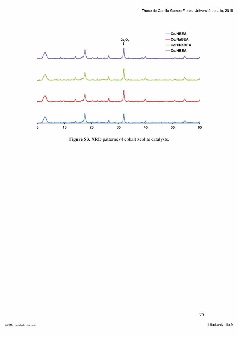
75
Figure S3. XRD patterns of cobalt zeolite catalysts.
5 15 25 35 45 55 65
Co/HBEA
Co/NaBEA
CoH/NaBEA
Co/HBEA
Co3O4

76
Chapter 4: Direct production of iso-paraffins from syngas over hierarchical cobalt-
ZSM-5 nanocomposites synthesized using carbon nanotubes as sacrificial templates
Paper published in ChemCatChem, February 2018, IF 4.67, Qualis A1
Abstract: This chapter focuses on the effect of synthesis conditions on the structure of
cobalt-ZSM-5 zeolites, localization, dispersion and reducibility of cobalt species and their
catalytic performance in Fischer-Tropsch synthesis. The zeolite catalysts were prepared
using carbon nanotubes as sacrificial templates. Addition of pristine carbon nanotubes
resulted only in a slight increase in the zeolite mesoporosity, while the presence of carbon
nanotubes impregnated with cobalt drastically modified the zeolite morphology and
texture. The zeolite mesoporous volume increased by 3-4 times. The catalysts prepared
using cobalt impregnated carbon nanotubes as templates showed 5-10 times higher
Fischer-Tropsch reaction rates normalized by reducible cobalt compared to the catalysts
prepared by conventional impregnation. Higher selectivity to isomerized branched
hydrocarbons on these zeolites was attributed to the enhanced diffusion favoring removal
of isomerized products and avoiding their cracking.
4.1 Introduction
The depletion of fossil resources and increasing environmental concerns have led
to the necessity for the development of new catalytic processes from alternative
renewable resources. Natural gas and biomass can be transformed into syngas (H2/CO)
and subsequently by Fischer-Tropsch (FT) synthesis over cobalt-based catalysts into
middle distillates and waxes [1-3]. FT synthesis is a “nontrivial surface polymerization
reaction [4], with reaction selectivity typically described by the broad Anderson-Schulz-

77
Flory distribution (ASF) [1, 5]. Consequently, the major challenge of FT reaction is to tune
the reaction selectivity to specific hydrocarbon fractions.
Several methods have been proposed for selectivity control in FT synthesis. First,
catalytic cracking/isomerization of FT hydrocarbons can upgrade the reaction products to
a specific fuel. Combination of FT synthesis with hydrocracking and isomerization of
long chain hydrocarbons restricts the hydrocarbon distribution to a more convenient range
[6]. The isomerization and cracking of FT hydrocarbons would lead to iso-paraffins or
diesel fuels constituted by the C10-C20 hydrocarbons. This multistage process, however,
significantly reduces the efficiency of synthetic fuel production.
An alternative to that multi-stage process would be to utilize bifunctional catalysts
containing an active FT component, e.g. Co or Ru, and an acid catalyst active for cracking
and isomerization. The proximity between metal and acid sites is an important parameter
of the bifunctional catalysts often governing reaction rate and selectivities. Recently two
additional methods for hydrocarbon selectivity control were proposed, which involve
making use of nanoreactors [7] and microemulsions [8]. In these methods the carbon chain
length is limited by steric and diffusion limitations.
Zeolites have been often suggested as promising catalysts for hydrocarbon
cracking and isomerization under the conditions similar to FT synthesis [3, 9]. An FT
catalyst can be combined with a zeolite through several different methods: in a dual bed
catalytic reactor with FT catalyst in the first layer followed by zeolite [10, 11]; in hybrid
catalysts prepared by mixing of FT catalyst and zeolite [12-14]; in the catalysts prepared by
zeolite impregnation with metal salts [13, 15-18]; and by composite zeolite/metal catalysts,
for example, core-shell materials [19, 20].
A significant number of research publications have been dedicated to direct
synthesis of gasoline and middle distillates over dual bed or hybrid catalysts obtained

78
through combination of supported Co catalysts and zeolites [10-16, 21-23]. Different types of
zeolite frameworks such as ZSM-5, MCM-22, IM-5, ITQ-2, BEA, MOR, and FAU with
and without addition of noble-metal promoters have been tested and combined with FT
synthesis catalysts. Still, slow diffusion of long-chain paraffins through zeolite pores, in
particular on medium-pore zeolites, leads to a preferential participation of the acid sites
on the zeolite external surface and lower isomerization efficiency [22].
Impregnation is another method for the preparation of bi-functional Co-zeolite
catalysts for direct production of fuels from syngas [13, 15-18, 24-26]. Still, this method
presents a major drawback that is the neutralization of the zeolite acid sites by cobalt ions.
Cobalt ions, introduced during impregnation, can occupy cation positions in the zeolite
framework decreasing the number of acid sites available for hydrocarbon isomerization
and cracking, while larger cobalt oxide particles can be detected on the outer surface of
zeolite. Additionally, isolated Co cations in the zeolite framework are very difficult to
reduce to metallic cobalt. Cobalt species on the zeolite outer surface have low dispersion
and generate insufficient number of active sites for FT reaction. This decreases the
amount of active phase for FT synthesis.
The improvement of zeolite diffusion properties through creating a hierarchical
porous network has been the subject of extensive research [27-30]. The application of this
type of materials was proven to be beneficial for the activity and selectivity of several
catalytic reactions including long-chain paraffin isomerization and cracking combined
with FT synthesis [26, 29-33]. Several synthesis methodologies, classified as top-down and
bottom-up have be applied to the synthesis of hierarchical zeolites. A mesoporous
network can be created directly by partially destroying the zeolite crystal through
desilication [27, 34] or dealumination [35, 36]. Alternatively, hierarchical zeolites can be
produced directly during the zeolite synthesis through the use of external templates that

79
are sacrificed after zeolite synthesis, e.g. carbon structures [28, 37] resins [38] or polymers
[39]. It is important to emphasize that cobalt is usually added to the zeolites in the second
step after hierarchization of the zeolite.
The goal of this work is to obtain in a one-pot synthesis composite hierarchical
zeolites with cobalt metal particles uniformly distributed in the zeolite mesoporous
structure. This has been achieved by using cobalt impregnated carbon nanotubes
(Co/CNT) as sacrificial templates during the synthesis of ZSM-5 zeolite. Two different
carbon nanotubes (CNT) with outer diameters of 10-20 nm and 20-40 nm were used to
induce mesoporosity in ZSM-5. The catalysts were characterized by low-temperature N2
adsorption, transmission electron microscopy (TEM), temperature-programmed
reduction (TPR) and FTIR spectroscopy with adsorbed pyridine (Py). The hierarchical
cobalt-zeolite samples were tested in FT synthesis and their catalytic performance in
particular relative to synthesis of iso-paraffins was compared with the Co/ZSM-5
catalysts prepared by conventional impregnation.
4.2 Experimental Section
Impregnation of carbon nanotubes with cobalt
Prior to the impregnation, the multiwalled carbon nanotubes (CNTs) were treated
with nitric acid to remove all metal contamination. Two different CNT samples (Iolitec
nanomaterial, 95%) with different diameters, that is, 10-20 nm and 20-40 nm, were used.
Typically, CNTs (3 g) were pretreated in concentrated HNO3 (68%, 210 mL) for 14 h
under reflux conditions. After, the samples were filtered, washed with distilled water until
pH 7, and dried at 100 °C overnight.
Cobalt and platinum were introduced to CNTs by wet impregnation method using
respectively Co(NO3)2*6H2O (Sigma-Aldrich, 98%) and Pt(NH3)4(NO3)2 (Sigma-

80
Aldrich) as precursors. Typically, Co(NO3)2 and Pt(NH3)4(NO3)2 solution (50 mL) was
used per gram of CNTs and the precursor amount was estimated to obtain a final
composition of 20 wt.% Co and 0.1 wt.% Pt. The mixture was submitted to ultrasonic
treatment for 30 min and dried at 80 °C. The samples were calcined at 400 °C for 4 h
under a nitrogen atmosphere.
After the calcination, the samples were treated with H2O2 to restore the
hydrophilic properties of the CNTs. Typically, 30 mL of 1:1 H2O2 (Sigma-Aldrich, 35%)
and distilled water were added to impregnated CNTs (2.56 g), which was sonicated for
30 min and dried at 80 °C.
Synthesis of hierarchical cobalt - ZSM-5
The ZSM-5 zeolite was synthesized by using the following initial composition of
the gel: 2.7NaCl:1Al2O3:12.5TPAOH:55.8SiO2:7500H2O. Sodium chloride (0.380 g,
Janssen Chimica, P.A.), tetrapropylammonium hydroxide (3.0 g, Sigma-Aldrich, 1M in
H2O), sodium aluminate (0.040 g, Sigma-Aldrich) and distilled water were mixed until a
clear solution was obtained. Then, Co/CNT (0.3 g) and tetraethyl orthosilicate (TEOS,
2.8 g, Sigma-Aldrich, 99%) were added to the solution. After, the synthesis gel was aged
for 1 h at room temperature under stirring. The synthesis gel was set inside a Teflon-lined
autoclave (40 mL) and the zeolite crystallization performed under static condition at
170 °C for 24 h. After cooling down, the solid was recovered by filtration and washed
until neutral pH. The final solid was calcined at 600 °C for 4 h under air.
Thermogravimetric analysis showed complete decomposition and oxidation of cobalt-
containing carbon nanotubes at temperatures below 400 °C. This suggests that cobalt
zeolite composite catalysts calcined at 600 °C in air did not contain any residual carbon
species.

81
For comparison, zeolite syntheses without addition of CNTs or in the presence of
CNTs, which did not contain cobalt ions, were performed. The prepared zeolites were
impregnated with cobalt and platinum precursors in the final catalysts.
To obtain the zeolite acid form, two successive exchanges using 2 M NH4NO3
aqueous solution at 80 °C for 1 h (1 g of zeolite per 50 mL of solution) were performed.
The ammonium form was converted into the protonic form by calcination at 450 °C for
4 h under air.
The synthesized samples were denoted as: CoCNT(x)/ZSM-5 for the samples
synthesized with cobalt and platinum co-impregnated CNTs (x represents the CNT
diameter used in the synthesis, that is, 10-20 or 20-40 nm); Co(x)/ ZSM-5 for the samples
synthesized with CNTs and subsequently impregnated with Co and Pt (x represents the
CNT diameter used in the synthesis, that is, 10-20 nm or 20-40 nm). Co/ZSM-5 stands
for the zeolite synthetized without addition of CNTs and impregnated with the Co and Pt
precursors.
Catalyst characterization
The samples were characterized by X-ray diffraction (XRD) by using a D8
Advance diffractometer equipped with an energy dispersive type detector and a
monochromatic CuKα radiation source. The samples were analyzed using a step of 0.02°
with an acquisition time of 0.5 s. The average size of cobalt oxide (Co3O4) crystallites
was determined by the Scherrer equation.
The sample chemical composition was determined by X-ray fluorescence (XRF)
on a spectrometer M4 TORNADO (Bruker). This instrument is equipped with 2 anodes:
rhodium X-ray tube 50 kV/600 mA (30 W) and a tungsten X-Ray tube 50 kV/700 mA
(35 W). For sample characterization, the rhodium X-rays with a poly-capillary lens

82
enabling excitation of an area of 200 μm were used. The detector used was a Silicon-
Drift-Detector Si(Li) with <145 eV resolution at 100000 cps (MnKα) and cooled with a
Peltier cooling (253°K). The measurement was done under vacuum (20 mbar).
Quantitative analysis was performed using fundamental parameter (FP; standardless).
The textural properties of the samples were determined by N2 physisorption on a
Micromeritics ASAP 2000 apparatus. Prior to analysis, the samples were degassed under
vacuum (10 µmHg) at 350 °C for 4 h. The total pore volume (TPV) was calculated from
the amount of vapor adsorbed at a relative pressure P/P0 = 0.97. The samples surface area
was estimated by the BET method, while the micropore volume and external surface were
calculated using the deBoer t-plot method.
The catalyst reducibility was studied using temperature-programmed reduction
(TPR) system with an Autochem II (Micrometrics) apparatus. The samples were reduced
under a flow of 5% H2 in argon (50 mL min-1) and heated up to 800 °C at a rate of
5 °C/min.
Comparative characterization of the acidic OH groups (Brönsted acid sites) and
Lewis acid sites in solid acids, e.g. zeolites, was carried out using transmittance FTIR
measurements in the 6000-900 cm-1 spectral range utilizing pyridine adsorption for
monitoring the strength and relative quantities of both Lewis and Brönsted acid sites.
FTIR transmittance measurements were performed at ~30 °C using self-supported disks
of studied materials activated at 450 °C for 5 h in vacuum (with the temperature ramp of
1 oC/min). FTIR spectra have been collected using a Thermo iS10 spectrometer at a 4 cm-
1 resolution (0.96 cm-1 data spacing). The spectra were analyzed and presented (including
integration, differentiation and determination of peak positions) using specialized Thermo
software, Omnic. Acidic properties of the samples were evaluated using temperature

83
programmed desorption of pyridine (Py) monitored spectroscopically. An excess of Py
was admitted into the transmittance cell at 150 °C, in a stepwise manner until no changes
were observed in the spectra. The saturated sample was then evacuated for 10 min at
150 °C to remove physically adsorbed Py and the FTIR spectrum collected. In the
transmittance TPD experiments, Py was removed under vacuum in a stepwise fashion at
150-450 °C, and the FTIR spectra were obtained at each temperature step, every 50 °C.
The intensity of the Py-L and Py-H+ peaks at ~ 1455 and 1545 cm-1 was measured as a
function of temperature, and the resulting plots used to compare the effective acidity of
the samples.
The TEM observations of the samples were obtained by using a Tecnai instrument
equipped with a LaB6 crystal operated at 200 kV. Before the analysis, the samples were
dispersed by ultrasound in ethanol for 5 min, and a drop of the suspension was deposited
onto a carbon membrane on a 300 mesh copper grid. The STEM-HAADF tomographic
analysis was carried out on a Jeol 2100F (field emission gun) microscope operating at
200 kV by using a spot size of 1.1 Å with a current density of 0.5 pA Å-1.
Catalytic tests
The catalytic performance of the samples was tested in FT synthesis. The
experiments were performed in a milli-fixed bed reactor. All the details of the catalytic
test relevant to mass and heat transfers are given in our earlier publication [53]. No
significant (>0.5 bar) pressure drop and temperature gradient are observed under the
reaction conditions. Prior to testing, the samples were reduced in situ in pure H2 gas flow
(3 mL min-1) at 400 °C for 4 h with a heating rate of 3 °C/min. Then, the reactor was
cooled down to room temperature, the flow switched to syngas (H2/CO = 2) and the

84
pressure adjusted to 20 bar. Nitrogen (5% of the CO flow) was used as internal standard.
The flow was adjusted to obtain a GHSV of 20-70 L/gCo.h. After achieving the desired
pressure, the temperature was progressively increased to the reaction temperature, i.e.
250 °C, at a rate of 3 °C/min. The reaction was conducted at 250 °C in order to create in
addition to FT synthesis favorable conditions for secondary reactions such as olefin
cracking and isomerization. The gas hourly space velocity (GHSV) was expressed in cm3
gcat-1 h-1. The units correspond to the volume of syngas, which passed through 1 g of
catalyst per hour. The gaseous reaction products, i.e. up to the C5 hydrocarbons were
analyzed online using gas-chromatography (GC×FID/TCD, Varian, CP-3800). The liquid
products were condensed under pressure and analyzed ex situ using a Shimadzu 2010-
Plus-AF gas-chromatograph.
4.3 Results and Discussion
Catalyst structure
The XRD patterns of the synthesized samples are displayed in Figure 4-1. All
samples present characteristic peaks of MFI zeolite. The presence of CNTs during
hydrothermal treatment does not affect to any noticeable degree the intensity of the XRD
peaks. The introduction of cobalt by impregnation or with CNTs during the zeolite
synthesis led to an overall reduction of the intensity of the zeolite characteristic peaks.
This was attributed to the effect of “dilution” and lower concentration of MFI phase in
these samples. The Co3O4 phase was detected using a characteristic peak at 2 θ equal to
36.8°in all samples containing cobalt. The particle size of Co3O4 calculated using the
Scherrer equation (Table 4-1) was in all cases between 27 and 44 nm, indicating that a
large fraction of cobalt is located either in the mesopores or on the zeolite external surface.
Interestingly, smaller diameter CNTs (10-20 nm) during zeolite crystallization led to the

85
formation of smaller Co3O4 particles, i.e. around 30 nm, when compared with the
synthesis without CNTs or using larger diameter CNTs (20-40 nm).
Figure 4-1 XRD patterns of cobalt ZSM-5 nanocomposites.
Table 4-1 Catalyst textural characterization.
Sample
N2 adsorption Co content
(wt %)
Co3O4 Particle size*
(nm)
SBET Vtot Vmic Vmeso
(m2g-1) (cm3g-1) (cm3g-1) (m2g-1)
ZSM-5 425 0.19 0.13 0.06 - - CNT(10-20)/ZSM-5 434 0.21 0.12 0.09 - - CNT(20-40)/ZSM-5 418 0.21 0.10 0.11 - -
Co/ZSM-5 372 0.17 0.11 0.06 15.6 44 Co(10-20)/ZSM-5 360 0.18 0.10 0.08 13.2 27 Co(20-40)/ZSM-5 276 0.13 0.08 0.05 12.7 40
CoCNT(10-20)/ZSM-5 435 0.32 0.09 0.23 7.8 29 CoCNT(20-40)/ZSM-5 395 0.25 0.09 0.16 9.4 42
The catalyst textural properties are listed in Table 4-1. The nitrogen adsorption
desorption isotherms are displayed in Figure S4 (Supporting information, SI). The
5 10 15 20 25 30 35 40
2 θ
ZSM-5
CNT(10-20)/ZSM-5
CNT(20-40)/ZSM-5
Co/ZSM-5
CoCNT(10-20)/ZSM-5
CoCNT(20-40)/ZSM-5
Co(10-20)/ZSM-5
Co(20-40)/ZSM-5
Co3O4ZSM-5 ZSM-5

86
introduction of CNTs without cobalt in the zeolite synthesis gel did not affect to any
greater extent the zeolite overall surface area. However, the catalyst porosity undergoes
significant changes. The mesoporous volume of the zeolites prepared using the 10-20 nm
and 20-40 nm diameter CNTs increased by 50% and 80%, respectively. This variation is
possibly caused by creating mesoporosity via removal of the CNTs incorporated inside
the zeolite crystals during crystallization [28].
After cobalt impregnation, a significant decrease in the sample surface area and
pore volume was observed. This decrease was attributed to the presence of Co3O4 which
can result in a partial plugging of the zeolite pores and “dilution” effect. In all cases, the
impregnation with cobalt nitrate also caused a decrease in the zeolite microporous
volume. This suggests that at least a part of cobalt is located inside the zeolite framework.
The mesoporous volume was however slightly higher in the samples synthetized in the
presence of CNTs (without cobalt). This seems to confirm partial incorporation of CNTs
into zeolites during their synthesis and subsequent generation of mesoporosity during the
CNT combustion.
The samples synthesized with Co/CNT as templates displayed surface area and
microporous volume similar to the pure zeolite (Table 4-1), while the mesoporous volume
was significantly increased. In comparison to the ZSM-5 samples synthesized with
pristine CNTs, the CoCNT(10-20)/ZSM-5 and CoCNT(20-40)/ZSM-5 mesoporous volume
was, respectively, 185% and 220% higher than that of Co(10-20)/ZSM-5
and Co(20- 40)/ZSM- 5.
The impact of the CNTs on the zeolite morphology was investigated by TEM
(Figure 4-2). The zeolite crystallization in the presence of CNTs led to the formation of
large pores in the zeolite crystals (Figure 4-2A). These pores were formed after
calcination when the CNTs were removed from the zeolite. The zeolite phase clearly

87
displayed imprinting coming from CNTs, which were partially encapsulated inside the
zeolite crystals during germination [26]. The presence of these regularly shaped pores was
not observed on zeolites crystallized in the presence of cobalt impregnated CNT (Figure
4-2B). In the presence of Co/CNT, the formed zeolite crystals took a less regular shape,
in agreement with the higher mesopore volumes observed for calcined CoCNT(10-
20)/ZSM-5 and CoCNT(20-40)/ZSM-5 (Table 4-1). Schematically the zeolite synthesis
process in the presence of Co/CNT is shown in Figure 4-3. Figure 4-2C and Figure 4-2D
show the formation of a uniform layered material. Importantly, these layered structures
are only observed when cobalt was present in CNT added to the zeolite synthesis mixture.
Indeed, the zeolite morphology replicates that of carbon nanotubes containing cobalt
nanoparticles.
Figure 4-2 TEM images of Co(10-20)/ZSM-5 (A), CoCNT(10-20)/ZSM-5(B), CoCNT(10-
20)/ZSM-5 high magnification(C) and CoCNT(20-40)/ZSM-5 high magnification.
In addition, Figure 4-2C and Figure 4-2D display a large number of small Co3O4
particles with a diameter between 1 and 5 nm as well as larger particles, i.e. 30-50 nm.
This suggests that the zeolite contains two types of cobalt particles: smaller cobalt
particles of 1-5 nm are located in the zeolite meso- and micropores, while larger cobalt
particles of 30-50 nm are situated in the zeolite mesopores and on the outer surface. Note

88
that only large Co3O4 crystallites can be detected in the zeolites by XRD, while it is
impossible to detect by XRD cobalt oxide particles smaller than 5 nm.
To confirm uniform distribution of cobalt nanoparticles in the zeolite mesopores,
we conducted additional experiments using the STEM-HAADF electron tomography.
The typical slices (xy) and (xz) extracted from the 3D volume calculated by tomography
of the sample CoCNT(20-40)/ZSM-5 prepared using Co/CNT(20-40) as sacrificial template
(Figure 4-4) show the presence of cobalt nanoparticles inside the mesoporous structure
of zeolite.
Thus, the electron microscopy results are clearly indicative of the important role
of cobalt located on CNTs for directing zeolite synthesis. Cobalt species probably act as
zeolite nucleation sites for designing mesoporous zeolites with the CNT-type morphology
(Figure 4-3).
Figure 4-3 Synthesis of ZSM-5 zeolite using Co/CNT as sacrificial templates. Resulting zeolites replicate carbon nanotube morphology.
The TPR profiles of the catalysts are shown in Figure 4-5. The reduction profiles
of the impregnated samples were consistent with the two-step Co3O4 reduction to metallic
Co. Co3O4 is first reduced to CoO which is then reduced to metallic Co, thus leading to
the formation of two H2 consumption peaks [13, 40]. In the samples prepared by
impregnation, i.e. Co/ZSM-5, Co(10-20)/ZSM-5 and Co(20-40)/ZSM-5, the characteristic
Co3O4 reduction peaks overlap leading to a broad peak with a “low temperature” shoulder
corresponding to the reduction of Co3O4 to CoO.

89
Figure 4-4 Results of STEM-HAADF electron tomography analysis of CoCNT(20-
40)ZSM-5 catalyst (3D volume and typical slices showing clearly the presence of cobalt nanoparticles inside the zeolite structure).
No peaks at the temperatures higher than 400 °C were observed indicating the
absence of isolated exchanged cobalt ions or barely reducible cobalt silicates.
Interestingly, the hydrogen consumption profiles were different in the samples
synthesized through the germination of zeolite in the presence of Co impregnated CNT.
The broad TPR peak which occurred at temperatures below 400 °C, can be attributed to
the reduction of Co3O4 crystallites to CoO and then to metallic Co [41, 42]. The second
hydrogen consumption peak, observed at 700-730 °C, suggests the presence of a more
refractory cobalt phase.
Figure 4-5 Temperature programmed reduction (TPR) profiles of the catalysts.

90
The formation of amorphous cobalt silicates or aluminates is a possible
explanation. Additionally, incorporation of cobalt in the framework structure of the MFI
zeolite cannot be completely discarded. Indeed, several authors have reported
incorporation of transition metals, including cobalt, into zeolite framework when this
metal was present during hydrothermal synthesis [43-46]. The cobalt reducibility and acidity
data evaluated from pyridine adsorption and FTIR spectroscopy data are given in Table
4-2.
Table 4-2 Catalyst acidity and cobalt reducibility.
Sample SiO2/
Al2O3a
Extent of cobalt
reductionb (%)
Total acidityc Fraction of strong
acidityd Brönsted (µmolg-1)
Lewis (µmolg-1)
Bönsted
Lewis
Co/ZSM-5 24 82 160 530 0.688 0.708
Co(10-20)/ZSM-5 25 69 150 520 0.733 0.769
Co(20-40)/ZSM-5 22 58 195 560 0.769 0.768
CoCNT(10-20)/ ZSM-5 20 18 250 180 0.800 0.667
CoCNT(20-40) /ZSM-5 21 7 295 130 0.847 0.846
abulk. Determined by XRF bcalculated from low temperature (<400°C) TPR peaks assuming reduction of Co3O4 into metallic cobalt cdetermined by pyridine adsorption at 150°C ddetermined by pyridine adsorption at 350°C
The introduction of CNTs or Co/CNT during the hydrothermal synthesis of the
zeolite caused no significant variations in the SiO2/Al2O3 ratio. Significant changes in
acid properties were observed between the impregnated samples and the ones when the
Co was present during hydrothermal treatment. All the samples synthesized using cobalt
nitrate impregnation of the zeolite displayed higher concentration of Lewis acid sites.
Unsaturated sites in cobalt oxide particles are known to be responsible for the creation of
Lewis acidity [47]. Therefore, higher concentration of Lewis acid sites in the impregnated

91
samples could be related to the higher loading of cobalt oxide in these catalysts as shown
by TPR (Figure 4-5). Much lower concentration of Co3O4 (18% and 7% respectively) was
detected by TPR in CoCNT(10-20)/ZSM-5 and CoCNT(20-40)/ZSM-5. These samples
showed lower concentration of Lewis acid sites. Note also that the samples synthesized
through impregnation showed lower concentration of Brönsted acid sites in comparison
with the catalysts synthesized in the presence of Co/CNT. The synthesis of the zeolite
directly in the presence of Co/CNT enables higher total Brönsted acid site concentration.
The variation of IR intensity of bands attributed to Py adsorption on Brönsted and Lewis
acid sites is shown in Figure S2 (SI). The zeolites synthetized using Co/CNT show a
higher effective strength of Brönsted acid sites, compared to the samples prepared by
impregnation, while the impregnated samples have a much higher concentration of
stronger Lewis acid sites (Table 4-2).
Catalytic performance in FT synthesis
The results of the FT catalytic evaluation of the materials are shown in Table 4-3,
Figure 4-6 and Figure S3, SI. FT reaction rate varies between 131 and 371 mmolCO/h.gCo.
The catalytic performance of cobalt zeolite catalysts was tested for at least 30 h. No
noticeable evolution of catalytic performance was observed under these conditions. The
samples were organized with respect to their activity in the following order: Co(10-
20)/ZSM-5 >CoCNT(10-20)/ZSM-5>Co(20-40)/ZSM-5>Co/ZSM-5>CoCNT(20-40)/ZSM-5.
The catalytic performance of cobalt catalysts depends on the density of cobalt metallic
active sites. Cobalt reducibility is therefore an important parameter.

92
Table 4-3 Activity and selectivity of the catalysts for the Fischer-Tropsch synthesis reaction (P=2 MPa, GHSV=20-70 L/h gCo, T=250 °C, H2/CO=2).
Catalyst FT reaction rate
(mmolCO/h.gCo)*
Conversion
(%)
Selectivity
CH4 C2-C4 C2-C4
(olefin)
C2-C4
(paraffin)
C2-
C4
(P/O)
C5+
Co/ZSM-5 244 39 32.8 19.0 2.7 16.3 6.0 48.1
Co(10-20)/ZSM -5 371 28 28.9 18.4 2.0 16.4 8.2 52.7
Co(20-40)/ZSM-5 204 29 37.1 29.8 1.5 28.3 18.9 33.1
CoCNT(10-20)/ZSM-
5 352 (1961)# 42 15.9 13.8 2.8 11.0 3.9 73.1
CoCNT(20-40)/ZSM-
5 131 (1893)# 28 12.6 13.2 3.0 10.2 3.4 74.2
*time at 24 h. # In brackets: activity on the reducible cobalt basis.
Whereas the TPR profiles of the samples prepared by impregnation suggest the
presence of cobalt species reducible at temperatures lower than 450 °C, the TPR profiles
(Figure 4-5) of the CoCNT(10-20)/ZSM-5 and CoCNT(20-40)/ZSM-5 samples synthetized
using Co/CNT templates show that only a small portion of cobalt is reducible at 400 °C.
Consequently, the samples prepared by addition of Co/CNT during the zeolite synthesis
contain a higher fraction of cobalt silicate or aluminates, which are not active for the
reaction. Interestingly, when comparing the activity of the catalysts on the basis of
reducible cobalt (Table 4-3), both CoCNT(10-20)/ZSM-5 and CoCNT(20-40)/ZSM-5
displayed a 5 to 10 times higher FT rate compared to the impregnated samples.
The higher activity per reducible cobalt observed on the samples obtained by
zeolite germination on Co/CNT can be linked to their enhanced mesoporous structure.
Cobalt CoCNT(10-20)/ZSM-5 and CoCNT(20-40)/ZSM-5 display much higher mesoporous

93
volume. During the catalyst preparation, cobalt metal nanoparticles introduced using the
Co/CNT sacrificial templates are distributed more uniformly within the zeolite mesopores
than in the catalysts prepared by impregnation. In addition, catalyst mesoporosity
enhanced in CoCNT/ZSM-5 compared to other cobalt zeolite catalysts facilitates
diffusion of the reagents and intermediates and removal of the reaction products. The
cobalt metal nanoparticles size is also known to be an important factor for the FT
synthesis performance [48]. The average size of cobalt oxide crystallites calculated from
XRD in all samples was between 27 and 40 nm. In contrast to the samples prepared by
impregnation, the TEM images of CoCNT(10-20)/ZSM-5 and CoCNT(20-40)/ZSM-5 (Figure
4-2 and Figure 4-4) clearly show the presence of Co3O4 particles with the size between 1
and 5 nm. Some of these nanoparticles are probably located in the zeolite micropores.
Table 4-3 also shows hydrocarbon selectivities observed in FT synthesis on
cobalt–zeolite catalysts for CO conversions in the range of 28 and 42%. Previous reports
[3, 13, 16] suggest very small impact of variation of conversion between 30 and 40% on the
reaction selectivity. The methane selectivity varies between 13 and 37%. The samples
synthesized by impregnation, i.e. Co/ZSM-5, Co(10-20)/ZSM-5 and Co(20-40)/ZSM-5,
display much higher selectivity towards methane formation when compared to CoCNT(10-
20)/ZSM-5 and CoCNT(20-40)/ZSM-5. Notably, methane selectivity was between 1.8 and
2.9 times lower when Co/CNT was present during zeolite synthesis. Similarly, the C2-C4
hydrocarbon selectivity was also higher in the samples obtained by cobalt impregnation,
in particular on Co(20-40)/ZSM-5. Metal particle sizes and their location in the zeolite can
explain the selectivity towards short carbon-chain products and methane observed on the
impregnated samples. Indeed, during the impregnation, cobalt can diffuse inside the
zeolite framework generating small particles, in addition to the larger metal particles
located on the zeolite external surface. The diffusion limitations and smaller metal

94
particles inside the zeolite framework can result in higher methane and lower carbon-
chain products selectivities [7]. Lower methane selectivity observed on the CoCNT/ZSM-
5 samples could be also due to partial dissolution of extremely small cobalt nanoparticles
during zeolite germination around these cobalt species. The occurrence of higher
diffusion limitations in the impregnated samples is also consistent with the higher paraffin
to olefin ratio (Table 4-3) observed for the impregnated samples. Higher paraffin yields
are linked to the higher rate of olefin secondary hydrogenation, which are favored when
diffusion limitations and olefin residence time in the zeolite pores are more significant.
Figure 4-6 Molar distribution of liquid products by carbon number. IsomerTotal
represents the total amount of isomerized products in the gas fraction. α represents the chain growth coefficient for the ASF distribution.
The liquid product distribution is shown in Figure 4-6, with the respective n-
paraffin and isomer product selectivity. Independently of the synthesis procedure, none
of the zeolite based catalysts yielded products with more than 25 carbon atoms. Thus, it
is possible to assert that the zeolite support is responsible for the reduction of the carbon
chain of the FT products. Note that cobalt catalyst on non-acidic supports at similar

95
reaction conditions show formation of long-chain hydrocarbons with up to 50 carbon
atoms [13]. This phenomenon is reflected by the chain growth probability (α) in the
Anderson-Schulz-Flory distribution. Figure S3, SI clearly shows modification of the
Anderson-Schulz-Flory plot for CoCNT(10-20)/ZSM-5 which was synthetized using
Co/CNT as sacrificial templates compared to other catalysts. Under similar reaction
conditions and on a non-acidic support, e.g. SiO2, α is commonly around 0.85 for cobalt-
based catalysts [13], whereas for the samples in this study the chain growth probability was
between 0.58 and 0.68.
The catalytic data suggest strong influence of the zeolite on both isomerization
and cracking. On the one hand, the reaction products over cobalt zeolite composites
contained significant amounts of isomers because of olefin isomerization on the zeolite
Brönsted acid sites (Figure 4-5). On other hand, the carbon chain length over the cobalt
zeolite catalysts was much shorter than on silica-supported counterparts. The reduction
of the carbon chain growth when using zeolite supports for the FT synthesis is generally
attributed to the occurrence of cracking reactions over Brönsted acid sites. The long-chain
hydrocarbons resulting from the FT synthesis undergo cracking and isomerization on the
zeolite acid sites leading to the formation of the shorter branched hydrocarbons. Indeed,
the presence of isomerized hydrocarbons in the wax was observed for all catalysts. The
proportion between isomerized products and linear paraffins was largely influenced by
the catalyst synthesis procedures. Among the impregnated samples, the selectivity
towards isomerization products was higher on Co/ZSM-5 followed by Co(10-20)/ZSM-5
and Co(20-40)/ZSM-5, respectively with isomer fractions of 57%, 48%, and 35%.
Interestingly, CoCNT(10-20)/ZSM-5 displayed the highest selectivity towards
isomerization products, i.e. fraction of branched isomers of 63%. It is important to
mention that hydrocarbons with a higher isomerization degree are more likely to lead to

96
the formation of tertiary carbocations, which however, can undergo β-scission [49].
Moreover, because of longer residence time in the zeolite micropores, the long chain
hydrocarbons are more likely to undergo cracking [50]. Therefore, lower isomerization
selectivity observed on the impregnated samples might be linked to a higher cracking rate
of the long chain hydrocarbons. The higher selectivity to the C2-C4 hydrocarbons, and
consequent lower C5+ hydrocarbon yield, observed for the impregnated samples could be
due to the cracking of larger molecules.
The occurrence of primary and secondary cracking reactions in zeolite materials
is often attributed to diffusion limitations [51]. Indeed, a longer residence time of the
molecules in the vicinity of acid sites increases the probability of hydrocarbons to undergo
cracking while shorter residence time of long chain hydrocarbons in proximity of zeolite
acid sites would favor isomerization. The porosity of the impregnated sample is mostly
constituted by micropores, while CoCNT(10-20)/ZSM-5 and CoCNT(20-40)/ZSM-5 have
significant mesoporous volume created by the CNT sacrificial templates. The diffusion
of higher hydrocarbons is therefore enhanced in the CoCNT/ZSM-5 catalysts, which
reduces their residence time inside the zeolite pores and probability of cracking. This
suggestion is consistent with higher selectivity to longer carbon chain hydrocarbons
observed on CoCNT(10-20)/ZSM-5 and CoCNT(20-40)/ZSM-5 (Table 4-3). Additionally, the
higher cracking reaction rate on the impregnated samples would explain the lower
isomerization selectivity on the impregnated catalysts, since the cracking rate of branched
hydrocarbons is several orders of magnitude higher [52] than for linear conterparts. On
CoCNT(10-20)/ZSM-5 and CoCNT(20-40)/ZSM-5, the molecules produced by FT synthesis
can diffuse more easily, owing to the higher mesoporous volume of the samples.
Therefore, the cracking reactions rates lessened due to the faster diffusion and removal
97
of the isomerized products. This improves isomerization selectivity and selectivity toward
long-chain hydrocarbons.
The synthesis of zeolite in the presence of cobalt impregnated CNTs avoids the
zeolite pore plugging during cobalt impregnation while generating a complementary
mesoporous structure in the zeolite support. Consequently, the diffusion is improved
enabling a reduction in the methane and C2-C4 hydrocarbon selectivities. Additionally,
the liquid products are mainly composed of hydrocarbons up to C20 with a higher degree
of isomerization. Therefore, the catalysts on the basis of mesoporous zeolites synthesized
using carbon nanotubes with cobalt nanoparticles as sacrificial templates are more
suitable for the direct production of fuels from syngas than conventional cobalt zeolite
supported catalysts prepared by impregnation.
4.4 Conclusion
The use of cobalt impregnated CNTs as sacrificial template enables direct
synthesis of cobalt/ZSM-5 mesoporous composite catalysts. The synthesized catalyst had
significantly higher mesoporous volume when the synthesis was performed in the
presence of Co/CNT than pristine CNTs. The morphology was also strongly affected by
the zeolite synthesis method. The samples prepared during zeolite synthesis using the
Co/CNT sacrificial templates showed clearly expressed layered structure. This indicates
that the cobalt had an impact on the zeolite germination process. At the same time, the
final samples had similar Si/Al ratio. The catalysts prepared by impregnated exhibited
higher concentration of Lewis acid sites, whereas the catalysts prepared using Co/CNT
showed higher amount of Brönsted acid sites. A significant amount of cobalt silicates was
observed when cobalt was present during the zeolite synthesis.

98
The catalytic performance in FT synthesis was significantly affected by the
catalyst synthesis procedure. The FT reaction rate normalized by reducible cobalt was 5-
10 times higher over the catalysts prepared using Co/CNT as sacrificial template. The
higher mesoporous volume of the samples synthesized using Co/CNT during zeolite
germination allows a faster diffusion of products and reagents, leading to longer chain
products and a reduction of the cracking reactions while improving the selectivity to
branched hydrocarbons.
The originality and major advantage of the developed method are relevant to
simultaneous creation of zeolite mesoporous structure and introduction of cobalt
nanoparticles within zeolite crystallites. Different to the techniques of post-synthesis
introduction of cobalt, the method developed in this paper leads to a uniform distribution
of cobalt nanoparticles within the zeolite mesoporous structure, enhanced diffusion and
catalytic performance in FT reaction.

99
References
[1] A.Y. Khodakov, W. Chu, P. Fongarland, Chem. Rev. 2007, 107, 1692–1744.
[2] B.H. Davis, M.L. Occelli, Stud. Surf. Sci. Catal. 2006, 163, 1–420.
[3] Q. Zhang, K. Cheng, J. Kang, W. Deng, Y. Wang, ChemSusChem, 2014, 7, 1251–
1264.
[4] H. Schulz, Catal. Today 2014, 228, 113–122.
[5] G. Henrici‐Olivé, S. Olivé, Angew. Chemie Int. Ed. 1976, 15, 136–141.
[6] C. Bouchy, G. Hastoy, E. Guillon, J.A. Martens, Oil Gas Sci. Technol. - Rev. IFP
2009, 64, 91–112.
[7] V. Subramanian, K. Cheng, C. Lancelot, S. Heyte, S. Paul, S. Moldovan, O. Ersen,
M. Marinova, V. V. Ordomsky, and A. Y. Khodakov, ACS Catal. 2016, 6,
1785−1792.
[8] V. V. Ordomsky, A. Y. Khodakov, B. Legras and C. Lancelot, Catal. Sci. Technol.,
2014, 4, 2896-2899
[9] F. Pinto, R.N. André, C. Carolino, M. Miranda, Fuel Process. Technol. 2014, 126,
19–29.
[10] T.-S. Zhao, J. Chang, Y. Yoneyama, N. Tsubaki, Ind. Eng. Chem. Res. 2005, 44,
769–775.
[11] F.G. Botes, W. Böhringer, Appl. Catal. A. 2004, 267, 217–225.
[12] N. Tsubaki, Y. Yoneyama, K. Michiki, K. Fujimoto, Catal. Commun. 2003, 4, 108–
111..
[13] V. Subramanian, V.L. Zholobenko, K. Cheng, C. Lancelot, S. Heyte, J. Thuriot, S.
Paul, V. V. Ordomsky, A.Y. Khodakov, ChemCatChem 2016, 8, 380–389.
[14] Z.W. Liu, X. Li, K. Asami, K. Fujimoto, Catal. Commun. 2005, 6, 503–506.
[15] S. Bessell, Appl. Catal. A. 1995, 126, 235–244.
[16] A. Carvalho, M. Marinova, N. Batalha, N. R. Marcilio, A. Y. Khodakov, and V. V.
Ordomsky, Catal. Sci. Technol., 2017, 7, 5019-5027.
[17] D.J. Koh, J.S. Chung, Y.G. Kim, Ind. Eng. Chem. Res. 1995, 34, 1969–1975.
[18] K. Jothimurugesan, S.K. Gangwal, Ind. Eng. Chem. Res. 1998, 37, 1181–1188.
[19] G. Yang, C. Xing, W. Hirohama, Y. Jin, C. Zeng, Y. Suehiro, T. Wang, Y.
Yoneyama, N. Tsubaki, Catal. Today 2013, 215, 29–35..
[20] X. Li, J. He, M. Meng, Y. Yoneyama, N. Tsubaki, J. Catal. 2009, 265, 26–34

100
[21] A. Martínez, J. Rollán, M.A. Arribas, H.S. Cerqueira, A.F. Costa, E.F. S.-Aguiar, J.
Catal. 2007, 249, 162–173.
[22] A. Martínez, S. Valencia, R. Murciano, H.S. Cerqueira, A.F. Costa, E.F. Eduardo,
Appl. Catal. A 2008, 346, 117–125
[23] Z.W. Liu, X. Li, K. Asami, K. Fujimoto, Fuel Process. Technol. 2007, 88, 165–170.
[24] S. Bessell, Appl. Catal. A 1993, 96, 253–268.
[25] K. Cheng, L. Zhang, J. Kang, X. Peng, Q. Zhang, Y. Wang, Chem. - A Eur. J. 2015,
21, 1928–1937.
[26] S. Sartipi, M. Alberts, M.J. Meijerink, T.C. Keller, J. Pérez-Ramírez, J. Gascon, F.
Kapteijn, ChemSusChem 2013, 6, 1646–1650.
[27] M. Kustova, K. Egeblad, C.H. Christensen, A.L. Kustov, C.H. Christensen, Stud.
Surf. Sci. Catal. 2007, 170, 267–275.
[28] D.P. Serrano, J.M. Escola, P. Pizarro, Chem. Soc. Rev. 2013, 42, 4004–4035.
[29] Y. Wang, Y. Jiang, J. Huang, J. Liang, H. Wang, Z. Li, J. Wu, M. Li, Y. Zhao, J.
Niu, Fuel 2016, 174, 17–24
[30] S. Sartipi, K. Parashar, M.J. Valero-Romero, V.P. Santos, B. Van Der Linden, M.
Makkee, F. Kapteijn, J. Gascon, J. Catal. 2013, 305, 179–190.
[31] J. Plana-Pallejà, S. Abelló, C. Berrueco, D. Montané, Appl. Catal. A 2016, 515, 126–
135.
[32] Q. Lin, G. Yang, Q. Chen, R. Fan, Y. Yoneyama, H. Wan, N. Tsubaki,
ChemCatChem 2015, 7, 682–689.
[33] G. Huang, P. Ji, H. Xu, J.-G. Jiang, L. Chen, P. Wu, Microporous Mesoporous Mater.
2017, 248, 30–39.
[34] D. Verboekend, J. Perez-Ramirez, Catal. Sci. Technol. 2011, 1, 879–890.
[35] S. Yang, C. Yu, L. Yu, S. Miao, M. Zou, C. Jin, D. Zhang, L. Xu, S. Huang, Angew.
Chemie Int. Ed. 2017, 56, 12553–12556
[36] P. Sazama, Z. Sobalik, J. Dedecek, I. Jakubec, V. Parvulescu, Z. Bastl, J. Rathousky,
H. Jirglova, Angew. Chemie Int. Ed. 2013, 52, 2038–2041
[37] Y. Fang, H. Hu, G. Chen, Microporous Mesoporous Mater 2008, 113, 481–489.
[38] L. Tosheva, V. Valtchev, J. Sterte, Micropor. Mesoporous Mater. 2000, 35, 621–
629.
[39] F.-S. Xiao, L. Wang, C. Yin, K. Lin, Y. Di, J. Li, R. Xu, D.S. Su, R. Schlögl, T.
Yokoi, T. Tatsumi, Angew. Chemie Int. Ed. 2006, 45, 3090–3093.

101
[40] C. Huang, Z. Ma, P. Xie, Y. Yue, W. Hua, Z. Gao, J. Mol. Catal. A 2015, 400, 90–
94.
[41] E. Van Steen, G.S. Sewell, R.A. Makhothe, C. Micklethwaite, H. Manstein, M. De
Lange, C.T.O. Connor, J.Catal. 1996, 229, 220–229.
[42] S.J. Jong, S. Cheng, Appl. Catal. A 1995, 126, 51–66.
[43] Y. Yao, F. Cao, J. Gu, Y. Wu, Y. Zhou, J. Wang, J. Porous Mater. 2013, 20, 891–
896.
[44] S.N. Azizi, S. Ehsani Tilami, J. Solid State Chem. 2013, 198, 138–142.
[45] Q. Wang, J. Wang, Y. Zhou, X. Lin, J. Porous Mater. 2013, 20, 1519–1523.
[46] A. Rokicińska, M. Drozdek, B. Dudek, B. Gil, P. Michorczyk, D. Brouri, S. Dzwigaj,
P. Kuśtrowski, Appl. Catal. B 2017,.212, 59–67.
[47] G.A.. Mekhemer, H.M.. Abd-Allah, S.A.. Mansour, Colloids Surfaces A
Physicochem. Eng. Asp. 1999, 160, 251–259.
[48] Oyvind Borg, P.D.C. Dietzel, A.I. Spjelkavik, E.Z. Tveten, J.C. Walmsley, S. Diplas,
S. Eri, A. Holmen, E. Rytter, J. Catal. 2008, 259, 161–164.
[49] J.A. Martens, M. Tielen, P.A. Jacobs, Catal. Today 1987, 1, 435–453.
[50] A. Corma, P.J. Miguel, A. V. Orchillés, Appl. Catal. A 1994, 117, 29–40.
[51] S. van Donk, A.H. Janssen, J.H. Bitter, K.P. de Jong, Catal. Rev. 2003, 45, 297–319.
[52] J. Weitkamp, S. Ernst, Catal. Today 1994, 19, 107–149.
[53] S. Chambrey, P. Fongarland, H. Karaca, S. Piché, A. Griboval-Constant, D.
Schweich, F. Luck, S. Savin, A.Y. Khodakov, Catal. Today 2011, 171, 201-206
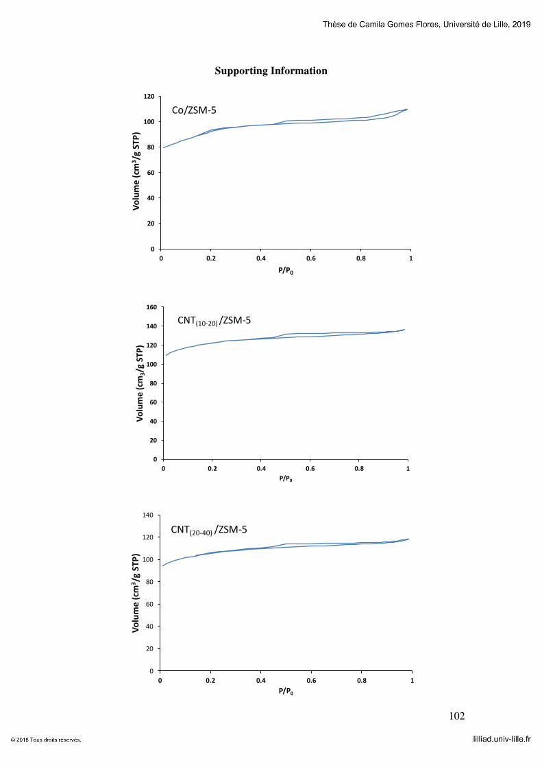
102
Supporting Information
0
20
40
60
80
100
120
0 0.2 0.4 0.6 0.8 1
Vo
lum
e (
cm3/g
ST
P)
P/P0
Co/ZSM-5
0
20
40
60
80
100
120
140
160
0 0.2 0.4 0.6 0.8 1
Vo
lum
e (
cm3/g
ST
P)
P/P0
CNT(10-20) /ZSM-5
0
20
40
60
80
100
120
140
0 0.2 0.4 0.6 0.8 1
Vo
lum
e (
cm3/g
ST
P)
P/P0
CNT(20-40) /ZSM-5
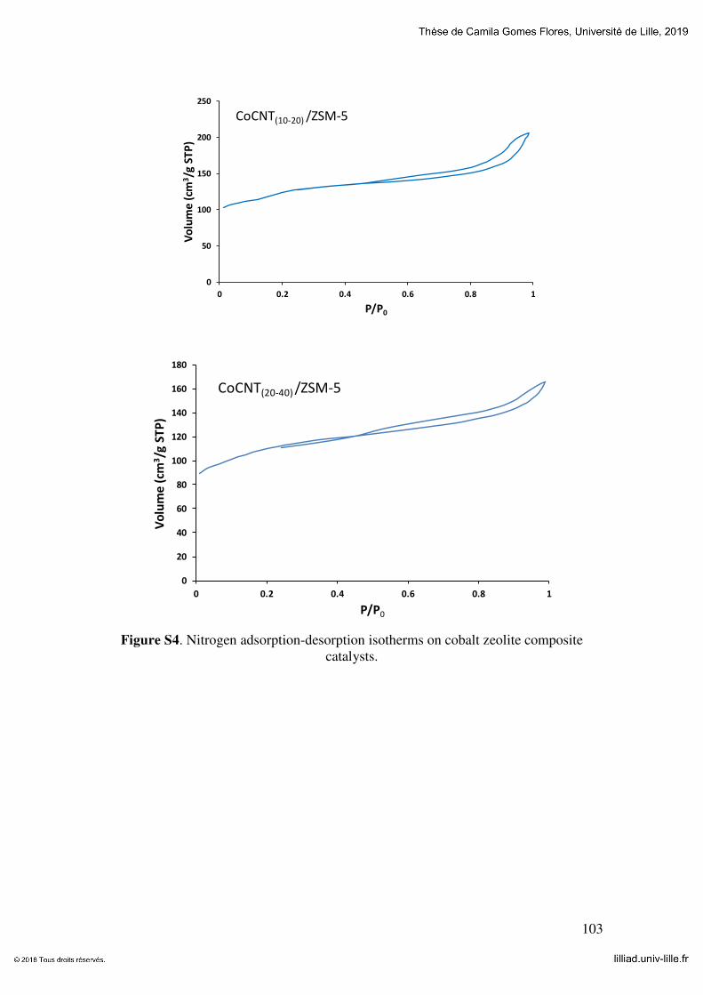
103
Figure S4. Nitrogen adsorption-desorption isotherms on cobalt zeolite composite
catalysts.
0
50
100
150
200
250
0 0.2 0.4 0.6 0.8 1
Vo
lum
e (
cm3/g
ST
P)
P/P0
CoCNT(10-20) /ZSM-5
0
20
40
60
80
100
120
140
160
180
0 0.2 0.4 0.6 0.8 1
Vo
lum
e (
cm3/g
ST
P)
P/P0
CoCNT(20-40) /ZSM-5
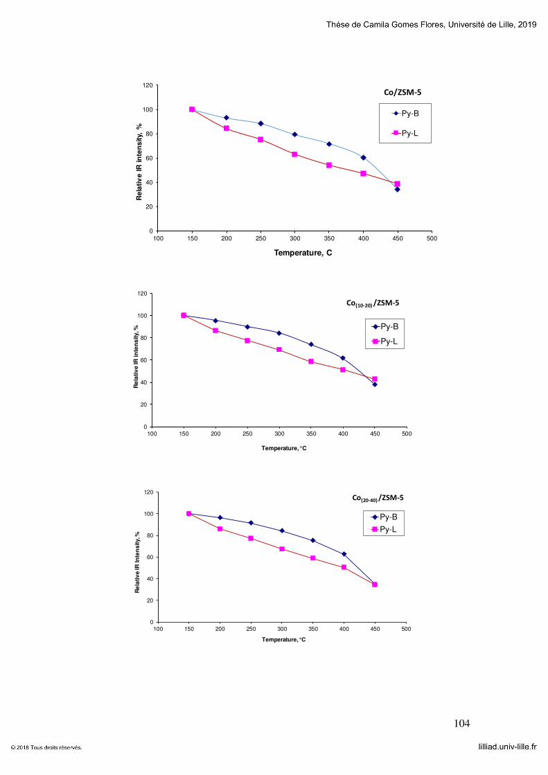
104
0
20
40
60
80
100
120
100 150 200 250 300 350 400 450 500
Re
lati
ve
IR
in
ten
sit
y, %
Temperature, C
Py-B
Py-L
Co/ZSM-5
0
20
40
60
80
100
120
100 150 200 250 300 350 400 450 500
Re
lati
ve
IR i
nte
ns
ity, %
Temperature, °C
Py-B
Py-L
Co(10-20) /ZSM-5
0
20
40
60
80
100
120
100 150 200 250 300 350 400 450 500
Re
lati
ve
IR
In
ten
sit
y, %
Temperature, °C
Py-B
Py-L
Co(20-40) /ZSM-5

105
Figure S5. Variation of intensities of IR bands attributed to Pyridine adsorbed on Brönsted and Lewis acid sites as functions of desorption temperature on different
cobalt-zeolite catalysts. The zeolites synthetized using CNT impregnated with cobalt have slightly stronger Brönsted acid sites compared to the samples prepared by
impregnation.
0
20
40
60
80
100
120
100 150 200 250 300 350 400 450 500
Re
lati
ve
IR
In
ten
sit
y, %
Temperature, °C
Py-B
Py-L
CoCNT(10-20) /ZSM-5
0
20
40
60
80
100
120
100 150 200 250 300 350 400 450 500
Re
lati
ve
IR i
nte
ns
ity, %
Temperature, °C
Py-B
Py-L
CoCNT(20-40) /ZSM-5

106
Figure S6. ASF distribution plot for the wax products obtained from the FT synthesis reaction.
-10
-9
-8
-7
-6
-5
-4
-3
-2
-1
0
5 7 9 11 13 15 17 19 21 23 25 ln
(Wn/n
)
Carbon Number
Co/ZSM-5
Co(10-20)/ZSM-5
Co(20-40)/ZSM-5
CoCNT(10-20)/ZSM-5

107
Chapter 5: Multifaceted Role of Metal Carbon Nanotube Templates in the Synthesis
of Hierarchical Zeolite Composite Catalysts
Manuscript submitted for publication
Abstract: Metal zeolite nanocomposites are extensively used in heterogeneous catalysis.
Small zeolite pore size and non-uniform distribution of the metal component within the
zeolite structure heavily reduce the efficiency of these catalysts. In this work, we propose
a new strategy for the design of hierarchical zeolites with specific shape, enhanced
mesoporosity and uniform distribution of highly dispersed metals such as cobalt, nickel,
and magnesium in the zeolite crystals. The strategy involves using metal carbon
nanotubes as structure directing agents. Multiple roles of the metal carbon nanotubes in
the zeolite synthesis are uncovered. First, they serve as a replica to create zeolite with
specific fibrous shape. Second, they fulfill the role of a mesoporogen and increase 3-5
times the zeolite secondary porosity. Finally, they operate a vehicle to uniformly
introduce the metal functions inside the mesoporous zeolites. Importantly, the presence
of metals in carbon nanotubes is essential for the enhancement of mesoporosity. The
catalysts prepared using metal carbon nanotube templates have shown enhanced catalytic
performance in Fischer-Tropsch synthesis, hydrogenation of aromatics and anisole
acylation.
Keywords: hierarchical zeolite; hard template; replicas; catalyst; promotion; metal
dispersion; acidity

108
5.1 Introduction
Zeolites are microporous crystalline solids with a regular pore system, which have
found numerous applications in industrial processes such as oil refining, organic
synthesis, adsorption and separation. The zeolite crystal structure determines the size and
geometry of the micropores. They are very specific for a given type of the zeolite [1] and
often are comparable with the size of reacting molecules. Smaller and uniform pores lead
to stronger interaction between the zeolite and reacting molecules and thus, introduce
geometric, electronic confinement and shape selectivity phenomena for a catalytic
reaction involving bulky molecules [2]. Zeolites can be tailored to specific catalytic
applications by controlling Brönsted and Lewis acidity as well as by introducing new
catalytic functions, including metal cations, clusters, metal oxides, organic complexes
and enzymes.
Zeolites in their hydrogen form are considered as acid catalysts, while metal-
containing zeolites are considered as bifunctional catalysts that exhibit complex behavior.
The concentrations and intrinsic activity of the metal and acid sites, and in particular, their
localization within the zeolite structure are of utmost importance for the catalyst activity,
selectivity and stability [3-5]. Ion exchange, impregnation, or introduction of a metal
precursor to the zeolite synthesis gel have been often used for synthesis of metal-zeolite
composites. In the metal-zeolite composites, metal can be present either in the form of
isolated cations in the cationic sites, or in the form of tetrahedrally coordinated cations
isomorphously substituting silicon or aluminum atoms in the zeolite framework, or
finally, as small metal or oxide nanoparticles localized within the zeolite micro- or
mesopores. The distribution of metal component with the zeolite is of paramount
importance for the resulting catalytic performance. The distance between metal

109
nanoparticles and acid sites, “site intimacy” [6], diffusional limitations for the
intermediates during their transport from one site to another [7-10] strongly affect the
performance of many catalytic reactions
Very small pore size of zeolites (~1 nm) imposes diffusional limitations for many
catalytic reactions, in particular for those, involving bulky molecules. In order to
overcome these, numerous efforts have made to synthesize nano-sized zeolite crystals [11],
extra-large pore zeolites [12], or mesoporous zeolites [13, 14], the latter are often referred as
hierarchical zeolites. The hierarchical zeolites contain, in addition to the well-defined
micropore system, mesopores with the diameters in the range of 2-50 nm [15, 16]. Different
to zeolite micropores, the size, shape and orientation of these mesopores are not directly
related to the zeolite crystalline structure. The methods used for the preparation of
hierarchical zeolites could be summarized into two main groups. (i) Bottom-up methods,
where sacrificial templates of desired size and dimensions are incorporated into zeolite
crystals during the crystallization step. These templates are then eliminated by
combustion or extraction. (ii) Top-down methods, including post-synthesis chemical
treatment of zeolite crystals leading to the extraction of aluminum and silicon atoms and
partial dissolution of the zeolite framework. Note that it is usually much more difficult to
maintain zeolites with good crystallinity and to generate uniform mesopores using top-
down methods such as steam treatment, acid and alkaline leaching [17] compared to the
bottom-up strategies.
Both hard [18, 19] and soft templates [20, 21] have been utilized to synthetize
hierarchical zeolites using the bottom up approach. The hard templates usually include
carbon nanoparticles, nanotubes and polymer beads, while various cationic surfactants,
organosilane, cationic polymer, and ionic liquids [22, 23] are considered as soft secondary

110
templates. Both hard and soft templates could be removed by calcination. Among the hard
templates, carbon nanotubes (CNT) have attracted particular attention in the literature.
CNT are very versatile materials [24, 25] as their properties are strongly affected by the
presence of hydrophobic or hydrophilic functional groups, metals, oxide and other
dopants. As a result, the properties of hierarchical zeolites prepared using CNT as
secondary templates are strongly affected by the features of CNT and zeolite synthesis
conditions. To the best of our knowledge, no studies have been performed to evaluate the
effect of different metals present in CNT on the zeolite crystallization and mesoporosity.
In this chapter, metal containing CNT (Me-CNT) were applied as secondary
templates for synthesis of hierarchical ZSM-5 zeolites. We uncovered at least three roles
of Me-CNT in the zeolite synthesis. First, they strongly affect the shape of the synthesized
zeolites, which seem to be replicas of CNT and show distinct fibrous texture. Second, the
Me-CNT plays a role of mesoporogen and strongly enhance the zeolite mesoporous
volume. Finally, zeolite synthesis in the presence of Me-CNT offers the opportunity to
simultaneously introduce new catalytic functions leading to bifunctional metal-zeolite
catalysts. The introduced metals are then uniformly distributed within the zeolite crystals.
The presence of metal species in CNT is essential to obtain the observed phenomena.
Note that only very limited impact on zeolite porous structure was observed by using
metal-free CNT as secondary hard templates. The metal zeolite composites prepared
using metal-CNT templates exhibited improved catalytic performance in Fischer-Tropsch
synthesis, hydrogenation of aromatics and anisole acylation with hexanoic acid.

111
5.2 Experimental
CNT and their impregnation with metal precursors
Two multi-wall CNT samples (Iolitec nanomaterial, 95%) with different
diameters, i.e. 10-20 nm and 20-40 nm, were used. The CNT were pretreated with nitric
acid to remove all metal contaminations. This treatment also converted CNT into their
hydrophilic forms. Typically, 3 g of CNT were pretreated in 210 mL of concentrated
HNO3 (68%) for 14 h under reflux. Next, the samples were filtered, washed with distilled
water until pH = 7 and dried at 100 ºC overnight.
Metals were added to CNT via the wet impregnation method using Co(NO3)2
6H2O (Sigma-Aldrich) and Pt(NH3)4(NO3)2 (Sigma-Aldrich), Mg(NO3)2 6H2O (Sigma-
Aldrich) and Ni(NO3)2 6H2O (Sigma-Aldrich) as precursors. Co-impregnation with
platinum was solely used for the preparation of cobalt catalysts. Typically, the precursor
amount for impregnation was calculated to obtain 20 wt.% of the metal in the final
catalyst. The mixture was subjected to ultrasonic treatment for 30 min and dried at 80 °C.
The samples were calcined at 400 °C for 4 h under nitrogen atmosphere.
After calcination in nitrogen, the hydrophilic properties of CNT were partially
lost. In order to restore the CNT hydrophilicity, the samples were treated with H2O2.
Typically, 30 mL of 1:1 H2O2 (Sigma-Aldrich, 35%) and distilled water mixture were
added to 2.56 g of impregnated CNT, sonicated for 30 min and dried at 80 °C. The metal
supported CNT catalysts are denoted as Metal/CNT(x) (where Metal=Co, Ni or Mg) and
x is the CNT diameter in nm.
Synthesis of hierarchical metal-ZSM-5 zeolites

112
The ZSM-5 zeolite was synthesized by using a synthesis gel with the initial
composition of 2.7NaCl:1Al2O3:12.5TPAOH:55.8SiO2:7500H2O. The synthesis of the
zeolite was carried out by mixing sodium chloride (0.380 g, Janssen Chimica, P.A.),
tetrapropylammonium hydroxide (3.0 g, Sigma-Aldrich, 1 M in H2O), sodium aluminate
(0.040 g, Sigma-Aldrich) and distilled water until a clear solution was obtained.
Metal/CNT (0.24 g) and tetraethyl-orthosilicate (TEOS, 2.8 g, Sigma-Aldrich, 99%) were
added to the previous solution. Then, the synthesis gel was aged for 1 h at room
temperature under stirring. The synthesis gel was put inside a Teflon-lined autoclave
(40 mL). The zeolite crystallization was performed under static condition at 170 °C for
24 h. After cooling down, the solid was recovered by filtration and washed until pH=7
was achieved. The final solid was calcined at 600 °C for 4 h in air. Further details relevant
to the introduction of cobalt with CNT into ZSM-5 zeolite are available elsewhere [26].
For comparison, the zeolite syntheses using pure CNT were performed under the
same conditions using a similar gel composition. The resulting zeolites were then
impregnated using incipient wetness method with cobalt, nickel and magnesium nitrates
as precursors.
In order to obtain the zeolite acid form, two successive exchanges using 2 M
NH4NO3 aqueous solution at 80 °C for 1 h (1 g of zeolite per 50 mL of solution) were
performed. The ammonium forms were converted into the protonic forms by calcination
at 450 °C for 4 h in air. The synthesized samples were denoted as: MetalCNT(x)/ZSM-5
(where Metal= Co, Ni or Mg) for the samples synthesized using metal impregnated CNT
(x represents the CNT diameter used in the synthesis, i.e. 10-20 or 20-40 nm) and
CTN(x)/ZSM-5 for the samples synthesized with pure CNT as secondary templates.
Metal/ZSM-5 stands for the zeolite synthetized without any secondary template and

113
conventionally impregnated after its synthesis with a metal nitrate followed by the nitrate
decomposition via calcination in air at 500 °C.
Catalyst characterization
The textural properties of the samples were determined by N2 physisorption on a
Micromeritics ASAP 2000 apparatus. Prior to the analysis, the samples were degassed
under vacuum (10 µmHg) at 350 °C for 4 h. The total pore volume (TPV) was calculated
from the amount of vapor adsorbed at a relative pressure P/P0 = 0.97. The sample surface
area was estimated by the BET method, while the micropore volume was calculated using
the deBoer t-plot method.
The samples were characterized by X-ray diffraction (XRD) with a D8 advance
diffractometer equipped with an energy dispersive type detector and a monochromatic
CuKα radiation source. The samples were analyzed using a step of 0.02° with an
acquisition time of 0.5 s.
The sample chemical composition was determined by X-ray fluorescence (XRF)
using a M4 TORNADO (Bruker) spectrometer. This instrument was equipped with 2
anodes a rhodium X-ray tube 50 kV/600 mA (30 W) and a tungsten X-Ray tube 50
kV/700 mA (35 W). For sample characterization, the rhodium X-ray tube with a poly-
capillary lens enabling excitation of an area of 200 μm was utilised. A Silicon-Drift Si(Li)
detector with Peltier cooling (253°K) and a resolution <145 eV at 100000 cps (Mn Kα)
was used. The measurements were conducted under vacuum (20 mbar). Quantitative
analysis was carried out using fundamental parameter (FP) (standardless).
The catalyst reducibility was studied using an Autochem II (Micrometrics)
temperature-programmed reduction (TPR) system. The samples were reduced under a
flow of 5 % H2 in argon (50 mL/min) and heated up to 800 °C at a rate of 5 °C/min. The

114
catalyst Brönsted and Lewis acidities were monitored by infrared spectroscopy (IR) with
pyridine adsorption. The IR spectra were recorded using a Thermo iS10 spectrometer
(DTGC detector, 64 scans at 4 cm-1 resolution). The samples were pretreated under
vacuum (10-5 Torr) at 450 °C for 5 h. After pre-treatment, pyridine was adsorbed on the
sample and the sample was then heated under vacuum (10-5 Torr) at 150 °C. The spectra
before and after the Py adsorption were collected at ambient temperature. The amounts
of Brönsted and Lewis acid sites were calculated using the intensity of bands at ~1545 cm-
1 and ~1455 cm-1, respectively. The absorption coefficients ε(B)=1.08 for Brönsted acid
sites (peak at ~1545 cm-1) and ε(L)=1.71 cm mol-1 for Lewis acid sites (peaks at ~1455-
1445 cm-1) were used for quantification of the zeolite acid sites.
The TEM observations of the samples were obtained by using a Jeol 2100F
instrument operated at 200 kV. Before the analysis, the samples were dispersed by
ultrasound in ethanol for 5 min, and a drop of the suspension was deposited onto a carbon
membrane on a 300 mesh copper grid. The STEM-HAADF tomographic analysis was
carried out on a Jeol 2100F (field emission gun) microscope operating at 200 kV by using
a spot size of 1.1 Å with a current density of 0.5 pA Å-1. Selected Area Electron
Diffraction (SAED) patterns were recorded using a US1000XP CCD camera with an
exposure time of 2 s on circular areas of 200 nm diameter.
Catalytic tests
Hydrogenation of aromatics: Toluene or triisopropylbenzene hydrogenations were
carried out in a fixed-bed reactor. The catalyst (50 mg) was loaded in the stainless-steel
reactor and then activated in a H2 gas flow (10 cm3/min, atmospheric pressure) at 400 C
for 4 h with a heating rate of 2 °C/min. The reactor was cooled below to 50 °C, a
hydrogen flow with a pressure of 20 bar was introduced into the reactor. The temperature

115
was raised at 1 °C/min to the required reaction temperature (250 °C). The liquid reagents
(toluene or triisopropylbenzene) were injected by pump (PHD ULTRA 4400, Harvard
Apparatus) with a flow rate (0.8 mL/h). The products were collected in a cold tap and
analyzed by a gas chromatograph (Bruker GC-450) equipped with thermal conductivity
(TCD) and flame ionization (FID) detectors.
Fischer Tropsch synthesis: the experiments were performed in a fixed-bed reactor.
Prior to testing, the samples were reduced in situ in pure H2 flow (3 cm3/min) at 400 °C
for 4 h with a heating rate of 3°C/min. After the reactor was cooled down to room
temperature, the flow was switched to syngas (H2/CO = 2) and the pressure adjusted to
20 bar. Nitrogen (5% relative to CO) was used as the internal standard. After achieving
the desired pressure, the temperature was increased to the reaction temperature, i.e.
250 °C, at a rate of 3 °C/min. The gas space velocities were adjusted to obtain CO
conversion of 30-40% for all catalysts. The gaseous reaction products, i.e. up to C5, were
analyzed on-line using a GC equipped with a FID and a TCD detectors (Varian, CP-
3800). The remaining products (wax) were condensed under pressure and analyzed ex
situ on a Shimadzu GC with FID (2010-Plus-AF).
Anisole acylation: the activity of all catalysts was evaluated in the acylation
reaction between anisole and hexanoic acid according to the following protocol. The
catalyst (20 mg) was added to a mixture of anisole (2 g) and hexanoic acid (0.3 g) in a
reflux reactor system. Upon sealing, the tube was heated at 180 °C for 2 h. The products
were analyzed by gas chromatography.
5.3 Results and Discussion
The nitrogen adsorption–desorption isotherms for the catalysts prepared by
impregnation and synthesized using the Me/CNT templates are shown in Figure 5-1.

116
Figure 5-1 Low temperature nitrogen adsorption-desorption isotherms on the HZSM-5
zeolite synthetized with and without addition of CNT (a) cobalt (b), nickel (c) and magnesium (d) ZSM-5 catalysts.
The ZSM-5 sample displays a type-I isotherm exhibiting a sharp uptake at low
relative pressure followed by a plateau with a hardly visible hysteresis at P/P0>0.5. This
type of isotherm is usually observed for microporous materials with textural mesoporosity
generated by aggregation of small zeolite crystallites. Similar isotherms shapes were
observed for the CNT(10-20)/ZSM-5 and CNT(20-40)/ZSM-5 samples synthetized using pure
CNT as secondary hard templates (Figure 5-1a). Table 5-1 shows that the addition of pure
CNT(10-20) during the ZSM-5 zeolite synthesis results in a slight increase in the BET
surface area and pore volume. The use of CNT(20-40) during the ZSM-5 zeolite synthesis
did not change substantially the porous characteristics of the zeolite.
0
50
100
150
200
0 0.2 0.4 0.6 0.8 1
Vo
lum
e a
dso
rbed
(cm
3/g
)
P/P0
CNT(10-20)/ZSM-5
CNT(20-40)/ZSM-5
HZSM-5
a
0
50
100
150
200
0 0.2 0.4 0.6 0.8 1
Vo
lum
e a
dso
rbed
(cm
3g
-1)
P/P0
CoCNT(10-20)/HZSM-5
CoCNT(20-40)/HZSM-5
HZSM-5
Co/HZSM-5
b
0
50
100
150
200
0 0.2 0.4 0.6 0.8 1
Vo
lum
e a
dso
rbed
(cm
3g
-1)
P/P0
NiCNT(10-20)/HZSM-5
NiCNT(20-40)/HZSM-5
HZSM-5
Ni/HZSM-5
c
0
50
100
150
200
250
0 0.2 0.4 0.6 0.8 1
Vo
lum
e a
dso
rbed
(cm
3g
-1)
P/P0
MgCNT(10-20)/HZSM-5
MgCNT(20-40)/HZSM-5
HZSM-5
Mg/HZSM-5
d

117
Table 5-1. Catalyst characterization data
Sample SBET
(m2g-1)
Vtot
(cm3g-1)
Vmic
(cm3g-1)
Vmeso
(m2g-1)
Metal content
(wt%)
Lewis
(µmolg-
1)
Brönsted
(µmolg-1)
ZSM-5 425 0.19 0.13 0.06 - 36 314
CNT(10-20)/ZSM-5 460 0.21 0.15 0.06 - - -
CNT(20-40)/ZSM-5 397 0.18 0.13 0.05 - - -
Co/ZSM-5 372 0.17 0.11 0.07 15.6 530 160
CoCNT(10-20)/ZSM-5 435 0.32 0.09 0.23 7.8 180 250
CoCNT(20-40)/ZSM-5 395 0.25 0.09 0.16 9.4 130 295
Mg/ZSM-5 399 0.18 0.12 0.06 1.5 284 92
MgCNT(10-20)/ZSM-5
433 0.34 0.07 0.27 2.3 48 204
MgCNT(20-40)/ZSM-5 410 0.35 0.05 0.30 2.1 39 141
Ni/ZSM-5 406 0.19 0.11 0.08 5.0 172 179
NiCNT(10-20)/ZSM-5 444 0.29 0.12 0.17 4.5 47 267
NiCNT(20-40)/ZSM-5 434 0.23 0.10 0.13 4.6 18 220
The introduction of metals (Co, Mg, Ni) to the zeolite synthesis gel, without using
CNT as a secondary template, has only a minor effect on the zeolite porosity and specific
surface area resulting in a decrease in the zeolite pore volume and specific surface area
(Table 5-1). The difference between the surface area and pore volume of the parent zeolite
and its counterparts containing metals may be assigned to both, the effect of zeolite
“dilution” by metals and partial pore blocking by the metal species. Only the microporous
zeolite volume is affected by impregnation with metals in Co/ZSM-5, Ni/ZSM-5 and
Mg/ZSM-5 as compared to the parent ZSM-5 zeolite, while almost no changes are
observed in the mesoporous volume. This fact indicates that the metal cations are
preferentially located in the zeolite micropores, whereas the major part of the metal
species, e.g. metal oxides, in the case of ZSM-5 is located on the zeolite external surface.

118
Remarkably, rather different isotherms and textural properties were observed for
the ZSM-5 zeolites synthetized in the presence of Me/CNT templates. The zeolites
prepared in the presence of Co/CNT, Ni/CNT and Mg/CNT templates exhibit a
combination of type I and IV isotherms with a significant N2 uptake at low relative
pressure and a hysteresis loop at high relative pressure (P/P0 > 0.5, Figure 5-1b-d).
Adsorption of nitrogen in the range of P/P0 = 0.5 - 1.0 and relevant hysteresis can be
explained by mesoporosity developed by the presence of cobalt, nickel or magnesium
oxides supported on CNT. Note that almost no increase in the zeolite mesoporosoity was
observed when pure CNT(10-20) or CNT(20-40) were used as mesoporous hard templates
(Table 5-1). Importantly, the presence of metal species on CNT is essential for the
synthesis of ZSM-5 zeolite with enhanced mesoporous volume. A slight increase in the
BET surface area was also observed for CoCNT(10-20)/ZSM-5, NiCNT(10-20)/ZSM-5 and
MgCNT(10-20)/ZSM-5, while the BET surface area slightly decreases when using the
Me/CNT(20-40) templates. Thus, the most significant effect of using CNT containing
cobalt, nickel and magnesium is the substantial increase in the mesoporous volume. The
zeolite mesoporous volume increases 2.5-4 times, when using CoCNT(10-20) and
Co/CNT(20-40), 4.5-5 times, when using MgCNT(10-20) and MgCNT(20-40) and 2.2-3 times
for NiCNT(10-20) and NiCNT(20-40) (Table 5-1). Note that the zeolite micropore volume
(between 0.09-0.13 cm3/g) is only slightly affected by CNT supported metals used as
secondary templates.

119
Figure 5-2 displays XRD patterns of all samples included in the present study. The
characteitic XRD peaks of the MFI structure are observed in all samples, regardless of
the employed synthesis procedure. No halo peaks, which can be attributed to the
amorphous phase, have been observed. Note that the presence of metals in the catalysts
leads to somewhat lower intensity of the zeolite XRD patterns, which is due to the dilution
of the MFI phase with the metal oxides. In the Co/ZSM-5, CoCNT(10-20)/ZSM-5 or
CoCNT(20-40)/ZSM-5 samples a peak at 36.9 ° which is characteritic to the Co3O4 can be
observed. The particle size of Co3O4 calculated using the Scherrer equation (Table 5-1)
was 27-44 nm. Such large size suggests that the main fraction of cobalt oxide is located
either in large mesopores or on the zeolite external surface. The Ni/ZSM-5 catalyst
prepared using impregnation with nickel nitrate showed a very low intense XRD peaks at
43.2° attributed to the face-centered cubic phase NiO (JCPDS card no. #47-1049). The
Ni/CNT(10-20)/ZSM-5 or Ni/CNT(20-40)/ZSM- catalysts prepared using Ni/CNT(10-20) and
Ni/CNT(20-40) as hard templates did not show any peaks characteristic of the nickel oxide
phases. No XRD peaks assigned to the Mg-containing phases were detected in either
Mg/ZSM-5 prepared via aqueous impregnation or in MgCNT(10-20)/ZSM-5 and
MgCNT(20-40)/ZSM-5 catalysts prepared using hydrothermal synthesis with the Mg/CNT
hard template. The absence of XRD peaks attributed to the metal oxide phases can be
explained by smaller metal oxide particle size in the Mg- and Ni-containing samples,
which are below the XRD detection limits.

120
Figure 5-2 XRD patterns of the metal ZSM-5 catalysts.
Figure 5-3 shows the TEM images of the Co, Ni and Mg containing ZSM-5
catalysts prepared using metal-CNT templates. They are very different from those usually
observed for the conventional ZSM-5 zeolite. The zeolite crystallites obtained in the
presence of metal CNT templates exhibit a rather irregular fibrous shape leading to the
development of zeolite mesoporosity. TEM images suggest zeolite crystallization over
CNT. This shape arises from CNT partially encapsulated inside the zeolite crystals during
the zeolite synthesis. The synthesized zeolite seems to replicas of Me/CNT. They
reproduce almost exactly the shape of the secondary templates. Importantly, the presence
of metal containing CNT seems indispensable for obtaining these fibrous zeolite
crystallites. The TEM images for all prepared metal-zeolite catalysts also display small
metal oxide nanoparticles with the diameter between 1 and 5 nm.
5 15 25 35 45 55 65
2θ
ZSM-5
Co/ZSM-5
CoCNT(10-20)/ZSM-5
CoCNT(20-40)/ZSM-5
Mg/ZSM-5
MgCNT(10-20)/ZSM-5
MgCNT(20-40)/ZSM-5
Ni/ZSM-5
NiCNT(10-20)/ZSM-5
NiCNT(20-40)/ZSM-5

121
Figure 5-3 TEM images of CoCNT(10-20)/ZSM-5 high magnification(A), CoCNT(20-
40)/ZSM-5 high magnification (B), MgCNT(10-20)/ZSM-5 (C) and NiCNT(20-40)/ZSM-5 (D).
The presence of zeolite phase in these fibrous structures was further confirmed by
selected area electron diffraction (SAED). Figure 5-4 displays well defined diffraction
patterns and clearly indicates zeolite crystalline phase in the areas containing a larger
quantify of fibrous zeolite replicas of the Me/CNT templates.
100 nm100 nm
20 nm
A B

122
Figure 5-4 TEM image and SAED patterns of NiCNT(20-40)/ZSM-5 zeolite.
STEM-HAADF electron tomography of the CoCNT(20-40)/ZSM-5 sample has
confirmed localization of metal oxide nanoparticles within the zeolite (Figure 5-5). Co
nanoparticles have been observed as bright spots with diameter in the range 2-5 nm.
STEM-HAADF images show that nanoparticles are located inside the pores of CoCNT(20-
40)/ZSM-zeolite. Thus, electron microscopy, electron diffraction and tomography in
combination with other characterization techniques revealed the important role of small
metal oxide clusters in CNT for the formation of mesopores in zeolite crystals. Note that
no noticeable enhancement of the zeolite mesoporosity was observed by using metal-free
CNT as secondary templates (Table 5-1).

123
Figure 5-5 STEM-HAADF electron tomography analysis of CoCNT(20-40)/ZSM-5 catalyst clearly showing the presence of cobalt nanoparticles inside the zeolite structure.
The ZSM-5 zeolite nucleation seems to occur on the metal oxide sites located on
CNT and results in the hierarchical zeolites with enhanced mesoporosity. The resulting
zeolite replicates the fibrous shape of CNT. The mesopores are created when CNT are
removed from the zeolite by calcination. A scheme illustrating the formation of
hierarchical zeolite during the synthesis utilizing Me/CNT as secondary hard templates is
shown in Figure 5-6. It is important to emphasize that the stability of metal oxide
nanoparticles supported on CNT in the basic medium used for zeolite synthesis is
essential for obtaining hierarchical zeolites with enhanced mesoporosity. Our
experiments with templates on the basis of iron and copper oxides supported on CNT did

124
not result in the zeolites with enhanced mesoporosity. This seems to be a consequence of
the dissolution of iron and copper oxides in basic medium during zeolite synthesis.
Figure 5-6 Synthesis of hierarchical zeolites using metal oxide supported on CNT as
secondary hard templates.
Cobalt and nickel temperature programed reduction (TPR) profiles are presented
in Figure 5-7. The reduction patterns of the cobalt zeolite catalysts are consistent with the
presence of several types of cobalt species and two-step Co3O4 reduction to metallic
cobalt. Previous reports [27-29] suggest that Co3O4 is first reduced to CoO at a lower
temperature, whereas CoO is reduced to metallic Co at higher temperatures (Figure 5-7a).
The Co/ZSM-5 sample with cobalt added by impregnation exhibits a TPR peak at 280°C
with shoulders at 150-220 °C. The shoulders at 150-220 °C in the TPR profile of
Co/ZSM-5 can be therefore attributed to the reduction of the Co3O4 nanoparticles to CoO,
while the major TPR peak at 280°C corresponds to the reduction of CoO to metallic
cobalt. Previously we showed that the ZSM-5 catalysts prepared by impregnation
contained a large fraction of cobalt oxide nanoparticles on the zeolite outer surface.
Because of a larger solvating shell, diffusion of multi-charged ions such as cobalt or
nickel, inside the ZSM-5 micropores can be rather slow [30]. In all catalysts prepared by
impregnation, a considerable amount of bivalent metal ions are present on the zeolite
Me/CNT
Metal oxide
nanoparticles
supported on
CNT
Zeolite
crystallized
over Me/CNT
Mesoporous zeolite
replica of CNT with
uniform distribution of
metal oxide
nanoparticles
Zeolite synthesis Oxidative treatment

125
external surface. The CoCNT(10-20)/ZSM-5 and CoCNT(20-40)/ZSM-5 samples exhibited
two groups of TPR peaks at 150-420 °C and at 600 – 800 °C. Similar to the Co/ZSM-5
zeolite, the low temperature peaks are attributed to the reduction of small Co3O4
nanoparticles to metallic cobalt via intermediate formation of CoO. The shift of these
peaks to higher temperature can be explained by smaller Co3O4 particle sizes [31] and their
localization inside the zeolite meso- and micropores. In agreement with previous studies
[32, 33], the peaks at higher temperature are assigned to cobalt silicates or aluminates. These
mixed compounds form because of the interaction and chemical reactions between the
small metal oxide nanoparticles located on CNT and zeolite synthetized under the
hydrothermal conditions. The TPR data are consistent with the suggestions that cobalt
species supported on CNT act as nucleation sites in the synthesis of the hierarchical ZSM-
5 zeolite.
0 100 200 300 400 500 600 700 800
Temperature (°C)
Co/ZSM-5CoCNT(20-40)/ZSM-5
CoCNT(10-20)/ZSM-5
Ni/ZSM-5
NiCNT(20-40)/ZSM-5
NiCNT(10-20)/ZSM-5
Figure 5-7 Temperature programmed reduction (TPR) profiles of the Co (a) and Ni (b)
catalysts.

126
The reduction profiles of the nickel catalysts prepared by impregnation with nickel
nitrate and synthetized using Ni/CNT as secondary templates are shown in Figure 5-7b.
They exhibit broad hydrogen consumption peaks in the temperature range from 350 to
750°C. A single hydrogen consumption peak at about 400°C [34, 35] is usually observed in
the TPR profile of bulk NiO. It corresponds to the reduction of NiO to metallic nickel.
Thus, the low temperature peaks located between 400 and 500°C in the TPR profiles of
nickel-zeolite catalysts may correspond to the reduction of small NiO particles. Note that
the Ni/ZSM-5 zeolite prepared by impregnation usually contains a significant
concentration of NiO on the zeolite outer surface. These NiO nanoparticles are detected
in Ni/ZSM-5 by XRD (Figure 5-2). Similar to cobalt zeolite nanocomposites, the shift of
the TPR peaks to a higher temperature can be due to the smaller NiO particle size and
some diffusional limitations during their reduction arising from the localization of these
small NiO nanoparticles in the porous material [36]. The area of the low temperature TPR
peaks between 400° and 500 °C significantly decreases for the catalysts prepared using
Ni/CNT as secondary templates. This corresponds to the decrease in the concentration of
the NiO particles on the zeolite outer surface. The TPR profiles of the NiCNT(10-20)/ZSM-
5 and NiCNT(20-40)CNT/ZSM-5 catalysts exhibit low intensity peaks at 500-700 °C. High
temperature TPR peaks can be attributed to the reduction of highly dispersed nickel
species [37] or to the presence of nickel silicate (phyllosilicate) species [ 38, 39]. In agreement
with other characterization methods, the TPR results clearly show that introduction of
nickel and cobalt species with CNT during the zeolite hydrothermal synthesis results to
higher metal dispersion. In cobalt catalysts, metal nanoparticle localization within zeolite
meso- and micropores also leads to the formation of mixed compounds between metal
oxide, silica or alumina.

127
The acidity of the metal-zeolite catalysts has been characterized by FTIR using
adsorption of pyridine (Py) as a probe for Brönsted (BAS) and Lewis acid sites (LAS).
The FTIR spectra recorded after Py adsorption on the reduced catalysts are displayed in
Figure 5-8. The pure ZSM-5 zeolite exhibits characteristic bands at ~1545 and 1455-45
cm-1 assigned to the pyridinum ion (PyH+) formed on BAS and to Py adsorbed on LAS
(which may also include metal ions such as Co2+, Ni2+ or Mg2+), respectively. Py adsorbed
on both the LAS and BAS also displays a band at 1490 cm-1. The concentrations of BAS
and LAS calculated using the molar absorption coefficients for the bands at ~1545 and
1455-45 cm-1 are shown in Table 5-1. Impregnation of the ZSM-5 zeolite with Co2+, Ni2+,
and Mg2+ cations leads to a significant decrease in the concentration of BAS. The effect
is more pronounced for the Mg2+ impregnated ZSM-5. A much lower concentration of
BAS in the impregnated catalysts can be explained by the ion exchange of the zeolite
bridging OH group protons with the Mg2+, Ni2+ and Co2+ ions. Small metal oxide clusters
can also block some zeolite microporesthus making some of BAS inaccessible for Py
adsorption. Interestingly, at the same metal content in the zeolites, the decrease in the
concentration of BAS is less significant, when the cations are introduced with the
Me/CNT hard templates. This suggests that a significant fraction of the metal species
added with Me/CNT are probably not localized in the cationic zeolite sites but present as
small oxide clusters in the zeolite micro- and mesopores. This explain a less significant
decrease in the number of BAS in the zeolites synthetized using the Me/CNT hard
templates with the same metal contents.

128
Figure 5-8 FTIR spectra observed after adsorption of Py on cobalt (a), nickel (b) and
magnesium (c) zeolite catalysts
The number of LAS is considerably higher in all metal containing ZSM-5 as
compared to their metal-free ZSM-5 counterpart (Table 5-1). The addition of the metals
results in the generation of news types of Lewis acid sites such as coordinatively
unsaturated Co2+, Ni2+ or Mg2+ cations. Some of these cations can occupy zeolite cationic
sites. Interestingly, a much lower concentration of Lewis acid sites is generated in the
metal zeolite catalysts prepared using zeolite crystallization in the presence of metal CNT
secondary templates as compared to the sample prepared by zeolite impregnation with
nitrates. This can be due to a lower concentration of Co2+, Ni2+ and Mg2+ in the cationic
sites of the hierarchical zeolites. This also indicates the formation of metal oxide clusters
and is consistent with a smaller decrease in the number of BAS in the zeolites prepared
using the Me/CNT hard templates.
1400150016001700
Wavenumbers (cm-1)
ZSM-5Co/ZM-5CoCNT10-20)/ZSM-5CoCNT(20-40)/ZSM-5
a
1400150016001700
Wavenumbers (cm-1)
Ni/ZSM-5
NiCNT(10-20)/ZSM-5
NiCNT(20-40)/ZSM-5
b
1400150016001700
Wavenumbers (cm-1)
Mg/ZSM-5MgCNT(10-20)/ZSM-5MgCNT(20-40)/ZSM-5
c

129
Catalytic Performance in Fischer-Tropsch Synthesis, Hydrogenation and Acylation
Reactions
The results of catalytic tests of cobalt zeolite catalysts in Fischer-Tropsch
synthesis are presented in Table 5-2. Hydrocarbons and water were major reaction
products of carbon monoxide hydrogenation. Extremely small amounts of CO2 were
observed. By varying GHSV between 20 and 70 L/hgCo, the CO conversion of 30 – 40%
was obtained for all catalysts. The reaction rate normalized by the amount of cobalt in the
catalysts slightly increases for CoCNT(10-20)/ZSM-5 and decreases in CoCNT(20-40)/ZSM-
5 compared to the Co/ZSM-5 sample prepared by conventional impregnation. Note
however, that TPR (Figure 5-7a) is indicative of very different cobalt reducibility in
different samples. The addition of the Co/CNT hard templates during the zeolite synthesis
results in the formation of barely reducible cobalt silicate or cobalt aluminate species,
which exhibit TPR peaks at 800-900°C. The peaks at 800-900°C are absent in the TPR
profiles of Co/ZSM-5. This suggests a low concentration of cobalt silicates or aluminates
in the Co/ZSM-5 catalyst prepared by impregnation. Interestingly, the activity per
reducible cobalt increased 5 – 10 times over CoCNT/ZSM-5 prepared using CoCNT as
secondary templates in comparison with Co/ZSM-5 prepared by impregnation. The
methane selectivity varied between 13 – 37%. Previous report [40] suggests that the higher
methane selectivity over zeolite based catalysts can be due to more significant diffusion
limitations for carbon monoxide molecules compared to hydrogen. Slower diffusion of
CO relative to hydrogen results in the CO deficiency the zeolite pores. The resulting
higher H2/CO ratio in the narrow zeolite pores leads to a higher contribution of
methanation reaction and higher methane selectivity. Importantly, lower methane
selectivity was observed over CoCNT(10-20)/ZSM-5 and CoCNT(20-40)/ZSM-5 with larger
mesoporous volume. These catalysts may have less significant diffusion limitations

130
compared to mostly microporous Co/ZSM-5, where cobalt was added by impregnation.
The catalysts prepared using the CoCN5(10-20) and CoCNT(20-40) hard templates also
exhibit a higher selectivity to the C5+ products (around 74%) as compared to the
conventional Co/ZSM-5 catalysts which exhibited C5+ selectivity of 48% (Table 5-2).
Table 5-2. Activity and selectivity of the catalysts for the Fischer-Tropsch synthesis reaction (P=2 MPa, GHSV=20-70 L/hgCo, T=250 °C, H2/CO=2)
Catalyst Activity
(mmolCO/h.gCo)a
Conversion
(%)
Selectivity (mol. C%)
CH4 C2-C4
C2-C4
(olefin) C2-C4
(paraffin)
C2-C4
(P/O) C5
+
Co/ZSM-5 244 39 32.8 19.0 2.7 16.3 6.0 48.1
CoCNT(10-
20)/ZSM-5 352 (1961)b 42 15.9 13.8 2.8 11.0 3.9 73.1
CoCNT(20-
40)/ZSM-5 131 (1893)b 28 12.6 13.2 3.0 10.2 3.4 74.2
[a]Time at 24 h. [b] In brackets: activity in reducible cobalt basis.
Nickel catalysts were tested in the toluene and 1,3,5-triisopropylbenzene
hydrogenation (Table 5-2). These reactions were used to evaluate the activity and
accessibility of nickel metal sites in the hierarchical zeolites. The mesoporosity developed
in the nickel-zeolite catalysts synthetized in the presence of Ni/CNT secondary templates
results in a significantly higher hydrogenation rate in both toluene and 1,3,5-
triisopropylbenzene reactions. The reaction rate increases in the order: Ni/SZM-5<
NiCNT(10-20)/ZSM-5<NiCNT(20-40)/ZSM-5. This is therefore indicative of a better nickel
dispersion and enhanced accessibility of nickel metallic sites in the zeolites prepared
using the Ni/CNT hard templates. Noteworthy, the zeolite prepared using NiCNT(20-40)
with larger CNT diameter exhibited higher reaction rate in both toluene and 1,3,5-
triisopropylbenzene hydrogenation reactions.

131
Table 5-3. Hydrogenation reaction (H2=20 mL/min, Liquid flow=0.8 mL/h T=250 °C, P=20 bar).
Catalyst Toluene
Conversion (%)
1,3,5-Triisopropylbenzene
Conversion (%) Ni/ZSM-5 60 23.7
NiCNT(10-20)/ZSM-5 83.3 50.8
NiCNT(20-40)/ZSM-5 97.7 97
*Time at 6 h.
Zeolites usually contain significant concentration of acid sites. Acylation of
anisole with hexanoic acid was selected as a model reaction to characterize the catalytic
performance of the acid sites on the outer surface and in the mesopores of the hierarchical
zeolites (Figure 5-9).
Figure 5-9 Acylation of anisole with hexanoic acid results in ortho-methoxy-hexyl-phenone.
On all catalysts evaluated in the present work, the reaction results in the formation
of ortho-methoxy-hexyl-phenone with the selectivity higher than 90%, while the
selectivity to the para-isomer was less than 10%. Only traces of the meta-isomer were
detected. Note that the size of the ortho-isomer is much higher than the dimeter of
micropores in the ZSM-5 zeolite. Higher selectivity to the larger size ortho- methoxy-
hexyl-phenone is consistent with the critical role of the zeolite acid sites on the zeolite
outer surface and mesopores in this reaction. The hexanoic acid conversion and reaction
rate are displayed in Table 5-4. For all catalysts, the conversion increases, when Me/CNTs
were added as hard templates during the zeolite synthesis. The conversion increases 2-4

132
times over CoCNT(10-20)/ZSM-5 and CoCNT(20-40)/ZSM-5; 1.3-1.6 times over NiCNT(10-
20)/ZSM-5 and NiCNT(20-40)/ZSM-5 and 4.5 – 5.0 times over MgCNT(10-20)/ZSM-5 and
MgCNT(20-40)/ZSM-5 in comparison with their counterparts prepared via impregnation.
The effect is more pronounced when CNT had a relatively large (20-40 nm) diameter.
The highest conversion was achieved over NiCNT(20-40)/ZSM-5.
Table 5-4. Acylation reaction (2 g of anisol, 0.3 g hexanoic acid, 20 mg of the catalyst, T=180 °C).
Catalyst Conversion (%) Reaction rate (μmol/g min)
Co/ZSM-5 0.43 4.63
CoCNT(10-20)/ZSM-5 1.00 10.78
CoCNT(20-40)/ZSM-5 1.79 19.29
Ni/ZSM-5 1.53 16.49
NiCNT(10-20)/ZSM-5 1.92 20.69
NiCNT(20-40)/ZSM-5 2.46 26.51
Mg/ZSM-5 0.26 2.80
MgCNT(10-20)/ZSM-5 1.18 12.72
MgCNT(20-40)/ZSM-5 1.31 14.12
*time at 2 h.
Figure 5-10 shows the relation between the conversion of hexanoic acid and the
number of Brönsted acid sites in the catalysts. Both the concentration of Brönsted acid
sites and the presence of mesopores created in the ZSM-5 zeolite in the presence of metal
supported CNT affect the catalytic performance in the anisole acylation. Interestingly, at
similar concentration of BAS, the higher acylation rates were observed for the catalysts
with higher mesoporosity. In particular, the CNT diameter is important for preparing the
metal zeolite catalysts with higher reaction rates. The zeolites with larger mesopores
obtained using Me/CNT with the diameter of 20-40 nm were the most active in this
reaction. This suggests a better accessibility of both Brönsted and metal sites in the
hierarchical ZSM-5 prepared using the Me/CNT templates. Hence, the strategy for

133
synthesis of hierarchical zeolites using metal supported CNT as secondary hard templates
seems promising. It produces hierarchical zeolites replicating the shape of CNT with
enhanced mesoporosity and containing highly dispersed, accessible and uniformly
distributed metal and acid sites, which will be certainly beneficial for several important
catalytic reactions.
Figure 5-10 Hexanoic acid conversion in anisole acylation over the metal zeolite catalysts prepared by impregnation and using Me/CNT as secondary hard templates.
5.3 Conclusion
A new synthesis strategy for the preparation of hierarchical zeolites preparation has
been developed. The zeolite crystallites were prepared under hydrothermal conditions in
the presence of CNT supported metal nanoparticles used as secondary hard templates.
The Me/CNT templates play three roles in the synthesis of hierarchical zeolite. These
templates are at the same time (i) a zeolite synthesis replica, (ii) a mesoporogen and (a) a
tool to introduce uniformly distributed metal species into zeolites.

134
The metal oxide species seem to be nucleation sites and crystallization modifier
leading to the fibrous zeolite structures, which largely replicates the CNT. Using Me/CNT
as templates leads a several-fold increase in the zeolite mesoporous volume. In the
synthetized zeolites, the dispersed metal species are uniformly distributed within the
crystallites and mostly present as small metal oxide nanoparticles. The concentration of
Brönsted acid sites in the zeolites synthetized using Me/CNT as secondary templates is
higher than in the zeolites with the same amount of metal species prepared via
impregnation.
Because of a decrease in the diffusion limitations and uniform distribution of metal
nanoparticles in the zeolite, the resulting materials have shown improved catalytic
performance in three catalytic reactions: Fischer-Tropsch synthesis, hydrogenation of
aromatics and anisole acylation.

135
References
[1] Corma, A. From Microporous to Mesoporous Molecular Sieve Materials and Their
Use in Catalysis, Chem. Rev. 1997, 97, 2373-2419.
[2] Egeblad, K.; Christensen, C.H.; Kustova, M.; Christensen, C. H. Templating
Mesoporous Zeolites, Chem. Mater. 2008, 20, 946–960.
[3] Ertl, G.; Knözinger, H.; Weitkamp, J. in Preparation of solid acids, Wiley-VCH,
Germany 1999.
[4] Weisz, P.B. Polyfunctional heterogeneous catalysis, Adv. Catal. 1962, 13, 137-190.
[5] Subramanian, V.; Zholobenko, V.L.; Cheng, K.; Lancelot, C.; Heyte, S.; Thuriot, J.;
Paul, S.; Ordomsky, V.V.; Khodakov, A.Y. The Role of Steric Effects and Acidity in the
Direct Synthesis of iso‐Paraffins from Syngas on Cobalt Zeolite Catalysts,
ChemCatChem 2016, 8, 380-389.
[6] Ertl, G.; Knözinger, H.; Weitkamp, J. in Preparation of solid acids, Wiley-VCH,
Germany, 1999.
[7] Zečević, J.; Vanbutsele, G.; de Jong, K.P.; Martens, J.A. Nanoscale intimacy in
bifunctional catalysts for selective conversion of hydrocarbons, Nature 2015, 528, 247.
[8] Samad, J. E.; Blanchard, J.; Sayag, C.; Louis, C.; Regalbuto, J.R. The controlled
synthesis of metal-acid bifunctional catalysts: The effect of metal:acid ratio and metal-
acid proximity in Pt silica-alumina catalysts for n-heptane isomerization, J. Catal. 2016,
342, 203–212.
[9] Prins, R. Hydrogen Spillover. Facts and Fiction. Chem. Rev. 2012, 112, 2714–2738.
[10] Im, J.; Shin, H.; Jang, H.; Kim, H.; Choi, M. Nat. Commun. 2014, 5, Article number:
3370.
[11] Carvalho, A.; Marinova, M. ; Batalha, N. ; Marcilio, N.R. Khodakov, A.Y.;
Ordomsky, V.V. Design of nanocomposites with cobalt encapsulated in the zeolite

136
micropores for selective synthesis of isoparaffins in Fischer–Tropsch reaction, Catal. Sci.
Technol. 2017, 7, 5019-5027.
[12] Peron, D. V. ; Zholobenko, V.L.; Rodrigues de la Rocha, M.; Oberson de Souza,
M. ; Feris, L.A. ; Marcilio, N.R. ; Ordomsky, V.V. ; Khodakov, A.Y. Nickel–zeolite
composite catalysts with metal nanoparticles selectively encapsulated in the zeolite
micropores, J Mater Sci, 2019, 54, 5399–5411.
[13] Tosheva, L.; Valtchev, V.P. Nanozeolites: Synthesis, Crystallization Mechanism,
and Applications, Chem. Mater. 2005, 17, 2494-2513.
[13] Jiang, J.; Yu, J.; Corma, A. Extra-Large-Pore Zeolites: Bridging the Gap between
Micro and Mesoporous Structures, Angew. Chem. Int. Ed. 2010, 49, 3120 – 3145.
[15] Tao, Y.; Kanoh, H.; Abrams, L.; Kaneko, K. Mesopore-Modified Zeolites:
Preparation, Characterization, and Applications, Chem. Rev. 2006, 106, 896-910.
[16] van Donk, S., Janssen, A.H.; Bitter, J.H.; de Jong, K.P. Generation, Characterization,
and Impact of Mesopores in Zeolite Catalysts, Catal. Rev. Sci. Eng. 2003, 45, 297-319.
[17] Chen, H.; Wang, Q.; Zhang, X.; Wang, L. Hydroconversion of jatropha oil to
alternative fuel over hierarchical ZSM-5. Ind. Eng. Chem. Res. 2014, 53, 19916-19924.
[18] Schmidt, I.; Boisen, A.; Gustavsson, E.; Ståhl, K.; Pehrson, S.; Dahl, S.; Carlsson,
A.; Jacobsen, C. J. H. Carbon Nanotube Templated Growth of Mesoporous Zeolite Single
Crystals, Chem. Mater. 2001, 13, 4416-4418.
[19] Boisen, A.; Schmidt, I.; Carlsson, A.; Dahl, S.; Brorson, M.; Jacobsen, C.J.H. TEM
stereo-imaging of mesoporous zeolite single crystals, Chem. Commun. 2003, 958–959.
[20] Meng, X.; Nawaz, F.; Xiao, F.-C. Templating route for synthesizing mesoporous
zeolites with improved catalytic properties, Nano Today 2009, 4, 292-301.
[21] Zhou, M.; Wang, F.; Xiao, W.; Gao, L.; Xiao, G. The comparison of mesoporous
HZSM-5 zeolite catalysts prepared by different mesoporous templates and their catalytic

137
performance in the methanol to aromatics reaction, Reac Kinet Mech Cat 2016, 119,
699–713.
[22] Zhai, Y.; Zhu, Z.; Dong, S. Carbon-Based Nanostructures for Advanced Catalysis,
ChemCatChem 2015, 7, 2806-2815.
[23] Liu, W.-W.; Chai, S.-P.; Mohamed, A.R.; Hashim, U. Synthesis and characterization
of graphene and carbon nanotubes: A review on the past and recent developments. J. Ind.
Eng. Chem. 2014, 20, 1171-1185.
[24] Flores, C.; Batalha, N.; Ordomsky, V.; Zholobenko, V.L.; Baaziz, W.; Marcilio,
N.R.; Khodakov, A.Y. Direct Production of Iso-Paraffins from Syngas over Hierarchical
Cobalt-ZSM-5 Nanocomposites Synthetized by using Carbon Nanotubes as Sacrificial
Templates, ChemCatChem, 2018, 10, 2291-2299.
[25] van’t Blik, H.F.J.; Prins, R. Characterization of supported cobalt and cobalt-rhodium
catalysts: III. Temperature-Programmed Reduction (TPR), Oxidation (TPO), and EXAFS
of Co-Rh/SiO2. J. Catal. 1986, 97, 210-218.
[26] Hong, J.; Marceau, E.; Khodakov, A.Y.; Griboval-Constant, A.; La Fontaine, C.;
Villain, F.; Briois, V.; Chernavskii, P.A. Impact of sorbitol addition on the structure and
performance of silica-supported cobalt catalysts for Fischer–Tropsch synthesis, Catal.
Today 2011, 175, 528-533.
[27] Khodakov, A.Y.; Griboval-Constant, A.; Bechara, R.; Villain, F. Pore-size control
of cobalt dispersion and reducibility in mesoporous silicas, J. Phys. Chem. B 2001, 105,
9805-9811.
[28] Stakheev, A.Y.; Khodakov, A.Y.; Kustov, L.M.; Kazansky, V.B.; Minachev, K.M.
Localization of polyvalent cations in pentasil catalysts modified by metal oxides. Zeolites
1992, 12, 866-869.

138
[29] Khodakov, A.Y.; Lynch, J.; Bazin, D.; Rebours, B.; Zanier, N.; Moisson, B.;
Chaumette, P. Reducibility of cobalt species in silica-supported Fischer–Tropsch
catalysts, J. Catal. 1997, 168, 16-25.
[30] Puskas, I.; Meyers, B. L.; Hall, J. B. Activity decline and diffusional changes in a
magnesium-promoted cobalt-silica catalyst, Catal. Today 1994, 21, 243–251.
[31] S. Jong, J.; Cheng, S. Reduction behavior and catalytic properties of cobalt
containing ZSM-5 zeolites, Appl. Catal. A 1995, 126, 51–66.
[32] Tomiyama, S.; Takahashi, R.; Sato, S.; Sodesawa, T.; Yoshida, S. Preparation of
Ni/SiO2 catalyst with high thermal stability for CO2-reforming of CH4. Appl. Catal. A
2003, 241, 349-361.
[33] Soghrati, E., Kay, T.; Ong, C.; Kok Poh, C.; Kawi, S.; Borgna, A. Zeolite–supported
nickel phyllosilicate catalyst for CO hydrogenolysis of cyclic ethers and polyols, Appl.
Catal. B 2018, 235, 130-142.
[34] Maia, A.J.; Louis, B.; Lam, Y.L.; Pereira, M.M. Ni-ZSM-5 catalysts: Detailed
characterization of metal sites for proper catalyst design, J. Catal. 2010, 269, 103–109.
[35] Romero, M.D.; de Lucas, A.; Calles, J.A.; Rodriguez, A. Bifunctional catalyst
Ni/HZSM-5: effects of the nickel incorporation method, Appl. Catal. A 1996, 146, 425-
441.
[36] Chen, B.-H.; Chao, Z.-S.; He, H.; Huang, C.; Liu, Y.-J.; Yi, W.-J.; Wei, X.-L.; An,
J.-F. Towards a full understanding of the nature of Ni(ii) species and hydroxyl groups
over highly siliceous HZSM-5 zeolite supported nickel catalysts prepared by a
deposition-precipitation method. Dalton Trans. 2016, 45, 2720-2739.
[37] B.- Chen, B.-H.; Liu, W.; Li, A.; Liu, Y.-J.; Chao Z.-S. A simple and convenient
approach for preparing core–shell-like silica@ nickel species nanoparticles: highly

139
efficient and stable catalyst for the dehydrogenation of 1, 2-cyclohexanediol to catechol,
Dalton Trans. 2015, 44, 1023-1038.
[38] Iglesia, E.; Reyes, S.C.; Madon, R. J. and Soled, S.L. Adv. Catal. 1993, 39, 221-302.

140
Chapter 6: General Conclusion and Perspectives
This thesis was performed at “Unité de catalyse et de chimie du solide” (UCCS),
University of Lille, France, and in the Department of Chemical Engineering, Federal
University of Rio Grando Do Sul, Brazil in 2016-2019. The main objective of this Ph. D.
thesis was to design bifunctional catalysts on the basis of metal nanoparticles and
mesoporous zeolites with the target to enhance their catalytic performance in different
reactions such as Fischer Tropsch synthesis, toluene and 1, 3, 5 triisoproplybenzene
hydrogenation and acylation of anisole. The work followed three parallel and
complementary paths. The first one (Chapter 3) is centered on the study of influence of
impregnation and ion exchange sequence, in particular on the metal localization, acidity
of cobalt supported on the large pore BEA zeolite. The second (Chapter 4) is focused on
the production of iso-paraffins from syngas, more specifically by creating hierarchical
ZSM-5 zeolite using cobalt CNT as sacrificial template. The third (Chapter 5) is aimed
on mesoporosity creation of ZSM-5 using different metals like nickel and magnesium
supported on CNT.
6.1 General Conclusion
In chapter III, four different catalysts prepared using different ion exchange
sequence were synthesized: Co/HBEA, CoH/HBEA, Co/NaBEA, CoH/NaBEA. Cobalt
impregnation on the H-from of BEA results in cobalt localization on the outer surface and
in the zeolite micropores. The deposition of cobalt on the BEA zeolite external surface
and in the micropores leads to cracking and higher methane selectivities in FT synthesis.
The catalyst CoH/NaBEA with the Co species localized on the external surface and high
concentration of Brӧnsted acid sites in the zeolite micropores, showed lower methane

141
selectivity, higher selectivity to long chain hydrocarbons and significant yield of
isomerized hydrocarbons. This strategy seems to have several advantages for the design
of bifunctional catalysts over large pore zeolites.
In chapter IV, the use of the bifunctional Co/ZSM-5 catalysts enhanced the iso-
paraffin selectivity in FT synthesis. This improvement can be attributed by creation of the
mesopores in the ZSM-5 zeolite using metal-CNT as templates. The mesoporosity
increased 3-4 times by introducing Co/CNT during the zeolite synthesis. Besides that,
when cobalt was impregnated in the CNT and then placed in the synthesis gel, the
resulting zeolite had higher amount of Brönsted acid sites. This methodology leads to
more uniform metal distribution on the support and greater proximity between active
metal sites and acid sites from the zeolite. The catalysts prepared using Co/CNT as
secondary templates presented an enhanced selectivity to isomerized branched
hydrocarbons and lower methane selectivity.
In chapter V, the methodology used to create hierarchical zeolite with metal CNT
was extended to other metals like Ni and Mg. The deposed metal particles have uniform
distribution in the crystallites of hierarchical zeolites. Important roles of the metal carbon
nanotubes in the zeolite synthesis are uncovered. First, Me/CNT serve as a replica to
create zeolites with specific fibrous morphology. Second, they fulfill the role of a
mesoporogen and markedly increase the zeolite secondary porosity. Finally, they act as a
vehicle to uniformly introduce the metal functions inside the mesoporous zeolites. The
presence of metals in carbon nanotubes is essential for the enhancement of mesoporosity.
This thesis clearly shows that the catalytic performance of metal zeolite composite
catalysts is a function of zeolite mesoporososity, zeolite pore sizes, zeolite acidity and
localization of metal nanoparticles on the zeolite outer surface or in the zeolite

142
micropores. Because of the decrease in the diffusion limitations and uniform distribution
of metal nanoparticles in the zeolite, the resulting materials have shown improved
catalytic performance in three catalytic reactions: Fischer-Tropsch synthesis,
hydrogenation of aromatics and anisole acylation.
6.2 Perspectives
Thus, efficient control of localization of metal and acid sites within metal zeolite
composite catalysts is a very useful tool to tune the catalytic performance for many
catalytic reactions. The results of this thesis allow us to propose new strategies for the
design of bifunctional catalysts. In particular, two new methodologies can be further
developed such as
- Introducing one metal inside the CNT and another metal outside the CNT when
using Me/CNT as templates for zeolite synthesis. This strategy should reduce formation
of barely reducible metal silicates with the metal species which are located inside CNT;
- Microemulsion methodology which might control the size of metal nanoparticles
deposed inside the micro and mesopores of zeolite and
- Catalyst deactivation is a major challenge for the design of bifunctional catalysts.
Though the catalysts developed in these work were stable in lab scale experiments, further
long duration tests are required to evaluate their stability under industrial conditions.