syngas production via carbon dioxide electroreduction over
TRANSCRIPT

Int. J. Electrochem. Sci., 16 (2021) Article ID: 210369, doi: 10.20964/2021.03.43
International Journal of
ELECTROCHEMICAL SCIENCE
www.electrochemsci.org
Syngas Production via Carbon Dioxide Electroreduction Over
CdS Nanorods
Jinhua Xiong1,*, Xinyu Bi1, Song He1, Changsheng Cao2,*
1 Fujian Provincial Key Laboratory of Clean Energy Materials, Longyan University, Longyan
364000, P. R. China 2 State Key Laboratory of Structural Chemistry, Fujian Institute of Research on the Structural of
Matter, Chinese Academy of Science, Fuzhou 350002, China *E-mail: [email protected], [email protected]
Received: 7 November 2020 / Accepted: 21 December 2020 / Published: 31 January 2021
Herein, CdS nanorods (CdS-NR) was synthesized through a simple and facile solvothermal method.
XRD pattern and TEM/HRTEM images indicated that hexagonal CdS nanorods with a diameter of 10
nm were successfully prepared. When used as electrocatalyst for CO2 reduction reaction (CO2RR),
CdS-NR afforded an excellent electrocatalytic performance in aqueous electrolyte. In comparison with
commercial CdS nanoparticles (CdS-NP), CdS-NR could trigger the electroreduction of CO2 to CO
with a higher faradic efficiency and current densities. The enhanced electrochemical performance of
CdS-NR than that of CdS-NP were ascribed to its enhanced adsorption of CO2, charge transfer ability
and more exposed active sites. More importantly, it was noticed that H2 generated along with CO, and
the generated gas products with controllable ratios exhibited impressive potentials to directly using as
syngas.
Keywords: CdS nanorods, electrocatalysis, CO2 reduction, syngas
1. INTRODUCTION
Syngas, a mixture of CO and H2 with certain ratios, is an indispensable feed gas for the
production of important chemicals like methanol, olefin and alkane [1]. Industrially, syngas is mainly
produced through gasification and natural gas reforming process, which is always an energy and cost
intensive process [2]. Alternatively, syngas production via electrocatalytic CO2 reduction reaction
(CO2RR) in ambient conditions shows a prospectively potentials in the future [3].
Up to now, some electrocatalysts were artfully designed to produce syngas with controllable
ratios of CO and H2. Wen et al. reported that ingenious designing of Cu nanoparticles decorated
reduced graphene oxide achieved the easily production of syngas with a tuneable ratio of H2/CO from

Int. J. Electrochem. Sci., 16 (2021) Article ID: 210369
2
1.16 to 6.38 [4]. Chen and his co-workers found that carefully preparation of Co/Ni single-atom
catalysts with controllable ratio of Co/Ni could produce a high syngas production with CO/ H2 ratios
from 0.23 to 2.26 [5]. Moreover, Yang et al. reported that transition metal like Fe, Co and Ni decorated
Au electrocatalysts was able to control the generation of H2 and CO from aqueous CO2, and thus the
syngas with desirable compositions was achieved [6]. Based on those results, we believe that
electrocatalysts with different crystal phases, morphologies and compositions can efficiently affect the
activity and selectivity for syngas production.
Recently, metal sulphides such as CuS, SnS, MoS2 and In2Se3 showed considerable potentials
for electrocatalytic CO2RR, since their morphologies and compositions can be easily tuned [7-9]. By
using ionic liquid as electrolyte, Han et al. reported that defective γ-In2Se3 loaded on carbon paper
delivered a current density high to 90.1 mA cm-2 to produce syngas with a CO/H2 ratio of 1:1 [10].
Verily recently, Gao and Yu et al. reported that CdS nanoneedle arrays with high-curvature
nanostructure exhibited an excellent CO2RR performance with high current density and faraday
efficiency for CO evolution [7]. More importantly, the crystal structure and surface state of CdS needle
could be maintained during CO2RR process, which was unlike most other reported metal sulphides
with unstable structure and compositions during CO2RR process. In addition, the optical and electronic
properities of CdS were easily tuned via controlling exposed crystal faces of CdS [11,12]. Therefore,
CdS is suitable to act as a model to study the electrocatalytic CO2RR performance of metal sulphides
with different morphologies and exposed crystal faces.
In this work, CdS nanorods (CdS-NR) with preferential orientation growth along [001] were
prepared by a simple solvothermal method. In comparison with commercial CdS nanoparticles (CdS-
NP), the special nannrod-like morphology is beneficial for CO2 adsorption, charge transfer and
exposure of active sites, which is favourable to CO2RR. Correspondingly, CdS-NR shows much higher
faraday efficiency and current densities for electroreduction of CO2 to CO than that of CdS-NP. More
significantly, syngas with CO/H2 ratios from 0.33 to 1.71 can be easily obtained by precious control
the applied potentials for CdS-NR. This work will shed a light on the effect of morphology and
exposed crystal face of electrocatalysts on electrocatalytic CO2RR performance.
2. EXPERIMENT
2.1 Preparation of CdS nanorod (CdS-NR)
1.0 mmol CdCl2•2.5H2O was dispersed into 40 mL ethanediamine with stirring for 0.5 h. Then
4.0 mmol thiourea was added, stirring for another 0.5 h. Subsequently, the mixture was poured into a
100 mL Telfon-lined autoclave and maintained at 180 oC for 12 h. The resulting yellow solid products
were centrifuged, washed with absolute ethanol and distilled water for several times, and then dried at
60 oC overnight. For comparison, CdS nanoparticle (CdS-NP) was purchased from Aladdin Co. (A. R.,
98 %).

Int. J. Electrochem. Sci., 16 (2021) Article ID: 210369
3
2.2 Characterization
The crystal structure of the as-prepared samples was examined by X-ray diffraction (XRD)
patterns using a Bruker D8 Advance X-ray diffractometer with Cu Kα radiation operated at 40 kV and
40 mA. Transmission electron microscopy (TEM) and high resolution TEM (HRTEM) images were
obtained on a FEI Tecnai 20 transmission electron microscope at an accelerating voltage of 200 kV.
CO2 adsorption dates were recorded at ASAP 2460. All the gas products (CO and H2) were quantified
with a gas chromatography (Agilent 7820A), equipped with a thermal detector and flame ionization
detector. Liquid products were quantified by 1H nuclear magnetic resonance spectroscopy. All the
electrochemical measurements were carried out on electrochemical workstation (CHI 760)
2.3 Electrochemical tests
Working electrodes were prepared as following: 10 mg of CdS-NR or CdS-NP and 5 mg XC-
72R carbon were dispersed in a mixture solution containing 0.7 mL H2O, 0.2 mL isopropanol and 0.1
mL 5 wt% Nafion solution with ultrasonic treatment for 2 h. Then, 0.2 mL of the catalyst ink was
dropped onto the two sides of a carbon paper with a size of 1.0*1.0 cm2 and then dried at 60 0C.
All the electrochemical measurements were performed in a H-type cell separated with a proton
exchange membrane (Nafion 117), in which saturated Ag/AgCl and Pt mesh were used as reference
electrode and counter electrode, respectively. CO2-saturated 0.5 M KHCO3 (pH ≈ 7.2) was used as
electrolyte. CO2 with a flow rate of 20.0 sccm (standard cubic centimetre per minute) was through the
electrolyte during electrolysis. Linear sweep voltammetry (LSV) curves were recorded at a scan rate of
10 mV/s. The electrochemical impedance spectroscopy (EIS) was recorded at the AC amplitude of 5
mV with the frequency ranging from 0.1 Hz to 100 k Hz.
3. RESULTS AND DISCUSSION
3.1 Structure and morphology
Figure 1. XRD pattern of CdS-NR.

Int. J. Electrochem. Sci., 16 (2021) Article ID: 210369
4
CdS-NR was prepared via a solvothermal method. Fig. 1 showed the XRD diffaraction patterns
of CdS-NR. The diffraction peaks at 2θ value of 25.0, 26.6, 28.4, 36.6, 43.7, 47.8 and 51.9 o were
attributed to the (100), (002), (101), (102), (110), (103), (112) crystal planes of the hexagonal CdS
(PDF#01-0780), respectively. Moreover, the microstructure of the as-prepared CdS-NR was revealed
by TEM and HRTEM images. As clearly shown in Fig. 2A, CdS-NR exhibited a nanorod-like
micromorphology with a diameter of 10 nm. Furthermore, the HRTEM image in Fig. 2B displayed
clear crystal lattices with a spacing distance of 0.335 nm, which was ascribed to the (200) plane of
hexagonal CdS [13]. In addition, the reduced fast-fourier transformed (FFT) patterns insert in Fig. 2B
implied that only the diffraction characteristic of the [001] zone axis of hexagonal CdS was observed,
further demonstrating the successfully synthesis of CdS nanorod.
Figure 2. (A) TEM and (B) HRTEM images of CdS-NR. Inset in B is the corresponding fast-fourier
transformed patterns of the selected area in HRTEM.
3.2 Catalytic performance
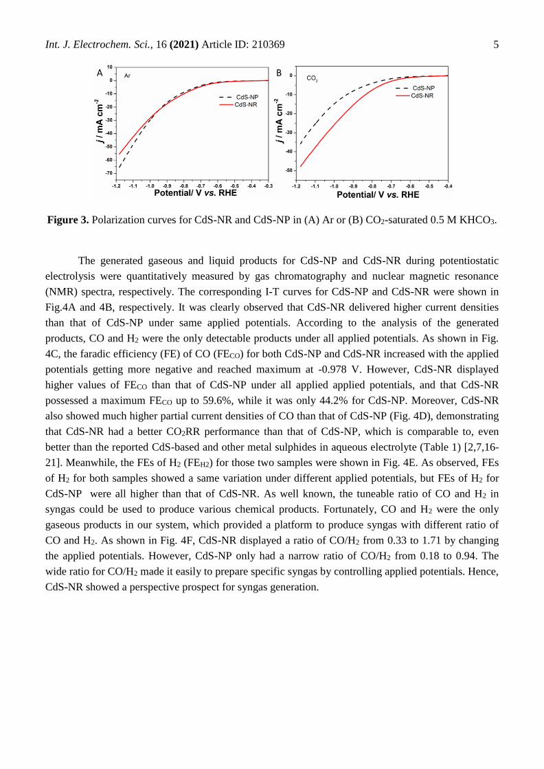
Polarization curves for CdS-NR and CdS-NR were recorded with a scan rate of 10 mV/s in Ar
or CO2-saturated 0.5 M KHCO3. As shown in Fig. 3A, CdS-NP and CdS-NR exhibited similar current
densities under Ar atmosphere under potentials positive than -0.95V. With applied potentials become
negative than -0.95 V, CdS-NP showed higher current densities. It was reported that hydrogen
evolution reaction (HER)-competing reaction of CO2RR mainly happened under Ar atmosphere [14].
Therefore, it was accepted that CdS-NP and CdS-NR displayed similar HER performances in Ar-
saturated electrolyte. However, in comparison with CdS-NP, CdS-NR showed much higher current
densities under CO2 atmosphere (Fig. 3B), demonstrating that CdS-NR possessed higher CO2RR
activity [15].
A B (002)
Int. J. Electrochem. Sci., 16 (2021) Article ID: 210369
5
Figure 3. Polarization curves for CdS-NR and CdS-NP in (A) Ar or (B) CO2-saturated 0.5 M KHCO3.
The generated gaseous and liquid products for CdS-NP and CdS-NR during potentiostatic
electrolysis were quantitatively measured by gas chromatography and nuclear magnetic resonance
(NMR) spectra, respectively. The corresponding I-T curves for CdS-NP and CdS-NR were shown in
Fig.4A and 4B, respectively. It was clearly observed that CdS-NR delivered higher current densities
than that of CdS-NP under same applied potentials. According to the analysis of the generated
products, CO and H2 were the only detectable products under all applied potentials. As shown in Fig.
4C, the faradic efficiency (FE) of CO (FECO) for both CdS-NP and CdS-NR increased with the applied
potentials getting more negative and reached maximum at -0.978 V. However, CdS-NR displayed
higher values of FECO than that of CdS-NP under all applied applied potentials, and that CdS-NR
possessed a maximum FECO up to 59.6%, while it was only 44.2% for CdS-NP. Moreover, CdS-NR
also showed much higher partial current densities of CO than that of CdS-NP (Fig. 4D), demonstrating
that CdS-NR had a better CO2RR performance than that of CdS-NP, which is comparable to, even
better than the reported CdS-based and other metal sulphides in aqueous electrolyte (Table 1) [2,7,16-
21]. Meanwhile, the FEs of H2 (FEH2) for those two samples were shown in Fig. 4E. As observed, FEs
of H2 for both samples showed a same variation under different applied potentials, but FEs of H2 for
CdS-NP were all higher than that of CdS-NR. As well known, the tuneable ratio of CO and H2 in
syngas could be used to produce various chemical products. Fortunately, CO and H2 were the only
gaseous products in our system, which provided a platform to produce syngas with different ratio of
CO and H2. As shown in Fig. 4F, CdS-NR displayed a ratio of CO/H2 from 0.33 to 1.71 by changing
the applied potentials. However, CdS-NP only had a narrow ratio of CO/H2 from 0.18 to 0.94. The
wide ratio for CO/H2 made it easily to prepare specific syngas by controlling applied potentials. Hence,
CdS-NR showed a perspective prospect for syngas generation.
A B

Int. J. Electrochem. Sci., 16 (2021) Article ID: 210369
6
Figure 4. Potential-dependant I-T curves for (A) CdS-NP and (B) CdS-NR with respect of time. (C)
Potential-dependent FE of CO CdS-NP and CdS-NR. (D) CO partial current densities for CdS-
NP and CdS-NR. (E) Potential-dependent FE of H2 for CdS-NP and CdS-NR. (F) Ratio of
FECO/FEH2 for CdS-NP and CdS-NR with respect of potentials.
Table 1. Comparison of the maximum FECO and the corresponding CO partial current densities for
CdS-NR in this work and other CdS-based and metal sulphides in aqueous electrolyte
Electrocatalyst Electrolyte FECO
(%)
jCO
(mA cm–2) Reference
CdS-NR 0.5 M KHCO3
59.6 14.8 This work
CdS-NP 44.2 7.8
CdS NNs 0.5 M KHCO3 91.1 8.2 [7]
CdS-CNTs 0.1 M KHCO3 92.0 10.5 [16]
P–Cd|S 0.25 M K2SO4 ~70 ~4 [17]
CdS nanorods 0.1 M KHCO3 81 21.9 [2]
CdS nanorods 0.5 M KHCO3 95 5.7 [18]
Cu2S 0.5 M KHCO3 15.8 31.6 [19]
h-CuS MCs 0.1 M KHCO3 32.7 - [20]
rGO-PEI-MoS2 0.5 M NaHCO3 85.1 0.3 [21]
B CA
D E F

Int. J. Electrochem. Sci., 16 (2021) Article ID: 210369
7
3.3 Mechanism for enhanced catalytic activity
Moreover, we further explored the origins of the better CO2RR performance of CdS-NR than
that of CdS-NP. Well known that the adsorption of CO2 was primary and important step for
electrocatalytic CO2RR. Therefore, CO2 adsorption measurement for CdS-NR and CdS-NP was firstly
conducted. As shown in Fig. 5A, at the given relative pressure (P/P0) (0.002~0.995), CdS-NR showed
a much higher CO2 adsorption ability than that of CdS-NP. A better adsorption of reactant always led
to a more excellent catalytic activity [22]. Furthermore, electron transfer was vital during
electrocatalytic CO2RR process. Therefore, electrochemical impedance spectroscopy (EIS) was taken
to analysis the charge-transfer behaviours. As shown in Fig. 5B, the smaller semicircle diameter of
CdS-NR reflected a smaller charge-transfer resistance and more favourable charge transfer kinetics,
which may due to the reason that the special rod-like micromorphology of CdS-NR could minimize the
electron transport distance [23]. Additionally, the electrochemically active surface areas (ECSA) of
CdS-NR and CdS-NP were obtained by calculating their double-layer capacitances (Cdl), since ECSAs
was in proportion to Cdl. Cdl was measured based on the CV curves at different scan rates under non-
faradic region (Fig. 6A-B). As shown in Fig. 6C, the measured Cdl of CdS-NR was 1.484 mF cm-2,
which was about 3.8 times larger than that of CdS-NP (0.395 mF cm-2), demonstrating that the CdS-
NR provided more accessible active sites, which benefited CO2RR [24]. Overall, in comparison with
traditional CdS nanoparticles, the unique nanorod-like structure endowed an enhanced electrocatalytic
CO2RR performance of CdS-NR.
Figure 5. (A) CO2 adsorption curves and (B) EIS for CdS-NR and CdS-NP.
Figure 6. CV curves at different scan rates for (A) CdS-NP and (B) CdS-NR. (C) Capacitive ΔC
against scan rates for CdS-NP and CdS-NR.
A B
A CB

Int. J. Electrochem. Sci., 16 (2021) Article ID: 210369
8
4. CONCLUSIONS
In summary, nanorod-like CdS-NR with a diameter of 10 nm was successfully synthesized via
a solvothermal method, which was used as electrocatalyst to produce syngas through electrocatalytic
CO2 reduction reaction. In comparison with commercial CdS nanoparticles, CdS-NR exhibited a much
better electrochemical performance toward syngas production in 0.5 M KHCO3. In detail, CdS-NR
possessed much higher values of FE and partial current densities for CO generation. More importantly,
syngas with various ratio of CO/H2 from 0.33 to 1.71 could be easily obtained for CdS-NR, while
CdS-NP only produces syngas with a narrow range from 0.18 to 0.94. The wide ratio for CO/H2 made
it desirable to prepare specific syngas by controlling applied potential. Systematic studies indicated
that the special nanorode-like structure of CdS-NR was beneficial to CO2 adsorption, charge transfer
and exposure of more active cites, which endowed it better electrochemical performance.
ACKNOWLEDGEMENTS
This work was supported by Science and Technology Planning Project of Longyan (2018LYF8009),
the National Natural Science Foundation of China (21802063), Natural Science Foundation of Fujian
Province (2019J05116), the Doctoral Scientific Research Foundation of Longyan University
(LB2018007), National Training Programs of Innovation and Entrepreneurship for Undergraduates
(201811312003 and 201911312002).
References
1. M. B. Ross, C. T. Dinh, Y. Li, D. Kim, P. De Luna, E. H. Sargent and P. Yang, J. Am. Chem.
Soc., 139 (2017) 9359.
2. R. He, A. Zhang, Y. Ding, T. Kong, Q. Xiao, H. Li, Y. Liu and J. Zeng, Adv. Mater., 30 (2018)
1705872.
3. S. Gao, Z. Sun, W. Liu, X. Jiao, X. Zu, Q. Hu, Y. Sun, T. Yao, W. Zhang, S. Wei and Y. Xie, Nat.
Commun., 8 (2017) 14503.
4. C. Cao and Z. Wen, J. CO2 Util., 22 (2017) 231.
5. Q. He, D. Liu, J. H. Lee, Y. Liu, Z. Xie, S. Hwang, S. Kattel, L. Song and J. G. Chen, Angew.
Chem. Int. Ed., 59 (2020) 3033
6. M. B. Ross, Y. Li, P. De Luna, D. Kim, E. H. Sargent and P. Yang, Joule, 3 (2019) 257.
7. F. Gao, S. Hu, X. Zhang, Y. Zheng, H. Wang, Z. Niu, P. Yang, R. Bao, T. Ma, Z. Dang, Y. Guan,
X. Zheng, X. Zheng, J. Zhu, M. Gao and S. Yu, Angew. Chem. Int. Ed., 132 (2020) 8784-8790.
8. S. N. A. Zakaria, N. Hollingsworth, H. U. Islam, A. Roffey, D. Santos-Carballal, A. Roldan, W.
Bras, G. Sankar, G. Hogarth, K. B. Holt and N. H. de Leeuw, ACS Appl. Mater. Inter., 10 (2018)
32078.
9. A. T. Landers, M. Fields, D. A. Torelli, J. Xiao, T. R. Hellstern, S. A. Francis, C. Tsai, J.
Kibsgaard, N. S. Lewis and K. Chan, ACS energy lett., 3 (2018) 1450.
10. D. Yang, Q. Zhu, X. Sun, C. Chen, W. Guo, G. Yang and B. Han, Angew. Chem. Int. Ed., 132
(2020) 2374.
11. C. K. Sheng, K. A. M. A. Amin, L. L. Hong, M. F. Hassan and M. Ismail, Int. J. Electrochem.
Sci., 12 (2017) 10023.
12. X. He and L. Gao, Matter. Lett., 63 (2009) 995.
13. J. xiong, Y. Liu, C. Cao, L. Shen, W. Wu, S. Liang, R. Liang and L. Wu, J. Mater. Chem. A, 3
(2015) 6935.
14. C. Cao, D. D. Ma, J. F. Gu, X. Xie, G. Zeng, X. Li, S. G. Han, Q. L. Zhu, X. T. Wu and Q. Xu,

Int. J. Electrochem. Sci., 16 (2021) Article ID: 210369
9
Angew. Chem. Int. Ed., 59 (2020) 15014.
15. B. Jiang, X. G. Zhang, K. Jiang, D. Y. Wu and W. B. Cai, J. Am. Chem. Soc., 140 (2018) 2880.
16. B. Qin, Y. Li, H. Wang, G. Yang, Y. Cao, H. Yu, Q. Zhang, H. Liang and F. Peng, Nano Energy,
60 (2019) 43.
17. Y. Wu, P. Zhai, S. Cao, Z. Li, B. Zhang, Y. Zhang, X. Nie, L. Sun and J. Hou, Adv. Energy.
Mater., 10 (2020) 2002499.
18. Y. Li, L. Cheng, P. Liu, L. Zhang, M. Zu, C. Wang, Y. Jin, X. Cao, H. Yang and C. Li,
ChemSusChem, 11 (2018) 1421.
19. T. Zhuang, Z. Liang, A. Seifitokaldani, Y. Li, P. D. Luna, T. Burdyny, F. Che, F. Meng, Y. Min,
R. Quintero-Bermudez, C. T. Dinh, Y. Pang, M. Zhong, B. Zhang, J. Li, P. Chen, X. Zheng, H.
Liang, W. Ge, B. Ye, D. Sinton, S. Yu and E. H. Sargent, Nature Catal., 1 (2018) 421.
20. P. Shao, S. Ci, L. Yi, P. Cai, P. Huang, C. Cao and Z. Wen, ChemEletroChem, 4 (2017) 2593.
21. F. Li, S. Zhao, L. Chen, A. Khan, D. R. Macfarlane and J. Zhang, Energy Environ. Sci., 9 (2016)
216.
22. S. Gao, Y. Lin, X. Jiao, Y. Sun, Q. Luo, W. Zhang, D. Li, J. Yang and Y. Xie, Nature, 529 (2016)
68.
23. J. Xie, J. Zhang, S. Li, F. Grote, X. Zhang, H. Zhang, R. Wang, Y. Lei, B. Pan and Y. Xie, J. Am.
Chem. Soc., 135 (2013) 17881.
24. M. A. Lukowski, A. S. Daniel, C. R. English, F. Meng, A. Forticaux, R.J. Hamers and S. Jin,
Energy Environ. Sci., 7 (2014) 2608.
© 2021 The Authors. Published by ESG (www.electrochemsci.org). This article is an open access
article distributed under the terms and conditions of the Creative Commons Attribution license
(http://creativecommons.org/licenses/by/4.0/).