surgical technique - synthes.vo.llnwd.netsynthes.vo.llnwd.net/o16/llnwmb8/int mobile/synthes...
TRANSCRIPT
Surgical Technique
Small External Fixator

Image intensifier control
This description alone does not provide sufficient background for direct use of DePuy Synthes products. Instruction by a surgeon experienced in handling these products is highly recommended.
Processing, Reprocessing, Care and MaintenanceFor general guidelines, function control and dismantling of multi-part instruments, as well as processing guidelines for implants, please contact your local sales representative or refer to:http://emea.depuysynthes.com/hcp/reprocessing-care-maintenanceFor general information about reprocessing, care and maintenance of DePuy Synthes reusable devices, instrument trays and cases, as well as processing of DePuy Synthes non-sterile implants, please consult the Important Information leaflet (SE_023827) or refer to: http://emea.depuysynthes.com/hcp/reprocessing-care-maintenance

Small External Fixator Surgical Technique DePuy Synthes 1
Table of Contents
Introduction Small External Fixator 2
System Overview 3
Indications, Contraindications and Warning 4
MRI Information 5
Surgical Technique Bridging Surgical Technique 6
Non-bridging Surgical Technique 12• Variant A: Modular Technique with Schanz Screws 13• Variant B: with Kirschner Wires 22
Product Information Product Information 26

2 DePuy Synthes Surgical Technique Small External Fixator
Simple handling• Clamps with clip-on self-holding mechanism• Color-coded for identification• MR conditional
Flexible system• The system can be configured to the user’s require-
ments and the specific anatomic situation• Free pin placement• Compatibility with other DePuy Synthes external
fixator systems • Suitable for bridging and non-bridging surgical
techniques
StabilityThe material properties of the TAV clamps, the carbon fibre rods, and pure titanium pins provide stability, and are light weight.
A clamp for all connection options• Grips 1.8–4.0 mm• Two nuts for independent fixation of the implant
and/or the carbon fibre rod
Combination clamp• Grips 2.5 – 4.0 mm • A nut for the fixation of the implant and/or carbon fibre
rod
Curved carbon fibre, 4.0 mm• Ideal for non-bridging fixation of
distal radial fractures
Straight carbon fibre rod, 4.0 mm• For modular frame configurations
SELDRILLTM Schanz screws• Reinforced bone anchoring due to radial preloading• Available in pure titanium and stainless steel• Compatible with the small external fixator 2.5/4.0,
3.0/4.0 and 4.0 mm
Kirschner wires• Material: titanium alloy and stainless steel• Recommended diameter for the system 1.8, 2.0 and 2.5 mm
Small External Fixator

Small External Fixator Surgical Technique DePuy Synthes 3
System Overview
Overview of available Fixator systems
Rod FixatorsExternal Fixation Family (clip-on)
Supplements to the External Fixation Family
Monolateral SystemsMEFiSTO Systems
Large rod 11 mm
Large External Fixator Hybrid Ring Fixator Carbon fibre tube
Medium rod 8 mm
Medium External Fixator External Distal Radius Fixator (DRF)
Small rod 4 mm
Small External Fixator
Mini rod 3 mm
External Mini-Fixator
* MEFiSTO central body, MEFiSTO angulator, and MEFiSTO segment transport are also available
MEFiSTO Central Body MEFiSTO Angulator MEFiSTO Segment Transport
4 DePuy Synthes Surgical Technique Small External Fixator
Indications, Contraindications and Warning
Indications
Unstable distal radius fractures• Intra-articular • Extra-articular• Preliminary fixation before open reduction and internal
fixation • Fracture with open and closed soft tissue injury• Multiple trauma (in terms of “damage controlled
surgery” – injury-adapted care)
Other indications
Injuries, fractures, dislocations, burns• Carpal region• Wrist• Forearm• Ankle (possibly in combination with
a medium or large fixator)
Fractures in combination with • Extensive soft tissue injuries • Bone loss• Vascular and/or neural involvement
Fracture dislocation• Carpal bones
Failed closed reduction with casting resulting in secondary dislocation • Radial shortening• Angulation
ContraindicationsNo specific contraindications
Warning: The treating physician should make patientspecificclinicaljudgmentanddecisiontouse External Fixation System in patients with the following conditions:• Patients who for social and physical reasons are notsuitableforanexternalfixator.
• Agitation• Patients in whom screws cannot be inserted due
to a bone or soft tissue disease.

Small External Fixator Surgical Technique DePuy Synthes 5
MRI Information
Small External Fixator devices used in a typical construct include clamps, rods and various attachments. A patient with a DePuy Synthes Small External Fixator frame may be scanned safely after placement of the frame under the following conditions:
• Static magnetic field of 1.5 Tesla or 3.0 Tesla when the fixator frame is positioned outside the MRI Bore at Normal Operator or in First Level Control Mode
• Highest spatial gradient magnetic field of 720 Gauss/cm or less
• Maximum MR system reported whole body averaged specific absorption rate (SAR) of 2 W/kg for the Normal Operating Mode and 4 W/kg for the First Level Con-trolled Mode for 15 minutes of scanning
• Use only whole body RF transmit coil, no other trans-mit coils are allowed, local receive only coils are allowed
• Specialty coils, such as knee or head coils, should not be used as they have not been evaluated for RF heat-ing and may result in higher localized heating
NoteIn nonclinical testing, the Small External Fixator frame was tested in several different configurations. This test-ing was conducted with the construct position 7 cm from within the outside edge of the MRI bore.The results showed a maximum observed heating for the wrist fixator frame of less than 4 °C for 1.5 T and less than 2 °C for 3.0 T with a machine reported whole body averaged SAR of 2 W/kg.
PrecautionsPatients may be safely scanned in the MRI chamber un-der the above conditions. Under such conditions, the maximum expected temperature rise is less than 6 °C. Because higher in vivo heating cannot be excluded, close patient monitoring and communication with the patient during the scan are required. Immediately abort the scan if the patient reports burning sensation or pain. To mini-mize heating, the scan time should be as short as possi-ble, the SAR as low as possible and the device should be as far as possible from the edge of the bore. Tempera-ture rise values obtained were based upon a scan time of 15 minutes.
The above field conditions should be compared with those of the user’s MR system in order to determine if the item can safely be brought into the user’s MR envi-ronment.
If placed in the bore of the MR scanner during scanning, DePuy Synthes Small External Fixator devices may have the potential to cause artifact in the diagnostic imaging.
Warnings• Only use frame components stated in the surgical tech-
nique of the Small External Fixator System• Potential complications of putting a part in the MR field
are:– Torsional forces can cause the device to twist in MR
field– Displacement forces can pull the device into the MR
field– Induced currents can cause peripheral nerve stimu-
lation– Radio Frequency (RF) induced currents can cause
heating of the device that is implanted in the patient• Do not place any radio frequency (RF) transmit coils
over the Small External Fixator frame
Artifact InformationMR image quality may be compromised if the area of in-terest is in the same area or relatively close to the posi-tion of the DePuy Synthes Small External Fixator frame. It may be necessary to optimize MR imaging parameters in order to compensate for the presence of the fixator frame.
Representative devices used to assemble a typical Small External Fixator frame have been evaluated in the MRI chamber and worst-case artifact information is provided below. Overall, artifacts created by DePuy Synthes Small External Fixator System devices may present issues if the MR imaging area of interest is in or near the area where the fixator frame is located.• For FFE sequence: scan duration 3 minutes, TR 100 ms,
TE 15 ms, flip angle 15° and SE sequence: scan dura-tion 4 minutes, TR 500 ms, TE 20 ms, flip angle 70° radio echo sequence, worst-case artifact will extend approximately 10 cm from the device

6 DePuy Synthes Surgical Technique Small External Fixator
Bridging Surgical Technique
The assembly of the small external fixator is described here using the 3-rod modular technique on the distal radius as the example.
At the start, perform an initial reduction on the hand with the fractured radius by gentle ligamentotaxis to minimize soft tissue injuries through internal pressure.
1. Angle for screw insertion
Implant the Schanz screws into the second metacarpal.
Notes: • For a better purchase, it is recommended to insert
these at a slight angle. An angle of 40° to 60° be-tween the proximal and distal pin has proven to be best.
• For a detailed handling description of the Schanz Screws, refer to the Surgical Technique Schanz Screws and Steinmann Pins (DSEM/TRM/0516/0677).
2. Position of the screws
Pay attention to the extensor tendon and the radiodorsal neuro vascular bundle on the extensor and radiodorsal side. If the screws are placed too far laterally, they will impede the function of the thumb. For this reason, an angle between 40° and 60° with respect to the horizon-tal has proven best when viewed from the orthograde position.

Small External Fixator Surgical Technique DePuy Synthes 7
3. Insertion of screws
The Schanz screws can be placed first in the second metacarpal or radius. Insert the drill sleeve in the radius and particularly in the second metacarpal, while protect-ing and pushing aside the extensor tendon. Maintain a secure bone contact when implanting the Schanz screws with the drill sleeve.
Precautions:• Instruments and screws may have sharp edges
or moving joints that may pinch or tear user’s glove or skin.
• Handle devices with care and dispose worn bone cutting instruments in an approved sharps con-tainer.
4. Screw diameters
Insert two Schanz screws each into the second metacar-pal and the radius. Depending on the size of the skele-ton, select Schanz screws with a diameter between 2.5 mm and 4.0 mm for the second metacarpal and Schanz screws with a diameter of 4.0 mm for the radius.
It is recommended for the shaft that cooling be provided for the drilling or insertion of the SELDRILL Schanz screw. To accomplish this, the connector on the drill sleeve can be connected to a tube and a syringe.
Precautions: • The SELDRILL Schanz screw has been developed
to minimise heat development. Nevertheless, slow insertion and additional cooling (for example with a Ringer solution) are recommended.
• The tip of the SELDRILL Schanz screw should be embedded in the far cortex to effectively resist cantileverforcesandtoprovidesufficientstability.
Note: Less experienced users are advised to use a hand drill when placing the SELDRILL Schanz screw in the far cortex.

8 DePuy Synthes Surgical Technique Small External Fixator
Bridging Surgical Technique
5. Construction of partial frames
Connect the pairs of Schanz screws in the radius and the second metacarpal using short rods. Firmly tighten the clamps of these partial frames.
Note: Select the rod length so that the ends near the fracture do not interfere with each other during the laterreductionbutthereissufficientroomattheend of the rods to attach the middle modular rod to the partial frames with two additional clamps (modular clamps).
This is achieved, for example, by placing the rod in the second metacarpal on the ulnar side and in the radius on the radial side (or vice versa).

Small External Fixator Surgical Technique DePuy Synthes 9
Alternative with reduction rods
6. Partial frames as reduction handles
Use the partial frames as handles for every main bone to be reduced. The fracture can be reduced in all six degrees of freedom (longitudinal-ligamentotaxis, transla-tion, and rotation). This technique protects soft tissues from pressure and compression.
11 DePuy Synthes Surgical Technique Small External Fixator
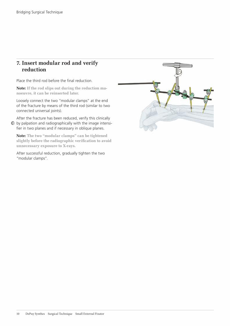
7. Insert modular rod and verify reduction
Place the third rod before the final reduction.
Note: If the rod slips out during the reduction ma-noeuvre, it can be reinserted later.
Loosely connect the two “modular clamps” at the end of the fracture by means of the third rod (similar to two connected universal joints).
After the fracture has been reduced, verify this clinically by palpation and radiographically with the image intensi-fier in two planes and if necessary in oblique planes.
Note: The two “modular clamps” can be tightened slightlybeforetheradiographicverificationtoavoidunnecessary exposure to X-rays.
After successful reduction, gradually tighten the two “modular clamps”.
Bridging Surgical Technique

Small External Fixator Surgical Technique DePuy Synthes 11
8. Benefits of the 3-rod modular technique
The 3-rod modular technique allows rapid and secure reduction and retention with protection of soft tissue.
A secondary correction or adjustment can also be made easily at any time by opening the two “modular clamps”.
9. Additional stabilisation
The construct can be stabilised as needed by using a “neutralization rod“. Depending on the position, it is sufficient to grasp one end of the screw from the distal and proximal group.
Finally, verify again whether all clamps have been tight-ened well.

12 DePuy Synthes Surgical Technique Small External Fixator
Non-bridging Surgical Technique
Recommended zones in the wrists
Schanz screws or Kirschner wires are to be used in the forearm and wrist and finger region in the recom-mended zones not involving tendons, nerves, and vessels.
The following apply to the fragment near the wrist, par-ticularly if a non-bridging construct technique is used for distal radius fractures:There are narrow recommended zones between the ex-tensor compartments dorsally and dorsoradially. Placing the fixator in these critical zones requires appropriate background knowledge of anatomy. Before the Schanz screws and/or Kirschner wire can be inserted, the ten-don compartments are palpated, except when swelling makes this impossible.
Make a small longitudinal incision and palpate the chan-nel through this incision with a suitable instrument (small curved clamp, small curved, unopened scissors, or the like) until there is secure contact with the bone surface. Cautiously advance the multidrill sleeve with the protec-tive trocar into this channel, so that this sleeve assembly is securely in contact with bone.
With slight spreading and pendular motions, place both the separator and the drill sleeve assembly securely be-tween the tendon compartments. To avoid any uncer-tainty, the tactile contact must provide definite feedback or the bone surface must be visible.
Insert the Schanz screw with the drill sleeve assembly being in constant contact with the bone.
Note: For a detailed handling description of the Schanz screws, refer to the Surgical Technique Schanz Screws and Steinmann Pins (DSEM/TRM/0516/0677).
Recommended zone
Recommended zone
Recommended zone

Small External Fixator Surgical Technique DePuy Synthes 13
Variant A: Modular Technique with Schanz ScrewsPrecaution: Select the appropriate Schanz screw for the patient’s bony anatomy.
Insert 2 Schanz screws each into the radial shaft and the distal radius fragment. Connect the main fragments with a 4 mm carbon fibre rod and tighten the clamps firmly.
A curved carbon fibre rod can also be used in the distal fragment. Each main fragment thus has its individual frame and can be manipulated and repositioned using its frame.
As a rule, use the modular intermediate rod. This rod can also be inserted for the first time after the reduc-tion. This intermediate rod connects the distal and proxi-mal frames at any desired place.
The reduction can be made easier by long rods (with 1 or 2 clamps), which are attached temporarily during the surgery. The long rods point away from the fracture so that the re duction is easier and more differentiated and contact with the X-ray beam of the image intensifier can be avoided.
After the reduction the clamps lock this intermediate rod.
Depending on the situation, this modular frame can be stabilised still further with a neutralization rod.
1. First positioning
The positioning and covering follow general and local guidelines. Initial reduction in a very severe dislocation can be performed during the preparation for surgery.

14 DePuy Synthes Surgical Technique Small External Fixator
2. Inserting the screws in the radial shaft
Insert two Schanz screws in the radial shaft from the dorso radial direction. Make sufficiently large stab inci-sions, spread the tissue to the bone, and push aside muscles, tendons, vessels, and nerves by feel and to some extent by sight.
Always insert the 3-part drill sleeve assembly until there is secure contact with the bone. Then implant the Schanz screws.
Note: When using SELDRILL Schanz screws, merely drillinthescrews.Withconventionalscrews,firstpredrill holes and then insert the screws. An angle of 10° to a maximum of 45° (in the radius) is recom-mendedifthebonesarethin.Thisisabenefitbutnot essential with weak bones. Select the pitch of thescrewstofittheactualconditions.
It is recommended for the shaft that cooling be provided for the drilling or insertion of the SELDRILL Schanz screw. To accomplish this, the connector on the drill sleeve can be connected to a tube and a syringe.
Precaution: Only when bones are osteoporotic does the SELDRILL Schanz screw have to be screwed a bit further into the distant cortical bone, and it may even slightly penetrate through it since this can in-crease anchoring stability.
Note: A SELDRILL Schanz screw can be turned back without loosening as the thread is not conical.
Non-bridging Surgical Technique – Variant A

Small External Fixator Surgical Technique DePuy Synthes 15
3. Connecting the screws in the radial shaft
Connect the screws with a straight 4 mm carbon fibre rod. The position of the distal frame is readily evident.
The intermediate rod can also be selected “diagonally” through the Schanz screws, sometimes on the radial and sometimes on the ulnar side. A certain pitch results and the end collides less with the distal frame. The projection relative to the fracture should be 1 to 2 cm, so that there is room for a clamp.
Tighten all nuts firmly.

16 DePuy Synthes Surgical Technique Small External Fixator
4. Inserting screws in the distal fragment
Insert two Schanz screws in the recommended zones be-tween the tendons and the vascular compartments of the distal fragment. Make adequate but not too large stab incisions at the correct place.
Spread and push aside the soft tissues, tendons, nerves, and vessels until there is secure contact with the bone. Position the drill sleeve assembly (make sure that there is constant contact with the bone) and insert the Schanz screws.
Precaution: The tip of the Self-tapping Schanz screw should be embedded in the far cortex to effectively resistcantileverforcesandtoprovidesufficient stability.
Note: Use self-drilling SELDRILL Schanz screws without conventional screws with predrilling. Bear in mind the recommended zones (see anatomic diagram on page 12).
Schanz screws can be used with the modular technique in any manner.
There are two variants of the surgical technique; these can be varied at any time according to requirements.
4a.Schanz screws at a 60 to 90° to each other, one from the radial and the other from the dorsal direction
Non-bridging Surgical Technique – Variant A

Small External Fixator Surgical Technique DePuy Synthes 17
4b.Both Schanz screws from the radial direction
The further surgical technique is identical for a and b; this is an outstanding feature of the modular technique.
5. Connecting screws in the distal fragment
Connect the two Schanz screws of the distal fragment. Use a straight 4 mm carbon fibre rod, a 4 mm stainless steel rod, or a 4 mm curved carbon fibre rod here. The last rod enables to connect the 2 Schanz screws elegantly around the soft tissue.
Note: The side on which the rod is placed is not import-ant for the surgical technique. Care must be taken that the frame construct of the distal fragment and the frame of the shaft fragment do not interfere with each other during the reduction manoeuvre.
Tighten the nuts of the distal frame firmly. The nuts of both partial frames must be tightened well.

18 DePuy Synthes Surgical Technique Small External Fixator
5b.Both Schanz screws radial
The remaining surgical technique applies to both 5a and 5b. However, the technique is shown in the drawings only for 5a.
5a.Schanz screws at a 60 to 90° to each other, one radial and the other dorsal
Position of the Schanz screws in the distal fragment:
Non-bridging Surgical Technique – Variant A
Small External Fixator Surgical Technique DePuy Synthes 19
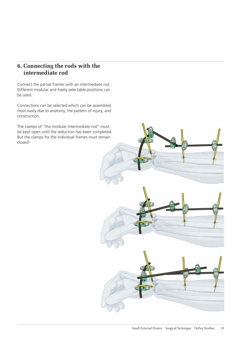
6. Connecting the rods with the intermediate rod
Connect the partial frames with an intermediate rod. Different modular and freely selectable positions can be used.
Connections can be selected which can be assembled most easily due to anatomy, the pattern of injury, and construction.
The clamps of “the modular intermediate rod” must be kept open until the reduction has been completed. But the clamps for the individual frames must remain closed!

21 DePuy Synthes Surgical Technique Small External Fixator
7. Reduction
The partial frames can be grasped and used to reposition the bone. The reduction may not be performed over al-ready injured soft tissue.
This step can be supplemented with “accessory reduc-tion rods”: 4 mm rods (200 mm), which point away from the fracture, are used on the partial frames with 1 or 2 clamps. It is beneficial if these rods are parallel to the radial shaft and parallel to the metacarpal. The reduction can be performed in a differentiated and tissue-sparing manner with use of these rods, put in place temporarily during surgery. Hands must be outside the central beam of the X-ray image intensifier during intraoperative X-ray image intensifier verification!
Reduction can be verified clinically or if necessary radiographically (X-ray image intensifier).
Non-bridging Surgical Technique – Variant A

Small External Fixator Surgical Technique DePuy Synthes 21
9. Attaching the neutralization rod
It can be attached anywhere in the partial frame. One clamp per partial frame is sufficient. The use of an additional clamp depends on various factors: • the patient’s weight • fracture configuration / instability• distance to the fragment • the free lengths of the Schanz screws • the length of the modular intermediate rods
The more angled the rod and the greater the distances, the weaker and more elastic the construct. A neutraliza-tion rod can be attached here for better stabilisation.
Finally, verify again whether all clamps have been tight-ened.
Precautions:• Implant sites should be meticulously cared to
avoid pin-tract infection. Schanz screws may be surrounded with antiseptic coated foam sponges in an effort to avoid infection. An implant-site care procedure should be reviewed with the patient.
• To minimize the risk of pin track infection, the following points should be observed:a. Placement of Schanz screws taking anatomy
into consideration (ligaments, nerves, arteries).b. Slow insertion and/or cooling, particularly in
dense, hard bone to avoid heat necrosis.c. Release of skin tension at soft tissue entry point
of implant.
8. Tightening of the clamps of the intermediate rod
Tighten the two clamps, which connect the modular rod between the partial frames. Take care that the tighten-ing proceeds sequentially to allow the shaft to make contact with the cogs.
Verify the achieved reduction manoeuvre clinically and radiographically. If it is not satisfactory, steps 7 and 8 can be repeated as often as desired.

22 DePuy Synthes Surgical Technique Small External Fixator
Before stabilising with Kirschner wires, reposition using the bridging technique. If a sufficient reduction can be achieved with gentle pulling, the repositioning can be omitted. In this variant, the frame for stabilising the fracture is configured according to the bridging surgical technique with the already described modular technique.
The neutralization rod in step 9 usually does not need to be attached.
2. Inserting the Kirschner wires
Insert 2, 3, or 4 Kirschner wires and stabilise the fracture.Bridge a intraarticular fracture with 1 Kirschner wire. Place the other two Kirschner wires from distal area into the shaft region. Connect all Kirschner wires with a curved carbon fibre rod. The ends of the Kirschner wires can be bent so that they point in the same direction.
1. Bridging modular technique for reduction
Perform steps 1 to 8 of the surgical technique of the bridging variant without prior reduction and temporary stabilisation using the 3-rod modular technique.
Non-bridging Surgical Technique
Variant B: with Kirschner wires

Small External Fixator Surgical Technique DePuy Synthes 23
3. Removing part of the construct
Loosen the bridging and remove the front part of the construct. The construct now no longer bridges. The Kirschner wires used in the distal fragment remain con-nected to the frame of the shaft fragment.
If the fracture is very unstable, the bridging construct can also be removed later.
Note: For instructional reasons, a diagram is not provided for this procedure.
4. Connecting the Kirschner wires
Connect all Kirschner wires using a rod.
Only minor fine reductions are possible with Kirschner wires, which bridge the main fracture and open into the shaft. These can be performed using the modular technique.

24 DePuy Synthes Surgical Technique Small External Fixator
5. Connecting the partial frames
After making the connection between the Kirschner wires, tighten all clamps.
5a.Connect the partial frames (distal radial fragment and radial shaft). If a fine reduction is no longer necessary, the distal partial frame can be connected with a 4 mm rod and Schanz screws.
5b.If a fine reduction or later reduction and correction are anticipated, the use of a modular intermediate rod be-tween the partial frames at the distal fragment and shaft is recommended in this case as well.
Non-bridging Surgical Technique – Variant B

Small External Fixator Surgical Technique DePuy Synthes 25
6. Attaching the neutralization rod
Depending on need and actual conditions, a neutraliza-tion rod can be attached between any places on any partial frame.
This gives the system additional stability.
Precautions:• Implant sites should be meticulously cared to
avoid pin-tract infection. Schanz screws may be surrounded with antiseptic coated foam sponges in an effort to avoid infection. An implant-site care procedure should be reviewed with the patient.
• To minimize the risk of pin track infection, the following points should be observed:a. Placement of Schanz screws taking anatomy into
consideration (ligaments, nerves, arteries).b. Slow insertion and/or cooling, particularly in
dense, hard bone to avoid heat necrosis.c. Release of skin tension at soft tissue entry point
of implant.

26 DePuy Synthes Surgical Technique Small External Fixator
Product Information
Set Units
186.430 Small External Fixator in Vario Case
Case
686.430 Vario Case for Small External Fixator, without Lid, without Contents 1
Instruments
395.360 Socket Wrench, 7.0 mm 1
395.350 Combination Wrench 7.0 mm 1
324.300 Drill Sleeve Assembly, complete, Stainless Steel 1
Fixation Components
395.578 Clamp, clip-on, self-holding, Titanium Alloy (TAV) 12
390.041 Combination Clamp, clip-on, self-holding, Titanium Alloy (TAV) 4
395.600 Connecting Rod 4.0 mm, length 60 mm, Carbon Fibre 4
395.610 Connecting Rod 4.0 mm, length 80 mm, Carbon Fibre 4
395.620 Connecting Rod 4.0 mm, length 100 mm, Carbon Fibre 4
395.630 Connecting Rod 4.0 mm, length 120 mm, Carbon Fibre 4
395.640 Connecting Rod 4.0 mm, length 140 mm, Carbon Fibre 2
395.650 Connecting Rod 4.0 mm, length 160 mm, Carbon Fibre 2
395.660 Connecting Rod 4.0 mm, length 180 mm, Carbon Fibre 2
395.670 Connecting Rod 4.0 mm, length 200 mm, Carbon Fibre 2
324.304 Carbon Fibre Rod 4.0 mm, curved, radius 60 mm 2
Implants Units
494.769 SELDRILL Schanz Screw 4.0/2.5 mm, length 80/20 mm, Pure Titanium 6
494.771 SELDRILL Schanz Screw 4.0/3.0 mm, length 80/20 mm, Pure Titanium 6
494.775 SELDRILL Schanz Screw 4.0 mm, length 80/20 mm, Pure Titanium 6
492.170 Kirschner Wire 1.8 mm with trocar tip, length 150 mm, Titanium Alloy (TAV) 10
492.200 Kirschner Wire 2.0 mm with trocar tip, length 150 mm, Titanium Alloy (TAV) 10
Optional
324.305 Torque Wrench, 4.0 Nm, Stainless Steel
395.510 Compressor, open
324.306 Allen Nut, width across 7.0 mm, for No. 324.305, Stainless Steel
Note: For a detailed product information of the Schanz screw, refer to the Surgical Technique Schanz Screws and Steinmann Pins (DSEM/TRM/0516/0677)


0123
Not all products are currently available in all markets.
This publication is not intended for distribution in the USA.
All surgical techniques are available as PDF files at www.depuysynthes.com/ifu
Synthes GmbHEimattstrasse 34436 OberdorfSwitzerlandTel: +41 61 965 61 11www.jnjmedicaldevices.com ©
DeP
uy S
ynth
es T
raum
a, a
div
isio
n of
Syn
thes
Gm
bH. 2
020.
A
ll rig
hts
rese
rved
. D
SE
M/T
RM
/041
6/06
53
SE
_808
404
AA
05
/20