supplement to chbdc s6-14 12 - british columbia
TRANSCRIPT

Supplement to CHBDC S6-14
Section 12 Barriers and highway accessory supports
October 28 2016 -1- BC MoTI
12.4 BARRIERS ..................................................................................................................... 2 12.4.1 General .................................................................................................................. 2 12.4.2 Barrier joints .......................................................................................................... 3 12.4.3 Traffic barriers ....................................................................................................... 3
12.4.3.2 Test level ........................................................................................................... 3 12.4.3.2.1 General....................................................................................................... 3 12.4.3.2.5 Test level for barriers on low volume roads .............................................. 8
12.4.3.3 Geometry and end treatment details ................................................................. 8 12.4.3.5 Anchorages ....................................................................................................... 8
12.4.4 Pedestrian barriers ................................................................................................ 9 12.4.4.1 General .............................................................................................................. 9 12.4.4.2 Geometry ........................................................................................................... 9 Figure 12.2 – Geometry of side-mounted pedestrian and bicycle barriers ........................ 9
12.4.5 Bicycle barriers ...................................................................................................... 9 12.4.5.1 General ......................................................................................................... 9 12.4.5.2 Geometry ........................................................................................................... 9
12.4.6 Combination barriers ........................................................................................... 10 12.4.6.1.a Configuration of combination barriers ......................................................... 10 12.4.6.1.b Pedestrian combination barriers ................................................................. 10 12.4.6.1.c Bicycle combination barriers ....................................................................... 12 12.4.6.2 Geometry ......................................................................................................... 13

Supplement to CHBDC S6-14
Section 12 Barriers and highway accessory supports
October 28 2016 -2- BC MoTI
12.4 Barriers
12.4.1 General
Commentary: The CHBDC provides detailed coverage of the “warrants” for a bridge traffic or combination barrier. Through the use of site-specific factors (i.e.: traffic volume, bridge geometry, etc.), an appropriate barrier performance, or “test level” can be analytically determined using the CHBDC methodology. In general, the Ministry’s Supplement to the CHBDC requires no changes to this approach.
However, the CHBDC provides only limited guidance on the design of a bridge traffic or combination barrier. This guidance includes a minimum barrier height requirement and specifies that barrier adequacy shall be determined from crash tests. Specific barrier design requirements are left to individual jurisdictions to establish. Hence, the content of this chapter of the Ministry’s Supplement focuses on bridge barrier design and detailing.
The CHBDC identifies additional factors to be considered in the appraisal of a barrier. These factors are further considered and supplemented as follows:
Barrier Attachments: Attachments on top of barriers (i.e.: poles, railings) can present a snag hazard to an impacting vehicle. This snag can adversely affect the impacting vehicle’s trajectory, as well as creating a potential compartment intrusion and/or debris hazard. Two strategies to mitigate this hazard are to offset the attachment behind the barrier face, outside the barrier’s “Zone of Intrusion” (ZOI), or to increase the barrier height to reduce the impacting vehicle’s “ride-up”, effectively reducing the barrier’s ZOI.
Where possible, all barrier attachments shall be removed from the barrier’s ZOI. Otherwise, the snag risks can still be minimized by increasing the setback as much as possible and grouping several accessories on a single attachment.
While still a relatively new topic, further information and delineation of the ZOI limits for different test levels can be found here: Zone of Intrusion and Concrete Barrier Countermeasures (2010, Stephen Hobbs, Annual Conference of the Transportation Association of Canada)
Deck Drainage: To facilitate deck drainage, some recent projects have incorporated a large drain opening (scuppers) in the barrier face to channel water off of the deck and into an externally-mounted discharge pipe. Note that a large drainage opening is already approved for use in roadside applications, as per the Ministry’s Precast Concrete Drainage Barrier (SP941-01.02.05). Such large openings can present a hazard due to snagging of a vehicle’s wheel during impact. The use of a large drainage opening in a bridge traffic or combination barrier shall be avoided where possible. Use of scuppers requires the consent of the Ministry. (See Supplement Section 1.8.2.3.3.)

Supplement to CHBDC S6-14
Section 12 Barriers and highway accessory supports
October 28 2016 -3- BC MoTI
Electrical Conduits and Junction Boxes: Concrete bridge and combination barriers can serve as a convenient location for running electrical conduit over the bridge length. The size and number of conduits should be limited such that their presence does not have an adverse effect on the crash performance of the barrier. Criteria are provided in Supplement Section 1.7.3.2. The conduit(s) should be located at the base of the barrier, within the rebar cage. The junction boxes to service the conduit should, in most cases, be located in the rear (non-impact) face of the barrier.
Further Barrier Reference: For expanded detail on all bridge barrier topics, a recent and relevant Canadian reference document is the Guide to Bridge Traffic and Combination Barriers (2010, Transportation Association of Canada).
12.4.2 Barrier joints
Barrier joints with openings greater than 100 mm shall be protected by sliding steel plates to prevent catchment of vehicles. All steelwork shall be protected from corrosion with hot-dipped galvanizing in accordance with ASTM A 123M.
Commentary: Barrier joints and the ends of a barrier present a load path discontinuity resulting in a shortened zone for impact load dispersal to the bridge deck. Supplemental barrier anchorage and deck reinforcing is sometimes required in these end zones.
12.4.3 Traffic barriers
12.4.3.2 Test level
12.4.3.2.1 General
The following bridge traffic barrier “reference concepts” have been accepted by the Ministry for use on highway bridges in B.C. Other bridge traffic barrier concepts may be considered but require prior Approval.
All bridge barrier design shall meet the CHBDC requirements for crash testing. Each of the listed “reference concepts” is known to have met the CHBDC requirements for crash testing. Jurisdictional usage for each listed “reference concept” is included. The Design Engineer shall confirm the applicability of the of the “reference concept” with respect to crash testing, usage and detailing.

Supplement to CHBDC S6-14
Section 12 Barriers and highway accessory supports
October 28 2016 -4- BC MoTI
TL-1 W-Beam Commentary: Details based on USDA Forest Service W-Beam Bridge Rail.
TL-2 Thrie Beam (Side Mounted) Commentary: Side mounted details based on Oregon Standard Drawing BR233.
TL-2 Thrie Beam (Top Mounted) Commentary: Top mounted details based on Alberta Standard Drawing S-1652-00.

Supplement to CHBDC S6-14
Section 12 Barriers and highway accessory supports
October 28 2016 -5- BC MoTI
TL-2 Two Rails (Side Mounted) Commentary: Side mounted details based on California Type 115 Bridge Rail.
TL-2 Two Rails (Top Mounted) Commentary: Top mounted system based on California Type 115 Bridge Rail, modified for top mounted anchorage. Modified anchorage to be designed in accordance with Clause 12.4.3.5 in the CHBDC.
TL-4 “F” Shape (Cast-in-Place Concrete) See the Ministry’s Standard Bridge Parapet (2874-1) for detailing. Commentary: Similar systems are used widely in jurisdictions across North America.
Supplement to CHBDC S6-14
Section 12 Barriers and highway accessory supports
October 28 2016 -6- BC MoTI
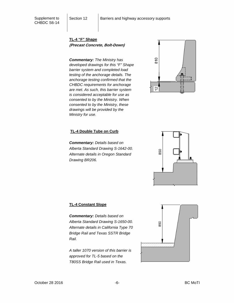
TL-4 “F” Shape (Precast Concrete, Bolt-Down)
Commentary: The Ministry has developed drawings for this “F” Shape barrier system and completed load testing of the anchorage details. The anchorage testing confirmed that the CHBDC requirements for anchorage are met. As such, this barrier system is considered acceptable for use as consented to by the Ministry. When consented to by the Ministry, these drawings will be provided by the Ministry for use.
TL-4 Double Tube on Curb Commentary: Details based on Alberta Standard Drawing S-1642-00. Alternate details in Oregon Standard Drawing BR206.
TL-4 Constant Slope Commentary: Details based on Alberta Standard Drawing S-1650-00. Alternate details in California Type 70 Bridge Rail and Texas SSTR Bridge Rail. A taller 1070 version of this barrier is approved for TL-5 based on the T80SS Bridge Rail used in Texas.

Supplement to CHBDC S6-14
Section 12 Barriers and highway accessory supports
October 28 2016 -7- BC MoTI
TL-4 Vertical Face Commentary: Details based on the Texas T221 Bridge Rail.
TL-5 “F” Shape This is an extended version of the Ministry’s Standard Bridge Parapet (2874-1). Barrier, anchorage and deck reinforcing shall be increased in proportion to the loads listed in Table 3.8 of the CHBDC. Commentary: This barrier also meets the height requirements for a pedestrian barrier.
Commentary: Resources for further information for both the noted reference concepts and other barrier concepts include:
- Guide to Bridge Traffic and Combination Barriers (2010), Transportation Association of Canada
- Online Guide to Bridge Railings, (on-going project), AASHTO-ARTBA-AGC Task Force 13 (http://guides.roadsafellc.com/bridgeRailGuide/)
- Standard drawings published on provincial and state web sites
Supplement to CHBDC S6-14
Section 12 Barriers and highway accessory supports
October 28 2016 -8- BC MoTI
12.4.3.2.5 Test level for barriers on low volume roads
Delete and replace with the following:
For bridges that meet the Ministry definition of a Low Volume Road Structure and that also meet the following criteria, then a TL-1 barrier system may be used:
• Bridges on a road with a maximum roadway width of 8.6 m, a maximum deck height above ground or water surface of 5.0 m, and either a maximum design speed of 80 km/h combined with a maximum AADT of 100 or a maximum design speed of 50 km/h combined with a maximum AADT of 400.
For other bridges that meet the Ministry definition of a Low Volume Road Structure, Test Level 2, 4, or 5, determined in accordance with Clauses 12.4.3.2.3 and 12.4.3.2.4, shall be used unless alternative test levels are Approved. Barrier anchorage loads for Test Level 1 shall be determined in accordance with Clause 12.4.3.5. Barrier anchorage loads specified for Test Level 1 in Table 3.7 may be reduced by 20%.
Commentary: See CL. 1.3.3 of this Supplement for the Ministry’s definition of a Low Volume Road Structure.
12.4.3.3 Geometry and end treatment details
Traffic barriers shall be constructed such they are oriented perpendicular to the deck surface.
In Table 12.8 - Minimum barrier heights, change height H to 0.81 m for traffic barrier type TL-4.
Commentary: Traffic barriers are constructed perpendicular to the deck surface in order that the roadway face of the barrier remains correctly oriented to withstand vehicle impacts which may be inclined due to deck crossfall. This also avoids discontinuities in the barrier faces at bridge ends where parapets meet transition barriers.
12.4.3.5 Anchorages
Commentary: Note that a live load factor of 1.7 shall be applied to the barrier loads specified in Clause 3.8.8.

Supplement to CHBDC S6-14
Section 12 Barriers and highway accessory supports
October 28 2016 -9- BC MoTI
12.4.4 Pedestrian barriers
12.4.4.1 General
The Ministry’s Standard steel sidewalk fence shall be used (Standard Drawing 2891-1). The standard steel sidewalk fence shall extend a minimum of three (3) metres beyond the back of ballast wall at bridge abutments or extend a minimum of three (3) metres beyond the ends of return walls, as appropriate.
Debris and/or safety fence shall be installed when directed by the Ministry.
Commentary: The debris and/or safety fencing should be considered in urban areas for bridges over roadways to reduce the risk of objects falling from the bridge on to the roadway below.
12.4.4.2 Geometry
Pedestrian barriers shall be constructed such that they are oriented plumb.
Figure 12.2 – Geometry of side-mounted pedestrian and bicycle barriers
Revise as follows:
12.4.5 Bicycle barriers
12.4.5.1 General
The Ministry Standard steel bicycle fence shall be used (refer to Standard Drawing 2891-2). The standard steel bicycle fence shall extend a minimum of three (3) metres beyond the back of ballast wall at bridge abutments or extend a minimum of three (3) metres beyond the ends of return walls, as appropriate.
12.4.5.2 Geometry
Bicycle barriers shall be constructed such that they are oriented plumb.
100 mm max

Supplement to CHBDC S6-14
Section 12 Barriers and highway accessory supports
October 28 2016 -10- BC MoTI
Commentary: Alternatives to the Ministry’s Standard steel sidewalk or bicycle fence may be considered when debris being thrown from the bridge or people climbing the fence are identified as site specific issues. Jurisdictions with facilities under Ministry structures, such as railways, may have requirements for protective screening that include height of screen, size of openings and length.
12.4.6 Combination barriers
12.4.6.1.a Configuration of combination barriers
The configuration of bridge traffic and combination barriers depends on the roadway type and the makeup of its users. In general, the bridge barrier design shall match one of the three following configurations, each described in the appended illustrations.
- Configuration #1 - Bridge with No Sidewalk
- Configuration #2 - Bridge with Raised Sidewalk
- Configuration #3 - Bridge with Sidewalk Separated by a Barrier
Commentary: For sides of bridges where there is no sidewalk, Combination Barriers are installed at the outside of the bridge for the safety and protection of pedestrian and/or bicycle traffic on the bridge deck.
For bridges with sidewalk(s), it is left to the Design Engineer to determine the most suitable type of separation based on anticipated traffic volumes and details of the crossing. In general, concrete parapet type barriers are used to separate the roadway from the sidewalk(s). The sidewalk face of the barrier shall have a smooth surface without snag points.
The installation of Combination Barriers is an additional cost item for bridges having no provision for sidewalks. In remote areas, where pedestrian and bicycle traffic is minimal, Traffic Barriers may possibly be used in lieu of Combination Barriers.
12.4.6.1.b Pedestrian combination barriers
The following pedestrian combination barrier “reference concepts” have been accepted by the Ministry for use on highway bridges in B.C. Other pedestrian combination barrier concepts may be considered but require prior Approval.
All pedestrian combination barrier designs shall meet the CHBDC requirements for crash testing. Each of the listed “reference concepts” is known to have met the CHBDC requirements for crash testing. Jurisdictional usage for each listed “reference concept” is included. The Design Engineer shall confirm the applicability of the of the “reference concept” with respect to crash testing, usage and detailing.

Supplement to CHBDC S6-14
Section 12 Barriers and highway accessory supports
October 28 2016 -11- BC MoTI
TL-4 “F” Shape with Pedestrian Railing See the Ministry’s Standard Bridge Parapet (2874-1) for barrier detail. See the Ministry’s Standard Bridge Parapet Steel Railing (2785-2) for railing detail.
TL-4 “Tall F” or TL-5 “F” Shape This is an extended version of the Ministry’s Standard Bridge Parapet (2874-1). Commentary: The Ministry’s TL-5 “F” Shape inherently provides pedestrian-height protection. The barrier can be detailed for TL-4 loading, as required. TL-4 3-Tube on Curb Commentary: Details based on Oregon Standard Drawing BR208.

Supplement to CHBDC S6-14
Section 12 Barriers and highway accessory supports
October 28 2016 -12- BC MoTI
12.4.6.1.c Bicycle combination barriers
The following bicycle combination barrier “reference concepts” have been accepted by the Ministry for use on highway bridges in B.C. Other bicycle combination barrier concepts may be considered but require prior Approval.
All bicycle combination barrier designs shall meet the CHBDC requirements for crash testing. Each of the listed “reference concepts” is known to have met the CHBDC requirements for crash testing. Jurisdictional usage for each listed “reference concept” is included. The Design Engineer shall confirm the applicability of the of the “reference concept” with respect to crash testing, usage and detailing.
TL-4 “F” Shape with Bicycle Railing See the Ministry’s Standard Bridge Parapet (2874-1) for barrier detail. See the Ministry’s Standard Bridge Parapet Steel Bicycle Railing (2785-3) for railing detail.

Supplement to CHBDC S6-14
Section 12 Barriers and highway accessory supports
October 28 2016 -13- BC MoTI
TL-4 “F” Shape with Flush-Post Bicycle Railing See the Ministry’s Standard Bridge Parapet (2874-1) for barrier detail. Commentary: A flush post railing is preferred when a railing is required on top of a barrier that separates traffic from a mixed-used sidewalk.
TL-4 “Tall F” or TL-5 “F” Shape with Pedestrian Railing This is an extended version of the Ministry’s Standard Bridge Parapet (2874-1). See the Ministry’s Standard Bridge Parapet Steel Railing (2785-2) for railing detail. Commentary: A protection height of 1350mm is 20mm below the CHBDC minimum requirement for bicycle protection. This reduction in protection height is acceptable for this reference concept only.
12.4.6.2 Geometry
Where combination barriers are installed on sidewalks separated from traffic by raised curbs, the barriers shall be constructed such they are oriented plumb. Otherwise, where combination barriers are installed on the bridge deck, barriers shall be constructed such that they are oriented perpendicular to the deck surface.
Commentary: Combination barriers installed on bridge decks are constructed perpendicular to the deck surface in order that the roadway face of the barrier remains correctly oriented to withstand vehicle impacts.

NOTES:
1. TRAFFIC BARRIER PROTECTION BASED ON THE MINISTRY'S STANDARD BRIDGE PARAPET. OTHER BARRIERS MAY BE ACCEPTABLE.
2. THE USE OF A TRAFFIC BARRIER (OPTION A) IN LIEU OF A COMBINATION BARRIER MAY BE ACCEPTABLE IN REMOTE AREAS, AS RECOMMENDED BY THE DESIGN
ENGINEER AND AS CONSENTED TO BY THE MINISTRY, ON THE BASIS OF THE ANTICIPATED VOLUME OF PEDESTRIAN AND/OR BICYCLE TRAFFIC AND GEOMETRIC
DETAILS OF THE CROSSING.
3. ALL DIMENSIONS ARE IN MILLIMETRES UNLESS NOTED OTHERWISE.
October 28 2016BC MoTI Supplement to CHBDC S6-14 - Section 12
CONFIGURATION #1 - BRIDGE WITH NO SIDEWALK

NOTES:
1. TRAFFIC BARRIER HAS VERTICAL FACE SINCE THE MINISTRY'S STANDARD BRIDGE PARAPET IS NOT DESIGNED TO BE MOUNTED ON A CURB. OTHER BARRIERS
MAY BE ACCEPTABLE.
2. ALL DIMENSIONS ARE IN MILLIMETRES UNLESS NOTED OTHERWISE.
3. CURBS SHOULD BE NO HIGHER THAN 200mm.
October 28 2016BC MoTI Supplement to CHBDC S6-14 - Section 12
CONFIGURATION #2 - BRIDGE WITH RAISED SIDEWALK

NOTES:
1. TRAFFIC BARRIER BASED ON THE MINISTRY'S STANDARD BRIDGE PARAPET. OTHER
BARRIERS MAY BE ACCEPTABLE. PEDESTRIAN AND BICYCLE BRIDGE BASED ON
THE MINISTRY'S STANDARD STEEL SIDEWALK AND BRIDGE FENCE, RESPECTIVELY.
2. ALL DIMENSIONS ARE IN MILLIMETRES UNLESS NOTED OTHERWISE.
LEGEND
*
~
October 28 2016BC MoTI Supplement to CHBDC S6-14 - Section 12
CONFIGURATION #3 - BRIDGE WITH SIDEWALK SEPARATED BY A BARRIER