primergy tx150 s6 server - fujitsu technology...
TRANSCRIPT
PRIMERGY TX150 S6 Server Service Supplement
Edition February 2008
Comments… Suggestions… Corrections…The User Documentation Department would like toknow your opinion of this manual. Your feedback helpsus optimize our documentation to suit your individual needs.
Feel free to send us your comments by e-mail to [email protected].
Certified documentation according to DIN EN ISO 9001:2000To ensure a consistently high quality standard anduser-friendliness, this documentation was created tomeet the regulations of a quality management system which complies with the requirements of the standardDIN EN ISO 9001:2000.
cognitas. Gesellschaft für Technik-Dokumentation mbHwww.cognitas.de
Copyright and TrademarksCopyright © 2008 Fujitsu Siemens Computers GmbH.
All rights reserved.Delivery subject to availability; right of technical modifications reserved.
All hardware and software names used are trademarks of their respective manufacturers.
TX150 S6 Service Supplement
Contents
1 Introduction . . . . . . . . . . . . . . . . . . . . . . . . . . . . 5
1.1 Overview of the documentation . . . . . . . . . . . . . . . . . 5
1.2 Notational conventions . . . . . . . . . . . . . . . . . . . . . 8
2 Procedure . . . . . . . . . . . . . . . . . . . . . . . . . . . . . 9
3 Safety notes . . . . . . . . . . . . . . . . . . . . . . . . . . 11
4 Replacement routines . . . . . . . . . . . . . . . . . . . . . 17
4.1 Preparation . . . . . . . . . . . . . . . . . . . . . . . . . . . 174.1.1 Floorstand model . . . . . . . . . . . . . . . . . . . . . . . . 174.1.1.1 Opening the server . . . . . . . . . . . . . . . . . . . . . . 174.1.1.2 Removing the front cover . . . . . . . . . . . . . . . . . . 174.1.2 Rack model . . . . . . . . . . . . . . . . . . . . . . . . . . . 184.1.2.1 Opening the server . . . . . . . . . . . . . . . . . . . . . . 184.1.2.2 Removing the rack front cover . . . . . . . . . . . . . . . . 18
4.2 Replacing the operating panel module . . . . . . . . . . . . 19
4.3 Replacing the standard PS . . . . . . . . . . . . . . . . . . 20
4.4 Replacing the Power backplane . . . . . . . . . . . . . . . . 22
4.5 Replacing the 3.5“ SAS/SATA backplane . . . . . . . . . . . 23
4.6 Replacing the 2.5“ SAS backplane . . . . . . . . . . . . . . 24
4.7 Replacing the IDTEMP combo . . . . . . . . . . . . . . . . . 26
4.8 Replacing the intrusion switches . . . . . . . . . . . . . . . 28
4.9 Replacing the processor . . . . . . . . . . . . . . . . . . . . 30
4.10 Replacing the system board . . . . . . . . . . . . . . . . . . 35
Service Supplement TX150 S6
Contents
5 Appendix . . . . . . . . . . . . . . . . . . . . . . . . . . . . . 39
5.1 Board layout . . . . . . . . . . . . . . . . . . . . . . . . . . . 395.1.1 Operating panel board . . . . . . . . . . . . . . . . . . . . . . 395.1.2 3.5“ SAS/SATA backplane . . . . . . . . . . . . . . . . . . . . 405.1.3 2.5“ SAS backplane . . . . . . . . . . . . . . . . . . . . . . . . 415.1.4 Power backplane . . . . . . . . . . . . . . . . . . . . . . . . . 42
Index . . . . . . . . . . . . . . . . . . . . . . . . . . . . . . . . . . . . 43
TX150 S6 Service Supplement 5
1 IntroductionThe PRIMERGY TX150 S6 Server is an Intel-based server for small- and medium-sized networks. The server is suitable for use as a file server and also as an application, information or Internet server. It is available as a floorstand or rack model. The floorstand model can be converted to a rack model using an optional conversion kit.
1.1 Overview of the documentation
Concept and target groups
This Service Supplement completes the information given in the Operating Manual, the Options Guide and the Technical Manual of the system board.
The activities described in this manual may only be performed by service personnel.
Service DVD
Service partners of Fujitsu Siemens can order a Service DVD PRIMERGY. On the DVD the following manuals are available in pdf format:
– The “Safety notes and other important information” manual– The Operating Manual for PRIMERGY TX150 S6– The Technical Manual for the system board D2559– The Options Guide for PRIMERGY TX150 S6– The Service Supplement PRIMERGY TX150 S6– The “BIOS Setup” manual
6 Service Supplement TX150 S6
Overview of the documentation Introduction
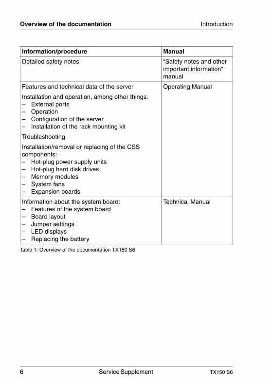
Information/procedure Manual
Detailed safety notes “Safety notes and other important information“ manual
Features and technical data of the server Operating Manual
Installation and operation, among other things:– External ports– Operation– Configuration of the server– Installation of the rack mounting kit
Troubleshooting
Installation/removal or replacing of the CSS components:– Hot-plug power supply units– Hot-plug hard disk drives– Memory modules– System fans– Expansion boards
Information about the system board:– Features of the system board– Board layout– Jumper settings– LED displays– Replacing the battery
Technical Manual
Table 1: Overview of the documentation TX150 S6
TX150 S6 Service Supplement 7
Introduction Overview of the documentation
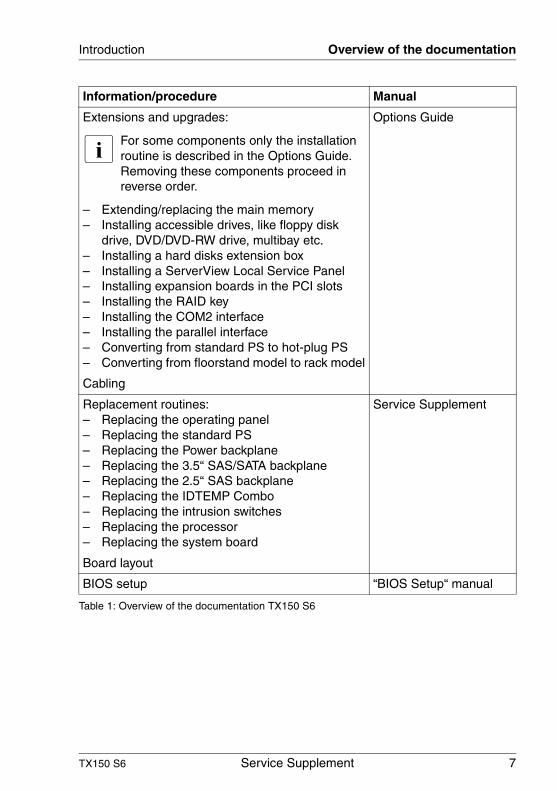
Extensions and upgrades:
I For some components only the installation routine is described in the Options Guide. Removing these components proceed in reverse order.
– Extending/replacing the main memory– Installing accessible drives, like floppy disk
drive, DVD/DVD-RW drive, multibay etc.– Installing a hard disks extension box– Installing a ServerView Local Service Panel– Installing expansion boards in the PCI slots– Installing the RAID key– Installing the COM2 interface– Installing the parallel interface– Converting from standard PS to hot-plug PS– Converting from floorstand model to rack model
Options Guide
Cabling
Replacement routines:– Replacing the operating panel– Replacing the standard PS– Replacing the Power backplane– Replacing the 3.5“ SAS/SATA backplane– Replacing the 2.5“ SAS backplane– Replacing the IDTEMP Combo– Replacing the intrusion switches– Replacing the processor– Replacing the system board
Service Supplement
Board layout
BIOS setup “BIOS Setup“ manual
Information/procedure Manual
Table 1: Overview of the documentation TX150 S6
8 Service Supplement TX150 S6
Notational conventions Introduction
1.2 Notational conventions
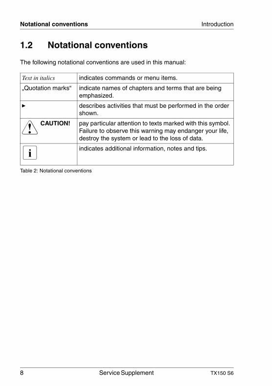
The following notational conventions are used in this manual:
Text in italics indicates commands or menu items.
„Quotation marks“ indicate names of chapters and terms that are being emphasized.
Ê describes activities that must be performed in the order shown.
V CAUTION! pay particular attention to texts marked with this symbol. Failure to observe this warning may endanger your life, destroy the system or lead to the loss of data.
I indicates additional information, notes and tips.
Table 2: Notational conventions
TX150 S6 Service Supplement 9
2 ProcedureV CAUTION!
The actions described in these instructions should only be performed by service personnel.
Ê First of all please familiarize yourself with the safety instructions in the section chapter “Safety notes” on page 11 et seq. .
Ê Ensure that all required manuals (see Service DVD) are available, printing out the PDF files if necessary. You will definitely need the Operating Manual for the server, the Options Guide for the server and the Technical Manual for the system board.
Ê Shut down the server correctly, switch it off, pull out the power plug, and open the server as described in the chapter “Replacement routines” on page 17 et seq. .
Ê Replace the defective component as described in the relevant chapter.
I Procedures which are identical for the floorstand and rack models are only described for the floorstand model.
Ê Close the server.1
Ê Connect the cables. 1
Ê Connect the server to the power outlet.1
Ê Start the operating system.1
Ê If necessary, configure the server as required.1
1 These procedures are described in the Operating Manual.

TX150 S6 Service Supplement 11
3 Safety notesI The following safety notes are also provided in the “Safety notes and
other important information” manual.
This device complies with the relevant safety regulations for data processing equipment.
V CAUTION!
The actions described in these instructions should only be performed by service personnel.
Before operating the device
V CAUTION!
● During installation and before operating the device, observe the instructions on environmental conditions for your device.
● If the device is brought in from a cold environment, condensation may form both inside and on the outside of the machine.
Wait until the device has acclimatized to room temperature and is absolutely dry before starting it up. Material damage may be caused to the device if this requirement is not observed.
● Transport the device only in the original packaging or in packaging that protects it from knocks and jolts.
Installation and operation
V CAUTION!
● If the rack model is integrated in an installation that receives power from an industrial (public) power supply network with the IEC309 connector, the (public) power supply protection must comply with the requirements for the non-industrial (public) power supply networks for the type A connector.
● The server automatically sets itself to a voltage in the range of 100 V to 240 V. Make sure that your local voltage is within this range.
12 Service Supplement TX150 S6
Safety notes
V CAUTION!
● This device has a specially approved power cable and must only be connected to a grounded insulated socket (floorstand model) respec-tively to a safety socket on the rack mains socket strip (rack model).
● Ensure that the power socket on the device or the grounded wall outlet is freely accessible.
● The ON/OFF button does not disconnect the device from the mains voltage. To disconnect the line voltage completely, remove the power plug from the power socket.
● Always connect the device and the attached peripherals to the same power circuit. Otherwise you run the risk of losing data if, for example, the server is still operating but the peripheral device (e.g. storage subsystem) has failed during a power outage.
● Take notice that the data cables to peripheral devices are adequately shielded.
● To the LAN wiring the requirements apply in accordance with the standards EN 50173 and EN 50174-1/2. As minimum requirement the use of a protected LAN line of category 5 for 10/100 MBps Ethernet, and/or of category 5e for Gigabit Ethernet is considered. The requirements of the specification ISO/IEC 11801 are to be considered.
● Route the cables in such a way that they do not form a potential hazard (make sure no-one can trip over them) and that they cannot be damaged. When connecting up a device, refer to the relevant notes in this manual.
● Never connect or disconnect data transmission lines during a storm (lightning hazard).
● Make sure that no objects (such as bracelets or paper clips) fall into or liquids spill into the device (risk of electric shock or short circuit).
● In emergencies (e.g. damaged casing, controls or cables, penetration of liquids or foreign matter), switch off the device immediately and remove the power plug.
TX150 S6 Service Supplement 13
Safety notes
V CAUTION!
● Proper operation of the device (in accordance with IEC 60950-1/EN 60950-1) is only ensured if the casing is completely assembled and the rear covers for the installation openings have been put in place (electric shock, cooling, fire protection, interference suppression).
● Install only system expansions that satisfy the requirements and rules governing safety and electromagnetic compatibility and relating to telecommunications terminal equipment. If you install other expan-sions, you may damage the system or violate the safety regulations and regulations governing RFI suppression.
● The components or parts marked with a warning label (e.g. lightning symbol) may only be opened, removed or exchanged by authorized, qualified personnel. The hot-plug power supply units are exceptions to this rule.
● The warranty expires if the device is damaged during the installation or replacement of system expansions.
● You may only set those resolutions and refresh rates specified in the „Technical data“ section of the monitor description. Otherwise, you may damage the monitor.
Batteries
V CAUTION!
● Incorrect replacement of batteries may lead to a risk of explosion. The batteries may only be replaced with identical batteries or with a type recommended by the manufacturer (see the Technical Manual for the system board).
● Do not throw batteries into the trash can. They must be disposed of in accordance with local regulations concerning special waste.
● The battery must be disposed of in accordance with local regulations concerning special waste.

14 Service Supplement TX150 S6
Safety notes
V CAUTION!
● Replace the lithium battery on the system board in accordance with the instructions in the Technical Manual for the system board.
● All batteries containing pollutants are marked with a symbol (a crossed-out garbage can). In addition, the marking is provided with the chemical symbol of the heavy metal decisive for the classification as a pollutant:
Cd Cadmium Hg Mercury Pb Lead
Working with CDs/DVDs and CD/DVD drives
When working with devices with CD/DVD drives, these instructions must be followed.
V CAUTION!
● Only use CDs/DVDs that are in perfect condition in your server's CD/DVD drive, in order to prevent data loss, equipment damage and injury.
● Check each CD/DVD for damage, cracks, breakages etc. before inserting it in the drive.
Note that any additional labels applied may change the mechanical properties of a CD/DVD and cause imbalance.
Damaged and imbalanced CDs/DVDs can break at high drive speeds (data loss).
Under certain circumstances, sharp CD/DVD fragments can pierce the cover of the CD/DVD drive (equipment damage) and can fly out of the device (danger of injury, particularly to uncovered body parts such as the face or neck).
I You can prevent mechanical damage and damage to the CD/DVD drive, as well as premature CD/DVD wear, by observing the following sugges-tions:
● Only insert CDs/DVDs in the drive when needed and remove them after use.
● Store the CDs/DVDs in suitable sleeves.

TX150 S6 Service Supplement 15
Safety notes
● Protect the CDs/DVDs from exposure to heat and direct sunlight.
I Laser information
The CD/DVD drive complies with IEC 60825-1 laser class 1.
V CAUTION!
The CD/DVD drive contains a light-emitting diode (LED), which under certain circumstances produces a laser beam stronger than laser class 1. Looking directly at this beam is dangerous.
Never remove parts of the CD/DVD drive casing!
Modules with electrostatic-sensitive components:
Systems and components that might be damaged by electrostatic discharge (ESD) are marked with the following label:
Figure 1: ESD label
When you handle components fitted with ESDs, you must observe the following points under all circumstances:
● Remove the power plug from the power socket before inserting or removing components containing ESDs.
● You must always discharge yourself of static charges (e.g. by touching a grounded object) before working.
● The equipment and tools you use must be free of static charges.
● Only touch the components at the positions highlighted in green (touch points).
● Do not touch any exposed pins or conductors on a component.
16 Service Supplement TX150 S6
Safety notes
● Use a grounding cable designed for this purpose to connect yourself to the system unit as you install components.
● Place all components on a static-safe base.
I You will find a detailed description for handling ESD components in the relevant European or international standards (DIN EN 61340-5-1, ANSI/ESD S20.20).
TX150 S6 Service Supplement 17
4 Replacement routinesV CAUTION!
Observe the safety instructions in the chapter “Safety notes” on page 11 et seq. .
4.1 Preparation
4.1.1 Floorstand model
I You will find a detailed description of “Opening the server“ and “Removing the front cover“ in the Options Guide TX150 S6.
4.1.1.1 Opening the server
Ê Terminate all applications and shut down the server correctly.
Ê If your operating system has not switched off the server, press the on/off switch for at least four seconds (“Power override“ function).
Ê Pull all power connectors out of the power outlets.
Ê If required, remove the lock on the side cover.
Ê Unlock the server.
Ê Loosen the two knurled screws at the server’s rear side.
Ê Push back the left-hand side cover approxiate 2 cm.
Ê Remove the left-hand side cover.
4.1.1.2 Removing the front cover
Remove the front cover when making the following replacements:– Replacing the operating panel– Replacing the DVD/DVD-RW drive– Replacing the intrusion switches
Ê Push the drive cover up as far as possible.
Ê Remove the hard disk cover.
18 Service Supplement TX150 S6
Preparation Replacement routines
Ê Disengage the three tabs on the left side one after the other and rotate the front cover outward about 2 cm.
Ê Press the two touch points of the lower hooks inward.
Ê Push the drive cover downward.
Ê Press strongly on the upper right cant of the front cover to release the upper hook and pull out the front cover sideward.
4.1.2 Rack model
I You will find a detailed description of “Opening the server“ and “Removing the rack front cover“ in the Options Guide TX150 S6.
Ê Terminate all applications and shut down the server correctly.
Ê If your operating system has not switched off the server, press the on/off button for at least four seconds (“Power override“ function).
Ê Pull all power connectors out of the power outlets.
4.1.2.1 Opening the server
Ê Loosen the four knurled screws and pull the server as far as possible out of the rack.
Depending on how accessible the server is in the rack cabinet, it can make sense to remove it from the cabinet. You will find a detailed description in the Options Guide or the Operating Manual.
Ê Loosen the two knurled screws at the server’s rear side.
Ê Push back the top cover approxiate 2 cm.
Ê Remove the top cover.
4.1.2.2 Removing the rack front cover
Remove the rack front cover when making the following replacements:– Replacing the operating panel– Replacing the DVD/DVD-RW drive– Replacing the intrusion switches
Ê Remove two screws on either side.
TX150 S6 Service Supplement 19
Replacement routines Replacing the operating panel module
Ê Remove the rack front cover to the front.
Ê Disengage the three tabs on the top side one after the other and pull out the plastic front cover frontward about 2 cm.
Ê Press the three hooks on the bottom side downward and pull out the plastic front cover frontward.
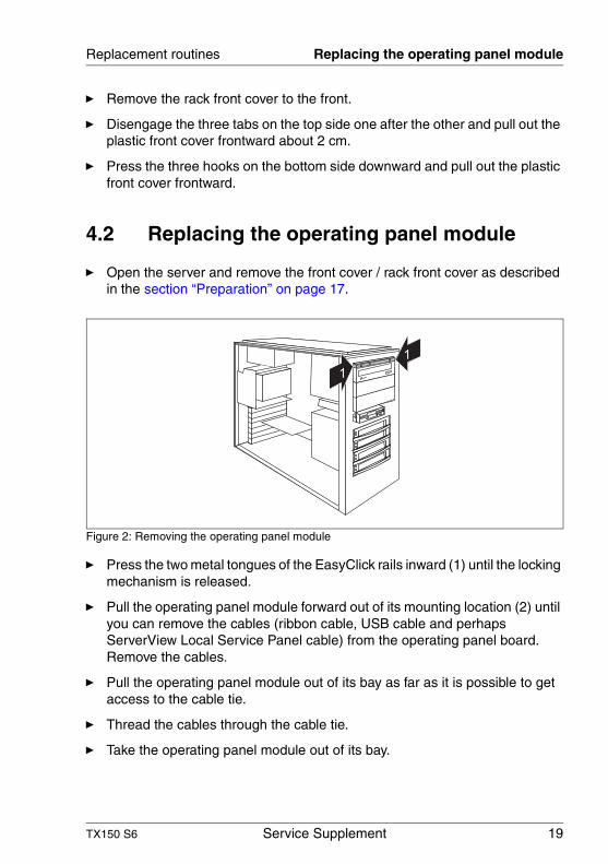
4.2 Replacing the operating panel module
Ê Open the server and remove the front cover / rack front cover as described in the section “Preparation” on page 17.
Figure 2: Removing the operating panel module
Ê Press the two metal tongues of the EasyClick rails inward (1) until the locking mechanism is released.
Ê Pull the operating panel module forward out of its mounting location (2) until you can remove the cables (ribbon cable, USB cable and perhaps ServerView Local Service Panel cable) from the operating panel board. Remove the cables.
Ê Pull the operating panel module out of its bay as far as it is possible to get access to the cable tie.
Ê Thread the cables through the cable tie.
Ê Take the operating panel module out of its bay.
1
1
20 Service Supplement TX150 S6
Replacing the standard PS Replacement routines
Ê Push the new operating panel module into its bay as far as it is possible to have access to the cable tie.
Ê Thread the cables through the cable tie.
Ê Push the operating panel module into its bay as far as it is possible to plug the cables.
Ê Connect the cables (ribbon cable, USB cable and perhaps ServerView Local Service Panel cable) to the operating panel board (see the board layout on page 39).
Ê Push the operating panel module into the housing until it engages.
Ê Close the server and connect all power plugs (for a detailed description see the Options Guide).
4.3 Replacing the standard PS
Ê Open the server as described in the section “Preparation” on page 17.
I You can replace the power supply without removing the adapter plate.
Ê Disconnect all power cables from the system board and the drives (see the cabling plans in the Options Guide).
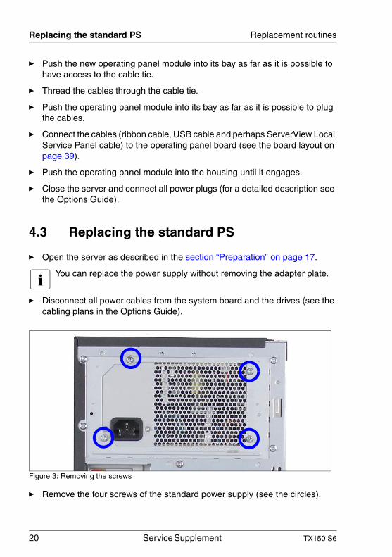
Figure 3: Removing the screws
Ê Remove the four screws of the standard power supply (see the circles).
TX150 S6 Service Supplement 21
Replacement routines Replacing the standard PS
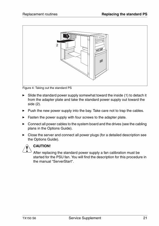
Figure 4: Taking out the standard PS
Ê Slide the standard power supply somewhat toward the inside (1) to detach it from the adapter plate and take the standard power supply out toward the side (2).
Ê Push the new power supply into the bay. Take care not to trap the cables.
Ê Fasten the power supply with four screws to the adapter plate.
Ê Connect all power cables to the system board and the drives (see the cabling plans in the Options Guide).
Ê Close the server and connect all power plugs (for a detailed description see the Options Guide).
V CAUTION!
After replacing the standard power supply a fan calibration must be started for the PSU fan. You will find the description for this procedure in the manual “ServerStart“.
2
1
22 Service Supplement TX150 S6
Replacing the Power backplane Replacement routines
4.4 Replacing the Power backplane
The Power backplane is mounted on the PS cage. The power cables are permanently connected to the Power backplane.
Ê Open the server as described in the section “Preparation” on page 17.
Ê Push the green latch of the hot-plug power supply unit upward and pull the power supply unit simultaneously out of the PS cage using the handle (see also the Operating Manual).
Ê If a second hot-plug power supply unit has been installed, remove this one in the same way (if there is a dummy cover instead of a second hot-plug power supply unit, this can remain in place).
I The Power backplane in the floorstand model is positioned directly under the top cover and it makes sense to lay the server on a table with the uncovered side facing upward. Place the server in such a way that the feet can project over the edge.
Ê Remove all power cables from the system board and the drives (see the cabling plans in the Options Guide).
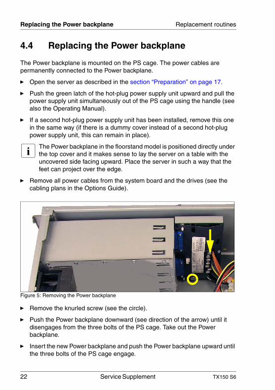
Figure 5: Removing the Power backplane
Ê Remove the knurled screw (see the circle).
Ê Push the Power backplane downward (see direction of the arrow) until it disengages from the three bolts of the PS cage. Take out the Power backplane.
Ê Insert the new Power backplane and push the Power backplane upward until the three bolts of the PS cage engage.
TX150 S6 Service Supplement 23
Replacement routines Replacing the 3.5“ SAS/SATA backplane
Ê Fasten the Power backplane with the knurled screw in the PS cage.
Ê Plug the power cables on the system board and the drives (see the cabling plans in the Options Guide).
Ê Reinstall the hot-plug power supply unit(s).
Ê Close the server and connect all power plugs (for a detailed description see the Options Guide).
4.5 Replacing the 3.5“ SAS/SATA backplane
The 3.5“ SAS/SATA backplane is mounted on the hard disk cage. It is not necessary to remove the hard disk cage before replacing the SAS/SATA backplane.
Ê Open the server as described in the section “Preparation” on page 17.
Ê Remove all the hot-plug hard disk drives (for a description see the Operating Manual).
V CAUTION!
Check if all hard disk drives are uniquely identified so that you can reinsert them into their original bays.
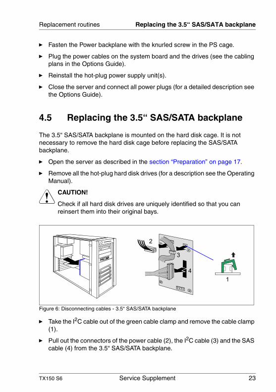
Figure 6: Disconnecting cables - 3.5“ SAS/SATA backplane
Ê Take the I2C cable out of the green cable clamp and remove the cable clamp (1).
Ê Pull out the connectors of the power cable (2), the I2C cable (3) and the SAS cable (4) from the 3.5“ SAS/SATA backplane.
1
2
3
4
24 Service Supplement TX150 S6
Replacing the 2.5“ SAS backplane Replacement routines
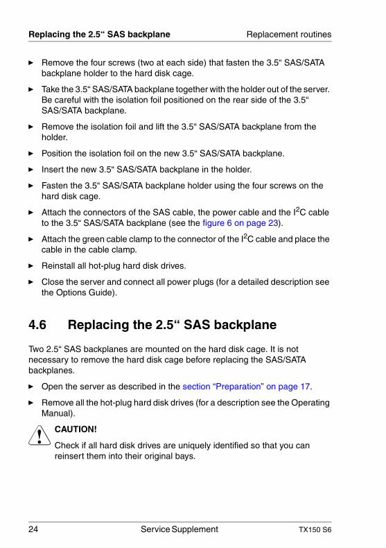
Ê Remove the four screws (two at each side) that fasten the 3.5“ SAS/SATA backplane holder to the hard disk cage.
Ê Take the 3.5“ SAS/SATA backplane together with the holder out of the server. Be careful with the isolation foil positioned on the rear side of the 3.5“ SAS/SATA backplane.
Ê Remove the isolation foil and lift the 3.5“ SAS/SATA backplane from the holder.
Ê Position the isolation foil on the new 3.5“ SAS/SATA backplane.
Ê Insert the new 3.5“ SAS/SATA backplane in the holder.
Ê Fasten the 3.5“ SAS/SATA backplane holder using the four screws on the hard disk cage.
Ê Attach the connectors of the SAS cable, the power cable and the I2C cable to the 3.5“ SAS/SATA backplane (see the figure 6 on page 23).
Ê Attach the green cable clamp to the connector of the I2C cable and place the cable in the cable clamp.
Ê Reinstall all hot-plug hard disk drives.
Ê Close the server and connect all power plugs (for a detailed description see the Options Guide).
4.6 Replacing the 2.5“ SAS backplane
Two 2.5“ SAS backplanes are mounted on the hard disk cage. It is not necessary to remove the hard disk cage before replacing the SAS/SATA backplanes.
Ê Open the server as described in the section “Preparation” on page 17.
Ê Remove all the hot-plug hard disk drives (for a description see the Operating Manual).
V CAUTION!
Check if all hard disk drives are uniquely identified so that you can reinsert them into their original bays.
TX150 S6 Service Supplement 25
Replacement routines Replacing the 2.5“ SAS backplane
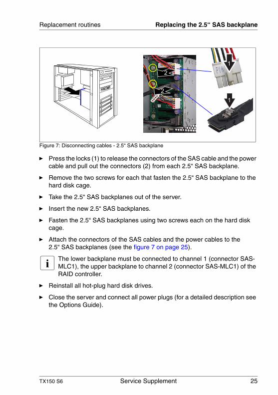
Figure 7: Disconnecting cables - 2.5“ SAS backplane
Ê Press the locks (1) to release the connectors of the SAS cable and the power cable and pull out the connectors (2) from each 2.5“ SAS backplane.
Ê Remove the two screws for each that fasten the 2.5“ SAS backplane to the hard disk cage.
Ê Take the 2.5“ SAS backplanes out of the server.
Ê Insert the new 2.5“ SAS backplanes.
Ê Fasten the 2.5“ SAS backplanes using two screws each on the hard disk cage.
Ê Attach the connectors of the SAS cables and the power cables to the 2.5“ SAS backplanes (see the figure 7 on page 25).
I The lower backplane must be connected to channel 1 (connector SAS-MLC1), the upper backplane to channel 2 (connector SAS-MLC1) of the RAID controller.
Ê Reinstall all hot-plug hard disk drives.
Ê Close the server and connect all power plugs (for a detailed description see the Options Guide).
1
2
2
1
26 Service Supplement TX150 S6
Replacing the IDTEMP combo Replacement routines
4.7 Replacing the IDTEMP combo
This board includes two important system components:
– EEPROM for the chassis ID and ident number of the server– temperature sensor for monitoring the environment temperature
The current temperature values and EEPROM data are transmitted to the system board via the connected I2C bus.
The IDTEMP combo must be correctly installed in order:
– to monitor the temperature correctly,– to enable the server management to display the correct system picture,– to install the server using ServerStart.
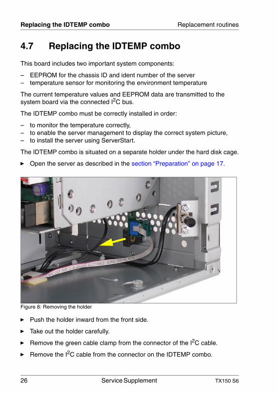
The IDTEMP combo is situated on a separate holder under the hard disk cage.
Ê Open the server as described in the section “Preparation” on page 17.
Figure 8: Removing the holder
Ê Push the holder inward from the front side.
Ê Take out the holder carefully.
Ê Remove the green cable clamp from the connector of the I2C cable.
Ê Remove the I2C cable from the connector on the IDTEMP combo.
TX150 S6 Service Supplement 27
Replacement routines Replacing the IDTEMP combo
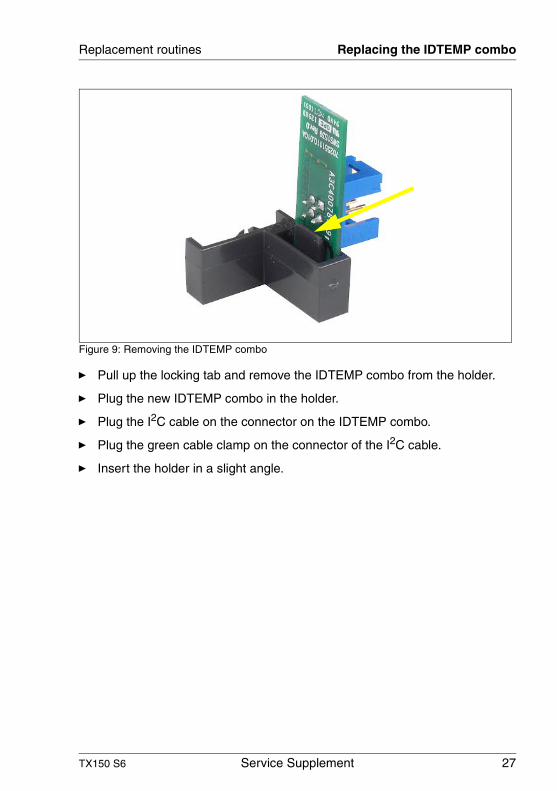
Figure 9: Removing the IDTEMP combo
Ê Pull up the locking tab and remove the IDTEMP combo from the holder.
Ê Plug the new IDTEMP combo in the holder.
Ê Plug the I2C cable on the connector on the IDTEMP combo.
Ê Plug the green cable clamp on the connector of the I2C cable.
Ê Insert the holder in a slight angle.
28 Service Supplement TX150 S6
Replacing the intrusion switches Replacement routines
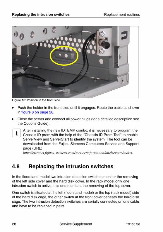
Figure 10: Position in the front side
Ê Push the holder in the front side until it engages. Route the cable as shown in figure 8 on page 26.
Ê Close the server and connect all power plugs (for a detailed description see the Options Guide).
I After installing the new IDTEMP combo, it is necessary to program the Chassis ID prom with the help of the "Chassis ID Prom Tool" to enable ServerView and ServerStart to identify the system. The tool can be downloaded from the Fujitsu Siemens Computers Service and Support page (URL: http://extranet.fujitsu-siemens.com/service/information/intelservers/tools).
4.8 Replacing the intrusion switches
In the floorstand model two intrusion detection switches monitor the removing of the left side cover and the hard disk cover. In the rack model only one intrusion switch is active, this one monitors the removing of the top cover.
One switch is situated at the left (floorstand model) or the top (rack model) side of the hard disk cage, the other switch at the front cover beneath the hard disk cage. The two intrusion detection switches are serially connected on one cable and have to be replaced in pairs.
TX150 S6 Service Supplement 29
Replacement routines Replacing the intrusion switches
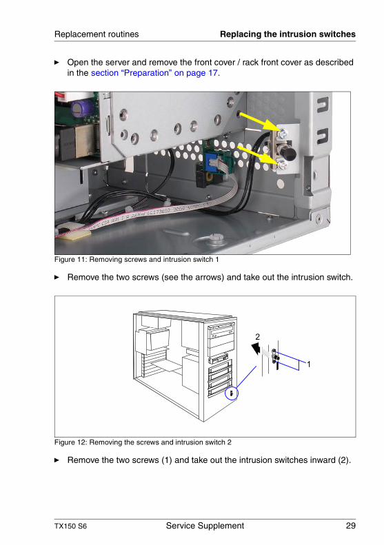
Ê Open the server and remove the front cover / rack front cover as described in the section “Preparation” on page 17.
Figure 11: Removing screws and intrusion switch 1
Ê Remove the two screws (see the arrows) and take out the intrusion switch.
Figure 12: Removing the screws and intrusion switch 2
Ê Remove the two screws (1) and take out the intrusion switches inward (2).
2
1
30 Service Supplement TX150 S6
Replacing the processor Replacement routines
Ê Pull the first removed intrusion switch out of the cable clamp.
V CAUTION!
Note the cable routing.
Ê Remove the intrusion switch cable from the connector on the system board (see also the Technical Manual of the system board).
Ê Plug the new intrusion switch cable to the connector on the system board.
Ê Route the intrusion switch cable.
Ê Position the intrusion switch with the three wires on the front cover and fasten it with two screws.
Ê Insert the intrusion switch with the two wires in its holder and fasten the switch with two screws.
Ê Close the server and connect all power plugs (for a detailed description see the Options Guide).
4.9 Replacing the processor
V CAUTION!
Processors are modules which can react extremely sensitively to electro-static discharges and which must therefore always be handled with care. After a processor has been removed from its protective sleeve or from its socket, place it with its smooth side down on a non-conducting, antistatic surface. Never push a processor over a surface.
Ê Open the server as described in the section “Preparation” on page 17.
TX150 S6 Service Supplement 31
Replacement routines Replacing the processor
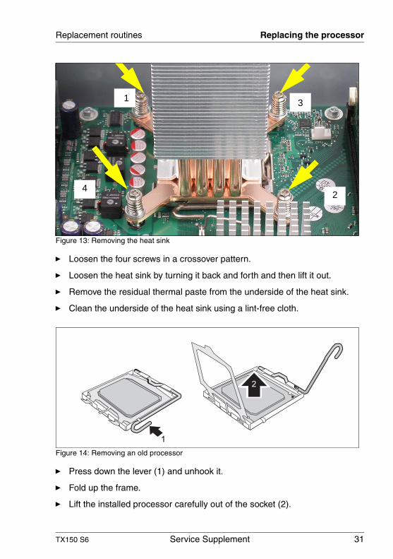
Figure 13: Removing the heat sink
Ê Loosen the four screws in a crossover pattern.
Ê Loosen the heat sink by turning it back and forth and then lift it out.
Ê Remove the residual thermal paste from the underside of the heat sink.
Ê Clean the underside of the heat sink using a lint-free cloth.
Figure 14: Removing an old processor
Ê Press down the lever (1) and unhook it.
Ê Fold up the frame.
Ê Lift the installed processor carefully out of the socket (2).
1
4
3
2
1
2

32 Service Supplement TX150 S6
Replacing the processor Replacement routines
Figure 15: Inserting a new processor
Ê Remove the protective cap from the bottom side of the new processor.
Ê Position the new processor over the socket and then carefully press it into the socket (1).
V CAUTION!
The processor can only be installed in one particular direction. Note the marking on one of the corners. To avoid damaging the pins or the processor, do not force it into the socket.
Figure 16: Fixing the processor
Ê Fold down the frame (1).
V CAUTION!
The processor holder must fall down by itself. Do not close with force, because soldering pads may be damaged.
Ê Press the lever slowly downward (2) until it is hooked in again (3).
a1
1 2
3
TX150 S6 Service Supplement 33
Replacement routines Replacing the processor
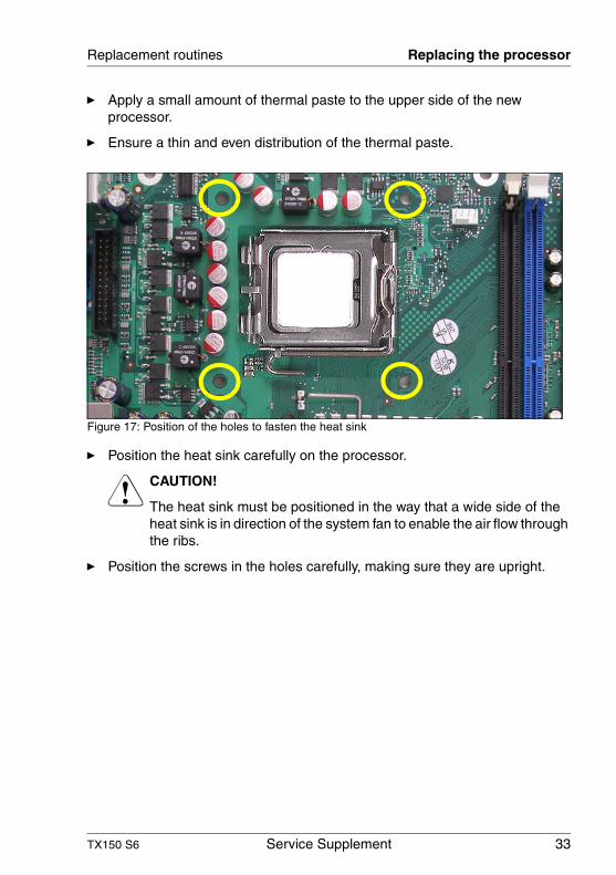
Ê Apply a small amount of thermal paste to the upper side of the new processor.
Ê Ensure a thin and even distribution of the thermal paste.
Figure 17: Position of the holes to fasten the heat sink
Ê Position the heat sink carefully on the processor.
V CAUTION!
The heat sink must be positioned in the way that a wide side of the heat sink is in direction of the system fan to enable the air flow through the ribs.
Ê Position the screws in the holes carefully, making sure they are upright.

34 Service Supplement TX150 S6
Replacing the processor Replacement routines
Figure 18: Mounting the heat sink
Ê Tighten the four screws crosswise. Follow the following steps:
1. Turn screw no.1 two/three turns, then will be no tension on the processor when tightening the next screws.
2. Tighten screws no. 2, 3 and 4 in this order.
3. Tighten screw no.1 finally.
Tighten all screws as far as they will go with a torque of 0.6 NM.
Ê Close the server and connect all power plugs (for a detailed description see the Options Guide).
I After replacing the processor, it is recommended to update the BIOS to ensure proper operation (BIOS flash diskette, for a description see the BIOS Manual).
1
4
3
2
TX150 S6 Service Supplement 35
Replacement routines Replacing the system board
4.10 Replacing the system board
I The system board is optional equipped with a TPM (Trusted Platform Module) by the manufacturer. This module enables programs from third party manufacturers to store key information (e.g. drive encryption using Windows Bitlocker Drive Encryption).
The TPM is activated via the BIOS system (for more information, refer to the Fujitsu Siemens Computers BIOS manual).
V CAUTION!
– Before replacing the system board, ask your customer if he is using the TPM functionality.
– If the customer is using the TPM functionality, advise him that he must provide you with the TPM backup copies. For security reasons, the TPM must be restored/re-saved by the customer.
If the customer DOES NOT have a backup copy, inform him that replacing the system board will cause him to lose all his data.
Ê Open the server as described in the section “Preparation” on page 17.
Ê Lay the server on a table with the uncovered side facing upward. Place the server in such a way that the feet can project over the edge.
Ê Remove all external cables.
Ê Remove all controllers from their slots (for a description see the Operating Manual and the Options Guide). Take note of the slots of the controllers and the cabling.
Ê Remove the system fan (for a description see the Options Guide).
Ê Remove the processor (see the section “Replacing the processor” on page 30).
Ê Remove the memory modules (for a description see the Options Guide).
Ê Remove all cables which may be connected to the system board.
36 Service Supplement TX150 S6
Replacing the system board Replacement routines
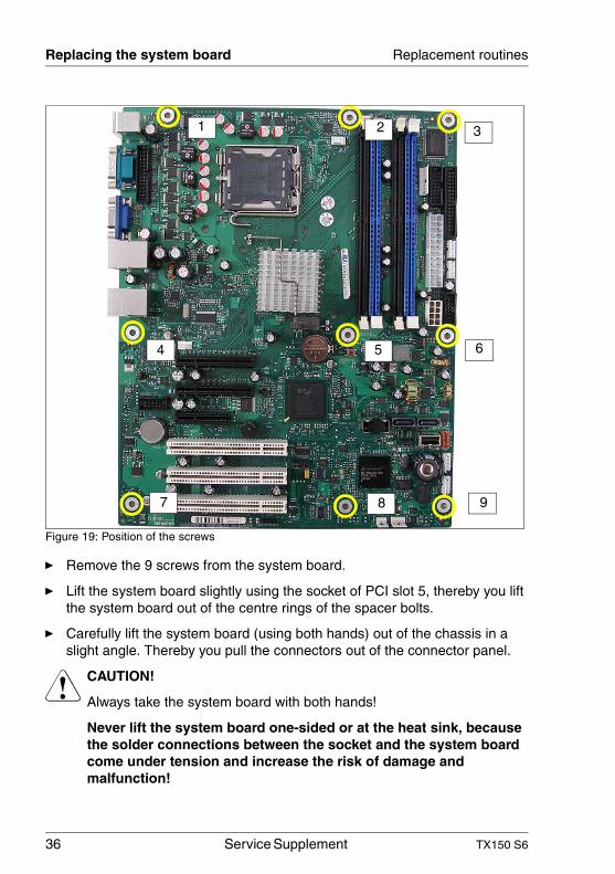
Figure 19: Position of the screws
Ê Remove the 9 screws from the system board.
Ê Lift the system board slightly using the socket of PCI slot 5, thereby you lift the system board out of the centre rings of the spacer bolts.
Ê Carefully lift the system board (using both hands) out of the chassis in a slight angle. Thereby you pull the connectors out of the connector panel.
V CAUTION!
Always take the system board with both hands!
Never lift the system board one-sided or at the heat sink, because the solder connections between the socket and the system board come under tension and increase the risk of damage and malfunction!
1 2 3
4 5 6
7 8 9
TX150 S6 Service Supplement 37
Replacement routines Replacing the system board
Don’t damage the EMI springs which are essential to comply with appli-cable EMC regulations and satisfy cooling requirements and fire protection measures.
Ê Place the removed and the new system board on an antistatic surface.
Ê Remove the protective plastic cover from the processor socket of the new system board and fit it onto the socket of the defective system board which will be sent back to spares.
I Returned system boards without this cover probably have to be scrapped.
Ê Check the settings on the new system board (for a description see the Technical Manual of the system board).
Ê Insert the system board by holding it at a slight angle. Slide the connectors into the connector panel.
Ê Lower the system board carefully into the chassis.
Ê Adjust the system board. If necessary adjust the position of the system board with a gentle twisting motion.
I When the system board is in the right position, the centre rings engage with the holes indicated. The centre rings are placed under the screw positions 1 and 5.
Ê Fasten the system board with the 9 screws.
Ê Reconnect the cables to their original connectors (see also the cabling plans in the Options Guide).
Ê Install the memory modules (for a description see the Options Guide).
Ê Install the processor and the heat sink (see the section “Replacing the processor” on page 30).
Ê Install the system fan (for a description see the Options Guide).
Ê Install all controllers in their former slots (for a description see the Operating Manual and Options Guide).
38 Service Supplement TX150 S6
Replacing the system board Replacement routines
Ê Close the server and connect all power plugs (for a detailed description see the Options Guide).
Ê Connect all external cables.
V CAUTION!
After installing the new system board, it is necessary to update the system specific data (BIOS, iRMC firmware, SDR (sensor data record) data) to ensure proper operation (BIOS flash diskette, for a description see the BIOS Manual).
TX150 S6 Service Supplement 39
5 Appendix
5.1 Board layout
I The board layout of the system board is described in the Technical Manual of the system board D2559.
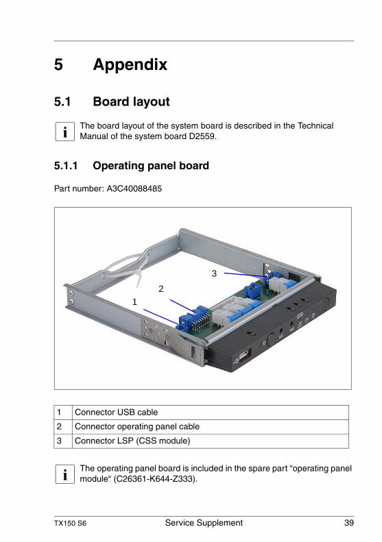
5.1.1 Operating panel board
Part number: A3C40088485
I The operating panel board is included in the spare part “operating panel module“ (C26361-K644-Z333).
1 Connector USB cable
2 Connector operating panel cable
3 Connector LSP (CSS module)
12
3
40 Service Supplement TX150 S6
Board layout Appendix
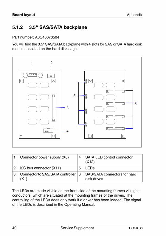
5.1.2 3.5“ SAS/SATA backplane
Part number: A3C40070504
You will find the 3.5“ SAS/SATA backplane with 4 slots for SAS or SATA hard disk modules located on the hard disk cage.
The LEDs are made visible on the front side of the mounting frames via light conductors, which are situated at the mounting frames of the drives. The controlling of the LEDs does only work if a driver has been loaded. The signal of the LEDs is described in the Operating Manual.
1 Connector power supply (X6) 4 SATA LED control connector (X12)
2 I2C bus connector (X11) 5 LEDs
3 Connector to SAS/SATA controller (X1)
6 SAS/SATA connectors for hard disk drives
1 2
3
4
5
6
TX150 S6 Service Supplement 41
Appendix Board layout
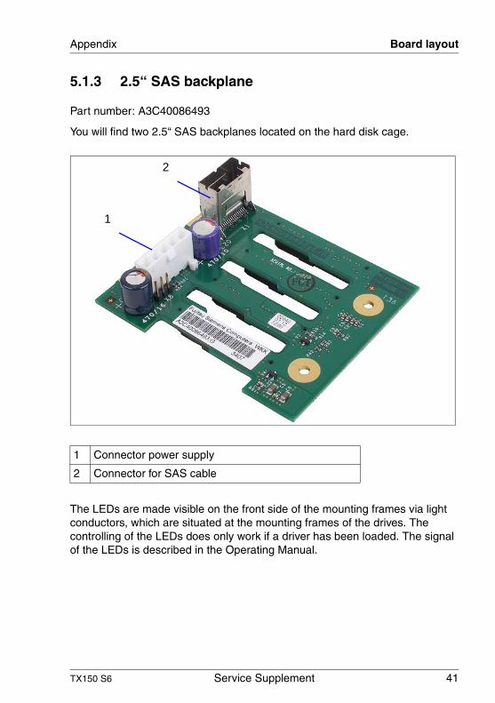
5.1.3 2.5“ SAS backplane
Part number: A3C40086493
You will find two 2.5“ SAS backplanes located on the hard disk cage.
The LEDs are made visible on the front side of the mounting frames via light conductors, which are situated at the mounting frames of the drives. The controlling of the LEDs does only work if a driver has been loaded. The signal of the LEDs is described in the Operating Manual.
1 Connector power supply
2 Connector for SAS cable
1
2
42 Service Supplement TX150 S6
Board layout Appendix
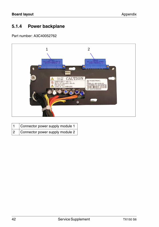
5.1.4 Power backplane
Part number: A3C40052762
1 Connector power supply module 1
2 Connector power supply module 2
1 2

TX150 S6 Service Supplement 43
Index
2.5“ SAS backplane 24, 413.5" SAS/SATA backplane 23, 40
EESD (devices sensitive to electrostatic
discharge) 15
IIDTEMP combo 26intrusion detection switches 28
Llaser information 15light emitting diode (LED) 15lithium battery 13
Mmeaning of the symbols 8
Nnotational conventions 8
Ooperating panel board 39operating panel module 19
PPower backplane 22, 42processor 30
Sstandard PS 20system board 35
Ttarget group 5

Information on this document On April 1, 2009, Fujitsu became the sole owner of Fujitsu Siemens Compu-ters. This new subsidiary of Fujitsu has been renamed Fujitsu Technology So-lutions.
This document from the document archive refers to a product version which was released a considerable time ago or which is no longer marketed.
Please note that all company references and copyrights in this document have been legally transferred to Fujitsu Technology Solutions.
Contact and support addresses will now be offered by Fujitsu Technology So-lutions and have the format …@ts.fujitsu.com.
The Internet pages of Fujitsu Technology Solutions are available at http://ts.fujitsu.com/... and the user documentation at http://manuals.ts.fujitsu.com.
Copyright Fujitsu Technology Solutions, 2009
Hinweise zum vorliegenden Dokument Zum 1. April 2009 ist Fujitsu Siemens Computers in den alleinigen Besitz von Fujitsu übergegangen. Diese neue Tochtergesellschaft von Fujitsu trägt seit-dem den Namen Fujitsu Technology Solutions.
Das vorliegende Dokument aus dem Dokumentenarchiv bezieht sich auf eine bereits vor längerer Zeit freigegebene oder nicht mehr im Vertrieb befindliche Produktversion.
Bitte beachten Sie, dass alle Firmenbezüge und Copyrights im vorliegenden Dokument rechtlich auf Fujitsu Technology Solutions übergegangen sind.
Kontakt- und Supportadressen werden nun von Fujitsu Technology Solutions angeboten und haben die Form …@ts.fujitsu.com.
Die Internetseiten von Fujitsu Technology Solutions finden Sie unter http://de.ts.fujitsu.com/..., und unter http://manuals.ts.fujitsu.com finden Sie die Benutzerdokumentation.
Copyright Fujitsu Technology Solutions, 2009