superior flow measurement accuracy - armstrong international · veris accelabar®...test data the...
TRANSCRIPT

VERIS ACCELABAR®
SUPERIOR FLOW MEASUREMENT ACCURACY
2North America • Latin America • India • Europe / Middle East / Africa • China • Pacific Rim
armstronginternational.com/veris
Designs, materials, weights and performance ratings are approximate and subject to change without notice. Visit armstronginternational.com/veris for up-to-date information.
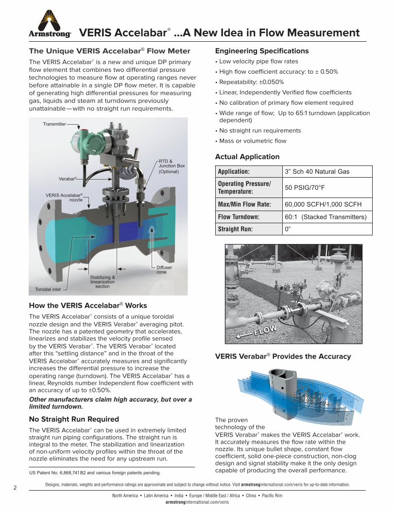
VERIS Accelabar® ...A New Idea in Flow MeasurementThe Unique VERIS Accelabar® Flow MeterThe VERIS Accelabar® is a new and unique DP primary flow element that combines two differential pressure technologies to measure flow at operating ranges never before attainable in a single DP flow meter. It is capable of generating high differential pressures for measuring gas, liquids and steam at turndowns previously unattainable—with no straight run requirements.
How the VERIS Accelabar® WorksThe VERIS Accelabar® consists of a unique toroidal nozzle design and the VERIS Verabar® averaging pitot. The nozzle has a patented geometry that accelerates, linearizes and stabilizes the velocity profile sensed by the VERIS Verabar®. The VERIS Verabar® located after this “settling distance” and in the throat of the VERIS Accelabar® accurately measures and significantly increases the differential pressure to increase the operating range (turndown). The VERIS Accelabar® has a linear, Reynolds number Independent flow coefficient with an accuracy of up to ±0.50%. Other manufacturers claim high accuracy, but over a limited turndown.
Engineering Specifications • Low velocity pipe flow rates
• High flow coefficient accuracy: to ± 0.50%
• Repeatability: ±0.050%
• Linear, Independently Verified flow coefficients
• No calibration of primary flow element required
• Wide range of flow; Up to 65:1 turndown (application dependent)
• No straight run requirements
• Mass or volumetric flow
No Straight Run RequiredThe VERIS Accelabar® can be used in extremely limited straight run piping configurations. The straight run is integral to the meter. The stabilization and linearization of non-uniform velocity profiles within the throat of the nozzle eliminates the need for any upstream run.
Actual Application
Application: 3” Sch 40 Natural Gas
Operating Pressure/ Temperature: 50 PSIG/70°F
Max/Min Flow Rate: 60,000 SCFH/1,000 SCFH
Flow Turndown: 60:1 (Stacked Transmitters)
Straight Run: 0”
US Patent No. 6,868,741 B2 and various foreign patents pending.
VERIS Verabar® Provides the Accuracy
The proventechnology of theVERIS Verabar® makes the VERIS Accelabar® work.It accurately measures the flow rate within the nozzle. Its unique bullet shape, constant flow coefficient, solid one-piece construction, non-clog design and signal stability make it the only design capable of producing the overall performance.
RTD & Junction Box(Optional)
Diffuser cone
Toroidal inlet
Stabilizing & linearization
section
VERIS Accelabar® nozzle
Verabar®
Transmitter

3North America • Latin America • India • Europe / Middle East / Africa • China • Pacific Rim
armstronginternational.com/veris
Designs, materials, weights and performance ratings are approximate and subject to change without notice. Visit armstronginternational.com/veris for up-to-date information.
VERIS Accelabar® ...Performance CharacteristicsComparative Analysis vs. Other Flow MetersThe VERIS Accelabar® fills the need not presently being filled by other flow meters for applications that:
• Do not have sufficient velocity to produce a readable signal or sufficient turndown
• Require the highest accuracy over an extended range
• Have little or no straight run piping before the meter
The VERIS Accelabar® performance characteristics far exceed those of other DP primary elements, vortex meters and many other types of flow meters.
These charts show the actual performance characteristics of the VERIS Accelabar® versus other flow meters based on the following flow conditions:
Flow TurndownMaximum & Minimum
VERIS Accelabar®
Orifice Plate
Cone Type
Averaging Pitot0 25 50 75
4
25
10
65
Max. Flow / Min. Flow
Minimum Straight Run RequirementsVERIS Accelabar®
Vortex
Orifice Plate
Cone Type
Averaging Pitot0 10 20 30
20
3
7
0
30
Equivalent Pipe Diameters
Permanent Pressure LossVERIS Accelabar®
Orifice Plate
Cone Type
0 25 50 75
75
60
35
% Permanent Pressure Loss
4North America • Latin America • India • Europe / Middle East / Africa • China • Pacific Rim
armstronginternational.com/veris
Designs, materials, weights and performance ratings are approximate and subject to change without notice. Visit armstronginternational.com/veris for up-to-date information.
VERIS Accelabar® ...Test Data
The Proof Is In The Data Many flow meters claim high accuracy and rangeability or turndown. However, few manufacturers define their limitations and even fewer can support it with actual test data. The tests below show the performance capabilities of the VERIS Accelabar®.
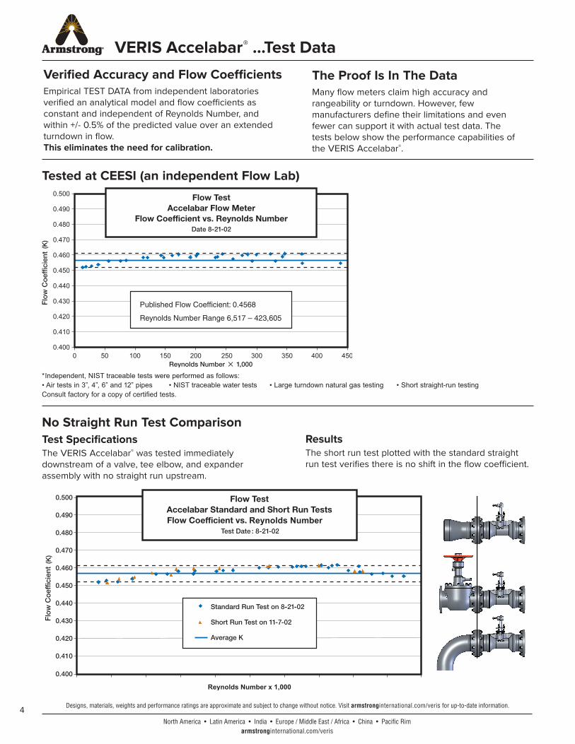
Tested at CEESI (an independent Flow Lab)
No Straight Run Test ComparisonTest SpecificationsThe VERIS Accelabar® was tested immediately downstream of a valve, tee elbow, and expander assembly with no straight run upstream.
ResultsThe short run test plotted with the standard straight run test verifies there is no shift in the flow coefficient.
Verified Accuracy and Flow CoefficientsEmpirical TEST DATA from independent laboratories verified an analytical model and flow coefficients as constant and independent of Reynolds Number, and within +/- 0.5% of the predicted value over an extended turndown in flow.This eliminates the need for calibration.
* Independent, NIST traceable tests were performed as follows:• Air tests in 3”, 4”, 6” and 12” pipes • NIST traceable water tests • Large turndown natural gas testing • Short straight-run testingConsult factory for a copy of certified tests.

5North America • Latin America • India • Europe / Middle East / Africa • China • Pacific Rim
armstronginternational.com/veris
Designs, materials, weights and performance ratings are approximate and subject to change without notice. Visit armstronginternational.com/veris for up-to-date information.
VERIS Accelabar® 1 – 12 Inch
The VERIS Accelabar® combined with a DP transmitter is a complete flow meter ready to install. It may be used with single or dual transmitters depending on the turndown and accuracy requirements.
An optional RTD is available in a welded thermowell assembly for dynamic, real-time density compensation (required for use with multi-variable transmitter's in certain applications).
AF Flanged Model
VERIS Accelabar® Model Selection 1. Furnish your flowing conditions. A flow calculation is
required to determine the DP and verification of the operating limits.
• Each meter size has a standard beta ratio sized for the optimal operating range.
• The maximum operating limits are determined by the VERIS Veracalc® flow sizing software.
2. If your flowing conditions exceed or limit selection of the body size that matches the pipe size, a larger or smaller Accelabar® body can be selected for optimal operating results...
Chart A
SpecificationsSensor Body Flange Accuracy Repeatability
316SS C8FM 304SS to ± 0.50% ± 0.050%
Meter Size Verabar® Sensor
Face-to-Face “FF”
Class 150# Class 300# Class 600# PN10 PN16 PN40 PN63 PN100
1” (DN25) -03 7.50” (190.5mm)
8.25” (209.6mm)
8.75” (222.3mm) N/A N/A 10.15”
(257.8mm) N/A 11.57” (293.5mm)
2” (DN50) -05 8.75” (222.3mm)
9.38” (238.3mm)
10.13” (257.3mm)
11.54” (293.2mm)
11.54” (293.2mm)
11.78” (299.2mm)
12.88” (327.2mm)
13.35” (339.2mm)
3” (DN80) -05 13.78” (350.0mm)
14.53” (369.1mm)
15.28” (388.1mm)
12.31” (312.8mm)
12.31” (312.8mm)
12.94” (328.8mm)
14.04” (356.8mm)
14.52” (368.8mm)
4” (DN100) -05 15.15” (384.8mm)
15.90” (403.9mm)
17.65” (448.3mm)
13.34” (338.9mm)
13.34” (338.9mm)
14.36” (364.9mm)
15.39” (390.9mm)
16.34” (414.9mm)
6” (DN150) -10 19.15” (486.4mm)
19.90” (505.5mm)
21.90” (556.3mm)
16.58” (421.1mm)
16.58” (421.1mm)
18.15” (461.1mm)
19.73” (501.1mm)
21.30” (541.1mm)
8” (DN200) -10 21.40” (543.6mm)
22.15” (562.6mm)
24.40” (619.8mm)
18.38” (466.9mm)
18.38” (466.9mm)
20.42” (518.9mm)
22.16” (562.9mm)
23.74” (602.9mm)
10” (DN250) -10 23.15”
(588.0mm)24.40”
(619.8mm)27.65”
(702.31mm)20.60”
(523.3mm)20.76”
(527.3mm)23.51”
(597.3mm)25.09”
(637.3mm)27.61”
(701.3mm)
12” (DN300) -10 26.22”
(666.0mm)27.47”
(697.7mm)29.97”
(761.9mm)22.62”
(574.6mm)23.41”
(594.6mm)26.32”
(668.6mm)28.29”
(718.6mm)30.65”
(778.6mm)
Transmitter
Weld Neck RF Flange
VERIS Accelabar® Flow Meter
Manifold Head
VERIS Verabar®
Retaining Plate
Packing Follower
"FF"
Graphite Packing
RTD Thermowell
Ready to Install
*Nominal Face-to-Face dimensions nominal. Custom lengths available.
6
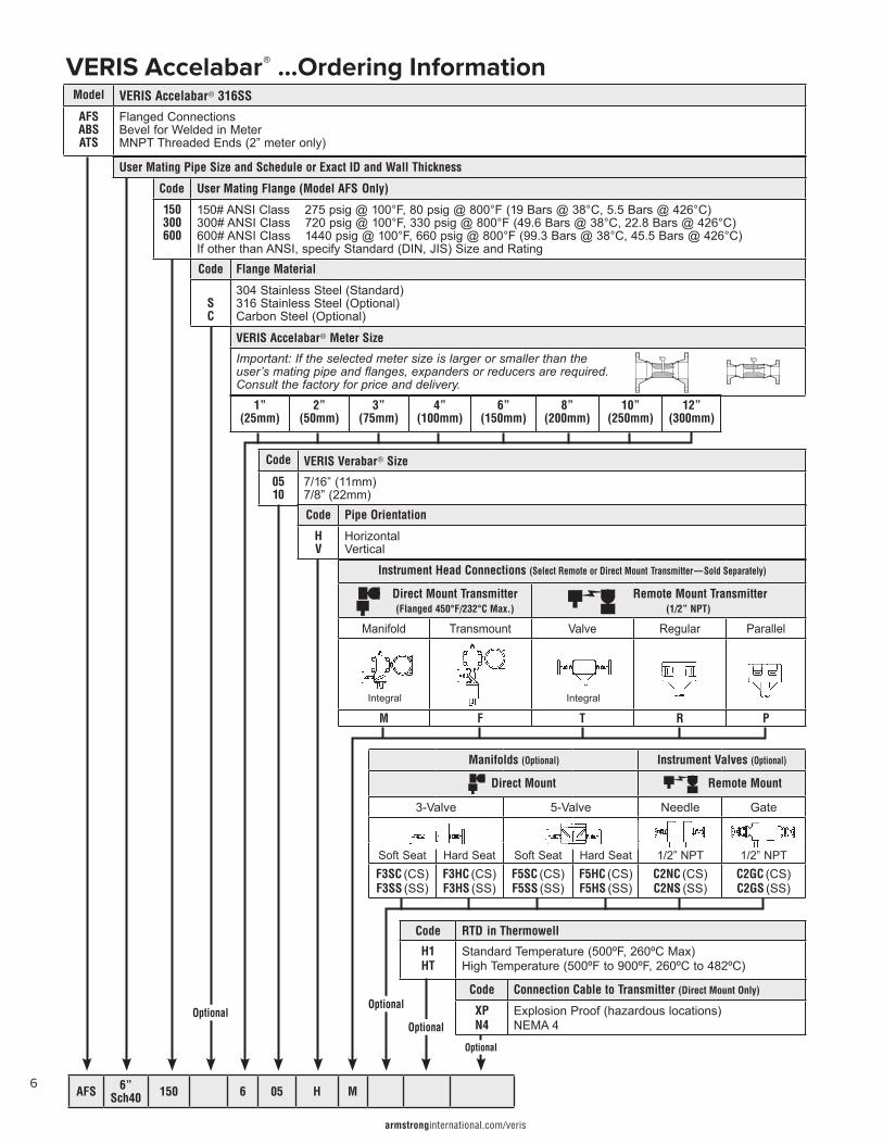
VERIS Accelabar® ...Ordering InformationModel VERIS Accelabar® 316SS
AFSABSATS
Flanged ConnectionsBevel for Welded in MeterMNPT Threaded Ends (2” meter only)
User Mating Pipe Size and Schedule or Exact ID and Wall Thickness
Code User Mating Flange (Model AFS Only)
150300600
150# ANSI Class 275 psig @ 100°F, 80 psig @ 800°F (19 Bars @ 38°C, 5.5 Bars @ 426°C)300# ANSI Class 720 psig @ 100°F, 330 psig @ 800°F (49.6 Bars @ 38°C, 22.8 Bars @ 426°C)600# ANSI Class 1440 psig @ 100°F, 660 psig @ 800°F (99.3 Bars @ 38°C, 45.5 Bars @ 426°C)If other than ANSI, specify Standard (DIN, JIS) Size and RatingCode Flange Material
SC
304 Stainless Steel (Standard)316 Stainless Steel (Optional)Carbon Steel (Optional)
VERIS Accelabar® Meter Size
Important: If the selected meter size is larger or smaller than the user’s mating pipe and flanges, expanders or reducers are required. Consult the factory for price and delivery.
Code VERIS Verabar® Size
0510
7/16” (11mm) 7/8” (22mm)Code Pipe Orientation
HV
HorizontalVertical
Instrument Head Connections (Select Remote or Direct Mount Transmitter—Sold Separately)
Direct Mount Transmitter(Flanged 450°F/232°C Max.)
Remote Mount Transmitter(1/2” NPT)
Manifold Transmount Valve Regular Parallel
M F T R P
Integral Integral
Manifolds (Optional) Instrument Valves (Optional)
Direct Mount Remote Mount
3-Valve 5-Valve Needle Gate
1/2” NPT 1/2” NPTSoft Seat Hard Seat Soft Seat Hard SeatF3SC (CS)F3SS (SS)
F3HC (CS)F3HS (SS)
F5SC (CS)F5SS (SS)
F5HC (CS)F5HS (SS)
C2NC (CS)C2NS (SS)
C2GC (CS)C2GS (SS)
OptionalOptional
Optional
Optional
Code RTD in Thermowell
H1HT
Standard Temperature (500ºF, 260ºC Max)High Temperature (500ºF to 900ºF, 260ºC to 482ºC)
Code Connection Cable to Transmitter (Direct Mount Only)
XPN4
Explosion Proof (hazardous locations)NEMA 4
AFS 6”Sch40 150 6 05 H M
1”(25mm)
2”(50mm)
3”(75mm)
4”(100mm)
6”(150mm)
8”(200mm)
10”(250mm)
12”(300mm)
armstronginternational.com/veris
7North America • Latin America • India • Europe / Middle East / Africa • China • Pacific Rim
armstronginternational.com/veris
Designs, materials, weights and performance ratings are approximate and subject to change without notice. Visit armstronginternational.com/veris for up-to-date information.
VERIS Accelabar®
...True Performance in Flow Measurement
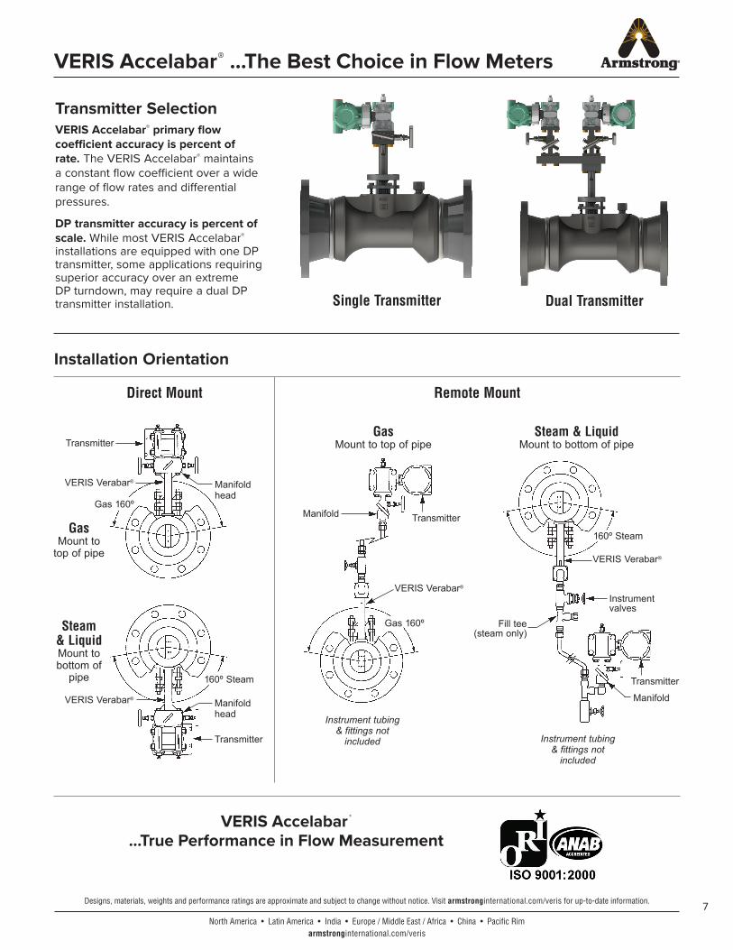
Installation Orientation
Direct Mount Remote Mount
Transmitter
Transmitter
VERIS Verabar®
GasMount to
top of pipe
Steam & LiquidMount to bottom of
pipe
Steam & LiquidMount to bottom of pipe
Transmitter
Manifold
Fill tee (steam only)
Instrument valves
Manifold head
VERIS Verabar®
Manifold head
160º Steam
160º Steam
Gas 160º
GasMount to top of pipe
Instrument tubing & fittings not
included
TransmitterManifold
Gas 160º
Transmitter SelectionVERIS Accelabar® primary flow coefficient accuracy is percent of rate. The VERIS Accelabar® maintains a constant flow coefficient over a wide range of flow rates and differential pressures.
DP transmitter accuracy is percent of scale. While most VERIS Accelabar® installations are equipped with one DP transmitter, some applications requiring superior accuracy over an extreme DP turndown, may require a dual DP transmitter installation.
Instrument tubing & fittings not
included
Single Transmitter Dual Transmitter
VERIS Accelabar® ...The Best Choice in Flow Meters
VERIS Verabar®
VERIS Verabar®

© 2020 Armstrong International, Inc. 479-EN V2.4
INTELLIGENT SOLUTIONS IN STEAM, AIR, AND HOT WATER
Armstrong InternationalNorth America • Latin America • India • Europe / Middle East / Africa • China • Pacific Rim
armstronginternational.com