experience in motion technical bulletin - imaha · experience in motion technical bulletin valbart...
TRANSCRIPT
Experience In MotionExperience in Motion
Experience in Motion
TECHNICAL BULLETINValbart TMCBV Trunnion-Mounted Control Ball ValveFCD VLENTB0068-02 11/10
Valbart TMCBV FCD VLENTB0068-02 11/10
2
Experience in Motion
High range of control with superior flow capacity for severe service applications in a smaller footprint.The TMCBV leverages technology from the leaders of trunnion-mounted ball valves and control valves for severe service applications. The TMCBV is available in the widest range of sizes and pressure ratings, thanks to its lower operating torques even at very high pressures.
As a result of its inherent higher rangeability combined with its increased flow capacity, the TMCBV can be smaller in size and dimensional envelope for a given process condition, thus becoming the most economical solu-tion when compared with traditional control valve offerings.
Metal-seated TMCBV has tungsten carbide coating on ball and seat, which enhances the life of the valve by ensuring class IV or Class V tight shut-off even after prolonged usage in service.
Carefully designed rotary seals, precision machining, and accurate trunnion guiding, all contribute to zero external leakage ensuring that the TMCBV meets all environmental standards.
The TMCBV has exclusive trims designed for liquid and gas applications based on field-proven technologies such as MegaStream, CavControl, ChannelStream, etc. to ensure that no compromize is made when dealing with unique challenges associated with cavitation control and noise attenuation.
Operated by a heavy-duty pneumatic/hydraulic double-acting or spring -return actuator through a high-performance Logix digital positioner, the TMCBV maintains high positioning accuracy, repeatability, controlled high speed and reliable response. With the advanced diagnostic solutions which can be seamlessly integrated into a host control and/or plant asset management system, the TMCBV is the most economical integrated control valve with state-of-the-art features and performance.
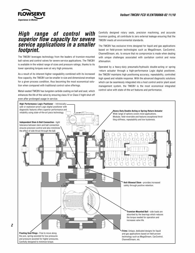
High Performance Logix Positioner - Intrinsically-safe or explosion-proof Logix digital positioner with diagnostic features offers superior performance and reliability using state-of-the-art piezo technology.
Independent Stem & Ball Connection - tight tolerance between stem and ball connection ensures precision control and also minimizes the effect of side thrust through the ball.
Floating Seat Rings - Free to move along the axis, spring-assisted for low pressures and pressure-assisted for higher pressures. Carefully designed to minimize torque.
Trims: Unique, dedicated designs for liquid and gas applications based on field-proven technology such as MegaStream, CavControl, ChannelStream, etc.
Heavy-Duty Double-Acting or Spring-Return Actuator Wide range of options covers most applications. Modular, field-reversible and features exceptional throt-tling stiffness, repeatability and low hysteresis.
Anti-Blowout Stem - provides increased safety through positive retention.
Trunnion-Mounted Ball - side loads are absorbed by the bearings which reduces the torque needed for operation and increases valve life.

3
Valbart TMCBV FCD VLENTB0068-02 11/10
flowserve.com
Experience in Motion
TMCBV Advantages & Features
Features Advantages
Wide range of trim designs based on industry-proven technologies such as MegaStream, CavControl, ChannelStream, Z-trim etc. Trims can be custom-engineered for unique applications.
Effective cavitation control and noise attenuation in the most demanding applications
Metal to Metal, tungsten carbide-coated seats can provide ANSI class IV and Class V shut-off up to class 2500
Soft seats can achieve class VI shutoff.
Tight Shut-off even after prolonged usage
Compact DesignHigher flow capacity for a given size results in a smaller size valve and actuator, thus leading to significant space, weight and cost savings.
Very high rangeability in excess of 300:1 Wide range of control
Accurate machining of stem and bonnet sealing surfaces ensures compliance with the most severe pollution control regulations.
Low emission stem seals
Geometry allows easier overlay of special alloys on wetted parts including body, seat, ball and seat pockets.
Lower cost on corrosive/erosive applications
Fewer moving parts Higher level of reliability and performance at a lower cost
Very tight tolerances maintained in stem-to-ball and stem-to-actuator connections.
Precise Control
Actuator has Quad seals and wear rings on piston and also a precisely machined guide bar to withstand lateral loads.
Higher cycle life
Logix digital positioners are equipped with advanced diagnostics features which can be seamlessly integrated into a host control and/or plant asset management program, thus allowing for predic-tive and preventive maintenance.
Lower cost of maintenance and decreased downtime
QUICK-CAL™ button, DIP switches, Jog buttons and variable gain selector allow setup and calibration in minutes.
Shorter commissioning times and costs
Product Range and Specifications
Size & Class
6” thru 56” Class 150, 300, 600
6” thru 48” Class 900, 1500
6” thru 24” Class 2500
Design Standard API 6D
Body Design Side-Entry, Top-Entry, Welded
Body Style Full Port, Reduced Port
End Connection Integral Flange, Butt Weld
Face-to-Face API 6D/ASME B16.10
Flange Facing Raised Face, RTJ
Bonnet Type Standard, Extended, Cryogenic
Overlay Options
Seat Pocket & Stem Seal
All Seal Areas
All Wetted Parts
Fire safe Certification
API 6FA, API 607, BS 6755 Part 2
Actuator TypeDouble-acting Pneumatic/Hydraulic cylinder, Fail-safe Spring-return, or Electric Modulating
Manual OverridesJack screw, Bevel gear, De-clutchable worm gear, hydraulic
Fail Safe Action Fail-to-open or Fail-to-close (field reversible)
PositionerIntrinsically-safe, Explosion-proofHART, Foundation Fieldbus(for detailed positioner specification see page 23)
Deadband <0.1% full scale
Repeatability <0.05% full scale
Linearity <0.5% (rotary), <0.8%, (sliding stem) full scale

Valbart TMCBV FCD VLENTB0068-02 11/10
4
Experience in Motion
Typical Construction & Materials
Body & Bonnet
A 350 Gr. LF 2
A 105
A 182 Gr. F316/316L
A 182 Gr. F51 (Duplex)
A 182 Gr. F53 (Super-Duplex)
A 182 Gr. F44 (Super-Austenitic)
Inconel 625
Other
Body Overlay
Material
316L SS
Inconel 625
Seals
Viton GLT/AED
HNBR
Viton AED
Lip Seal (PTFE-Elgiloy)
Graphite
Bearings
CS + PTFE
316 SS + PTFE
Inconel + PTFE
Inconel (HT)
Body Bolting
B7/2H
L7/7
B8/8
B7M/2HM
L7M/7M
B8M/8M
Ball & Seat Ring
A 182 Gr. F316
A 182 Gr. F316LN
A 182 Gr. F51
A 182 Gr. F53
Inconel 625
A 350 Gr. LF2 + 316SS Overlay
A 350 Gr. LF2 + Inconel Overlay
Ball CoatingTungsten Carbide Coating (TCC)
Chromium Carbide Coating (CCC)
Soft Seat
Nylon 6 MoS2
Nylon PA-12
Devlon V-API
PEEK
RPTFE
Stem
Material
17-4PH
XM-19 (Nitronic 50)
A 182 Gr. F51
A 182 Gr. F53
Inconel 718
Actuator
Cylinder: Hard-chrome-plated Carbon
Steel
Body: Ductile iron/Low temp CS
Piston: Ductile Iron
Piston rod: Alloy steel
Seals: Nitrile/Viton/Fluorosilicone
Spring: Alloy steel
Positioner
Housing: Powder-painted die-cast
Aluminum/ Stainless steel
Soft goods: Nitrile/Viton/
Fluorosilicone
5
Valbart TMCBV FCD VLENTB0068-02 11/10
flowserve.com
Experience in Motion
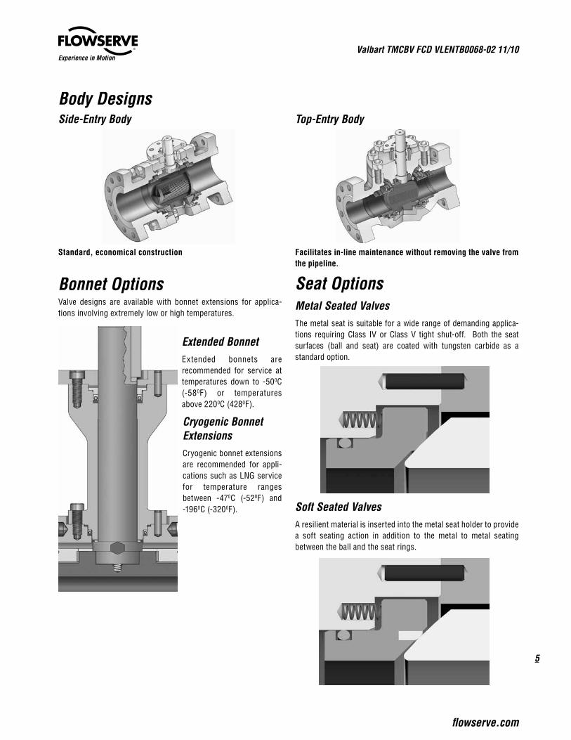
Body Designs
Metal Seated ValvesThe metal seat is suitable for a wide range of demanding applica-tions requiring Class IV or Class V tight shut-off. Both the seat surfaces (ball and seat) are coated with tungsten carbide as a standard option.
Soft Seated ValvesA resilient material is inserted into the metal seat holder to provide a soft seating action in addition to the metal to metal seating between the ball and the seat rings.
Extended BonnetExtended bonnets are recommended for service at temperatures down to -500C (-580F) or temperatures above 2200C (4280F).
Side-Entry Body
Standard, economical construction
Top-Entry Body
Facilitates in-line maintenance without removing the valve from the pipeline.
Bonnet OptionsValve designs are available with bonnet extensions for applica-tions involving extremely low or high temperatures.
Cryogenic Bonnet ExtensionsCryogenic bonnet extensions are recommended for appli-cations such as LNG service for temperature ranges between -470C (-520F) and -1960C (-3200F).
Seat Options
Valbart TMCBV FCD VLENTB0068-02 11/10
6
Experience in Motion
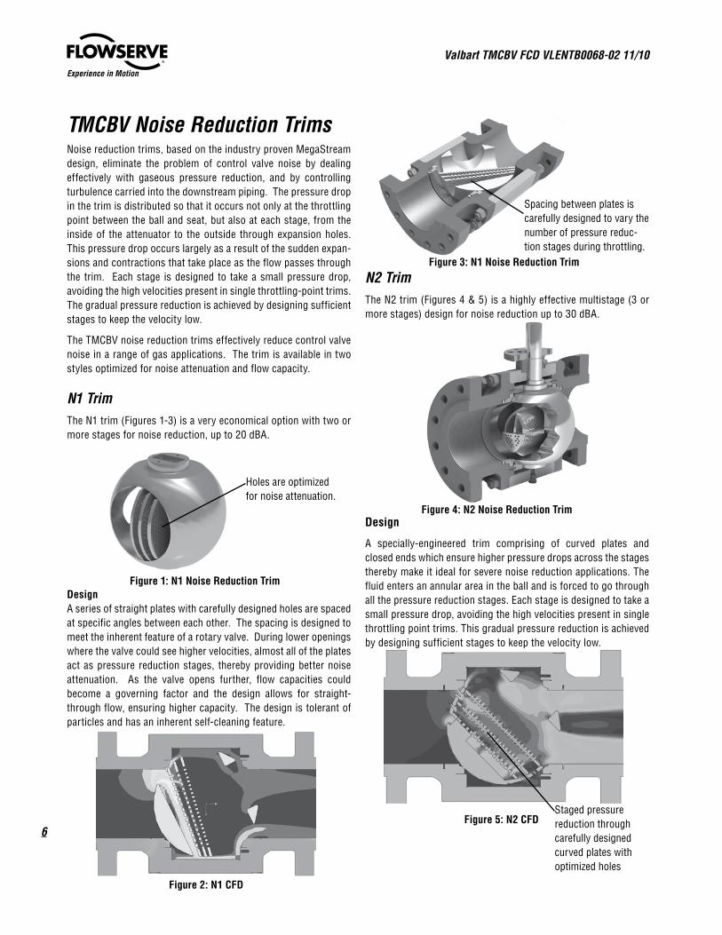
TMCBV Noise Reduction TrimsNoise reduction trims, based on the industry proven MegaStream design, eliminate the problem of control valve noise by dealing effectively with gaseous pressure reduction, and by controlling turbulence carried into the downstream piping. The pressure drop in the trim is distributed so that it occurs not only at the throttling point between the ball and seat, but also at each stage, from the inside of the attenuator to the outside through expansion holes. This pressure drop occurs largely as a result of the sudden expan-sions and contractions that take place as the flow passes through the trim. Each stage is designed to take a small pressure drop, avoiding the high velocities present in single throttling-point trims. The gradual pressure reduction is achieved by designing sufficient stages to keep the velocity low.
The TMCBV noise reduction trims effectively reduce control valve noise in a range of gas applications. The trim is available in two styles optimized for noise attenuation and flow capacity.
N1 TrimThe N1 trim (Figures 1-3) is a very economical option with two or more stages for noise reduction, up to 20 dBA.
DesignA series of straight plates with carefully designed holes are spaced at specific angles between each other. The spacing is designed to meet the inherent feature of a rotary valve. During lower openings where the valve could see higher velocities, almost all of the plates act as pressure reduction stages, thereby providing better noise attenuation. As the valve opens further, flow capacities could become a governing factor and the design allows for straight-through flow, ensuring higher capacity. The design is tolerant of particles and has an inherent self-cleaning feature.
N2 TrimThe N2 trim (Figures 4 & 5) is a highly effective multistage (3 or more stages) design for noise reduction up to 30 dBA.
Design
A specially-engineered trim comprising of curved plates and closed ends which ensure higher pressure drops across the stages thereby make it ideal for severe noise reduction applications. The fluid enters an annular area in the ball and is forced to go through all the pressure reduction stages. Each stage is designed to take a small pressure drop, avoiding the high velocities present in single throttling point trims. This gradual pressure reduction is achieved by designing sufficient stages to keep the velocity low.
Figure 1: N1 Noise Reduction Trim
Holes are optimized for noise attenuation.
Figure 3: N1 Noise Reduction Trim
Spacing between plates is carefully designed to vary the number of pressure reduc-tion stages during throttling.
Figure 2: N1 CFD
Staged pressure reduction through carefully designed curved plates with optimized holes
Figure 5: N2 CFD
Figure 4: N2 Noise Reduction Trim
7
Valbart TMCBV FCD VLENTB0068-02 11/10
flowserve.com
Experience in Motion
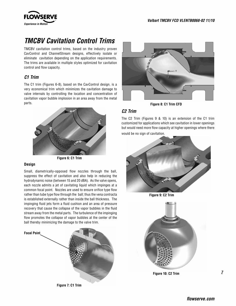
TMCBV Cavitation Control TrimsTMCBV cavitation control trims, based on the industry proven CavControl and ChannelStream designs, effectively isolate or eliminate cavitation depending on the application requirements. The trims are available in multiple styles optimized for cavitation control and flow capacity.
C1 TrimThe C1 trim (Figures 6-8), based on the CavControl design, is a very economical trim which minimizes the cavitation damage to valve internals by controlling the location and concentration of cavitation vapor bubble implosion in an area away from the metal parts.
Design
Small, diametrically-opposed flow nozzles through the ball, suppress the effect of cavitation and also help in reducing the hydrodynamic noise (between 15 and 20 dBA). As the valve opens, each nozzle admits a jet of cavitating liquid which impinges at a common focal point. Nozzles are used to ensure orifice type flow rather than tube type flow through the ball; thus the vena contracta is established externally rather than inside the ball thickness. The impinging fluid jets form a fluid cushion and an area of pressure recovery that cause the collapse of the vapor bubbles in the fluid stream away from the metal parts. The turbulence of the impinging flow promotes the collapse of vapor bubbles at the center of the ball thereby minimizing the damage to the valve trim.
C2 TrimThe C2 Trim (Figures 9 & 10) is an extension of the C1 trim customized for applications which see cavitation in lower openings but would need more flow capacity at higher openings where there
would be no sign of cavitation.
Figure 6: C1 Trim
Focal Point
Figure 9: C2 Trim
Figure 8: C1 Trim CFD
Figure 7: C1 Trim
Figure 10: C2 Trim

Valbart TMCBV FCD VLENTB0068-02 11/10
8
Experience in Motion
C3 TrimThe C3 Trim (Figures 11 & 12), based on the ChannelStream design, is a highly-effective multistage cavitation control design which prevents cavitation from forming and minimizes hydrody-namic noise even under the most severe applications. This unique design not only eliminates cavitation damage, but also provides easy maintenance and long life, even when installed in the most difficult applications.
Design
The cartridge has a series of plates with drilled holes and channels. Rather than acting as a flow restriction, the drilled holes in the cartridge are used as expansion areas for the fluid as it enters from restrictive channels machined in each stage of the cartridge. Successive intersections of the restrictive channels result in additional pressure losses, while expansion holes connected to the channel create a series of expansions and contractions that result in a series of pressure drops. This staged pressure drop eliminates cavitation in many applications and minimizes the energy of cavitation that my still occur in others.
Depending on the applications, C3 can be custom engineered to control severe cavitation associated with higher pressure drops at lower openings, while providing the upper-end flow capacity which
could be the governing factor at higher openings.
Z-TrimsZ-Trims combine the benefits of an advanced control valve with the simplicity of a ball valve. Most effective with low to medium pressure drops, the Z-trims (Figures 13-15) excel at eliminating noise in high flow services.
Standard TrimStandard trim for the Trunnion-Mounted Control Ball valve is a simple full port as shown below.
The Z-Trims are omnidirectional and self-cleaning. Z1 trim may reduce noise by 17 dB. Z2 trim may give 23 dB. Both are also useful for preventing cavitation at low pressure ratios. The inclined plates give smooth transition as the valve travels, without stair-stepping in the characteristic curve.
Figure 14: Z2 TrimFigure 13: Z1 Trim
Figure 15: Z2 Trim (shown on a reduced port valve)
Figure 11: C3 Trim
Figure 12: C3 Trim CFD
Figure 16: TMCBV with Standard Trim
9
Valbart TMCBV FCD VLENTB0068-02 11/10
flowserve.com
Experience in Motion
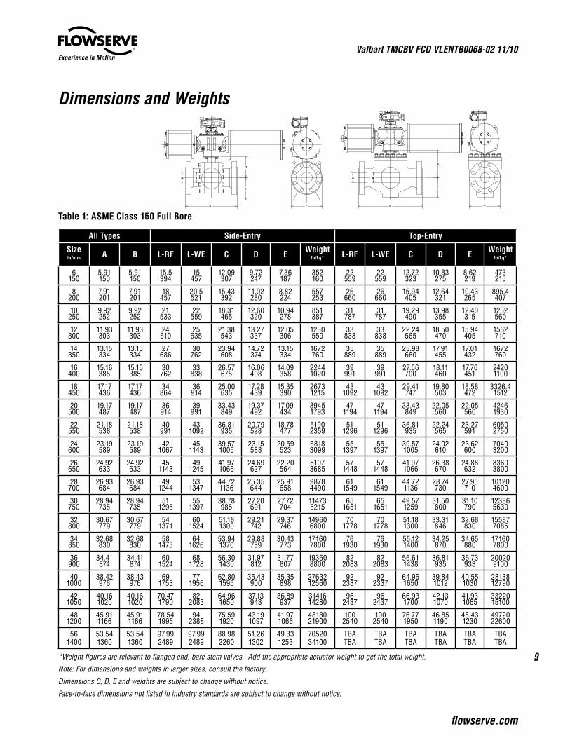
Dimensions and Weights
Table 1: ASME Class 150 Full Bore
All Types Side-Entry Top-Entry
Sizein/mm A B L-RF L-WE C D E Weight
lb/kg* L-RF L-WE C D E Weightlb/kg*
6150
5.91150
5.91150
15.5394
15457
12.09307
9.72247
7.36187
352160
22559
22559
12.72323
10.83275
8.62219
473215
8200
7.91201
7.91201
18457
20.5521
15.43392
11.02280
8.82224
557253
26660
26660
15.94405
12.64321
10.43265
895.4407
10250
9.92252
9.92252
21533
22559
18.31465
12.60320
10.94278
851387
31787
31787
19.29490
13.98355
12.40315
1232560
12300
11.93303
11.93303
24610
25635
21.38543
13.27337
12.05306
1230559
33838
33838
22.24565
18.50470
15.94405
1562710
14350
13.15334
13.15334
27686
30762
23.94608
14.72374
13.15334
1672760
35889
35889
25.98660
17.91455
17.01432
1672760
16400
15.16385
15.16385
30762
33838
26.57675
16.06408
14.09358
22441020
39991
39991
27.56700
18.11460
17.76451
24201100
18450
17.17436
17.17436
34864
36914
25.00635
17.28439
15.35390
26731215
431092
431092
29.41747
19.80503
18.58472
3326.41512
20500
19.17487
19.17487
36914
39991
33.43849
19.37492
17.09434
39451793
471194
471194
33.43849
22.05560
22.05560
42461930
22550
21.18538
21.18538
40991
431092
36.81935
20.79528
18.78477
51902359
511296
511296
36.81935
22.24565
23.27591
60502750
24600
23.19589
23.19589
421067
451143
39.571005
23.15588
20.59523
68183099
551397
551397
39.571005
24.02610
23.62600
70403200
26650
24.92633
24.92633
451143
491245
41.971066
24.69627
22.20564
81073685
571448
571448
41.971066
26.38670
24.88632
83603800
28700
26.93684
26.93684
491244
531347
44.721136
25.35644
25.91658
98784490
611549
611549
44.721136
28.74730
27.95710
101204600
30750
28.94735
28.94735
511295
551397
38.78985
27.20691
27.72704
114735215
651651
651651
49.571259
31.50800
31.10790
123865630
32800
30.67779
30.67779
541371
601524
51.181300
29.21742
29.37746
149606800
701778
701778
51.181300
33.31846
32.68830
155877085
34850
32.68830
32.68830
581473
641626
53.941370
29.88759
30.43773
171607800
761930
761930
55.121400
34.25870
34.65880
171607800
36900
34.41874
34.41874
601524
681728
56.301430
31.97812
31.77807
193608800
822083
822083
56.611438
36.81935
36.73933
200209100
401000
38.42976
38.43976
691753
771956
62.801595
35.43900
35.35898
2763212560
922337
922337
64.961650
39.841012
40.551030
2813812790
421050
40.161020
40.161020
70.471790
822083
64.961650
37.13943
36.89937
3141614280
962437
962437
66.931700
42.131070
41.931065
3322015100
481200
45.911166
45.911166
78.541995
942388
75.591920
43.191097
41.971066
4818021900
1002540
1002540
76.771950
46.851190
48.431230
4972022600
561400
53.541360
53.541360
97.992489
97.992489
88.982260
51.261302
49.331253
7052034100
TBATBA
TBATBA
TBATBA
TBATBA
TBATBA
TBATBA
*Weight figures are relevant to flanged end, bare stem valves. Add the appropriate actuator weight to get the total weight.
Note: For dimensions and weights in larger sizes, consult the factory.
Dimensions C, D, E and weights are subject to change without notice.
Face-to-face dimensions not listed in industry standards are subject to change without notice.
L
E
C
BA
D
E
D
L
BA
C
Valbart TMCBV FCD VLENTB0068-02 11/10
10
Experience in Motion
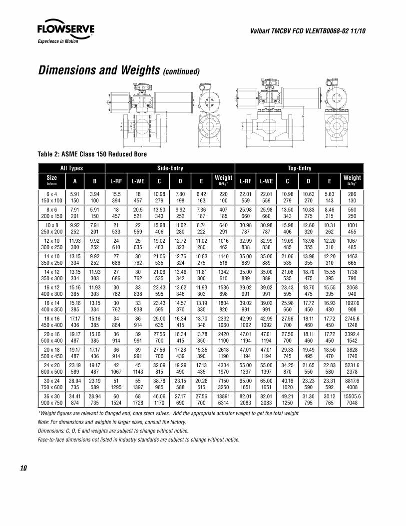
Dimensions and Weights (continued)
Table 2: ASME Class 150 Reduced Bore
All Types Side-Entry Top-Entry
Sizein/mm A B L-RF L-WE C D E Weight
lb/kg* L-RF L-WE C D E Weightlb/kg*
6 x 4150 x 100
5.91150
3.94100
15.5394
18457
10.98279
7.80198
6.42163
220100
22.01559
22.01559
10.98279
10.63270
5.63143
286130
8 x 6200 x 150
7.91201
5.91150
18457
20.5521
13.50343
9.92252
7.36187
407185
25.98660
25.98660
13.50343
10.83275
8.46215
550250
10 x 8250 x 200
9.92252
7.91201
21533
22559
15.98406
11.02280
8.74222
640291
30.98787
30.98787
15.98406
12.60320
10.31262
1001455
12 x 10300 x 250
11.93300
9.92252
24610
25635
19.02483
12.72323
11.02280
1016462
32.99838
32.99838
19.09485
13.98355
12.20310
1067485
14 x 10350 x 250
13.15334
9.92252
27686
30762
21.06535
12.76324
10.83275
1140518
35.00889
35.00889
21.06535
13.98355
12.20310
1463665
14 x 12350 x 300
13.15334
11.93303
27686
30762
21.06535
13.46342
11.81300
1342610
35.00889
35.00889
21.06535
18.70475
15.55395
1738790
16 x 12400 x 300
15.16385
11.93303
30762
33838
23.43595
13.62346
11.93303
1536698
39.02991
39.02991
23.43595
18.70475
15.55395
2068940
16 x 14400 x 350
15.16385
13.15334
30762
33838
23.43595
14.57370
13.19335
1804820
39.02991
39.02991
25.98660
17.72450
16.93430
1997.6908
18 x 16450 x 400
17.17436
15.16385
34864
36914
25.00635
16.34415
13.70348
23321060
42.991092
42.991092
27.56700
18.11460
17.72450
2745.61248
20 x 16500 x 400
19.17487
15.16385
36914
39991
27.56700
16.34415
13.78350
24201100
47.011194
47.011194
27.56700
18.11460
17.72450
3392.41542
20 x 18500 x 450
19.17487
17.17436
36914
39991
27.56700
17.28439
15.35390
26181190
47.011194
47.011194
29.33745
19.49495
18.50470
38281740
24 x 20600 x 500
23.19589
19.17487
421067
451143
32.09815
19.29490
17.13435
43341970
55.001397
55.001397
34.25870
21.65550
22.83580
5231.62378
30 x 24750 x 600
28.94735
23.19589
511295
551397
38.78985
23.15588
20.28515
71503250
65.001651
65.001651
40.161020
23.23590
23.31592
8817.64008
36 x 30900 x 750
34.41874
28.94735
601524
681728
46.061170
27.17690
27.56700
138916314
82.012083
82.012083
49.211250
31.30795
30.12765
15505.67048
*Weight figures are relevant to flanged end, bare stem valves. Add the appropriate actuator weight to get the total weight.
Note: For dimensions and weights in larger sizes, consult the factory.
Dimensions: C, D, E and weights are subject to change without notice.
Face-to-face dimensions not listed in industry standards are subject to change without notice.
L
E
C
BA
D
E
D
L
BA
C

11
Valbart TMCBV FCD VLENTB0068-02 11/10
flowserve.com
Experience in Motion
Dimensions and Weights (continued)
Table 3: ASME Class 300 Full Bore
All Types Side-Entry Top-Entry
Sizein/mm A B L-RF L-WE C D E Weight
lb/kg* L-RF L-WE C D E Weightlb/kg*
6150
5.91150
5.91150
15.9403
18.0457
12.5318
9.6245
7.9200
400182
22.01559
22.01559
12.99330
11.10282
8.82224
486221
8200
7.91201
7.91201
19.8502
20.5521
15.2385
10.8275
9.1230
612278
25.98660
25.98660
16.14410
12.80325
10.63270
906412
10250
9.92252
9.92252
22.4568
22.0559
18.5470
13.0330
11.6295
1100500
30.98787
30.98787
19.69500
14.17360
12.60320
1245566
12300
11.93303
11.93303
25.5348
25.0365
21.3540
14.0355
13.0330
1613733
32.99838
32.99838
22.44570
18.70475
16.14410
1573715
14350
13.15334
13.15334
30.0762
30.0762
2438630
15.4390
13.6345
22641029
35.00889
35.00889
26.18665
18.11460
17.20437
1685766
16400
15.16385
15.16385
33.0838
33.0838
27.3396
16.9430
15.4390
31201418
39.02991
39.02991
27.83707
18.31465
17.95465
24331106
18450
17.17436
17.17436
36.0914
36.0914
30.3770
17.9455
16.1410
35021592
42.991092
42.991092
29.61752
20.00508
18.78477
33421519
20500
19.17487
19.17487
39.0991
39.0991
33.5850
19.7500
18.3465
48292195
47.011194
47.011194
33.66855
22.24565
22.24565
42591936
22550
21.18538
21.18538
43.01092
43.01092
37.0940
20.7525
18.9480
61342788
51.021296
51.021296
37.09942
22.52572
23.46596
60.632756
24600
23.19589
23.19589
45.01143
45.01143
40.21020
23.2590
21.5545
76123460
55.001397
55.001397
39.761010
24.29617
23.82605
70583208
26650
24.92633
24.92633
49.01245
49.01245
42.51080
24.8630
22.8580
102524660
57.011448
57.011448
42.201072
26.69678
25.08637
83783808
28700
36.93684
26.93684
53.01346
53.01346
45.31150
25.2640
26.2665
126945770
60.981549
60.981549
44.921141
29.06738
28.15715
101354607
30750
28.94735
28.94735
55.01397
55.01397
48.61235
27.6700
28.7730
144986590
65.001651
65.001651
49.801265
31.93811
31.30795
124045638
32800
30.67779
30.67779
60.01524
60.01524
52.01320
29.3745
30.1765
174507932
70.001778
70.001778
51.651312
33.46850
32.87835
156027092
34850
32.68830
32.68830
64.01626
64.01626
54.71390
29.9760
31.5800
198889040
75.981930
75.981930
55.431408
34.53877
34.84885
171847811
36900
34.41874
34.41874
68.01727
68.01727
56.91445
31.7805
32.5825
2220510093
82.012083
82.012083
56.891445
37.09942
36.93938
200469112
401000
38.43976
38.43976
77.01956
77.01956
63.81620
35.4900
36.2920
3030513775
92.012337
92.012337
65.471663
40.161020
40.791036
2815612798
421050
40.161020
40.161020
82.02083
82.02083
66.31685
38.1968
37.4950
3543116105
95.942437
95.942437
67.521715
42.561081
42.131070
3324915113
481200
45.911166
45.911166
85.42170
85.42170
57.51460
43.31100
53.31100
5293224060
100.002540
100.002540
77.361965
47.281201
48.661236
4975122614
561400
53.541360
53.541360
108.02743
108.02743
89.62275
50.61285
50.01270
8394138155 (1) (1) (1) (1) (1) (1)
*Weight figures are relevant to flanged end, bare stem valves. Add the appropriate actuator weight to get the total weight.
(1) Please consult the factory.
Dimensions C,D,E and weights are subject to change without notice,
Face-to-face Dimensions not listed in industry standards are subject to change without notice.
L
E
C
BA
D
E
D
L
BA
C
Valbart TMCBV FCD VLENTB0068-02 11/10
12
Experience in Motion
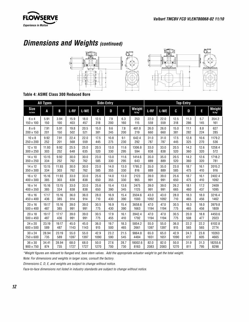
Dimensions and Weights (continued)
Table 4: ASME Class 300 Reduced Bore
All Types Side-Entry Top-Entry
Sizein/mm A B L-RF L-WE C D E Weight
lb/kg* L-RF L-WE C D E Weightlb/kg*
6 x 4150 x 100
5.91150
3.94100
15.9403
18.0457
12.5318
7.9200
6.3160
253115
22.0559
22.0559
12.5318
11.3286
5.7145
354.2161
8 x 6200 x 150
7.91201
5.91150
19.8502
20.5521
15.0381
9.6245
7.8200
481.8219
26.0660
26.0660
15.0381
11.1282
8.8224
627285
10 x 8250 x 200
9.92252
7.91201
22.4568
22.0559
17.5445
10.8275
9.1230
642.4292
31.0787
31.0787
17.5445
12.8325
10.6270
1179.2536
12 x 10300 x 250
11.93303
9.92252
25.5648
25.0635
20.5520
13.0330
11.6295
1306.8594
33.0838
33.0838
20.5520
14.2360
12.6320
1258.4572
14 x 10350 x 250
13.15334
9.92252
30.0762
30.0762
23.0585
13.0330
11.6295
1414.6643
35.0889
35.0889
20.5520
14.2360
12.6320
1718.2781
14 x 12350 x 300
13.15334
11.93303
30.0762
30.0762
23.0585
14.0355
13.0330
1795.2816
35.0889
35.0889
23.0585
18.7475
16.1410
2015.2916
16 x 12400 x 300
15.16385
11.93303
33.0838
33.0838
25.6650
14.0355
13.0330
2123965
39.0991
39.0991
25.6650
18.7475
16.1410
2402.41092
16 x 14400 x 350
15.16385
13.15334
33.0838
33.0838
25.6650
15.4390
13.6345
24751125
39.0991
39.0991
26.2665
18.1460
17.2437
24091095
18 x 16450 x 400
17.17436
15.16385
36.0914
36.0914
28.0710
16.9430
15.4390
3504.61593
43.01092
43.01092
28.0710
18.3465
18.0456
3216.41462
20 x 16500 x 400
19.17487
15.16385
39.0991
39.0991
30.5775
16.9430
15.4390
3658.61663
47.01194
47.01194
30.5775
18.3465
18.0456
3979.81809
20 x 18500 x 450
19.17487
17.17436
39.0991
39.0991
30.5775
17.9455
16.1410
3942.41792
47.01194
47.01194
30.5775
20.0508
18.8477
4450.62023
24 x 20600 x 500
23.19589
19.17487
45.01143
45.01143
36.0915
19.7500
18.3465
5854.22661
55.01397
55.01397
36.0915
22.2565
22.2565
6102.82774
30 x 24750 x 600
28.94735
23.19589
55.01397
55.01397
42.91090
23.2590
21.5545
9864.84484
65.01651
65.01651
42.91090
24.3617
23.8605
102634665
36 x 30900 x 750
34.41874
28.94735
68.01727
68.01727
50.01270
27.6700
28.7730
18002.68183
82.02083
82.02083
50.01270
31.9811
31.3795
18255.68298
*Weight figures are relevant to flanged end, bare stem valves. Add the appropriate actuator weight to get the total weight.
Note: For dimensions and weights in larger sizes, consult the factory.
Dimensions C, D, E, and weights are subject to change without notice.
Face-to-face dimensions not listed in industry standards are subject to change without notice.
L
E
C
BA
D
E
D
L
BA
C
13
Valbart TMCBV FCD VLENTB0068-02 11/10
flowserve.com
Experience in Motion
Dimensions and Weights (continued)
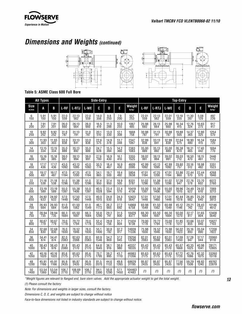
Table 5: ASME Class 600 Full Bore
All Types Side-Entry Top-Entry
Sizein/mm A B L-RF L-RTJ L-WE C D E Weight
lb/kg* L-RF L-RTJ L-WE C D E Weightlb/kg*
6150
5.91150
5.91150
22.0559
22.13562
22.0559
14.0356
9.8250
7.9200
557253
22.01559
22.13562
22.01559
13.19335
11.30287
5.08129
497226
8200
7.91201
7.91201
26.0660
26.13664
26.0660
16.5419
11.3288
10.0255
1067485
25.98660
26.13664
25.98660
16.34415
12.76324
10.83275
917417
10250
9.92252
9.92252
31.0787
31.13791
31.0787
20.1510
13.0330
12.1308
1668758
30.98787
31.13791
30.98787
19.88505
14.37365
12.80325
1254570
12300
11.93303
11.93303
33.0838
33.13841
33.0838
22.6575
14.9378
13.7348
23471067
32.99838
33.13841
32.99838
22.64575
18.90480
16.34415
1584720
14350
13.15334
13.15334
35.0889
35.13892
35.0889
24.7628
15.5394
14.2360
23831083
35.00889
35.13892
35.00889
26.38670
18.31465
17.40442
1694770
16400
15.16385
15.16385
39.0991
39.13994
39.0991
27.6700
16.9430
16.1410
33551525
39.02991
39.13994
39.02991
28.03712
18.50470
18.15461
24461112
18450
17.17436
17.17436
43.01092
43.131095
43.01092
30.5774
18.4467
16.9430
46092095
42.991092
43.131095
42.991092
29.80757
20.16512
18.98482
33511523
20500
19.17487
19.17487
47.01194
47.251200
47.01194
34.1865
19.7500
19.4492
58042638
47.011194
47.251200
47.011194
33.86860
22.44570
22.44570
42681940
22550
21.18538
21.18538
51.01296
51.381305
51.01296
37.4950
37.4950
19.9505
83313787
51.021296
51.381305
51.021296
37.28947
22.76578
23.70602
60722760
24600
23.19589
23.19589
55.01397
55.381406
55.01397
40.51028
23.4594
22.4570
104194736
55.001397
55.381406
55.001397
39.961015
24.49622
24.02610
70693213
26650
24.92633
24.92633
57.01448
57.501460
57.01448
40.01015
24.8630
24.3618
124235647
57.011448
57.501460
57.011448
42.441078
26.85682
25.20640
83893813
28700
26.93684
26.93684
61.01549
61.501562
61.01549
46.11172
26.2665
27.2692
148686758
60.981549
61.501562
60.981549
45.121146
29.21742
28.43722
101464612
30750
28.94735
28.94735
66.31684
65.501697
66.31684
50.81290
29.2741
31.5800
184298377
66.301684
65.501697
66.301684
50.001270
32.17817
31.65804
124085640
32800
30.67779
30.67779
70.01778
70.721794
70.01778
52.41330
29.8756
31.7804
214249738
70.001778
70.721794
70.001778
51.851317
33.66855
33.07840
156277103
34850
32.68830
32.68830
76.01930
76.521946
76.01930
55.11400
30.8782
32.2817
2493911336
75.981930
76.521946
75.981930
56.021423
35.16893
35.04890
172087822
36900
34.41874
34.41874
82.02083
82.632098
82.02083
60.91546
34.2869
37.2945
2925613298
82.012083
82.632098
82.012083
57.091450
37.28947
37.17944
200609118
401000
38.43976
38.43976
81.92080
85.432170
85.42170
64.81645
36.1916
38.6980
4033718335
85.432170
85.432170
85.432170
65.671668
40.351025
40.981041
2817112805
421050
40.161020
40.161020
85.62175
85.632175
85.62175
70.71795
39.2995
43.71110
4698321356
85.632175
85.632175
85.632175
67.721720
42.761086
42.321075
3326015118
481200
45.911166
45.911166
95.92435
95.872435
95.92435
81.52070
44.61132
49.81265
6862931195
95.872435
95.872435
95.872435
77.561970
59.291506
48.821240
4976222619
501400
53.541360
53.541360
106.72710
106.692710
106.72710
94.12390
50.81290
57.11450
10446347483 (1) (1) (1) (1) (1) (1) (1)
*Weight figures are relevant to flanged end, bare stem valves. Add the appropriate actuator weight to get the total weight.
(1) Please consult the factory
Note: For dimensions and weights in larger sizes, consult the factory.
Dimensions C, D, E, and weights are subject to change without notice
Face-to-face dimensions not listed in industry standards are subject to change without notice.
L
E
C
BA
D
E
D
L
BA
C
Valbart TMCBV FCD VLENTB0068-02 11/10
14
Experience in Motion
Dimensions and Weights (continued)
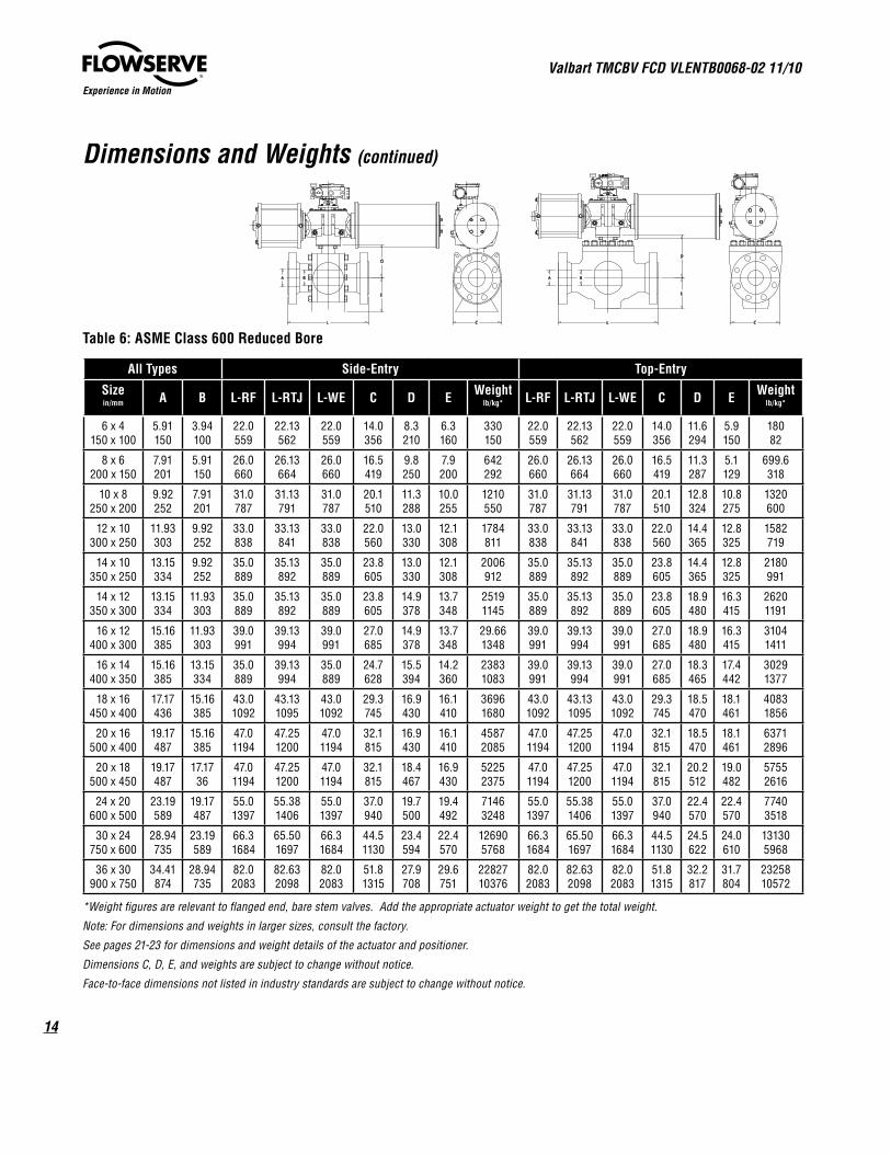
Table 6: ASME Class 600 Reduced Bore
All Types Side-Entry Top-Entry
Sizein/mm A B L-RF L-RTJ L-WE C D E Weight
lb/kg* L-RF L-RTJ L-WE C D E Weightlb/kg*
6 x 4150 x 100
5.91150
3.94100
22.0559
22.13562
22.0559
14.0356
8.3210
6.3160
330150
22.0559
22.13562
22.0559
14.0356
11.6294
5.9150
18082
8 x 6200 x 150
7.91201
5.91150
26.0660
26.13664
26.0660
16.5419
9.8250
7.9200
642292
26.0660
26.13664
26.0660
16.5419
11.3287
5.1129
699.6318
10 x 8250 x 200
9.92252
7.91201
31.0787
31.13791
31.0787
20.1510
11.3288
10.0255
1210550
31.0787
31.13791
31.0787
20.1510
12.8324
10.8275
1320600
12 x 10300 x 250
11.93303
9.92252
33.0838
33.13841
33.0838
22.0560
13.0330
12.1308
1784811
33.0838
33.13841
33.0838
22.0560
14.4365
12.8325
1582719
14 x 10350 x 250
13.15334
9.92252
35.0889
35.13892
35.0889
23.8605
13.0330
12.1308
2006912
35.0889
35.13892
35.0889
23.8605
14.4365
12.8325
2180991
14 x 12350 x 300
13.15334
11.93303
35.0889
35.13892
35.0889
23.8605
14.9378
13.7348
25191145
35.0889
35.13892
35.0889
23.8605
18.9480
16.3415
26201191
16 x 12400 x 300
15.16385
11.93303
39.0991
39.13994
39.0991
27.0685
14.9378
13.7348
29.661348
39.0991
39.13994
39.0991
27.0685
18.9480
16.3415
31041411
16 x 14400 x 350
15.16385
13.15334
35.0889
39.13994
35.0889
24.7628
15.5394
14.2360
23831083
39.0991
39.13994
39.0991
27.0685
18.3465
17.4442
30291377
18 x 16450 x 400
17.17436
15.16385
43.01092
43.131095
43.01092
29.3745
16.9430
16.1410
36961680
43.01092
43.131095
43.01092
29.3745
18.5470
18.1461
40831856
20 x 16500 x 400
19.17487
15.16385
47.01194
47.251200
47.01194
32.1815
16.9430
16.1410
45872085
47.01194
47.251200
47.01194
32.1815
18.5470
18.1461
63712896
20 x 18500 x 450
19.17487
17.1736
47.01194
47.251200
47.01194
32.1815
18.4467
16.9430
52252375
47.01194
47.251200
47.01194
32.1815
20.2512
19.0482
57552616
24 x 20600 x 500
23.19589
19.17487
55.01397
55.381406
55.01397
37.0940
19.7500
19.4492
71463248
55.01397
55.381406
55.01397
37.0940
22.4570
22.4570
77403518
30 x 24750 x 600
28.94735
23.19589
66.31684
65.501697
66.31684
44.51130
23.4594
22.4570
126905768
66.31684
65.501697
66.31684
44.51130
24.5622
24.0610
131305968
36 x 30900 x 750
34.41874
28.94735
82.02083
82.632098
82.02083
51.81315
27.9708
29.6751
2282710376
82.02083
82.632098
82.02083
51.81315
32.2817
31.7804
2325810572
*Weight figures are relevant to flanged end, bare stem valves. Add the appropriate actuator weight to get the total weight.
Note: For dimensions and weights in larger sizes, consult the factory.
See pages 21-23 for dimensions and weight details of the actuator and positioner.
Dimensions C, D, E, and weights are subject to change without notice.
Face-to-face dimensions not listed in industry standards are subject to change without notice.
L
E
C
BA
D
E
D
L
BA
C
15
Valbart TMCBV FCD VLENTB0068-02 11/10
flowserve.com
Experience in Motion
Dimensions and Weights (continued)
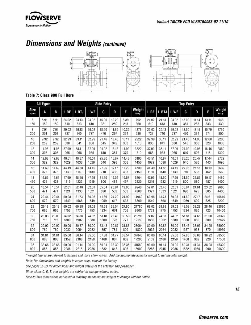
Table 7: Class 900 Full Bore
All Types Side-Entry Top-Entry
Sizein/mm A B L-RF L-RTJ L-WE C D E Weight
lb/kg* L-RF L-RTJ L-WE C D E Weightlb/kg*
6150
5.91150
5.91150
24.02610
24.13613
24.02610
15.00381
10.20259
8.39213
792360
24.02610
24.13613
24.02610
15.00381
11.14283
13.11333
946430
8200
7.91201
7.91201
29.02737
29.13740
29.02737
18.50470
11.69297
10.39264
1276580
29.02737
29.13740
29.02737
18.50470
13.15334
10.79274
1760800
10250
9.92252
9.92252
32.99838
33.11841
32.99838
21.46545
13.46342
13.11333
22221010
32.99838
33.11841
32.99838
21.46545
14.93380
12.60320
22001000
12300
11.93303
11.93303
37.99965
38.11968
37.99965
24.02610
15.12384
14.92379
33221510
37.99965
38.11968
37.99965
24.02610
19.96507
16.46418
28601300
14350
12.68322
12.68322
40.511029
40.871038
40.511029
25.20640
15.67398
14.48368
31901450
40.511029
40.871038
40.511029
25.20640
20.47520
17.44443
37291695
16400
14.69373
14.69373
44.491130
44.881140
44.491130
27.95710
17.17436
17.29437
47302150
44.491130
44.881140
44.491130
27.95710
21.18538
18.19462
56322560
18450
16.65425
16.65423
47.991219
48.501232
47.991219
31.50800
19.06484
19.57497
62042820
47.991219
48.501232
47.991219
31.50800
22.83580
19.17487
74803400
20500
18.54471
18.54471
52.011321
52.481333
52.011321
35.04890
20.94532
19.80503
92404200
52.011321
52.481333
52.011321
35.04890
24.61625
23.82605
96804400
24600
22.44570
22.44570
60.981549
61.731568
60.981549
41.691059
24.29617
24.92633
149606800
60.981549
61.731568
60.981549
41.691059
27.17690
24.61625
158407200
28700
26.18665
26.18665
69.021753
69.881775
69.021753
48.581234
26.54674
27.80706
217809900
69.021753
69.881775
69.021753
48.581234
32.28820
28.46723
2288010400
30750
28.03712
28.03712
74.021880
74.881902
74.021880
51.181300
28.46723
30.59777
2679612180
74.021880
74.881902
74.021880
51.181300
34.65880
31.50800
2832512875
32800
29.92760
29.92760
80.002032
80.872054
80.002032
53.431357
30.87784
31.85809
2600411820
80.002032
80.872054
80.002032
53.431357
36.93938
34.25870
3509015950
34850
31.81808
31.81808
85.002159
86.142188
85.002159
57.801468
31.77807
33.54852
3784017200
85.002159
86.142188
85.002159
57.801468
38.66982
36.22920
3850017500
36900
33.66855
33.66855
90.002286
91.142315
90.002286
60.311532
33.39848
35.35898
4158018900
90.002286
91.142315
90.002286
60.311532
41.341050
38.98990
4532020600
*Weight figures are relevant to flanged end, bare stem valves. Add the appropriate actuator weight to get the total weight.
Note: For dimensions and weights in larger sizes, consult the factory.
See pages 21-23 for dimensions and weight details of the actuator and positioner.
Dimensions C, D, E, and weights are subject to change without notice.
Face-to-face dimensions not listed in industry standards are subject to change without notice.
L
E
C
BA
D
E
D
L
BA
C
Valbart TMCBV FCD VLENTB0068-02 11/10
16
Experience in Motion
Dimensions and Weights (continued)
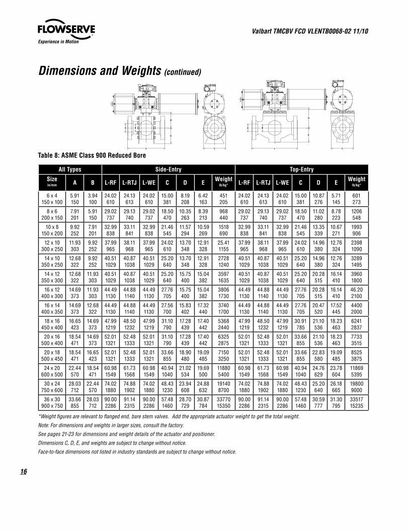
Table 8: ASME Class 900 Reduced Bore
All Types Side-Entry Top-Entry
Sizein/mm A B L-RF L-RTJ L-WE C D E Weight
lb/kg* L-RF L-RTJ L-WE C D E Weightlb/kg*
6 x 4150 x 100
5.91150
3.94100
24.02610
24.13613
24.02610
15.00381
8.19208
6.42163
451205
24.02610
24.13613
24.02610
15.00381
10.87276
5.71145
601273
8 x 6200 x 150
7.91201
5.91150
29.02737
29.13740
29.02737
18.50470
10.35263
8.39213
968440
29.02737
29.13740
29.02737
18.50470
11.02280
8.78223
1206548
10 x 8150 x 200
9.92252
7.91201
32.99838
33.11841
32.99838
21.46545
11.57294
10.59269
1518690
32.99838
33.11841
32.99838
21.46545
13.35339
10.67271
1993906
12 x 10300 x 250
11.93303
9.92252
37.99965
38.11968
37.99965
24.02610
13.70348
12.91328
25.411155
37.99965
38.11968
37.99965
24.02610
14.96380
12.76324
23981090
14 x 10350 x 250
12.68322
9.92252
40.511029
40.871038
40.511029
25.20640
13.70348
12.91328
27281240
40.511029
40.871038
40.511029
25.20640
14.96380
12.76324
32891495
14 x 12350 x 300
12.68322
11.93303
40.511029
40.871038
40.511029
25.20640
15.75400
15.04382
35971635
40.511029
40.871038
40.511029
25.20640
20.28515
16.14410
39601800
16 x 12400 x 300
14.69373
11.93303
44.491130
44.881140
44.491130
27.76705
15.75400
15.04382
38061730
44.491130
44.881140
44.491130
27.76705
20.28515
16.14410
46.202100
16 x 14400 x 350
14.69373
12.68322
44.491130
44.881140
44.491130
27.56700
15.83402
17.32440
37401700
44.491130
44.881140
44.491130
27.76705
20.47520
17.52445
44002000
18 x 16450 x 400
16.65423
14.69373
47.991219
48.501232
47.991219
31.10790
17.28439
17.40442
53682440
47.991219
48.501232
47.991219
30.91785
21.10536
18.23463
62412837
20 x 16500 x 400
18.54471
14.69373
52.011321
52.481333
52.011321
31.10790
17.28439
17.40442
63252875
52.011321
52.481333
52.011321
33.66855
21.10536
18.23463
77333515
20 x 18500 x 450
18.54471
16.65423
52.011321
52.481333
52.011321
33.66855
18.90480
19.09485
71503250
52.011321
52.481333
52.011321
33.66855
22.83580
19.09485
85253875
24 x 20600 x 500
22.44570
18.54471
60.981549
61.731568
60.981549
40.941040
21.02534
19.69500
118805400
60.981549
61.731568
60.981549
40.941040
24.76629
23.78604
118695395
30 x 24750 x 600
28.03712
22.44570
74.021880
74.881902
74.021880
48.431230
23.94608
24.88632
191408700
74.021880
74.881902
74.021880
48.431230
25.20640
26.18665
198009000
36 x 30900 x 750
33.66855
28.03712
90.002286
91.142315
90.002286
57.481460
28.70729
30.87784
3377015350
90.002286
91.142315
90.002286
57.481460
30.59777
31.30795
3351715235
*Weight figures are relevant to flanged end, bare stem valves. Add the appropriate actuator weight to get the total weight.
Note: For dimensions and weights in larger sizes, consult the factory.
See pages 21-23 for dimensions and weight details of the actuator and positioner.
Dimensions C, D, E, and weights are subject to change without notice.
Face-to-face dimensions not listed in industry standards are subject to change without notice.
L
E
C
BA
D
E
D
L
BA
C
17
Valbart TMCBV FCD VLENTB0068-02 11/10
flowserve.com
Experience in Motion
Dimensions and Weights (continued)
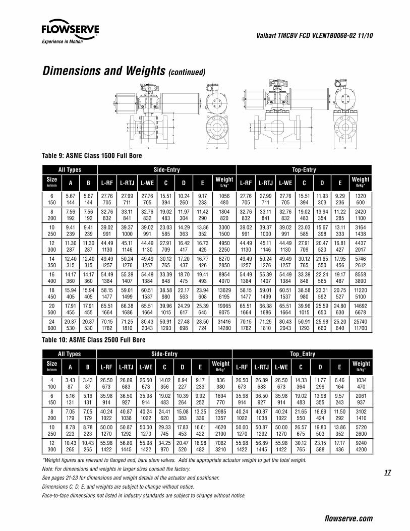
Table 9: ASME Class 1500 Full Bore
All Types Side-Entry Top-Entry
Sizein/mm A B L-RF L-RTJ L-WE C D E Weight
lb/kg* L-RF L-RTJ L-WE C D E Weightlb/kg*
6150
5.67144
5.67144
27.76705
27.99711
27.76705
15.51394
10.24260
9.17233
1056480
27.76705
27.99711
27.76705
15.51394
11.93303
9.29236
1320600
8200
7.56192
7.56192
32.76832
33.11841
32.76832
19.02483
11.97304
11.42290
1804820
32.76832
33.11841
32.76832
19.02483
13.94354
11.22285
24201100
10250
9.41239
9.41239
39.02991
39.371000
39.02991
23.03585
14.29363
13.86352
33001500
39.02991
39.371000
39.02991
23.03585
15.67398
13.11333
31641438
12300
11.30287
11.30287
44.491130
45.111146
44.491130
27.91709
16.42417
16.73425
49502250
44.491130
45.111146
44.491130
27.91709
20.47520
16.81427
44372017
14350
12.40315
12.40315
49.491257
50.241276
49.491257
30.12765
17.20437
16.77426
62702850
49.491257
50.241276
49.491257
30.12765
21.65550
17.95456
57462612
16400
14.17360
14.17360
54.491384
55.391407
54.491384
33.39848
18.70475
19.41493
89544070
54.491384
55.391407
54.491384
33.39848
22.24565
19.17487
85583890
18450
15.94405
15.94405
58.151477
59.011499
60.511537
38.58980
22.17563
23.94608
136296195
58.151477
59.011499
60.511537
38.58980
23.31592
20.75527
112205100
20500
17.91455
17.91455
65.511664
66.381686
65.511664
39.961015
24.29617
25.39645
199659075
65.511664
66.381686
65.511664
39.961015
25.59650
24.80630
146926678
24600
20.87530
20.87530
70.151782
71.251810
80.432043
50.911293
27.48698
28.50724
3141614280
70.151782
71.251810
80.432043
50.911293
25.98660
25.20640
2574011700
Table 10: ASME Class 2500 Full Bore
All Types Side-Entry Top_Entry
Sizein/mm A B L-RF L-RTJ L-WE C D E Weight
lb/kg* L-RF L-RTJ L-WE C D E Weightlb/kg*
4100
3.4387
3.4387
26.50673
26.89683
26.50673
14.02356
8.94227
9.17233
836380
26.50673
26.89683
26.50673
14.33364
11.77299
6.46164
1034470
6150
5.16131
5.16131
35.98914
36.50927
35.98914
19.02483
10.39264
9.92252
1694770
35.98914
36.50927
35.98914
19.02483
13.98355
9.57243
2061937
8200
7.05179
7.05179
40.241022
40.871038
40.241022
24.41620
15.08383
13.35339
29851357
40.241022
40.871038
40.241022
21.65550
16.69424
11.50292
31021410
10250
8.78223
8.78223
50.001270
50.871292
50.001270
29.33745
17.83453
16.61422
46202100
50.001270
50.871292
50.001270
26.57675
19.80503
13.86352
57202600
12300
10.43265
10.43265
55.981422
56.891445
55.981422
34.25870
20.47520
18.98482
70623210
55.981422
56.891445
55.981422
30.12765
23.15588
17.17436
92404200
*Weight figures are relevant to flanged end, bare stem valves. Add the appropriate actuator weight to get the total weight.
Note: For dimensions and weights in larger sizes consult the factory.
See pages 21-23 for dimensions and weight details of the actuator and positioner.
Dimensions C, D, E, and weights are subject to change without notice.
Face-to-face dimensions not listed in industry standards are subject to change without notice.
L
E
C
BA
D
E
D
L
BA
C
Valbart TMCBV FCD VLENTB0068-02 11/10
18
Experience in Motion
Dimensions and Weights (continued)
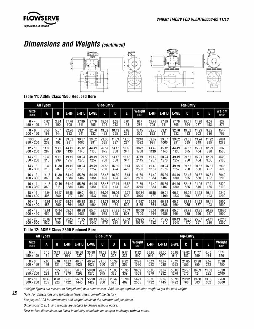
Table 11: ASME Class 1500 Reduced Bore
All Types Side-Entry Top-Entry
Sizein/mm A B L-RF L-RTJ L-WE C D E Weight
lb/kg* L-RF L-RTJ L-WE C D E Weightlb/kg*
6 x 4150 x 100
5.67144
3.94100
27.76705
27.99711
27.76705
15.51394
8.39213
6.61168
627285
27.76705
27.99711
27.76705
15.51394
11.30287
6.02153
827376
8 x 6200 x 150
7.56192
5.67144
32.76832
33.11841
32.76832
19.02483
10.43265
9.02229
1245566
32.76832
33.11841
32.76832
19.02483
11.93303
9.29236
1547703
10 x 8250 x 200
9.41239
7.56192
39.02991
39.371000
39.02991
23.03585
11.69297
11.30287
22481022
39.02991
39.371000
39.02991
23.03585
13.74349
11.22285
28011273
12 x 10300 x 250
11.30287
9.41239
44.491130
45.121146
44.491130
26.57675
14.17360
13.66347
38721760
44.491130
45.121146
44.491130
26.57675
15.91404
12.99330
3371535
14 x 10350 x 250
12.40315
9.41239
49.491257
50.241276
49.491257
29.53750
14.17360
13.66347
47192145
49.491257
50.241276
49.491257
29.53750
15.91404
12.993.30
46202100
14 x 12350 x 300
12.40315
11.30287
49.491257
50.241276
49.491257
29.53750
16.69424
16.61422
55002500
49.4912.57
50.241276
49.791257
29.53750
20.87530
16.81427
59362698
16 x 12400 x 300
14.17360
11.30287
54.491384
55.391407
54.491384
32.48825
16.69424
16.61422
61602800
54.491384
55.391407
54.491384
32.48825
20.87530
16.81427
70403200
16 x 14400 x 350
14.17360
12.40315
54.491384
55.391407
54.491384
32.48825
17.44443
16.85428
71393245
54.491384
55.391407
54.491384
32.48825
21.26540
17.91455
68203100
18 x 16450 x 400
15.94405
14.17360
58151477
59.011499
60.511537
36.06916
19.06484
19.76502
109344970
58151477
59.011499
60.511537
36.06916
21.93557
19.41493
92404200
20 x 16500 x 400
17.91455
14.17360
65.511664
66.381686
35.511664
38.78985
19.06484
19.76502
112975135
65.511664
66.381686
65.511664
38.78985
21.93557
19.41493
99004500
20 x 18500 x 450
17.91455
15.94405
65.511664
66.381686
65.511664
38.78985
21.85555
23.74603
165007500
65.511664
66.381686
65.511664
38.78985
23.35596
20.75527
129805900
24 x 20600 x 500
20.87530
17.91455
70.151782
71.251810
80.432043
46.061170
24.57624
25.31643
2392510875
70.151782
71.251810
80.432043
46.061170
25.87657
24.41620
202409200
Table 12: ASME Class 2500 Reduced BoreAll Types Side-Entry Top-Entry
Sizein/mm A B L-RF L-RTJ L-WE C D E Weight
lb/kg* L-RF L-RTJ L-WE C D E Weightlb/kg*
6 x 4150 x 100
5.16131
3.4387
35.98914
36.50927
35.98914
19.02483
8.94227
9.17233
1122510
35.98914
36.50927
35.98914
19.02483
11.77299
6.46164
1474670
8 x 6200 x 150
7.05179
5.16131
40.241022
40.871038
40.241022
21.65550
10.39264
9.92252
23981090
40.241022
40.871038
40.241022
21.65550
13.98355
9.57243
25301150
10 x 8250 x 200
8.78223
7.05179
50.001270
50.871292
50.001270
26.57675
15.08383
13.35339
36591663
50.001270
50.871292
50.001270
26.57675
16.69424
11.50292
46202100
12 x 10300 x 250
10.43265
8.78223
55.981422
56.891445
55.981422
29.92760
20.47520
18.98482
56212555
55.981422
56.891445
55.981422
29.92760
19.80503
13.86352
72603300
*Weight figures are relevant to flanged end, bare stem valves. Add the appropriate actuator weight to get the total weight.
Note: For dimensions and weights in larger sizes, consult the factory.
See pages 21-23 for dimensions and weight details of the actuator and positioner.
Dimensions C, D, E, and weights are subject to change without notice.
Face-to-face dimensions not listed in industry standards are subject to change without notice.
L
E
C
BA
D
E
D
L
BA
C
19
Valbart TMCBV FCD VLENTB0068-02 11/10
flowserve.com
Experience in Motion
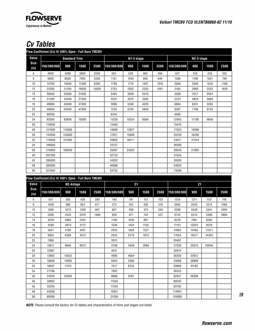
Cv Tables
NOTE: Please consult the factory for Cv tables and characteristics of trims and stages not listed.
Flow Coefficient (Cv) @ 100% Open - Full Bore TMCBV
Valve Size (in)
Standard Trim N1-3 stage N2-3 stage
150/300/600 900 1500 2500 150/300/600 900 1500 2500 150/300/600 900 1500 2500
6 4600 4380 3800 2500 563 536 465 306 647 616 535 352
8 9000 8500 7400 5300 1101 1040 906 649 1266 1196 1041 746
10 14700 14500 11500 8300 1799 1774 1407 1016 2068 2040 1618 1168
12 22500 21100 18000 13000 2753 2582 2203 1591 3165 2969 2532 1829
14 28000 25000 21000 3426 3059 2570 3939 3517 2954
16 37200 34500 27500 4552 4222 3365 5234 4854 3869
18 49000 45000 37000 5996 5506 4528 6894 6331 5205
20 59000 55200 47800 7220 6755 5849 8301 7766 6725
22 68200 8345 9595
24 92000 83800 70000 11258 10254 8566 12943 11790 9848
26 110000 13460 15476
28 121000 113000 14806 13827 17023 15898
30 144000 130000 17621 15908 20259 18290
32 170000 151000 20802 18477 23917 21244
34 189000 23127 26590
36 210000 198200 25697 24253 29545 27885
40 267500 32733 37634
42 280000 34262 39393
48 384000 46988 54025
56 521000 63752 73299
Flow Coefficient (Cv) @ 100% Open - Full Bore TMCBV
Valve Size (in)
N2-4stage C1 Z1
150/300/600 900 1500 2500 150/300/600 900 1500 2500 150/300/600 900 1500 2500
6 531 505 438 288 190 181 157 103 1376 1311 1137 748
8 1038 980 853 611 372 351 305 219 2693 2543 2214 1586
10 1695 1672 1326 957 607 599 475 343 4399 4339 3441 2484
12 2595 2434 2076 1499 929 871 743 537 6733 6314 5386 3890
14 3229 2883 2422 1156 1032 867 8378 7481 6284
16 4290 3979 3172 1536 1424 1135 11131 10323 8229
18 5651 5190 4267 2023 1858 1527 14662 13465 11071
20 6805 6366 5513 2435 2279 1973 17654 16517 14303
22 7866 2815 20407
24 10611 9665 8073 3798 3459 2889 27528 25075 20946
26 12687 4541 32914
28 13955 13033 4995 4664 36206 33812
30 16608 14993 5944 5366 43088 38899
32 19607 17415 7017 6233 50868 45183
34 21798 7802 56553
36 24220 22859 8668 8181 62837 59306
40 30852 11042 80042
42 32293 11558 83782
48 44288 15851 114901
56 60089 21506 155895
Valbart TMCBV FCD VLENTB0068-02 11/10
20
Experience in Motion
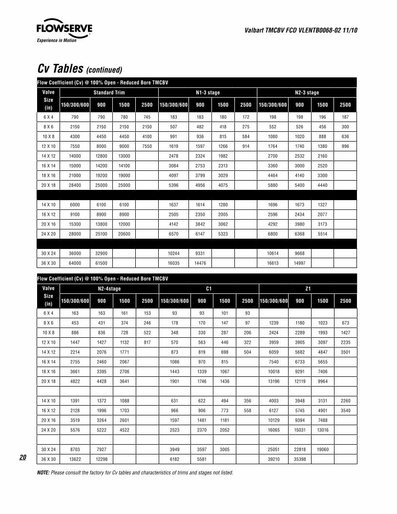
Cv Tables (continued)
NOTE: Please consult the factory for Cv tables and characteristics of trims and stages not listed.
Flow Coefficient (Cv) @ 100% Open - Reduced Bore TMCBV
Valve Size (in)
N2-4stage C1 Z1
150/300/600 900 1500 2500 150/300/600 900 1500 2500 150/300/600 900 1500 2500
6 X 4 163 163 161 153 93 93 101 93
8 X 6 453 431 374 246 178 170 147 97 1239 1180 1023 673
10 X 8 886 836 728 522 348 330 287 206 2424 2289 1993 1427
12 X 10 1447 1427 1132 817 570 563 446 322 3959 3905 3097 2235
14 X 12 2214 2076 1771 873 819 698 504 6059 5682 4847 3501
16 X 14 2755 2460 2067 1086 970 815 7540 6733 5655
18 X 16 3661 3395 2706 1443 1339 1067 10018 9291 7406
20 X 18 4822 4428 3641 1901 1746 1436 13196 12119 9964
14 X 10 1391 1372 1088 631 622 494 356 4003 3948 3131 2260
16 X 12 2128 1996 1703 966 906 773 558 6127 5745 4901 3540
20 X 16 3519 3264 2601 1597 1481 1181 10129 9394 7488
24 X 20 5576 5222 4522 2523 2370 2052 16065 15031 13016
30 X 24 8703 7927 3949 3597 3005 25051 22818 19060
36 X 30 13622 12298 6182 5581 39210 35398
Flow Coefficient (Cv) @ 100% Open - Reduced Bore TMCBV
Valve Size (in)
Standard Trim N1-3 stage N2-3 stage
150/300/600 900 1500 2500 150/300/600 900 1500 2500 150/300/600 900 1500 2500
6 X 4 790 790 780 745 183 183 180 172 198 198 196 187
8 X 6 2150 2150 2150 2150 507 482 418 275 552 526 456 300
10 X 8 4300 4450 4450 4100 991 936 815 584 1080 1020 888 636
12 X 10 7550 8000 9000 7550 1619 1597 1266 914 1764 1740 1380 996
14 X 12 14000 12800 13000 2478 2324 1982 2700 2532 2160
16 X 14 15000 14200 14100 3084 2753 2313 3360 3000 2520
18 X 16 21000 19200 19000 4097 3799 3029 4464 4140 3300
20 X 18 28400 25000 25000 5396 4956 4075 5880 5400 4440
14 X 10 6000 6100 6100 1637 1614 1280 1696 1673 1327
16 X 12 9100 8900 8900 2505 2350 2005 2596 2434 2077
20 X 16 15300 13800 12000 4142 3842 3062 4292 3980 3173
24 X 20 28000 25100 20600 6570 6147 5323 6800 6368 5514
30 X 24 36000 32900 10244 9331 10614 9668
36 X 30 64000 61500 16035 14476 16613 14997
21
Valbart TMCBV FCD VLENTB0068-02 11/10
flowserve.com
Experience in Motion
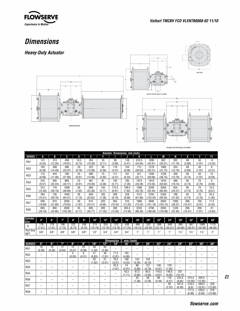
DimensionsHeavy-Duty Actuator
Actuator Dimensions, mm (inch)SERIES A B C D E F I J K L M N X Y Y1
RG1 141(5.55)
310(12.20)
498(19.61)
18,5(0.73)
264(10.39)
55(2.17)
99(3.90)
139(5.47)
610.5(24.04)
1090(42.91)
902(35.51)
282(11.10)
68(2.68)
50(1.97)
-9(-0.35)
RG2 162(6.38)
368(14.49)
586(23.07)
20(0.79)
322(12.68)
65(2.56)
116(4.57)
154(6.06)
712(28.03)
1278(50.31)
1060(41.73)
324(12.76)
68(2.68)
50(1.97)
8(0.31)
RG3 175(6.98)
444(17.48)
706(27.80)
23(0.91)
380(14.96)
75(2.95)
111(4.37)
161(6.34)
817(32.17)
1500(59.06)
1238(48.74)
350(13.78)
95(3.74)
50(1.97)
15(0.59)
RG4 243(9.57)
565(22.24)
868(34.17)
23(0.91)
467(18.39)
91(3.58)
145(5.71)
185(7.28)
1074(42.28)
1919(75.55)
1616(63.62)
486(19.13)
95(3.74)
70(2.76)
0(0.00)
RG5 312(12.28)
716(28.19)
1008(39.69)
26(1.02)
568(22.36)
145(5.71)
175.5(6.91)
199.5(7.85)
1366(53.78)
2348(92.44)
2056(80.94)
624(24.57)
95(3.74)
70(2.76)
15.5(0.61)
RG6 394(15.51)
756(29.76)
1640(64.57)
28(1.10)
600(23.62)
185(7.28)
208(8.19)
228(8.98)
1572(61.89)
3184(125.35)
2300(90.55)
788(31.02)
95(3.74)
70(2.76)
25.5(1.00)
RG7 500(19.69)
810(31.89)
2030(79.92)
50(1.97)
615(24.21)
220(8.66)
265(10.43)
310(12.20)
1860(73.23)
3840(151.18)
2620(103.15)
1000(39.37)
266(10.47)
150(5.91)
11.5(0.45)
RG8 665(26.18)
860(33.86)
2600(102.36)
55(2.17)
680(26.77)
280(11.02)
306(12.05)
365.5(14.39)
2245(88.39)
4790(188.58)
3050(120.08)
1330(52.36)
266(10.47)
200(7.87)
-21(-0.83)
Cylinder Size 5" 6" 7" 8" 9" 10" 12" 14" 16' 18" 20" 22" 24" 28" 32" 36" 40"
G 178(7.01)
178(7.01)
196(7.72)
222(8.74)
248(9.76)
274(10.79)
324(12.76)
375(14.76)
438(17.24)
486(19.13)
532(20.94)
588(23.15)
648(25.51)
865(34.06)
967(38.07)
1069(42.09)
1170(46.06)
Port Size NPT 3/8˝ 3/8˝ 3/8˝ 3/8˝ 3/8˝ 1/2˝ 3/4˝ 3/4˝ 3/4˝ 1˝ 1˝ 1˝ 1˝ 1½˝ 1½˝ 1½˝ 2˝
Dimension Z, mm (inch)SERIES 5" 6" 7" 8" 9" 10" 12" 14" 16' 18" 20' 22" 24" 28" 32" 36" 40"RG1 10
(0.39)10
(0.39)11
(0.04)12
(0.47)25
(0.98)38
(1.50)63
(2.48) – – – – – – – – – –
RG2 – – – 5(0.20)
8(0.31)
21(0.83)
46(1.81)
71,5(2.81)
103(4.06) – – – – – – – –
RG3 – – – – – 26(1.02)
51(2.01)
76,5(3.01)
108(4.25)
132(5.20)
155(6.10) – – – – – –
RG4 – – – – – – – 42,5(1.67)
74(2.91)
98(3,86)
121(4.76)
149(5.87)
179(7.05) – – – –
RG5 – – – – – – – – 43,5(1.71)
67,5(2.66)
90,5(3.56)
118,5(4.67)
148,5(5.85)
257(10.12) – – –
RG6 – – – – – – – – – 35(1.38)
58(2.28)
86(3.39)
116(4.57)
224,5(8.84)
275,5(10.85)
326,5(12.85) –
RG7 – – – – – – – – – – – – 59(2.32)
167,5(6.59)
218,5(8.6)
269,5(10.61)
320(12.60)
RG8 – – – – – – – – – – – – – – 177,5(6.99)
228,5(9.00)
279(10.98)

Valbart TMCBV FCD VLENTB0068-02 11/10
22
Experience in Motion
DimensionsHeavy-Duty Actuator
Dimensions for Spring Return Tandem Cylinders, mm (inch)SERIES A B C E G N LRG8 32-32 665
(26.18)1715
(67.52)2600
(102.36)680
(26.77)1170
(46.06)1330
52.36)5645
(222.24)
RG836-36 665(26.18)
1740(68.50)
2600102.36)
680(26.77)
1170(46.06)
133052.36)
5670(223.23)
Actuator Weights
Model Kg Lbs Model Kg Lbs
RG1 DA 61 135 RG5 DA 620 1360
RG1 DD 79 174 RG5 DD 786 1734
RG1 SR 148 326 RG5 SR 1409 3106
RG2 DA 113 248 RG6 DA 1211 2671
RG2 DD 135 298 RG6 DD 1379 3041
RG2 SR 275 606 RG6 SR 2714 5985
RG3 DA 210 462 RG7 DA 2290 5049
RG3 DD 247 544 RG7 DD 3046 6716
RG3 SR 466 1028 RG7 SR 4320 9525
RG4 DA 400 883 RG8 DA 3581 7895
RG4 DD 442 974 RG8 DD 5471 12062
RG4 SR 826 1822 RG8 SR 6955 15335
*DA - Double Acting
**DD - Dual Cylinder
***Spring Return
Double Acting Tandem Cylinder
EG
B A
C
A
N
L
23
Valbart TMCBV FCD VLENTB0068-02 11/10
flowserve.com
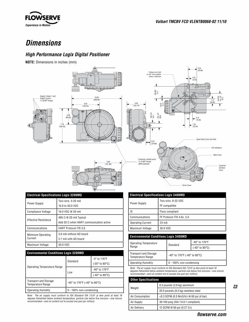
Experience in Motion
DimensionsHigh Performance Logix Digital PositionerNOTE: Dimensions in inches (mm)
Electrical Specifications Logix 3200MD
Power SupplyTwo-wire, 4-20 mA
10.0 to 30.0 VDC
Compliance Voltage 10.0 VDC @ 20 mA
Effective Resistance495 Ω @ 20 mA Typical
Add 20 Ω when HART communication active
Communications HART Protocol ITK 5,6
Minimum Operating Current
3.6 mA without AO board
3.7 mA with AO board
Maximum Voltage 30.0 VDC
Environmental Conditions Logix 3200MD
Operating Temperature Range
Standard-4° to 176°F
(-20° to 80°C)
Low-40° to 176°F
(-40° to 80°C)
Transport and Storage Temperature Range -40° to 176°F (-40° to 80°C)
Operating Humidity 0 - 100% non-condensing
Note: The air supply must conform to ISA Standard ISA 7.0.01 (a dew point at least 18 degrees Fahrenheit below ambient temperature, particle size below five microns—one micron recommended—and oil content not to exceed one part per million).
Electrical Specifications Logix 3400MD
Power SupplyTwo-wire, 9-32 VDC
FF compatible
IS Fisco compliant
Communications FF Protocol ITK 4.6x, 5.0
Operating Current 23 mA
Maximum Voltage 36.0 VDC
Environmental Conditions Logix 3400MD
Operating Temperature Range Standard
-40° to 176°F
(-40° to 80°C)
Transport and Storage Temperature Range -40° to 176°F (-40° to 80°C)
Operating Humidity 0 - 100% non-condensing
Note: The air supply must conform to ISA Standard ISA 7.0.01 (a dew point at least 18 degrees Fahrenheit below ambient temperature, particle size below five microns—one micron recommended—and oil content not to exceed one part per million).
Other Specifications
Weight8.3 pounds (3.9 kg) aluminum
20.5 pounds (9.3 kg) stainless steel
Air Consumption <0.3 SCFM (0.5 Nm3/hr) @ 60 psi (4 bar)
Air Supply 30-150 psig (ISA 7.0.0.1 compliant)
Air Delivery 12 SCFM @ 60 psi (0.27 Cv)
5.92(150.24)
10.63(269.92)
3.38(85.83)
7.18(182.45)
4.05(102.74)
1.24(31.59)
0.86(21.76)
0.97(24.69)
4.00(101.60)
Customer conduit ports½-14 NPT thread(M20 optional)
Supply, Output 1 andOutput 2 ports¼-18 NPT thread
LED Indicators
Main Cover
Customer Interface Cover
Spool Valve Cover and Vent
Driver Cover
0.15(3.81)
2.70(68.68)
2.25(57.15)Square
5.24(133.15)1.13
(28.58)
2.00(50.80)
0.25(6.35)
1.00(25.40)
0.75(19.05)
Follower arm limitis ±45° from position
shown, maximum
5.92(150.24)
10.63(269.92)
3.38(85.83)
7.18(182.45)
4.05(102.74)
1.24(31.59)
0.86(21.76)
0.97(24.69)
4.00(101.60)
Customer conduit ports½-14 NPT thread(M20 optional)
Supply, Output 1 andOutput 2 ports¼-18 NPT thread
LED Indicators
Main Cover
Customer Interface Cover
Spool Valve Cover and Vent
Driver Cover0.15(3.81)
2.70(68.68)
2.25(57.15)Square
5.24(133.15)1.13
(28.58)
2.00(50.80)
0.25(6.35)
1.00(25.40)
0.75(19.05)
Follower arm limitis ±45° from position
shown, maximum5.92
(150.24)
10.63(269.92)
3.38(85.83)
7.18(182.45)
4.05(102.74)
1.24(31.59)
0.86(21.76)
0.97(24.69)
4.00(101.60)
Customer conduit ports½-14 NPT thread(M20 optional)
Supply, Output 1 andOutput 2 ports¼-18 NPT thread
LED Indicators
Main Cover
Customer Interface Cover
Spool Valve Cover and Vent
Driver Cover
0.15(3.81)
2.70(68.68)
2.25(57.15)Square
5.24(133.15)1.13
(28.58)
2.00(50.80)
0.25(6.35)
1.00(25.40)
0.75(19.05)
Follower arm limitis ±45° from position
shown, maximum
Experience in Motion
To find your local Flowserve representative:
For more information about Flowserve Corporation, visit www.flowserve.com or call USA 1 800 225 6989
Flowserve Valbart20050 Mezzago (Milan) ItalyTelephone: +39.039.624111Fax: +39.039.6241178www.flowserve.com
Flowserve Houston Business Development5909 West Loop South, Suite 200Telephone: +1 713 218 4200Fax: +1 713 218 4247
Flowserve Corporation has established industry leadership in the design and manufacture of its products. When properly selected, this Flowserve Corporation product is designed to perform its intended function safely during its useful life. However, the purchaser or user of Flowserve Corporation products should be aware that Flowserve Corporation products might be used in numerous applications under a wide variety of industrial service conditions. Although Flowserve Corporation can (and often does) provide general guidelines, it cannot provide specific data and warnings for all possible applications. The purchaser/user must therefore assume the ultimate responsibility for the proper sizing and selection, installation, operation, and maintenance of Flowserve Corporation products. The purchaser/user should read and understand the Installation Operation Maintenance (IOM) instructions included with the product, and train its employees and contractors in the safe use of Flowserve Corporation products in connection with the specific application.
While the information and specifications contained in this literature are believed to be accurate, they are supplied for informative purposes only and should not be considered certified or as a guarantee of satisfactory results by reliance thereon. Nothing contained herein is to be construed as a warranty or guarantee, express or implied, regarding any matter with respect to this product. Because Flowserve Corporation is continually improving and upgrading its product design, the specifications, dimensions and information contained herein are subject to change without notice. Should any question arise concerning these provisions, the purchaser/user should contact Flowserve Corporation at any one of its worldwide operations or offices.
© 2010 Flowserve Corporation, Irving, Texas, USA. Flowserve is a registered trademark of Flowserve Corporation.
FV VLENTB0068-02 Printed in USA.