super compact 5 watt uhf cb radio - gme australia · pdf filesuper compact 5 watt uhf cb radio...
TRANSCRIPT
Super compact 5 watt UHF CB radio
ScanSuite™5 YEAR WARRANTY
I N S T R U C T I O N M A N U A L
PA G E 2 I N S T R U C T I O N M A N UA L T X 3 1 2 0 S
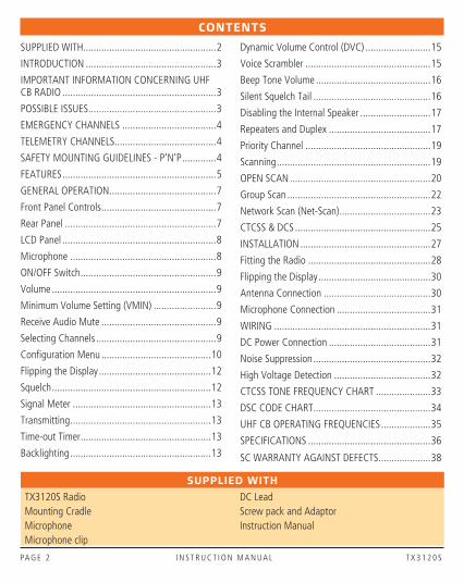
SUPPLIED WITH
TX3120S Radio DC LeadMounting Cradle Screw pack and AdaptorMicrophone Instruction ManualMicrophone clip
CONTENTS
SUPPLIED WITH ...................................................2
INTRODUCTION ..................................................3
IMPORTANT INFORMATION CONCERNING UHF CB RADIO ...........................................................3
POSSIBLE ISSUES .................................................3
EMERGENCY CHANNELS ....................................4
TELEMETRY CHANNELS.......................................4
SAFETY MOUNTING GUIDELINES - P’N’P .............4
FEATURES ...........................................................5
GENERAL OPERATION .........................................7
Front Panel Controls ............................................7
Rear Panel ..........................................................7
LCD Panel ...........................................................8
Microphone ........................................................8
ON/OFF Switch ....................................................9
Volume ...............................................................9
Minimum Volume Setting (VMIN) ........................9
Receive Audio Mute ............................................9
Selecting Channels ..............................................9
Configuration Menu ..........................................10
Flipping the Display ...........................................12
Squelch .............................................................12
Signal Meter .....................................................13
Transmitting ......................................................13
Time-out Timer ..................................................13
Backlighting ......................................................13
Dynamic Volume Control (DVC) .........................15
Voice Scrambler ................................................15
Beep Tone Volume ............................................16
Silent Squelch Tail .............................................16
Disabling the Internal Speaker ...........................17
Repeaters and Duplex .......................................17
Priority Channel ................................................19
Scanning ...........................................................19
OPEN SCAN ......................................................20
Group Scan .......................................................22
Network Scan (Net-Scan) ...................................23
CTCSS & DCS ....................................................25
INSTALLATION ..................................................27
Fitting the Radio ...............................................28
Flipping the Display ...........................................30
Antenna Connection .........................................30
Microphone Connection ....................................31
WIRING ............................................................31
DC Power Connection .......................................31
Noise Suppression .............................................32
High Voltage Detection .....................................32
CTCSS TONE FREQUENCY CHART .....................33
DSC CODE CHART .............................................34
UHF CB OPERATING FREQUENCIES ...................35
SPECIFICATIONS ...............................................36
SC WARRANTY AGAINST DEFECTS ....................38
T X 3 1 2 0 S I N S T R U C T I O N M A N UA L PA G E 3
INTRODUCTION
The TX3120S is Australian designed and engineered combining the latest in electronic hardware with up-to-date computer aided design and manufacturing techniques to produce an extremely compact mobile radio with outstanding specifications and performance.
Your radio is designed for unobtrusive mounting in modern vehicles. With its built-in loud speaker, speaker microphone and extremely small size, it can be mounted in almost any convenient location.
IMPORTANT INFORMATION CONCERNING UHF CB RADIO
The use of the Citizen Band radio service is licensed in Australia by the ACMA Radio communications (Citizens Band Radio Stations) Class Licence and in New Zealand by the Ministry of Economic Development New Zealand (MED).
A General User Radio Licence for Citizens Band radio and operation is subject to conditions contained in those licences.
The class licence for users and equipment operating in the CB/PRS 477 MHz band has been amended. This radio meets the new 80 channel standard.
In simple terms the same amount of spectrum is available; however, radio transceivers can now operate in a narrower bandwidth and hence use less spectrum. These radios are generally referred to as narrowband or 12.5 kHz radios. By using 12.5 kHz channel spacing instead of 25 kHz, the 40 channels originally allocated can now be expanded to 80 channels thereby doubling the channel capacity and relieving congestion in the UHF CB/PRS band.
Original 40 channel wideband Radios will continue to operate on the original 40 channels, however they will not be able to converse on the newer channels 41 – 80. The newer narrowband radios will be able to converse with all older 40 channel wideband radios on all channels 1 to 40 as well as the newer channels allocated from 41 to 80.
The mixing of narrowband and wideband radios in the same spectrum can cause some possible operating issues of interference and varying levels of received volume.
POSSIBLE ISSUES
When a new narrowband radio receives a transmission from an older wideband radio the speech may sound loud and distorted – simply adjust your radio volume for best performance.
When an older wideband radio receives a signal from a new narrowband radio, the speech may sound quiet – simply adjust your radio volume for best performance.
Depending on how close your receiving radio is to another transmitting radio, there can be interference from the transmitting radio if it is using a channel adjacent to the channel you are listening to. Simply try going up or down a few channels from the currently selected channel.
The above situations are not a fault of the radio but a symptom of operating wideband and narrowband radios in the same bandwidth. This possible interference will decrease over time as the population of wideband radios ages and decreases.
Further information and updates are available from the Australian Communications and Media Authority (ACMA) at www.acma.gov.au and the Ministry of Economic Development (MED), Radio Spectrum Management at: www.rsm.govt.nz
PA G E 4 I N S T R U C T I O N M A N UA L T X 3 1 2 0 S
EMERGENCY CHANNELS
The ACMA has allocated channels 5/35 for emergency use only. Channel 5 is the primary Simplex Emergency Channel. Where a Channel 5 repeater is available, you should select Duplex on CH 5.
NOTE: Channel 35 is the input channel for the Channel 5 repeater therefore Channel 35 should also not be used for anything other than emergency transmissions.
TELEMETRY CHANNELS
ACMA regulations have allocated channels 22 and 23 for telemetry only applications and have prohibited the transmission of speech on these channels. Consequently your radio has a transmit inhibit applied to channels 22 and 23.
In the event additional telemetry/telecommand channels are approved by the ACMA, these channels shall be added to those currently listed where voice transmission is inhibited. Currently transmissions on channels 61, 62 and 63 are also inhibited and these channels are reserved for future allocation.
SAFETY MOUNTING GUIDELINES FOR PLUG ‘N’ PLAY
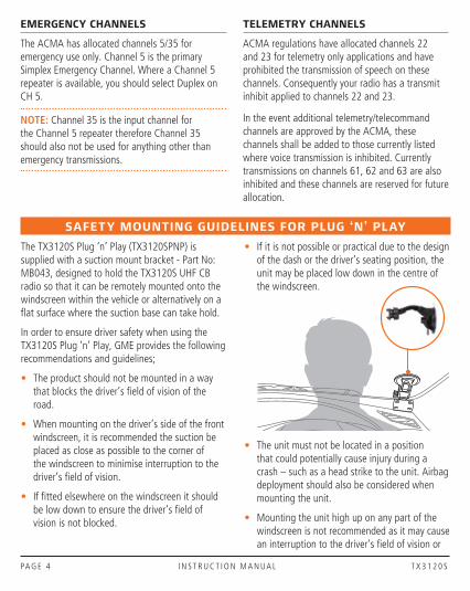
The TX3120S Plug ‘n’ Play (TX3120SPNP) is supplied with a suction mount bracket - Part No: MB043, designed to hold the TX3120S UHF CB radio so that it can be remotely mounted onto the windscreen within the vehicle or alternatively on a fl at surface where the suction base can take hold.
In order to ensure driver safety when using the TX3120S Plug ‘n’ Play, GME provides the following recommendations and guidelines;
• The product should not be mounted in a way that blocks the driver’s fi eld of vision of the road.
• When mounting on the driver’s side of the front windscreen, it is recommended the suction be placed as close as possible to the corner of the windscreen to minimise interruption to the driver’s fi eld of vision.
• If fi tted elsewhere on the windscreen it should be low down to ensure the driver’s fi eld of vision is not blocked.
• If it is not possible or practical due to the design of the dash or the driver’s seating position, the unit may be placed low down in the centre of the windscreen.
• The unit must not be located in a position that could potentially cause injury during a crash – such as a head strike to the unit. Airbag deployment should also be considered when mounting the unit.
• Mounting the unit high up on any part of the windscreen is not recommended as it may cause an interruption to the driver’s fi eld of vision or

T X 3 1 2 0 S I N S T R U C T I O N M A N UA L PA G E 5
FEATURES
TRANSMIT (TX)
Individually Programmable DUPLEX Function: User selectable for only those individual channels in your area that have repeaters, leaving the others free for use as extra simplex channels.
RECEIVE (RX)
Silent Squelch Tail: Eliminates the Squelch noise burst normally audible when the Squelch closes
Signal Receive Indicator: Confirms that an incoming signal is being received
SCANNING AND MEMORY FUNCTIONS
Microprocessor Controlled Frequency Synthesiser: Allows user programmable control of scanning, channel memories and selected feature options.
Programmable Scan Function: Scans the selected UHF CB channels with Group, Open and Network scan functions available.
Priority Channel: A user programmable Priority channel feature allows your working channel to be instantly recalled at the press of a key
SIGNAL PROCESSING
Digital Signal Processing: Measures filters and compresses standard analogue audio signals and converts them into digital format. Allows advanced RF and audio processing techniques to be applied to maximise the radio’s performance.
Advanced Signal Management: Identifies interference caused by strong local signals on adjacent channels and prevents these from opening your Squelch. ASM also minimises distortion on reception by fine tuning the receiver frequency to match that of the incoming signal.
Dynamic Volume Control: Automatically compensates for variations in received audio level to provide a constant audio output level to the speaker.
interfere with rear view mirrors and sun visors. It may also result in the DC power lead trailing in the field of vision.
• Deciding on the location of the unit should also factor where power leads may need to run to avoid the possibility of them interfering with or becoming entangled in vehicle controls.
• Covering or restricting access to dash instruments and controls is not recommended.
The responsibility of deciding the location of where the unit is mounted rests entirely with the end-user and should be carefully considered to ensure compliance with any state or federal laws.
PA G E 6 I N S T R U C T I O N M A N UA L T X 3 1 2 0 S
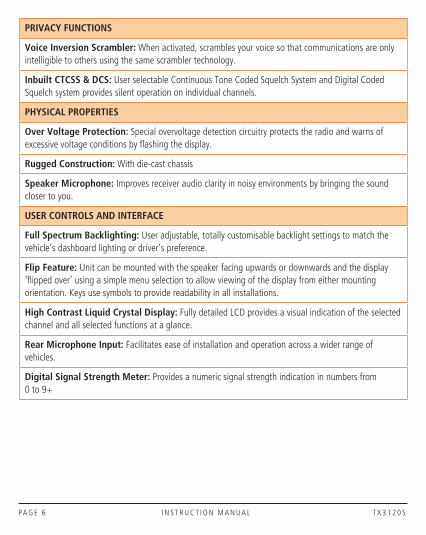
PRIVACY FUNCTIONS
Voice Inversion Scrambler: When activated, scrambles your voice so that communications are only intelligible to others using the same scrambler technology.
Inbuilt CTCSS & DCS: User selectable Continuous Tone Coded Squelch System and Digital Coded Squelch system provides silent operation on individual channels.
PHYSICAL PROPERTIES
Over Voltage Protection: Special overvoltage detection circuitry protects the radio and warns of excessive voltage conditions by flashing the display.
Rugged Construction: With die-cast chassis
Speaker Microphone: Improves receiver audio clarity in noisy environments by bringing the sound closer to you.
USER CONTROLS AND INTERFACE
Full Spectrum Backlighting: User adjustable, totally customisable backlight settings to match the vehicle’s dashboard lighting or driver’s preference.
Flip Feature: Unit can be mounted with the speaker facing upwards or downwards and the display ‘flipped over’ using a simple menu selection to allow viewing of the display from either mounting orientation. Keys use symbols to provide readability in all installations.
High Contrast Liquid Crystal Display: Fully detailed LCD provides a visual indication of the selected channel and all selected functions at a glance.
Rear Microphone Input: Facilitates ease of installation and operation across a wider range of vehicles.
Digital Signal Strength Meter: Provides a numeric signal strength indication in numbers from 0 to 9+
T X 3 1 2 0 S I N S T R U C T I O N M A N UA L PA G E 7
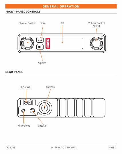
REAR PANEL
FRONT PANEL CONTROLS
GENERAL OPERATION
Volume Control On/Off
LCDChannel Control
Squelch
Scan
DC Socket
Speaker
Antenna
Microphone
PA G E 8 I N S T R U C T I O N M A N UA L T X 3 1 2 0 S
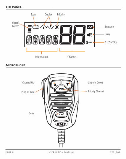
MICROPHONE
LCD PANEL
Channel DownChannel Up
Push To Talk
Scan
Priority Channel
Priority
Busy
Transmit
DuplexScan
ChannelInformation
CTCSS/DCS
Signal Meter

T X 3 1 2 0 S I N S T R U C T I O N M A N UA L PA G E 9
ON/OFF SWITCH
Press the Volume control to turn the radio on. Press and hold the Volume control to turn the radio off.
VOLUME
Rotate the Volume control left or right to adjust the volume. During volume adjustment the Volume level is displayed on the LCD as ‘VOL01’ (minimum) to ‘VOL31’ (maximum).
MINIMUM VOLUME SETTING (VMIN)
By default, when the Volume control is set to minimum (VOL01) there is still a sufficient level of residual audio from an incoming signal to be heard in a quiet cabin environment. If required, the minimum volume level can be adjusted through the ‘VMIN’ option in the Menu.
To adjust the minimum volume level
1. Press and hold the Channel control to enter the menu. The display will show the current Squelch level setting.
2. Rotate the Channel control until ‘VMINx’ is displayed (where ‘x’ is a value from 1 – 9), then press the Channel control to select it. The VMIN value will be flashing.
3. Rotate the Channel control to make the desired selection from 1 – 9. For the lowest minimum volume level select 1.
When finished briefly press the Channel Control to return to the menu or press and hold the Channel Control to exit the menu.
RECEIVE AUDIO MUTE
There may be times when it is desirable to temporarily override the minimum volume setting and completely mute the receiver audio.
To mute the receiver audio, briefly press the Volume control. ‘MUTE’ will flash on the display and the receiver audio will be muted. During this time you may see the icon appear but no sound will be heard in the speaker.
To unmute the receiver audio, briefly press (or rotate) the Volume control again. ‘MUTE’ will be removed from the display and the receiver audio will be restored to its previous volume setting.
SELECTING CHANNELS
To select the required channel, rotate the Channel control (or press the or keys on the microphone). Rotate the Channel control clockwise (or press the key ) to select a higher channel or counter clockwise (or press the key) to select lower channels. The selected channel is displayed on the LCD.

PA G E 1 0 I N S T R U C T I O N M A N UA L T X 3 1 2 0 S
CONFIGURATION MENU
The configuration menu provides access to all the radio’s preset settings.
To use the menu
1. Press and hold the Channel control until a beep is heard. The radio will enter the menu and the first menu item (Squelch level) will be displayed.
2. Rotate the Channel Control left or right to select the required menu item then press the Channel control to edit it. The selected item will flash.
3. Rotate the Channel control to adjust the selected item.
a. To save the current setting and return to the menu, briefly press the Channel control.
b. To exit without saving and return to the menu, briefly press the Volume control.
c. To save the current setting, exit the menu and return to normal operation, press and hold the Channel control or simply wait a few seconds for the menu to time-out.
The following Menu items (page 10) are available:
SQLWHITE
COLOR
BKLGT
FLIP
SST
BCL
VMIN
S-METDVC
CTCSS
NETSCAN
SCAN
PRIORITY
DUP
SPK
BEEP
ENC
Volume Control On/OffChannel Control
Selected Menu Item
T X 3 1 2 0 S I N S T R U C T I O N M A N UA L PA G E 1 1
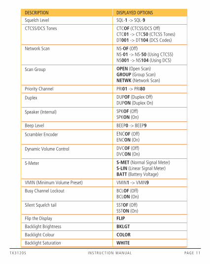
DESCRIPTION DISPLAYED OPTIONS
Squelch Level SQL-1 -> SQL-9
CTCSS/DCS Tones CTCOF (CTCSS/DCS Off)CTC01 -> CTC50 (CTCSS Tones)DT001 -> DT104 (DCS Codes)
Network Scan NS-OF (Off)NS-01 -> NS-50 (Using CTCSS)NS001 -> NS104 (Using DCS)
Scan Group OPEN (Open Scan)GROUP (Group Scan)NETWK (Network Scan)
Priority Channel PRI01 -> PRI80
Duplex DUPOF (Duplex Off)DUPON (Duplex On)
Speaker (Internal) SPKOF (Off)SPKON (On)
Beep Level BEEP0 -> BEEP9
Scrambler Encoder ENCOF (Off)ENCON (On)
Dynamic Volume Control DVCOF (Off)DVCON (On)
S-Meter S-MET (Normal Signal Meter)S-LIN (Linear Signal Meter)BATT (Battery Voltage)
VMIN (Minimum Volume Preset) VMIN1 -> VMIN9
Busy Channel Lockout BCLOF (Off)BCLON (On)
Silent Squelch tail SSTOF (Off)SSTON (On)
Flip the Display FLIP
Backlight Brightness BKLGT
Backlight Colour COLOR
Backlight Saturation WHITE
PA G E 1 2 I N S T R U C T I O N M A N UA L T X 3 1 2 0 S
FLIPPING THE DISPLAY
The TX3120S’s small size allows it to be mounted in almost any convenient location. However the most suitable location may sometimes require the unit to be installed upside-down when referenced to your driving position.
The TX3120S is designed to overcome this situation by allowing the display to be ‘flipped’ so that it can be read in either orientation. In addition the keys have symbols that can also be read in either orientation.
To flip the display
1. Press and hold the Channel control to enter the menu. The display will show the present Squelch level.
2. Rotate the Channel control until ‘FLIP’ is displayed then briefly press the Channel control to select it. ‘FLIP’ will flash.
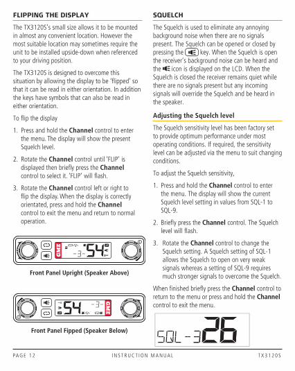
3. Rotate the Channel control left or right to flip the display. When the display is correctly orientated, press and hold the Channel control to exit the menu and return to normal operation.
Front Panel Upright (Speaker Above)
Front Panel Fipped (Speaker Below)
SQUELCH
The Squelch is used to eliminate any annoying background noise when there are no signals present. The Squelch can be opened or closed by pressing the key. When the Squelch is open the receiver’s background noise can be heard and the icon is displayed on the LCD. When the Squelch is closed the receiver remains quiet while there are no signals present but any incoming signals will override the Squelch and be heard in the speaker.
Adjusting the Squelch level
The Squelch sensitivity level has been factory set to provide optimum performance under most operating conditions. If required, the sensitivity level can be adjusted via the menu to suit changing conditions.
To adjust the Squelch sensitivity,
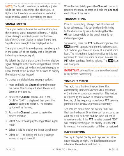
1. Press and hold the Channel control to enter the menu. The display will show the current Squelch level setting in values from SQL-1 to SQL-9.
2. Briefly press the Channel control. The Squelch level will flash.
3. Rotate the Channel control to change the Squelch setting. A Squelch setting of SQL-1 allows the Squelch to open on very weak signals whereas a setting of SQL-9 requires much stronger signals to overcome the Squelch.
When finished briefly press the Channel control to return to the menu or press and hold the Channel control to exit the menu.
T X 3 1 2 0 S I N S T R U C T I O N M A N UA L PA G E 1 3
NOTE: The Squelch level can be actively adjusted while the radio is scanning. This allows you to tighten the Squelch in cases where an undesired weak or noisy signal is interrupting the scan.
SIGNAL METER
The signal meter indicates the relative strength of the incoming signal in numerical format. A digital signal strength level is displayed on the lower left of the Channel Display in values from 0 to 9. Signals above strength 9 are displayed as 9+.
The signal strength is also displayed on a bar graph in the upper left of the display with a longer bar indicating a stronger signal.
By default the digital signal strength meter displays signal strengths in the standard logarithmic format however it can be set to display signal strengths in linear format or the location can be used to display the battery voltage instead.
To change the digital signal strength options;
1. Press and hold the Channel control to enter the menu. The display will show the current Squelch level setting.
2. Rotate the Channel control until ‘S-MET’, ‘S-LIN’ or ‘BATT’ is displayed then press the Channel control to select it. The selected option will be flashing.
3. Rotate the Channel control to make the desired selection.
• Select ‘S-MET’ to display the logarithmic signal meter.
• Select ‘S-LIN’ to display the linear signal meter.
• Select ‘BATT’ to display the battery voltage instead of signal strength.
When finished briefly press the Channel control to return to the menu or press and hold the Channel control to exit the menu.
TRANSMITTING
Prior to transmitting, always check the channel is not being used. This can be done by listening to the channel or by visually checking that the
icon is not visible or the signal meter is not indicating a signal.
To transmit, press the PTT on the microphone. The icon will appear. Hold the microphone about
5-8 cm from your face and speak at a normal voice level. The microphone is quite sensitive so it is not necessary to raise your voice or shout. Release the PTT when you have finished talking. The icon will disappear.
IMPORTANT: Always listen to ensure the channel is free before transmitting.
TIME-OUT TIMER
The radio has a built-in time-out timer that automatically limits transmissions to a maximum of 3 minutes of continuous operation. This feature is required by the ACMA to prevent accidental blocking of the frequency should your PTT become jammed or be otherwise pressed accidentally.
Ten seconds before time-out occurs, ‘TOT’ will flash on the display. Once time-out has occurred an alert beep will be heard and the radio will return to receive mode. If the PTT remains pressed, ‘TOT’ will continue flashing on the display until the PTT is released. Normal operation will then be restored.
BACKLIGHTING
The Liquid Crystal Display and keys are backlit for easier viewing at night. The backlight remains on whenever the radio is switched on.

PA G E 1 4 I N S T R U C T I O N M A N UA L T X 3 1 2 0 S
Adjusting the Backlighting
The backlight brightness and colour can be adjusted via the menu for personal preference. There are three backlight settings available.
BKLGT (Brightness setting): Provides a continuously variable brightness adjustment from very dim to full brightness.
COLOR (Colour setting): Provides a continuously variable adjustment through the full colour spectrum.
White (Whiteness setting): Controls the colour saturation of the selected colour from deep colour to white (no colour).
To adjust the backlighting;
Press and hold the Channel control to enter the menu. The display will show the current Squelch level setting.
Brightness
1. Rotate the Channel control left or right until ‘BKLGT’ is displayed then briefly press the Channel control to select it. ‘BKLGT’ will flash.
2. Rotate the Channel control left or right to adjust the display brightness. Rotate right to increase the brightness or left to decrease the brightness.
3. Briefly press the Channel control to return to the menu.
Colour
1. Rotate the Channel control to the right until ‘COLOR’ is displayed then briefly press the Channel control to select it. ‘COLOR’ will flash.
2. Rotate the Channel control left or right to adjust the colour.
3. Briefly press the Channel control to return to the menu.
Whiteness
1. Rotate the Channel control to the right until ‘WHITE’ is displayed then briefly press the Channel control to select it. ‘WHITE’ will flash.
2. Rotate the Channel control left or right to adjust the colour saturation (whiteness). Rotate right to reduce the colour intensity or left to increase it.
3. Briefly press the Channel control to return to the menu or press and hold the Channel control to exit the menu and return to normal operation.
Auto-colour Mode
The radio has an automatic colour-change option that, when activated, will cause the display colour to automatically cycle through the available colour spectrum. The colour-change option can be enabled temporarily as an aid to choosing a display colour or can be set to cycle continuously as the preferred display colour setting.
To enable the auto-colour option,
1. Press and hold the Channel control to enter the menu. The display will show the current Squelch level setting.
2. Rotate the Channel control left or right until ‘COLOR’ is displayed.
3. While ‘COLOR’ is displayed, briefly press the key to enable or disable the auto-colour
option. When enabled, the display lighting will continuously cycle through the available colour spectrum. When disabled the display will hold the last selected colour.

T X 3 1 2 0 S I N S T R U C T I O N M A N UA L PA G E 1 5
When finished briefly press the Channel control to return to the menu or press and hold the Channel control to exit the menu. If auto-colour is still enabled, the display lighting will continue to cycle through the colour spectrum until disabled using the steps above.
DYNAMIC VOLUME CONTROL (DVC)
The modulation level of signals heard on the UHF CB band can vary considerably resulting in noticeable differences in received audio volume. Often users compensate for this by adjusting the Volume control for each incoming signal. With the introduction of 80 channel narrowband transmissions using lower levels of modulation, the diversity in received audio volume has increased further. Your TX3120S is fitted with a Dynamic Volume Control feature which, when activated, automatically compensates for these variations in audio level resulting in a constant audio output level to the speaker.
To activate the Dynamic Volume Control
1. Press and hold the Channel control to enter the menu. The display will show the current Squelch level setting.
2. Rotate the Channel control until ‘DVCOF’ or ‘DVCON’ is displayed then press the Channel control to select it. ‘ON’ or ‘OF’ will be flashing.
3. Rotate the Channel control to make the desired selection. Select ‘DVCON’ to switch the Dynamic Volume Control ON or ‘DVCOF’ to switch it OFF.
When finished briefly press the Channel control to return to the menu or press and hold the Channel control to exit the menu.
Dynamic Volume Control ON
Dynamic Volume Control OFF
VOICE SCRAMBLER
Your radio incorporates a simple voice scrambler using band inversion. The scrambler is compatible with the majority of scramblers used by other manufacturers, allowing you to enjoy scrambled communications with owners of non-GME radios. Once the scrambler has been activated your transmission and reception will only be intelligible to others using the same scrambler technology.
To enable or disable the voice scrambler
1. Press and hold the Channel control to enter the menu. The display will show the current Squelch level setting.
2. Rotate the Channel control until ‘ENCOF’ or ‘ENCON’ is displayed then press the Channel control to select it. ‘ON’ or ‘OF’ will be flashing.
3. Rotate the Channel control to the right to enable the scrambler encoder. ‘ENCON’ will be displayed.
4. Rotate the Channel control to the left to disable the Scrambler encoder. ‘ENCOF’ will be displayed.
When finished briefly press the Channel control to return to the menu or press and hold the Channel control to exit the menu.

PA G E 1 6 I N S T R U C T I O N M A N UA L T X 3 1 2 0 S
Scrambler Encoder ON
Scrambler Encoder OFF
BEEP TONE VOLUME
The Beep Tone provides audible feedback whenever the keys are pressed. You can adjust the volume of the key beeps as follows.
1. Press and hold the Channel control to enter the menu. The display will show the current Squelch level setting.
2. Rotate the Channel control until ‘BEEPx’ is displayed (where x is a beep volume level from 0 – 9) then press the Channel control to select it. The beep volume level will be flashing
3. Rotate the Channel control to adjust the Beep volume from 0 – 9. To switch the Beep Tone OFF select 0.
When finished briefly press the Channel control to return to the menu or press and hold the Channel control to exit the menu.
Beep level = 2
SILENT SQUELCH TAIL
The Squelch tail is the short burst of noise that is heard in the speaker at the end of a transmission just before the Squelch closes. To some it is a reassuring confirmation that it is their turn to transmit but in some applications it may be an annoyance especially when listening through an earpiece or headphones.
The Silent Squelch Tail function removes this noise, reducing it to a faint click as the Squelch closes.
To enable or disable the Silent Squelch Tail
1. Press and hold the Channel control to enter the menu. The display will show the current Squelch level setting.
2. Rotate the Channel control until ‘SSTxx’ is displayed (where xx = ON or OF), then press the Channel control to select it. ‘ON’ or ‘OF’ will be flashing.
3. Rotate the Channel control to the right to enable the Silent Squelch Tail. ‘SSTON’ will be displayed and the Squelch Tail will become silent.
4. Rotate the Channel control to the left to disable the Silent Squelch Tail. ‘SSTOF’ will be displayed and the Squelch Tail will be restored.
When finished briefly press the Channel control to return to the menu or press and hold the Channel control to exit the menu.
Silent Squelch Tail On
Silent Squelch Tail OFF
T X 3 1 2 0 S I N S T R U C T I O N M A N UA L PA G E 1 7
DISABLING THE INTERNAL SPEAKER
The TX3120S has two speakers – one mounted inside the radio and the other mounted inside the microphone. By default, sound is reproduced by both speakers; however if you prefer, the radio’s internal speaker can be switched off leaving just the speaker/microphone to reproduce sound.
To switch off the radio’s internal speaker
1. Press and hold the Channel control to enter the menu. The display will show the current Squelch level setting.
2. Rotate the Channel control until ‘SPKxx’ is displayed (where xx = ON or OF), then press the Channel control to select it. ‘ON’ or ‘OF’ will be flashing.
3. Rotate the Channel control to the right to switch the internal speaker ON. ‘SPKON’ will be displayed.
4. Rotate the Channel control to the left to switch the internal speaker OFF. ‘SPKOF’ will be displayed.
When finished briefly press the Channel control to return to the menu or press and hold the Channel control to exit the menu.
REPEATERS AND DUPLEX
Duplex operation allows the radio to transmit on a different frequency to that which it receives. This allows operation through repeater stations.
A repeater station consists of a linked transmitter/receiver combination installed in a prominent location. The repeater is designed to receive signals on a designated channel and retransmit them on another channel. Repeaters are usually mounted on hills or tall buildings. The increase elevation greatly improves both the receiving and transmitting range of the repeater allowing it to receive and retransmit signals to radios that would otherwise be out of range of each other.
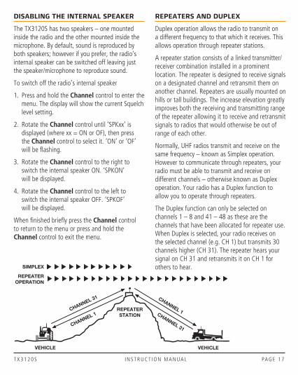
Normally, UHF radios transmit and receive on the same frequency – known as Simplex operation. However to communicate through repeaters, your radio must be able to transmit and receive on different channels – otherwise known as Duplex operation. Your radio has a Duplex function to allow you to operate through repeaters.
The Duplex function can only be selected on channels 1 – 8 and 41 – 48 as these are the channels that have been allocated for repeater use. When Duplex is selected, your radio receives on the selected channel (e.g. CH 1) but transmits 30 channels higher (CH 31). The repeater hears your signal on CH 31 and retransmits it on CH 1 for others to hear.
CHANNEL 31
CHANNEL 1
CHANNEL 1CHANNEL 31
VEHICLE
SIMPLEX
REPEATEROPERATION
VEHICLE
REPEATERSTATION

PA G E 1 8 I N S T R U C T I O N M A N UA L T X 3 1 2 0 S
Your radio allows you to enable or disable Duplex mode on individual repeater channels. In this way any repeater channels that are not being used with repeaters in your area can be used in Simplex mode for normal direct radio-to-radio communications.
To enable or disable Duplex on a Repeater Channel
1. Select the required repeater channel (1 – 8, 41 – 48).
2. Press and hold the Channel control to enter the menu. The display will show the current Squelch level setting.
3. Rotate the Channel control until ‘DUPxx’ is displayed (where xx = ON or OF), then press the Channel control to select it.
NOTE: If ‘DUP- -‘ is displayed, the selected channel is not a repeater channel. Please exit the menu and select a repeater channel.
4. Rotate the Channel control to the right to enable Duplex on the selected channel. ‘DUPON’ will be displayed and the icon will appear.
5. Rotate the Channel control to the left to disable Duplex on the selected channel. ‘DUPOF’ will be displayed and the icon will disappear.
When finished press and hold the Channel control to exit the menu.
Repeater channel not selected
Duplex On
Duplex Off
Channel Selected
Receive Channel
Transmit Channel
1 1 31
2 2 32
3 3 33
4 4 34
5* 5* 35*
6 6 36
7 7 37
8 8 38
41 41 71
42 42 72
43 43 73
44 44 74
45 45 75
46 46 76
47 47 77
48 48 78
*Emergency channel only

T X 3 1 2 0 S I N S T R U C T I O N M A N UA L PA G E 1 9
IMPORTANT: Channels 1 – 8, 31 – 38, 41 – 48 and 71 – 78 should only be used in Simplex mode if there are no repeaters in or near your location that operate on the selected channel. In particular, avoid operating in Simplex mode on any of the repeater input channels 31 – 38 and 71 – 78 unless you are absolutely sure that there are no repeaters in range using that channel. Inadvertently transmitting on an active repeater input frequency in simplex mode could cause interference to other users on that repeater that would not be audible to your radio.
PRIORITY CHANNEL
The Priority channel feature allows you to instantly recall any one of the 80 channels in your radio. This feature can be used to provide instant access to your working channel or your local repeater channel at the press of key. It is also used in conjunction with the Group Scan mode.
To store a Priority Channel;
1. Press and hold the Channel control to enter the menu. The display will show the current Squelch level setting.
2. Rotate the Channel control until ‘PRIxx’ is displayed (where xx is a number from 01 - 80), then press the Channel control to select it.
3. Rotate the Channel control to select your required priority channel number.
When finished press and hold the Channel control to exit the menu.
Priority channel = 80
To recall a Priority Channel;
Briefly press the Channel control. The radio will immediately switch to the Priority channel. The priority channel is identified by the * icon.
PriorityChannel
Icon
NOTE: If the radio was scanning when the Priority channel was recalled, the scan will be cancelled.
SCANNING
Your radio incorporates a scan function allowing selected groups of channels to be scanned for signals. Channels can be scanned at a rate of 45 channels per second. When a signal is found, scanning will pause to allow the signal to be heard then resume scanning when the channel is clear again.
Scan Groups
Your radio supports three scan groups - Open Scan, Group Scan and Network Scan. Each scan group has separate channel memories allowing you to program your choice of channels into each group for scanning.
Selecting a Scan Group
To select Open Scan, Group Scan or Network Scan;
1. Press and hold the Channel control to enter the menu. The display will show the current Squelch level setting.
2. Rotate the Channel control until ‘OPEN’, ‘GROUP’ or NETWK’ is displayed, then press the Channel control to select it.
PA G E 2 0 I N S T R U C T I O N M A N UA L T X 3 1 2 0 S
3. Rotate the Channel control to select your required Scan Group. Select ‘OPEN’ for Open Scan, ‘GROUP’ for Group Scan or ‘NETWK’ for Network Scan.
When finished press and hold the Channel control to exit the menu.
Open Scan
Group Scan
Network Scan
NOTE: Network scan is disabled by default and will not appear in the scan group list unless it has been enabled. See Network Scan further below for details on how to enable and use Network Scan.
Auto Skip
While scanning, if an active channel in your scan group becomes a nuisance by constantly interrupting the scan, briefly rotate the Channel control (or press the or keys) while the radio is paused on that channel. The busy channel will be temporarily removed from the scan group to allow time for the channel to become clear again and scanning will continue from the next channel in the sequence. After 30 seconds the skipped channel will be reinstated in the scan sequence.
If the unwanted active channel continues to interrupt the scan after the 30 second skip period has elapsed, hold the key while the radio is paused on that channel to completely remove that channel from the scan group for the duration of the scan session. To restore the channel, simply stop and restart the scan session using the key (or switch the radio Off then On again).
NOTE: You can skip as many busy channels from the scan group as you wish, however if you attempt to skip the last remaining channel, all the previously skipped channels will be restored to the scan group.
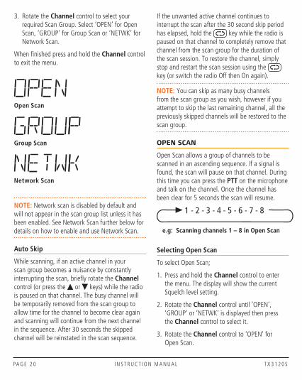
OPEN SCAN
Open Scan allows a group of channels to be scanned in an ascending sequence. If a signal is found, the scan will pause on that channel. During this time you can press the PTT on the microphone and talk on the channel. Once the channel has been clear for 5 seconds the scan will resume.
e.g: Scanning channels 1 – 8 in Open Scan
1 - 2 - 3 - 4 - 5 - 6 - 7 - 8
Selecting Open Scan
To select Open Scan;
1. Press and hold the Channel control to enter the menu. The display will show the current Squelch level setting.
2. Rotate the Channel control until ‘OPEN’, ‘GROUP’ or ‘NETWK’ is displayed then press the Channel control to select it.
3. Rotate the Channel control to ‘OPEN’ for Open Scan.

T X 3 1 2 0 S I N S T R U C T I O N M A N UA L PA G E 2 1
When finished press and hold the Channel control to exit the menu.
Programming the Scan Memory
Your radio has all 80 channels factory-programmed into the Open Scan memory. Any channels not required can be removed.
To add or remove channels from the Open Scan memory:
1. Select the required channel using the Channel control (or the or keys).
2. Check to see if the symbol is displayed on that channel.
• If is displayed, the selected channel is already in the scan memory. To remove it, press and hold the key. will disappear from the display.
• If is not displayed, the selected channel is not in the scan memory. To add it, press and hold the key. will now be displayed on that channel.
Repeat to add or remove other channels in the scan memory.
Default Working Channel in Open Scan Mode
In the Open Scan mode, your default working channel is the channel your radio switches to when you press the PTT while scanning. To define your working channel simply select the required channel before you press the key. e.g. to make channel 24 your working channel, simply select channel 24 before pressing the key.
To Begin Scanning
Briefly press the key. A high beep will be heard and the symbol will animate. During
this time the channel numbers will scroll rapidly as the channels are scanned.
NOTE: If there are less than 2 channels programmed into the scan memory when you press the key, a low beep will sound and the command will be ignored.
Operating in the Open Scan Mode
• If a busy channel is found, scanning will pause to allow the signal to be heard and will remain there for as long as the channel remains busy. Once the channel has been clear for 5 seconds, scanning will resume automatically.
• If you don’t wish to listen to a busy channel, briefly rotate the Channel control (or press the
or keys) while the radio is paused on that channel. The busy channel will be temporarily removed from the scan group to allow time for the channel to become clear again and scanning will continue. The skipped channel will be reinstated in the scan sequence after 30 seconds (see Auto Skip).
• If you press the PTT while the radio is scanning, the scan will pause and the radio will transmit on the working channel. After the channel has remained clear for 5 seconds scanning will resume.
• If your radio pauses on a busy channel and you wish to talk on that channel, simply press the PTT during a break in the conversation. If the busy channel was not your working channel, it now becomes your new working channel, replacing your previous one. Once your communication has finished and the channel has been clear for 5 seconds, scanning will resume.

PA G E 2 2 I N S T R U C T I O N M A N UA L T X 3 1 2 0 S
• If you need to use your Priority channel (for an urgent call), briefly press the Channel control. The scan will be cancelled and the radio will jump straight to the Priority channel.
GROUP SCAN
Group Scan allows you to scan a number of channels for activity whilst also monitoring your Priority channel. The receiver will scan the other channels ONLY WHILE THERE ARE NO SIGNALS ON THE PRIORITY CHANNEL. If a signal appears on the Priority channel it will override any signals being received on any of the other channels. In addition, if you press the PTT at any time, the radio will transmit on the Priority channel.
e.g: Scanning channels 1 – 8 with priority channel 20 in Group Scan
1 - 2 - 3 - 4 - 20 - 5 - 6 - 7 - 8 - 20
Selecting Group Scan
To select Group Scan;
1. Press and hold the Channel control to enter the menu. The display will show the current Squelch level setting.
2. Rotate the Channel control until ‘OPEN’, ‘GROUP’ or NETWK’ is displayed then press the Channel control to select it.
3. Rotate the Channel control to ‘GROUP’ for Group Scan.
When finished press and hold the Channel control to exit the menu.
Programming the Scan Memory
1. Select the required channel using the Channel control (or press the or keys).
2. Check to see if the symbol is displayed on that channel.
• If is displayed, the selected channel is already in the scan memory. To remove it, press and hold the key. will disappear from the display.
• If is not displayed, the selected channel is not in the scan memory. To add it, press and hold the key. will now be displayed on that channel.
Repeat to add or remove other channels in the scan memory.
Select your Priority Channel
Program your Priority channel as described earlier under ‘Priority Channel’.
Operating in the Group Scan Mode
To begin scanning, briefly press the key. A high beep will be heard and the icon will animate. During this time the channel numbers will change rapidly as the channels are scanned with the Priority channel scanned every fourth channel.
• If a signal appears on the Priority channel – at any time – the radio will switch directly to the Priority channel and will stay there for as long as the channel remains busy. During this time you can transmit and receive on the Priority channel. Once the Priority channel has been clear for 5 seconds the radio will resume scanning the other channels.
• If a signal appears on any other channel, scanning will pause on that channel and will remain there while the channel is busy – as long as there are no signals on the Priority channel. During this time, the receiver will continue to check the Priority channel every 2 seconds resulting in a series of small breaks
T X 3 1 2 0 S I N S T R U C T I O N M A N UA L PA G E 2 3
in the reception of the busy channel. Once the signal has gone and there has been no activity for 5 seconds, the radio will resume scanning.
• To transmit on the Priority channel at any time, simply press the PTT. The radio will switch straight to the Priority channel. When you have finished your conversation and there has been no further activity for 5 seconds, the radio will resume scanning the other channels. If you don’t wish to listen to a busy channel, briefly rotate the Channel control (or press the or keys) while the radio is paused on that channel. The busy channel will be temporarily removed from the scan group to allow time for the channel to become clear again and scanning will continue. The skipped channel will be reinstated in the scan sequence after 30 seconds (see Auto Skip).
• If you need to use your Priority channel (for an urgent call), briefly press the Channel control. The scan will be cancelled and the radio will jump straight to the Priority channel.
• If the radio is paused on a busy channel and you want to remain there, briefly press the
key. The radio will exit scan and remain on the busy channel. At this point you will no longer be monitoring the Priority channel. To resume Group scanning press the key again.
NETWORK SCAN (NET-SCAN)
Net-Scan allows a group of radio users to maintain communications even when the band is congested. To achieve this all members of the Net-Scan group must share a common CTCSS/DCS code and a common set of scan channels.
Once activated, Net-Scan’s intelligent scanning software keeps track of clear channels within
your scan group. When any member of the group transmits, their radio automatically selects a clear channel to transmit on. Other radios scanning in the same Net-scan group will lock onto that channel allowing all members of the group to join the conversation.
If a signal from outside your Net-Scan group appears on the chosen channel (either with no code or the wrong code), the group will automatically switch to a new clear channel at the next transmission. In this way the group can continue to communicate with minimal interference to or from other users.
Enabling Net-Scan
Net-Scan is normally switched off by default but can be enabled through your radio’s menu.
NOTE: When you enable Net-Scan you will also be prompted to choose a suitable CTCSS or DCS tone to be used by your Net-Scan group. All members of your Net-Scan group must use this same code.
To Enable Net-Scan
1. Press and hold the Channel control to enter the menu. The display will show the current Squelch level setting.
2. Rotate the Channel control until ‘NS xxx’ is displayed (where xxx is the current Net-Scan setting) then press the Channel control to select it.
3. Rotate the Channel control to change the current Net-Scan setting.
• To enable Net-Scan using CTCSS, select from NS-01 to NS-50 (CTCSS tones 01 to 50).
• To enable Net-Scan using DCS, select from NS001 to NS104 (DCS codes 001 to 104).

PA G E 2 4 I N S T R U C T I O N M A N UA L T X 3 1 2 0 S
• To disable Net-Scan, select NS-OF.
When finished press and hold the Channel control to exit the menu.
Selecting Net-Scan
Once Net-Scan is enabled, a Network Scan option becomes available in the scan group selection. To select Network Scan;
1. Press and hold the Channel control to enter the menu. The display will show the current Squelch level setting.
2. Rotate the Channel control until ‘OPEN’, ‘GROUP’ or NETWK’ is displayed then press the Channel control to select it.
3. Rotate the Channel control to ‘NETWK’ for Network Scan.
When finished press and hold the Channel control to exit the menu.
Programming Channels into Net-Scan
All radios in your Net-Scan group must have the same channels programmed into their Net-Scan memory.
Your radio’s Net-Scan memory has already been factory programmed with 43 of the available 80 channels. The remaining 37 channels, which consist of the 32 repeater input/output channels, 2 telemetry channels and 3 guard band channels, have not been included to minimise the risk of interference to other services on these channels.
To Add or Remove Net-Scan Channels
With Net-Scan mode enabled,
1. Select the required channel using the Channel control (or the or keys).
2. Check to see if the scan symbol is displayed on that channel.
• If is displayed, the selected channel is already in the scan memory. To remove it, press and hold the key. will disappear.
• If is not displayed, the selected channel is not in the scan memory. To add it, press and hold the key. will now be displayed on that channel.
Repeat to add or remove further Net-Scan channels.
IMPORTANT: When adding channels to Net-Scan, please consider the following:
The transmitter on your radio is inhibited on channels 22, 23 and channels 61, 62, 63 as required by the ACMA. This makes these channels unsuitable for use as Net-Scan channels.
You should not include any repeater channel unless you have confirmed that the channel is not allocated to a repeater in your area. Using an active repeater channel in Net-Scan may result in interference to other repeater users on that channel.
Starting Net-Scan
With Net-Scan mode enabled, press the key. A high beep will be heard and the icon will animate. During this time the channel numbers will change rapidly as the channels are scanned.
Using Net-Scan
When a member of the group initiates a transmission their radio will automatically select a clear channel to transmit on. Other radios scanning in the same Net-Scan group will locate the transmission by identifying the group’s CTCSS/DCS code and open their Squelch allowing the
T X 3 1 2 0 S I N S T R U C T I O N M A N UA L PA G E 2 5
transmission to be heard across the entire group. When the transmission ends, all radios in the group will immediately resume scanning.
If a member of the group responds to the initial transmission, they will automatically re-use the same channel as long as the channel remains free of other signals. This allows the radios in the group to respond more quickly to further transmissions from others in the group.
If at any time, a signal from outside your Net-Scan group appears on the channel (either with no code or the wrong code), the channel will be discarded and a new clear channel will be selected at the next transmission. The other radios in the group will then locate the new channel allowing the conversation to continue seamlessly without any input from the user.
Ending the Scan
To stop scanning, briefly press the key. A low beep will be heard and the animated icon will stop. As long as the radio was not on a busy channel, it will return to the last channel you selected, otherwise it will stay on the busy channel.
CTCSS & DCS
The standard Squelch system is fine for quieting the radio in most applications. However, it operates solely on signal strength which means that it will always open to any signal that is strong enough. If the channel is busy with other stations the Squelch will be constantly opening making it difficult to determine which calls are meant for you.
CTCSS (Continuous Tone Coded Squelch System) and DCS (Digital Coded Squelch) are similar Squelch quieting systems that provide selective audio muting using sub-audible signalling. When enabled, only signals with a matching sub-tone will be heard in the speaker. This effectively creates a
channel that is silent to all traffic except those you wish to hear.
Choosing CTCSS or DCS
The CTCSS system uses 1 of 50 low frequency tones to open and close the Squelch on the radio. The DCS system is similar to CTCSS but uses 1 of 104 digital codes to control the Squelch. There is no difference in performance or function between the different tone sets so choosing which tone system to use will largely depend on the other radios you talk with. If others already use CTCSS or DCS, you should select the tone system that matches theirs. If the users you talk to don’t currently use CTCSS or DCS then you can make your own choice. Both types are included in the radio to maintain compatibility with other radio systems.
CTCSS Tone Set Compatibility
The GME CTCSS tone set comprises a table of 50 tones made up of the standard CCIR-38 Tone Set plus an additional 12 tones added to the end. If communicating with other brands of radios that only use the CCIR-38 tone set, please select from one of the first 38 tones to ensure compatibility with these radios.
If communicating with other GME radios, you may choose from any of the 50 tones. However, please refer to the tone set tables listed in each radio’s Instruction manual for compatibility. Although the same 50 tones are available in all GME radios, the tones used in older GME models may be listed in a different order to those in your radio.
To select a CTCSS or DCS code
1. Press and hold the Channel control to enter the menu. The display will show the current Squelch level setting.
PA G E 2 6 I N S T R U C T I O N M A N UA L T X 3 1 2 0 S
2. Rotate the Channel control until ‘CTCxx’ or ‘DTxxx’ is displayed then press the Channel control to select it.
3. Rotate the Channel control to enable CTCSS/DCS and select a suitable CTCSS or DCS code.
• To use CTCSS, select from CTC01 to CTC50 (CTCSS tones 01 to 50).
• To use DCS, scroll past CTC50 to select from DT001 to DT104 (DCS codes 001 to 104).
• To switch CTCSS/DCS off, select CTCOF.
When finished press and hold the Channel control to exit the menu.
Enabling CTCSS/DCS on a Channel (Silent mode)
Enabling CTCSS/DCS on a channel will prevent the Squelch from opening on that channel unless the incoming signal matches your selected CTCSS/DCS tone. Other users on the same channel who are not using your CTCSS/DCS tone will still be received by your radio (the icon will still appear on the display) – but their voice will not be heard in the speaker.
Only when someone transmits on the channel using your CTCSS/DCS tone will the Squelch open to allow the signal to be heard. Channels where CTCSS/DCS have been enabled are said to be in ‘Silent mode’. Silent mode can be enabled on any channel except emergency channels 5 and 35.
NOTE: You cannot enable Silent mode unless a CTCSS or DCS tone has been selected in the Configuration menu. If CTCSS/DCS has been set to OFF, Silent mode is inhibited.
To Enable Silent Mode on a channel:
1. Select the required channel.
2. Press and hold the key until a high beep is heard.
3. An icon (for CTCSS) or icon (for DCS) will be displayed in the lower right of the display to indicate Silent mode is now enabled on that channel.
NOTE: The CTCSS/DCS tone you selected will be used for all channels that have ‘Silent’ enabled.
To Disable Silent Mode on a channel:
1. Select the required channel. An icon (for CTCSS) or icon (for DCS) will be displayed indicating Silent mode is currently enabled.
2. Press and hold the key until a low beep is heard.
3. The or icon will disappear to indicate Silent mode has been removed from that channel.
IMPORTANT: When Silent mode is enabled on a channel you should always look for the icon for signs of traffic on the channel before transmitting to ensure you do not accidentally transmit over the top of another user. Alternatively, you can enable ‘Busy Channel Lockout’ in the Configuration Menu which will automatically prevent your radio from transmitting if the channel is already in use.
Busy Channel Lockout
When using Silent mode with CTCSS/DCS, you may not notice when others outside your CTCSS/DCS group are transmitting on your channel. As a result you could accidentally transmit over the top of someone else.
T X 3 1 2 0 S I N S T R U C T I O N M A N UA L PA G E 2 7
The Busy Channel Lockout function detects when others outside your CTCSS/DCS group are transmitting on the channel and prevents your radio from transmitting over them. If the channel is busy and you press the PTT the radio will emit a warning beep and the icon won’t appear. When you release the PTT, look for the icon on the display as an indicator that the channel is in use. If the channel is busy, simply wait until the channel is clear and press the PTT again.
NOTE: You can also press the Monitor key to open the Squelch and listen for signals on the channel before transmitting (see Monitor Function directly below).
To enable Busy Lockout
1. Press and hold the Channel control to enter the menu. The display will show the current Squelch level setting.
2. Rotate the Channel control until ‘BCLxx’ is displayed (where xx = ‘ON’ or ‘OF’).
• Rotate the Channel control to the right to enable Busy Channel Lockout. ‘BCLON’ will be displayed.
• Rotate the Channel control to the left to disable Busy Lockout. ‘BCLOF’ will be displayed.
When finished press and hold the Channel control to exit the menu.
Monitor Function
When the current channel is in Silent mode, the icon may appear but no sound will be heard in the speaker. This indicates that your radio is receiving a signal that does not match your CTCSS/DCS tone. If you wish to temporarily monitor the channel, briefly press the key. The squelch will open and all signals will be audible on the channel.
Briefly press the key again to close the Squelch and restore the silent mode.
INSTALLATION
The TX3120S is supplied with a slim, U-shaped mounting bracket. The bracket can be screwed or bolted in any convenient location in your vehicle (under or above the dash, on the centre console, etc.) using the mounting slots provided in the bracket. The bracket can also be used with the optional suction mount bracket - Part No: MB043 (supplied with the TX3120SPNP) for mounting to a windscreen or other smooth surface.
IMPORTANT: Safety mounting guidelines for the suction mount bracket can be found on page 4 of this instruction manual.
Alternatively the radio itself is compact enough to be fixed directly to a flat surface using Velcro or double-sided tape.
The TX3120S contains a built-in speaker and should be installed in a location where the sound can be heard from the driver’s position. The microphone also has a built-in speaker which improves the receiver audio clarity in noisy environments by bringing the sound closer to you. Its light weight design allows it to be mounted in almost any convenient position accessible to the driver using the mounting clip supplied.
When installing the radio, avoid mounting it close to heaters or air conditioners. Screw the microphone’s clip to a firm surface. Fit the TX3120S into the bracket and tighten the gimbal knobs. Place the microphone in its mounting clip. Finally, plug the microphone, power lead and antenna cable into the sockets provided on the radio’s rear panel.
PA G E 2 8 I N S T R U C T I O N M A N UA L T X 3 1 2 0 S
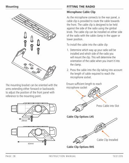
Mounting
The mounting bracket can be oriented with the arms extending either forward or backwards to adjust the position of the front panel with reference to the mounting point.
29mm
63mm
FITTING THE RADIO
Microphone Cable Clip
As the microphone connects to the rear panel, a cable clip is provided to route the cable towards the front. The cable clip is designed to be held against the side of the radio using the gimbal knob. The cable clip can be installed on either side of the radio with the cable clamp in the upper or lower position.
To install the cable into the cable clip
1. Determine which way up your radio will be installed and which side of the radio you will mount the clip. This will determine the orientation of the cable when you insert it into the clamp.
2. Press the cable into the clip taking into account the length of cable required to reach the microphone socket.
Cable Clip Options LHS
Cable Clip Options RHS
Cable Clip Installed
Ensure sufficient length to reach microphone socket
Press Cable into Slot

T X 3 1 2 0 S I N S T R U C T I O N M A N UA L PA G E 2 9
Gimbal KnobGimbal Knob
If using the mounting bracket, fi t radio into the bracket and insert the cable clip at the required location. Install the gimbal knobs and tighten.
If not using the mounting bracket, place the cable clip in the required location and insert the plastic collar provided. Secure the assembly using the gimbal knob and tighten.The radio can now be fi xed directly to a fl at surface using Velcro or tape.
Mounting Bracket
Microphone Cable Clip Plug Microphone Plug into Socket on Rear Panel
Microphone Cable
Gimbal Knob
Collar
Plug Microphone Plug into Socket on Rear Panel
Gimbal Knob
Microphone Cable Clip

PA G E 3 0 I N S T R U C T I O N M A N UA L T X 3 1 2 0 S
FLIPPING THE DISPLAY
The TX3120S’s small size allows it to be mounted in almost any convenient location. However the most suitable location may sometimes require the unit to be installed upside-down when referenced to your driving position. The TX3120S is designed to overcome this situation by allowing the display to be ‘flipped’ so that it can be read in either orientation. In addition the keys have symbols that can also be read in either orientation.
To flip the display, please see the section ‘Flipping the Display’ described under ‘General Operation’.
ANTENNA CONNECTION
It is essential to select a good quality, high efficiency, 477 MHz antenna. A poor quality antenna or one not designed for the specific frequency band you are using will give very poor performance.
GME have a wide range of suitable 477 MHz UHF CB antennas to suit most installations and applications. We recommend contacting your local GME retailer for advice.
The antenna socket on the TX3120S is an FME type. If your antenna cable uses a PL259 connector, connect it to your TX3120S using the supplied FME adaptor.
FME Antenna Socket
FME Adaptor
PL259 Antenna Plug
DC Connector

T X 3 1 2 0 S I N S T R U C T I O N M A N UA L PA G E 3 1
MICROPHONE CONNECTION
The TX3120S is supplied with a speaker microphone which has a built-in speaker to supplement the speaker inside the radio when operating in noisy environments. The speaker microphone has a 2 pin connector that plugs into the dual socket on the radio’s rear panel.
Microphone Plug
NOTE: The radio’s internal speaker can be switched off if required (via the menu) so that the sound is heard only from the speaker microphone.
WIRING
DC POWER CONNECTION
The radio is designed for 13.8 volt DC, negative earth installations only (i.e. where the negative terminal of the battery is connected to the chassis or frame of the vehicle). There are two recommended methods of installation.
Radio remains ON when ignition switch is OFF
RED
BLACK
ChassisCar battery
Ignition Switch
Radio turns ON and OFF with ignition switch
RED
BLACK
ChassisCar battery
Ignition Switch
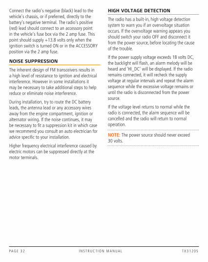
Connect the radio’s negative (black) lead to the vehicle’s chassis, or if preferred, directly to the battery’s negative terminal. The radio’s positive (red) lead should be connected via the 2 amp fuse to the battery’s positive terminal.
Alternatively, the positive lead could be connected into the fuse box at a point that has +13.8 volts continuously available (on the battery side of the ignition switch) via the 2 amp fuse.
Radio remains ON when ignition switch is OFF
RED
BLACK
ChassisCar battery
Ignition Switch
Radio turns ON and OFF with ignition switch
RED
BLACK
ChassisCar battery
Ignition Switch
PA G E 3 2 I N S T R U C T I O N M A N UA L T X 3 1 2 0 S
Connect the radio’s negative (black) lead to the vehicle’s chassis, or if preferred, directly to the battery’s negative terminal. The radio’s positive (red) lead should connect to an accessory point in the vehicle’s fuse box via the 2 amp fuse. This point should supply +13.8 volts only when the ignition switch is turned ON or in the ACCESSORY position via the 2 amp fuse.
NOISE SUPPRESSION
The inherent design of FM transceivers results in a high level of resistance to ignition and electrical interference. However in some installations it may be necessary to take additional steps to help reduce or eliminate noise interference.
During installation, try to route the DC battery leads, the antenna lead or any accessory wires away from the engine compartment, ignition or alternator wiring. If the noise continues, it may be necessary to fit a suppression kit in which case we recommend you consult an auto electrician for advice specific to your installation.
Higher frequency electrical interference caused by electric motors can be suppressed directly at the motor terminals.
HIGH VOLTAGE DETECTION
The radio has a built-in, high voltage detection system to warn you if an overvoltage situation occurs. If the overvoltage warning appears you should switch your radio OFF and disconnect it from the power source, before locating the cause of the trouble.
If the power supply voltage exceeds 18 volts DC, the backlight will flash, an alarm melody will be heard and ‘HI_DC’ will be displayed. If the radio remains connected, it will recheck the supply voltage at regular intervals and repeat the alarm sequence while the excessive voltage remains or until the radio is disconnected from the power source.
If the voltage level returns to normal while the radio is connected, the alarm sequence will be cancelled and the radio will return to normal operation.
NOTE: The power source should never exceed 30 volts.
T X 3 1 2 0 S I N S T R U C T I O N M A N UA L PA G E 3 3
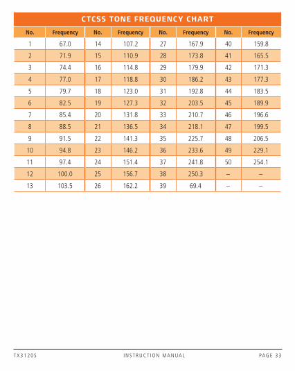
CTCSS TONE FREQUENCY CHART
No. Frequency No. Frequency No. Frequency No. Frequency
1 67.0 14 107.2 27 167.9 40 159.8
2 71.9 15 110.9 28 173.8 41 165.5
3 74.4 16 114.8 29 179.9 42 171.3
4 77.0 17 118.8 30 186.2 43 177.3
5 79.7 18 123.0 31 192.8 44 183.5
6 82.5 19 127.3 32 203.5 45 189.9
7 85.4 20 131.8 33 210.7 46 196.6
8 88.5 21 136.5 34 218.1 47 199.5
9 91.5 22 141.3 35 225.7 48 206.5
10 94.8 23 146.2 36 233.6 49 229.1
11 97.4 24 151.4 37 241.8 50 254.1
12 100.0 25 156.7 38 250.3 – –
13 103.5 26 162.2 39 69.4 – –

PA G E 3 4 I N S T R U C T I O N M A N UA L T X 3 1 2 0 S
DSC CODE CHART
DCS CODE DCS CODE DCS CODE DCS CODE DCS CODE DCS CODE
1 023 19 116 37 225 55 325 73 452 91 627
2 025 20 122 38 226 56 331 74 454 92 631
3 026 21 125 39 243 57 332 75 455 93 632
4 031 22 131 40 244 58 343 76 462 94 654
5 032 23 132 41 245 59 346 77 464 95 662
6 036 24 134 42 246 60 351 78 465 96 664
7 043 25 143 43 251 61 356 79 466 97 703
8 047 26 145 44 252 62 364 80 503 98 712
9 051 27 152 45 255 63 365 81 506 99 723
10 053 28 155 46 261 64 371 82 516 100 731
11 054 29 156 47 263 65 411 83 523 101 732
12 065 30 162 48 265 66 412 84 526 102 734
13 071 31 165 49 266 67 413 85 532 103 743
14 072 32 172 50 271 68 423 86 546 104 754
15 073 33 174 51 274 69 431 87 565 - -
16 074 34 205 52 306 70 432 88 606
17 114 35 212 53 311 71 445 89 612 - -
18 115 36 223 54 315 72 446 90 624 - -

T X 3 1 2 0 S I N S T R U C T I O N M A N UA L PA G E 3 5
UHF CB OPERATING FREQUENCIES
CH Frequency (MHz) CH Frequency (MHz) CH Frequency (MHz) CH Frequency (MHz)
1 476.425 21 476.925 41 476.4375 61 476.9375
2 476.450 22 476.950 42 476.4625 62 476.9625
3 476.475 23 476.975 43 476.4875 63 476.9875
4 476.500 24 477.000 44 476.5125 64 477.0125
5 476.525 25 477.025 45 476.5375 65 477.0375
6 476.550 26 477.050 46 476.5625 66 477.0625
7 476.575 27 477.075 47 476.5875 67 477.0875
8 476.600 28 477.100 48 476.6125 68 477.1125
9 476.625 29 477.125 49 476.6375 69 477.1375
10 476.650 30 477.150 50 476.6625 70 477.1625
11 476.675 31 477.175 51 476.6875 71 477.1875
12 476.700 32 477.200 52 476.7125 72 477.2125
13 476.725 33 477.225 53 476.7375 73 477. 2375
14 476.750 34 477.250 54 476.7625 74 477.2625
15 476.775 35 477.275 55 476.7875 75 477.2875
16 476.800 36 477.300 56 476.8125 76 477.3125
17 476.825 37 477.325 57 476.8375 77 477.3375
18 476.850 38 477.350 58 476.8625 78 477.3625
19 476.875 39 477.375 59 476.8875 79 477.3875
20 476.900 40 477.400 60 476.9125 80 477.4125
Repeater output channels (Duplex)
11 Officially designated call channel
40 Road channel
18 Caravan and motor-home
10 4WD / Off-road
Emergency use only
Telemetry / SelCall use only. Voice transmission is inhibited as required by AS/NZS 4365.2011
Guard band channel. Transmission is inhibited as required by AS/NZ 4365:2011
Repeater input channels (Duplex)

PA G E 3 6 I N S T R U C T I O N M A N UA L T X 3 1 2 0 S
SPECIFICATIONS
ENVIRONMENTAL
Temperature Range: -10°C to +60°C
ELECTRICAL
GENERAL
Compliant Specification: AS/NZS 4365:2011 Frequency Range: 476.425 – 477.4125 MHz Number of Channels: 80 UHF CB Channel Spacing: 12.5 kHz Operation Mode: Simplex channels 1-80 Semi duplex channels 1–8, 41–48. Scanning Speed: 20 channels per second Antenna Impedance: 50 Ohms nominal Operating Voltage Range: 10-15 volts DC Nominal Battery Voltage: 13.8 volts DC Over Voltage Protection: 25 volts DC max At 18 volts DC the RF power is reduced, and the words ‘Hi DC’ flash. Over Current Protection: In-line 2A Fuse Reverse Polarity Protection: Shunt Diode
TRANSMITTER
RF Output: 5.0 watts max Modulation: FM Maximum Deviation: < ± 2.5 kHz at + 20 dB limiting Spurious Emissions: < -70 dBc Transmit Frequency Response: +6 dB per octave 300 Hz to 3 kHz +1-3 dB Audio Signal to Noise: > 45 dB Current Consumption: 1.5 amps with 50 Ohms termination Frequency Stability: ±2.5 PPM

T X 3 1 2 0 S I N S T R U C T I O N M A N UA L PA G E 3 7
Specifications are subject to change without notice or obligation
RECEIVER
Circuit Type: Double Conversion Superheterodyne Intermediate Frequencies: 1st – 38.85 MHz 2nd – 450 kHz Current Consumption: < 180 mA muted 600 mA @ max. A.F output Sensitivity: 123 dBm for 12 dB SINAD unweighted Selectivity: -6 dB at + 3.5 kHz -60 dB at ± 12.5 kHz Intermodulation Immunity: 73 dB Blocking Immunity: 100 dB Spurious Response Immunity: 70 dB Audio Power: 3 watts average into 4 Ohms Audio Signal to Noise: > 45 dB Receive Frequency Response: -6 dB/Octave de-emphasis 300 Hz to 3 kHz + 1-3 dB Conducted Spurious Emission: < -57 dBm
MECHANICAL
Dimensions: 102 (W) x 97 (D) x 23 (H) mm Weight: 178 grams Shock and Vibration: MIL STD 810 method

PA G E 3 8 I N S T R U C T I O N M A N UA L T X 3 1 2 0 S
STANDARD COMMUNICATIONS WARRANTY AGAINST DEFECTS
This warranty against defects is given by Standard Communications Pty Ltd ACN 000 346 814 (We, us, our or GME). Our contact details are set out in clause 2.7.
1. Consumer guarantees
1.1 Our goods come with guarantees that cannot be excluded under the Australian Consumer Law. You are entitled to a replacement or refund for a major failure and for compensation for any other reasonably foreseeable loss or damage. You are also entitled to have the goods repaired or replaced if the goods fail to be of acceptable quality and the failure does not amount to a major failure.
1.2 To the extent we are able, we exclude all other conditions, warranties and obligations which would otherwise be implied.
2. Warranty against defects
2.1 This warranty is in addition to and does not limit, exclude or restrict your rights under the Competition and Consumer Act 2010 (Australia) or any other mandatory protection laws that may apply.
2.2 We warrant our goods to be free from defects in materials and workmanship for the warranty period (see warranty table) from the date of original sale (or another period we agree to in writing). Subject to our obligations under clause 1.2, we will at our option, either repair or replace goods which we are satisfied are defective. We warrant any replacement parts for the remainder of the period of warranty for the goods into which they are incorporated.
2.3 To the extent permitted by law, our sole liability for breach of a condition, warranty or other obligation implied by law is limited
(a) in the case of goods we supply, to any one of the following as we decide –
(i) the replacement of the goods or the supply of equivalent goods;
(ii) the repair of the goods;
(iii) the cost of repairing the goods or of acquiring equivalent goods;
(b) in the case of services we supply, to any one of the following as we decide –
(i) the supplying of the services again;
(ii) the cost of having the services supplied again.
2.4 For repairs outside the warranty period, we warrant our repairs to be free from defects in materials and workmanship for three months from the date of the original repair. We agree to re-repair or replace (at our option) any materials or workmanship which we are satisfied are defective.
2.5 We warrant that we will perform services with reasonable care and skill and agree to investigate any complaint regarding our services made in good faith. If we are satisfied that the complaint is justified, and as our sole liability to you under this warranty (to the extent permitted at law), we agree to supply those services again at no extra charge to you.
2.6 To make a warranty claim you must before the end of the applicable warranty period (see warranty table), at your own cost, return the goods you allege are defective, provide written details of the defect, and give us an original or copy of the sales invoice or some other evidence showing details of the transaction.

T X 3 1 2 0 S I N S T R U C T I O N M A N UA L PA G E 3 9
2.7 Send your claim to: Standard Communications Pty Ltd. PO Box 96 Winston Hills, NSW 2153, Australia. Tel: (02) 8867 6000 Fax: (02) 8867 6199 Email: [email protected]
2.8 If we determine that your goods are defective, we will pay for the cost of returning the repaired or replaced goods to you, and reimburse you for your reasonable expenses of sending your warranty claim to us.
3. What this warranty does not cover
3.1 This warranty will not apply in relation to:
(a) goods modified or altered in any way;
(b) defects and damage caused by use with non Standard Communications products;
(c)) repairs performed other than by our authorised representative;
(d)) defects or damage resulting from misuse, accident, impact or neglect;
(e)) goods improperly installed or used in a manner contrary to the relevant instruction manual; or
(f)) goods where the serial number has been removed or made illegal.
4. Warranty period
4.1 We provide the following warranty on GME and Kingray products. No repair or replacement during the warranty period will renew or extend the warranty period past the period from original date of purchase.
PRODUCT TYPE WARRANTY PERIOD
477 MHz UHF CB mobile radio 5 years
Part Number: 311029 Drawing Number: 49382-2 PAGE 40
For more information call or visit us:
A division of Standard Communications Pty Ltd.Head Office: PO Box 96, Winston Hills, NSW 2153, Australia.New Zealand: PO Box 58446 Botany, Auckland, 2163, NZ. T: (09) 274 0955.All international enquiries email: [email protected]