uhf cb transceiver i410pro - everything in radio · band radio stations) ... the user of this uhf...
TRANSCRIPT
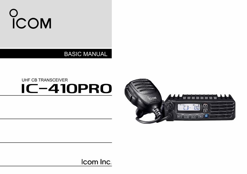
BASIC MANUAL
i410PROUHF CB TRANSCEIVER

i
IMPORTANTREAD ALL INSTRUCTIONS carefully before using the IC-410PRO uhf cb transceiver.KEEP THIS BASIC MANUAL, as it contains important operating information that may be useful in the future.
You can download the ADVANCED MANUAL for more information from the Icom website.(http://www.icom.co.jp/world/support/download/manual/index.php)
Icom, Icom Inc. and the Icom logo are registered trademarks of Icom Incorporated (Japan) in Japan, the United States, the United Kingdom, Germany, France, Spain, Russia, Australia, New Zealand and/or other countries.
i. The use of the citizen band radio service is licenced in Australia by the ACMA Radiocommunications (Citizens Band Radio Stations) Class Licence and in New Zealand by the Ministry of Economic Development (MED) General User Radio Licence for Citizen Band Radio and operation is subject to conditions contained within these licences.
ii. Always listen on a channel (or observe the channel busy indicator) to ensure it is not already being used before transmitting.
iii. In Australia, channel 11 is the customary calling channel for establishing communication. Channel 40 is the customary road vehicle channel.
iv. In Australia, except in an emergency, a CB transmitter shall not be operated on UHF emergency channels 5 and 35.
v. No voice transmissions are permitted on data channels 22 and 23 (voice operation is inhibited on these channels).
vi. The user of this UHF CB communications device shall not transmit Selcall tones for longer than 3 seconds during any 60 second period.
vii. UHF CB repeaters extend the operational range of your radio. Repeaters operate utilising two channels (repeater input/repeater output). It is important to avoid operation on locally used repeater input channels (in the channel range of 31 to 38 and 71 to 78) or locally used repeater output channels (in the channel range of 1 to 8 and 41 to 48), unless long distance communication via the repeater is specifically required. See the section on repeater operation (ADVANCED MANUAL) for more information.
viii Please be aware that the UHF CB network may experience possible operational issues during the changeover to narrowband. This transceiver operates on 12.5 kHz channel spacing. During the changeover period from 25 kHz to 12.5 kHz spacing, there may be some loss of quality when 12.5 kHz (narrowband, 2.5 kHz deviation) transmissions are received on 25 kHz (wide band, 5.0 kHz deviation) equipment, and vice-versa. There may also be interference due to older equipment being operated on channels adjacent to new narrowband channels, as the channel setting on these may cause some ‘overlap’. A list of currently authorised channels can be found on the ACMA website (Australia) and on the MED website in New Zealand.
GENERAL INFORMATION

ii
PRECAUTIONSR WARNING! NEVER connect the transceiver to an AC outlet. This may pose a fire hazard or result in an electric shock.R WARNING! NEVER operate or touch the transceiver and microphone with wet hands. This may result in an electric shock or damage the transceiver and microphone.R WARNING! NEVER connect the transceiver to a power source of more than 16 V DC. This could cause a fire or damage the transceiver.R WARNING! NEVER connect the transceiver to a power source using reverse polarity. This will damage the transceiver.
EXPLICIT DEFINITIONSWORD DEFINITION
RDANGER! Personal death, serious injury or an explosion may occur.
RWARNING! Personal injury, fire hazard or electric shock may occur.
CAUTION Equipment damage may occur.
NOTEIf disregarded, inconvenience only. No risk of personal injury, fire or electric shock.
R WARNING! NEVER cut the DC power cable between the DC plug and fuse holder. If an incorrect connection is made after cutting, the transceiver may be damaged.R WARNING! NEVER place the transceiver where normal operation of the vehicle may be hindered or where it could cause bodily injury.CAUTION: NEVER expose the transceiver and microphone to rain, snow or any liquids. The transceiver and microphone may be damaged.DO NOT push the PTT when not actually intending to transmit.DO NOT allow children to play with any transceiver equipment containing a transmitter.DO NOT operate the transceiver near unshielded electrical blasting caps or in an explosive atmosphere.DO NOT operate the transceiver for extended periods without running the vehicle’s engine. The transceiver’s power consumption may soon exhaust the vehicles battery.DO NOT set the transceiver in a place without adequate ventilation. Heat dissipation may be affected, and the transceiver may be damaged.DO NOT use harsh solvents such as benzine or alcohol to clean the transceiver, as they will damage the transceiver’s surfaces. If the transceiver becomes dusty or dirty, wipe it clean with a soft, dry cloth.
iii
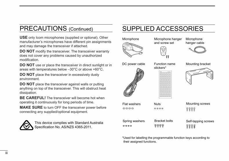
PRECAUTIONS (Continued) SUPPLIED ACCESSORIES
This device complies with Standard Australia Specification No. AS/NZS 4365-2011.
Microphone Microphone hanger and screw set
Microphone hanger cable
DC power cable
Flat washers
Spring washers Bracket bolts
Mounting screws
Self-tapping screws
Nuts
Mounting bracketFunction name stickers*
USE only Icom microphones (supplied or optional). Other manufacturer’s microphones have different pin assignments and may damage the transceiver if attached.DO NOT modify the transceiver. The transceiver warranty does not cover any problems caused by unauthorized modification.DO NOT use or place the transceiver in direct sunlight or in areas with temperatures below –30°C or above +60°C. DO NOT place the transceiver in excessively dusty environment.DO NOT place the transceiver against walls or putting anything on top of the transceiver. This will obstruct heat dissipation.BE CAREFUL! The transceiver will become hot when operating it continuously for long periods of time.MAKE SURE to turn OFF the transceiver power before connecting any supplied/optional equipment.
* Used for labelling the programmable function keys according to their assigned functions.

iv
TABLE OF CONTENTSIMPORTANT .......................................................................... iGENERAL INFORMATION .................................................... iEXPLICIT DEFINITIONS ...................................................... iiPRECAUTIONS .................................................................... iiSUPPLIED ACCESSORIES .................................................iii
1. PANEL DESCRIPTION ................................................1–3 ■ Front panel ...................................................................1 ■ Function display ...........................................................3
2. BASIC OPERATION ........................................................4 ■ Receiving and Transmitting ..........................................4
3. SET MODE .......................................................................5 ■ Using the Set mode .....................................................5 ■ Set mode item list ........................................................5
4. OPTIONS .........................................................................6
5. WARRANTY AND REGISTRATION ............................7–9
6. TROUBLESHOOTING ...................................................10
INDEX................................................................................. 11

1
1 PANEL DESCRIPTION
q w SpeakerFunction display (p. 3) e
tyui r
q VOLUME CONTROL KNOB Adjusts the audio output level.w UP/DOWN KEYS [UP]/[DOWN]* * Different functions may be assigned by your dealer. Push to select an operating channel, select an option in
the Set mode items, and so on.e POWER KEY [ ] Push to turn the transceiver ON or OFF.
r [FUNC] KEY* * Different functions may be assigned by your dealer. Push to change between Normal mode and Function
mode. Normal mode ➥ Hold down for 2 seconds to enter the Set mode (p. 5). Function mode ➥ Hold down for 2 seconds to enter the Zone Selection
mode.
■ Front panel

u [MONI] KEY* * Different functions may be assigned by your dealer.
Normal mode ➥ Push to turn the Monitor (open squelch) function ON
or OFF. ➥ Hold down for 2 seconds to activate the following
functions in sequential order.
Function mode ➥ Push to turn the ATS (Automatic Transponder System)
function ON or OFF. ➥ Hold down for 2 seconds to transmit a Smart ring
signal.i MICROPHONE CONNECTOR Connects the supplied or an optional microphone.
2
1PANEL DESCRIPTION
12345678910111213141516
t [DUP] KEY* * Different functions may be assigned by your dealer.
Normal mode ➥ Push to select the Duplex (repeater access) and
Simplex (no repeater access) mode. ➥ Hold down for 2 seconds to electronically lock all keys
except [DUP], [FUNC], and [MONI]. ➥ Hold down for 2 seconds again to unlock all keys. Function mode ➥ Push to select the Priority channel, if set. ➥ Hold down for 2 seconds to set the selected channel
as the Priority channel. ➥ Hold down for 2 seconds again to return the Priority
channel to a Normal channel.y [SCAN] KEY* * Different functions may be assigned by your dealer. Normal mode ➥ Push to start or stop a scan. ➥ Hold down for 2 seconds to tag or untag the displayed
channel. The tagged channels will be scanned. Function mode ➥ Push to enter the Selcall Code Channel Selection
mode. ➥ Hold down for 2 seconds to transmit the selected
Selcall code, when a CB channel is selected.
TSQL(Tone squelch)
Only receives calls with the same tone squelch code.
TSQL ë(Pocket beep) Pocket beep function is ON.
(No tone operation) “TSQL ë” disappears.
3
1 PANEL DESCRIPTION
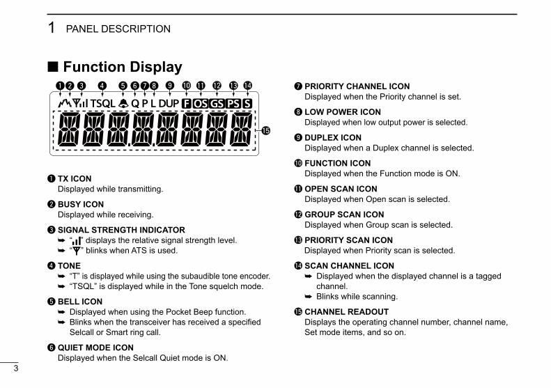
■ Function Display
q TX ICON Displayed while transmitting.
w BUSY ICON Displayed while receiving.
e SIGNAL STRENGTH INDICATOR ➥ “ ” displays the relative signal strength level. ➥ “ ” blinks when ATS is used.
r TONE ➥ “T” is displayed while using the subaudible tone encoder. ➥ “TSQL” is displayed while in the Tone squelch mode.
t BELL ICON ➥ Displayed when using the Pocket Beep function. ➥ Blinks when the transceiver has received a specified
Selcall or Smart ring call.
y QUIET MODE ICON Displayed when the Selcall Quiet mode is ON.
u PRIORITY CHANNEL ICON Displayed when the Priority channel is set.
i LOW POWER ICON Displayed when low output power is selected.
o DUPLEX ICON Displayed when a Duplex channel is selected.
!0 FUNCTION ICON Displayed when the Function mode is ON.
!1 OPEN SCAN ICON Displayed when Open scan is selected.
!2 GROUP SCAN ICON Displayed when Group scan is selected.
!3 PRIORITY SCAN ICON Displayed when Priority scan is selected.
!4 SCAN CHANNEL ICON ➥ Displayed when the displayed channel is a tagged
channel. ➥ Blinks while scanning.
!5 CHANNEL READOUT Displays the operating channel number, channel name,
Set mode items, and so on.
qw e r t yui
!5
o !0 !1 !2 !3 !4

4
2BASIC OPERATION
12345678910111213141516
■ Receiving and transmittingNOTE: Transmitting without an antenna may damage the transceiver.
1. Receiving
If “TSQL” or “TSQL ë” is displayed, you can only receive calls from others with the same tone squelch code.
Select the desired operating channel. ➥ Push [UP]/[DOWN]. • Push [MONI] to turn the Monitor function ON or OFF.
2. Transmitting
1) Check for a clear channel, or wait until a conversation is completed before transmitting.
2) While holding down [PTT], speak into the microphone at your normal voice level.
InformationTo maximise the clarity of the signal:• Pause briefly after pushing [PTT]. This ensures that the first part of
your message is transmitted.• Hold the microphone about 5 to 10 cm from your mouth.
Transmit inhibit functionThe transceiver will not transmit under the following conditions.• The channel is busy.• The displayed channel is a receive only channel. (Example: CB22, CB23)
Output power level Depending on the operating environment, it is useful to reduce or increase the transceiver output power level of the transceiver. 1) Enter the Set mode. ➥ Hold down [FUNC] for 2 seconds.2) Select the “RFPOW” menu. ➥ Push [FUNC] until the “RFPOW” menu is displayed.3) Select “HI” or “Lo.” ➥ Push [UP]/[DOWN].4) Exit the Set mode. ➥ Hold down [FUNC] for 2 seconds.
5
3 SET MODE
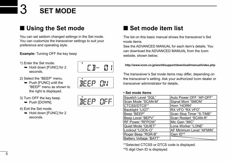
■ Using the Set modeYou can set seldom changed settings in the Set mode. You can customize the transceiver settings to suit your preference and operating style.
Example: Turning OFF the key beep
■ Set mode item listThe list on this basic manual shows the transceiver’s Set mode items.See the ADVANCED MANUAL for each item’s details. You can download the ADVANCED MANUAL from the Icom website, shown below.
http://www.icom.co.jp/world/support/download/manual/index.php
The transceiver’s Set mode items may differ, depending on the transceiver’s setting. Ask your authorized Icom dealer or transceiver administrator for details.
• Set mode itemsSquelch Level “SQL” Auto Power OFF “AP-OFF”Scan Mode “SCAN-M” Signal Moni “SMON”CTCSS/DTCS*1 Horn “HORN”Backlight “LIGT” RX VFO “RX VFO”Beep “BEEP” Scan Stop Timer “S-TIME”Beep Level “BEPV” Scan Restart “SCAN-R”RF Power “RFPOW” Mic Gain “MIC”Quiet Mode “QUIET” Lone Worker “LONE”Lockout “LOCK-O” AF Minimum Level “AFMIN”Roger Beep “RGR-B” Own ID*2
Battery Voltage “BATT”
*1Selected CTCSS or DTCS code is displayed. *25 digit Own ID is displayed.
1) Enter the Set mode. ➥ Hold down [FUNC] for 2
seconds.
2) Select the “BEEP” menu. ➥ Push [FUNC] until the
“BEEP” menu as shown to the right is displayed.
3) Turn OFF the key beep. ➥ Push [DOWN].
4) Exit the Set mode. ➥ Hold down [FUNC] for 2
seconds.

D MICROPHONES• HM-211 noise canceling microphone• HM-152T dtmf microphone Hand microphone with a DTMF keypad.
• SM-26 desktop microphone Desktop microphone with a monitor switch.
D SPEAKERS• SP-35 external speaker External speaker with a 2 meter cable.• SP-35L external speaker External speaker with a 6 meter cable.
DOTHERS• OPC-1939 acc cable• CS-410PRO cloning software + OPC-1122U cloning cable Enables quick and easy entry of settings such as RX
frequencies and Set mode contents.
Approved Icom optional equipment is designed for optimal performance when used with an Icom transceiver.Icom is not responsible for the destruction or damage to an Icom transceiver in the event the Icom transceiver is used with equipment that is not manufactured or approved by Icom.
6
4OPTIONS
12345678910111213141516

7
5 WARRANTY AND REGISTRATION
ICOM LIMITED WARRANTYIcom Incorporated is proud of its advanced technology and the high quality of workmanship and components included in the production of every product. Our goods come with guarantees that cannot be excluded under the Australian Consumer Law. You are entitled to a replacement or refund for a major failure and for compensation for any other reasonably foreseeable loss or damage. You are also entitled to have the goods repaired or replaced if the goods fail to be of acceptable quality and the failure does not amount to a major failure.Icom (Australia) Pty. Ltd., the authorised Icom Distributor, warrants this Icom product within Australia to be free from defects in material or workmanship for the applicable period indicated below:
• Radios: Five (5) years from the date of purchase, (excluding accessories), when
purchased from an Australian authorised Icom Dealer.• Accessories: One (1) year from the date of purchase, when purchased from an
Australian authorised Icom Dealer. (i.e. battery, antenna, battery chargers etc)
Icom (Australia) Pty. Ltd. will, at its discretion, and subject to the terms and conditions stated below, repair or replace any goods or component parts which after examination are found to be defective.Unless otherwise expressly provided, any fault arising from defective workmanship or material shall be rectified by Icom where the equipment is returned freight prepaid to Icom (Australia) Attn: Service Dept. Unit 1/103 Garden Rd, Clayton, VIC, 3168.Telephone (03) 9549 7500, Fax: (03) 9549 7505. Email [email protected].
This warranty shall not apply:(a) To an Icom Product which has failed due to improper installation,
misuse, accident, alteration or unauthorised repair or modification.(b) If any serial number or identification plate attached to the goods has
been altered, rendered illegible, or removed(c) If the goods have been damaged by corrosion, deterioration or the
like contributed to abnormal temperatures; the influence of foreign matter or energy or physical or chemical properties of water, steam or chemical compounds.
(d) To any Icom product not originally supplied by Icom (Australia) Pty Ltd to an authorised Dealer of Icom (Australia) Pty. Ltd.
Please check with us if you feel an Icom product is being offered for sale that has been sourced from other than Icom (Australia) Pty Ltd.
WARRANTY SERVICE INSTRUCTIONS If you are experiencing difficulty with your Icom equipment:1. For warranty claims, complete a repair order form located at: http://
www.icom-australia.com/files/Repair_Order_Form.pdf and send with goods to Icom (Australia) with a brief explanation of the issue.
2. If the fault is related to the use of a particular accessory or accessories, please include these for inspection with the radio, and list these on the repair order form. Icom (Australia) Pty. Ltd. shall assume no liability for the loss or safe return of an accessory item that is not listed.
3. Please contact Icom (Australia) regarding any compensation that may be payable for reasonable expenses incurred in making a warranty claim.
4. If the requested repairs or services are within the terms of warranty, your equipment will be returned after repair (prepaid) to any designated point within Australia.
5. If the requested repairs of service are not within the terms of warranty, or if you fail to provide acceptable evidence of the date of purchase, return freight will be charged.
This warranty is in addition to and does not limit, exclude or restrict your right under the Competition and Consumer Act 2010 or any other protection laws that may apply.
PRODUCT REGISTRATIONPlease log on to www.icom.net.au to register your Icom product, or complete & return the registration reply page.

PLA
CE
PO
STA
GE
HE
RE
Icom (A
ustralia) Pty. Ltd.
Unit 1/103 G
arden Road
Clayton VIC
3168
RE
GIS
TR
AT
ION
CA
RD
Ple
ase
fold
and
tape
clo
sed
Cut
her
e

Model No:
Purchaser Details:
Please provide the following optional information to help us meet your future needs:
Serial No:
Purchaser Name:
Purchaser Address:
Phone No:Email:
Magazines you regularly purchase from the Newsagent:
In what media have you seen Icom products advertised?
Date of Purchase:
Receipt No.:
P/Code :
Dealer Name:
Occupation:
Comments:
I would like more information on the following:
Other Radio Communications Equipment you use:
Thank you for completing this Registration card. We feel confident you will enjoy the many years of superior performance your Icom equipment provides.
Other:Newspaper Magazine TV Radio Website
Air Band Commercial Radios UHF CBReceiverMarineAmateur
Cut
her
e

PROBLEM POSSIBLE CAUSE SOLUTION
Cannot receive, but others can hear my transmissions.
Squelch is set too high. Reduce the squelch level in the Set mode. (p. 5)
Tone squelch (quiet reception mode) is ON. (“TSQL” is displayed)
Hold down [MONI] for 2 seconds several times until “TSQL” disappears. (p. 2)
Selcall Quiet Mode is ON.(“Q” is displayed)
Turn OFF the Quiet mode in the Set mode. (p. 5)
Can receive, but others cannot hear my transmissions.
Output power level is set to “Lo.” (“L” is displayed)
Change the output power level to “HI” in the Set mode. (p. 5)
Other stations are operating in the Tone squelch or Selcall modes.
Set the correct Tone squelch setting for the user group.
The transceiver transmits regularly, the signal strength indicator blinks, and beeps.
The ATS (Automatic Transponder System) function is ON. Push [MONI] to turn the ATS function OFF. (p. 2)
Continuous noise is heard from the speaker.
The Monitor (Open squelch) function is ON.
Push [MONI] to turn the Monitor function OFF. (p. 2)
Squelch level set too low. Increase the squelch level in the Set mode. (p. 5)
Activity on the channelCheck if the noise is also heard on other channels. If not, another station may be transmitting on that channel, or you may be receiving interference from other devices.
Buttons have no effect or do not work as expected
The Keylock function is ON. Hold down [DUP] for 2 seconds to unlock the keys. (p. 2)
The keys may have been reassigned.
Contact your authorized Icom dealer or transceiver administrator for details.
10
6TROUBLESHOOTING
12345678910111213141516
: Stands for Normal mode. : Stands for Function mode.

11
INDEX
AATS ..................................................................................2
BBasic operation .....................................................................4
DDuplex channel .....................................................................3Duplex mode ........................................................................2
EEXPLICIT DEFINITIONS ...................................................... ii
FFront panel ...........................................................................1Function display....................................................................3Function mode ......................................................................1
GGENERAL INFORMATION ................................................... iGroup scan ...........................................................................3
IIMPORTANT ......................................................................... i
KKeylock function ...................................................................2
MMonitor function ....................................................................2
NNormal channel ....................................................................2Normal mode ........................................................................1No tone operation .................................................................2
OOpen scan ............................................................................3Options .................................................................................6Output power level................................................................4
PPanel description ..................................................................1PRECAUTIONS ....................................................................iiPriority channel .....................................................................2Priority scan ..........................................................................3
RReceiving ..............................................................................4RX VFO ................................................................................5
SSelcall ..................................................................................3Selcall code ..........................................................................2Selcall Quiet mode ...............................................................3Set mode ..............................................................................5Simplex mode .......................................................................2Smart ring .............................................................................2Smart ring call.......................................................................3Squelch level ........................................................................5SUPPLIED ACCESSORIES ................................................ iii
TTone squelch ........................................................................2Tone squelch mode ..............................................................3Transmitting ..........................................................................4Troubleshooting ..................................................................10
WWarranty and registration .....................................................7
ZZone selection mode ............................................................1

12
MEMO
12345678910111213141516

13
MEMO

14
MEMO
12345678910111213141516

1-1-32 Kamiminami, Hirano-ku, Osaka 547-0003, Japan
A-7256D-1AUPrinted in Japan© 2015 Icom Inc.Printed on recycled paper with soy ink.