subsea production systems, equipment and ...the advantages of subsea systems have made subsea...
TRANSCRIPT
Guide for Classification and Certification of Subsea Production Systems, Equipment and Components
GUIDE FOR CLASSIFICATION AND CERTIFICATION OF
SUBSEA PRODUCTION SYSTEMS, EQUIPMENT AND COMPONENTS
AUGUST 2017 (Updated August 2018 – see next page)
American Bureau of Shipping Incorporated by Act of Legislature of the State of New York 1862
2017-2018 American Bureau of Shipping. All rights reserved. ABS Plaza 16855 Northchase Drive Houston, TX 77060 USA

Updates
August 2018 consolidation includes: • August 2017 version plus Corrigenda/Editorials

F o r e w o r d
Foreword The advantages of subsea systems have made subsea production a top choice for developments in many environments around the world. Innovations and improvements are being introduced that will increase the reliability and robustness of these systems, which will be used in even more developments over time.
Verification and validation plays an important role in safe and reliable operations of these subsea production systems. This Guide specifies the ABS requirements and process for Certification and Classification of subsea production systems and their associated subsystems, equipment and/or components. An optional class notation À CSS – Production is offered for a subsea production system that has been reviewed, surveyed, installed and commissioned in full compliance with the applicable sections of this Guide.
In addition, Independent third party (I3P) services that can be provided by ABS at different project phases are also described in this Guide. These are customized services based on the request of clients and could include the following:
• Design verification (design review) and design validation (survey during manufacturing)
• Installation/commissioning verification
• In-service examination
• Life extension assessment
• Decommissioning verification
Certified Verification Agent (CVA) review to meet the government requirements can be provided during design, manufacturing and installation phases for subsea risers. For safety and pollution prevention equipment (SPPE) and subsea equipment in high-pressure high-temperature (HPHT) applications, I3P services for conformance with 30 CFR 250 Subpart H and applicable BSEE requirements can also be provided.
This Guide is to be used in conjunction with other applicable ABS Rules and Guides, codes and standards as referenced therein, and applicable national regulations.
This Guide becomes effective on the first day of the month of publication.
Users are advised to check periodically on the ABS website www.eagle.org to verify that this version of this Guide is the most current.
We welcome your feedback. Comments or suggestions can be sent electronically by email to [email protected].
ABS GUIDE FOR CLASSIFICATION & CERTIFICATION OF SUBSEA PRODUCTION SYSTEMS, EQUIPMENT & COMPONENTS . 2017 iii

T a b l e o f C o n t e n t s
GUIDE FOR CLASSIFICATION AND CERTIFICATION OF
SUBSEA PRODUCTION SYSTEMS, EQUIPMENT AND COMPONENTS
CONTENTS SECTION 1 Scope and Conditions of Classification and Certification .................. 1
1 Certification ......................................................................................... 1 3 Classification (Optional) ...................................................................... 2
3.1 ABS Class Notation ......................................................................... 2 3.3 Systems Not Built Under Survey...................................................... 2
5 I3P Services ........................................................................................ 3 7 Application and Scope ........................................................................ 4
7.1 Application ....................................................................................... 4 7.3 Scope .............................................................................................. 4 7.5 Alternatives ...................................................................................... 6 7.7 New Technologies and Novel Concepts .......................................... 6 7.9 Risk Evaluations for Alternative Arrangements and Novel
Features .......................................................................................... 6 7.11 Certification and Classification Process ........................................... 6
9 Other Regulations ............................................................................... 7 9.1 International and Other Regulations ................................................ 7 9.3 Governmental Regulations .............................................................. 7
11 References .......................................................................................... 7 13 Definitions ........................................................................................... 8 15 Abbreviations .................................................................................... 13 TABLE 1 I3P Services for the Different Phases of Design,
Manufacturing, Installation/Commissioning, Operation and Decommissioning .............................................. 3
FIGURE 1 Typical Elements in a Subsea Production System ................... 5
SECTION 2 Documents to be Submitted ................................................................ 16
1 General ............................................................................................. 16 3 Design and Manufacturing Specifications ......................................... 18
3.1 Design Specification ...................................................................... 18 3.3 Manufacturing Specification ........................................................... 18
5 General Arrangement for Subsea Production System ..................... 18 7 System Level Documents to be Submitted for Review ..................... 18
iv ABS GUIDE FOR CLASSIFICATION & CERTIFICATION OF SUBSEA PRODUCTION SYSTEMS, EQUIPMENT & COMPONENTS . 2017

9 Subsystem/Equipment/Component Level Documents to be Submitted for Review ........................................................................ 19 9.1 Design Documents ........................................................................ 19 9.3 Manufacturing Documents ............................................................. 21 9.5 Installation/Commissioning Documents ......................................... 22 9.7 In-service Documents .................................................................... 22 9.9 Life Extension Documents ............................................................. 23 9.11 Decommissioning Phase (for I3P service) ..................................... 23
TABLE 1 Documents to be Submitted for Subsea Production
Systems, Subsystems, Equipment and/or Component .............................................................................. 17
SECTION 3 Requirements for Classification/Certification ................................... 24
1 General Design Considerations ........................................................ 24 1.1 Recognized Standards .................................................................. 24 1.3 Alternative Basis of Design ............................................................ 24 1.5 Risk Assessments for Subsea Production Systems ...................... 25 1.7 Design Loading Conditions ............................................................ 26 1.9 Design Load Types ....................................................................... 26
3 General Design Requirements ......................................................... 27 3.1 Design Principle and Philosophy ................................................... 27 3.3 System Requirements ................................................................... 28 3.5 Field Layout ................................................................................... 28 3.7 Materials, Welding and Nondestructive Examination .................... 28 3.9 Corrosion/Erosion Allowance ........................................................ 28 3.11 Overpressurization Protection ....................................................... 28 3.13 Loads ............................................................................................ 29 3.15 Strength ......................................................................................... 29 3.17 Fatigue/Fracture ............................................................................ 29 3.19 High-Pressure High-Temperature (HPHT) Applications ................ 29
5 Subsystem/Equipment Requirements .............................................. 29 5.1 Subsea Connectors ....................................................................... 29 5.3 Wellhead, Tree and Tubing Hanger .............................................. 29 5.5 Flowline, Jumper and Riser ........................................................... 30 5.7 HIPPS............................................................................................ 32 5.9 Manifold/PLEM/PLET and Template ............................................. 32 5.11 Injection and Service Systems ...................................................... 32 5.13 Umbilical/Flying Lead .................................................................... 32 5.15 Electrical System ........................................................................... 33 5.17 Control and Monitoring System ..................................................... 34 5.19 Capping Stack ............................................................................... 34 5.21 Flow Meters ................................................................................... 34 5.23 ROV/ROT Interfaces ..................................................................... 34 5.25 Foundations ................................................................................... 35 5.27 Subsea Protection Structures ........................................................ 35 5.29 Summary of Governing API Standards for Each
Subsystem/Equipment .................................................................. 35 5.31 Installation ..................................................................................... 36
ABS GUIDE FOR CLASSIFICATION & CERTIFICATION OF SUBSEA PRODUCTION SYSTEMS, EQUIPMENT & COMPONENTS . 2017 v

TABLE 1 Categorization of Design Loads for Subsea Production Equipment ............................................................................... 27
TABLE 2 Load Combinations ................................................................. 27 TABLE 3 Additional Applicable Standards for Subsystems/Equipment
in the Electrical System ........................................................... 33 TABLE 4 Additional Applicable Standards for Subsystems/Equipment
in the Control and Monitoring Subsystem ............................... 34 TABLE 5 Governing API Standards for Each Subsystem/Equipment ... 36
SECTION 4 Classification/Certification Process ................................................... 37
1 General ............................................................................................. 37 3 Certification and Classification Process ............................................ 37
3.1 Design Review ............................................................................... 39 3.3 ABS Survey ................................................................................... 40 3.5 Issuance of Certificates and Reports ............................................. 41 3.7 Vendor Coordination Program ....................................................... 42
TABLE 1 Codes for Certification of Subsea Production Systems,
Subsystems, Equipment and/or Components ........................ 43 FIGURE 1 ABS Classification/Certification Process .................................. 38
SECTION 5 Materials, Welding and Nondestructive Examination ....................... 55
1 Materials ............................................................................................ 55 1.1 General .......................................................................................... 55 1.3 Material Categorization .................................................................. 55 1.5 Pressurized Members .................................................................... 55 1.7 Other Load Bearing Members ....................................................... 57 1.9 Threaded Fasteners ...................................................................... 57 1.11 Sealing (Metallic and Non-Metallic) Materials ................................ 58 1.13 Corrosion and Erosion ................................................................... 60 1.15 Thermal Insulation ......................................................................... 62
3 Material Manufacturing Considerations ............................................ 62 3.1 General .......................................................................................... 62 3.3 Manufacturing Specifications ......................................................... 63 3.5 Rolled Products ............................................................................. 63 3.7 Forgings ......................................................................................... 63 3.9 Castings ......................................................................................... 64 3.11 Forming ......................................................................................... 64
5 Welding ............................................................................................. 64 5.1 General .......................................................................................... 64 5.3 Welding Procedures ...................................................................... 65 5.5 Cladding Procedures ..................................................................... 65 5.7 Filler Materials ............................................................................... 65 5.9 Welder/Welding Operator Qualification .......................................... 66 5.11 Post Weld Heat Treatment (PWHT) ............................................... 66
vi ABS GUIDE FOR CLASSIFICATION & CERTIFICATION OF SUBSEA PRODUCTION SYSTEMS, EQUIPMENT & COMPONENTS . 2017
7 Nondestructive Examination (NDE) .................................................. 66 7.1 General.......................................................................................... 66 7.3 NDE Procedures ........................................................................... 66 7.5 Qualification of NDE Technicians .................................................. 67 7.7 Extent of Examination – Materials in Primary Product Form and
Repairs .......................................................................................... 67 7.9 Extent of Examination – Fabrication Welds and Repairs ............... 67 7.11 Time of Inspection ......................................................................... 68 7.13 Delayed Cracking Occurrences ..................................................... 68 7.15 NDT Methods and Acceptance Criteria ......................................... 69 7.17 Record Retention .......................................................................... 72
TABLE 1 Charpy Impact Testing Requirements .................................... 56 TABLE 2 Charpy Impact Testing Requirements .................................... 57 TABLE 3 Test Standards for Metallic Seals ........................................... 59 TABLE 4 Test Standards for Nonmetallic Seals..................................... 60 TABLE 5 Nondestructive Testing (NDT) of Welds in other Load
Bearing Members .................................................................... 68 SECTION 6 Surveys ................................................................................................. 73
1 General ............................................................................................. 73 3 Surveys during Construction ............................................................. 73
3.1 Surveys at Vendor’s Plant ............................................................. 73 3.3 Surveys during Installation and Commissioning ............................ 75
5 Surveys after Construction................................................................ 78 5.1 Survey Intervals ............................................................................. 78 5.3 Notification and Availability for Survey........................................... 78 5.5 Modifications ................................................................................. 78 5.7 Damage and Repairs .................................................................... 78 5.9 Temporary Equipment ................................................................... 79 5.11 Inspection and Maintenance Records ........................................... 79 5.13 ABS Maintenance Release Notes ................................................. 79 5.15 Annual Surveys ............................................................................. 79 5.17 Special Periodical Surveys ............................................................ 80 5.19 Certification on Behalf of Coastal States ....................................... 81 5.21 Survey for Life Extension............................................................... 81
7 Surveys for Decommissioning (for I3P Service) ............................... 81 APPENDIX 1 Conformance to 30 CFR 250 Subpart H ............................................. 82
1 General ............................................................................................. 82 3 SPPE Certification and Related Services ......................................... 82
3.1 SPPE Certification and Independent Third Party Review .............. 82 3.3 ABS Services ................................................................................ 82
5 Equipment in HPHT Application ....................................................... 83 5.1 General.......................................................................................... 83 5.3 ABS Services ................................................................................ 83
TABLE 1 Document Submittal List for HPHT I3P Review ...................... 84
ABS GUIDE FOR CLASSIFICATION & CERTIFICATION OF SUBSEA PRODUCTION SYSTEMS, EQUIPMENT & COMPONENTS . 2017 vii

APPENDIX 2 Typical Codes and Standards for ABS Classification/Certification of Subsea Production Systems ........................................................... 85
APPENDIX 3 Example of Design Review Letter (DRL) ............................................ 91 APPENDIX 4 Example of Independent Review Certificate (IRC) ............................. 94 APPENDIX 5 Example of Manufacturer’s Affidavit of Compliance (MAC) ............. 97 APPENDIX 6 Example of Survey Report (SR) .......................................................... 99 APPENDIX 7 Example of Certificate of Conformity (CoC) ..................................... 101 APPENDIX 8 Example Maintenance Release Note (MRN) ..................................... 103
viii ABS GUIDE FOR CLASSIFICATION & CERTIFICATION OF SUBSEA PRODUCTION SYSTEMS, EQUIPMENT & COMPONENTS . 2017

S e c t i o n 1 : S c o p e a n d C o n d i t i o n s o f C l a s s i f i c a t i o n a n d C e r t i f i c a t i o n
S E C T I O N 1 Scope and Conditions of Classification and Certification
The general requirements for conditions of Classification and Certification are contained in the ABS Rules for Conditions of Classification – Offshore Units and Structures (Part 1). Additional requirements specific to subsea production systems are contained in this Guide.
This Guide describes the requirements and process for ABS Certification, Classification and independent third party (I3P) services for subsea production systems and their associated subsystems, equipment and/or components.
Certification typically includes design review and survey during manufacturing and may include survey during installation/commissioning for certain subsystem/equipment. Classification can be offered to subsea production systems after successful Certification and installation/commissioning verification. The continuance of the Classification of subsea production systems during their service lives is dependent on meeting the requirements contained in this Guide for periodical surveys.
In addition to Certification and Classification services, I3P services for subsea production systems, subsystems, equipment and/or components include design verification, design validation, installation/commissioning verification, in-service examination, life extension assessment and decommissioning verification. Certified Verification Agent (CVA) service to meet the government requirements can also be provided during design, manufacturing and installation phases for subsea equipment. I3P services for subsea equipment in US Outer Continental Shelf (OCS) for conformance with 30 CFR 250 Subpart H can be provided as described in Appendix 1.
The definitions of Subsea Production System, Subsea Production Subsystem, Equipment and Components as applied within this Guide are as follows:
Subsea Production System. An assemblage of equipment used for producing oil and natural gas. At a minimum, the subsea production system consists of a wellhead, a tree, electrical and control systems, a flowline and/or a riser.
Subsea Production Subsystem. Electrical systems, control systems, injection systems and service systems with/without connected equipment.
Equipment. The highest level of an assembly with a bounded function (e.g., wellhead, tree, flowline, jumper, riser, manifold, etc.).
Component. A unit in the equipment designed to serve a specific function (e.g., valve, connector, choke, etc.).
1 Certification Upon request of the Owner/Operator or Designer/Manufacturer, and where permitted by the recognized Authority, ABS will issue Certificates for subsea production systems, subsystems, equipment and/or components provided that the requirements in this Guide are met and pertinent governmental requirements are fulfilled.
The Certification service includes design review and survey during manufacturing, and ABS issuances for Certification service are:
• For design review
- Design review letter (DRL) or
- Independent review certificate (IRC) for primary pressure barrier components
ABS GUIDE FOR CLASSIFICATION & CERTIFICATION OF SUBSEA PRODUCTION SYSTEMS, EQUIPMENT & COMPONENTS . 2017 1
Section 1 Scope and Conditions of Classification and Certification
• For survey during manufacturing
- Survey report (SR) and/or
- Certificate of conformity (CoC) for primary pressure barrier components
SR and/or CoC will be issued after the installation/commissioning phase for:
• Systems/Subsystems
• Equipment: wellheads, risers, pipelines, umbilicals and high integrity pressure protection system (HIPPS)
SR and/or CoC will be issued after the manufacturing phase for:
• Equipment other than those listed above
• Components
Section 4 provides details on the Certification process and codes for certification of subsea production systems, subsystem, equipment and components. Appendices 3, 4, 6 and 7 show examples of DRL, IRC, SR, and CoC, respectively.
3 Classification (Optional) Upon request of the Owner/Operator, optional Classification services can be offered for subsea systems provided the classification requirements in this Guide are met including
i) Certification/Verification requirements in Section 2 through Subsection 6/3 for design, manufacturing, and installation phases
ii) Periodical survey requirements in Subsection 6/5 for operation phase
Classification is a life cycle process extending from design, manufacturing, installation, commissioning, and continued through service life. Product Certification can be the first step of Classification. Following installation/commissioning verification, the continuance of the Classification of subsea production systems/subsystems during their service lives is dependent on meeting the requirements contained in this Guide for periodical surveys.
3.1 ABS Class Notation Subsea production systems that have been reviewed to the satisfaction of ABS as well as built, installed and commissioned to the satisfaction of the ABS Surveyors to the full requirements of this Guide, where approved by the Committee for service under the specified design environmental conditions, may be classed and distinguished in the ABS Record by the notation À CSS – Production.
3.3 Systems Not Built Under Survey The symbol “À” (Maltese Cross) signifies that the subsea production systems were reviewed to the satisfaction of ABS as well as built, installed and commissioned to the satisfaction of the ABS Surveyors. Subsea production systems that have not been reviewed by ABS or built under ABS survey, but which are submitted for Classification, will be subjected to special consideration under the following conditions.
• The systems meet all the requirements in this Guide
• The original design documents are available for ABS review
• Manufacturer databook and material traceability are available for ABS review
• Previous Classification/Certification certificates are available
Where found satisfactory and thereafter approved by the Committee, subsea production systems may be classed and distinguished in the Record by the notation described above, but the symbol “À” signifying survey during construction will be omitted.
2 ABS GUIDE FOR CLASSIFICATION & CERTIFICATION OF SUBSEA PRODUCTION SYSTEMS, EQUIPMENT & COMPONENTS . 2017

Section 1 Scope and Conditions of Classification and Certification
5 I3P Services I3P services are customized services based on the request of clients. Upon request, provided the requirements of this Guide and related ABS documents are met, ABS will provide independent services as follows.
• Design verification (design review) and design validation (survey during manufacturing)
• Installation/commissioning verification
• In-service examination
• Life extension assessment
• Decommissioning verification
Upon request of the client, Certified Verification Agent (CVA) service to meet government requirements can also be provided during design, manufacturing and installation phases for subsea risers. For safety and pollution prevention equipment (SPPE) and subsea equipment in high-pressure high-temperature (HPHT) applications, I3P services for conformance with 30 CFR 250 Subpart H and applicable BSEE requirements are available as detailed in Appendix 1.
ABS deliverables for these I3P services vary based on client request and scope of related services. Examples of ABS deliverables may be engineering review report/letter, survey report, CVA report, or I3P report.
The client should contact ABS for assistance in planning I3P services for their subsea production systems, subsystems, equipment and/or components.
Section 1, Table 1 lists I3P services for the different phases of design, manufacturing, installation/ commissioning, operation and decommissioning.
TABLE 1 I3P Services for the Different Phases of Design, Manufacturing, Installation/Commissioning, Operation and Decommissioning
Phase
Level
Design Manufacturing Installation/ Commissioning
Operation Decommissioning
Design Verification
Design Validation
Installation/ Commissioning
Verification
In-service Examination
Life Extension
Assessment
Decommissioning Verification
System R S R*, S S R, S R, S Subsystem R S R*, S S R, S R, S Equipment R S R*, S S R, S R, S Component R S S
Notes: R – Engineering Review
S – Survey
* – If not reviewed during design phase
Upon request of the client, ABS may grant an “Approval in Principle” (AIP) at an early conceptual design phase to assist the client in demonstrating project feasibility to its project partners and regulatory bodies. For the detailed process of AIP, reference can be made to the ABS Guidance Notes on Review and Approval of Novel Concepts.
For new designs (materials, components, equipment or systems), new processes or procedures with no prior in-service experience and/or any classification rules, statutory regulations or industry standards directly applicable to them, the ABS “New Technology Qualification” program can help clients to qualify that the new technology is able to perform intended functions in accordance with defined performance requirements. The process of this qualification program is contained in the ABS Guidance Notes on Qualifying New Technologies.
ABS GUIDE FOR CLASSIFICATION & CERTIFICATION OF SUBSEA PRODUCTION SYSTEMS, EQUIPMENT & COMPONENTS . 2017 3
Section 1 Scope and Conditions of Classification and Certification
7 Application and Scope
7.1 Application This Guide is applicable to subsea production systems, subsystems, equipment, and/or components listed in 1/7.3. This Guide is intended for use in conjunction with codes and standards listed in Appendix 2 as referred to in Section 3, as well as the latest edition of the following or other applicable ABS Rules and Guides.
• ABS Rules for Building and Classing Mobile Offshore Drilling Units (MODU Rules)
• ABS Rules for Building and Classing Steel Vessels (Steel Vessel Rules)
• ABS Rules for Building and Classing Offshore Support Vessels (OSV Rules)
• ABS Rules for Building and Classing Floating Production Installations (FPI Rules)
• ABS Rules for Building and Classing Facilities on Offshore Installations (Facilities Rules)
• ABS Guide for Building and Classing Subsea Riser Systems (Riser Guide)
• ABS Guide for Building and Classing Subsea Pipeline Systems (Pipeline Guide)
7.3 Scope This Guide covers subsea production systems, subsystems, equipment, and/or components used in connection with hydrocarbon well subsea production, completion, and workover operations.
The subsea production system includes, but is not limited to
• Wellhead, Tree and Tubing Hanger
• Flowline, Jumper and Riser
• HIPPS*
• Manifold/PLET/PLEM and Template
• Injection and Service Systems
• Umbilical/Flying Lead**
• Electrical System
• Control and Monitoring System
• Capping Stack
• Flow Meter
• Remotely Operated Vehicle (ROV)/Remotely Operated Tool (ROT) Interfaces
• Foundation
• Subsea Protection Structure Notes:
* HIPPS is part of the control and monitoring system
** Umbilical/flying lead is part of the electrical, control and monitoring system
Section 1, Figure 1 shows the typical elements in a subsea production system. Actual subsea fields may contain fewer or more elements than those shown in Section 1, Figure 1.
For a detailed list of components for each subsystem/equipment covered in this Guide, see Section 4, Table 1.
4 ABS GUIDE FOR CLASSIFICATION & CERTIFICATION OF SUBSEA PRODUCTION SYSTEMS, EQUIPMENT & COMPONENTS . 2017

FIGURE 1 Typical Elements in a Subsea Production System
Section 1
Scope and Conditions of C
lassification and Certification
A
BS
GUIDE FOR CLASSIFICATION & CERTIFICATION OF SUBSEA PRODUCTION SYSTEMS, EQUIPMENT & COMPONENTS . 2017 5

Section 1 Scope and Conditions of Classification and Certification
7.5 Alternatives 7.5.1 General
ABS is ready to consider alternative arrangements and designs which can be shown through either satisfactory service experience or a systematic analysis based on sound engineering principles, to meet the overall safety, serviceability, and design standards of the Rules and Guides.
7.5.2 National Standards i) ABS will consider special arrangements or design of subsea production systems,
subsystems, equipment and/or components which can be shown to comply with standards recognized in the country, provided that the proposed standards are not less effective.
ii) When alternate standards are proposed, comparative analyses are to be provided to demonstrate equivalent level of safety to the recognized standards as listed in this Guide and to be performed in accordance with 1/7.9.
7.7 New Technologies and Novel Concepts Subsea production systems, subsystems, equipment and/or components which contain novel design features to which the provisions of this Guide are not directly applicable may be classed/certified when approved by ABS on the basis that this Guide, insofar as applicable, has been complied with and that special consideration has been given to these aspects based on the best information available at that time. Justifications for the new or novel features can be accomplished by applying 1/7.9.
7.9 Risk Evaluations for Alternative Arrangements and Novel Features i) Risk evaluations for the justification of alternative arrangements or novel features may be applicable
either to the subsea production system as a whole, or to individual subsystems, equipment and/or components.
ii) ABS will consider the application of risk evaluations for alternative arrangements and novel features in the design of the subsea production system, subsystems, equipment and/or components, verification surveys during construction, and surveys for maintenance of Class.
iii) When applied, risk assessment techniques are to demonstrate that alternative arrangements and/or novel features provide acceptable levels of safety in line with current offshore and marine industry practice.
iv) Portions of the subsea production system or any of its subsystems, equipment and/or components not explicitly included in the risk evaluation submitted to ABS are to comply with any applicable part of the ABS Rules and Guides.
v) If any proposed alternative arrangement or novel feature affects any applicable requirements of flag and coastal State, it is the responsibility of the Owner/Operator to discuss with the applicable authorities the acceptance of alternatives based on risk evaluations.
The ABS Guidance Notes on Review and Approval of Novel Concepts, ABS Guidance Notes on Qualifying New Technologies, and ABS Guide for Risk Evaluations for the Classification of Marine-Related Facilities provide guidance to ABS clients on the preparation of a risk evaluation to demonstrate equivalency or acceptability for a proposed subsea production system design.
7.11 Certification and Classification Process 7.11.1 Certification Process
i) Section 4 provides the ABS Classification/Certification process for subsea production systems, subsystem, equipment, and components. Subsequently, Section 4, Table 1 identifies the typical subsea production systems, subsystems, equipment, and/or components that are part of the ABS Classification/Certification process.
ii) Related subsea production systems, subsystems, equipment and component drawings, calculations and documentation are required to be submitted to ABS by entities as listed in Section 2 to substantiate that the design of the systems, subsystems, equipment and/or components are in compliance with this Guide, and applicable codes or standards, as listed in this Guide.
6 ABS GUIDE FOR CLASSIFICATION & CERTIFICATION OF SUBSEA PRODUCTION SYSTEMS, EQUIPMENT & COMPONENTS . 2017

Section 1 Scope and Conditions of Classification and Certification
iii) Upon satisfactory completion of ABS review of design documents, ABS Engineers will issue an ABS review letter and/or an Independent Review Certificate (IRC), as specified in Section 4, Table 1. This letter or IRC, in conjunction with ABS-approved documentation, will be used and referenced during surveys.
iv) Upon satisfactory completion of survey, ABS Surveyors will issue appropriate survey reports.
7.11.2 Classification Process See Items i) through iv) above and the following.
v) Upon satisfactory completion of all of the required engineering design review and survey processes (inspection, testing, installation and commissioning), ABS may issue a Classification Certificate to the subsea production systems.
9 Other Regulations
9.1 International and Other Regulations i) This Guide covers the requirements for the Classification/Certification of subsea production systems,
subsystems, equipment, and/or components In addition, Owner/Operators, designers and builders are directed to the regulations of international, governmental and other authorities addressing those requirements in addition to or over and above the Classification/Certification requirements.
ii) Where authorized by the Administration of a country signatory thereto and upon request of the Owner/Operator of a classed subsea production system or one intended to be classed/certified, ABS will survey for compliance with the provisions of International and Governmental Conventions and Codes, as applicable.
9.3 Governmental Regulations Where authorized by a government agency and upon request of the Owner/Operator of a new or existing subsea production system, ABS will survey and class/certify subsea production systems, their associated subsystems, equipment and/or components for compliance with particular regulations of that government on their behalf.
11 References In addition to the ABS Rules and Guides denoted in 1/7.1, and codes and standards in Appendix 2, additional references can be made to the following:
• ABS Rules for Building and Classing Offshore Installations (Offshore Installations Rules)
• ABS Guide for Buckling and Ultimate Strength Assessment for Offshore Structures
• ABS Guide for Certification of Lifting Appliances (Lifting Appliances Guide)
• ABS Guide for Nondestructive Inspection of Hull Welds (NDI Guide)
• ABS Guide for Remote Control and Monitoring for Auxiliary Machinery and Systems (other than Propulsion) on Offshore Installations
• ABS Guide for Risk Evaluations for the Classification of Marine-Related Facilities
• ABS Guide for Surveys Based on Machinery Reliability and Maintenance Techniques
• ABS Guide for Surveys Using Risk-Based Inspections for the Offshore Industry
• ABS Guidance Notes on Qualifying New Technologies
• ABS Guidance Notes on Review and Approval of Novel Concepts
• ABS Guidance Notes on Risk Assessment Applications for the Marine and Offshore Oil and Gas Industries
• ABS Guidance Notes on Subsea Hybrid Riser Systems
• ABS Guidance Notes on Subsea Pipeline Route Determination
ABS GUIDE FOR CLASSIFICATION & CERTIFICATION OF SUBSEA PRODUCTION SYSTEMS, EQUIPMENT & COMPONENTS . 2017 7

Section 1 Scope and Conditions of Classification and Certification
ABS is prepared to consider other recognized codes, standards, alternative design methodology and industry practice, on a case-by-case basis, with justification as indicated in 1/7.5.
13 Definitions The following terms are used in this Guide:
Choke. A device that controls pressure and flow rate by a fixed or adjustable amount.
Barrier. An element forming part of a pressure-containing envelope that is designed to prevent unintentional flow of production/injected fluids, particularly to the external environment.
Charpy V-Notch Test: A test to reveal fracture toughness in terms of energy absorbed or lateral expansion or fracture appearance.
Client. Operator, Owner, Designer or Manufacturer.
Cluster Manifold. A structure used to support a manifold for produced or injected fluids.
Communication Distribution Unit (CDU). A unit that communicates with the host facility and distributes communication signals within the subsea network in an electrohydraulic or electric system.
Completion Riser. A temporary riser that is designed to run inside a BOP and drilling riser to allow for well completion. Completion operations are performed within the drilling riser. A completion riser can also be used for open-sea workover operations.
Completion/Workover (C/WO) Riser. A temporary riser used for completion or workover operations.
Control Path. The total distance that a control signal (e.g., electrical, optical, hydraulic) travels from the topside control system to the subsea control module (SCM) or valve actuator.
Corrosion Allowance. The amount of wall thickness added to the pipe or component to allow for corrosion, scaling, abrasion, erosion, wear and all forms of material loss.
Corrosion-Resistant Alloy (CRA). A non-ferrous alloy for which any one or the sum of the specified amount of the following alloy elements exceeds 50 %: titanium, nickel, cobalt, chromium and molybdenum.
Corrosion-Resistant Material (CRM). A ferrous or non-ferrous alloy that is more corrosion resistant than low-alloy steels.
Crack Tip Opening Displacement (CTOD). The measure of crack severity that can be compared against a critical value at the onset of crack propagation.
Depth Rating. The maximum rated working depth for a piece of equipment at a given set of operating conditions.
Design Basis. A set of project-specific design data and functional requirements that are not specified or are left open in the general standard.
Design Criteria. Quantitative formulations which describe each failure mode the conditions shall fulfil.
Design Factor. A factor (usage factor) used in working stress design.
Design Load. A combination of load effects.
Direct Hydraulic Control. A control method wherein hydraulic pressure is applied through an umbilical line to act directly on a subsea valve actuator.
Down Time. The time interval during which an item is unable to perform a required function due to a fault, or other activities (e.g., during maintenance).
Drift-Off. Unintended lateral movement of a dynamically positioned vessel off its intended location relative to the wellhead, generally caused by loss of stationkeeping control or propulsion.
Drilling Template. A multi-well template used as a drilling guide to predrill wells prior to installing a surface facility.
Driven Pile. Typically a tall steel cylindrical structure, with or without internal stiffener system, used to support subsea structures.
8 ABS GUIDE FOR CLASSIFICATION & CERTIFICATION OF SUBSEA PRODUCTION SYSTEMS, EQUIPMENT & COMPONENTS . 2017

Section 1 Scope and Conditions of Classification and Certification
Drive-Off. Unintended movement of a dynamically positioned vessel off location driven by the vessel's main propulsion or station-keeping thrusters.
Dual Redundant. Two segregated, independent components, systems, or elements, where one serves as a backup to the other; or two identical units (or systems) fulfilling the same function.
Electric Control. A control method wherein communication signals and power are conducted to the subsea system and use electric motors to open or close subsea valves.
Electrohydraulic Control. A control method wherein communication signals are conducted to the subsea system. The signals both control and operate electrically powered functions in the subsea system.
Emergency Shutdown. The controlled sequence of events ensuring that the well is secured against accidental release of hydrocarbons into the environment (i.e., closing of barrier elements).
Emergency Shutdown (ESD) System. A system of manual stations that, when activated, initiates facility shutdown.
End Fitting. The termination in a flexible pipe.
End Termination. A mechanical fitting that is attached to the end of an umbilical and that provides a means of transferring installation and operating loads, fluid and electrical services to a mating assembly mounted on the subsea facility or surface facility.
Environmental Loads. Loads due to the environment.
Export Line. A pipeline that transports processed oil and/or gas fluids between platforms or between a platform and a shore facility.
Extended Factory Acceptance Test (EFAT). A test conducted to verify that the specified requirements, for a set of interfacing products, have been fulfilled.
Factory Acceptance Test (FAT). A test conducted to verify that the specified requirements, for a product, have been fulfilled.
Fail-Safe. A term applied to equipment or a system so designed that, in the event of failure or malfunction of any part of the system, devices are automatically activated to stabilize or secure the safety of the operation.
Failure. An event causing an undesirable condition (e.g., loss of component or system function) or deterioration of functional capability to such an extent that the safety of the unit, personnel, or environment is significantly reduced
Failure Mode. The effect by which a failure is observed on the failed item [i.e., the loss of a required functionality (e.g., loss of containment)].
Fault. The state of an item characterized by inability to perform a required function, excluding the inability during preventive maintenance or other planned actions, or due to lack of external resources.
Final Element. Part of a safety instrumented system that implements the physical action necessary to achieve a safe state.
Flexible Joint. A laminated metal and elastomer assembly, having a central through-passage equal to or greater in diameter than the interfacing pipe or tubing bore, that is positioned in the riser string to reduce the local bending stresses.
Flowline. A pipeline that transports the well fluids from the wellhead to the first downstream process component.
Flowline Jumper. A length of pipe terminated by connector systems between two subsea structures.
Flying Lead. Single or multiple composite grouping of hydraulic, chemical, electrical power, electrical signal, and/or optical signal carrying conduits used to interconnect various items of subsea equipment. Flying leads may be designed for remotely operated vehicle (ROV) or remotely operated tool (ROT) assisted deployment.
Fortified Section. Piping and equipment with an intermediate pressure rating somewhere between the SIP (high) and MAWP (low) ratings.
Fracture Mechanics Assessment. Assessment and analysis where critical defect sizes under design loads are identified to determine the crack growth life (i.e., leak or fracture).
ABS GUIDE FOR CLASSIFICATION & CERTIFICATION OF SUBSEA PRODUCTION SYSTEMS, EQUIPMENT & COMPONENTS . 2017 9

Section 1 Scope and Conditions of Classification and Certification
Fracture Toughness. The property of a material that measures the resistance-to-failure resulting from crack propagation.
Functional Loads. Loads that are a consequence of the system’s existence and use without consideration of environmental or accidental effects.
Guideline. A taut line from the seafloor to the surface for the purpose of guiding equipment to the seafloor structure.
High Integrity Pressure Protection System (HIPPS). Mechanical and electrical-hydraulic SIS used to protect production assets from high-pressure upsets.
High-Pressure High-Temperature (HPHT). Refers to wells with a potential pressure greater than 103.43 MPa (15,000 psia), or with a potential temperature greater than 177°C (350°F), up to 288°C (550°F), measured at the mudline.
Horizontal Tree. A tree that does not have a production master valve in the vertical bore but in the horizontal outlets to the side.
Hydraulic Connector. A mechanical connector that is activated hydraulically.
Hydraulic Rated Working Pressure. The maximum internal pressure that the hydraulic equipment is designed to contain and/or control.
Hydrostatic Pressure. The maximum external pressure of ambient ocean environment (maximum water depth) that equipment is designed to contain and/or control.
Injection Line. A pipeline that directs liquids or gases into a formation, wellhead, or riser, to support hydrocarbon production activity (i.e., water or gas injection, gas lift, or chemical injection lines, etc.).
Inspection. The examination of an item in accordance with a specified standard.
Inspection and Test Plan. The minimum requirement of the activities for quality control and inspection agreed prior to commencement of work.
Intelligent Well Control System (IWCS). A control system used to operate an intelligent well.
Interchangeability Test (ICT). A test conducted to verify the interchangeability requirements of “identical” products, which may be interfaced with other mating products at the installation site, have been fulfilled.
Lifting Device. A tool dedicated for lifting.
Load Case: The combination of simultaneously acting loads.
Load Effect. The effect of a single load or combination of loads on the structure, such as stress, strain, deformation, displacement, or motion, etc.
Loading Conditions:
i) Normal Operation Loading Condition. Conditions which include routine operation of the subsea system and equipment.
ii) Extreme Operation Loading Condition. Conditions which include the unavoidable but predictable conditions due to the environmental and operating scenarios.
iii) Accidental/Survival Loading Condition. Conditions which include the unplanned, unavoidable, and unpredictable conditions due to the environmental, system/equipment malfunctioning, emergency operation, collision impact, abnormal environmental conditions or any other scenarios defined by operators.
iv) Temporary Loading Condition. Conditions include testing, transportation, drilling and/or completion, installation, well intervention, and decommissioning.
• Testing Condition Loading Conditions. Conditions which include hydrotesting, FAT, SIT, etc.
• Transportation Loading Condition. Conditions which include lifting/handling, load-out, etc.
• Drilling and/or Completion Loading Condition. Conditions during drilling and completion operation are to following API RP 16Q and API RP 17G, respectively.
10 ABS GUIDE FOR CLASSIFICATION & CERTIFICATION OF SUBSEA PRODUCTION SYSTEMS, EQUIPMENT & COMPONENTS . 2017

Section 1 Scope and Conditions of Classification and Certification
• Installation Loading Condition. Conditions which include deployment, abandonment and retrieval, etc.
• Well Intervention Loading Condition. Conditions during well intervention, including the loads from riser, wireline and coiled tubing etc., as defined in API RP 17G.
• Decommissioning Loading Condition. Conditions which include removal of seabed equipment.
Logic Solver. In relation to a HIPPS, a Logic Solver is the portion of an SIS that performs one or more logic function(s) related to the safety function(s).
Malfunction. Any condition of a device or an equipment item that causes it to operate improperly, but does not prevent the performance of its design function.
Manifold. The system of headers, branched piping and valves used to gather produced fluids or to distribute injected fluids in subsea oil and gas production systems.
Material Data Sheet. A document containing data regarding the physical and mechanical properties of a particular material used in the insulation process and guidelines and recommendations for its processing and use.
Maximum Allowable Working Pressure (MAWP). The highest operating pressure allowable at any point in any component other than a flowline during normal operation or static conditions.
Modular Template. A template installed as one unit or as modules assembled around a base structure (often the first well).
Mudmat. Typically a shallow structure used to support a subsea structure by distributing the load to the seabed via a structural plate or shallow skirt.
Operating Pressure. Pressure in the equipment when the plant operates at steady state condition, subject to normal variation in operating parameters.
Operating Temperature. The maximum and/or minimum temperature experienced during installation and operation of the equipment.
Pipeline. Piping that transports fluids between offshore production facilities or between a platform and a shore facility, often sub-classified into the three categories: flowlines, injection lines, and export lines.
Pipeline End Manifold (PLEM). A system of headers, piping and valves used to gather produced fluids or to distribute injected fluids in subsea production systems, generally integral to the pipeline and having more than one subsea connection.
Pipeline End Termination (PLET). A system of piping and valves, generally integral to the pipeline, used to make a subsea connection at the end of a pipeline.
Pre-Deployment Test (PDT). A test conducted to verify that the specified requirements, for a product that is ready for deployment, are still fulfilled.
Pressure-Containing. A part exposed to wellbore fluids, whose failure to function as intended results in a release of wellbore fluid to the environment.
Pressure-Controlling. A part that is intended to control or regulate the movement of pressurized fluids.
Protection Structure. The independent structure that protects subsea equipment against damage from dropped objects, fishing gear and other relevant accidental loads.
Rated Working Pressure (RWP). The maximum internal pressure that equipment is designed to contain and/or control.
Reliability. The likelihood of a given piece of safety-related equipment to remain in operation for the expected duration.
Remotely Operated Tool (ROT) System. A dedicated, unmanned, subsea tools used for installation and inspection, maintenance, and repair (IMR) tasks that require lift and/or handling capacity beyond that of free-swimming ROV systems.
ABS GUIDE FOR CLASSIFICATION & CERTIFICATION OF SUBSEA PRODUCTION SYSTEMS, EQUIPMENT & COMPONENTS . 2017 11
Section 1 Scope and Conditions of Classification and Certification
Remotely Operated Vehicle (ROV). Free-swimming or tethered submersible craft used to perform tasks such as inspection, valve operations, hydraulic functions, and other general tasks.
Rigid Jumper. A flowline jumper fabricated using steel pipe, as opposed to flexible pipe.
Riser Base. A structure that supports a marine production riser or loading terminal, and that serves as a structure through which to react to loads on the riser throughout its service life.
Room Temperature. Any temperature between 4°C and 40°C (40°F and 104°F) (i.e., temperature corresponding to the test conditions of the material).
Running Tool. A device used to run, retrieve, position or connect subsea equipment remotely from the surface.
Settlement. The permanent downward movement of a structure as a result of its own weight and other actions.
Shakedown. A phenomenon caused by cyclic loads or cyclic temperature distributions which produces plastic deformations in some regions of the component when the loading or temperature distribution is applied; but upon removal of the loading or temperature distribution, only elastic primary and secondary stresses are developed in the component, except in small areas associated with local stress (strain) concentrations.
Shutdown Valve (SDV). An automatically operated, fail closed valve used for isolating equipment.
Site Received Test (SRT). A test conducted to verify that the specified requirements, for a product that has been transported from one site to another, are still fulfilled.
Sour Service. Service conditions with H2S content exceeding the minimum specified by ISO 15156 (all parts) at the design pressure.
Specified Minimum Yield Strength. The minimum yield strength at room temperature prescribed by the specification or standard under which the material is purchased.
Stress Concentration Factor (SCF). The SCF for a particular stress component and location on a tubular connection is the ratio of the hot spot stress to the nominal stress at the cross section containing the hot spot.
Stress Joint. A specialized riser joint designed with a tapered cross-section, in order to control curvature and reduce local bending stresses.
Subsea Casing Hanger. A device that supports a casing string in the wellhead at the mudline.
Subsea Isolation Valve (SSIV). An emergency shutdown valve located in the flowline that is normally installed below the splash-zone, often on the seabed.
Subsea Production Control System (SPCS). A control system operating a subsea production system (SPS) during production operations.
Subsea Safety System. An arrangement of safety devices and emergency support systems to effect the subsea system shutdown.
Subsea Umbilical Termination. A mechanism for mechanically, electrically, optically and/or hydraulically connecting an umbilical or jumper bundle to a subsea system.
Suction Pile. Typically a tall steel cylindrical structure, open at the bottom and normally closed at the top, with or without an internal stiffener system and used to support subsea structures.
Surface Controlled Subsurface Safety Valve (SCSSV). A safety device that is located in the production bore of the well tubing below the subsea wellhead and that will close on loss of hydraulic control pressure.
Surface Safety Valve (SSV). A safety device that is located in the production bore of the well tubing above the wellhead (platform well), or at the point of subsea well production embarkation onto a platform, and that automatically closes upon loss of hydraulic pressure.
Survey. An activity carried out by ABS Surveyors to determine whether an item complies with ABS requirements. May involve document review, examination, and testing as required by ABS Rules and Guides.
Sweet Service. Service conditions having an H2S content less than that specified by NACE MR0175.
12 ABS GUIDE FOR CLASSIFICATION & CERTIFICATION OF SUBSEA PRODUCTION SYSTEMS, EQUIPMENT & COMPONENTS . 2017

Section 1 Scope and Conditions of Classification and Certification
System Function Test (SFT). A test conducted to validate that the requirements for a specific intended use or application, of a set of products that form a “complete” (1) functional system, have been fulfilled.
System Integration Test (SIT). A test conducted to validate that the requirements for a specific intended use or application, of a set of products that form an integrated system, have been fulfilled.
Template. A seabed structure that provides guidance and support for drilling and includes production/injection piping.
Ultimate Tensile Strength . The maximum load before failing or breaking divided by the original cross-sectional area.
Umbilical. A group of functional components, such as electric cables, optical fiber cables, hoses, and tubes, laid up or bundled together or in combination with each other, that generally provides hydraulics, fluid injection, power and/or communication services.
Underwater Safety Valve (USV). An automatic valve assembly (installed in a subsea tree upstream of the choke) that closes upon loss of power.
Undrained Condition. The condition whereby the applied stresses and stress changes are supported by both the soil skeleton and the pore fluid and do not cause a change in volume.
Undrained Shear Strength. The maximum shear stress or shear stress at a specified shear strain, in an undrained condition.
Validation. The confirmation that the operational requirements for a specific use or application have been fulfilled, through the provision of objective evidence. Typically validation is achieved by qualification testing and/or system integration testing.
Valve Block. An integral block containing two or more valves.
Verification. The confirmation that specified design requirements have been fulfilled, through the provision of objective evidence. Typically verification is achieved by calculations, design reviews, and hydrostatic testing.
Vertical Tree. A tree with the master valve in the vertical bore of the tree below the side outlet.
Well Completion. Well operations including tubing installation, well perforation and test production.
Well Jumper. A flowline jumper located between a subsea tree and another subsea structure (typically a manifold or PLET).
Workover Riser. A jointed riser that provides a conduit from the subsea tree upper connection to the surface and allows for the passage of tools during workover operations of limited duration, and can be retrieved in severe environmental conditions.
Yield Strength. The stress level, measured at room temperature and elevated temperature, at which material plastically deforms and does not return to its original dimensions when the load is released.
15 Abbreviations ABS American Bureau of Shipping
AISC American Institute of Steel Construction
ANSI American National Standards Institute
API American Petroleum Institute
ASME American Society of Mechanical Engineers
ASNT American Society for Nondestructive Testing
ASTM American Society for Testing and Materials
AWS American Welding Society
BSDV Boarding Shutdown Valves
BSEE Bureau of Safety and Environmental Enforcement
ABS GUIDE FOR CLASSIFICATION & CERTIFICATION OF SUBSEA PRODUCTION SYSTEMS, EQUIPMENT & COMPONENTS . 2017 13

Section 1 Scope and Conditions of Classification and Certification
CoC Certificate of Conformity
CFR Code of Federal Regulations
CRA Corrosion Resistant Alloy
CSS Classification of Subsea Systems
DRL Design Review Letter
DSS Duplex Stainless Steel
EFAT Extended Factory Acceptance Test
EFL Electrical Flying Leads
EN European Norm
EPU Electrical Power Unit
ESD Emergency Shutdown
FAT Factory Acceptance Test
FDS Functional Design Specification
FMEA Failure Modes and Effects Analysis
FMECA Failure Mode, Effects and Criticality Analysis
HAZID Hazard Identification
HAZOP Hazard and Operability
HIC Hydrogen Induced Cracking
HIPPS High Integrity Pressure Protection System
HPHT High-Pressure High-Temperature
HPU Hydraulic Power Unit
I3P Independent Third Party
IEC International Electrotechnical Commission
IEEE Institute of Electrical and Electronic Engineers
IMR Inspection, Maintenance and Repair
IRC Independent Review Certificate
ISIP In Service Inspection Plan
ISO International Organization for Standardization
ITP Inspection and Test Plan
MAC Manufacturer’s Affidavit of Compliance
MPS Manufacturing Procedure Specification
MRN Maintenance Release Note
NACE National Association of Corrosion Engineers
NDE Nondestructive Examination
OCS Outer Continental Shelf
OEM Original Equipment Manufacturer
P&ID Piping and Instrumentation Diagram
PDA Product Design Assessment
14 ABS GUIDE FOR CLASSIFICATION & CERTIFICATION OF SUBSEA PRODUCTION SYSTEMS, EQUIPMENT & COMPONENTS . 2017

Section 1 Scope and Conditions of Classification and Certification
PLEM Pipeline End Manifold
PLET Pipeline End Termination
PoD Probability of Detection
PQR Procedure Qualification Record
PR Performance Rating
PSD Process Shutdown
PSL Production Specification Level
PWHT Post Weld Heat Treatment
RCA Root Cause Analysis
ROT Remotely Operated Tool
ROV Remotely Operated Vehicle
RP Recommended Practice
SCM Subsea Control Module
SCSSV Surface-Controlled Subsurface Safety Valve
SEM Subsea Electronics Module
SIF Safety Instrumented Function
SIL Safety Integrity Level
SIS Safety Instrumented System
SIT System Integration Testing
SMYS Specified Minimum Yield Strength
SPCS Subsea Production Control Systems
SPPE Safety and Pollution Prevention Equipment
SR Survey Report
SSSV Subsurface Safety Valves
SSV Surface Safety Valves
SUDU Subsea Umbilical Distribution Unit
SUTA Subsea Umbilical Termination Assembly
SUTU Subsea Umbilical Termination Unit
TFL Through-Flowline
TUTA Topside Umbilical Termination Assembly
TUTU Topsides Umbilical Termination Unit
UPS Uninterruptible Power Supply
USV Underwater Safety Valve
UT Ultrasonic Testing
WPQT Welding Procedure Qualification Test
WPS Welding Procedure Specification
ABS GUIDE FOR CLASSIFICATION & CERTIFICATION OF SUBSEA PRODUCTION SYSTEMS, EQUIPMENT & COMPONENTS . 2017 15

S e c t i o n 2 : D o c u m e n t s t o b e S u b m i t t e d
S E C T I O N 2 Documents to be Submitted
This Section provides the documentation submission list for Certification, Classification and I3P services on subsea production systems, subsystems, equipment and/or components during design, manufacturing, installation/commissioning, operation and decommissioning phases.
1 General Section 2, Table 1 lists the documents to be submitted for subsea production systems, subsystems, equipment, and/or components.
i) System level documents are listed in Subsection 2/7, while documents for subsystem/ equipment/ component level for each of the project phases are listed in Subsection 2/9.
ii) All document submissions originating from owners/manufacturers are understood to be made with the knowledge of the main contracting party.
iii) The actual submittal requirements are to be based on the components listed in Section 4, Table 1, which identifies the components for subsea production system, subsystem and equipment.
Note: Section 4, Table 1 is provided for general reference, and is not to be considered to be an inclusive list. For subsea production systems, subsystems, equipment and/or components not listed in Section 4, Table 1, the designer/ manufacturer should contact ABS for guidance on technical and survey requirements and completion of the approval process.
16 ABS GUIDE FOR CLASSIFICATION & CERTIFICATION OF SUBSEA PRODUCTION SYSTEMS, EQUIPMENT & COMPONENTS . 2017

TABLE 1 Documents to be Submitted for Subsea Production Systems, Subsystems, Equipment and/or Component
Design Manufacturing
Installation/ Commissioning Operation Decommissioning
(For I3P Service) Materials, Welding, NDE Fabrication Testing
System X ----- X X X X X
Subsystem
Injection System X X X X X X X Service System X X X X X X X Electrical System X X X X X X X Control and Monitoring System X X X X X X X
Equipment
Wellhead X X X X X X X Tree and Tubing Hanger X X X X X X X Flowline, Jumper and Riser X X X X X X X HIPPS X X X X X X X Manifold, PLEM/PLET and Template X X X X X X X
Umbilical/ Flying Lead X X X X X X X Capping Stack X X X X X X X Flow Meter X X X X X X X ROV/ROT Interfaces X X X X X X X Foundation X X X X X X X Protection Structure X X X X X X X
Component See Section 4, Table 1 X X See Section 4,
Table 1 ----- ----- -----
Note: X – Documents review is required.
Section 2
Docum
ents to be Submitted
A
BS
GUIDE FOR CLASSIFICATION & CERTIFICATION OF SUBSEA PRODUCTION SYSTEMS, EQUIPMENT & COMPONENTS . 2017 17
Section 2 Documents to be Submitted
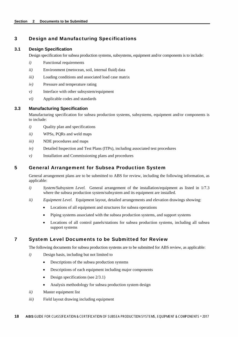
3 Design and Manufacturing Specifications
3.1 Design Specification Design specification for subsea production systems, subsystems, equipment and/or components is to include:
i) Functional requirements
ii) Environment (metocean, soil, internal fluid) data
iii) Loading conditions and associated load case matrix
iv) Pressure and temperature rating
v) Interface with other subsystem/equipment
vi) Applicable codes and standards
3.3 Manufacturing Specification Manufacturing specification for subsea production systems, subsystems, equipment and/or components is to include:
i) Quality plan and specifications
ii) WPSs, PQRs and weld maps
iii) NDE procedures and maps
iv) Detailed Inspection and Test Plans (ITPs), including associated test procedures
v) Installation and Commissioning plans and procedures
5 General Arrangement for Subsea Production System General arrangement plans are to be submitted to ABS for review, including the following information, as applicable:
i) System/Subsystem Level. General arrangement of the installation/equipment as listed in 1/7.3 where the subsea production system/subsystem and its equipment are installed.
ii) Equipment Level. Equipment layout, detailed arrangements and elevation drawings showing:
• Locations of all equipment and structures for subsea operations
• Piping systems associated with the subsea production systems, and support systems
• Locations of all control panels/stations for subsea production systems, including all subsea support systems
7 System Level Documents to be Submitted for Review The following documents for subsea production systems are to be submitted for ABS review, as applicable:
i) Design basis, including but not limited to
• Descriptions of the subsea production systems
• Descriptions of each equipment including major components
• Design specifications (see 2/3.1)
• Analysis methodology for subsea production system design
ii) Master equipment list
iii) Field layout drawing including equipment
18 ABS GUIDE FOR CLASSIFICATION & CERTIFICATION OF SUBSEA PRODUCTION SYSTEMS, EQUIPMENT & COMPONENTS . 2017

Section 2 Documents to be Submitted
iv) Assembly drawings, diagrams and schematics (including for equipment, piping and instrumentation diagrams/drawings (P&IDs), hydraulic, electrical and control schematics)
v) Cause and effect chart
vi) HAZID and/or HAZOP study reports for the entire subsea production systems and all associated subsystems
vii) FMEA/FMECA or similar analysis, and its validation program for integrated systems
viii) Safety principle and philosophy
ix) System Integrity Test (SIT) procedure and report
9 Subsystem/Equipment/Component Level Documents to be Submitted for Review
9.1 Design Documents 9.1.1 Design Documents for Subsystem/Equipment/Component
The following documents are to be submitted to ABS for review, as applicable. Flowline and riser documentation requirements are to follow the Pipeline Guide and Riser Guide, respectively. For documentation for Electrical and Control Systems, see 2/9.1.2.
i) Design basis, including
• Design specifications (see 2/3.1)
• P&IDs and schematic diagrams
• Design analysis methodology, procedures and load case matrices
• Manufacture and installation tolerances
• Specification of the internal fluid
• Corrosion/erosion allowances for piping
ii) Bill of material
iii) Material specifications, properties and traceability
iv) Drawings of arrangement, stack-up, scope of supply, assembly, interface, and marking, as appropriate
v) Analysis Reports. Any analysis required by applicable codes and standards as listed in this Guide as a minimum is to be included to verify the integrity of the equipment for all design conditions as listed in 3/1.7 as applicable
vi) Weights report including centers-of-mass for equipment
vii) FMEA/FMECA or similar analysis, and its validation program
viii) Corrosion control and protection details
ix) Manufacturer’s affidavit of compliance (see 4/3.1.2)
x) Site geotechnical/ geophysical reports
9.1.2 Design Documents for Electrical and Control System The following documents for subsea electrical and control system are to be submitted to ABS for review, as applicable
i) Functional Description Document (FDD) for control and instrumentation equipment
ii) Control system details
• Details on hierarchy of controls: primary, secondary, emergency, etc.
• Details and description of interconnections between control systems
ABS GUIDE FOR CLASSIFICATION & CERTIFICATION OF SUBSEA PRODUCTION SYSTEMS, EQUIPMENT & COMPONENTS . 2017 19

Section 2 Documents to be Submitted
• Primary power source and emergency power source details
• Volumetric capacity calculations for the accumulator systems, primary and secondary
• Hydraulic power unit (HPU) details/arrangements
- Pump system details and arrangements
- Prime mover details
- Reservoir capacity and arrangements
• Hydraulic and electrical schematics
• Pressure relief system
- Arrangements
- Size
- Materials
- Back pressure and capacity calculation
• Manufacturing/inspection/test specifications
iii) Design and details of subsea control system fail-safe principle, and FMEA/FMECA study
iv) Document on safety integrity levels (SIL) in accordance with IEC 61508 and alarm classification
v) Shutdown logic and/or shutdown (including ESD and PSD) cause and effect charts
vi) Drawings and schematics, including
• Arrangement drawing showing location and/or deployment of units controlled, instrumentation and control devices and set points for control system components
• Arrangements and details of topside control consoles/panels (e.g. MCC, MCS, HTP, etc.), including front views, installation arrangements together with schematic plans and logic description for all power, control and monitoring systems, including their functions
• Type and size of all electrical and/or fiber optic/signal cables and wiring associated with control systems (e.g., surface to surface, surface to subsea, and subsea to subsea), including voltage rating, service voltage, maximum acceptable voltage drop and currents, together with overload and short-circuit protection, conductors materials and dimension, insulation and external metallic protection specification, cable grounding as applicable, and the standards/codes the design is referenced to or is in compliance with
• Schematic plans and logic description of hydraulic and electrical control systems together with all interconnections, piping sizes and materials, including working pressures, relief-valve settings, and end connector/pull-in head/bend restrictor
• Description of all alarm and emergency tripping arrangements and functional sketches or description of all special valves, actuators, sensors and relays
vii) Design report, including:
• Calculations for control systems demonstrating the system’s ability to react adequately to anticipated occurrences, including transients, minimize well shut-down, disruption to the operations and production losses due to unexpected failures on any subsea controls system component or subsystem
20 ABS GUIDE FOR CLASSIFICATION & CERTIFICATION OF SUBSEA PRODUCTION SYSTEMS, EQUIPMENT & COMPONENTS . 2017

Section 2 Documents to be Submitted
• Details for external/internal corrosion protection (e.g., cathodic protection, and corrosion allowance) of subsea control components and equipment
• Design specifications for electrical communication system and protocol, and/or hydraulic analysis for hydraulic supply and confirming system response time, as applicable
• Design specifications for control valve/choke valve, chemical/methanol dosing requirements, and scale inhibitor system
• Design specifications for electrical jumper and connector, hydraulic/chemical jumper and connector, and umbilical/flying lead/jumper installation arrangement as applicable
• Design specifications for subsea electronic modules’ (SEM) hardware, software, and instrumentation
• Design specifications for surface controlled subsurface safety valve (SCSSSV)
viii) Hydrocarbon detection system plans and data, including detectors, piping, set points, type of detectors, and location of alarm panels
ix) Computer-based systems plans and data
x) Control system operating and maintenance manuals (including subsea control equipment maintenance and repair access/lift up arrangement and/or other intervention plan)
9.3 Manufacturing Documents 9.3.1 Materials, Welding and NDE
Materials used for pressurized members, load bearing (structural and/or mechanical) members, and threaded fasteners, are to be furnished with material manufacturer/mill’s documentation (e.g., material test reports (MTR), etc.) stating as a minimum, the following, as applicable
i) Certification by the material manufacturer/mill of compliance with the applicable recognized material specification or manufacturer’s written specification
ii) Material specification, grade
iii) Process of manufacture, including melting practices, reduction ratio
iv) Product heat number/batch number
v) Chemical analysis, with tolerance ranges and testing standard(s)
vi) Heat treatment records (showing heat treatment times at temperatures, heating and cooling rate, quenching media, transfer time, photographic evidence of components in furnace showing compliance to the furnace loading diagram, heat treating equipment)
vii) Re-heat treatment information
viii) Mechanical properties, including acceptance criteria:
• Tensile properties and testing standard(s)
• Charpy impact values and temperatures, including testing standard
• Hardness test readings (according to NACE MR0175/ISO 15156 standards), including testing standards
ix) Surface treatment information: evidence of surface hardening, coating, plating, thermal spraying, cladding, insulation, etc., to show compliance with the material specification
x) Dimension report
xi) WPSs, PQRs and weld maps
xii) NDE procedures and maps
xiii) NDE results including acceptance and rejection criteria
ABS GUIDE FOR CLASSIFICATION & CERTIFICATION OF SUBSEA PRODUCTION SYSTEMS, EQUIPMENT & COMPONENTS . 2017 21

Section 2 Documents to be Submitted
xiv) Corrective actions and disposition of major non-conformances during the material manufacturing or forming process
xv) In case repair welding is permitted, weld repair map and associated documentation is to be included
xvi) Material storage requirements
9.3.2 Fabrication Documents The following fabrication documents for subsea equipment during manufacturing phase are to be submitted to ABS for review, as applicable
i) Manufacturing and quality control documents
ii) Fabrication details and procedures (structure fabrication procedure, heat treatment, dimension control, etc.)
iii) Manufacturer databook
iv) Detailed Inspection and Test Plans (ITPs) for manufacturing phase including associated test procedures for system, subsystem, equipment or component, as outlined in Section 4, Table 1, as applicable
9.3.3 Testing Documents The following documents for testing of subsea equipment during manufacturing phase are to be submitted to ABS for review, as applicable
i) Testing procedure including testing specification, acceptance criteria, testing tools and equipment used, along with calibration data
ii) Testing reports for validation testing, FAT, EFAT
9.5 Installation/Commissioning Documents The following documents during the installation/commissioning phase are to be submitted to ABS for review, as applicable
i) Detailed Inspection and Test Plans (ITPs) for installation/commissioning phase
ii) SIT procedures and reports
iii) Installation manual including deployment, abandonment and retrieval
iv) Lifting arrangement
v) Installation analysis report per applicable codes and standards if it is not reviewed at the design phase
vi) Post-installation survey report
vii) Contingency procedures
9.7 In-service Documents The following documents are to be submitted to ABS
i) In Service Inspection Plan (ISIP)
ii) Repair and replacement plan, as identified by the inspection
iii) Maintenance documentation
22 ABS GUIDE FOR CLASSIFICATION & CERTIFICATION OF SUBSEA PRODUCTION SYSTEMS, EQUIPMENT & COMPONENTS . 2017

Section 2 Documents to be Submitted
9.9 Life Extension Documents The following documents for life extension of subsea structures during operation life management phase are to be submitted to ABS for review, as applicable
i) Inspection and test record
ii) An application document to propose life extension of the subsea structure including
• Proposed continuing operation life
• Proposed continuing operation conditions including environmental conditions
• Inspected structure condition
• Environmental/geotechnical condition changes record
• Corrosion history, predicted corrosion rate and predicted end of life condition
• Proposed repair and replacement
• Future inspection/monitoring plan, inspection interval and acceptance criteria
• Proposed testing plan including pressure limits and testing interval
iii) Analysis reports for life extension of the subsea structure including
• Strength assessment per inspected condition
• Fatigue damage accumulated based on previous operation history
• Strength analysis for the structure per structure and system condition at the end of proposed life extension, under proposed the worst environmental condition, considering proposed repair and replacement
• Remaining fatigue life per inspected condition and predicted corrosion under proposed continuing operating conditions considering proposed repair and replacement
9.11 Decommissioning Phase (for I3P service) The following documents during decommissioning phase are to be submitted to ABS for review, as applicable:
i) Decommissioning basis including applicable codes and standards
ii) Documents defining the scope of work for decommissioning
iii) Decommissioning manual and procedure
iv) Lifting arrangement
v) Retrieval analysis report similar to the installation report in 2/9.5v)
ABS GUIDE FOR CLASSIFICATION & CERTIFICATION OF SUBSEA PRODUCTION SYSTEMS, EQUIPMENT & COMPONENTS . 2017 23

S e c t i o n 3 : R e q u i r e m e n t s f o r C l a s s i f i c a t i o n / C e r t i f i c a t i o n
S E C T I O N 3 Requirements for Classification/Certification
This Section provides the general design considerations and requirements for Classification/Certification of subsea production systems, subsystems, equipment and/or components. The maintenance of classification during the service lives of subsea production systems/subsystems is dependent upon meeting the requirements contained herein for periodical surveys as specified in Section 6 in this Guide.
The general design considerations and general design requirements are outlined in Subsections 3/1 and 3/3, respectively. Detailed requirements for each subsystem/equipment are specified in 3/5.1 to 3/5.27, while 3/5.29 summarizes the governing API standards for each subsystem/equipment listed in 3/5.1 to 3/5.27.
1 General Design Considerations
1.1 Recognized Standards The design of subsea production systems, subsystems, equipment and/or components is to be in accordance with the requirements of this Guide and the latest edition of the specified codes and standards, as referenced herein and in Appendix 2, based on the project contract date or request for class signed date.
i) Designs complying with other international or national standards not listed in Appendix 2 will be subject to special consideration in accordance with 1/7.5.
ii) ABS recommends that the designer/manufacturer contact the ABS Technical office early in the design phase for acceptance of alternate design codes and standards.
iii) When alternate design codes and standards are proposed, justifications can be achieved through equivalency, gap analysis or appropriate risk analysis to demonstrate that the proposed alternate design code and standard will provide an equivalent level of safety to the recognized standards as listed in this Guide, and are required to be performed in accordance with 1/7.7.
1.3 Alternative Basis of Design Designs based on manufacturers’ standards may also be accepted. In such cases, complete details of the manufacturer’s standard and engineering justification are to be submitted for review.
i) The manufacturer will be required to demonstrate by way of testing or analysis that the design criteria employed results in a level of safety consistent with that of a recognized standard or code of practice.
ii) Where strain gauge testing, fracture analysis, proof testing or similar procedures form a part of the manufacturer’s design criteria, specifics of the procedure and results are to be submitted for ABS review.
iii) Historical performance data for subsea production systems, subsystems, equipment and/or components is to be submitted for justification of designs based on manufacturers’ standards.
iv) ABS will consider the application of risk evaluations for alternative or novel features for the basis of design in accordance with 1/7.7, as applicable.
24 ABS GUIDE FOR CLASSIFICATION & CERTIFICATION OF SUBSEA PRODUCTION SYSTEMS, EQUIPMENT & COMPONENTS . 2017

Section 3 Requirements for Classification/Certification
1.5 Risk Assessments for Subsea Production Systems All hazards that may affect the subsea production system or any of its subsystems, equipment, and/or components are to be properly identified and risks managed to a tolerable level with implementation of effective risk control options. A systematic process is to be applied to identify situations where a combination or sequence of events could lead to undesirable consequences (property damage, personnel safety and environmental damage), with consideration given to all reasonably foreseeable causes.
The identified risk control options (prevention and mitigation measures) deemed necessary to be implemented are to be considered part of the design basis of the subsea production system.
Appendix 4 in the ABS Guide for Risk Evaluations for the Classification of Marine-Related Facilities contains a description of the most common hazard identification techniques. Also, Appendix 2 in the same Guide provides an overview of how to assemble an appropriate risk assessment team.
1.5.1 Hazard Identification (HAZID) A HAZID study is to be conducted for the overall subsea production system. ABS’ participation in this HAZID study is required.
1.5.2 FMEA/FMECA The purpose of a FMEA is to verify that the individual subsea production systems, subsystems and equipment comply with the following design philosophy:
i) No single failure will lead to a hazardous situation to people, environment or equipment, and
ii) That there are at least two means of protection in place to prevent the hazardous event.
A functional FMEA/FMECA is to be conducted for individual systems, subsystems and their associated control systems and submitted for review. Based on the results of functional FMEA/FMECA, a component level FMEA/FMECA may be deemed necessary to be perform for the critical components as identified during the functional FMEA/FMECA.
If component level FMEA/FMECA is required, the results of the component level FMEA/FMECA is to correlate to the functional FMEA/FMECA to provide an overall understanding of the local effects of the equipment failure mode and ‘global’ effects of the failure of the control/safety function and other equipment/ interfaces in the system.
Functional FMEA/FMECA and component level FMECA can be conducted in accordance with API RP17N, the ABS Guidance Notes on Qualifying New Technologies and the ABS Guidance Notes on Failure Mode and Effects Analysis (FMEA) for Classification.
A FMEA/FMECA Validation Program and related test procedures are to be developed and submitted for review. The purpose of the FMEA/FMECA Validation Program is to verify critical and selected results (that are not already covered by FAT and SIT procedures) from the FMEA.
The specific goals of the tests are to validate the:
• Effectiveness of system to identify failures
• Effect of identified failures on system/equipment
• Response of safety controls
• Other measures to protect against failure
Validation tests are to be carried out during factory acceptance testing and/or as part of the onboard commissioning of the integrated systems in accordance with the approved program and verified by the attending Surveyor.
When final testing requires assembly and installation on-board the facility, it may not be possible to perform all required testing at vendor’s plant. In this case, FMEA/FMECA Validation testing is be carried out as part of the system integration testing (SIT) during commissioning. Any modifications made to the Validation test plan are to be submitted for review.
7/1.11 of the ABS Guidance Notes on Failure Mode and Effects Analysis (FMEA) for Classification provides detailed steps for the FMEA/FMECA and FMEA Validation Program.
ABS GUIDE FOR CLASSIFICATION & CERTIFICATION OF SUBSEA PRODUCTION SYSTEMS, EQUIPMENT & COMPONENTS . 2017 25
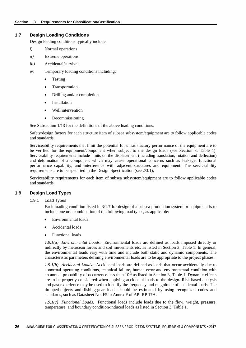
Section 3 Requirements for Classification/Certification
1.7 Design Loading Conditions Design loading conditions typically include:
i) Normal operations
ii) Extreme operations
iii) Accidental/survival
iv) Temporary loading conditions including:
• Testing
• Transportation
• Drilling and/or completion
• Installation
• Well intervention
• Decommissioning
See Subsection 1/13 for the definitions of the above loading conditions.
Safety/design factors for each structure item of subsea subsystem/equipment are to follow applicable codes and standards.
Serviceability requirements that limit the potential for unsatisfactory performance of the equipment are to be verified for the equipment/component when subject to the design loads (see Section 3, Table 1). Serviceability requirements include limits on the displacement (including translation, rotation and deflection) and deformation of a component which may cause operational concerns such as leakage, functional performance capability, and interference with adjacent structures and equipment. The serviceability requirements are to be specified in the Design Specification (see 2/3.1).
Serviceability requirements for each item of subsea subsystem/equipment are to follow applicable codes and standards.
1.9 Design Load Types 1.9.1 Load Types
Each loading condition listed in 3/1.7 for design of a subsea production system or equipment is to include one or a combination of the following load types, as applicable:
• Environmental loads
• Accidental loads
• Functional loads
1.9.1(a) Environmental Loads. Environmental loads are defined as loads imposed directly or indirectly by metocean forces and soil movements etc. as listed in Section 3, Table 1. In general, the environmental loads vary with time and include both static and dynamic components. The characteristic parameters defining environmental loads are to be appropriate to the project phases.
1.9.1(b) Accidental Loads. Accidental loads are defined as loads that occur accidentally due to abnormal operating conditions, technical failure, human error and environmental condition with an annual probability of occurrence less than 10-2 as listed in Section 3, Table 1. Dynamic effects are to be properly considered when applying accidental loads to the design. Risk-based analysis and past experience may be used to identify the frequency and magnitude of accidental loads. The dropped-objects and fishing-gear loads should be estimated by using recognized codes and standards, such as Datasheet No. F5 in Annex F of API RP 17A.
1.9.1(c) Functional Loads. Functional loads include loads due to the flow, weight, pressure, temperature, and boundary condition-induced loads as listed in Section 3, Table 1.
26 ABS GUIDE FOR CLASSIFICATION & CERTIFICATION OF SUBSEA PRODUCTION SYSTEMS, EQUIPMENT & COMPONENTS . 2017
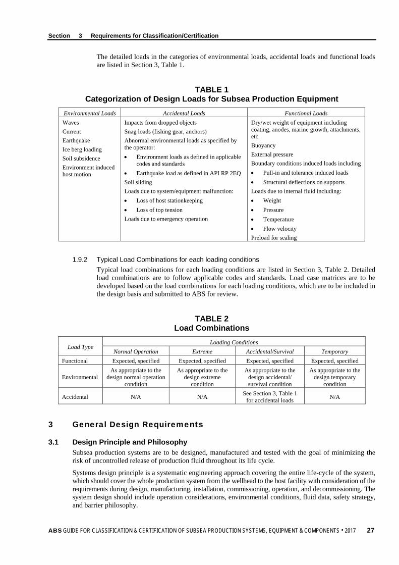
Section 3 Requirements for Classification/Certification
The detailed loads in the categories of environmental loads, accidental loads and functional loads are listed in Section 3, Table 1.
TABLE 1 Categorization of Design Loads for Subsea Production Equipment
Environmental Loads Accidental Loads Functional Loads Waves Current Earthquake Ice berg loading Soil subsidence Environment induced host motion
Impacts from dropped objects Snag loads (fishing gear, anchors) Abnormal environmental loads as specified by the operator: • Environment loads as defined in applicable
codes and standards • Earthquake load as defined in API RP 2EQ Soil sliding Loads due to system/equipment malfunction: • Loss of host stationkeeping • Loss of top tension Loads due to emergency operation
Dry/wet weight of equipment including coating, anodes, marine growth, attachments, etc. Buoyancy External pressure Boundary conditions induced loads including • Pull-in and tolerance induced loads • Structural deflections on supports Loads due to internal fluid including: • Weight • Pressure • Temperature • Flow velocity Preload for sealing
1.9.2 Typical Load Combinations for each loading conditions Typical load combinations for each loading conditions are listed in Section 3, Table 2. Detailed load combinations are to follow applicable codes and standards. Load case matrices are to be developed based on the load combinations for each loading conditions, which are to be included in the design basis and submitted to ABS for review.
TABLE 2 Load Combinations
Load Type Loading Conditions
Normal Operation Extreme Accidental/Survival Temporary Functional Expected, specified Expected, specified Expected, specified Expected, specified
Environmental As appropriate to the
design normal operation condition
As appropriate to the design extreme
condition
As appropriate to the design accidental/ survival condition
As appropriate to the design temporary
condition
Accidental N/A N/A See Section 3, Table 1 for accidental loads N/A
3 General Design Requirements
3.1 Design Principle and Philosophy Subsea production systems are to be designed, manufactured and tested with the goal of minimizing the risk of uncontrolled release of production fluid throughout its life cycle.
Systems design principle is a systematic engineering approach covering the entire life-cycle of the system, which should cover the whole production system from the wellhead to the host facility with consideration of the requirements during design, manufacturing, installation, commissioning, operation, and decommissioning. The system design should include operation considerations, environmental conditions, fluid data, safety strategy, and barrier philosophy.
ABS GUIDE FOR CLASSIFICATION & CERTIFICATION OF SUBSEA PRODUCTION SYSTEMS, EQUIPMENT & COMPONENTS . 2017 27

Section 3 Requirements for Classification/Certification
A safety strategy should be established to identify and mitigate risks, develop the level of safety of the system and performance requirements for safety systems and barriers in accordance with API RP 17A and API RP 17V.
A comprehensive barrier philosophy is to be developed. The barrier philosophy should provide clear and concise guidance on barrier requirements to prevent unintentional release of produced/injected fluids. The barrier philosophy is to cover all of the pressure-containing equipment/components in the system in accordance with API RP 17A, as applicable.
3.3 System Requirements A systematic approach is to be implemented for the life cycle of the subsea equipment including design, manufacturing, installation/commissioning, operation and decommissioning phases. Design plans and data are to account for all the above phases. The system design is to follow applicable API 17 series documents and this Guide.
3.5 Field Layout Arrangements and installation of subsea production systems, subsystems, equipment and/or components are to be in accordance with the overall process safety principles given in the ABS Facilities Rules for surface equipment and API RP 17A for subsea equipment.
3.7 Materials, Welding and Nondestructive Examination The materials for each equipment and/or component are to be selected with consideration of their fitness for the intended service and in accordance with the applicable codes and standards as referenced in this Guide, in addition to the material requirements of Section 5.
The experience of the manufacturers, designers and related performance records will be specially considered with technical justifications in accordance with 2/9.3.
General requirements for welding and nondestructive examination (NDE) are to be in accordance with Section 5.
3.9 Corrosion/Erosion Allowance Where subsea production systems, subsystems, equipment, and/or components are subjected to a corrosive, erosive or abrasive environment, the design is to include allowances for such extra material as applicable in accordance with the following requirements
i) As specified by the applicable design codes and standards.
ii) The amount of additional material needed is to be determined based on the predicted rate of corrosion and/or erosion and the design service life of the component.
iii) Alternative allowances will be considered when supplemented with technical justifications for the life-cycle of the equipment, such as:
a) Previous documented service experience
b) Active corrosion protection and maintenance, such as anodes
c) Passive corrosion protection and maintenance, such as special coatings
iv) In the absence of conformity to 3/3.9i) through 3/3.9iii), a minimum corrosion allowance of 1.6 mm (0.0625 in.) is to be utilized.
3.11 Overpressurization Protection Subsea production systems, subsystems, equipment, and/or components that may have the potential of exposure to pressure greater than for which they are designed are to be protected by suitable pressure protection devices:
28 ABS GUIDE FOR CLASSIFICATION & CERTIFICATION OF SUBSEA PRODUCTION SYSTEMS, EQUIPMENT & COMPONENTS . 2017

Section 3 Requirements for Classification/Certification
i) The subsea production systems, subsystems, equipment and/or components that may have the possibility of overpressure are to be protected by suitable means, acceptable to ABS, such as HIPPS or the equivalent. See also the requirements in 3/3.1 on design principle and philosophy. The equipment will be reviewed for the specified design parameters, as specified in the applicable “Design Basis” in Section 2.
ii) It is to be the responsibility of the systems and equipment designers to specify and consider the most severe combination of pressure sources, such as formation pressure, pumps, flow restriction, static heads, hammer effects, thermally-induced pressures, in the design and selection of suitable overpressure protection devices.
3.13 Loads All applicable loads that can affect the subsea production system during all phases of the life cycle, from manufacturing through decommissioning, are to be defined and taken into account in the design in accordance with 3/1.7 and 3/1.9.
3.15 Strength All the loading conditions in the life cycle of the equipment are to be considered for equipment strength analysis. Safety/design factor based on the minimum material yield strength is to be used in the design calculations in accordance with recognized codes and standards for specific equipment. Metal material strength de-rating is to be considered per applicable codes and standards.
3.17 Fatigue/Fracture Fatigue screening is to be carried out with consideration of cyclic loads for all design phases including design fabrication, design transportation, design installation, and design operation. If equipment/components are identified as fatigue sensitive, fatigue analysis is to be carried out based on S-N curves method or fracture mechanics per applicable codes and standards.
3.19 High-Pressure High-Temperature (HPHT) Applications For high-pressure high-temperature (HPHT) applications [i.e., operating scope greater than 103.43 MPa (15,000 psi) and/or greater than 177°C (350°F)], the system level considerations are to be in accordance with API TR 1PER15K-1 while requirements on materials, seals and bolting/fasteners, design verification and design validation for subsea equipment other than riser and pipeline are to follow API 17TR8.
5 Subsystem/Equipment Requirements
5.1 Subsea Connectors The design, fabrication, installation, inspection and testing of connectors for subsea wellhead and tree is to conform to API SPEC 17D. Detailed guidance on the verification and validation of subsea wellhead and tree connectors is contained in API 17TR7.
The design, fabrication, installation, inspection and testing of subsea flowline connector is to conform to API RP 17R.
5.3 Wellhead, Tree and Tubing Hanger 5.3.1 Subsea Wellhead, Tree and Tubing Hanger
The design, fabrication, installation, inspection and testing of subsea wellhead, tree, and tubing hanger are to follow API SPEC 17D.
The wellhead system provides structural foundation for a subsea completion. The subsea wellhead system supports the interior casing strings as well as the BOP stack during drilling, and the subsea tree and the tubing hanger after completion. The subsea wellhead system is installed at or near the mudline. Subsea wellheads may contain the following components, as applicable
ABS GUIDE FOR CLASSIFICATION & CERTIFICATION OF SUBSEA PRODUCTION SYSTEMS, EQUIPMENT & COMPONENTS . 2017 29

Section 3 Requirements for Classification/Certification
• Temporary guidebase
• Permanent guidebase
• Conductor housing
• Wellhead housing
• Casing hangers and annulus seal assemblies
The subsea tree is an assembly of valves, spools, and fittings used for a subsea well. The components of a subsea tree may include the following components, as applicable
• Wellhead connector
• Studs, nuts and bolting
• Ring gaskets
• Tree/tubing head spool connector and tubing head
• Tree stab/seal stubs for vertical tree
• Valves, valve blocks and actuators
• TFL wye spool and diverter
• Re-entry interface
• Completion guidebase
• Tree-guide frame
• Tree piping
• Flowline connector
• Tree-mounted control interfaces
• Subsea chokes and actuators
The tubing hanger is a tubing-suspension device. The tubing hanger may be landed in a wellhead, tubing head or horizontal tree.
In the ultimate strength and fatigue analysis for the wellhead and tree, temporary loading conditions such as drilling and/or workover are significant. In the drilling or workover loading conditions, global analysis is typically performed before the local detail analysis. In the global drilling system analysis, integrated system modeling including soil, riser and host motion are to be simulated for applicable operation scenarios such as normal drilling, connected non-drilling, drift-off/drive-off, etc. See the ABS Guidance Notes on Drilling Riser Analysis for details of the global system modeling and analysis procedures for applicable operation scenarios. The same integrated system modeling is also to be applied for global workover system analysis. For the integrated workover system analysis, API RP17G is to be followed.
5.3.2 Surface Wellhead, Tree and Tubing Hanger The design, fabrication, installation, inspection and testing of surface wellhead, tree (dry tree) and tubing hanger is to follow API SPEC 6A.
5.5 Flowline, Jumper and Riser 5.5.1 Flowline
A subsea flowline transports unprocessed reservoir fluids originally from a well to process equipment. Depending on the materials and construction method used, the design, fabrication, installation, inspection and testing of a flowline is to be in accordance with the following API standards:
30 ABS GUIDE FOR CLASSIFICATION & CERTIFICATION OF SUBSEA PRODUCTION SYSTEMS, EQUIPMENT & COMPONENTS . 2017

Section 3 Requirements for Classification/Certification
• RP 1111 for metallic flowline
• RP 17B for flowline
• SPEC 17J for flowline
• SPEC 17K for flowline
Design for route determination, global lateral buckling and strength assessment of a damaged flowline is to be in accordance with the ABS Pipeline Guide. See the ABS Guidance Notes on Subsea Pipeline Route Determination for guidance on flowline route determination.
5.5.2 Jumper A subsea jumper transports fluid and provides an interface between two separate components installed. A jumper will serve as a connection between two of the following items:
• Subsea tree
• Manifold
• Flowline segment
• Injection line segment
• Riser
• In-line structure
The design, fabrication, installation, inspection and testing of a subsea jumper is to follow API RP 17R.
5.5.3 Riser A riser is a conduit of fluid between the seafloor and a surface facility. Risers may be one of the following types:
• Production
• Drilling
• Workover/completion
• Gas and water injection
• Gas lift
• Export
Requirements on production risers are in the following paragraphs. Injection risers and gas lift risers are covered in 3/5.11. Other types of risers are outside of the scope of this Guide.
Depending on the materials and construction method used, the design, fabrication, installation, inspection and testing of dynamic production risers are to be in accordance with the following API standards:
• STD 2RD for metallic risers
• RP 17B for flexible risers
• SPEC 17J for unbonded flexible risers
• SPEC 17K for bonded flexible risers
The design of hybrid riser systems is to be in accordance with the ABS Riser Guide. See the ABS Guidance Notes on Subsea Hybrid Riser Systems for detailed design guidance on hybrid riser systems.
ABS GUIDE FOR CLASSIFICATION & CERTIFICATION OF SUBSEA PRODUCTION SYSTEMS, EQUIPMENT & COMPONENTS . 2017 31

Section 3 Requirements for Classification/Certification
5.7 HIPPS The HIPPS is a mechanical and electrical-hydraulic safety instrumented system that protects downstream equipment from full shut-in tubing head pressure (SITHP). It allows the use of flowlines which are not rated for the SITHP or tie-in of new “high pressure” production systems into “low pressure” processing facilities. The HIPPS is to be designed so as to isolate the lower-pressure-rated equipment/components of the system from the SITHP in all conditions. For the control system for HIPPS, see 3/5.17.
The design, fabrication, installation, inspection and testing of HIPPS is to follow API STD 17O and this Guide.
5.9 Manifold/PLEM/PLET and Template A manifold consists of headers, branched piping and valves that gather and distribute produced and/or injected fluids. The manifold can be used for well testing and well servicing as well. The cluster manifold is a manifold commingling flow from a number of subsea wells into one or more headers.
A PLEM is similar to a cluster manifold, however, a PLEM is generally integral to the flowline and has more than one subsea flowline end connection. The PLET is similar to a PLEM, however, typically has only one subsea flowline end connection.
A template is a seabed structure that generally provides guide and support for drilling. It may include production/injection piping. A template is typically used to group several subsea wells at a single seabed location. The template can be of an integrated or modular design.
A manifold can be integral with a template. The design, fabrication, installation, inspection and testing of manifold/PLEM/PLET and template is to follow API RP 17P. For foundations, see 3/5.25.
5.11 Injection and Service Systems Injection lines transport fluids (e.g., gas or water) to be injected directly into a reservoir. Service lines include:
• Chemical injection lines
• Gas lift lines
• Annulus monitoring lines
• Kill lines
• Lines dedicated to through-flowline operations
• Bundle heating lines, etc.
The design, fabrication, installation, inspection and testing of injection and service systems is to follow API RP 17A.
Some service lines are normally integrated into umbilicals, such as chemical injection lines, therefore the applicable requirements of API SPEC 17E are also to be satisfied. Some service lines go through flowlines or are bundled with the flowline (such as bundle heating lines), therefore applicable requirements in referenced riser and flowline standards are to be followed as well.
5.13 Umbilical/Flying Lead The subsea umbilical contains a group of functional components (e.g., electric cables, optical fiber cables, hoses, and tubes) that generally provide hydraulics, fluid injection, power and/or communication services. The functional components may be laid up or bundled together or in combination with each other. The flying lead can be considered as a short length umbilical. The flying lead is a single or multiple composite grouping of hydraulic, chemical, electrical power, electrical signal, and/or optical signal connecting various items of subsea equipment such as from wellhead to manifold.
The design, fabrication, installation, inspection and testing of a subsea umbilical, its associated ancillary equipment and hydraulic flying lead is to follow API SPEC 17E. The design, fabrication, installation, inspection and testing of a subsea electric flying lead is to follow API STD 17F.
32 ABS GUIDE FOR CLASSIFICATION & CERTIFICATION OF SUBSEA PRODUCTION SYSTEMS, EQUIPMENT & COMPONENTS . 2017
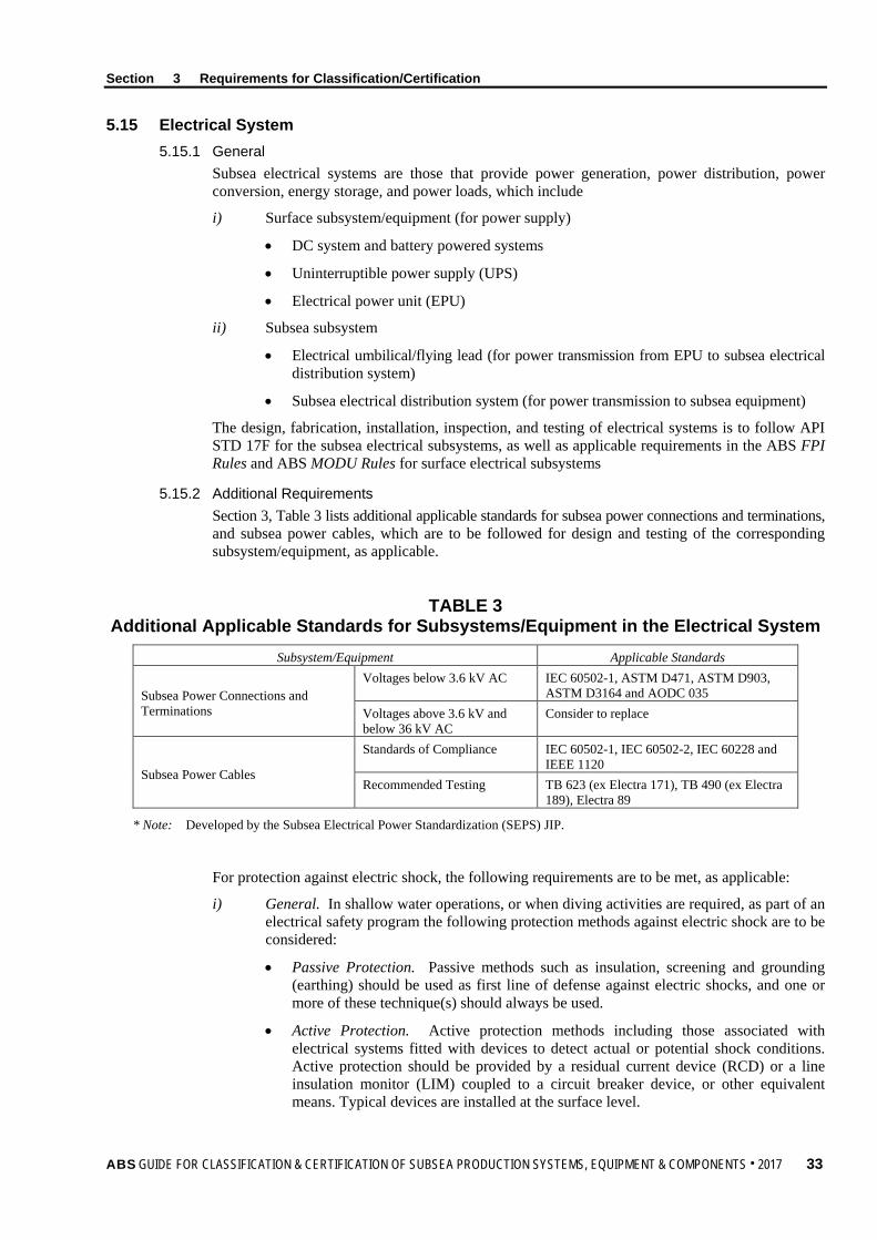
Section 3 Requirements for Classification/Certification
5.15 Electrical System 5.15.1 General
Subsea electrical systems are those that provide power generation, power distribution, power conversion, energy storage, and power loads, which include
i) Surface subsystem/equipment (for power supply)
• DC system and battery powered systems
• Uninterruptible power supply (UPS)
• Electrical power unit (EPU)
ii) Subsea subsystem
• Electrical umbilical/flying lead (for power transmission from EPU to subsea electrical distribution system)
• Subsea electrical distribution system (for power transmission to subsea equipment)
The design, fabrication, installation, inspection, and testing of electrical systems is to follow API STD 17F for the subsea electrical subsystems, as well as applicable requirements in the ABS FPI Rules and ABS MODU Rules for surface electrical subsystems
5.15.2 Additional Requirements Section 3, Table 3 lists additional applicable standards for subsea power connections and terminations, and subsea power cables, which are to be followed for design and testing of the corresponding subsystem/equipment, as applicable.
TABLE 3 Additional Applicable Standards for Subsystems/Equipment in the Electrical System
Subsystem/Equipment Applicable Standards
Subsea Power Connections and Terminations
Voltages below 3.6 kV AC IEC 60502-1, ASTM D471, ASTM D903, ASTM D3164 and AODC 035
Voltages above 3.6 kV and below 36 kV AC
Consider to replace
Subsea Power Cables
Standards of Compliance IEC 60502-1, IEC 60502-2, IEC 60228 and IEEE 1120
Recommended Testing TB 623 (ex Electra 171), TB 490 (ex Electra 189), Electra 89
* Note: Developed by the Subsea Electrical Power Standardization (SEPS) JIP.
For protection against electric shock, the following requirements are to be met, as applicable:
i) General. In shallow water operations, or when diving activities are required, as part of an electrical safety program the following protection methods against electric shock are to be considered:
• Passive Protection. Passive methods such as insulation, screening and grounding (earthing) should be used as first line of defense against electric shocks, and one or more of these technique(s) should always be used.
• Active Protection. Active protection methods including those associated with electrical systems fitted with devices to detect actual or potential shock conditions. Active protection should be provided by a residual current device (RCD) or a line insulation monitor (LIM) coupled to a circuit breaker device, or other equivalent means. Typical devices are installed at the surface level.
ABS GUIDE FOR CLASSIFICATION & CERTIFICATION OF SUBSEA PRODUCTION SYSTEMS, EQUIPMENT & COMPONENTS . 2017 33

Section 3 Requirements for Classification/Certification
5.17 Control and Monitoring System 5.17.1 General
Control and monitoring systems of a subsea production system are those that provided controls and monitoring for a subsea production system, which typically includes safety subsystems, communication subsystems and shutdown subsystems. For the subsystem/equipment of the subsea control and monitoring system, see Section 4, Table 1.
The design, fabrication, installation, inspection and testing of control system is to follow
• API STD 17F for subsea control and monitoring subsystem
• Applicable requirements in the ABS FPI Rules and Chapter 3, Section 7 of the ABS Facilities Rules for surface control and monitoring subsystem
5.17.2 Additional Requirements Section 3, Table 4 lists additional applicable standards for safety subsystem, communication subsystem, shutdown subsystem, subsea umbilical termination (SUT) and computer-based systems, which are to be followed for design, fabrication, installation, inspection and testing of the corresponding subsystem/equipment.
TABLE 4 Additional Applicable Standards for Subsystems/Equipment in the Control and
Monitoring Subsystem Subsystem/Equipment Applicable Standards
Safety Systems and Equipment Surface Safety subsystems API RP 14C Subsea Safety Subsystem API RP 17V
Communication System and Equipment
Communication System API RP 17A Subsea Electrical and Fiber Optic Cables
IEC 60793, IEC 60794, IEC 60228, and IEC 60502
Shutdown System and Equipment API RP 17A, API STD 17O and API RP 17V Subsea Umbilical Termination (SUT) API 17TR10
Computer-Based Systems 4-9-3/5 (except 4-9-3/5.1.7 and 4-9-3/5.1.8) of the ABS Steel Vessel Rules
5.19 Capping Stack There are generally two categories of subsea capping stacks: Category 1 (Cap) and Category 2 (Cap and Flow). The capping stack is a subsea mechanical barrier that has the capability to shut in uncontrolled flow from a wellbore to the environment (Category 1) or, to divert flow from the wellbore to a containment system (Category 2.)
The design, fabrication, installation, inspection and testing of a subsea capping stack is to follow API RP 17W.
5.21 Flow Meters In subsea applications, multiphase flow meters are normally used in well testing, allocation measurement, fiscal measurement, well management, and/or in flow assurance applications. The design, fabrication, commissioning, inspection and testing of a subsea multiphase flow meter is to follow API RP 17S.
5.23 ROV/ROT Interfaces The design, fabrication, installation, inspection and testing of a ROV/ROT interface on subsea production equipment is to follow API RP 17H.
34 ABS GUIDE FOR CLASSIFICATION & CERTIFICATION OF SUBSEA PRODUCTION SYSTEMS, EQUIPMENT & COMPONENTS . 2017

Section 3 Requirements for Classification/Certification
5.25 Foundations The design of foundations for subsea equipment is to take into account all loads deemed necessary during the service life of the equipment including installation, operation and retrieval.
There are two types of foundations:
• Shallow foundation, such as mud mats, skirt foundation
• Pile foundation, such as driven pile, suction pile.
Foundation design is to be performed based on soil parameters obtained from site-specific investigations. The interaction between the soil and the foundation structure are to be taken into account in the foundation design. Site surveys, geotechnical investigations, and foundation designs are to be in accordance with API RP 2GEO. The structural buckling and ultimate strength of a foundation are to in conformance with the ABS Guide for Buckling and Ultimate Strength Assessment for Offshore Structures.
5.27 Subsea Protection Structures 5.27.1 General
Protection structures are used to protect equipment against damage from dropped objects, fishing gear, dragged anchors, ice and other incidental loads.
The design of the protection structure is to follow API RP 17P. The consideration of the loads from trawling and dropped objects is to follow API RP 17A or from a project-specific risk analysis in accordance with 3/1.5. The damage of the protection structure is not to affect the structure integrity of the equipment.
5.27.2 Overtrawlable Design For the sites subject to fishing activities or required by government, overtrawlable design is recommended for subsea structures and/or the protection structures.
The overtrawlable design is to follow API RP 17A and the analysis report of that design is to include the following calculations and data, as applicable
i) Evaluation of possibility of hooking to be avoided
ii) Historical trawling data (tracking data) of the field
iii) Trawl equipment specifications
iv) Trawling frequency
v) The maximum Trawling loads
vi) Trawl gear maximum impact load
vii) Trawl gear maximum pull-over load
viii) Structure deformation induced by impact and pull-over load
5.29 Summary of Governing API Standards for Each Subsystem/Equipment Section 3, Table 5 summarizes the governing API standards for each subsystem/equipment listed in 3/5.1 through 3/5.27.
ABS GUIDE FOR CLASSIFICATION & CERTIFICATION OF SUBSEA PRODUCTION SYSTEMS, EQUIPMENT & COMPONENTS . 2017 35

Section 3 Requirements for Classification/Certification
TABLE 5 Governing API Standards for Each Subsystem/Equipment
Subsystem/Equipment Governing API Standards Subsea Production System RP 17A Subsea Connectors SPEC 17D, 17TR7, RP 17R Subsea Wellhead, Tree and Tubing Hanger SPEC 17D Surface Wellhead, Tree and Tubing Hanger SPEC 6A Flowline, Jumper and Riser RP 1111, RP 17B, SPEC 17J, SPEC 17K, RP 17R, STD 2RD HIPPS STD 17O Manifold/PLEM/PLET and Template RP 17P Injection and Service Systems RP 17A, SPEC 17E, STD 2RD, RP 1111 Umbilical/Flying Lead SPEC 17E, STD 17F Electrical System STD 17F Control System STD 17F, RP 17V Capping Stack RP 17W Multiphase Flow Meter RP 17S ROV/ROT Interfaces RP 17H Foundation RP 2GEO Subsea Protection Structure RP 17P, RP 17A
5.31 Installation In addition to the requirements of the applicable standards for each subsystem/equipment as listed in Section 3, Table 5, the requirements on installation of subsea production equipment in API RP 17A are also applicable. Lifting equipment is to satisfy the requirements in applicable codes and standards, such as IMCA standards, ABS Guide for Certification of Lifting Appliances or ABS Rules for Building and Classing Offshore Support Vessels.
An installation analysis is to be carried out to verify that the structure integrity of the equipment during installation is acceptable. The analysis report is to be submitted to ABS for review as indicated in 2/9.5. Installation survey for classification/certification normally consists pre-installation verification and post-installation verification while the scope of installation survey for I3P service can be customized based on the client request.
36 ABS GUIDE FOR CLASSIFICATION & CERTIFICATION OF SUBSEA PRODUCTION SYSTEMS, EQUIPMENT & COMPONENTS . 2017

S e c t i o n 4 : C l a s s i f i c a t i o n / C e r t i f i c a t i o n P r o c e s s
S E C T I O N 4 Classification/Certification Process
1 General This Section provides detailed procedures for ABS Classification/Certification of typical subsea production systems, subsystems, equipment, and/or components that require design review and survey.
i) Section 4, Figure 1 shows the typical process of ABS Certification of subsea production systems, subsystems, equipment and components and the way forward to Classification of subsea production systems.
ii) Section 4, Table 1 is provided as a general reference listing, and is not to be considered as a list of complete subsea production systems, subsystems, equipment and/or components.
iii) For subsea production systems, subsystems, equipment and/or components not listed, the designer/ manufacturer is to contact the appropriate ABS Technical office for guidance on the approval process.
iv) ABS is prepared to consider alternative design methodology and industry practice for subsea production systems, subsystems, equipment, and/or components designs, on a case-by-case basis, with justification through novel features as indicated in 1/7.7.
Note: Process of Certification and Classification of subsea production systems are the same from design phase to installation/commissioning phase. The continuance of the Classification of subsea production systems during their service lives is dependent on meeting the requirements contained in this Guide for periodical surveys.
3 Certification and Classification Process ABS approval of subsea production systems, equipment, and/or components is to be in accordance with the applicable codes and standards regarding design, fabrication, and testing, and is also to comply with the additional requirements of this Guide.
i) Subsea production systems, subsystems, equipment, and/or components, including subsea support systems, are to be approved according to the following general procedures.
a) Documents are to be submitted in accordance with Section 4, Table 1 and Section 2.
b) ABS design review for issuance of the following documents (see 4/3.5)
1) ABS approval letter/PDA
2) Independent Review Certificate (IRC) as applicable. See Section 4, Table 1 and Appendix 4
c) ABS survey at vendor’s plant (see 4/3.3.1), and during installation and commissioning (see 4/3.3.2), as applicable, for issuance of the following documents See 4/3.5
1) Survey Report (SR) (see Section 4, Table 1 and Appendix 6)
2) Certificate of Compliance (CoC) as applicable. See Section 4, Table 1 and Appendix 7
ii) Issuance of reports and certificates by ABS is to be in accordance with 4/3.5.
iii) Certification of individual or unit equipment and/or components can be combined towards the certification of complete systems or subsystems.
ABS GUIDE FOR CLASSIFICATION & CERTIFICATION OF SUBSEA PRODUCTION SYSTEMS, EQUIPMENT & COMPONENTS . 2017 37

FIGURE 1 ABS Classification/Certification Process
Section 4
Classification/C
ertification Process
38 A
BS
GUIDE FOR CLASSIFICATION & CERTIFICATION OF SUBSEA PRODUCTION SYSTEMS, EQUIPMENT & COMPONENTS . 2017

Section 4 Classification/Certification Process
iv) ABS design review, survey, and the issuance of applicable reports or certificates constitute the ABS Classification/Certification of the subsea production system inclusive of the subsystems, equipment and/or components.
3.1 Design Review Subsea production systems, subsystems, equipment, and/or components that require ABS design review and, subsequently, an ABS approval letter and an IRC, as required for ABS Classification/Certification, are listed in Section 2 and Section 4, Table 1 and are detailed throughout this Guide.
i) ABS design review verifies that the design of systems, subsystems, equipment, and/or components meets the requirements of this Guide and the specified design codes, standards, or specifications, as applicable.
ii) The manufacturer is to provide manufacturer’s affidavit of compliance in accordance with 4/3.1.2.
iii) Upon satisfactory completion of the design review process, ABS will issue an ABS approval letter/ PDA, and an IRC, as applicable in accordance with 4/3.5 and Section 4, Table 1.
iv) ABS is prepared to consider manufacturer’s exception(s) to part(s) or section(s) of this Guide and/or the specified codes, and standards for subsea equipment and/or components, on a case-by-case basis, with justifications through
• Stress calculations/analysis
• Finite element modeling/analysis
• Testing
• Historical performance/experience data
• Novel features, as indicated in 1/7.7
In this case, the manufacturer is to provide details of the exception(s) to part(s) or section(s) of recognized design standards in the “Design Basis” submittal, as referenced in Section 2 and clearly stated in detail on the manufacturer’s affidavit of compliance as specified in 4/3.1.2.
v) It is recommended that at the beginning of each project a kick-off meeting between the manufacturer/ fabricator and the ABS Engineering office engineer/project manager is to be scheduled in order, but not limited to:
• Confirm and/or establish the main point of contacts (PoC) for the design review
• Confirm submission requirement for design review and manufacturing such as specification, drawings and/or documentation associated with the design and manufacturing process
• Review project design, manufacturing and delivery schedules
• Review and confirm project hold-points
• Review any proposed sub-contractor lists
3.1.1 Product Design Assessment (PDA) i) Equipment and/or components listed in Section 4, Table 1 that have PDAs available, the
ABS design review and ABS approval letter are not required.
ii) It is to be noted that no changes can be made to the design details on the PDA from the date of issuance. Any design changes will require a revision to the PDA.
iii) Manufacturer/designers with existing PDAs for other equipment and/or components, not specified in Section 4, Table, 1 will be specially considered.
ABS GUIDE FOR CLASSIFICATION & CERTIFICATION OF SUBSEA PRODUCTION SYSTEMS, EQUIPMENT & COMPONENTS . 2017 39

Section 4 Classification/Certification Process
3.1.2 Manufacturer’s Affidavit of Compliance (MAC) i) Manufacturers are required to provide a written affidavit of compliance stating that their
products are designed, manufactured, assembled and tested in accordance with specified codes, standards, or specifications, and the additional requirements of this Guide, as applicable. The codes, standards or specifications are to be stated in the manufacturer’s affidavit of compliance.
ii) The manufacturer’s affidavits of compliance are to accompany the systems, subsystems or equipment placed onboard subsea units and are to be verified by ABS Surveyors prior to final Classification/Certification of the subsea production system.
iii) See Appendix 5 for an example of manufacturer’s affidavit of compliance and its contents.
3.1.3 Extension of Approval i) If subsea production equipment and/or components have been previously approved by
ABS, the manufacturer can request extension of approval for a new project, clearly stating that no changes have been made to the equipment and/or components from the previous approval and the equipment will be operated in similar or equivalent working conditions.
ii) If changes are made from previously approved equipment and/or components, documentation identifying and justification of the changes are required to be submitted for ABS review and approval.
3.3 ABS Survey 3.3.1 Survey at Plant
i) ABS Surveyor’s attendance is required at the manufacturing plant for subsea production systems, subsystems, equipment, and/or components approval, as indicated in Section 4, Table 1 and in accordance with 6/3.1.
ii) In Section 4, Table 1, “Testing at Vendor” is to be performed for the subsystem/equipment/ component level as required by the design codes and standards specified in this Guide. This is to include, but is not limited to the following, as applicable:
• Prototype testing, as required by the design codes or manufacturer specifications, etc.
• Hydrostatic pressure test
• Load testing
• Post-test NDE
• FMEA/FMECA validations
• FAT
Depending on the type of the equipment and vendor’s manufacturing/testing facility arrangements or capabilities, it may not be possible to perform all required testing at the vendor’s plant. In this case, the remaining testing is to be performed offshore if applicable. This issue is to be addressed and considered between vendor and purchaser (shipyard/plant, owner, etc.).
iii) Where final testing requires assembly and installation offshore, a partial survey report will be issued by the attending Surveyor for the work and partial testing completed at the manufacturing facility. After final testing offshore, the attending Surveyor will issue the final survey reports or Certificate of Conformity (CoC).
iv) Upon satisfactory completion of the Surveyor’s witness of the completed subsea production systems, subsystems, equipment, and/or components manufacturing process, a survey report and/or CoC will be issued in accordance with 4/3.5.
40 ABS GUIDE FOR CLASSIFICATION & CERTIFICATION OF SUBSEA PRODUCTION SYSTEMS, EQUIPMENT & COMPONENTS . 2017

Section 4 Classification/Certification Process
3.3.2 Survey During Installation and Commissioning i) ABS Survey during the installation and commissioning of subsea production systems is to
be performed in accordance with 6/3.3.
ii) In Section 4, Table 1, “Testing In-situ” typically covers the testing of the assembled or integrated systems/subsystems/equipment/component. This is to include, but is not limited to the following, as applicable:
• Hydrostatic pressure test to rated working pressure
• Functional testing
• Load test to the rated load of the assembled unit
• FMEA/FMECA validations testing in accordance with 3/1.5
3.5 Issuance of Certificates and Reports 3.5.1 ABS Approval Letter and Survey Reports
i) Upon satisfactory completion of the ABS design review process, based on submittal documents as specified in Section 2, an ABS approval letter will be issued as indicated by Section 4, Table 1.
ii) The ABS approval letter will describe the scope and results, including any applicable comments and correspondences for the design review performed of the submitted documents, and the specified engineering criteria. The approved rating and/or capacity will be indicated for each system, subsystem, equipment or component in the ABS approval letter.
iii) The ABS Surveyor will issue appropriate survey report(s) (SR) for all survey activities as specified in Section 4, Table 1 and Subsection 6/3.
3.5.2 IRC and CoC i) Upon satisfactory completion of the ABS design review process and issuance of the ABS
approval letter, based on the submittal documents as specified in Section 2, an Independent Review Certificate (IRC) will be issued when indicated by Section 4, Table 1, in conjunction with the ABS approval letter.
ii) The IRC will describe the scope and results of the design review performed by ABS for the submitted documents, and the specified engineering criteria. The approved rating and/or capacity will be indicated for each system, subsystem, equipment or component covered by the certificate.
a) IRCs are issued for specific equipment model number.
b) IRC is valid for five (5) years from date of issuance with no changes to the design and manufacturing specifications.
c) Revalidation of IRC is required after five (5) years from date of issuance.
iii) Upon issuance of an ABS approval letter, an IRC, and satisfactory completion of the required testing and survey, a CoC will be issued when indicated by Section 4, Table 1.
iv) The CoC will affirm that, at the time of assessment and/or survey, the systems, subsystems, equipment, and/or components met the applicable codes and standards, and the requirements of this Guide with respect to design, manufacturing and testing.
a) CoCs are issued for each individual equipment manufactured/fabricated, based on equipment serial number
b) CoCs are to be correlated to the IRC for the specific equipment model number
v) Appendix 4 and Appendix 7 provide examples of IRC and CoC, respectively.
vi) The contents of the IRC and CoC are to be specific to the equipment and its respective design parameters.
ABS GUIDE FOR CLASSIFICATION & CERTIFICATION OF SUBSEA PRODUCTION SYSTEMS, EQUIPMENT & COMPONENTS . 2017 41

Section 4 Classification/Certification Process
3.7 Vendor Coordination Program Major projects are to be coordinated through the ABS Vendor Coordination Program in order to facilitate the progress of the ABS approval process for the subsea production systems, subsystems, equipment, and/or components.
i) In such cases, an electronic database reflecting the contents of Section 4, Table 1 will be made available to the key personnel associated with the project; the Owner/Operator, the manufacturer, designers/engineers and ABS’s Engineers and Surveyors.
ii) Upon completion of each task outlined in Section 4, Table 1, the respective participant is to update the corresponding field in the database. The completed database is to be documented as part of the final ABS Classification of the subsea production systems.
42 ABS GUIDE FOR CLASSIFICATION & CERTIFICATION OF SUBSEA PRODUCTION SYSTEMS, EQUIPMENT & COMPONENTS . 2017

TABLE 1 Codes for Certification of Subsea Production Systems, Subsystems, Equipment and/or Components
1. Subsea Wellhead (per API 17D)
Equipment/Components Design Review & Review Letter (1)
IRC (2) MAC Survey at Vendor (3)
CoC/SR Testing at Vendor
(3,4,5)
Testing In-situ
Testing Remarks
Wellhead
Wellhead X SR
Temporary Guidebase X Permanent Guidebase X X X SR e Conductor Housing X X X SR f Wellhead Housing X X X X SR & CoC b1 Casing Hangers X X X X SR & CoC c, f Annulus Seal Assemblies X X X X SR & CoC f Casing Hanger Lockdown Bushing X X X X SR & CoC a, b, c, f Bore Protectors and Wear Bushing X Corrosion Cap X Running, Retrieving and Testing Tools X X X SR a, b2, c, f Trawl Protective Structure X X X SR a Submudline Casing Hanger and Seal Assemblies X X X SR a
Tubing Head Spool X X X SR a, c, d Tubing Hanger and Running Tool
Tubing Hanger X X X SR a, b1, f Tubing Hanger Running Tool X X X SR a, b1
Mudline Suspension Equipment
Mudline Suspension Equipment X X X SR f a
Landing/Elevation Ring X X X SR a Casing Hangers X X X SR Casing Hanger Running Tools X X X SR a Casing Hanger Tieback Adapters X X X SR a
Section 4
Classification/C
ertification Process
AB
S GUIDE FOR CLASSIFICATION & CERTIFICATION OF SUBSEA PRODUCTION SYSTEMS, EQUIPMENT & COMPONENTS . 2017
43

TABLE 1 (continued) Codes for Certification of Subsea Production Systems, Subsystems, Equipment and/or Components
Equipment/Components Design Review & Review Letter (1)
IRC (2) MAC Survey at Vendor (3)
CoC/SR Testing at Vendor
(3,4,5)
Testing In-situ
Testing Remarks
Abandonment Caps X a Tubing Hanger and Running Tool – Mudline Conversion Equipment for Subsea Completion
* * * * * * * *Same as above “Subsea Tubing Hanger and Running Tool”
Drill-through Mudline Suspension Equipment
Drill-through Mudline Suspension Equipment X SR
External Drill-through Casing Hangers X X X SR Hybrid Casing Hanger Housing X X X SR b1, c Internal Drill-through Mudline Casing Hangers X X X X SR & CoC c, f
Annulus Seal Assemblies X X X SR a d Bore Protectors and Wear Bushings X c Abandonment Caps X Running, Retrieving and Testing Tools X X X SR a, b2, c, f Tubing Hanger and Running Tool - Drill-through Mudline Suspension Equipment for Subsea Completion
* * * * * * * *Same as above “Subsea Tubing Hanger and Running Tool”
Section 4
Classification/C
ertification Process
44 A
BS
GUIDE FOR CLASSIFICATION & CERTIFICATION OF SUBSEA PRODUCTION SYSTEMS, EQUIPMENT & COMPONENTS . 2017

TABLE 1 (continued) Codes for Certification of Subsea Production Systems, Subsystems, Equipment and/or Components
2. Subsea Tree (per API 17D)
Equipment/Components Design Review & Review Letter (1)
IRC (2) MAC Survey at Vendor (3)
CoC/SR Testing at Vendor
(3,4,5)
Testing In-situ
Testing Remarks
Subsea Tree X X SR a, b Pressure test per Table 4 in API 17D
Connections X X X SR a, b Loose flanges furnished under 7.1 of API 17D do not require a hydrostatic test.
Studs, Nuts and Bolting X Ring Gaskets X Completion Guidebase X X SR e Tree/Tubing Head Spool Connectors X X X SR & CoC b1 Tree Stab/Seal Subs for Vertical Tree X X X SR a, b, d
Valves, Valve Blocks and Actuators
Assembly X X X X SR & CoC a, b
A maximum of 90 % of the hydraulic RWP above actual or simulated ambient pressure, or the minimum hydraulic pressure as defined in manufacturer’s specification
Valves Blocks X X X X SR & CoC a, b, f Per Table 18 in API 17D
Subsea Valve Actuators X X X X SR & CoC a, b, d, f
Per Table 19 in API 17D, and compensation circuit test per manufacturer’s specification
FL Wye Spool and Diverter X X SR b1, c Re-Entry Interface X X X SR a Pressure Containing Tree Cap X X X X SR & CoC a, b1, f a, d Non-Pressure Containing Tree Cap X Tree-Cap Running Tool X Tree-Guide Frame X X X SR a, e and interface testing per API 17D Tree Running Tool X X X SR a
Tree Piping X X X SR b Inboard 1.5RWP; outboard per piping design codes
Section 4
Classification/C
ertification Process
AB
S GUIDE FOR CLASSIFICATION & CERTIFICATION OF SUBSEA PRODUCTION SYSTEMS, EQUIPMENT & COMPONENTS . 2017
45

TABLE 1 (continued) Codes for Certification of Subsea Production Systems, Subsystems, Equipment and/or Components
Equipment/Components Design Review & Review Letter (1)
IRC (2) MAC Survey at Vendor (3)
CoC/SR Testing at Vendor
(3,4,5)
Testing In-situ
Testing Remarks
Flowline Connector Systems
Flowline Connector Support Frame
X X X SR
Flowline Connectors X X X X SR & CoC a, b In accordance with flowline testing
pressure Flowline Connector Running Tools X Ancillary Equipment Running Tools X
Tree-Mounted Hydraulic/Electric/ Optical Control Interfaces
Assembly X X X SR b Not exceed the test pressure of the lowest pressure-rated component in the system
Pipe/Tubing/Hose X X X SR b1 Optical Cables and Cable Penetrations X X X SR a
Small Bore Tubing and Connections X X X SR b1
Electrical Connectors X X X SR a
Optical Connectors X X X SR a Control Line Stabs/Couplers X X X SR b2
Alignment/Orientation Mechanism X a
Transducers X X
Choke and Actuator
Assembly X X X X SR & CoC a, d Subsea Chokes X X X X SR & CoC a, b1
Subsea Choke Actuators X X X X SR & CoC a, b, d
1.5 RWP for RWP ≤ 20 ksi 1.25 PWP for RWP > 20 ksi
Remote Guideline Establishment/ Re-Establishment Tools X
Test Stands X X X SR a, b1
Section 4
Classification/C
ertification Process
46 A
BS
GUIDE FOR CLASSIFICATION & CERTIFICATION OF SUBSEA PRODUCTION SYSTEMS, EQUIPMENT & COMPONENTS . 2017

TABLE 1 (continued) Codes for Certification of Subsea Production Systems, Subsystems, Equipment and/or Components
3. Surface Wellhead and Tree (per API 6A)
Equipment/Components Design Review & Review Letter (1)
IRC (2) MAC Survey at Vendor (3)
CoC/SR Testing at Vendor
(3,4,5)
Testing In-situ
Testing Remarks
Wellhead X SR
Tree X X X SR a, b, c
Connectors X X X X SR & CoC a, b, c Loose flanges do not require a hydrostatic test prior to final acceptance.
Closure Bolting X Ring Gaskets X Valves X X X X SR & CoC a, b, c Casing and Tubing Heads X X X X SR & CoC a, b, c
Casing and Tubing Hangers X X X X SR & CoC a, b, c Hydrotest can be waived if capable can be demonstrated otherwise
Tubing-Head Adapters X X X X SR & CoC a, b, c Chokes X X X X SR & CoC a, b Tees and Crosses X X X X SR & CoC a, b, c Test and Gauge Connectors X X X SR a Fluid Sampling Devices X X X X SR & CoC a, b, c Adapter and Spacer Spools X X X X SR & CoC a, b, c Actuators X X X X SR & CoC a, b, d
Packing Mechanisms for Lock Screws, Alignment Pins and Retainer Screws X
Surface and Underwater Safety Valves, Boarding Shut-down Valves, and Actuators
X X X X SR & CoC # # #Per API 6A and 6AV1
Bullplugs and Valve-Removal Plugs X X X SR a
Fittings and Pressure-boundary Penetrations X X X X SR & CoC a, b, c
Back-pressure Valves X X X X SR & CoC a, b
Section 4
Classification/C
ertification Process
AB
S GUIDE FOR CLASSIFICATION & CERTIFICATION OF SUBSEA PRODUCTION SYSTEMS, EQUIPMENT & COMPONENTS . 2017
47

TABLE 1 (continued) Codes for Certification of Subsea Production Systems, Subsystems, Equipment and/or Components
4. Flowline, Jumper and Riser (per API 1111, 17R, 2RD)
Equipment/Components Design Review & Review Letter (1)
IRC (2) MAC Survey at Vendor (3)
CoC/SR Testing at Vendor
(3,4,5)
Testing In-situ
Testing Remarks
Flowline X SR a, b3 Per API 1111
Jumper X SR a, b3 Per API 17R
Riser X SR a, b Per API 2RD/ABS Riser Guide
Common Components for Flowline, Jumper and Riser
Metallic Pipe Pipe X X X SR g Qualification test per API 5L/5LC Pipe Components X X X SR g Per ABS Riser/Pipeline Guides
Flexible Pipe
Pipe X X X SR g Qualification test per API 17B and API 17J/17K
End Fitting/ Connector X X X SR a, g
Bend Stiffener X X X SR a, g Pig Launcher/Receiver X X X SR a a
Common Components for All Risers
Buoyancy/Ballast Module
Module X X SR Clamp X X SR a
VIV Suppressor X Additional Components for Steel Catenary Riser
Flexible Joint X X X SR g Additional Components for Top Tensioned Riser
Tensioning Joint X X X SR g Stress Joint X X X SR g Riser Support System X X X SR g Tensioner/Air Can X X X SR a, g Telescopic Joint X X X X SR & CoC a, g
Section 4
Classification/C
ertification Process
48 A
BS
GUIDE FOR CLASSIFICATION & CERTIFICATION OF SUBSEA PRODUCTION SYSTEMS, EQUIPMENT & COMPONENTS . 2017

TABLE 1 (continued) Codes for Certification of Subsea Production Systems, Subsystems, Equipment and/or Components
Equipment/Components Design Review & Review Letter (1)
IRC (2) MAC Survey at Vendor (3)
CoC/SR Testing at Vendor
(3,4,5)
Testing In-situ
Testing Remarks
Additional Components for Hybrid Riser (See ABS Guidance Notes on Subsea Hybrid Riser Systems) Buoyancy Tank X X X SR a, g Flexible Joint X X X SR g Tether Chain X X X SR a, g Gooseneck Assembly X X X SR g Top Riser Assembly X X X SR g Bottom Riser Assembly X X X SR g Doghouse X X X SR a, g
Additional Components for Jumper End Connection X X X SR a, b VIV Suppression X X X SR a
5. HIPPS (per API 17O)
Equipment/Components Design Review & Review Letter (1)
IRC (2) MAC Survey at Vendor (3)
CoC/SR Testing at Vendor
(3,4,5)
Testing In-situ
Testing Remarks
HIPPS X X SR a And in-place test per API 17O
HIPPS Subsea Control Module (HSCM) X X X SR a, h Shutdown Valves X X X X SR & CoC a, h Pressure Sensor X X SR a b Piping X X X SR a b3 Structures X X X SR a Ancillary Devices X X X SR a, b3
Section 4
Classification/C
ertification Process
AB
S GUIDE FOR CLASSIFICATION & CERTIFICATION OF SUBSEA PRODUCTION SYSTEMS, EQUIPMENT & COMPONENTS . 2017
49

TABLE 1 (continued) Codes for Certification of Subsea Production Systems, Subsystems, Equipment and/or Components
6. Manifold/PLEM/PLET (per API 17P)
Equipment/Components Design Review & Review Letter (1)
IRC (2) MAC Survey at Vendor (3)
CoC/SR Testing at Vendor
(3,4,5)
Testing In-situ
Testing Remarks
Manifold/PLEM/PLET/Riser Base X X SR a, b3 a
Subsea Isolation Valve (SSIV) X X X X SR & CoC a, b a, b per API 17V T- and Y- Connections X X X SR Template X X SR Pressure Containing/ Controlling Components X X X SR b
Structure Frames X X X SR
7. Injection and Service Systems (per API 17A)
Equipment/Components Design Review & Review Letter (1)
IRC (2) MAC Survey at Vendor (3)
CoC/SR Testing at Vendor
(3,4,5)
Testing In-situ
Testing Remarks
Injection System X X SR a b
Injection Unit Assembly X X X SR a Pump X X X SR a
Distribution System
Assembly X X X SR a Fluid Conduits X X X SR a Valve X X X X SR & CoC a
Service System X X SR a
Service lines includes chemical injection lines, gas lift lines, annulus monitoring lines, kill lines, lines dedicated to TFL operations and bundle heating lines etc. Survey Depends on the function of the system and working conditions.
Section 4
Classification/C
ertification Process
50 A
BS
GUIDE FOR CLASSIFICATION & CERTIFICATION OF SUBSEA PRODUCTION SYSTEMS, EQUIPMENT & COMPONENTS . 2017

TABLE 1 (continued) Codes for Certification of Subsea Production Systems, Subsystems, Equipment and/or Components
8. Umbilical/Flying Lead (per API 17E)
Equipment/Components Design Review & Review Letter (1)
IRC (2) MAC Survey at Vendor (3)
CoC/SR Testing at Vendor
(3,4,5)
Testing In-situ
Testing Remarks
Umbilical/ Flying Lead X X SR a a
Electrical Cables X X SR Hoses X X X SR b1 Optical-Fiber Cable X X SR b2
Metallic Tube X X X SR b
1.5 design pressure for a minimum of 4 hours after welding 1.25 design pressure for a minimum of 4 hours during FAT
Tube and Hose Terminations X X X SR a, b1 Cable Termination X X X SR a Subsea Termination Interface X X SR a Subsea Umbilical Connection X X X SR a Bend Restrictor X X X SR a Bend Stiffener X X X SR a Ancillary Equipment X X SR a TUTA X X X SR a SUTA X X X SR a
9. Electrical System (per API 17F)
Equipment/Components Design Review & Review Letter (1)
IRC (2) MAC Survey at Vendor (3)
CoC/SR Testing at Vendor
(3,4,5)
Testing In-situ
Testing Remarks
Electrical System X SR a, i
Surface Subsystem/Equipment DC System and Battery Powered System X X X SR a, j Electrical Power Unit (EPU) X X X SR a, j Uninterruptable Power Supply (UPS) X X X SR a, j
Subsea Subsystem/Equipment
Subsea Electrical Distribution System X X X SR a, b4, d, i
Section 4
Classification/C
ertification Process
AB
S GUIDE FOR CLASSIFICATION & CERTIFICATION OF SUBSEA PRODUCTION SYSTEMS, EQUIPMENT & COMPONENTS . 2017
51

TABLE 1 (continued) Codes for Certification of Subsea Production Systems, Subsystems, Equipment and/or Components
10. Control and monitoring System (per API 17F and 17V)
Equipment/Components Design Review & Review Letter (1)
IRC (2) MAC Survey at Vendor (3)
CoC/SR Testing at Vendor
(3,4,5)
Testing In-situ
Testing Remarks
Control System X SR a, i
Safety System X SR a, i per API 17V
Communication System X SR a, i
Shutdown System X SR a, i
Computer Based Systems (Hardware and Software Configurations) Note 6 Note 6 Note 6 Note 6 Note 6 Note 6
Surface Subsystem/Equipment Hydraulic Power Units (HPU) X X X SR a, j Distributed Control System (DCS) X X X SR a, j Master Control Station (MCS) X X X SR a, j Subsea Gateway X X X SR a, j Control Fluid X
Subsea Subsystem/Equipment
Subsea Control Module (SCM) X X X SR a, b4, d, i Subsea Electronics Modules (SEM) X X X SR a, b4, d, i Subsea Hydraulic Distribution System X X X SR a, b4, d, i Subsea Chemical Injection Distribution System X X X SR a, b4, d, i
Subsea Instrumentation X X X SR a, b4, d, i Subsea Communication System X X X SR a, b4, d, i Wet Cable Terminations X X X SR a, b4, d, i SCSSV X X X X SR & CoC ^ ^ ^per API 14A and 14B
Section 4
Classification/C
ertification Process
52 A
BS
GUIDE FOR CLASSIFICATION & CERTIFICATION OF SUBSEA PRODUCTION SYSTEMS, EQUIPMENT & COMPONENTS . 2017

TABLE 1 (continued) Codes for Certification of Subsea Production Systems, Subsystems, Equipment and/or Components
11. Others
Equipment/Components Design Review & Review Letter (1)
IRC (2) MAC Survey at Vendor (3)
CoC/SR Testing at Vendor
(3,4,5)
Testing In-situ
Testing Remarks
Capping Stack X X X X SR &CoC ** ** **Per API RP 17W Flow Meter X X X SR *** *** ***Per API RP 17S ROV/ROT Interface X X X SR **** **** ****Per API RP 17H
Foundation Pile foundation X X X SR a a Driven pile per API 2A-WSD; suction
pile per API 2SK Subsea Mud mat X X X SR a a
Protection Structure X X X SR e
Cathodic protection system
Anodes X SR a Electrical continuity straps X
Section 4
Classification/C
ertification Process
AB
S GUIDE FOR CLASSIFICATION & CERTIFICATION OF SUBSEA PRODUCTION SYSTEMS, EQUIPMENT & COMPONENTS . 2017
53

TABLE 1 (continued) Codes for Certification of Subsea Production Systems, Subsystems, Equipment and/or Components
Notes: 1 Review letter may be issued for each subsystem/equipment/assembly. PDA can be issued upon request.
2 IRC is typically applicable to primary pressure barrier.
3 Vendor is the entity responsible for manufacturing, assembling and/or installation of subsea production systems, subsystems, equipment and/or components
4 If specified “Testing at Vendor” cannot be completed at vendor’s facility, the specified test(s) can be performed in-situ during installation/commissioning.
5 Applicable to all equipment and/or components:
a. In addition to the testing specified in Section 4, Table 1 above, all testing as required by design codes and standards are to be performed.
b. If prototype testing is required in accordance with the design code, this is to be performed independently from item a. above for design verification.
6 Computer-based systems are to comply with the requirements of 4-9-3/5 (except 4-9-3/5.1.7 and 4-9-3/5.1.8) of the ABS Steel Vessel Rules.
Testing Notes: Types of Testing Conditions of Testing
a Functional Test In accordance with design parameters/design approval
b Hydrostatic Test Test pressure in accordance with “Testing Remarks” or applicable design codes/standards.
b1 Hydrostatic Test 1.5 times the design pressure, or in accordance with applicable design codes/standards.
b2 RWP Hydrostatic Test At rated working pressure (RWP) of systems, subsystems, equipment and/or components.
b3 Hydrostatic Test 1.25 times the design pressure, or in accordance with applicable piping codes/standards.
b4 Hydrostatic Test In accordance with API STD 17F.
c Dimensional Check or Drift Test In accordance with API STD 17D/6A.
d Seal Test Body proof test for the seal or seal assembly
e Load Test Testing at 100% SWL, or as specified under “Testing Remarks” column.
f Factory Testing Validation Testing in accordance with API SPEC 17D
g Factory Testing Factory Testing in accordance with API 2RD/1111/17R, or as specified under “Testing Remarks” column.
h Factory Testing Factory Testing in accordance with API STD 17O
i Factory Testing Qualification Testing and FAT in accordance with API STD 17F, or as specified under “Testing Remarks” column.
j Factory Testing Testing in accordance with the ABS Facilities Rules
k Factory Testing Factory Testing in accordance with API SPEC 6A/6AV1
Section 4
Classification/C
ertification Process
54 A
BS
GUIDE FOR CLASSIFICATION & CERTIFICATION OF SUBSEA PRODUCTION SYSTEMS, EQUIPMENT & COMPONENTS . 2017

S e c t i o n 5 : M a t e r i a l s , W e l d i n g a n d N o n d e s t r u c t i v e E x a m i n a t i o n
S E C T I O N 5 Materials, Welding and Nondestructive Examination
1 Materials
1.1 General This Section specifies requirements intended for subsea production systems, subsystems, equipment and/or components
• Materials information to be submitted for ABS review
• Production testing
• Guidance for corrosion and erosion
• Metallic and Non-metallic Sealing materials
All materials are to be suitable for their intended service conditions and as defined by a recognized standard and/or manufacturer’s material specifications.
1.3 Material Categorization Materials for subsea production system equipment/component are grouped into the following categories.
i) Pressurized members
• This includes pressure-retaining/containing/controlling equipment and piping components subjected to internal pressure (e.g., casing hangers, tubing hangers, bodies, bonnets, wellheads, etc.)
• Requirements of 5/1.5 are applicable
ii) Other load bearing (structural and/or mechanical) members, which are further categorized into primary or secondary load bearing members.
• Primary load bearing members are those members whose failure are essential to the overall integrity and safety of the equipment (e.g., guidebases, foundation, protection structure, lifting devices, etc.)
• Secondary load bearing members are those members whose failure will not affect the overall integrity and safety of the equipment (e.g., cross-bracings, etc.)
• Requirements of 5/1.7 are applicable
iii) Threaded fasteners fall into the above categories depending on the functionality and will comply with the appropriate requirements.
1.5 Pressurized Members Materials for pressure-retaining/containing/controlling equipment or piping components are to be selected in accordance to the applicable design codes with consideration to toughness, corrosion resistance, erosion resistance, and weldability and to be suitable for their intended service conditions.
ABS GUIDE FOR CLASSIFICATION & CERTIFICATION OF SUBSEA PRODUCTION SYSTEMS, EQUIPMENT & COMPONENTS . 2017 55

Section 5 Materials, Welding and Nondestructive Examination
1.5.1 Material Specifications Material specifications for pressure retaining, containing and controlling components, from Section 4, Table 1, are to be submitted for review by the ABS Materials Engineering Department. The specification is to indicate the applicable API and other recognized standards that apply.
Material specification should include as a minimum: grade, including chemical composition (limits and tolerance), limitation on grain size, identification of secondary phases, allowable porosity, segregation level and steel cleanliness controls of inclusions, porosity, etc., as applicable to the process.
Materials indicated in drawings as compliant with recognized national/international standards need not be incorporated in the materials specification.
1.5.2 Charpy Impact Testing Charpy impact testing for pressurized members is to be in accordance with the relevant API, ASME or ASTM or applicable recognized standard. In cases where Charpy impact testing is not covered by API, ASME or other applicable recognized standards, testing is to be carried out in accordance with ASTM A370, and Section 5, Table 1.
TABLE 1 Charpy Impact Testing Requirements
Specified Minimum Yield Strength (SMYS), N/mm2 (ksi)
Minimum Average Impact Value Longitudinal, J (ft-lb) (1)
Test Temperature
≤ 450 (65) SMYS/10 (SMYS/1.97) Minimum 27 (20)
Design Service Temperature
> 450 (65) to ≤ 690 (100) 50 (37)
Lateral expansion of ≥ 0.38 mm (0.015 in.)
> 690 (100) Note 2
Lateral expansion of ≥ 0.38 mm (0.015 in.)
Notes: 1 Minimum average impact value for duplex stainless steel is 45J in the longitudinal direction.
2 Charpy impact properties are to be submitted for consideration.
1.5.3 Duplex Stainless Steel (DSS) Duplex stainless steel is susceptible to sulfide stress cracking (SSC) and hydrogen induced cracking (HIC) in environments containing chlorides and hydrogen sulfide (H2S). In-environment testing of duplex materials is to be conducted to confirm freedom from such detrimental behaviors.
Duplex stainless steels should be tested to demonstrate freedom from detrimental precipitates or intermetallic phases. A microstructural examination is to be conducted in accordance with ASTM E562. Nitrides and carbides should not exceed 0.5% of total examined surface area. Acceptance criteria are to be 35% to 65% delta ferrite content, unless otherwise agreed.
1.5.4 Corrosion Resistant Alloy (CRA) Materials in direct contact with produced fluids should be either inherently corrosion resistant or have a weld overlay of CRA. Overlays are not required if the base material is compatible with well fluids. Use of all CRA is to meet the requirements of NACE MR0175 (all parts) for the applicable service environment. Note: H2S limits for CRA material categories are difficult to state on a general basis. NACE MR0175 does not
address all aspects of corrosion resistance, and additional tests may be required as per applicable codes and standards.
56 ABS GUIDE FOR CLASSIFICATION & CERTIFICATION OF SUBSEA PRODUCTION SYSTEMS, EQUIPMENT & COMPONENTS . 2017

Section 5 Materials, Welding and Nondestructive Examination
Flooding operations may introduce bacteria into the subsea production systems, causing damage to CRA-lined surfaces. Even short periods of exposure to raw or partially treated seawater may be enough for corrosion to occur during operations, excluding dry gas lines. All water used for flooding operations should be treated, and use of inhibitors should be documented as capable of functioning in the intended design environment. Additionally, barrier and film forming inhibitors may be harmful to CRA lined surfaces. Use of fresh water or seawater treated of a pH of at least 9 should be used.
Where carbon steel hubs or flanges are mated to CRA hubs or flanges, it is recommended that the mating face of the carbon steel is fully weld overlaid with Alloy 625.
1.7 Other Load Bearing Members Materials for structural and mechanical load bearing members are to be selected in accordance with the applicable design codes with consideration to toughness, corrosion resistance, erosion resistance, weldability, and be suitable for their intended service conditions.
Material grade and related information is to be indicated on the drawings.
1.7.1 Charpy Impact Testing of Carbon and Low Alloy Steels Charpy impact testing for other load bearing members is to be in accordance with the relevant API, ASME or ASTM or applicable recognized standard. In cases where toughness testing is not covered by API, ASME or other applicable recognized standards, testing is to be carried out in accordance with ASTM A370, and Section 5, Table 2.
CVN for thicknesses for materials less than 6mm is not required unless specifically required by the design specification.
TABLE 2 Charpy Impact Testing Requirements
Item Material Category Yield Strength, N/mm2(ksi) Minimum Average Impact Value Longitudinal J (ft-lb) Test Temperature
1 Primary load bearing (1) ≤ 270 (39) 27 (20)
DST > 270 (39) to ≤ 420 (61) SMYS/10 (SMYS/1.97)
> 420 (61) to ≤ 690 (100) 42 (31) 2 Secondary load bearing (2) ≤ 270 (39) to 690 (100) 27 (20) DST
Notes: 1 Weld locations with an average stress greater than 50% base yield strength and welded pad eyes for lifting are to
be considered primary.
2 Secondary structural steel below 12.5 mm thickness, supplied in killed or semi killed condition, is exempted from Charpy impact testing.
1.9 Threaded Fasteners 1.9.1 General
Threaded fasteners are to be manufactured and tested in accordance with applicable recognized standards such as, API 20E, API 20F, ASTM, API, ASME, and as referenced in the design standards. When specified by the applicable product specifications (such as API SPEC 17D), Bolting Specification Level (BSL) is to be followed as explained in API 20E or 20F.
1.9.2 Hardness Requirement Threaded fasteners manufactured from carbon or alloy steel are to be limited to 34 HRC maximum due to concerns with hydrogen embrittlement and environmentally assisted cracking.
ABS GUIDE FOR CLASSIFICATION & CERTIFICATION OF SUBSEA PRODUCTION SYSTEMS, EQUIPMENT & COMPONENTS . 2017 57

Section 5 Materials, Welding and Nondestructive Examination
1.9.3 Exposed Bolting Bolting exposed directly to sour environments, buried, insulated, equipped with flange protectors, or otherwise denied direct exposure to the atmospheric is to be considered exposed. Exposed bolting is to comply with requirements in NACE MR0175/ISO 15156, in addition to API 20E, API 20F, or other applicable ASTM specifications.
1.9.4 Baking Requirements Plated and coated bolts are to be treated appropriately to avoid hydrogen embrittlement and those details are to be included in the manufacturing specification; refer to 5/1.5.1. In addition to post bake requirements in API 20E, pre-bake requirements in accordance with ASTM B849 are to be applied depending upon the coating process. Zinc electroplating is not permitted for subsea service.
Hydrogen embrittlement and cracking can be introduced during acid cleaning processes. Measures such as baking before and after surface coating are required to prevent hydrogen induced failure. Some surface treatments are more susceptible to hydrogen problems than others and careful consideration is to be made to the anticipated environment, (for example levels of cathodic protection in seawater, or interaction between dissimilar materials) when selecting the surface treatment process.
1.9.5 Additional inspection requirements In addition to the testing and inspections requirements of the applicable standards and materials specifications, bolts are to be inspected upon delivery for damage to coatings which may have occurred during transportation. Guidance for protective coatings can be found in NORSOK M-501. Any breaks, gaps or other deficiencies of the coating deemed relevant by the manufacturer are to be documented and recorded for future reference, and measures are to be taken to verify proper function of coating system upon final installation.
1.9.6 Alternative Grades Evaluation and acceptance of modified grades of alloys listed in these standards, as well as ones not covered, is to be determined on a case-by-case basis in accordance with all relevant codes and standards.
1.9.7 Fatigue Testing Fatigue screening may be required to determine the sensitivity of threaded fasteners to potential fatigue damage. If required, fatigue analysis be carried out in accordance with applicable standards, such as API 17 series standards, API 17TR8, ASME VIII Div. 2 or Div. 3. Fatigue testing methodology, development and use of fatigue curves is to be agreed with ABS.
1.11 Sealing (Metallic and Non-Metallic) Materials Materials used for sealing are to be suitable for their intended operating pressures, temperatures, and operating environments, including potential interactions with corrosion protection and chemical injection systems. Materials are to be in accordance to the applicable design codes.
Compatibility among sealing materials, contact surfaces, and operating environments is to be determined in accordance with relevant standards. Operating environmental conditions are to include potential interactions with injected chemicals (both singularly and in-combination), produced fluids, seawater, and applicable corrosion protection systems.
1.11.1 Metallic Seals Manufacturer documentation is to be provided demonstrating relevant material properties of metallic seals and performance characteristics. Material properties listed in Section 5, Table 3 should be specified, along with grade, chemistry, and heat treatment/thermal history data. Validation testing documentation should also be provided, as applicable.
58 ABS GUIDE FOR CLASSIFICATION & CERTIFICATION OF SUBSEA PRODUCTION SYSTEMS, EQUIPMENT & COMPONENTS . 2017

Section 5 Materials, Welding and Nondestructive Examination
TABLE 3 Test Standards for Metallic Seals
Property Standard(s) Hardness ASTM E18 Creep/Stress Relaxation ASTM E139 Corrosion/Chemical Resistance NACE MR0175 Charpy Impact Properties ASTM A370 Tensile Properties ASTM A370 Cracking Resistance NACE TM0177, NACE TM0198
Metal to metal seals that may be exposed to seawater without cathodic protection are to be made of corrosion resistant alloy (CRA).
1.11.1(a) Metallic Ring Joint Gaskets. Ring joint gaskets are to be of soft iron, low carbon steel, or stainless steel, CRA, as required by the design standard. When internal corrosion from transported fluids is expected, CRA gasket material should be specified.
Alloy 825 gaskets are not fully corrosion resistant to sea water and may suffer preferential internal corrosion if the system contains untreated seawater for any length of time. Microbial activity may also accelerate the corrosion process. It is recommended that all service hardness limits are followed and oxygen scavengers and biocides are used to reduce the risk of corrosion from raw seawater contamination when applicable.
Appropriate hardness differential between mating components to resist galling should be demonstrated.
Gaskets that are coated with a protective coating material such as fluorocarbon or rubber for shipment and storage are to have the coatings removed prior to installation.
1.11.2 Nonmetallic Seals Material data sheets, validation testing documentation, and material certificates are to be provided, showing: physical properties, chemical properties, generic base polymer, seal fabrication process, inspection and NDT requirements, dimensions and tolerances, certification and marking, delivery condition, storage and age control requirements, and material qualification records. Refer to Section 5, Table 4 for information about testing standards.
Elastomer selection is to include expected decompression rates. Testing should be conducted in as realistic environment as possible (e.g., on actual seals in realistic housings after prolonged exposure (> 48 hours) to high pressure at operating temperature) in order to determine explosive decompression resistance. Age-sensitive materials for critical components are to have a defined storage life and be identified in storage as to month and year of manufacture.
The possibility of crevice corrosion at metal-nonmetal interfaces is to be considered, especially when CRAs are used. Testing is to be conducted in accordance with ASTM G48 or similar standard.
The long-term effect of sulfur on nonmetallic seals and their functionality is to be evaluated, as sulfur can act as a cross-linking agent and may cause continuous curing of seals in service.
ABS GUIDE FOR CLASSIFICATION & CERTIFICATION OF SUBSEA PRODUCTION SYSTEMS, EQUIPMENT & COMPONENTS . 2017 59

Section 5 Materials, Welding and Nondestructive Examination
TABLE 4 Test Standards for Nonmetallic Seals
Property Standard(s) Density ASTM D297, ISO2781 Hardness ASTM D2240 Creep/Stress Relaxation ASTM D1042, ASTM D1646, ASTM D2990, ASTM
D3045, ASTM D6147, ISO 6914, ISO 75, UL 746B Corrosion/Chemical Resistance ASTM D543, ASTM D471, ISO 23936, ISO 1817 Gas Decompression API 17D, ISO 23936, NACE TM0192, NORSOK M710 Impact Properties ASTM D256, ASTM D746, ISO 179-1, ISO 812, ISO 974 Tear Strength ASTM D624, ISO 34 Abrasion/Wear DIN 53516, ISO 4649 Tensile Properties ASTM D412, ASTM D638, ASTM D1414, ASTM D2990,
ISO 37, ISO 527 Compression Properties ASTM D1414, ASTM D695, ASTM D395, ASTM D2990 Cracking Resistance ASTM D1693
1.13 Corrosion and Erosion 1.13.1 General
Corrosion protection measures are to comply with all relevant applicable codes and standards, and are to account for all intended design environments, consideration is to be given to minimizing galvanic effects (corrosion and cracking) between components being joined in the anticipated environment. Consideration is to be given to the breakdown of materials by corrosion internally and externally in the design environment, such as
i) Sour service (H2S)
ii) Sweet service (CO2)
iii) Seawater and CP
iv) High chlorine ion concentrations
v) Chemical treatments
vi) Other elements including mercury, free sulphur
See 3/3.9 for details on corrosion/erosion design allowances.
1.13.2 Sour Service Environments containing hydrogen sulfide (H2S) are to be defined as sour service. Materials used in subsea production system equipment/components designed for sour service are to comply with the applicable part of NACE MR0175/ISO 15156: Materials for use in H2S containing environment in oil and gas production.
• Carbon and low-alloy steels are to comply with the applicable parts of NACE MR0175/ISO 15156 – Part 2.
• Cracking-resistant CRAs and other alloys are to comply with the applicable parts of NACE MR0175/ISO 15156 – Part 3.
Over the lifetime of a well, injected water can cause reservoir souring. If it is suspected that reservoir souring may occur, materials selection is to reflect service conditions representative throughout the subsea production system’s life.
60 ABS GUIDE FOR CLASSIFICATION & CERTIFICATION OF SUBSEA PRODUCTION SYSTEMS, EQUIPMENT & COMPONENTS . 2017

Section 5 Materials, Welding and Nondestructive Examination
1.13.3 Sweet Service Environments predominantly containing carbon dioxide (CO2) and being free of hydrogen sulfide (H2S) are defined as sweet service. The manufacturer’s material specification is to distinguish between sweet and sour service applications.
Predictive models for CO2 corrosion are to be considered if necessary, and are to account for temperature, stream velocity, pH, and other factors. Effects of organic acids should be taken into account in the design of the corrosion inhibition system. Complex geometries seen in subsea equipment may be difficult to inspect and protect. Where this is anticipated, predicted corrosion rates should be viewed with caution and the use of CRAs or other alloys is to be considered.
Components fabricated from CRAs or clad, or lined with CRAs are considered fully resistant to CO2 (sweet) corrosion.
1.13.4 Seawater and Cathodic Protection Cathodic protection calculations for both impressed current and sacrificial anode systems are to be in accordance to recognized standards and submitted for review by ABS.
The cathodic protection system may cause calcium deposits, which will change the polarization potential of the subsea structure over time. The initial current densities required for effective polarization of bare steel in deeper waters are often 1.5 to 2 times of those recommended for shallower waters. Water depth will influence the quality of calcareous deposits and changes in the ambient hydrostatic pressure will alter the kinetics of hydrogen gas production, which may have adverse effects on hydrogen ion penetration into the base metal. Effects of water depth and calcareous deposits should be considered during the design phase.
Increasing the potential on sacrificial anode cathodic protection systems increases the risk of hydrogen embrittlement and various cracking mechanisms in many metallic materials.
Presence of microbial life, such as sulfate reducing bacteria (SRB), will affect the ability of cathodic protection measures to mitigate/prevent corrosion. Microbial life can thrive in anaerobic conditions, and protecting against microbial attack may involve potentials where cracking and embrittlement may occur.
Documentation is to be provided showing summary of local biology relevant to corrosion at the subsea site, such as the results of BART test or similar. These findings are to be included in cathodic protection system design considerations. Note: Additional care should be taken to verify the compatibility of the combination of threaded fasteners, the
protection system, and service environment.
1.13.5 Exposure to Other Environments Appropriate measures are to be taken to mitigate the effect of exposure to environments listed in 5/1.13.1 iv), v), and vi).
1.13.6 Erosion Erosion is to be accounted for in the functional design stages of susceptible components and systems, including potential interactions between corrosive and erosive effects.
Materials, overlays, and coatings exposed to erosive effects are to meet the design requirements for the specified service life. Erosion testing, where applicable, is to be performed in accordance with relevant codes and standards. Risk to the system from erosion and corrosion effects is to be examined and measures implemented in design phase to verify proper system functioning throughout its intended service life.
Guidance on erosive and corrosive effects in piping and other systems can be found in API SPEC 17D, the ABS Pipeline Guide, and EEMUA 194.
Gauging or other means of evaluating through thickness loss over time may be conducted if it is determined that components are susceptible.
ABS GUIDE FOR CLASSIFICATION & CERTIFICATION OF SUBSEA PRODUCTION SYSTEMS, EQUIPMENT & COMPONENTS . 2017 61

Section 5 Materials, Welding and Nondestructive Examination
1.13.7 Protective Coating Coating, plating, and other measures that act as a barrier between the equipment and the environment, where applicable, is to be applied in accordance with recognized standards.
Piping, valves, and other submerged equipment fabricated from CRA should be protected, as contact between adjacent non-CRA materials may lead to galvanic corrosion.
1.15 Thermal Insulation Thermal insulation is to be documented as capable of functioning within the intended design envelope. Documentation is to include considerations for operating pressure, temperature, interaction with cathodic protection, exposure to local environment(s), and should include temporary conditions (e.g., potential exposure to leaked fluids such as wellbore or chemical injection fluids). Documentation should also provide details about the thermal performance of the insulation, its water absorption characteristics, operating depth range, thermal expansion properties, design life, and corrosion properties.
Installation techniques for the insulation should be outlined, and documentation should be provided indicating proper mechanical strength of the insulation to resist external loads, as applicable. Inspection of thermal insulation after installation should be conducted, and damaged areas documented. Degradation of the thermal insulation during operation is to be considered, and repair procedures are to be conducted in accordance with manufacturer's specifications. Note:
Primary Properties. Thermal conductivity, specific heat, hydrostatic strength, aging resistance, water absorptivity.
Secondary Properties. Abrasion resistance, adhesiveness, bending resistance, bulk modulus, resistance to cathodic disbondment, resistance to compressive creep, impact resistance, density, fatigue resistance, friction coefficient, shear, tensile and compressive properties; thermal expansion coefficient, thermal shock resistance, glass transition temperature of resins, and resistance to biological effects and UV.
3 Material Manufacturing Considerations
3.1 General This Subsection specifies requirements intended for subsea production system equipment and/or components, including
• Manufacturing information to be submitted for ABS review
• Considerations for manufacturing
• Materials documentation and traceability
All materials are to be manufactured in accordance with requirements indicated in the material specifications (see 5/1.5.1).
Test coupons are required for each final heat treatment for verification of mechanical properties to the material specification and/or industry standards.
It is the equipment or component manufacturers’ responsibility to verify that the material manufacturers and/or their sub-suppliers/vendors comply with the following requirements.
i) Material Manufacturers or sub-suppliers/vendors are to possess an accredited and effective quality control system to meet the materials specifications and manufacturing requirements in accordance with requirements as referenced in the design codes and standards.
ii) Material test facilities are to maintain a quality process for equipment calibration and record controls and are to be certified by international or national recognized authorities.
iii) Material testing is to be performed in accordance with the requirements of the applicable material specifications and in accordance with the design codes and standards.
iv) Materials certificates are to be provided for the materials they represent.
62 ABS GUIDE FOR CLASSIFICATION & CERTIFICATION OF SUBSEA PRODUCTION SYSTEMS, EQUIPMENT & COMPONENTS . 2017

Section 5 Materials, Welding and Nondestructive Examination
v) NDE is to be carried out by qualified personnel in accordance with requirements as referenced in the design codes and standards, such as ISO 9712, ASNT, etc. See Subsection 5/7. Specific nondestructive examination requirements may be required for some product forms.
vi) Chemical composition limits defined in the relevant and applicable codes, standards, and OEM specifications.
vii) Heat treatment of materials is to be conducted in accordance with requirements as referenced in the design codes and industry recognized standards or manufacturer’s specifications.
3.3 Manufacturing Specifications Manufacturing Specifications for materials for subsea pressurized members as indicated in Section 4, Table 1 including threaded fasteners are to be submitted for review by the ABS Materials Engineering Department. The manufacturing specification is to include but is not limited to:
i) Materials identification traceable to materials test reports (MTR) from manufacturer’s mill
ii) Processing. Melting, refining, casting, ingot/billet cropping, hot working, forming (reduction ratio), hydrogen controls, etc.
iii) Heat Treatment Procedure. Furnace loading diagram and spacing of components, temperature, time, heating & cooling rate, quenching medium and type of agitation, monitoring of quench medium start & finish temperature, transfer times to quench and furnace, re-heat treatment etc.
iv) Surface Treatment. Surface hardening, surface preparation for coating(s), etc.
v) Mechanical Testing. Requirements, test coupon locations, testing frequency
vi) NDE Inspection. Personnel qualification, requirements, acceptance criteria
vii) Non-conformance handling procedure, acceptable repairs methods including weld repair
viii) Marking and traceability
ix) Metal surfacing specifications: Reference ASME IX and other applicable codes and standards for essential variables
Manufacturing process changes are to be documented and submitted to the ABS Materials Department for review.
Refer to 5/1.11.2 for requirements of non-metallic seals.
3.5 Rolled Products Plates, shapes and bars may be supplied in the as-rolled, thermo-mechanically processed, normalized, or quenched and tempered condition, with a minimum reduction ratio of 3.0 to 1 (from continuous cast slabs or billets) and are to conform to recognized national/international standards.
Where the design requires through thickness properties for flat products, materials are to be tested for reduction of area in the through-thickness direction in accordance with EN 10164, ASTM A770, Part 2.1.1/17 or any other recognized standard. The minimum reduction of area is to be 25%.
Weld repairs on rolled products are not permitted unless specified by the equipment manufacturer using documented approved procedures.
3.7 Forgings Forged products are to conform to recognized national/international standards and comply with the following requirements:
i) They are to be supplied in a worked condition. The forging reduction ratio from an ingot is not to be less than 3.0:1. The microstructure is to be fully wrought and meet specification requirements for internal soundness.
ii) Test samples for are to be taken from integrally forged coupons, or from appropriately designed separately forged coupons or a sacrificial forging.
ABS GUIDE FOR CLASSIFICATION & CERTIFICATION OF SUBSEA PRODUCTION SYSTEMS, EQUIPMENT & COMPONENTS . 2017 63

Section 5 Materials, Welding and Nondestructive Examination
iii) Unless otherwise approved by ABS, these coupons are to be subjected to the same heat treatment as the forging in the same furnace batch.
iv) Weld repairs on raw material forgings are not permitted unless specified by the equipment manufacturer using documented approved procedures.
v) Forgings are to be produced in accordance with all relevant manufacturer’s specifications and standards, such as API SPEC 20B, STD 20C, and others as applicable.
3.9 Castings Cast products are to comply with the following requirements:
i) Cast products are to be supplied in a heat-treated condition. Samples for testing are to be taken from integrally cast coupons or appropriately designed separately cast coupons.
ii) Test coupons are to be subjected to the same heat treatment as the casting, in the same furnace batch. Subject to approval, alternative practices for coupon selection/representation of heats/melts such as those specified in API 17 series standards may be used provided the heat treatment provisions of the standards are applied in full.
iii) Repairs of weld defects and unacceptable indications on raw material castings are to be carried out in accordance with recognized codes and standards. In general repairs are to be carried out before final heat treatment, in accordance with manufacturer’s specifications and applicable standards, such as API SPEC 20A.
iv) Castings are to be subject to 100% visual and dimensional inspection. Additional inspections, such as magnetic particle, dye penetrant, radiographic testing, etc., are to be conducted in accordance with applicable recognized industrial standards and with Section 6.
v) Centrifugal castings of ring gaskets are to be the only acceptable method of manufacturing.
3.11 Forming Forming of materials utilized in subsea production equipment and/or components are to comply with the following requirements:
i) In general, for steel components, forming at temperatures between 205°C (400°F) and 425°C (800°F) is to be avoided.
ii) Where degradation of properties is unavoidable, complete post forming heat treatment may be required.
iii) Suitable supporting data is to be provided to indicate compliance with the specified properties.
iv) For materials with specified toughness properties that are to be cold formed beyond 3% strain* on the outer fiber, data is to be provided indicating that the toughness properties meet the minimum requirements after forming.
v) Resistance to sour service conditions is to be re-established.
vi) After straining, specimens used in toughness tests are to be subjected to an artificial aging treatment of 288°C (550°F) for one hour.
Note: For details, see 2-4-1/3.13 of the ABS Rules for Materials and Welding (Part 2).
5 Welding
5.1 General Welding of materials used in the fabrication of subsea equipment and/or components is to be performed in accordance with the equipment or component design codes and standards.
All welds, including overlay welds, tack welds and weld repairs of pressure-retaining/containing/controlling equipment, piping systems and load-bearing components are to be fabricated using qualified welding procedures in accordance with the recognized and applicable codes and standards, by qualified welders.
64 ABS GUIDE FOR CLASSIFICATION & CERTIFICATION OF SUBSEA PRODUCTION SYSTEMS, EQUIPMENT & COMPONENTS . 2017

Section 5 Materials, Welding and Nondestructive Examination
5.3 Welding Procedures A written welding procedure specification (WPS) is to be prepared in accordance with the applicable Code, such as Section IX of the ASME Boiler and Pressure Vessel Code, or Structural Welding Code, or an alternative recognized standard.
i) The WPS is to describe in detail all essential and nonessential variables, and when applicable, supplementary essential variables to the welding process(es) employed in the procedure.
ii) Welding procedure specifications are to be qualified by testing and the supporting PQR is to include the following test data, which is to be made available to the attending Surveyors.
• Maximum hardness values (for production fluid service)
• Minimum and average CVN toughness values for weld heat-affected zone and weld metal (including lateral expansion if required), where the base metal is required to be impact-tested in accordance with Section 6
• Minimum tensile strength (mechanical tests are to be carried out after any post weld heat treatment)
• Results from other tests required by the applicable code or standard
iii) Where welding is outside of the essential variable limits or, when applicable, supplementary essential variable limits defined in the existing WPS, the PQR is to be re-qualified.
iv) Weldments, weld metal and/or heat-affected zone (HAZ), subject to sour (H2S) service are to comply with NACE MR0175/ISO 15156 as applicable.
v) Weld and clad procedures, for members exposed to production fluid, are to be submitted to ABS for review.
vi) Weld procedures, except those indicated in v), may be reviewed by the attending Surveyor or submitted to ABS Materials Department for review, at the discretion of the attending ABS Surveyor.
vii) The Surveyor can accept, at his discretion, welder qualifications at the manufacturing plant where it is established to his satisfaction that they have been qualified and effectively used for similar work in accordance with this Guide and recognized standards.
viii) Weld procedures can be qualified at a designated facility and may be used at other locations under the same quality management system, provided it is agreed by the purchaser. In such cases the WPS and supporting PQR are to be submitted to ABS for review.
5.5 Cladding Procedures Cladding procedures and processes are to be agreed upon between the supplier and the purchaser and conducted in accordance with the relevant codes and standards. Specialty cladding operations such as laser cladding are to be considered on a case-by-case basis.
Chemical analysis of cladding is to be determined at the end of design life thickness. For sour service conditions, iron content of alloy 625 cladding is not to exceed 10% surface concentration for crevice corrosion resistance and 5% surface concentration for sour service conditions. Alternative iron dilution content can be specifically agreed with ABS. Weld overlays are to have at least 3mm thickness at final finished surfaces. All weld overlay are to be quality controlled and qualified in accordance with minimum API 6A PSL3 requirements and ASME IX.
In case cladding is part of strength calculations, additional cladding procedure qualification testing is to be agreed upon with ABS.
5.7 Filler Materials The strength and chemical composition of filler materials is to meet that of the base material. Selection is to be based on requirements of applicable recognized codes and standards. Filler materials not listed in any recognized codes or standards may be considered and approved upon performing applicable tests in the presence of attending surveyor.
ABS GUIDE FOR CLASSIFICATION & CERTIFICATION OF SUBSEA PRODUCTION SYSTEMS, EQUIPMENT & COMPONENTS . 2017 65

Section 5 Materials, Welding and Nondestructive Examination
Storage conditions of filler materials are to be strictly followed. Storage instructions are to be provided to the attending surveyor upon request for verification.
Use of filler metals for modified grades is to be reviewed by ABS.
Fillet or socket welds should not be made using duplex stainless steel consumables.
5.9 Welder/Welding Operator Qualification The Surveyor is to be satisfied that all welders and welding operators are qualified in accordance with the applicable code for each welding process and for each position used in production welding of systems, subsystems, equipment and/or components and structures.
Welder/welding operator qualification records are to be made available to the Surveyor.
5.11 Post Weld Heat Treatment (PWHT) Detailed records of all heat treatments during fabrication, including rates of heating and cooling, hold time, and soaking temperature are to be made available to the Surveyor.
PWHT is as a minimum to be performed when
• Required by the design code
• Necessary to meet the specific mechanical properties (such as NACE hardness requirements)
• Specified by the designer for dimensional stability of machined components
• PWHT is an essential variable in the WPS
Alternative methods of stress relief will be subject to special consideration by ABS where post-weld heat treatment is not a requirement of the applicable manufacturing code.
In case of weld repair, the cumulative PWHT time is to be in accordance with the limits specified in the qualified WPS and supporting PQR. Note: The requirements for PWHT will depend upon the materials used, thickness and application. PWHT may not be
applicable in all cases.
7 Nondestructive Examination (NDE)
7.1 General Surface and/or volumetric examination is to be performed in accordance with methods outlined in this Section and applicable API, ASME ASTM or recognized standards to the satisfaction of the surveyor. The inspection is to cover:
i) Materials in the primary product form, such as castings, forgings and rolled products, used for primary load bearing and mechanical components; pressure retaining/containing/controlling equipment and piping systems.
ii) Fabrication and repair welds are to be examined for surface and volumetric flaws to the extent specified in the applicable design code, but not to a lesser extent than that specified in this chapter.
NDE services can be designed, developed and qualified in accordance with requirements in API STD 20D. Note: Pairing between low alloy steel and certain CRA may develop a brittle fusion line, for example between AISI
4130/8630 and 625/725 alloys. Examinations are to be capable of detecting potential embrittlement.
7.3 NDE Procedures NDE procedures and the requirements and extent of NDE are to be developed in accordance with the requirements of the selected design codes for subsea production systems, subsystems, equipment and/or components for the intended service.
Extent of NDE examination and acceptance criteria, are to be included on the drawings submitted for ABS review.
66 ABS GUIDE FOR CLASSIFICATION & CERTIFICATION OF SUBSEA PRODUCTION SYSTEMS, EQUIPMENT & COMPONENTS . 2017
Section 5 Materials, Welding and Nondestructive Examination
NDE procedures for new inspection techniques are to be submitted to ABS Materials Department for review.
At the discretion of the attending ABS Surveyor, the conventional NDE procedures may be submitted to ABS Materials Department for review.
NDE inspection and associated aspects are to be performed to the satisfaction of the attending ABS Surveyor. See Section 6 for details.
7.5 Qualification of NDE Technicians The Surveyor is to be satisfied that personnel responsible for conducting nondestructive tests are trained and qualified to operate the equipment being used and that the technique used is suitable for the intended application. For each inspection method, personnel are to be qualified by training, with appropriate experience and certified to perform the necessary calibrations and tests and to interpret and evaluate indications in accordance with the terms of the specification. Personnel are to be certified in accordance with the International Standard ISO 9712 – Non-destructive testing – Qualification and certification of personnel or other internationally/nationally recognized certifying programs (e.g., ASNT Central Certification Program (ACCP) CP-106 etc.).
American Society for Nondestructive Testing (ASNT) Recommended Practice No. SNT-TC-1A or equivalent can be used as a guideline for employers to establish their written practice for qualification and certification of their personnel, following agreement with the owner/purchaser and ABS. Manufacturers adopting this practice are to have appropriately qualified NDE Level 3 personnel on their own staff or on appointment.
Certification documents of NDE technicians are to be made available to the Surveyor.
7.7 Extent of Examination – Materials in Primary Product Form and Repairs The extent of NDE for materials in the primary product form (castings or forgings or rolled products) and any repair welds to materials are to comply with the following requirements, by nondestructive methods capable of detecting and sizing significant surface and internal defects:
i) Materials are to be examined in accordance with a recognized standard or design code and OEM specification
ii) Stress concentrations, sharp edges/corners, etc., of materials (casting, forgings and rolled product)
iii) Repair welds are to be subjected to 100% surface NDE, and volumetric NDE as applicable or if required by the design code
NDE reports are to be verified by the attending ABS Surveyor. The Surveyor may require additional testing in order to verify product quality or quality of weld repairs.
Weld related examinations are to be carried out after any post weld heat treatment.
7.9 Extent of Examination – Fabrication Welds and Repairs All weldments, and clad or overlay or inlay, and other critical sections covered under Subsection 5/3 are to be subjected to 100% visual examination, surface nondestructive examination, and volumetric nondestructive examination in accordance with the relevant design code, and by nondestructive methods capable of detecting and sizing significant surface and internal defects. Furthermore, the NDE inspection is to comply with the following requirements.
i) Welds of load bearing components are to be inspected in accordance with Section 5, Table 5. In addition changes in geometry, sharp edges/corners, etc.
ii) Repair welds are to be subject to 100% surface NDE. Repairs to complete joint penetration welds (CJP) are to be subject to 100% volumetric NDE, where accessible.
iii) Welds for pressure-retaining/containing/controlling equipment are to be examined, in accordance with the relevant design code
ABS GUIDE FOR CLASSIFICATION & CERTIFICATION OF SUBSEA PRODUCTION SYSTEMS, EQUIPMENT & COMPONENTS . 2017 67

Section 5 Materials, Welding and Nondestructive Examination
iv) Welds considered suspect by the attending Surveyor may require additional NDE in order to verify product or weld quality.
NDE Reports are to be verified by the attending ABS Surveyor. The Surveyor may require additional testing in order to verify product quality or quality of weld repairs.
TABLE 5 Nondestructive Testing (NDT) of Welds in other Load Bearing Members
Structural Member Extent and Type of NDT
Welds in primary load bearing components (1,2)
20% volumetric NDT and 20% surface NDT for all complete joint penetration (CJP) welds, where welded plate thickness is ≥ 5/16 inch (8 mm) and 20% volumetric NDT and 20% surface NDT for all partial joint penetration (PJP) welds, where the design weld penetration is ≥ 3/4 inch (19 mm) 20% surface NDT of all fillet and other partial joint penetration welds, where welded plate thickness is ≥ 5/16 inch (8 mm)
Welds in secondary load bearing components Random volumetric NDT of complete joint penetration (CJP) welds and surface NDT of fillet and partial penetration joint (PJP) welds, only if considered suspect by the attending ABS Surveyor during construction
Notes: 1 Primary load bearing welds which are single point failure, with no redundancy, and are considered critical by the
designer, will require 100% Volumetric NDT plus 100% Surface NDT.
2 Volumetric NDT of partial joint penetration (PJP) welds is to be carried out using Ultrasonic testing methods to verify the design penetration depth and integrity of the weld. UT scan indications at the weld root are not necessarily considered defects.
7.11 Time of Inspection i) Nondestructive testing of weldments in steels of 415 N/mm2 (60,000 psi) specified minimum yield
strength (SMYS) or greater is to be conducted at a suitable interval after welds have been completed and cooled to ambient temperature. The following guidance of interval is to be used, unless specially approved otherwise:
• Minimum 48 hours of interval time for steels of 415 MPa (60,000 psi) SMYS or greater but less than 620 MPa (90,000 psi) SMYS
• Minimum 72 hours of interval time for steel greater than or equal to 620 MPa (90,000 psi) SMYS
ii) At the discretion of the Surveyor, a longer interval and/or additional random inspection at a later period may be required. The 72 hour interval may be reduced to 48 hours for radiographic inspection or ultrasonic inspection, provided a complete visual and random magnetic particle or dye-penetrant inspection to the satisfaction of the Surveyor is conducted 72 hours after welds have been completed and cooled to ambient temperature.
iii) The delay period for steels less than 450 MPa (65,000 psi) and less than 12 mm (0.47 in.) thick may be decreased to 24 hours if the heat input applied during welding is less than 3.5 kJ/mm and there is satisfactory evidence that there is no hydrogen cracking occurring after 48 hours.
iv) Examinations are to be carried out after any post weld heat treatment. Delay in inspection is not necessary when PWHT is performed.
7.13 Delayed Cracking Occurrences i) When delayed cracking is encountered in production, previously completed welds are to be
inspected for delayed cracking to the satisfaction of the Surveyor.
ii) At the discretion of the Surveyor, re-qualification of procedures or additional production control procedures may be required to minimize the potential for delayed cracking.
68 ABS GUIDE FOR CLASSIFICATION & CERTIFICATION OF SUBSEA PRODUCTION SYSTEMS, EQUIPMENT & COMPONENTS . 2017

Section 5 Materials, Welding and Nondestructive Examination
7.15 NDT Methods and Acceptance Criteria The techniques and methods for performing the nondestructive examination and the acceptance standards to be used for each type of examination, in general, are to be in accordance with the design and applicable construction codes and standards.
Examples of applicable codes and standards are as follows.
7.15.1 Magnetic Particle Examination i) Methods:
• ASME Boiler and Pressure Vessel Code, Section V Article 7: “Magnetic Particle Examination”
• ASTM E709: “Standard Recommended Practice for Magnetic Particle Examination”
• ISO 9934: “Non-destructive testing – Magnetic particle testing – Part 1: General principles”
• API 2X: “Ultrasonic and Magnetic Examination of Offshore Structural Fabrication and Guidelines for Qualification of Technicians”
• ISO 10893-5: “Non-destructive testing of steel tubes – Part 5: Magnetic particle inspection of seamless and welded ferromagnetic steel tubes for the detection of surface imperfections”
• ISO 13665: “Seamless and welded steel tubes for pressure purposes – Magnetic Particle inspection of the tube body for the detection of surface imperfections”
ii) Acceptance Criteria:
• ASME Boiler and Pressure Vessel Code, Section VIII, Div. 1, Appendix 6: “Methods for Magnetic Particle Examination (MT)”
• ANSI/AWS D1.1/D1.1M: “Structural Welding Code – Steel – Clause 6 Part C”
• ASME BPVC VIII, Appendix 6
• EN 10228-1: “Non-destructive testing of steel forgings. Magnetic particle inspection”
7.15.2 Liquid Penetrant Examination i) Methods:
• ASME Boiler and Pressure Vessel Code, Section V Article 6: “Liquid Penetrant Examination”
• ASTM E165: “Standard Practice for Liquid Penetrant Inspection”
• ISO 10893-4: “Non-destructive testing of steel tubes – Part 4: Liquid penetrant inspection of seamless and welded steel tubes for the detection of surface imperfections”
• EN 20228-2: “Non-destructive testing of steel forgings. Penetrant testing”
ii) Acceptance Criteria:
• ASME Boiler and Pressure Vessel Code, Section VIII, Div. 1, Appendix 8: “Methods for Liquid Penetrant Examination (PT)”
• ANSI/AWS D1.1/D1.1M: “Structural Welding Code – Steel” – Clause 6 Part C
7.15.3 Radiographic Examination i) Methods:
• ASME Boiler and Pressure Vessel Code, Section V Article 2: “Radiographic Examination”
• ASTM E94: “Standard Guide for Radiographic Examination”
ABS GUIDE FOR CLASSIFICATION & CERTIFICATION OF SUBSEA PRODUCTION SYSTEMS, EQUIPMENT & COMPONENTS . 2017 69
Section 5 Materials, Welding and Nondestructive Examination
• ASTM E446: “Standard Reference Radiographs for Steel Castings up to 2 in. in Thickness”
• ASTM E186: “Standard Reference Radiographs for Heavy Walled (2 to 4.5 in.) (51 to 114 mm) Steel Castings”
• ASTM E280: “Standard Reference Radiographs for (4.5 to 12 in.) (114 to 305 mm) Steel Castings”
• ASTM E747: “Standard Practice for Design, Manufacture, and Material Grouping Classification of Wire Image Quality Indicators (IQI) Used for Radiology”
• ASTM E2033: “Standard Practice for Computed Radiology (Photostimulable Luminescence Method)
• ASTM E2698: “Standard Practice for Radiological Examination Using Digital Detector Arrays”
• ISO 1027: “Radiographic image quality indicators for non-destructive testing – Principles and identification”
• ISO 10893-6: “Non-destructive testing of steel tubes – Part 6: Radiographic testing of the weld seam of welded steel tubes for the detection of imperfections”
• ISO 10893-7: “Non-destructive testing of steel tubes – Part7: Digital radiographic testing of the weld seam of welded steel tubes for the detection of imperfections”
• ISO 19232-1: “Non-destructive testing – Image quality of radiographs – Part 1: Image quality indicators (wire type) – Determination of image quality value”
ii) Acceptance Criteria:
• ASME Boiler and Pressure Vessel Code, Section VIII, Div. 1, Appendix 4: “Rounded Indications Charts Acceptance Standard for Radiographically Determined Rounded Indications in Welds.”
• ANSI/AWS D1.1/D1.1M: “Structural Welding Code – Steel” – Clause 6 Part C
7.15.4 Ultrasonic Examination i) Methods:
• ASME Boiler and Pressure Vessel Code Section V, Article 4 “UT Examination Methods for Materials and Fabrication”
• ASME Boiler and Pressure Vessel Code Section V, Article 5 “ Ultrasonic examination methods for materials”
• ASTM E164: “Standard Practice for Contact Ultrasonic Testing of Weldments”
• ASTM E213: “Standard Practice for Ultrasonic Examination of Metal Pipe and Tubing”
• ASTM E273: “Standard Practice for Ultrasonic Examination of the Weld Zone of Welded Pipe and Tubing”
• ASTM A388: “Standard Practice for Ultrasonic Examination of Heavy Steel Forgings”
• ASTM E428: “Standard Practice for Fabrication and Control of Metal, Other than Aluminum, Reference Blocks Used in Ultrasonic Testing”
• ASTM A435: “Standard Specification for Straight-Beam Ultrasonic Examination of Steel Plates”
• ASTM E587: “Standard Practice for Ultrasonic Angle-Beam Contact Testing”
• ASTM A609/609M: “Standard Practice for Casting, Carbon, Low-Alloy, and Martensitic Stainless Steel, Ultrasonic Examination Thereof”
70 ABS GUIDE FOR CLASSIFICATION & CERTIFICATION OF SUBSEA PRODUCTION SYSTEMS, EQUIPMENT & COMPONENTS . 2017

Section 5 Materials, Welding and Nondestructive Examination
• ASTM A578: “Standard Specification for Straight-Beam Ultrasonic Examination of Rolled Steel Plates for Special Applications”
• EN 10228-3: “Non-destructive testing of steel forgings. Ultrasonic testing of ferritic or martensitic steel forgings”
• EN 10228-4: “Non-destructive testing of steel forgings. Ultrasonic testing of austenitic and austenitic-ferritic stainless steel forgings”
• ISO 10893-8: “Non-destructive testing of steel tubes – Part 8: Automated ultrasonic testing of seamless and welded steel tubes for the detection of laminar imperfections”
• ISO 10893-9: “Non-destructive testing of steel tubes – Part 9: Automated ultrasonic testing for the detection of laminar imperfections in strip/plate used for the manufacture of welded steel tubes”
• ISO 10893-10 : “Non-destructive testing of steel tubes – Part 10: Automated full peripheral ultrasonic testing of seamless and welded (except submerged arc-welded) steel tubes for the detection of longitudinal and/or transverse imperfections”
• ISO 10893-11: “Non-destructive testing of steel tubes -- Part 11: Automated ultrasonic testing of the weld seam of welded steel tubes for the detection of longitudinal and/or transverse imperfections”
ii) Acceptance Criteria:
• ASME Boiler and Pressure Vessel Code, Section VIII, Div. 1, Appendix 12: “Ultrasonic Examination of Welds (UT)”
• ANSI/AWS D1.1/D1.1M: “Structural Welding Code – Steel” – Clause 6 Part C
• API RP-2X: “Ultrasonic Examination of Offshore Structural Fabrication and Guidelines for Qualification of Ultrasonic Technicians”
• ASME B31.3, Chapter IX, “High Pressure Service”
7.15.5 Hardness Testing i) Methods:
• ASTM E10: “Standard Test Methods for Brinell Hardness of Metallic Materials”
• ASTM E 110: "The Standard Test Method for Rockwell and Brinell Hardness of Metallic Materials by Portable Hardness Testers"
• ASTM E18: “Standard Test Methods for Rockwell Hardness and Rockwell Superficial Hardness of Metallic Materials”
• ASTM D140: “Hardness Conversion Tables for Metals”
• ASTM E92: “Standard Test Method for Vickers Hardness of Metallic Materials”
• ASTM D2240: “Standard Test Method for Rubber Property-Durometer Hardness”
• ASTM E384: “Standard Test Method for Microindentation Hardness of Materials”
• ISO 6506 (all parts): “Metallic materials – Brinell hardness test”
• ISO 6507 (all parts): “Metallic materials – Vickers hardness test”
• ISO 6508 (all parts): “Metallic materials – Rockwell hardness test”
ii) Acceptance Criteria:
• NACE MR0175/ISO 15156: “Materials for use in H2S containing environments in oil and gas production”
ABS GUIDE FOR CLASSIFICATION & CERTIFICATION OF SUBSEA PRODUCTION SYSTEMS, EQUIPMENT & COMPONENTS . 2017 71

Section 5 Materials, Welding and Nondestructive Examination
7.15.6 Elastomer Testing i) Methods:
• ASTM D785: “Standard Test Method for Rockwell Hardness of Plastics and Electrical Insulating Materials”
• ASTM D1414: “Standard Test Methods for Rubber O-Rings”
• ASTM D1415: “Standard Test Method For Rubber Property – International Hardness”
• ASTM D1418: “Standard Practice for Rubber and Rubber Lattices – Nomenclature”
• ASTM E2240: Standard Test Method for Rubber Property – Durometer Hardness”
• ISO 48 – “Rubber, vulcanized or thermoplastic -- Determination of hardness (hardness between 10 IRHD and 100 IRHD)”
• ISO 868: “Plastics and ebonite – Determination of indentation hardness by means of a Durometer (Shore hardness)”
• ISO 3601-1: “Fluid power systems – O-rings – Part 1: Inside diameters, cross-sections, tolerances and designation codes”
ii) Acceptance Criteria:
• NACE TM0187: “Standard Test Method – Evaluating Elastomeric Materials in Sour Gas Environments”
• NACE TM0192: “Standard Test Method – Evaluating Elastomeric Materials in Carbon Dioxide Decompression Environments”
• ISO 3601-3: “Fluid power systems – O-rings – Part 3: Quality acceptance criteria”
7.17 Record Retention The manufacturer is to maintain the following records for a period of 10 years, and these records are to be made available to the ABS upon request:
i) Weld Procedure Specification (WPS), as specified in applicable recognized code or standard.
ii) Procedure Qualification Records (PQR), as specified in applicable recognized code or standard
iii) Welder/welding operator qualification test records including the date and test results
iv) The manufacturer should have a system in place to record welders work; If weld repairs are required, records of the repair locations associated with the welder identification are to be available to the Surveyor
v) Qualification records for all personnel performing nondestructive examinations and evaluating results of examination
vi) Nondestructive Examination reports, location of inspection, including radiographs (the manufacturer is to provide a suitable viewer to properly illuminate radiographs). The examination report is to include but is not limited to the following: date of testing, name and qualification level of personnel, testing technique, identification of material/product to be tested, heat treatment, surface condition, test standards used, testing conditions, results, statement of acceptance/non acceptance, details of weld repair (as applicable) including sketch
vii) Manufacturing records; see 2/9.3.1
viii) A digital backup of all relevant material records should be kept and made available for the Surveyor.
ix) A copy of all records is to be made available for future review in case of bankruptcy.
72 ABS GUIDE FOR CLASSIFICATION & CERTIFICATION OF SUBSEA PRODUCTION SYSTEMS, EQUIPMENT & COMPONENTS . 2017

S e c t i o n 6 : S u r v e y s
S E C T I O N 6 Surveys
1 General This Section provides requirements for surveys during construction and after construction for subsea production systems. Surveys are performed in order to verify compliance with this Guide, other ABS Rules/Guides, and codes and standards, as applicable.
Surveys are to be considered to supplement and not replace inspections that should be carried out by the Manufacturer, Installer, or Owner/Operator.
When the term ‘subsea equipment’ is used in this Section, reference is being made to subsea production systems, sub-systems, equipment, and/or components that are subject to Classification/Certification and, therefore, the requirements of this Guide.
3 Surveys during Construction Surveys during construction of subsea equipment are to include surveys at the vendor/manufacturer’s plant and surveys on-board during installation and commissioning.
3.1 Surveys at Vendor’s Plant 3.1.1 Kick-off Meeting
It is recommended that a kick-off/ pre-manufacturing meeting between the Vendor’s Representative and Surveyor is scheduled in order to perform the following (but is not limited to the following).
i) Confirm the main points of contact for the Vendor and ABS.
ii) Review proposed manufacturing specifications (e.g., quality plans, material specifications, drawings, WPSs and PQRs and weld maps, NDE procedures and maps, Inspection and Test Plans (ITPs), and testing procedures).
iii) Review proposed or approved drawings.
iv) Review project manufacturing and delivery schedules.
v) Review and confirm project “hold-points”.
vi) Review facility qualifications for any proposed offsite fabrication (e.g., by vendor subsidiary or sub-contractor)
vii) Confirm any Vendor or ABS in-process survey reporting requirements.
viii) Confirm documentation to be included in the manufacturing databook.
Required hold points in the ITP, agreed upon by the Vendor’s Representative and the attending Surveyor, form the basis for all future surveys at the vendor’s plant. If the attending Surveyor finds reason to recommend repairs or additional surveys, notice will be immediately given to the Vendor’s Representative so that appropriate action may be taken.
ABS GUIDE FOR CLASSIFICATION & CERTIFICATION OF SUBSEA PRODUCTION SYSTEMS, EQUIPMENT & COMPONENTS . 2017 73
Section 6 Surveys
3.1.2 Vendor Surveys During manufacturing the typical activities performed, to the extent deemed necessary, by the attending Survey, in order to verify compliance include, but are not limited to:
i) Confirm that the facilities to manufacture or repair subsea equipment have an accredited and maintain an effective quality control program covering design, procurement, manufacturing and testing, as applicable, and meeting the requirements of a recognized standard applied to their product.
ii) Review material certificates/documentation. See 6/3.1.3.
iii) Examine fit-up prior to major weldments.
iv) Verify proper qualification of welding procedure specification (WPS); verify welder’s qualification records; and verify welding to be performed in accordance with the WPS.
v) Examine final weldments.
vi) Verify nondestructive examination to be in accordance with applicable standards and owner specifications.
vii) Review records of post-weld heat treatment, in particular for piping subjected to sour service and subject to NACE MR0175/ISO 15156 requirements.
viii) Verify dimensions and alignment of mating surfaces are within tolerances as specified on approved drawings.
ix) Witness prototype testing of subsea equipment and/or components in accordance with the applicable requirements. For subsea equipment of an existing design, documentation of prototype testing is to be made available to the Surveyor for consideration.
x) Witness pressure testing of component(s), as specified in manufacturing testing procedures and Section 4, Table 1.
xi) Witness load testing of equipment skids and load testing of lifting attachments, including the attachment to the equipment or skid structure, as specified in manufacturing testing procedures and, for lifting attachments, as specified in Section 3 and Section 4, Table 1.
xii) Witness final acceptance testing of subsea equipment, including final pressure testing and final functional testing, as specified in manufacturing testing procedures and Section 4, Table 1.
xiii) Verify purged and pressurized systems, motor controllers, SCR banks, consoles, and instrumentation and control panels are in compliance with approved drawings.
xiv) Review calibration records of instruments.
xv) Verify instruments used as pressure-retaining parts have correct pressure ratings.
xvi) Carry out other examinations as agreed upon during the kick-off meeting.
xvii) Verify compliance according to the requirements, Rules/Guides, codes and standards specified on the associated ABS approval letter and IRC, if applicable.
xviii) Review and accept final manufacturing databook.
3.1.3 Material Test Reports Material test reports (MTRs) are to be made available to the attending Surveyor during the manufacturing process. In general, materials associated with subsea equipment that require Surveyor’s attendance in accordance with Section 4, Table 1, are to have complete traceability with MTRs. As a minimum, MTRs are to be provided for the following types of components: structural load-bearing components (including bolts and nuts), mechanical-load bearing components, pressure-retaining components (including industry standard parts), and anodes.
74 ABS GUIDE FOR CLASSIFICATION & CERTIFICATION OF SUBSEA PRODUCTION SYSTEMS, EQUIPMENT & COMPONENTS . 2017

Section 6 Surveys
3.1.4 Skid Structures Fabrication of an equipment skid, frame, or supporting structure, including lifting attachments, is to be performed in the presence of a surveyor according to the requirements of 6/3.1.2 when these structures are included in a design review and approved drawings.
3.1.5 Issuance of Survey Reports and Certificates The Surveyor will issue appropriate survey reports and certificates according to the equipment documentation requirements in Section 4, Table 1.
A Survey Report (SR) documents activities performed by the Surveyor to verify equipment is in satisfactory compliance with this Guide, other ABS Rules/Guides, and codes and standards, as applicable.
A Certificate of Conformance (CoC) affirms that, at the time of assessment and/or survey, equipment and/or components met the requirements of this Guide, other ABS Rules/Guides, and codes and standards, as applicable, with respect to design, manufacturing, and testing. CoC’s include specific equipment serial numbers and correlate to an Independent Review Certificate (IRC) with specific model number.
3.1.6 Individual Subsea Equipment Certification for Non-classed Systems If requested by the manufacturer, Owner/Operator, or designer, ABS may certify individual subsea equipment and/or components, in accordance with the requirements of this Guide, where the destination unit, installation, vessel, or system is non-classed or unknown. Survey requirements during construction would only include those applicable to vendor surveys, which are specified in 6/3.1.2, and Section 4, Table 1.
3.3 Surveys during Installation and Commissioning The subsea equipment installation and commissioning campaign, performed by the Owner, Installer(s), and other Parties, will vary greatly in scope, extent, and duration from one offshore unit/field to another. This is due to a number of variables, for example, subsea field architecture, water depth, and well start-up schedule.
Because of this, Surveys during installation and commissioning for a particular offshore unit/field are to be planned and carried out, in accordance with the requirements of this Guide, on a case-by-case basis with Owner input and to the satisfaction of the attending Surveyor.
3.3.1 Kick-off Meeting Before installation and commissioning, it is recommended that a kick-off meeting between the Owner’s Representative, Installer, and Surveyor is scheduled in order to, but not limited to:
i) Cover topics, as applicable, provided in 6/3.1.1.
ii) Review the project installation and commissioning plans.
iii) Clarify the timeframe, or project milestone, when the Surveyor intends to conclude surveys and issue an Interim Class Certificate (ICC).
The ICC, issued by the attending Surveyor, recommends to the ABS Classification Committee that the subsea production system has meet requirements for Classification. Then Classification of system to be applied to the vessel’s Classification, pending final review by the Classification Committee. Class Certificates are valid for five years and are to be renewed at Special Periodical Surveys.
Required hold points in the ITP, as agreed upon by the Installer, Owner’s Representative, and the attending Surveyor, form the basis for all future surveys during installation and commissioning. If the attending Surveyor finds reason to recommend repairs or additional surveys, notice will be immediately given to the Installer Representative and/or Owner so that appropriate action may be taken.
ABS GUIDE FOR CLASSIFICATION & CERTIFICATION OF SUBSEA PRODUCTION SYSTEMS, EQUIPMENT & COMPONENTS . 2017 75

Section 6 Surveys
3.3.2 ABS Subsea Equipment List The attending Surveyor will develop and complete an ABS Subsea Equipment List, for equipment subject to Classification, and submit the List to the Owner’s Representative for review before the Surveyor issues an ICC. During installation and commissioning it is recommended that the attending Survey periodically submit a draft of this List to the Owner’s Representative for review.
In regard to the ABS Subsea Equipment List, the Owner is to:
i) Verify the List for completeness and correctness.
ii) Endorse and retain the List onboard, as part of the onboard ABS documentation.
iii) Amend and update the List, as necessary to facilitate equipment and/or component traceability, as long as the subsea production system is maintained under ABS Classification.
3.3.3 Installation and Commissioning Surveys During installation and commissioning the typical activities performed, to the extent deemed necessary by the attending Survey, in order to verify compliance include, but are not limited to:
3.3.3(a) General
i) Review and accept installation and commissioning procedures for activities to be performed in the presence of a Surveyor, as agreed in the Kick-off Meeting or subsequently.
ii) Verify that, according to the installation and commissioning procedures and the safety plan, safety precautions are taken; communication procedures are established; and emergency procedures are readily available to deal with any contingencies such as spillage, fire, and other hazards. Checks or drills, prior to commencement of an installation or commissioning activity, may be carried out to the satisfaction of the attending Surveyor to confirm readiness of these emergency procedures.
iii) Carry out material, welding, NDE, or other surveys, as applicable, listed in 6/3.1.2, for fabrication performed offshore.
iv) Witness installation of subsea equipment, as specified by accepted installation procedures and according to approved drawings.
v) Witness pressure testing and functional testing of subsea equipment, as specified by accepted commissioning procedures and Section 4, Table 1.
vi) Verify functional testing of utility systems for subsea equipment. Typical systems are methanol injection system, annulus bleed system, corrosion inhibitor system, and scale inhibitor system.
vii) Review calibration records of instruments and gauges.
viii) Verify Remotely Operated Vehicle (ROV) torque tool calibration is performed as indicated before specific procedural sections or steps.
ix) Develop and complete the ABS Subsea Equipment List and submit to Owner per 6/3.3.2.
x) Review and accept final, as-built, manufacturing databooks.
xi) Issue appropriate survey reports and certificates according to the equipment documentation requirements in Section 4, Table 1.
3.3.3(b) Electrical and Hydraulic Control Equipment
i) Verify Electrical Power Unit (EPU) and Master Control Station (MCS) are installed in a safe area. Surveyor to examine doors, ventilators, and alarms associated with this area.
ii) Verify proper support for cables and proper sealing of cable entries to equipment.
iii) Verify components are properly grounded.
iv) Verify final insulation resistance testing of electrical distribution system.
v) Verify functional testing of (subsea) Uninterrupted Power Supply (UPS).
76 ABS GUIDE FOR CLASSIFICATION & CERTIFICATION OF SUBSEA PRODUCTION SYSTEMS, EQUIPMENT & COMPONENTS . 2017
Section 6 Surveys
vi) Verify functional testing of (subsea) HPU.
vii) Witness testing of alarms and emergency shut-down systems.
viii) For electrical equipment installed in hazardous locations, see 7-1-6/21 of the MODU Rules.
3.3.3(c) Umbilicals and Flying Leads
i) Witness load-out monitoring before the umbilical is loaded onto the installation vessel.
ii) Witness post-installation survey.
iii) Witness post-installation electrical continuity testing and tube pressure testing.
iv) Witness final pressure testing of the umbilical and flying leads from Topside Umbilical Termination Assembly (TUTA) to the subsea equipment control module, such as the subsea tree Subsea Control Module (SCM). The test pressure and fluid temperature should be measured at both the TUTA and control module.
v) Witness final electrical continuity testing of the umbilical and flying leads from the host platform Production Control System (PCS) Operator Station or Master Control Station (MCS) to the subsea equipment control module, such as the subsea tree Subsea Electronics Module (SEM).
3.3.3(d) Risers, Flowlines, Manifolds, and Jumpers
i) Verify fit-up, welding, and NDE performed on pipeline installation vessel.
ii) Witness post-installation survey.
iii) Verify as-laid position survey equipment locations/orientations are within tolerances as specified on approved drawings.
iv) Witness hydrotesting of flowline.
v) Witness leak testing and functional testing of flowline and/or manifold isolation valves.
vi) Verify functioning of instrumentation, such as flowline flowmeters, sand detectors, and erosion detectors.
vii) The Riser Guide provides requirements for the installation and commissioning of subsea production risers.
3.3.3(e) Subsea Trees (Production, Water Injection, Gas Injection)
i) Witness post-installation survey.
ii) Verify hook-up of flying leads connecting tree components, for example, an electrical flying lead from the Subsea Control Module (SCM) to the Choke.
iii) Witness tree commissioning, including ROV survey and intervention functions, electrical continuity, hydraulic tubing pressure testing, valve leak testing and function testing, and
iv) Verify functioning of instrumentation, such as temperature and pressure sensors and valve position indicators.
3.3.3(f) Foundation
i) Foundation position, verticality and orientation during installation is to be duly monitored and the installation is to be witnessed by the ABS Surveyor.
3.3.3(g) Other Subsea Equipment
i) Witness post-installation survey.
ii) Witness commissioning activities, including ROV survey and intervention functions, electrical continuity, hydraulic tubing pressure testing, and valve leak testing and function testing.
iii) Verify functionality of instrumentation.
ABS GUIDE FOR CLASSIFICATION & CERTIFICATION OF SUBSEA PRODUCTION SYSTEMS, EQUIPMENT & COMPONENTS . 2017 77

Section 6 Surveys
3.3.3(h) Post-commissioning, Start-up Surveys. During operation of subsea equipment after start-up,
i) Examine accessible topsides subsea equipment for leaks, damage, distortion, and malfunction.
ii) Witness ROV survey of subsea equipment for leaks, damage, distortion, and malfunction according to start-up/operating procedures
iii) Verify that the software for implementing the Inspection, Maintenance, and Repair Plan is functioning. In order to avoid duplication of efforts, this software may be used to maintain the ABS Subsea Equipment List.
3.3.4 Issuance of Survey Reports and Interim Class Certificate For subsea equipment that has been verified for compliance by the attending Surveyor, a Survey Report will be issued upon completion of installation and commissioning.
When all surveys during construction have been completed to the satisfaction of the attending Surveyor, an ICC will be issued.
5 Surveys after Construction Surveys after construction for subsea production systems are described herein and are required for continuance of Class. Surveys after construction that are required include: Annual Surveys; Special Periodical Surveys (every five years); and surveys of modified or damaged equipment.
5.1 Survey Intervals For the purpose of this Section, the commissioning date of the subsea production system will be the date on which a Surveyor issues an ICC for the subsea system with CSS – Production notation.
Annual Surveys are to be performed within three months, before or after, each commissioning date anniversary.
A Special Periodical Survey is to be completed within five years of the commissioning date or crediting date of the previous Special Periodical Survey. If the Special Periodical Survey is completed prematurely but within three months prior to the due date, the Special Periodical Survey will be credited to agree with the effective due date. Special consideration may be given to Special Periodical Survey requirements in unusual circumstances. ABS reserves the right to authorize extensions of Special Periodical Surveys under extreme circumstances.
Any part of the subsea production system may be offered for survey prior to the due date when so desired, in which case, the survey will be credited as of that date.
Annual and Special Periodical Surveys are to be scheduled preferably when the Owner/Operator has scheduled an equipment inspection (e.g., ROV inspection), maintenance, and/or repairs.
5.3 Notification and Availability for Survey Requirements related to notification and availability for survey are provided in 1-1-2/3 and 1-1-8/3 of the ABS Rules for Conditions of Classification – Offshore Units and Structures (Part 1).
The Owners or their representatives are to notify the Surveyors on all occasions when subsea equipment, which is not ordinarily accessible, is retrieved to be examined.
5.5 Modifications When it is intended to carry out any modifications to subsea equipment, which may affect Classification, the details of such modifications are to be submitted for approval, and the work is to be carried out to the satisfaction of the attending Surveyor.
5.7 Damage and Repairs When there is damage to subsea equipment which may affect Classification, ABS is to be notified and the damage to be examined by a Surveyor. Details of intended repairs are to be accepted by and carried out to the satisfaction of the attending Surveyor.
78 ABS GUIDE FOR CLASSIFICATION & CERTIFICATION OF SUBSEA PRODUCTION SYSTEMS, EQUIPMENT & COMPONENTS . 2017

Section 6 Surveys
5.9 Temporary Equipment ABS is to be notified of the Owner/Operator’s intention to install temporary equipment that can affect the safety or intended functioning of the subsea equipment. The installation of the equipment is to be no less effective than permanent subsea equipment. ABS reserves the right to approve and survey such equipment and is to be advised of temporary installations.
5.11 Inspection and Maintenance Records Inspection and maintenance records are to be kept and made available for review by the attending Surveyor. In addition to the requirements in 6/5.15 and 6/5.17, the inspection and maintenance records are to be reviewed to establish the scope and content of the required Annual and Special Periodical Surveys.
During the service life of the facilities, inspection and maintenance records are to be updated on a continuing basis.
The Owner/Operator is to inform the attending Surveyor, before or during the periodical survey, of any changes to the Inspection and Maintenance Plan (IMP), such as inspection frequencies, as may be caused, for example, by changes or additions to the original equipment. The Surveyor may determine during periodical survey if the changes are sufficient to warrant review by the ABS technical staff.
5.13 ABS Maintenance Release Notes When subsea production system equipment is returned onshore for maintenance, repair, or modification, it is the responsibility of the Owner/Operator to inform Surveyors of the scope of work at the facility/plant.
i) The maintenance of equipment is to be in accordance with the Original Equipment Manufacturer’s (OEM’s) and Owner’s specifications and carried out to the satisfaction of the attending Surveyor.
ii) Modification plans/procedures are to be submitted for approval, and the work is to be carried out to the satisfaction of the attending Surveyor.
iii) Repair plans/procedures are to be in accordance with the specifications of the OEMs and Owners and accepted by and carried out to the satisfaction of the attending Surveyor.
iv) A kick-off meeting is recommended to cover topics, as applicable, similar as in 6/3.1.1.
v) After compliance is verified, to the satisfaction of the attending Surveyor, of maintenance, repair, or modification according to ABS Rules/Guides, codes and standards, as applicable, a Survey Report and Maintenance Release Note (MRN) will be issued by the Surveyor.
vi) See Appendix 8 for an example of an MRN.
vii) All MRNs are to be maintained onboard the production unit as part of the Owner/Operator’s maintenance record and for verification by the attending Surveyor during Classification surveys of the unit.
5.15 Annual Surveys At each Annual survey the Surveyor is to verify the effectiveness of subsea equipment, by documentation review, visual examination, and testing, according to the requirements herein. The typical activities performed to the extent deemed necessary by the attending Survey in order to verify compliance include, but are not limited to:
i) Review of Owner/Operator’s inspection and maintenance software records and/or manual logs to verify that the Subsea IMP has been followed. Any repairs, replacements, reconditioning, or renewals of subsea production systems/subsystems and their equipment, subject to Classification, were carried out according to this Guide, other ABS Rules/Guides, and codes and standards, as applicable.
ii) Review of ABS MRNs and/or CoCs since initial Classification or last Annual Survey, and the examination of this equipment.
iii) Review of the Subsea Equipment List for approved changes made to the subsea equipment, and the examination of this equipment.
iv) Review of Owner or Equipment Vendor data-monitoring equipment status reports.
ABS GUIDE FOR CLASSIFICATION & CERTIFICATION OF SUBSEA PRODUCTION SYSTEMS, EQUIPMENT & COMPONENTS . 2017 79

Section 6 Surveys
v) Witness NDE of subsea equipment, as required in the IMP.
vi) Examine accessible topsides subsea equipment for damage, corrosion, cracks, and leaks.
vii) Examine subsea control room and electrical system components, including protective devices and cable supports.
viii) Examine shut-down devices.
ix) If applicable, examine subsea equipment installed in hazardous locations.
x) If applicable, verify protective guards around moving parts are to be found in place and in functional condition.
xi) Examine accessible subsea equipment pressure vessels (for example, subsea HPU accumulator bottles), piping systems, other pressure containing components, and their appurtenances, including safety devices, foundations, controls, relieving gear, flexible lines/hydraulic hoses, insulation, and gauges.
xii) Witness ROV inspections of subsea equipment for leaks (e.g., at tree jumper connections), damage (e.g., from dropped objects), distortion, corrosion, missing insulation, and vibration. To renew Classification, ROV inspections performed in the presence of an attending Surveyor, since initial Classification or the last renewal, should cover all subsea equipment, subject to Classification.
xiii) Verify orientation of valve position indicators correspond to valve positions indicated on the Production Control System (PCS) Operator Station or Master Control Station (MCS) Human Machine Interface (HMI).
xiv) Witness hydrotesting of subsea equipment to Maximum Allowable Working Pressure (MAWP), as required in of the approved IMP.
xv) Witness leak testing and functional testing of subsea equipment valves, such as subsea tree valves and flowline isolation valves, as required in the approved IMP.
xvi) Witness functional testing of subsea equipment, including shut-down testing, as required in of the approved IMP.
xvii) Verify functioning of subsea equipment instrumentation. Drifting of values reported by instrumentation may occur over time and require re-calibration, replacement, or repair of instrumentation components.
xviii) Verify instrumentation measuring erosion indicates wall thickness wastages are within specified tolerance.
xix) Examine corrosion protection systems.
xx) Review calibration records of instruments and gauges.
xxi) Issue appropriate Survey documentation to client for retention on-board.
Risk-Based Inspection (RBI) may be carried out instead of annual inspections upon agreement with ABS on a RBI plan. See details in the ABS Guide for Surveys Using Risk-Based Inspections for the Offshore Industry.
5.17 Special Periodical Surveys The scope of the Special Periodical Survey is to include an Annual Survey (See 6/5.15) In addition, the attending Surveyor is to verify that ROV inspections are performed in the presence of an attending Surveyor, since initial Classification or the last five-year renewal, have encompassed all subsea equipment (subject to Classification) and included GVIs of components containing reservoir fluids.
For subsea equipment that has been verified for compliance by the attending Surveyor, a Survey Report will be issued upon completion of the Special Periodical survey. When Special Periodical survey has been completed to the satisfaction of the attending Surveyor, a Renewal Class Certificate will to be issued. Survey Report and Certificate are to be retained onboard, as part of the onboard ABS documentation.
80 ABS GUIDE FOR CLASSIFICATION & CERTIFICATION OF SUBSEA PRODUCTION SYSTEMS, EQUIPMENT & COMPONENTS . 2017
Section 6 Surveys
5.19 Certification on Behalf of Coastal States When ABS is authorized to perform surveys on behalf of a governmental authority, and when requested by the Owner, items as specified by the governmental authority or Owner will be surveyed. Reports indicating the results of such surveys will be issued accordingly.
5.21 Survey for Life Extension Upon request of the Owner/Operator for life extension of the structures of the subsea production equipment, Survey will be carried out after the application documents and analysis reports submitted to ABS for review. The typical inspection and testing witness, to the extent deemed necessary, by the attending Survey, in order to verify structure integrity include, but are not limited to
i) Visual inspection
ii) Wall thickness inspection
iii) Corrosion inspection
iv) Hydrostatic testing
7 Surveys for Decommissioning (for I3P Service) Surveys for decommissioning will be carried out based on the scope of the agreement with ABS. The survey is to follow applicable codes and standards, and local regulatory requirements.
ABS GUIDE FOR CLASSIFICATION & CERTIFICATION OF SUBSEA PRODUCTION SYSTEMS, EQUIPMENT & COMPONENTS . 2017 81

A p p e n d i x 1 : C o n f o r m a n c e t o 3 0 C F R 2 5 0 S u b p a r t H
A P P E N D I X 1 Conformance to 30 CFR 250 Subpart H
1 General 30 CFR 250 Subpart H has specific requirements for safety and pollution prevention equipment (SPPE). In addition, BSEE has a draft guidance document that outlines the requirements for equipment used in HPHT environment in accordance with 30 CFR 250.804. Both of which requires I3P review.
ABS can provide I3P services for conformance to 30 CFR 250 subpart H and BSEE HPHT guidance document. It is advised that the client should contact ABS for assistance in planning BSEE required I3P services for SPPE and equipment used in HPHT environment.
3 SPPE Certification and Related Services
3.1 SPPE Certification and Independent Third Party Review 30 CFR 250 Subpart H requires installation of certified SPPE (with API monogram or accepted third party certification mark) in wells located on the Outer Continental Shelf (OCS) of USA, including (Note that the text in italics comes from 30 CFR 250.801. Users are advised to check periodically to verify that this version is the most current.)
(1) Surface safety valves (SSV) and actuators, including those installed on injection wells capable of natural flow;
(2) Boarding shutdown valves (BSDV) and their actuators, as of September 7, 2017. For subsea wells, the BSDV is considered the surface equivalent of a SSV on a surface well;
(3) Underwater safety valves (USV) and actuators; and
(4) Subsurface safety valves (SSSV) and associated safety valve locks and landing nipples.
The requirements apply to:
• Any SPPE that needs to be installed
• A non-certified SPPE that requires offsite repair, re-manufacture, or any hot work such as welding
In addition, I3P is required to review and certify that each device will function as designed under the conditions to which it may be exposed, as per 30 CFR 250.802 (c)(1).
3.3 ABS Services Upon request, ABS can provide the following I3P services depending on whether or not the SPPE is marked with an API monogram. See Subsection 1/1 and Section 4 for the detailed process.
3.3.1 For SPPE marked with API monogram ABS can perform design review and issue review letters for conformance of SPPE to 30 CFR 250 Subpart H requirements.
3.3.2 For SPPE not marked with API monogram In addition to the design review listed in A1/3.3.1, ABS can provide on-site survey to verify the manufacturer’s quality assurance program. Provided the quality assurance program is verified as being equivalent to API SPEC Q1 and both design review and on-site survey are satisfactory, ABS will issue certification for the SPPE, and manufacturer can mark the SPPE with an ABS certification mark.
82 ABS GUIDE FOR CLASSIFICATION & CERTIFICATION OF SUBSEA PRODUCTION SYSTEMS, EQUIPMENT & COMPONENTS . 2017
Appendix 1 Conformance to 30 CFR 250 Subpart H
5 Equipment in HPHT Application
5.1 General 30 CFR 250.804 requires operator to submit detailed information with Application for Permit to Drill (APD) or Application for Permit to Modify (APM), and Deepwater Operations Plan (DWOP) that demonstrates the SSSVs and related equipment are capable of performing in the applicable HPHT environment. In addition, BSEE has a draft guidance document entitled “Guidance on Submitting a Conceptual Plan (C DWOP) and Deepwater Operations Plan (DWOP) to Obtain BSEE Approval to Implement a High Pressure and/or High Temperature Project” (TAS document) that outlines the relevant regulations and conditions under which BSEE may approve equipment used in HPHT environment.
For HPHT equipment, BSEE requires an I3P to review the design basis, functional specification, hazards and failure mode analysis, material selection and qualification, design verification, design validation, load monitoring, and equipment quality assurance and inspection plan for HPHT equipment, assemblies or sub-assemblies. Equipment, assemblies, and subassemblies categorized as a primary barrier (category 1) or have a subcategory designation of alternate analysis methods (subcategory A) will require an I3P analysis. Seven (7) reports (1A-1G) are required to be submitted by the I3P.
5.3 ABS Services Upon request, ABS will review design documents, process and procedures according to BSEE requirements in A1/3.3, and submit review reports (1A-1G for HPHT equipment including SPPE, see A1/3.3.1) to BSEE. The process of ABS I3P service for HPHT equipment will follow the most current version of the BSEE TAS document.
5.3.1 ABS Deliverables The following lists all ABS deliverables expected from the BSEE HPHT I3P process for Category 1A, 1S, or 2A equipment, as defined in the draft BSEE TAS document. Note that the text in italics comes from draft BSEE TAS document. Users are advised to check periodically to verify that this version is the most current.
1) Report (1A) Basis of Design and Functional Specifications
The report must also include hazard and failure analysis including HAZID/HAZOP and/or FMEA/FMECA for the loads and environment identified in the basis of design
2) Report (1B) Material Selection, Qualification, and Testing
3) Report (1C) Design Verification Analysis
4) Report (1D) Design Validation Analysis
The report should include a summary of tests and test results. Any discrepancies or concerns should be highlighted.
5) Report (1E) Load Monitoring (required if fatigue is a potential failure mode)
Provide a detailed description of how loads on fatigue sensitive equipment will be monitored. Ensure the proposed load monitoring is adequate to gather information to evaluate the assembly or sub-assembly for fatigue at a future date.
6) Report (1F) Fabrication, Quality Management System, and Inspection and Test Plan (ITP) that identifies the Quality Control/Quality Assurance process, and Inspections of the final products.
7) Report (1G) Final Report that ties Reports 1A through 1F together
a) Provide a statement, and associated justification, that the basis of design, material selection, design verification analysis, design validation testing, and fabrication process are appropriate and demonstrate that the equipment, assemblies or sub-assemblies are fit for purpose as a barrier in the proposed environment, or explain why the statement cannot be made.
b) Provide a list of identified deficiencies, if any, in basis of design, material selection, design verification analysis, validation testing, and fabrication process for the equipment, assemblies or sub-assemblies and explain how the deficiencies could be improved, if applicable.
ABS GUIDE FOR CLASSIFICATION & CERTIFICATION OF SUBSEA PRODUCTION SYSTEMS, EQUIPMENT & COMPONENTS . 2017 83

Appendix 1 Conformance to 30 CFR 250 Subpart H
5.3.2 Client Document Submittal Appendix 1, Table 1 is a list of client document submittal for HPHT I3P review. I3P reports 1A-1F are defined in A1/5.3.1 1)-6), respectively.
TABLE 1 Document Submittal List for HPHT I3P Review
I3P Report Documents List 1A • Functional design specification (FDS) from Owner/Operator
• Design Basis for each equipment • FMEA/FMECA report, register and action plan
1B • Material selection criteria • Material specification • Material characterization
1C • Design calculation (as applicable) • Design analysis including strength and fatigue analysis • Assembly and component level drawings • Final analysis (post validation calibration)
1D • Detailed validation test procedures, results and summary report • Root cause analysis (RCA) in case of failure during testing
1E • Load monitoring plans and procedures for fatigue sensitive equipment and components • Data management and data analysis methodology • Validation and verification of proposed load monitoring technology
1F • Detailed equipment and component level manufacturing specification • Manufacturer qualification procedure • Welding and cladding procedures (WPS & PQR) • Inspection and test plan (ITP) including all the quality control check points, witness and
hold points • Inspection procedures including NDE • Probability of detection (PoD), as applicable • FAT procedure
84 ABS GUIDE FOR CLASSIFICATION & CERTIFICATION OF SUBSEA PRODUCTION SYSTEMS, EQUIPMENT & COMPONENTS . 2017

Appendix 2: Typical Codes and Standards for ABS Classification/Certification of Subsea Production Systems
A P P E N D I X 2 Typical Codes and Standards for ABS Classification/Certification of Subsea Production Systems
The latest editions of the following codes and standards are applicable and referenced in this Guide.
ABS is prepared to consider other appropriate alternative methods and recognized codes and standards. When alternate codes and/or standards are proposed, comparative analyses are to be provided to demonstrate equivalent level of safety to the recognized standards as listed in this Guide and are to be performed in accordance with 1/7.5.
AODC
035 Code of Practice for the Safe Use of Electricity Underwater
API
2A-WSD Recommended Practice for Planning, Design and Constructing Fixed Offshore Platforms Working Stress Design
2EQ Recommended practice for Seismic Design Procedures and Criteria for Offshore Structures
2GEO Recommended Practice for Geotechnical and Foundation Design Considerations
2RD Dynamic Risers for Floating Production Systems
2SK Recommended practice for design and analysis of stationkeeping systems for floating structures
2X Ultrasonic and Magnetic Examination of Offshore Structural Fabrication and Guidelines for Qualification of Technicians
5L Specification for line pipe
6A Specification for Wellhead and Christmas Tress Equipment
6AV1 Specification for Validation of Wellhead Surface Safety Valves and Underwater Safety Valves for Offshore Service
6DSS Specification for Subsea Pipeline Valve
14A Specification for Subsurface Safety Valve Equipment
14B Design, Installation, Repair and Operation of Subsurface Safety Valve Systems
14C Recommended Practice for Analysis, Design, Installation, and Testing of Basic Surface Safety Systems for Offshore Production Platforms
17A Design and Operation of Subsea Production Systems – General Requirements and Recommendations
17B Recommended Practice for Flexible Pipe
17D Design and Operation of Subsea Production Systems – Subsea Wellhead and Tree Equipment
17E Specification for Subsea Umbilicals
17F Standard for Subsea Production Control Systems
17G Recommended Practice for Completion/Workover Risers
ABS GUIDE FOR CLASSIFICATION & CERTIFICATION OF SUBSEA PRODUCTION SYSTEMS, EQUIPMENT & COMPONENTS . 2017 85

Appendix 2 Typical Codes and Standards for ABS Classification/Certification of Subsea Production Systems
17H Remotely Operated Tools and Interfaces on Subsea Production Systems
17I Installation Guidelines for Subsea Umbilicals
17J Specification for Unbonded Flexible Pipe
17K Specification for Bonded Flexible Pipe
17L1 Specification for Flexible Pipe Ancillary Equipment
17L2 Recommended Practice for Flexible Pipe Ancillary Equipment
17N Recommended Practice for Subsea Production System Reliability and Technical Risk Management
17O Standard for Subsea High Integrity Pressure Protection Systems (HIPPS)
17P Design and Operation of Subsea Production Systems - Subsea Structures and Manifolds
17Q Subsea Equipment Qualification—Standardized Process for Documentation
17R Recommended Practice for Flowline Connectors and Jumpers
17S Recommended Practice for the Design, Testing, and Operation of Subsea Multiphase Flow Meters
17U Recommended Practice for Wet and Dry Thermal Insulation of Subsea Flowlines and Equipment
17V Recommended Practice for Analysis, Design, Installation, and Testing of Safety Systems for Subsea Applications
17W Recommended Practice for Subsea Capping Stacks
17TR1 Evaluation Standard for Internal Pressure Sheath Polymers for High Temperature Flexible Pipes
17TR2 The Ageing of PA-11 in Flexible Pipes
17TR3 An Evaluation of the Risks and Benefits of Penetrations in Subsea Wellheads below the BOP Stack
17TR4 Subsea Equipment Pressure Ratings
17TR5 Avoidance of Blockages in Subsea Production Control and Chemical Injection Systems
17TR6 Attributes of Production Chemicals in Subsea Production Systems
17TR7 Verification and Validation of Subsea Connectors
17TR8 High-pressure High-temperature Design Guidelines
17TR9 Subsea Umbilical Termination (SUT) Selection and Sizing Recommendations
17TR10 Subsea Umbilical Termination (SUT) Design Recommendations
17TR11 Pressure Effects on Subsea Hardware during Flowline Pressure Testing in Deep Water
17TR12 Consideration of External Pressure in the Design and Pressure Rating of Subsea Equipment
17TR13 General Overview of Subsea Production Systems
20A Carbon Steel, Alloy Steel, Stainless Steel, and Nickel Base Alloy Castings for Use in the Petroleum and Natural Gas Industry
20B Open Die Shaped Forgings for use in the petroleum and Natural Gas Industry
20C Closed Die Forgings for use in the Petroleum and Natural Gas Industry
20D Nondestructive Examination Services for Equipment Used in the Petroleum and Natural Gas Industry
20E Alloy and Carbon Steel Bolting for Use in the Petroleum and Natural Gas Industries
86 ABS GUIDE FOR CLASSIFICATION & CERTIFICATION OF SUBSEA PRODUCTION SYSTEMS, EQUIPMENT & COMPONENTS . 2017

Appendix 2 Typical Codes and Standards for ABS Classification/Certification of Subsea Production Systems
20F Corrosion Resistant Bolting for Use in the Petroleum and Natural Gas Industries
1104 Welding of Pipelines and Related Facilities
1111 Recommended Practice for the Design, Construction, Operation, and Maintenance of Offshore Hydrocarbon Pipelines (Limit State Design)
Q1 Specification for Quality Management System Requirements for Manufacturing Organizations for the Petroleum and Natural Gas Industry
TR 6MET Metallic Material Limits for Wellhead Equipment Used in High Temperature for API 6A and 17D Applications
TR 1PER15K-1 Protocol for Verification and Validation of High-pressure High-temperature Equipment
ASME
B16.5 Pipe Flanges and Flanged Fittings
B16.25 Buttwelding Ends
B16.47 Large Diameter Steel Flange
B31.3 Process Piping Guide
B31.4 Pipeline transportation Systems for Liquid Hydrocarbons and Other Liquids
B31.8 Gas Transmission and Distribution Piping System
BPVC V Nondestructive Examination
BPVC VIII Div.1: Rules for Construction of Pressure Vessels
BPVC VIII Div. 2: Alternative Rules
BPVC VIII Div. 3: Alternative Rules for Construction of High Pressure Vessels
BPVC IX Welding and Brazing Qualifications
ASTM
A370 Standard Test Methods and Definitions for Mechanical Testing of Steel Products
A388 Standard Practice for Ultrasonic Examination of Heavy Steel Forgings
A435 Standard Specification for Straight-Beam Ultrasonic Examination of Steel Plates
A578 Standard Specification for Straight-Beam Ultrasonic Examination of Rolled Steel Plates for Special Applications
A609/609M Standard Practice for Casting, Carbon, Low-Alloy, and Martensitic Stainless Steel, Ultrasonic Examination Thereof
A770 Standard specification for through-thickness tension testing of steel plates for special applications
B849 Standard Specification for Pre-Treatments of Iron or Steel for Reducing Risk of Hydrogen Embrittlement
D140 Hardness Conversion Tables for Metals
D471 Standard Test Method for Rubber Property-Effect of Liquids
D785 Standard Test Method for Rockwell Hardness of Plastics and Electrical Insulating Materials
D903 Standard Test Method for Peel or Stripping Strength of Adhesive Bonds
D1414 Standard Test Methods for Rubber O-Rings
D1415 Standard Test Method for Rubber Property – International Hardness
D1418 Standard Practice for Rubber and Rubber Lattices – Nomenclature
ABS GUIDE FOR CLASSIFICATION & CERTIFICATION OF SUBSEA PRODUCTION SYSTEMS, EQUIPMENT & COMPONENTS . 2017 87

Appendix 2 Typical Codes and Standards for ABS Classification/Certification of Subsea Production Systems
D2240 Standard Test Method for Rubber Property-Durometer Hardness
D3164 Standard Test Method for Strength Properties of Adhesively Bonded Plastic Lap-Shear Sandwich Joints in Shear by Tension Loading
E10 Standard Test Methods for Brinell Hardness of Metallic Materials
E18 Standard Test Methods for Rockwell Hardness and Rockwell Superficial Hardness of Metallic Materials
E92 Standard Test Method for Vickers Hardness of Metallic Materials
E94 Standard Guide for Radiographic Examination
E110 Standard Test Method for Rockwell and Brinell Hardness of Metallic Materials by Portable Hardness Testers
E139 Standard Test Methods for Conducting Creep, Creep-Rupture, and Stress-Rupture tests of Metallic Materials
E164 Standard Practice for Contact Ultrasonic Testing of Weldments
E165 Standard Practice for Liquid Penetrant Inspection
E186 Standard Reference Radiographs for Heavy Walled (2 to 4.5 in.) (51 to 114 mm) Steel Castings
E213 Standard Practice for Ultrasonic Examination of Metal Pipe and Tubing
E273 Standard Practice for Ultrasonic Examination of the Weld Zone of Welded Pipe and Tubing
E280 Standard Reference Radiographs for (4.5 to 12 in.) (114 to 305 mm) Steel Castings
E384 Standard Test Method for Microindentation Hardness of Materials
E428 Standard Practice for Fabrication and Control of Metal, Other than Aluminum, Reference Blocks Used in Ultrasonic Testing
E446 Standard Reference Radiographs for Steel Castings up to 2 in. in Thickness
E562 Standard Test Method for Determining Volume Fraction by Systematic Manual Point Count
E587 Standard Practice for Ultrasonic Angle-Beam Contact Testing
E709 Standard Recommended Practice for Magnetic Particle Examination
E747 Standard Practice for Design, Manufacture, and Material Grouping Classification of Wire Image Quality Indicators (IQI) Used for Radiology
E2033 Standard Practice for Computed Radiology (Photostimulable Luminescence Method)
E2240 Standard Test Method for Rubber Property – Durometer Hardness
E2698 Standard Practice for Radiological Examination Using Digital Detector Arrays
G48 Pitting and Crevice Corrosion Resistance of Stainless Steels and Related Alloys by Use of Ferric Chloride Solution
AWS
D1.1/D1.1M Structural Welding Code – Steel
BS
5099 Electric cables – Voltage levels for spark testing
88 ABS GUIDE FOR CLASSIFICATION & CERTIFICATION OF SUBSEA PRODUCTION SYSTEMS, EQUIPMENT & COMPONENTS . 2017

Appendix 2 Typical Codes and Standards for ABS Classification/Certification of Subsea Production Systems
CIGRE Publications
Electra 171_3 Recommendations for Mechanical Tests on Submarine Cables (Updated by TB 490)
TB 490 Technical Brochure 490 (Ex Electra 189_1 Publication), Recommendations for testing of long AC submarine cables with extruded insulation for system voltage above 30 (36) to 500 (550) kV
Electra 89 Transient pressure variations in submarine cables of the self-contained oil filled type
EEMUA
194 Guidelines for materials selection and corrosion control for subsea oil and gas production equipment
EN
10164 Steel products with improved deformation properties perpendicular to the surface of the product
10228-1 Non-destructive testing of steel forgings. Magnetic particle inspection
10228-2 Non-destructive testing of steel forgings. Penetrant testing
10228-3 Non-destructive testing of steel forgings. Ultrasonic testing of ferritic or martensitic steel forgings
10228-4 Non-destructive testing of steel forgings. Ultrasonic testing of austenitic and austenitic-ferritic stainless steel forgings
IEC
60502-1 Power cables with extruded insulation and their accessories for rated voltages from 1 kV (Um = 1.2 kV) up to 30 kV (Um = 36 kV) - Part 1: Cables for rated voltages of 1 kV (Um = 1,2 kV) and 3 kV (Um = 3,6 kV)
60502-2 Power cables with extruded insulation and their accessories for rated voltages from 1 kV (Um = 1,2 kV) up to 30 kV (Um = 36 kV) - Part 2: Cables for rated voltages from 6 kV (Um = 7,2 kV) up to 30 kV (Um = 36 kV)
60228 Conductors of insulated cables
60793-1-1 Optical fibres - Part 1-1: Measurement methods and test procedures - General and guidance
60793-2 Optical fibres - Part 2: Product specifications – General
60794-1-1 Optical fibre cables - Part 1-1: Generic specification – General
60794-1-2 Optical fibre cables - Part 1-2: Generic specification - Cross reference table for optical cable test procedures
61508(1-7) Functional safety of electrical/electronic/programmable electronic safety-related systems
61511(1-3) Functional safety - Safety instrumented systems for the process industry sector
IEEE
1120 Guide for the Planning, Design, Installation, and Repair of Submarine Power Cable Systems
ISO
48 Rubber, vulcanized or thermoplastic -- Determination of hardness (hardness between 10 IRHD and 100 IRHD)
868 Plastics and ebonite – Determination of indentation hardness by means of a Durometer (Shore hardness)
6506 Metallic materials – Brinell hardness test
ABS GUIDE FOR CLASSIFICATION & CERTIFICATION OF SUBSEA PRODUCTION SYSTEMS, EQUIPMENT & COMPONENTS . 2017 89
Appendix 2 Typical Codes and Standards for ABS Classification/Certification of Subsea Production Systems
6507 Metallic materials – Vickers hardness test
6508 Metallic materials – Rockwell hardness test
9712 Non-destructive testing – Qualification and certification of NDT personnel
9934 Non-destructive testing – Magnetic particle testing – Part 1: General principles
10893-4 Non-destructive testing of steel tubes – Part 4: Liquid penetrant inspection of seamless and welded steel tubes for the detection of surface imperfections
10893-5 Non-destructive testing of steel tubes – Part 5: Magnetic particle inspection of seamless and welded ferromagnetic steel tubes for the detection of surface imperfections
10893-6 Non-destructive testing of steel tubes – Part 6: Radiographic testing of the weld seam of welded steel tubes for the detection of imperfections
10893-7 Non-destructive testing of steel tubes – Part 7: Digital radiographic testing of the weld seam of welded steel tubes for the detection of imperfections”
10893-8 Non-destructive testing of steel tubes – Part 8: Automated ultrasonic testing of seamless and welded steel tubes for the detection of laminar imperfections
10893-9 Non-destructive testing of steel tubes – Part 9: Automated ultrasonic testing for the detection of laminar imperfections in strip/plate used for the manufacture of welded steel tubes
10893-10 Non-destructive testing of steel tubes – Part 10: Automated full peripheral ultrasonic testing of seamless and welded (except submerged arc-welded) steel tubes for the detection of longitudinal and/or transverse imperfections
10893-11 Non-destructive testing of steel tubes – Part 11: Automated ultrasonic testing of the weld seam of welded steel tubes for the detection of longitudinal and/or transverse imperfections
13665 Seamless and welded steel tubes for pressure purposes – Magnetic Particle inspection of the tube body for the detection of surface imperfections
19232-1 Non-destructive testing – Image quality of radiographs – Part 1: Image quality indicators (wire type) – Determination of image quality value
19900 Petroleum and natural gas industries - General requirements for offshore structures
19902 Petroleum and natural gas industries - Fixed steel offshore structures
TR 12489 Petroleum, petrochemical and natural gas industries - Reliability modelling and calculation of safety systems
NACE
MR0175 Materials for use in H2S containing environments in oil and gas production
TM0177 Laboratory Testing of Metals for Resistance to Sulfide Stress Cracking and Stress Corrosion Cracking in H2S Environments
TM0187 Standard Test Method – Evaluating Elastomeric Materials in Sour Gas Environments
TM0192 Standard Test Method – Evaluating Elastomeric Materials in Carbon Dioxide Decompression Environments
TM0198 Slow Strain Rate Test Method for Screening Corrosion Resistant Alloys for Stress Corrosion Cracking in Sour Oilfield Service
NORSOK
U-001 Subsea Production Systems
M501 Surface preparation and protective coating
90 ABS GUIDE FOR CLASSIFICATION & CERTIFICATION OF SUBSEA PRODUCTION SYSTEMS, EQUIPMENT & COMPONENTS . 2017

A p p e n d i x 3 : E x a m p l e o f D e s i g n R e v i e w L e t t e r ( D R L )
A P P E N D I X 3 Example of Design Review Letter (DRL)
The following is an example of ABS Design Review Letter (DRL), issued in accordance with Section 4, Table 1.
The contents of the DRL are to be specific to the subsystem/equipment/component and its respective design parameters.
ABS GUIDE FOR CLASSIFICATION & CERTIFICATION OF SUBSEA PRODUCTION SYSTEMS, EQUIPMENT & COMPONENTS . 2017 91

Appendix 3 Example of Design Review Letter (DRL)
EXAMPLE
Reference: XX/XX Project #: XXXXXXX
Task #: XXXXXXX Class #: XXXX
Manufacturer & Address ABC Manufacturing Company 12345 Street Avenue City, State, Zipcode Country
Description of Equipment: Subsea Tree Equipment Model No.: Equipment Part.: XXX-YYY Subject:
Design Review: Choke Assembly (equipment type) P/N: xxxxxx Rev. A (Part number, Revision number)
Documentation: As per Appendix/As per Attached IRC XXX-xxxxx/20xx ATTN: Name, title & Email CC: Name, title & Email Standard Design Review First 2 Paragraphs (No IRC) We have your transmittal submitting copies of plans and documentation as listed in the Appendix for the subject, and with regard thereto, have to advise that provided the details and arrangements be adhered to, the work is to the satisfaction of our attending Surveyors, and the Rules in all other respects are complied with, the same will be approved. (the same will be approved in association with the satisfaction of the comments listed in the Appendix); (If there are surveyor comments use comment statement) The design of the subject equipment has been reviewed for compliance with the ABS “Guide for Classification and Certification of Subsea Production Systems, Equipment and Components”, 2017 and applicable requirements of API 17D 2nd ED. May 2011 (Relevant API Spec and Edition according to ABS Rules/Guide) per above ABS Rules (Guide) for the following design conditions (Found in design specifications):
Maximum Allowable Working Pressure 15,000 psi Maximum Design Temperature 350 °F Minimum Design Temperature -20 °F Service H2S
Standard Design Review with IRC Paragraph We have your transmittal submitting copies of plans and documentation as listed in the Appendix for the subject, and with regard thereto, have to advise that provided the details and arrangements be adhered to, the work is to the satisfaction of our attending Surveyors, and the Rules in all other respects are complied with, the same will be approved. (in association with the satisfaction of the comments listed in the Appendix) (If there are surveyor comments use comment statement) The design of the subject equipment has been reviewed for compliance with the ABS “Guide for Classification and Certification of Subsea Production Systems, Equipment and Components”, 2017 and applicable requirements of API 17D 2nd ED. May 2011 (Relevant API Spec and Edition according to ABS Rules/Guide) per above ABS Rules (Guide). Accordingly we have issued an Independent Review Certificate no. XXX-xxxxx/20xx (Task Number/Year).
92 ABS GUIDE FOR CLASSIFICATION & CERTIFICATION OF SUBSEA PRODUCTION SYSTEMS, EQUIPMENT & COMPONENTS . 2017

Appendix 3 Example of Design Review Letter (DRL)
Very truly yours _______________________ Vice President of Engineering ABS Americas By: _______________________ Principal Engineer Offshore Equipment Engineering Service Department (ESD)
ABS GUIDE FOR CLASSIFICATION & CERTIFICATION OF SUBSEA PRODUCTION SYSTEMS, EQUIPMENT & COMPONENTS . 2017 93

A p p e n d i x 4 : E x a m p l e o f I n d e p e n d e n t R e v i e w C e r t i f i c a t e ( I R C )
A P P E N D I X 4 Example of Independent Review Certificate (IRC)
The following is an example of ABS Independent Review Certificate (IRC), issued in accordance with Section 4, Table 1.
The contents of the IRC and associated CoC are to be specific to the equipment/component and its respective design parameters and approval.
94 ABS GUIDE FOR CLASSIFICATION & CERTIFICATION OF SUBSEA PRODUCTION SYSTEMS, EQUIPMENT & COMPONENTS . 2017

Appendix 4 Example of Independent Review Certificate (IRC)
EXAMPLE
AMERICAN BUREAU OF SHIPPING
INDEPENDENT REVIEW CERTIFICATE IRC No.:_________________________ Issuance Date: _____________________________ ABS OPN/PID: Revalidation Date: __________________________
This is to certify that the design plans and data for the manufacture of the equipment listed below have
been reviewed and found to be in compliance with the specified codes, standards, or specifications, and the ABS
Guide for Classification and Certification of Subsea Production Systems, Equipment and Components.
Manufacturer & Address : ABC Manufacturing Company : 12345 Street Avenue City, State (Zip Code)
Description of Equipment : Choke Assembly
Equipment Model No. :
Equipment Part. : XXX-YYY
Date of Manufacturing : Jan 01, 2011
Equipment Design Conditions:
Maximum Rated Working Pressure :
Hydrostatic Test Pressure :
Design Temperature : (min / max) OC
Service Condition :
Operator Rated Working Pressure : Codes, Standards, or Specifications : API 17D Drawing and documentation, as per attached list.
By:
ABS Engineer Principal Engineer Offshore Engineering Department – Machinery Group
This certificate is a representation that the structure, item of material, equipment, machinery or other item covered by this certificate has met one or more of the Rules, Guides standards or other criteria of ABS or of a National Administration and is issued solely for use by ABS, its committees, its clients or other authorized entities. The validity, applicability and interpretation of this certificate is governed by the Rules and Standards of ABS, and ABS shall remain the sole judge thereof. Nothing contained in this certificate or in any notation made in contemplation of this certificate shall be deemed to relieve any designer, builder, owner, manufacturer, seller, repairer, operator or other entity of any warranty express or implied.
ABS GUIDE FOR CLASSIFICATION & CERTIFICATION OF SUBSEA PRODUCTION SYSTEMS, EQUIPMENT & COMPONENTS . 2017 95

Appendix 4 Example of Independent Review Certificate (IRC)
EXAMPLE
AMERICAN BUREAU OF SHIPPING
INDEPENDENT REVIEW CERTIFICATE
DRAWING AND DOCUMENTATION LIST Attachment to ABS Independent Review Certificate (XXX-XXXXXX/20xx)
ABS OPN/PID: Date:
Manufacturer : ABC Manufacturing Company : 12345 Street Avenue City, State (Zip Code)
Description of Equipment : Choke Assembly
Equipment Model No. :
Equipment Part No. : XXX-YYY
Date of Manufacturing : Jan 01, 2011
DRAWING AND DOCUMENTATION LIST
Drawing No. Rev. Drawing Title
RELATED CORRESPONDENCE: IRC No: XXX-XXXXXX/20xx This certificate is a representation that the structure, item of material, equipment, machinery or other item covered by this certificate has met one or more of the Rules, Guides standards or other criteria of ABS or of a National Administration and is issued solely for use by ABS, its committees, its clients or other authorized entities. The validity, applicability and interpretation of this certificate is governed by the Rules and Standards of ABS, and ABS shall remain the sole judge thereof. Nothing contained in this certificate or in any notation made in contemplation of this certificate shall be deemed to relieve any designer, builder, owner, manufacturer, seller, repairer, operator or other entity of any warranty express or implied.
96 ABS GUIDE FOR CLASSIFICATION & CERTIFICATION OF SUBSEA PRODUCTION SYSTEMS, EQUIPMENT & COMPONENTS . 2017

A p p e n d i x 5 : E x a m p l e o f M a n u f a c t u r e r ’ s A f f i d a v i t o f C o m p l i a n c e ( M A C )
A P P E N D I X 5 Example of Manufacturer’s Affidavit of Compliance (MAC)
The following is an example of Manufacturer’s Affidavit of Compliance (MAC), issued in accordance with Section 4, Table 1.
The contents of the MAC are to be specific to the manufacturer’s equipment and/or components and the respective design and manufacturing parameters.
ABS GUIDE FOR CLASSIFICATION & CERTIFICATION OF SUBSEA PRODUCTION SYSTEMS, EQUIPMENT & COMPONENTS . 2017 97

Appendix 5 Example of Manufacturer’s Affidavit of Compliance (MAC)
EXAMPLE
ABC Manufacturing Company 12345 Street Avenue City, State, [Zip Code/Postal Code] Country Date: Jan 01, 2011
MANUFACTURER’S AFFIDAVIT OF COMPLIANCE Manufacturer & Address : ABC Manufacturing Company : 12345 Street Avenue City, State (Zip Code)
Customer & Address : XYZ Corporation 12345 Street Avenue City, State (Zip Code)
Customer PO# : AAA-12345
Description of Equipment : Choke Assembly
Equipment Model Number :
Equipment Part/Serial Number : XXX-YYY
Date of Manufacturing :
Equipment Pressure Rating or : Temperature Rating: (min / max) °C Load Rating
Equipment Test Pressure or : Test Load
Date of Pressure Test or Load Test :
Code(s), Standard(s) or Specification(s) Applied : (list all applicable)
This affidavit is prepared by the undersigned, authorized representative of the manufacturer, to certify that
the equipment described above and supplied for this order is in full compliance with respect to the design, assembly, manufacture, and testing of the equipment in accordance with the referenced code(s), standard(s) or specification(s), and is suitable for the intended use in accordance with the referenced design parameters.
This affidavit is prepared by the undersigned, authorized representative of the manufacturer, to certify that
the equipment described above is in compliance with the requirements of the ABS “Guide for Classification and Certification of Subsea Production Systems, Equipment and Components”, and is enclosed as part of the equipment delivery/shipment documents.
Signature Name : Title : Date :
98 ABS GUIDE FOR CLASSIFICATION & CERTIFICATION OF SUBSEA PRODUCTION SYSTEMS, EQUIPMENT & COMPONENTS . 2017

A p p e n d i x 6 : E x a m p l e o f S u r v e y R e p o r t ( S R )
A P P E N D I X 6 Example of Survey Report (SR)
The following is an example of ABS Survey Report (AB Report Vendor), issued in accordance with Section 4, Table 1.
The contents of the Survey Report are to be specific to the subsystem/equipment/component and its respective design parameters and approval.
ABS GUIDE FOR CLASSIFICATION & CERTIFICATION OF SUBSEA PRODUCTION SYSTEMS, EQUIPMENT & COMPONENTS . 2017 99

Appendix 6 Example of Survey Report (SR)
EXAMPLE
AMERICAN BUREAU OF SHIPPING Customer Name: ABC MANUFACTURING COMPANY Purchase Order No.: 12345678
Attending Office: City, State (Zip Code) Report Number: HS1234567
First Visit Date: January 02, 2012 Last Visit Date: February 02, 2012
Certification Of: Choke Assembly Quantity: One (1) Manufacturer: ABC MANUFACTURING COMPANY 12345 Street Avenue City, State (Zip Code) Survey Location: ABC MANUFACTURING COMPANY Equipment Data: Serial No.: XY-11111-01 This is to Certify that the undersigned surveyor(s) to this Bureau did, at the request of the customer, carry out the following survey and report as follows: Surveyor(s) to The American Bureau of Shipping Attending Surveyors
Last Name, First Name ________________________________________ Reviewed By: ________________________________________ NOTE: This report evidences that the survey reported herein was carried out in compliance with one or more of the Rules, guides, standards or other criteria of ABS and is issued solely for the use of ABS, its committees, its clients or other authorized entities. This Report is a representation only that the vessel, structure, item or material equipment, machinery or any other item covered by this Report has been examined for compliance with, or has met one or more of the Rules, Guides, standards or other criteria of American Bureau of Shipping. The validity, applicability and interpretation of this report are governed by the Rules and standards of ABS, and ABS shall remain the sole judge thereof. Nothing contained in this Report or in any notation made in the contemplation of this Report shall be deemed to relieve any designer, builder, owner, manufacturer, seller, supplier, repairer, operator or other entity of any warranty express or implied.
AB Report Vendor
100 ABS GUIDE FOR CLASSIFICATION & CERTIFICATION OF SUBSEA PRODUCTION SYSTEMS, EQUIPMENT & COMPONENTS . 2017
A p p e n d i x 7 : E x a m p l e o f C e r t i f i c a t e o f C o n f o r m i t y ( C o C )
A P P E N D I X 7 Example of Certificate of Conformity (CoC)
The following is an example of ABS Certificate of Conformity (CoC), issued in accordance with Section 4, Table 1.
The contents of the IRC and associated CoC are to be specific to the equipment/component and its respective design parameters and approval.
ABS GUIDE FOR CLASSIFICATION & CERTIFICATION OF SUBSEA PRODUCTION SYSTEMS, EQUIPMENT & COMPONENTS . 2017 101

Appendix 7 Example of Certificate of Conformity (CoC)
EXAMPLE
AMERICAN BUREAU OF SHIPPING
CERTIFICATE OF CONFORMITY
Certificate No.: Independent Review Certificate (IRC)
ABS OPN/PID: _______________ IRC No.: ____________________
Date: ________________________ Issuance Date: _______________
This is to certify that the undersigned Surveyor has surveyed the following equipment in accordance with the ABS Guide for Classification and Certification of Subsea Production Systems, Equipment and Components. Manufacturer & Address : ABC Manufacturing Company : 12345 Street Avenue City, State (Zip Code)
Description of Equipment : Choke Assembly ________________________________________________________
Equipment Model No. :
Equipment Part/Serial No. : XXX-YYY
Date of Survey : Jan 01, 2011
Equipment Design Conditions:
Maximum Rated Working Pressure/Load : Design Temperature: (min / max) °C Service Condition : H2S (yes / no)
Equipment Design Code or Standard :
Scope of Survey: __________________________________________________________________________________________________________________________________________________________________________________________________________________________________________________________________________
Equipment Testing, as applicable:
Test Pressure / Load : Temperature : Gage Number : Calibration Date : Hold Time :
Drawing or Documentation : _______________________________________________________________ Port of Issue : ___________________________________
Issued by : ___________________________________ _______________________________________ ABS Surveyor Signature
This Certificate evidences compliance with one or more of the Rules, Guides, standards or other criteria of ABS and is issued solely for the use of ABS, its committees, its clients or other authorized entities. This Certificate is a representation only that the structure, item of material, equipment, machinery or any other item covered by this Certificate has met one or more of the Rules, Guides, standards or other criteria of ABS as of the date of issue. Parties are advised to review the Rules for the scope and conditions of classification and to review the survey records for a fuller description of any restrictions or limitations on the vessel's service or surveys. The validity, applicability and interpretation of this Certificate are governed by the Rules and standards of ABS, and ABS shall remain the sole judge thereof. Nothing contained in this Certificate or in any notation made in contemplation of this Certificate shall be deemed to relieve any designer, builder, owner, manufacturer, seller, supplier, repairer, operator or other entity or any warranty express or implied.
102 ABS GUIDE FOR CLASSIFICATION & CERTIFICATION OF SUBSEA PRODUCTION SYSTEMS, EQUIPMENT & COMPONENTS . 2017

EXAMPLE
A p p e n d i x 8 : E x a m p l e M a i n t e n a n c e R e l e a s e N o t e ( M R N )
A P P E N D I X 8 Example Maintenance Release Note (MRN)
Report Number: HS03179 Port of: Houston
Date: Jan 01, 2011 P.O. No.: AA-BB-CCC
Owner: XYZ Corporation Address:
Name of Subsea Unit: XYZ-001 ABS OPN/VID: 0123456 Supplier & Location: Subsea Equipment Inc. – Houston, Texas
ABS CLASSED SUBSEA PRODUCTION SYSTEM COMPONENT MAINTENANCE RELEASE NOTE
This is to certify that the undersigned Surveyor to this Bureau, did at the request of the Client, carry out an examination of the below stated subsea production system component in accordance with ABS Guide for Classification and Certification of Subsea Production Systems, Equipment and Components and other below stated standards. The component(s) was(were) examined, pressure-tested (as applicable), its function and shutdowns, as fitted, were tested, its maintenance records and documentation package including the nondestructive examination records (as applicable) were reviewed, and considered satisfactory subject to installation in-situ of the above noted subsea production unit.
The undersigned recommends that this report be considered as contributing towards demonstration of compliance with the ABS Guide for Classification and Certification of Subsea Production Systems, Equipment and Components subject to the reservations contained in this report (if any).
The component(s) will be re-examined to extent deemed necessary by the attending ABS Surveyor at time of next due periodical survey of the subsea production unit. Description of subsea production system component : Codes, standards, or specifications :
Details of survey :
_______________________ ABS Surveyor NOTE: This Certificate evidences compliance with one or more of the Rules, Guides, standards or other criteria of ABS and is issued solely for the use of ABS, its committees, its
clients or other authorized entities. This Certificate is a representation only that the structure, item of material, equipment, machinery or any other item covered by this Certificate has met one or more of the Rules, Guides, standards or other criteria of ABS as of the date of issue. Parties are advised to review the Rules for the scope and conditions of classification and to review the survey records for a fuller description of any restrictions or limitation on the vessel’s service or surveys. The validity, applicability and interpretation of this Certificate are governed by the Rules and standards of ABS, and ABS shall remain the sole judge thereof. Nothing contained in this Certificate or in any notation made in contemplation of this Certificate shall be deemed to relieve any designer, builder, owner, manufacturer, seller, supplier, repairer, operator or other entity or any warranty express or implied.
ABS GUIDE FOR CLASSIFICATION & CERTIFICATION OF SUBSEA PRODUCTION SYSTEMS, EQUIPMENT & COMPONENTS . 2017 103