subject to technical modifications - startseite€¢ din 18 421: insulation of ... • electronic...
TRANSCRIPT
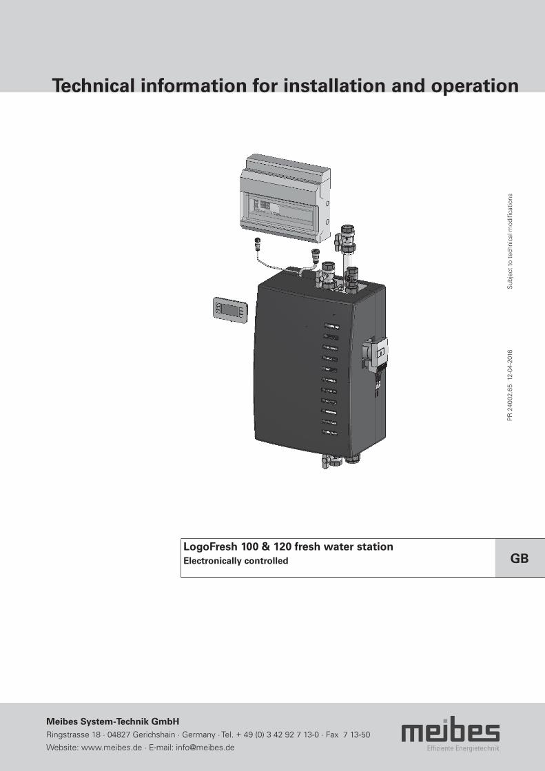
Technical information for installation and operation
Effiziente Energietechnik
Meibes System-Technik GmbHRingstrasse 18 · 04827 Gerichshain · Germany · Tel. + 49 (0) 3 42 92 7 13-0 · Fax 7 13-50
Website: www.meibes.de · E-mail: [email protected]
LogoFresh 100 & 120 fresh water stationElectronically controlled GB
PR
240
02.6
5 1
2-04
-201
6
Sub
ject
to
tech
nica
l mod
ifica
tions

2
Content
1. Safety instructions 31.1 Regulations/guidelines 31.2 Intended use 41.3 Commissioning 41.4 When working on the system 41.5 Liability 4
2. Unit description and product details 52.1 Technical data 52.2 Dimensions and connections 62.3 Design and configuration 72.4 Control panel (HMI) 82.5 Performance values 10
3. Functional description 113.1 Installation example 11
4. Hydraulic diagram 12
5. Installation 135.1 Heating connection 135.2 Domestic water connection 135.3 Electrical connections 135.4 Storage tank sensor 14
6. Flushing and filling the system 17
7. Operating instructions 187.1 Domestic water circulation 187.2 Primary and circulation pump 197.3 3-way primary mixer with servomotor 197.4 Shut-off 207.5 Manual air bleed device 207.6 Additional information regarding the installation
and commissioning 20
8. Maintenance 208.1 Heat exchanger 21
9. Diagrams 21
10. Checklist 25
3
1. Safety instructions
Read these instructions carefully before installing. The installation and initial start-up of the assembly may only be per-formed by an approved specialist company. Before starting work please familiarise yourself with all the parts and their han-dling. The application examples in these operating instructions are basic sketches only. Local laws and regulations must be taken into account.
Target group: These instructions are intended exclusively for authorised trained experts. Only trained experts are permitted to work on the heating system and domestic water, gas and electric circuits. Please follow these safety instructions faithfully to eliminate hazards, personal injury and material damage.
1.1 Regulations/guidelines
Observe the applicable accident prevention regulations, environmental regulations and legislation for the assembly, instal-lation and operation of the system. In addition, observe the applicable guidelines of the DIN, EN, DVGW, VDI and VDE (including lightning protection) and all current relevant country-specific standards, laws and guidelines. All old, newly appli-cable and unlisted but relevant regulations and standards also apply to the respective application. In addition, observe the provisions of your local energy provider. The current valid data sheets for the components used must be observed.
Extract:
Installation and design of heat generators and domestic water heaters• DIN 4753, Part 1: Water heaters, water heating systems and storage water heaters for drinking water.• DIN 18 380: Installation of heating systems and central water heating systems• DIN 18 381: Installation of gas, water and drainage pipework inside buildings.• DIN 18 421: Insulation of service installations• AV B Wa s V: Ordinance for the general conditions of water supply• DIN EN 806 ff.: Technical regulations for drinking water installation• DIN 1988 ff.: Technical regulations for drinking water installation (national supplement)• DIN EN 1717: Protection against pollution of potable water• Other standards: DIN EN 12828, DIN 50930, VDI 2035, DIN EN 14336
Electrical connection• VDE 0100: Set up of electrical equipment, earthing, protective conductors, equipotential bonding conductors.• VDE 0701: Inspection after repair, modification of electrical appliances.• VDE 0185: Protection against lightning.• VDE 0190: Specifications for the use of piping systems for protective measures in electric power installations.• VDE 0855: Installation of antennae equipment (to be applied analogously).
Additional guidelines• VDI 6002 Sheet 1: Solar heating for domestic water - General principles, system technology and use in residential buildings• VDI 6002 Sheet 2: Applications in student accommodation, retirement homes, hospitals, indoor swimming pools and
on camping sites
WARNING:Before any electrical work is carried out on the pumps or controller, these units must be deenergised in accordance with the guidelines.
GB
4
1. Safety instructions
1.2 Intended use
Appropriate use in heating and domestic water systems in accordance with the applicable DIN standards. Installing and operating the assembly incorrectly will invalidate any warranty claims. The shut-off valves may only be closed by an author-ised specialist when servicing, otherwise the safety valves will not work.
Caution:Do not make any changes to the electrical components, the design of the system or the hydraulic components! This would adversely impact on the safe function of the system.
1.3 Commissioning
Before commissioning, the system should be checked for leak tightness, correct hydraulic connection and accurate and correct electrical connections. It is also necessary to flush the system thoroughly or as required. Commissioning must be performed by trained experts and be recorded in writing. The setting values must also be recorded in writing. The technical documentation must remain with the unit.
1.4 When working on the system
The system must be disconnected from the mains and monitored to ensure that no voltage is being supplied (e.g. at the separate cut-out or a main switch). Secure the system against being restarted. (With gas-fuelled systems, close the gas shut-off valve and secure it to prevent it being opened accidentally). Repairs to components with a safety function are not permitted.
1.5 Liability
We reserve all copyrights for this document. Misuse, in particular the reproduction or disclosure to third parties is prohib-ited. These installation and operating instructions must be given to the customer. The technical team carrying out the work (e.g. installer) must clearly explain to the customer how the unit works and operates.
5
2. Unit description and product details
Product details:
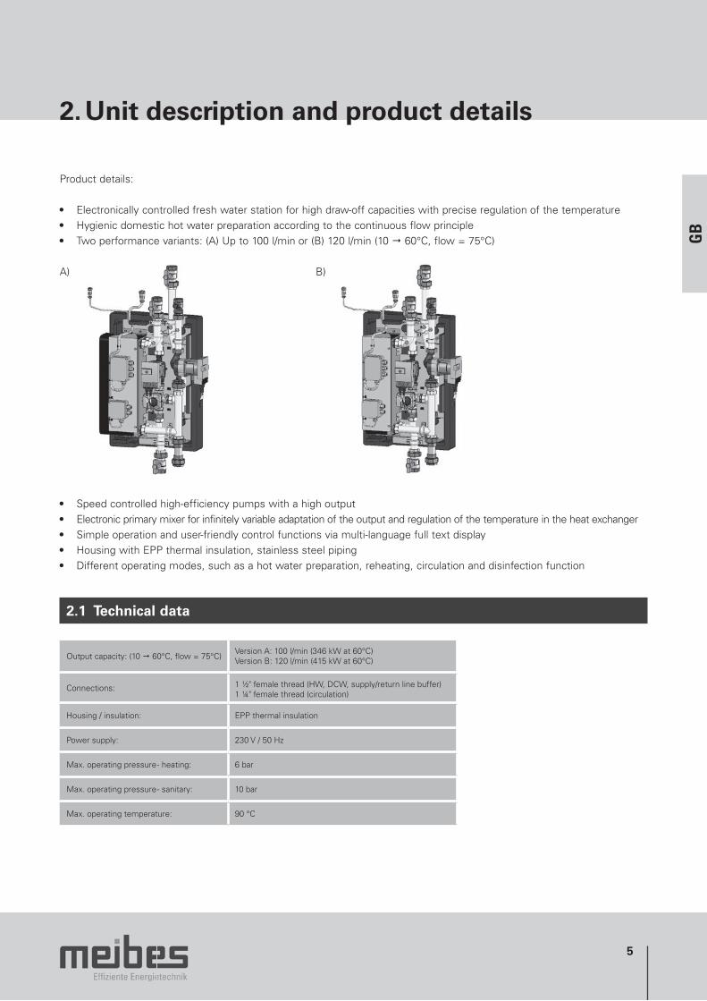
• Electronically controlled fresh water station for high draw-off capacities with precise regulation of the temperature• Hygienic domestic hot water preparation according to the continuous flow principle• Two performance variants: (A) Up to 100 l/min or (B) 120 l/min (10 60°C, flow = 75°C)
A) B)
• Speed controlled high-efficiency pumps with a high output• Electronic primary mixer for infinitely variable adaptation of the output and regulation of the temperature in the heat exchanger• Simple operation and user-friendly control functions via multi-language full text display• Housing with EPP thermal insulation, stainless steel piping• Different operating modes, such as a hot water preparation, reheating, circulation and disinfection function
2.1 Technical data
Output capacity: (10 60°C, flow = 75°C)Version A: 100 l/min (346 kW at 60°C)Version B: 120 l/min (415 kW at 60°C)
Connections: 1 ½" female thread (HW, DCW, supply/return line buffer)1 ¼" female thread (circulation)
Housing / insulation: EPP thermal insulation
Power supply: 230 V / 50 Hz
Max. operating pressure - heating: 6 bar
Max. operating pressure - sanitary: 10 bar
Max. operating temperature: 90 °C
GB

6
2. Unit description and product details
2.2 Dimensions and connections
Mounting hole centred on the base plate (Axial distance = 435 mm)
LogoFresh 100 & 120 connection:DCW, HW, flow / return buffer: 1 ½" female thread Circulation: 1 ¼" female thread (Cold water inlet without shut-off, installation of DCW safety valve and expansion vessel provided by customer)
Dimensions (H x W x D): LogoFresh 100: 1137 x 500 x 340 mmLogoFresh 120: 1137 x 530 x 340 mm (incl. shut off ball valves)
Controller: 333 x 403 x 129 mm Weight: Approx. 50 kg
7
2. Unit description and product details
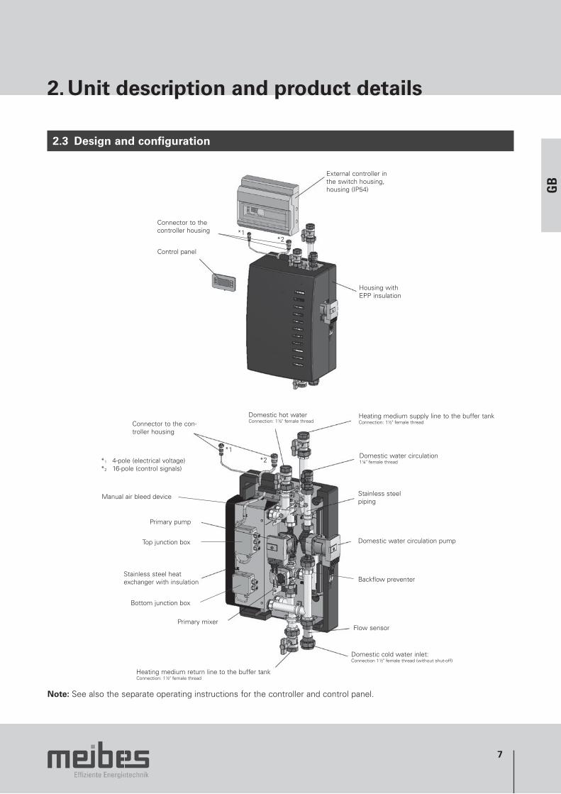
2.3 Design and configuration
Control panel
External controller in the switch housing, housing (IP54)
Housing with EPP insulation
Connector to the controller housing *1
*2
Domestic hot waterConnection: 1½" female thread
Heating medium supply line to the buffer tankConnection: 1½" female thread
Domestic water circulation1¼" female thread
Stainless steel piping
Domestic water circulation pump
Flow sensor
Domestic cold water inlet: Connection 1½" female thread (without shut-off)
Heating medium return line to the buffer tankConnection: 1½" female thread
Primary mixer
Stainless steel heat exchanger with insulation
Primary pump
Connector to the con-troller housing
Top junction box
Bottom junction box
*1
*2*1 4-pole (electrical voltage)*2 16-pole (control signals)
Backflow preventer
Manual air bleed device
Note: See also the separate operating instructions for the controller and control panel.
GB
8
2. Unit description and product details
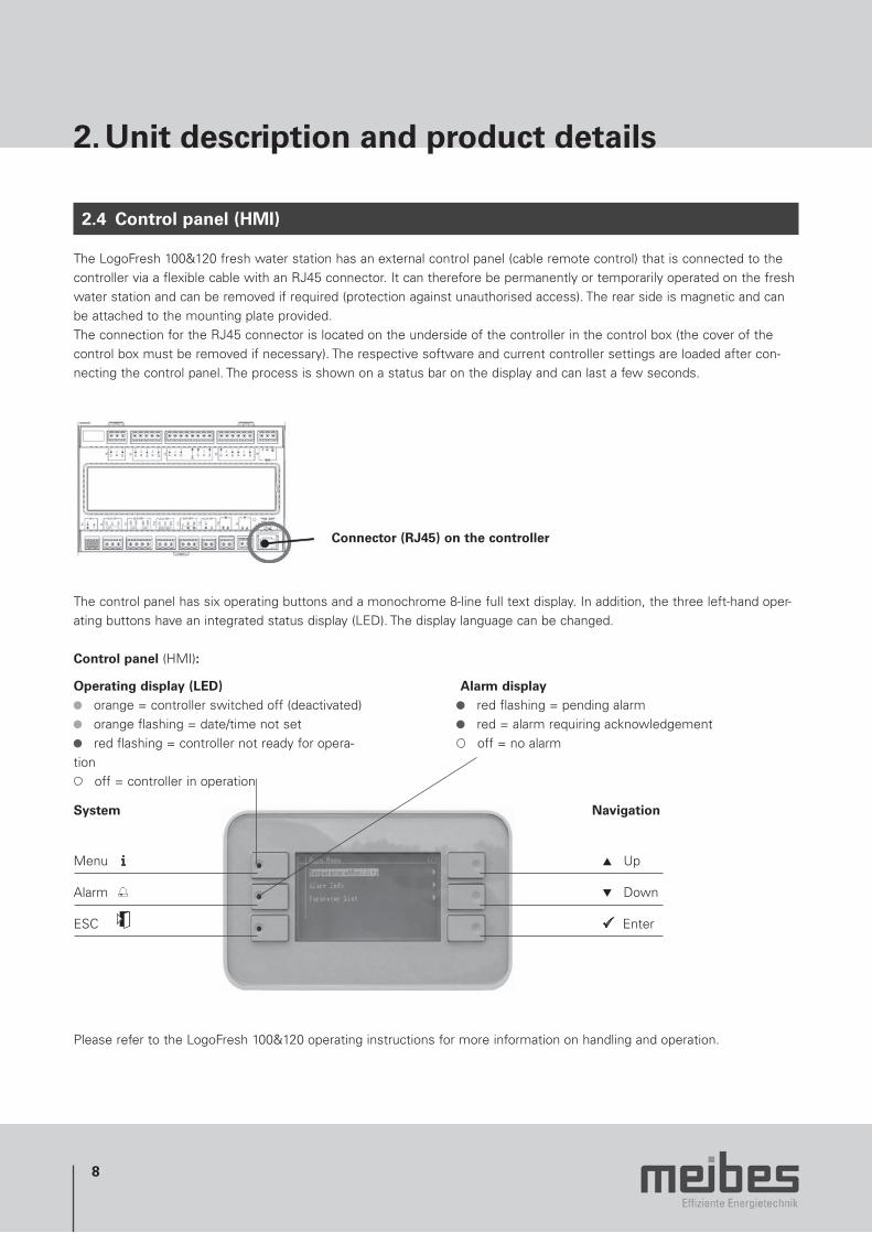
2.4 Control panel (HMI)
The LogoFresh 100&120 fresh water station has an external control panel (cable remote control) that is connected to the controller via a flexible cable with an RJ45 connector. It can therefore be permanently or temporarily operated on the fresh water station and can be removed if required (protection against unauthorised access). The rear side is magnetic and can be attached to the mounting plate provided.The connection for the RJ45 connector is located on the underside of the controller in the control box (the cover of the control box must be removed if necessary). The respective software and current controller settings are loaded after con-necting the control panel. The process is shown on a status bar on the display and can last a few seconds.
Connector (RJ45) on the controller
The control panel has six operating buttons and a monochrome 8-line full text display. In addition, the three left-hand oper-ating buttons have an integrated status display (LED). The display language can be changed.
Control panel (HMI):
Alarm display red flashing = pending alarm red = alarm requiring acknowledgement off = no alarm
Operating display (LED) orange = controller switched off (deactivated) orange flashing = date/time not set red flashing = controller not ready for opera-
tion off = controller in operation
System
Menu i
Alarm
ESC
Navigation
Up
Down
Enter
Please refer to the LogoFresh 100&120 operating instructions for more information on handling and operation.
9
2. Unit description and product details
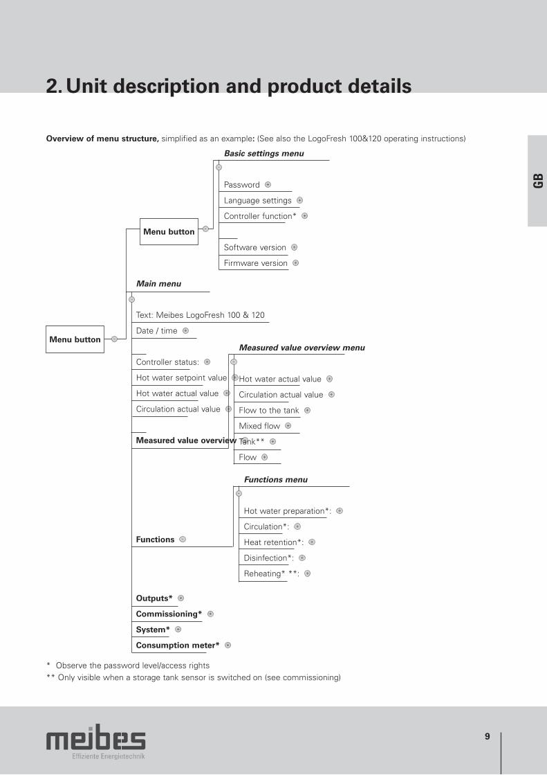
Overview of menu structure, simplified as an example: (See also the LogoFresh 100&120 operating instructions)
Menu button
Main menu
Text: Meibes LogoFresh 100 & 120
Date / time
Controller status:
Hot water setpoint value
Hot water actual value
Circulation actual value
Measured value overview
Functions
Outputs*
Commissioning*
System*
Consumption meter*
Menu button
Basic settings menu
Password
Language settings
Controller function*
Software version
Firmware version
Measured value overview menu
Hot water actual value
Circulation actual value
Flow to the tank
Mixed flow
Tank**
Flow
Functions menu
Hot water preparation*:
Circulation*:
Heat retention*:
Disinfection*:
Reheating* **:
* Observe the password level/access rights ** Only visible when a storage tank sensor is switched on (see commissioning)
GB
10
2. Unit description and product details
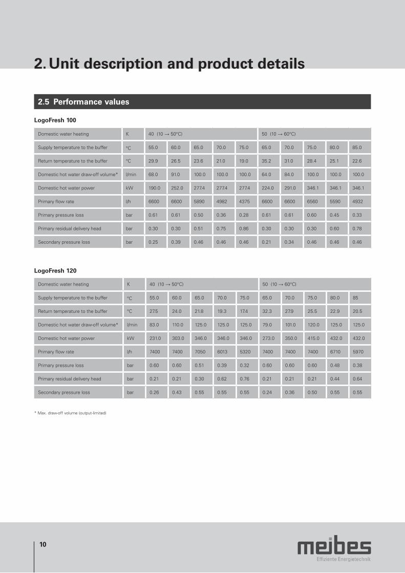
2.5 Performance values
LogoFresh 100
Domestic water heating K 40 (10 → 50°C) 50 (10 → 60°C)
Supply temperature to the buffer °C 55.0 60.0 65.0 70.0 75.0 65.0 70.0 75.0 80.0 85.0
Return temperature to the buffer °C 29.9 26.5 23.6 21.0 19.0 35.2 31.0 28.4 25.1 22.6
Domestic hot water draw-off volume* l/min 68.0 91.0 100.0 100.0 100.0 64.0 84.0 100.0 100.0 100.0
Domestic hot water power kW 190.0 252.0 277.4 277.4 277.4 224.0 291.0 346.1 346.1 346.1
Primary flow rate l/h 6600 6600 5890 4982 4375 6600 6600 6560 5590 4932
Primary pressure loss bar 0.61 0.61 0.50 0.36 0.28 0.61 0.61 0.60 0.45 0.33
Primary residual delivery head bar 0.30 0.30 0.51 0.75 0.86 0.30 0.30 0.30 0.60 0.78
Secondary pressure loss bar 0.25 0.39 0.46 0.46 0.46 0.21 0.34 0.46 0.46 0.46
LogoFresh 120
Domestic water heating K 40 (10 → 50°C) 50 (10 → 60°C)
Supply temperature to the buffer °C 55.0 60.0 65.0 70.0 75.0 65.0 70.0 75.0 80.0 85
Return temperature to the buffer °C 27.5 24.0 21.8 19.3 17.4 32.3 27.9 25.5 22.9 20.5
Domestic hot water draw-off volume* l/min 83.0 110.0 125.0 125.0 125.0 79.0 101.0 120.0 125.0 125.0
Domestic hot water power kW 231.0 303.0 346.0 346.0 346.0 273.0 350.0 415.0 432.0 432.0
Primary flow rate l/h 7400 7400 7050 6013 5320 7400 7400 7400 6710 5970
Primary pressure loss bar 0.60 0.60 0.51 0.39 0.32 0.60 0.60 0.60 0.48 0.38
Primary residual delivery head bar 0.21 0.21 0.30 0.62 0.76 0.21 0.21 0.21 0.44 0.64
Secondary pressure loss bar 0.26 0.43 0.55 0.55 0.55 0.24 0.36 0.50 0.55 0.55
* Max. draw-off volume (output-limited)
11
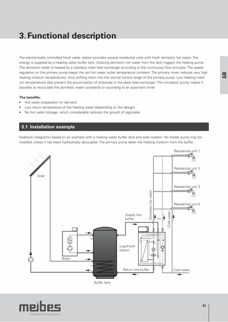
3. Functional description
The electronically controlled fresh water station provides several residential units with fresh domestic hot water. The energy is supplied by a heating water buffer tank. Drawing domestic hot water from the tank triggers the heating pump. The domestic water is heated by a stainless steel heat exchanger according to the continuous flow principle. The speed regulation on the primary pump keeps the set hot water outlet temperature constant. The primary mixer reduces very high heating medium temperatures, thus shifting them into the normal control range of the primary pump. Low heating medi-um temperatures also prevent the accumulation of limescale in the plate heat exchanger. The circulation pump makes it possible to recirculate the domestic water constantly or according to an automatic timer.
The benefits:• Hot water preparation on demand• Low return temperature of the heating water (depending on the design)• No hot water storage, which considerably reduces the growth of legionella
3.1 Installation example
Hydraulic integration based on an example with a heating water buffer tank and solar system: No feeder pump may be installed unless it has been hydraulically decoupled. The primary pump takes the heating medium from the buffer.
Residential unit 4
Solar
Boiler
Buffer tank
Supply line buffer
LogoFreshstation
Return line buffer
Dom
estic
hot
wat
er
Z
Col
d w
ater
Residential unit 1
Residential unit 2
Residential unit 3
Cold water
GB

12
4. Hydraulic diagram
Legend
1 Stainless steel heat exchanger with insulation2 Primary pump3 Primary mixer with rapid actuator 4 Domestic water circulation pump5 Domestic hot water temperature sensor6 Heating-circuit water temperature sensor (mixed)7 Heating-circuit water temperature sensor (flow)8 Sanitary circulation temperature sensor9 Bleed device10 Backflow preventer11 Flow meter12 Fill and drain ball valve, ½" external thread13 Shut-off ball valve14 Controller
A Domestic hot water outletB Heating medium supply line to the buffer tank C Domestic water circulation returnD Heating medium return line to the buffer tank E Domestic cold water connection

13
5. Installation
Please follow the safety instructions contained in this document during installation! Installing and operating the stations incorrectly will invalidate any warranty claims. Hazards resulting from adjoining masonry components must be avoided. Free access to the station and connection lines must be ensured. Make sure the connection to the station is tension-free. The station should be installed on a dry wall that can take the load and directly adjacent to a heating water buffer tank where possible.
Note:• Heat exchanger water capacity > 3 litres• Domestic water safety valve not supplied with the station• Dirt traps to protect the system are provided in the station inlet if required
5.1 Heating connection
Once the station has been installed correctly, connect the heating circuit.
Connection D 1 ½" female thread Heating medium return line to the buffer tankConnection B 1 ½" female thread Heating medium supply line to the buffer tank
Max. permissible operating pressure 6 barMax. permissible operating temperature: 90°C
5.2 Domestic water connection
Please note:The safety fuse on the cold water side must comply with DIN EN 806, DIN 1988 and DIN EN 1717, i.e. with a safety group and expansion vessel if necessary.
Connect the domestic water circuit once the station has been installed correctly.
Connection A 1 ½" female thread Hot water outletConnection E 1 ½" female thread Cold water inletConnection C 1 ¼" female thread Circulation return
Max. permissible operating pressure: 10 barMax. permissible operating temperature: 90°C
5.3 Electrical connections
The system is connected to the mains supply (230 V/50 Hz AC) by the customer using the connection terminals provided. Comply with the energy utility company regulations! The power cable must be connected to the controller by the customer (see terminal diagram on page 15). This electric circuit must be protected by a 10 A circuit breaker. The connectors are used to connect the station and controller. The enclosed cable relief should be attached to the controller housing and used!
GB
14
5. Installation
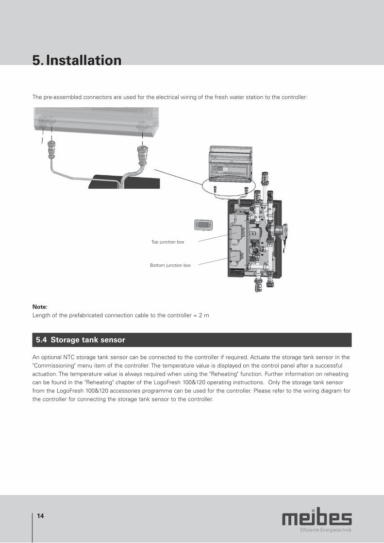
The pre-assembled connectors are used for the electrical wiring of the fresh water station to the controller:
Top junction box
Bottom junction box
Note:Length of the prefabricated connection cable to the controller = 2 m
5.4 Storage tank sensor
An optional NTC storage tank sensor can be connected to the controller if required. Actuate the storage tank sensor in the "Commissioning" menu item of the controller. The temperature value is displayed on the control panel after a successful actuation. The temperature value is always required when using the "Reheating" function. Further information on reheating can be found in the "Reheating" chapter of the LogoFresh 100&120 operating instructions. Only the storage tank sensor from the LogoFresh 100&120 accessories programme can be used for the controller. Please refer to the wiring diagram for the controller for connecting the storage tank sensor to the controller.
15
5. Installation
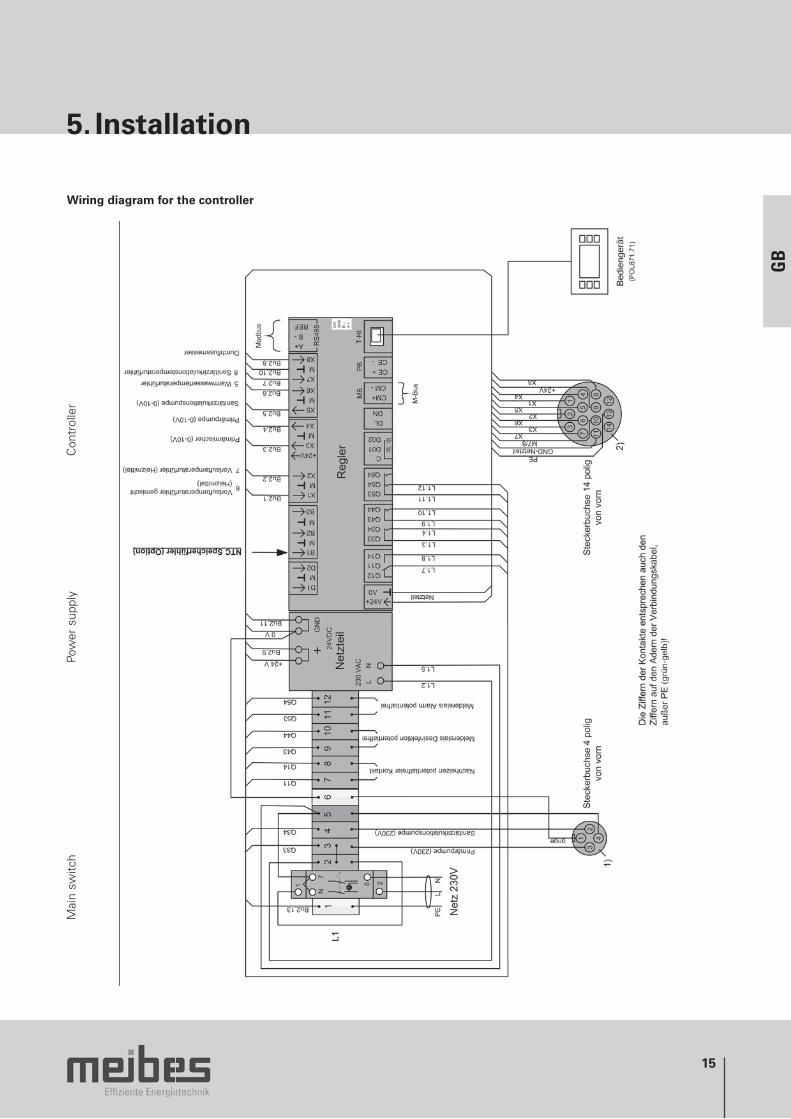
Wiring diagram for the controller
Mai
n sw
itch
Pow
er s
uppl
yC
ontr
olle
r
GB
16
5. Installation
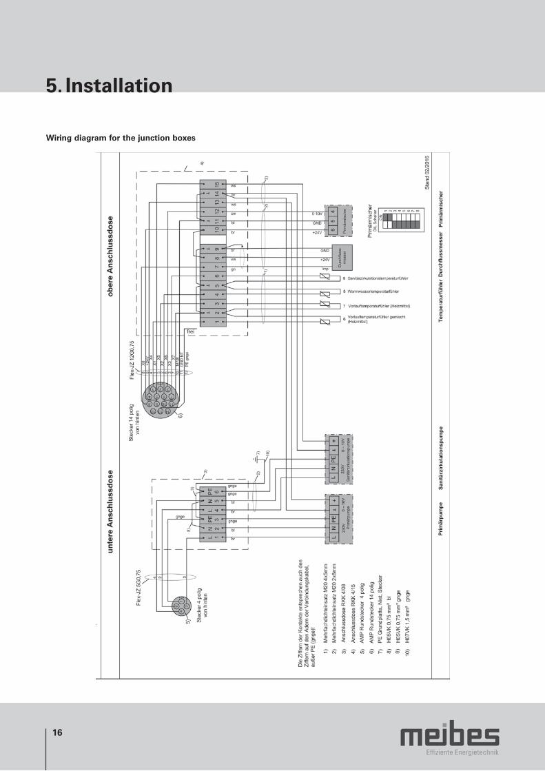
Wiring diagram for the junction boxes
17
6. Flushing and filling the system
• Before starting, open all shut-offs and set the primary mixer servomotor manually to 50% in manual mode (refer to the manufacturer's documentation) so that all lines are open.
• The flushing, filling and bleeding must be carried out professionally and correctly.• Flush the system carefully before filling.• Check all connections and repair them if necessary.• Ensure all threaded joints are screwed tightly.• Once the system has been filled, bleed the station and refill the heating system as required.• Use the bleed devices on the station.• The primary mixer servomotor must be manually reset to automatic upon completion.
GB

18
7. Operating instructions
7.1 Domestic water circulation
The domestic water circulation system is used to provide a constant supply of hot water to the taps and to flush the domestic water pipes ( growth of legionella). Please ensure you comply with the relevant technical regula-tions and guidelines.
A check valve is installed on the pressurised side of the circulation pump on the domestic water side in order to prevent unwanted circulation. The controller can be used to control the domestic water circulation. The factory setting must be dependent on the object adapted.
DN32 backflow preventer• in the domestic water circulation• with 2" seal• The illustration shows the installation
position and the flow direction of the return inhibitor
19
GB
7. Operating instructions
7.2 Primary and circulation pump
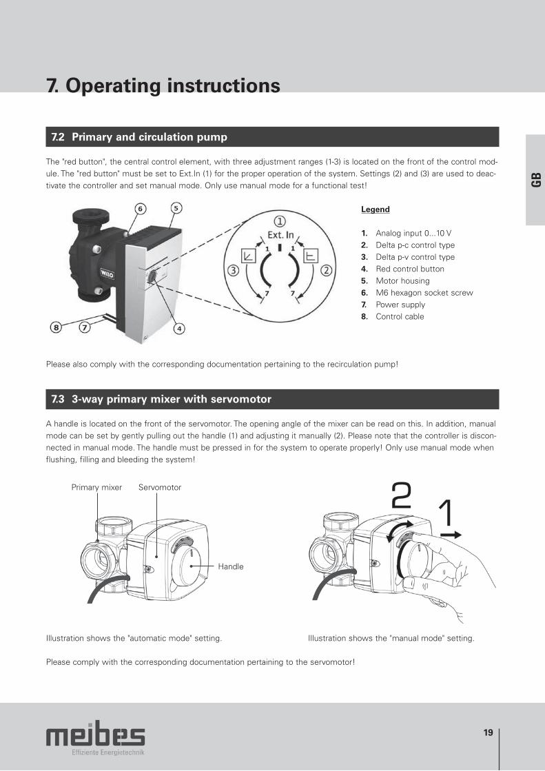
The "red button", the central control element, with three adjustment ranges (1-3) is located on the front of the control mod-ule. The "red button" must be set to Ext.In (1) for the proper operation of the system. Settings (2) and (3) are used to deac-tivate the controller and set manual mode. Only use manual mode for a functional test!
Legend
1. Analog input 0...10 V 2. Delta p-c control type 3. Delta p-v control type 4. Red control button 5. Motor housing 6. M6 hexagon socket screw 7. Power supply 8. Control cable
Please also comply with the corresponding documentation pertaining to the recirculation pump!
7.3 3-way primary mixer with servomotor
A handle is located on the front of the servomotor. The opening angle of the mixer can be read on this. In addition, manual mode can be set by gently pulling out the handle (1) and adjusting it manually (2). Please note that the controller is discon-nected in manual mode. The handle must be pressed in for the system to operate properly! Only use manual mode when flushing, filling and bleeding the system!
Primary mixer Servomotor
Handle
Illustration shows the "automatic mode" setting. Illustration shows the "manual mode" setting.
Please comply with the corresponding documentation pertaining to the servomotor!
20
7. Operating instructions
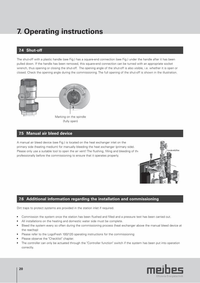
7.4 Shut-off
The shut-off with a plastic handle (see Fig.) has a square-end connection (see Fig.) under the handle after it has been pulled down. If the handle has been removed, this square-end connection can be turned with an appropriate socket wrench, thus opening or closing the shut-off. The opening angle of the shut-off is also visible, i.e. whether it is open or closed. Check the opening angle during the commissioning. The full opening of the shut-off is shown in the illustration.
Marking on the spindle (fully open)
7.5 Manual air bleed device
A manual air bleed device (see Fig.) is located on the heat exchanger inlet on the primary side (heating medium) for manually bleeding the heat exchanger (primary side). Please only use a suitable tool to open the air vent! The flushing, filling and bleeding of the system must be carried out professionally before the commissioning to ensure that it operates properly.
7.6 Additional information regarding the installation and commissioning
Dirt traps to protect systems are provided in the station inlet if required.
• Commission the system once the station has been flushed and filled and a pressure test has been carried out. • All installations on the heating and domestic water side must be complete.• Bleed the system every so often during the commissioning process (heat exchanger above the manual bleed device at
the rear/top)• Please refer to the LogoFresh 100/120 operating instructions for the commissioning• Please observe the "Checklist" chapter.• The controller can only be actuated through the "Controller function" switch if the system has been put into operation
correctly.

21
GB
8. Maintenance
The maintenance and service must be performed by a trained expert.
8.1 Heat exchanger
Note:If the water is hard, limescale deposits can build up on hot areas of the heat exchanger at high water temperatures. These should be removed at regular intervals by appropriate means (e.g. flushing). Only use substances approved for use with domestic water and heating water.
Information regarding the hardness of the domestic water:The propensity for natural water to form limescale deposits depends, among other things, on various factors such as the concentration of calcium and magnesium salts, the pH value and the temperature. If what is known as the lime-carbonic acid balance has been disturbed by an increase in the pH value and/or the temperature, the calcium carbonate precipitates in the form of calcite crystals. The applicable standards and corresponding technical regulations (e.g. DIN and DVGW) must therefore be observed.
Hardness range Millimoles of calcium carbonate/ litre
Degree of hardness in °dH
Risk of limescale deposits depending on the domestic water temperature
< 60°C 60 – 70°C > 70°C
Soft < 1.5 < 8.4 low low low
Average 1.5 – 2.5 8.4 – 14 low low medium
Hard > 2.5 > 14 low medium high
Note:Request a water analysis from the local utility companies for testing in the case of known risks or contested water quality.

22
9. Diagrams
LogoFresh 100 performance data Required heating-circuit water flow rates when heating domestic water by 50 K (10 at 60°C)
Hot domestic water draw-off volume in l/min
Power limit
Hea
ting-
circ
uit
wat
er t
empe
ratu
res
(flo
w)
Hea
ting-
circ
uit
wat
er f
low
rat
e in
l/h
LogoFresh 100 performance dataReturn temperature when heating domestic water by 50 K (10 at 60 °C)
Hot domestic water draw-off volume in l/min
Ret
urn
tem
pera
ture
in °
C
Hea
ting-
circ
uit
wat
er t
empe
ratu
res
(flo
w)

23
9. Diagrams
LogoFresh 120 performance dataRequired heating-circuit water flow rates when heating domestic by 50 K (10 at 60°C)
Hot domestic water draw-off volume in l/min
Power limit
Hea
ting-
circ
uit
wat
er t
empe
ratu
res
(flo
w)
Hea
ting-
circ
uit
wat
er f
low
rat
e in
l/h
LogoFresh 100 performance dataReturn temperature when heating domestic water by 50 K (10 at 60 °C)
Hot domestic water draw-off volume in l/min
Hea
ting-
circ
uit
wat
er t
empe
ratu
res
(flo
w)
Ret
urn
tem
pera
ture
in °
C
GB
24
9. Diagrams
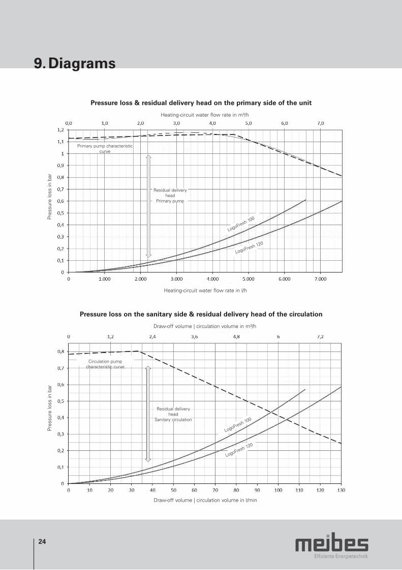
Pressure loss & residual delivery head on the primary side of the unit
Heating-circuit water flow rate in l/h
Heating-circuit water flow rate in m³/h
Primary pump characteristiccurve
Pres
sure
loss
in b
ar
Residual delivery head
Primary pump
LogoFresh 100
LogoFresh 120
Pressure loss on the sanitary side & residual delivery head of the circulation
Draw-off volume | circulation volume in l/min
Draw-off volume | circulation volume in m³/h
Circulation pump characteristic curve
Pres
sure
loss
in b
ar
Residual delivery head
Sanitary circulation
LogoFresh 100
LogoFresh 120
25
GB
10. Checklist
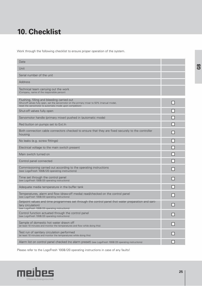
Work through the following checklist to ensure proper operation of the system.
Date
Unit
Serial number of the unit
Address
Technical team carrying out the work(Company, name of the responsible person)
Flushing, filling and bleeding carried out(Shut-off valves fully open, set the servomotor on the primary mixer to 50% (manual mode), reset the servomotor to automatic mode upon completion)
Shut-off valves fully open
Servomotor handle (primary mixer) pushed in (automatic mode)
Red button on pumps set to Ext.In
Both connection cable connectors checked to ensure that they are fixed securely to the controller housing
No leaks (e.g. screw fittings)
Electrical voltage to the main switch present
Main switch turned on
Control panel connected
Commissioning carried out according to the operating instructions(see LogoFresh 100&120 operating instructions)
Time set through the control panel(see LogoFresh 100&120 operating instructions)
Adequate media temperature in the buffer tank
Temperatures, alarm and flow (draw-off media) read/checked on the control panel(see LogoFresh 100&120 operating instructions)
Setpoint values and time programmes set through the control panel (hot water preparation and sani-tary circulation)(see LogoFresh 100&120 operating instructions)
Control function actuated through the control panel(see LogoFresh 100&120 operating instructions)
Sample of domestic hot water drawn off(at least 10 minutes and monitor the temperatures and flow while doing this)
Test run of sanitary circulation performed(at least 10 minutes and monitor the temperatures while doing this)
Alarm list on control panel checked (no alarm preset) (see LogoFresh 100&120 operating instructions)
Please refer to the LogoFresh 100&120 operating instructions in case of any faults!

26
Effiziente Energietechnik
Meibes System-Technik GmbHRingstrasse 18 · 04827 Gerichshain · Germany · Tel. + 49 (0) 3 42 92 7 13-0 · Fax 7 13-50
Website: www.meibes.de · E-mail: [email protected]
Contact information
27
Notes