study of horizontally polarized omnidirectional microstrip ... · 108 kun wei, jian-ying li, ling...
TRANSCRIPT

RADIOENGINEERING, VOL. 26, NO. 1, APRIL 2017 107
DOI: 10.13164/re.2017.0107 ELECTROMAGNETICS
Study of Horizontally Polarized Omnidirectional Microstrip Antenna Arrays
Kun WEI, Jian-Ying LI, Ling WANG, Rui XU
School of Electronics and Information, Northwestern Polytechnical University, 710072 Xi’an, Shannxi, China
[email protected], [email protected], [email protected], [email protected]
Submitted September 12, 2016 / Accepted January 20, 2017
Abstract. This paper presents two microstrip antenna arrays for horizontally polarized (HP) omnidirectional application, namely rectangular patch antenna array and H-shaped patch antenna array. There are eight patch ele-ments placed with back-to-back structure, four patch ele-ments on each side. Antenna arrays are fed by a split eight power divider. The H-shaped patch antenna array has better omnidirectional performance than rectangular patch antenna array. The H-shaped antenna array is fabricated and measured. Both simulated and measured results show that the bandwidth of the designed H-shaped antenna ar-ray is 36 MHz with a center frequency 2.35 GHz. Horizon-tally polarized gains are greater than 7 dBi over the reso-nant band (S11 < −10 dB), while the cross-polarization level is less than −25 dB. The proposed H-shaped antenna array has high directivity (half-power beam-width is only 20 deg) and good omnidirectional performance (gain vari-ation less than 1.5 dBi) at the center frequency.
Keywords Antenna array, horizontal polarization, omnidirec-tional radiation pattern, microstrip antenna
1. Introduction Omnidirectional antenna array has been widely used
in mobile communication, indoor radio, and wireless LAN systems because of their better performance in multiple paths environment. The need for horizontally polarized (HP) omnidirectional antenna array is growing considera-bly. However, it is still a challenge to design a HP omnidi-rectional antenna array with high gain and high directivity, which is of great importance in many applications.
Some HP omnidirectional antenna arrays have been reported. In [1], [2], HP omnidirectional antenna array with zero-phase-shift line loop elements is presented, which has a gain greater than 6 dBi and a gain variation less than ±2.5 dBi. The HP omnidirectional dipole array antennas with gain variations less than 2 dBi are presented in [3], [4]. The planar dipole array configuration is designed by using
back-to-back dipole elements with omnidirectional pattern, and is constructed by printing on both sides of a dielectric substrate. In [5], a HP omnidirectional antenna utilizing stacked octagonal dipole array is designed from brass sheet. It has a gain of 1.1 dBi to 2.3 dBi along the frequency range.
Slot antenna arrays for HP omnidirectional applica-tion are also studied. In [6], [7], an omnidirectional array of broad wall slot doublets in a rectangular waveguide is presented. An HP omnidirectional slot antenna array is proposed in [8]. The antenna comprises two slot-elements that cut onto the ground plane on a substrate. The maxi-mum gain is 5.5 dBi, and the gain variation is within ±1.5 dBi. In [9], an HP omnidirectional antenna using cir-cular array of axial slot on cylinder is presented. The maxi-mum gain is 5.63 dBi and the gain variation is less than 2 dBi. In [10], an HP slot array on a coaxial cylinder is achieved by arranging slots with opposite lean angles. However, slot antennas or arrays are large in size, heavy in weight, and difficult to fabricate.
An HP omnidirectional planar loop antenna that em-ploys an artificial μ-negative transmission line (MNG-TL), which is designed by periodically loaded parallel-plate lines, is proposed in [11]. The four-element MNG-TL loop antenna array offers HP omnidirectional radiation patterns with enhanced gain of 6.5 to 7.9 dBi and the gain variation in the azimuth plane is below 2.1 dBi. A periodic leaky-wave antenna with HP omnidirectional pattern is proposed in [12]. The structure formed by 16 unit cell is developed at the 2.4 GHz band, which offers a HP omnidirectional radiation pattern with enhanced gain of 9.9 dBi to 10.6 dBi and a gain variation less than 1.8 dBi.
Though some HP omnidirectional antenna arrays have been reported, no previous works in the open litera-ture (to the best of the present authors' knowledge) are available concerning the microstrip antenna array with HP omnidirectional radiation pattern. There are a lot works about omnidirectional planar microstrip antennas presented in [13–15], all those works focus on how to obtain omnidi-rectional radiation pattern, none of them are HP microstrip antenna array with high gain and high directivity. Antenna in [16] is omnidirectional horizontally polarized, but the antenna gain is only about 2 dBi.
108 KUN WEI, JIAN-YING LI, LING WANG, ET AL., STUDY OF HORIZONTALLY POLARIZED OMNIDIRECTIONAL MICROSTRIP …
This paper presents two new HP omnidirectional mi-crostrip antenna arrays, namely rectangular patch antenna array and H-shaped patch antenna array. The designed antenna arrays have back-to-back structure, which consists of 8 patch elements. There are 4 patch elements on each side. The radiation model of the back-to-back antenna array is studied, and the directivity formula on main radia-tion plane is obtained. The H-shaped patch [17] antenna array has better omnidirectional radiation pattern than the rectangular patch antenna array. Ansoft HFSS is applied to design and simulate the antenna arrays for the purpose of optimizing the omnidirectional characteristic, drawing the better technical parameters. The proposed H-shaped an-tenna array is fabricated and measured. Both measured and simulated results are presented and compared.
The remaining parts of this paper are organized as fol-lows. In Sec. 2, the study for the antenna arrays structure is presented. The ways to achieve better omnidirectional radiation are given in Sec. 3. Section 4 shows the simula-tion and measurement results of the H-shaped antenna array. The conclusion is given in Sec. 5.
2. Antenna Array Design The proposed antenna arrays consist of four layers as
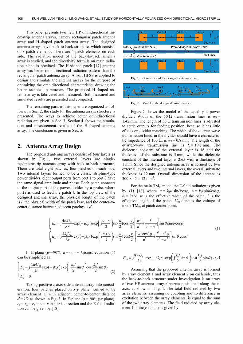
shown in Fig. 1, two external layers are single-feedmicrostrip antenna array with back-to-back structure. There are total eight patches, four patches on each side. Two internal layers formed to be a classic stripline-type power divider, eight output ports from port 1 to port 8 have the same signal amplitude and phase. Each patch connects to the output port of the power divider by a probe, where port i is used to feed the patch i. In the top view of the designed antenna array, the physical length of the patch is l, the physical width of the patch is w, and the center-to-center distance between adjacent patches is d.
Fig. 1. Geometries of the designed antenna array.
Fig. 2. Model of the designed power divider.
Figure 2 shows the model of the equal-split power divider. Width of the 50 Ω transmission lines is w1 = 1.42 mm. The length of 50 Ω transmission lines is adjusted to settle outputs for feeding position, because it has little effects on divider matching. The width of the quarter-wave transmission lines, in the divider should have a characteris-tic impedance of 100 Ω, is w2 = 0.8 mm. The length of the quarter-wave transmission line is lg = 19.1 mm. The dielectric constant of the external layer is 16 and the thickness of the substrate is 5 mm, while the dielectric constant of the internal layer is 2.65 with a thickness of 1 mm. Since the designed antenna array is formed by two external layers and two internal layers, the overall substrate thickness is 12 mm. Overall dimension of the antenna is 300 × 45 × 12 mm3.
For the main TM01 mode, the E-field radiation is given by (1) [18] where u = k0w sincos, v = k0l sincos, k0 = 2/, w is the effective width of the patch, l is the effective length of the patch. U01 denotes the voltage of mode TM01 at patch corner point.
2 20 01
θ 0 2 2 2
2 2 2 20 01
φ 0 2 2 2
4j exp j exp j sin( )cos( ) sin sin cos
2 2 2
4 cos sinj exp j exp j sin( )cos( ) sin cos
2 2 2
k U u v u v w lE k r
r u v
k U u v u v w lE k r
r u v
(1)
In E-plane ( =90°): u = 0, v = k0lsin, equation (1)
can be simplified as
01 0 0θ 0
φ
2j exp j exp j sin cos( sin )
2 2
0
wU k l k lE k r
r
E
(2)
Taking positive z-axis side antenna array into consid-eration, four patches placed on x-y plane, formed to be array element 1, with adjacent center-to-center distance d = λ/2 as shown in Fig. 3. In E-plane (φ = 90°, y-z plane), r1 = r2 = r3 = r4 = r in z-axis direction and the E-field radia-tion can be given by [18]:
01 0 01θ 0 1
1
8j exp j exp j sin cos( sin )
2 2
wU k l k lE k r
r
. (3)
Assuming that the proposed antenna array is formed by array element 1 and array element 2 on each side, thus the back-to-back structure under investigation is an array of two HP antenna array elements positioned along the z-axis, as shown in Fig. 4. The total field radiated by two array elements, assuming no coupling and no difference in excitation between the array elements, is equal to the sum of the two array elements. The field radiated by array ele-ment 1 in the y-z plane is given by

RADIOENGINEERING, VOL. 26, NO. 1, APRIL 2017 109
Fig. 3. Uniform four-antenna linear antenna array in x-z
plane.
Fig. 4. Uniform linear antenna arrays in y-z plane.
01 0 0θ 0 1
1
8(1) j exp j exp j sin cos( sin )
2 2
wU k l k lE k r
r
.(4)
Since the array element 2 rotates 180° around x-axis compared to array element 1, field radiated by array element 2 in y-z plane is given by
θ
01 0 00 2
2
2
8j exp j exp j sin( ) cos( sin( )).
2 2
E
wU k l k lk r
r
(5)
As in this case, d’= 0, so r1’= r2’= r’. The total field radiated by the pair of array elements is given by
θ θ θ
01 00
0 0
201 00
1 2
8j exp cos( sin )
' 2
exp j sin exp j sin2 2
16j exp cos ( sin ).
' 2
E E E
wU k ljk r
r
k l k l
wU k ljk r
r
(6)
Thus, for the two array elements of constant ampli-tude, the total approximate formula for directivity as a function of the directional angles in y-z plane is repre-sented by:
4 00 cos ( sin )
2
k lD D
(7)
where k0 = 2π/λ, D0 is the maximum directivity. Different normalized pattern can be obtained with given different l. Suggesting that the antenna pattern roundness is
R = Dmin / Dmax, and the gain variation around the E-plane is V = |10logR| dBi, so the directivity in y-z plane can be given by:
4 400 0cos ( sin ) cos (π sin )
2
k lD D D g (8)
where l = gλ. In general, the effective length of the patch is less than λ/2, so 0 < g < 0.5. Since the effective length is a little bit longer than the physical length, and the effective length is in proportion to the physical length, it is tenable to replace the effective length with the physical length in (8) at the same frequency.
3. Achieving Better Omnidirectional Performance As omnidirectivity is proportional to patch length, it
is efficient to reduce the patch length for getting better omnidirectional radiation pattern when antenna arrays have the same resonant frequency. There are mainly two ways to decrease the patch length while keeping the antenna array work at the same frequency. One is increasing the substrate dielectric constant, the other way is using H-shaped patch to replace the rectangular patch.
3.1 Increasing Substrate Dielectric Constant In order to verify the accuracy of (8) and achieve bet-
ter omnidirectional performance for directivity in y-z plane of the proposed antenna array, comparisons between HFSS simulated and formula calculated gain variation around y-z plane with different patch length are made. To simplify the simulation process, the power divider is removed from the designed antenna array, the patches are fed by 8 ports with the same signal amplitude and phase.
The normalized radiation patterns of HFSS simulated and calculated by (8) in y-z plane are illustrated in Fig. 5 when tuning substrate dielectric constant. Length l1 of patch a in Fig. 5(a) is 29.2 mm when substrate dielectric constant is 4. Length l2 of patch b in Fig. 5(b) is 23.4 mm when substrate dielectric constant is 6. Length l3 of patch c in Fig. 5(c) is 20.4 mm when dielectric constant is 8. Length l4 of patch d in Fig. 5(d) is 16.3 mm when dielectric constant is 12. The antenna arrays with different patch lengths have the same resonant frequency of 2.35 GHz.
Table I summarizes the specified numeric comparison of gain variation calculated by (8) and HFSS by given different patch length. Length l of patch a is 29.2 mm, which is nearly 0.229 λ, so g = 0.229. Approximate equa-tion for directivity is D = D0 cos4(π g sinθ), thus Dmax= D0 and Dmin = 0.32 D0, so antenna pattern roundness R = Dmin / Dmax = 0.32 and calculated gain variation is V = |10logR| ≈ 4.9 dBi. By using the same procedure, gain variation of antenna array with other patch physical length is calculated. Comparison of calculated gain variations (8) with HFSS simulated ones against substrate dielectric con-stant are plotted in Fig. 6.

110 KUN WEI, JIAN-YING LI, LING WANG, ET AL., STUDY OF HORIZONTALLY POLARIZED OMNIDIRECTIONAL MICROSTRIP …
Fig. 5. Normalized formula calculated and HFSS calculated
radiation pattern on E-plane when tuning dielectric constant: (a) εr = 4, (b) εr = 6, (c) εr = 8, (d) εr = 12.
Fig. 6. Comparison between formula calculated gain
variations and HFSS calculated ones when tuning substrate dielectric constant.
Dielectric constant
Length l (mm)
g Formula
Calculated (dBi)
HFSS simulated
(dBi)
OptimalS11(dB)
4 29.2 0.229 4.9 3.7 −23 6 23.4 0.182 3.0 1.9 −25 8 20.4 0.161 2.3 1.3 −21 12 16.3 0.128 1.4 1.0 −24
Tab. 1. Comparison of the gain variation when tuning substrate dielectric constant.
Table 1 and Figure 6 summarize the gain variation on main radiation plane against substrate dielectric constant. From Tab. 1 and Fig. 6, the following results are clear: (a) The back-to-back structure microstrip antenna array radiates omnidirectional radiation pattern; (b) By increas-ing the substrate dielectric constant, the gain variation on the main radiation plane decreases. In general, the patch length can be decreased by increasing the substrate dielec-tric constant when the antenna arrays have the same reso-nant frequency. In this way, the gain variation of the omni-directional pattern can be decreased, better omnidirectional characteristic is achieved. The optimized parameter values of the rectangular patch antenna array at 2.35 GHz are:
w1 =1.42 mm, w2 = 0.8 mm, lg = 19.1 mm and l = w = 20.4 mm, substrate dielectric constant 8 and thickness 5 mm.
However, the increased dielectric constant often brings decreased bandwidth, increased losses (lower effi-ciency) and matching problems. It is important to select a proper substrate dielectric constant for achieving better antenna performances.
3.2 Using H-shaped Patch
As omnidirectivity is proportional to patch length, it is efficient to reduce the patch length for getting better omnidirectional radiation pattern. The H-shaped patch antenna has smaller dimension than that of the rectangular patch antenna when they resonate in the same frequency. Using H-shaped patch can achieve better omnidirectional performance without degrading the antenna array perfor-mance. Figure 7 shows the physical dimensions of single H-shaped patch antenna. When the H-shaped antenna reso-nates at 2.35 GHz, the optimized parameter values are: a = 2.5 mm, b = 9 mm, s = 13 mm, w = 17 mm, l = 20 mm, dielectric constant 10 and thickness 5 mm.
Table 2 and Figure 8 summarize the specified numeric comparison of improved gain variation by using H-shaped patch antenna. There are four kinds of substrates with different dielectric constant from No. 1 to No. 4, and each substrate is used to design rectangular patch antenna array and H-shaped patch antenna array. The antenna arrays have the same resonant frequency of 2.35 GHz. For example, taking dielectric constant of 6, the length l of H-shaped patch and rectangular patch are 20 mm and 23.3 mm. The formula calculated gain variations around y-z plane are 2.2 dBi and 3.0 dBi, respectively. Length of the H-shaped patch is 14.2 % shorter than that of the rectangular patch. The improved gain variation on main radiation plane is 1.2 dBi (formula calculated) and 0.8 dBi (HFSS simulated). The formula calculated improved gain variations of patch No. 1 to No. 4 are 1.3 dBi, 1.2 dBi, 0.8 dBi and 0.4 dBi. HFSS simulated improved gain varia-tions from patch No. 1 to No. 4 are 1.13 dBi, 0.8 dBi, 0.55 dBi and 0.32 dBi. In Tab. 2 and Figure 8, it is clearly shown that using H-shaped patch antenna to replace rectan-gular patch antenna is efficient for achieving better omnidirectional radiation pattern.
Fig. 7. Model of the H-shaped patch antenna.

RADIOENGINEERING, VOL. 26, NO. 1, APRIL 2017 111
Fig. 8. The H-shaped antenna array improved gain variation comparison between formula and HFSS calculated results when tuning substrate dielectric constant.
Dielectric constant 4 6 8 12 H-shaped Length l (mm) 25.5 20 18.1 14.8 Rectangular patch l (mm) 29.2 23.3 20.5 16.3 Reduced Length 10.90% 14.20% 11.70% 9.20% Improved gain variation by HFSS simulator (dBi)
1.13 0.8 0.55 0.32
Improved gain variation by formula (dBi)
1.3 1.2 0.8 0.4
Optimal S11 (dB) of the H-shaped antenna array
−25 −23 −26 −25
Tab. 2. Comparison of the gain variation by using H-shaped patch when tuning substrate dielectric constant.
4. Simulation and Measurement The H-shaped antenna array is fabricated based on the
optimized simulation. The optimized parameter values are: a = 2.5 mm, b = 9 mm, s = 13 mm, w = 17 mm, l = 20 mm, w1 = 1.42 mm, w2 = 0.8 mm, lg = 19.1 mm.
Figure 9 shows the object of the designed H-shaped HP omnidirectional microstrip antenna array. The H-shaped antenna array uses back-to-back structure for achieving omnidirectional radiation. It has eight H-shaped patches, four patches on each side. The eight output ports of the power divider are connected with eight H-shaped patches by probes. The power divider input port is con-nected with a SMA connector.
The simulated and measured S11 (reflection coeffi-cient) of the proposed H-shaped antenna array are shown in Fig. 10. Measured result agrees well with the simulated one. The antenna array has a 1.53 % relative bandwidth with the center frequency being 2.35 GHz, which is obtained by both simulation and measurement.
The simulated three-dimensional radiation pattern of the proposed H-shaped antenna array is shown in Fig. 11. It is obvious that the radiation pattern is omnidirectional in y-z plane (E-plane). Simulated and measured radiation patterns on E-plane and H-plane are indicated in Fig. 12, the maximum gain is about 7.4 dBi, and the antenna array efficiency is higher than 81 % in the resonant band. The measured and simulated results are in consistence with
Fig. 9. Object of the designed H-shaped antenna array.
Fig. 10. Simulated and measured reflection coefficient S11 for
the H-shaped microstrip antenna array.
each other, gain variation in the y-z plane is in the range of ±0.7 dBi at center frequency 2.35 GHz. This shows that the proposed H-shaped antenna array has good omnidirectional radiation pattern. The cross-polarization less than −25 dB is achieved by simulation and measurement. Furthermore, the designed antenna is with high directivity, with a half-power beam-width being only 20°.
Far fields from the two side patches of the proposed antenna array interfere constructively (add) in the y-axis direction and interfere destructively (cancel each other) in z-axis direction. When the total E-fields of two array ele-ments in z-axis direction are canceled with each other, the gain of antenna array in z-axis direction is decreased com-pared to that of a single element. This is the reason why the designed omnidirectional antenna array cannot provide high gain. When total E-fields of two array elements in y-axis direction are added with each other, gain of the an-tenna array in y-axis direction is increased compared to that of single array element. Although the gain decreases slightly in the z-axis direction when achieving omnidirec-tional radiation pattern, the maximum gain in the z-axis direction is still greater than that in the y-axis direction.
The simulated and measured maximum gain and gain variation in the main radiation plane (y-z plane) are plotted in Fig. 13. The measured maximum gain is from 6.9 dBi to 7.66 dBi within 2.3 GHz to 2.4 GHz, and the measured gain variation is below 2 dBi from 2.3 GHz to 2.375 GHz. The maximum gain is higher than 7.2 dBi and gain variation is less than 1.5 dBi within operating band (S11 < −10 dB). Note that the measured gain is lower than the simulated one within the operating band. The reason is

112 KUN WEI, JIAN-YING LI, LING WANG, ET AL., STUDY OF HORIZONTALLY POLARIZED OMNIDIRECTIONAL MICROSTRIP …
Fig. 11. Three-dimensional radiation pattern for the H-shaped
microstrip antenna array.
Fig. 12. Simulated and measured radiation pattern for the
H-shaped microstrip antenna array at 2.35 GHz.
Fig. 13. Simulated and measured gain (variation) against
frequency for the H-shaped microstrip antenna array.
that the dielectric loss of the fabricated antenna array is slightly greater than the value in the simulation. From the results, the proposed antenna achieves stable high gain (gain > 7.2 dBi) and good omnidirectional characteristic (gain variation less than 1.5 dBi) at the center frequency of 2.35 GHz.
5. Conclusion Two new HP omnidirectional microstrip antenna
arrays are presented in this paper. The formula of directiv-ity in the main radiation plane with back-to-back antenna array structure is deduced. The high substrate dielectric constant and H-shaped patch are used to improve the omni-directional performance. The H-shaped antenna array is fabricated and measured. The measured results agree well with the simulated ones. It has bandwidth 36 MHz, maxi-mum gain 7.4 dBi at center frequency of 2.35 GHz, cross polarization lower than −25 dB, and 20° half-power beam-width. Furthermore, the proposed H-shaped antenna array has good omnidirectional radiation pattern, and the gain variation on the main radiation plane is less than 1.5 dBi at the center frequency 2.35 GHz.
Acknowledgments
This study was supported in part by the National Natural Science Foundation of China (No. 61271416, 61601372 and 61601373), the Fundamental Research Funds for the Central Universities (No. 3102014KYJD027).
References
[1] QING, X. M., CHEN, Z. N. A compact metamaterial-based horizontally polarized omnidirectional antenna array. In IEEE Antennas and Propagation Society International Symposium (APSURSI). Orlando (FL, USA), 2013, p. 1792–1793. DOI: 10.1109/APS.2013.6711555
[2] QING, X. M., CHEN, Z. N. Metamaterial-based wideband horizontally polarized omnidirectional 5-GHz WLCN antenna array. In 8th European Conference on Antennas and Propagation (EuCAP). The Hague (The Netherlands), 2014, p. 605–608. DOI: 10.1109/EuCAP.2014.6901831
[3] HSIAO, F. R., WONG, K. L., CHIOU, T. W. Omnidirectional planar dipole array antenna for WLCN access point. In IEEE Antennas and Propagation Society International Symposium. Columbus (USA), 2003, vol. 2, p. 2–5. DOI: 10.1109/APS.2003.1219165
[4] WEI, K. P., ZHANG, Z. J., CHEN, W. H., et al. A triband shunt-fed omnidirectional planar dipole array. IEEE Antennas and Wireless Propagation Letters, 2010, vol. 9, p. 850–853. DOI: 10.1109/LAWP.2010.2069077
[5] OSKLANG, P., LUADANG, B., PHONGCHAROENPANICH, C., et al. Horizontally polarized omnidirectional antenna using octagonal dipole array for digital television reception. In Asia-Pacific Conference on Communications (APCC). Pattaya (Thailand), 2014, p. 135–138. DOI: 10.1109/APCC.2014.7091619
[6] SANGSTER, A. J., WANG, H. Moment method analysis of a horizontally polarized omnidirectional slot array antenna. IEE Proceedings Microwaves, Antennas and Propagation, 1995, vol. 142, no. 1, p. 1–6. DOI: 10.1049/ip-map: 19951641
[7] SANGSTER, A. J., WANG, H. Y. An entire domain analysis of a horizontally polarized omnidirectional antenna array. In Second International Conference on Computation in Electromagnetics. 1994, p. 343–346. DOI: 10.1049/cp: 19940087

RADIOENGINEERING, VOL. 26, NO. 1, APRIL 2017 113
[8] QING, X. M., CHEN, Z. N., GOH, C. K. A horizontally polarized omnidirectional slot antenna array. IEEE Antennas and Propagation Society International Symposium (APSURSI). Chicago (USA), 2012, p. 1–2. DOI: 10.1109/APS.2012.6348580
[9] PHONGCHAROENPANICH, C., WOUNCHOURN, P., KOSULVIT, S., et al. A horizontally polarized omnidirectional beam antenna using array of axial slot on cylindrical surface. In 3rd International Conference on Proceedings Microwave and Millimeter Wave Technology (ICMMT). Bejing (China), 2002, p. 576–579. DOI: 10.1109/ICMMT.2002.1187765
[10] IIGUSA, K., TANAKA, M. A horizontally polarized slot-array antenna on a coaxial cylinder. In Asia-Pacific Microwave Conference. Sydney (Australia), 2000, p. 1444–1447. DOI: 10.1109/APMC.2000.926108
[11] WEI, K. P., ZHANG, Z. J., FENG, Z. H., et al. A MNG-TL loop antenna array with horizontally polarized omnidirectional patterns. IEEE Transactions on Antennas and Propagation, 2012, vol. 60, no. 6, p. 2702–2710. DOI: 10.1109/TAP.2012.2194643
[12] WEI, K. P., ZHANG, Z. J., FENG, Z. H., et al. Periodic leaky-wave antenna array with horizontally polarized omnidirectional pattern. IEEE Transactions on Antennas and Propagation, 2012, vol. 60, no. 7, p. 3165–3173. DOI: 10.1109/TAP.2012.2196930
[13] WANG, L., WEI, K. P., FENG, J. F., et al. A wideband omnidirectional planar microstrip antenna for WLCN applications. In IEEE Electrical Design of Advanced Packaging and Systems Symposium (EDAPS). Hanzhou (China), 2011, p. 1–4. DOI: 10.1109/EDAPS.2011.6213811
[14] BANCROFT, R., BATEMAN, B. An omnidirectional planar microstrip antenna. IEEE Transactions on Antennas and Propagation, 2004, vol. 52, no. 11, p. 3151–3154. DOI: 10.1109/TAP.2004.832338
[15] BRAS, L., BORGES CARVALHO, N., PINHO, P. Planar omnidirectional microstrip antenna array for 5 GHz ISM and UNII band. In IEEE Antennas and Propagation Society International Symposium. (APSURSI). Orlando (FL, USA), 2012, p. 1590–1591. DOI: 10.1109/APS.2013.6711454
[16] WEI, K., LI, J. Y., WANG, L., et al. Study on horizontally polarized omnidirectional microstrip antenna. International Journal of Antenna and Propagation, 2016, vol. 2016, p. 1–8. DOI: 10.1155/2016/8214153
[17] PALANISAMY, V., GARG, R. Rectangular ring and H-shaped microstrip antennas—alternatives to rectangular patch antenna. Electronics Letters, 1985, vol. 21, no. 19, p. 874–876. DOI: 10.1049/el: 19850617
[18] ZHONG, S. S. Slot antenna and microstrip antenna. Antenna Theory and Techniques. Beijing (China), 2011, sec. 1, p. 272–274. ISBN: 978-7-121-14286-4 (In Chinese)
About the Authors … Kun WEI received the degrees of B.Sc and M.Sc in Elec-tronic Engineering from the Northwestern Polytechnial University in 2011 and 2014, respectively. Currently he is
working on Ph.D. degree in the Northwestern Polytechnial University. His recent research interests include microstrip antennas, satellite communication antenna, circularly-po-larized antenna, periodic structure, and defected ground structure (DGS).
Jian-Ying LI received the degrees of B.Sc. in Mathemat-ics, and M.Eng.Sc. and Ph.D. both in Electromagnetic Field and Microwave Technology from Henan Normal University, Xinxiang, China, in 1986, and Xidian Univer-sity, Xi'an, China, in 1992 and 1999, respectively. From 1992 to 1996, he worked at Xi'an Electronic Engineering Research Institute, Xi'an, China as a Research Engineer. From 1999 to 2004, he is first with the Dept. of Electrical and Computer Engineering at the National University of Singapore (NUS) where he is a Postdoctoral Research Fellow and then with High Performance Computation for Engineered Systems (HPCES) Programme at the Sin-gapore-MIT Alliance (SMA) where he is a Research Fel-low. From 2005 to 2010, he is with the Temasek Laborato-ries, in the National University of Singapore (NUS) where he is a research scientist. Since 2011 he has been with the School of Electronic and Information, Northwestern Poly-technial University. His current research interests include the fast algorithms and their applications to radar cross sections, analysis and design of phased arrays, waveguide slot antennas, and microstrip antennas, and EM Periodic Structure.
Ling WANG received the degrees of B.Sc. M.Sc. and Ph.D. from Xidian University, Xi'an, China, in 1999, 2002 and 2004, respectively, all in Electronic Engineering. From 2004 to 2007, he worked at Siemens and Nokia Siemens Networks. Since 2007, he has been with the School of Electronic and Information, Northwestern Polytechnical University and was promoted to Professor in 2012. His current research interests include array processing and smart antennas, wideband communications, cognitive radio, adaptive anti-jamming for satellite communications, satellite navigation, and date link systems.
Rui XU is born in Shaanxi, China in 1989. He received the degrees of B.Sc in Electronic Engineering in 2013 in Northwestern Polytechnical University Xi’an, China. He received the Master Degree in Electronic Engineering in Northwestern Polytechnial University in 2015. He is cur-rently working toward the Ph.D. degree in Electronic Engi-neering in Northwestern Polytechnical University. His current research is ultra-wideband linear and circularly polarization antennas, waveguide slot antenna arrays, print slot antennas, microstrip antennas and EM Periodic Structure.