stress transformation and mohr’s circlefc.civil.tamu.edu/resources/en/engr214/chapter5.pdf108...
TRANSCRIPT
Chapter 5
STRESS TRANSFORMATIONAND MOHR’S CIRCLE
5.1 Stress Transformations and Mohr’s Circle
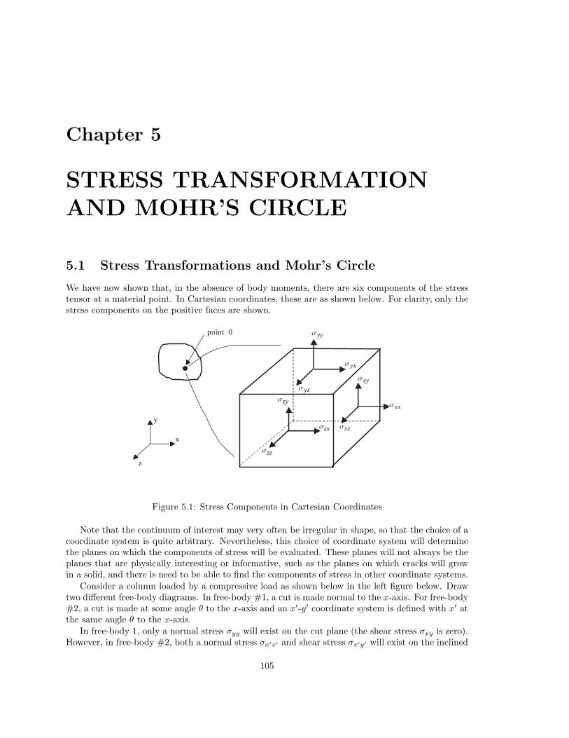
We have now shown that, in the absence of body moments, there are six components of the stresstensor at a material point. In Cartesian coordinates, these are as shown below. For clarity, only thestress components on the positive faces are shown.
x
z
y
point 0
zyσ
zxσ
zzσ
yyσ
yxσ
yzσ xyσ
xxσ
xzσ
Figure 5.1: Stress Components in Cartesian Coordinates
Note that the continuum of interest may very often be irregular in shape, so that the choice of acoordinate system is quite arbitrary. Nevertheless, this choice of coordinate system will determinethe planes on which the components of stress will be evaluated. These planes will not always be theplanes that are physically interesting or informative, such as the planes on which cracks will growin a solid, and there is need to be able to find the components of stress in other coordinate systems.
Consider a column loaded by a compressive load as shown below in the left figure below. Drawtwo different free-body diagrams. In free-body #1, a cut is made normal to the x-axis. For free-body#2, a cut is made at some angle θ to the x-axis and an x′-y′ coordinate system is defined with x′ atthe same angle θ to the x-axis.
In free-body 1, only a normal stress σyy will exist on the cut plane (the shear stress σxy is zero).However, in free-body #2, both a normal stress σx′x′ and shear stress σx′y′ will exist on the inclined
105

106 CHAPTER 5. STRESS TRANSFORMATION AND MOHR’S CIRCLE
p p
column withcompressive load free-body #1 free-body #2
p
θσx′x′
σx′y′x
′
y′
x
y
σyy
Figure 5.2: Column Loaded in Compression
plane (the traction vector on the inclined surface must have two components so that the resultantforce equilibrates the applied load). Consequently, it is important to be able to define the stress onany plane with any orientation relative to the x-axis. In this case, no shear stress exists in the x-ycoordinate system, but does exist in the x′-y′ coordinate system. In free-body #2, σx′x′ and σx′y′
must satisfy conservation of linear momentum such that the sum of the horizontal components ofthe forces due to the stresses are zero, while the sum of the vertical components must equal thevertical force due to the applied traction on the column.
Thus, it is desirable to develop a method for determining the stresses on arbitrary planes at anypoint once σxx, σyy, σzz, σyz, σxz, and σxy have been determined. The process of finding thesestresses in a coordinate system like x′-y′, which is rotated by some angle θ relative to the x-axis, iscalled stress transformation.
In this text, we will consider only states of stress in which shear stresses are non-zero in at mostone plane. This state of stress is termed generalized plane stress. An example of generalizedplane stress in the x-y plane is shown below. Note that no shear stresses exist in the y-z or x-zplanes for this example.
x
z
y
yyσ
yyσ
zzσ
zzσ
xxσ xxσ
xyσ
xyσ
yxσ
yxσ
Figure 5.3: Generalized Plane Stress in x-y Plane
Principal stress is defined as the normal stress that exists on a plane (at some angle θ) where
5.1. STRESS TRANSFORMATIONS AND MOHR’S CIRCLE 107
all shear stresses are equal to zero. In Figure 5.3 above, σzz is a principal stress since no shearstresses are shown on the z face (the face with unit outward normal k). Since the coordinate systemis arbitrary, note that if a state of generalized plane stress exists at a point, the coordinate systemcan always be rotated such that the x′-y′ stress state is as shown below in Figure 5.4
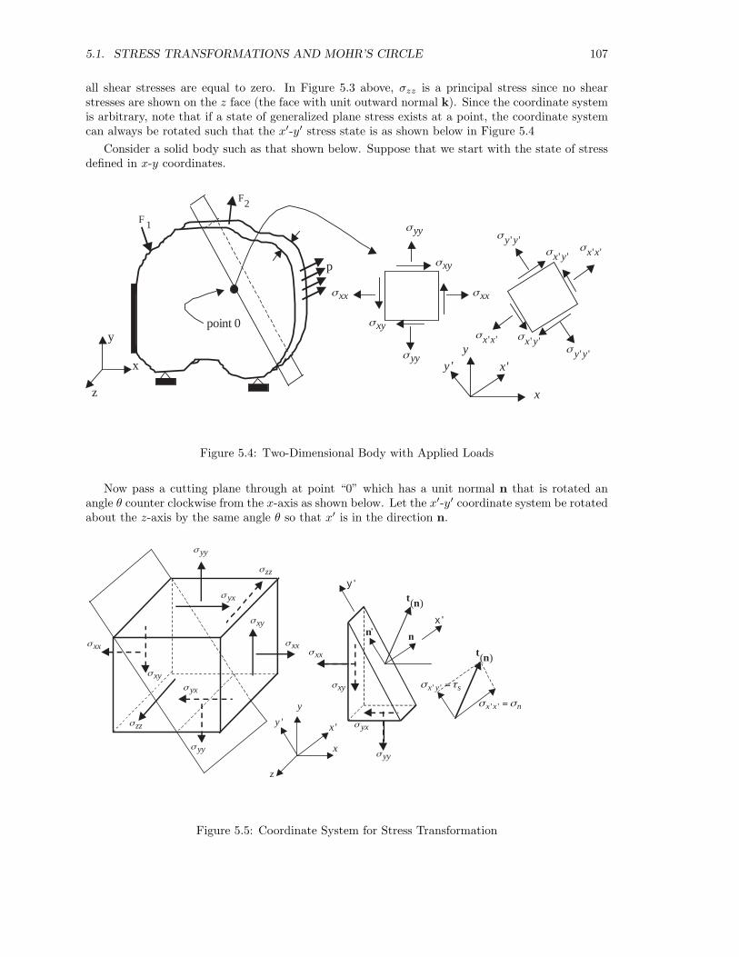
Consider a solid body such as that shown below. Suppose that we start with the state of stressdefined in x-y coordinates.
p
F 1
F2
x
y
z
point 0
yyσ
yyσ
xxσ xxσ
xyσ
xyσ
' 'y yσ
' 'y yσ
' 'x xσ
' 'x xσ
' 'x yσ
' 'x yσ y
'y 'x
x
Figure 5.4: Two-Dimensional Body with Applied Loads
Now pass a cutting plane through at point “0” which has a unit normal n that is rotated anangle θ counter clockwise from the x-axis as shown below. Let the x′-y′ coordinate system be rotatedabout the z-axis by the same angle θ so that x′ is in the direction n.
'y
y
'x
x
z
yyσ
yyσ
zzσ
zzσ
yxσ
yxσ
xyσ
xyσ
xxσ xxσ n'
n
( )t n
xxσ
xyσ
yxσ
yyσ
x '
y '
( )t n
' 'x x nσ σ =
' 'x y sσ τ =
Figure 5.5: Coordinate System for Stress Transformation
108 CHAPTER 5. STRESS TRANSFORMATION AND MOHR’S CIRCLE
For the above case the unit outer normal vector n, is given by
n = cos θi + sin θj (5.1)
Therefore, application of Cauchy’s formula (t(n) = n ·σ) results in the following components for t(n)
(the stress tensor is assumed to be symmetric and therefore σyx = σxy):
t(n)x= σxx cos θ + σyx sin θ
t(n)y= σxy cos θ + σyy sin θ (5.2)
t(n)z= 0
However, these components are of no particular physical interest since they are neither normal norparallel to the plane defined by n. The components of t(n) that are normal and parallel to the planedefined by n can be easily obtained through vector calculus. Note that the unit normal n and thex′-axis have the same direction. The component of t(n) normal to the plane is thus σx′x′ and isgiven by the dot product of t(n) with n (note: first substitute σyx = σxy in t(n)x
):
σx′x′ = t(n) · n = ((σxx cos θ + σxy sin θ)i + (σxy cos θ + σyy sin θ)j) · (cos θi + sin θj) (5.3)
= σxx cos2 θ + 2σxy sin θ cos θ + σyy sin2 θ
where the x′-y′ axes are rotated counterclockwise from the x-axes by the angle θ.Since the x′ axis is in the direction of n, σx′x′ (stress normal to plane with unit normal n) is
often denoted as σn. Equations 5.2 and 5.3 can also be combined by writing t(n) = n · σ andσn = σx′x′ = t(n) · n so that we have the following vector and matrix result:
σn = σx′x′ = n · σ · n =(1×2)
[n](2×2)
[σ](2×1)
[n] (5.4)
In order to obtain the component of t(n) parallel to the plane defined by n, it is first convenient todefine the unit normal in the y′ direction, denoted n′, as follows:
n′ = k × n = − sin θi + cos θj (5.5)
The projection of t(n) on the plane n is found by taking the dot product of t(n) with n′, thus yieldingthe shear stress component σx′y′ ,
σx′y′ = t(n) · n′ =⇒ (5.6)
σx′y′ = −(σxx − σyy) sin θ cos θ + σxy(cos2 θ − sin2 θ)
In the same manner, σy′y′ and σy′x′ can be determined (note: this step is not necessary):
σy′y′ = t(n′) · n′ =⇒σy′y′ = [−(−σxx sin θ + σxy cos θ) sin θ + (−σyx sin θ + σyy cos θ) cos θ]σy′x′ = t(n′) · n =⇒σy′x′ = [(−σxx sin θ + σxy cos θ) cos θ + (−σyx sin θ + σyy cos θ) sin θ]
Equations 5.3 and 5.6 can now be used to obtain the normal stress, σx′x′ , and shear stress, σx′y′ , ona plane defined by the angle θ (measured CCW from x-axis), given σxx, σyy and σxy:
Stress Transformation from x-y to x′-y′ Coordinates
σx′x′ = σxx cos2 θ + 2σxy sin θ cos θ + σyy sin2 θ (5.7)σx′y′ = −(σxx − σyy) sin θ cos θ + σxy(cos2 θ − sin2 θ)
5.1. STRESS TRANSFORMATIONS AND MOHR’S CIRCLE 109
Although the above equations are sufficient to perform stress transformations, they are not veryconvenient. This is due to the fact that we are often interested in finding the planes defined by θ onwhich σx′x′ and σx′y′ attain their maxima because failure is often initiated on these planes due tothe stresses on these planes. Mathematically, an equation for the plane of maximum (or minimum)stress can be obtained from calculus by applying the following:
dσx′x′
dθ= −(σxx − σyy) sin 2θ + 2σxy cos 2θ = 0 (5.8)
dσx′y′
dθ= −2σxy sin 2θ − (σxx − σyy) cos 2θ = 0
Equations (5.8) can be solved for θ that maximizes/minimizes σx′x′ and σx′y′ . Note that one obtainsone value from each equation, i.e., θ defining the plane of maximum normal stress σx′x′ (call it θP ),and a second θ for the maximum shear stress (call it θS). It can be shown that θS = θP ± π
4 .Thus, the plane of maximum shear stress is always ±45◦ from the plane of maximum normal stress.These corresponding two values of θ may then be substituted into (5.7) to obtain the maximum andminimum values of σx′x′ and σx′y′ . Because equations (5.8) are transcendental, closed form solutionsfor θ do not exist; however they can be solved numerically or graphically.
It is important to note that numerical evaluations using equations (5.7) and (5.8) must be donewith the angle θ in radians, not degrees. Furthermore, θ is positive counterclockwise from the x-axis(normal right-hand rule for an x-y coordinate system).
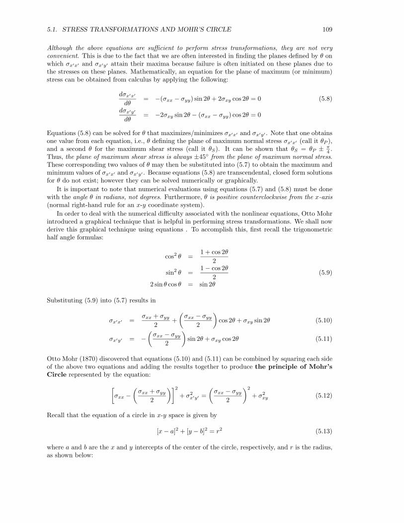
In order to deal with the numerical difficulty associated with the nonlinear equations, Otto Mohrintroduced a graphical technique that is helpful in performing stress transformations. We shall nowderive this graphical technique using equations . To accomplish this, first recall the trigonometrichalf angle formulas:
cos2 θ =1 + cos 2θ
2
sin2 θ =1 − cos 2θ
2(5.9)
2 sin θ cos θ = sin 2θ
Substituting (5.9) into (5.7) results in
σx′x′ =σxx + σyy
2+
(σxx − σyy
2
)cos 2θ + σxy sin 2θ (5.10)
σx′y′ = −(
σxx − σyy
2
)sin 2θ + σxy cos 2θ (5.11)
Otto Mohr (1870) discovered that equations (5.10) and (5.11) can be combined by squaring each sideof the above two equations and adding the results together to produce the principle of Mohr’sCircle represented by the equation:
[σxx −
(σxx + σyy
2
)]2
+ σ2x′y′ =
(σxx − σyy
2
)2
+ σ2xy (5.12)
Recall that the equation of a circle in x-y space is given by
[x − a]2 + [y − b]2 = r2 (5.13)
where a and b are the x and y intercepts of the center of the circle, respectively, and r is the radius,as shown below:
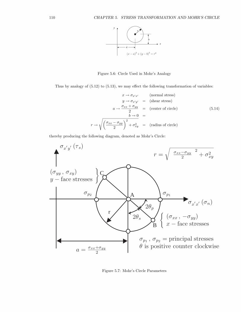
110 CHAPTER 5. STRESS TRANSFORMATION AND MOHR’S CIRCLE
y
b
ax
r
(x − a)2 + (y − b)2 = r2
Figure 5.6: Circle Used in Mohr’s Analogy
Thus by analogy of (5.12) to (5.13), we may effect the following transformation of variables:
x → σx′x′ (normal stress)y → σx′y′ = (shear stress)
a → σxx + σyy
2= (center of circle) (5.14)
b → 0 =
r →
√(σxx − σyy
2
)2
+ σ2xy = (radius of circle)
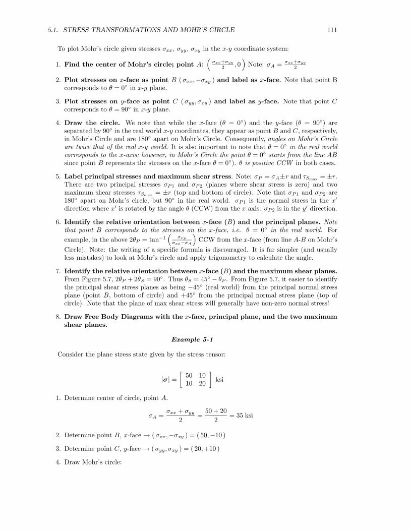
thereby producing the following diagram, denoted as Mohr’s Circle:
r
B
C
Aσx′x′ (σn)
σx′y′ (τ s)
2θp
2θs
σp1σp2
σp1 , σp2 = principal stressesθ is positive counter clockwise
r =
√ σxx−σyy
2
2+ σ2
xy
a = σxx+σyy
2
{(σxx , −σyy)x − face stresses
(σyy , σxy)y − face stresses
}
Figure 5.7: Mohr’s Circle Parameters
5.1. STRESS TRANSFORMATIONS AND MOHR’S CIRCLE 111
To plot Mohr’s circle given stresses σxx, σyy, σxy in the x-y coordinate system:
1. Find the center of Mohr’s circle; point A:(
σxx+σyy
2 , 0)
Note: σA = σxx+σyy
2
2. Plot stresses on x-face as point B (σxx,−σxy ) and label as x-face. Note that point Bcorresponds to θ = 0◦ in x-y plane.
3. Plot stresses on y-face as point C (σyy, σxy ) and label as y-face. Note that point Ccorresponds to θ = 90◦ in x-y plane.
4. Draw the circle. We note that while the x-face (θ = 0◦) and the y-face (θ = 90◦) areseparated by 90◦ in the real world x-y coordinates, they appear as point B and C, respectively,in Mohr’s Circle and are 180◦ apart on Mohr’s Circle. Consequently, angles on Mohr’s Circleare twice that of the real x-y world. It is also important to note that θ = 0◦ in the real worldcorresponds to the x-axis; however, in Mohr’s Circle the point θ = 0◦ starts from the line ABsince point B represents the stresses on the x-face θ = 0◦). θ is positive CCW in both cases.
5. Label principal stresses and maximum shear stress. Note: σP = σA±r and τSmax = ±r.There are two principal stresses σP1 and σP2 (planes where shear stress is zero) and twomaximum shear stresses τSmax = ±r (top and bottom of circle). Note that σP1 and σP2 are180◦ apart on Mohr’s circle, but 90◦ in the real world. σP1 is the normal stress in the x′
direction where x′ is rotated by the angle θ (CCW) from the x-axis. σP2 is in the y′ direction.
6. Identify the relative orientation between x-face (B) and the principal planes. Notethat point B corresponds to the stresses on the x-face, i.e. θ = 0◦ in the real world. Forexample, in the above 2θP = tan−1
(σxy
σxx−σA
)CCW from the x-face (from line A-B on Mohr’s
Circle). Note: the writing of a specific formula is discouraged. It is far simpler (and usuallyless mistakes) to look at Mohr’s circle and apply trigonometry to calculate the angle.
7. Identify the relative orientation between x-face (B) and the maximum shear planes.From Figure 5.7, 2θP + 2θS = 90◦. Thus θS = 45◦ − θP . From Figure 5.7, it easier to identifythe principal shear stress planes as being −45◦ (real world) from the principal normal stressplane (point B, bottom of circle) and +45◦ from the principal normal stress plane (top ofcircle). Note that the plane of max shear stress will generally have non-zero normal stress!
8. Draw Free Body Diagrams with the x-face, principal plane, and the two maximumshear planes.
Example 5-1
Consider the plane stress state given by the stress tensor:
[σ] =[
50 1010 20
]ksi
1. Determine center of circle, point A.
σA =σxx + σyy
2=
50 + 202
= 35 ksi
2. Determine point B, x-face → ( σxx,−σxy ) = ( 50,−10 )
3. Determine point C, y-face → ( σyy, σxy ) = ( 20,+10 )
4. Draw Mohr’s circle:
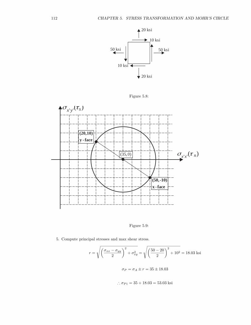
112 CHAPTER 5. STRESS TRANSFORMATION AND MOHR’S CIRCLE
50 ksi
20 ksi
10 ksi
10 ksi
20 ksi
50 ksi
Figure 5.8:
' '( )sx yσ τ
' '( )nx xσ τ
(50,-10)
x - face
(20,10)
y - face
(35,0)
Figure 5.9:
5. Compute principal stresses and max shear stress.
r =
√(σxx − σyy
2
)2
+ σ2xy =
√(50 − 20
2
)2
+ 102 = 18.03 ksi
σP = σA ± r = 35 ± 18.03
∴ σP1 = 35 + 18.03 = 53.03 ksi
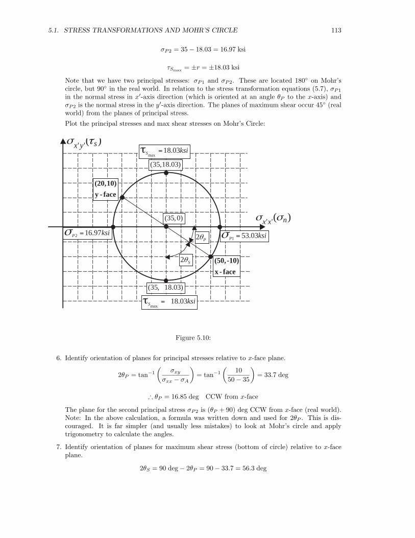
5.1. STRESS TRANSFORMATIONS AND MOHR’S CIRCLE 113
σP2 = 35 − 18.03 = 16.97 ksi
τSmax = ±r = ±18.03 ksi
Note that we have two principal stresses: σP1 and σP2. These are located 180◦ on Mohr’scircle, but 90◦ in the real world. In relation to the stress transformation equations (5.7), σP1
in the normal stress in x′-axis direction (which is oriented at an angle θP to the x-axis) andσP2 is the normal stress in the y′-axis direction. The planes of maximum shear occur 45◦ (realworld) from the planes of principal stress.
Plot the principal stresses and max shear stresses on Mohr’s Circle:
' '( )sx yσ τ
' '( )nx xσ σ
(50,-10)
x - face
(20,10)
y - face
1 53.03P ksiσ =2 16.97P ksiσ =
max18.03S ksi=τ
max18.03S ksi= τ
2 Pθ
2 Sθ
(35,0)
(35,18.03)
(35, 18.03)
Figure 5.10:
6. Identify orientation of planes for principal stresses relative to x-face plane.
2θP = tan−1
(σxy
σxx − σA
)= tan−1
(10
50 − 35
)= 33.7 deg
∴ θP = 16.85 deg CCW from x-face
The plane for the second principal stress σP2 is (θP + 90) deg CCW from x-face (real world).Note: In the above calculation, a formula was written down and used for 2θP . This is dis-couraged. It is far simpler (and usually less mistakes) to look at Mohr’s circle and applytrigonometry to calculate the angles.
7. Identify orientation of planes for maximum shear stress (bottom of circle) relative to x-faceplane.
2θS = 90 deg − 2θP = 90 − 33.7 = 56.3 deg
114 CHAPTER 5. STRESS TRANSFORMATION AND MOHR’S CIRCLE
∴ θS = 28.15 deg CW from the x-face
OR, plane of max shear stress (bottom of circle) is 45◦ CW in the real world from the principalstress plane with σP1.
Note: |σP | + |σS | = 45 deg (always!)
Note that the plane of max shear stress will generally have non-zero normal stress! In thiscase, the plane of max shear stress has a normal stress σn = 35 ksi.
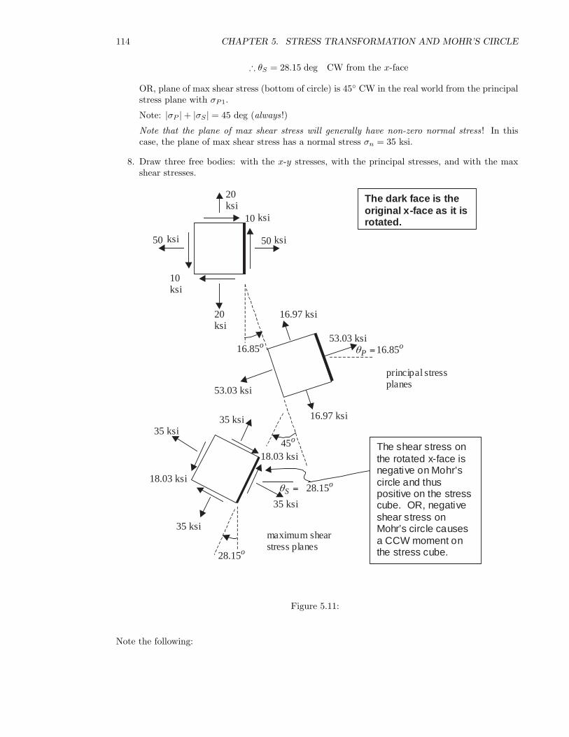
8. Draw three free bodies: with the x-y stresses, with the principal stresses, and with the maxshear stresses.
50
20ksi
10ksi
10
20ksi
50 ksi
53.03 ksi
53.03 ksi
16.97 ksi
16.97 ksi
45
35 ksi
35 ksi35 ksi
35 ksi
18.03 ksi
18.03 ksi
principal stressplanes
maximum shearstress planes
The dark face is theoriginal x-face as it isrotated.
The shear stress onthe rotated x-face isnegative on Mohr’scircle and thuspositive on the stresscube. OR, negativeshear stress onMohr’s circle causesa CCW moment onthe stress cube.
16.85oPθ =
28.15oSθ =
ksi
ksi
16.85o
28.15o
o
Figure 5.11:
Note the following:

5.1. STRESS TRANSFORMATIONS AND MOHR’S CIRCLE 115
• To obtain the orientation for principal stresses, the x-face has been rotated 16.85 deg CCW inthe real world (33.7 deg on Mohr’s circle).
• To obtain the orientation for maximum shear stresses, the x-face has been rotated 28.15 degCW in the real world (56.3 deg on Mohr’s circle), OR, equivalently a rotation of 45 deg CWin the real world from the principal stress plane.
Example 5-2
Consider the same plane stress state given in Example 5-1:
50 ksi
20 ksi
10 ksi
10 ksi
20 ksi
50 ksi
Figure 5.12:
[σ] =[
50 1010 20
]ksi
Values of principal stress and maximum shear stress obtain in Example 5-1 by Mohr’s circle mustbe identical to what would be obtained by using the stress transformation equations (5.7). This istrue because Mohr’s circle is simply a graphical representation of equations (5.7). Use the stresstransformations to determine the normal stress and shear stress for values of θ = 16.85◦, 106.85◦,−28.15◦ and verify that they correspond to the principal stress and maximum shear stress valuesobtained in Example 5-1.
For θ = 16.85◦ (same as 33.7◦ on Mohr’s circle from x-face, should equal σP1)
σx′x′ = σxx cos2 θ + 2σxy sin θ cos θ + σyy sin2 θ
= (50 ksi) cos2 16.85◦ + 2(10 ksi) sin 16.85◦ cos 16.85◦ + (20 ksi) sin2 16.85◦ = 53.03 ksiσx′y′ = −(σxx − σyy) sin θ cos θ + σxy(cos2 θ − sin2 θ)
= −(50 ksi − 20 ksi) sin 16.85◦ cos 16.85◦ + 10 ksi(cos2 16.85◦ − sin2 16.85◦) = 0 ksi
For θ = 106.85◦ (same as 213.7◦ on Mohr’s circle from x-face, should equal σP2)
σx′x′ = σxx cos2 θ + 2σxy sin θ cos θ + σyy sin2 θ
= (50 ksi) cos2 106.85◦ + 2(10 ksi) sin 106.85◦ cos 106.85◦ + (20 ksi) sin2 106.85◦ = 16.97 ksiσx′y′ = −(σxx − σyy) sin θ cos θ + σxy(cos2 θ − sin2 θ)
= −(50 ksi − 20 ksi) sin 106.85◦ cos 106.85◦ + 10 ksi(cos2 106.85◦ − sin2 106.85◦) = 0 ksi
For θ = −28.15◦ (same as −56.3◦ on Mohr’s circle from x-face, should equal τmax bottom of circle)
σx′x′ = (50 ksi) cos2(−28.15◦) + 2(10 ksi) sin(−28.15◦) cos(−28.15◦) + (20 ksi) sin2(−28.15◦) = 35 ksiσx′y′ = −(50 ksi − 20 ksi) sin(−28.15◦) cos(−28.15◦) + 10 ksi(cos2(−28.15◦) − sin2(−28.15◦)) = 18.03 ksi
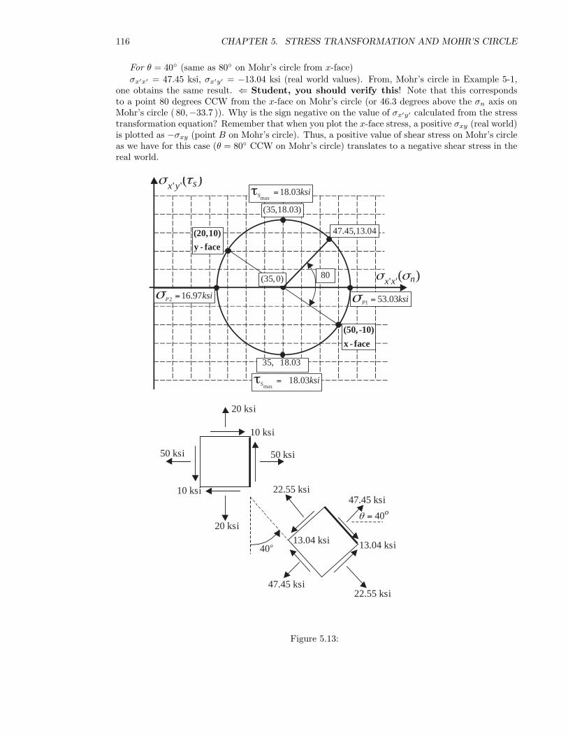
116 CHAPTER 5. STRESS TRANSFORMATION AND MOHR’S CIRCLE
For θ = 40◦ (same as 80◦ on Mohr’s circle from x-face)σx′x′ = 47.45 ksi, σx′y′ = −13.04 ksi (real world values). From, Mohr’s circle in Example 5-1,
one obtains the same result. ⇐ Student, you should verify this! Note that this correspondsto a point 80 degrees CCW from the x-face on Mohr’s circle (or 46.3 degrees above the σn axis onMohr’s circle ( 80,−33.7 )). Why is the sign negative on the value of σx′y′ calculated from the stresstransformation equation? Remember that when you plot the x-face stress, a positive σxy (real world)is plotted as −σxy (point B on Mohr’s circle). Thus, a positive value of shear stress on Mohr’s circleas we have for this case (θ = 80◦ CCW on Mohr’s circle) translates to a negative shear stress in thereal world.
50 ksi
20 ksi
10 ksi
10 ksi
20 ksi
50 ksi
13.04 ksi
47.45 ksi
40o
47.45 ksi22.55 ksi
22.55 ksi
13.04 ksi13.04 ksi
40o θ =
' '( )sx yσ τ
' '( )nx xσ σ
(50,-10)
x - face
(20,10)
y - face
1 53.03P ksiσ =2 16.97P ksiσ =
max18.03S ksi=τ
max18.03S ksi= τ
(35,0)
(35,18.03)
80
47.45,13.04
35, 18.03
Figure 5.13:
5.1. STRESS TRANSFORMATIONS AND MOHR’S CIRCLE 117
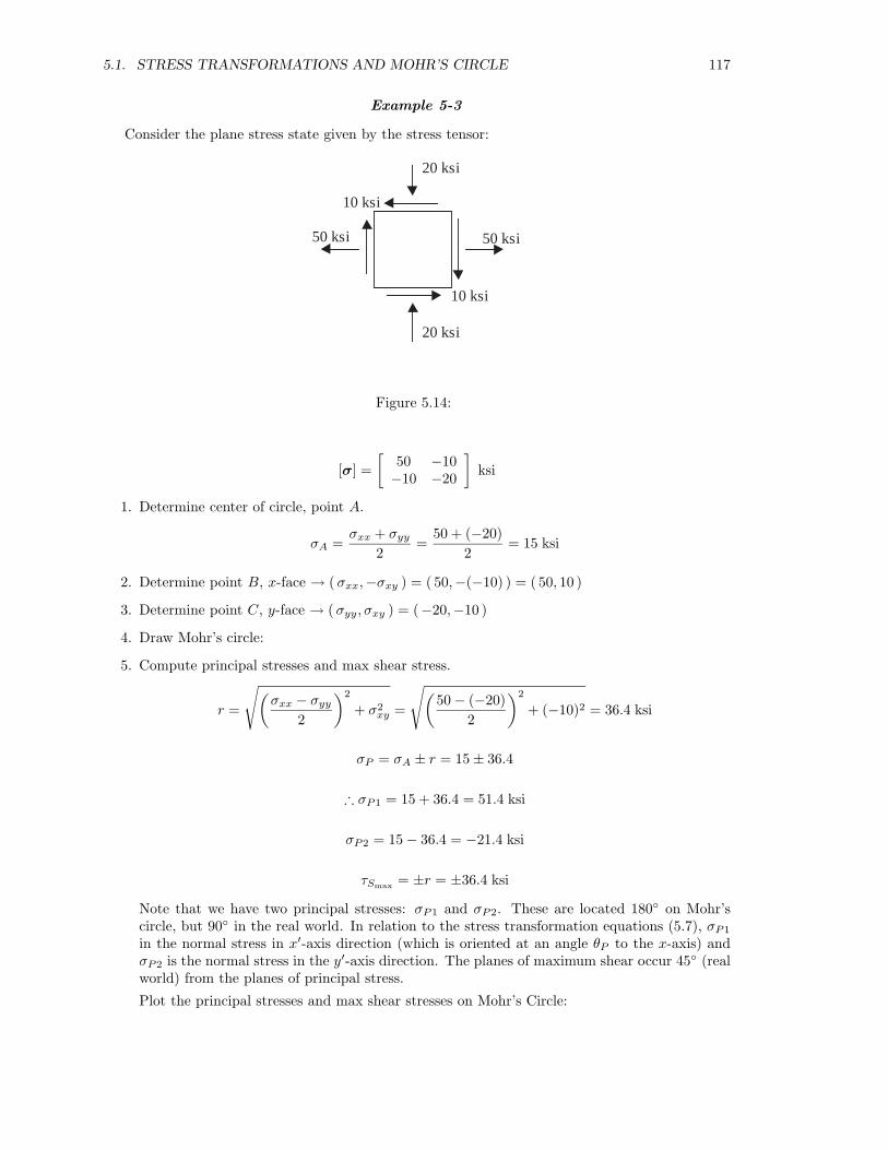
Example 5-3
Consider the plane stress state given by the stress tensor:
50 ksi
20 ksi
10 ksi
10 ksi
20 ksi
50 ksi
Figure 5.14:
[σ] =[
50 −10−10 −20
]ksi
1. Determine center of circle, point A.
σA =σxx + σyy
2=
50 + (−20)2
= 15 ksi
2. Determine point B, x-face → ( σxx,−σxy ) = ( 50,−(−10) ) = ( 50, 10 )
3. Determine point C, y-face → ( σyy, σxy ) = (−20,−10 )
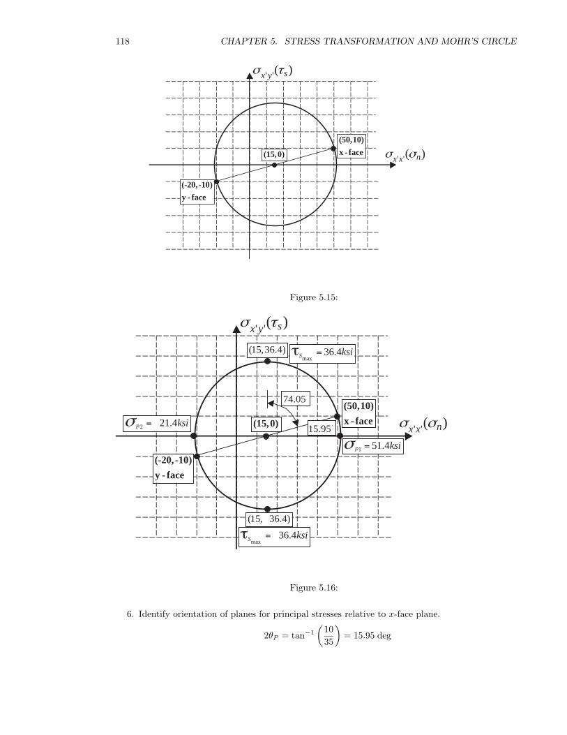
4. Draw Mohr’s circle:
5. Compute principal stresses and max shear stress.
r =
√(σxx − σyy
2
)2
+ σ2xy =
√(50 − (−20)
2
)2
+ (−10)2 = 36.4 ksi
σP = σA ± r = 15 ± 36.4
∴ σP1 = 15 + 36.4 = 51.4 ksi
σP2 = 15 − 36.4 = −21.4 ksi
τSmax = ±r = ±36.4 ksi
Note that we have two principal stresses: σP1 and σP2. These are located 180◦ on Mohr’scircle, but 90◦ in the real world. In relation to the stress transformation equations (5.7), σP1
in the normal stress in x′-axis direction (which is oriented at an angle θP to the x-axis) andσP2 is the normal stress in the y′-axis direction. The planes of maximum shear occur 45◦ (realworld) from the planes of principal stress.
Plot the principal stresses and max shear stresses on Mohr’s Circle:
118 CHAPTER 5. STRESS TRANSFORMATION AND MOHR’S CIRCLE
' '( )sx yσ τ
' '( )nx xσ σ (50,10)
x - face
(-20, -10)
y - face
(15,0)
Figure 5.15:
' '( )sx yσ τ
' '( )nx xσ σ (50,10)
x - face
(-20, -10)
y - face
(15,0)
1 51.4P ksiσ =
2 21.4P ksiσ =
(15,36.4)
(15, 36.4)
max36.4S ksi= τ
max36.4S ksi=τ
15.95
74.05
Figure 5.16:
6. Identify orientation of planes for principal stresses relative to x-face plane.
2θP = tan−1
(1035
)= 15.95 deg
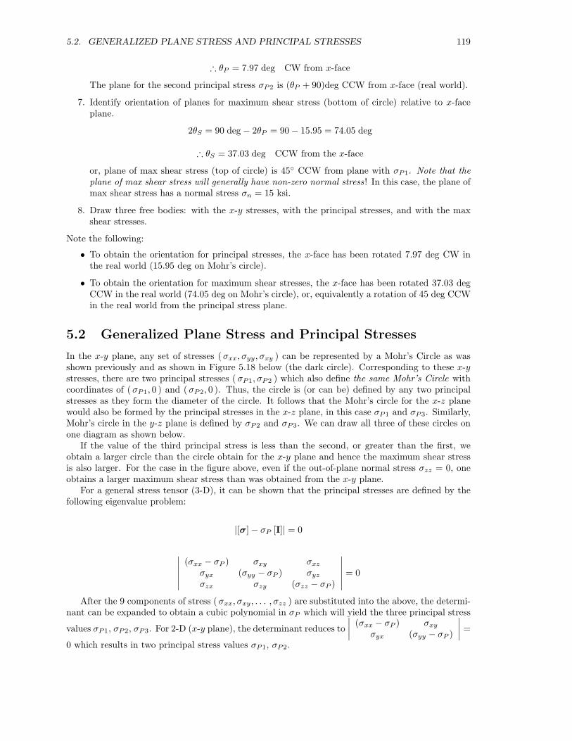
5.2. GENERALIZED PLANE STRESS AND PRINCIPAL STRESSES 119
∴ θP = 7.97 deg CW from x-face
The plane for the second principal stress σP2 is (θP + 90)deg CCW from x-face (real world).
7. Identify orientation of planes for maximum shear stress (bottom of circle) relative to x-faceplane.
2θS = 90 deg − 2θP = 90 − 15.95 = 74.05 deg
∴ θS = 37.03 deg CCW from the x-face
or, plane of max shear stress (top of circle) is 45◦ CCW from plane with σP1. Note that theplane of max shear stress will generally have non-zero normal stress! In this case, the plane ofmax shear stress has a normal stress σn = 15 ksi.
8. Draw three free bodies: with the x-y stresses, with the principal stresses, and with the maxshear stresses.
Note the following:
• To obtain the orientation for principal stresses, the x-face has been rotated 7.97 deg CW inthe real world (15.95 deg on Mohr’s circle).
• To obtain the orientation for maximum shear stresses, the x-face has been rotated 37.03 degCCW in the real world (74.05 deg on Mohr’s circle), or, equivalently a rotation of 45 deg CCWin the real world from the principal stress plane.
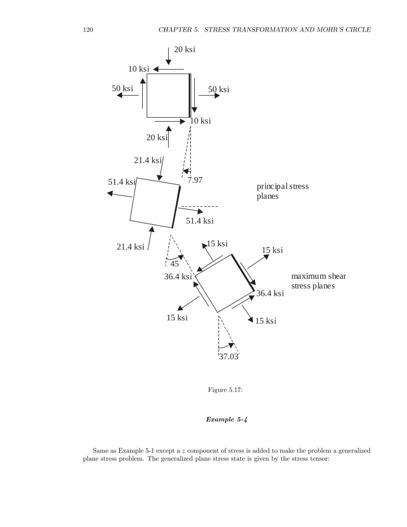
5.2 Generalized Plane Stress and Principal Stresses
In the x-y plane, any set of stresses ( σxx, σyy, σxy ) can be represented by a Mohr’s Circle as wasshown previously and as shown in Figure 5.18 below (the dark circle). Corresponding to these x-ystresses, there are two principal stresses ( σP1, σP2 ) which also define the same Mohr’s Circle withcoordinates of (σP1, 0 ) and (σP2, 0 ). Thus, the circle is (or can be) defined by any two principalstresses as they form the diameter of the circle. It follows that the Mohr’s circle for the x-z planewould also be formed by the principal stresses in the x-z plane, in this case σP1 and σP3. Similarly,Mohr’s circle in the y-z plane is defined by σP2 and σP3. We can draw all three of these circles onone diagram as shown below.
If the value of the third principal stress is less than the second, or greater than the first, weobtain a larger circle than the circle obtain for the x-y plane and hence the maximum shear stressis also larger. For the case in the figure above, even if the out-of-plane normal stress σzz = 0, oneobtains a larger maximum shear stress than was obtained from the x-y plane.
For a general stress tensor (3-D), it can be shown that the principal stresses are defined by thefollowing eigenvalue problem:
|[σ] − σP [I]| = 0
∣∣∣∣∣∣(σxx − σP ) σxy σxz
σyx (σyy − σP ) σyz
σzx σzy (σzz − σP )
∣∣∣∣∣∣ = 0
After the 9 components of stress ( σxx, σxy, . . . , σzz ) are substituted into the above, the determi-nant can be expanded to obtain a cubic polynomial in σP which will yield the three principal stress
values σP1, σP2, σP3. For 2-D (x-y plane), the determinant reduces to∣∣∣∣ (σxx − σP ) σxy
σyx (σyy − σP )
∣∣∣∣ =
0 which results in two principal stress values σP1, σP2.
120 CHAPTER 5. STRESS TRANSFORMATION AND MOHR’S CIRCLE
50 ksi
20 ksi
10 ksi
10 ksi
20 ksi
50 ksi
15 ksi
45
36.4 ksi
principal stressplanes
maximum shearstress planes
7.97
15 ksi
15 ksi 15 ksi
36.4 ksi
37.03
21.4 ksi
51.4 ksi
51.4 ksi
21.4 ksi
Figure 5.17:
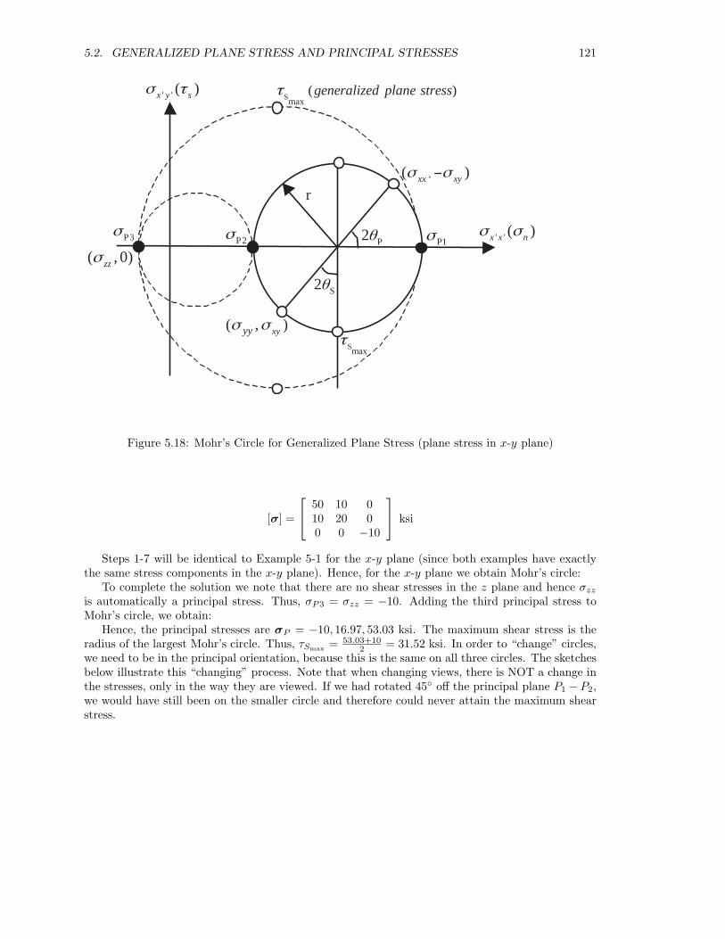
Example 5-4
Same as Example 5-1 except a z component of stress is added to make the problem a generalizedplane stress problem. The generalized plane stress state is given by the stress tensor:
5.2. GENERALIZED PLANE STRESS AND PRINCIPAL STRESSES 121
r
' ' ( )x y sσ τ
,( )xx xyσ σ −
P3σ P2σ
P2θ P1σ ' ' ( )x x nσ σ
S2θ
( , 0)zzσ
Smaxτ
Smax( )generalized plane stressτ
( , )xyyyσ σ
Figure 5.18: Mohr’s Circle for Generalized Plane Stress (plane stress in x-y plane)
[σ] =
50 10 0
10 20 00 0 −10
ksi
Steps 1-7 will be identical to Example 5-1 for the x-y plane (since both examples have exactlythe same stress components in the x-y plane). Hence, for the x-y plane we obtain Mohr’s circle:
To complete the solution we note that there are no shear stresses in the z plane and hence σzz
is automatically a principal stress. Thus, σP3 = σzz = −10. Adding the third principal stress toMohr’s circle, we obtain:
Hence, the principal stresses are σP = −10, 16.97, 53.03 ksi. The maximum shear stress is theradius of the largest Mohr’s circle. Thus, τSmax = 53.03+10
2 = 31.52 ksi. In order to “change” circles,we need to be in the principal orientation, because this is the same on all three circles. The sketchesbelow illustrate this “changing” process. Note that when changing views, there is NOT a change inthe stresses, only in the way they are viewed. If we had rotated 45◦ off the principal plane P1 − P2,we would have still been on the smaller circle and therefore could never attain the maximum shearstress.
122 CHAPTER 5. STRESS TRANSFORMATION AND MOHR’S CIRCLE
' '( )sx yσ τ
' '( )nx xσ σ
(50, -10)
x - face
(20,10)
y - face
1 53.03P ksiσ =2 16.97P ksiσ =
max18.03S ksi=τ
max18.03S ksi= τ
2 Sθ
(35,0)
(35,18.03)
(35, 18.03)
16.85
Figure 5.19:
' '( )sx yσ τ
' '( )nx xσ σ
(50,-10)
x- face
(20,10)
y -face
1 53.03P ksiσ =2 16.97P ksiσ =
2 Sθ
(35,0)
(35,18.03)
(35, 18.03)
16.853 10P ksiσ =
max31.52S ksi=τ
max31.52S ksi= τ
Figure 5.20:
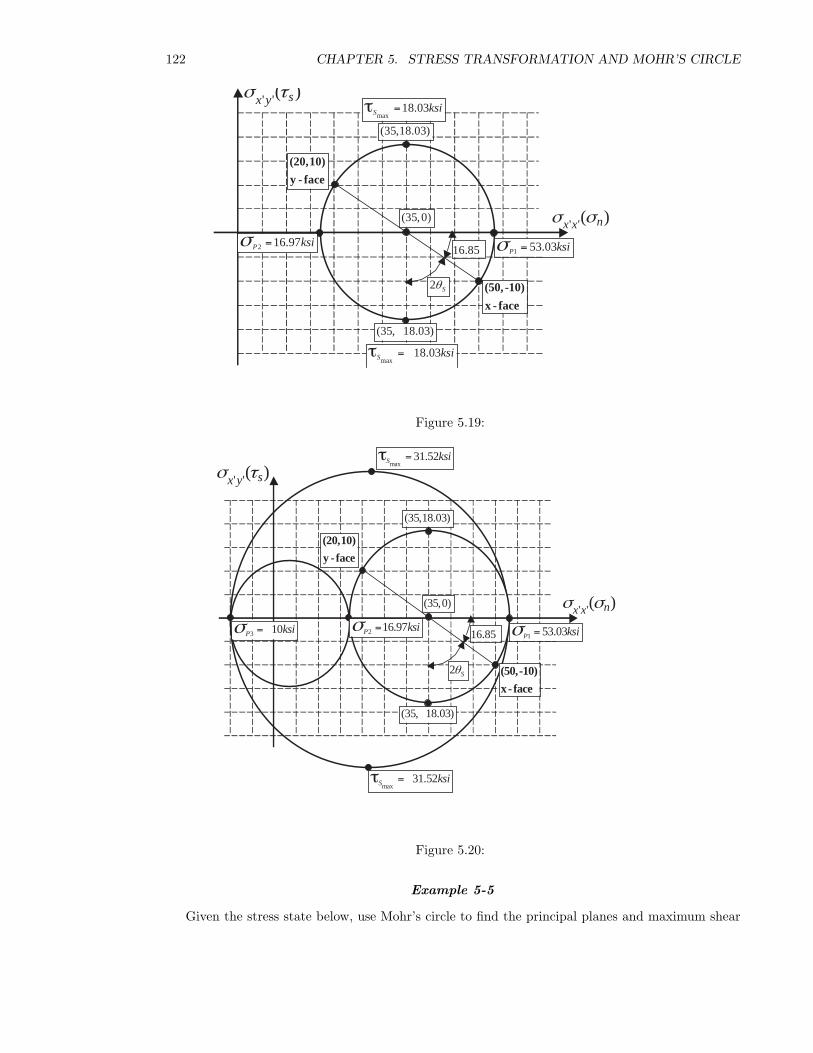
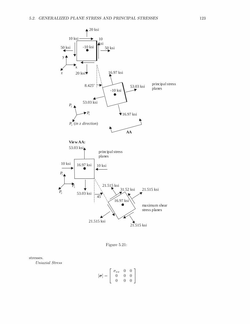
Example 5-5
Given the stress state below, use Mohr’s circle to find the principal planes and maximum shear
5.2. GENERALIZED PLANE STRESS AND PRINCIPAL STRESSES 123
50 ksi
20 ksi
10ksi
10 ksi
20 ksi
50 ksi
45
31.52 ksi
principal stressplanes
maximum shearstress planes
21.515 ksi
16.97 ksi
53.03 ksi
53.03 ksi
16.97 ksi
-10 ksi
8.425o
-10 ksi
AA
Vie w AA:
16.97 ksi
53.03 ksi
53.03 ksi
10 ksi10 ksi
16.97 ksi
21.515 ksi21.515 ksi
21.515 ksi
principal stressplanes
z
x
y
1P
2P
1P
2P3P
3 ( )P in z direction
Figure 5.21:
stresses.Uniaxial Stress
[σ] =
σxx 0 0
0 0 00 0 0
124 CHAPTER 5. STRESS TRANSFORMATION AND MOHR’S CIRCLE
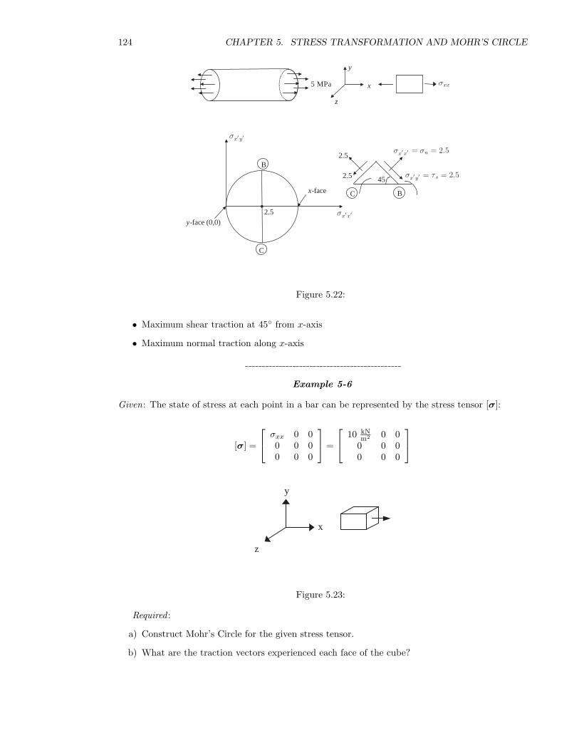
5 MPa
y
x
z
B
C
2.5
-facex
-face (0,0)y
C B
2.5
2.5 45
σx′x′
σx′y′
σx′x′ = σn = 2.5
σx′y′ = τ s = 2.5
σxx
Figure 5.22:
• Maximum shear traction at 45◦ from x-axis
• Maximum normal traction along x-axis
Example 5-6
Given: The state of stress at each point in a bar can be represented by the stress tensor [σ]:
[σ] =
σxx 0 0
0 0 00 0 0
=
10 kN
m2 0 00 0 00 0 0
x
y
z
Figure 5.23:
Required :
a) Construct Mohr’s Circle for the given stress tensor.
b) What are the traction vectors experienced each face of the cube?
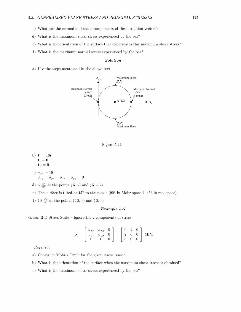
5.2. GENERALIZED PLANE STRESS AND PRINCIPAL STRESSES 125
c) What are the normal and shear components of these traction vectors?
d) What is the maximum shear stress experienced by the bar?
e) What is the orientation of the surface that experiences this maximum shear stress?
f) What is the maximum normal stress experienced by the bar?
Solution
a) Use the steps mentioned in the above text.
' 'x y
Maximum Normalx-faceB (10,0)
Maximum Shear(5,5)
A (5,0)
Maximum Normaly-face
C (0,0)
(5,-5)Maximum Shear
' 'x xσ
σ
Figure 5.24:
b) ti = 10itj = 0tk = 0
c) σxx = 10σxy = σyz = σzz = σyy = 0
d) 5 kNm2 at the points ( 5, 5 ) and ( 5,−5 )
e) The surface is tilted at 45◦ to the x-axis (90◦ in Mohr space is 45◦ in real space).
f) 10 kNm2 at the points ( 10, 0 ) and ( 0, 0 )
Example 5-7
Given: 2-D Stress State – Ignore the z components of stress.
[σ] =
σxx σxy 0
σyx σyy 00 0 0
=
6 2 0
2 6 00 0 0
MPa
Required :
a) Construct Mohr’s Circle for the given stress tensor.
b) What is the orientation of the surface when the maximum shear stress is obtained?
c) What is the maximum shear stress experienced by the bar?
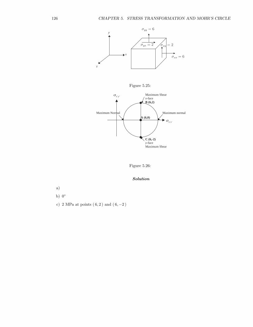
126 CHAPTER 5. STRESS TRANSFORMATION AND MOHR’S CIRCLE
x
y
z
σxx = 6
σxy = 2σyx = 2
σyy = 6
Figure 5.25:
Maximum normal
Maximum Shearx-faceB (6,2)
C (6,-2)y-faceMaximum Shear
Maximum Normal
' 'x xσ A (6,0)
' 'x yσ
Figure 5.26:
Solution
a)
b) 0◦
c) 2 MPa at points ( 6, 2 ) and ( 6,−2 )
5.2. GENERALIZED PLANE STRESS AND PRINCIPAL STRESSES 127
Deep Thought
128 CHAPTER 5. STRESS TRANSFORMATION AND MOHR’S CIRCLE
5.3 Questions
5.1 Describe in your own words the meaning of principal stress.
5.2 What is the angle between the planes of principal stress and maximum shear stress in a body?Why is it that way?
5.3 What is the main point of Mohr’s circle?
5.4 What does the term t(n) in Caucy’s formula physically represent?
5.5 When considering Mohr’s circle, explain physically the stress state defined by the point onMohr’s Circle that lies on the horizontal axis.
5.4 Problems
5.6 GIVEN : A material point is known to be in a state of generalized plane stress as given by:
[σ] =
4 −2 0
−2 −5 00 0 −3
MPa
REQUIRED : Draw all important sketches, showing planes of maximum shear as well as prin-cipal planes.
5.7 GIVEN : The stress tensor as follows:
[σ] =
3 0 0
0 19 00 0 0
ksi
REQUIRED :
(a) compute the three principal stresses and maximum shear stress;
(b) indicate the maximum shear direction.
5.8 The state of stress at a certain point of a body is given by
[σ] =
1 2 0
2 7 00 0 0
MPa
Determine on which planes:
i) principal stresses occur
ii) shearing stress is greatest.
5.9
[σ] =
σxx 0 0
0 0 00 0 0
psi
Find maximum shear and normal stresses.
5.10 (a) What is a principal plane?
5.4. PROBLEMS 129
725 psi
y
x
z
σ xx
Problem 5.9
(b) Are the following stress tensors generalized plane stress cases? Answer in yes/no.
i)
1 0 −3
0 2 0−3 0 −5
ii)
4 2 0
2 −3 10 1 2
iii)
1 0 0
0 0 −10 −1 6
iv)
−2 0 2
0 3 72 7 5
5.11 GIVEN :
[σ] =
2 0 0
0 −8 00 0 10
ksi
(a) Write out the three principal stresses and compute the maximum shear stress.
(b) What is the maximum shear direction and on what plane is it acting in?
5.12 GIVEN :
[σ] =[
−5 −5−5 5
]MPa
(a) Draw the corresponding stress cube.
(b) Construct the three Mohr’s circles for the given stress state.
(c) Compute the two principal stresses and maximum shear stress.
(d) Using the formula given below, determine the normal stress, which acts upon a surfacecorresponding to a 30◦ clockwise rotation of the x-face.
σn =(
σxx − σyy
2
)cos 2θ + σxy sin 2θ +
(σxx + σyy
2
)
5.13 GIVEN : A material in the following state of plane stress:
[σ] =
−2500 0 0
0 0 00 0 0
ksi
REQUIRED : Draw all important sketches, showing planes of maximum shear stress as well asprincipal planes.
130 CHAPTER 5. STRESS TRANSFORMATION AND MOHR’S CIRCLE
5.14 Using the following 2-D stress state at a point in a body,
[σ] =
50 0 0
0 −50 00 0 0
MPa
Find:
a) tn for n = i, n = j, and n = 12
(√3i + j
)b) If the coordinate axes were rotated 45 degrees clockwise, to x′-y′, solve for the new values
of σx′x′ , σy′y′ , σx′y′ . Use Cauchy’s Formula.
c) Construct the three Mohr’s circles for the given stress state.
5.15 The state of stress at a certain point of a body is given by
[σ] =
3 −1 4
−1 2 04 0 −2
ksi
i) Find the traction vector on the plane whose normal is in the direction i + 2j + 2k
ii) Find the traction vector on the plane whose normal is in the direction 4i − 3j + k
iii) Determine the normal and shearing components of the traction vector on the above planes.
5.16 For a stress state defined by: σxx = 10 MPa, σxy = σyx = 40 MPa, σyy = 50 MPa. Define:
a) the value of the Principal Stress
b) the maximum Shear Stress and corresponding Normal Stress
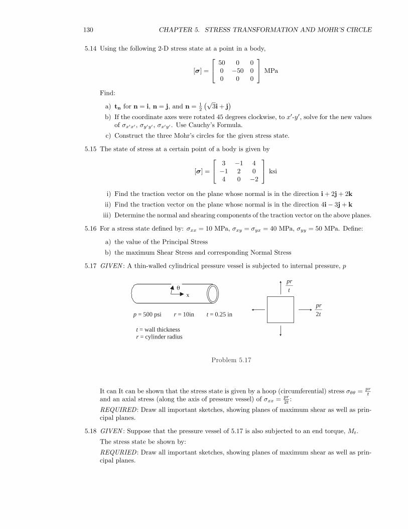
5.17 GIVEN : A thin-walled cylindrical pressure vessel is subjected to internal pressure, p
t = wall thicknessr = cylinder radius
p = 500 psi r = 10in t = 0.25 in
xθ
pr
t
pr
t2
Problem 5.17
It can It can be shown that the stress state is given by a hoop (circumferential) stress σθθ = prt
and an axial stress (along the axis of pressure vessel) of σxx = pr2t :
REQUIRED : Draw all important sketches, showing planes of maximum shear as well as prin-cipal planes.
5.18 GIVEN : Suppose that the pressure vessel of 5.17 is also subjected to an end torque, Mt.
The stress state be shown by:
REQURIED : Draw all important sketches, showing planes of maximum shear as well as prin-cipal planes.
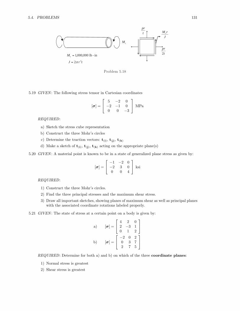
5.4. PROBLEMS 131
Mt
Mt = 1 000 000, , lb - in
pr
t
pr
t2
M r
Jt
J r t= 2 3π
Problem 5.18
5.19 GIVEN : The following stress tensor in Cartesian coordinates
[σ] =
5 −2 0
−2 −1 00 0 −3
MPa
REQUIRED :
a) Sketch the stress cube representation
b) Construct the three Mohr’s circles
c) Determine the traction vectors: t(i), t(j), t(k)
d) Make a sketch of t(i), t(j), t(k) acting on the appropriate plane(s)
5.20 GIVEN : A material point is known to be in a state of generalized plane stress as given by:
[σ] =
−1 −2 0
−2 3 00 0 4
ksi
REQUIRED :
1) Construct the three Mohr’s circles.
2) Find the three principal stresses and the maximum shear stress.
3) Draw all important sketches, showing planes of maximum shear as well as principal planeswith the associated coordinate rotations labeled properly.
5.21 GIVEN : The state of stress at a certain point on a body is given by:
a) [σ] =
4 2 0
2 −3 10 1 2
b) [σ] =
−2 0 2
0 3 72 7 5
REQUIRED : Determine for both a) and b) on which of the three coordinate planes:
1) Normal stress is greatest
2) Shear stress is greatest

132 CHAPTER 5. STRESS TRANSFORMATION AND MOHR’S CIRCLE
5.22 Use Cauchy’s Formula, tn = σ · n, for the following stress tensor
[σ] =
20 5 0
5 −6 00 0 0
ksi n = cos θi + sin θj + 0k
REQUIRED :
a) The plane at which the shear stress equals zero, i.e., the angle in the unit normal whichdescribes the plane for the following stress tensor.
b) The normal stress on the face described by the plane found in part a). What is thisnormal stress called?
c) At what angle is the plane of maximum shear stress from the principal stress plane.
d) What is the value of the maximum shear stress for the stress tensor given above.
5.23 GIVEN : The state of stress at each point in a bar can be represented by the stress tensor [σ]:
[σ] =
σxx 0 0
0 0 00 0 0
=
8 kN
m2 0 00 0 00 0 0
REQUIRED :
σxx = 8[
kNm2
]σxxx
y
z
Problem 5.23
a) What are the traction vectors experienced by faces in other orientations?
b) What are the normal and shear components of these traction vectors?
c) What is the maximum shear stress experienced by the bar?
d) What is the orientation of the surface that experiences this maximum shear stress?
e) What is the maximum normal stress experienced by the bar?
5.24 GIVEN :
[σ] =
σxx σxy 0
σyx σyy 00 0 0
=
3 1 0
1 3 00 0 0
MPa
REQUIRED :
a) Construct Mohr’s circle for the given stress tensor.
b) What is the orientation of the surface when the maximum shear stress is obtained?
c) What is the maximum shear stress experienced by the bar?
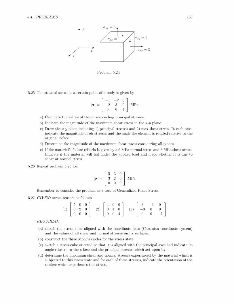
5.4. PROBLEMS 133
x
y
z
σxx = 3
σxy = 1σyx = 1
σyy = 3
Problem 5.24
5.25 The state of stress at a certain point of a body is given by
[σ] =
−1 −2 0
−2 3 00 0 4
MPa
a) Calculate the values of the corresponding principal stresses.
b) Indicate the magnitude of the maximum shear stress in the x-y plane.
c) Draw the x-y plane including 1) principal stresses and 2) max shear stress. In each case,indicate the magnitude of all stresses and the angle the element is rotated relative to theoriginal x-face.
d) Determine the magnitude of the maximum shear stress considering all planes.
e) If the material’s failure criteria is given by a 6 MPa normal stress and 3 MPa shear stress.Indicate if the material will fail under the applied load and if so, whether it is due toshear or normal stress.
5.26 Repeat problem 5.25 for:
[σ] =
5 3 0
3 2 00 0 0
MPa
Remember to consider the problem as a case of Generalized Plane Stress.
5.27 GIVEN : stress tensors as follows
(1)
5 0 0
0 2 00 0 0
(2)
4 0 0
0 4 00 0 4
(3)
3 −3 0
−3 0 00 0 −2
REQUIRED :
(a) sketch the stress cube aligned with the coordinate axes (Cartesian coordinate system)and the values of all shear and normal stresses on its surfaces;
(b) construct the three Mohr’s circles for the stress state;
(c) sketch a stress cube oriented so that it is aligned with the principal axes and indicate itsangle relative to the x-face and the principal stresses which act upon it;
(d) determine the maximum shear and normal stresses experienced by the material which issubjected to this stress state and for each of these stresses, indicate the orientation of thesurface which experiences this stress;
134 CHAPTER 5. STRESS TRANSFORMATION AND MOHR’S CIRCLE
(e) determine the shear and normal stresses that act upon a surface which corresponding toa 30◦ counter-clockwise rotation of the x-face about z-axis.
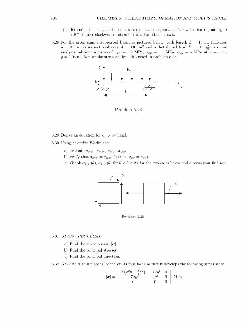
5.28 For the given simply supported beam as pictured below, with length L = 10 m, thicknessh = 0.1 m, cross sectional area A = 0.01 m2 and a distributed load Po = 10 kN
m , a stressanalysis indicates a stress of σxx = −2 MPa, σxy = −1 MPa, σyy = 4 MPa at x = 5 m,y = 0.05 m. Repeat the stress analysis described in problem 5.27.
Po
hx
y
Problem 5.28
L
5.29 Derive an equation for σy′y′ by hand.
5.30 Using Scientific Workplace:
a) evaluate σx′x′ , σy′y′ , σx′y′ , σy′x′
b) verify that σx′y′ = σy′x′ (assume σxy = σyx)c) Graph σx′x′(θ), σx′y′(θ) for 0 < θ < 2π for the two cases below and discuss your findings.
5
10
Problem 5.30
5.31 GIVEN : REQUIRED :
a) Find the stress tensor, [σ].b) Find the principal stresses.c) Find the principal direction.
5.32 GIVEN : A thin plate is loaded on its four faces so that it develops the following stress state.
[σ] =
7
(x2y − 2
3y2)
−7xy2 0−7xy2 7
3y3 00 0 0
MPa
5.4. PROBLEMS 135
10 MPa
5 MPa
y
x3 MPa
Problem 5.31
xxσ
h2
x
yyσ y
L
σ xy
h2
Problem 5.32
REQUIRED :
1) Verify that the conservation of angular momentum and linear momentum are satisfiedunder static conditions, in the absence of body forces, at every point (x, y ) on the plate.
2) Find the components of the traction vector applied on the faces: x = 0, x = L, y = h2 ,
y = −h2
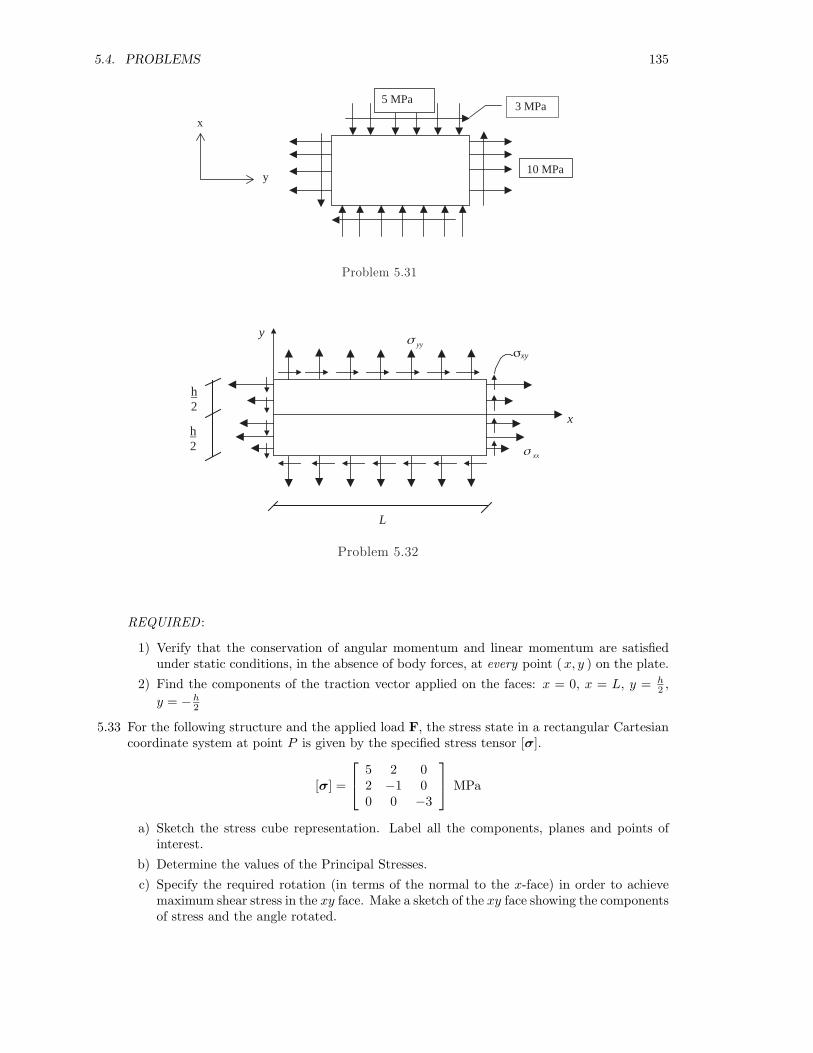
5.33 For the following structure and the applied load F, the stress state in a rectangular Cartesiancoordinate system at point P is given by the specified stress tensor [σ].
[σ] =
5 2 0
2 −1 00 0 −3
MPa
a) Sketch the stress cube representation. Label all the components, planes and points ofinterest.
b) Determine the values of the Principal Stresses.
c) Specify the required rotation (in terms of the normal to the x-face) in order to achievemaximum shear stress in the xy face. Make a sketch of the xy face showing the componentsof stress and the angle rotated.

136 CHAPTER 5. STRESS TRANSFORMATION AND MOHR’S CIRCLE
F
Px
y
z
Problem 5.33
d) According to the material’s properties, the failure criteria is given by a maximum stressof 4 MPa for shear and 6 MPa for normal stress. Predict if the material will fail due tothe applied load. Why?