strategies for sour gas field · pdf filestrategies for sour gas field developments ... saudi...
TRANSCRIPT

1
Strategies for Sour Gas Field Developments
Mahin Rameshni, P.E. Technical Director, Sulfur Technology and Gas Processing WorleyParsons 181 West Huntington Drive, Monrovia, California, 91016 USA [email protected] phone: 626-803-9058
Increasing energy costs and growing demand for natural gas have driven the development of sour gas fields around the world. About forty percent or 2600 Tcf of the world’s natural gas reserves are in the form of sour gas where H2S and CO2 compositions exceed 10% volumetric of the raw produced acid gas. In some cases the acid gas composition in these reserves is very high and economics of producing pipe line quality gas are marginal. Natural gas almost always contains contaminates or other unacceptable components, including heavy hydrocarbons, mercaptans, mercury, water and the acid gases H2S and CO2.
Conditioning natural gas for pipeline LNG or GTL requires the removal of these undesirable contaminants.
Emission regulations are getting tighter and there is increasing demand to achieve higher sulfur removal and recovery.
Middle East counties such as Qatar, Saudi Aramco, and Canada, China, Venezuela, Brazil and many other countries have a high demand to treat sour gas fields.
WorleyParsons has designed over 34 LNG feed gas treating units, over 110 gas processing and gas treating units, over 510 sulfur plants and over 100 tail gas treating units.
The following diagram represents the general scheme for an oil and gas production facility.

2
In general acid gases could be treated using generic solvents such as DGA, DEA, MEA, or MDEA or using proprietary solvents such as aMDEA, Sulfinol, Selexol, Ucarsol, Flexsorb, or other processes from Ryan Homes, BASF, IFP, ADIP, membranes, or molecular sieves options depending on the acid gas compositions and the product specifications considering optimization for affordable capital and operating costs.
For Dew Point Control, water has to be removed to meet the pipe line specifications, by using Glycols, Membranes, or molecular sieves according to the project specification, application, and cost.
Water Injection Wells
LEGEND
OilGasWater
WELLHEADS
Gas
GasCompression
GasDehydration
Natural GasLiquids (NGL)
to Export
Processed Gasfor Conditioning and Reinjection
Injection to Reservoir Gas Caps
Processed Gas for Conditioning and Reinjection
ProducedWater Pumps
Water InjectionWells
SEPARATIONFACILITIES
ProcessedOil
To Export
Oil/Gas/WaterSeparation
UntreatedOil
ProducedWater
Seawater
Sea Water Pumps
Pipelines
Drilling Systems
Manifold
EmergencyFlare
System

3
The primary differences in process by using generic amines are in solution concentrations. MEA is ordinarily used in a 10 to 20 percent by weight in the aqueous solution. DEA is also used in the 10 to 30 percent by weight in the aqueous solution. DIPA, DGA, and MDEA are used in higher concentrations. Typical concentration ranges for DIPA and MDEA are 30 to 50 percent by weight in the aqueous solution. DGA concentrations range from approximately 40 to 50 percent by weight.
As the results of the new revolutions in challenging the various solvents and different process configurations, gas processing in gas industries and refineries has become more complex. In response to this trend and to comply with the product specifications, more equipment and more processing upstream or downstream of gas processing should be implemented.
The selection criteria for gas processing is not limited to the selection of gas treating configurations by itself; it is expanded to the selection criteria of more side process / downstream configurations, to complete the gas processing in order to meet the product specification and to satisfy environmental regulatory agency requirements.
Acid gas removal is the removal of H2S and CO2 from gas streams by using absorption technology and chemical solvents. Sour gas contains H2S, CO2, H2O, hydrocarbons, COS/CS2, solids, mercaptans, NH3, BTEX, and all other unusual impurities that require additional steps for their removal.
There are many treating processes available. However, no single process is ideal for all applications. The initial selection of a particular process may be based on feed parameters such as composition, pressure, temperature, and the nature of the impurities, as well as product specifications. The second selection of a particular process may be based on acid/sour gas percent in the feed, whether all CO2, all H2S, or mixed and in what proportion, if CO2 is significant, whether selective process is preferred for the SRU/TGU feed, and reduction of amine unit regeneration duty. The final selection could be based on content of C3
+ in the feed gas and the size of the unit (small unit reduces advantage of special solvent and may favor conventional amine).
Final selection is ultimately based on process economics, reliability, versatility, and environmental constraints. Clearly, the selection procedure is not a trivial matter and any tool that provides a reliable mechanism for process design is highly desirable.
The variety of the acid gas sources that have different gas compositions, pressure, temperature, and nature of impurities and might require different means of gas processing to meet the product specification, are presented in table I.
Selection of the right tools is very crucial. Establishing and conducting all the elements together at the same time, would generate such a beautiful art in gas treating.

4
Natural Gas Processing
Natural gas is one of the common sources of gas treating, with a wide range in CO2/H2S ratios and high pressure treating. If natural gas is not an LNG application, it could be treated with selective H2S removal if significant CO2 is present. If C3
+ is present, the desirability of using physical or mixed solvents is reduced. If organic sulfur is present, the desirability of using physical or mixed solvents is increased.
It is favored to use proprietary solvents if natural gas has significant CO2 and /or H2S for large units/ and to use conventional solvents for small units particularly with modest acid /sour gas levels.
Petroleum Refining
Petroleum refining is another source of gas treating with low CO2 content, unless the refinery has catalyst cracking unit, in which case the gas may contain COS, organic sulfur, cyanides, ammonia, and organic acids. The acid gas from hydrotreating and hydrocracking essentially contains H2S and ammonia. The gas treating pressures and H2S specifications vary for individual applications, and MEA/DEA/MDEA/DGA or formulated amines are the typical solvents. The refinery typically has multiple absorbers and a common regenerator as listed below:
Fuel gas treating Hydrotreater product/fuel gas Hydrotreater recycle gas Hydrocracker product/fuel gas Hydrocracker recycle gas LPG liq-liq contactor Thermal/catalyst cracker gases Services independent or combined as practical
Synthesis Gas Treatment
Synthesis gas treatment is characterized by high CO2 and low (or no) H2S. If the amount of CO2 is limited, it is preferred to use selective H2S treating via formulated/hindered amine, mixed solvent or physical solvent. If H2S is not present and there is modest or essentially complete CO2 removal, it is preferred to use activated MDEA, hot potassium, mixed amine, and physical solvent.
Table I represents the most common process being used in gas plant industries.

5
Table I- Data Base Outline
HP Gas Treating System, Bulk CO2 Removal from Natural Gas, and Selective H2S Removal Physical Solvent Process (SELEXOL, Murphreesorb, IFPEXOL) Other Solvent Process (DEA, MDEA, DGA, aMDEA, Sulfinol M/D, Flexsorb, Gas/SPEC *SS, Membrane + amine, UCARSOL, Chevron-IPN, Benfield, K2CO3)
Tail Gas Treating (H2S Recycle & Selective Cat. Oxidation Process Typical Solvent (MDEA, HS-101/103, Gas/Spec *SS, Sulfinol, Flexsorb)
BSR /Amine Process Shell SCOT/ ARCO Parsons BOC Recycle
Resulf Dual-Solve BSR / Wet Oxidation
MCRC CBA Sulfreen
BSR /Selectox BSR/Hi-Activity Super Claus
Incinerator Tail Gas
Wellman-Lord Clintox Elsorb
Claus Master Cansolv Bio-Claus
Clausorb
Acid Gas Enrichment Typical Solvent (MDEA, Sulfinol M/D, FLEXSORB, UCARSOL, Gas/SPEC *SS)
Ammonia Plants Physical Solvents, aMDEA, Hot Potassium, Dow 800 series, etc.
Cryogenic Systems Chemical Solvents
Enhanced Oil Recovery (EOR) Chemical & physical Solvents
EOR CO2 Recovery Plants Similar to Bulk CO2 Removal
Ethylene Plants Similar to Bulk CO2 Removal
Flash Regeneration CO2 Removal Similar to Bulk CO2 Removal
Hydrogen Plants Chemicals Solvents
LPG Treating Chemical Solvents
Oil Refinery Systems Chemical & Physical Solvents
Dehydration systems EG, DEG, TEG, Solvents, Methanol, Molecular Sieve Process, etc.
6
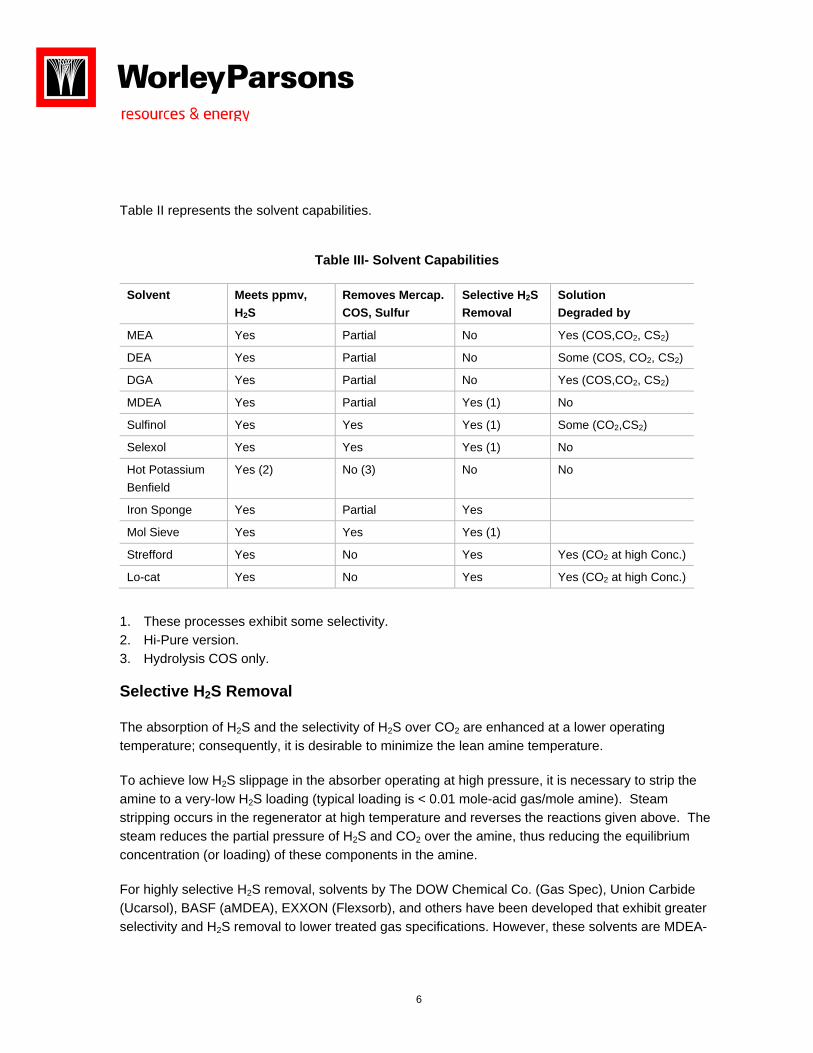
Table II represents the solvent capabilities.
Table III- Solvent Capabilities
Solvent Meets ppmv, H2S
Removes Mercap. COS, Sulfur
Selective H2S Removal
Solution Degraded by
MEA Yes Partial No Yes (COS,CO2, CS2)
DEA Yes Partial No Some (COS, CO2, CS2)
DGA Yes Partial No Yes (COS,CO2, CS2)
MDEA Yes Partial Yes (1) No
Sulfinol Yes Yes Yes (1) Some (CO2,CS2)
Selexol Yes Yes Yes (1) No
Hot Potassium Benfield
Yes (2) No (3) No No
Iron Sponge Yes Partial Yes
Mol Sieve Yes Yes Yes (1)
Strefford Yes No Yes Yes (CO2 at high Conc.)
Lo-cat Yes No Yes Yes (CO2 at high Conc.)
1. These processes exhibit some selectivity. 2. Hi-Pure version. 3. Hydrolysis COS only.
Selective H2S Removal
The absorption of H2S and the selectivity of H2S over CO2 are enhanced at a lower operating temperature; consequently, it is desirable to minimize the lean amine temperature.
To achieve low H2S slippage in the absorber operating at high pressure, it is necessary to strip the amine to a very-low H2S loading (typical loading is < 0.01 mole-acid gas/mole amine). Steam stripping occurs in the regenerator at high temperature and reverses the reactions given above. The steam reduces the partial pressure of H2S and CO2 over the amine, thus reducing the equilibrium concentration (or loading) of these components in the amine.
For highly selective H2S removal, solvents by The DOW Chemical Co. (Gas Spec), Union Carbide (Ucarsol), BASF (aMDEA), EXXON (Flexsorb), and others have been developed that exhibit greater selectivity and H2S removal to lower treated gas specifications. However, these solvents are MDEA-

7
based solvents. These solvents have other applications; such as H2S removal from CO2 enhanced oil recovery (ROR) enrichment processes.
Solvents for H2S selectivity are used for refinery systems with high CO2 slip, tail gas treating, natural gas treating, H2S removal from liquid hydrocarbon streams, natural gas scrubbing, and refinery systems with LPG streams containing olefins.
Bulk CO2 Removal
Solvents for CO2 removal are used for natural gas treaters, landfill gas facilities with high CO2 feed, ammonia and hydrogen plants, and natural gas or LNG facilities with downstream cryogenic facilities. MDEA solvent and mixtures of amines can be used for bulk CO2 removal. However, this performance is very sensitive to one or more of the operating parameters, such as liquid residence time on the trays, circulation rate, and lean amine temperature.
MDEA has a number of properties, which make it desirable for applications such as:
High solution concentration up to 50 to 55 wt % High-acid gas loading Low corrosion Slow degradation Lower heats of reaction Low- vapor pressure and solution losses
Amine solvents and physical solvents are used over a wide variety of process conditions, ranging from atmosphere pressure for refinery off-gas and Claus tail gas treating, to high pressure for natural gas sweetening.
Amine solution in water is very effective at absorbing and holding H2S and CO2 from weak acids, when dissolved in water. The weak acids react with the amine base to help hold them in the solution. Therefore, a chemical solvent (such as amine) is used for these components.
The Hot Potassium Carbonate Process has been utilized successfully for bulk CO2 removal from a number of gas mixtures. It has been used for sweetening natural gases containing both CO2 and H2S. If the gas mixture contains little or no CO2, potassium bisulfide is very difficult to regenerate, and it the Hot Potassium Carbonate Process is not suitable.
The usage of the DGA solvent has been increased recently for the following reasons.
DGA has a higher molecular weight compare to MDEA and higher stability
Capability of absorption of CO2 and H2S

8
Operate at higher concentration, which allows to increase the capacity in existing units and improve the emissions
DGA could be reclaimed thermally as required during normal operation
DGA absorbs H2S and CO2 which means the treated gas meet pipeline specifications, for a better sulfur removal and recovery
Lower capital cost due to capability at higher concentration
DGA has lower heat stable salts rate
DGA has lower degradation product rate
Contaminates Removal As mentioned above, contaminants such as mercury, mercaptans, heavy hydrocarbons, and H2S and CO2 concentrations have to be evaluated carefully in order to select the appropriate solvent to meet the desired product specifications. The contaminants could be removed in front of the gas treating if it is possible or could be done where the product stream leaves the absorber and before the dehydration unit.
Mercaptans are commonly present in natural gas and if the bulk of the mercaptans permitted into the amine plant, due to the mercaptanes solubility in the amine solvent, the lean amine absorbs the mercaptans in the absorber and rich amine leaving the absorber contains some mercaptanes. In the stripper column, a portion of the mercaptans are present in the stripper overhead entering the sulfur plant and it is required to be destructed in the reaction furnace.
Therefore, the selection of the amine solvent in regard to their mercaptans solubility is essential. If the combustion temperature of the reaction furnace is not adequate to destruct heavy hydrocarbons and mercaptans, then several options could be considered as follows.
1. Using Oxygen enrichment to boost the reaction furnace temperature
2. if the H2S concentration of gas to the sulfur recovery unit is low, the acid gas enrichment unit is recommended. Acid gas from the gas-treating unit flows through the acid gas enrichment unit where the H2S has substantially separated from the CO2 and N2. The stream that is enriched in H2S is fed to the sulfur recovery unit while the desulfurized CO2 and N2 stream is sent to the thermal incinerator.
3. Use regenerable activated Carbon Beds downstream of the reaction furnace and upstream of Claus reactors to prevent catalyst deactivation.

9
4. Acid Gas Injection is another option instead of sulfur recovery unit that could be evaluated with a different criteria and the acid gas behavior at high pressure using high pressure compressors.
If COS presents in the treated gas, membranes could be used.
Mercury is another substance commonly present in natural gas, and particularly in LNG facilities it must be removed to meet the product specification. Activated carbon in a non regenerable adsorbent bed is commonly used for mercury removal.
Recent WorleyParsons Experience
WorleyParsons recently evaluated different schemes and solvent for bulk acid gas removal versus selective solvent. Sour Gas Field Developments normally includes amine unit or sulfur removal unit, Dehydration, SRU, TGU and incineration. A typical flow diagram and the process flow diagram for the Case 2 are provided on the following pages.
Two schemes will be described.
Case 1 – our evaluation for new Upgraders and Oil Sands mostly in Canada dealing with a lot of high content H2S and CO2 in sour gas indicates that using DGA solvent in the amine unit will meet the product specification. There will be more CO2 and H2S to the sulfur recovery unit since DGA absorbs most of the H2S and CO2. The Claus unit is then followed by the BSR/TGU-amine tail gas treatment unit. MDEA solvent is selected in the tail gas unit and the evaluation of potential benefits of using selective solvent such as Flexsorb or similar is in progress.
Case 2 - Our evaluation indicates that using common regeneration unit for the amine unit and the tail gas unit is very cost effective in reducing capital and operating cost. The amine unit is designed with a special features of split flow configuration and using turbine to save the electricity where the pressure from the absorber bottom will let down to a lower pressure. TEG is selected for the dehydration unit.
Common Regeneration unit lower operating and capital cost Absorber with split flow configuration Smaller reboiler duty Recover the majority of horse power required by recovering the energy from absorber bottom One solvent, less operating cost Easier to operate
A brief description of our schemes is described below. The sulfur recovery and BSR-TGU is not included since it is typical WorleyParsons design features.

10
(Sulfur Removal) Amine Process Description
The amine unit is an integrated split flow configuration and a common regeneration with the tail gas unit. MDEA flows into the Amine absorber where H2S is preferentially absorbed by the MDEA solution. The MDEA solution reduces the H2S content in the absorber overhead stream to less than 4 ppmv. A 50 wt% MDEA solution is used to treat the acid gas.
The absorber is split into two sections, the absorption section and the water wash section. The absorption section of the tower is trayed with lean solution feed to top of each bed. The absorption section serves as the main contacting section between the gas feed stream and the lean MDEA solution. The water wash section is contained one section and is provided above the lean solution feed point to minimize solvent losses in the treated product stream. A de-entrainment device is also provided above the water wash section of the absorber to minimize the entrainment of liquid out of the top of the absorber in the treated gas. The amine absorber water wash section is integrated in the column shell and provides separation of entrained MDEA and wash water from the overhead gas. Wash water is drawn from the chimney tray top section of the amine absorber, pumped and injected into the absorber top through a flow control valve. Fresh makeup cold condensate is added to the circulating wash water loop and a small purge stream is continuously withdrawn to keep the concentration of MDEA in the wash water relatively low. This minimizes MDEA losses. Treated gas from the Amine absorber overhead gas flows to the dehydration unit.
Rich MDEA leaving the bottom of the absorber operates at high pressure the energy could be recovered as a electricity by providing a turbine to recover the energy. The energy being recovered by the turbine will provide abut 70 to 80% of the required horse power in the sulfur block.
Rich MDEA is sent to the flash drum to remove any hydrocarbon in the solution, by providing a flash section at the top of the drum, then is preheated in the lean/rich MDEA exchanger before entering the regenerator below the wash trays through a flow control valve, which is designed for flashing service.
The amine absorber will have two MDEA streams, one from the Tail Gas Treating Unit absorber as a semi-lean and another from the amine regeneration as a lean solution. This process is integrated split flow configuration that the amine absorber will be provided with the semi-lean and super lean MDEA with a common regeneration that serves TGU absorber and the amine absorber. The circulation rate is reduced and the size of the regeneration is smaller due to less circulation rate. Therefore, the Reboiler and associated equipment will be smaller.
The CO2 and H2S are stripped from the rich MDEA solution in the 24-stripping tray MDEA regenerator by cascading the rich solution, counter-current to steam produced by the Reboiler. The top section of the regenerator tower contains a rectifying (reflux) section consisting of 4 trays for washing of the stripped acid gas. Stripping steam is formed in the Regenerator Reflux Reboiler, and reboiler heat is supplied from the LP steam system. The stripped CO2 and H2S then flow to the sulfur recovery unit. The lean MDEA solution is collected on a chimney tray, which distributes the solution to the reboiler. As the lean solution passes through the reboiler, stripping steam is generated and flows up the

11
column, while the lean solution is returned to the sump section in the base of the column. This stripping steam provides agitation and the heat to release the absorbed H2S and CO2 from the rich MDEA solution, as it rises up through the column, counter-current to the rich MDEA solution. The reboiler is equipped with the Reboiler condensate pot.
The regenerator column consists of a lower stripping section and an upper condensing section. The stripping heat is provided by saturated low-pressure steam through a kettle-type regenerator Reboiler. In the condensing section, the rising vapor is cooled by contact with sub-cooled quench water. The quench water is recycled and cooled. The cooling load is adjusted to control the overhead gas temperature. Overhead gas from the regenerator is recycled to the front of the Claus sulfur recovery unit. A de-entrainment device is provided above the top tray of the tower to minimize the entrainment of liquid out of the top of the regenerator tower into the acid gas stream.
Lean MDEA is pumped through Hot Lean pump then pre-cooled in the lean/rich MDEA exchanger. The MDEA is further cooled in the lean MDEA air cooler and lean MDEA trim cooler. The MDEA storage tank has capacity to hold the total MDEA inventory and is used to take system surges during operation. The tank also serves as a convenient location for MDEA make-up. The MDEA make up from truck connection and cold condensate is provided to the surge tank. Nitrogen blanketing prevents degradation of the MDEA by preventing oxygen to the tank. The cooled lean MDEA is pumped through Lean MDEA circulation pump.
A slip stream of the MDEA is circulated through lean Filter where solid impurities such as iron oxide, iron sulfide, pipe scale, dirt, and degradation products are removed from the solution.
In the Future, after full MDEA filtration, a slipstream may be routed to the Carbon Filter, where soluble MDEA degradation products, more commonly referred to as Heat Stable Salts (HSS), would be removed through adsorption into the carbon active sites. The operation of the Carbon Bed is important to controlling foaming and corrosion in the MDEA unit. Samples of the MDEA solution upstream and downstream of the Carbon Bed should be taken periodically, and the content of Heat Stable Salts should be determined and compared to previous samples. When the capacity of the carbon reaches saturation, inlet and outlet analyses will be indistinguishable. Before this occurs, the carbon should be replaced with fresh charge of activated carbon. The activated carbon in the Carbon Filter will become prematurely saturated with anti-foam constituents instead of the Heat Stable Salt constituents.
Downstream of the rich, lean filtration and on the quench water line to the regenerator, provisions for anti-foam injection are included and should be used only if required. Excess use of anti-foam should be avoided.
The cool, lean, and filtered MDEA solution is returned to the Lean MDEA line and the lean MDEA is routed to the Absorber on flow control valve. The lean MDEA will be routed to two different nozzle locations at the normal operation. A third nozzle connection and a new bed will be considered for future expansion.

12
The collected drain will be routed to the sump, which is a concrete sump under ground. The sump pump is designed to transfer the liquid from the sump to the bottom of the MDEA absorber (or to the Surge Tank). The Filter is located downstream of the pump-out pump. Nitrogen blanketing prevents degradation of the MDEA by preventing oxygen to the sump.
Amine Tail Gas Treating Process Description
Tail gas from the contact condenser flows into the amine absorber where H2S is preferentially absorbed by the amine solution. The amine solution reduces the H2S content in the absorber overhead stream to less than 150 ppmv. The amine solution is a 50-wt% solution of MDEA in water. A packed column is used to minimize the pressure drop through the absorber.
The amine absorber overhead K.O. drum, integral with the absorber column, provides separation of entrained amine and wash water from the overhead gas. Wash water circulated by the wash water pump is injected into the absorber overhead line upstream of the K.O. drum. Fresh makeup condensate is added to the circulating wash water loop and a small purge stream is continuously withdrawn to keep the concentration of amine in the wash water relatively low to minimize amine losses. Tail gas absorber overhead gas flows to the thermal oxidizer for oxidation and release to the atmosphere.
Rich amine is pumped from the bottom of the amine absorber to the amine absorber as a semi-lean solution to the amine absorber. Lean amine is provided from the common regenerator in the amine unit to the TGU absorber.
Incinerator
The gases exiting the amine Absorbers are routed to the Incinerator. Fuel gas is burned with excess air to a sufficient temperature to heat the tail gas from the tail gas unit.
The current design represents a natural draft Incinerator.
The Thermal Oxidizer is designed to oxidize the residual amount of Hydrogen Sulfide (H2S) and other sulfur compounds in the tail gas to Sulfur Dioxide (SO2), and raise the temperature of the waste gas stream from the TGTU to about 1200°F (648 °C). Higher temperature has to be achieved if CO destruction required. Fuel gas and air are combusted in the Thermal Oxidizer and then the waste gas stream (primarily CO2 and N2) is added so that any sulfur compounds are completely oxidized and mixed. The temperature is normally sufficient to oxidize the residual H2S and other sulfur components to SO2, while minimizing SO3 formation. The hot combustion gas exits the facility through the Stack.
The Stack is equipped with an Oxygen/CO/SO2 analyzer, to monitor the excess Oxygen in the Stack gas along with an analyzer, to monitor the Sulfur Dioxide (SO2) content to the Stack gas. In addition to the analyzers, the Stack is equipped with a thermocouple, to monitor the Stack temperature.

13
2. TEG Dehydration Process Description
The Sales gas from the Amine Unit is sent to the Dehydration Unit, for which we have slected TEG as the drying solvent. There are other dehydration processes that could be selected.
The Sales Gas from the each amine Absorber in the acid gas removal is routed to the Dehydration units. The Dehydration TEG Contactor is an absorption column with structure packing. The wet gas is fed to the bottom of the column and the lean TEG is fed to the top of the column. The TEG absorbs water from the wet gas as the two streams are contacted counter-currently in the column. The rich TEG flows to the bottom and is sent to the sales gas dehydration feed/OVHD exchanger to heat the solution prior to entering the Sales gas dehydration TEG flash drum. The rich TEG solution from the flash drum is filtered in the Sales Gas dehydration rich filter.
The rich TEG solution is routed to the TEG Regeneration Unit, which is a package unit through the dehydration lean / rich exchanger. The dried gas exits the top of the column and is sent to the Sales gas dehydration/dry gas/lean solution exchanger, to cool the stripper OVHD gas and heat the dry gas, before it is sent to the sales gas compression.
The basic components in the TEG Regeneration Package are as follows:
Sales Gas Dehydration Regeneration Column is where the water in the rich TEG is stripped off. The Regenerator includes a tray section in part A and a packed column in part B.
Sales gas Dehydration Regeneration Reboiler is a bath type Reboiler. It supplies the heat for stripping via Glycol. It is located directly under the Regenerator Column.
Sales Gas Dehydration TEG Surge Drum directly receives the lean TEG from the Reboiler.
The Sales Gas dehydration regeneration is operated with the dry fuel gas as a strip gas. The fuel gas is introduced to the reboiler through the fuel gas filter. The overhead vapor from the Regenerator Column is cooled by heating the Rich TEG solution with the Sales Gas dehydration TEG Feed/OVHD Exchanger and then is routed to the Sales Gas dehydration Regeneration OVHD KO. Drum to separate the condensate water. The separated gas then is sent to the Sales Gas Dehydration TEG Vent compressor. Condensate water separated from the KO drum is pumped to the sales Gas TEG regeneration. The compressed gas is cooled in the Sales gas Dehydration TEG OVHD Cooler. The condensed water is separated in the Sales Gas Dehydration KO drum and the gas is routed to the CO2 compression unit.
The lean TEG from the sales gas Dehydration regeneration section is sent to the Sales Gas dehydration Lean/rich Exchanger to exchange the heat to the rich solution. The lean TEG solution is further cooled in the Sales Gas dehydration Dry gas/Lean solution exchanger.

14
The lean TEG solution is filtered in the Sales Gas Dehydration Particulate filter. A slipstream from the lean TEG is sent to the Dehydration Charcoal filter and the guard filter respectively. The lean TEG solution is then pumped to the sales Gas Dehydration TEG contactor.
The TEG make-up will be pumped through Sales Gas dehydration TEG make-up pump and the Sales Gas Dehydration TEG sump filter to the Rich TEG solution prior entering the TEG rich flash drum.
A common TEG sump will serve both the Sales Gas dehydration and the CO2 dehydration units to collect the TEG drainage. The solution from the TEG sump is pumped by the Sales Gas Dehydration TEG sump pump, and will be routed to the TEG rich flash drum joining the TEG make-up.
For Case 2 application, the following are the typical feed gas compositions and the product specification for natural gas application in the gas plant.
Component Composition ( % mol )
He 0.01
H2 0.02
N2 0.552
CO2 8.63(2)
H2S 14.14(1)
CH4 76.52
C2H6 0.12
C3H8 0.008
Organic S <150 mg/Nm3
Total 100
Critical Temperature, K 227.65
Critical Pressure, Mpa (a) 5.496
Temperature, °C 25~30
Pressure, Mpa (a) 8.3
It was Assume: H2S content: 13-18%, CO2 content: 8-11%, and Sour feed gas also contains organic sulfur compounds: content of organic sulfur compounds <150mg/m3. Sour feed natural gas is saturated with water and also contains some solid particles (maximum average of 0.2 mg / m3). The treated natural gas will contain less than 6mg/Nm3(20C, 1.013×10⁵Pa) of H2S, less than 3vol % of CO2 and less than 200mg/Nm3(20℃, 1.013×10⁵Pa) of sulfide.
The typical specification of the water dew point of treated natural gas will be -10°C. The Sulfur Recovery Unit shall recover essentially minimum 99.9 wt. percent of the sulfur contained in the feedstock. The vent gas leaving the absorber of the Tail gas treating section shall contains no more than 150 ppmv of sulfide. The liquid sulfur shall contain no more than 10 ppmv of H2S.

15
Refer to Block Flow diagram and the process flow diagram for case 2 study.
Case -3 – WorleyParsons experience on LNG application indicates using activated MDEA is a very cost effective solvent to meet pipeline specifications and followed by dehydration unit to meet the water specifications. A typical LNG feed composition is provided below.
LNG Typical Feed Gas Composition
Component Composition (mol %) CO2 12.76
N2 0.59
CH4 78.86
C2H6 5.50
C3H8 1.92
n-C4 0.18
i-C4 0.12
C5 0.04
C6 0.01
C7 0.00
C8 0.00
C9 0.00
H2S 0.01
Total 100
PROPERTIES
Temperature C 60
Pressure Bara 50
References:
Rameshni, M. “State of the Art in Gas Treating”, presented at British Suphur, 2000, San Francisco, CA, USA.

16
BP Boqueron is an Enhanced Oil Recovery (EOR) project at an existing field located in eastern Venezuela.
WorleyParsons was awarded the project management and construction management services contract by the Saudi Arabian Oil Company (Saudi Aramco) for the Hawiyah Gas Development Project.

17

18

19

20