strategic analysis of the global status of carbon capture ... · the strategic analysis of the...
TRANSCRIPT

Strategic Analysis of the Global Status of Carbon Capture and StorageReport 4: Existing Carbon Capture and Storage Research
and Development Networks around the World
Final Report

This page left intentionally blank

Strategic Analysis of the Global Status of Carbon Capture and Storage Report 4: Existing carbon capture and storage research and
development networks around the world

Strategic Analysis of the Global Status of Carbon Capture and Storage
Page ii
Disclaimer
This report has been prepared by the Electric Power Research Institute (EPRI) on behalf of WorleyParsons Services Pty Ltd (WorleyParsons) for the exclusive use of The Global CCS Institute. It is subject to and issued in accordance with the agreement between The Global CCS Institute and WorleyParsons. Neither WorleyParsons nor EPRI accept liability or responsibility whatsoever for it in respect of any use of or reliance upon this report by any third party.
Copying this report without the permission of The Global CCS Institute or WorleyParsons is not permitted.

Foundation Report FourExisting Carbon Capture and Storage Research and Development Networks Around the World
Page iii
Preface In May 2009 the Global CCS Institute commissioned a WorleyParsons led consortium comprising of Schlumberger, Baker & McKenzie and the Electric Power Research Institute (EPRI) to undertake a Strategic Analysis of the Global Status of Carbon Capture and Storage (CCS).
The Strategic Analysis of the Global Status of CCS will develop six reports. These are:
• an Early Report presenting a high level overview of the key issues and preliminary findings of the study to inform the 2009 G8 Summit held in L'Aquila, Italy, between 8 to 10 July; and
• four foundation reports and a fifth synthesis report that covers:
− a comprehensive survey of all CCS projects being undertaken globally;
− a detailed analysis of the capture, transport and storage costs for power plants and a select range of industrial applications;
− a detailed assessment of the status of policy supporting CCS development globally;
− a comprehensive list and analysis of existing Research and Development (R&D) networks (government, academia, industry and institute) involved in CCS; and
− a comprehensive assessment of the gaps and barriers to the global deployment of large scale CCS projects.
This report presents a comprehensive list and analysis of existing Research and Development (R&D) networks around the world (Foundation Report Four).

Strategic Analysis of the Global Status of Carbon Capture and Storage
Page iv
Acknowledgements The Strategic Analysis of the Global Status of Carbon Capture and Storage was undertaken by a WorleyParsons led consortium of Schlumberger Capture Services (SCS), Baker & McKenzie and the Electric Power Research Institute (EPRI).
The overall project was sponsored by Peter Brooks (WorleyParsons) and the Project Manager was Chai McConnell (WorleyParsons).
WorleyParsons would like to acknowledge the Global CCS Institute for funding this study and particularly the efforts of Andrew Roden (Project Manager).
This particular report was produced by EPRI. Jose Marasigan and Jeff Phillips were the lead authors of this report. Assistance with this report was also provided by Giovanni Sosio, Laurent Jammes and Sandeep Sharma (Schlumberger).
This report was reviewed by Chai McConnel and Haruo Kikkawa (WorleyParsons). It was peer reviewed by Dr Kelly Thambimuthu, Kamel Bennaceur and Peta Ashworth.
WorleyParsons would like to acknowledge the CO2CRC for supplying graphics for the report with additional graphic support provided by Andrew Barker and Anthony Holt (WorleyParsons).
Strategic Analysis of the Global Status of Carbon Capture and Storage Report 4: Existing Carbon Capture and Storage Research and Development Networks around the World Final Report © 2009 Global CCS Institute.
For general enquires about this or any of the foundation reports, please contact the Global CCS Institute, GPO Box 828, Canberra ACT 2601 Australia or email [email protected]

Foundation Report FourExisting Carbon Capture and Storage Research and Development Networks Around the World
Page v
Contents Abbreviations....................................................................................................................................... ix
1. Executive summary .............................................................................................................. 1
1.1 Background....................................................................................................................... 9
1.2 Purpose .......................................................................................................................... 11
1.3 Scope.............................................................................................................................. 11
2. Methodology........................................................................................................................ 13
2.1 CCS R&D database development .................................................................................. 13
2.2 Limitations....................................................................................................................... 13
3. Assessment of the networks and their activities ............................................................ 15
3.1 CCS technologies development status........................................................................... 15
3.2 Trends............................................................................................................................. 18
4. Gaps in R&D ........................................................................................................................ 22
4.1 Background for the R&D gap analysis............................................................................ 22
4.2 Proof of large-scale sequestration.................................................................................. 25
4.3 CO2 transportation gaps ................................................................................................. 31
4.4 R&D gaps for CO2 compression..................................................................................... 33
4.5 R&D gaps for CO2 capture from power generation ........................................................ 34
4.6 R&D gaps for CO2 capture from industrial sources........................................................ 43
4.7 Non-commercial gaps..................................................................................................... 54
5. Exemplary R&D networks .................................................................................................. 57
5.1 Australia and New Zealand (ANZ).................................................................................. 57
5.2 European Union, Middle East and Africa........................................................................ 61
5.3 Americas......................................................................................................................... 66
5.4 Asia-Pacific ..................................................................................................................... 73
5.5 Industrial CCS network................................................................................................... 75
6. Monitoring the networks .................................................................................................... 77
6.1 TRL-9, full-scale commercial deployment ...................................................................... 77
6.2 TRL-8, sub-scale commercial demonstration plant ........................................................ 78
6.3 TRL-7, pilot plant ............................................................................................................ 78
6.4 TRL-6, component prototype demonstration.................................................................. 79
6.5 TRL-5, component prototype development .................................................................... 79

Strategic Analysis of the Global Status of Carbon Capture and Storage
Page vi
6.6 TRL-4, laboratory component testing ............................................................................. 80
6.7 TRL-3, Analytical, “Proof of Concept” ............................................................................. 80
6.8 TRL-2, application formulated......................................................................................... 80
6.9 TRL-1, basic principles observed ................................................................................... 80
7. Conclusions......................................................................................................................... 82
7.1 Next steps ....................................................................................................................... 84
8. References ........................................................................................................................... 85

Foundation Report FourExisting Carbon Capture and Storage Research and Development Networks Around the World
Page vii
List of figures Figure 1-1 Number of organisations per region and type of R&D coverage performed....................... 2
Figure 1-2 TRL summary of technologies and sectors analysed ......................................................... 9
Figure 1-3 Estimated contribution by sector to global anthropogenic CO2 emissions........................ 10
Figure 3-1 Number of organisations per region and type of R&D coverage performed..................... 18
Figure 3-2 Number of organisations researching and developing CCS technologies........................ 19
Figure 4-1 Timescale for capture process development .................................................................... 24
Figure 4-2 Technology development and leaky pipe analogy ............................................................ 25
Figure 4-3 Generic absorption/stripping process for flue gas removal of CO2 ................................... 36
Figure 4-4 Schematic of oxyfuel combustion process ........................................................................ 38
Figure 4-5 Generic diagram of IGCC with CO2 capture...................................................................... 41
Figure 4-6 Battelle’s cost estimates for capturing and compressing CO2 from various sources (2006 US$ basis) .............................................................................................................. 51
Figure 4-7 Net cost of employing CCS in the USA based on current technologies and sources ............................................................................................................................. 52
Figure 5-1 CO2CRC Otway project location....................................................................................... 58
Figure 5-2 ANLEC R&D’s relationships with key organisations and activities nationally and internationally.................................................................................................................... 60
Figure 5-3 Timeline for the US DOE regional sequestration partnership demonstrations .................. 72
Figure 6-1 Histogram showing distribution of TRLs of post-combustion capture technologies........... 81

Strategic Analysis of the Global Status of Carbon Capture and Storage
Page viii
List of tables Table 1-1 Storage matrix ........................................................................................................................ 6
Table 1-2 The nine technical readiness levels ....................................................................................... 7
Table 3-1 CCS application matrix......................................................................................................... 16
Table 4-1 The nine technical readiness levels for technology deployment.......................................... 23
Table 4-2 Select existing and planned CO2 storage projects as of early 2009 ..................................... 26
Table 4-3 Storage matrix ...................................................................................................................... 28
Table 5-1 Regional Carbon Sequestration Partnerships (RCSP) – development tests....................... 68
Table 5-2 CO2 Capture Project participating organisations.................................................................. 75

Foundation Report FourExisting Carbon Capture and Storage Research and Development Networks Around the World
Page ix
Abbreviations
ADM Archer Daniels Midland
AEP American Electric Power
AGR acid gas removal
ANLEC R&D Australian National Low Emissions Coal Research and Development
ANZ Australia and New Zealand
APP Asia-Pacific Partnership on Clean Development and Climate
Ar argon
AR4 IPCC Fourth Assessment Report on Climate Change 2007
ASU air separation unit
bbl barrels (of oil)
BOF basic oxygen furnace
BSCSP Big Sky Regional Carbon Sequestration Partnership
B&W Babcock & Wilcox
CaCO3 calcium carbonate (limestone)
CaO calcium oxide (lime)
CAP chilled ammonia process
CCP CO2 Capture Project
CCS carbon capture and storage
CFBC circulating fluidised bed combustion
CFZ controlled freeze zone
CLC chemical looping combustion
CO carbon monoxide
CO2 carbon dioxide
CO2CRC Cooperative Research Centre for Greenhouse Gas Technologies
COE cost of electricity
COS carbonyl sulphide
CPPL CO2CRC Pilot Project Ltd
CRC Cooperative Research Centres (Program)
CSIRO Commonwealth Scientific and Industrial Research Organisation
CURC Coal Utilisation Research Council

Strategic Analysis of the Global Status of Carbon Capture and Storage
Page x
CW cooling water
DNV Det Norske Veritas
DOE-NETL (US) Department of Energy – National Energy Technology Laboratory
DRI direct iron ore
ECBM enhanced coal bed methane
ECRA European Cement Research Academy
EOR enhanced oil recovery
EPC engineer, procure and construct
EPRI Electric Power Research Institute
ESP electrostatic precipitator
ETIS Energy Technology Innovation Strategy
EU European Union
E&P exploration and production (of oil)
FCC fluid catalyst cracker
FG flue gas
FGD flue gas desulphurisation
ft feet or foot
G8 Group of Eight
GE General Electric
GHG greenhouse gas
GHGT-9 9th International Conference on Greenhouse Gas Technologies
Gt gigatonnes
G-CEP Stanford University Global Climate and Energy Project
H2 hydrogen
H2S hydrogen sulphide
HRSG heat recovery steam generator
HSE health, safety and environment
Hz hertz
IEA
IEA GHG
International Energy Agency
International Energy Agency Greenhouse Gas R&D Program
IGCC integrated gasification combined cycle
IHEA IHI Engineering Australia
Foundation Report FourExisting Carbon Capture and Storage Research and Development Networks Around the World
Page xi
IHI Ishikawajima-Harima Heavy Industries Co., Ltd
IISD International Institute for Sustainable Development
IJV incorporated joint venture
IOGCC Interstate Oil and Gas Compact Commission
IPCC Intergovernmental Panel on Climate Change
ISEEE Institute for Sustainable Energy, Environment and Economy
ITM ion transport membrane
IURC Indiana Utility Regulatory Commission
JCOAL Japan Coal Energy Centre
JCOP Japan CO2 Sequestration in Coal Seams Project
JV joint venture
km kilometre
kT kilotonnes
kW kilowatt
LNG liquefied natural gas
m metre
MAC main air compressor
MEA monoethanolamine
METI Ministry of Economy, Trade and Industry
MgO magnesium oxide
MGSC Midwest Geological Sequestration Consortium
MgSiO3 magnesium silicate
MHI Mitsubishi Heavy Industries
MMV measurement, monitoring and verification
MPa megapascal
MRCSP Midwest Regional Carbon Sequestration Partnership
MT megatonnes (million tonnes)
mt/yr metric tons per year
MW megawatt
MWe megawatt electrical
MWth megawatt thermal
N2 nitrogen

Strategic Analysis of the Global Status of Carbon Capture and Storage
Page xii
NEDO New Energy and Industrial Technology Development Organisation
NGCC natural gas-fired combined cycle
NGO non-governmental organisation
NH3 ammonia
NLECC National Low Emissions Coal Council
NLECI National Low Emissions Coal Initiative
NO nitric oxide
NO2 nitrogen dioxide
NOx nitrogen oxides
O2 oxygen
OPEC Organisation of Petroleum Exporting Countries
PC pulverised coal
PCOR Plains CO2 Reduction Partnership
PHMSA U.S. Department of Transportation’s Pipeline and Hazardous Materials Safety Administration
ppm parts per million
PSA pressure swing absorber
PTRC Petroleum Technology Research Centre
R&D research and development
RD&D research, development and demonstration
RFG recycled flue gas
RSA Republic of South Africa
SACROC Scurry Area Canyon Reef Operators Committee
scf standard cubic feet
SECARB Southeast Regional Carbon Sequestration Partnership
SiO2 silicon dioxide
SMR steam methane reforming
SMV storage monitoring and verification
SNG substitute natural gas
SO2 sulphur dioxide
SRI SRI International
SWP Southwest Regional Partnership for Carbon Sequestration

Foundation Report FourExisting Carbon Capture and Storage Research and Development Networks Around the World
Page xiii
Synfuel synthesis fuel
Syngas synthesis gas
TAME The Andersons Marathon Ethanol, LLC
TPC total plant cost
TRL technical readiness level
UAE United Arab Emirates
UK United Kingdom
ULCOS Ultra-Low CO2 Steelmaking
US United States of America
US DOE US Department of Energy
US EPA US Environmental Protection Agency
WESTCARB West Coast Regional Carbon Sequestration Partnership
WRI World Resources Institute

This page left intentionally blank

Foundation Report FourExisting Carbon Capture and Storage Research and Development Networks Around the World
Page 1
1. Executive summary
Carbon capture and storage (CCS) has significant potential to decrease anthropogenic carbon dioxide (CO2) emissions. It could be applied on fossil fuel and biomass-based power generation, oil and gas production and processing, and the production of hydrocarbon chemicals, minerals (eg, cement and glass) and metals. If it were applied to all of these applicable sectors, CCS would have the potential to decrease roughly two-thirds of anthropogenic CO2 emissions worldwide. In addition, CO2 emissions from the transportation sector could be significantly reduced if centralised plants producing decarbonised electricity and/or hydrogen would fuel a transformed transportation infrastructure.
The Global Carbon Capture and Storage Institute (Global CCS Institute) was established to accelerate the commercial deployment of CCS projects and to ensure that the technology plays an integral part of the portfolio required to make significant reductions in the level of CO2 emissions. A key element in this process is to establish sufficient confidence in the technology through the establishment of a series of large-scale integrated CCS demonstration projects. This need for early large-scale CCS demonstration has been recognised politically and is exemplified by the Group of Eight (G8) to launch 20 fully integrated large-scale CCS projects globally by 2010 to enable broad deployment by 2020.
It has been estimated that worldwide CO2 storage rates need to reach 250 million tonnes annually by 2020, and more than 10 times this magnitude by 2050 in order to stabilise atmospheric concentrations of CO2 at no more than 450 parts per million (ppm) (Kerr & Burnard 2009). The current storage rate of CO2 from anthropogenic sources is less than 25 million tonnes per year. Thus, emission reduction schemes such as CCS need to increase by at least an order of magnitude in the next 11 years, and a further order of magnitude over the next 30 years thereafter to reach the targeted CO2 concentration level.
The purpose of this Fourth Foundation Report is to support the objective of accelerating the development of CCS technologies by identifying and assessing notable research and development (R&D) activities being performed by organisations worldwide. This screening process helped reveal which organisations have the most advanced and comprehensive R&D programs to meet this objective. This process also identified significant gaps in the current global R&D effort.
Due to the importance of independent R&D efforts as well as those of collaborative networks, in the context of this report and its associated database, it was decided that a CCS R&D “network” may either consist of several organisations linked with a common set of goals or a single entity (eg, an individual company or university) performing remarkable R&D work.
There are currently hundreds, if not thousands, of organisations worldwide engaged in some aspect of CCS R&D. To narrow the focus of this study, a list of organisations undertaking considerable R&D in their respective areas of expertise was compiled through a panel of advisors, including key Electric Power Research Institute (EPRI) and WorleyParsons staff as well as outside consultants. It should be noted that this list was not intended to be a comprehensive list of all the organisations involved in CCS R&D, but it is believed to be representative of the global effort and includes most, if not all, of the key on-going R&D projects.
Upon establishing the list of networks, the process of researching the various organisations commenced. Sources of public data collected include websites of the organisations, telephone calls of a non-proprietary nature with contacts at the organisations, and publicly available technical conference papers and presentations. Questionnaires were also sent to the organisations in an effort to gather

Strategic Analysis of the Global Status of Carbon Capture and Storage
Page 2
additional information not found in sources cited above, but the response rate to the questionnaire was disappointingly low.
357 different organisations have been identified for inclusion in the R&D Networks database. Figure 1-1 illustrates the regions to which the organisations belong and the type of R&D coverage being performed.
Figure 1-1 Number of organisations per region and type of R&D coverage performed
0
50
100
150
200
Num
ber
of N
etw
orks
F 2 3 4 1 1 1 11 1 4 1 1 1 19
E 3 3 6 3 4 2 15 3 4 2 2 2 12
D 2 5 5 2 2 1 11 1 4 1 1 2 27
C 11122422
B 5161152
A 13 28 34 11 12 5 91 5 18 3 3 4 125
Africa ANZ Canada ChinaEast Asia
(ex. Japan)
East Europe
Euro AreaIndia Area
JapanMiddle East
Pacific Islands
South America
USA
F - Political Regional and Environmental IssuesE - Information SharingD - Public Awareness and UnderstandingC - EconomicsB - RegulationsA - CCS Technologies
TOTAL 24 41 58 18 18 20 9 24 32 7 7 10 209 Source: EPRI, 2009
In many cases, an organisation is involved in more than one R&D coverage area, and this is reflected in the preceding chart by counting them in their applicable R&D areas. Consequently, the total number of organisations in the table add up to more than 357 as stated previously.
TRENDS AND GAPS
It is clear from Figure 1-1 that most of the networks in the database are focusing their R&D efforts on CCS technologies. Among the three main CO2 capture technologies, the data revealed that post-combustion capture R&D is receiving the most emphasis, followed by oxy-combustion and then pre-combustion capture. In most regions, the emphasis on CO2 sequestration R&D is proportionately similar to that devoted to post-combustion capture R&D.

Foundation Report FourExisting Carbon Capture and Storage Research and Development Networks Around the World
Page 3
A great majority of the CO2 capture R&D is focused on the power generation sector, particularly coal-fired power generation. Given the fairly sizeable contribution that cement production makes to anthropogenic CO2 emissions, a disproportionately small R&D effort is focused on CO2 capture from cement production. While there is a significant effort based in Europe focusing on CO2 capture from iron and steel production, the overall effort in this sector is disproportionately small as well. By contrast, the CCS R&D efforts in oil and gas production and processing appear to be quite steady.
Even within the coal power CO2 capture R&D efforts, the vast majority of the projects are focused on the early stages of R&D and have not yet reached the small pilot plant size. In the main report, it is shown that in order to have CCS technologies deployed at full commercial-scale by 2020, it will be necessary to have capture technologies operating on realistic conditions, at least on a small pilot scale, by 2010. It appears that this is happening, but a major challenge will be finding the funds to pay for scale-up beyond the small pilot plant size.
There are a number of technologies around the world in the early stages of development that could provide reductions in the capital cost and energy penalties currently associated with post-combustion capture. There appears to be sufficient funding available to elevate these technologies to the small pilot plant level, but technology developers will need financial support if they are to scale-up these technologies to the sub-commercial scale demonstration and ultimately full-scale commercial sizes. This is a key gap in post-combustion CO2 capture R&D.
Oxy-combustion capture stands to benefit from developments in oxygen separation such as membrane-based air separation technology, which could replace the energy-intensive cryogenic process air separation technology. This is a R&D gap, as the survey identified only a small number of projects aimed at reducing the cost of oxygen production. In addition, as is the case with post-combustion capture, oxy-combustion developers are building small pilot plants, but they will need outside funding to support scale-up to larger sizes.
Pre-combustion CO2 capture is being practiced at large-scale in the chemicals production, oil refining and natural gas processing sectors, and three major suppliers of gas turbines are all currently willing to offer their large “F class” firing temperature (1300ºC) machines for pre-combustion capture applications in integrated gasification combined cycle (IGCC) plants. As a result, it appears this technology is applicable today for commercial-scale demonstrations in IGCC plants with pre-combustion capture. However, there is still the need to foster cost reductions, and an important route to cost reductions in IGCCs is to increase the gas turbine efficiency. Accelerating the development and testing of gas turbines with efficiencies higher than the “F class” units for pre-combustion capture in IGCC plants by 2020 is a key R&D gap.
Improvements in CO2 compression have only recently begun receiving attention. While CO2 compression has been deployed at large-scale, it is now recognised that there is potential for improving the efficiency and perhaps the cost of the compression equipment. In addition, application of CCS to sectors outside of oil and gas production will bring new challenges in terms of potential co-constituents in the CO2 stream as well as different operating pressures and variable flow rates. A key R&D gap is the need to obtain better thermodynamic data on CO2 mixtures at, and near, supercritical conditions with anticipated impurities from the various capture applications.
The R&D efforts for CO2 transportation are modest compared to those for capture or storage. This is due in part to the fairly mature status of CO2 transportation. However, the scale of CO2 transportation that will be required with widespread deployment of CCS is two or three orders of magnitude greater than what is currently in place. The small R&D efforts that are taking place appear to be exclusively focused on pipelines as opposed to ocean tankers, road or rail transport. Some research is taking
Strategic Analysis of the Global Status of Carbon Capture and Storage
Page 4
place to examine the optimum way to develop regional CO2 pipeline systems, and an R&D network based in Europe has started identifying key CO2 pipeline R&D needs. As is the case with CO2 compression, a key gap is the need for better models to predict thermodynamic data of the transported supercritical fluid, especially when impurities are present.
CO2 storage research is currently trending away from deep ocean storage and processes that require the CO2 to be reacted with other materials (eg, mineralisation). Focus has shifted to deep geological storage in saline formations as well as alternative geological storage options such as oil and gas reservoirs, unmineable coal seams and basalt formations. There is, however, increased focus on biological fixation mechanisms such as the production of algae. The latter has attracted attention because the algae could potentially be converted into a biofuel and therefore would not be a “throw away” product. However, many challenges to the widespread deployment of algae production exist, not the least of which is the large land requirement.
Geological storage R&D is focused on conducting tests in various geological strata and on developing and proving techniques for monitoring CO2 in those strata. Clearly this effort must continue in earnest if CCS is to begin commercial-scale deployment in 2020. While the experiences gained from existing large-scale CO2 storage projects provide confidence that geological storage is possible, it does not by itself open the door for widespread deployment of CCS. Due to regional variations in geology, it is important to conduct similar tests in multiple regions around the world. Projects in multiple locations also help build public confidence and acceptance in a wider-spread fashion.
Beyond actual storage tests, insufficient R&D effort is focused on decreasing the cost of finding, developing and operating geological storage sites for CO2. Techniques for reducing the costs of characterising storage sites are a critical R&D gap. Not only is characterisation a significant up-front cost, a thorough characterisation could take up to three years to complete and may end with the conclusion that the site is unsuitable for storage. At this point, few commercial entities will want to take this financial risk and will instead delay the decision to implement a CCS project. More research is needed to identify the appropriate business structures that will facilitate the implementation of large-scale commercial CO2 storage activities.
Outside of R&D on CCS technologies, Figure 1-1 shows that public awareness and understanding has the most number of organisations involved in non-technical R&D efforts. This trend is expected to grow as CCS projects become larger and more prevalent. As is discussed in the main body of the report, some CO2 storage projects have been postponed, moved or cancelled recently due to opposition from the local public. Research has demonstrated that presenting a comprehensive public awareness and/or education campaign will enable the public to form their own more informed opinions about CCS. Although this does not always lead to acceptance, it does assist in creating a more positive attitude towards the technology. This is particularly important because once formed, opinions can be slow to change. A recent community engagement workshop held by the World Resources Institute (WRI) concluded, among others, that there is a need for more government funding for research on CCS public awareness by conducting surveys, focus groups and public awareness workshops. This will not only outline but potentially lead to public acceptance for successful CCS demonstrations.
In terms of geographic distribution, CCS R&D in Asia lags the efforts undertaken by the European Union (EU) and Americas. Although some networks have engaged several Indian and Chinese universities in R&D activities, additional collaboration between Asian networks and networks from Australia and New Zealand (ANZ), EU and Americas is needed to close this gap.

Foundation Report FourExisting Carbon Capture and Storage Research and Development Networks Around the World
Page 5
In assessing the degree of networking among the organisations in the database, it was determined that roughly 55 percent of the entries were single-entity “networks” while 45 percent were formal, multi-entity collaborations. The median value of collaborating organisations in the multi-entity networks was three. Consequently it appears that most of the CCS R&D is being conducted by independent entities or small collaborations of two or three organisations. While independent R&D is often the source of technology breakthroughs, it is also the case that technology development can be accelerated by learning from the successes and failures of others. Therefore, it is recommended that the Global CCS Institute investigate options for fostering greater networking among the many entities that are conducting CCS R&D worldwide without imposing a structure that could stifle independent creativity.
The current economics of CCS is such that the cost of emitting CO2 from coal-fired power plants is still less than the cost of implementing CCS anywhere in the world today. Recent assessments by Australian, European and United States of America (US) organisations have shown that the use of CCS to limit CO2 emissions from coal-fired power plants using current state-of-the-art technology will result in an avoided emissions cost of US$36 to US$78 per tonne (2007 US$ basis), and the cost of implementing CCS on natural gas combined cycle (NGCC) plants will result in avoided emissions costs of US$88 to US$104 per tonne. These numbers are based on the cost of including CCS on a new power plant. The cost for retrofitting CCS to an existing coal-fired power plant is expected to be 30 percent higher or more. Cost estimates for industrial applications of CCS vary widely depending on the application. In some industrial applications such as ethanol fermentation and ammonia production, a high purity CO2 stream is already produced as part of the manufacturing process. The cost of applying CCS to these applications is relatively low. For other applications such as oil refining, there are a number of smaller, dilute CO2 sources from which it would be relatively expensive to separate and compress a high purity CO2 stream. CO2 emission credits during the first eight months of 2009 have traded between 12 and 16 Euros (circa US$17 to US$22 at US$1.4/Euro), which is considerably less than the cost of implementing CCS on a new pulverised coal (PC) or IGCC power plant as well as other major industrial CO2 emission sources. Consequently, in order for there to be a financial incentive to deploy CCS, technology improvements must yield cost reductions, market prices must rise or a combination of both these scenarios must occur.
EXEMPLARY NETWORKS
While researching the networks and populating the database, certain networks stood out from the rest in terms of R&D efforts. A dedicated chapter in the main report (Section 5) identifies these networks and provides detailed descriptions of their R&D activities. The exemplary networks include:
• Cooperative Research Centre for Greenhouse Gas Technologies (CO2CRC) Otway and H3 Capture Projects;
• Australian Coal Association and Australian National Low Emissions Coal R&D Ltd.;
• IEA Greenhouse Gas R&D Programme;
• World Resources Institute;
• US Department of Energy (US DOE) Regional CO2 Sequestration Partnerships;
• Asia-Pacific Partnership for Clean Development and Climate;
• Japan Coal Energy Centre; and
• CO2 Capture Project.

Strategic Analysis of the Global Status of Carbon Capture and Storage
Page 6
The efforts planned by the US DOE Regional Sequestration Partnerships merit particular mention. A total of nine demonstration projects are being planned by the seven partnerships; each project will store at least one million tonnes of CO2. Eight of the projects will utilise saline reservoirs for CO2 storage, and the ninth is an enhanced oil recovery (EOR) application. A combined timeline for the nine US DOE regional partnership storage demonstrations is shown in Figure 5-3. The first demonstration began earlier this year (SECARB’s Cranfield site). By the end of 2010, three additional demonstrations should be injecting CO2. By the end of 2017, all nine demonstrations will be completed and a total of more than 19 million tonnes of CO2 will have been stored in a variety of geological formations. It will be important that the lessons learned from these large-scale storage projects as well as the knowledge gained from the other exemplary R&D networks are shared around the world. The Global CCS Institute can serve as the catalyst for disseminating that knowledge.
MONITORING CCS R&D PROGRESS
In order to monitor the networks’ progress towards the commercial deployment of CCS globally, it is proposed that the CCS Application Matrix shown in be used to provide a high level overview. In order to facilitate widespread deployment of CCS across all applicable sectors, ideally all of the cells in need to be shaded green by 2020, which would indicate that all aspects of the CCS supply chain have been demonstrated at commercial-scale volumes in all the sectors. This will be a tall order. A more realistic goal might be to have at least one capture, one compression, one transport and two storage cells shaded green for each application by 2020 and a majority of the other cells shaded yellow (meaning sub-commercial scale operation has been demonstrated).
It is also important to monitor CCS deployment across regions of the world. Table 1-1 shows the current annual rate of CO2 injection into geological media. The Global CCS Institute should update this data on a yearly basis to monitor the rate of CCS progress around the world.
Table 1-1 Storage matrix
Current annual storage rate, tonnes of CO2
Region Onshore saline
Offshore saline
Oil/gas reservoir Basalt Coal seam
Americas 65,000 48,000,000 900 70,000
Europe 125,000 1,000,000 700,000
Africa 1,300,000
Asia 10,0001
ANZ 65,000
Note 1: 10,000 tonne per year test injection was conducted near Nagaoka, Japan in 2004, but injection ended in 2004.
While Table 3-1 and Table 1-1 will provide high level measurements on the progress of CCS, it is also recommended that the Global CCS Institute consider adopting the Technical Readiness Levels (TRLs) concept to catalogue information on the state of CCS. This approach can be particularly useful in tracking the status of individual technologies in the earlier stages of the R&D timeline. The nine TRLs are listed in Table 1-2.

Foundation Report FourExisting Carbon Capture and Storage Research and Development Networks Around the World
Page 7
The achievement of a given TRL will inform process developers and customers on the advice necessary to commit the resources required to achieve the next level of readiness. An achievement of TRL-9 indicates that the technology can be deployed with risks that are comparable to those undertaken on other “commercial” technologies that are commonly deployed. Only customers who are able to take on higher risks will be suitable participants in efforts to achieve the TRLs up to and including TRL-9.
Table 1-2 The nine technical readiness levels
TRL-9 Full-Scale Commercial Deployment
TRL-8 Sub-Scale Commercial Demonstration Plant
TRL-7 Pilot Plant
TRL-6 Component Prototype Demonstration
TRL-5 Component Prototype Development
TRL-4 Laboratory Component Testing
TRL-3 Analytical, “Proof of Concept”
TRL-2 Application Formulated
TRL-1 Basic Principles Observed
In the mid-20th century, coal-fired power plants had no controls for sulphur dioxide (SO2), nitrogen oxides (NOx) or mercury emissions. Throughout the last 50 years, various technologies to control these pollutants have progressed from about TRL-4 to multiple commercial installations. This experience has shown that the achievement of TRL-9 can take approximately 20 years. This long development time is largely dictated by design and construction activities associated with the field deployment of pilot plants (to achieve TRL-7), commercial pilot plants (to achieve TRL-8) and the first full-scale, commercial installation (TRL-9).
To a certain extent, the overall development times may be shortened by committing resources for a pilot plant, demonstration or full-scale deployment concurrent with activities designed to achieve TRLs lower on the ladder. Commercial or other considerations may recommend such a “fast-track” approach. It is often the case, however, that the effort to achieve a TRL lower on the ladder will reveal process design, operation or maintenance requirements that were not apparent at the beginning. Indeed, this is one of the major motivations for undertaking an orderly approach to technology development; it is likely to be less expensive in cost and time to implement remedies for such uncovered requirements at a modest scale than at a larger scale.
Experience has shown that passing over any of the development steps up the TRL ladder will increase the likelihood of failing to achieve the targeted TRL and may eventually necessitate returning to the skipped TRL before progressing further. The time required to design, deploy and operate facilities to achieve specific TRLs increases significantly as the TRL increases. If multiple CCS demonstrations with improved technologies are to be achieved at large-scale (ie, TRL-9) by 2020 to proceed with

Strategic Analysis of the Global Status of Carbon Capture and Storage
Page 8
commercial deployment, then many technologies need to be approaching the pilot plant stage (TRL-7) today. However, our review of the data revealed that there are very few organisations funding demonstrations at one-tenth to full commercial-scale. While this may not currently be constraining the advancement of improved CCS technologies, it soon will. Applications of CO2 capture for the oil and gas and power sectors appear to be receiving enough funding to achieve pilot plant scale, but advancing to sub-commercial scale demonstrations and larger will require an order of magnitude greater level of funding. Figure 1-2 summarises the current technical readiness of some of the main technologies and sectors covered in this report.
CONCLUSIONS
The purpose of the Fourth Foundation Report is to identify networks performing notable R&D in the area of CCS and to summarise the work with which they are involved. To support these report objectives and to facilitate the assessment of the global status of CCS R&D, a database of organisations performing considerable CCS R&D was developed. Based on inputs from the panel of advisors for this project, 357 organisations were identified for inclusion in the R&D Networks database. However, several factors resulted in the omission of some key information from the database, limiting the types of analyses that can be performed and preventing any definitive conclusions that can be drawn from the data. Despite these limitations, the authors believe that the R&D activities captured in the database are a fair representation of the global effort on CCS R&D. Omissions in the data were overcome by a qualitative assessment of the R&D activity based on the authors’ and reviewers’ knowledge of ongoing worldwide CCS R&D.
Based on the assessment of the data, CCS is not ready for commercial-scale deployment in many of its potentially applicable sectors. In addition, CO2 storage has not been demonstrated at the required scale in many of the geographic regions and geological strata where CCS may be implemented. Consequently, the development of many CCS technologies must be accelerated if a global commercial-scale deployment of CCS is to commence by the end of the next decade.
FUTURE WORK
During the course of preparing this report, 357 organisations have been identified for inclusion in the CCS R&D Networks database. CCS R&D is being conducted by many organisations, and the database should be updated periodically to include additional organisations or networks contributing to CCS deployment. In addition, in many cases, publicly available data on the organisations in the database were limited, and additional effort is needed to gather new and more complete information.
It may be possible to improve the database to “map” an individual organisation to a network. This could identify the important nodes that coordinate research across various areas as well as priorities and gaps. Improving the usability of the database is one area for future consideration.
The networks involved in CO2 sequestration can be categorised by the different formations being researched, including separate categories for EOR and enhanced coal bed methane (ECBM). Attention should also be given to CO2 storage working in tandem with water recovery to provide more sustainable solutions in arid regions. Removal of water could increase the capacity of saline reservoir storage, and saline reservoirs provide the largest potential storage capacity globally for CO2.
There is also a need to gather and distribute accurate and up-to-date information on the status of CCS projects worldwide. In compiling data for this report, the authors frequently encountered cases of finding conflicting data on various CCS projects around the world. The Global CCS Institute could aid the continued development of CCS technologies by serving as a public source of accurate, up-to-date

Foundation Report FourExisting Carbon Capture and Storage Research and Development Networks Around the World
Page 9
data on important CCS projects around the world. This, of course, will require the cooperation of the organisations that are implementing those projects.
Figure 1-2 TRL summary of technologies and sectors analysed
TRLPost-
combustioncapture
Pre-combustion
capture
H2-firedgas
turbine
Oxy-combustion
Algaeproduction
CO2compression
CO2pipelines
CO2transport by
ship
Cementindustry
Iron andsteel
industry
9
8
7
6
5
4
3
2
1
Source: EPRI, 2009Introduction
1.1 Background
The Netherlands Environmental Assessment Agency in conjunction with the European Commission’s Joint Research Centre-Institute for Environment and Sustainability (Ispra, Italy) has created a database (EDGAR 2009) of global greenhouse gas (GHG) emissions from anthropogenic sources, both on a per country basis as well as on a sector-by-sector basis. The most recent data (2005) have been used to create Figure 1-3, which shows the contributions by various sectors of the global economy to anthropogenic carbon dioxide (CO2) emissions. Electric power generation is the largest source of CO2 emissions, contributing slightly more than a third of the total worldwide emissions. The electricity generation sector is followed by road transportation, manufacturing and construction industries, and the residential sector. The sectors producing minerals (primarily cement), chemicals and metals as well as other energy industries (eg, oil refining) could be candidates for the application of carbon capture and storage (CCS). Together these three sectors contribute 16.7 percent of the total anthropogenic CO2 emissions. When the electricity generation and manufacturing and construction sectors are also included, this represents approximately two-thirds of global anthropogenic CO2 emissions, which could potentially be candidates for CCS.
The transportation and residential sectors are not likely candidates for the application of CCS due to the small magnitude of each single source and, in the case of transport, the mobility of the sources. However, CO2 emissions from the transportation sector can be significantly reduced if centralised

Strategic Analysis of the Global Status of Carbon Capture and Storage
Page 10
plants producing decarbonised electricity and/or hydrogen can fuel a transformed transportation infrastructure. The addition of these centralised plants would increase the number of candidates for CCS application, further increasing the capability to capture and store anthropogenic CO2 emissions.
Figure 1-3 Estimated contribution by sector to global anthropogenic CO2 emissions
36.3%
4.2%
14.6%1.0%
15.0%
0.4%
0.4%
0.6%
10.8%
0.5%
0.6%
1.4%
1.8%
4.5%
0.2%7.8%
Electricity Generation & CHP
Other Energy Industries
Manufacturing & Construction
Domestic aviation
Road transportation
Rail transportation
Inland navigation
Other transportation
Residential and other sectors
Fugitive emissions from solid fuels
Fugitive emissions from oil and gas
International aviation
International navigation
Production of minerals
Production of chemicals
Production of metals
Source: EPRI, 2009
The Intergovernmental Panel on Climate Change (IPCC) Fourth Assessment Report (AR4) on Climate Change 2007 (Metz et al. 2007) has indicated that it will be necessary to decrease anthropogenic GHG emissions by 50 to 85 percent by 2050 if global warming is to be limited to 2.0°C to 2.4°C (depending on the baseline used). If this is to be the goal, then from the data presented in Figure 1-3, it is clear that deploying CCS alone on the applicable sectors will not be sufficient. However, it is evident that deploying CCS as widely and in as many sectors as possible will make an 85 percent reduction goal easier to obtain. The International Energy Agency (IEA) has proposed that CCS could provide one-fifth of the CO2 emission reductions needed in 2050 and estimates that using CCS would decrease the cost of achieving climate stabilisation by 70 percent (Kerr & Burnard 2009).
Jae Edmonds, Chief Scientist at the United States of America Department of Energy (US DOE) Pacific Northwest National Laboratory’s Joint Global Change Research Institute, has estimated that worldwide CO2 storage rates need to reach 250 million tonnes annually by 2020, and more than 10 times this magnitude by 2050, in order to stabilise atmospheric concentrations of CO2 at no more than 450 parts per million (ppm) (Kerr & Burnard 2009). Consequently, if CCS is to play a meaningful role in stabilising global warming, it will be necessary that at least an initial set of the required technologies be tested and ready for commercial-scale use by 2020.
In Section 4 of this report, it will be shown that CCS is not ready for commercial-scale deployment in many of its potentially applicable sectors. In addition, it will be shown that CO2 storage has not been demonstrated at the required scale in many of the geographic regions and geological strata where

Foundation Report FourExisting Carbon Capture and Storage Research and Development Networks Around the World
Page 11
CCS may be implemented if it is to contribute significantly to the 50 to 85 percent CO2 reduction goal. Consequently, the development of many CCS technologies must be accelerated if a global commercial-scale deployment of CCS is to commence by the end of the next decade.
To support the objective of accelerating the development of CCS technologies, it is important to identify and assess the extensive research and development (R&D) activities that are being performed by organisations worldwide. This screening process could reveal which organisations have the most advanced and comprehensive R&D programs to meet this objective. This could also identify significant gaps in the current global R&D effort.
1.2 Purpose
The purpose of the Fourth Foundation Report is to identify networks performing notable R&D in the area of CCS and to summarise the work with which they are involved. By compiling this list in a database, various trends could be generated and any gaps in R&D exposed. The assessment could serve as a progress report to the CCS industry, highlighting areas with the greatest potential to benefit from additional investment support from the Global Carbon Capture and Storage Institute (Global CCS Institute) and its partnering organisations. This report could also be the basis for coordinating a global concerted effort in CCS R&D, where redundancy is minimised and the value of research/investment monies are maximised.
Due to the importance of independent R&D efforts as well as those of collaborative networks, in the context of this report and its associated database, it was decided that a CCS R&D “network” may either consist of several organisations linked with a common set of goals or a single entity (eg, an individual or university) performing considerable R&D work. For example, the Cooperative Research Centre for Greenhouse Gas Technologies (CO2CRC) in Australia is a large industry, academic and government collaboration whose scope encompasses both carbon capture and geological storage, while the Kyoto University appears to be a single entity focused on researching geological storage and public education. Since it was determined that they were each undertaking remarkable CCS-related R&D, both the CO2CRC and Kyoto University “networks” have been included in the ‘CCS R&D Networks’ database.
While the networks in the database can be categorised as formal single-entity or multi-organisation networks, one cannot discount the value that informal networks can produce through the diffusion of information that occurs during conferences and similar meetings. Informal networks are established when two or more independent networks in the database communicate and share information regarding their respective R&D activities. These informal networks can serve as a means for the formal networks to communicate with one another, opening the possibility of future collaboration. Learning from and building on the efforts of others is one of the key pathways of technology improvements. Fostering the continued development and increasing the effectiveness of informal CCS R&D networking is one area where the Global CCS Institute can promote a more effective global effort in CCS R&D.
1.3 Scope
R&D topics addressed in this report include all aspects of CCS technology (ie, capture, compression, transportation and storage), regulations, economics, public awareness and understanding, information sharing, and political, regional and environmental issues relevant to the deployment of CCS. The assessment of CCS technology R&D includes an evaluation of the R&D efforts focused on the main industrial sectors where CCS could be applied. These include oil and natural gas production, fossil

Strategic Analysis of the Global Status of Carbon Capture and Storage
Page 12
fuel-based power generation, biomass-based power generation, biofuels production, hydrocarbon processing (petrochemicals production and oil refining), cement production and steel making, as well as all types of R&D organisations such as government, industry, academia, and non-profit organisations.

Foundation Report FourExisting Carbon Capture and Storage Research and Development Networks Around the World
Page 13
2. Methodology
2.1 CCS R&D database development
There are currently many organisations worldwide engaged in some aspect of CCS R&D. To narrow the focus of this study, a list of organisations undertaking notable R&D in their respective areas of expertise was compiled through a panel of advisors, including key Electric Power Research Institute (EPRI) and WorleyParsons staff as well as outside consultants.
Upon establishing the list of networks, the process of researching the various organisations commenced. Sources of public data collected include websites of the organisations, telephone calls of a non-proprietary nature with contacts at the organisations, and publicly available technical conference papers and presentations. In addition, a questionnaire was sent to the main contact at each of the organisations to verify the information in the database and to request missing information.
The type of information that was sought from each of the organisations is given below.
• R&D network name • Related links/references
• R&D type • Aim
• Organisations involved • Overview
• Date established • Role
• Coverage • Resources
• Location • Core skills and expertise
• Country • Outputs and contributions
• Region • Current CCS project work
• Key contacts • Practical limitations of R&D work
• Involvement in other R&D activities • Contribution to accelerating CCS deployment
The information collected was stored in a database to facilitate both the identification and analysis of any R&D gaps and to develop recommendations to address these. The database can also be updated as necessary to account for changes in the networks’ activities.
2.2 Limitations
As stated above, various methods were used to collect a full set of information for each of the organisations in the database, and a significant effort was made to gather the data. However, several factors resulted in the omission of some key information from the database, limiting the types of analyses that can be performed and preventing any definitive conclusions that can be drawn from the data. These factors include:

Strategic Analysis of the Global Status of Carbon Capture and Storage
Page 14
• The timeframe in which the Consortium had to gather and validate the data was limited to three months; and
• Some of the R&D organisations chose not to participate in the survey at this time. The response rate was relatively low, where only 10 percent of those surveyed returned any feedback and another 10 percent responded they could provide information but at a later date;
Despite these limitations, the authors believe that the R&D activities captured in the database are a fair representation of the global effort on CCS R&D. Where appropriate, omissions in the database were overcome with a qualitative assessment of the R&D activity. The authors acknowledge that further data collection is needed, and this has been highlighted in the Conclusions section as one of the next steps the Global CCS Institute should take to improve the database. With a complete set of data, a more robust analysis can be performed, resulting in greater confidence in the findings presented and enabling additional trends to be created.
In Section 4, R&D gaps are identified. It should be noted that the identification of the R&D gaps was subjective and based on the authors’ and reviewers’ knowledge of ongoing worldwide CCS R&D. Due to the weak response rate to the requests for information from the organisations identified in the database, in some cases the R&D gaps may admittedly be “R&D awareness gaps”. In other words, the required work is actually taking place, but there is insufficient awareness in the broader technical community of this work. This is an area where the Global CCS Institute could play an important role.

Foundation Report FourExisting Carbon Capture and Storage Research and Development Networks Around the World
Page 15
3. Assessment of the networks and their activities
3.1 CCS technologies development status
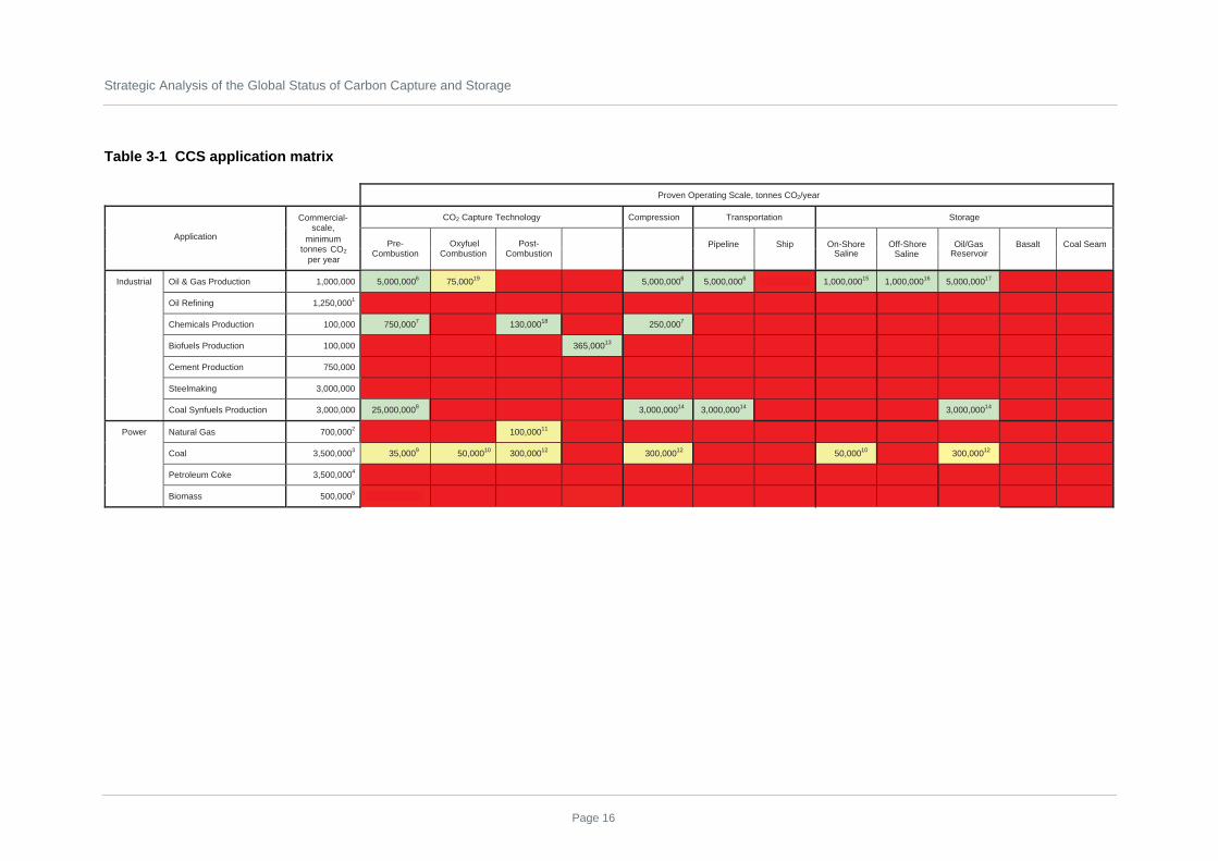
The development status of CCS across the various applicable sectors is summarised in Table 3-1. It shows the largest demonstrated annual rate of CO2 capture, compression, transport and storage that has occurred at any single location worldwide. Comparisons are also made against the minimum rate that would be required for a commercial-scale application of CCS in each applicable sector.
It should be noted that “commercial-scale” in the context of this report refers to commercial market scale. For example, for power generation applications, the basis for minimum commercial-scale is considered to be 250 megawatt electrical (MWe), 600 MWe, 600 MWe and 80 MWe for a natural gas-fired combined cycle (NGCC) plant, coal-fired power plant, integrated gasification combined cycle (IGCC) and biomass-fired Rankine cycle power plant, respectively (see Notes 2 through 5 in Table 3-1 for additional details). The “commercial-scale” term used in the First Foundation Report applies more to smaller-scale commercial projects with proven engineering viability for scale-up to full commercialisation. These smaller-scale commercial projects produce the same learnings as those from a full-scale application, but due to their smaller size, they will not be as commercially viable as the larger, commercial market-scale applications.
The shading in the table is colour-coded to represent the level of experience with CCS. Green shading means the experience matches or exceeds the minimum size needed for commercial application in that sector. Yellow shading means there has been some experience but at a scale smaller than that needed for full-scale commercial applications. Red shading means there has been no experience to date.
The data in Table 3-1 shows a mixed picture. In some sectors, such as oil and gas production, CCS has been deployed at commercial-scale sizes across the entire “chain of custody” from capture, to compression, pipeline transport and storage in various geological media. However, in a majority of the sectors, particularly in power generation, CCS usage is still an order of magnitude, or greater, away from commercial-scale operation.
Also, while pre-combustion capture has been used at commercial-scale sizes in the industrial sector, it has not been deployed at a meaningful level in the power sector. With minimal exceptions, the other two methods for CO2 capture (ie, post-combustion and oxy-combustion) have not been widely applied in the industrial sector and are being demonstrated at less than a tenth of commercial-scale in the power sector.
In order to facilitate widespread deployment of CCS across all applicable sectors, ideally all of the cells in Table 3-1 need to be shaded green by 2020. This will be a tall order. A more realistic goal might be to have at least one capture, one compression, one transport and two storage cells shaded green for each applicable sector by 2020 and a majority of the other cells shaded yellow. However, the order in which these CCS applications are demonstrated is important to achieve the desired outcomes. For example, the ability to securely sequester CO2 in commercial-scale quantities is a potential “single point of failure” in the entire CCS concept. If there is no place to store the CO2, there is little point in demonstrating the ability to capture and transport it in large quantities.
Strategic Analysis of the Global Status of Carbon Capture and Storage
Page 16
Table 3-1 CCS application matrix
Proven Operating Scale, tonnes CO2/year
Application
Commercial-scale,
CO2 egarotS noitatropsnarT noisserpmoC ygolonhceT erutpaC
minimum tonnes per year
Pre-Combustion
OxyfuelCombustion
Post-Combustion
Pipeline Ship On-Shore Off-Shore Oil/Gas Basalt Coal Seam
Industrial Oil & Gas Production 75,00019 5,000,0006 5,000,0006 1,000,00015 1,000,00016 5,000,00017
000,052,1 gninifeR liO 1
Chemicals Production 100,000 750,0007 130,00018 250,0007
Biofuels Production 100,000 365,00013
Cement Production 750,000
000,000,3 gnikamleetS
Coal Synfuels Production 3,000,000 25,000,0008 3,000,00014 3,000,00014 3,000,00014
000,007 saG larutaN rewoP 2 100,00011
000,005,3 laoC 3 35,0009 50,00010 300,00012 300,00012 50,00010 300,00012
Petroleum Coke 3,500,0004
000,005 ssamoiB 5
1,000,000 5,000,0006
CO2 Saline Saline Reservoir

Foundation Report FourExisting Carbon Capture and Storage Research and Development Networks Around the World
Page 17
Notes on Table 3-1:
1. 1.25 million tonnes per year is typical total CO2 emissions for an oil refinery, but this is made up of many smaller sources,
not one single source.
2. Basis for minimum commercial scale is a 250 MWe NGCC emitting 360 kg CO2/MWe with annual capacity factor of 85
percent.
3. Basis for minimum commercial scale is a 600 MWe coal-fired power plant emitting 800 kg CO2/MWe with annual capacity
factor of 85 percent.
4. Basis for minimum commercial scale is a 600 MWe IGCC power plant emitting 800 kg CO2/MWe with annual capacity factor
of 85 percent.
5. Basis for minimum commercial scale is an 80 MWe biomass-fired Rankine cycle power plant emitting 880 kg CO2/MWe with
annual capacity factor of 85 percent.
6. ExxonMobil natural gas processing plant in La Barge, Wyoming, United States of America (US).
7. Coffeyville Resources coal-to-urea manufacturing facility in Kansas, US.
8. Sasol coal-to-transportation fuels refinery complex in Secunda, Republic of South Africa (RSA).
9. Elcogas IGCC pre-combustion capture slipstream unit in Puertollano, Spain.
10. Vattenfall 30 Megawatt thermal (MWth) oxy-combustion pilot plant in Schwarze Pumpe, Germany and CO2 Sink/Ketzin
injection project in Germany.
11. FPL Bellingham NGCC in Massachusetts, US (no longer operating), a natural gas-fired power plant at Sumitomo
Chemical’s facility in Chiba, Japan is currently capturing approximately 55,000 tonnes per year of food grade CO2.
12. Carbon Dioxide Technology Corp and Lubbock Power & Light 2x50 MWe coal-fired power plant and enhanced oil recovery
(EOR) project in Texas, US (no longer operating).
13. ADM Ethanol production facility in Illinois, US. CO2 is naturally produced as a high purity stream from the fermentation
process in an ethanol manufacturing facility. Because this does not fit the definition of the three generic forms of capture (pre-,
post- and oxy-combustion), it is placed in the “other” category.
14. Dakota Gasification lignite-to-substitute natural gas (SNG) manufacturing facility in North Dakota, US and Encana Weyburn
EOR project in Saskatchewan, Canada.
15. In Salah natural gas processing facility in Algeria.
16. Sleipner off-shore gas production facility in North Sea (Norway).
17. Multiple sites using CO2 from La Barge facility including the Rangely CO2 EOR project in Colorado, US.
18. Ruwais fertiliser production facility in Abu Dhabi, United Arab Emirates (UAE).
19. Total Lacq 30 MWth natural gas boiler for natural gas processing operation in France.
It should be acknowledged that an assessment of CCS development across its candidate applications does not portray the full story. If CCS is to be deployed around the world, the development must also move forward around the world. This is particularly true for the storage activities. While one could argue that if post-combustion capture works successfully at full-scale on a NGCC plant in Malaysia, it would be reasonable to assume it will work successfully on a similar plant in the United Kingdom (UK). One could not make a similar argument about storage in saline reservoirs in Malaysia and the UK due to significant differences in geology between the two locations. Public acceptance and regulatory issues related to CO2 transport and storage also need to be addressed in all regions around the globe. The geographic distribution of CO2 storage experiences are addressed in more detail in Section 4.2.

Strategic Analysis of the Global Status of Carbon Capture and Storage
Page 18
3.2 Trends
Based on inputs from the panel of advisors for this project, 357 organisations were identified for inclusion in the R&D Networks database. Appendix 1 presents the complete list of these organisations. This database also identifies the regions to which the organisations belong and the type of R&D coverage being performed, as shown in Figure 3-1. It should be noted that many of these networks include members that span many different regions, and in these cases, the region where the network was being administered was entered in the database.
Figure 3-1 Number of organisations per region and type of R&D coverage performed
0
50
100
150
200
Num
ber
of N
etw
orks
F 2 3 4 1 1 1 11 1 4 1 1 1 19
E 3 3 6 3 4 2 15 3 4 2 2 2 12
D 2 5 5 2 2 1 11 1 4 1 1 2 27
C 11122422
B 5161152
A 13 28 34 11 12 5 91 5 18 3 3 4 125
Africa ANZ Canada ChinaEast Asia
(ex. Japan)
East Europe
Euro AreaIndia Area
JapanMiddle East
Pacific Islands
South America
USA
F - Political Regional and Environmental IssuesE - Information SharingD - Public Awareness and UnderstandingC - EconomicsB - RegulationsA - CCS Technologies
TOTAL 24 41 58 18 18 20 9 24 32 7 7 10 209 Source: EPRI, 2009
In many cases, an organisation is involved in more than one R&D coverage area, and this is reflected in the preceding chart. For example, if one India Area organisation is involved in CCS Technologies, Regulations and Economics, this one organisation would have a “1” contribution in rows A, B and C of the chart table. However, it is clear from Figure 3-1 that most of the networks in the database are focusing their R&D efforts on CCS technologies.
Among the three main CO2 capture technologies, the data reveals that post-combustion capture R&D is the most in-depth, followed by oxy-combustion and then pre-combustion capture. In most regions, the emphasis on CO2 sequestration R&D is proportionately similar to that devoted to post-combustion capture R&D. This data is summarised in Figure 3-2.

Foundation Report FourExisting Carbon Capture and Storage Research and Development Networks Around the World
Page 19
Figure 3-2 Number of organisations researching and developing CCS technologies
0
20
40
60
80
100
120
140N
umbe
r of
Net
wor
ks
USA 5125425305
South America 2122
Pacific Islands 2122
Middle East 2122
Japan 38737
India Area 3232
Euro Area 0123828153
East Europe 21312
East Asia (ex. Japan) 4155
China 34415
Canada 01115741
ANZ 631758
Post-combustion capture Pre-combustion capture Oxyfuel combustion CO2 sequestration CO2 transport
WORLD TOTAL 136 72 94 132 65 Source: EPRI, 2009
As will be described in more detail in the subsequent discussion of R&D gaps (Section 4), a great majority of the CO2 capture R&D is focused on the power generation sector, particularly coal-fired power generation. Given the fairly sizeable contribution that cement production makes to anthropogenic CO2 emissions, a disproportionately small R&D effort is focused on CO2 capture from cement production. While there is a significant effort based in Europe focusing on CO2 capture from iron and steel production, the overall effort in this sector is disproportionately small as well.
Even within the coal power CO2 capture R&D efforts, the vast majority of the projects are focused on the early stages of R&D and have not yet reached the small pilot plant size. As will be explained in Section 4, in order to have CCS technologies deployed at full commercial-scale by 2020, it will be necessary to have capture technologies operating on realistic conditions, at least on a small pilot scale, by 2010.
Improvements in CO2 compression have only recently begun receiving attention. While the data in Table 3-1 indicate that CO2 compression has been deployed at large-scale, it is now recognised that there is potential for improving the efficiency, and perhaps the cost, of the compression equipment. In addition, application of CCS to sectors outside of oil and gas production will bring new challenges in terms of potential co-constituents in the CO2 stream as well as different operating pressures and variable flow rates. Surprisingly, only one organisation was identified that was conducting research into the thermodynamic properties of CO2 in and near the supercritical region. As will be discussed in Sections 4.3 and 4.4, understanding these properties is a key gap in the current knowledge for designing CO2 compressors and pipelines.
The R&D efforts for CO2 transportation are modest compared to those for capture or storage. This is due in part to the fairly mature status of CO2 transportation. Long distance CO2 pipelines have been

Strategic Analysis of the Global Status of Carbon Capture and Storage
Page 20
operating in North America since the 1970s to support EOR projects. However, the scale of CO2 transportation that will be required with widespread deployment of CCS is two or three orders of magnitude greater than what is currently in place. The small R&D efforts that are taking place appear to be exclusively focused on pipelines as opposed to ocean tankers, road or rail transport. Some research is taking place to examine the optimum way to develop regional CO2 pipeline systems, and an R&D network based in Europe has started identifying key CO2 pipeline R&D needs, but as described in Section 4.2.3, more effort is needed.
CO2 storage research is currently trending away from deep ocean storage and processes that require the CO2 to be reacted with other materials (eg, mineralisation). Focus has shifted to deep geological storage in saline formations as well as alternative geological storage options such as oil and gas reservoirs, unmineable coal seams and basalt formations. Ocean storage is losing favour due to concerns about the impact on sea life, and processes that require the CO2 to be reacted with additional materials are challenged, among others, by the enormous magnitude of reactants that would be needed for widespread deployment. For example, lime is one of the most produced chemicals in the world in terms of tonnes per year, but global lime production is on the order of only 20 million tonnes per year. If each mole of lime reacted with one mole of CO2, current global production levels would only be sufficient to bind 16 million tonnes of CO2 per year – less than the annual CO2 production from five commercial-scale coal-fired power plants. There is, however, increased focus on biological fixation mechanisms such as the production of algae. The latter has increased attention because the algae could potentially be converted into a biofuel and therefore would not be a “throw away” product. However, many challenges to the widespread deployment of algae production exist; not the least of which is the large land requirement. The current state-of-the-art would require approximately 20 hectares (40 acres) per MWe to capture the CO2 from a coal-fired power plant. Thus, a commercial-scale coal-fired power plant (600 MWe) would require 12,000 hectares for the algae production system. Some research work is focused on finding more efficient algae production routes, but a majority of the algae R&D seems focused on scaling up the current state-of-the-art and finding efficient routes to convert the algae into useful products.
Geological storage R&D is focused on conducting tests in various geological strata and on developing and proving techniques for monitoring CO2 in those strata. Clearly this effort must continue in earnest if CCS is to begin commercial-scale deployment in 2020. However, as explained in more detail in Section 4.2.3, insufficient R&D effort is focused on decreasing the cost of finding, developing and operating geological storage sites for CO2.
Beyond R&D on CCS technologies, Figure 3-1 shows that public awareness and understanding has the most number of organisations involved in non-technical R&D efforts. This trend is expected to grow as CCS projects become larger and more prevalent. As discussed further in this report, some CO2 storage projects have been postponed, moved or cancelled due to opposition from the local public. Such opposition will not be swayed without greater focus on public awareness and understanding.
Based on the numbers in Figure 3-1, there appears to be fewer organisations involved in formal research on economics, regulations, and political and environmental issues, but it should be recognised that several nations and supra-national organisations (eg, the European Union (EU)) are actively examining public policy options on these topics, so the database may be under-representing the true level of effort going on in these areas.
In assessing the degree of networking among the organisations in the database, it was determined that roughly 55 percent of the entries were single-entity “networks” while 45 percent were formal, multi-

Foundation Report FourExisting Carbon Capture and Storage Research and Development Networks Around the World
Page 21
entity collaborations. The median value of collaborating organisations in the multi-entity networks was three, and only 16 of the networks had at least 10 organisations involved. Consequently it appears that most of the CCS R&D is being conducted by independent entities or small collaborations of two or three organisations. While it was pointed out in the Introduction section of this report that independent R&D is often the source of technology breakthroughs, it is also the case that technology development can be accelerated by learning from the successes and failures of others. Therefore, it is recommended that the Global CCS Institute investigate options for fostering greater networking among the many entities that are conducting CCS R&D worldwide without imposing a structure that could stifle independent creativity.
It should be noted that having duplicative R&D efforts going on in multiple regions and in some cases by multiple organisations in the same region is not necessarily a waste of R&D resources. Simultaneous research by more than one party can serve to provide independent verification of results. It can also spur competition that can speed up timelines and lead to a market with multiple suppliers of commercial technology, which subsequently drives down prices.

Strategic Analysis of the Global Status of Carbon Capture and Storage
Page 22
4. Gaps in R&D
4.1 Background for the R&D gap analysis
One of the primary goals of this report is to identify vital development pathways that should be resourced or expanded to accelerate the deployment of CCS technologies. Various international organisations have concluded that at least 20 large-scale (greater than 1 million tonnes per year) CCS projects are needed in different geological storage media around the world to pave the way for widespread commercial CCS deployment. For example, at the 2008 meeting in Hokkaido, Japan, the Group of Eight (G8) leaders declared:
"we strongly support the launching of 20 large-scale CCS demonstration projects globally by 2010, taking into account various national circumstances, with a view to beginning broad deployment of CCS by 2020."
The IEA has proposed that the criteria for “large-scale” should be at least 1 million tonnes of CO2 storage per year, and the projects must include CO2 capture, transport and storage in order to qualify as one of the 20 CCS demonstrations (OECD/IEA 2009).
CCS demonstrations are needed to verify operational reliability, actual initial capital investment and operating costs in different applications, which cover various fuel types, carbon capture technologies and geological storage media. Demonstrations will need to be conducted on a large-scale with fully-integrated operations after scale-up from smaller-sized pilot plant, slipstream units or storage demonstrations. Experiences gained from operating these initial demonstration plants can be used to optimise the overall integrated design of the plant, including start-up and shutdown procedures and control systems for steady-state and transient operations integrated with CO2 transport and storage capabilities.
Momentum is starting to build in response to the G8 leaders’ call. For example, the EU has targeted 1.1 billion Euros to support up to seven large-scale CCS demonstrations as part of its European Energy Program for Recovery. Similarly, the US Federal Government has allocated US$1 billion for its FutureGen IGCC project and another US$1.4 billion for its Clean Coal Power Initiative. Meanwhile, the Canadian province of Alberta announced three CCS projects that will share C$2 billion in support, and the Australian Federal Government recently announced the formation of a AU$2 billion CCS Flagships Program that is targeted to support two to four CCS demonstrations. However, none of these projects have progressed to even the detailed engineering stage, and all will face a series of hurdles before they can begin storing CO2 underground. More information on the status of CCS demonstrations can be found in the First Foundation Report of the Global CCS Institute Strategic Analysis.
In addition to large-scale demonstrations, significant improvements are needed in the cost of implementing CCS. One should not have to rely on endless government subsidies to make CCS economically attractive. If CCS is to become widely deployed globally, technology improvements must lead to decreases in the cost of implementing CCS over time to less than the environmental cost of emitting CO2.
This section identifies R&D gaps that need to be filled in order to pave the way for the proposed large-scale demonstrations as well as those needed to achieve reductions in cost. However, before specific gaps are identified, it is important to review the normal development path for industrial technology.

Foundation Report FourExisting Carbon Capture and Storage Research and Development Networks Around the World
Page 23
Experiences with developing other power generation and emission control technology have shown that new technologies must progress through nine levels of technical readiness (Mankins 1995), or Technical Readiness Levels (TRLs) before they reach “commercial deployment.” The nine TRLs are listed in Table 4-1.
The achievement of a given TRL will inform process developers and customers on the advice necessary to commit resources required to achieve the next level of readiness. An achievement of TRL-9 indicates that the technology can be deployed with risks that are comparable to those undertaken on other “commercial” technologies that are commonly deployed. Only customers who are able to take on higher risks will be suitable participants in efforts to achieve the TRLs up to and including TRL-9.
In the mid-20th century, coal-fired power plants had no controls for sulphur dioxide (SO2), nitrogen oxides (NOx) or mercury emissions. Throughout the last 50 years, various technologies to control these pollutants have progressed from about TRL-4 to multiple commercial installations. This experience indicates that the achievement of TRL-9 can take approximately 20 years. This long development time is largely dictated by design and construction activities associated with the field deployment of pilot plants (to achieve TRL-7), commercial pilot plants (to achieve TRL-8) and the first full-scale, commercial installation (TRL-9).
Table 4-1 The nine technical readiness levels for technology deployment
TRL-9 Full-Scale Commercial Deployment
TRL-8 Sub-Scale Commercial Demonstration Plant
TRL-7 Pilot Plant
TRL-6 Component Prototype Demonstration
TRL-5 Component Prototype Development
TRL-4 Laboratory Component Testing
TRL-3 Analytical, “Proof of Concept”
TRL-2 Application Formulated
TRL-1 Basic Principles Observed
To a certain extent, the overall development times may be shortened by committing resources for a pilot plant, demonstration or full-scale deployment concurrent with activities designed to achieve TRLs lower on the ladder. Commercial or other considerations may recommend such a “fast-track” approach. It is often the case, however, that the effort to achieve a TRL lower on the ladder will reveal process design, operation or maintenance requirements that were not apparent at the beginning. Indeed, this is one of the major motivations for undertaking an orderly approach to technology development; it is likely to be less expensive in cost and time to implement remedies for such uncovered requirements at a modest scale than at a larger scale.

Strategic Analysis of the Global Status of Carbon Capture and Storage
Page 24
Experience has shown that passing over any of the development steps up the TRL ladder will increase the likelihood of failing to achieve the targeted TRL and may eventually necessitate returning to the skipped TRL step before progressing further.
The time required to design, deploy and operate facilities to achieve specific TRLs increases significantly as the TRL increases. If multiple CCS demonstrations with improved technologies are to be achieved at large-scale (ie, TRL-9) by 2020 to proceed with commercial deployment, then many technologies need to be approaching the pilot plant stage (TRL-7) today. Figure 4-1 shows an example of an aggressive development schedule for a capture process from TRL-1 through TRL-8. TRL-9 would start with design and permitting in 2013 (two years), construction in 2015 (three years) and operation in 2018 (two years). This aggressive schedule would need to be followed in order to have two years of operation at full-scale by 2020. Those two years of operation (assuming successful deployment) should be sufficient to convince a buyer to include the process in a project that begins its design from 2020.
Figure 4-1 Timescale for capture process development
2006 2007 2008 2009 2010 2011 2012 2013 2014 2015 2016 2017 2018 2019 2020
TRL 1
TRL 2
TRL 3
TRL 4
TRL 5
TRL 6
TRL 7
TRL 8
TRL 9
TRL
Year
DesignConstructionOperations
Source: EPRI, 2009
Unfortunately, a recent review of post-combustion capture technologies (see Section 4.5) has shown that only a few new technologies have reached the TRL-7 (pilot plant stage).
R&D of technology can be thought of as water flowing through a leaky pipe (see Figure 4-2). Many ideas go into one end of the pipe, but few reach the outlet (commercial deployment) because of challenges encountered along the way. If society wishes to have multiple new technologies for CCS at the commercial deployment stage in 2020, it needs funding at the early TRL stages today. This is the genesis of a more serious type of R&D gap than the one described above. In the case of post-

Foundation Report FourExisting Carbon Capture and Storage Research and Development Networks Around the World
Page 25
combustion capture, there are well over 50, and perhaps more than 100, technologies in the “pipeline”, but unfortunately only a few have reached TRL-7. Accelerating the development of the technologies in the pipeline should be sufficient to ensure that several reach TRL-9 by 2020. However, in some areas such as developing lower cost oxygen production, there are only a handful of new technologies anywhere in the R&D pipeline. In that case, accelerating the identified technologies may not be sufficient as all of them might “leak out” of the pipeline before they reach TRL-9. So, not only do the identified technologies need to be accelerated, the inlet of the pipeline also needs to be primed with additional new concepts, and those concepts need to be quickly nurtured through the first four or five TRLs.
In each of the following sub-sections, the status of technology or policy/regulatory development is assessed and compared to the level of R&D activity taking place in that area. Any gaps in the R&D are then identified.
Figure 4-2 Technology development and leaky pipe analogy
Source: EPRI, 2009
4.2 Proof of large-scale sequestration
Geological sequestration of CO2 is currently being demonstrated in several projects around the world. Four projects—Statoil’s Sleipner Saline Aquifer CO2 Storage project in the North Sea off Norway; the Snøhvit Liquified Natural Gas (LNG) project in Norway; the Weyburn Project in Saskatchewan, Canada; and the In Salah Project in Algeria—together sequester about 6 million tonnes of CO2 per year, which collectively approaches the output of a typical 1000 Megawatt (MW) coal-fired power plant. With over 25 cumulative operating years of experience, these projects have thus far demonstrated that CO2 storage in deep geological formations can be carried out safely and reliably.

Strategic Analysis of the Global Status of Carbon Capture and Storage
Page 26
Statoil estimates that Norwegian GHG emissions would have risen incrementally by three percent if the CO2 from the Sleipner project had been vented rather than sequestered.
Table 4-2 lists a selection of current and planned CO2 storage projects as of early 2009, including those involving EOR.
Table 4-2 Select existing and planned CO2 storage projects as of early 2009
Amount Injected By Project CO2 Source Country
Start of Injection 2006 2010 2015
Rangely Gas Processing US 1986 22 MT 25 MT 29 MT
Sleipner Gas Processing Norway 1996 9 MT 12 MT 17 MT
Weyburn Coal Canada 2000 5 MT 15 MT 26 MT
In Salah Gas Processing Algeria 2004 2 MT 7 MT 12 MT
Midale Coal Canada 2005 1 MT 3 MT 5 MT
Ketzin/CO2STORE Not Applicable Germany 2007 50 kT 50 kT
Otway Natural Australia 2007 100 kT 100 kT
Snøhvit Gas Processing Norway 2008 2 MT 5 MT
Gorgon Gas Processing Australia 2010 12 MT
TOTALS 39 MT 64 MT 106 MT
Note: kT = kilotonnes and MT = megatonnes
4.2.1 Enhanced Oil Recovery
Experiences relevant to CCS can be obtained from the oil industry, where CO2 injection technology and modelling of its sub-surface behaviour have a proven track record. EOR has been conducted successfully for 35 years in the US Permian Basin fields of west Texas and Oklahoma. Regulatory oversight and community acceptance of injection operations for EOR seem well-established, and currently approximately 48 million tonnes of CO2 are used for EOR operations annually in North America (Steele 2008).
Although the purpose of EOR is not to sequester CO2 per se, in practice it does amount to geological storage. Since the start of its use 35 years ago, CO2 had been geologically stored after completion of the EOR, therefore some (about 50 percent if totally depressurised) could be re-used in potential nearby EOR developments at a later date. Very little CO2 was ever returned to the atmosphere, as its production was the biggest operating cost of EOR. The EOR field operator, therefore, had a strong incentive to prevent the CO2 from leaking or venting.
The Weyburn EOR project in Saskatchewan, Canada uses captured and compressed CO2 from the Dakota Gasification Company’s Great Plains synfuels plant near Beulah, North Dakota. The CO2 is transported via a 300 kilometre (km) pipeline constructed of standard carbon steel. Over the life of the project, the net CO2 storage is estimated at 26 million tonnes, while an additional 155 million barrels of

Foundation Report FourExisting Carbon Capture and Storage Research and Development Networks Around the World
Page 27
oil (bbl) will be produced. In addition to the Weyburn site, CO2 produced from the Dakota Gasification plant is also being injected into the nearby Midale field, also in Canada, where an estimated 8.5 million tonnes will be stored while producing an additional 67 million bbl (PTRC 2009).
It should be noted that more than half of the CO2 that has been used for EOR to date has come from naturally occurring reservoirs of CO2. While these reservoirs testify to the potential for long-term storage of CO2 in the proper location, the transfer of CO2 from one underground location to another does not contribute to a reduction in atmospheric CO2 concentrations. Nevertheless, each year in North America, approximately 19.5 million tonnes of anthropogenic CO2 is used for EOR projects.
Anthropogenic sources of CO2 are generally easy-to-utilise: high-purity CO2 vents from natural gas sweetening (removal of CO2 and hydrogen sulphide (H2S) from raw natural gas), ammonia plants (involving carbon monoxide (CO) shift and CO2 separation from synthesis gas (syngas)) and the commercial coal-to-SNG Dakota Gasification plant. It should be noted that there are an increasing number of natural gas fields where the raw natural gas is high in CO2 content.
EOR is a large commercial CCS application where the CO2 has a value. However, that value is perhaps only 25 to 50 percent of the CO2 capture costs for a coal-fired power plant that implements CCS. Industrial gasification plants generally have CO2 capture costs closer to the CO2 price in EOR simply because they make large, pure CO2 vents regardless of the CO2 mitigation issue (Simbeck 2009).
Typical supercritical CO2 delivered for EOR is about US$1 per 1,000 standard cubic feet (scf) or almost US$19/tonne CO2 and utilised at a rate of about 0.31 to 0.47 tonne/ bbl (6,000 to 9,000 scf/bbl) oil produced. It is increasingly common to link the CO2 price to the oil price due to the large fluctuations in oil prices over the last few years. It is useful to know that at about 0.43 tonne (8,160 scf) of CO2 consumed and stored per barrel of EOR, the produced oil is CO2 neutral. An increase in EOR operations avoids or replaces conventional oil use that does not have this large CO2 storage advantage.
Placing a value on avoiding CO2 emissions would undoubtedly reduce the CO2 price paid for EOR but would also greatly increase the amount of CO2 that could economically be used per barrel of oil produced. Based on an analysis for the US DOE on the future potential of CO2 use in expanded EOR, this could reach approximately 9 percent of US anthropogenic CO2 emissions and increase US domestic oil production (via EOR) from about 225,000 bbl per day to around 3 million bbl per day, assuming high oil prices (Simbeck 2006; Kuuskraa & Koperna 2005).
4.2.2 Gaps in proof of large-scale sequestration
While the experiences gained from existing large-scale CO2 storage projects provide confidence that geological storage is possible, it does not by itself open the door for widespread deployment of CCS. As shown in Table 4-3, there are still a large number of gaps in the demonstration of large-scale CO2 storage in various underground media around the world. For example, while storage of CO2 in North American oil reservoirs is clearly well-demonstrated, not all sources of CO2 in North America are located near an oil field (and not all oil fields are amenable to using CO2 for EOR), nor is the capacity of the suitable oil reservoirs sufficient to store all the CO2 which could potentially be captured by 2050. Therefore, other options for geological storage need to be proven. In addition, due to regional variations in geology, it is important to conduct similar tests in multiple regions around the world. Projects in multiple locations also help build public confidence and acceptance in a wider-spread fashion.

Strategic Analysis of the Global Status of Carbon Capture and Storage
Page 28
Table 4-3 Storage matrix
Current annual storage rate, tonnes of CO2
Region Onshore saline
Offshore saline
Oil/gas reservoir Basalt Coal seam
Americas 65,000 48,000,000 900 70,000
Europe 125,000 1,000,000 700,000
Africa 1,300,000
Asia 10,0001
ANZ 65,000
Note 1: 10,000 tonne per year test injection was conducted near Nagaoka, Japan in 2004, but injection ended in 2004.
In addition to the specific technology gaps identified in the following sub-section, it is clear from the storage matrix in Table 4-3 that even before large-scale tests can begin, smaller scale storage tests are needed in many regions of the world in a variety of storage media. These tests will help clarify regulatory issues and increase public acceptance, which might otherwise stall or delay larger tests. They will also provide information on the storage characteristics of the media, which will be needed to design the storage systems for larger demonstrations in the same locations and also develop the local expertise that will be needed to execute and monitor these larger projects.
4.2.3 Storage technology R&D gaps
The International Energy Agency Greenhouse Gas R&D Program (IEA GHG), the organisers of the 9th International Conference on Greenhouse Gas Control Technologies (GHGT-9), which took place in November 2008, have produced a summary of the results presented at the conference as well as key issues that still need to be addressed. The key issues for storage include the following:
• there is a need for greater understanding of saline water displacement and pressurisation in saline aquifer formations;
• currently, there are two methodologies for estimating storage capacity, both of which deliver volumetric assessments that can be compared easily. However, the resulting estimates are ‘theoretical’ and do not allow for a variety of technical and economic factors that could reduce the actual available capacity. A key challenge is to supplement these high-level theoretical storage capacity estimates with more realistic site- or region-specific capacity assessment, by taking into account such factors as over-pressurisation and brine displacement;
• researchers need to understand better, and to quantify, the trapping mechanisms that determine the long-term fate of injected CO2; and
• risks associated with potential leakage from storage formations need to be quantified for regulatory and public assurance. Such risks could include potential impacts on human health, ecosystems and shallow reservoirs suitable for potable supply. Induced seismicity constitutes another potential hazard but its potential impact needs to be assessed.
IEA GHG also noted that the GHGT-9 highlighted some important novel concepts for geological storage including surface dissolution in saline formation brines, storage in sea bed sediments, hydrate

Foundation Report FourExisting Carbon Capture and Storage Research and Development Networks Around the World
Page 29
deposits, and deep sea basaltic formations. These alternative options showed great early potential as future storage options and warranted continued research.
In March 2009, EPRI sponsored a workshop on CO2 Transport and Storage Modelling (Rhudy 2009). The purpose of the workshop was to determine what R&D was needed to improve models for predicting the cost of CO2 transport and storage. In addition to examining the techniques for modelling, the participants also identified technologies that could potentially decrease the cost of transportation and storage. Key recommendations related to improving the ability to predict storage costs and to decrease the cost of storing CO2 are listed below:
• Document the experiences of the natural gas storage industry and the natural CO2 production and transportation industry to gather failure incident probability and risk data as well as remediation cost data. Little reliable information exists on the likelihood of minor or major leakage of CO2 or wellbore failure incidents. Also, little first-hand information exists on the costs of remediating these incidents, which limits the reliability of current risk assessment models and methodologies. However, worldwide there are currently over 600 underground storage facilities for natural gas, and more than 60 of these use aquifers. In the US alone, the amount of natural gas injected into underground storage sites each year is equal in volume to storing 160 million tonnes of supercritical CO2. This experience could provide useful analogues and lessons learned for CO2 storage;
• Alternative storage designs and well placements, including the use of horizontal injection wells should be examined and tested. Current guidelines for CO2 storage capacity, which are drawn from experience with traditional geological storage facilities, assume that only one to four percent of the theoretical storage capacity in a saline formation can be accessed and used. EPRI believes these alternative techniques may allow the useable storage capacity to increase to 10 to 20 percent of theoretical capacity; and
• Well simulation techniques that have been tested by the gas storage industry should also be examined for CO2 storage. Many of the potential CO2 storage reservoirs are low in permeability, which limits the volume of CO2 that can be injected through a single well. This leads to the need to drill many more CO2 injection wells, thereby increasing the cost of implementing storage and can also create possible pressure interference, further reducing CO2 injectivity. Well simulation techniques could allow more CO2 to be injected from an individual well. In addition, alternative well spacing designs should be evaluated for their ability to preclude pressure interferences.

Strategic Analysis of the Global Status of Carbon Capture and Storage
Page 30
Key finding:
In addition to the R&D requirements, techniques for reducing the costs of characterising storage sites are critical. Schlumberger has estimated that it could cost approximately US$50 million to characterise a site where no seismic data currently exists (Peters 2009). This is typical of many sites outside of oil and gas producing regions, and it presents a major hurdle for commercial ventures that are considering CCS. Not only is it a significant up-front cost, but a thorough characterisation that would include seismic scans, drilling of test wells to determine injectivity, and the development a commercial-scale injection and monitoring system design could take up to three years to complete, which may conclude the site as unsuitable for storage. At this point, few commercial entities will want to take this financial risk and, instead, will delay the decision to implement a CCS project.
Duke Energy’s recent request from the Indiana Utility Regulatory Commission (IURC) for US$121 million for detailed characterisation of storage sites, including multiple wells, around Edwardsport is one example of the magnitudes developers are facing. The three-year site characterisation effort would result in an average customer rate increase of about 1 percent, which would be phased in between 2010 and 2013. If the site characterisation study is successful, Duke Energy will ask the IURC for permission to implement CCS.
It is clear that lower cost approaches that allow potential storage sites to be quickly screened on a “go, no go” basis are needed in order to foster the widespread deployment of CCS.
Key finding:
There is also a need for the development of a business structure that would facilitate the screening and certification of geological storage sites. This is so that industries considering installation of CO2 capture systems know with certainty that there will be a location to store the captured CO2 at a known cost. For example, the Clean Air Task Force has proposed the concept of managing geological carbon storage through a regulated public utility. The role of such a public utility would be to develop, operate and manage all geological CO2 storage sites within a given geographic area, and it would recover its costs via fees regulated by a government utility commission similar to those used to regulate electric utilities (Waltzer 2008). This would allow the costs of locating and developing potential storage sites to be spread across all future users rather than placed onto the already considerable financial burdens of first movers. More research into appropriate business structures will facilitate a wider and more rapid implementation of geological storage.
Earlier this year, the Alberta Carbon Capture and Storage Development Council issued a report on ways to accelerate the deployment of CCS in the Canadian province of Alberta. Among the report’s recommendations for additional R&D was a suggestion that “additional technology funding should be directed to testing of CO2 EOR in immiscible light and heavy oil pools, which could increase the size of the EOR market by 50 percent.” This is in line with similar recommendations in an earlier US DOE report, which indicated that “game changer” technologies based on scientifically possible advances

Foundation Report FourExisting Carbon Capture and Storage Research and Development Networks Around the World
Page 31
could significantly increase the amount of oil recovered and CO2 stored in US oil fields (Kuuskraa 2007). These additional tests could help verify the energy penalty associated with these processes for oil recovery and would enhance public acceptance. A review of existing CCS R&D did not reveal any significant activity in this area, and therefore, it is identified here as a gap.
Key finding:
A final R&D gap is the investigation of the impacts of CO2 impurities. Since CO2 used for EOR does not typically have more than a few ppm of oxygen (O2), there is no data to show what would happen if CO2 from an oxy-combustion process with perhaps 200 ppm of O2 was injected into a reservoir. Would the O2 promote reactions with the sub-surface rock that could affect the permeability of the reservoir? Would it promote growth of microbes in sub-surface water that might foul the injection ports? Similarly, if a storage site accepted CO2 from both pre-combustion capture and post-combustion capture sources, there is a possibility that both H2S and SO2 would be present. Would these react in the formation via the Claus reaction and produce sulphur, and would that impact permeability? The entire topic of sub-surface chemistry impacts of CO2 impurities is a field that appears to be ripe for investigation.
4.3 CO2 transportation gaps
Mapping of the distribution network for potentially suitable CO2 storage formations across the globe shows that some areas have ample storage capacity while others appear to have little or none. Thus, implementing CO2 capture at many sources may require long-range transportation by either pipelines or ships to suitable injection locations, possibly in other countries.
Transportation by pipeline does not represent a major technical hurdle as demonstrated by the existing long-distance CO2 pipelines being used commercially in oilfield EOR applications in North America. In the US, the Department of Transportation’s Pipeline and Hazardous Materials Safety Administration (PHMSA) regulates the handling and transportation of supercritical CO2. PHMSA reports that 65 percent of US CO2 assets were installed more than 20 years ago, and only 12 percent have been installed since 2000. They report only 36 CO2 asset failures, with only four incidents related to material corrosion. It is the position of PHMSA that CO2 pipelines are at least as safe as natural gas pipelines (Steele 2008).
While the successful experience in North America with CO2 pipelines should provide confidence that it is feasible to transport large volumes of CO2 over long distances, gathering CO2 from a number of sources, whereby each may have different impurities in the CO2 stream, will raise challenges not currently faced by the existing CO2 pipelines. Even relatively small percentages of impurities in CO2 streams can impact the phase behaviour of the mixture. A pipeline that may operate in the supercritical phase with high purity CO2 produced from a natural reservoir could experience two-phase flow and/or significantly higher pressure drops if a less pure CO2 mixture from a power plant or industrial source is transported through it.

Strategic Analysis of the Global Status of Carbon Capture and Storage
Page 32
While it is technically feasible to clean the CO2 stream to a high purity, this could add significant costs to the capture system, which would impede the goal of lowering costs to foster wider deployment. More study is needed to determine the cost and performance trade-offs between accepting more impurities in a pipeline CO2 stream, upgrading pipeline materials and increasing the number of compressor booster stations against installing CO2 polishing systems at the capture plant and using carbon steel pipelines. As a first step in this effort, improved equations of state for mixtures of supercritical CO2 and other compounds are needed for hydraulic simulations and flow validation.
Key finding:
EPRI, Newcastle University in the UK (Race 2009) and the CO2PIPETRANS collaboratively organised by Det Norkse Veritas (DNV) (Det Norkse Veritas 2009) have each recently published a list of R&D needs related to CO2 pipeline transportation. A merged version of their recommendations is listed below:
• Additional research, development and demonstration (RD&D) is needed to better define the thermodynamic properties of CO2 and CO2 mixtures at supercritical conditions. Currently available equations of state models to predict the properties of supercritical CO2 with impurities (eg, Argon (Ar), nitrogen (N2), O2, CO, ammonia (NH3), and H2S), at conditions near the critical point are not reliable for precise design. Improvements with these models could facilitate in researching alternative, less power- or capital-intensive methods to produce supercritical CO2 and in optimising the integration of CO2 capture and compression systems with the pipeline system;
• Further the investigation of the effects of impurities on water solubility in supercritical CO2;
• Identify, document, and quantify trace impurities from various new and innovative CO2 capture technologies and approaches that will potentially remain with the captured CO2;
• Further investigation is needed of the compatibility of non-steel materials (eg, elastomers/polymers for seals and gaskets) with CO2 impurities;
• Conduct more detailed material science analyses of existing CO2 pipelines and handling equipment. Confirm the integrity of the oldest CO2 pipelines and potentially update existing material corrosion rates;
• Investigate corrosion R&D to confirm the impact of impurities from newly developed CO2 capture technologies on the corrosion rates of carbon steel pipelines and to evaluate the risk of CO2 corrosion in case of an accidental intake of humidity;
• Revisit and improve existing models of pipeline fracture propagation and verify the models with full-scale crack arrest testing;
• Improve CO2 pipeline blowdown and depressurisation models and associated controls, and generate supercritical/dense phase CO2 release data for model validation. This will enable the CO2 pipeline designers to determine adequate safety zones and avoid excessive land acquisitions;

Foundation Report FourExisting Carbon Capture and Storage Research and Development Networks Around the World
Page 33
• Investigate hydrate formation to avoid operational downtime; and
• Public communication and interaction to build trust and awareness around transmission of CO2 in pipelines.
CO2PIPETRANS has estimated the cost of performing its recommended R&D to be a relatively modest sum (US$6.7 to US$7.5 million).
4.3.1 Pipeline network optimisation
As the number of projects increases, regional CO2 pipeline networks connecting multiple sources with storage sites will be needed. If an “early mover” CCS project must build a new pipeline to a storage location, the question arises: Would it be in the best interest of society to have them build a much larger pipeline than is needed for that single project so that future capture projects in the same region can use a single “trunk” pipeline? Or should capacity be expanded by adding new pipelines alongside existing ones? Some research has started examining approaches to building optimal networks (for example, the work by the Climate Change Policy Partnership of Duke University in the US), but more R&D effort on this topic is needed.
4.3.2 Ocean transport
Some regions of the world may conclude that they have little or no domestic resources that are compatible for geological storage of CO2. Other regions of the world, such as the Gulf Coast of the US, appear to have ample capacity to store CO2 produced from their domestic sources, and thus would have ability to accept CO2 imported from other regions. There is also the possibility of discovering large storage sites far offshore. Consequently, the transportation of CO2 either under (ie, pipelines) or on top (ie, ships) of oceans may eventually be needed.
Newcastle University, UK has highlighted that “offshore transport of CO2 (via pipelines) may not be economically feasible if repressurisation is required, due to the high cost involved in installing pumps and compressors in a marine environment (Seevam et al. 2008).” Consequently, for long distance ocean transport, it appears that ships will be the most viable option. However, as the CCS Application Matrix (Table 3-1) shows, there is no experience with bulk transport of CO2 in ships.
For smaller scale transport, or for injection tests of a short duration, CO2 transport via tank trucks is the most economic option. This is the way most food-grade CO2 is transported around the world. Since tank truck transportation is a well-established technology, no significant R&D needs are apparent.
4.4 R&D gaps for CO2 compression
Compared to other parts of the CCS supply chain, CO2 compression is a relatively mature technology, which has been used at the scales needed for most commercial CCS applications. Consequently, the level of R&D activity related to CO2 compression has been fairly modest. Nevertheless, there are several areas that need to be addressed to reduce the economic risks of CCS projects. There are also additional opportunities for cost reduction that are not being adequately addressed by the current, modest R&D efforts.

Strategic Analysis of the Global Status of Carbon Capture and Storage
Page 34
Many of the issues related to the impact of CO2 impurities on thermodynamic properties and materials that are important for CO2 pipelines are also relevant to the design of CO2 compression systems.
Key finding:
In addition to the CO2 transportation R&D gaps previously highlighted, EPRI has identified the need to:
• Continue the development of large-scale semi-isothermal and high-pressure-ratio adiabatic CO2 compressors in order to decrease the parasitic load of compression systems;
• Approach the aircraft and military gas turbine community and discuss the potential to design an advanced, axial-flow, high-pressure-ratio CO2 compressor. Currently there are no axial flow CO2 compressors, but such a machine would allow the recovery of high temperature heat in compressor aftercoolers, which would improve the overall efficiency of power plants integrated with CO2 capture and compression systems. The high temperature heat recovery could be used to generate additional power in the plant;
• Perform more gas properties and thermodynamic activity coefficient measurements for CO2 mixtures;
• Optimise the integration of CO2 capture/compression systems together with the plant;
• Compare and evaluate compression and early-stage liquefaction and pumping options and configurations;
• Investigate higher voltage, higher power and speed machines and drives; determine the optimal machine types, speeds, and required voltages, etc. for CO2 compressors;
• Install test coupons in existing CO2 pipelines to obtain corrosion data, then develop CO2 product specifications;
• Establish allowable levels of contaminants in CO2 pipeline and/or compressors;
• Quantify compressor heat exchanger data for plant applications including supercritical fluids; and
• Integrate utilisation of waste heat to improve cycle efficiency.
4.5 R&D gaps for CO2 capture from power generation
There are three main approaches for the capture of CO2 from fossil based plants:
• Post-combustion removal of CO2 from the flue gas;
• Combustion of the fuel with oxygen (oxy-combustion); and
• Pre-combustion removal of CO2 from natural gas or syngas (from fuel gasification or reforming of natural gas).

Foundation Report FourExisting Carbon Capture and Storage Research and Development Networks Around the World
Page 35
4.5.1 Post-combustion removal of CO2
Most post-combustion CO2 capture processes envisioned for power plant boilers draw upon commercial experience with absorption and separation using amine solvents. This is currently done at a much smaller scale (up to 20 MW equivalent) in the food, beverage and chemical industries, and in three applications of CO2 capture from slipstreams of exhaust gas from circulating fluidised bed combustion (CFBC) units. These processes can also be used for the recovery of CO2 from other commercial combustion flue gases such as from the fired heating of natural gas reformers as well as the fired heaters in petroleum refineries, cement plants and industrial boilers and heaters.
These processes contact flue gas with an amine solvent in an absorber column where the CO2 chemically reacts with the solvent. The CO2-rich liquid mixture passes to a stripper column where it is heated, releasing the CO2, and the “regenerated” solvent is re-circulated back to the absorber column. The released CO2 may be processed further before compression to a supercritical state for transportation to a storage location. This process is shown in Figure 4-3.
After drying, the CO2 released from the regenerator is relatively pure. However, successful CO2 removal requires very low levels of SO2, NOx and controlled amounts of O2 in the flue gas entering the CO2 absorber, as these species also react with the solvent. Thus, high-efficiency SO2 and NOx control systems are essential to minimising solvent consumption costs for post-combustion CO2 capture.
The addition of current commercial amine solvent separation technologies to coal-fired pulverised coal (PC) units would impose high capital and operating costs and require steam and power inputs that would substantially reduce the net plant output by about 30 percent. Extensive RD&D is in progress to improve the solvent and system designs for power boiler applications as well as to develop better solvents with greater absorption capacity, less energy demand for regeneration, greater ability to accommodate flue gas contaminants and reduced impact of solvent and solvent degradation products when released into the environment.
4.5.2 Amine-based solvent technologies
The two leading manufacturers of post-combustion CO2 capture technology, Fluor and Mitsubishi Heavy Industries (MHI), are working to meet the requirements of large-scale power plant applications by increasing the performance of their solvents and decreasing the amount of thermal energy required to regenerate them.
Fluor’s Econamine FG process uses a 30 percent aqueous solution of monoethanolamine (MEA) solvent with proprietary additives. Econamine is deployed at some 20 plants supplying CO2 to the chemical and food industries and for EOR. However, none of these units process coal-derived flue gas.

Strategic Analysis of the Global Status of Carbon Capture and Storage
Page 36
Figure 4-3 Generic absorption/stripping process for flue gas removal of CO2
Source: WorleyParsons, 2009
Note: CW = Cooling water.MHI has successfully used an amine solvent, designated KS-1, at several large-scale commercial plants for fertiliser and heavy oil production. The first testing of KS-1 on coal-generated flue gas is under way at a 10 tonne per day CO2 pilot at JPower’s Matsushima plant in Nagasaki, Japan.
Three other suppliers have completed extensive pilot plant programs and are submitting proposals in response to solicitations for commercial projects. They are:
• Aker Clean Carbon – an earlier version of the process is used to capture CO2 on the Sleipner project;
• Cansolv – the process uses two solvents to simultaneously remove SO2 and CO2; and
• HTC Purenergy – the process includes a control system to optimise heat utilisation.
Along with modifications to the chemical properties of sorbents, research is also addressing the physical structure and scale-up of the absorber and regenerator equipment, examining membrane contactors to improve gas-liquid contact and/or heat transfer, optimising thermal integration with steam turbine and balance-of-plant systems and the environmental impact of solvent and solvent degradation products.
POTENTIAL ALTERNATIVES TO AMINE-BASED SOLVENT TECHNOLOGIES
Extensive research is being carried out to identify new processes and liquid solvents for CO2 capture that offer economic advantages and are suitable for scale-up and demonstration. Some notable examples of this development work include post-combustion CO2 capture using a chilled aqueous ammonium carbonate as the solvent, currently under development and testing by Alstom and a consortium of EPRI members. CO2 is captured in an absorber at low temperature and atmospheric pressure, forming ammonium bicarbonate, which then is regenerated at increased temperature and high pressure to drive off a concentrated stream of CO2. Although still to be confirmed, it is projected

Foundation Report FourExisting Carbon Capture and Storage Research and Development Networks Around the World
Page 37
that the heat of regeneration will be significantly lower than that of amine systems. Further, because the CO2 is released at pressure, less energy is required for the compression stage.
Alstom and the EPRI consortium have constructed a 1.7 MW pilot unit connected to a flue gas slipstream at We Energies’ Pleasant Prairie Power Plant, and testing has commenced. A 20 MW scale-up is planned at American Electric Power’s (AEP) Mountaineer power plant in West Virginia, with AEP potentially hosting a 200 MW scale-up demonstration at its Northeastern station in Oklahoma.
Also in development is an ammonia-based process (ECO2) that is being tested by Powerspan at 1 MW scale at FirstEnergy’s R.E. Burger plant in Ohio. Basin Electric plans to test a 120 MW scale-up at its Antelope Valley station in North Dakota.
Ionic liquids, a class of organic compounds, show promise for post-combustion CO2 capture as they can be formulated to have high selectivity for CO2 relative to N2 and O2. Unlike amines, they do not react with CO2 but form weak ionic bonds that result in a relatively low heat of regeneration. The US DOE - National Energy Technology Laboratory (DOE-NETL) is currently funding R&D in this area at the University of Notre Dame.
In Europe, the CASTOR (Capture and Storage) project, a cooperative effort involving some 30 European RD&D organisations, is exploring newly developed solvents for CO2 capture in pilot-scale slipstream tests at a coal-fired plant in Esbjerg, Denmark.
In addition to liquid solvents, alternative approaches are also being investigated to separate CO2 from flue gas. These include:
• multiple physical and chemical adsorption processes;
• cryogenic separation processes that “freeze” out the CO2;
• molecular sieve and solution-diffusion membranes; and
• biological processes that use photosynthesis to fix the CO2 as algae.
Biological approaches merit additional attention as there is a trend toward more R&D efforts on this subject, particularly on algae production. Algae has drawn interest because it has the potential to be converted into biofuels and therefore would avoid the need to find a disposal site. However, as mentioned in Section 3.2, algae-based capture techniques face a number of challenges including the large land requirement. One approach to lowering land usage that is being examined by a number of investigators is to use bioreactors instead of ponds to speed up the conversion of CO2 to algae. This, however, will increase the capital cost of the technology. Based on a recent EPRI assessment (Freeman 2008), biological fixation CO2 capture methods are currently at TRL-4.
A group of experts involved in R&D on renewable energy technologies has recently issued a discussion paper based on a collaborative analysis with the following recommendations for additional R&D related to algae production (Powicki, Rosinski and Hooper 2009):
• species optimised for rapid growth, limited space requirements, limited resource inputs, ease of conversion and waste utilisation should be identified;
• comparative analysis and optimisation of open pond and bioreactor systems should be executed;
• novel, low-energy dehydration, separation and extraction processes are needed; and

Strategic Analysis of the Global Status of Carbon Capture and Storage
Page 38
• Process designs and demonstrations are needed that integrate biofuel production, fossil fuel power generation, wastewater treatment and other functions to maximise synergies and reduce costs.
Key finding:
There are a number of technologies around the world in the early TRL stages of development that could provide reductions in the capital cost and energy penalties currently associated with post-combustion capture. There appears to be sufficient funding available to elevate these technologies to the TRL-6 or -7 level, but technology developers will need financial support if they are to scale-up these technologies to the sub-commercial scale demonstration (TRL-8) and full-scale commercial (TRL-9) sizes. This is the key gap for post-combustion capture R&D.
4.5.3 Oxyfuel combustion for CO2 capture
Fuel combustion in a blend of oxygen and recycled flue gas rather than in air is known as oxy-fuel combustion or oxy-combustion and is gaining worldwide interest as a viable CO2 capture alternative for PC (and CFBC) plants. The process is applicable to virtually all fossil-fuelled boiler types and is a candidate for retrofits to existing power plants as well as integration into new power plants. The oxy-combustion process is depicted in Figure 4-4.
Firing coal with only high-purity oxygen would result in a flame temperature too high for existing furnace materials, so the oxygen is diluted by mixing it with a slipstream of recycled flue gas. The flue gas recycle loop may include dewatering and desulphurisation processes. As a result, the flue gas downstream of the recycle slipstream take-off consists primarily of CO2 and water vapour (with small amounts of N2, O2, and criteria pollutants dependent on the fuel). After the water is condensed, the CO2-rich gas is compressed and purified to remove contaminants and to prepare the CO2 for transportation and storage.
Figure 4-4 Schematic of oxyfuel combustion process
Source: WorleyParsons, 2009

Foundation Report FourExisting Carbon Capture and Storage Research and Development Networks Around the World
Page 39
Oxy-combustion boilers have been studied in laboratory-scale and small pilot units of up to 3 MWth. Three larger pilot plants are now operating, with the largest being Doosan Babcock’s July 2009 launch of the OxyCoal Clean Combustion system in Renfrew, Scotland with a full size 40 MWth burner. Two other large pilot units at 30 MWth are operating, one by Babcock & Wilcox (B&W) and one by the Swedish power company, Vattenfall. An Australian-Japanese project team is pursuing a 30 MWe repowering project at the CS Energy’s Callide A station in Queensland, Australia. These larger tests will allow verification of the technology and provide engineering data useful for designing pre-commercial systems of about 300 MW.
Key finding:
Because the oxy-fuel combustion process requires a supply of high-purity oxygen that is also three times as much as the flow required for an equivalent oxygen-fired IGCC plant, it stands to benefit from developments in oxygen separation such as membrane-based air separation technology, which could replace the energy-intensive cryogenic process air separation technology. This is a R&D gap, as identified in the survey as only a small number of projects are aiming to reduce the cost. The project that is furthest along is Air Products’ Ion Transport Membrane (ITM). The ITM development is currently between TRL-5 and -6, so it must progress at least two more TRLs before it will be ready for commercial deployment. Consequently, identified novel oxygen production techniques with the potential to decrease costs need to be accelerated in their development, and additional concepts need to be generated by the technical community.
A further area of development needed in oxy-fuel combustion is in the purification of boiler exhaust gases to attain pipeline purity CO2 specifications and to reduce residual O2 and N2 due to boiler in-leakage of air. The same issues that influence the lack of understanding of the thermodynamic properties of supercritical CO2 affecting pipeline design also influence the design of the final, polishing CO2 purification stage. Additionally, some opportunities exist for the pre-treatment of the exhaust gases to simultaneously reduce nitric oxide (NO), nitrogen dioxide (NO2), SO2 and mercury prior to final liquefaction of the CO2 (White, Allam & Miller 2006).
Overall, oxy-combustion technology has reached TRL-6 for power generation and TRL-7 for oil and gas production applications. It is, therefore, on track to achieve commercial-scale operation by 2020, but the technology developers will require significant financial support for their scale-ups from their pilot plant size (30 to 40 MWth). As is the case for post-combustion capture, funding for the scale-up of technologies beyond the TRL-7 pilot plant size is a key gap for oxy-combustion capture R&D.
4.5.4 Pre-combustion removal of CO2
The removal of CO2 from natural gas and syngas streams is extensively practiced commercially worldwide. However, the captured CO2 stream is usually vented or used in other commercial processes (eg, urea manufacture). The removal is carried out using any one of a number of available absorption/stripping processes based on either chemical or physical solvent systems depending on the process pressure.

Strategic Analysis of the Global Status of Carbon Capture and Storage
Page 40
The production of hydrogen (H2) from natural gas is frequently based on the steam reforming reaction, although partial oxidation based, autothermal reforming is sometimes undertaken. The reformed gas contains CO, CO2, hydrogen and excess steam which is cooled and passed through a shift converter, where the CO is reacted with steam to produce H2 and CO2:
CO + H2O = H2 + CO2
The shift converter typically has two catalyst beds with interbed cooling to remove heat that slows the equilibrium-limited shift reaction. The first bed contains high temperature catalyst, and the second bed contains low temperature catalyst to achieve minimum residual CO content, where high purity H2 is required. The CO2-rich gas is cooled, and the CO2 is absorbed in an Acid Gas Removal (AGR) step through absorption followed by stripping of the CO2.
H2 and syngas (a mixture of CO and H2) is also produced commercially through the oxygen blown gasification of coal and petroleum residuals (vacuum residuals, petroleum coke) followed by the shift reaction and CO2 removal by the same steps as outlined for the production of H2 from natural gas. However, in the gasification of coal and petroleum residues, the removal of sulphur compounds (mostly H2S) is also carried out on the shifted syngas by an AGR process prior to the CO2 removal step.
There are many commercial gasification plants around the world, particularly in China, where CO2 is separated from the syngas by the above described steps. Most of this CO2 is vented, although in some fertiliser plants it is reacted with ammonia to form urea. In the US, there are three commercial gasification facilities that separate CO2. At Coffeyville, Kansas, petroleum coke is gasified for ammonia and urea production with excess CO2 vented. At Eastman Chemical in Kingsport, Tennessee, coal is gasified for the manufacture of methanol and other chemicals, and the separated CO2 is mostly vented. At the Dakota Gasification plant in Beulah, North Dakota, lignite is gasified to produce SNG, and the separated CO2 is compressed and sent by pipeline (approximately 300 km) to the Weyburn project in Saskatchewan, Canada for EOR.
The water-gas shift option allows CO2 capture to take place at the pre-combustion stage at elevated pressure, rather than at the atmospheric pressure of post-combustion flue gas, allowing capital savings through smaller equipment as well as lower operating costs (eg, compression). The use of physical solvents for CO2 removal enables the CO2 to be produced at marginally higher pressure, thus reducing the power requirement and energy penalty for CO2 compression.
In an IGCC incorporating CO2 capture, the above described process steps of gasification, gas clean-up, shift reaction, sulphur and CO2 removal result in a H2-rich syngas being fired in the gas turbine as shown in the diagram in Figure 4-5. Although the IGCC and CO2 removal processes have recently been offered commercially, the operation of a fully integrated IGCC plant with CO2 removal has yet to be demonstrated.

Foundation Report FourExisting Carbon Capture and Storage Research and Development Networks Around the World
Page 41
Figure 4-5 Generic diagram of IGCC with CO2 capture
Source: WorleyParsons, 2009
HYDROGEN-FIRING OF GAS TURBINES
When CO2 is removed from syngas, the remaining gas consists primarily of H2, which has combustion properties significantly different from those of syngas and natural gas. Although there is extensive commercial experience with H2-rich fuel gas firing in gas turbines, most of this experience is for refinery gas in which methane is the other main component of the fuel gas, and the turbines are older, less efficient and lower-firing temperature gas turbines than those envisioned for commercial-scale IGCCs. Nevertheless, General Electric (GE), MHI and Siemens are all currently willing to offer their large “F class” firing temperature (1300ºC) gas turbine for IGCC pre-combustion capture applications. As a result, it appears this technology is applicable today for commercial-scale demonstrations in IGCC plants with pre-combustion capture. However, there is still the need to foster cost reductions.
An important route to cost reductions in IGCCs is to increase the gas turbine efficiency. This not only decreases fuel consumption, but it would also reduce the size of the gasification equipment needed to produce a given amount of power.
US DOE’s Turbine Technology RD&D Program is supporting two projects (one by GE and one by Siemens) to design highly efficient turbines capable of firing H2-rich fuels. Performance goals include the ability to integrate new systems into IGCC, fuel flexibility for operation using hydrogen and syngas, low-NOx emissions and efficiencies of 45 to 50 percent. However, due to budget constraints, the US DOE program, which was originally targeting to have the high efficiency turbines ready for the US FutureGen project, is now targeting to only have design and validation testing of key components (TRL-5) completed by 2013. After that, GE and Siemens will have to design, manufacture and test complete turbine systems. Based on this schedule, it does not appear that the high efficiency turbines will be ready for commercial deployment by 2020.
A similar program for H2-fired gas turbines was initiated in Japan in 2002 with MHI, but it is unclear when it will yield a commercial product. Earlier this year, MHI announced that it intends to launch a higher firing temperature “J class” (circa 1600ºC) gas turbine for natural gas applications with
Strategic Analysis of the Global Status of Carbon Capture and Storage
Page 42
commercial deliveries beginning in 2011. However, MHI has not yet committed to offering the J class machine for pre-combustion capture IGCC applications.
IGCC plants designed without consideration for capture generally supply 30 to 40 percent of the air separation unit (ASU) air requirements by extraction of air from the gas turbine compressor. This reduces the size of the ASU main air compressor (MAC) and the auxiliary power demand. This results in a higher efficiency and some capital cost advantage over an IGCC with CCS scheme, where all the air for the ASU is supplied from the MAC. However, with some gas turbines it may no longer be possible to extract air from the gas turbine compressor when firing H2-rich syngas in the gas turbine. Since there is no air available to the ASU from the gas turbine compressor, the MAC must be sized to provide all the air to the ASU. This is a major contributor to the additional cost of capture. Although there is added capital for the shift, CO2 removal and compression, the major increase in cost of electricity (COE) and total plant cost (TPC) (in $/kilowatt (kW)) result from the additional auxiliary power requirement for capture. It is not yet clear which turbines will have this limitation. The additional cost of capture in IGCC plants would be considerably reduced if gas turbines were available for H2 firing that could allow air extraction across a range of ambient temperatures.
POTENTIAL IMPROVEMENTS TO IGCC WITH CCS
The main opportunities for improvements in IGCC with CCS are in the areas of better availability of the base power plant technology that has yet to see large-scale deployment in power generation, lower cost and higher efficiency. In the latter area, improvements that will result in reduction of the power and efficiency losses when incorporating CCS are of particular importance. These potential improvements are listed below.
• Better availability
− improved gasifier refractory, fuel injector and hot-gas gas filter lives;
− gas turbine availability; and
− shorter start-up periods;
• Lower capital cost
− larger gasifiers and gas turbines provide economies of scale (50 Hertz (Hz) gas turbine is approximately 40 percent larger than 60 Hz – China and part of Japan are 50 Hz, US 60 Hz);
− lower cost ASU (eg, ITM); and
− lower auxiliary power usage;
• Higher efficiency
− higher firing temperature gas turbines;
− lower auxiliary power usage (eg, with gas turbine air extraction);
− separation process that produce CO2 at higher pressure; and
− advanced power cycles (eg, fuel cell/gas turbine hybrids).
Potential improvements in the shift and gas clean-up and separation areas include:

Foundation Report FourExisting Carbon Capture and Storage Research and Development Networks Around the World
Page 43
• the steam required for the shift reaction reduces the steam turbine output so a shift catalyst that can use lower steam/CO ratio would improve efficiency and economics;
• lower cost CO2 separation technology that meets purity specifications;
• CO2 compression has high auxiliary power use, so CO2 separation process producing CO2 at higher pressure, possibly by use of membranes would reduce this usage; and
• H2S and CO2 separation processes are currently low temperature (typically around 40°C) so that the H2-rich syngas then needs to be reheated for the gas turbine. The development of a warm gas clean-up process scheme for H2S and CO2 removal at higher pressure would reduce that energy penalty.
Key finding:
The current level of R&D for IGCCs with pre-combustion capture does not appear to be adequate to achieve most of the identified availability improvements and cost savings potential by 2020. In most cases, only a few technologies are in the pipeline, and those that are in (eg, higher firing temperature gas turbines and CO2 separation membranes) are not being funded at the rate that will ensure commercial-scale testing by 2020.
Overall, pre-combustion capture technology is at TRL-9 for industrial applications in the oil and gas, synfuels, and petrochemical industries. It is only at TRL-7 in power generation because the integrated technologies have yet to be demonstrated at commercial scale. However, because of the scale of experience in the industrial sector, it appears the technology is ready to move directly to full-scale commercial demonstrations (TRL-9) in the power sector. As with the other capture techniques, such a large-scale demonstration will require significant external financial support to move forward. Accelerating the development and testing of higher than “F class” efficiency gas turbines for pre-combustion capture IGCC applications by 2020 is a key R&D gap.
4.6 R&D gaps for CO2 capture from industrial sources
CCS economics clearly favour utilisation of large stationary CO2 “point sources”. The IPCC Special Report on Carbon Dioxide Capture and Storage documented and profiled large worldwide CO2 stationary sources based on 2002 data (Metz et al. 2005). Worldwide fossil fuel CO2 emissions have greatly increased since 2002 due to the large energy growth in developing Asian regions. Nevertheless, the IPCC numbers from 2002 are very useful, as the relative proportions of emissions are not believed to have changed.
The IPCC report showed electric power generation was by far the dominant large stationary CO2 source at 10.54 billion (109) tonnes per year or Gigatonnes per year (Gt/yr) CO2. Of this, most (7.98 Gt/yr CO2) was from coal-fired power plants with an average coal-fired power plant emission point source of 3.94 million tonnes per year (MT/yr) CO2.
After electric power generation, the three next largest stationary industry CO2 sources (2002 data) were as follows:
1. Cement production at 0.93 Gt/yr CO2 with the average source of 0.79 MT/yr CO2;
2. Oil refineries at 0.80 Gt/yr CO2 with the average source of 1.25 MT/yr CO2; and

Strategic Analysis of the Global Status of Carbon Capture and Storage
Page 44
3. Iron and steel productions at 0.65 Gt/yr CO2 with the average source of 3.5 MT/yr CO2.
All other individual industries were much smaller in both total CO2 emissions and average CO2 point source size.
From the above numbers, it is obvious why most CCS interest is focused on fossil fuel electric power generation followed by the oil refining, iron and steel, and cement industries. Alternatively, the CO2 emissions per million dollars of product revenues or percent product cost increase for CCS suggest CCS favours first electric power generation, followed by oil refining, iron and steel, and finally cement production.
The following briefly discusses CCS technology options being researched and developed in the CO2 intensive non-power generation industries (oil refining, iron and steel and cement) where CO2 capture may develop or benefit from CCS developments in the power generation industry. The oil industry is discussed first and in most detail as it has extensive commercial experience in CO2 capture, transportation and geological injections. Furthermore, the industry is undertaking significantly more development work on improved CCS than the iron and steel and cement industries. The oil industry may be spending as much as the electric power industry on CCS development and certainly on a per tonne of CO2 emissions basis, much more than the electric power industry.
4.6.1 Oil refining and oil & gas production
OVERVIEW
The oil industry has been the world leader in the original development and large commercial-scale utilisation of CO2 capture, transportation, geological injection and storage. However, originally CO2 capture was driven by simply having to remove CO2 from raw natural gas to meet natural gas pipeline energy content specifications and in the manufacture of H2 for use in oil refining processes and chemicals. As discussed in Section 4.2, the oil production industry has been active in CO2 geological storage via EOR for 35 years.
The worldwide CO2 emissions from oil use are just slightly less than CO2 emissions for coal use. However, only about nine percent of oil-only CO2 emissions or just 3.3 percent of total worldwide fossil fuel CO2 emissions are in oil refining. Another nine percent of oil-only CO2 (equivalents) or 3.3 percent of total CO2 emissions are in oil and associated natural gas production, mostly from exploration and production (E&P) flare or vents and onsite power generation. Most of the oil industry’s large CO2 reductions since CO2 mitigation became an issue in the 1990s are associated with reductions in flares and vents of hydrocarbons. Nevertheless, most (82 percent) of the oil-related CO2 emissions are by oil product consumers, mainly small mobile sources as transportation fuels. However, as stated in Section 1.1, the availability of electricity and H2 for transport from centralised plants with CCS can make a significant impact in reducing the emissions from this sector.
Shell Oil produced a useful public paper for GHGT-9 with an “overview of CO2 emissions profile of the reference world-class complex oil refinery (van Straelen & Goodchild 2008).” However, the crude oil properties were not reported. Nevertheless, this reference is likely a European model for high diesel yield based on relatively light crude oil and no coking. Petroleum coke production and sales represent a major CO2 source (when burned) that oil refineries avoid by selling this coke, usually to coal-fired power plants or cement kilns.
The paper presented the largest 22 CO2 vents in this “reference” oil refinery, listed by both amounts of CO2 and CO2 concentrations in each vent (stack). This is very useful for an analysis into potential

Foundation Report FourExisting Carbon Capture and Storage Research and Development Networks Around the World
Page 45
CCS, where the largest amounts with the highest CO2 concentration will have the lowest costs. Just three equally large vents total 3.6 MT/yr CO2 with their CO2 concentration (by volume) ranging from only four percent from NGCC cogeneration, eight percent from a combined fired heater stack and 99 percent from residue gasification (for making H2). The Fluidised Catalytic Cracker (FCC) CO2 vent was only the 6th largest at 0.4 MT/yr CO2, though the second highest CO2 concentration at 12 percent.
The key conclusion of this paper was that the pure vent from the residue gasification for H2 was the easy and low cost choice for potential CCS. Flue gas CO2 capture economics had much higher CCS costs. However, it should be noted that this conclusion of low cost CCS from H2 generation only applies to residue or coke-based H2. Most on-purpose oil refinery H2 is made via steam methane reforming (SMR) of natural gas integrated with pressure swing absorbers (PSA) where there is no pure CO2 vent. Thus, most current H2 plants for oil refining do not have any large pure CO2 vents and current SMR designs are not “CCS friendly (Simbeck 2004).”
CCS DEVELOPMENTS
Most of the oil industry’s public efforts, specifically in CCS, have been via the CO2 Capture Project (CCP). A detailed overview of the CCP and its efforts can be found in Section 5.5.1.
CCP’s R&D is undertaken by various groups with strong European involvement thanks to cost-sharing by the EU. The EU-funded work has focused mainly on natural gas feedstocks and power generation applications. However, there are also CCP interests in petroleum coke and coal feedstocks as well as oil refinery applications. Perhaps the most interesting CCP R&D activity relative to the electric power industry is GE’s work on gas turbine exhaust gas recycle (Evulet & Chinn 2008). Specifically, this option could improve post-combustion CCS for both NGCC and IGCC applications. The largest CCP development to date is the pilot plant testing of oxy-fuel FCC by Petrobras in Brazil (de Mello, Gearhart & Melien 2008). The next phase of CCP is to develop a CO2 capture demonstration.
ExxonMobil is performing additional broad-based CCS work in the oil industry. Advanced CCS R&D is undertaken (along with joint funding by GE, Toyota and Schlumberger) as part of the Stanford University Global Climate and Energy Project (G-CEP).
In addition, ExxonMobil is currently building a US$100 million demonstration CO2 capture process at its large La Barge, Wyoming natural gas processing plant in the US that is already producing 5 million tonnes CO2 per year for EOR. This CO2 capture process is called the Controlled Freeze Zone (CFZ) technology. It utilises cryogenic processes that could likely favour systems where the feed gas is already at high pressure (like gasification) thereby using Joule-Thomson expansion gas cooling. Furthermore, liquid CO2 greatly reduces the cost and power of CO2 compression to supercritical CO2 pipeline requirements. ExxonMobil has also done R&D on an innovative H2 from natural gas cyclic process that generates high-purity CO2 at pressure (Hershkowitz et al. 2008).
Large commercial scale CCS projects are being discussed for CO2 EOR in Abu Dhabi by the Abu Dhabi Future Energy Company, or Masdar. This will likely be three commercial scale CCS projects as discussed in the Masdar GHGT-9 paper: pre-combustion and post-combustion based systems on natural gas power generation, and an oxy-fuel based type process for kiln or mineral processing (Nader 2008). Hydrogen Energy (BP and Rio Tinto Joint Venture (JV)) is also actively developing multiple CCS projects including the Bakersfield, California project based on pet coke gasification and EOR.
StatoilHydro is working on CO2 capture demonstrations based on both ammonia and amine sorbents for oil and natural gas feedstocks. Shell Oil is involved with StatoilHydro in CCS from natural gas on

Strategic Analysis of the Global Status of Carbon Capture and Storage
Page 46
their new Snøhvit LNG development. Total is working with Alstom on an unspecified CO2 capture project. Valero has proposed a very large coke to H2 gasification facility at its Port Arthur, Texas oil refinery that would also include CCS (likely for EOR). There are several other gasification facilities proposed in the US Gulf Coast area with CCS by both oil and chemical companies. The same applies for the Illinois, Indiana and Kentucky areas. However, these Midwest locations are much further from existing CO2 pipelines. Nevertheless, Denbury is currently analysing an extension of their Mississippi CO2 pipeline to Illinois and has already committed to extending that pipeline into east Texas where it can obtain CO2 from proposed gasification projects.
There is increasing interest in developing large CCS projects in western Canada for both CO2 reduction and EOR. A number of CCS projects have been proposed as well as a major trunk CO2 pipeline. This effort is best exemplified by the ecoENERGY Carbon Capture and Storage Task Force, consisting of various industrial and government groups. A key advantage of CCS development in Canada is the provincial government ownership of mineral rights and geological pore space.
Key finding:
Overall, CCS R&D and deployment in the oil and gas industry is quite healthy. Deployment in oil refining will benefit from the advances made in pre-, post- and oxy-combustion capture for power generation applications. The major R&D challenge is driving down the cost of capturing CO2 from smaller scale sources that are prevalent in the oil refineries.
4.6.2 Iron and steel
CCS for iron and steel production generally will exclude the small “mini mills”, which are based on recycled scrap melting and purification in electric furnaces, due to small amounts of “direct” CO2 produced. Most of the CO2 that mini mills produce is associated with their higher electric use per tonne of steel. Thus, CCS interest for the iron and steel industry is generally focused on the big direct coal-based traditional integrated steel mills, which use coke ovens, blast furnaces and basic oxygen furnaces.
Direct iron ore (DRI), its iron carbide and DRI integrated to hot melt (eg, Corex and Rio Tinto‘s Hismelt) variations should not be overlooked (Metz et al. 2005). DRI replaces virgin iron ore reducing via integrated mill coke ovens and blast furnaces. It is increasingly used by mini mills to blend with scrap to meet the higher quality needed to make higher value sheet steel. DRI, iron carbide and the DRI to hot melt (direct smelting) processing capacities have been growing at a fast rate. DRI basically involves converting natural gas or coal into H2-rich syngas used in moving or fluid bed reactors for the reduction of O2-rich iron ore to iron. As part of this process, the CO2 formed by both the reduction of iron ore and converting the fuel to H2-rich syngas is commonly removed from the top syngas recycle or H2-rich syngas generation. The relatively pure CO2 stream is just vented. Specifically, there is a high interest in coal based DRI in Australia, China and India where the CO2 vent is much larger (than with natural gas), greatly increasing CCS potential. DRI and especially coal-based DRI integrated to hot melt (direct coal-based smelting) is, according to some observers (Simbeck, D 2009, pers. comm., July), the “sleeper” CCS application in the iron and steel industry in addition to many other advantages of avoiding coke ovens.

Foundation Report FourExisting Carbon Capture and Storage Research and Development Networks Around the World
Page 47
Traditional integrated steel makers appear interested in the potential of CCS associated with blast furnace and blast furnace gas use as this is the dominant CO2 source in integrated steel mills. Blast furnace gas has a very low energy content with a composition of about 60 to 65 percent N2, 25 to 30 percent CO and 10 to 15 percent CO2 by volume. The very low energy content (less than 10 percent of natural gas) and relatively low pressure (three to four atmospheres) make converting the CO to H2 and CO2 capture very expensive. Therefore, blast furnace experts are looking at conversion of the air-blown blast furnace to O2-blown along with top gas recycle to maintain traditional mass and heat flows. Eliminating the N2 would create a CO rich fuel gas making potential conversion to H2 and CCS more effective. This could also greatly increase the capacity of blast furnaces.
A smaller but interesting CCS potential for integrated steel making is the CO2 rich gas generated by basic oxygen furnaces (BOF). Fossil fuels can be injected under the BOF to increase their heat balance, enabling added scrap melting potential. This also increases the amount of CO2-rich top gas of the BOF per tonne of hot melt. Traditionally, this CO2-rich top gas (with some CO) is directly combusted with air as it comes off the BOF in the water wall or water-cooled hood. CO2 capture of BOF top gas will likely favour O2 combustion due to the low CO content of the gas, the low-pressure operation and presents a large O2 demand regardless of CCS.
A consortium of European academics and researchers plus iron and steel industry vendors and owners with the financial support from the European Commission are studying and developing various ways, including CCS, to reduce CO2 emissions in steel making. This consortium is called the Ultra-Low CO2 Steelmaking (ULCOS). They are developing an advanced iron making pilot plant process that integrates the Corus smelt cyclone technology with the Rio Tinto Hismelt direct smelting technology called ISARNA (ULCOS 2008). A small pilot experimental unit is being designed to test the ISARNA concept. The pilot will be placed at the Saarstahl steel mill in Völklingen, Germany. It is designed to produce eight tonnes per hour of hot metal and is scheduled to operate from early 2009 until the fall of 2010. The captured CO2 from the pilot will not be stored. ULCOS is also developing a second pilot plant involving a blast furnace with CO2 capture based on top gas recycle. The Phase 2 effort includes the development of an O2 tuyere that will be tested on a small blast furnace owned by ArcelorMittal Eisenhüttenstadt. Overall, the ULCOS consortium believes the technologies it is developing are 15 to 20 years away from commercialisation (Birat et al. 2008).
Rio Tinto and BP (Hydrogen Energy JV) considered pre-combustion CCS with the resulting H2 being used in Rio Tinto’s large Hismelt demonstration plant near Perth, Australia. This CCS project was cancelled due to poor geological CO2 storage potential at that specific location. Nevertheless, Rio Tinto is active with its Hismelt (coal-based DRI integrated to hot melt) technology in other locations, including China and India.
The North American, Japanese and other Asian iron and steel organisations are increasingly studying how to reduce CO2 emissions. However, most of their analyses appear more focused on increased use of biomass and waste fuels plus increased efficiency, not CCS.

Strategic Analysis of the Global Status of Carbon Capture and Storage
Page 48
Key finding:
Relative to the oil and gas and power generation sectors, the iron and steel sector is trailing in the deployment of CCS technology. The ULCOS effort is bearing fruit; however, none of the technologies appear to be beyond TRL-5 or -6. Consequently, without acceleration in the development of pilot plant and sub-commercial scale demonstrations, CCS will not be deployed at commercial-scale in the iron and steel sector by 2020. In addition, CCS-related R&D in this sector needs to spread beyond Europe to foster competition, allow for independent verification and develop the worldwide expertise that will be needed for widespread deployment.
4.6.3 Cement production
As shown at the beginning of this section, the typical point source cement plant CO2 emissions are large, and at even higher CO2 concentrations than the flue gas from coal-fired power plants. However, due to the high CO2 emission per tonne and more importantly the very high CO2 per million dollars of product value, adding CCS to cement production would significantly increase cement prices. Therefore, most of the cement industry was focused on CO2 mitigation through increased use of biomass and hazardous wastes as the cement kiln fuel, improved efficiency and potentially new chemistry to avoid all the CO2 generated for converting limestone in to lime. Many cement kilns in North American and Europe already utilise hazardous waste fuels due to the high disposal costs of hazardous waste. However, the big growth in worldwide cement production is in developing Asia.
The cement industry is studying innovative ways to use CO2 for curing concrete that absorbs some CO2 and makes a higher performance concrete. This may reduce the overall CO2 emissions per tonne of cement. There are also several processes being promoted based on using seawater scrubbing of fossil fuel power plant flue gas to capture CO2 into cement based on calcium and other chemicals in the seawater. However, the basic chemistry is not clearly shown or even clearly explained by the developers, so it is difficult to ascertain the true potential of these concepts. More importantly, the impact of the “used” seawater returned to the ocean on the ocean’s pH level, chemistry and critical CO2 absorption cycle makes some of these concepts appear questionable (Business Week online 26 March 2009).
There is also better documented alternative cement chemistry, compared to traditional limestone calcination, that converts limestone-based cement from a high CO2 emitter (on a per tonne basis) into a net negative or CO2 absorber. Thus, this is included as a radical form of CCS where the carbon is stored in the cement. The most interesting alternative chemistry may be the potential of magnesium silicate (MgSiO3) into magnesium oxide (MgO) and silicon dioxide (SiO2) in place of limestone (CaCO3) into lime (CaO) and CO2. The CO2 from the fuel used in conversion of the raw MgSiO3 is absorbed into the final clinker (as well as the SiO2) making this cement CO2 negative. It appears additional CO2 from other sources could also be absorbed up to 0.6 tonnes CO2 per tonne MgO based cement (Evans 2008). The concept has been tested by Imperial College in London and at a pilot plant development by Novacem.
Traditional limestone cement kilns could consider any of the CCS options. Oxy-combustion is likely to be favoured for cement kiln CCS due its requirements of very high temperature operations for effective calcination of CaCO3 to CaO and clinker formation. The low pressure operation and need for radiant heating detracts from pre-combustion CCS and H2 kiln firing. The lack of an effective source of low

Foundation Report FourExisting Carbon Capture and Storage Research and Development Networks Around the World
Page 49
pressure steam detracts from post-combustion CCS. The IEA GHG analysis suggests oxy-fuel CCS CO2 avoidance costs are best and reasonable when assuming the large power requirements of the O2 production is from low CO2 emissions natural gas (Barker et al. 2008; IEA GHG 2008 Report 2008/3). Also, oxy-fuel retrofit of existing cement kilns might enable large capacity uprating depending on the amount of flue gas recycle required. However, the higher CO2 partial pressure of oxy-fuel with flue gas recycle negatively impacts the limestone calcination reaction, thus requiring slightly more heating (Schneider 2008).
It appears the European Cement Research Academy (ECRA) is the most active in addressing the technical and economic challenges of CCS for traditional limestone cement kilns (Schneider 2008). Other cement organisations in North America and Asia appear more focused on increasing utilisation of waste biomass and hazardous wastes as fuel plus improved efficiency, not CCS. However, as the biggest portions of CO2 emissions in cement making is from limestone calcination, ultimately CCS or new innovative cement chemistry (like MgO) that can absorb and store additional CO2 must be considered.
Key finding:
Overall the cement production sector trails the oil and gas and power sectors in the application of CCS technologies. Due to the high CO2 emissions from cement production relative to the cost of the cement product, it is clear that this sector will need additional financial support to develop and deploy CCS technologies.
4.6.4 Integrated operation at scale with CCS
For all types of CO2 capture systems, demonstration of an integrated operation at large-scale with CO2 transport and storage is critical for inducing widespread commercial deployment. These demonstrations will help better define the true costs of building and operating CCS plants, and they will also reduce the risk of unexpected surprises that would not be uncovered in non-integrated capture or storage tests. For example, only integrated systems will have to contend with reacting to upsets in operations downstream or upstream of a particular system. How will a storage operation react when its supply of CO2 is suddenly taken off-line by a trip in an upstream process producing the CO2? What will a power plant do with its captured CO2 if the pipeline it normally uses has to be shutdown for maintenance? How quickly can a CO2 compression system respond to changes in power plant load? These and a myriad of other questions can only be answered definitively by integrated CCS demonstrations.

Strategic Analysis of the Global Status of Carbon Capture and Storage
Page 50
Key finding:
As noted in Section 4.2, there are several commercial-scale storage projects currently in operation, and each of these consists of an integrated CCS system. However, none of these projects are in the power generation sector, and this represents a significant gap. Proposed integrated, commercial-scale CCS projects in the power sector such as the Australian ZeroGen, the Chinese GreenGen, the US FutureGen project and the EU’s European Energy Program for Recovery demonstrations are still years from operation and will all face obstacles before they will begin operation, not the least of which is financial support for assembling projects in the absence of supporting infrastructure and an economic incentive to implement CCS.
However, some questions can begin to be addressed before full-scale integrated systems are built. Computer simulations could help designers understand integrated system response to perturbations, and help identity safe and appropriate methods for part-load operation, controlled shutdowns and emergency trips. Research in this area appears to be in the early stages and requires additional support.
Operational flexibility will be important to the economics of CCS particularly in power generation, where demand for power is quite varied and dynamic supply- and demand-driven in electricity trading markets.
4.6.5 Need for significant cost improvements
Recent assessments by US (MIT Carbon Sequestration Forum IX 2008), European (Domenichini & Mancuso 2008) and Australian (Gillespie Economics & BDA Group 2008) organisations have shown that the use of CCS to limit CO2 emissions from coal-fired power plants using current state-of-the-art technology will result in CO2 captured costs of US$36 to US$78 per tonne (2007 US$ basis), and the cost of implementing CCS on NGCC plants will result in CO2 captured costs of US$88 to US$104 per tonne. These numbers are based on the cost of including CCS on a new power plant. The costs for retrofitting CCS to an existing plant are expected to be 30 percent higher or more (Specker 2009). The cost of CO2 captured is calculated by dividing the annualised additional cost of the plant due to capture by the annualised quantity of CO2 captured.
Cost estimates for industrial applications of CCS vary widely depending on the application. In some industrial applications such as ethanol fermentation and ammonia production, a high purity CO2 stream is already produced as part of the manufacturing process. The cost of applying CCS to those applications is relatively low. For other applications such as oil refining, there are a number of smaller, dilute CO2 sources from which it will be relatively expensive to separate and compress a high purity CO2 stream. Recent analyses by Battelle (Dooley et al. 2006) and McKinsey (Hartman, Riese & Vahlenkamp 2008) have shown that the vast majority of industrial CO2 emissions cannot be captured and stored at costs less than the cost of CCS on coal-fired power plants. For example, McKinsey estimated that the cost of implementing CCS on coal and lignite power stations in Germany would range between 30 and 55 Euros per tonne while the cost of applying CCS on cement and steelmaking facilities would be approximately 60 Euros per tonne. McKinsey did not identify any large CO2 reductions that could be obtained by applying CCS in the industrial sector for less than 50 Euros per tonne. Battelle’s 2006 analysis estimated the cost of capturing and compressing, but not storing, CO2 from a variety of sources. Their estimates are summarised in Figure 4-6.

Foundation Report FourExisting Carbon Capture and Storage Research and Development Networks Around the World
Page 51
Figure 4-6 Battelle’s cost estimates for capturing and compressing CO2 from various sources (2006 US$ basis)
Powerplant boiler
flue gas
IGCCpowerplant
Refineryflue gas
Steel Cement Ethanol Ethyleneoxide
Ammonia
70
60
50
40
30
20
10
0
2006
US
D p
er to
nne
of C
O2 c
aptu
red
Source: EPRI, 2009
While Battelle did identify some non-electric power generation CO2 sources that could be captured at costs less than that of applying CCS on coal-fired power plants, its analysis of US-based emission sources showed that these would amount to no more than 25 percent of total CO2 emissions where CCS could be applied (see Figure 4-7).

Strategic Analysis of the Global Status of Carbon Capture and Storage
Page 52
Figure 4-7 Net cost of employing CCS in the USA based on current technologies and sources
CO2 Captured and Stored (MtCO2)
0 500 1,000 1,500 2,000 2,500
Net
CC
S C
ost (
$/tC
O2)
$120
$100
$80
$60
$40
$20
$0
($20)
10
98
76
5
43
2
1
Source: Joint Global Change Research Institute, Pacific Northwest National Laboratory, 2006
Chart Legend:
Net CCS Cost is in US$/CO2, and CO2 Captured and Stored is in million tonnes of CO2. 1 = High purity ammonia plant / nearby (<10 miles) EOR opportunity 2 = High purity natural gas processing facility / moderately distant (approximately 50 miles) EOR
opportunity 3 = Large, coal-fired power plant / nearby (<10 miles) enhanced coal bed methane (ECBM)
opportunity 4 = High purity hydrogen production facility / nearby (<25 miles) depleted gas field 5 = Large, coal-fired power plant / nearby (<25 miles) deep saline formation 6 = Coal-fired power plant / moderately distant (<50 miles) depleted gas field 7 = Iron & steel plant / nearby (<10 miles) deep saline formation 8 = Smaller coal-fired power plant / nearby (<25 miles) deep saline basalt formation 9 = Cement plant / distant (>50 miles) deep saline formation 10 = Gas-fired power plant / distant (>50 miles) deep saline formation
CO2 emission credits in Europe during the first eight months of 2009 have generally traded between 12 and 16 Euros (circa US$17 to US$22 at US$1.4/Euro), which is considerably less than the cost of implementing CCS on any coal or natural gas power plant as well as other major industrial CO2 emission sources. Consequently, in order for there to be a financial incentive to deploy CCS, technology improvements must yield cost reductions, market prices must rise or a combination of both these scenarios must occur.

Foundation Report FourExisting Carbon Capture and Storage Research and Development Networks Around the World
Page 53
Several organisations, including among others, Coal 21 in Australia, Natural Resources Canada, Cooretec in Germany, the Clean Coal Cycle Study Group in Japan, and the Coal Utilisation Research Council (CURC) and EPRI in the US, have published R&D roadmaps for advanced coal power generation technology, which have revealed that there is significant potential to decrease the cost of CCS through technological improvements. These improvements focus not only on the capture, compression and storage technology, but also on making coal power generation more efficient so that less coal is consumed in the first place.
The US DOE has established a goal of having CCS technologies for coal combustion-based power plants (ie, oxy-combustion or post-combustion capture) that would increase the COE by no more than 30 percent compared to the cost of producing electricity from today’s technology without CCS. This is the equivalent of having an avoided cost of CO2 emissions of less than US$20 per tonne. If such a goal was to be met, then the need for government and other public subsidies for deploying CCS on coal-fired power plants would fade away. In addition, much of the new or improved technologies developed for CO2 capture and compression for coal-fired power plants could be applied to industrial applications such as oil refineries. Consequently, if the identified potential for cost improvements is reached, the deployment of CCS could be wider than just the coal-based power generation.
Key finding:
Our assessment of the global CCS R&D effort shows that there is significant amount of work going into concepts that could lead to cost improvements. This is positive news. However, much of this work is occurring on concepts that are low on the TRL ladder, and as these concepts progress, they will need substantially larger amounts of money to fund pilot and demonstration scale applications. Our review revealed that there are very few organisations funding demonstrations at one-tenth to full commercial scale. While this may not currently be constraining the advancement of improved CCS technologies, it soon will. Applications of CO2 capture for the oil and gas and power sectors appear to be receiving enough funding to reach the pilot plant scale (TRL-7), but advancing to sub-commercial scale demonstrations and larger will require an order of magnitude greater in the level of funding.
4.6.6 Funding and raising capital
One barrier to the widespread deployment of CCS is the difficulty in attaining funds for demonstration and early commercialisation projects. During the R&D stage, funding is provided mostly by equity from the technology owner, and some additional funding may be obtained with government grants or loans. As the technology evolves from R&D into applied development and then demonstration, private equity such as venture capitalists and public offerings of equity would normally be engaged. However, it is only when a technology has been proven in demonstration projects and has shown its capabilities at commercial scale can it attract mainstream sources of debt and equity capital. Thus, for the early demonstration projects, it would seem that governments would be a key source of funding, including tax incentives such as investment and production tax credits. In the case of power production, without strong incentives from regulators that set electricity rates, investors will only be interested to invest in proven technologies (ie, those successfully demonstrated at commercial-scale and accompanied by performance warranties backed by credit-worthy manufacturers).

Strategic Analysis of the Global Status of Carbon Capture and Storage
Page 54
Key finding:
The current economics of CCS also works against raising funds. The cost of emitting CO2 from coal-fired power plants is still less than the cost of implementing CCS anywhere in the world today. Consequently, a technology developer cannot convince a potential customer to accept the risk of deploying a new technology because of the potential cost savings it would provide. Barring significant subsidies for “early movers”, this situation will impede technology deployment.
In addition to government subsidies, another approach to raising capital for demonstration projects is through collaboration. EPRI uses this model to allow participating members to combine relatively modest individual spending into more meaningful sums, thereby maximising the impact of industry technology investments while spreading the risk.
4.7 Non-commercial gaps
4.7.1 Public awareness and understanding
In order to build public confidence in CCS, demonstrations must be in place to show that the projects can operate safely, with no leakages or impacts towards the ecosystem. Until these demonstrations are running, public education is required that includes climate change, energy policies, CCS technologies and their associated risks. Any education materials need to be balanced and targeted at all relevant stakeholders and social groups.
Research has demonstrated that presenting such a comprehensive public awareness and/or education campaign will enable the public to form their own informed opinions about CCS. Although this does not always lead to acceptance, it does assist in creating a more positive attitude towards the technology. This is particularly important because once formed, opinions can be slow to change.
Key finding:
The World Resources Institute (WRI) held a workshop in April 2009 to initiate the development of CCS Community Engagement Guidelines. The workshop included a session on identifying and assessing existing practices for community engagement. In this session, examples of effective community engagement were identified as well as those that did not work. Detailed considerations for effectively engaging communities were highlighted and include:
• understanding the local community context. A careful analysis of the many constituents in a community and their sentiments is critical at the outset of developing a public outreach/engagement strategy;
• opposition to projects. It is important to know the perspectives of different community constituents and engage the opposition parties to address their concerns genuinely;
• public meeting format. At a minimum, public meetings should offer the public an opportunity to receive answers to their questions;

Foundation Report FourExisting Carbon Capture and Storage Research and Development Networks Around the World
Page 55
• two-way engagement. The importance of two-way community engagement (either directly or reaching out to community leaders first) was emphasised;
• media influence. The timing and manner in which the media frames an issue is critical in shaping public opinion about the technology; and
• social science research on CCS. The group discussed the need for more government funding for research on CCS public awareness. Conducting surveys, focus groups, and public awareness workshops, as well as the need to outline how this will promote successful CCS demonstrations will all lead to better public awareness.
In September 2007, Climate Change Central partnered with the Institute for Sustainable Energy, Environment and Economy (ISEEE) and the International Institute for Sustainable Development (IISD) to host a communications workshop on CCS. This three-day workshop linked the latest in international research on public perceptions of CCS to practical applications for Canadian industry, government and non-government organisations (NGOs). The final report for the workshop summarised the key research findings as follows:
• once formed, opinions can be slow to change;
• understanding of CCS remains low;
• there is a need to collaboratively provide balanced, valid and accessible information from a range of sources (ie, industry, government and NGO);
• face-to-face dialogue is the most effective way to communicate;
• communication must be set in the context of climate change;
• stringent regulation and monitoring should be an integral component of any CCS project; and
• CCS should not be implemented at the expense of investments in renewable energy.
4.7.2 Impact of non-uniform CO2 regulations on industrial sector
If CO2 emission regulations are not deployed uniformly throughout the world, the non-power generation CO2 intensive industries may face a contentious issue. Due to fierce international product supply price competition, they may be economically forced to move their most CO2 intensive processes to nations with less stringent CO2 regulations if faced with CO2 taxes or CO2 reduction mandates in their home nations. While this is a sensitive political issue, it is nevertheless a very real issue, as companies cannot stay in business very long if they are losing money from paying carbon taxes while their competitors in other nations do not.
This is less of an issue for power generation as it is more difficult, and therefore, less economic to transport electricity long distances.

Strategic Analysis of the Global Status of Carbon Capture and Storage
Page 56
4.7.3 Policy-related CO2 storage gaps
Beyond developing the technological aspects of long-term geological storage, public policy needs to address issues such as CO2 storage site permitting, long-term monitoring requirements, and liability. CCS represents an emerging industry, and the jurisdiction for regulating it has yet to be determined.
Currently, efforts are under way in some countries to establish regulatory frameworks for long-term geological CO2 storage. Additionally, stakeholder organisations such as the Interstate Oil and Gas Compact Commission (IOGCC) in the US are developing their own suggested regulatory recommendations for states drafting legislation and regulatory procedures for CO2 injection and storage operations. Other stakeholders, such as environmental groups, are also offering policy recommendations.
Long-term liability of storage sites will need to be assigned before CCS can become fully commercial. Some CCS activities will be undertaken to serve the public good, as determined by government policies, and will be implemented in response to anticipated or actual government-imposed limits on CO2 emissions. A number of policy analysts have suggested that the entities performing these activities should be granted a large measure of long-term risk reduction.

Foundation Report FourExisting Carbon Capture and Storage Research and Development Networks Around the World
Page 57
5. Exemplary R&D networks
While researching the networks and populating the database, it became clear that certain networks stood out from the rest in terms of R&D efforts. This chapter identifies these networks and provides a more detailed description of their R&D activities.
5.1 Australia and New Zealand (ANZ)
5.1.1 CO2CRC Otway and H3 Capture Projects
The CO2CRC is a large industry/academic/government collaboration and is roughly a US$100 million effort over seven years (2003 to 2010). The CO2CRC has applied for a five-year extension (to run through 2014) beyond the formal term ending in 2010. A decision from the government is expected in August 2009. The scope of the network encompasses both capture and geological storage. About 25 percent of the overall budget is targeted towards capture. The capture program focuses on separation methods, rather than applications, and major efforts include solvent scrubbing, membranes and adsorption.
The CO2CRC Otway Project is Australia's first demonstration of deep geological storage of CO2. The objective of the project is to demonstrate that CCS is technically and environmentally safe and meets the expectations established by the government and community. Research goals include the effective modelling of CO2 behaviour in the sub-surface and verification that the gas remains in the deep sub-surface. The project also creates opportunities to educate and train people in CCS-related activities, and it also allows engagement with the community and stakeholders regarding the nature and progress of the project, while building understanding and acceptance of CCS.
Figure 5-1 shows the location of the project. The source of CO2 is from a gas well. The gas is extracted, compressed and injected into a deeper depleted natural gas field. The geology is made up of a series of porous sandstones suitable for storage. There is a mudstone caprock overlay that prevents leakage of the CO2 to the layer above it. Approximately 100,000 tonnes of CO2 will be injected in the field, in which the storage capacity was determined to be well over the planned injected amount.
Monitoring and verification procedures have been implemented for the project to confirm the effectiveness and safety of the site for storage, as well as to learn about the behaviour of the CO2 after it has been injected into the gas field. Geosequestration experts from the IEA GHG have reviewed the monitoring program in place and have found it to be very comprehensive. This program should provide many lessons learned that can be adopted by other CO2 sequestration projects around the world.
The AU$40 million CO2CRC Otway Project is funded by the Australian Federal Government through the former Australian Greenhouse Office and AusIndustry; the Victorian Government; the Cooperative Research Centres (CRC) Program; CO2CRC Pilot Project Ltd (CPPL) industry partners; CO2CRC members; and the US DOE. Canada, Korea and New Zealand have also contributed to the project.
In addition to the Otway Project, the CO2CRC has a core program of activity underway supporting research on various aspects of CCS and in developing an amine capture based post-combustion pilot project. In July 2009, the CO2CRC H3 Capture Project at International Power’s Hazelwood Power

Strategic Analysis of the Global Status of Carbon Capture and Storage
Page 58
Station in Victoria’s Latrobe Valley was launched by Victorian Energy and Resources Minister, Peter Batchelor.
The CO2CRC H3 Capture Project will test three CO2 capture technologies with Australian brown coal (lignites) flue gas and evaluate them for larger scale capture. This project will leverage the 30 metre (m) high solvent capture plant installed by International Power as part of the Hazelwood Carbon Capture Project to test and evaluate new and improved solvents, compare equipment performance, investigate removal of impurities and optimise solvent capture processes.
In support of the project, the University of Melbourne is developing solvent and membrane technologies while Monash University is conducting R&D on adsorbents.
The H3 Capture Project is part of the Latrobe Valley Post-Combustion Capture Project and is supported by the Victorian Government through their Energy Technology Innovation Strategy (ETIS) Brown Coal R&D funding and by the Federal Government, through the CRC Program.
The CO2CRC is also an Australian supporter that participates in the activities and work undertaken by the IEA GHG.
Figure 5-1 CO2CRC Otway project location
Source: CO2CRC, 2009

Foundation Report FourExisting Carbon Capture and Storage Research and Development Networks Around the World
Page 59
5.1.2 Australian Coal Association
While the Australian Coal Association is not a R&D network, it has established the COAL21 Fund to support RD&D of low-emissions coal technologies, leading to commercial deployment by 2015.
Based on a voluntary company levy on production volume, which is separate from and additional to existing levies such as the Australian Coal Association Research Program levy, the COAL21 Fund has raised over AU$1 billion, making this an exemplary funding mechanism to support RD&D.
To date, the COAL21 Fund has made major commitments to the following active and in-development CCS research projects.
• Up to AU$300 million for a Queensland IGCC project, including AU$26 million for a feasibility study for the ZeroGen Project;
• AU$68 million to the Callide Oxy-fuel Project in Queensland;
• AU$50 million for a post-combustion capture project in New South Wales, starting with the Munmorah Post-Combustion Capture Project; and
• AU$20 million for Queensland geosequestration initiatives.
The COAL21 Fund has also given in-principle funding of AU$75 million to the Australian National Low Emissions Coal Research and Development (ANLEC R&D) program of the National Low Emissions Coal Council, matching the AU$75 million commitment of the Commonwealth Government.
5.1.3 Australian National Low Emissions Coal Research and Development
In 2008, the National Low Emissions Coal Council (NLECC) identified a need to focus on applied R&D in support of demonstration projects and to increase total R&D funding. The Australian medium-scale and commercial-scale demonstration projects offer the opportunity to identify and conduct useful R&D directed towards reducing project risk and providing independently-validated, consistently-reported information on the capital cost, technical performance and operating cost structure of these demonstration projects. This cost and performance information will be essential for accelerated commercial deployment and the formation of robust energy and climate policy.
Using the R&D funding available under the Australian Government's National Low Emissions Coal Initiative (NLECI), the Australian Coal Association's COAL21 Fund and various other initiatives, the Council has established ANLEC R&D Limited to manage the Council’s R&D investments as part of its national strategy. The relationships of ANLEC R&D with other R&D support programs in Australia, the Global CCS Institute and international R&D activities are illustrated in Figure 5-2.

Strategic Analysis of the Global Status of Carbon Capture and Storage
Page 60
Figure 5-2 ANLEC R&D’s relationships with key organisations and activities nationally and internationally
International Energy
Association GHG
AustralianNational Low
EmissionsCoal R&D
UnitedStates R&D
EuropeanUnion R&D
Japan R&D
Global CCSInstitute
AustralianDemonstration
United StatesDemonstration
European Union
Demonstration
JapanDemonstration
Commercial Readiness
AustralianResearchCouncil Grants
CooperativeResearchCouncil
FundamentalScience
PrecompetitiveR&D
Vendor DrivenPrecommercial
R&DDemonstration
International
National
Australian National Low Emissions Coal (ANLEC) R&D relationship
Global CCS Institute relationship
Source: ANLEC R&D, 2009
ANLEC R&D will be a coordinating organisation with a small Board of Directors focused on governance, a small management team focused on execution and a number of R&D managers integrated with the demonstration projects, all focussing on developing and delivering a needs-based, demonstration-project focused R&D program. Activities will be conducted in technically-aligned nodes in the fields of post-combustion capture, IGCC, oxy-fuel combustion, geo-sequestration, brown coal fundamentals, economics and modelling. Each node will become the focus for Australian R&D in its area of responsibility.
Within each activity area, ANLEC R&D intends to attract the best researchers in the field to form virtual teams, regardless of where these researchers are based. Work will focus on applied R&D to help reduce the risks inherent in the demonstration projects, provide mechanisms for reporting independently-validated cost and performance data, and use demonstration project experience to identify research priorities to accelerate future commercial deployment. The R&D will be coordinated with international programs and will focus on world-leading expertise and unique Australian issues such as reducing the water demand associated with capture and alternative sequestration options.
ANLEC R&D has AU$150 million in funding over seven years to provide applied R&D in support of the flagship demonstration projects, and careful coordination between ANLEC R&D and project proponents will ensure that this is spent to provide maximum benefit. ANLEC R&D will collaborate with and help provide funding to various research organisations including Commonwealth Scientific

Foundation Report FourExisting Carbon Capture and Storage Research and Development Networks Around the World
Page 61
and Industrial Research Organisation (CSIRO) and the universities to perform needs-driven R&D to support the construction, commissioning and early operation of the project.
ANLEC R&D’s key objective is to work with the flagship project proponents, research organisations and technology providers to provide a coordinated, needs-driven R&D program focussed on enabling the large scale demonstrations in the 2015 to 2020 timeframe. ANLEC R&D envisions the following interactions with Australia’s flagship demonstration projects:
• if possible ANLEC R&D will endeavour to help embed a R&D manager/s into the project. The R&D manager will work as part of the project team, focusing on the R&D needed to help make the project successful and helping manage the interface between flagship demonstration projects and the R&D providers. This will also provide the opportunity for the project to provide valuable training and experience, helping build a skilled resource base for development of future projects;
• ANLEC R&D will use the focused industry feedback from the flagship demonstration projects to drive the R&D program to reduce project risks, improve future project performance and drive relevant technology development;
• a coordinated research program can help demonstrate that the operating process is a safe and permanent method of emission reduction. Verification by an independent and publicly recognised research organisation is an essential element for confirming the integrity of the CCS process and gaining public acceptance of CCS; and
• the ANLEC R&D research program may also provide data and coordinated research to help with environmental permitting, stakeholder engagement and help fulfill the knowledge transfer obligations that are likely to result from public funding.
5.2 European Union, Middle East and Africa
5.2.1 IEA Greenhouse Gas R&D Programme
With a significant global outreach, the IEA GHG is facilitating a coordinated research effort by its member organisations from across the world. Its members include around 20 national governments, the EU, the Organisation of Petroleum Exporting Countries (OPEC) and about the same number of multi-national corporations and research institutes who are sponsors of the program. IEA GHG conducts technical and economic evaluations of technology options that cover all the major sectors with GHG emission sources including power generation, major industrial, transportation and building sectors. Several of the R&D initiatives established and operated by the IEA GHG are described below.
Several IEA GHG Networks have been organised to foster technology development in specific areas related to CCS. Membership in these Networks is open to countries and industries participating in the IEA GHG. Other qualifying organisations can join as associate members. Each Network is governed by the Steering Committee composed of designated representatives of the Participating Organisations. The IEA GHG provides management support, and technical activities are coordinated by a Network Manager. Technical assistance is also provided by Technical Advisers recruited from the private sector and universities.
Each Network is funded by the participants to help defray the cost of meetings, support of the Network Manager and other costs. A Network is not envisioned as a R&D funding mechanism, but research projects developed within a Network are directly funded by participating organisations.

Strategic Analysis of the Global Status of Carbon Capture and Storage
Page 62
INTERNATIONAL NETWORK FOR CO2 CAPTURE
The objective of this network is to stimulate global collaboration and encourage the practical development of post-combustion CO2 capture technology. In its first six years, attention has focused on process simulation, process economic assessment and innovation in laboratories and at pilot plant scale. Network delegates have focused on sharing information on research programs, on systems modelling and pilot plant test results. This has resulted in making greater progress in the development of more effective solvents and in identifying potential process improvements.
Post-combustion capture of CO2 by solvents such as MEA is commercially available now from well-known licensors. However, such processes were not originally designed for application in large fossil fuel-fired power stations. About 40 percent of the world's power generation is based on the use of PC which, if linked to solvent-based CO2 capture, would present the solvent system with a range of contaminants. To use such solvents in an oxidising environment requires additives to reduce degradation.
The contributors have set themselves specific objectives and scope of work:
"To develop more efficient and cost effective CO2 capture from flue gases, than is currently available, through demonstration of a range of solvent scrubbing and similar technologies. Over the long term, it is important to achieve severe cuts in costs for the technologies developed to be competitive with other options."
RISK ASSESSMENT NETWORK
This network was established in August 2005 to address questions arising from regulators on the risk assessment of CO2 storage. At the launch meeting in 2005, the following specific aims and objectives were set for the network:
• develop an open and transparent process to allow different risk assessment approaches and associated results to be understood;
• provide a forum where different approaches to risk assessment can be compared;
• provide an ‘umbrella group’ for international collaboration;
• identify knowledge gaps and determine actions required to close these gaps; and
• act as an informed body on risk assessment and to maintain dialogue with regulators and NGOs.
Risk assessment studies, based on state-of-the-art modelling simulations, can predict the long-term fate of injected CO2 and assess the potential for, and impact of, leakage in both the short- and long-term. Risk studies can also assist the development of monitoring programmes for injection sites. To gain stakeholder acceptance of CCS, regulators and the wider public will need to have confidence in the predictions made by the risk assessment studies. To gain such confidence, it will be necessary to understand the different approaches being used and the underlying assumptions. Results should be produced in an open and transparent manner so that implications for ecosystems and human health can be fully addressed.
Additional issues and questions that still need to be clarified include the following:
• risk assessment guidelines; are they required and if so, what is the best way of formulating them?

Foundation Report FourExisting Carbon Capture and Storage Research and Development Networks Around the World
Page 63
• what level of confidence can be placed in modelling results generated for CCS projects?
• how long do we need to monitor for after the cessation of CO2 injection?
• what use is the accident/worst case scenario risk assessment approach to the overall risk assessment process?
MONITORING NETWORK
The inaugural meeting of the Monitoring Network was held on 8-9 November 2004. At that meeting, it was demonstrated that there are several techniques that could be applied for both surface and sub-surface monitoring of CO2. It was concluded that no single technique could accommodate all the different monitoring needs, and the focus of the network was centred more on developing best practises in monitoring programs rather than individual techniques.
Specific aims and objectives of the network have evolved, which are summarised as follows:
• assess new technologies and techniques as they become available;
• determine the limitations, accuracy and applicability of different monitoring techniques;
• disseminate information from research and pilot storage projects around the world;
• develop extensive monitoring guidelines for the different sub-categories of geological storage; oil and gas fields, unminable coal seams, and saline aquifers, covering the differing conditions and reservoir properties encountered globally; and
• engage with relevant regulatory bodies.
The future direction of the network is towards the development of extensive guidelines for each sub-category of geological storage; oil and gas fields, unmineable coal seams, and saline aquifers, with specific regard to the different conditions and reservoir properties encountered around the globe. Also, the network intends to maintain the continued development of the Monitoring Selection Tool. Discussions focusing on new monitoring results from projects enabling enhancement of the tool, as well as assessing and integrating new techniques and methodologies as they progress through developmental stages into mature monitoring techniques is intended.
Further areas of work for the Network to address include:
• discussion of results from practical research projects as they become available: which aspects of monitoring programmes work well together;
• integration of new techniques into the framework of the IEA GHG Monitoring Selection Tool;
• assess the potential use of monitoring for the accurate quantification of injected CO2;
• focus on seismic surveys: applicability, maximisation of information derived and integration with other monitoring techniques; and
• adequacy of existing monitoring programmes.
OXYFUEL COMBUSTION NETWORK
The inaugural workshop for the Oxyfuel Combustion Network occurred on 29-30 November 2005. The aim of the network is to provide an international forum for organisations interested in the development of oxy-combustion technology for CO2 capture.

Strategic Analysis of the Global Status of Carbon Capture and Storage
Page 64
In 2008, a major milestone in the development of oxy-combustion technologies was achieved. In November 2008, Vattenfall and Alstom had successfully completed the commissioning of the world's first full chain oxy-combustion pilot plant facility with CO2 capture.
The 1st Oxyfuel Combustion Conference is scheduled for 8-11 September 2009, in Cottbus, Germany.
WELLBORE INTEGRITY NETWORK
The inaugural meeting of this Network was held in Houston, Texas in April 2005. It was formed based on concerns raised in the Risk Assessment Network regarding the integrity of wellbores and their long-term ability to store CO2. Based on a meeting with over 50 experts from industrial operators and research organisations, it was determined that the scope of work on wellbore integrity warranted its own network. Five network meetings have already been held, with the most recent one held in May 2009.
The Network aims to determine the impact and interactions of CO2 on and with the wellbore materials and the extent of this impact on the long-term effectiveness and security of geological storage of CO2. The network collates the most recent results and knowledge from research and industry and shares this information to develop up-to-date state of knowledge and understanding. The network also aims to provide guidance on the development of policies and regulation of the wellbore environment.
The long-term objectives of the network are to:
• determine the impact of CO2 interactions with wellbore materials on long-term security of geological storage;
• bring together experts working within CCS and CO2-rich geological environments;
• determine the current level of understanding with regard to wellbore/CO2 interactions;
• collect, assess and develop field experience on CO2-wellbore interactions including EOR sites and natural CO2 reservoirs;
• provide recommendations on field monitoring and evaluation methods for wellbore integrity;
• evaluate and provide recommendations on remediation methodologies for wellbores;
• foster and provide leadership on essential experimental and numerical studies of wellbore performance in CO2-rich environments; and
• provide guidance on the development of policies and regulations for wellbore performance in CCS.
There is a range of wellbore integrity issues associated with CCS projects. For saline aquifers, the main issue may be that purpose-built injection and monitoring wells require the adoption of best practices to ensure a CO2-resistant wellbore system. The fact that there are very few wells in saline aquifers may minimise the potential leakage pathways and allow detailed monitoring of well integrity.
As a result of ongoing research around the world, there is a greater understanding of processes in the wellbore environment, and predictions of relationships between stored CO2, the wellbore, caprock and formation water can be made. This understanding is key to future well design that will enable the safe and secure storage of CO2.
The Network has identified a number of areas of interest that require further work:

Foundation Report FourExisting Carbon Capture and Storage Research and Development Networks Around the World
Page 65
• discrepancies between laboratory and field research require investigation; if necessary, new laboratory experiments should be designed to replicate field conditions better;
• test projects in new and existing CO2 field sites should be initiated to utilise recent advances in knowledge and to allow the integration of further technological advances;
• complementary field studies should be designed with supporting laboratory tests and modelling simulations to allow the matching of theoretical and field data, and to improve confidence in modelling techniques;
• discussions on modelling simulations should be facilitated, for example on the merits of numerical or analytical techniques; and
• collection and analysis of industrial oil and gas field experience of wellbore integrity should be fostered.
MODELLING NETWORK
This network was just recently approved by the IEA GHG Executive Committee and held its first workshop in February 2009 in Orleans, France. However, despite some early concerns expressed by some members of the Risk Assessment Network that a modelling network may duplicate some of their efforts, the formation of the modelling network was enthusiastically received by over 100 delegates from 14 countries who attended the first workshop.
HIGH TEMPERATURE SOLID LOOPING CYCLES NETWORK
The network was adopted in December 2008 with a goal to promote further development and scale-up of CO2 capture processes that involve solid looping cycles operating at elevated temperatures. The most notable applications are high temperature carbonation/calcination (the forward and reverse steps of the reaction between CaO and CO2) to remove CO2 from flue gas or reformed gas streams as well as solid bed oxidation/reduction loops that allow a variant of oxy-combustion of fossil fuels.
Chemical looping combustion (CLC) is a method of indirect combustion where fuel and air are never mixed. The concept has therefore been classified as “unmixed combustion”. Metal oxides are used to selectively transport oxygen from air to fuel in the solid phase. If a suitable metal oxide is used as the oxygen carrier, the CLC system can be operated in such a way that the exhaust gas of the fuel reactor ideally consists of CO2 and water only, and allows for subsequent water condensation, compression and storage of CO2.
The network is trying to expand current participation beyond the research community to include potential operators, plant designers, and equipment suppliers.
SOCIAL RESEARCH NETWORK ON PUBLIC COMMUNICATIONS
The Executive Committee of the IEA GHG at its meeting held in Brisbane, Australia in April 2009 agreed to establish this network with the sponsorship of the Global CCS Institute. The network will address the work on the provision of information and communication with the general public and others on CCS technology. This initiative will also evolve from, and draw upon, the activities undertaken by an ad hoc group of social researchers who have operated since January 2006 under the umbrella of the Carbon Capture and Storage Social Research Network. The IEA GHG Social Research Network will convene its first meeting in Paris in November 2009.

Strategic Analysis of the Global Status of Carbon Capture and Storage
Page 66
ENGINEERING ECONOMIC EVALUATIONS
IEA GHG has sponsored a series of studies over a period of 18 years since it was established in 1991, which have examined the performance and economics of a variety of CO2 capture technologies for fossil fuel power and industrial plants. A number of technical assessments of CO2 transport, storage and other energy systems studies has also been undertaken. All of the studies have been performed using a consistent set of design assumptions which makes it suitable to compare the different technologies. In addition to examining the costs and performance of the current state-of-the-art technologies, the studies have also looked at the impact of projected improvements in the technology. Overall, the studies have shown that there is no one “silver bullet” technology that will provide the best economics for all situations. The reports from these studies have also shown that there is substantial potential for improved economics if RD&D projects are moved forward.
5.3 Americas
5.3.1 World Resources Institute
Launched in June 1982 as a centre for policy research and analysis focused on global resource and environmental issues, WRI has organised its work around the following four key program goals.
• People & Ecosystems – This program creates solutions that hope to stop and reverse the degradation of ecosystems while sustaining their capacity to provide humans with needed goods and services.
• Governance & Access – The Institute collaborates with organisations worldwide to ensure that decisions about natural resources reflect people’s rights and interests as well as environmental values.
• Climate Protection – The Institute is promoting an effective global response to climate change by conducting independent research and innovative policy and business options.
• Markets & Enterprise – This group produces policies and practical solutions in collaboration with the business community. It has developed several approaches to guide the private sector to incorporate environmental and social opportunities into core business strategies.
The Institute also has a CCS project that works with policymakers and the private sector to develop solutions to the various challenges associated with CCS demonstration and deployment. One such solution is the Guidelines for Carbon Dioxide, Capture, Transport, and Storage (Forbes et al. 2008), which was developed by the Institute in conjunction with CCS experts from 88 organisations. The guidelines are directed towards policymakers and those in the CCS industry. It is intended to guide full-scale demonstration and provide recommendations for ensuring the responsible development of projects.
The guidelines are a significant development for the CCS industry. For developers, insurers and financers, they provide some assurance that investments can be made with a much higher level of certainty. For the public with questions about underground storage of CO2, they provide a set of rules to ensure that CCS projects are safe, reliable and effective. For policymakers and agencies like the US Environmental Protection Agency (US EPA), they confirm that large demonstrations can begin and that regulatory and investment frameworks can move to facilitate the deployment of the technology.
The WRI is also collaborating with Tsinghua University to develop guidelines for safe and permanent CCS in China. This project is being funded by the U.S. Department of State, Asia Pacific Partnership

Foundation Report FourExisting Carbon Capture and Storage Research and Development Networks Around the World
Page 67
on Clean Development and Climate, and the timeline is from December 2008 to October 2010. The main outcomes of the project will include:
• a publication of a set of guidelines for safe and effective CCS (including capture, transport, sequestration); and
• a framework for the post-closure stewardship.
5.3.2 US DOE Regional CO2 Sequestration Partnerships
As the result of a competitive solicitation, the US DOE is funding a total of seven regional partnerships with the objective of demonstrating several CO2 sequestration technologies at a variety of sites that cover major potential geological formations in the US and Canada. US DOE will provide US$459 million of the US$722 million required to fund these projects.
The regional partnerships are:
• Big Sky Regional Carbon Sequestration Partnership (BSCSP)
• Midwest Geological Sequestration Consortium (MGSC)
• Midwest Regional Carbon Sequestration Partnership (MRCSP)
• Plains CO2 Reduction Partnership (PCOR)
• Southeast Regional Carbon Sequestration Partnership (SECARB)
• Southwest Regional Partnership for Carbon Sequestration (SWP)
• West Coast Regional Carbon Sequestration Partnership (WESTCARB)
A total of nine demonstration projects are being planned by the seven partnerships that will begin injection between 2009 and 2012. Eight of the projects will utilise saline reservoirs for CO2 storage, and the ninth is an EOR application. The sources for the CO2 to be sequestered include natural reservoirs (two), combustion power plants (three), natural gas processing plants (two) and ethanol fermentation plants (two). These demonstration projects are summarised in Table 5-1. The demonstration activities of each of the partnerships are detailed in the sub-sections that follow.

Strategic Analysis of the Global Status of Carbon Capture and Storage
Page 68
Table 5-1 Regional Carbon Sequestration Partnerships (RCSP) – development tests
RCSP Title Geological Formation Depth (m, ft) Source of CO2 Volume to Inject
(tonnes CO2/year)
Total Amount of CO2 Injected
(tonnes)
BSCSP Large Volume Injection to Assess Commercial Scale Geological Sequestration in Saline Formations
Nugget Sandstone 3,353 m (11,000 ft)
Helium and Natural Gas Processing Plant 1,000,000 2,700,000
MGSC Illinois Basin – Decatur Project Mt. Simon Sandstone in the Illinois Basin
1,524-2,134 m (5,000-7,000 ft) Ethanol Plant 365,000 1,000,000
MRCSP Large Volume injection of CO2 in western Ohio
Mt. Simon Sandstone in the Cincinnati Arch
914-1,097 m (3,000-3,600 ft) Ethanol Plant 250,000 1,000,000
PCOR Williston Basin CO2 Sequestration and EOR
Deep depleted oil fields in the Williston Basin, carbonate rocks
3,658 m (12,000 ft)
Post Combustion Capture Facility 1,000,000 5,000,000
PCOR Fort Nelson CO2 acid gas injection project Sandstone in the Alberta Basin 1,524 m
(5,000 ft) Natural Gas Processing
Plant 1,000,000 5,000,000
SECARB Development Phase Saline Formation Demonstration – Cranfield
Sandstones of the lower Tuscaloosa Formation
3,200 m (10,500 ft) Natural Source 1,000,000 for
early test 1,500,000
SECARB Development Phase Saline Formation Demonstration – Anthropogenic
Tuscaloosa Formation Massive Sand Unit
2,896 m (9,500 ft)
Post Combustion Capture Facility
100,000 to 250,000 At least 400,000
SWP Farnham Dome Deep Saline Deployment Project
Deep triassic, jurrassic, and permian aged sandstones in the Farnham Dome
1,524+ m (5,000+ ft) Natural Source 1,000,000 2,900,000
WESTCARB Sequestration of CO2 from OxyFuel Combustion Unit, Kern County, California
A San Joaquin Basin sandstone formation
2,134+ m (7,000+ ft)
Oxy-combustion Power Plant 250,000 1,000,000
Table Notes: 1. Table source: US DOE NETL 2008 Carbon Sequestration Atlas of the United States and Canada. 2. Table values are current as of 2008. Data values elsewhere in the report are based on recent communication with US DOE and may differ slightly from
those in the table. The MRCSP announced in August 2009 that it was abandoning its project in western Ohio and would seek alternate sites.

Foundation Report FourExisting Carbon Capture and Storage Research and Development Networks Around the World
Page 69
BIG SKY REGIONAL CARBON SEQUESTRATION PARTNERSHIP (BSCSP)
The BSCSP is focused on the northwest region of the US. The lead organisation for the partnership is Montana State University.
The BSCSP demonstration project will be located at Riley Ridge in southwest Wyoming. It will inject up to 0.9 million tonnes per year of a mixture consisting of CO2 (92 percent) and H2S (8 percent) recovered from the Cimarex natural gas processing plant. The injection will be in a saline reservoir at the 3,350 m (11,000 foot (ft)) level of a sandstone formation.
Current plans call for the injection to begin in September 2011 and to continue for three years. Monitoring and verification activities will continue through 2016.
Prior to the demonstration project, the partnership will conduct a smaller “validation phase” injection into a basalt formation in eastern Washington (Walla Walla County). A total of 900 tonnes of supercritical food grade purity CO2 will be injected over a two week period in August or September 2009. Monitoring will continue for two years after the injection.
MIDWEST GEOLOGICAL SEQUESTRATION CONSORTIUM (MGSC)
The MGSC is focused on the Illinois Basin region of the US and includes the state of Illinois and portions of Indiana and Kentucky. The Illinois Basin is located on one of the largest coal reserves in the US. The MGSC is led by the Illinois State Geological Survey with assistance from the Indiana Geological Survey and the Kentucky Geological Survey.
The MGSC demonstration project is located in Decatur, Illinois and will inject >99 percent pure CO2, captured at an Archer Daniels Midland (ADM) ethanol fermentation plant, at a depth of over 1,520 m (5,000 ft) into the Mount Simon sandstone saline formation that underlies the ADM plant.
Drilling of the injection well started in February 2009. CO2 injection is planned to start during January 2010, and the planned duration of injection is three years. A total of 1 million tonnes is targeted to be injected.
In addition to the demonstration project, MGSC has sponsored three small storage tests as part of the validation phase of its program. One of the projects investigated injection into a coal seam while the other two are evaluating EOR. The coal seam project, conducted in the summer of 2008, injected 91 tonnes of CO2 into the Springfield coal seam in Illinios.
The first EOR project involved the injection of 39 tonnes of CO2 into a central Illinois oil field over five days in March 2007 to evaluate EOR production. The second EOR project will inject 7,200 tonnes of CO2 in a western Kentucky oil field over six to eight months starting in January 2010.
MIDWEST REGIONAL CARBON SEQUESTRATION PARTNERSHIP (MRCSP)
The MRCSP is focused on a large section of the northeast quadrant of the US and includes several of the largest coal-producing states. The lead organisation for this partnership is Battelle Memorial Laboratories, a non-profit scientific research organisation.
The primary site for the MRCSP’s demonstration was The Andersons Marathon Ethanol, LLC (TAME) fermentation plant located in Greenville, Ohio. The demonstration plan called for injection of >97 percent pure CO2 produced in the TAME plant into saline formations in the Mount Simon Sandstone at a depth of between 1,000m (3,300 ft) and 1,100 m (3,600 ft).

Strategic Analysis of the Global Status of Carbon Capture and Storage
Page 70
Injection was planned for June 2010. The planned duration of injection was four years with a total of 1 million tonnes of CO2 stored. However, there has been considerable local opposition to the project due to public concern about the potential negative impact on property values and the risk of increased seismic activity the injections might cause. In August 2009, Battelle announced that they were abandoning the TAME project because of “business considerations.” Battelle is now evaluating alternative sites for the demonstration.
The partnership has also conducted two smaller scale storage tests as part of the validation phase of its program. One of these occurred in the Mount Simon Sandstone formation near First Energy’s Burger power plant located in Shadyside, Ohio. However, the porosity, void space, and permeability of the target formation were lower than expected. As a result, a higher than anticipated pressure was required for injection and very little CO2 could be injected.
A second validation phase test took place in a deep (3,200 m; 10,500 ft) saline formation in the Michigan basin at an oil field operated by Core Energy, an independent oil and gas producer. Unlike the Burger test, the Core Energy injection was very successful. In 2008, a total of 9,300 tonnes were injected at an average of 250 tonnes per day. Based on this success, a second injection began in February 2009 with the goal of injecting a total of 45,000 tonnes at a rate up to 550 tonnes per day. The total injection is expected to be completed in nine months. The CO2 for the test came from a natural gas processing plant located 13 km from the well site.
PLAINS CO2 REDUCTION PARTNERSHIP (PCOR)
The PCOR is focused on the Great Plains region of the US and Canada. It covers portions of nine US states as well as four Canadian provinces. The lead organisation for the partnership is the University of North Dakota’s Energy and Environmental Research Center.
PCOR intends to conduct two storage demonstrations: one into a saline formation and the other into an oil field for EOR.
The saline storage demonstration in PCOR will inject 1 million tonnes of acid gas (85 percent CO2/15 percent H2S) captured from a natural gas processing facility into the Elk Point Rock formation at a depth of 2,000 m (6,500 feet) in northeast British Columbia. Injection is planned to begin in September 2010.
The EOR project will be located in North Dakota. 900,000 tonnes per year recovered from the Antelope Valley lignite-fired power plant of Basin Electric will be transported 240 km to the Williston Basin and injected at 3,050 m (10,000 feet) into the pore spaces of an oil reservoir. Injection is to start in December 2012. The PCC portion of the project was recently awarded US$100 million in “Round 3” of the US DOE’s Clean Coal Power Initiative program.
In addition to the two demonstrations, PCOR has conducted two validation tests and has plans for a third. The first test involved injection of a CO2-rich gas (70 percent CO2, 30 percent H2S) collected from a natural gas processing unit into an oil-producing rock in northern Alberta. A total of 54,500 tonnes of the mixture was injected starting in late 2006 and ending in 2009. The second test injected CO2 into an unmineable lignite seam in North Dakota for ECBM recovery. Injection started in the spring of 2009 and is planned to continue for approximately one year. The third test, which has not yet started, will be a preliminary injection into the Williston Basin oil reservoir in preparation for the later demonstration test.

Foundation Report FourExisting Carbon Capture and Storage Research and Development Networks Around the World
Page 71
SOUTHEAST REGIONAL CARBON SEQUESTRATION PARTNERSHIP (SECARB)
The SECARB is focused on the region that includes all or parts of 13 states in the southeast quadrant of the US stretching from Texas to Florida to Virginia. The lead organisation for SECARB is the Southern States Energy Board.
SECARB has plans to conduct two storage demonstrations, both into saline reservoirs in the Lower Tuscaloosa Formation – a massive formation that has the potential to store a thousand years of the SECARB region’s anthropogenic CO2 emissions.
The first demonstration will use naturally-occurring CO2 from the Jackson Dome in central Mississippi. The CO2 will be transported by pipeline to a site 24 km east of Natchez, Mississippi and injected into the down-dip saline water leg of the local oil field (Cranfield site). A total of 1.5 million tonnes will be injected over 18 months. The injection began in April 2009.
The second demonstration will use CO2 captured from a coal-fired power plant (Plant Barry) near Mobile, Alabama owned by Southern Company. The CO2 will be injected into a saline formation between the 2,300 m (7,000 ft) and 3,050 m (10,000 ft) levels of the Citronelle oil field, which is owned and operated by Denbury Resources. Injection at a rate of 90,000 to 135,000 tonnes per year (equivalent to approximately 25 MWe of coal power production) is set to begin in 2011 and will continue for four years.
SECARB has also conducted four injection tests during their validation phase. Two of the tests were designed to support the later demonstrations and two involved injections into coal seams. One of the demonstration support tests was at the Cranfield site. The other was at Mississippi Power Company’s Plant Daniel near Escawtapa, Mississippi. The ECBM tests were located in Tuscaloosa County, Alabama and in Russell County, Virginia.
SOUTHWEST REGIONAL PARTNERSHIP FOR CARBON SEQUESTRATION (SWP)
The SWP covers the region including the US states of Utah, Colorado, New Mexico, Oklahoma and Kansas as well as portions of Arizona, Wyoming and Texas. The lead organisation for SWP is the New Mexico Institute of Mining and Technology.
SWP’s storage demonstration is located near Prince, Utah in the Uinta Basin in central Utah. A total of 2 million tonnes of naturally occurring CO2 will be injected at rates up to 1 million tonnes per year beginning in June 2010. The injection target is a saline reservoir in the deep Jurassic age sandstone overlain by shale.
SWP has also sponsored three storage tests as part of its validation phase. Two of these projects involved EOR and one was for ECBM recovery.
The first EOR test was located on Navajo Nation land in the Paradox Basin of southeast Utah. The test began in August 2007 and has injected up to 136,000 tonnes per year of CO2. The injection should be completed in August 2009, but monitoring will continue afterwards. The second EOR test will be at the Scurry Area Canyon Reef Operators Committee (SACROC) oil field located in the Permian Basin of west Texas. The injection will begin in 2010 and will ultimately involve up to 1 million tonnes of naturally-occurring CO2. The ECBM test was located in the San Juan Basin in New Mexico. That test, hosted by ConocoPhillips, is targeted to inject a total of 20,000 tonnes (Grigg, R 2009 pers. comm., August) of CO2 over a period of one year. The injection began in mid-2008.

Strategic Analysis of the Global Status of Carbon Capture and Storage
Page 72
WEST COAST REGIONAL CARBON SEQUESTRATION PARTNERSHIP (WESTCARB)
The WESTCARB is focussed on the US states of California and Nevada as well as the western portions of Oregon, Washington and Arizona. The lead organisation for WESTCARB is the California Energy Commission.
WESTCARB’s storage demonstration project is based on injection of CO2 recovered from the planned 50 MWe Clean Energy Systems Oxyfuel power plant at Kimberlina in the Central Valley of California. The injection is targeted for one selected saline layer of the 2,130 m (7,000 ft) deep Vedder sandstone geological formation which underlies the plant. The CO2 would be injected at a rate of 227,000 tonnes per year for four years. Injection start is targeted for September 2012.
WESTCARB has two CO2 storage tests planned for its validation phase. The first project, slated to begin injection in August 2009, will place 1,800 tonnes of commercially available CO2 into a saline formation under the Cholla power plant of Arizona Public Service in Holbrook, Arizona. Measurement, monitoring and verification (MMV) activities are scheduled for August through December 2009. In the second validation phase test, Shell Oil will inject 1,800 tonnes of CO2 into a saline formation at a site to be selected in northern California. The timeline for this test has not been established.
REGIONAL SEQUESTRATION PARTNERSHIPS SUMMARY
A combined timeline for the nine US DOE sequestration regional partnership storage demonstrations is shown in Figure 5-3. The first demonstration began earlier this year. By the end of 2010, three additional demonstrations should be injecting CO2. By the end of 2017, all nine demonstrations will be completed and a total of more than 19 million tonnes will have been stored in a variety of geological formations. While this total is less than the total amount of CO2 that has already been stored by the Rangely project alone, it will significantly broaden the experience base of large-scale CO2 storage, particularly in North America.
Figure 5-3 Timeline for the US DOE regional sequestration partnership demonstrations
Source: EPRI, 2009
Note: The TAME project was abandoned in August 2009 and the MRCSP is evaluating alternate sites.

Foundation Report FourExisting Carbon Capture and Storage Research and Development Networks Around the World
Page 73
5.4 Asia-Pacific
5.4.1 Asia-Pacific Partnership on Clean Development and Climate
The Asia-Pacific Partnership on Clean Development and Climate (APP) is a voluntary effort by the national governments of Australia, Canada, China, India, Japan, Korea and the US. Collectively, these seven nations are responsible for more than half the global energy use and produce approximately 65 percent of the world’s coal, 62 percent of the world’s cement and 60 percent of the world’s steel.
The APP nations have approved creation of eight public-private task forces to address energy security, air pollution control, and climate change in a manner that promotes “sustainable economic growth and poverty reduction”. The eight task forces focus on:
• aluminium production;
• buildings and appliances;
• cement production;
• cleaner fossil energy;
• coal mining;
• power generation and transmission;
• renewable energy and distributed generation; and
• steel production.
Each task force has endorsed a set of projects to help achieve the stated goals of the APP. Projects with a CCS focus are listed below. It should be noted that several of the projects were initiated as part of a partner nation’s individual CCS research effort or an effort among two APP nations but are being designated as an APP project to facilitate sharing of knowledge across all the partner nations. In doing so, it is an exemplary method of how to increase the impact of a CCS R&D project beyond the boundaries of the nations conducting the project.
• Cement Production Task Force
− Status and Benchmarking Reports – These two reports will identify the current status of cement production technology including CO2 emissions intensity and will identify the potential for emissions reductions including CO2 and set performance benchmarks. The benchmarking report will also identify significant barriers to implementing emissions reductions and make recommendations to APP national governments on how to meet the emissions reduction goals; and
− Cement Production Legal and Regulatory Issues – This study will examine the legal and regulatory barriers to implementing CO2 emissions reductions.
• Cleaner Fossil Energy Task Force
− CO2 Capture and Storage Study – The major goal of this effort is to provide greater understanding of the contribution CCS can make to controlling CO2 emissions;

Strategic Analysis of the Global Status of Carbon Capture and Storage
Page 74
− Workshops on IGCC and Ultra-Supercritical PC Power Plants with CCS – Organised two workshops for representatives of the APP nations to review the status of state-of-the-art PC power plant technology including CCS and IGCCs with CCS;
− Oxyfuel Combustion Working Group – Created a working group of experts to support oxyfuel combustion demonstration projects in APP countries that are endorsed by the Cleaner Fossil Energy Task Force;
− Callide A Oxyfuel Project – 30 MWe oxyfuel retrofit project in Australia;
− Assessing Post-Combustion Capture for Coal Power Stations – A mobile pilot plant will be installed at two to three power plants for up to one year each to gain performance data and practical operating experience. It is envisioned that larger demonstration projects will follow the pilot scale tests;
− CO2 ECBM – Goal is to validate CO2 sequestration via injection of CO2 into coal beds while also producing methane from the beds;
− Development of Advanced Absorption Process for Pre-Combustion Capture – Goal is to decrease the cost of CO2 capture from IGCCs; and
− Guidelines for Safe and Effective Capture and Storage of CO2 – This project is aimed at building the regulatory capacity to ensure safe and effective implementation of CCS. Recommended guidelines for best practices will be developed.
5.4.2 Japan Coal Energy Centre (JCOAL)
JCOAL is a non-profit organisation, which is under the supervision of the Ministry of Economy, Trade and Industry (METI). In April 2005, the Center for Coal Utilisation, Japan merged with JCOAL to form the only non-profit organisation in Japan that consistently covers all fields from coal mining to coal utilisation. The main activities of JCOAL are subsidised by METI and the New Energy and Industrial Technology Development Organisation (NEDO) and supported technically and financially by more than 100 private companies and organisations with key interest in coal such as power companies, iron and steel manufacturers, heavy industrial manufacturers, engineering companies and coal producers.
JCOAL is involved in the following three areas with respect to CCS: H2 production from coal with CO2 separation; oxyfuel combustion; and CO2 sequestration in coal seams.
H2 PRODUCTION WITH CO2 SEPARATION
JCOAL has developed a high-efficiency H2 production process utilising coal. The process integrates a water-carbon reaction, water-gas shift reaction and CO2 absorbing reaction in a single reactor at a temperature of 650°C and pressure greater than 3 megapascals (MPa). The introduction of coal, an absorbent (CaO) and steam into the high-pressure reactor accelerates the decomposition of coal, producing H2 and CaCO3. The CaCO3 is routed to a calcination furnace, where the CO2 is separated and the CaO is recovered for reuse in the reactor.
OXYFUEL COMBUSTION
JCOAL is part of the Incorporated Joint Venture (IJV) established to develop the Callide-A Oxyfuel Demonstration Project. Callide participants include CS Energy Ltd, Ishikawajima-Harima Heavy Industries Co., Ltd (IHI), IHI Engineering Australia (IHEA), JCOAL, Electric Power Development Co.,

Foundation Report FourExisting Carbon Capture and Storage Research and Development Networks Around the World
Page 75
Ltd (JPower) and Schlumberger Oilfields Australia. The IJV conducted a feasibility study to determine the technical and economic merits of oxy-firing of coal. The objectives of the project are to:
• demonstrate a complete and integrated process of oxyfuel combustion of PC, incorporating O2 production, oxyfuel combustion, CO2 processing and liquefaction, and CO2 transport and geological storage;
• obtain detailed engineering design and costing data and operational experience to under-pin the commercial development and deployment of new and retrofit oxyfuel boiler applications for electricity generation; and
• obtain detailed geotechnical design and costing data and operational experience to support the development of geological storage projects in excess of 1 million tonnes of CO2 per year.
Procurement and construction of the O2 and CO2 plant are underway as well as site characterisation, well design and well installation. Operation of the oxyfuel unit and CO2 injection and monitoring is planned to start in mid-2011.
CO2 SEQUESTRATION IN COAL SEAMS
JCOAL was the lead in the completed Japan CO2 Sequestration in Coal Seams Project (JCOP), which was Japan’s first ECBM recovery field trial that evaluated the technical and economical feasibility of extracting methane gas while storing CO2 in Japanese coal seams. The project was fully supported by METI with the objective of reducing GHG emissions by sub-surface injection of CO2 into coal beds and enhancing coal bed methane recovery. JCOAL performed micro-pilot and multi-wells testing at the field near the town of Yubari in the Ishikari Coal Basin of Hokkaido.
5.5 Industrial CCS network
5.5.1 CO2 Capture Project
The CCP consists of a partnership of eight of the world’s leading energy companies and three government organisations performing R&D technologies to help make CCS a practical choice for reducing global CO2 emissions. Table 5-2 lists the participating organisations of the CCP.
Table 5-2 CO2 Capture Project participating organisations
Industry Government Associate Members
BP US DOE EPRI
Chevron Norges Forskningsråd Repsol
ConocoPhillips European Union
Eni
Petrobras
Shell
StatoilHydro
Suncor Energy
Strategic Analysis of the Global Status of Carbon Capture and Storage
Page 76
The CCP participants jointly fund and actively participate in the program, sharing and contributing their own resources as well as engaging the world’s premier experts from universities, technology companies, and research institutions to investigate and develop realistic and cost-effective technical CCS solutions.
The CCP assumes a leading role in developing new technologies to reduce the cost of capture, providing practical methods to assure security of geological storage, and helping to create understanding of the policy and regulatory frameworks needed to stimulate commercial development. These efforts are coordinated through four broad technical teams including, Capture, SMV (storage, monitoring and verification), Policy and Incentives, and Communications.
The total funding from 2000 to 2009 is about US$100 million and includes co-funding from US DOE, EU, and the Norwegian Research Council. Overall, the project has spent about 60 percent of the total funding on capture RD&D. The focus for capture technology has been on gas-fired operations in the oil and gas industry and has encompassed all three major capture approaches.
PHASE 1 (2000-2004)
Phase 1 of the project involved the screening of about 200 concepts for a lower cost CO2 capture and subsequent proof-of-concept testing of 10 of these ideas. Projects relating to storage included evaluation of diverse site assessment protocols, sub-surface simulation capabilities, CO2 monitoring and detection methods and Health, Safety and Environment (HSE) assurance tools.
PHASE 2 (2004-2009)
Phase 2 focused on the intensive development of six selected capture technologies to the point of readiness for pilot testing. In the storage field, CCP projects included completion of a site certification framework protocol, sampling wells in CO2 service to support well integrity studies, development of geochemical/geomechanical models, and publication of a document summarising the technical basis for CO2 storage.
The Phase 2 technologies were assessed in the context of two application scenarios – large NGCC power generation and various CO2 sources in a large oil refinery.
Promising cost results have been identified for all three capture approaches, with each having their preferred applications.
PHASE 3 (2009-2013)
Phase 3 has just initiated work. Members of the collaboration are BP, Chevron, ConocoPhillips, Eni, Petrobras, Shell and Suncor.

Foundation Report FourExisting Carbon Capture and Storage Research and Development Networks Around the World
Page 77
6. Monitoring the networks
The Global CCS Institute can quickly monitor the overall impact of CCS R&D efforts by updating the data in Table 3-1 and
. As the largest CCS operations for each application in Table 3-1 approach the commercial scale, one will know that CCS for that application is nearing commercial readiness. As the total annual storage rates increase for the various regions and storage media, one will be able to judge the progress being made across the globe.
Updating the CCS Application Matrix and Storage Matrix will allow the Global CCS Institute to obtain a “snapshot” of the overall progress of the CCS R&D effort, but it may not provide sufficient insight into the progress of individual technologies. It is proposed that the TRLs identified in Section 3 be also used to catalogue and monitor the progress of individual CCS technologies. The TRL concept can be used to track the progress of groups of technologies of a specific type (eg, post-combustion capture processes). The TRLs listed in Table 4-1 are included below with additional description.
Note that assigning a TRL involves two steps:
1. Characterising, with as much specificity as possible, the final commercial deployment of the technology; and
2. Based on the characterisation of the final commercial deployment, identifying the TRL that has been achieved to that end. Thus, while a technology developer might be assembling or testing a pilot plant to achieve TRL-7, it would be incorrect to say that that TRL has been achieved until the objectives of the pilot plant operations have been successfully met.
6.1 TRL-9, full-scale commercial deployment
Deployment of the technology is in its final form in normal commercial service.
“Normal commercial service” (consistent with common utility power generating plants) is characterised by:
• Scale – Full size/capacity;
• Enforceable performance guarantees – capacity, material use/production, and energy use/production;
• Standard industry warrantees;
• Operations through at least one major maintenance cycle;
• Cost to achieve: There will be a cost premium for this “first of-a-kind” installation. Implementation costs will decline as more installations are contracted and completed;
• Time to achieve: three to six years. Timing is paced by conventional engineering, procurement and construction (EPC) efforts associated with large projects. A major maintenance cycle is likely to be one to two years of operation; and
• With over 25 collective operating years of experience, the In Salah, Sleipner, Snøhvit and Dakota Gasification/Weyburn projects have achieved TRL-9.
There are currently no CCS technologies that have achieved TRL-9 for coal-fired power plants.

Strategic Analysis of the Global Status of Carbon Capture and Storage
Page 78
6.2 TRL-8, sub-scale commercial demonstration plant
Demonstration of the technology is in its final form and under expected conditions.
“Final form” (consistent with common utility power generating plants) is characterised by:
• Scale – Size/capacity no less than 25 percent of the capacity required for full scale implementation;
• Performance guarantees supportable by TRL-7 experience – capacity, material use/production, and energy use/production;
• Cost to achieve: Cost is likely to approach that of TRL-9 due to dis-economies of the smaller scale and “first-of-a-kind” EPC costs;
• Time to achieve: two to five years. Timing is paced by conventional EPC efforts associated with large projects; and
• There are currently no CCS technologies that have achieved TRL-8 for coal-fired power plants. The main difficulty is that CCS projects at this level must realise a return on investment at some level and there is currently no commercial way to recover the capital and operating costs of CCS. These must be subsidised by some entity until a “cap-and-trade” system or some other mechanism is in place to recover these costs. Doosan Babcock’s proposed 100 MWe oxy-coal demonstration project is designed to achieve this TRL for oxy-coal combustion (Sturgeon 2009). The Basin Electric Cooperative 120 MWe-equivalent post-combustion capture project which recently received a Clean Coal Power Initiative Round 3 award from the US DOE would also bring that technology to TRL-8. The 150 MW IGCC planned by JPower and Chuguko Electric in Japan is an example of a pre-combustion capture project that will achieve TRL-8.
TRL-8 may be bypassed if achieving TRL-7 provides sufficient confidence to vendors and customers for commercial service requirements of TRL-9.
6.3 TRL-7, pilot plant
Demonstration of a fully functional technology prototype is in an operational environment fully representative of its ultimate application.
A fully functional prototype will:
• Have a size/capacity no less than five percent of the capacity required for full scale implementation;
• Include all components or unit processes expected at full scale;
• Be deployed as an adjunct to an operating power plant;
• Deploy an operations/control system of a scope comparable to full scale implementation of the technology;
• Cost to achieve: Cost will be significantly greater than TRL-6 costs and may approach TRL-8 costs;
• Time to achieve: two to five years. Approximately half this time will be operations associated with characterising process performance. The remainder is for conventional EPC efforts; and

Foundation Report FourExisting Carbon Capture and Storage Research and Development Networks Around the World
Page 79
• It is believed that the use of conventional amine processes for post-combustion CO2 capture has achieved TRL-7. The Southern Company and American Electric Power CCS demonstrations (Parkes 2009) are designed to achieve this TRL for MHI’s advanced amine and Alstom’s Chilled Ammonia Process (CAP), respectively. The Callide A project in Queensland, Australia is designed to achieve this TRL for oxy-combustion as is Total’s Lacq project in France.
6.4 TRL-6, component prototype demonstration
Demonstration of prototype components is in a relevant environment.
• Prototype components are those whose design and function are essentially the same as expected for full scale deployment;
• Full system integration is not required at this stage;
• Relevant environments may include field power plant settings, or smaller pilot/test plant installations;
• Cost to achieve: Depends on the number of components that must be developed but is a fraction of the costs to achieve TRL-7;
• Time to achieve: two to four years. Approximately half this time will be operations. The remainder is for EPC efforts; and
• The We Energies’ Pleasant Prairie Power Plant CAP project is designed to achieve this TRL. The issue of scale is what separates this project from TRL-7. The joint pilot project of Delta Electricity and CSIRO at Delta’s Munmorah power station in New South Wales is another example of a post-combustion capture that will achieve TRL-6. The B&W project recently completed on Oxy-PC burner development achieved this TRL for the burner and some flue gas processing equipment, and the ISARNA steel-making pilot plant in Europe is another example of a technology step to TRL-6.
6.5 TRL-5, component prototype development
Development of prototype components is in a relevant environment.
• Component level assemblies are designed and function independently as a unit;
• Relevant environments are likely to be a laboratory or a small pilot plant that simulate operational environments;
• One to several component technologies might be involved in the test; and
• The We Energies’ Pleasant Prairie Power Plant CAP development bypassed this TRL. The components required for the process were either drawn from previous experience in similar duty that is directly applicable (direct contact coolers) or could be designed using widely available heat and mass transfer design tools. The COMTES700 facility at E.ON AG’s Scholven power plant in Gelsenkirchen, Germany is an example of a TRL-5 project. That facility tested steam tubes, headers and valves in an operating PC plant at temperatures up to 700ºC. While the COMTES700 work did not explicitly capture or store CO2, it does pave the way for more efficient coal power plants in the future that will decrease the cost of deploying CCS because less CO2 will be produced in the boiler for a given amount of power production.

Strategic Analysis of the Global Status of Carbon Capture and Storage
Page 80
6.6 TRL-4, laboratory component testing
Component validation is in a laboratory environment.
• Component level assemblies are assembled from available “pieces” as a functional unit in a laboratory setting;
• Test assemblies should be generally consistent with the eventual system but are relatively “low-fidelity”; and
• The CAP work at SRI International (SRI) achieved this TRL (Rhudy 2009). Several universities have oxy-combustion facilities that achieve this TRL, including TU Cottbus and Universitaet Stuttgart in Germany, Washington University and University of Utah in the US and the University of Newcastle in Australia. TRL-4 is also the typical end point for post-combustion capture R&D at the university level.
6.7 TRL-3, Analytical, “Proof of Concept”
Analytical and experimental critical functions and/or characteristic proof-of-concept devices are developed.
• Initiation of active R&D for the specific application;
• Detailed analytical studies to design the application and predict its performance;
• Laboratory studies that physically verify the engineering/scientific assumptions of the analytical studies; and
• “Proof of Concept” stage.
6.8 TRL-2, application formulated
Technology concept and/or application are formulated.
• Practical applications of basic physical principles are “invented” or identified;
• Generalisations assumed for physical/chemical data not readily available; and
• Primarily an analytical step rather than a laboratory step.
6.9 TRL-1, basic principles observed
Basic principles are observed and reported.
• Observations are made of material properties or other physical/chemical phenomena; and
• Scientific research begins to be translated into applied R&D.
As an example of how the TRL method can be used to judge the status of a group of technologies, EPRI published an assessment of the status of post-combustion CO2 capture technology development at the end of 2008 (Freeman 2008). Among more than 70 technologies that were surveyed, only two were deemed to be working to achieve TRL-7, and none were at TRL-8 or TRL-9. A histogram of the TRLs of the assessed technologies is shown in Figure 6-1. It is clear that the majority of the technologies have not even reached beyond the proof-of-concept phase (ie, TRL-3). As the TRL

Foundation Report FourExisting Carbon Capture and Storage Research and Development Networks Around the World
Page 81
timeline displayed in Section 3 (Figure 4-1) showed, it is unlikely that any process that was not at TRL-7 by 2008 will be ready for widespread commercial use by 2020.
Figure 6-1 Histogram showing distribution of TRLs of post-combustion capture technologies
Technology Readiness Levels1 2 3 4 5 6 7 8 9
Mineralisation & bio
Membrane
Adsorption
Absorbtion
Source: EPRI, 2008
The Global CCS Institute can monitor the global progress in developing and deploying CO2 capture technologies by updating the histogram in Figure 6-1 (and similarly for pre-combustion and oxy-combustion capture) each year. For CO2 storage, tracking the number of storage projects by the size of the total cumulative injected amount of CO2 is perhaps a better monitoring approach than assigning TRLs to each project. Other approaches for monitoring CO2 storage should be investigated as future work.

Strategic Analysis of the Global Status of Carbon Capture and Storage
Page 82
7. Conclusions
The purpose of the Fourth Foundation Report is to identify networks performing notable R&D in the area of CCS and to summarise the work with which they are involved.
To support these report objectives and to facilitate the assessment of the global status of CCS R&D, a database of organisations performing considerable CCS R&D was developed. Based on inputs from the panel of advisors for this project, 357 organisations were identified for inclusion in the R&D Networks database. However, several factors resulted in the omission of some key information from the database, limiting the types of analyses that can be performed and preventing any definitive conclusions that can be drawn from the data.
Despite these limitations, the authors believe that the R&D activities captured in the database are a fair representation of the global effort on CCS R&D. Omissions in the data were overcome by a qualitative assessment of the R&D activity based on the authors’ and reviewers’ knowledge of ongoing worldwide CCS R&D.
Based on the assessment of the data, CCS is not ready for commercial-scale deployment in many of its potentially applicable sectors. In addition, CO2 storage has not been demonstrated at the required scale in many of the geographic regions and geological strata where CCS may be implemented. Consequently, the development of many CCS technologies must be accelerated if a global commercial-scale deployment of CCS is to commence by the end of the next decade.
The key findings of the data assessment are summarised below.
• A great majority of the CO2 capture R&D is focused on the power generation sector, particularly coal-fired power generation. Even within the coal power CO2 capture R&D efforts, the vast majority of the projects are focused on the early stages of R&D and have not yet reached the small pilot plant size;
• Given the fairly sizeable contribution that cement production makes to anthropogenic CO2 emissions, a disproportionately small R&D effort is focused on CO2 capture from cement production;
• While there is a significant effort based in Europe focusing on CO2 capture from iron and steel production, the overall effort in this sector is disproportionately small as well;
• There appears to be sufficient funding available to elevate post-combustion capture technologies to the small pilot plant level, but technology developers will need financial support if they are to scale-up these technologies to the sub-commercial scale demonstration and ultimately full-scale commercial sizes. This is a key gap in post-combustion CO2 capture R&D;
• Oxy-combustion capture stands to benefit from developments in oxygen separation such as membrane-based air separation technology, which could replace the energy-intensive cryogenic process air separation technology. This is a R&D gap, as the survey identified only a small number of projects aimed at reducing the cost of oxygen production;
• Pre-combustion CO2 capture technology is applicable today for commercial-scale demonstrations in IGCC plants. However, there is still the need to foster cost reductions, and an important route to cost reductions in IGCCs is to increase the gas turbine efficiency. Accelerating the development and testing of gas turbines with efficiencies higher than the “F class” units for pre-combustion capture in IGCC plants by 2020 is a key R&D gap;

Foundation Report FourExisting Carbon Capture and Storage Research and Development Networks Around the World
Page 83
• While CO2 compression has been deployed at large-scale, it is now recognised that there is potential for improving the efficiency and perhaps the cost of the compression equipment. A key R&D gap is the need to obtain better thermodynamic data on CO2 mixtures at, and near, supercritical conditions with anticipated impurities from the various capture applications;
• The scale of CO2 transportation that will be required with widespread deployment of CCS is two or three orders of magnitude greater than what is currently in place. Some research is taking place to examine the optimum way to develop regional CO2 pipeline systems, and an R&D network based in Europe has started identifying key CO2 pipeline R&D needs. As is the case with CO2 compression, a key gap is the need for better models to predict thermodynamic data of the transported supercritical fluid, especially when impurities are present;
• Geological storage R&D is focused on conducting tests in various geological strata and on developing and proving techniques for monitoring CO2 in those strata. Clearly this effort must continue in earnest if CCS is to begin commercial-scale deployment in 2020;
• Other options for geological storage need to be proven. There are still a large number of gaps in the demonstration of large-scale CO2 storage in various underground media around the world. Due to regional variations in geology, it is important to conduct similar tests in multiple regions around the world. This effort should also include the investigation of how the presence of CO2 impurities could impact sub-surface chemistry.
• Beyond actual storage tests, insufficient R&D effort is focused on decreasing the cost of finding, developing and operating geological storage sites for CO2. Techniques for reducing the costs of characterising storage sites are a critical R&D gap. A related, non-technical gap is the need for the development of a business structure that would facilitate the screening and certification of geological storage sites rather than placing this burden on the already considerable financial burdens of CCS first movers;
• Some CO2 storage projects have been postponed, moved or cancelled recently due to opposition from the local public. Research has demonstrated that presenting a comprehensive public awareness and/or education campaign will enable the public to form their own more informed opinions about CCS. Although this does not always lead to acceptance, it does assist in creating a more positive attitude towards the technology. There is a need for more government funding for research on CCS public awareness by conducting surveys, focus groups and public awareness workshops. This will not only outline but potentially lead to public acceptance for successful CCS demonstrations;
• In terms of geographic distribution, CCS R&D in Asia lags the efforts undertaken by the EU and Americas. Although some networks have engaged several Indian and Chinese universities in R&D activities, additional collaboration between Asian networks and networks from ANZ, EU and Americas is needed to close this gap;
• In assessing the degree of networking among the organisations in the database, it was determined that roughly 55 percent of the entries were single-entity “networks” while 45 percent were formal, multi-entity collaborations. The median value of collaborating organisations in the multi-entity networks was three. Consequently it appears that most of the CCS R&D is being conducted by independent entities or small collaborations of two or three organisations. While independent R&D is often the source of technology breakthroughs, it is also the case that technology development can be accelerated by learning from the successes and failures of others. Therefore, it is recommended that the Global CCS Institute investigate options for

Strategic Analysis of the Global Status of Carbon Capture and Storage
Page 84
fostering greater networking among the many entities that are conducting CCS R&D worldwide without imposing a structure that could stifle independent creativity; and
• In order for there to be a financial incentive to deploy CCS, technology improvements must yield cost reductions, market prices for CO2 emissions must rise or a combination of both these scenarios must occur.
Two matrices have been proposed to monitor the networks’ progress towards commercial deployment of CCS globally. The CCS Application Matrix shown in Table 3-1 provides a high level overview, while the Storage Matrix shown in Table 3-4 monitors CCS deployment across regions of the world. The Global CCS Institute should update these matrices on a yearly basis to monitor the rate of CCS progress around the world.
It is also recommended that the Global CCS Institute consider adopting the TRL concept to catalogue information on the state of CCS. This approach can be particularly useful in tracking the status of individual technologies in the earlier stages of the R&D timeline.
7.1 Next steps
Additional effort is needed to improve the response rate from the survey and to fill the gaps in the database. This will enable a more complete analysis of the data to be performed, resulting in more definitive conclusions and specific recommendations that can be made.
It may be possible to improve the database to “map” an individual organisation to a network. This could identify the important nodes that coordinate research across various areas as well as priorities and gaps. Improving the usability of the database is one area for future consideration.
The networks involved in CO2 sequestration can be categorised by the different formations being researched, including separate categories for EOR and enhanced coal bed methane (ECBM). Attention should also be given to CO2 storage working in tandem with water recovery to provide more sustainable solutions in arid regions. Removal of water could increase the capacity of saline reservoir storage, and saline reservoirs provide the largest potential storage capacity globally for CO2.
There is also a need to gather and distribute accurate and up-to-date information on the status of CCS projects worldwide. In compiling data for this report, the authors frequently encountered cases of finding conflicting data on various CCS projects around the world. The Global CCS Institute could aid the continued development of CCS technologies by serving as a public source of accurate, up-to-date data on important CCS projects around the world. This, of course, will require the cooperation of the organisations that are implementing those projects.

Foundation Report FourExisting Carbon Capture and Storage Research and Development Networks Around the World
Page 85
8. References
Air Products, Ion Transport Membranes Could Help Boost Carbon Capture in Coal-Fired Power Plants, 2009, Air Products, Allentown, PA, US, viewed 17 August 2009, <http://www.airproducts.com/PressRoom/CompanyNews/Archived/2009/21May2009b.htm>.
Alberta Carbon Capture and Storage Council, March 2009, Accelerating Carbon Capture and Storage Implementation in Alberta, Final Report, Edmonton, Alberta, Canada, <http://www.energy.gov.ab.ca/Org/pdfs/CCS_Implementation.pdf>.
Aiken, T, An Introduction to the IEA GHG International Research Network on Wellbore Integrity, IEA Greenhouse Gas R&D Programme.
Alstom Power, We Energies Pleasant Prairie Field Pilot, 2009, France, viewed 17 August 2009, <http://www.power.alstom.com/home/about_us/clean_power_today/carbon_capture_storage_ccs/pilots_and_demonstrations/50484.EN.php>.
B&W, Oxyfuel Demonstration Project: Technology Readiness, 2009, Lynchburg, VA, US, viewed 17 August 2009, <http://www.babcock.com/services/research_and_development/oxy_fuel_demonstration/technology.html>.
Barker, DJ et al, 2008, “CO2 Capture in the Cement Industry,” abstract paper for GHGT-9, published by Elsevier Ltd., <http://www.sciencedirect.com>.
Beck, B, Aiken, T, An Introduction to the IEA GHG International Research Network on Risk Assessment, IEA Greenhouse Gas R&D Programme, The Orchard Business Centre, Stoke Orchard, Cheltenham, GL52 7RZ, UK.
Birat, JP et al., June 2008, ”ULCOS Program: A Progress Report in the Spring of 2008”, presented at 3rd Intl Conf on Process Development in Iron and Steelmaking, Lulea, Sweden.
Booras, G, Holt, N, Marasigan, J, Updated Cost and Performance Estimates for Clean Coal Technologies Including CO2 Capture - 2007. EPRI, Palo Alto, CA, US, 2008, 1014223.
Business Week online, 26 March 2009, “Climate Change: Hot Debate over Green Concrete”.
Businesswire, 2008, “ExxonMobil to Build Commercial Demonstration Plant to Remove Carbon Dioxide from Natural Gas,” ExxonMobil news release, 5 May 2008, <http://www.businesswire.com/portal/site/ exxonmobil>.
Callide Oxyfuel Project, 2009, CS Energy, Brisbane, Australia, viewed 17 August 2009, <http://www.callideoxyfuel.com/What/CallideOxyfuelProject/tabid/55/Default.aspx>.
Carbon Capture and Storage; Full-scale demonstration progress update, OECD/IEA 2009, viewed 12 August 2009, <http://www.iea.org/G8/docs/ccs_g8july09.pdf>.
Climate Change Central, 2009, Carbon Capture and Storage Communication Workshops Final Report, Calgary, Alberta, Canada, viewed 17 August 2009, <http://www.climatechangecentral.com/ccs/pdf/CCS_Workshop_Final_Report.pdf>.
de Mello, LF et al (Petrobras), Gearhart, L et al (Randall Gas Technologies), and Melien, T (Statoil-Hydro), 2008, “A technical and economical evaluation of CO2 capture from FCC units,” abstract paper for GHGT-9, published by Elsevier Ltd., <http://www.sciencedirect.com>.

Strategic Analysis of the Global Status of Carbon Capture and Storage
Page 86
Det Norkse Veritas, June 2009, “Proposal for Joint Industry Project: Transmission of Dense, High Pressure CO2 in Pipelines”.
Domenichini, R, Mancuso, L, IEA GHG PH4-33, IE GHG PH4-19, Power-Gen Europe 2008
Dooley, JJ et al., April 2006, “Carbon Dioxide Capture and Geologic Storage”, Battelle Joint Global Change Research Institute, College Park, MD, US.
Duke University, Climate Change Policy Partnership, 2009, Duke University, viewed 17 August 2009, <http://www.nicholas.duke.edu/ccpp>.
EDGAR, Emissions Database for Global Atmospheric Research 2009, Netherlands Environmental Assessment Agency, Bilthoven, The Netherlands, viewed 17 August 2009, <http://www.mnp.nl/edgar>.
EPRI, Booras, MIT Carbon Sequestration Forum IX, and US DOE Fossil Energy Power Plant Desk Reference
Evans, SM (Novacem Ltd.), 15 October 2008, “Novacem—carbon negative cement to transform the construction industry,” Innovation and Investment Opportunities in Carbon Capture and Storage, Imperial College, London, United Kingdom.
Evulet, AT et al (General Electric) and D. Chinn (Chevron Energy Technology Co.), 2008, “On the Performance and Operability of GE’s Dry Low NOx Combustors Utilizing Exhaust Gas Recirculation for Post-Combustion Carbon Capture,” abstract paper for GHGT-9, published by Elsevier Ltd., <http://www.sciencedirect.com>.
Forbes, S., Verma, P., Curry, T., Friedmann, S.J., Wade, S., 2008, Guidelines for Carbon Dioxide, Capture, Transport, and Storage, World Resources Institute, Washington, DC.
Freeman, B, Program on Technology Innovation: Post-Combustion CO2 Capture Technology Development, EPRI, Palo Alto, CA, US, 2008, 1016995.
Gillespie Economics and BDA Group, July 2008, Economic Activity of Australia’s World Heritage Areas, Final Report, Report to the Department of the Environment, Water, Heritage and the Ars.
Grigg, R, New Mexico Institute of Mining and Technology, personal communication, August 2009.
Hartman, A, Riese, J, and Vahlenkamp, T, April 2008, “Cutting Carbon, Not Economic Growth: Germany’s Path”, McKinsey & Co Quarterly Journal.
Hershkowitz, F et al (EMR&E), 2008, “Pressure Swing Reforming: A novel process to improve cost and efficiency of CO2 capture in power generation,” abstract paper for GHGT-9, published by Elsevier Ltd., <http://www.sciencedirect.com>.
Higman, C, Syngas Consultants Ltd., personal communication, August 2009.
IEA GHG, 2008, “CO2 Capture in the Cement Industry,” Report 2008/3.
In Support of the G8 Plan of Action; Towards a Sustainable Energy Future, IEA programme of work on climate change, clean energy and sustainable development, 2008. http://www.iea.org/G8/2008/G8_Towards_Sustainable_Future.pdf.
International Energy Agency, Energy Technology Analysis, OECD/IEA 2004, “Prospects for CO2 Capture and Storage”, Paris, France.
International Energy Outlook 2009, DOE/EIA-0484 (2009), 27 May 2009.

Foundation Report FourExisting Carbon Capture and Storage Research and Development Networks Around the World
Page 87
Kerr, T, Burnard, K, May 2009, “CCS: Achieving Full-Scale Demonstration”, presentation at IEA WPFF Peer Review Event, Bergen, Norway.
Kuuskraa, VA and Koperna, GJ, (Advanced Resources Int’l), July 2005, “Evaluating the Potential for “Game Changer” Improvements in Oil Recovery Efficiency from CO2 Enhanced Oil Recovery,” prepared for the U.S. Department of Energy, Office of Oil and Natural Gas, Office of Fossil Energy,
Kuuskraa, VA, April 2007, “CO2-EOR: An Enabling Bridge for the Oil Transition”, presented to American Energy Security Summit, Alexandria, VA, US.
Mankins, JC, NASA Office of Space Access and Technology, Advanced Concepts Office, 6 April 1995, Technology Readiness Levels, <http://www.hq.nasa.gov/office/codeq/trl/trl.pdf>.
Merriam-Webster Online Dictionary, 2009, Merriam-Webster, Springfield, MA, US, viewed 12 August 2009, <http://www.merriam-webster.com/dictionary/network>.
Metz, B et al, 2005, “IPCC Special Report on Carbon Dioxide Capture and Storage,” publication for the Intergovernmental Panel on Climate Change, Cambridge University Press.
Metz, B, Davidson, OR, Bosch, PR, Dave, R, Meyer, LA, 2007, Contribution of Working Group III to the Fourth Assessment Report of the Intergovernmental Panel on Climate Change, Cambridge University Press, Cambridge, United Kingdom and New York, NY, US.
MIT Gas Turbine Laboratory, “Early Gas Turbine History”, Massachusetts Institute of Technology, viewed 28 August 2009, <http://web.mit.edu/aeroastro/labs/gtl/early_GT_history.html>.
Nader, S (Abu Dhabi Future Energy Co. Masdar), 2008, “Paths to a low-carbon economy—the Masdar example,” abstract paper for GHGT-9, published by Elsevier Ltd., <http://www.sciencedirect.com>.
NewGenCoal, 2009, Australian Coal Association, Canberra, Australia, viewed 17 August 2009, <http://www.newgencoal.com.au/solutions_industry-commitment_coal21-fund.aspx>.
Parkes, J, Large Scale Post-Combustion CO2 Capture and Storage Demonstrations. EPRI, Palo Alto, CA, US, 2009, 1018740, <http://mydocs.epri.com/docs/public/000000000001018740.pdf>.
Peters, D, June 2009, “Fundamentals of Geologic CO2 Storage”, presented at GTC Workshop on Gasification Technologies, Kingsport, TN, US.
Powicki, C. (WEEinfo),Rosinski, S. (EPRI) and Hooper, E. (Hooper Design), July 2009, “Reinventing Renewable Energy”, EPRI, Palo Alto, CA, US. 1019521.
Race, J, June 2009, “Incorporating Transportation into Carbon Capture and Storage”, presented at APIA Melbourne Lunch.
Rhudy, R, Operation of 0.25-MW Mini-Pilot Plant to Evaluate a Chilled Ammonia-Based CO2 Capture Process: Phase II Report. EPRI, Palo Alto, CA, US, 2009, 1015843.
Rhudy, R, Proceedings: Workshop on CO2 Transport/Storage Modelling, EPRI, Palo Alto, CA, US: 2009. 1018885.
Schneider, M (European Cement Research Academy), 2008, “CO2 Capture and Storage: Options and Challenges for the Cement Industry,” presented at the CSI /TERI / ECRA Forum, New Delhi, India, 19-20 September 2008.

Strategic Analysis of the Global Status of Carbon Capture and Storage
Page 88
Seevam, PN, et al., October 2008, ”Transporting the Next Generation of CO2 for Carbon Capture and Storage: The impact of Impurities on Supercritical CO2 Pipelines”, Proceedings of 7th International Pipeline Conference, Calgary, Alberta, Canada.
Simbeck, D, SFA Pacific Inc., personal communication, July 2009.
Simbeck, DR (SFA Pacific, Inc.), 24 June 2009, “Opportunities for Low Cost CO2 Mitigation via Existing and Future Industrial Gasification CO2 Vents,” presented at the GTC Gasification Workshop, Kingsport, Tennessee.
Simbeck, DR (SFA Pacific, Inc.), 27 March 2006, “Emerging Unconventional Liquid Petroleum Options,” presented at the Annual EIA Energy Outlook and Modelling Conference, Washington, D.C.
Simbeck, DR (SFA Pacific, Inc.), 9 September 2004, “Hydrogen Cost with CO2 Capture,” paper for GHGT-7, Vancouver, Canada.
Specker, S (EPRI) et al, 2009, MIT CO2 Retrofit Workshop whitepaper.
Steele, R, Carbon Dioxide Compression and Transportation: Issues and Research & Development Plans, EPRI Palo Alto, CA, US, 2008, 1016794.
Strategic Analysis of the Global Status of Carbon Capture and Storage First Foundation Report
Strategic Analysis of the Global Status of Carbon Capture and Storage Second Foundation Report
Strategic Analysis of the Global Status of Carbon Capture and Storage Third Foundation Report
Sturgeon, D., July 2009, “Oxy-Combustion Technology”, Doosan Babcock, presented at technical seminar in Renfrew, Scotland.
Sullivan, C, McGrail, P and Spane, F, May 2009, “Update of the Big Sky Regional Partnership Basalt Test in Eastern Washington”, Eighth Annual Conference on Carbon Capture & Sequestration, Pittsburgh, PA, US.
The Interstate Oil and Gas Compact Commission, 2007, Storage of Carbon Dioxide in Geologic Structures, A Legal and Regulatory Guide for States and Provinces, viewed 17 August 2009, <http://iogcc.publishpath.com/Websites/iogcc/PDFS/2008-CO2-Storage-Legal-and-Regulatory-Guide-for-States-Full-Report.pdf>.
Thimsen, D, Oxy-Fired CFB with CO2 Capture and Storage at Jamestown (NY) Board of Public Utilities: Project Definition and Risk Assessment. EPRI, Palo Alto, CA, US, 2009, 1018709.
ULCOS, “European steelmakers and Rio Tinto join forces in combating climate change” Press release, 18 September 2008, contact [email protected].
van Straelen, J et al (Shell Global Solutions) and Goodchild, N (Shell Canada Ltd.), 2008, “CO2 capture for refineries, a practical approach,” paper for GHGT-9, published by Elsevier Ltd., <http://www.sciencedirect.com>.
Vattenfall, Pilot Plant, 2009, Vattenfall, Stockholm, Sweden, viewed 17 August 2009, <http://www.vattenfall.com/www/co2_en/co2_en/879177tbd/879211pilot/index.jsp>.
Waltzer, K, October 2008, “Conceptual Geologic Storage Utility”, Clean Air Task Force.
Weyburn-Midale CO2 Project, 2009, Petroleum Technology Research Centre (PTRC), Regina, SK, Canada, viewed 17 August 2009, <http://www.ptrc.ca/weyburn_overview.php>.

Foundation Report FourExisting Carbon Capture and Storage Research and Development Networks Around the World
Page 89
White, V and Allam, R (Air Products PLC), Miller, E (Air Products and Chemicals, Inc.), June 2006, “Purification of Oxyfuel-Derived CO2 for Sequestration or EOR”, Proceedings of Eighth International Conference on Greenhouse Gas Control Technologies (GHGT-8), Trondheim, Norway.
World Resources Institute, 2009, World Resources Institute, Washington, DC, viewed 17 August 2009, <http://pdf.wri.org/ccs_summary_2009-04-23-24.pdf>.


Foundation Report FourExisting Carbon Capture and Storage Research and Development Networks Around the World
Appendix 1 - List of CCS R&D Networks in the Database


Foundation Report FourExisting Carbon Capture and Storage Research and Development Networks Around the World
Appendix 1 -1
R&D Network Name R&D Type Organisations
Involved Coverage Location Country Region Overview Role Current CCS Project Work
A.P. Moller – Maersk A/S
Industry Copenhagen Denmark Euro Area
Maersk Oil has established a Carbon and Climate Department to focus in particular on solutions that improve energy efficiency and mitigate the effects of carbon emissions, including carbon capture and storage (CCS) projects. From their 2008 environment report, it does not look like they are involved in any CCS projects yet.
Oil production and shipping
Currently investigating future CCS project together with Maersk Tankers and Maersk FPSOs. One of these is the entry of Maersk Tankers into the CO2 transportation market, and Maersk Tankers has in 2008 examined the business case for entering into this market. The outcome will be further explored in next year’s report.
Abo Akademi University
Academia Helsinki University of Technology
CCS technologies
Turku Finland Euro Area
Developing the option of mineral carbonation, which implies the carbonation of magnesium oxide- or calcium oxide- based natural minerals or waste materials, producing magnesium carbonate or calcium carbonate. Finland’s large natural resources of magnesium silicates will be the prime target materials for this, besides the production of carbonate materials from slag by-products of iron and steel industry.
Research, Education
Mineral carbonation, the carbonation of magnesium oxide- or calcium oxide-based natural minerals or waste materials, producing magnesium carbonate or calcium carbonate for sequestration.
ADA Environmental
Solutions
Industry CCS technologies
Littleton, Co America USA ADA Environmental Solutions creates and delivers cutting edge technical and chemical solutions for emissions reductions at coal-fired power plants, helping customers meet environmental goals while balancing their business needs.
Testing dry sorbents for post-combustion capture. Additional testing will be conducted at field sites using the most promising adsorbents.

Foundation Report FourExisting Carbon Capture and Storage Research and Development Networks Around the World
Appendix 1 -2
R&D Network Name R&D Type Organisations
Involved Coverage Location Country Region Overview Role Current CCS Project Work
Advanced Resources
International, Inc.
Industry CCS technologies, Regulations, Economics
VA; TX; TN America USA Leading provider of technical and consulting services regarding geologic sequestration for both R&D and commercial projects.
Researcher, Developer, Technology
Supplier, First User of
Technology
Current Advanced Resources work in the field of CCS includes the following: Geologic Characterization Team Leader for SECARB Phase II Carbon Sequestration Regional Partnerships. Advanced Resources provides the integrating geologic characterization of CO2 storage capacity assessments for the southeast region of the U.S. as part of its support for the Southeast Region’s Carbon Sequestration Partnership (SECARB). Field Test Team Leader for SECARB Phase II Carbon Sequestration Regional Partnerships Saline Reservoir Test. ARI is serving as the primary geological, engineering, MMV and project management contractors for the SECARB – Phase II saline aquifer CO2 injection test at Plant Daniel, Jackson County Mississippi. As part of this, ARI prepared the detailed site characterization and supervised the well drilling, monitoring, and CO2 injection activities for the injection test. Project Management and Reservoir Engineering Support to SECARB Phase III Carbon Sequestration Regional Partnerships.
Agency for Science,
Technology & Research (ASTAR)
Institute CCS technologies
Singapore
East Asia (ex.
Japan)
The programme will support the continued growth and development of Singapore’s domestic and conventional energy sectors, as well as invest in the development of new energy technologies where Singapore could play a strategic role in the dynamic and competitive energy market.
Funder In September 2008, ASTAR seeked proposals for Capture through absorption, adsorption, membranes etc.; Storage through mineralization, novel materials etc. ; and Utilization through bio-fixation, novel chemical conversions into useful products etc.
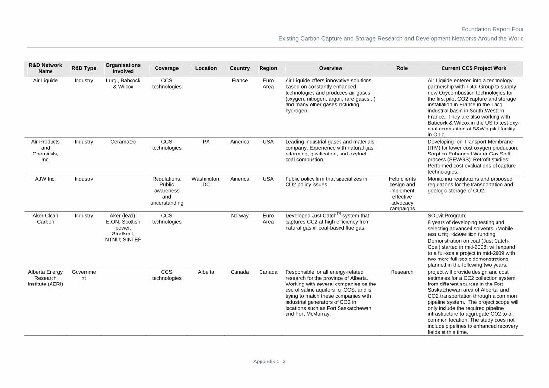
Foundation Report FourExisting Carbon Capture and Storage Research and Development Networks Around the World
Appendix 1 -3
R&D Network Name R&D Type Organisations
Involved Coverage Location Country Region Overview Role Current CCS Project Work
Air Liquide Industry Lurgi, Babcock & Wilcox
CCS technologies
France Euro Area
Air Liquide offers innovative solutions based on constantly enhanced technologies and produces air gases (oxygen, nitrogen, argon, rare gases...) and many other gases including hydrogen.
Air Liquide entered into a technology partnership with Total Group to supply new Oxycombustion technologies for the first pilot CO2 capture and storage installation in France in the Lacq industrial basin in South-Western France. They are also working with Babcock & Wilcox in the US to test oxy-coal combustion at B&W's pilot facility in Ohio.
Air Products and
Chemicals, Inc.
Industry Ceramatec CCS technologies
PA America USA Leading industrial gases and materials company. Experience with natural gas reforming, gasification, and oxyfuel coal combustion.
Developing Ion Transport Membrane (ITM) for lower cost oxygen production; Sorption Enhanced Water Gas Shift process (SEWGS); Retrofit studies; Performed cost evaluations of capture technologies.
AJW Inc. Industry Regulations, Public
awareness and
understanding
Washington, DC
America USA Public policy firm that specializes in CO2 policy issues.
Help clients design and implement effective advocacy
campaigns
Monitoring regulations and proposed regulations for the transportation and geologic storage of CO2.
Aker Clean Carbon
Industry Aker (lead); E.ON; Scottish
power; Stratkraft;
NTNU; SINTEF
CCS technologies
Norway Euro Area
Developed Just CatchTM system that captures CO2 at high efficiency from natural gas or coal-based flue gas.
SOLvit Program; 8 years of developing testing and selecting advanced solvents. (Mobile test Unit) ~$50Million funding Demonstration on coal (Just Catch-Coal) started in mid-2008; will expand to a full-scale project in mid-2009 with two more full-scale demonstrations planned in the following two years.
Alberta Energy Research
Institute (AERI)
Government
CCS technologies
Alberta Canada Canada Responsible for all energy-related research for the province of Alberta. Working with several companies on the use of saline aquifers for CCS, and is trying to match these companies with industrial generators of CO2 in locations such as Fort Saskatchewan and Fort McMurray.
Research project will provide design and cost estimates for a CO2 collection system from different sources in the Fort Saskatchewan area of Alberta, and CO2 transportation through a common pipeline system. The project scope will only include the required pipeline infrastructure to aggregate CO2 to a common location. The study does not include pipelines to enhanced recovery fields at this time.

Foundation Report FourExisting Carbon Capture and Storage Research and Development Networks Around the World
Appendix 1 -4
R&D Network Name R&D Type Organisations
Involved Coverage Location Country Region Overview Role Current CCS Project Work
Alberta Geological
Survey
Government
CCS technologies
Alberta Canada Canada Focused efforts on the potential for CO2 storage in geological media in Alberta as a mitigation strategy for reducing greenhouse gas emissions into the atmosphere.
Characterizing sites for geological storage of CO2.
Alberta Research Council
Government
CCS technologies, Economics
Alberta Canada Canada Endeavours to be a pioneer in developing innovative ways of converting, capturing, and storing carbon.
Research activities include: Gasification (CO2 conversion); Gas separation (CO2 capture); Geological storage (modelling, economics, monitoring, measurement and verification; CO2 enhanced coalbed methane (ECBM) recovery; CO2 enhanced oil recovery (EOR); acid gas injection; Storage in deep saline aquifers)
Alstom Industry CCS technologies
CT America USA Alstom is developing the Chilled Ammonia Process technology for post-combustion capture of CO2 and is collaborating with Dow to develop improved amine-based post combustion capture solvents. In addition Alstom is developing oxy-coal combustion technology and a chemical looping process.
Technology developer and
technology supplier
The Chilled Ammonia Process is being demonstrated in We Energies' Pleasant Prairie Power Plant (Wisconsin, USA). Additional plants are planned with E.ON in Sweden (5MW demo), AEP (30 MW and 200 MW), and Statoil (40 MW). Advanced Amine pilot will be installed at Dow Chemical facility in West Virginia.
AMEC Plc Industry CCS Technologies;
Economics
London UK Euro Area
A focused supplier of high-value consultancy, engineering and project management services to the world’s energy, power and process industries.
Consulting Advanced Oil Recovery studies and research into distributed transmission, capture of CO2 and cost modelling.
American Electric Power
(AEP)
Industry Alstom CCS technologies
OH; WV America USA In March 2007 APE announced a two-phase program that will retrofit and demonstrate a 200-MW post-combustion capture system at its North-eastern Station in Oologah, Oklahoma by the end of 2011.
Funder, project developer, first
user, and operator
Chilled Ammonia Process: Phase 1 is a 30 MWth pilot plant to capture 100,000 tonnes (110,231 tons) of CO2 from flue gas emitted from 1300 MW Mountaineer Plant in West Virginia. Captured CO2 will be stored in deep saline deposits at the site. Phase 1 scheduled for start-up at end of 2009. Phase 2 is a demonstration plant that will take a slipstream from one of the 450 MW units at Northeastern Station. It will capture 1.5 million tonnes (1.6 million tons) of CO2 per year for EOR. Phase 2 scheduled for start-up in late 2011.

Foundation Report FourExisting Carbon Capture and Storage Research and Development Networks Around the World
Appendix 1 -5
R&D Network Name R&D Type Organisations
Involved Coverage Location Country Region Overview Role Current CCS Project Work
Anglo American
Services (UK) Limited
Industry Victoria Australia ANZ Anglo American is one of the world’s major diversified mining groups.
coal producer Have a Clean Coal Energy Alliance with Shell which is evaluating the Monash Energy project, incorporating carbon capture and storage, in the state of Victoria, Australia. Anglo Coal is also part of The FutureGen Industrial Alliance, which consists of major energy and mining companies working in partnership with the US Department of Energy (DOE) to design, construct, and operate the world’s first ‘near zero emissions’ coal-fuelled power generation plant.
Arcelor Research SA
Industry ULCOS CCS technologies
Luxembourg Luxembourg
Euro Area
Working with a consortium of 48 other companies across Europe to reduce carbon dioxide produced by steel making
Research One of the leading players in the EU sponsored Ultra-Low CO2 Steel-Making project (ULCOS). Four options are being tested at industrial scale until 2012. Doing similar work with the American Iron and Steel Institute in the USA and World Steel Association across the world.
Arizona State University
Academia CCS technologies
AZ America USA Membrane Development Research integrate the water gas shift reaction with a CO2 selective membrane to separate CO2 from shifted synthesis gas (DOE share: $656,316; recipient share: $164,088; duration: 48 months)

Foundation Report FourExisting Carbon Capture and Storage Research and Development Networks Around the World
Appendix 1 -6
R&D Network Name R&D Type Organisations
Involved Coverage Location Country Region Overview Role Current CCS Project Work
ARUP Pty Ltd Industry UK Euro Area
A multidisciplinary organisation primarily focused on construction.
Research Arup and the Centre for Process Innovation (CPI) are moving ahead with their efforts to develop engineering systems to scale up a novel idea that could revolutionise carbon capture. The organisations have developed a system of using algae, which draws on the carbon dioxide (CO2) emitted by power stations and factories. It closes the carbon cycle, using wastes to produce environmentally friendly bio-based products, reducing reliance on fossil fuels and artificial chemicals in crop growth. “We are planning a rapid research and development programme to move the concept from small-scale testing to larger scale demonstration. We are also looking at ways of integrating the processes into existing power supply and waste management systems. “
Asia Pacific Partnership
(APP)
Collaborative
CCS Technologies;
Information Sharing
Korea; Japan; China; India
East Asia (ex.
Japan); Japan; China; India
Coal Mining Task Force will work collaboratively with the Cleaner Fossil Energy Task Force to ensure that synergies are captured in improving coal processing and developing new coal-based generation technologies. Identify current reclamation activities in each country, as appropriate, and exchange best practice information in reclamation of surface mined lands with a focus on enhanced surface reclamation practices that improve the opportunities for carbon sequestration.
Research
Aurecon Australia Pty
Ltd.
Industry Information sharing; Political
Regional and Environmental
Issues
Australia ANZ offering sustainability and climate change services including CCS
consulting, project
development

Foundation Report FourExisting Carbon Capture and Storage Research and Development Networks Around the World
Appendix 1 -7
R&D Network Name R&D Type Organisations
Involved Coverage Location Country Region Overview Role Current CCS Project Work
Australian Coal Association
(ACA)
Collaborative
CCS technologies,
Public Awareness
and Understanding
New South Wales and
Queensland
Australia ANZ Established 1 billion+ AUD COAL21 fund for supporting the development and demonstration of low emission coal power technology.
Funder, public outreach
committed to make 'up to' AUS $400m (USD $351m) available over the next ten years, for clean coal technology demonstration projects in New South Wales.
Australian National Low
Emissions Coal Research
and Development (ANLEC R&D)
Collaborative
NLECC CCS technologies, Economics
Australia ANZ established to manage NLECC's R&D investments as part of its national strategy; collaborate with and help provide funding to various research organisation including CSIRO and the Universities to perform needs driven R&D to support the construction, commissioning and early operation of the project
Research, Coordination
• ANLEC R&D will use the focussed industry feedback from the Flagship demonstration projects project to drive an R&D program that helps reduce project risk, improve future project performance and drive relevant technology development. • A coordinated research program can help demonstrate that the operating process is a safe and permanent method of emission reduction. Verification by an independent and publicly recognised research organisation is an essential element for confirming the integrity of the CCS process and gaining public acceptance of CCS. • The ANLEC R&D research program may also provide data and co-ordinated research to help with environmental permitting, stakeholder engagement and help fulfil the knowledge transfer obligations that are likely to result from public funding.
Australian Pipeline Industry
Association Research and
Standards Committee
Industry http://www.pipeliner.com.au/Directory/browse.ph
p
CCS Technology
Canberra Australia ANZ An association of more than 400 members including contractors, owners, operators, engineering companies and suppliers of pipeline products and services and advisers on a range of issues. The APIA is the peak national body representing the interests of Australia’s high-pressure transmission pipeline sector.
Research

Foundation Report FourExisting Carbon Capture and Storage Research and Development Networks Around the World
Appendix 1 -8
R&D Network Name R&D Type Organisations
Involved Coverage Location Country Region Overview Role Current CCS Project Work
Babcock & Wilcox (B&W)
Industry Air Liquide; American
Electric Power; Black Hills
Corp; Battelle
CCS technologies
OH America USA B&W is active in developing absorption systems using advanced amines for post combustion capture. Also active in developing oxy-fuel technology.
Design; Development, Technology
supplier
Clean Environment Development Facility (30 MWth) was converted in 2007 to support oxy-coal design work. Facility includes a full-scale burner, convection pass, dry ESP, wet FGD, and a baghouse. Submitted proposal to DOE's Restructure FutureGen for a 100 MW oxy-combustion plant for Black Hills Corporation in Nebraska.
BASF Industry Linde CCS technologies
Ludwigshafen
Germany Euro Area
A new CO2 solvent developed by BASF and optimized capture plant technology developed by Linde form the basis of the optimized CO2 scrubbing technology.
The pilot CO2 scrubbing plant is being built by Linde at the 1,000-MW BoA 1 lignite-fired unit, which, with a net efficiency of over 43%, is the most modern and most efficient lignite-fired unit worldwide.
Basin Electric Cooperative
Industry Powerspan; Encana
CCS technologies
ND America USA Parent company to the largest carbon capture project in the world. Through Dakota Gasification Company, been capturing CO2 from Great Plains Synfuels Plant since 2000. Gas is compressed and sent via a 328 km (205 mile) pipeline to Weyburn, Saskatchewan.
Funder, project developer, first
user, and operator
Dakota Gasification Company has joined a research project coordinated by the Petroleum Technology Research Centre, Regina, Saskatchewan, to study and confirm the feasibility of permanent CO2 containment within a geological reservoir. Also planning large-scale demonstration of CO2 capture from a slipstream of flue gas from Antelope Valley Unit 1 (120 MW). The captured CO2 would be used for possible EOR operations in oil fields of western North Dakota.
Bechtel Industry CCS technologies
TX; CA; MD America USA Offers engineering, construction, and project management services.
Engineering, Procurement, Construction
Working on polygeneration projects; investigating using CO2 for EOR and then permanently stored underground.
Bellona CCS Web
Industry Information sharing
Oslo Norway Euro Area
Bellona advocates enhanced energy efficiency, renewable energy and CCS as the strategies to reduce global CO2 emissions. Bellona has also taken on the challenge of educating industry about the advantages of CCS and is widely consulted by industrial stakeholders on all issues related to CCS.
Publisher Bellona is very involved in the fight against global climate change and has produced reports for the public, other NGOs and world leaders offering alternatives to current energy and transportation structures which produce fewer greenhouse gases in a safe and profitable way.
BHP Billiton Industry CCS Technologies
Victoria Australia ANZ Affiliated with the CO2CRC Otway Project

Foundation Report FourExisting Carbon Capture and Storage Research and Development Networks Around the World
Appendix 1 -9
R&D Network Name R&D Type Organisations
Involved Coverage Location Country Region Overview Role Current CCS Project Work
Black & Veatch Industry CCS technologies
Kansas America USA Identifies, assesses, designs, engineers and implements viable CCS projects.
Engineering, Procurement, Construction
Provides greenhouse gas reduction services in the areas of: developing climate change strategies and solutions; carbon emissions profiling; risk assessment; and risk management solutions.
Booz Allen Hamilton
Industry CCS technologies, Economics
McLean, Virginia
America USA A leading strategy and technology consulting firm; provides capture systems analysis.
Consultant Prepared report comparing IGCC and PC plant costs (September 2004)
Booz and Co. Industry Economics America ANZ consulting, project
management,
BP Alternative Energy
Industry CCS technologies
UK; Australia; America;
China
Euro Area; ANZ; USA; China
BP aims to be a leading member in the CCS community.
Funder, project developer, first
user, and operator
Running CCS project in Algerian Sahara; BP is currently vice-chair of ZEP and also helped to establish the world’s first industry association for CCS, the UK-based Carbon Capture and Storage Association.; BP is also a partner in the Otway Basin storage demonstration project in Australia, which is storing approximately 100,000 tonnes (110231 tons) of CO2 at a depth of 2,000 metres (6562 feet) and will undertake extensive monitoring.; In 2007, BP formed an independent joint venture with Rio Tinto, Hydrogen Energy, to develop large scale commercial power generation projects where CCS would be used to eliminate most of the carbon dioxide emissions from hydrocarbon feedstock with electricity being generated from the remaining hydrogen.
Brigham Young
University
Academia Sustainable Energy
Solutions
CCS technologies,
Public Awareness
and Understanding
Provo, Utah America USA Developing Cryogenic Carbon Capture Technology. It is designed to separate a nearly pure stream of CO2 from power plant gases.
Research and Development,
Education
The technology is being commercialized by Sustainable Energy Solutions and is licensed from the Fulton College of Engineering and Technology at Brigham Young University.

Foundation Report FourExisting Carbon Capture and Storage Research and Development Networks Around the World
Appendix 1 -10
R&D Network Name R&D Type Organisations
Involved Coverage Location Country Region Overview Role Current CCS Project Work
British Geological
Survey (BGS)
Government
CCS technologies
UK Euro Area
Potential chemical interactions of injected CO2 with the surrounding rocks storage site monitoring technologies and integrated monitoring strategies assessment of long-term site performance including evaluating consequences of potential leakage
Advisory; Regulations
co-leads the geological storage work-package for NZEC alongside the China University of Petroleum (CUP, Beijing) NERC-funded CRIUS (CO2 Reactions In Underground Storage) project
Bundesanstalt für
Geowissenschaften und Rohstoffe
(BGR)
Government
CCS technologies, Economics,
Political Regional and Environmental
Issues
Germany Euro Area
Affiliated w/ GESTCO, NASCENT, CO2STORE, and CASTOR as well as the membership in the network CO2GEONET. BGR so as we find out more about those networks we will know more about Coverage type
Research and Development,
Policy Research
Catalogue of Storage Capacities in Germany CSEGR Carbon Sequestration with Enhanced Gas Recovery GeoCapacity Information system about CO2 Sources and Storage Options
Bureau de Recherches
Geologiques et Minieres (BRGM)
Institute CCS technologies
Orleans France Euro Area
France's leading public institution involved in the Earth Science field for the sustainable management of natural resources and surface and subsurface risks.
Research and Development
Currently involved in CO2ReMoVe (2006-2010), GRASP (2006-2010). Previously involved in ULCOS (2004-2008), CASTOR (2004-2007), CO2STORE (2003-2006), CO2GeoNet (2004-2009), InCA-CO2 (2004-2007), EU GeoCapacity (2006-2009), CO2NET (2006-2008).
Burns & McDonnell
Industry CCS technologies, Economics,
Political Regional and Environmental
Issues
Kansas City, Missouri
America USA Provides engineering, architectural, construction, environmental and consulting services to a broad range of clients across a multitude of industries.
Engineering, Procurement, Construction
Partner with Basin Electric Power Coop and Powerspan to demo CO2 removal from flue gas of a lignite-based boiler by adding CO2 capture and sequestration (CCS) to Basin Electric's existing Antelope Valley Station, located near Beulah, N.D. Powerspan's ECO2 ammonia-based technology will be used to capture CO2 on a 120-megawatt electric-equivalent gas stream from the 450 megawatt Antelope Valley Station Unit 1. With Kiewit Energy Co., will conduct FEED study and facility cost report for the Taylorville Energy Centre (coal gasification to SNG with power generation) in Illinois. This team has also been selected to perform EPC engineering design services for the Cash Creek coal-to-SNG project in Kentucky.

Foundation Report FourExisting Carbon Capture and Storage Research and Development Networks Around the World
Appendix 1 -11
R&D Network Name R&D Type Organisations
Involved Coverage Location Country Region Overview Role Current CCS Project Work
Business Roundtable
(USA)
Industry Keybridge Research; SFA
Pacific; University of Maryland; Eastman Chemical
Economics, Public
Awareness and
Understanding
Washington DC
America USA An association of CEOs of leading US companies. Business Roundtable unites these top CEOs, amplifying their diverse business perspectives and voices on solutions to some of the world's most difficult challenges. Combining those insights with policy know-how, Business Roundtable innovates and advocates to help expand economic opportunity for all Americans.
Policy Research
Analysed cost of CCS from power and industrial sources of CO2 and compared to other options such as fuel switching (natural gas, biomass)
Calera Corporation
Industry CCS technologies
Los Gatos, CA
America USA The company makes cement and uses CO2 as a reactant in its process. Calera's approach is to react CO2 in flue gas with calcium and magnesium in seawater to make a cement-like material.
Small demonstration on a slip stream from a natural gas power plant in Moss Landing, California.
California Energy
Commission (CEC)
Government
WESTCARB CCS technologies
CA America USA The Energy Commission's Research Development and Demonstration (RD&D) Division supports public interest energy research, development, and demonstration.
Funder, Research,
Development
RD&D activities include providing contracts and grants for research and development of energy technologies and related scientific activities., CEC is also the lead organisation for the West Coast Regional Sequestration Partnership (WESTCARB).
Calix Limited Industry CCS Technologies
Gordon Australia ANZ Calix Carbon Capture ("3C") uses metal oxides (metals being calcium or magnesium) to react with CO2 producing calcium carbonate or magnesium carbonate.
Developer In 2007, attempted to raise funds to support a pilot demonstration of the technology. The website did not provide a recent progress report, so it is unclear if the pilot was built and/or if it has operated successfully.
Canadian Clean Power
Coalition (CCPC)
Industry SaskPower; BEPC; EPCOR; EPRI; Sherritt International;
TransAlta; Nova Scotia Power,
AERI
CCS technologies, Economics
Canada Canada Group of utility companies representing 90 percent of coal-fired generation in Canada collaborating to research, develop and demonstrate commercially viable clean coal technology.
Collaborative Research
The results of Phase I yielded some technology gaps that are currently being studied in Phase II. The primary one is to improve gasification technologies for low rank coals such as lignite and sub-bituminous. Phase II will also optimize the amine scrubbing and oxyfuel combustion technologies. Polygeneration projects will also be assessed. Business cases for potential demonstration project sites will also be prepared.

Foundation Report FourExisting Carbon Capture and Storage Research and Development Networks Around the World
Appendix 1 -12
R&D Network Name R&D Type Organisations
Involved Coverage Location Country Region Overview Role Current CCS Project Work
CanmetENERGY
Government
The Canadian CO2 Capture &
Storage Technology
Network
CCS technologies - Measurement,
Monitoring, Verification (MMV); Well
bore Integrity, Capacity
Estimation, Effects of
Impurities in the flue stream
on Saline Reservoirs, CO2 fate Modelling
Ottawa Canada Canada Canadian leader in clean energy research and technology development. With over 450 scientists, engineers and technicians and more than 100 years of experience, CanmetENERGY is Canada's knowledge centre for scientific expertise on clean energy technologies.
Research, funder,
technology developer
Investigating two options they believe offer cost benefits: - One option that they term hydroxy-fuel technology, steam and/or water is used to control the flame temperature. This concept has been tested successfully in the VCRF and CANMET believes that eliminating the need for secondary RFG reduces the capital and operating costs of oxy-fuel combustion and therefore improves the economics of the process. No additional details are available at present. - The second option is an oxygen-fired slagging combustor design. The feasibility of this option is currently being evaluated and if found attractive a pilot plant will be built. As the design does not involve any additional flow for flame attemperation, it offers the prospect of greater size reductions than achieved by the hydroxy-fuel design. Currently has projects for computational fluid dynamics (CFD) modelling of both oxy-fuel combustion and gasification. The CFD modelling tools are used to help design and troubleshoot these advanced-cycle systems.
Capital Power Industry Government of Canada;
Enbridge Inc.; Alberta Saline Aquifer Project
CCS technologies
Alberta Canada Canada Collaborative developing Genesee post-combustion demonstration project, and an IGCC project with pre-combustion capture
Project developer, operator
The post-combustion capture project focuses on the development of amine scrubbing technology to remove CO2 from the flue gas of a coal-fired power plant. IGCC project will build a 270 MW plant at the Genesee power station location. CO2 will be used for EOR or delivered by Enbridge for permanent geologic storage.

Foundation Report FourExisting Carbon Capture and Storage Research and Development Networks Around the World
Appendix 1 -13
R&D Network Name R&D Type Organisations
Involved Coverage Location Country Region Overview Role Current CCS Project Work
CAPTEC Industry ECN CCS technologies
Netherlands
Euro Area
A research programme of 6 Dutch consortium partners. The programme runs from 2006 until 2009 and is coordinated by ECN.
New low-temperature polymer CO2 membranes for partial CO2 removal from flue gases; New advanced chemical and hybrid solvents with low regeneration energy consumption for post- and pre-combustion CO2 capture; Novel air separation technologies for oxy fuel Zero-emission power plants; Pre-combustion CO2 capture (Sorption-enhanced water-gas shift and membrane reactors) for IGCC; Integration of CO2 capture in power stations, technical and economic evaluation and infrastructure aspects; Dissemination and co-ordination with CATO project
Carbon Capture and
Storage Association
Industry Coal Authority, PowerFuel, Rio
Tinto, Sasol
CCS technologies
London UK Euro Area
Promotes the business of capture and geological storage of carbon dioxide as a means of abating atmospheric emissions of carbon dioxide and, potentially, as a means of enhancing the production of fossil hydrocarbons
Educating and providing
information to policy makers
and stakeholders.
The Association works to raise awareness, both in the UK and internationally, of the benefits of CCS as a viable climate change mitigation option, and the role of CCS in moving towards a low-carbon global economy.
Carbon Sequestration
Leadership Forum (CSLF)
Government
US Dept of Energy
CCS technologies, Economics,
Political Regional and Environmental Issues, Public
Awareness and
Understanding
Washington DC
America USA A Ministerial-level international climate change initiative that is focused on the development of improved cost-effective technologies for the separation and capture of carbon dioxide (CO2) for its transport and long-term safe storage
Research coordination,
policy development
CANMET Energy Technology Centre (CETC) R&D Oxyfuel Combustion for CO2 Capture CO2 Capture Project CO2CRC Otway Project CO2 GeoNet CO2 Separation from Pressurized Gas Stream CO2 SINK ENCAP Feasibility Study of Geologic Sequestration of CO2 in Basalt Formations of (Deccan Trap) in India Frio Project Geologic CO2 Storage Assurance at In Salah, Algeria IEA GHG Weyburn-Midale CO2 Monitoring and Storage Project ITC CO2 Capture with Chemical Solvents

Foundation Report FourExisting Carbon Capture and Storage Research and Development Networks Around the World
Appendix 1 -14
R&D Network Name R&D Type Organisations
Involved Coverage Location Country Region Overview Role Current CCS Project Work
Carbozyme, Inc.
Industry CCS technologies
NJ America USA Developing a CO2-selective membrane, which is actually an aqueous solution of carbonic anhydrase enzyme that is mechanically stabilized in a hollow fibber membrane device.
Technology has been tested in the lab to obtain permeation rates of CO2 using simulated flue gas.
Carnegie Mellon
Electricity Industry Centre
Academia Sloan; Electric Power
Research Institute (EPRI);
U.S. National Science
Foundation; U.S.
Environmental Protection Agency;
U.S. Department of
Energy, Tennessee
Valley Authority; the U.S. Office
of Naval Research, McDermott
Technology; the ABB Group, Alliant Energy; National Rural
Electrical Cooperative Association;
the Commonwealth of Pennsylvania Office of Energy and Technology
Development
Regulations PA America USA Created jointly with EPRI and has a strategic focus. Address issues of middle and longer-term importance to the industry, as well as some non-traditional issues not being addressed by others.
Research, Education
Developed performance and cost models of Amine scrubbing of conventional coal plants and for a Selexol-based CO2 absorption system for capturing CO2 from IGCC plants.; Used a capacity planning and dispatch model to examine carbon capture and sequestration (CCS) in a multipollutant framework, focusing on a regional electricity market (the MAAC NERC region).

Foundation Report FourExisting Carbon Capture and Storage Research and Development Networks Around the World
Appendix 1 -15
R&D Network Name R&D Type Organisations
Involved Coverage Location Country Region Overview Role Current CCS Project Work
Carnegie Mellon
University
Academia Public Awareness
and Understanding
, Political regional and
environmental issues
Pittsburgh, PA
America USA Research deals with technical, economic and policy issues related to energy and the environment
Research, Education,
Policy Research
Research sponsored by the DOE has developed the Integrated Environmental Control Model (IECM), a computer-modelling program that performs a systematic cost and performance analyses of emission control equipment at coal-fired power plants. The IECM allows the user to configure the plant to be modelled from a variety of pollutant control technologies, including carbon capture and sequestration. Also, researchers at the Climate Decision Making Centre will work directly with and provide support and tools to policy decision makers.
CATO Industry EBN; ECN; Ecofys;
GasTerra; Geochem
Research BV; KEMA; Leiden
University; NAM; Natuur en Milieu; Shell; St.
Greenpeace Nederland; TNO
Built Environment
and Geosciences; TNO Science and Industry;
TU Delft; UCE; Utrecht
University Chemistry;
Utrecht University
Copernicus; Utrecht
University Geosciences;
UTwente; WWF
CCS technologies;
Public Awareness
Netherlands
Euro Area
The CATO programme is implemented by a strong consortium of Dutch companies, research institutions, universities and environmental organisations, led by the Utrecht Centre for Energy research (UCE). The program contains seven work packages: 1) system analysis 2) capture 3) storage 4) immobilization 5) monitoring 6) communication 7) knowledge dissemination
Research The program contains seven work packages that include projects in the areas of systems analysis, infrastructure and transition management; CO2 capture; CO2 storage; and immobilization of CO2 as a carbonate. Their website has a library database of more than 200 technical presentations on topics relating to CO2 capture.

Foundation Report FourExisting Carbon Capture and Storage Research and Development Networks Around the World
Appendix 1 -16
R&D Network Name R&D Type Organisations
Involved Coverage Location Country Region Overview Role Current CCS Project Work
Central Research Institute of
Electric Power Industry (CRIEPI)
Institute CCS technologies, Economics
Japan Japan A Japanese non-profit public benefit corp. to undertake R&D activities related to energy and the environment; Engaged in research on a broad range of topics
Research Developing advanced IGCC system with CO2 capture. An oxy-fuel gas turbine is used, CO2 separation system is not needed. Engaged in socio-economic analysis and policy assessment for CO2 issues, including emission trading.
Centre for Advanced
Energy Studies
Government
Boise State University; Idaho State University;
University of Idaho; Idaho
National Laboratory;
Private industry; US Department
of Energy
CCS technologies
America USA CAES integrates resources, capabilities and expertise to create new research capabilities, expand researcher-to-researcher collaborations, and enhance energy-related educational opportunities.
Research Investigating suitability of layered basalt as targets for industrial CO2 sequestration
Centre for Low Emission
Technology
Collaborative
State of Queensland,
CSIRO, Australian Coal
Research Limited,
Stanwell, Tarong Energy,
University of Queensland
CCS technologies
Kenmore, QLD
Australia ANZ A partnership between world class R&D providers making it possible for Australia to continue using coal to provide abundant, economical power in an environmentally and sustainable manner via production of zero carbon electricity and hydrogen
Research

Foundation Report FourExisting Carbon Capture and Storage Research and Development Networks Around the World
Appendix 1 -17
R&D Network Name R&D Type Organisations
Involved Coverage Location Country Region Overview Role Current CCS Project Work
CEPAC Industry PETROBRAS; Brazilian
Agency for Oil, Gas and Biofuels;
National Energy Technology Laboratory
(NETL); Department of
Energy (DOE) - U.S.A.;
Lawrence Livermore National
Laboratory - U.S.A.; Carbon Sequestration
Leadership Forum (CSLF) - U.S.A.; French
Energy Commission
(CEA) - France; Aveiro
University - Portugal; Fernando Pessoa
University - Portugal; UCG Partnership; COPELMI
Mining Co.; National
Scientific and Technological Development
Council (CNPq); Brazilian Coal Association
(ABCM); Santa Catarina Coal
Industry Association
(SATC); Coal Network - Coal
Research, Development and Inclusion
Network; ECOAR
CCS Technologies
Brazil South America
Research Research program for integrity evaluation, characterization and quality prediction of oil reservoirs and saline aquifers - The PRORESERVA research program aims for the geologic and mineralogic characterization of potential reservoirs for CO2 storage, and the study of their interaction with the injected carbon dioxide, by means of laboratory experiments and numerical simulations. Clean and Sustainable Coal Program - The Clean and Sustainable Coal Program relies on advanced laboratory facilities to provide a complete portfolio of R&D projects for study of conventional and unconventional energy-supplying/providing uses of coal such as coal bed methane (CBM), enhanced coal bed methane (ECBM), and coal-derived hydrogen via underground coal gasification (UCG).

Foundation Report FourExisting Carbon Capture and Storage Research and Development Networks Around the World
Appendix 1 -18
R&D Network Name R&D Type Organisations
Involved Coverage Location Country Region Overview Role Current CCS Project Work
CESAR Industry TNO Science and Industry,
Alstom Power, BASF SE,
Centre National de la Recherche
Scientifique (CNRS), DONG
Energy Generation,
Doosan Babcock Energy
Limited, Electrabel s.a.,
E-ON Engineering
GmbH, EON-UK, GDF SUEZ,
IFP, The Norwegian
University of Science and Technology, Polymem,
Public Power Corporation S.A., RWE Power AG,
RWE Npower PLC, Siemens
Aktiengesellschaft, Stiftelsen
SINTEF, StatoilHydro
ASA, University of
Kaiserslautern, Vattenfall R&D
Sweden
CCS technologies
Coordinator location:
Delft
Netherlands
Euro Area
European Framework Program 7 (FP7) project coordinated by TNO and is the continuation of CASTOR (Capture and Storage), a FP6 project.
CESAR aims for a breakthrough in the development of low-cost post-combustion CO2 capture technology to provide economically feasible solutions for both new power plants and retrofit of existing power plants which are responsible for the majority of all anthropogenic CO2 emissions.
CH2MHill Industry Economics, Political
regional and environmental
issues
Englewood, CO
America USA Serves both large and small industrial clients by providing solutions that solve the air quality challenges that exist today.
Engineering, Consulting,
Environmental Permitting
Supports timely new source permitting, cost-effective compliance with existing permit requirements, and minimizing corporate liability; Experience in building GHG accounting systems from the ground up.

Foundation Report FourExisting Carbon Capture and Storage Research and Development Networks Around the World
Appendix 1 -19
R&D Network Name R&D Type Organisations
Involved Coverage Location Country Region Overview Role Current CCS Project Work
Chalmers University of Technology
Academia Vattenfall CCS technologies
Gothenburg Sweden Euro Area
Chalmers is a Swedish university of technology in which research and teaching are conducted on a broad front within technology, natural science and architecture.
Research, Education
Research on Oxyfuel combustion has been performed since 2001. The 100 kW test rig was first built for gas combustion, but has been reconstructed and can now handle both gas and pulverised coal; CO2 capture research on chemical looping combustion and CO2 sequestration
Chevron Energy
Technology Co.
Industry CO2 Capture Project
CCS technologies
America USA Covers storage, monitoring and verification including certification framework, wellbore integrity field study, geochemical-geotechnical simulation, CO2 ECBM operations and geophysical monitoring, and remote sensing.
Research, Project
Development, Operator
Developing effective methods to capture significant amounts of CO2 emitted from power generation and industrial sources and store the gas in geologic formations below the earth's surface.
China Huaneng
Group
Xueyuan Nanlu, Beijing
China China Member of the FutureGen alliance and is a 50% funder of the consortium of Chinese Power and coal companies (including Peabody) that are supporting the GreenGen 250 MW IGCC + CCS project
Funder A 3000 tpy CO2 PCC project that started in June 2008 using amino alcohol (SIC) and are planning a 150,000 tpy PCC project to be built at their Shidongkou plant in 2011.

Foundation Report FourExisting Carbon Capture and Storage Research and Development Networks Around the World
Appendix 1 -20
R&D Network Name R&D Type Organisations
Involved Coverage Location Country Region Overview Role Current CCS Project Work
Chinese Academy of
Science (CAS)
Academia BP CCS Technologies; Regulations
CAS Shanghai Pudong
Science and Technology Innovation
Park
China China Comprehensive State-run Research Institute. Focuses on Storage and Technology advancements
Research; Education
BP and CAS have agreed to establish the Clean Energy Commercialization Centre (CECC), a joint venture in Shanghai investing some $73 million to commercialize Chinese clean energy technologies. Subject to final government approvals, the CECC venture is expected to be established in 2009. The CECC will serve as an international platform for further collaboration among research institutes, enterprises and other institutions to improve indigenous Chinese innovation capabilities and market applications in areas such as clean coal conversion, zero emission technologies, and carbon capture and storage. Independently, CAS is also coordinating R&D related to: Fuel-flexible gasification, CO2 capture-ready designs, one-step system for coal to SNG, Syngas heat recovery, Warm syngas cleanup, Continuous coal feed and ash removal
Chiyoda Corporation
Industry Yokohama Japan Japan Chiyoda Corporation has constructed numerous plants in Japan and around the world in fields including oil, gas and other energy resources; petrochemicals and chemicals; pharmaceuticals; and general industry. In 1972, Chiyoda published a pamphlet entitled "Legacy for the Twenty-first Century" that propounded sustainable social development by harmonizing nature and industrial development. It declared Chiyoda's intention as an engineering company to provide solutions to both energy and environmental issues through engineering and technological development.
Engineering and
Construction

Foundation Report FourExisting Carbon Capture and Storage Research and Development Networks Around the World
Appendix 1 -21
R&D Network Name R&D Type Organisations
Involved Coverage Location Country Region Overview Role Current CCS Project Work
CIUDEN Institute ENDESA CCS technologies
Leon Spain Euro Area
Building a large-scale CCS test platform consisting Oxyfuel pulverised coal and circulating fluidised be combustors. The main Oxyfuel train is followed by a CO2 purification unit that produces a high concentration CO2 stream.
El Bierzo Experimental Platform (Oxyfuel test facility)
Clean Air Task Force (CATF)
Institute Public awareness
and understanding,
Political Regional and Environmental
Issues
Boston, MA America USA A non-profit organisation dedicated to restoring clean air and healthy environments through scientific research, public education, and legal advocacy.
Policy Research,
Public Outreach
Working to educate the public, media, industry, and government officials on the science and economics of clean air policies through fact-based and locally appropriate advocacy.
Clean Energy Systems
(CES)
Industry WESTCARB; California Energy
Commission
CCS technologies
CA America USA CES Oxyfuel plant will provide the CO2 for WESTCARB's sequestration demonstration. The proposed test will inject the entire exhaust stream of the CES plant over a period of 4 years beginning in September 2012.
Technology developer and
technology supplier
WESTCARB, managed by the California Energy Commission, will oversee the creation, operation, and post injection monitoring of the proposed Project, and CES and partners will build, own, and operate a nominal 50 MW gas-fuelled plant with full carbon capture using technology already demonstrated at the same site on a 5 MW scale.

Foundation Report FourExisting Carbon Capture and Storage Research and Development Networks Around the World
Appendix 1 -22
R&D Network Name R&D Type Organisations
Involved Coverage Location Country Region Overview Role Current CCS Project Work
Climate Change Policy
Partnership
Academia Duke University CCS technologies,
Public Awareness
and Understanding, Economics,
Political Regional and Environmental
Issues
Durham, NC America USA The CCPP researches carbon-mitigating technology, infrastructure, institutions and overall systems in order to inform lawmakers and business leaders as they lay the foundation of a low-carbon economy.
Policy research, education
Evaluating pre- and post-combustion capture technologies to determine remaining technological barriers and to develop up-to-date cost, performance, and availability assumptions; Developed a geologic model to estimate the feasible storage capacity and cost of all major geologic reservoirs in the United States. In the process of using this model to develop geographic-based carbon storage supply curves; Developing a geographic information system (GIS) model to determine optimal CO2 pipeline routes that will connect the plants identified in the capture analysis with the best storage sites from the storage supply curve analysis; Will combine the three analytical components to develop cost estimates for a feasible CO2 capture, pipeline, and storage system. Expect to be able to make recommendations for policymakers about where and how to focus public investment.
CO2 Capture Project (CCP)
Industry British Petroleum (BP),
Chevron, ConocoPhillips,
ENI, EPRI, Petrobras,
Repsol, Shell, Statoil Hydro,
Suncor Energy, DOE, Norges forskningsråd, and European
Union Research Directorate, EU,
Klimatek NorCap, (BP,
Chevron, EnCana, Statoil, Shell, Suncor)
CCS technologies
America; The EU
USA; Euro Area
The CO2 Capture Project (CCP) is a partnership of eight of the world’s leading energy companies and three government organisations undertaking research and developing technologies to help make CO2 capture and geological storage (CCS) a practical reality for reducing global CO2 emissions and tackling climate change; Research network administered by Linda Curan
Cover CO2 capture; storage,
monitoring and verification
(SMV); policies and incentives
Oxy-firing Fluidized Catalytic Cracker, FCC; Best Integrated Technology, BIT; Best Integrated Technology, BIT; Hydrogen membrane reformer, HMR; Membrane Water Gas Shift, MWGS, and Membrane Reforming; Sorption Enhanced Water Gas Shift, SEWGS; Chemical Looping Reforming, CLR (two concepts)/One Step Decarbonization, OSD; HyGenSys(Steam, Methane Reformer and Gas Turbine); Coupled Geochemical-Geomechanical Simulation; Non-seismic monitoring of ECBM

Foundation Report FourExisting Carbon Capture and Storage Research and Development Networks Around the World
Appendix 1 -23
R&D Network Name R&D Type Organisations
Involved Coverage Location Country Region Overview Role Current CCS Project Work
CO2 Solution Inc.
Industry Alcoa CCS technologies
Quebec Canada Canada Developing an enzyme-based CO2 capture process. Carbonic anhydrase, a naturally occurring enzyme, catalyses CO2 (a rate increase of six is claimed) in the flue gas to the bicarbonate ion increasing the solubility of CO2 in water. The CO2 is released thermally by heating up the solution. The process is considered tolerant to impurities present in the flue gas. The anhydrase is also able to enhance the effectiveness of amine solvents such as MEA and MDEA by increasing the absorption rate and lowering the heat required for desorption.
Technology developer and
technology supplier
A prototype version of CO2 Solution’s technology was first tested in an industrial environment at Alcoa Inc.’s aluminium smelting facility at Deschambault, Quebec, Canada. Subsequent to this, the Company conducted an extended trial of the prototype reactor at the Quebec City, Canada waste incinerator. Both tests demonstrated that the enzyme functioned effectively and was stable in a real world environment. The Company expects the enzyme to have a life of approximately one year in commercial operations. The column would then have to be sent for recycling and a new column with fresh enzyme would be installed.
CO2-CASTOR Industry CCS technologies
Denmark Euro Area
CASTOR, "CO2 from Capture to Storage", is a European initiative grouping 30 partners (industries, research institutes and universities) coming from 11 different European countries and partially funded by the European Commission under the 6th Framework Program.
Conduct both carbon capture and geological
storage research.
Work on capture is aimed at developing new CO2 post-combustion separation processes suited to the problems of capture at low concentrations in large volumes of gases at low pressure.
CO2GeoNet Institute numerous European
organisations including BGS, BRGM, BGR,
TNO and others.
CCS technologies
Euro Area
European Network of Excellence on geological storage of CO2, sponsored by the European Commission under the 6th Framework Programme, promoting research integration within the scientific community to help enable the implementation of CO2 geological storage.
Integrate wide range of
knowledge and expertise
Working to deploy 10-12 large-scale demonstration projects within Europe by 2015

Foundation Report FourExisting Carbon Capture and Storage Research and Development Networks Around the World
Appendix 1 -24
R&D Network Name R&D Type Organisations
Involved Coverage Location Country Region Overview Role Current CCS Project Work
CO2NET Industry 30 major companies and organisations, across Europe, and from USA and Australia
CCS technologies,
Public Awareness
and Understanding, Economics,
Political Regional and Environmental
Issues, Information
Sharing
Euro Area
CO2NET is a Carbon Dioxide Knowledge Sharing Network, which was initially set up under the European Commission's FP5 Programme.
Educating and providing
information to policy makers
and stakeholders.
The now industry-led, self-funded Network comprises in excess of 30 of the major companies and organisations, across Europe, and from USA and Australia, who are extensively involved in the development of CCS.
CO2ReMoVe Industry Several including TNO;
BP; Statoil; GeoForchungZe
ntrum; Total; Wintershall; Vattenfall;
Schlumberger; Central Mining
Institute of Poland; British
Geological Survey;
CCS technologies
Euro Area
CO2ReMoVe is a consortium of industrial, research and service organisations with experience in CO2 geological storage.
Research The consortium proposes a range of monitoring techniques, applied over an integrated portfolio of storage sites.
CO2Sink Industry GFZ German Research Centre for
Geosciences
CCS technologies
Ketzin Germany Euro Area
CO2SINK is a European research project dealing with research on geological storage of CO2 as a means of reducing greenhouse gas emissions. The CO2SINK project is funded by the EU commission (FP6), the Federal Ministry of Economics and Technologies (BMWi), the Federal Ministry of Education and Research (BMBF) and the industry.
Research, Demonstration
The injection of CO2 has started on June 30th 2008. Up to June 21st 2009, 15.888 tonnes (17.514 tons) of CO2 have been injected underground into a saline aquifer near the town of Ketzin, west of Berlin.

Foundation Report FourExisting Carbon Capture and Storage Research and Development Networks Around the World
Appendix 1 -25
R&D Network Name R&D Type Organisations
Involved Coverage Location Country Region Overview Role Current CCS Project Work
CO2STORE Collaborative
Statoil is lead, other partners
include BP, ExxonMobil,
Norske Hydro, Total, Energi
E2, Industrikraft Midt-Norge, Progressive Energy Ltd, Vattenfall,
Schlumberger, IEA
Greenhouse Gas
Programme, and eight European research institutes
CCS technologies
Euro Area
Investigating widespread underground storage of CO2 in aquifers.
Research, Education
The project will investigate how lessons learned from the other previous projects on this matter (like SACS, GESTCO, NASCENT) can be implemented on other aquifers in Europe, not only offshore, but also under land. Through careful evaluation and application of both existing and novel approaches, the project will provide sound, scientifically- based methodologies for the assessment, planning, and long-term monitoring of underground CO2 storage.

Foundation Report FourExisting Carbon Capture and Storage Research and Development Networks Around the World
Appendix 1 -26
R&D Network Name R&D Type Organisations
Involved Coverage Location Country Region Overview Role Current CCS Project Work
Commonwealth Scientific and
Industrial Research
organisation (CSIRO)
Institute CCS technologies,
Public awareness
and understanding
NSW Australia ANZ; China
The Energy Transformed Flagship has established a post-combustion capture (PCC) research program investigating appropriate solvents and technologies for Australian brown and black coal power stations; The research will benefit from an A$8 million Asia-Pacific Partnership on Clean Development and Climate (AP6) grant for PCC research being provided by the Australian Federal Government
Identify optimum
implementation pathways for
PCC in Australian coal- and gas-fired
power stations; advances in
materials science and molecular
engineering to develop high-
efficiency solvents for
capturing CO2; options for
process optimisation and novel
integration; technologies for
gas conditioning
and separation for post-
combustion retrofit, with
optimum host plant energy integration.
Researchers have developed a 1 000 tonnes (1,102 tons per annum) per annum pilot plant that is transportable and can be retro-fitted to existing power stations. This is being used to capture CO2 emissions from different types of power stations, so that capture efficiency for a range of solvents and operations can be assessed prior to development of a much larger commercial-scale (50,000 tonnes (55,115 tons) per annum) plant. Working with Huaneng Group on a Beijing Power Plant.
ConocoPhillips (COP)
Industry CCS technologies
Houston, TX America USA Gasification technology licensor Technology developer and
technology supplier
ConocoPhillips is licensing its proprietary E-Gas™ technology to coal industry customers. The technology offers the potential to burn coal more cleanly while generating purer streams of carbon dioxide that can be used in industrial processes or injected to recover more oil from aging reservoirs and potentially more methane from coal beads.

Foundation Report FourExisting Carbon Capture and Storage Research and Development Networks Around the World
Appendix 1 -27
R&D Network Name R&D Type Organisations
Involved Coverage Location Country Region Overview Role Current CCS Project Work
Consortium for Clean Coal Utilization
Academia Washington University St.
Louis; Ameren; Arch Coal;
Peabody Coal
CCS technologies
St. Louis, MO
America USA Dedicated to addressing the scientific and technological challenges of ensuring that coal can be used in a clean and sustainable manner.
Research, Education
Lab-scale oxy-coal combustion research, investigating CO2 geochemistry
Cooperative Research Centre for
Greenhouse Gas
Technologies (CO2CRC)
Government
Geoscience Australia;
CSIRO; and numerous
universities, industries and governments
CCS technologies, Information
Sharing
Australia ANZ One of the world's leading collaborative research organisations focused on carbon dioxide capture and geological sequestration; An unincorporated joint venture comprising participants from Australian and global industry, universities and other research bodies from Australia and New Zealand, and Australian Commonwealth, State and international government agencies.
Research, Demonstration
Researching and developing technologies for capture and geological storage; Demonstration of capture and storage; Assessing the scope for the application carbon dioxide capture and storage in a range of different geographical, technical, and commercial settings; Information sharing and tech transfer. Pre-combustion capture trials at HRL's research gasifier, Mulgrave; Post-combustion capture demonstration at Hazelwood power plant; Software modelling and seismic studies.
COORETEC, Germany
Government; Industry
CCS technologies
Germany Euro Area
COORETEC is an initiative by the Federal Ministry of Economics and Technology (BMWi) for the development of a power plant fired by fossil fuels with prospects for the future. The abbreviation COORETEC stands for CO2 reduction technologies for fossil-fired power plants.
Research Investigating 1) Technologies for improving power plant efficiency and 2) Technologies for the separation and transport of CO2 with the aim of safe long-term storage in geological formations.
Cranfield University
Academia Nottingham, Newcastle,
Edinburgh and Leeds
Universities; E.ON UK;
Engineering and Physical Sciences Research Council
CCS technologies
Cranfield, Beds. and
Shrivenham, Oxon
UK Euro Area
Working with a team of industry and universities to study combustion and CO2 capture and transport technologies that could help meet UK’s emission reduction goals.
The University of Nottingham, University College London, Cranfield University, and Imperial College London are collaborating with Newcastle University to address some of the technical and material challenges of large-scale transportation of CO2 through pipelines. Nottingham’s expertise in chemical engineering, chemistry and mathematics will help the development of a transport pipeline network.

Foundation Report FourExisting Carbon Capture and Storage Research and Development Networks Around the World
Appendix 1 -28
R&D Network Name R&D Type Organisations
Involved Coverage Location Country Region Overview Role Current CCS Project Work
CS Energy Industry IHI Corporation; J-Power; Mitsui
& Co; Schlumberger; Xstrata Coal
CCS technologies
QLD Australia ANZ The Project aims to demonstrate how the oxy-fuel technology can be applied to an existing power station. Further, as a retrofit has a shorter lead time than a new plant, the project is expected to accelerate the development of the technology.
Demonstration Refurbishment of the Callide plant commenced mid 2008 to be followed by an extended period of air-blown operation to re-establish operational capability. Early in 2009 work on the oxy-coal retrofit will commence and be completed towards the end of 2010. The Demonstration Phase will run for four years to the end of 2014.
CSIC-INCAR Spanish
Research Council
Institute CCS technologies
Spain Euro Area
Investigating post combustion CO2 capture system using CaO
Research Modelling of a fluidized bed carbonator reactor to capture CO2 from a combustion flue gas; Capturing CO2 from Combustion Flue Gases with a Carbonation Calcination Loop.
Curtin University of Technology
Academia CCS technologies
Bentley, W.A,
Australia ANZ Opportunities for cryogenic and hydrate systems are being developed at Curtin University of Technology. This
Research Evaluate hydrate systems and cryogenic systems for cost effectiveness.
demosEUROPA
Industry See list of partners:
http://www.demoseuropa.eu/index.php?option=com_content&view=article&id=5
3&Itemid=59
Regulations; Public
awareness and
understanding; Political issues.
Warsaw Poland East Europe
The mission of demosEUROPA – Centre for European Strategy is to animate the debate about the main challenges facing the European Union. The Centre is a forum for exchange of opinions about the political, social and economic dimension of European integration and international affairs.
Information Sharing
demosEuropa Project entitled " CCS as a preferred technology for mainstreaming the clean use of coal in Poland" started may 2009 and to be complete by April 2011. Consists essentially of 3 reports namely: Regulatory and legislative issues; the impact of CCS legislation in Poland; Cooperation between business and R&D Centres. The project will also include a number of study visits, consultation and sharing between polish and British partners.
Denbury Resources
Industry CCS technologies
TX America USA work , focussed on pre-combustion and oxyfuels applications is looking promising in reducing capture costs
Project Developer, Operator
Denbury is providing CO2 from its Jackson Dome natural source for one of SECARB's storage demos, and will operate the pipeline and storage system for SECARB's second demo which will capture CO2 from a coal fired power plant. Denbury is also building additional CO2 pipelines in the US Gulf Coast to collect CO2 from industrial sources and transport it to oil fields for EOR.

Foundation Report FourExisting Carbon Capture and Storage Research and Development Networks Around the World
Appendix 1 -29
R&D Network Name R&D Type Organisations
Involved Coverage Location Country Region Overview Role Current CCS Project Work
Department of Resources, Energy and
Tourism
Government
Political, regional and
environmental issues
Canberra City, ACT
Australia ANZ Responsible for developing and maintaining government policies and programs for the resources, energy and tourism industries. Key objectives of the Department include: achieving strong economic growth; resilient and secure energy systems; equitable distribution of the benefits of Australia's energy, resources and tourism industries; and actively participating in a whole of government approach to domestic and international environmental policy.
Funding Demonstrate post combustion capture (PCC) with carbon capture and storage (CCS) in NSW Demonstrate post combustion capture (PCC) with carbon capture and storage (CCS) using lignite coal in Vic
Det Norske Veritas (DNV)
Industry Public awareness
and understanding,
Information Sharing
Oslo Norway Euro Area
As an independent provider of a broad service portfolio, DNV has the resources and integrity to play the leading role in the development of an end-to-end CO2 life cycle.
Consultant DNV has been selected by the European Commission to facilitate a process to shorten the time from policy making to industry implementation of Carbon Capture and Storage (CCS).
DONG Energy A/S
Industry RWE npower; Peel Energy
CCS technologies
Skærbæk Denmark Euro Area
RWE npower, Peel Energy and Denmark's Dong Energy have formed a joint venture partnership to develop a carbon capture and storage demonstration project in the UK.
Should the project be successful in the competition, it would comprise a capture facility of up to 400MW which would form part of a new cleaner supercritical coal-fired power station. It is proposed that the CO2 would then be transported to disused gas fields in the North Sea where it would be permanently stored. The project could be up and running by 2014.
Dooher Institute of
Physics and Energy/ Adelphi
University
Academia CCS technologies
NY America USA Validating that the thermodynamic penalty with using liquid CO2 as the carrier fluid for slurry-fed gasifiers is greatly reduced
Research Investigating any advantage of using liquid CO2 in lieu of water as the carrier fluid for coal slurries in IGCC

Foundation Report FourExisting Carbon Capture and Storage Research and Development Networks Around the World
Appendix 1 -30
R&D Network Name R&D Type Organisations
Involved Coverage Location Country Region Overview Role Current CCS Project Work
Doosan Babcock
Industry Air Products, Drax, DONG, EDF, E.ON,
Scottish Power, Vattenfall and
UK Coal.
CCS technologies
Renfrew, Scotland
UK Euro Area
Doosan Babcock Energy designs, supplies and constructs advanced steam generation technology for the power industry. an established expertise in developing some of the cleanest and most efficient coal-powered plants, which are currently in operation around the world. Doosan Babcock Energy is also a leading energy services company operating in the thermal power, nuclear, oil & gas and petrochemical industries.
Research, Demonstration,
Information Sharing, Public
Outreach
Doosan Babcock is currently undertaking the largest OxyCoal™ Firing of its kind in the world at their full scale 40MW burner facility in Renfrew, Scotland, UK. Project- Emissions Reduction Test Facility (ERTF) Upgrade for Amine Scrubbing : Doosan Babcock jointly with its parent company Doosan Heavy Industries and Construction signed an exclusive Global Technology Licensing Agreement with a leading Canadian CO2 management technology company, HTC Purenergy Inc. for Post Combustion Carbon Capture (PCCC) technology. This agreement puts Doosan Babcock at the forefront of PCCC technology. fully integrate the PCCC technology into a power plant and optimise the complete process. A proposed upgrade of the existing 160 kWth Emissions Reduction Test Facility (ERTF) is currently under way. This will include a state of the art flue gas desulphurisation unit (FGD) coupled with a Post Carbon Capture Plant.
Dow Chemical Industry Alstom CCS technologies
America USA Developing a project to capture CO2 from a chemical manufacturing plant in South Charleston, WV. Dow will develop the solvent(s), and Alstom will design and build the pilot plant which will capture 1633 tonnes (1,800 tons) of CO2 per year through the use of amines.
Technology developer and
technology supplier
In December 2008, it was announced that Dow was to provide an advanced amine for use in a CCS pilot plant to be designed and constructed by Alstom capturing 100,000 tonnes (110,000 tons) per year of CO2 per year from Unit 12 of the Belchatow Power Plant in Poland. The pilot will be jointly operated by Alstom and PGE Elektrownia Belchatow and is expected to be in operation by mid 2011.

Foundation Report FourExisting Carbon Capture and Storage Research and Development Networks Around the World
Appendix 1 -31
R&D Network Name R&D Type Organisations
Involved Coverage Location Country Region Overview Role Current CCS Project Work
Dresser-Rand Industry Ramgen Power Systems; US
DOE
CCS technologies
America USA Dresser-Rand has made an investment in Ramgen Power Systems, LLC, and further expects to support Ramgen's ongoing development work. Ramgen is developing CO2 compressor technology that applies proven supersonic aircraft technology to ground-based air and gas compressors.
Technology developer and
technology supplier
Ramgen's compressor technology allows configuration of a two-stage CO2 compressor for a pressure ratio of 100:1, while conventional technology will typically require eight-stages of compression. Capital cost of new technology is expected to be one-third of the conventional approach.
Dublin Institute of Technology,
Ireland
Academia CCS technologies
Dublin Ireland Euro Area
Investigating possible use of an oxygen ion transport membrane combustion unit in an oxyfired power plant.
Research Performed AspenPlus simulations of cycle configurations. Also developed test rig.
Duke Energy Business
Services, LLC
Industry CCS technologies, Regulations
America USA Duke is involved in CCS technology demonstrations, university research, DOE regional sequestration partnerships, and various groups working on policy and regulatory issues.
Leader Duke is involved in 3 DOE Regional CO2 Sequestration Partnerships and works with the University of Kentucky Carbon Management Research Group. They are involved in the demonstration of Alstom's Chilled Ammonia process and IGCC w/CCS through EPRI collaboratives. For the Edwardsport IGCC they have $17M from the IURC to study carbon capture and have put in for $121M for geologic site characterization work. They are involved with CURC, EEI and USCAP as it relates to policy and regulations for CO2. Internally, Duke has put together a CCS Network of research organizations involved in CO2 R&D.
E.ON Industry CCS technologies
Düsseldorf Germany Euro Area
E.ON is actively involved in the development of pre-, post- and oxy-combustion capture, but their main focus is on post-combustion capture because it is suitable for retrofitting onto existing power plants. Also conducting R&D on carbon transport and storage.
Spurring the development of CCS technology and is supporting more than 80 promising R&D projects along the entire CCS value chain. Focus is post combustion capture. E.ON is also involved in carbon storage and is a partner in the CO2SINK project.

Foundation Report FourExisting Carbon Capture and Storage Research and Development Networks Around the World
Appendix 1 -32
R&D Network Name R&D Type Organisations
Involved Coverage Location Country Region Overview Role Current CCS Project Work
Eastman Chemical Company
Industry NETL, SECARB – DOE South-
eastern Regional Carbon
Sequestration Partnership
CCS technologies
TN and Central
Appalachian Region
America USA Involved in commercial-scale coal gasification since 1983 (first commercial coal gasification facility in the U.S.). Committed significant portion of company-wide R&D in recent years to advance gasification technology and the conversion of coal to chemicals via gasification and to evaluate technology options for carbon capture and sequestration. Eastman has focused most of its gasification attention on industrial gasification and not on IGCC or power generation, but the concepts being developed and demonstrated have direct relevance in most cases to electric power generation and are transferrable (such as warm syngas cleanup technology which enables higher overall electric power generation efficiencies). With regard to CCS technologies, Eastman has done various levels of evaluation of pre-combustion, post-combustion, oxy-fuel, and chemical looping technologies and has considered various types of geologic sequestration.
Researcher, Project
Developer, Operator,
Consultant
Eastman has done various levels of evaluation of pre-combustion, post-combustion, oxy-fuel, and chemical looping technologies and has considered various types of geologic sequestration. Eastman is involved in a specific CCS development project with SECARB and DOE that, if approved by DOE, would utilize captured carbon dioxide from its existing coal gasification facility in Kingsport TN and sequester it via ECBM or other geologic sequestration applications within the central Appalachian region of the U.S. Eastman is also involved in the development of a planned world-scale industrial gasification project in Beaumont TX that would convert petroleum coke to hydrogen, methanol, and ammonia and that would capture and sequester several million tons per year of carbon dioxide via EOR.
Ecofys Industry Political, regional and
environmental issues
Utrecht Netherlands
Euro Area
For governments and NGOs, translate the consequences of daily operations into successful policy development and implementation; For companies and other organisations, translate the consequences of policies and integrate them successfully into management decisions and daily operations.
Consultant The Energy and Climate Strategy group works on issues related to the design, implementation and evaluation of energy and climate change policies and strategies.
Elcogas SA Industry ENDESA, EDF, IBERDROLA, EDP, ENEL,
HC, SIEMENS
CCS technologies
Puertollano Spain Euro Area
Validating at industrial, bench and lab scale the technologies of pre-combustion CO2 capture and hydrogen production associated to an IGCC plant.
Research and Demonstration
Building a 14 MWth pilot plant fed by a 2 percent slip-stream from the Puertollano IGCC plant that will capture 100 tonnes (110 tons) per day of CO2 while producing 2 tonnes (2.2 tons) per day of high purity hydrogen using proven commercial technology.

Foundation Report FourExisting Carbon Capture and Storage Research and Development Networks Around the World
Appendix 1 -33
R&D Network Name R&D Type Organisations
Involved Coverage Location Country Region Overview Role Current CCS Project Work
Electrabel Industry E.ON Kraftwerke;
Hitachi
CCS technologies
Belgium Euro Area
Electrabel, E.ON Kraftwerke and Hitachi intend to cooperate in a joint research project. Target of the project is to design, build and operate a test facility to investigate the behaviour of different solvents in the process for CO2 capture from flue gases. The main aim of the project is the execution of scrubbing tests under real flue gas conditions with different chemical solvents.
The test facility shall be able to treat up to 5,000 Nm³/h flue gas under real conditions and shall be operated during four years alternatively for periods of 12 to 24 months on a site of Electrabel and a site of E.ON Kraftwerke. The pilot installation can move to locations in Germany, The Netherlands, Belgium or other European countries whatever is technically most interesting.
Electric Power Research
Institute (EPRI)
Institute CCS technologies; Regulations
Palo Alto, CA;
Charlotte NC
America USA Advanced Coal Program (Program 66) focuses on deploying portfolio of advanced coal technologies, including IGCC, USC PC, CFBC, and oxy-combustion for PC and CFBC units.; CO2 Capture and Storage Program (Program 165) provides information about the expected cost, availability, performance, and potential risks of a range of flue gas CO2 capture processes, as well as the permanence, safety, and environmental acceptability of long-term CO2 storage from any source.; Industry Technology Demonstrations program addresses key issues facing the electric power industry. Greenhouse Gas Reduction Options Program (Program 103) provides public- and private-sector decision makers with vital insights regarding the costs, availability, performance, and potential risks of greenhouse gas (GHG) emission reduction and mitigation options.
Collaborative Research,
Demonstrations, Policy
Research
P66 works with advanced coal power project owners/developers, power industry equipment and service suppliers, and independent world-class experts to develop evaluation tools and technologies to help guide the design of innovative coal plant systems that manage cost and risk. P165 performs technical and economic assessments of staff-identified processes, develops and demonstrates those most promising, and advances the availability of commercially mature carbon capture methods. IGCC and post-combustion CCS demonstrations are being coordinated. Program provides investment strategies for expanding these options over time and insights on how to integrate GHG policy risk management into corporate business strategies as companies respond to growing demand for electric power. This information helps members develop coherent corporate strategies to respond to climate change, and helps decision makers create and implement cost-effective, environmentally sound public policies.

Foundation Report FourExisting Carbon Capture and Storage Research and Development Networks Around the World
Appendix 1 -34
R&D Network Name R&D Type Organisations
Involved Coverage Location Country Region Overview Role Current CCS Project Work
Eltron Research &
Development, Inc.
Industry US DOE CCS technologies
Boulder, CO America USA Developing proprietary hydrogen transport membrane with water-gas-shift catalyst, and demonstrating that high pressure CO2 and pure hydrogen can be obtained from the respective side of the membrane reactor.
Technology developer
This program is directed towards developing an integrated membrane and water-gas-shift reactor system that can capture CO2 and produce hydrogen simultaneously at low-cost.
Enel Produzione
SpA
Industry Massachusetts Institute of
Technology; IFP
CCS technologies
Italy Euro Area
Developing pressurized oxy-fuel combustion power cycles. This configuration is believed to have a higher overall cycle efficiency compared to conventional atmospheric oxy-fuel combustion systems. IFP and ENEL have just signed a memorandum of understanding to test the first-generation post-combustion capture process, developed by IFP, on a pilot unit to be built by ENEL at the coal-fired power station in Brindisi (Italy).
Technology and project developer, operator
Investigating benefits of pressurized oxy-combustion over atmospheric oxy-combustion. Enel has committed to build a slip-stream pilot plant of 10.000 Nm3/h (2,25 ton/h) of CO2, to be installed at Brindisi power station. The pilot will be in operation by early 2010 to allow the validation of the process's basic principles and the assessment of the scaling-up criteria, and will be used to compare a range of CO2 capture technologies.
Energy Research
Centre of the Netherlands
(ECN)
Institute Regulations, Public
Awareness and
Understanding
Petten Netherlands
Euro Area
Largest research centre in the Netherlands. Carrying out independent policy research and studies for governments, industries, and non-governmental orgs.
Policy research Technical support for a CCS enabling policy framework; Capacity building effort for CCS in Africa; Public acceptance of CCS; Partner in CO2REMOVE project
Engineering Seismology
Group (ESG)
Industry CCS technologies
Kingston, ON
Canada Canada As a member of the MRCSP, ESG has been actively involved in deploying its ResMapTM real-time micro seismic reservoir monitoring technologies, to assist in the monitoring, measuring and verification (MMV) of carbon sequestration programs. In this case a temporary micro seismic monitoring system was deployed to assist in the monitoring of a CO2 injection project in Northern Michigan.
Technology developer, technology
supplier
ESG designed and deployed a temporary ResMapTM solution for monitoring the CO2 injection. ESG is also capable of deploying permanent monitoring arrays for both sequestration and EOR applications. These systems can be used to monitor and optimize the injection, but can also be used for storage integrity monitoring, to ensure the long-term containment of the CO2 in its designated area.

Foundation Report FourExisting Carbon Capture and Storage Research and Development Networks Around the World
Appendix 1 -35
R&D Network Name R&D Type Organisations
Involved Coverage Location Country Region Overview Role Current CCS Project Work
EPDC (J-Power)
Industry NEDO, Hitachi, Chugoku Electric
CCS technologies
Wakamatsu Japan Japan Developing a technology for separating and capturing CO2 from the coal gasification process. Conducted at Wakamatsu Research Institute in preparation for a 150 MW IGCC+CCS to be built jointly with Chugoku Electric by 2017.
Research, Demonstration
J-Power and NEDO have worked on a project named "Coal Energy Application for Gas, Liquid and Electricity" (EAGLE) since 1995 to establish a coal gasification technology that produces synthetic gas efficiently and economically. When developed, the new CO2 separation and capture system will be installed in the EAGLE pilot plant with a coal processing capacity of 136 tonnes (150 tons) per year.
ETH Zurich Academia CCS technologies, Economics
Zurich Switzerland
Euro Area
Fossil fuel-based generation is part of the Swiss energy roadmap
Research, Education
Assess the potential and applicability of geological storage of CO2 in Switzerland, either in saline aquifers or in coal seams, including risk analysis and induced seismicity hazard; Develop a new mineral carbonation process that would lead to a drastically different approach to CO2 storage worldwide; explore the societal issues associated with capture, transport and storage of CO2, including accounting aspects, the public and institutional understanding and the acceptance of CCS in Switzerland and in neighbouring countries.
European Carbon
Capture and Storage
Laboratory Infrastructure
(ECCSEL)
Academia NTNU, SINTEF CCS technologies
London UK Euro Area
ECCSEL addresses the need for a powerful European research infrastructure within Carbon dioxide Capture and Storage (CCS).
Research Investigating strategic upgrading of existing CCS research infrastructures, development of new unique laboratories, as well as goal-oriented strengthening of networks between European CCS laboratories.
European Commission DG TREN
Government
Regulations Brussels Belgium Euro Area
Ensuring that energy and transport policies are designed for the benefit of all sectors of the society.
Regulator, Funder
In addition to developing Community policies in the energy and transport sectors and handling State aid dossiers, DG TREN manages the funding programmes for trans-European networks and technological development and innovation

Foundation Report FourExisting Carbon Capture and Storage Research and Development Networks Around the World
Appendix 1 -36
R&D Network Name R&D Type Organisations
Involved Coverage Location Country Region Overview Role Current CCS Project Work
European Investment
Bank
Government
CCS technologies
Helsinki Finland Euro Area
Created by the Treaty of Rome in 1958 as the long-term lending bank of the European Union.
Funding EIB raises substantial volumes of funds on the capital markets which it lends on favourable terms to projects furthering EU policy objectives
European Pipeline
Research Group (EPRG)
Industry BP Exploration Operating Co. Ltd.; Corinth
Pipeworks S.A.; Corus Tubes -
Energy; ENI G& P; E.ON
Ruhrgas AG; Europipe
GmbH; Fluxys n.v.; Gaz de
France; National Grid;
N.V. Nederlandse
Gasunie; Salzgitter
Mannesmann Großrohr GmbH;
Salzgitter Mannesmann
Line Pipe GmbH; Shell
Global Solutions International B.V.; SNAM Rete Gas
S.p.A.; TENARIS
DALMINE SPA; Total E & P;
RAUTARUUKKI OYJ; Vallourec & Mannesmann
France
CCS Technology
UK; Greece;
Italy; Germany; Belgium; France;
Netherlands;
Finland
Euro Area
a cooperation of European pipe manufacturers and gas transmission companies. EPRG undertakes a wide range of research directed to increased integrity and safety of gas transmission pipelines.
Research

Foundation Report FourExisting Carbon Capture and Storage Research and Development Networks Around the World
Appendix 1 -37
R&D Network Name R&D Type Organisations
Involved Coverage Location Country Region Overview Role Current CCS Project Work
European Technology Platform for
Zero Emission Fossil Fuel
Power Plants (ZEP)
Industry E. On; BG Group
CCS technologies
Germany Euro Area
European Commission, European industry, NGOs, scientists and environmentalists have united to form the European Technology Platform for Zero Emission Fossil Fuel Power Plants (ETP-ZEP).
Project Developer, Research
Working to identify and remove the obstacles to the creation of highly efficient power plants with near-zero emissions which will drastically reduce the environmental impact of fossil fuel use, particularly coal. This will include CO2 capture and storage, as well as clean conversion technologies leading to substantial improvements in plant efficiency, reliability and costs.
Exxon Mobil Australia Pty
Ltd
Industry CCS Technologies, Regulations
Australia ANZ Working on climate change policy frameworks and promoting the development of technologies to generate and use energy more efficiently.
Research, Policy
Focused on reducing greenhouse gas emissions, policy engagement and flare reduction. Supporting CCS research at Battelle Pacific Northwest Laboratory, Charles River Associates, IEA's Greenhouse Gas R&D Programme, Georgia Institute of Technology, MIT, Stanford, University of Texas and others. Contribute to an array of public policy organizations such as the Brookings Institution, American Enterprise Institute, Council on Foreign Relations, and others. Capturing CO2 at La Barge Shute Creek facility in Wyoming and selling into a pipeline for EOR and partner on Sleipner Field in the North Sea for EOR. Working on Controlled Freeze Zone (CFZ) for removing CO2 from natural gas.
Federal University
Foundation of Rio Grande,
Brazil
Academia CCS technologies
Rio Grande, Rio Grande
do Sul
Brazil South America
Investigating biofixation of CO2 Research, Education
Investigating use of microalgae for biofixation of CO2 emitted from coal fired power plant
First Energy Industry Powerspan; BP CCS technologies
OH America USA Pilot scale testing of Powerspan's post combustion CO2 capture process
Demonstration Powerspan is demonstrating an ammonia-based post-combustion CO2 capture process at First Energy's 50 MW Burger Plant in Ohio. Demonstrating ECO process followed by ECO2. First Energy also host a CO2 storage validation test sponsored by the US DOE at its Burger site.

Foundation Report FourExisting Carbon Capture and Storage Research and Development Networks Around the World
Appendix 1 -38
R&D Network Name R&D Type Organisations
Involved Coverage Location Country Region Overview Role Current CCS Project Work
Fluor Industry CCS technologies
TX, CA America USA Fluor offers an energy-efficient proprietary process for the removal of CO2 from flue gases. The Econamine FG Plus is an amine-based process for the removal of CO2 from low-pressure, oxygen-containing flue gas streams. The solvent formulation is specially designed to recover CO2 from flue gas streams. The process offers a post-combustion CO2 capture option and is claimed to be easy to retrofit to existing facilities. Flour also offers traditional EPC services for the power and oil and gas industries.
Technology developer, technology supplier,
engineering, procurement, construction
Fluor is to build an Econamine FG+ pilot plant at E. ON’s 750-MW Wilhelmshaven station. This slip-stream plant will be operated on 270-m3/min (9,500-ACFM) flue gas. The test program is scheduled to commence during 2010. Separately, Fluor is conducting the FEED study for Hydrogen Energy's California IGCC project. That project will capture CO2 for use in EOR projects.
Foster Wheeler
Industry Praxair, VTT CCS technologies
America; Italy
USA; Euro Area
FW is a market leader in CFB technology. Developing dual oxidant CFB boiler and BOP system for both air mode and oxyfuel mode.
Technology developer, technology supplier,
engineering, procurement, construction
Focusing on oxy-fuel combustion in CFB boilers. Development carried out in Finland. FW is cooperating with Praxair in the development of a 50 MWe Oxy-CFB demonstration plant at Jamestown plant in New York state.
FutureGen Alliance
Industry CCS technologies
IL America USA FutureGen is a public-private partnership to design, build, and operate the world's first coal-fuelled, near-zero emissions power plant.
Project developer, operator
In June 2009, the FutureGen Alliance and the U.S. Department of Energy (DOE) evaluated steps to proceed with a reconfigured energy facility using carbon capture and sequestration at Mattoon, Ill. The IGCC will produce approximately 275 MW of electric power and will capture at least 60% of the CO2 and inject it into a saline reservoir for permanent geologic storage.

Foundation Report FourExisting Carbon Capture and Storage Research and Development Networks Around the World
Appendix 1 -39
R&D Network Name R&D Type Organisations
Involved Coverage Location Country Region Overview Role Current CCS Project Work
Gas Technology
Institute
Institute CCS technologies
Des Plaines, IL
America USA By leveraging their broad portfolio of technologies, GTI is working to enhance the environmental performance of the energy sector and to contribute new climate change solutions that will: Increase energy efficiency; Encourage the use of less carbon-intensive fuel; Speed the implementation of CCS technologies.
Technology developer
Developing CCS solutions including: Physical solvents, membranes, and clean combustion systems; Morphysorb® — a physical solvent process that removes acid gases from raw natural gas or syngas; Gas/liquid membrane concepts for separating carbon dioxide from exhaust streams and for natural gas treatment; Research on the geological sequestration of carbon dioxide – including site selection, migration detection, and technologies for measurement and monitoring; Technologies for measurement and monitoring concentrations of greenhouse gases; Environmental forensic investigation and analysis.
GE Industry CCS technologies
Fairfield, Connecticut
America USA GE designs and manufactures a complete range of compressors for all major compression services. Experience includes all types of fluids including air, nitrogen, hydrogen, carbon dioxide, natural gas and other hydrocarbons, as well as corrosive, explosive and toxic environments.
Technology developer, technology
supplier
Investigating options to reduce CO2 compression power.
GE Energy Industry Schlumberger Carbon
Services
CCS technologies
NY; TX; CA America USA Developing gasification technology and H2-fired gas turbines to support IGCC with CCS. Alignment of GEE experience with IGCC with carbon capture and Schlumberger geologic storage expertise will help accelerate commercial development and deployment of clean coal power.
Technology developer, technology
supplier, O&M services
Supplying its IGCC technology for several projects including the Hydrogen Energy California project which was recently selected for support by the US Dept of Energy's Clean Coal Power Initiative.

Foundation Report FourExisting Carbon Capture and Storage Research and Development Networks Around the World
Appendix 1 -40
R&D Network Name R&D Type Organisations
Involved Coverage Location Country Region Overview Role Current CCS Project Work
GEOGREEN / IFP
Industry IFP; Geostock; BRGM
CCS technologies
France Euro Area
Geogreen is an international company offering engineering services dedicated to the transport and geological storage of CO2
Engineering Geogreen to provide the industries concerned with a very broad range of services, covering the whole chain from the transport of CO2 to its geological storage, from upstream expertise to engineering and project development. In the longer term, Geogreen will offer injection site inspection and maintenance services, and monitoring services in connection with closures of storage sites.
Geological Survey of Canada
Government
CCS technologies
Ottawa, Ontario
Canada Canada The GSC is Canada's premier agency for geoscientific information and research, with world-class expertise focusing on geoscience surveys, sustainable development of Canada's resources, environmental protection, and technology innovation.
Research, education
Investigating geologic sequestration of CO2 and simultaneous CO2 sequestration and CH4 production from natural gas hydrate reservoirs.
Główny Instytut
Górnictwa (Poland)
Government
NETL (USA) Polish Institute for Chemical processing of Coal (ICHPW)
CCS technologies
Katowice Poland East Europe
The Central Mining Institute (in Polish: Główny Instytut Górnictwa, acronym: GIG) is a restructured scientific and development organization, subordinated to the Minister of Economy.
Currently the four basic
areas of activity are: mining
engineering, environmental engineering,
problems relating to
quality, education and
training.
Establish a Clean Coal Technologies Centre The aim of which is to create leading EU research and know-how development centre for innovative clean coal technologies commercialization. Unique research infrastructure of the Centre consisting of (among others) demonstrative installations will allow for basic research conduction and realization of demonstrative and research-development works concerning the perspective coal use technologies.

Foundation Report FourExisting Carbon Capture and Storage Research and Development Networks Around the World
Appendix 1 -41
R&D Network Name R&D Type Organisations
Involved Coverage Location Country Region Overview Role Current CCS Project Work
Golder Associates Pty
Ltd
Industry CCS Technologies;
Regional; Political
Regional and Environmental
Issues
Toronto, Calgary,
Edmonton
Canada; Worldwid
e
USA; Canada;
South America; Euro Area; East
Europe; Middle East;
Africa; Pacific Islands;
East Asia (ex.
Japan); Japan; China; India area; ANZ
Golder provides a broad range of environmental and engineering solutions to power generation and transmission line clients including siting, permitting, environmental impact assessments, construction and operation compliance, due diligence and decommissioning/demolition.
Environmental Engineering
Performing Environmental Modelling and Impact Assessment work for Capital Power Corporation's (formerly EPCOR) Genesee IGCC project in Alberta Canada in a research partnership in the western United States and Canada that is helping build a better understanding CO2 injection
GRASP CO2 Academia 15 universities and research
centres in Europe
CCS technologies
Paris France Euro Area
The GRASP project is to consider the three main aspects of GHG geological storage: wellbore isolation, reservoir characterisation, and storage monitoring.
Research, education
GRASP will integrate the disciplines of geophysics, physics, petrophysics, geology, microbiology, chemistry, mineralogy, geochemistry, reservoir engineering, mechanical engineering, electrical engineering, chemical engineering, mathematics and rock-mechanics to address the key domains: reservoir characterization, storage monitoring and wellbore isolation.

Foundation Report FourExisting Carbon Capture and Storage Research and Development Networks Around the World
Appendix 1 -42
R&D Network Name R&D Type Organisations
Involved Coverage Location Country Region Overview Role Current CCS Project Work
GreenGen Co., Ltd.
Government; Industry
Huaneng Group, Datang Group, Huadian Corp, Guodian
Corp, China Power
Investment Corp, Shenhau Group, State Development
and Investment Corp, China Coal Group,
Peabody Energy
CCS technologies
China China A two-phase project with the first phase being a 250 MW IGCC now under construction in Tainjin, followed by a 400 MW IGCC+CCS demonstration plant.
Project developer, operator
To research, develop and demonstrate the integrated coal gasification, hydrogen production, hydrogen power generation, and CO2 sequestration system. Construction began on a 250 MW IGCC in Tainjin in June 2009.
Haldor Topsoe Industry CCS technologies
Lyngby Denmark Euro Area
Provides high, medium, and low CO Shift conversion catalysts for pre-combustion CO2 capture.
Technology developer, technology
supplier
Examining techniques to optimize the water-gas process for CCS applications as opposed to chemical production process which require high purity H2 streams.
Halliburton Industry CCS technologies
Houston, TX; Dubai,
UAE
America; UAE
USA; Canada;
South America; Euro Area; East
Europe; Middle East;
Africa; Pacific Islands;
East Asia (ex.
Japan); Japan; China; India area; ANZ
This company has experience working with carbon dioxide injection for CCS, including the provision of well services and products for enhanced oil recovery.
Engineering, construction,
well services & products
Designed, built and operated Carmito CO2 capture facility in Mexico. CO2 is injected for EOR/EGR; Developed designs to reliably deliver wellbore integrity and zonal isolation necessary to prevent CO2 leaks during injection period and throughout the life of the well; Cemented an injection well and an observation well at Mississippi Power's Plant Daniel site in Escawtapa, Mississippi and performed logging and VSP services on the wells.

Foundation Report FourExisting Carbon Capture and Storage Research and Development Networks Around the World
Appendix 1 -43
R&D Network Name R&D Type Organisations
Involved Coverage Location Country Region Overview Role Current CCS Project Work
Harvard University
Academia Political, regional and
environmental issues, Public
Awareness and
Understanding, Information
Sharing
Cambridge America USA The Belfer Centre is the hub of the Harvard Kennedy School's research, teaching, and training in international security affairs, environmental and resource issues, and science and technology policy.
Policy research, education
In July 2009, Belfer Centre published a report on the expected US investment in CCS RD&D. Through publications and policy discussions, workshops, seminars, and conferences, the Centre promotes innovative solutions to significant national and international challenges.
Hatch Associates Pty
Ltd
Industry CCS technologies
Brisbane Australia ANZ Hatch Ltd. (Australian component is known as Hatch Associates Pty Ltd) is an employee-owned multidiscipline firm that provides custom process design, business strategies, technologies, and project and construction management from 65 offices around the world for clients in the metals, infrastructure, and energy market sectors.
EPC, consultant, technology developer
Involved in using Life Cycle Analysis frameworks for assessing the greenhouse gas emission profiles of products and their alternatives; their Energy group has technology that includes dense phase CO2, CO2 floods enhanced oil recovery (EOR), and CO2 capture and sequestration. They have been retained by UTS Energy Corporation to conduct a scoping study for their CO2 sequestration project in Alberta, Canada.
High Plains Gasification -
Advanced Technology
Centre
Academia University of Wyoming; GE
Energy
CCS technologies
WY America USA GE Energy is working with the University of Wyoming to develop an advanced gasification research and technology centre in Wyoming, High Plains Gasification - Advanced Technology Centre.
Research, education
A small-scale gasification system will allow UW and GE researchers to develop advanced coal gasification technology solutions for Powder River Basin (PRB) and other Wyoming coals.
Hitachi Power Europe GmbH
Industry Institute of Process
Engineering and Power Plant Technology, University of
Stuttgart; Hitachi Power
Systems America
CCS technologies
Duisberg Germany Euro Area
Comparing results from numerical simulation and experimental data for both air and oxy-firing; assess if simulation can accurately predict and optimize oxyfuel combustion.
Technology developer, technology
supplier
Conducting experiments and CFD calculations of air and oxy-fuel firing of lignite and bituminous coals in 0.5 and 1 MW scale combustion test facilities
Honeywell Ltd Industry CCS Technologies
America USA Owns UOP, developer of the Selexol™ sorbent for CO2 removal in gas processing
Research, Technology
Development
Selexol selected for CCS gas processing at Powerfuel’s Hatfield Colliery clean coal power station to be built in Stainforth, South Yorkshire

Foundation Report FourExisting Carbon Capture and Storage Research and Development Networks Around the World
Appendix 1 -44
R&D Network Name R&D Type Organisations
Involved Coverage Location Country Region Overview Role Current CCS Project Work
HTC Purenergy Inc.
Industry CCS technologies
Regina Canada Canada Working closely with the University of Regina and The International Test Centre for CO2 Capture to develop its Post-Combustion Capture technology, The PurEnergy CCS 1000™. This is a modular design that can be transported by truck and capture up to 1,000 tonnes (1,100 tons) of CO2 per day.
Technology developer, technology
supplier
HTC's proprietary solvent was originally developed at the ITC. The Company claims their capture process features 30% greater efficiency than existing CCS technologies.
Huazhong University of Science and Technology -
State Key Laboratory of
Coal Combustion
Academia CCS technologies
Wuhan China China Investigating Oxy-combustion burners and emissions
Research Testing and modelling of low-NOx O2/CO2 burner and NOx/CO2/CO emission in 0.3 MW vertical furnace; Investigating PM emission characteristics of brown coal under oxy-combustion;
Hycal Energy Research
Laboratories (Calgary)
Industry CCS technologies
Calgary Canada Canada Specialized research and consulting laboratory focused in the area of reservoir optimization
Research, consultants
Special core analysis, formation damage, phase behaviour studies, geological studies and numerical simulation
Hydrogen Energy (BP &
Rio Tinto)
Industry CCS technologies
CA America USA Hydrogen Energy International LLC, is a joint venture owned by BP Alternative Energy and Rio Tinto.
Project developer, operator
Hydrogen Energy will design, construct and operate an integrated gasification combined cycle power plant that will take blends of coal and petroleum coke, combined with non-potable water, and convert them into hydrogen and CO2. The CO2 will be separated from the hydrogen using the methanol-based Rectisol process. The hydrogen gas will be used to fuel a power station, and the CO2 will be transported by pipeline to nearby oil reservoirs where it will be injected for storage and used for enhanced oil recovery. The project, which will be located in Kern County, California, will capture more than 1.8 million tonnes (2 million tons) per year of CO2.

Foundation Report FourExisting Carbon Capture and Storage Research and Development Networks Around the World
Appendix 1 -45
R&D Network Name R&D Type Organisations
Involved Coverage Location Country Region Overview Role Current CCS Project Work
ICO2N Industry Agrium Inc., BP Canada, Capital
Power, ConocoPhillips
Company, Imperial Oil Ltd.,
Nexen Inc., Sherritt
International Corp., Suncor Energy Inc., Total E&P
Canada Ltd., Air Products
Canada Inc., Canadian Natural
Resources Ltd., Devon
Resources Ltd., Husky Energy Inc., Keyera, Shell Canada
Energy, StatoilHydro Canada Ltd.,
Syncrude Canada Ltd.,
TransAlta Corp
CCS technologies; Regulations; Economics;
Public awareness
and understanding;
Information sharing; Political,
regional, and environmental
issues
Alberta Canada Canada ICO2N is a consortium of 18 CO2 emitting companies from the power, oil & gas and fertilizer sectors. The group collectively represents over 110 tonnes/yr (100Mt/yr) of CO2 emissions. ICO2N's mandate is to facilitate the deployment of large-scale CCS in Alberta and Canada. The group has undertaken technical work, economic analysis and advocates to both federal/provincial governments for policy, infrastructure and funding approaches to enable deployment in Canada. Thorough economic and technical analyses in numerous areas of CCS have been done to further the understanding of CCS and provide reliable information to a wide range of stakeholders.
Research, Information
Sharing, Government
Advocacy
Surface Facility / Pipeline Safety Study: -Develop summary of the status of EH&S associated with CO2 surface facilities -$75,000 (2009/2010) CO2 Purity Study: -Investigate balance between cost of CO2 purity and each stage of CCS -$400,000 (2009/2010) CO2 Sequestration Study (Fort McMurray Area) -Identify storage alternatives in area in case EOR markets do not develop in time - How far and which direction is there suitable geology? - Team available, study awaits funding - $800,000 (2009/2010) and $2-$4 million (2010-2012) CCS Pipeline Preliminary Design & Environmental Scoping: -Continue to evolve ICO2N's vision for large scale, networked CCS infrastructure in Alberta -Define key routing decisions and scale-up needs -Scoping awaiting funding -$800,000 (2010), $2-4 Million (2010-2012) CCS System design: - continued economic and business planning work on how to most efficiently develop an integrated CCS system that connect multiple capture sites with EOR and direct storage.

Foundation Report FourExisting Carbon Capture and Storage Research and Development Networks Around the World
Appendix 1 -46
R&D Network Name R&D Type Organisations
Involved Coverage Location Country Region Overview Role Current CCS Project Work
IEA Clean Coal Centre
Institute ~10 governments
and ~10 companies and
institutes
CCS technologies;
Policy
London UK Euro Area
Provides unbiased information on the sustainable use of coal world-wide.
Information sharing
CCS Roadmaps.
IEA Greenhouse
Gas R&D Programme
Institute ~20 governments
and ~11 companies and
institutes
CCS technologies, Information
Sharing
Chettenham UK Euro Area
An international collaborative research programme with three main activities: evaluation of technologies aimed at reducing greenhouse gas emissions; promotion and dissemination of results and data from its evaluation studies; facilitating practical research, development, and demonstration activities.
Research, Information
sharing
Facilitates cooperation between leading research groups on greenhouse gas mitigation. Coordinates several international research networks including: International Network for CO2 Capture; International Network on Biofixation of CO2 and Greenhouse Gas Abatement with Microalgae; Risk Assessment Network; Monitoring Network; Oxy-Fuel Combustion Network; Well Bore Integrity Network; Modelling Network; High Temperature Solid Looping Cycles Network.
Illinois Clean Coal Institute
Institute CCS technologies
Carterville, IL
America USA Promotes the development and application of new and/or improved technologies that contribute to the economic and environmentally sound use of Illinois coal. Uses outside contractors to conduct R&D, evaluation studies.
Funder Carbon Management and Coal Bed Methane; Combustion Systems and Flue Gas Cleaning; Gasification
Illinois State Geological
Survey
Academia CCS technologies,
Public Awareness
and Understanding, Information
Sharing
IL America USA Provides the citizens and institutions of Illinois with earth science research and information that are accurate, objective, and relevant to the State's environmental quality, economic prosperity, and public safety.
Research, Information
sharing
Part lead of the Midwest Geological Sequestration Consortium. Plans to develop an integrated vacuum carbonate absorption process (IVCAP) for post-combustion CO2 capture. This process employs potassium carbonate as an absolvent and can be uniquely integrated with the power plant steam cycle by using the waste steam or low-quality steam from the power plant.

Foundation Report FourExisting Carbon Capture and Storage Research and Development Networks Around the World
Appendix 1 -47
R&D Network Name R&D Type Organisations
Involved Coverage Location Country Region Overview Role Current CCS Project Work
Imperial College
Department of Earth Science
and Engineering
Academia CCS technologies,
Political Regional and Environmental
Issues, Regulations
London UK Euro Area
Believes in an integrated approach to Carbon capture, from capture, through transport to geological storage, but with an overarching systems approach to ensure a coherent research effort. In addition, involved in the analysis of legal and regulatory issues.
Research, education
Member of UK Carbon Capture and Storage Consortium, a multidisciplinary project involving academics from 15 universities and research institutes in the UK. The project has sought to improve understanding of CCS with a UK perspective in a global context. Investigating CCS operational flexibility issues such as the ability to load-shed during periods of peak power demand. Also investigating appropriate designs to make a coal power plant more easily retrofitted with CO2 capture technology.
Innovation Energy
Environment (IFP)
Institute CCS technologies
France Euro Area
Developed a solvent that phase separates once loaded with CO2, which allows for selective regeneration of only the rich-amine portion and thereby reduces regeneration energy
Technology developer
Solvent forms ammonium salts, which become immiscible with the lean solvent. After sufficient time, the phases separate and the rich phase is sent to a regenerator column. IFP has not disclosed the amount of time required and has not evaluated the economics of this solvent/process.
INPEX Corporation
Industry CCS Technologies;
Economics
Japan Japan Collaborated on activities including drilling of CO2 injection and observation wells, construction and operation of a CO2 injection plant, feasibility studies for a domestic CCS business, and joined the research consortium Japan CCS Co., Ltd.,
Research, Operator,
Demonstration
Demonstration of underground CO2 storage using the INPEX Co. Iwanohara well site in the Minami-Nagaoka gas field
Institute for Advanced
Energy Studies (IAES)
Institute NETL Carnegie Mellon
University University of Pittsburgh
West Virginia University
CCS technologies,
Public Awareness
and Understanding, Information
Sharing
Pittsburgh, PA
America USA Established to develop collaborative research relationships between NETL, Carnegie Mellon University, University of Pittsburgh, and West Virginia University. One focus area is Carbon Management
Research, education
Developing regional energy expertise by expanding interactions with CMU, Pitt, and WVU. Research is not contracted to regional universities, but it is a collaboration with NETL onsite research. University researchers contribute ideas and talent to NETL onsite research.
Institute for Chemical
Processing of Coal
Institute CCS technologies
Poland East Europe
Member of Zero Emission Technology Platform. Actively involved in new technology development and demonstration.
Research, Technology developer
Conducting R&D on Coal gasification for electricity and chemicals and Oxycombustion for effective energy generation; Developing demo scale CCS in Poland (2008-2015 timeframe)

Foundation Report FourExisting Carbon Capture and Storage Research and Development Networks Around the World
Appendix 1 -48
R&D Network Name R&D Type Organisations
Involved Coverage Location Country Region Overview Role Current CCS Project Work
Institute of Soil and Rock
Mechanics
Institute CCS technologies
Germany Euro Area
Field of activity is geotechnics which is placed at the interface between the classical civil engineering and the geosciences.
Research Gunter Borm was the coordinator of the EU's FP6 CO2Sink - In situ R&D Laboratory for Geological Storage of CO2 project
Intergovernmental Panel on
Climate Change
Institute Information sharing
USA; Canada;
South America; Euro Area; East
Europe; Middle East;
Africa; Pacific Islands;
East Asia (ex.
Japan); Japan; China; India area; ANZ
Established to provide the decision-makers and others interested in climate change with an objective source of information about climate change.
Educating and providing
information to policy makers
and stakeholders.
Does not conduct research. Assesses literature produced worldwide relevant to the understanding of the risk of human-induced climate change.
International Energy Agency
(IEA-Paris France)
Institute Information sharing
Paris France Euro Area
An international forum for sharing information and ideas on the rational management of world energy resources.
Research, Information
sharing
With a staff of around 190, mainly energy experts and statisticians from its 28 member countries, the IEA conducts a broad programme of energy research, data compilation, publications and public dissemination of the latest energy policy analysis and recommendations on good practices. Development of Roadmaps

Foundation Report FourExisting Carbon Capture and Storage Research and Development Networks Around the World
Appendix 1 -49
R&D Network Name R&D Type Organisations
Involved Coverage Location Country Region Overview Role Current CCS Project Work
International Energy Forum
Government; Industry
Numerous governments
and multinational
CEOs see list: http://www2.iefs.org.sa/Ministers/Pages/default.
aspx
Information sharing; Political
Regional and Environmental
Issues
Riyadh Saudi Arabia
Middle East
The world’s largest recurring gathering of Energy Ministers. Unique in that participants include not only IEA and OPEC countries, but also key players like Brazil, China, India, Mexico, Russia and South
Through the Forum and its
associated events,
Ministers and Energy Industry
Executives participate in a dialogue which is of increasing importance to global energy
security.
Aim to establish a series of symposia to be held throughout Asia Pacific, the Middle East and North Africa to share knowledge and help the rapid deployment of commercial scale technologies in CCS.
Ishikawajima-Harima Heavy Industries Co.,
Ltd. (IHI)
Industry CCS technologies
Japan Japan Part of the MIT Carbon Capture & Sequestration Technologies Group
Technology developer, technology
supplier
Participation in the Callide A Power Station oxy-coal combustion retrofit project
Japan CCS Co Ltd
Industry 11 electric power
companies, 5 petroleum
companies, 5 engineering
companies, 3 petroleum resource
development companies, 2 iron and steel companies, 1
chemical company, 1
non-iron metal and cement company, 1
general trading company
CCS technologies
Japan Japan Launched in May 2008 by 29 major Japanese power and energy-related companies to jointly develop carbon capture and storage technologies.
Research, technology developer
Engaged in two projects in Japan: 1) Feasibility Study on a Total System from Electric Power Generation to CO2 Storage. CO2 is captured from Nakoso IGCC demo plant, transported to Iwaki-oki Gas Field and stored in depleted gas reservoirs. 2) Development of Assessment Technologies for a Deep Aquifer appropriate for Demonstration as a part of Research and Development of Underground Storage Technology for Carbon Dioxide.

Foundation Report FourExisting Carbon Capture and Storage Research and Development Networks Around the World
Appendix 1 -50
R&D Network Name R&D Type Organisations
Involved Coverage Location Country Region Overview Role Current CCS Project Work
Japan Coal Energy Centre
(JCOAL)
Industry See member list at:
http://www.jcoal.or.jp/overview_en/member.html
CCS technologies;
Public Awareness
and Understanding; Information
Sharing
inato-ku, Tokyo
Japan Japan JCOAL (Japan Coal Energy Center) and CCUJ (Center for Coal Utilization, Japan) were integrated on April 1st, 2005, and started the activities as JCOAL, the new and the only non-profit organisation in Japan, which covers consistently all fields from the coal mining to the field of coal utilization.
Research Evaluation of Coal Reserves and Resources in Indonesia Project: The database to analyze and evaluate coal reserves and resources in South Sumatra area, in Indonesia is being built. Quang Ninh Coal Exploration Project: The coal survey and exploration and preliminary mining and utilization plan are being carried out in the deeper levels of the Quang Ninh coal basin, Viet Nam. Developing mining technology that meets the conditions of nature and the mine found particular to each overseas site in order to provide a stable supply of coal, while also dealing with various technological problems, such as the deterioration in the natural conditions caused by shifting to underground and deep mining which accompanies the increase in coal production in the Asia-Pacific region.
Japan Petroleum Exploration
Co. Ltd (Japex)
Industry RITE CCS technologies
Japan Japan Upstream company engaged in oil and natural gas E&P activities
Under auspices of Research Institute of Innovative Technology for the Earth (RITE), has been involved in the Nagaoka CO2 Injection Pilot Project in Niigata Prefecture to develop technologies for monitoring the behaviour of injected CO2 using a time-lapse 3D (or 4D) seismic method participating in R&D projects for CO2 injection site selections, reservoir simulations, CO2 injection evaluation to non-structural aquifer

Foundation Report FourExisting Carbon Capture and Storage Research and Development Networks Around the World
Appendix 1 -51
R&D Network Name R&D Type Organisations
Involved Coverage Location Country Region Overview Role Current CCS Project Work
JGC Corporation
Industry CCS technologies
Yokohama, Tokyo, Osaka
Japan Japan One of the world’s top engineering contractors. Has developed proprietary engineering technology and has project management capabilities in the fields of O&G development, petroleum refining, NG processing, petrochemicals and other hydrocarbons, chemicals, power generation and new energy, as well as general production, environmental protection, IT and other industrial fields. Has actively promoted CCS utilizing engineering technologies and project management capabilities accumulated from its experience in large projects.
EPC, consultant, technology developer
As part of its participation in a NG development project in Salah, Algeria led by BP, Sonatrach (Algeria’s state-owned oil and gas company), and Statoil, constructed a CCS facility for the injection and storage of 1 million tons of CO2 per year separated from NG in aquifers about 2,000 m underground, gaining expertise on CCS facilities. Jointly developed with BASF Aktiengesellschaft “HiPACT” (High Pressure Acid-gas Capture Technology), which recovers CO2 at high pressures from NG and synthesis gas, enabling cost reduction and energy savings for CCS.
Jupiter Oxygen Corporation -
Oxy-fuel Research
Centre
Industry CCS technologies
IL; IN America USA Development work is based upon Jupiter’s unique oxy-fuel combustion technology and NETL’s Integrated Pollution Removal (IPR) system.
Technology developer
Developing an oxy-combustion burner technology applicable to both coal and natural gas. Investigating options to reduce NOx emissions; trying to prove CO2 can be captured economically.
Kellogg Brown & Root (KBR)
Industry CCS technologies
TX America USA Provides CO2 capture and storage solutions including cleaning CO2 from flue gas, CO2 compression and drying for transportation and sequestration or for enhanced oil recovery.
Engineering, Procurement, Construction, Technology developer, technology
supplier
Designed and build the CO2 capture, compression and storage facility at In Salah in Algeria. Providing its coal gasification process and engineering services for Mississippi Power's 583 MW IGCC which will capture at least 50% of its CO2 for use in EOR projects.
KEMA Industry CCS technologies,
Political Regional and Environmental
Issues
Arnhem Netherlands
Euro Area
One of seven Dutch organisations working on the CAPTECH programme
Research, Technology developer, consultants
Consortium member of CAPTECH R&D Programme
Kinder-Morgan CO2 Co.
Industry Regulations Houston, TX America USA CO2 pipeline company. CO2 transportation
provider
Developing CO2 transport infrastructure in USA
Korea Electric Power
Research Institute
Institute CCS technologies
Korea East Asia (ex.
Japan)
Developing Young Dong 100 MWe Oxy demonstration plant. Goal to complete demonstration by 2015.
Research, Demonstration
Phase 1 (2007 to 2010) is R&D of conceptual design. Phase 2 (2010 to 2013) is detailed design. Phase 3 (2013 to 2015) is construction. Phase 4 (2016 to 2018) is commissioning and demonstration test program. Phase 5 (2019+) is commercial operation?

Foundation Report FourExisting Carbon Capture and Storage Research and Development Networks Around the World
Appendix 1 -52
R&D Network Name R&D Type Organisations
Involved Coverage Location Country Region Overview Role Current CCS Project Work
Kyoto University
Academia CCS technologies,
Public Awareness
and Understanding
Kyoto Japan Japan Research area includes the geophysical prospecting and geoinformatics to apply investigations of structures of the earth crust and the underground.
Research, education
Numerical model analysis for the geological structure formation and fluid flow phenomenon
Lawrence Berkeley National
Laboratory (LBNL)
Government
CCS technologies
Berkeley, CA
America USA GEO-SEQ focuses on scientific field testing and analysis of geologic storage. WESTCARB is a partnership for the purpose of pilot testing to demonstrate the potential for CO2 storage in deep geological formations and to enable deployment of CCS technology. ZERT performs fundamental research on geological storage. The potential impact of large-scale geologic sequestration of CO2 on groundwater hydrology and quality is investigated in the fourth project. Sim-SEQ is a multi-year collaborative model comparison initiative aiming to objectively evaluate the modelling efforts of different research groups as they are applied to Geologic Carbon Sequestration (GCS) field tests in the United States
GEO-SEQ, West Coast Regional Carbon Sequestration Partnership (WESTCARB) Zero Emissions Research and Technology (ZERT) CO2 Geological Storage and Groundwater Resources Sim-SEQ Model Comparison Initiative
Lawrence Livermore National
Laboratory (LLNL)
Government
DOE, NNSA CCS technologies
Livermore, CA
America USA Focuses on the capture and storage of CO2 emitted from large sources and the implications of large scale deployment of this technology
Researcher, Technology
Supplier
Advanced Membrane Technology Co-produced Water Capture and ALW Ion pumping and dual use desalination Storage Advanced Simulation Geomechanics Monitoring Technology for storage Storage Risk Assessment characterization and assessment, post-combustion capture, and process engineering and design.

Foundation Report FourExisting Carbon Capture and Storage Research and Development Networks Around the World
Appendix 1 -53
R&D Network Name R&D Type Organisations
Involved Coverage Location Country Region Overview Role Current CCS Project Work
Leiden University
Academia Public awareness
and understanding
Leiden Netherlands
Euro Area
Research focused on quality of opinion on CCS, impact of information, trust and acceptance.
Research, education
Research has resulted in two PhD dissertations and a series of reports, articles and conference presentations. Since 2009, Daamen is (with David Reiner) WP leader in a EU project titled "Scrutinizing the impact of CCS communication on the general and local public".
Lenfest Centre for Sustainable Energy at the Earth Institute,
Columbia University
Academia Global Research
Technologies, LLC
CCS technologies, Regulations
NY America USA Strives to develop effective solutions for a sustainable planet. Central theme is the conscientious stewardship of our finite natural resources, namely minerals, fuels, energy, water, and land.
Research, education
Global Research Technologies, LLC (GRT), a technology research and development company, and Klaus Lackner from Columbia University have achieved the successful demonstration of a new technology to capture carbon from the air. The "air extraction" prototype has successfully demonstrated that indeed carbon dioxide (CO2) can be captured from the atmosphere. This is GRT's first step toward a commercially viable air capture device. Lackner’s research team is also involved with numerous mineral sequestration projects and pre-combustion CO2 capture technologies.

Foundation Report FourExisting Carbon Capture and Storage Research and Development Networks Around the World
Appendix 1 -54
R&D Network Name R&D Type Organisations
Involved Coverage Location Country Region Overview Role Current CCS Project Work
Liberty Resources
Industry CCS Technologies
Subiaco, WA
Australia ANZ Liberty has extensive tenements with coal deeper than 700m (2.296.5 feet) below the surface. Gasification of the coal seams creates deep chambers suitable for storing CO2. At this depth CO2 becomes a liquid - held securely by the Earth’s pressure. To create these chambers, Liberty intends to gasify the deep coal resource and produce Syngas. Gasification of coal can only successfully take place in a secure, geologically sealed chamber. The Syngas is composed of natural gas that can be used to generate low cost power and electricity with virtually no CO2 emissions. Therefore CO2 from the Syngas and electricity generated can be captured and re-injected safely into the deep, underground chambers.
Funding Committed $2.4 billion in low emissions technologies including funding for industrial-scale CCS projects under the Carbon Capture & Storage Flagship program. Queensland Clean Energy Project
Linde Industry BASF; RWE CCS technologies
Germany Euro Area
Competent supplier and a prospective partner for the building of plants for the capture and removal of CO2 for the energy sector as well as for the chemical and metallurgical industry.
Technology developer, technology
supplier
Vattenfall Europe Generation, air separation plant and the CO2 purification and liquefaction pilot plant; RWE Power post-combustion CO2 capture pilot plant in Niederausem; PEG (Gaz de France) CO2 injection pilot plant in Maxdorf; StatoilHydro post-combustion CO2 capture feasibility study in Hammerfest; Vattenfall post-combustion capture feasibility study in Janschwalde; Vattenfall oxy-fuel plant feasibility study for Janschwalde.
Los Alamos National
Laboratory
Government
CCS technologies
Los Alamos, NM
America USA Wellbore integrity studies and systems approach to risk assessments
Research Green Freedom
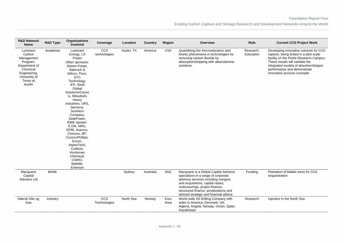
Foundation Report FourExisting Carbon Capture and Storage Research and Development Networks Around the World
Appendix 1 -55
R&D Network Name R&D Type Organisations
Involved Coverage Location Country Region Overview Role Current CCS Project Work
Luminant Carbon
Management Program,
Department of Chemical
Engineering, University of
Texas at Austin
Academia Luminant Energy, LS
Power Other sponsors: Alstom Power,
Babcock & Wilcox, Fluor,
GTC Technology, IFP, Shell
Global Solutions/Canso
lv, Mitsubishi Heavy
Industries, URS, Siemens, Southern Company,
SaskPower, RWE npower, E.ON, NRG,
EPRI, Aramco, Chevron, BP,
ConocoPhillips, Exxon,
AspenTech, Codexis,
Huntsman Chemical, CSIRO, Battelle, Emerson
CCS technologies
Austin, TX America USA Quantifying the thermodynamic and kinetic phenomena in technologies for removing carbon dioxide by absorption/stripping with alkanolamine solutions.
Research, Education
Developing innovative solvents for CO2 capture, being tested in a pilot scale facility on the Pickle Research Campus. These results will validate the integrated models of absorber/stripper performance and demonstrate innovative process concepts
Macquarie Capital
Advisers Ltd
BANK Sydney Australia ANZ Macquarie is a Global Capital Advisors specializes in a range of corporate advisory services including mergers and acquisitions, capital raises, restructurings, project finance, structured finance, privatizations and tailored strategic and financial advice.
Funding Plantation of Mallee trees for CO2 sequestration
Mærsk Olie og Gas
Industry CCS Technologies
North Sea Norway Euro Area
World wide Oil Drilling Company with sides in America, Denmark, UK, Algeria, Angola, Norway, Oman, Qatar; Kazakhstan
Research Injection in the North Sea

Foundation Report FourExisting Carbon Capture and Storage Research and Development Networks Around the World
Appendix 1 -56
R&D Network Name R&D Type Organisations
Involved Coverage Location Country Region Overview Role Current CCS Project Work
MAN Turbo Industry CCS technologies
Oberhausen Germany Euro Area
OEM of CO2 Compressors Technology supplier
Investigating options to reduce CO2 compression power.
Marine Ecology
Research Institute
Institute CCS technologies
Japan Japan Investigated how ocean sequestration of CO2 could affect surrounding seawater.
Research Presented a methodology to quantify impacts of elevated CO2 concentration on marine organisms using existing biological data
Massachusetts Institute of Technology
(MIT)
Academia CCS technologies,
Public Awareness
and Understanding
, Political Regional and Environmental
Issues
Cambridge, MA
America USA MIT Laboratory for Energy and the Environment (LFEE) is home to more than a dozen centres, groups and programs and serves as a focal point for energy and environmental activities. LFEE’s Carbon Capture and Sequestration Technologies (CCST) program looks at carbon management as a strategy to complement the current approaches to carbon mitigation.
Research, Education,
Policy Research
Studies of the economics of capture and sequestration, integrated assessment studies, research on a novel separation process, research on ocean carbon sequestration, and assessment of hydrogen storage materials. A major new component of the program is the Carbon Sequestration Initiative.; MIT developed the MIT Integrated Global System Model (IGSM), which is designed to simulate global environmental changes that may arise as a result of anthropogenic causes, the uncertainties associated with the projected changes, and the effect of proposed policies on such changes.
Massachusetts Institute of Technology
Energy Initiative (MITEI)
Academia Massachusetts Institute of
Technology under
government and industrial
sponsorship. See
http://web.mit.edu/mitei/ for more details.
CCS technologies; Regulations; Economics;
Public awareness
and understanding;
Information sharing; Political,
regional, and environmental
issues
Cambridge, MA
America USA Research on CCS is conducted throughout MIT by dozens of researchers. Some key organizations in this effort include MIT Carbon Capture & Sequestration Technologies Group (Howard Herzog), Department of Civil and Environmental Engineering (Ruben Juanes, Charles Harvey), Earth Resources Laboratory (Michael Fehler), Center for 21st Century Energy (Ahmed Ghoniem), Department of Chemical Engineering, and Center for Energy and Environmental Policy Research (John Parsons).
Research, education
Many – includes work on capture technologies (post-., pre-, and oxy-), reacting gas dynamics, geologic storage (modelling, monitoring), economic modelling, policy assessments, and development of regulatory regimes and business organizations.

Foundation Report FourExisting Carbon Capture and Storage Research and Development Networks Around the World
Appendix 1 -57
R&D Network Name R&D Type Organisations
Involved Coverage Location Country Region Overview Role Current CCS Project Work
McDonnell Academy
Global Energy and
Environment Partnership
Academia Bogazici University, Budapest
University of Technology and
Economics, China
Agricultural University,
Chulalongkorn University,
Fudan University,
Indian Institute of Technology,
Bombay, Interdisciplinary Centre Herzliya,
Jawaharlal Nehru
University, Korea
University, Middle East Technical University,
National Taiwan University, National
University of Singapore,
Peking University,
Seoul National University, State
University of Campinas, Tata
Institute of Social
Sciences, Technion—
Israel Institute of Technology, The Chinese University of Hong Kong,
Tsinghua University,
University of Chile, University of Hong Kong, University of
Information sharing
USA; Canada;
South America; Euro Area; East
Europe; Middle East;
Africa; Pacific Islands;
East Asia (ex.
Japan); Japan; China; India area; ANZ
Affiliated with the Consortium for Clean Coal Utilization
Research, education
The Consortium for Clean Coal Utilization will encourage collaborative research involving these university partners, including partners in China and India with major energy needs being met by coal.

Foundation Report FourExisting Carbon Capture and Storage Research and Development Networks Around the World
Appendix 1 -58
R&D Network Name R&D Type Organisations
Involved Coverage Location Country Region Overview Role Current CCS Project Work
McGill University
Academia Carbon Sense Solutions
CCS technologies
Quebec Canada Canada Investigating sequestration of CO2 by accelerated curing of concrete
Research, education
In certain industrial applications carbon dioxide can actually be used as a valuable feedstock. Carbon Sense Solutions Inc. has discovered and is developing a greenhouse gas mitigation technology, which consumes CO2 to manufacture more durable precast concrete products in far less time. The proof of concept phase was completed in 2006. Industrial pilot plant trials are ongoing throughout 2008.
McKinsey & Co.
Industry Economics Global USA Climate Change Special Initiative brings the latest insights, experience, and expertise from all parts of firm—including deep understanding of climate change; its implications for industries such as travel and logistics, biofuels, and financial services; and climate change strategy, low-carbon operations, low-carbon growth markets, and risk management.
Undertaken a multiyear research initiative to map the opportunities to reduce (or abate) greenhouse gas emissions. In 2007, completed a broad-based global study. More recently, taken a focused look at what can be done at a national level in a number of different countries. Developed these for the U.S., U.K., Germany, Australia, Netherlands, and Sweden, and are currently developing cost curves in a dozen other countries, including several emerging markets (e.g., India, China, Brazil).
Membrane Technology
and Research, Inc. (MTR)
Industry CCS technologies
Menlo Park, CA
America USA Dr. Merkel's recent work has focused on innovative membrane and module studies, including organic vapour transport in polymer/inorganic nanocomposites, novel water transport materials and devices, and membrane-based carbon capture from power plants.
Technology developer
Offers two innovations for CO2 capture using membranes: development of highly permeable polymer that readily permeates CO2 while offering good selectivity over N2 which would be applicable for post-combustion capture and use of the membrane in a novel process configuration that minimizes power consumption. MTR calculates energy penalty of process to be 12 percent for capture plus 6 percent for compression. Estimate membranes needed for a 600 MWe power plant would only occupy 0.5 acre footprint.

Foundation Report FourExisting Carbon Capture and Storage Research and Development Networks Around the World
Appendix 1 -59
R&D Network Name R&D Type Organisations
Involved Coverage Location Country Region Overview Role Current CCS Project Work
MIT Carbon Capture &
Sequestration Technologies
Group
Academia Massachusetts Institute of
Technology under
government and industrial
sponsorship, including an 18-
member industrial
consortium
CCS Technologies;
Political, regional and
environmental issues, Public
Awareness and
Understanding, Information
Sharing
Cambridge, MA
America USA Our research examines carbon sequestration from multiple perspectives, including technical, economic, and political. Current research interests include technology assessments, economic modelling, analysis of regulatory and political aspects, and development of a Carbon Management Geographic Information System (GIS). To complement our research, we have a strong commitment to stakeholder outreach and education. As such, we hold an annual Carbon Sequestration Forum each fall.
Research, education
Survey of public attitudes, representing CCS technologies in energy/economic models, assessment of policies to promote CCS innovation and deployment, modelling CCS power plants as part of the electricity grid, post-combustion capture for retrofits, feasibility of air capture, others. See http://sequestration.mit.edu/research/index.html for more details.
MIT Lab for Multiphase
Flow in Porous Media / Juanes
Research Group
Academia Massachusetts Institute of
Technology under
government and industrial
sponsorship, as well as private
donors and foundations
CCS Technologies
Cambridge, MA
America USA We study the physics of multiphase fluid flow in porous media. We apply our theoretical, computational and experimental research to a variety of energy-driven geophysical problems, such as geological carbon sequestration, methane hydrates, and petroleum recovery. We publish peer-reviewed papers, present our work at scientific conferences, collaborate with industry and government agencies, and engage with the press to disseminate our findings.
Research and education
(1) Development of mathematical models of capacity estimation at the geologic-basin scale. These models include the essential physics of CO2 migration and leakage, but are simple to apply and have only a few key parameters – therefore amenable to scoping studies, uncertainty quantification, and risk analysis. (2) Laboratory experiments and numerical simulation of unstable multiphase flows, with application to the migration and trapping of CO2 in saline aquifers.

Foundation Report FourExisting Carbon Capture and Storage Research and Development Networks Around the World
Appendix 1 -60
R&D Network Name R&D Type Organisations
Involved Coverage Location Country Region Overview Role Current CCS Project Work
Mitsubishi Heavy
Industries (MHI)
Industry CCS technologies
Japan Japan Developing the KS-1 technology a sterically-hindered amine solvent, for improved performance in post-combustion capture of CO2. Also developing a coal gasification process.
Manufacturer, supplier
MHI is conducting a feasibility for ZeroGen to evaluate the use of MHI's gasification technology in a proposed 400 MW IGCC+CCS plant. MHI is to build a Post-Combustion Capture pilot plant at an E.ON power station yet to be announced. This slip-stream plant will be operated on 440 m3/min (12,000 ACFM) flue gas. MHI has had an extensive development program that includes a 2-MW pilot plant processing coal-derived flue gas. The pilot plant built for E.ON will include many of the improvements identified experimentally and by supporting design studies. MHI is also supplying its KS-1 process for a 25 MW slipstream unit for a Southern Company coal-fired power plant in the USA.
Mitsui & Co Ltd Industry CCS Technologies
Tokyo Japan Japan Involved with the retrofit Callide Oxyfuel project at Biloela in Central Queensland (2010)
Mizuho Information &
Research Institute
Institute Political, regional and
environmental issues
Japan Japan political and environmental issues re CO2 sequestration
Policy research Conducted well-to-wheel analysis of greenhouse gas emissions of automotive fuels in the Japanese context; Also researched accounting rules on CO2 sequestration for national GHG inventories
Monash University
Academia CSIRO CCS technologies
Victoria Australia ANZ Investigating possibility of sequestering CO2 in deep coal seems. Developed a synthetic brown coal material and tested its reaction to CO2 pressures of 0.5 MPa, 1.0-1.5 Map (0.00002089-0.0000313 psf) .
Research, education
Study revealed a reduction in compressive peak strength of both synthetic coal samples and natural brown coal samples with an increase in saturation gas pressure and saturation duration.

Foundation Report FourExisting Carbon Capture and Storage Research and Development Networks Around the World
Appendix 1 -61
R&D Network Name R&D Type Organisations
Involved Coverage Location Country Region Overview Role Current CCS Project Work
Monitor Scientific LLC
Industry CCS technologies,
Public Awareness
and Understanding
Denver, CO America USA A science and engineering consultancy that provides technical support to its clients in the areas of environmental, assessment, remediation evaluation, and waste management.
Consultant Research Provider in Phase 1 of the IEA Weyburn CO2 Monitoring and Storage Project; Conducted risk assessments using a methodology involving systems analysis similar to that used in the geological disposal of nuclear waste, together with a hybrid of probabilistic and deterministic simulations of CO2 migration along natural and man-made pathways, followed by environmental consequence analysis.
Montana State University
Academia CCS technologies
Bozeman, MT
America USA Project Manager for the Big Sky Carbon Sequestration Partnership.
Research, Education
Faculty, staff and students from MSU will be involved in aspects of the Big Sky Regional Sequestration Partnership project ranging from education to project management to geochemistry.
Monterey Bay Aquarium Research Institute
Institute CCS technologies
Monterey, CA
America USA Investigating ocean storage of CO2 Research Studying ocean chemistry of greenhouse gases, including ocean sequestration of CO2
National Carbon Capture Center
Government
US DOE, Southern Company,
EPRI, Luminant, Peabody
Energy, AEP, Arch Coal, Rio
Tinto
CCS technologies
Wilsonville, AL
America USA Public-private partnership will focus on developing technologies to reduce greenhouse gas emissions from coal-based electricity generation
Research Once fully operational in 2010, the National Carbon Capture Centre will bring together science and innovation in technology development, along with real-world testing capability, to play a leading role in the effort to achieve cost-effective and reliable capture of carbon dioxide from coal-based power generation.

Foundation Report FourExisting Carbon Capture and Storage Research and Development Networks Around the World
Appendix 1 -62
R&D Network Name R&D Type Organisations
Involved Coverage Location Country Region Overview Role Current CCS Project Work
National Institute of
Standards & Technology
(NIST)
Government
Thermophysical Properties Division, National
Institute of Standards and
Technology (NIST)
CCS technologies
Boulder, CO America USA NIST’s mission is to promote U.S. innovation and industrial competitiveness by advancing measurement science, standards, and technology in ways that enhance economic security and improve our quality of life. NIST’s Thermophysical Properties Division strives to be the foremost and best source of high-quality thermophysical property information. This vision is driven by the ubiquitous importance of this information to commerce, industry, manufacturing, and national policy objectives. The Division meets its challenges through an integrated program of experimental measurement, data collection and evaluation, development of theoretically based models, and simulation of model systems. Among the outputs of the Division are computerized standard reference databases which synthesize thermophysical property information in forms which are conveniently used by our stakeholders.
Research, Data Dissemination
The molecular thermodynamic framework designed above is being extended to include the interaction of water with carbon dioxide, which is important for synthesis gases, for combustion gases, and for compression of CO2-rich gas streams. High-temperature PVT experiments on water-nitrogen and water-CO2 mixtures are underway to validate the molecular modeling. These data will be integrated with a version of NIST’s Refprop program to provide accurate thermodynamic models for gaseous mixtures containing water up to high temperatures. Thermal conductivity data are also being measured at high temperatures for water-nitrogen and water-CO2 mixtures; these data can contribute to improved modeling of heat transfer in combustion gases. We are also participating in a project (led by a group at the Ruhr University of Bochum, Germany) to develop a comprehensive model (including vapor-liquid equilibrium) for the water-CO2 mixture that can be used to predict thermodynamic behaviour (including condensation) during compression.
National Taiwan
University
Academia CCS technologies,
Public Awareness
and Understanding, Information
Sharing
Taipei, Taiwan
Taiwan East Asia (ex.
Japan)
CO2 can be converted to hydrocarbons via photo reduction using photocatalyst, that is, mimic to photosynthesis. Such route has the advantages of both renewable energy and CO2 remedy.
TiO2 and Cu/TiO2 were synthesized by a sol-gel method using a homogeneous hydrolysis technique. The photocatalytic reduction of CO2 was performed in aqueous solution. Major hydrocarbon product was methanol, which can be use as fuel or raw chemicals. The photocatalytic efficiency of Cu/TiO2 was significantly increased because of lowering the re-combination probability of hole-electron pairs. Characterization of Cu/TiO2 indicated that Cu+ was active site, and an optimum Cu loading/dispersion was required to give maximum methanol yield.

Foundation Report FourExisting Carbon Capture and Storage Research and Development Networks Around the World
Appendix 1 -63
R&D Network Name R&D Type Organisations
Involved Coverage Location Country Region Overview Role Current CCS Project Work
Natural Resources Defense Council (NRDC)
Institute Regulations, Public
Awareness and
Understanding, Political
Regional and Environmental
Issues
America USA Environmental action group; use law, science and support of its members to protect the planet's wildlife and wild places to ensure a safe and healthy environment
Policy Research,
Public Outreach,
Policy Advocacy, Litigation
Researching and advocating for public policy and regulatory options which would ensure that CCS contributes to the timely reduction of anthropogenic CO2 emissions, and that the technology is applied in a safe, effective and environmentally sound manner. Public outreach and education on the nature and efficacy of the technology. Press outreach.
Netherlands Environmental Assessment
Agency
Government
JRC-IES, Ispra Information sharing, Political
Regional and Environmental
Issues
Netherlands
Euro Area
Compiles and stores global emission inventories of direct and indirect greenhouse gases from anthropogenic sources including halocarbons and aerosols both on a per country and region basis as well as on a grid.
Information sharing, public outreach, policy
research
Currently updating the data in EDGAR for more recent years and to include additional compounds such as aerosols. Have started a new so-called Fast Track action to estimate recent global emissions at country and grid level based on readily available data. Moreover, the collaborating institutes will further enhance the website and aim at shifting the gridded datasets to a higher resolution of 0.5 by 0.5 degree

Foundation Report FourExisting Carbon Capture and Storage Research and Development Networks Around the World
Appendix 1 -64
R&D Network Name R&D Type Organisations
Involved Coverage Location Country Region Overview Role Current CCS Project Work
Netherlands organisation for Applied Scientific Research
(TNO)
Government
CCS technologies
Netherlands
Euro Area
focuses on new methods for extracting minerals, energy use in the built-up environment, new energy sources for mobility, energy efficiency in industry, climate change, CO2 storage and the development of new heating sources. CCS is an important topic for TNO, the largest fully independent non-profit research organisation in the Netherlands (4,500 employees). TNO covers the whole chain of CCS from generation up to storage.
Research As part of the CATO project, TNO and E.ON Benelux have built the CO2 Catcher pilot plant at the 2 x 550-MW coal-fired Maasvlakte plant near Rotterdam. The 20-m3/min (710-ACFM) flue gas slip-stream is drawn from one plant after the FGD unit. The aim of the pilot plant is testing and validating absorption liquids and membrane contactors. The initial absorption liquid tested will be CORAL, an amino acid salt developed by TNO, and other solvents will be tested as they become available. This work will be carried out primarily using a conventional absorber design but a by-pass is provided allowing membrane contactors to be installed and tested. These are more compact with a lower capital cost. The test facility commenced operation in April 2008 and the program will last for at least two years. In February 2009 it was reported that the pilot plant had operated for more than 3,000 hours and captured over 750 tonnes (827 tons) of CO2.

Foundation Report FourExisting Carbon Capture and Storage Research and Development Networks Around the World
Appendix 1 -65
R&D Network Name R&D Type Organisations
Involved Coverage Location Country Region Overview Role Current CCS Project Work
NETL Big Sky Regional Carbon
Sequestration Partnership (Big Sky)
Government
Montana State University; Lawrence Livermore National
Laboratory; Los Alamos National
Laboratory; University of Washington
CCS technologies,
Public Awareness
and Understanding, Information
Sharing
North West States
America USA A three phase process to evaluate and demonstrate sequestration in the region
Research, Demonstration,
Information Sharing, public
outreach
Assess the relative efficiency of alternative sequestration options, prove the environmental efficacy and sustainability of sequestration, verify regional CO2 sequestration capacities, and satisfy field test permitting and regulatory requirements preparing to inject approximately 907 tonnes (1,000 tons) of supercritical CO2 into a deep basalt formation in eastern Washington state in 2009. A larger demonstration project will be located at Riley Ridge in southwest Wyoming. It will inject up to 0.9 million tonnes (992,080 tons) per year of a mixture consisting of CO2 (92%) and H2S (8%) recovered from the Cimarex natural gas processing plant. The injection will be in a saline reservoir at the 3350 m (11,000 foot) level of the Nugget (Eolian) sandstone formation. Current plans call for the injection to begin in September 2011 and to continue for three years. Monitoring and verification activities will continue through 2016.
NETL Midwest Geological
Sequestration Consortium
(MGSC)
Government
Illinois State Geological
Survey; Battelle Memorial
Laboratories; Illinois, Indiana and Kentucky State Geologic Surveys; Archer Daniels Midland
(ADM) Schlumberger
Carbon Services
CCS technologies
Midwest States
America USA A three phase process to evaluate sequestration. Assess and validate aspects of geological CO2 storage in the Illinois Basin. Continue investigation into the methods and economics of CO2 capture at facilities such as coal-fired power plants. Examine the costs of transporting large quantities of CO2 via pipeline. Develop monitoring, verification, and accounting protocols to ensure safe and effective sequestration operations.
Research, Demonstration,
Information Sharing, public
outreach
Testing the viability of multiple geological storage options. Demonstration project t is located in Decatur, Illinois and will inject 1 million tonnes of >99% pure CO2, captured at an Archer Daniels Midland (ADM) ethanol fermentation plant, at a depth of a depth of over 1520 m (5000 feet) into the Mount Simon sandstone saline formation that underlies the ADM plant. Injection started in Feb. 2009 and will continue for 3 years.

Foundation Report FourExisting Carbon Capture and Storage Research and Development Networks Around the World
Appendix 1 -66
R&D Network Name R&D Type Organisations
Involved Coverage Location Country Region Overview Role Current CCS Project Work
NETL Midwest Regional Carbon
Sequestration Partnership (MRCSP)
Government
Battelle Memorial Institute
CCS technologies,
Public Awareness
and Understanding
, Political Regional and Environmental
Issues, Information
Sharing
Northeastern States
America USA A three phase process to evaluate sequestration: Identify, characterize, and map greenhouse gas sources and assess the viability and cost of capturing and sequestering emissions Engage public and elected officials at all levels in dialogue on issues affecting implementation of sequestration and identifying factors that might contribute to enhanced public acceptance of sequestration technologies. Validate the potential for implementation of geological sequestration in the region by first conducting three small-scale CO2 injection field tests into selected deep geologic reservoirs to demonstrate the safety and effectiveness of geologic sequestration systems.
Research, Demonstration,
Information Sharing, public
outreach
A large scale CO2 storage demonstration is planned at The Andersons Marathon Ethanol, LLC (TAME) fermentation plant located in Greenville, Ohio. The demonstration will involve injection of >97% pure CO2 produced in TAME plant into saline in the Mount Simon Sandstone formation at a depth of between 1000m (3300 ft) and 1100 m (3600 ft). Injection start is planned for June 2010. The planned duration of injection is 4 years and a total of 1 million tonnes (1.1 million tons) of CO2 will be stored.

Foundation Report FourExisting Carbon Capture and Storage Research and Development Networks Around the World
Appendix 1 -67
R&D Network Name R&D Type Organisations
Involved Coverage Location Country Region Overview Role Current CCS Project Work
NETL Plains CO2
Reduction Partnership
(PCOR)
Government
University of North Dakota
Energy & Environmental
Research Centre
CCS technologies,
Public Awareness
and Understanding
North Central states
America USA A three phase process to evaluate sequestration: - Continuing to assess regional carbon sequestration opportunities. - Developing field tests. - Evaluating selected commercial-scale carbon sequestration technologies. - Assessing CO2 storage resource, economics, and public benefits. - Providing outreach and education about CO2 sequestration. A. Provide insight on the effects of H2S on formation integrity including seal degradation, MVA techniques and EOR success that can be used in the subsequent Fort Nelson Development Project B. Provide preliminary information that can be used in the subsequent Williston Basin Development Project C. Provide information on CO2 sequestration and ECBM recovery from unmineable coal seams. D. Verify and validate the technical and economic feasibility of using brine-saturated carbonate formations for large scale CO2 injection. Demonstrate that robust MMV can be conducted cost-effectively.
Research, Demonstration,
Information Sharing, public
outreach
PCOR intends to conduct two storage demonstrations: one into a saline formation and one into an oil field for enhanced oil recovery (EOR). The saline storage demonstration in PCOR will inject 1 million tonnes (1.1 million tons) of acid gas (85% CO2/15% H2S) captured from a natural gas processing facility into Elk Point Rock formation at a depth of 2000 m (6500 feet) in northeast British Columbia. Injection is planned to begin in September 2010. The EOR project will be located in North Dakota. 500,000 tonnes (551,155 tons) per year recovered from the Antelope Valley lignite-fired power plant of Basin Electric will be transported 240 km (150 miles) to the Williston Basin and injected at 3,050 m (10,000 feet) into the pore spaces of an oil reservoir. Injection is to start in December 2012. Basin Electric has selected Powerspan’s ECO2 CO2 capture process for the Antelope Valley plant, and the capture project was recently awarded $100 million USD in “round 3” of the US Dept of Energy’s Clean Coal Power Initiative.

Foundation Report FourExisting Carbon Capture and Storage Research and Development Networks Around the World
Appendix 1 -68
R&D Network Name R&D Type Organisations
Involved Coverage Location Country Region Overview Role Current CCS Project Work
NETL Southeast Regional Carbon
Sequestration Partnership (SECARB)
Government
Southern States Energy Board
CCS technologies
Southeast States
America USA A three phase process to evaluate sequestration. The “stacked formations”, oil fields overlying deep saline reservoirs, along the Gulf Coast, and more specifically in the states of Alabama, Florida, Louisiana, Mississippi, and Texas, are a prime target area for geologic CO2 storage
Research, Demonstration,
Information Sharing, public
outreach
SECARB has plans to conduct two storage demonstrations; both into saline reservoirs in the Lower Tuscaloosa Formation – a massive formation that has the potential to store a thousand years of the SECARB region’s man-made CO2 emissions. The first demonstration will use naturally-occurring CO2 from the Jackson Dome in central Mississippi. The CO2 will be transported by pipeline to a site 24 km (15 miles) east of Natchez, Mississippi and injected into the down-dip saline water leg of the local oil field (Cranfield site). A total of 1.5 million tonnes (1653467 tons) will be injected over 18 months. The injection began in April 2009. The second demonstration will use CO2 captured from a coal-fired power plant near Mobile, Alabama owned by Alabama Power Company (Plant Barry). The CO2 will be injected approximately 16 km (10 miles) away at the 2950 m (9000 ft.) level of the Lower Tuscaloosa part of the Gulf Coast Wedge formation in the Citronelle oil field which is owned and operated by Denbury Resources.
NETL Southwest Regional
Partnership on Carbon
Sequestration (SWP)
Government
New Mexico Institute of Mining and Technology
CCS technologies,
Public Awareness
and Understanding, Information
Sharing
Southwest States
America USA A three phase process to evaluate sequestration. Deep saline formations: over 88 billion tonnes (8818490490 tons) of CO2 capacity. Abandoned and depleted oil and natural gas reservoirs: over 21 billion tonnes (23.1 billion tons) of CO2 capacity. Coal seams: almost a billion tonnes of CO2 capacity.
Research, Demonstration,
Information Sharing, public
outreach
SWP is planning a storage demonstration located near Prince, Utah in the Uinta Basin in central Utah. A total of 2 million tonnes (2.2 million tons) of naturally occurring CO2 will be injected at rates up to 1 million tonnes (1.1 million tons) per year beginning in June 2010. The injection target is a saline reservoir in the deep Jurassic age sandstone overlain by shale.

Foundation Report FourExisting Carbon Capture and Storage Research and Development Networks Around the World
Appendix 1 -69
R&D Network Name R&D Type Organisations
Involved Coverage Location Country Region Overview Role Current CCS Project Work
NETL West Coast
Regional Carbon
Sequestration Partnership
(WESTCARB)
Government
California Energy
Commission; Lawrence Berkeley National
Laboratories; Simulations
Sandia Technologies
LLC
CCS technologies
Western States
America USA Demonstrate the feasibility, safety, and efficacy of promising geologic and terrestrial carbon sequestration solutions, which include storage in depleting gas reservoirs, saline formations, and unmineable coal seams, as well as various land management techniques
Research, Demonstration,
Information Sharing, public
outreach
A three phase process to evaluate sequestration: Conduct pilot tests to validate carbon storage technologies in the region; Refine and enhance the broad regional evaluation of carbon sequestration potential; Identify opportunities for a large-scale CO2 storage test in the region; Seeking community input on issues surrounding pilot-scale and commercial-scale sequestration project development; Technology discussions, regional meetings, and joint research will be used to maintain an open dialogue with regional stakeholders.WESTCARB’s storage demonstration project is based on injection of CO2 recovered from the 50 MWe Clean Energy Systems oxyfuel power plant at Kimberlina in the Central Valley of California. The injection is targeted for one selected saline layer of the 2130 m (7000 foot) deep Vedder sandstone geologic formation which underlies the plant. The CO2 would be injected at a rate of 227,000 tonnes (250,224 tons) per year for four years. Injection start is planned for September 2012.
New Jersey Institute of Technology
Institute Newark, NJ America USA Research Researchers propose a pressure swing absorption approach to capture CO2 using an ionic liquid incorporated in either a ceramic hollow tube or polytetrafluoroethylene (PTFE) fibre membrane (DOE share: $805,819; recipient share: $206,017; duration: 36 months).
New Mexico Institute of Mining and Technology
Academia SWP CCS technologies
NM America USA Project Manager for the Southwest Regional Partnership on Carbon Sequestration
Project Manager for the Southwest Regional Partnership on Carbon Sequestration

Foundation Report FourExisting Carbon Capture and Storage Research and Development Networks Around the World
Appendix 1 -70
R&D Network Name R&D Type Organisations
Involved Coverage Location Country Region Overview Role Current CCS Project Work
Newcastle University
Academia CCS technologies
Newcastle upon Tyne, Tyne and
Wear
UK Euro Area
Leads the 13-university EPSRC ‘SUPERGEN: Delivery of Sustainable Hydrogen’ consortium; much of this work involves integration with carbon capture processes
Research Highly energy-efficient method of converting CO2 into chemical compounds known as cyclic carbonates.
Norwegian University of Science and Technology
(NTNU)
Academia SINTEF; Aker Clean Carbon
CCS technologies
Trondheim Norway Euro Area
In August 2008, NTNU, SINTEF and Aker Clean Carbon signed an agreement for an eight-year science and development programme called SOLVit.
The programme includes building a new laboratory at Tiller in Trondheim. The lab will be a unique test centre for pilot projects, including a 30 metre tall tower and processing column that reached 25 metres high – identical to the height needed in full-scale industrial facilities.
Nuon CO2 Capture Pilot Programme
Industry Nuon, Energy Research
Centre of the Netherlands (ECN), TNO,
Delft University Technology,
KEMA
CCS technologies
Buggenum Netherlands
Euro Area
The project consists of several phases: 1) basic design of the plant for a large scale application in Nuon Magnum plant, 2) basic and detailed design for a scale-down version of the plant (pilot) to be tested at a slip-stream in Buggenum Willem-Alexander Power Plant, 3) pilot plant construction, 4) pilot plant operation, R&D programme execution, result gathering, 5) results implementation in a large scale Nuon Magnum plant.
Research, Project
Development, Operation,
Result Implementation
Construction began in July 2009 on the pilot plant. Testing is expected to begin in forth quarter of 2010 and continue for 2 years.
Ohio Coal Development
Office (OCDO)
Government
CCS technologies
OH America USA Co-funds the development and implementation of technologies that can use Ohio’s vast reserves of high-sulphur coal in an economical, environmentally sound manner.
Funder Midwest Regional Carbon Sequestration Partnership Demonstration Plan for CO2 Sequestration CO2-Brine-Rock reactions for carbon sequestration in Ohio's deep saline aquifers Revegetation of Reclaimed Mineland for Soil Carbon Sequestration and Biofuel Production
Ohio State University
Academia CCS technologies
OH America USA Prof. Fan developed an adsorption-based process to capture CO2. In this process, calcium oxide reacts with CO2 to form calcium carbonate.
Research, education
The technology has been tested at bench scales at low CO2 removal rates. Tests for higher removal rates have not been conducted.

Foundation Report FourExisting Carbon Capture and Storage Research and Development Networks Around the World
Appendix 1 -71
R&D Network Name R&D Type Organisations
Involved Coverage Location Country Region Overview Role Current CCS Project Work
Pacific Northwest National
Laboratory
Government
Battelle, US Dept of Energy
CCS technologies
Richland, WA
America USA Developing a new class of materials for CO2 capture that aims to significantly reduce the energy penalty for CO2 capture.
The PNNL capture process does not require dramatic pressure and temperature swings, making it more energy-efficient. And the concept integrates CO2 capture with a water-gas shift reaction into a single, more efficient unit, reducing costs and creating a near-zero emissions system. Integrating the process improves the efficiency of the water-gas shift reaction, which converts carbon monoxide to CO2 and hydrogen by reacting with water vapour, ultimately producing more CO2 and more hydrogen, the desired product.
Pall Corp. Industry CCS technologies
New York, NY
America USA Parts Manufacturer DOE 2009 Fossil Energy Techline
Parsons Brinckerhoff
Industry UK government and Xstrata
Coal Company, Queensland,
CCS Technologies
Many International
USA; Canada;
South America; Euro Area; East
Europe; Middle East;
Africa; Pacific Islands;
East Asia (ex.
Japan); Japan; China; India area; ANZ
Provides strategic consulting, planning, engineering, and program and construction management services.
Engineering, Procurement, Construction
Technical advisor to the UK Government for CCS demonstration projects. Completed environmental impact assessment for the Wandoan IGCC + CCS project in Queensland Australia
Peabody Energy
Corporation
Industry CCS technologies
MO America USA Founding member of the U.S. Department of Energy (DOE) National Carbon Capture Center and a member of the FutureGen Alliance and the Chinese GreenGen project.
Funder, project developer
Only non-Chinese equity partner in GreenGen, China's centerpiece climate initiative; A founding member in the COAL21 Fund in Australia.

Foundation Report FourExisting Carbon Capture and Storage Research and Development Networks Around the World
Appendix 1 -72
R&D Network Name R&D Type Organisations
Involved Coverage Location Country Region Overview Role Current CCS Project Work
Penn State University
Academia CCS technologies,
Public Awareness
and Understanding
PA America USA Investigating the use of microbes to take electricity and convert CO2 and water to methane, producing a portable energy source with a potentially neutral carbon footprint.
Research, education
Microbial electrolysis cells do require an electrical voltage to be added to the voltage that is produced by bacteria using organic materials to produce current that evolves into hydrogen. The researchers found that the Archaea, using about the same electrical input, could use the current to convert carbon dioxide and water to methane without any organic material, bacteria or hydrogen usually found in microbial electrolysis cells. They report their findings in a March/April 2009 issue of Environmental Science and Technology.
Petroleo Brasileiro S.A.
(Petrobras)
Industry Economics, Public
awareness and
understanding
Brazil South America
The Pontifical Catholic University of Brazil, and Brazil oil company Petrobras, have teamed up to create the Energy and Carbon Storage Research Centre in Porto Alegra, Brazil, according to an article released by the US State Department
Public outreach Focusing on public perception and acceptance of carbon capture and storage, and working out ways to make it commercial.
Petroleum Technology Research
Centre
Institute CCS technologies
Regina Canada Canada Developing enhanced oil recovery and CO2 storage technologies
Research 1) Managing of the world's largest CO2 Storage Project (Weyburn-Midale CO2 Project); 2) Managing potentially the world's largest avoided CO2 emissions project (JIVE Project); 3) Collaborating with SaskPower on the world's first zero emissions coal fired power plant; 4) Advancing enhanced oil recovery technologies (EOR Research Program)
Pew Centre Institute Public awareness
and understanding
America USA Brings together business leaders, policy makers, scientists, and other experts to bring a new approach to a complex and often controversial issue.
Public outreach Produces analyses of key climate issues; working to keep policy makers informed; engaging the business community in the search for solutions; reaching out to educate key audiences.

Foundation Report FourExisting Carbon Capture and Storage Research and Development Networks Around the World
Appendix 1 -73
R&D Network Name R&D Type Organisations
Involved Coverage Location Country Region Overview Role Current CCS Project Work
Pipeline Research Council
International
Industry See list of over 50 members at: http://prci.org/index.php/site/me
mbership/
CCS Technology
Arlington, VA
America USA community of pipeline companies, and the vendors, service providers, equipment manufacturers, and other organisations supporting the industry
Research Guidelines for various transport issues, such as Mitigation SCC Susceptibility Evaluations, soil evaluations
Polish Academy of
Sciences
Institute CCS technologies
Poland East Europe
PAN as a research centre is currently comprised of 79 research establishments and auxiliary scientific units. The research activity of the Academy is financed mainly from the State budget via the Ministry of Science and Higher Education.
Research Working on separation of gaseous mixtures using adsorption and membrane methods
Politecnico di Milano
Academia CCS technologies
Milan Italy Euro Area
Researching the production of “zero emission” electricity and hydrogen from fossil fuels (natural gas, coal, heavy and residual fuels).
Research, education
Performance assessment of production processes based on pre-combustion, post-combustion and oxygen combustion techniques. Developed software that can reliably predict the performance of conventional power stations; has been applied to evaluate thermal balances of low CO2 emission plants based on commercially ready technologies as well as plants based on novel equipments such as hydrogen separation membrane reactors, oxygen transport membranes and closed loop combustors.
Potsdam Institute for
Climate Impact Research
Institute Regulations, Public
Awareness and
Understanding
Potsdam Germany Euro Area
Addresses crucial scientific questions in the fields of global change, climate impacts and sustainable development. Generates interdisciplinary insights and provides society with sound information for decision making.
Research, public outreach
Developing climate policy scenarios that imply the current knowledge about the Earth system’s determining components and that represent win-win solutions to stakeholders; Developing software tools that provide and support climate policy scenario analyses
PowerSpan Industry US DOE CCS technologies
NH America USA Developing and commercializing proprietary, multi-pollutant control and post-combustion carbon dioxide (CO2) capture technology for electric power plants
Technology developer, technology
supplier
Construction began in 2007 on a 1.0 MW ECO2 pilot plant at the FirstEnergy Burger Plant, which will be sized for 90 percent CO2 capture. This plant began operation in late 2008.

Foundation Report FourExisting Carbon Capture and Storage Research and Development Networks Around the World
Appendix 1 -74
R&D Network Name R&D Type Organisations
Involved Coverage Location Country Region Overview Role Current CCS Project Work
Praxair Industry Jamestown Board of Public
Utilities; Dresser-Rand;
Foster Wheeler; Battelle
Memorial Institute
CCS technologies
NY America USA Involved with oxy-combustion development
Technology developer, technology
supplier
In July 2007, Praxair announced it would participate in an engineering study about the application of Praxair's oxy-coal technology to a power-generation project in Jamestown, New York.
Princeton Environmental
Institute, Carbon
Mitigation Initiative
Academia BP; Ford Motor Company
CCS technologies
NJ America USA Joint project of Princeton University, BP, and the Ford Motor Company to find solutions to the global warming problem
Research Focusing on four areas: carbon capture, carbon storage, carbon science, and carbon policy
Process Group Pty Ltd
Industry CCS Technologies
Melbourne; Abu Dhabi
Australia; UAE
ANZ; Middle East
supplier of packaged process systems and process trains for the Oil & Gas production, refining, petrochemical & Carbon Capture Industries.
Research, Development
CO2CRC Nirranda South, Victoria CO2 Geosequestration Package (2008) Cool Energy Perth Basin, Western Australia CryoCell® Demonstration Package (2005)
Purdue University
Discovery Park Energy Centre
Academia CCS technologies
IN America USA Focuses on technologies for converting coal into combustible gases and liquids that can be cleanly burned to meet the exploding demand for electric power ~ heating and transportation
Researchers at the Energy Centre are developing ways to utilize the nation’s coal resources in a manner that produces near zero emissions and promotes acceptable environmental standards.
Quintessa Ltd Industry Mitsubishi Materials Corp;
Research Institute of Innovative
Technology for the Earth; Central
Research Institute of
Electric Power Industry
CCS technologies
UK Euro Area
Investigating any advantages of sequestering CO2 in high temperature areas, where reactions between CO2-charged water and rock will be more rapid.
Research Provides numerical modelling support investigating the feasibility of CO2 sequestration in geothermal areas.

Foundation Report FourExisting Carbon Capture and Storage Research and Development Networks Around the World
Appendix 1 -75
R&D Network Name R&D Type Organisations
Involved Coverage Location Country Region Overview Role Current CCS Project Work
RamGen Power
Systems
Industry Ramgen Power Systems,
Dresser-Rand, National Energy Technology Lab
(NETL)
CCS technologies
11808 Northup
Way, Suite W-190;
Bellevue, WA
America USA Ramgen Power Systems, Inc. is developing a family of high performance CO2 compressors that combine many of the aspects of shock compression systems, commonly used in supersonic flight inlets, with turbo-machinery design practices employed in conventional axial and centrifugal compressor design. Shock wave compression technology has the potential to develop very high compression ratio per stage and very high efficiency, simultaneously. This capability allows Ramgen to configure a 2-stage CO2 compressor for a pressure ratio of 100+:1, while conventional technology will typically require 8-stages of compression. The input power to Ramgen’s 2-stage intercooled compressor will be comparable to the 8-stage conventional approaches, but the individual compressor stage discharge temperature will be 450-500°F vs. the conventional 8-stage 200°F, allowing for cost effective heat recovery of at least 80% of the input Btu. The all-in capital cost is expected to be 50-60% of the conventional approaches.
Technology developer
Applying supersonic flight inlet concepts and methods to ground-based air and gas compression applications

Foundation Report FourExisting Carbon Capture and Storage Research and Development Networks Around the World
Appendix 1 -76
R&D Network Name R&D Type Organisations
Involved Coverage Location Country Region Overview Role Current CCS Project Work
Reacting Gas Dynamics/Cent
er for 21st Century
Energy at MIT
Academic Massachusetts Institute of
Technology, work sponsored by government, industrial and
other academic organizations, domestic and international.
CCS Technologies
Cambridge, MA
America USA Research on high efficiency, low-carbon energy from hydrocarbons, hybridizing with biomass and concentrated solar thermal energy, through thermochemical conversion and combustion. We develop, validate and apply multiphysics multiscale simulation techniques, from the submicron scale to the system’s scale, to engineer optimal, clean, low CO2-energy systems based on sound fundamental understanding of the underlying mechanisms. Innovations in: clean combustion for propulsion and power, gasification for power and biofuel production, and oxy-combustion and electrothermochemical conversion in ion-transport membrane reactors and high-temperature fuel cells for CO2 capture.
Research and education
Multiscale analysis and experimental validation of several CO2 capture key technologies including gasification of solid fuels, oxy-combustion of solid and gaseous fuels, and electrothermochemical conversion in ion-transport membrane reactors and high-temperature fuel cells.
Reaction Engineering
Intl
Industry CCS technologies
Salt Lake City, UT
America USA Investigating oxy-combustion via modelling.
Research REI will conduct multi-scale experiments, coupled with mechanism development and computational fluid dynamics modelling, to elucidate the impacts of retrofitting existing coal-fired utility boilers for oxycombustion. Test data will be obtained from oxycombustion experiments at 0.1 kilowatt, 100 kilowatt and 1.2 megawatt scale. (DOE share: $2,376,443; recipient share: $617,767; duration: 36 months)
Recycle CO2 (RCO2) Inc.
Industry CCS technologies
Kingsport, TN
America USA Investigating the recycling of CO2 produced from hydrocarbon combustion
Research Developing catalytic CO2 recycle technology. CO2 is catalytically converted to two useful products-methane and water. Oxygen is also generated in this process. The methane produced can be used to generate electricity. This is an energy efficient process for the recycling of CO2. This process consists of three chemical reactions; the combustion of methane, the splitting of water, and the hydrogenation of CO2.

Foundation Report FourExisting Carbon Capture and Storage Research and Development Networks Around the World
Appendix 1 -77
R&D Network Name R&D Type Organisations
Involved Coverage Location Country Region Overview Role Current CCS Project Work
Research Institute of Innovative
Technology for the Earth (RITE)
Institute In 2006, NTNU signed MOU to collaborate on CO2 capture technologies
CCS technologies
Kyoto Japan Japan RITE is non-profit research organisation developing technologies that mitigate global warming. Established extensive global network.
Research Studying 3 methods of CO2 separation from effluent gas, that is, absorption by organic base solution, separation by polymer membrane and adsorption by inorganic porous materials. Also studying CO2 storage options.
ResourcesLaw International
Associates Pty Ltd
Regulations Sydney Australia ANZ A consulting firm specialising in the energy and natural resources industries which has been involved in many groundbreaking projects in Australia and the Asia-Pacific region and has often acted as a consultant to the APEC Secretariat in Singapore on cross-border energy trade.
Advising
Rio Tinto Ltd Industry Rio Tinto Ltd (AUS)
Rio Tinto Plc (UK)
CCS technologies, Regulations, Economics,
Public awareness
and understanding,
Information sharing
HQ: London UK; Global
USA; Canada;
South America; Euro Area; East
Europe; Middle East;
Africa; Pacific Islands;
East Asia (ex.
Japan); Japan; China; India area; ANZ
Rio Tinto’s business is finding, mining and processing mineral resources including Coal.
Funder, Project Developer, Technology Developer
It has contributed resources and investment funds to the FutureGen clean coal research project in the US, COAL21 in Australia and to the International Energy Agency’s Clean Coal Centre. IGCC joint venture with BP (see hydrogen energy), Oxyfuel interests but no technical ventures established as yet. Developed the Hismelt process for direct reduction of iron which can be readily adapted to capture CO2.
RIST Industry CCS technologies
Korea East Asia (ex.
Japan)
Investigating solvents for post-combustion capture
Research Investigating use of aqueous ammonia for CO2 capture

Foundation Report FourExisting Carbon Capture and Storage Research and Development Networks Around the World
Appendix 1 -78
R&D Network Name R&D Type Organisations
Involved Coverage Location Country Region Overview Role Current CCS Project Work
Rolls-Royce Industry UK Government's Technology
Strategy Board, Engineering and
Physical Sciences Research
Council, plus undefined regional partners
CCS technologies
Sites include the
Advanced Manufacturing Research
Centre in Sheffield (founder member
Boeing), the Advanced Forming
Research Centre at
Strathclyde University,
and the Centre for Aerospace Propulsion Systems
with University of Virginia and
Virginia Tech.
UK Euro Area
Development of low carbon aircraft engine technologies. Rolls-Royce also provides gas turbines for power generation. The aero technology could be transferred to power generation and pipeline compressor applications.
Technology developer, technology supplier,
Rolls-Royce is currently developing a new aerospace manufacturing facility in Virginia, one site that will manufacture the more efficient engines.
Royal Belgian Institute of
Natural Sciences
Institute CCS technologies
Brussels Belgium Euro Area
Part of the Policy Support System for Carbon Capture and Storage “PSS-CCS”
Developing a tool capable of projecting the implementation of CCS in a Belgian context. With this simulator, will develop a series of databases on the three main elements in the CCS chain: capture, transport and storage.

Foundation Report FourExisting Carbon Capture and Storage Research and Development Networks Around the World
Appendix 1 -79
R&D Network Name R&D Type Organisations
Involved Coverage Location Country Region Overview Role Current CCS Project Work
Royal Belgian Institute of
Natural Sciences – Geological Survey of Belgium
Government
CCS technologies,
Public Awareness
and Understanding
, Political Regional and Environmental
Issues
Belgium Euro Area
The goal of the project 'Policy Support for Carbon Capture and Storage' is to stimulate the introduction and growth of Carbon Capture and Storage as an economic activity in Belgium.
Policy Research, technical research, education
Launching two new projects: The PSS-CCS BeNe project is a valorisation project aimed at a cooperation with the Dutch partner Ecofys. This project will allow integration CCS data from the Netherlands in a simulator, which will result in CCS simulations in a truly international context; The PSS-CCS II project is the follow-up project of PSS-CCS (I). With the previous project, the simulator has proven its capabilities. Now the databases and scenario definitions will be updated, in order to run simulations that are as close to reality as possible.
RTI International
Institute Louisiana State University; Church and
Dwight
CCS technologies
Triangle Park, NC
America USA Working to reduce carbon emissions from energy production and use. Developing technologies for capturing carbon emissions from fossil fuels used in electricity and syngas production, and exploring options for obtaining clean energy through gasification of agricultural waste and other biomass.
Technology developer
Developed a solid sorbent process for post-combustion capture, which was field-tested at EPA’s Multi-pollutant Control Facility in Research Triangle Park, NC. The process achieved at least 90% capture in a series of tests. Also developing a solid sorbent process for removing CO2 from raw, high-temperature and high-pressure syngas generated through gasification or reforming of carbonaceous fuels.
RWE AG Industry Linde, BASF CCS technologies
Essen Germany Euro Area
Pursuing three main lines of development: 1) IGCC with CO2 capture, 2) Post-combustion CO2 scrubbing, and 3) CO2 sequestration.
Project developer,
demonstration, operator
Developing a 450 MW IGCC project to be constructed at the Goldenbergwerk location in Hürth near Cologne with a 530 km CO2 pipeline to Schleswig-Holstein to be completed 2014. Exploratory drilling at the sequestration site will begin in 2009-2010. Also building a post-combustion capture pilot plant (300 kg/hr,661lbs/hr CO2) at its Neiderrausen lignite-fired power station near Cologne. Pilot plant is a joint effort with Linde and BASF and is scheduled to begin operations in mid-2009. At the end of 2010 a decision will be made on whether to build a large demonstration unit at the same site.

Foundation Report FourExisting Carbon Capture and Storage Research and Development Networks Around the World
Appendix 1 -80
R&D Network Name R&D Type Organisations
Involved Coverage Location Country Region Overview Role Current CCS Project Work
RWE npower Industry subsidiary of RWE Group
CCS technologies
UK Euro Area
Focusing on post-combustion capture while also doing basic research on oxy-combustion.
Project developer, research, funder,
operator
Announced plans to design and build the UK’s first CO2 post-combustion capture (no storage) pilot plant at Aberthaw Power Station in South Wales. The pilot plant would operate on a 3-MW slip stream from the flue gas. The program will be fully operational by 2010. Further investment is planned to support a CCS demonstration plant of at least 25 MW by 2014. The goal is to apply the technology at a commercial scale on a planned 1,000-MW coal-fired USC PC plant in Tilbury, Essex planned to enter service in 2016.
Sandia National
Laboratory
Government
REI; University of Utah; Siemens
Energy; Praxair; BYU; Corrosion Management;
Vattenfall; Southern Company
CCS technologies
CA, NM America USA Provides bench-scale testing for oxy-combustion development. Also a significant partner in an EFRC led by the University of Texas at Austin to understand, over multiple length scales, the potential for capturing and geologically storing carbon dioxide within the Earth.
Research 1) Collaborating with DOE to model oxy-combustion retrofit of PC power plants. Will look at impact on flame characteristics and waterwall corrosion. Data will be gathered from 0.1 kW bench-scale, 100 kW laboratory-scale, and 1.2 MW pilot-scale (see figure) coal-fired combustors. The modelling work will culminate in the design of a conceptual commercial-scale, retrofit firing system for existing utility boilers.
Sargas AS Industry SINTEF CCS technologies
Oslo Norway Euro Area
Developing CCS technology that combines the Alstom P200 PFBC power cycle and pressurised post-combustion acid gas cleaning, with a high degree of process integration. A hot potassium carbonate process for chemical CO2 absorption is used.
Developed a pressurized combustion, combined cycle power plant with CO2 capture. Two versions designed - one for NG and one for coal. NG plant is sized at 100 and 400 MWe, and coal plant is sized at 400 MWe. Sargas uses a modified Benfield CO2 process.
SaskPower Industry CCS technologies
Saskatchewan
Canada Canada Leading the development of integrated clean coal/carbon capture power plant in Saskatchewan
Project developer, operator
Planning a 100 MW post-combustion demonstration project to capture 1M tonnes of CO2 at Boundary Dam Power Station in Estevan, Saskatchewan (Unit #3). The project is due to be completed in 2015 and will fully integrate a coal-fired generation unit with carbon capture and an enhanced oil recovery operation, resulting in low-emission electricity and carbon dioxide for oil extraction.

Foundation Report FourExisting Carbon Capture and Storage Research and Development Networks Around the World
Appendix 1 -81
R&D Network Name R&D Type Organisations
Involved Coverage Location Country Region Overview Role Current CCS Project Work
Schlumberger Carbon
Services
Industry CCS technologies
TX America USA Provides geological storage solutions for CO2, consistent with care for health, safety, and the environment.
Engineering, construction,
operator
Managing the complete design, construction, and operation of the storage portion of the large-scale carbon capture and storage (CCS) project in Decatur, Illinois, for MGSC using oilfield subsurface evaluation and integrated project management techniques. Offering CO2 storage site characterization services for a variety of CCS project in the development phase.
School of Environmental
and Public Affairs, Indiana
University
Academia Regulations, Political
Regional and Environmental
Issues
IN America USA Addresses urgent issues such as energy and environment in Indiana and the nation.
Research Published CCS brief May 2009 that discusses policy and technical challenges that must be addressed if the nation is to make effective use of its plentiful supplies of coal.
Scottish Centre for
Carbon Storage
Institute BP; Shell; BG Group;
ScottishPower; SE PA; CO2
DeepStore; e-on; Scottish and
Southern Energy;
Schlumberger; Scottish
Enterprise; ARUP
CCS technologies, Information
Sharing
Edinburgh UK Euro Area
Collaboration between the University of Edinburgh and Heriot Watt University with the British Geological Survey. Builds on and extends the established world-class expertise of the partners in petroleum and hydrocarbon geoscience based on geology, geophysics, geo-engineering and subsurface fluid flow. The Centre comprises experimental and analytical facilities, expertise in field studies and modelling, and key academic and research personnel to stimulate the development of innovative solutions to carbon capture and subsurface storage and sequestration
Research, consultants
Seal evaluation and mineral reactions to measure mudrock performance over geological timescales Calculating the CO2 sequestered by mineral trapping Natural tracers of CO2 ascent and discriminating deep sources Learning rates of CO2 capture on power plant Assessing CO2 retention and leakage up fault seal Mechanisms of CO2 ascent through overburden Basin modelling of mudrock seal performance, CO2 dense phase seepage rates and pathways Basin modelling of gas phase CO2 pathways in overburden Barriers and enablers for CCS deployment in India First large scale integrated appraisal of specific sites for UK saline aquifer storage of CO2 from coal plant Consultancy for site-specific evaluation of CO2 storage around the UK

Foundation Report FourExisting Carbon Capture and Storage Research and Development Networks Around the World
Appendix 1 -82
R&D Network Name R&D Type Organisations
Involved Coverage Location Country Region Overview Role Current CCS Project Work
Senergy Alternate
Energy Ltd
Industry CCS Technologies
UK; Norway;
Abu Dhabi;
Malaysia; Australia,
New Zealand
Euro Area;
Middle East; Asia (Not
Japan); ANZ
Reservoir evaluation through to full field development and drilling.
Setaram Instrumentatio
n
Industry CCS technologies
France Euro Area
Offers instrumentation for CO2 capture and sequestration
Technology supplier
Instrumentation for CCS includes: a fully automated Sieverts instrument for measuring gas sorption properties of materials; reaction, isothermal and scanning calorimeter; thermal analysers with 3D-inside technology; and high performance modular thermal analysers.
SFA Pacific Industry CO2 Capture Project Advisory Board and Lead
Author of the IPCC Special
Report on CCS
CCS technologies
444 Castro St., Suite
720, Mountain View, CA
America USA Specializes in evaluation services in the oil refining, power generation, petrochemical, and environmental control industries.
Consultant with extensive
international industrial work
Performs technical, market, and business evaluations of CO2 capture both in power generation and oil refining applications.
Shell Industry CCS technologies
Netherlands
Euro Area
Shell recently purchased Cansolv which is developing an aqueous diamine (containing two amino groups) regenerable solvents for the selective removal of SO2, NOX with mercury, and CO2. Shell also offers a coal gasification process with several acid gas removal technologies for pre-combustion capture of CO2.
Technology developer, technology
supplier
Shell IGCC technology selected for Hatfield Colliery IGCC plant (Const-2009, Complete-2013), and Nuon Magnum IGCC (Start-up 2014). Post-Comb-Cap: RWE Tilbury and RWE Blyth UK. Plan to incorporate Cansolv DC101 Co-ordinating monitoring of the subsurface storage of CO2 for the CO2SINK project outside of Berlin, Germany.
Sherritt International
Industry CCS technologies
Toronto, Ontario
Canada Canada Diversified natural resource company that produces nickel, cobalt, thermal coal, oil and gas and electricity
Project developer, operator, research
Part of Integrated CO2 Network (ICO2N)

Foundation Report FourExisting Carbon Capture and Storage Research and Development Networks Around the World
Appendix 1 -83
R&D Network Name R&D Type Organisations
Involved Coverage Location Country Region Overview Role Current CCS Project Work
Siemens Industry CCS technologies
FL America; Germany
USA; Euro Area
Primarily investing in Pre- and Post-combustion CCS technology. For Pre-Combustion Capture, IGCC technology is ready for implementation. For Post-Combustion Capture, Siemens will have post-combustion tech ready for implementation in upcoming demo projects. In addition, established partnerships for development/implementation of other Carbon Capture technologies.
Technology developer, technology
supplier
In conjunction with E.ON Energy, developing a new procedure for separating up to 90 percent of carbon dioxide from exhaust gas using a post combustion integrated washing process. In February 2009 E.ON and Siemens announced plans to build a pilot plant at E.ON's 510-MW Staudinger 5 power plant near Hanau east of Frankfurt, Germany. It will have a capacity equivalent to 1-MW. The plant is expected to be in service by mid-2009 and operate until the end of 2010. In 2009-2011, adapting its proprietary process for carbon dioxide capture to the special conditions prevalent in and mode of operation of combined-cycle power plants for the Norwegian utility Statkraft. Will then be available for industrial-scale applications. In pre-combustion capture, selected to supply its IGCC technology for EPCOR's Genesee project in Alberta, Canada. Siemens is also conducting R&D on an advanced firing temperature gas turbine suitable for firing H2-rich gas produced by a coal gasification plant with pre-combustion CO2 capture.
SINTEF Institute NTNU; Aker Clean Carbon
CCS technologies
Norway Euro Area
In August 2008, NTNU, SINTEF and Aker Clean Carbon signed an agreement for an eight-year science and development programme called SOLVit.
Research Research focuses on chemical processes that can capture CO2 from the process industry and emissions from coal and gas powered power stations. . The SOLVit programme aims to generate better and more cost effective processes and chemicals to manage CO2 emissions from these facilities.

Foundation Report FourExisting Carbon Capture and Storage Research and Development Networks Around the World
Appendix 1 -84
R&D Network Name R&D Type Organisations
Involved Coverage Location Country Region Overview Role Current CCS Project Work
SNC Lavalin Industry CCS technologies
Houston; Calgary
America; Canada
USA; Canada
A leading engineering and construction group with experience in carbon capture design. Houston is Centre of Excellence for gasification, and Calgary is leader in CCS.
Engineering, Procurement, Construction
In June 2007, UAE's Abu Dhabi Future Energy Company awarded SNC-Lavalin a contract for a feasibility study on a project to capture carbon emissions and boost oil output. Studying carbon capture and storage technology to reduce the carbon footprint of large greenhouse gas emitters, notably in Canada's oil sands.
Sojitz Corporation
Industry CCS Technologies
Tokyo Japan Japan A consortium of over 500 subsidiaries and affiliates
Research Only trading company with direct brown coal liquefaction technology studying a project to sequester CO2 in the coal bed participating in the Alberta Saline Aquifer Project in Alberta, Canada, which will recover CO2 and sequester it in deep aquifers considered the most suitable place for CO2 storage
Solid Energy New Zealand
Limited
Industry CCS Technologies
Wellington New Zealand
ANZ Largest coal mining company in New Zealand. Extracts, processes, markets and distributes more than 4 million tonnes (4.4 tons) of coal a year. They are responsible for of 85% of national coal production.
Funding Exploring Southland’s lignite resource to see if it could be transformed into high value products such as transport fuels. Examining underground coal gasification technologies that can be used to back up electricity supply without the need to dig coal from the ground.
South African National Energy
Research Institute
(SANERI)
Industry Department of Science and Technology;
Department of Minerals and
Energy
CCS Technologies
Sandton South Africa
Africa Run by The Department of Science and Technology, together with the Department of Minerals and Energy this public entity public interest energy research, development and demonstration. Currently SANERI is building a technical base of staff.
Research Established the South African Centre for Carbon Capture and Storage sponsoring the development of a South African Carbon Dioxide (CO2) Storage Atlas
Southern California
Edison
Industry Hydrogen Energy
CCS technologies
CA America USA Announced plans to build a circa 500 MW "clean hydrogen generation plant" (IGCC+CCS) and is taking part in the Hydrogen Energy California (HECA) IGCC project with Hydrogen Energy.
Project developer, operator
SCE is currently conducting a feasibility study for its Clean Hydrogen Power Generation project and is expected to select its technology suppliers and move forward with a FEED study in 2010. SCE is also actively supporting the SWP CO2 storage demonstration in Utah which will help it evaluate the suitability of the geology in that region for sequestration.

Foundation Report FourExisting Carbon Capture and Storage Research and Development Networks Around the World
Appendix 1 -85
R&D Network Name R&D Type Organisations
Involved Coverage Location Country Region Overview Role Current CCS Project Work
Southern Company
Industry CCS technologies
AL; GA; MS America USA Involved with IGCC and post combustion capture.
Project developer, research,
demonstration, operator
Southern subsidiary Mississippi Power is planning to build a 583 MW IGCC power plant with CO2 capture for EOR in Kemper County Mississippi. Along with the US DOE, MHI, EPRI and other partners, Southern Company will build a 25 MW demonstration facility to capture CO2 emissions from an existing unit of subsidiary Alabama Power’s Plant Barry. The CO2 will be supplied to the DOE’s Southeast Regional Carbon Sequestration Partnership (SECARB), which will transport it by pipeline from the plant and store it underground at a site within the area of the Citronelle Oil Field, about 10 miles from the plant, operated by Denbury Resources. Southern has also been selected to operate the US Dept of Energy's National Carbon Capture Center for a five year period beginning in 2009. That facility will test new pre- and post-combustion capture technologies at the lab and pilot plant scale on coal derived syngas and flue gas.
Southern Research Institute
Institute MAXON Corporation
CCS technologies
Birmingham, AL
America USA Developed project to retrofit Southern Company/Southern Research Institute 1 MW pilot-scale pulverised coal test facility to Oxy-fuel with flue gas recycle. Used MAXON advanced staged-oxygen coal burner that introduces oxygen in a manner that controllably stretches out the flame and yield flame and furnace temps comparable to that of air-fired units while minimizing NOx formation and maintaining a stable, attached flame.
Research Pilot-scale testing mimics the temperature/time history of full-scale industrial boiler systems. Results from this project will enable refining of the economics of this technology.

Foundation Report FourExisting Carbon Capture and Storage Research and Development Networks Around the World
Appendix 1 -86
R&D Network Name R&D Type Organisations
Involved Coverage Location Country Region Overview Role Current CCS Project Work
Southern States Energy
Board
Government
The State of Alabama; The
State of Arkansas; The
State of Florida; The State of Georgia; The
State of Kentucky; The
State of Louisiana; The
State of Maryland; The
State of Mississippi; The
State of Missouri; The State of North Carolina ; The
State of Oklahoma; The Commonwealth of Puerto Rico;
The State of South Carolina;
The State of Tennessee; The State of Texas; The State of US Virgin Islands; The State of Virginia; The State of West
Virginia
CCS Technologies; Regulations;
Public Awareness
and Understanding; Information
Sharing
16 Southern States & 2 territories
America USA Enhance economic development and the quality of life in the South through innovations in energy and environmental policies, programs and technologies. Have done some international information sharing.
Research; Policy
Runs the Southeast Regional Carbon Sequestration Partnership (SECARB). Pipeline security
Southwest Research Institute (SwRI)
Institute CCS technologies
TX America USA An independent, non-profit applied research and development organisation specializing in the creation and transfer of technology in engineering and the physical sciences.
Research Designing Compressor for IGGC

Foundation Report FourExisting Carbon Capture and Storage Research and Development Networks Around the World
Appendix 1 -87
R&D Network Name R&D Type Organisations
Involved Coverage Location Country Region Overview Role Current CCS Project Work
Spectra Energy
Industry CCS technologies
Houston, TX America USA Created from the natural gas businesses of Duke Energy to provide an infrastructure to connect natural gas sources to markets across North America.
Pipeline transportation
supplier
Feasibility work on Fort Nelson carbon capture and sequestration (CCS) project, retro fitting a GT. Separation of CO2 implemented, focus is on geological sequestration. Goal of 0.9 Million tonnes (1 Million) tons seq
SRI International
Institute ADA-ES and TDA Research
for post-combustion
capture; Enerfex Inc and
Los Alamos National Lab for pre-combustion
capture
CCS technologies
Menlo Park, CA
America USA Investigating pre- and post-combustion capture.
Research, technology developer
Investigating use of Polybenzimidazole (PBI) polymer as a high temperature membrane material for pre-combustion-based capture of CO2 from IGCC gas streams. Developing a process that is based on PBI membrane to achieve a capture of 90% CO2 as a high pressure stream with about 10% increase in the cost of energy. A significant advantage of the PBI membrane compared to other sorbent-based technologies and conventional polymeric membranes is that PBI membrane is capable of operating at over a broader temperature range (100–400 °C, 212-752 °F).; Also investigating use of aqueous NH4CO3 based solvents to capture high-pressure CO2 at lower solvent cost and with an efficient regeneration process using solid particles to capture CO2 from flue gases. will use aqueous NH4CO3 based solvents to capture high pressure CO2 at lower solvent cost and with an efficient regeneration process (DOE share: $1,998,455; recipient share: $399,691, duration: 24 months).
Stanford Precourt Institute
Academia Regulations, Economics
CA America USA Works to understand and overcome market, policy, technology, and human behavioural barriers to economically efficient reductions of energy use and to inform public and private policymaking.
Research, Education,
Policy Research
The Energy Modelling Forum (EMF) provides a locus for examining many energy policy models and using them to analyse energy policy and planning issues.

Foundation Report FourExisting Carbon Capture and Storage Research and Development Networks Around the World
Appendix 1 -88
R&D Network Name R&D Type Organisations
Involved Coverage Location Country Region Overview Role Current CCS Project Work
Stanford University –
Global Climate and Energy
Project (GCEP)
Academia ExxonMobil; General Electric;
Schlumberger; Toyota
CCS technologies
CA America USA Program funds basic research at universities and select organisations with specific goals: 1) identify promising research opportunities for low emissions, high-efficiency energy technologies, 2) identify barriers to large-scale application of these technologies, 3) conduct fundamental research into technologies that will help overcome these barriers, 4) share research results
Research, Education
Through their Carbon Capture research area, GCEP supported research and development of zeolitic, cardo polymer absorption supporting membranes and molecular gate membranes at RITE. GCEP also supports projects on CO2 sequestration.
Stanford University
Program on Energy and Sustainable
Development
Academia Political, regional and
environmental issues
CA America USA A multi-year, interdisciplinary program that draws on the fields of political science, law and economics and whose mission is to investigate how the production and consumption of energy affect sustainable development.
Research, Education,
Policy Research
One research platform is Climate Change Policy, which explores the international effort to control climate change, with studies on emissions trading systems, on programs for development and deployment of new technologies, and analysis of strategies for engaging developing countries in the collective effort to control global warming. Also researching examples of timelines of new technology deployment, particularly in the power industry, to gain insight into how fast CCS technology could be deployed and what might assist or slow down that deployment.
Stanwell Corporation
Limited
Industry CCS technologies
QLD Australia ANZ Stanwell is the primary contractor to ZeroGen, an IGCC+CCS demonstration project in Queensland. Stanwell will contract with ZeroGen to provide its highly qualified staff to manage the project, with the assistance of external advisors.
Project developer,
demonstration, operator
ZeroGen coal-gasification power plant will be located at Stanwell Energy Park near Rockhampton in Central Queensland. CO2 would be captured at the site and transported by pipeline for safe storage in deep saline aquifers in the Denison Trough, approximately 220 kilometres (137 miles) west near Emerald.

Foundation Report FourExisting Carbon Capture and Storage Research and Development Networks Around the World
Appendix 1 -89
R&D Network Name R&D Type Organisations
Involved Coverage Location Country Region Overview Role Current CCS Project Work
StatoilHydro ASA
Industry CCS technologies
Stavanger Norway Euro Area
In June 2007 Statoil announced they would design and construction a 40-MW post combustion capture test facility at their Mongstad refinery in Norway. At least 82,000 tonnes (90,389 tons) per year of CO2 will be captured from flue gases from the refinery’s cracker unit (10-15% CO2) or 22,000 tonnes (24,251 tons) yr from a new combined heat and power (CHP) plant (3-4% CO2) scheduled to be in operation by 2010. The facility is expected to enter operation towards the end of 2009 with the first operation and testing phase lasting 12 to 18 months. All the captured CO2 is to be used for enhanced recovery of oil or natural gas.
In 2011 will operate new CCS demo plant. Facility is part of the Test Centre Mongstad (TCM), which also includes an amine-based CO2 capture test facility to be discussed later. The most economic process of those tested will be scaled up to capture over 2 million tonnes (2.2 million tons) per year of CO2 from the CHP plant. It will treat flue gases from a petroleum processing plant at the nearby Mongstad refinery, which has a CO2 output equal to that of a coal-fired power plant. The test results will consequently be of relevance to both gas- and coal-fired power plants.
Suncor Energy Inc.
Industry CCS technologies
Alberta Canada Canada A Canadian oil company with a large oil sands processing operation in Alberta.
Project developer, operator
Partner in the Carbon Capture Project
Sustainable Energy
Solutions
Industry BYU CCS technologies
UT America USA Developing practical, innovative and cost effective solutions to sustainability problems within the energy industry. Among these has been a process which captures and safely stores carbon from stationary sources such as power plants.
Technology developer
Cryogenic Carbon Capture Technology (CCC) - dries and cools flue gas from existing systems, modestly compresses it, cools it to a temperature slightly above the point where CO2 forms a solid, expands the gas to further cool it, precipitating an amount of CO2 as a solid that depends on the final temperature, pressurizes the CO2, and reheats the CO2 and the remaining flue gas by cooling the incoming gases. The final result is the CO2 in a liquid phase and a gaseous nitrogen stream. CO2 capture efficiency depends primarily on the pressure and temperature at the end of the expansion process. At 1 atm, the process captures 99% of the CO2 at -211 °F (-135 °C) and 90% at -184 °F (-120 °C). CO2 will not form a liquid phase at any temperature or pressure. Rather, the CO2 desublimates, forming an essentially pure solid phase rather than a liquid solution that must be distilled.

Foundation Report FourExisting Carbon Capture and Storage Research and Development Networks Around the World
Appendix 1 -90
R&D Network Name R&D Type Organisations
Involved Coverage Location Country Region Overview Role Current CCS Project Work
Swedish Energy Agency
Government
CCS technologies
Sweden Euro Area
Supports research and development about the supply, conversion, distribution and use of energy. Assistance is also provided to development of new technologies.
Funder Working with Sida to promote development in the fields of energy and climate in selected countries. Through bilateral agreements The Agency cooperates, among others, with Brazil, China and the United States on research in the field of energy.
Taisei Corporation
Industry Japan Japan Main focus in construction, civil engineering and real estate development
Participating in Westar
Tampa Electric Company
Industry EPRI CCS technologies
FL America USA The 250-megawatt Polk IGCC facility began commercial operation in the fall of 1996.
Project developer,
demonstration, operator
Polk IGCC planning in conjunction with EPRI new slipstream demonstration of CCS
TDA Research, Inc.
Industry CCS technologies
Wheat Ridge, CO
America USA R&D company which develops new materials (polymers, carbons and ceramics), catalytic and sorbent-based chemical processes and military and aerospace components Wheat Ridge, Colorado—TDA will develop novel mesoporous carbon with Lewis base functionalized groups that remove CO2 via physical adsorption (DOE share: $2,000,000; recipient share: $500,000; duration: 24 months).
Research, technology developer
In a DOE sponsored experiment, will produce and evaluate its low-cost solid sorbent developed in prior laboratory testing. A bench-scale CO2 capture unit will be designed and constructed using the developed sorbent, and it will be tested on a coal-derived flue gas. Mass and energy balances for a commercial-scale coal-fired power plant retrofit with the CO2 capture system will also be determined.
Technische Universität
Bergakademie Freiberg
Academia German Centre for Gasification Technologies,
Siemens, Lurgi, RWE Power,
Vattenfall Europe, Uhde,
Linde, E.ON, Air Liquide,
Chemieanlagenbau Chemnitz,
Alstom
CCS technologies
Freiberg, SN Germany Euro Area
Several research projects in the fields of gasification technologies, hot gas cleanup, development of carbon adsorbent materials, IGCC concept optimization, and syngas to gasoline synthesis.
Research, education
Development of state of the art and future lignite-based CCS-IGCC concepts with fluidized bed and entrained flow gasification, testing and scientific investigation of IGCC sub-processes (especially raw gas conversion with integrated CO2-capture), evaluation of polygeneration options including CCS, dynamic simulation of CCS-IGCC components, scale-up and testing of gasoline synthesis, catalyst testing in high pressure gasification plant

Foundation Report FourExisting Carbon Capture and Storage Research and Development Networks Around the World
Appendix 1 -91
R&D Network Name R&D Type Organisations
Involved Coverage Location Country Region Overview Role Current CCS Project Work
The Climate Group
Industry Long List see: www.theclimategroup.org/about/members_and_partners/membe
rs
public awareness
and understanding;
Information sharing
HQ: London UK USA; Canada;
South America; Euro Area; East
Europe; Middle East;
Africa; Pacific Islands;
East Asia (ex.
Japan); Japan; China; India area; ANZ
An international, non-profit organization, the °Climate Group partners with innovative thinkers and world leading organisations to deliver 'game-changing' initiatives - projects that will make the biggest difference in the least amount of time.
The °Climate Group’s goal is
to help government
and business set the world economy on the path to a low-carbon, prosperous
future.
Creation of a coalition of governments and the world’s most influential businesses – all committed to tackling climate change. This coalition, is aimed at helping to set the targets, create the policies, build the confidence, and generate the political willpower needed to make the changes the world requires by 2050.
The Clinton Foundation
Industry Public awareness;
understanding, policy;
Environmental Issues
New York America USA Non-profit organization, launched the Clinton Climate Initiative (CCI) to create and advance solutions to the core issues driving climate change, addressing the major sources of greenhouse gas emissions and the people, policies, and practices that impact them. Working with governments and businesses around the world, CCI focuses on three strategic program areas: increasing energy efficiency in cities, catalysing the large-scale supply of clean energy, and working to stop deforestation. For CCS, CCI aims to demonstrate that it can achieve economies of scale that lower the cost and accelerate the pace of deployment.
Policy, Research,
Public Outreach
CCI is developing its initial CCS projects in Australia, the United States, and the Netherlands. CCI is a consultant on the Rotterdam Climate Initiative (RCI) planned carbon capture, storage and utilization solution in the Netherlands. CCI is also involved in a project in the US, which aims to create a pipeline for CO2 transmission to sequestration sites that is coupled to multiple CO2 capture sites in the NE region (including coal-fired plants).

Foundation Report FourExisting Carbon Capture and Storage Research and Development Networks Around the World
Appendix 1 -92
R&D Network Name R&D Type Organisations
Involved Coverage Location Country Region Overview Role Current CCS Project Work
The Institute of Applied Energy
Institute Political, regional and
environmental issues, Public
Awareness and
Understanding
Japan Japan The Global Environment Group is performing activities to evaluate socio-economic and technical aspects as well as trends of global environmental issues.
Research, public outreach
Long-range analyses using various tools are conducted to evaluate the feasibility of climate policy and its effects to the global environment, and to provide the Japanese government with useful insights for policy decisions.
The Joyce Foundation
Institute Public awareness
and understanding
IL America USA Interested in improving public policies, because public systems such as education and welfare directly affect the lives of so many people, and because public policies help shape private sector decisions about jobs, the environment, and the health of communities.
Public outreach In November 2007, the Joyce-Funded Initiative Enables Midwest States to create a Regional Agenda for Addressing Climate Change. It has also sponsored trips by midwest policy makers and electric utility leaders to see advanced coal power generation facilities in Europe.
The Research Council of Norway
Institute Public awareness
and understanding
Norway Euro Area
Along with Gassnova SF, administers the CLIMIT programme.
Funder Power production with carbon capture and storage will remain the CLIMIT programme's main focus. The new work programme, effective from the start of 2009, places special emphasis on geological storage and is focussed on leakage risks, supplier development, and storage sites.

Foundation Report FourExisting Carbon Capture and Storage Research and Development Networks Around the World
Appendix 1 -93
R&D Network Name R&D Type Organisations
Involved Coverage Location Country Region Overview Role Current CCS Project Work
The World Bank
BANK 186 member countries
Economics, Public
awareness and
understanding, Political,
regional and environmental
issues
Washington, DC
America; Worldwid
e
USA; Canada;
South America; Euro Area; East
Europe; Middle East;
Africa; Pacific Islands;
East Asia (ex.
Japan); Japan; China; India area; ANZ
The World Bank is a vital source of financial and technical assistance to developing countries around the world. They are not a bank in the common sense. The World Bank is made up of two unique development institutions owned by 186 member countries—the International Bank for Reconstruction and Development (IBRD) and the International Development Association (IDA). Each institution plays a different but collaborative role to advance the vision of an inclusive and sustainable globalization. The IBRD focuses on middle income and creditworthy poor countries, while IDA focuses on the poorest countries in the world. Together they provide low-interest loans, interest-free credits and grants to developing countries for a wide array of purposes that include investments in education, health, public administration, infrastructure, financial and private sector development, agriculture, and environmental and natural resource management.
Financial Institution
The Yonsei University
Academia Seoul Korea East Asia (ex.
Japan)
Research Member of the McDonnell Academy Global Energy and Environmental Partnership
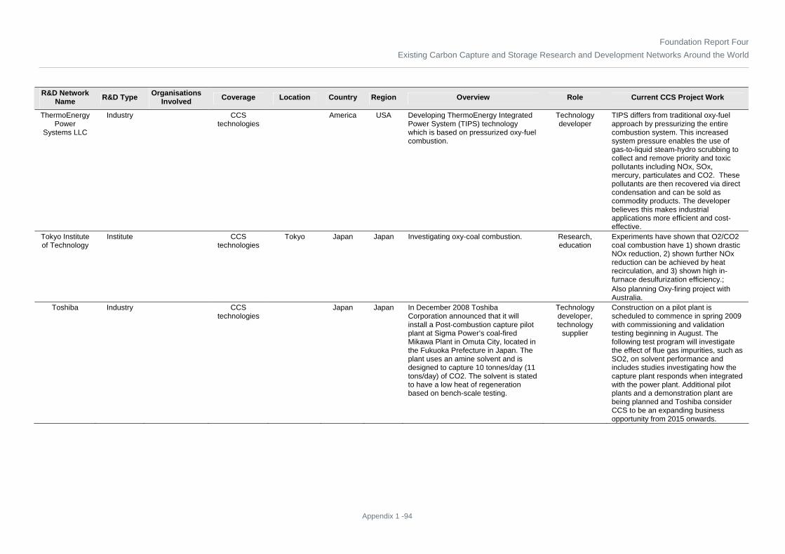
Foundation Report FourExisting Carbon Capture and Storage Research and Development Networks Around the World
Appendix 1 -94
R&D Network Name R&D Type Organisations
Involved Coverage Location Country Region Overview Role Current CCS Project Work
ThermoEnergy Power
Systems LLC
Industry CCS technologies
America USA Developing ThermoEnergy Integrated Power System (TIPS) technology which is based on pressurized oxy-fuel combustion.
Technology developer
TIPS differs from traditional oxy-fuel approach by pressurizing the entire combustion system. This increased system pressure enables the use of gas-to-liquid steam-hydro scrubbing to collect and remove priority and toxic pollutants including NOx, SOx, mercury, particulates and CO2. These pollutants are then recovered via direct condensation and can be sold as commodity products. The developer believes this makes industrial applications more efficient and cost-effective.
Tokyo Institute of Technology
Institute CCS technologies
Tokyo Japan Japan Investigating oxy-coal combustion. Research, education
Experiments have shown that O2/CO2 coal combustion have 1) shown drastic NOx reduction, 2) shown further NOx reduction can be achieved by heat recirculation, and 3) shown high in-furnace desulfurization efficiency.; Also planning Oxy-firing project with Australia.
Toshiba Industry CCS technologies
Japan Japan In December 2008 Toshiba Corporation announced that it will install a Post-combustion capture pilot plant at Sigma Power’s coal-fired Mikawa Plant in Omuta City, located in the Fukuoka Prefecture in Japan. The plant uses an amine solvent and is designed to capture 10 tonnes/day (11 tons/day) of CO2. The solvent is stated to have a low heat of regeneration based on bench-scale testing.
Technology developer, technology
supplier
Construction on a pilot plant is scheduled to commence in spring 2009 with commissioning and validation testing beginning in August. The following test program will investigate the effect of flue gas impurities, such as SO2, on solvent performance and includes studies investigating how the capture plant responds when integrated with the power plant. Additional pilot plants and a demonstration plant are being planned and Toshiba consider CCS to be an expanding business opportunity from 2015 onwards.

Foundation Report FourExisting Carbon Capture and Storage Research and Development Networks Around the World
Appendix 1 -95
R&D Network Name R&D Type Organisations
Involved Coverage Location Country Region Overview Role Current CCS Project Work
Total Industry CCS technologies
France Euro Area
Total is to convert a 30-MWt natural gas fired steam boiler operating on air to operation on oxygen to demonstrate oxy-combustion in conjunction with CO2 storage. The boiler is located at their Lacq refinery near Pau in south-west France.
Project developer,
demonstration, operator
Lacq oxy-fuel combustion demonstration: Conceptual and pre-project studies (January 2006 to February 2007); Basic engineering studies (January to October 2007); Design, manufacture, delivery and erection of ASU (May 2007 to November 2008); Boiler modifications and CO2 compressors (May 2007 to September 2008); CO2 capture and injection start up (January 2009)
TransAlta Industry Alstom, TransCanada
CCS technologies
Alberta Canada Canada Working to advance and improve understanding of CCS technology.
Project developer,
demonstration, operator
In April 2008, TransAlta announced that they would retrofit a large scale Chilled Ammonia Process project to one of its coal-fired plants west of Edmonton, Alberta to reduce CO2 emissions by 1-million tonnes (1.1-million tons/yr) year.
TransCanada Industry TransAlta, GE CCS technologies
Alberta Canada Canada Network of more than 59,000 kilometres (36,500 miles) of pipeline taps into virtually all major gas supply basins in North America. One of the continent’s largest providers of gas storage and related services with approximately 370 billion cubic feet of storage capacity. Owns, controls or is developing approximately 10,900 megawatts of power generation.
Project developer,
demonstration, operator
Working with TransAlta on Project Pioneer, Canada's first fully-integrated carbon capture and storage (CCS) plant.
TRUenergy Development
Pty Ltd
Industry Ignite Energy Resources
Economics, Public
awareness and
understanding
Melbourne Australia ANZ TRUenergy is owned by CLP Power Asia, a subsidiary of the CLP Group based in Hong Kong. CLP Power Asia invests in energy-related businesses across the Asia Pacific region, including India, Thailand, Taiwan and Australia. TRUenergy supplies gas and electricity to 1.1 million homes in Victoria, South Australia and New South Wales. They also generate electricity in both Victoria and South Australia and are looking to build a generator in NSW.
Power Plant Owner and Operator
Working with Ignite Energy Resources to demonstrate a lignite drying technology which could reduce CO2 emissions from lignite burning power plants by 40%.

Foundation Report FourExisting Carbon Capture and Storage Research and Development Networks Around the World
Appendix 1 -96
R&D Network Name R&D Type Organisations
Involved Coverage Location Country Region Overview Role Current CCS Project Work
Tsinghua University,
Beijing
Academia WRI Regulations China China Tsinghua University is partnering with WRI to develop guidelines for China’s deployment of CCS technology. Also studying low-cost CCS technologies for coal-fired plants in China.
Research, Education,
Policy Research
Tsinghua University has partnered with WRI to begin addressing how to ensure that CCS deployment in China meets environmental standards by drafting Guidelines for Safe and Effective CCS in China. The Tsinghua-WRI team will build capacity that supports regulatory development by engaging technical experts and other stakeholders in building consensus surrounding guidelines and best practices.
TU Cottbus Academia CCS technologies
Cottbus Germany Euro Area
Investigating the influence of various O2/CO2 concentrations on the burning behaviour of different coals in Oxycombustion
Research, education
Using the ALVA 20 lab test rig, different types of coals were investigated. The test focused on varying O2 and CO2 concentrations and studying the impact on combustion behaviour and combustion time.
TU Hamburg-Harburg
Academia CCS technologies
Germany Euro Area
Involved in several CCS-related research projects
Research, education
Research is being done on: Oxyfuel (ADECOS I & II and COORETEC Programme); Cement production with CCS; Post-combustion CO2 reduction (POSEIDON under COORETEC Programme)
UCG Partnership
Industry See long list of members:
http://www.ucgp.com/ucg-
partnership/current-members/
Information Sharing
Surrey England Euro Area
The Partnership speaks for the industry and provides public information on all aspects of Underground Coal Gasification (UCG) including carbon capture and storage (CCS). They provide speakers at conferences and engage with industry, governments, energy associations, academia, investors, bankers and others to promote UCG as a primary energy source
Information sharing, public
awareness
UCGP works with many organisations to promote and encourage research in UCG-CCS
Uhde Shedden (Australia) Pty
Ltd
Industry CCS technologies
Australia ANZ Provide multi-disciplinary engineering and project delivery services to the upstream oil and gas, oil refining, petrochemical, chemical and resource sectors.
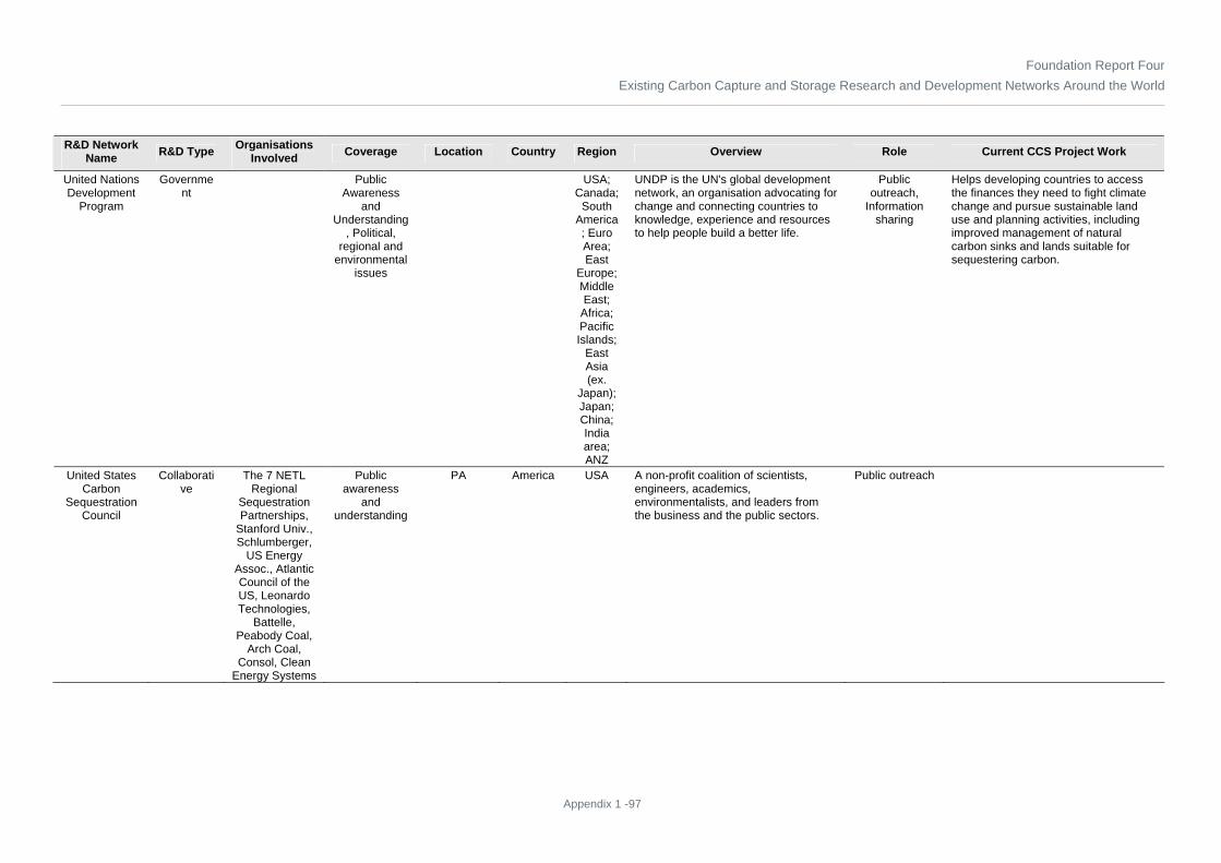
Foundation Report FourExisting Carbon Capture and Storage Research and Development Networks Around the World
Appendix 1 -97
R&D Network Name R&D Type Organisations
Involved Coverage Location Country Region Overview Role Current CCS Project Work
United Nations Development
Program
Government
Public Awareness
and Understanding
, Political, regional and
environmental issues
USA; Canada;
South America; Euro Area; East
Europe; Middle East;
Africa; Pacific Islands;
East Asia (ex.
Japan); Japan; China; India area; ANZ
UNDP is the UN's global development network, an organisation advocating for change and connecting countries to knowledge, experience and resources to help people build a better life.
Public outreach,
Information sharing
Helps developing countries to access the finances they need to fight climate change and pursue sustainable land use and planning activities, including improved management of natural carbon sinks and lands suitable for sequestering carbon.
United States Carbon
Sequestration Council
Collaborative
The 7 NETL Regional
Sequestration Partnerships,
Stanford Univ., Schlumberger,
US Energy Assoc., Atlantic Council of the US, Leonardo Technologies,
Battelle, Peabody Coal,
Arch Coal, Consol, Clean
Energy Systems
Public awareness
and understanding
PA America USA A non-profit coalition of scientists, engineers, academics, environmentalists, and leaders from the business and the public sectors.
Public outreach

Foundation Report FourExisting Carbon Capture and Storage Research and Development Networks Around the World
Appendix 1 -98
R&D Network Name R&D Type Organisations
Involved Coverage Location Country Region Overview Role Current CCS Project Work
United States Department of Energy (DOE
NETL)
Government
CCS technologies
Washington DC;
Pittsburgh, PA;
Morgantown, WV
America USA Supporting Core R&D and Demonstration and Deployment.
Funder, Research
NETL’s Carbon Sequestration Program is helping to develop technologies to capture, purify, and store carbon dioxide (CO2) in order to reduce greenhouse gas emissions without adversely influencing energy use or hindering economic growth. The activities of each of its seven regional partnerships are described in separate entries in this database. NETL is also sponsoring pre- and post-combustion capture R&D as well as advancements in H2-fired gas turbines, oxy-combustion R&D, and pilot scale chemical looping tests. DOE also administers the Clean Coal Power Initiative and FutureGen project, both of which are aimed at commercial scale demonstrations of CCS technology in coal-based power generation plants.

Foundation Report FourExisting Carbon Capture and Storage Research and Development Networks Around the World
Appendix 1 -99
R&D Network Name R&D Type Organisations
Involved Coverage Location Country Region Overview Role Current CCS Project Work
United States Energy
Association
Association 138 members but not all involved in
CCS. Membership in
the USEA includes a wide range of Energy
Companies, Trade
Associations, Manufacturers,
Engineering Companies, Professional
Societies, Government
Organizations, Professional
Service Firms, Universities,
Educational and Informational Organizations
See http://www.usea.org/Membership/memberlist.ht
m
Information sharing
Washington, DC
America USA The USEA is an association that represents the broad interests of the U.S. energy sector by increasing the understanding of energy issues, both domestically and internationally. In its role, the USEA is the U.S. Member Committee of the World Energy Council (WEC) and coordinates US participation in the WEC.
Public outreach & coordination in the US and internationally
The USEA has an active program regarding Global Climate Change that includes publishing materials, hosting events, providing grants, etc. For example, the USEA's "CO2 Capture & Storage and Clean Energy News" is distributed to a wide audience in the US and overseas. It highlights CO2 capture and storage and clean energy projects, technologies, R&D, regulatory activities, costs and funding, and state and local actions.
United States Geological
Survey (USGS)
Government
Columbia University
CCS technologies, Information
Sharing
Menlo Park, CA
America USA The USGS serves the US by providing reliable scientific information to describe and understand the Earth; minimize loss of life and property from natural disasters; manage water, biological, energy, and mineral resources; and enhance and protect our quality of life.
Research, Information
sharing
Researchers at Columbia University and the U.S. Geological Survey have developed a digital geologic database of ultramafic rocks in the conterminous United States. Mineral carbon-dioxide sequestration is a proposed greenhouse gas mitigation technology whereby carbon dioxide (CO2) is disposed of by reacting it with calcium or magnesium silicate minerals to form a solid magnesium or calcium carbonate product. The technology offers a large capacity to permanently store CO2 in an environmentally benign form via a process that takes little effort to verify or monitor after disposal.

Foundation Report FourExisting Carbon Capture and Storage Research and Development Networks Around the World
Appendix 1 -100
R&D Network Name R&D Type Organisations
Involved Coverage Location Country Region Overview Role Current CCS Project Work
Universitaet Stuttgart - IVD
Academia CCS technologies
Stuttgart Germany Euro Area
Developing oxy-combustion technology for power plants with CCS
Research, Education
Investigated: fuel characteristics (lab); flame stability and basic oxyfuel burner setup (lab and pilot); burnout and emission behaviour (lab and pilot); slagging, fouling and fly ash behaviour (lab and pilot); and operation procedures (pilot).
University College of
London
Academia CCS technologies
London UK Euro Area
Focus is on developing breakthrough technologies for large-scale reduction, removal, and sequestration of CO2
Research, Education
Based on publications, main focus is on fuel cell development. Worked on development of Carbon8 accelerated carbonation process that produces usable products such as cement.
University of Aachen
Academia CO2SINUS; DMT GmbH & Co. KG; GFZ
German Research Centre for
Geosciences
CCS technologies
Aachen Germany Euro Area
Investigating Underground Coal Gasification and CCS
Research, Education
A conceptual design of an economic and environment-friendly UCG-CCS technology will be conducted. The CO2 storage potentials of the gasified coal samples and their surround rock will be investigated. Finally, experimental results will be used for parameterisation of numerical models, which will be applied to verify the CO2 storage potentials and injectivity of the gasified coal seams.
University of Adelaide
Academia CCS technologies
Adelaide Australia ANZ Research Metal Activated Conversion of CO2
University of Alberta
Academia Encana CCS technologies
Alberta Canada Canada Researching CO2 sequestration and monitoring
Research, Education
Research activities include: geological disposal of greenhouse gases; advanced geomechanical instrumentation systems; dynamic simulation modelling in geotechnical design; and monitoring technologies for geological disposal of greenhouse gases
University of Bari, Italy
Academia CCS technologies
Italy Euro Area
Research focuses on recovery and utilisation of CO2
Research, Education
In lieu of storing captured CO2, investigating the utilization of CO2 as a source of carbon for the synthesis of products classified as fine- or bulk-chemicals. New synthetic processes using CO2 have been discovered, and some may be developed at the industrial level if suitable economic conditions were created.

Foundation Report FourExisting Carbon Capture and Storage Research and Development Networks Around the World
Appendix 1 -101
R&D Network Name R&D Type Organisations
Involved Coverage Location Country Region Overview Role Current CCS Project Work
University of Bergen
Academia The Research Council of Norway
CCS technologies,
Political Regional and Environmental
Issues
Bergen Norway Euro Area
The overall objective of the Bjerknes Centre is to understand and quantify regional climate changes in the context of the global climate system.
Research, Education
Internationally acknowledged for its research efforts in the field of paleoclimate (climate of the past), which is crucial in order to understand present and future climate changes. Due to their leading position in this and other areas, they had a central role in the IPCC’s Fourth Assessment Report (2007), including coordinating lead author, lead author and several contributing authors. Also cooperates with other research institutions concerning effects of climate change on ecosystems, health and society, which are founded in natural science.
University of California
Davis
Academia CCS technologies, Economics
CA America USA Investigating costs of CO2 capture, compression, transport, and storage.
Research, Education
Developed models for estimating the engineering requirements and costs of CCS infrastructure; Described a set of simple correlations for estimating the density and viscosity of CO2 within the range of operating temperatures and pressures that might be encountered in CCS applications; Illustrated an approach that was used to compare several recent techno-economic models for estimating CO2 pipeline sizes and costs.
University of California
Irvine
Academia CCS technologies, Economics
CA America USA Research focused on hydrogen economy
Research, Education
Dr. Samuelson’s research is directed to fuel cells and fuel cell systems for stationary applications, the hydrogen infrastructure for mobile hydrogen-fuelled combustion and fuel cell vehicles, and the development of advanced high efficiency and low emission combustion technology.
University of California Los
Angeles
Academia CCS technologies
CA America USA Developing metal organic frameworks, which is a pressure swing adsorption technology. This process is currently experimental.
Research, Education
MOFs are engineered adsorbents with very high capacities for CO2 at moderate temperatures and pressures. Current research is focused on synthesizing new MOFs and characterizing their performance.

Foundation Report FourExisting Carbon Capture and Storage Research and Development Networks Around the World
Appendix 1 -102
R&D Network Name R&D Type Organisations
Involved Coverage Location Country Region Overview Role Current CCS Project Work
University of California
Santa Cruz
Academia CCS technologies
CA America USA Developing a concept to capture CO2 from power plants that draw cooling water from the ocean.
Research, Education
The process first dissolves CO2 in water then pass the acidified water through powdered limestone to produce aqueous calcium carbonate that is discharged back to the ocean. The limestone must be replenished continuously.
University of Cambridge
Academia Leeds University;
Imperial College London; Cranfield
University; University of
Kent; University of Nottingham
CCS technologies
Cambridge UK Euro Area
Investigating oxy-fuel combustion Research, Education
Leeds University, Imperial College London, Cranfield University, the University of Kent, the University of Nottingham and the University of Cambridge are working on the oxyfuel combustion process in which coal is burned in a mix of pure oxygen and power station flue gases, creating a stream of CO2 that can be captured for storage.
University of Colorado Boulder
Academia CCS technologies
CO America USA Investigating the use of ionic liquids, ionic liquid polymers and composite materials for CO2 capture. Also, investigating zeolite membranes and liquid crystal membranes for CO2 capture
Research, Education
Studying the use of ionic liquids, ionic liquid polymers and composite structures for gas separations.
University of Dresden
Academia Vattenfall; RWE; E.ON; Alstom; BHI; Siemens; TU
HH; FH Zittau/Gorliz
CCS technologies
Dresden Germany Euro Area
Investigating technical and economical feasibility of Oxyfuel technology
Research, Education
Participating in the ADECOS German research project.
University of Illinois
Academia MGSC CCS technologies
IL America USA Involved in Geological studies Research, Education
Part of team leading the Midwest Geological Sequestration Consortium (MGSC).
University of Kentucky Centre for
Applied Energy Research
Academia EPRI; East Kentucky Power
Cooperative; Kentucky
Power; Duke Energy; E.ON US; Kentucky Department of
Energy Development
and Independence
CCS technologies
KY America USA Formed an industrial-governmental-academic consortium called the Carbon Management Research Group.
Research, Education
10 yr program to improve post-combustion CO2 capture, pilot being constructed, trying different solvents.

Foundation Report FourExisting Carbon Capture and Storage Research and Development Networks Around the World
Appendix 1 -103
R&D Network Name R&D Type Organisations
Involved Coverage Location Country Region Overview Role Current CCS Project Work
University of Liege,
Department of Power
Academia CCS technologies
Liege Belgium Euro Area
Investigating CO2 capture and storage technologies, including a novel oxy-fuel combustion based gas turbine power cycle called the MATIANT cycle
Research, Education
CO2 management: technologies of CO2 capture and storage, design and development of new concepts of near zero emission fossil fuels fired power plants and more particularly, design of a novel oxy-fuel combustion based gas turbine power cycle, called the MATIANT cycle in the literature; Advanced technologies for conversion of fossil fuels (supercritical and IGCC coal based power plants, advanced gas turbines and combined cycles, cogeneration)
University of Massachusetts
, Dept of Environmental,
Earth and Atmospheric
Sciences
Academia CCS technologies,
Political Regional and Environmental
Issues
MA America USA Investigating ocean storage of CO2 Research, Education
In laboratory scale experiments, found that admixing finely ground CaCO3 with liquid CO2 and water, an emulsion is formed of droplets of liquid CO2 coated with CaCO3 particles. Call the particle coated droplets globules. For the formation of the emulsion only a fraction of the weight of liquid carbon dioxide in the form of pulverized limestone is necessary. The globules appear to be stable, and depending on the CaCO3 particle size and droplet diameter, their mass can be lighter, equal or heavier than pure seawater. project aims to develop defect-free, contaminant-resistant, hydrothermally stable molecular sieve membrane films with minimally tortuous path for diffusion of the preferred hydrogen molecules from the shifted synthesis gas mixtures (DOE share: $793,775 USD; recipient share: $199,997 USD) ; duration: 48 months).

Foundation Report FourExisting Carbon Capture and Storage Research and Development Networks Around the World
Appendix 1 -104
R&D Network Name R&D Type Organisations
Involved Coverage Location Country Region Overview Role Current CCS Project Work
University of Melbourne
Academia CCS technologies
Melbourne Australia ANZ Membrane Development Research Performance of Novel Equipment for Solvent Absorption Systems – solvent systems, column internals, cost evaluations. Innovative Membrane Systems – glassy polyimide gas-separation membranes at elevated temperature, plasticization and effect of other gas components characterizing structure and performance of 6DFA polymer systems, optimization of membrane module design.
University of Minnesota Centre for Science,
Technology and Public
Policy
Academia Regulations MN America USA Investigating public policy Policy Research, Education
Developing comparison of CCS legislative frameworks
University of New South
Wales
Academia CCS technologies
New South Wales
Australia ANZ Membrane Development Research Innovative Membrane Systems – glassy polyimide gas-separation membranes at elevated temperature, plasticization and effect of other gas components characterizing structure and performance of 6DFA polymer systems, optimization of membrane module design.
University of Newcastle (Australia)
Academia CCS technologies
Australia ANZ Investigating oxy-combustion heat transfer and burner operation.
Research, Education
Experiments were carried out in a 1.2-MWt down-fired burner test facility complete with RFG. The heat transfer performance of a 30-MW furnace was modelled in support of the Callide A project.
University of North Dakota
EERC
Academia CCS technologies
Fargo, ND America USA Part of a technology demonstration program conducted by the EERC's Plains CO2 Reduction (PCOR) Partnership.
Research, Demonstration
Lead agency for US DOE's Plains CO2 Reduction Partnership (PCOR)

Foundation Report FourExisting Carbon Capture and Storage Research and Development Networks Around the World
Appendix 1 -105
R&D Network Name R&D Type Organisations
Involved Coverage Location Country Region Overview Role Current CCS Project Work
University of Notre Dame
Academia CCS technologies
IN America USA Developing a new ionic liquid absorbent and accompanying process that enables 90% of the post-combustion CO2 to be removed from a coal-fired power plant
Research, Education
Developing novel ionic liquid absorbents and an associated process for the removal of CO2 from coal-fired power plant flue gas. Ionic liquids are potentially more selective, have greater carrying capacity, and require less energy for regeneration
University of Nottingham -
Centre for Innovation in
CCS
Academia E.ON UK; EPSRC;
Nottingham, Newcastle,
Edinburgh and Leeds
Universities
CCS technologies
UK Euro Area
An interdisciplinary, innovative, and international leading centre for research at the interface between science and engineering and international cooperation to accelerate the technological innovation needed for the wider deployment of carbon capture and storage (CCS).
Research, Education
Announced May 2009, The University of Nottingham will share in GBP 6.9 million of research funding to study carbon capture and storage (CCS) technologies that can help cut CO2 emissions from fossil-fuel power plants. E.ON UK and the Engineering and Physical Sciences Research Council (EPSRC) will fund four university-led projects. Nottingham, Newcastle, Edinburgh and Leeds universities’ project teams will study combustion and CO2 capture and transport technologies that could help meet UK’s emission reduction goals.
University of Perugia, Italy,
Dipartimento di Ingegneria Industriale
Academia CCS technologies, Information
Sharing
Perugia Italy Euro Area
Research in carbon capture and removal started in 1997. Have published several papers on the modelling of carbon removal technologies, fuel decarbonisation and power plants integrating mitigation technologies.
Research, Education

Foundation Report FourExisting Carbon Capture and Storage Research and Development Networks Around the World
Appendix 1 -106
R&D Network Name R&D Type Organisations
Involved Coverage Location Country Region Overview Role Current CCS Project Work
University of Pittsburgh
Academia US DOE NETL CCS technologies
Pittsburgh, PA
America USA Developing novel physical solvents for CO2 capture without cooling the gas. CCS research also includes membranes and biomass
Research, Education
1) Reaction Equilibrium of Carbonation of Transition Metal Oxides and Hydroxides: a Practical Method to Screen Possible Reactions for CO2 Capture; 2) Selected fluorinated and ionic physical solvents, according to criteria established for an "ideal" solvent, are being investigated for CO2 capture from a simulated shifted gas stream rich in H2 and CO2; 3) Chemical Looping for Combustion and Hydrogen Production; 4) Novel Membranes for CO2 Removal; 5) Solvents for CO2 Capture; 6) Engineering economic analysis of biomass IGCC with carbon capture and storage. 7) Developing ionic liquids or poly (ionic liquids) to be used as sorbents or membranes which will allow a decrease in the cost of carbon dioxide capture from coal-based power generation to such extent that 90 percent of the carbon dioxide
University of Queensland
Academia CCS technologies
Brisbane Australia ANZ Studies into Layered double hydroxides (LDH)
Research
University of Regina -
International Performance Assessment Centre for Geologic
Storage of CO2 (IPAC-
CO2)
Academia Government of Saskatchewan;
Royal Dutch Shell; University
of Calgary; University of
Alberta; Dalhousie
University; and groups in Australia,
Europe, South Africa and
Brazil, with the potential of
China and India joining.
CCS technologies, Regulations
Saskatchewan
Canada Canada The IPAC-CO2 will focus on key elements of the geological storage of CO2. It will provide research that will be instrumental in helping governments develop the policies and regulations required for the large-scale deployment of CCS.
Research, Education, Information
Sharing, Public Outreach
Assessing proposed CCS projects around the world and advising on the proper management of technical issues and performance monitoring; Informing stakeholders and the public about CCS from an independent, science-based perspective; Networking internationally to share and build on the findings of other research organisations.

Foundation Report FourExisting Carbon Capture and Storage Research and Development Networks Around the World
Appendix 1 -107
R&D Network Name R&D Type Organisations
Involved Coverage Location Country Region Overview Role Current CCS Project Work
University of Regina -
International Test Centre
Academia SaskPower, EnCana, HTC
Purenergy; E.ON UK; Saudi Aramco; RITE;
AERI; RWE npower; B&W,
Natural Resources Canada;
Saskatchewan Energy &
Resources
CCS technologies
Saskatchewan
Canada Canada The ultimate goal of the research program is to develop more effective CO2 separation processes to remove CO2 from flue gases, industrial gas processing plants, and other industrial gas streams.
Research, Education
Determination of CO2 absorption capacity; Evaluations of Thermodynamic Data (related to gas separation processes); Studies of CO2 absorption kinetics in various solvents; Formulation of high performance CO2 absorption solvents; Searching for high performance absorbers and regenerators; Studies of Reactive Membranes for Gas Separation Processes; Developing design strategies for high efficiency CO2 absorption processes; Studies of corrosion and corrosion control in CO2 & Solvent environments; Studies of solvent degradation in CO2 absorption processes; Modelling and simulation of gas separation processes; Optimization and cost studies of cogeneration-based CO2 capture; Knowledge-based systems for solvent selection in CO2 separation processes; Intelligent monitoring and control of CO2 generating systems
University of Saskatchewan
Academia CCS technologies
Saskatchewan
Canada Canada Assessing the impact of geomechanical processes on geological storage of greenhouse gases.
Research, Education
Collaborating with IBM to apply new high-performance computer chips, achieving a greater understanding of how to build coal-fired electricity plants that emit less carbon dioxide. Technology will also help determine how these plants can be modified to harness carbon dioxide before it’s released, and transform it into more benign by-products or even into environmentally friendly fuels such as methanol.
University of South
Alabama
Academia CCS technologies
AL America USA Researching potential of ionic liquids Research, Education
Prepared Task-Specific Ionic Liquids that contain appended amine groups, which allow the ionic liquids to act as scavengers for CO2
University of Stuttgart
Academia CCS technologies
Stuttgart Germany Euro Area
ISSC Project. Innovative in-situ CO2 capture technology for solid fuel gasification
Research, Education
Participant in ENCAP, CASTOR, CO2SINK ISSC projects

Foundation Report FourExisting Carbon Capture and Storage Research and Development Networks Around the World
Appendix 1 -108
R&D Network Name R&D Type Organisations
Involved Coverage Location Country Region Overview Role Current CCS Project Work
University of Sydney
Academia CCS technologies
Sydney Australia ANZ Sorbent Development Research develop tailored nanoparticle adsorbents for CO2 and other greenhouse gases using advanced chemical methods. When these sorbents are used in conjunction with coal, biomass and waste fuels it is possible to increase the hydrogen production rate from around 40% to 80% by volume. have shown previously that a calcium oxide sorbent is a suitable CO2 sorbent, however the gasification reactions produce a gas mixture containing CO, CH4 and tars, as well as H2 and CO2. Additional H2 can be produced by catalytically steam reforming tars and methane and converting CO via high and low temperature water-gas-shift reactions
University of Texas at
Austin, Bureau of Economic
Geology
Academia; Governme
nt
SECARB CCS technologies,
Public Awareness
and Understanding, Information
Sharing, Political
Regional and Environmental
Issues
Austin, TX America USA The Bureau not only curates the largest volume of subsurface core and cuttings in the United States at three world-class centres located in Houston, Austin, and Midland, but also runs a major Texas well log library, with nearly 1 million well records on file.
Research, Education, Information
Sharing, Public Outreach
Conducts basic and applied research related to energy resources including oil, natural gas, and coal; mineral resources; coastal processes; Earth and environmental systems; hydrogeology; carbon sequestration; nanotechnology; energy economics; and geologic mapping. In December 2007, the Bureau received a 10-year $38M subcontract to conduct the first intensively monitored, long-term project in the US studying the feasibility of injecting a large volume of CO2 for underground storage. This project is a Phase III research program of the SECARB.
University of Texas at Austin,
Department of Petroleum and Geosystems Engineering
Academia CCS technologies
TX America USA five faculty members and five graduate students are addressing sequestration and enhanced oil recovery
Research, education

Foundation Report FourExisting Carbon Capture and Storage Research and Development Networks Around the World
Appendix 1 -109
R&D Network Name R&D Type Organisations
Involved Coverage Location Country Region Overview Role Current CCS Project Work
University of Utah Clean
Coal Program
Academia CCS technologies
Salt Lake City, UT
America USA The Utah Clean Coal Program's mission is the generation of scientific and technical breakthroughs that allow coal to be used as an energy source in a carbon-constrained world. Key research areas will target the elimination of pollutants and greenhouse gases, and safeguarding human health and the environment.
Research, Education
Coal combustion and gasification computer simulation; Lab-scale oxy-fuel combustor and new single-particle fluidized-bed reactor; Gasification; Sequestration; Combustion chemical looping
University of Western Australia
Academia CCS technologies
Perth, W.A. Australia ANZ Research
University of Wyoming - School of Energy
Resources
Academia CCS technologies
WY America USA Evaluating accelerated mineral carbonation process as a means to capture and store CO2 from flue gas.
Research, Education
Conducted experiments at coal-fired power plant in Wyoming. Used the fly ash resulting from coal combustion as the alkaline solid mineral source to capture and store flue gas CO2. Designed fluidized bed gas-solid reactor to capture CO2.
UOP LLC Industry CCS technologies
Des Plaines, IL
America USA UOP technologies support a wide variety of gas processing applications including CO2 removal and sulphur removal.
Technology developer, technology
supplier
Offers Selexol™ Acid Gas Removal process
Uppsala University
Academia CCS technologies
Uppsala Sweden Euro Area
Uppsala University plays an active role in society, promoting growth and innovation.
Research, Education
Simulation of geologic storage
URS Group Industry Political, regional and
environmental issues
Austin, TX America USA The Company provides a range of planning, engineering and architectural design, environmental, construction, program and construction management, systems integration, operations and maintenance, and management services. They also provide a wide range of specialized technical services to federal, state and local governmental agencies, as well as private clients in the chemical, manufacturing, pharmaceutical, automotive, forest products, mining, power, oil and gas, consumer products, and food and beverage industries.
Engineering, Consulting,
Environmental Permitting, Research
Using a molecular computational approach to formulate and then fabricate superior sorbent material, will combine modelling and experiments to tailor sorbents properties for optimum CO2 capture.; Awarded contract by ExxonMobil to provide detailed engineering, procurement and construction management services for a commercial demonstration plant that will use ExxonMobil's Controlled Freeze Zone™ (CFZ™) technology, which seeks to expand the use of carbon capture and storage by reducing the cost of removing carbon dioxide from highly sour gas natural gas.

Foundation Report FourExisting Carbon Capture and Storage Research and Development Networks Around the World
Appendix 1 -110
R&D Network Name R&D Type Organisations
Involved Coverage Location Country Region Overview Role Current CCS Project Work
Vattenfall Industry CCS technologies
Germany; Sweden
Euro Area
Developing commercial concepts for CCS at power plants for implementation between 2015 and 2020.
Project developer,
demonstration, operator
Test program of the 30 MWth oxy-combustion pilot as Schwarze Pumpe is in progress. Objectives are: 1) define optimum operating conditions, 2) benchmark combustion characteristics, 3) determine interaction of ASU and boiler during load change, 4) determine corrosion rates in the boiler and flue gas path, 5) determine performance of CO2 purification plant. Planning to install CCS at one of the 6x500 MW blocks of the lignite-fired Janschwalde PC power plant near Cottbus, Germany. The selected block consists of two 250 MW boilers: one boiler will be rebuilt as an oxy-coal unit and the other will be retrofitted with post-combustion technology. Both plants are expected to enter service in 2015. Vattenfall also announced plans to build a PCC demonstration plant at the 410-MW Nordjyllands plant in northern Denmark. The contract is to be awarded in 2010 and the plant will start operation in late 2013.
VTT Technical Research Centre of Finland
Institute Foster Wheeler CCS technologies, Information
Sharing
Finland Euro Area
VTT Technical Research Centre of Finland produces a great deal of energy and environmental research information that can be utilised in both public, enterprise and personal decision-making.
Research, technology
development
Working with Foster Wheeler to develop CFB technology to provide flexible air/oxy operation for a power plant with CCS. Validated one-dimensional model for the pilot-scale CFBC using Polish bituminous coal at air and oxygen combustion conditions.

Foundation Report FourExisting Carbon Capture and Storage Research and Development Networks Around the World
Appendix 1 -111
R&D Network Name R&D Type Organisations
Involved Coverage Location Country Region Overview Role Current CCS Project Work
Western Research Institute
Institute University of Wyoming
CCS technologies
Laramie, WY
America USA WRI is conducting research and developing technologies to address carbon capture and storage.
Research, technology
development
Evaluating processes for the production of oxygen for use as part of oxy-combustion of fossil fuels; Developing multi-pollutant sorbents that selectively remove air emissions, such as mercury, arsenic, selenium and carbon dioxide, from flue gases for disposition or, in the case of CO2, compression, transport and storage; Evaluating impacts of biological processes on the stored CO2; Developing tracers that can be used to monitor the movement or leakage of stored CO2
Woodside Energy Ltd
Industry CCS technologies
Perth Australia ANZ One of Australia’s top ten companies by market capitalization, and the largest publicly-traded O&G exploration and production company.
Research, technology developer
Involved in the development of “CryoCell® Technology” - an innovative process being commercialized by the Western Australian company Cool Energy that removes CO2 from NG deposits by freezing and separating the gases (the CO2 is removed as a liquid and is therefore immediately ready for geosequestration), making gas fields more economically viable.
World Coal Institute
Institute Adaro, Anglo Coal, Arch Coal,
BHP Billiton, BHP Billiton Mitsubishi Alliance,
Carbones de Zulia, Cerrejon,
Coal India, Consol Energy, Glencore, Joy
Mining Machinery, Mitsubishi
Development, Rio Tinto, Solid Energy, Store Norske, Total, Xstrata Coal
CCS technologies, Regulations,
Public Awareness
and Understanding, Information
Sharing
London UK Euro Area
A global industry association comprising the major international coal producers and stakeholders. Membership is open to companies and not-for-profit organisations with a stake in the future of coal from anywhere in the world, with member companies represented at Chief Executive level. Provides a forum for the exchange of information and the discussion of challenges relating to the coal industry.
Information sharing, public outreach, policy
research
Have established an informative website describing CCS technology with an interactive map of CCS projects worldwide.

Foundation Report FourExisting Carbon Capture and Storage Research and Development Networks Around the World
Appendix 1 -112
R&D Network Name R&D Type Organisations
Involved Coverage Location Country Region Overview Role Current CCS Project Work
World Resources
Institute
Institute Several involving
Government, Industry,
Institute and Academia
Regulations, Political,
regional and environmental issues, Public
awareness and
understanding
Washington, DC
America USA WRI’s Carbon Capture and Storage (CCS) project works with policymakers and the private sector to develop solutions to the policy, regulatory, investment, environmental and social challenges associated with CCS demonstration and deployment.
Policy Research,
Public Outreach
WorleyParsons Industry CCS technologies
PA America USA Full engineering services provider that covers the entire asset lifecycle
Engineering Hired by Tenaska, managing partner of the Taylorville Energy Centre (coal-to-SNG -to-power) project, to oversee the Front End Engineering and Design (FEED) and facility cost report of their Tanaka project. Will serve as the "owner’s engineer," coordinating preliminary project engineering and preparing reports over the approximately 12-month FEED process.
Xstrata Coal Pty Ltd
Industry FutureGen alliance, GE,
Stanwell
Queensland Australia ANZ Member of FutureGen Alliance. Working with GE and Stanwell on the Wandoan IGCC + CCS project
General funder of FG. Coal supplier for Wandoan.
See Overview comments.

Foundation Report FourExisting Carbon Capture and Storage Research and Development Networks Around the World
Appendix 1 -113
R&D Network Name R&D Type Organisations
Involved Coverage Location Country Region Overview Role Current CCS Project Work
ZEEP Australia Pty Ltd
Industry ZEEP’s initial and key
technological focus will be gasification technology through its
license agreement to commercialize
the Pratt & Whitney
Rocketdyne (PWR)
gasification technology, and
subsequently use the
technology to build Energy
Centres throughout the
world.
CCS technologies
St kilda Australia; America; Canada; Beijing
USA; Canada
Zero Emission Energy Plants, ZEEP, exists to create clean, abundant energy from our most abundant natural energy resources coal, petcoke, waste and biomass. It is ZEEP's vision to create large energy centres for the production of a variety of clean inexpensive fuels around the world.
Focus on Building and
operating gasification plants using
PWR’s compact gasifier
technology
ZEEP plans to deploy the superior Pratt & Whitney Rocketdyne (PWR) compact gasification technology, in cooperation with their strategic partners, by building and operating large-scale Energy Centres around the world.
Zero Emission Resource
Organisation (ZERO)
Environmental
Organization
Public awareness;
understanding, policy, and
environmental Issues
Oslo Norway Euro Area
Non-profit foundation that promotes carbon-free energy solutions by urging companies to choose them and cooperate to put them into use, seeking contact with policy makers to favour such solutions, and collecting and distributing information to contribute to their realization.
Policy, Research,
Public Outreach
Publishes material and links on its web-site related to CCS and organizes conferences to disseminate information to the public and industry on CCS such as the Zero Emission Conference 2009

Foundation Report FourExisting Carbon Capture and Storage Research and Development Networks Around the World
Appendix 1 -114
R&D Network Name R&D Type Organisations
Involved Coverage Location Country Region Overview Role Current CCS Project Work
Zero Emissions
Research and Technology
(ZERT)
Institute Los Alamos National
Laboratory, Lawrence Berkeley National
Laboratory, National Energy
Technology Laboratory, Lawrence Livermore National
Laboratory, Pacific
Northwest National
Laboratory, Montana State
University, West Virginia
University
CCS technologies
America USA A research collaborative focused on understanding the basic science of underground (geologic) carbon dioxide storage to mitigate greenhouse gasses from fossil fuel use and to develop technologies that can ensure the safety and reliability of that storage. The program is administered by Montana State University (Bozeman MT) where researchers test various field technologies for detecting CO2 leakage from a hypothetical storage reservoir
Research Development of sophisticated, comprehensive computer modelling suites that predict the underground behaviour of carbon dioxide; Investigation of the fundamental geochemical and hydrological issues related to underground carbon dioxide storage; Development of measurement techniques to verify storage and investigate leakage; Development of mitigation techniques and determination of best practices for reservoir management
Zhejiang University,
PRC - State Key Laboratory
of Clean Energy
Utilization
Academia CCS technologies
China China Investigating blends of solvents for chemical absorption that would increase CO2 capture efficiency and/or reduce heat requirement for regeneration
Research, education
In addition to MDEA/MEA blends, also looking at Piperazine/MDEA blends.