storm drainage design criteria - sheridan, … · 6.3.5 private drainage system connections ... the...
TRANSCRIPT
STORM DRAINAGE DESIGN CRITERIACity of Sheridan, Wyoming
August 2016

Table of Contents Chapter 1 - Introduction ........................................................................................ 1-1
Chapter 2 - Policy Requirements......................................................................... 2-1
2.1 PROJECT CLASSIFICATIONS ............................................................................................ 2-1 General Requirements for All Developments ........................................................... 2-1 2.1.1 City Contracted Projects .................................................................................................... 2-3 2.1.2 One to Two-Family Residential Lot Developments ................................................ 2-4 2.1.3 Commercial and Multi-Family Residential Property Development ................ 2-4 2.1.4 Subdivisions and Planned Unit Developments ........................................................ 2-5 2.1.5 Fully-developed Areas/Redevelopment ..................................................................... 2-7 2.1.6 Maintenance Activities ....................................................................................................... 2-7 2.1.7
2.2 EASEMENT REQUIREMENTS........................................................................................... 2-8 Easement Width Requirements ..................................................................................... 2-8 2.2.1 Easement Documentation Requirements .................................................................. 2-8 2.2.2
2.3 DEVELOPMENT WITHIN FLOODPLAINS .................................................................... 2-9
Chapter 3 - Drainage Plan Submittal Requirements .................................... 3-1
3.1 PLAN SUBMITTAL REQUIREMENTS............................................................................. 3-1 Site Stormwater Plan (SSP) .............................................................................................. 3-1 3.1.1 Comprehensive Drainage Plan (CDP) .......................................................................... 3-1 3.1.2
Chapter 4 - Rainfall .................................................................................................. 4-1
4.1 APPLICATION ........................................................................................................................ 4-1 4.2 MINOR AND MAJOR DRAINAGE SYSTEMS ................................................................. 4-1 4.3 DESIGN STORM FREQUENCY .......................................................................................... 4-1 4.4 DESIGN STORM DEPTH AND INTENSITY ................................................................... 4-2 4.5 WATER QUALITY STORM ................................................................................................. 4-3
Chapter 5 - Runoff..................................................................................................... 5-1
5.1 APPLICATION ........................................................................................................................ 5-1 5.2 DRAINAGE BASIN AREA .................................................................................................... 5-1 5.3 SELECTION OF RUNOFF CALCULATION METHODS............................................... 5-2 5.4 NRCS (SCS) HYDROGRAPH METHOD ........................................................................... 5-2
Soils Types ............................................................................................................................... 5-2 5.4.1 Time of Concentration ........................................................................................................ 5-2 5.4.2 Curve Numbers ..................................................................................................................... 5-3 5.4.3
5.5 RATIONAL METHOD ........................................................................................................... 5-4 Frequency Correction Factors ........................................................................................ 5-4 5.5.1
i | P a g e
Time of Concentration ........................................................................................................ 5-4 5.5.2 Runoff Coefficients ............................................................................................................... 5-4 5.5.3
5.6 EPA SWMM RUNOFF METHOD ....................................................................................... 5-5 5.7 MODIFIED RATIONAL METHOD .................................................................................... 5-5
Chapter 6 - Hydraulic Analysis and Design ...................................................... 6-1
6.1 APPLICATION ........................................................................................................................ 6-1 6.2 GUTTER FLOW ...................................................................................................................... 6-1
Hydraulics ............................................................................................................................... 6-1 6.2.1 Minimum Gutter Slope ....................................................................................................... 6-2 6.2.2 Inlet Spacing and Location ............................................................................................... 6-2 6.2.3
6.3 STORM DRAIN ....................................................................................................................... 6-3 Hydraulics ............................................................................................................................... 6-3 6.3.1 Materials .................................................................................................................................. 6-4 6.3.2 Access Manholes ................................................................................................................... 6-5 6.3.3 Clearance from Other Utilities ........................................................................................ 6-6 6.3.4 Private Drainage System Connections ......................................................................... 6-6 6.3.5 Outfalls ...................................................................................................................................... 6-7 6.3.6
6.4 OPEN CHANNEL CONVEYANCES ................................................................................... 6-8 General ...................................................................................................................................... 6-8 6.4.1 Clearance ................................................................................................................................. 6-8 6.4.2 Erosion Control ..................................................................................................................... 6-8 6.4.3 Freeboard Requirements .................................................................................................. 6-8 6.4.4 Low-Flow Channels ............................................................................................................. 6-9 6.4.5 Friction Factors (n) .............................................................................................................. 6-9 6.4.6 Side Slopes............................................................................................................................... 6-9 6.4.7 Maintenance Access ............................................................................................................ 6-9 6.4.8 Operation & Maintenance of Private Open Channels ............................................ 6-9 6.4.9
6.5 CULVERTS ............................................................................................................................ 6-10 Street Overtopping ............................................................................................................ 6-10 6.5.1 Headwater Depth ............................................................................................................... 6-10 6.5.2 Allowable Velocities .......................................................................................................... 6-10 6.5.3 Materials ................................................................................................................................ 6-10 6.5.4 Minimum Size ...................................................................................................................... 6-11 6.5.5 Allowance for Blockage .................................................................................................... 6-11 6.5.6 End Treatments ................................................................................................................... 6-11 6.5.7 Maintenance Access .......................................................................................................... 6-11 6.5.8
6.6 BRIDGES ................................................................................................................................ 6-11
ii | P a g e

Freeboard Requirements ................................................................................................ 6-11 6.6.1 Allowable Rise ..................................................................................................................... 6-11 6.6.2 Scour ........................................................................................................................................ 6-12 6.6.3
6.7 PUMPING STATIONS ........................................................................................................ 6-12
Chapter 7 - Runoff Control Facilities .................................................................. 7-1
7.1 APPLICATION ........................................................................................................................ 7-1 7.2 DETENTION BASINS ........................................................................................................... 7-1
Groundwater .......................................................................................................................... 7-1 7.2.1 Basin Geometry ..................................................................................................................... 7-1 7.2.2 Maximum Drain-Down Time ........................................................................................... 7-2 7.2.3 Low-Flow Channels ............................................................................................................. 7-2 7.2.4 Multi-Purpose Use ................................................................................................................ 7-2 7.2.5 Set Backs .................................................................................................................................. 7-2 7.2.6 Water Quality Treatment .................................................................................................. 7-2 7.2.7 Outlet Control Structures .................................................................................................. 7-3 7.2.8 Emergency Overflow & Spillways ................................................................................. 7-3 7.2.9
Embankments ........................................................................................................................ 7-3 7.2.10 Vegetation & Landscaping ................................................................................................ 7-4 7.2.11 Maintenance and Maintenance Access ........................................................................ 7-4 7.2.12
7.3 RETENTION/INFILTRATION BASINS .......................................................................... 7-5 Geotechnical/Hydrogeological Evaluation ................................................................ 7-5 7.3.1 Limitations .............................................................................................................................. 7-6 7.3.2 Groundwater .......................................................................................................................... 7-6 7.3.3 Basin Geometry ..................................................................................................................... 7-6 7.3.4 Maximum Drain-Down Time ........................................................................................... 7-7 7.3.5 Multi-Purpose Use ................................................................................................................ 7-7 7.3.6 Set Backs .................................................................................................................................. 7-7 7.3.7 Water Quality Treatment .................................................................................................. 7-7 7.3.8 Maintenance & Maintenance Access ............................................................................ 7-8 7.3.9
7.4 BOULEVARD SWALES ........................................................................................................ 7-8 Locations .................................................................................................................................. 7-8 7.4.1 Geotechnical/Hydrogeological Evaluation ................................................................ 7-8 7.4.2 Basin Geometry ..................................................................................................................... 7-9 7.4.3 Maximum Drain-Down Time ........................................................................................... 7-9 7.4.4 Culverts ..................................................................................................................................... 7-9 7.4.5 Landscaping and Vegetation ............................................................................................ 7-9 7.4.6 Maintenance & Maintenance Access ............................................................................ 7-9 7.4.7
iii | P a g e
Chapter 8 - Permanent Water Quality Treatment ......................................... 8-1
8.1 APPLICATION ........................................................................................................................ 8-1 8.2 WATER QUALITY VOLUME .............................................................................................. 8-2 8.3 WATER QUALITY FLOW .................................................................................................... 8-2 8.4 SELECTION OF PERMANENT WATER QUALITY BMPS ......................................... 8-3 8.5 FOREBAYS ............................................................................................................................... 8-4
Application & Limitations ................................................................................................. 8-4 8.5.1 Design ........................................................................................................................................ 8-4 8.5.2 Safety Considerations ......................................................................................................... 8-5 8.5.3 Access & Maintenance ........................................................................................................ 8-5 8.5.4
8.6 DRY BASIN .............................................................................................................................. 8-5 Minimum Drain-Down Time ............................................................................................ 8-5 8.6.1
8.7 WET BASIN ............................................................................................................................. 8-5 Application & Limitations ................................................................................................. 8-5 8.7.1 Design ........................................................................................................................................ 8-6 8.7.2 Safety Considerations ......................................................................................................... 8-7 8.7.3 Access & Maintenance Features ..................................................................................... 8-7 8.7.4
8.8 WETLANDS ............................................................................................................................. 8-7 8.9 RETENTION/INFILTRATION BASINS .......................................................................... 8-7 8.10 BIORETENTION AREAS & BIORETENTION SWALES ............................................. 8-7
Application & Limitations ................................................................................................. 8-7 8.10.1 Design ........................................................................................................................................ 8-8 8.10.2 Access & Maintenance Features ..................................................................................... 8-9 8.10.3 Maintenance Criteria ........................................................................................................ 8-10 8.10.4
8.11 SAND FILTERS .................................................................................................................... 8-10 Application & Limitations ............................................................................................... 8-10 8.11.1 Design ...................................................................................................................................... 8-10 8.11.2 Access & Maintenance Features ................................................................................... 8-12 8.11.3
8.12 SWALES ................................................................................................................................. 8-12 Application & Limitations ............................................................................................... 8-12 8.12.1 Design ...................................................................................................................................... 8-12 8.12.2 Access & Maintenance Features ................................................................................... 8-13 8.12.3
8.13 VEGETATED STRIPS ......................................................................................................... 8-13 Application & Limitations ............................................................................................... 8-13 8.13.1 Design ...................................................................................................................................... 8-13 8.13.2 Access & Maintenance Features ................................................................................... 8-14 8.13.3
8.14 OIL & WATER SEPARATORS ......................................................................................... 8-14
iv | P a g e
Application & Limitations ............................................................................................... 8-14 8.14.1 Design ...................................................................................................................................... 8-15 8.14.2 Access & Maintenance Features ................................................................................... 8-16 8.14.3
8.15 MECHANICAL TREATMENT & EMERGING TECHNOLOGY ............................... 8-16 8.16 LOW IMPACT DEVELOPMENT ..................................................................................... 8-17
Chapter 9 - Erosion and Sediment Control ...................................................... 9-1
9.1 APPLICATION ........................................................................................................................ 9-1 9.2 SWPPP AND NOI REQUIRED SUBMITTALS ............................................................... 9-1 9.3 CONSTRUCTION LESS THAN ONE-ACRE .................................................................... 9-2 9.4 BEST MANGAGEMENT PRACTICES (BMP) ................................................................ 9-2 9.5 CONSTRUCTION ADJACENT TO WATERWAYS ........................................................ 9-2
Chapter 10 - Bibliography ................................................................................... 10-1
List of Tables Table 2.1 – Requirements for Residential Lot Developments ................................................................................. 2-4 Table 2.2 – Requirements for Commercial and Multi-Family Property Developments ............................... 2-5 Table 2.3 – Requirements for Subdivisions and Planned Unit Developments ................................................. 2-6 Table 2.4 – Requirements for Fully-Developed Areas/Redevelopment ............................................................. 2-7 Table 3.1 – SSP Checklist ........................................................................................................................................................ 3-2 Table 3.2 – Comprehensive Drainage Plan (CDP) Submittals ................................................................................. 3-2 Table 4.1 – Design Storm Frequency by Zoning District ........................................................................................... 4-1 Table 4.2 – Design Storm Frequency by Street Classification ................................................................................. 4-2 Table 4.3 – Precipitation Depth – Duration (Depth In Inches) ............................................................................... 4-2 Table 4.4 – Precipitation Intensity – Duration (Intensity In Inches Per Hour) ................................................ 4-2 Table 5.1 – Acceptable Runoff Calculation Methods ................................................................................................... 5-2 Table 5.2 – Runoff Curve Numbers for Urban Areas ................................................................................................... 5-3 Table 5.3 – Frequency Correction Factors for Rational Method ............................................................................ 5-4 Table 5.4 – Runoff Coefficients ("C") for the Rational Method ............................................................................... 5-5 Table 6.1 – Allowable Use Of Streets For Minor Storm Runoff ............................................................................... 6-1 Table 6.2 – Allowable Use Of Streets For Major Storm Runoff ............................................................................... 6-1 Table 6.3 – Manning’s Coefficients (n) for Storm Drain Conduits ......................................................................... 6-4 Table 6.4 – Minimum Allowable Manhole Size .............................................................................................................. 6-5 Table 6.5 – Maximum Allowable Manhole Spacing ..................................................................................................... 6-5 Table 6.6 – Allowable Street Overtopping Depths at Culvert Crossings ........................................................... 6-10 Table 8.1 – Potential Sources of Stormwater Pollutants ........................................................................................... 8-1 Table 8.2 – NRCS Unit Peak Discharge .............................................................................................................................. 8-3 Table 8.3 – BMPs Selection for Different Pollutants ................................................................................................... 8-3
v | P a g e
List of Figures Figure 4.1 - Precipitation Depth - Durations for 5-Minutes to 3-Hours .............................................................. 4-4 Figure 4.2 - Precipitation Depth - Durations for 3-Hours to 24 Hours ................................................................ 4-5
Appendices Appendix A Additional Requirements for Commercial Site Developments
Appendix B Preliminary Drainage Report
Appendix C Final Drainage Report
Appendix D Geotechnical/Hydrogeological Report
Appendix E Operations and Maintenance Requirements
Appendix F HOA Agreement Requirements
Appendix G Template Forms
• HOA Maintenance Agreement
• BMP Inspection Form
• Report Certification Form
Appendix H Soil Infiltration Testing Requirement
Appendix I Erosion and Sediment Control BMPs
vi | P a g e

Chapter 1 - Introduction This manual shall apply to all development, redevelopment and construction activities on public and private property within the City of Sheridan. Additional guidance on the City of Sheridan development process is provided in the Developers Handbook provided on the City of Sheridan website (http://www.sheridanwy.net/wp-content/uploads/2015/07/Final-4_27_2015.pdf).
The purpose of this Manual is to provide the minimum standards to be used for the analysis and design of storm drainage systems for private development projects and City contracted projects within the City of Sheridan. This manual provides direction and guidance to allow responsible development in and around the City of Sheridan while improving water quality within the Goose Creek drainage. This manual provides guidance for the policy, design and permitting process to address stormwater runoff and treatment from proposed development and land disturbance. Design criteria and methods other than those described in these design standards shall be applied only after requesting and receiving approval from the City Public Works Department.
The design criteria presented in this manual are based on industry standard engineering practice for stormwater management, modified to suit the needs of the City of Sheridan. Depending on specific site conditions, the design of storm drainage systems may need to exceed the minimum standards presented here in order to provide adequate protection from flooding. Criteria not specifically detailed herein shall be determined in accordance with sound engineering practices, with the City’s approval.
This manual is written for use by engineers who are familiar with generally accepted hydrologic, hydraulic and hydrogeologic design practices. A detailed presentation of design methods and procedures is not included, as this information is readily available through industry-accepted publications. This manual relies, in part, on methods and procedures published in the Federal Highway Administration (FHWA) Hydraulic Engineering Circular No. 22 (HEC-22), “Urban Drainage Design Manual”, Publication No. FHWA-NHI-10-009, dated August 2013. References to specific sections of HEC-22 to be used for the design of storm drainage systems in the City of Sheridan are included throughout this document. HEC-22 is available as a PDF document from the FHWA Website (http://www.fhwa.dot.gov/engineering/hydraulics/pubs/10009/10009.pdf). In addition, this manual relies on general application, design, and installation procedures for permanent water quality BMPs as presented in the Water Environment Federation & American Society of Civil Engineers publication “Design of Urban Stormwater Controls”.
The City will conduct a limited review of Storm Drainage Plans for compliance with requirements set forth in this Manual. The Applicant is exclusively responsible for ensuring that the design, construction drawings, completed construction, and record drawings comply with acceptable engineering practices and this Manual. The City’s review of the Storm Drainage Plan is not comprehensive in nature and shall not relieve the applicant of the responsibility to use sound professional judgment. These standards are intended to assist, but not substitute for competent work by design professionals.
1-1 | P a g e

The City reserves the right to make periodic modifications to the guidelines and template forms to reflect updates to City practices. It is the responsibility of the user to determine that they are utilizing the most current version of these standards and forms.
1-2 | P a g e
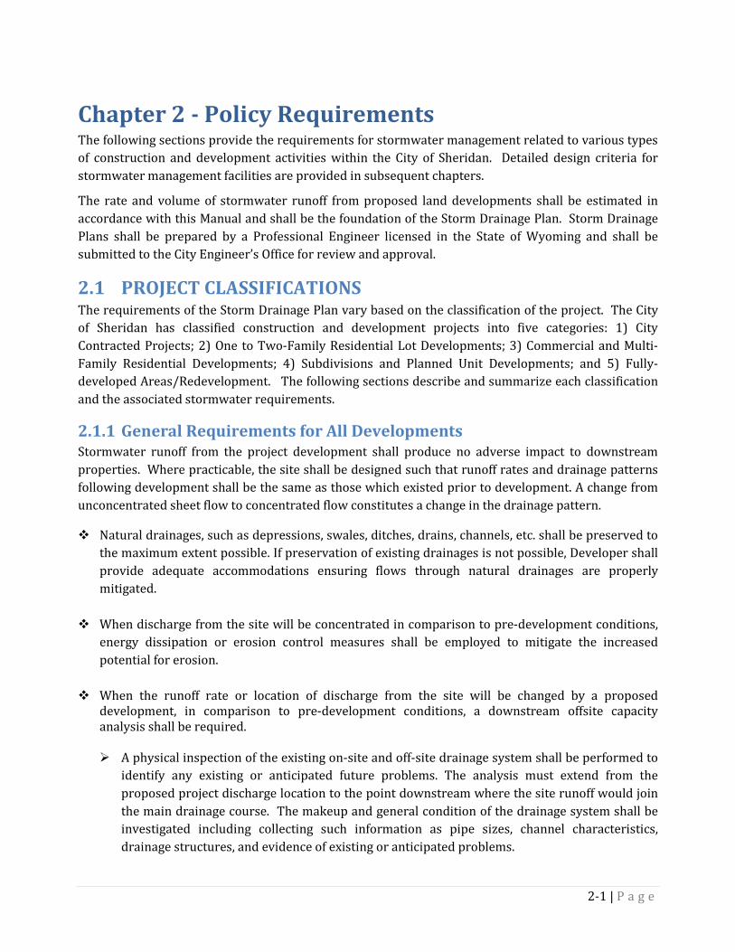
Chapter 2 - Policy Requirements The following sections provide the requirements for stormwater management related to various types of construction and development activities within the City of Sheridan. Detailed design criteria for stormwater management facilities are provided in subsequent chapters.
The rate and volume of stormwater runoff from proposed land developments shall be estimated in accordance with this Manual and shall be the foundation of the Storm Drainage Plan. Storm Drainage Plans shall be prepared by a Professional Engineer licensed in the State of Wyoming and shall be submitted to the City Engineer’s Office for review and approval.
2.1 PROJECT CLASSIFICATIONS The requirements of the Storm Drainage Plan vary based on the classification of the project. The City of Sheridan has classified construction and development projects into five categories: 1) City Contracted Projects; 2) One to Two-Family Residential Lot Developments; 3) Commercial and Multi-Family Residential Developments; 4) Subdivisions and Planned Unit Developments; and 5) Fully-developed Areas/Redevelopment. The following sections describe and summarize each classification and the associated stormwater requirements.
General Requirements for All Developments 2.1.1Stormwater runoff from the project development shall produce no adverse impact to downstream properties. Where practicable, the site shall be designed such that runoff rates and drainage patterns following development shall be the same as those which existed prior to development. A change from unconcentrated sheet flow to concentrated flow constitutes a change in the drainage pattern.
Natural drainages, such as depressions, swales, ditches, drains, channels, etc. shall be preserved to the maximum extent possible. If preservation of existing drainages is not possible, Developer shall provide adequate accommodations ensuring flows through natural drainages are properly mitigated.
When discharge from the site will be concentrated in comparison to pre-development conditions,
energy dissipation or erosion control measures shall be employed to mitigate the increased potential for erosion.
When the runoff rate or location of discharge from the site will be changed by a proposed
development, in comparison to pre-development conditions, a downstream offsite capacity analysis shall be required.
A physical inspection of the existing on-site and off-site drainage system shall be performed to
identify any existing or anticipated future problems. The analysis must extend from the proposed project discharge location to the point downstream where the site runoff would join the main drainage course. The makeup and general condition of the drainage system shall be investigated including collecting such information as pipe sizes, channel characteristics, drainage structures, and evidence of existing or anticipated problems.
2-1 | P a g e

At each location with an existing or anticipated drainage problem, develop runoff hydrographs or Rational Method peak flow rates for the major (100-yr) storm event for the total composite drainage area tributary to that location under existing conditions and the conditions that will exist following the proposed development. Determine the capacity of the existing drainage system and evaluate impacts of adding the peak runoff from the proposed project site to the peak runoff from the total composite drainage area tributary to these locations.
Solutions to Identified Drainage Problems For any potential off-site problem resulting from the development or redevelopment, the
Developer must demonstrate that the proposed project has been designed to mitigate the anticipated problem.
As an alternative, the Developer, with approval by the City, may arrange with the owners of the off-site properties to install measures which will mitigate the anticipated problem.
In some cases, anticipated public drainage system problems may already be scheduled for correction by the City. The Developer should contact the City Engineer’s Office to determine current capital improvement project schedules.
Provide information with the Drainage Report to document the capacity of the downstream drainage system and to illustrate that potential impacts have been adequately mitigated.
Where the development will result in a change in the rate of runoff or location of discharge, in comparison to pre-development conditions and no downstream drainage system exists adjacent to the property, the downstream drainage system shall be extended up to the property line and all runoff from the property shall be conveyed across the downstream properties to an approved discharge location. The Developer shall secure drainage easements from the downstream property owners and record such easements prior to drainage plan approval.
If the Developer demonstrates that easements are not reasonably obtainable as determined by
the City, then all runoff shall be conveyed to an on-site retention system. Non-stormwater discharge (illicit discharge) is prohibited from entering the storm drain system.
This includes groundwater, wash water, interior building drainage water, irrigation water, etc. There exists the potential for irrigation/drain ditches to overtop during rain events, resulting in
flooding to adjacent properties. Developers shall mitigate for this potential by requiring flood proofing of buildings, establishing appropriate building elevations, constructing overflow channels, developing appropriate site grading, or employing other measures as appropriate. In addition, there exists the potential for adjacent irrigation/drain ditches to leak, contributing to seasonally high groundwater conditions within the development. Developers shall mitigate for this potential through the construction of appropriate groundwater drainage systems. The degree of improvements required will depend on the character of the adjacent ditch and the proximity to the development.
2-2 | P a g e

Irrigation ditches shall not be used as an outfall for stormwater discharge. Exceptions, if granted, shall require approval from the ditch company and the City of Sheridan.
A Development Agreement between the City and the developer/property owner shall be required
for all developments involving public infrastructure. This includes installation of new public infrastructure as well as extension and/or replacement of exiting public infrastructure.
City Contracted Projects 2.1.2The following requirements apply to projects contracted by the City of Sheridan, including road reconstruction projects, new road construction, and other projects that impact existing drainage patterns within the City of Sheridan right of way.
City Contracted projects shall follow design criteria included in this manual. Runoff control and water quality treatment requirements will be established by the City Engineer managing the project.
Submit a Storm Drainage Memo for projects which result in only minor impacts to existing
drainage patterns. The City Engineer’s Office will determine whether the impact will be considered “minor” or “major” on a case-by-case basis.
Submit a Comprehensive Drainage Plan (CDP), in accordance with Chapter 3 of this manual, for
projects which result in major impacts to existing drainage patterns. The CDP shall identify any changes in flood hazards during the Major Storm for projects which result in major impacts to existing drainage patterns.
2-3 | P a g e

One to Two-Family Residential Lot Developments 2.1.3The requirements presented in Table 2.1 apply to residential lot developments, including single family homes, duplexes, townhomes, and condos involving two or less living units located on a single lot.
Table 2.1 – Requirements for Residential Lot Developments Drainage Design Criteria Reference
Site grading requirements shall adhere to the requirements established in/on the subdivision plat, Development Agreement, or any covenants within the subdivision. N/A
Unmitigated runoff generated from a residential site (or new improvements) shall not drain from that site to a neighboring property. N/A
If a common drainage approach is used which develops a solution for side and backyard runoff, Developer shall specify in the subdivision plat and Development Agreement the details and practices to be followed by subsequent property owners.
N/A
Hard surfaces, including gutter downspouts shall drain onto lawns or pervious areas providing a minimum length of 15-feet for runoff to disperse prior to reaching the property line, with slopes no greater than 5% for lawns and no greater than 2% for other pervious areas.
N/A
Property owners may not alter existing drainage patterns of their lot without prior approval from the City Engineer. N/A
Residential lot owners are encouraged to use LID methods on their lot. Section 8.16 The elevation of residential dwellings and other lot features must be established in recognition of the City’s policy that storm runoff flows are allowed to a depth of 18-inches in the gutter flowline of adjacent streets during the Major storm.
Section 6.2
Determine if your project requires a Stormwater Pollution Prevention Plan (SWPPP) from Wyoming DEQ; if so submit SWPPP and NOI Forms. Chapter 9
Downspouts with unfinished landscaping shall be equipped with sediment bags and/or energy dissipaters until landscaping establishes.
Stormwater features shall be preserved per the initial design and be maintained by the property owner.
Development Agreement &
Section 7.4 Submittals Reference
Submit a Site Stormwater Plan (SSP) detailing lot grading and drainage plan. Section 3.1.1
Commercial and Multi-Family Residential Property Development 2.1.4The requirements presented in Table 2.2 apply to commercial and multi-family residential development projects, including duplexes, townhomes and condo developments constructing three or more living units located on a single lot, for sites over 10,000 square feet in area or with site improvement of over 5,000 square feet of impervious surface. For sites less than 10,000 square feet in area or with site improvements of less than 5,000 square feet of impervious surface, the requirements of Table 2.1 shall apply.
Due to the potential for increased pollutant runoff, some sites may include additional regulatory and design requirements. Refer to Appendix A for the following facilities:
Fueling station, facility storing/transporting more than 1,500 gallons of petroleum products, hydraulic equipment storage, vehicle maintenance/repair, nurseries, lawn care/fertilizer facility, agricultural or animal care facility, or other similar facilities.
2-4 | P a g e
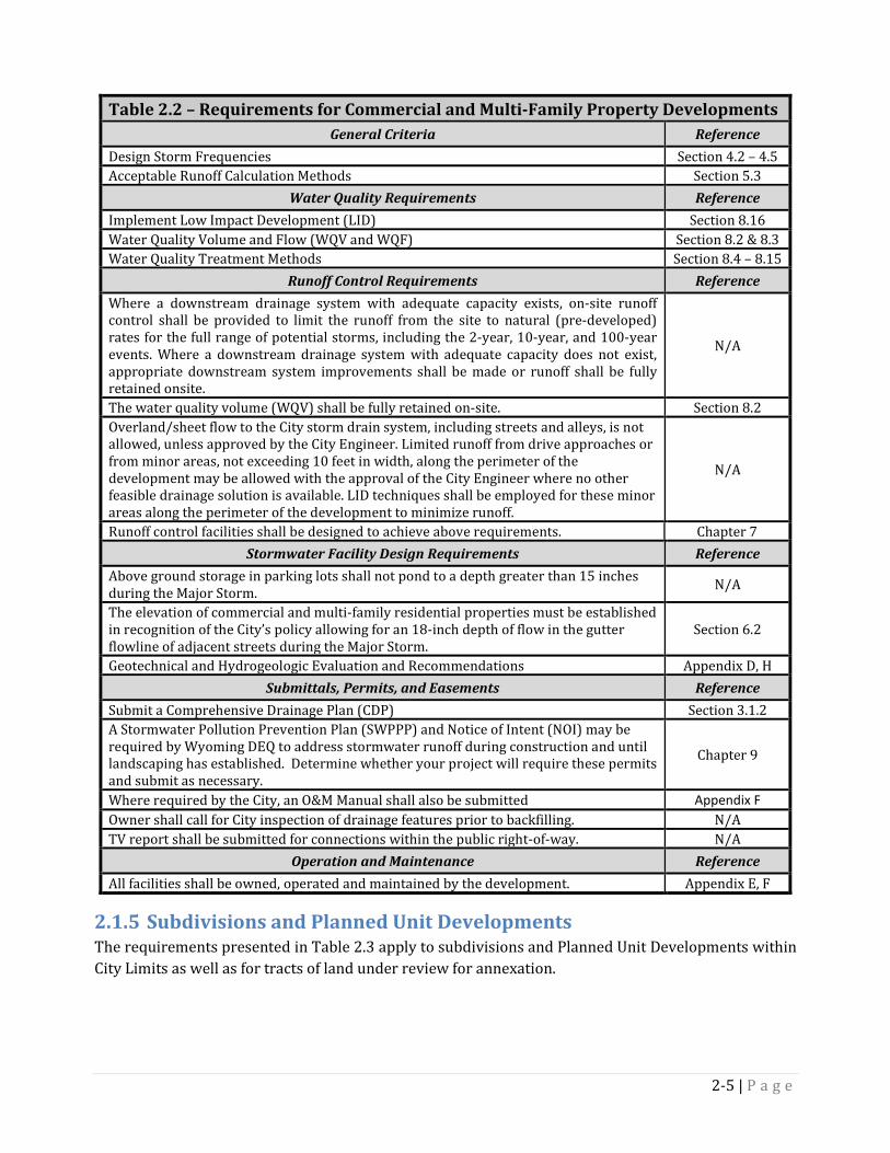
Table 2.2 – Requirements for Commercial and Multi-Family Property Developments General Criteria Reference
Design Storm Frequencies Section 4.2 – 4.5 Acceptable Runoff Calculation Methods Section 5.3
Water Quality Requirements Reference Implement Low Impact Development (LID) Section 8.16 Water Quality Volume and Flow (WQV and WQF) Section 8.2 & 8.3 Water Quality Treatment Methods Section 8.4 – 8.15
Runoff Control Requirements Reference Where a downstream drainage system with adequate capacity exists, on-site runoff control shall be provided to limit the runoff from the site to natural (pre-developed) rates for the full range of potential storms, including the 2-year, 10-year, and 100-year events. Where a downstream drainage system with adequate capacity does not exist, appropriate downstream system improvements shall be made or runoff shall be fully retained onsite.
N/A
The water quality volume (WQV) shall be fully retained on-site. Section 8.2 Overland/sheet flow to the City storm drain system, including streets and alleys, is not allowed, unless approved by the City Engineer. Limited runoff from drive approaches or from minor areas, not exceeding 10 feet in width, along the perimeter of the development may be allowed with the approval of the City Engineer where no other feasible drainage solution is available. LID techniques shall be employed for these minor areas along the perimeter of the development to minimize runoff.
N/A
Runoff control facilities shall be designed to achieve above requirements. Chapter 7 Stormwater Facility Design Requirements Reference
Above ground storage in parking lots shall not pond to a depth greater than 15 inches during the Major Storm. N/A
The elevation of commercial and multi-family residential properties must be established in recognition of the City’s policy allowing for an 18-inch depth of flow in the gutter flowline of adjacent streets during the Major Storm.
Section 6.2
Geotechnical and Hydrogeologic Evaluation and Recommendations Appendix D, H Submittals, Permits, and Easements Reference
Submit a Comprehensive Drainage Plan (CDP) Section 3.1.2 A Stormwater Pollution Prevention Plan (SWPPP) and Notice of Intent (NOI) may be required by Wyoming DEQ to address stormwater runoff during construction and until landscaping has established. Determine whether your project will require these permits and submit as necessary.
Chapter 9
Where required by the City, an O&M Manual shall also be submitted Appendix F Owner shall call for City inspection of drainage features prior to backfilling. N/A TV report shall be submitted for connections within the public right-of-way. N/A
Operation and Maintenance Reference All facilities shall be owned, operated and maintained by the development. Appendix E, F
Subdivisions and Planned Unit Developments 2.1.5The requirements presented in Table 2.3 apply to subdivisions and Planned Unit Developments within City Limits as well as for tracts of land under review for annexation.
2-5 | P a g e
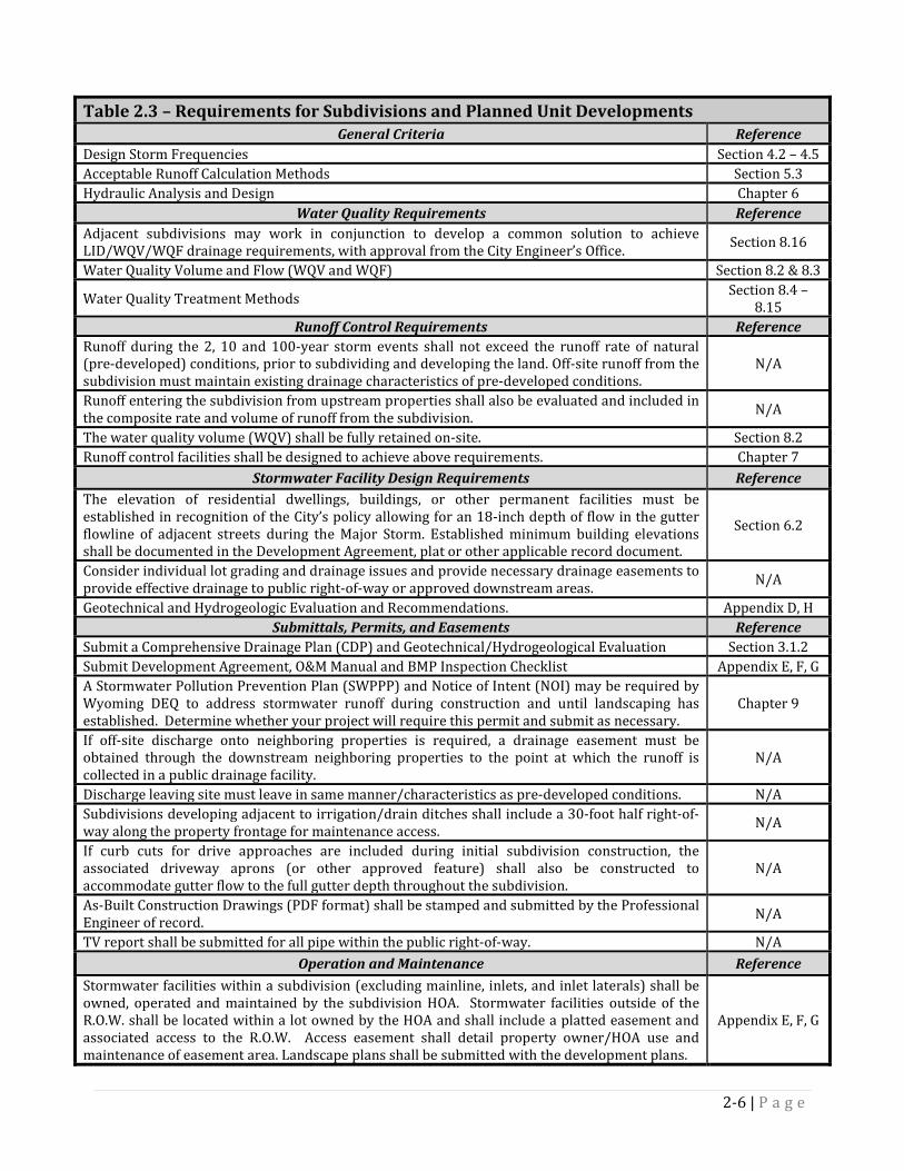
Table 2.3 – Requirements for Subdivisions and Planned Unit Developments General Criteria Reference
Design Storm Frequencies Section 4.2 – 4.5 Acceptable Runoff Calculation Methods Section 5.3 Hydraulic Analysis and Design Chapter 6
Water Quality Requirements Reference Adjacent subdivisions may work in conjunction to develop a common solution to achieve LID/WQV/WQF drainage requirements, with approval from the City Engineer’s Office. Section 8.16
Water Quality Volume and Flow (WQV and WQF) Section 8.2 & 8.3
Water Quality Treatment Methods Section 8.4 – 8.15
Runoff Control Requirements Reference Runoff during the 2, 10 and 100-year storm events shall not exceed the runoff rate of natural (pre-developed) conditions, prior to subdividing and developing the land. Off-site runoff from the subdivision must maintain existing drainage characteristics of pre-developed conditions.
N/A
Runoff entering the subdivision from upstream properties shall also be evaluated and included in the composite rate and volume of runoff from the subdivision. N/A
The water quality volume (WQV) shall be fully retained on-site. Section 8.2 Runoff control facilities shall be designed to achieve above requirements. Chapter 7
Stormwater Facility Design Requirements Reference The elevation of residential dwellings, buildings, or other permanent facilities must be established in recognition of the City’s policy allowing for an 18-inch depth of flow in the gutter flowline of adjacent streets during the Major Storm. Established minimum building elevations shall be documented in the Development Agreement, plat or other applicable record document.
Section 6.2
Consider individual lot grading and drainage issues and provide necessary drainage easements to provide effective drainage to public right-of-way or approved downstream areas. N/A
Geotechnical and Hydrogeologic Evaluation and Recommendations. Appendix D, H Submittals, Permits, and Easements Reference
Submit a Comprehensive Drainage Plan (CDP) and Geotechnical/Hydrogeological Evaluation Section 3.1.2 Submit Development Agreement, O&M Manual and BMP Inspection Checklist Appendix E, F, G A Stormwater Pollution Prevention Plan (SWPPP) and Notice of Intent (NOI) may be required by Wyoming DEQ to address stormwater runoff during construction and until landscaping has established. Determine whether your project will require this permit and submit as necessary.
Chapter 9
If off-site discharge onto neighboring properties is required, a drainage easement must be obtained through the downstream neighboring properties to the point at which the runoff is collected in a public drainage facility.
N/A
Discharge leaving site must leave in same manner/characteristics as pre-developed conditions. N/A Subdivisions developing adjacent to irrigation/drain ditches shall include a 30-foot half right-of-way along the property frontage for maintenance access. N/A
If curb cuts for drive approaches are included during initial subdivision construction, the associated driveway aprons (or other approved feature) shall also be constructed to accommodate gutter flow to the full gutter depth throughout the subdivision.
N/A
As-Built Construction Drawings (PDF format) shall be stamped and submitted by the Professional Engineer of record. N/A
TV report shall be submitted for all pipe within the public right-of-way. N/A Operation and Maintenance Reference
Stormwater facilities within a subdivision (excluding mainline, inlets, and inlet laterals) shall be owned, operated and maintained by the subdivision HOA. Stormwater facilities outside of the R.O.W. shall be located within a lot owned by the HOA and shall include a platted easement and associated access to the R.O.W. Access easement shall detail property owner/HOA use and maintenance of easement area. Landscape plans shall be submitted with the development plans.
Appendix E, F, G
2-6 | P a g e
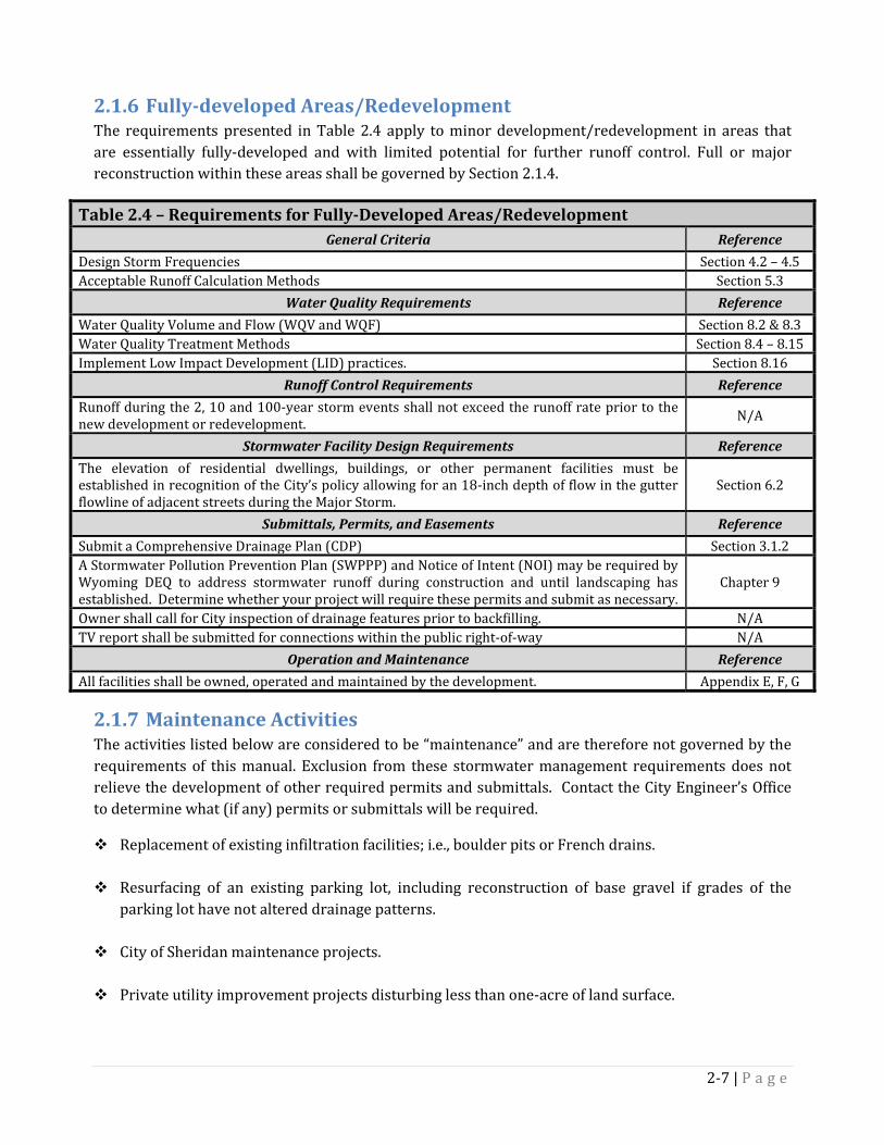
Fully-developed Areas/Redevelopment 2.1.6The requirements presented in Table 2.4 apply to minor development/redevelopment in areas that are essentially fully-developed and with limited potential for further runoff control. Full or major reconstruction within these areas shall be governed by Section 2.1.4.
Table 2.4 – Requirements for Fully-Developed Areas/Redevelopment General Criteria Reference
Design Storm Frequencies Section 4.2 – 4.5 Acceptable Runoff Calculation Methods Section 5.3
Water Quality Requirements Reference Water Quality Volume and Flow (WQV and WQF) Section 8.2 & 8.3 Water Quality Treatment Methods Section 8.4 – 8.15 Implement Low Impact Development (LID) practices. Section 8.16
Runoff Control Requirements Reference Runoff during the 2, 10 and 100-year storm events shall not exceed the runoff rate prior to the new development or redevelopment. N/A
Stormwater Facility Design Requirements Reference The elevation of residential dwellings, buildings, or other permanent facilities must be established in recognition of the City’s policy allowing for an 18-inch depth of flow in the gutter flowline of adjacent streets during the Major Storm.
Section 6.2
Submittals, Permits, and Easements Reference Submit a Comprehensive Drainage Plan (CDP) Section 3.1.2 A Stormwater Pollution Prevention Plan (SWPPP) and Notice of Intent (NOI) may be required by Wyoming DEQ to address stormwater runoff during construction and until landscaping has established. Determine whether your project will require these permits and submit as necessary.
Chapter 9
Owner shall call for City inspection of drainage features prior to backfilling. N/A TV report shall be submitted for connections within the public right-of-way N/A
Operation and Maintenance Reference All facilities shall be owned, operated and maintained by the development. Appendix E, F, G
Maintenance Activities 2.1.7The activities listed below are considered to be “maintenance” and are therefore not governed by the requirements of this manual. Exclusion from these stormwater management requirements does not relieve the development of other required permits and submittals. Contact the City Engineer’s Office to determine what (if any) permits or submittals will be required.
Replacement of existing infiltration facilities; i.e., boulder pits or French drains.
Resurfacing of an existing parking lot, including reconstruction of base gravel if grades of the parking lot have not altered drainage patterns.
City of Sheridan maintenance projects.
Private utility improvement projects disturbing less than one-acre of land surface.
2-7 | P a g e
2.2 EASEMENT REQUIREMENTS Drainage facilities that are constructed to serve predominantly public property or public right-of-way shall be publicly owned and shall be dedicated to the City.
Where possible, public conveyance systems shall be constructed within the public right-of-way. When site conditions make this infeasible, public utility easements shall be provided. Private drainage facilities shall be constructed outside of the public right-of-way, on private property, without impacting adjacent property.
When vehicle access for maintenance is required, an access easement shall be provided. The access easement conditions shall prohibit the property owner from installing any landscaping, improvements, retaining walls, etc., which would hinder access to the drainage facility or necessitate restoration of access easement area.
Easement Width Requirements 2.2.1For pipes and vaults, the required utility easement width shall be: 1) the minimum value set forth below; or 2) determined by extending a line from the bottom edge of the structure or the bottom of the excavation at the outside diameter for pipes, at a 1H : 1V slope until it intercepts the finished grade, whichever is greater.
For pipes up to five feet in diameter, the minimum easement width shall be 20 feet.
For pipes five feet in diameter and greater, the minimum utility easement width shall be the outside dimension plus 15 feet, rounded up to the nearest whole foot.
Storm drainage facilities shall be located in the center of the easement.
For open channels to be maintained by the City, the utility easement width shall include the entire width of the channel (top-of-bank to top-of-bank or width at freeboard elevation) plus a maintenance access road.
For maintenance access roads, the minimum access easement width shall be 20 feet.
Easement Documentation Requirements 2.2.2All easements shall be shown on the project plans and shall be designated “exclusively for storm drainage use”.
All utility easements shall be properly executed. Easement documents shall include a map, property legal description, and owners' names.
Easements shall be dedicated to, and approved by, the City prior to acceptance of a public drainage system and shall be filed along with the Plat with Sheridan County. Grantee shall be the "the City of Sheridan, a municipal corporation, its heirs, successors, or assignees."
Indemnification and hold-harmless agreements to hold the City harmless shall be included in recorded documents where maintenance access across private property and /or pumping of storm drainage is deemed necessary by the City.
2-8 | P a g e

Transfer of ownership for all drainage facilities appurtenant to public easements shall be given to the City with the executed real property documents that transfer property rights to the City. Grantor shall pay all title policy and recording fees necessary to transfer rights to the City.
2.3 DEVELOPMENT WITHIN FLOODPLAINS Development activity within floodplains shall be restricted in accordance with the City of Sheridan Floodplain regulations and results of the most recent Flood Insurance Study for the City of Sheridan. Stormwater runoff generated by the development during the Major Storm shall be transported to receiving channels without causing an increase in the risk of flooding in comparison to pre-development conditions.
2-9 | P a g e
Chapter 3 - Drainage Plan Submittal Requirements The intent of this chapter is to provide a framework for uniformity in Storm Drainage Plan preparation, submittal, and review to promote efficiency in the review process. In addition, properly developed drainage plans will facilitate proper operation and maintenance of drainage facilities following construction. Approval by the City does not relieve applicants from the responsibility of ensuring system performance, safety, and compliance with other local, state, and federal regulations.
3.1 PLAN SUBMITTAL REQUIREMENTS Storm Drainage Plans are divided into two categories based upon the development type; Site Stormwater Plan (SSP) and Comprehensive Drainage Plan (CDP). The applicability and requirements for each are described as follows:
Site Stormwater Plan (SSP) 3.1.1The SSP applies to all developments listed in Section 2.1.3 (and 2.1.4 where less than 10,000 SF or 5,000 SF of impervious surface) and shall be reviewed and approved prior to issuance of a building permit. The following shall be addressed in an SSP submittal:
Inform the City as to the drainage plan, the nature of the construction, project schedule, downstream conveyances, and project contact information. Plan shall include all downspout and window well locations.
Identify the drainage pattern of adjacent lots to ensure a common drainage approach within the subdivision is being achieved.
Show all easements within the lot and show/identify all site specific criteria and requirements listed within the Development Agreement.
If after review of the SSP, the City determines that more detail or information is required, the City may require a Comprehensive Drainage Plan (CDP). The SSP Checklist in Table 3.1 shall be used in assembling information necessary for review of the drainage plan:
Comprehensive Drainage Plan (CDP) 3.1.2The CDP applies to all developments listed in Section 2.1.4 through 2.1.6 and shall be reviewed and approved prior to issuance of a building and/or right-of-way permit. Table 3.2 shall be used to identify required information to be submitted for various development activities. Additional information to guide these submittals is provided in the referenced appendices.
3-1 | P a g e

Table 3.1 – SSP Checklist Submitted Contact Information Lot Owner General Contractor Engineer/Architect Project Information Address and Lot Information Project Size and Description of Land Disturbance Include total impervious area and percent impervious cover on lot Other Information Nature of Construction Limits of improvements relative to neighboring properties Direction of runoff (provide a map including adjacent lots) Methods to mitigate runoff Minimum building elevation to mitigate flood hazards Project Schedule (Start, Completion, and Final Stabilization) Water Bodies and Storm Conveyance Systems within 200 ft of the Project Delineated
Table 3.2 – Comprehensive Drainage Plan (CDP) Submittals
Required Submittal
Development Activity
Preliminary Drainage
Report
Final Drainage
Report
Geotechnical/ Hydrogeological
Report
O & M Manual HOA Development
Agreement Reference
Commercial or Multi-Family
Building Permit X X Appendix
C, D and H
Subdivision Preliminary Plat X X X Appendix
B, D and H Subdivision
Final Plat X X X X X Appendix C-H
Planned Unit Development X Appendix
B
Annexation X Appendix B
Preliminary Drainage Report 3.1.2.1The purpose of the Preliminary Drainage Report is to identify and describe site drainage impacts and illustrate preliminary solutions to the drainage system and any problems which may occur on-site and off-site as a result of the development, or any phase of the development.
The report shall provide an appropriate level of detail to address drainage issues and present the overall plan for the property. The report shall be based on the outline in Appendix B and include appropriate background information, supporting data, preliminary calculations and preliminary Storm Drainage Construction Plans.
Two (2) hard copies and one (1) digital PDF copy of the Preliminary Drainage Report and Storm Drainage Construction Plans shall be submitted to the City of Sheridan for review. The City Engineer’s Office will return one hard copy with comments and suggested revisions to the applicant.
3-2 | P a g e

Final Drainage Report 3.1.2.2The purpose of the Final Drainage Report is to provide in-depth details and calculations to address the drainage issues and present sizing and locations for all proposed improvements. The report shall be based on the outline provided in Appendix C and shall include appropriate background information and supporting data, calculations and final Storm Drainage Construction Plans.
In addition to details and calculations, the Final Drainage Report shall include a narrative describing in detail how the site and site features will function for the Minor and Major storm events.
The Final Drainage Report and Storm Drainage Construction Plans shall be submitted with the signed project certification page provided in Appendix G.
If infiltration to underlying soils will be used to manage any portion of the site runoff, refer to testing procedure outlined in Appendix H and the geotechnical/hydrogeological requirements of this manual.
The applicant shall revise the Preliminary Drainage Report to address review comments and submit two (2) hard copies and one (1) digital PDF copy of the Final Drainage Report and Storm Drainage Construction Plans for final review
Geotechnical/ Hydrogeological Report 3.1.2.3The purpose of the Geotechnical/Hydrogeological Report is to provide sufficient information such that reviewer has a clear understanding of underlying soils and groundwater characteristics and how those will interact with and be impacted by the proposed development. Potential impacts on groundwater levels, structures and facilities both within and outside the limits of development, as well as methods for mitigation, shall be addressed in the report.
The report shall be based upon the outline provided in Appendix D and shall include appropriate background information and supporting data, calculations and plan drawings.
The Geotechnical/Hydrogeological Report shall be submitted with the signed project certification page provided in Appendix G.
Operation and Maintenance (O&M) Manual 3.1.2.4The general purpose of the O&M manual is to identify the party responsible for operations and maintenance of the stormwater facility, detail maintenance schedules/activities and to ensure adherence with approved design operating conditions.
Appendix E outlines further requirements and information that shall be included in the O&M manual.
Homeowners’ Association (HOA) Agreement 3.1.2.5For subdivision development, an HOA agreement shall be submitted and approved to ensure perpetual legal validity and financial stability of the party responsible for ownership and maintenance of the stormwater facility. A template form is provided in Appendix G.
Appendix F outlines further requirements and information that shall be included in the HOA agreement.
3-3 | P a g e

Development Agreement Requirements 3.1.2.6The Development Agreement shall include language describing HOA agreements, O&M requirements, easements, property owner responsibilities and any other subdivision or building-specific stormwater mitigation requirements.
As-Built Storm Drainage Construction Plans 3.1.2.7Following construction close-out, As-Built Storm Drainage Construction Plans shall be submitted, documenting that the project was constructed in accordance with the approved final drainage plan. Any further modification from the approved final drainage plan shall be approved through an amended final drainage plan prior to construction.
The As-Built Storm Drainage Construction Plans shall be submitted along with the signed project certification page provided in Appendix G.
Template Forms 3.1.2.8Depending on the specific requirements of the development, additional agreements or forms may be required for submittal. Template forms for HOA Maintenance Agreements, BMP facility inspections, and report certifications are provided in Appendix G.
3-4 | P a g e
Chapter 4 - Rainfall 4.1 APPLICATION This chapter provides design storm frequency and precipitation data to be used in the design of stormwater management facilities for City of Sheridan contracted projects, residential lot developments, commercial property developments, subdivision developments, and Business District Development/Redevelopment and miscellaneous developments. The information provided for the Water Quality Storm is intended for use in the design of permanent water quality treatment facilities for commercial property, subdivisions, and Business District Development/Redevelopment and miscellaneous developments.
4.2 MINOR AND MAJOR DRAINAGE SYSTEMS Every urban area has two separate and distinct drainage systems, whether or not they are actually planned or designed. One is the Minor Drainage System and the other is the Major Drainage System, which are combined to form the Total Drainage System.
The Minor Drainage System is designed to transport the runoff from storm events with recurrence intervals from 2-year to 10-year with a minimum of disruption to the urban environment. Minor storm drainage can be conveyed in the curb and gutter area of the street (subject to street classification and capacity as defined herein), a roadside ditch, in the underground storm drain, open channels, or other conveyance facilities.
The Major Drainage System is designed to convey runoff from the 100-year recurrence interval storm to minimize health and life hazards, damage to structures, and interruption to traffic and services. Major storm flows can be carried in the urban street system (within acceptable depth criteria), open channels, storm sewers, and other facilities.
Drainage planning and design shall include consideration for both the Minor and Major Drainage Systems.
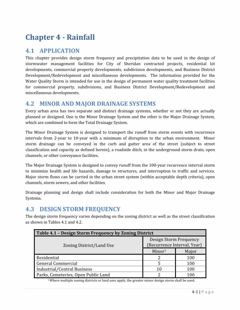
4.3 DESIGN STORM FREQUENCY The design storm frequency varies depending on the zoning district as well as the street classification as shown in Tables 4.1 and 4.2.
Table 4.1 – Design Storm Frequency by Zoning District
Zoning District/Land Use Design Storm Frequency
(Recurrence Interval, Year) Minor1 Major
Residential 2 100 General Commercial 5 100 Industrial/Central Business 10 100 Parks, Cemeteries, Open Public Land 2 100
1 Where multiple zoning districts or land uses apply, the greater minor design storm shall be used.
4-1 | P a g e
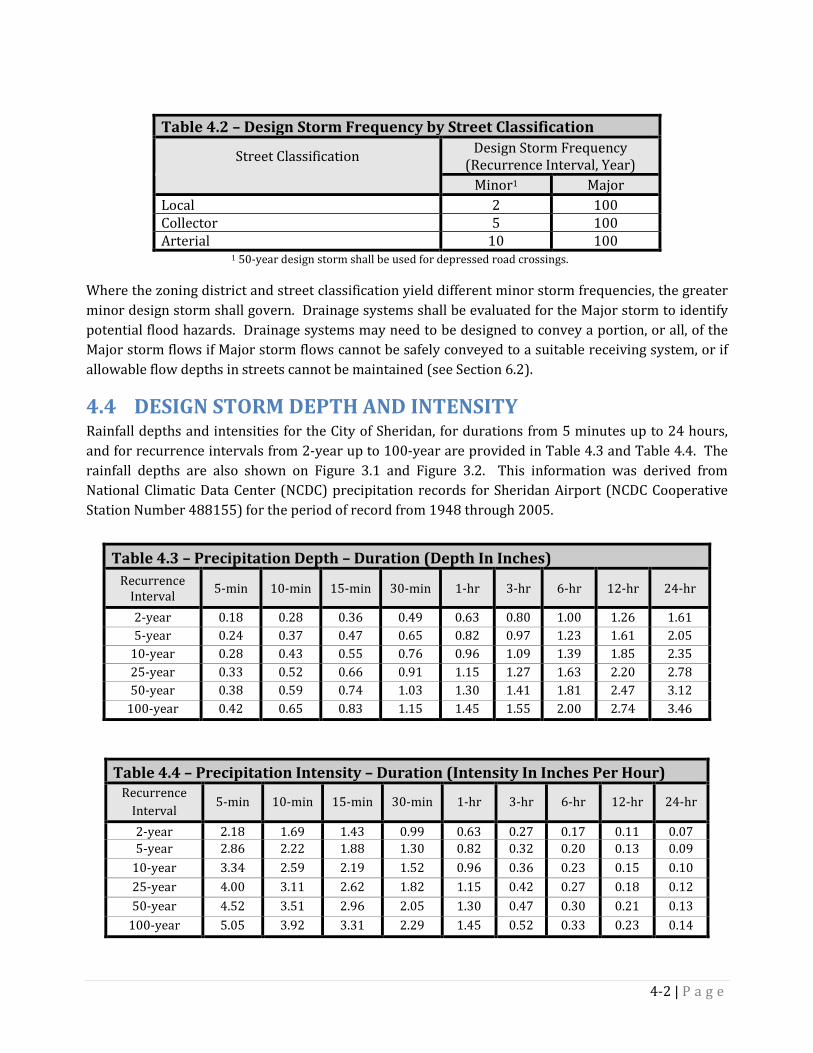
Table 4.2 – Design Storm Frequency by Street Classification
Street Classification Design Storm Frequency (Recurrence Interval, Year)
Minor1 Major Local 2 100 Collector 5 100 Arterial 10 100
1 50-year design storm shall be used for depressed road crossings.
Where the zoning district and street classification yield different minor storm frequencies, the greater minor design storm shall govern. Drainage systems shall be evaluated for the Major storm to identify potential flood hazards. Drainage systems may need to be designed to convey a portion, or all, of the Major storm flows if Major storm flows cannot be safely conveyed to a suitable receiving system, or if allowable flow depths in streets cannot be maintained (see Section 6.2).
4.4 DESIGN STORM DEPTH AND INTENSITY Rainfall depths and intensities for the City of Sheridan, for durations from 5 minutes up to 24 hours, and for recurrence intervals from 2-year up to 100-year are provided in Table 4.3 and Table 4.4. The rainfall depths are also shown on Figure 3.1 and Figure 3.2. This information was derived from National Climatic Data Center (NCDC) precipitation records for Sheridan Airport (NCDC Cooperative Station Number 488155) for the period of record from 1948 through 2005.
Table 4.3 – Precipitation Depth – Duration (Depth In Inches) Recurrence
Interval 5-min 10-min 15-min 30-min 1-hr 3-hr 6-hr 12-hr 24-hr
2-year 0.18 0.28 0.36 0.49 0.63 0.80 1.00 1.26 1.61 5-year 0.24 0.37 0.47 0.65 0.82 0.97 1.23 1.61 2.05
10-year 0.28 0.43 0.55 0.76 0.96 1.09 1.39 1.85 2.35 25-year 0.33 0.52 0.66 0.91 1.15 1.27 1.63 2.20 2.78 50-year 0.38 0.59 0.74 1.03 1.30 1.41 1.81 2.47 3.12
100-year 0.42 0.65 0.83 1.15 1.45 1.55 2.00 2.74 3.46
Table 4.4 – Precipitation Intensity – Duration (Intensity In Inches Per Hour) Recurrence
Interval 5-min 10-min 15-min 30-min 1-hr 3-hr 6-hr 12-hr 24-hr
2-year 2.18 1.69 1.43 0.99 0.63 0.27 0.17 0.11 0.07 5-year 2.86 2.22 1.88 1.30 0.82 0.32 0.20 0.13 0.09
10-year 3.34 2.59 2.19 1.52 0.96 0.36 0.23 0.15 0.10 25-year 4.00 3.11 2.62 1.82 1.15 0.42 0.27 0.18 0.12 50-year 4.52 3.51 2.96 2.05 1.30 0.47 0.30 0.21 0.13
100-year 5.05 3.92 3.31 2.29 1.45 0.52 0.33 0.23 0.14
4-2 | P a g e
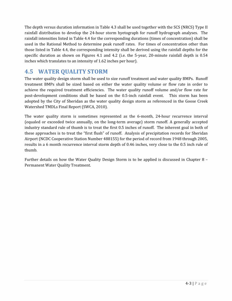
The depth versus duration information in Table 4.3 shall be used together with the SCS (NRCS) Type II rainfall distribution to develop the 24-hour storm hyetograph for runoff hydrograph analyses. The rainfall intensities listed in Table 4.4 for the corresponding durations (times of concentration) shall be used in the Rational Method to determine peak runoff rates. For times of concentration other than those listed in Table 4.4, the corresponding intensity shall be derived using the rainfall depths for the specific duration as shown on Figures 4.1 and 4.2 (i.e. the 5-year, 20-minute rainfall depth is 0.54 inches which translates to an intensity of 1.62 inches per hour).
4.5 WATER QUALITY STORM The water quality design storm shall be used to size runoff treatment and water quality BMPs. Runoff treatment BMPs shall be sized based on either the water quality volume or flow rate in order to achieve the required treatment efficiencies. The water quality runoff volume and/or flow rate for post-development conditions shall be based on the 0.5-inch rainfall event. This storm has been adopted by the City of Sheridan as the water quality design storm as referenced in the Goose Creek Watershed TMDLs Final Report (SWCA, 2010).
The water quality storm is sometimes represented as the 6-month, 24-hour recurrence interval (equaled or exceeded twice annually, on the long-term average) storm runoff. A generally accepted industry standard rule of thumb is to treat the first 0.5 inches of runoff. The inherent goal in both of these approaches is to treat the “first flush” of runoff. Analysis of precipitation records for Sheridan Airport (NCDC Cooperative Station Number 488155) for the period of record from 1948 through 2005, results in a 6 month recurrence interval storm depth of 0.46 inches, very close to the 0.5 inch rule of thumb.
Further details on how the Water Quality Design Storm is to be applied is discussed in Chapter 8 – Permanent Water Quality Treatment.
4-3 | P a g e

Figure 4.1 - Precipitation Depth - Durations for 5-Minutes to 3-Hours
0.00
0.10
0.20
0.30
0.40
0.50
0.60
0.70
0.80
0.90
1.00
1.10
1.20
1.30
1.40
1.50
1.60
0 50 100 150 200
Duration (min.)
Prec
ipita
tion
Dep
th (i
n.)
2-Year
5-Year
100-Year
50-Year
25-Year
10-Year
4-4 | P a g e

Figure 4.2 - Precipitation Depth - Durations for 3-Hours to 24 Hours
0.50
0.70
0.90
1.10
1.30
1.50
1.70
1.90
2.10
2.30
2.50
2.70
2.90
3.10
3.30
3.50
2 4 6 8 10 12 14 16 18 20 22 24 26
Duration (hrs.)
Prec
ipita
tion
Dep
th (i
n.)
2-Year
5-Year
100-Year
50-Year
25-Year
10-Year
4-5 | P a g e
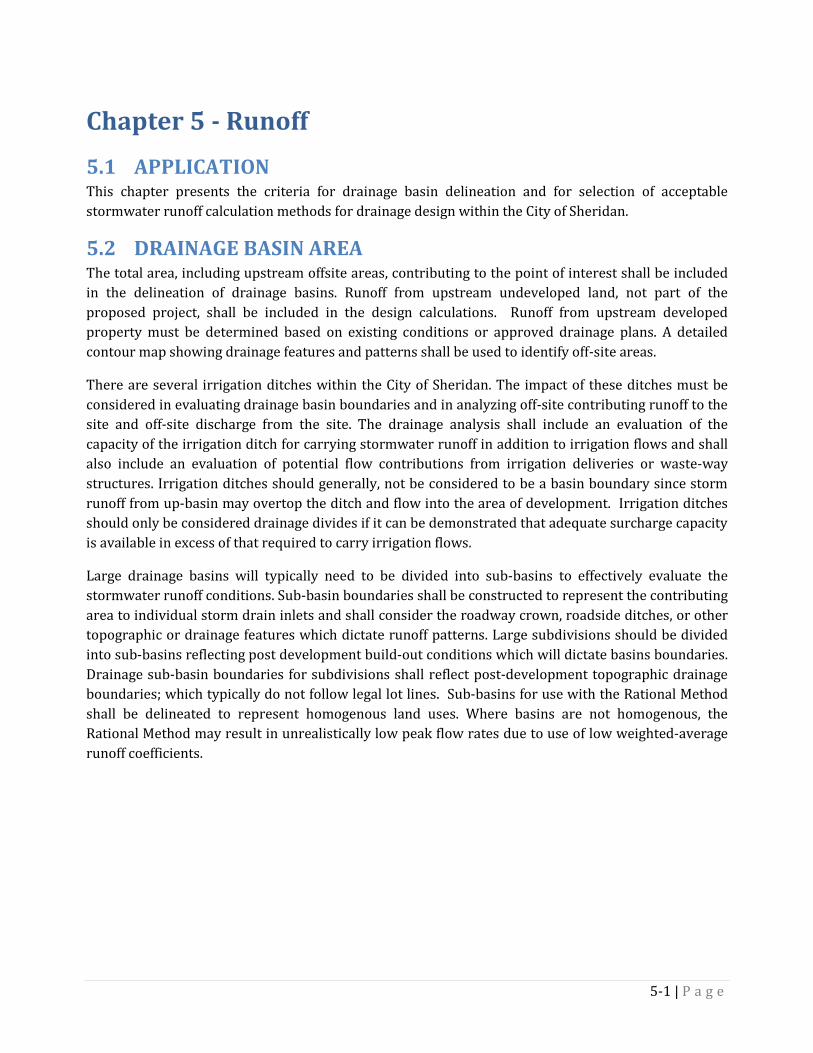
Chapter 5 - Runoff 5.1 APPLICATION This chapter presents the criteria for drainage basin delineation and for selection of acceptable stormwater runoff calculation methods for drainage design within the City of Sheridan.
5.2 DRAINAGE BASIN AREA The total area, including upstream offsite areas, contributing to the point of interest shall be included in the delineation of drainage basins. Runoff from upstream undeveloped land, not part of the proposed project, shall be included in the design calculations. Runoff from upstream developed property must be determined based on existing conditions or approved drainage plans. A detailed contour map showing drainage features and patterns shall be used to identify off-site areas.
There are several irrigation ditches within the City of Sheridan. The impact of these ditches must be considered in evaluating drainage basin boundaries and in analyzing off-site contributing runoff to the site and off-site discharge from the site. The drainage analysis shall include an evaluation of the capacity of the irrigation ditch for carrying stormwater runoff in addition to irrigation flows and shall also include an evaluation of potential flow contributions from irrigation deliveries or waste-way structures. Irrigation ditches should generally, not be considered to be a basin boundary since storm runoff from up-basin may overtop the ditch and flow into the area of development. Irrigation ditches should only be considered drainage divides if it can be demonstrated that adequate surcharge capacity is available in excess of that required to carry irrigation flows.
Large drainage basins will typically need to be divided into sub-basins to effectively evaluate the stormwater runoff conditions. Sub-basin boundaries shall be constructed to represent the contributing area to individual storm drain inlets and shall consider the roadway crown, roadside ditches, or other topographic or drainage features which dictate runoff patterns. Large subdivisions should be divided into sub-basins reflecting post development build-out conditions which will dictate basins boundaries. Drainage sub-basin boundaries for subdivisions shall reflect post-development topographic drainage boundaries; which typically do not follow legal lot lines. Sub-basins for use with the Rational Method shall be delineated to represent homogenous land uses. Where basins are not homogenous, the Rational Method may result in unrealistically low peak flow rates due to use of low weighted-average runoff coefficients.
5-1 | P a g e

5.3 SELECTION OF RUNOFF CALCULATION METHODS Acceptable hydrologic methods for determining storm drainage runoff are presented in Table 5.1.
Table 5.1 – Acceptable Runoff Calculation Methods Runoff
Calculation Method
Applications Limitations/Notes
Rational Method
- Used for determining peak runoff rates for sizing conveyance systems
- Should not be used when routing of runoff hydrographs is required
- Should only be used for developments and basins of 5 acres or less
- Should only be used for basins with homogeneous land uses
Modified Rational Method
- A simplified method used to approximate storage requirements for small drainages
- Should only be used for developments and basins of 5 acres or less
- Should only be used for basins with homogeneous land uses
NRCS (SCS)
Method
- Used for determining peak runoff rates and runoff hydrographs for large drainage basins
- Used for determining storage requirements for detention or retention facilities
- Should be used for developments and basins larger than 5 acres
EPA SWMM
- Used for complex drainage systems requiring modeling of a network of system components
- Can be used for the full range of development types. Consult with City Engineer for approval of the particular modeling software to employ the EPA SWMM method
5.4 NRCS (SCS) HYDROGRAPH METHOD The SCS Hydrograph Method shall be employed using the procedures detailed in Section 3.2.4 of the HEC-22 Manual (http://www.fhwa.dot.gov/engineering/hydraulics/pubs/10009/10009.pdf). To the extent possible, the resulting peak flows shall be verified against observed runoff during historic rainfall events in Sheridan to ensure reasonableness.
Soils Types 5.4.1Use site-specific soils information for the project site when available, or the Natural Resources Conservation Service (NRCS) Soil Survey of Sheridan County to identify the soils and corresponding hydrologic soil groups for each drainage basin
Time of Concentration 5.4.2The time of concentration shall be calculated using the procedures detailed in TR-55 (http://www.nrcs.gov/ftpref/wntsc/H&H/other/TR55documentation.pdf). Time of concentration (Tc) should range from five minute to 20 minutes for most basins. The final subdivision build-out shall be considered in determining the appropriate Tc flow path. Sheet flow lengths shall be limited to no more than 150 feet and, unless approved by the City Engineer’s Office, flow paths from backyards shall not be considered in the determination of Tc. Multiple flow path scenarios shall be evaluated in selecting the flow path which results in the shortest time of concentration, which will govern determination of the peak flow.
5-2 | P a g e
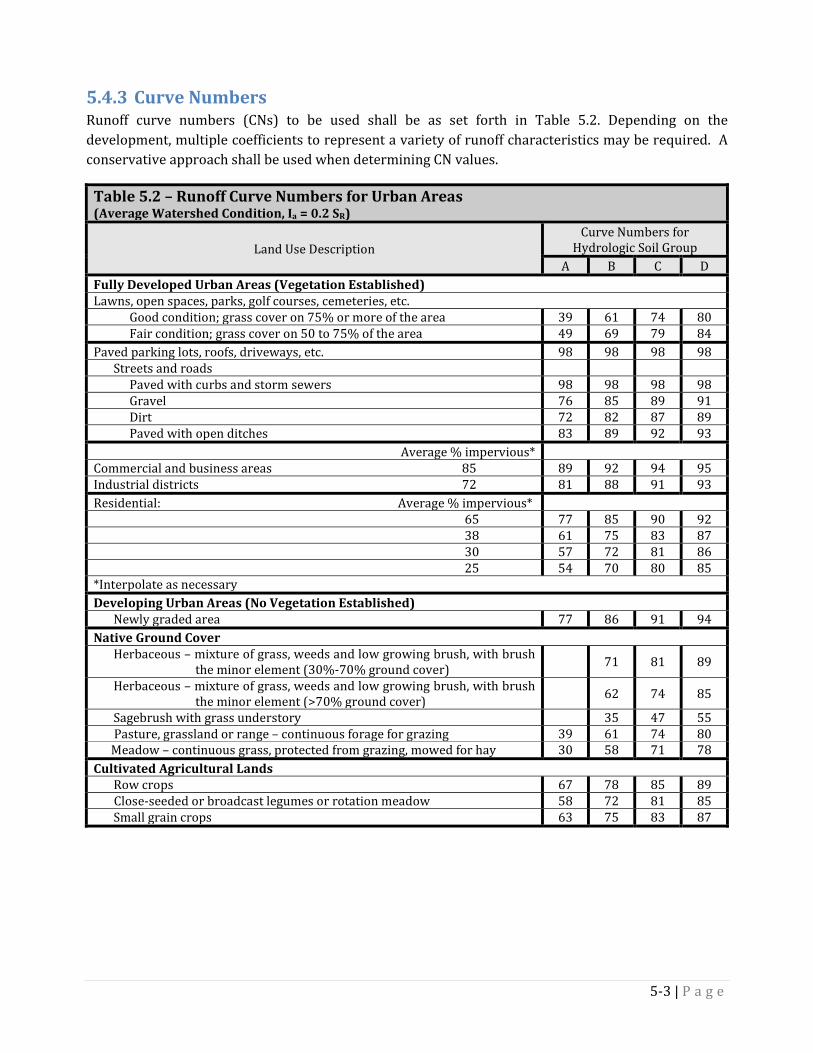
Curve Numbers 5.4.3Runoff curve numbers (CNs) to be used shall be as set forth in Table 5.2. Depending on the development, multiple coefficients to represent a variety of runoff characteristics may be required. A conservative approach shall be used when determining CN values.
Table 5.2 – Runoff Curve Numbers for Urban Areas (Average Watershed Condition, Ia = 0.2 SR)
Land Use Description Curve Numbers for
Hydrologic Soil Group A B C D
Fully Developed Urban Areas (Vegetation Established) Lawns, open spaces, parks, golf courses, cemeteries, etc. Good condition; grass cover on 75% or more of the area 39 61 74 80 Fair condition; grass cover on 50 to 75% of the area 49 69 79 84 Paved parking lots, roofs, driveways, etc. 98 98 98 98 Streets and roads Paved with curbs and storm sewers 98 98 98 98 Gravel 76 85 89 91 Dirt 72 82 87 89 Paved with open ditches 83 89 92 93
Average % impervious* Commercial and business areas 85 89 92 94 95 Industrial districts 72 81 88 91 93 Residential: Average % impervious*
65 77 85 90 92 38 61 75 83 87 30 57 72 81 86 25 54 70 80 85
*Interpolate as necessary Developing Urban Areas (No Vegetation Established) Newly graded area 77 86 91 94 Native Ground Cover Herbaceous – mixture of grass, weeds and low growing brush, with brush
the minor element (30%-70% ground cover) 71 81 89
Herbaceous – mixture of grass, weeds and low growing brush, with brush the minor element (>70% ground cover)
62 74 85
Sagebrush with grass understory 35 47 55 Pasture, grassland or range – continuous forage for grazing 39 61 74 80 Meadow – continuous grass, protected from grazing, mowed for hay 30 58 71 78 Cultivated Agricultural Lands Row crops 67 78 85 89 Close-seeded or broadcast legumes or rotation meadow 58 72 81 85 Small grain crops 63 75 83 87
5-3 | P a g e

5.5 RATIONAL METHOD One of the most widely used equations for the calculation of peak runoff from small basins is the Rational formula, given as follows:
Q = CfCIA
Where: Q = Flow in cfs, Cf = correction factor for infrequent storms,
C = a dimensionless runoff coefficient, I = rainfall intensity in inches per hour, and A = drainage area in acres
The Rational Method shall be applied using the procedures detailed in Section 3.2.2 of the HEC-22 Manual (http://www.fhwa.dot.gov/engineering/hydraulics/pubs/10009/10009.pdf). To the extent possible, the results shall be verified against observed runoff during historic rainfall events in Sheridan to ensure reasonableness.
Frequency Correction Factors 5.5.1Table 5.3 lists the correction factor to be used for infrequent storm events.
Table 5.3 – Frequency Correction Factors for Rational Method Recurrence Interval (years) Adjustment Factor Cf
2 and 10-year 1.00 25-Year 1.10 50-Year 1.20
100-Year 1.25 NOTE: C*Cf should not exceed 1
Time of Concentration 5.5.2The time of concentration shall be calculated using the procedures detailed in Section 3.2.2.3 of the HEC-22 Manual (http://www.fhwa.dot.gov/enginee ring/hydraulics/pubs/10009/10009.pdf). Time of concentration (Tc) should range from five minute to 20 minutes for most basins. The final subdivision or site build-out shall be considered in determining the appropriate Tc flow path. Sheet flow lengths shall be limited to no more than 150’ and, unless approved by the City Engineer’s Office, flow paths from backyards shall not be considered in the determination of Tc. Multiple flow path scenarios shall be evaluated in selecting the flow path which results in the shortest time of concentration, which will govern determination of the peak flow.
Runoff Coefficients 5.5.3Runoff Coefficients to be used shall be as set forth in Table 5.4. Depending on the development, multiple coefficients to represent a variety of runoff characteristics may be required. A conservative approach shall be used when determining coefficient values.
5-4 | P a g e
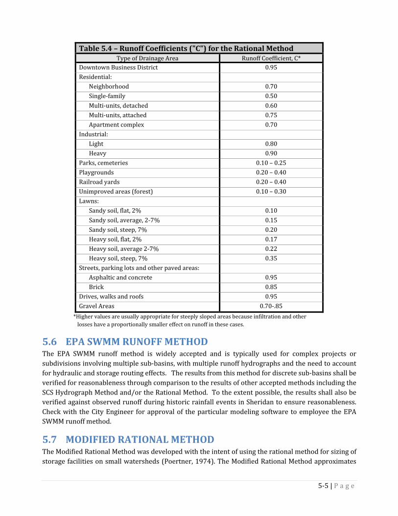
Table 5.4 – Runoff Coefficients ("C") for the Rational Method Type of Drainage Area Runoff Coefficient, C*
Downtown Business District 0.95 Residential: Neighborhood 0.70 Single-family 0.50 Multi-units, detached 0.60 Multi-units, attached 0.75 Apartment complex 0.70 Industrial: Light 0.80 Heavy 0.90 Parks, cemeteries 0.10 – 0.25 Playgrounds 0.20 – 0.40 Railroad yards 0.20 – 0.40 Unimproved areas (forest) 0.10 – 0.30 Lawns: Sandy soil, flat, 2% 0.10 Sandy soil, average, 2-7% 0.15 Sandy soil, steep, 7% 0.20 Heavy soil, flat, 2% 0.17 Heavy soil, average 2-7% 0.22 Heavy soil, steep, 7% 0.35 Streets, parking lots and other paved areas: Asphaltic and concrete 0.95 Brick 0.85 Drives, walks and roofs 0.95 Gravel Areas 0.70-.85
*Higher values are usually appropriate for steeply sloped areas because infiltration and other losses have a proportionally smaller effect on runoff in these cases.
5.6 EPA SWMM RUNOFF METHOD The EPA SWMM runoff method is widely accepted and is typically used for complex projects or subdivisions involving multiple sub-basins, with multiple runoff hydrographs and the need to account for hydraulic and storage routing effects. The results from this method for discrete sub-basins shall be verified for reasonableness through comparison to the results of other accepted methods including the SCS Hydrograph Method and/or the Rational Method. To the extent possible, the results shall also be verified against observed runoff during historic rainfall events in Sheridan to ensure reasonableness. Check with the City Engineer for approval of the particular modeling software to employee the EPA SWMM runoff method.
5.7 MODIFIED RATIONAL METHOD The Modified Rational Method was developed with the intent of using the rational method for sizing of storage facilities on small watersheds (Poertner, 1974). The Modified Rational Method approximates
5-5 | P a g e

the volume of runoff for various storm durations, with peak flows based on the time of concentration for each respective duration, and a triangular approximation of the runoff hydrograph for each. The difference between the volume of runoff into the facility and the outflow from the facility, computed for the various storm durations is used to establish the maximum required detention storage.
This simplified approach is more valid for small basins such as rooftop drainage, parking lots, or other small components of development, with contributing areas less than 5 acres.
5-6 | P a g e
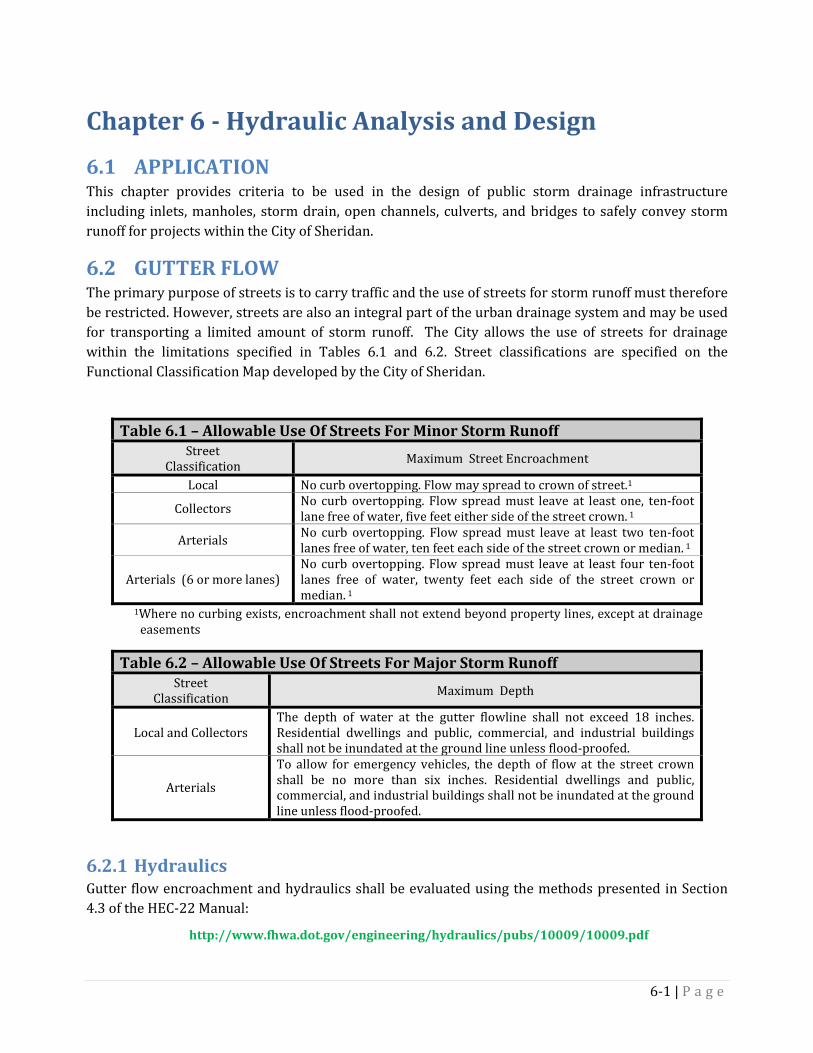
Chapter 6 - Hydraulic Analysis and Design 6.1 APPLICATION This chapter provides criteria to be used in the design of public storm drainage infrastructure including inlets, manholes, storm drain, open channels, culverts, and bridges to safely convey storm runoff for projects within the City of Sheridan.
6.2 GUTTER FLOW The primary purpose of streets is to carry traffic and the use of streets for storm runoff must therefore be restricted. However, streets are also an integral part of the urban drainage system and may be used for transporting a limited amount of storm runoff. The City allows the use of streets for drainage within the limitations specified in Tables 6.1 and 6.2. Street classifications are specified on the Functional Classification Map developed by the City of Sheridan.
Table 6.1 – Allowable Use Of Streets For Minor Storm Runoff Street
Classification Maximum Street Encroachment
Local No curb overtopping. Flow may spread to crown of street.1
Collectors No curb overtopping. Flow spread must leave at least one, ten-foot lane free of water, five feet either side of the street crown. 1
Arterials No curb overtopping. Flow spread must leave at least two ten-foot lanes free of water, ten feet each side of the street crown or median. 1
Arterials (6 or more lanes) No curb overtopping. Flow spread must leave at least four ten-foot lanes free of water, twenty feet each side of the street crown or median. 1
1Where no curbing exists, encroachment shall not extend beyond property lines, except at drainage easements
Table 6.2 – Allowable Use Of Streets For Major Storm Runoff Street
Classification Maximum Depth
Local and Collectors The depth of water at the gutter flowline shall not exceed 18 inches. Residential dwellings and public, commercial, and industrial buildings shall not be inundated at the ground line unless flood-proofed.
Arterials
To allow for emergency vehicles, the depth of flow at the street crown shall be no more than six inches. Residential dwellings and public, commercial, and industrial buildings shall not be inundated at the ground line unless flood-proofed.
Hydraulics 6.2.1Gutter flow encroachment and hydraulics shall be evaluated using the methods presented in Section 4.3 of the HEC-22 Manual:
http://www.fhwa.dot.gov/engineering/hydraulics/pubs/10009/10009.pdf
6-1 | P a g e
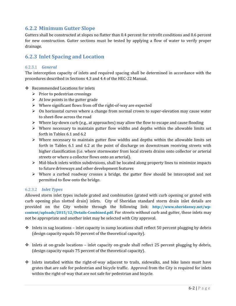
Minimum Gutter Slope 6.2.2Gutters shall be constructed at slopes no flatter than 0.4 percent for retrofit conditions and 0.6 percent for new construction. Gutter sections must be tested by applying a flow of water to verify proper drainage.
Inlet Spacing and Location 6.2.3
General 6.2.3.1The interception capacity of inlets and required spacing shall be determined in accordance with the procedures described in Sections 4.3 and 4.4 of the HEC-22 Manual.
Recommended Locations for inlets Prior to pedestrian crossings At low points in the gutter grade Where significant flows from off the right-of-way are expected On horizontal curves where a change from normal crown to super-elevation may cause water
to sheet-flow across the road Where lay-down curb (e.g., at approaches) may allow the flow to escape and cause flooding Where necessary to maintain gutter flow widths and depths within the allowable limits set
forth in Tables 6.1 and 6.2 Where necessary to maintain gutter flow widths and depths within the allowable limits set
forth in Tables 6.1 and 6.2 at the point of discharge on downstream receiving streets with higher classification (i.e. where stormwater from local streets drains onto collector or arterial streets or where a collector flows onto an arterial).
Mid-block inlets within subdivisions, shall be located along property lines to minimize impacts to future driveways and other development features
Where a curbed roadway crosses a bridge, the gutter flow should be intercepted and not permitted to flow onto the bridge.
Inlet Types 6.2.3.2Allowed storm inlet types include grated and combination (grated with curb opening or grated with curb opening plus slotted drain) inlets. City of Sheridan standard storm drain inlet details are provided on the City website through the following link: http://www.sheridanwy.net/wp-content/uploads/2015/12/Details-Combined.pdf. For streets without curb and gutter, these inlets may not be appropriate and another inlet may be selected with City approval.
Inlets in sag locations – inlet capacity in sump locations shall reflect 50 percent plugging by debris (design capacity equals 50 percent of the theoretical capacity).
Inlets at on-grade locations – inlet capacity on-grade shall reflect 25 percent plugging by debris, (design capacity equals 75 percent of the theoretical capacity).
Inlets installed within the right-of-way adjacent to trails, sidewalks, and bike lanes must have grates that are safe for pedestrian and bicycle traffic. Approval from the City is required for inlets within the right-of-way that are not safe for pedestrian and bicycle.
6-2 | P a g e
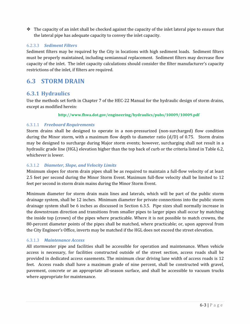
The capacity of an inlet shall be checked against the capacity of the inlet lateral pipe to ensure that the lateral pipe has adequate capacity to convey the inlet capacity.
Sediment Filters 6.2.3.3Sediment filters may be required by the City in locations with high sediment loads. Sediment filters must be properly maintained, including semiannual replacement. Sediment filters may decrease flow capacity of the inlet. The inlet capacity calculations should consider the filter manufacturer’s capacity restrictions of the inlet, if filters are required.
6.3 STORM DRAIN
Hydraulics 6.3.1Use the methods set forth in Chapter 7 of the HEC-22 Manual for the hydraulic design of storm drains, except as modified herein:
http://www.fhwa.dot.gov/engineering/hydraulics/pubs/10009/10009.pdf
Freeboard Requirements 6.3.1.1Storm drains shall be designed to operate in a non-pressurized (non-surcharged) flow condition during the Minor storm, with a maximum flow depth to diameter ratio (d/D) of 0.75. Storm drains may be designed to surcharge during Major storm events; however, surcharging shall not result in a hydraulic grade line (HGL) elevation higher than the top back of curb or the criteria listed in Table 6.2, whichever is lower.
Diameter, Slope, and Velocity Limits 6.3.1.2Minimum slopes for storm drain pipes shall be as required to maintain a full-flow velocity of at least 2.5 feet per second during the Minor Storm Event. Maximum full-flow velocity shall be limited to 12 feet per second in storm drain mains during the Minor Storm Event.
Minimum diameter for storm drain main lines and laterals, which will be part of the public storm drainage system, shall be 12 inches. Minimum diameter for private connections into the public storm drainage system shall be 6 inches as discussed in Section 6.3.5. Pipe sizes shall normally increase in the downstream direction and transitions from smaller pipes to larger pipes shall occur by matching the inside top (crown) of the pipes where practicable. Where it is not possible to match crowns, the 80-percent diameter points of the pipes shall be matched, where practicable; or, upon approval from the City Engineer’s Office, inverts may be matched if the HGL does not exceed the street elevation.
Maintenance Access 6.3.1.3All stormwater pipe and facilities shall be accessible for operation and maintenance. When vehicle access is necessary, for facilities constructed outside of the street section, access roads shall be provided in dedicated access easements. The minimum clear driving lane width of access roads is 12 feet. Access roads shall have a maximum grade of nine percent, shall be constructed with gravel, pavement, concrete or an appropriate all-season surface, and shall be accessible to vacuum trucks where appropriate for maintenance.
6-3 | P a g e
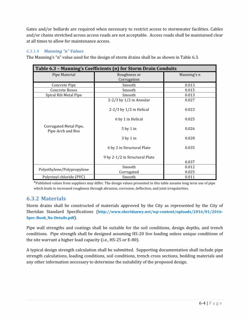
Gates and/or bollards are required when necessary to restrict access to stormwater facilities. Cables and/or chains stretched across access roads are not acceptable. Access roads shall be maintained clear at all times to allow for maintenance access.
Manning “n” Values 6.3.1.4The Manning’s “n” value used for the design of storm drains shall be as shown in Table 6.3.
Table 6.3 – Manning’s Coefficients (n) for Storm Drain Conduits Pipe Material Roughness or
Corrugation Manning’s n
Concrete Pipe Smooth 0.013 Concrete Boxes Smooth 0.015
Spiral Rib Metal Pipe Smooth 0.013
Corrugated Metal Pipe, Pipe-Arch and Box
2-2/3 by 1/2 in Annular
2-2/3 by 1/2 in Helical
6 by 1 in Helical
5 by 1 in
3 by 1 in
6 by 2 in Structural Plate
9 by 2-1/2 in Structural Plate
0.027
0.023
0.025
0.026
0.028
0.035
0.037
Polyethylene/Polypropylene Smooth 0.012 Corrugated 0.025
Polyvinyl chloride (PVC) Smooth 0.011 *Published values from suppliers may differ. The design values presented in this table assume long term use of pipe which leads to increased roughness through abrasion, corrosion, deflection, and joint irregularities.
Materials 6.3.2Storm drains shall be constructed of materials approved by the City as represented by the City of Sheridan Standard Specifications (http://www.sheridanwy.net/wp-content/uploads/2016/01/2016-Spec-Book_No-Details.pdf).
Pipe wall strengths and coatings shall be suitable for the soil conditions, design depths, and trench conditions. Pipe strength shall be designed assuming HS-20 live loading unless unique conditions of the site warrant a higher load capacity (i.e., HS-25 or E-80).
A typical design strength calculation shall be submitted. Supporting documentation shall include pipe strength calculations, loading conditions, soil conditions, trench cross sections, bedding materials and any other information necessary to determine the suitability of the proposed design.
6-4 | P a g e

Access Manholes 6.3.3
General 6.3.3.1Access manholes are required when joining pipes of different sizes, at horizontal or vertical bends in the alignment, at lateral connections, and at the upstream terminus of storm drain mains. City of Sheridan standard manhole details are provided on the City website through the following link: http://www.sheridanwy.net/wp-content/uploads/2015/12/Details-Combined.pdf.
Required Size 6.3.3.2The required minimum manhole size shall be as shown in Table 6.4.
Table 6.4 – Minimum Allowable Manhole Size
Storm Drain Diameter Manhole Diameter
12" to 24" 4’ 27" to 36" 5’
42" 6’ 48" and larger Junction box or Tee Manhole
Larger manhole diameters or a junction box may be required when storm drain alignments are not straight through or where lateral pipes enter the manhole. The number and size of pipes that may be connected to any single manhole is limited in order to maintain the integrity of the structure. For angled connections or those with several pipes on the same plane, a larger manhole than set forth in the Table 6.4 may be required. For structural integrity, minimum undisturbed wall (edge of pipe opening to edge of pipe opening) shall be 8 inches and for 72-inch and larger diameter structures, the minimum undisturbed wall between openings shall be 12 inches; unless otherwise allowed by the manufacturer’s engineer.
Required Spacing 6.3.3.3The maximum manhole spacing along storm drains is as set forth in Table 6.5.
Table 6.5 – Maximum Allowable Manhole Spacing Storm Drain Diameter Maximum Spacing
12” to 36” 400’ 42” to 60” 500’
66” and Larger 600’
Maximum Manhole Depth 6.3.3.4Manhole depths shall not exceed 20 feet without special safety provisions such as intermediate platforms and minimum diameter risers of 48 inches.
Drop Manholes 6.3.3.5The difference between the highest trunkline pipe invert entering a manhole and the invert leaving shall not exceed 24 inches. Manholes exceeding 24 inches of fall shall be designed as drop manholes. Drop manholes with drop heights exceeding six feet shall be designed with high strength (6,000 psi) concrete.
6-5 | P a g e
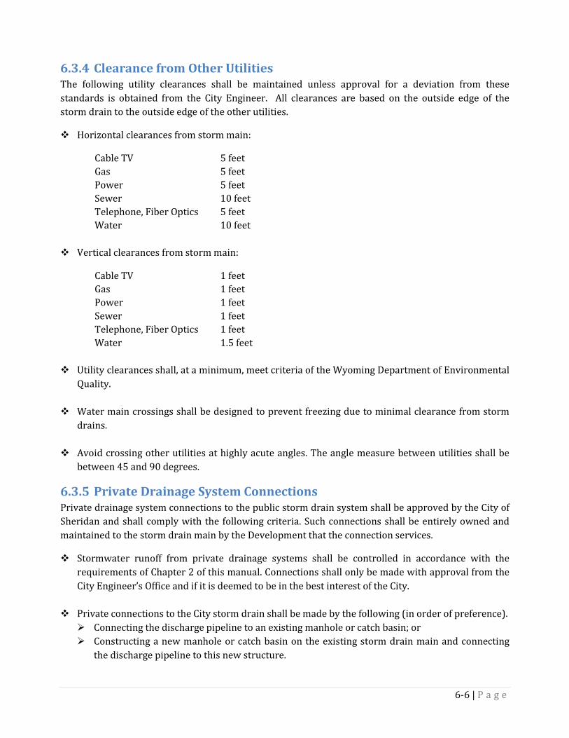
Clearance from Other Utilities 6.3.4The following utility clearances shall be maintained unless approval for a deviation from these standards is obtained from the City Engineer. All clearances are based on the outside edge of the storm drain to the outside edge of the other utilities.
Horizontal clearances from storm main:
Cable TV 5 feet Gas 5 feet Power 5 feet Sewer 10 feet Telephone, Fiber Optics 5 feet Water 10 feet
Vertical clearances from storm main:
Cable TV 1 feet Gas 1 feet Power 1 feet Sewer 1 feet Telephone, Fiber Optics 1 feet Water 1.5 feet
Utility clearances shall, at a minimum, meet criteria of the Wyoming Department of Environmental Quality.
Water main crossings shall be designed to prevent freezing due to minimal clearance from storm drains.
Avoid crossing other utilities at highly acute angles. The angle measure between utilities shall be between 45 and 90 degrees.
Private Drainage System Connections 6.3.5Private drainage system connections to the public storm drain system shall be approved by the City of Sheridan and shall comply with the following criteria. Such connections shall be entirely owned and maintained to the storm drain main by the Development that the connection services.
Stormwater runoff from private drainage systems shall be controlled in accordance with the requirements of Chapter 2 of this manual. Connections shall only be made with approval from the City Engineer’s Office and if it is deemed to be in the best interest of the City.
Private connections to the City storm drain shall be made by the following (in order of preference). Connecting the discharge pipeline to an existing manhole or catch basin; or Constructing a new manhole or catch basin on the existing storm drain main and connecting
the discharge pipeline to this new structure.
6-6 | P a g e
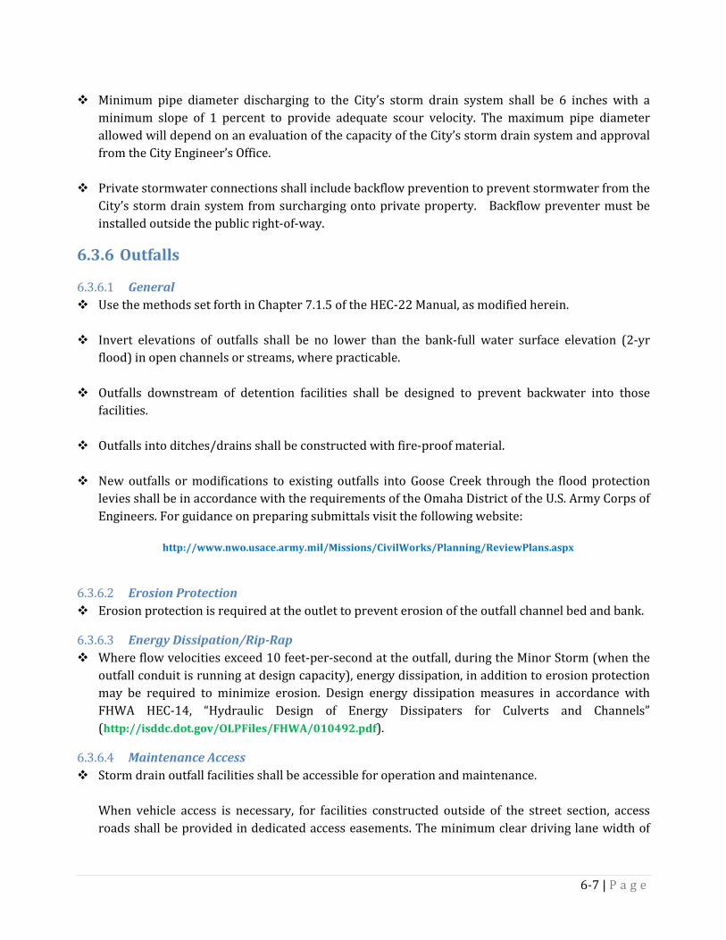
Minimum pipe diameter discharging to the City’s storm drain system shall be 6 inches with a
minimum slope of 1 percent to provide adequate scour velocity. The maximum pipe diameter allowed will depend on an evaluation of the capacity of the City’s storm drain system and approval from the City Engineer’s Office.
Private stormwater connections shall include backflow prevention to prevent stormwater from the City’s storm drain system from surcharging onto private property. Backflow preventer must be installed outside the public right-of-way.
Outfalls 6.3.6
General 6.3.6.1 Use the methods set forth in Chapter 7.1.5 of the HEC-22 Manual, as modified herein.
Invert elevations of outfalls shall be no lower than the bank-full water surface elevation (2-yr
flood) in open channels or streams, where practicable.
Outfalls downstream of detention facilities shall be designed to prevent backwater into those facilities.
Outfalls into ditches/drains shall be constructed with fire-proof material.
New outfalls or modifications to existing outfalls into Goose Creek through the flood protection levies shall be in accordance with the requirements of the Omaha District of the U.S. Army Corps of Engineers. For guidance on preparing submittals visit the following website:
http://www.nwo.usace.army.mil/Missions/CivilWorks/Planning/ReviewPlans.aspx
Erosion Protection 6.3.6.2 Erosion protection is required at the outlet to prevent erosion of the outfall channel bed and bank.
Energy Dissipation/Rip-Rap 6.3.6.3 Where flow velocities exceed 10 feet-per-second at the outfall, during the Minor Storm (when the
outfall conduit is running at design capacity), energy dissipation, in addition to erosion protection may be required to minimize erosion. Design energy dissipation measures in accordance with FHWA HEC-14, “Hydraulic Design of Energy Dissipaters for Culverts and Channels” (http://isddc.dot.gov/OLPFiles/FHWA/010492.pdf).
Maintenance Access 6.3.6.4 Storm drain outfall facilities shall be accessible for operation and maintenance.
When vehicle access is necessary, for facilities constructed outside of the street section, access roads shall be provided in dedicated access easements. The minimum clear driving lane width of
6-7 | P a g e

access roads is 12 feet. Access roads shall have a maximum grade of nine percent and shall be constructed with gravel, pavement, concrete or an appropriate all-season surface.
Gates and/or bollards are required when necessary to restrict access to stormwater facilities. Cables and/or chains stretched across access roads are not acceptable.
6.4 OPEN CHANNEL CONVEYANCES
General 6.4.1New or altered channels shall be lined with grass, rocks or other erosion resistant materials. Concrete or asphalt shall not be used unless approved by the City Engineer.
Design open channels in accordance with the methods provided in Chapter 5 of HEC-22 except as modified herein. Boulevard swales are considered a category of Open Channel Conveyances and are discussed in more detail in Chapter 7.
Clearance 6.4.2Channels shall be located no closer than ten feet from any structure foundation as measured horizontally from the edge of the swale at the top of freeboard elevation. The maximum water surface elevation during the Major Storm event shall be no less than two foot below the finished floor elevation of adjacent residential dwellings and public, commercial, and industrial buildings.
Erosion Control 6.4.3Channel segments shall be designed according to the permissible tractive force (shear stress) methodology set forth in Section 5.3 of HEC-22 and Hydraulic Engineering Circular 15:
http://www.fhwa.dot.gov/engineering/hydraulics/pubs/10009/10009.pdf http://www.fhwa.dot.gov/engineering/hydraulics/pubs/05114/05114.pdf
Both the bare soil condition immediately following construction and the anticipated vegetated conditions of the channel shall be evaluated. If the channel is determined to be unstable during the Minor Storm for either of these conditions, the appropriate long-term, temporary, and transitional linings shall be installed.
Erosion control structures, such as check drops or check dams, may be required to control flow velocities.
The grass species selected for seeding shall conform to requirements set forth in the City of Sheridan Standard Specifications (http://www.sheridanwy.net/wp-content/uploads/2016/01/2016-Spec-Book_No-Details.pdf).
Freeboard Requirements 6.4.4A minimum freeboard of one-foot from the water surface during the Major Storm event to the top of bank shall be provided for open channel conveyances.
6-8 | P a g e

Low-Flow Channels 6.4.5Low flow channels shall be included in the channel cross section to carry low flows and frequent storm events in a confined sub-section of the larger channel.
Friction Factors (n) 6.4.6Use Manning’s roughness factors (n) set forth in Table 5-1 of HEC-22. The design shall consider the channel roughness both immediately after construction and when vegetation is fully established. Roughness factors, which are representative of unmaintained channel conditions, shall be used for the analysis of water surface profiles. Roughness factors, which are representative of well-maintained channel conditions, shall be used to determine maximum velocity.
Side Slopes 6.4.7Side slopes shall be no steeper than 4H:1V for maintained grass-lined channels, 3H:1V for unmaintained native grass-lined channels and 2.5H:1V for riprap-lined channels.
Maintenance Access 6.4.8Provide maintenance access for inspection, mowing operations, and debris removal by conventional equipment along the length of the conveyance channel. The type of equipment needing access is dependent on the size of the channel. Large channels will need access for dump trucks and loaders. For small ditches, foot or pick-up truck access may suffice. Channels may need to be offset within the easement to facility maintenance.
Operation & Maintenance of Private Open Channels 6.4.9Open channels require periodic maintenance. The degree of maintenance is dependent on the location, the type of facility, and the liner material (grass, rock, etc.).
Maintenance of open channels is required to insure the conveyance capacity of the facility is maintained and that channel erosion does not occur. The condition of open channels should be checked on a periodic basis, especially after large storms or extended periods of high flow or immediately following periods of high intensity winds (erosion may occur during high flows, from scour caused by localized debris blockage or from debris blown into the channel). Debris should be removed to prevent channel plugging, channel scour and loss of channel conveyance. Erosion shall be repaired or stabilized.
Vegetated channels shall be maintained to ensure that vegetation does not limit the conveyance capacity of the facility. If conveyance restrictions are apparent, the vegetation should be trimmed to restore capacity.
Emergent vegetation (spirogyra, elodea, watercress, etc.) in conveyance channels may also become a problem if it is allowed to constrict the conveyance capacity of the facility. Vegetation above the ordinary high water mark shall also be monitored primarily for its ability to retain bank stability without reducing channel capacity at maximum design flows.
6-9 | P a g e
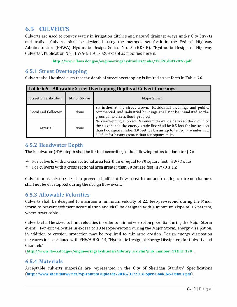
6.5 CULVERTS Culverts are used to convey water in irrigation ditches and natural drainage-ways under City Streets and trails. Culverts shall be designed using the methods set forth in the Federal Highway Administration (FHWA) Hydraulic Design Series No. 5 (HDS-5), “Hydraulic Design of Highway Culverts”, Publication No. FHWA-NHI-01-020 except as modified herein:
http://www.fhwa.dot.gov/engineering/hydraulics/pubs/12026/hif12026.pdf
Street Overtopping 6.5.1Culverts shall be sized such that the depth of street overtopping is limited as set forth in Table 6.6.
Table 6.6 – Allowable Street Overtopping Depths at Culvert Crossings
Street Classification Minor Storm Major Storm
Local and Collector None Six inches at the street crown. Residential dwellings and public, commercial, and industrial buildings shall not be inundated at the ground line unless flood-proofed.
Arterial None
No overtopping allowed. Minimum clearance between the crown of the culvert and the energy grade line shall be 0.5 feet for basins less than two square miles, 1.0 feet for basins up to ten square miles and 2.0 feet for basins greater than ten square miles.
Headwater Depth 6.5.2The headwater (HW) depth shall be limited according to the following ratios to diameter (D):
For culverts with a cross sectional area less than or equal to 30 square feet: HW/D ≤1.5 For culverts with a cross sectional area greater than 30 square feet: HW/D ≤ 1.2
Culverts must also be sized to prevent significant flow constriction and existing upstream channels shall not be overtopped during the design flow event.
Allowable Velocities 6.5.3Culverts shall be designed to maintain a minimum velocity of 2.5 feet-per-second during the Minor Storm to prevent sediment accumulation and shall be designed with a minimum slope of 0.5 percent, where practicable.
Culverts shall be sized to limit velocities in order to minimize erosion potential during the Major Storm event. For exit velocities in excess of 10 feet-per-second during the Major Storm, energy dissipation, in addition to erosion protection may be required to minimize erosion. Design energy dissipation measures in accordance with FHWA HEC-14, “Hydraulic Design of Energy Dissipaters for Culverts and Channels” (http://www.fhwa.dot.gov/engineering/hydraulics/library_arc.cfm?pub_number=13&id=129).
Materials 6.5.4Acceptable culverts materials are represented in the City of Sheridan Standard Specifications (http://www.sheridanwy.net/wp-content/uploads/2016/01/2016-Spec-Book_No-Details.pdf).
6-10 | P a g e
Culvert wall strengths and coatings shall be suitable for the soil conditions, design depths, and trench details. Culvert strength shall be designed assuming HS-20 live load capacity unless unique conditions of the crossing warrant a higher load capacity (i.e., HS-25 or E-80).
When an abrasive bed load is anticipated or when velocities exceed 10 feet per second, protective measures shall be implemented to limit pipe damage. Corrosion, abrasion and other appropriate observations of field conditions shall also be considered in determining appropriate culvert materials and joint types. Corrosion resistance shall be evaluated based on minimum resistivity, pH, sulfate content and chlorine content of the soil and groundwater.
Minimum Size 6.5.5Culverts shall have a minimum diameter or height of 18 inches unless a smaller size is approved by the City of Sheridan.
Allowance for Blockage 6.5.6Culverts crossing arterial streets shall be sized for Major storm events assuming 20 percent of the flow capacity is lost due to blockage. Culverts crossing local and collector streets shall be assumed to be 50 percent blocked to determine overtopping depths during Major storm events.
End Treatments 6.5.7Culverts shall be designed with appropriate end treatments at their inlets and outlets such as flared end sections, headwalls, or wingwalls to provide smooth transitions to/from the drainage channel or ditch and to conform to embankment slopes. In addition to the pipes, end treatments installed within ditches/drains shall be fire-proof. Erosion protection or energy dissipaters shall be provided as necessary to limit erosion due to turbulent flow and high velocities. Depending on the culvert location, a safety grate or trash rack may need to be installed.
Maintenance Access 6.5.8Provide maintenance access to the upstream and downstream ends of culverts for inspection and debris removal.
6.6 BRIDGES Hydraulic sizing for bridges shall conform to the requirements of the Wyoming Department of Transportation (WYDOT) as modified herein.
Freeboard Requirements 6.6.1Minimum clearance between the energy grade line and the lowest bridge girder shall be 1.0 feet for basins up to ten square miles and 2.0 feet for basins greater than ten square miles, to allow for the passage of floating debris during the Major storm.
Allowable Rise 6.6.2The water surface elevation during the Major Storm event upstream of bridges shall not increase due to channel constrictions and hydraulic losses caused by the bridge.
6-11 | P a g e
Scour 6.6.3Estimates of local and long term scour shall be calculated according to methods approved by WYDOT to determine the required abutment protection and establish the required depth of the bridge support structures.
6.7 PUMPING STATIONS Pumping stations are generally not acceptable for controlling stormwater runoff. Exceptions shall be pre-approved by the City Public Works Department. Pumping stations, when allowed, shall be designed in accordance with the criteria presented in Chapter 9 of the HEC-22 Manual as modified herein.
The Developer shall demonstrate that the pump system is the only feasible alternative available to provide drainage. If a deviation for a pump system is approved, the system shall meet the following minimum requirements: Pump systems shall be owned, operated, maintained, repaired, and replaced (as needed) by the
Developer/property owner(s) served by such system.
Each pump shall be capable of discharging the design flow rate for the Major storm.
If a stormwater detention system is not provided, the pump system shall have a storage facility (pond, tank, or vault) sized to hold 25 percent of the total volume of runoff for the developed tributary drainage area for the 2-year, 24-hour design storm.
The pump system shall have dual, alternating pumps with emergency on-site, back-up power supply, and an external alarm system for system failure and high water level indicator.
A safe emergency overflow route shall be provided, if possible.
The pump system shall discharge to an elevation higher than the downstream design water surface elevation to prevent backwater/backflow conditions.
A Maintenance and Operation Schedule shall be prepared and submitted for review.
A note on the approved plan shall stipulate that the private property owner(s) shall be responsible for any and all claims for injuries and damage due to the operation or non-operation of the pump system.
6-12 | P a g e
Chapter 7 - Runoff Control Facilities 7.1 APPLICATION This chapter provides criteria for design of runoff control facilities including detention basins, retention/infiltration basins, and boulevard swales. These facilities are used to control the quantity of runoff discharged from the project site by storing runoff and slowly releasing water through an outlet structure, by evaporation and infiltration, or conveyance measures. These runoff control facilities may also be used in conjunction with water quality treatment facilities discussed in Chapter 8.
7.2 DETENTION BASINS Detention basins can be designed as a standalone facility, also known as a dry basin, where runoff is routed over time until the basin completely drains out. They can also be designed to “stack” on top of water quality facilities such as retention/infiltration basins or wet basins where temporarily stored runoff will drain down to the original wet basin water surface elevation or to the top of the retention/infiltration basin designed to store the water quality volume (WQV). Further details of these water quality facilities are provided in Chapter 8. Detention basins shall be designed to limit the runoff from the site to pre-development rates for the full range of potential storms including the 2-year, 10-year, and 100-year events.
Detention storage is not required for sites less than 10,000 square feet in area or where site improvements result in less than 5,000 square feet of impervious surface. LID techniques are however, recommended for these sites.
Design of detention basins shall follow the procedures presented in Chapter 8 of the HEC-22 Manual, as modified herein (http://www.fhwa.dot.gov/engineering/hydraulics/pubs/10009/10009.pdf).
Groundwater 7.2.1Anticipated groundwater levels must be addressed in the design to ensure that sufficient capacity will be available in the basin, above the historic, seasonally-high water table, for storage of stormwater runoff. For standalone detention basins, the historic, seasonally-high water table level shall be a minimum of three feet below the bottom of basin to avoid saturated conditions which interfere with proper maintenance of the facility.
Further details on required groundwater evaluations and suggested sources of information are provided in Appendix D.
Basin Geometry 7.2.2 Maximum water depth at any time shall not exceed 6 feet for detention basins. The maximum
water depth can exceed 6 feet only in those cases where a detention basin is “stacked” on top of a water quality wet basins or wetland.
Side slopes shall be no steeper than 4H:1V for maintained grass-lined channels, 3H:1V for unmaintained native grass-lined channels and 2.5H:1V for riprap-lined channels.
7-1 | P a g e
The maximum water surface elevation during the Major Storm shall be no less than one foot below
the adjacent ground and two feet below window well, finished floor, top of foundation or any other entry point vulnerable to flooding for residential dwellings and public, commercial, and industrial buildings.
Safety benches should be considered with larger detention basins to provide a shallow area for people and animals that inadvertently enter the open water, to exit the basin.
Maximum Drain-Down Time 7.2.3Detention basins are used to limit discharge from the site to an allowable runoff rate as discussed in Chapter 2. The water surface in the facility shall return to the pre-storm level within 72-hours after cessation of the major storm.
Low-Flow Channels 7.2.4Dry detention basins shall be constructed with low-flow channels that have a capacity of 1 to 3 percent of the Minor Storm inflow rate and with a minimum longitudinal slope of 0.5 percent. The bottom of the basins shall be sloped at a 2 percent minimum grade towards the low-flow channel to facilitate drainage.
Multi-Purpose Use 7.2.5Detention facilities designed for multi-purpose use (sport courts, neighborhood parks, play areas, picnic areas, etc.) are allowed. Multi-use amenities shall be anchored to prevent floatation.
Runoff from more frequent storms shall be stored separately from the multiple use areas. These separate storage areas should, at a minimum, be sized to store the water quality storm volume.
The developer shall make arrangement for maintenance of such amenities unless such responsibility is accepted by the City of Sheridan.
Set Backs 7.2.6 Detention basins shall be located such that: the facility does not interfere with underground utilities or adjacent structures; the top of a cut embankment or the toe of a fill embankment shall be setback at least 5 feet
from property lines; and adequate maintenance and operations access are provided. The geotechnical and hydrogeological report, detailed in Appendix D, shall identify potential
adverse impacts to surrounding soils, groundwater, and adjacent facilities or structures along with methods to mitigate negative impacts, if any.
Water Quality Treatment 7.2.7
Stormwater runoff from the water quality event shall be routed through a sediment trap, sediment forebay, or other appropriate water quality BMP, detailed in Chapter 8, prior to discharging to the detention basin in order to facilitate removal of transported sediments and debris. If other potential
7-2 | P a g e

pollutants such as oils, grease, or fuel (gasoline and diesel) could be present in the site runoff, it may also be necessary to provide added measures to remove these contaminants.
Designing detention basins to serve the secondary benefit of water quality treatment is encouraged. General guidance is provided in Section 10 of the HEC-22 Manual. Further details on the water quality design criteria are provided in Chapter 8.
The facility shall be protected from high sediment loads during construction and until site vegetation has established.
Outlet Control Structures 7.2.8Outlet control structures shall be designed using the criteria and methods set forth in Chapter 8 of the HEC-22 Manual, as modified herein.
Minimum orifice diameter without screening is six inches. Screening shall be provided to prevent blockage for orifices of smaller diameter.
Where safety or debris is an issue, install removable trash and safety racks at outlet orifices, pipes, and weirs.
Design the outlet structure to minimize the potential for clogging. Consider using perforated pipes with gravels as a filter to prevent clogging, where appropriate.
The minimum diameter for outlet conduits shall be 12 inches. Anti-seep collars shall be placed on outlet conduits through embankments.
Emergency Overflow & Spillways 7.2.9Use the criteria set forth in Chapter 8.4.4.4 of the HEC-22 Manual as modified herein. All detention storage facilities shall include a provision for non-erosive control of overflows. Overflows from the Major Storm event shall be directed to a safe discharge path to protect adjacent and downstream properties from damage.
Discharge leaving the site shall be at the same location and have the same characteristics as pre-developed flows. Offsite easements may be required per Table 2.3.
Embankments 7.2.10Embankments shall comply with Dam Safety guidelines as published by the Wyoming State Engineers Office. The maximum embankment height is measured from the downslope toe to the crest of the embankment. Embankments six feet and higher shall be designed and inspected by a licensed civil/geotechnical engineer with expertise in embankment design.
Permit requirements are outlined in Part I, Surface Water, of the Regulations and Instructions. Permits from the State Engineer’s Office are required for any dams (including detention facilities) with a storage volume of 50 ac-ft or greater or a height of 20 feet or greater.
7-3 | P a g e
The Special Application filing procedures apply to flood control reservoirs and dams between 6 feet and 20 feet in height and with an inactive capacity between 20 acre-feet and 50 acre-feet if there is an 18-inch diameter, or larger, uncontrolled outlet pipe.
Dam or detention facilities are exempt from the State Engineer permitting process when they:
Are pit-type or excavated flood control impoundments that are designed with an outlet device that will evacuate the impoundment within 24 hours.
Have a storage capacity of 50 acre-feet or less and a height of 6 feet or less as measured from the downstream toe to the crest of the dam. Under this exemption the outlet pipe must be a minimum of 18 inches in diameter, be uncontrolled and shall totally evacuate the impoundment.
State regulations may be updated or revised periodically. It is the responsibility of the Developer/Owner and the designer to comply with all State requirements for design and permitting.
Vegetation & Landscaping 7.2.11Detention basins shall be landscaped to provide for slope stability, erosion control, and low maintenance. Landscape materials shall be compatible with use in a stormwater detention facility and associated water quality treatment facility. Utilize plant species native to the Sheridan area to the maximum extent practicable. In general, basins shall be irrigated and either seeded or installed with sod to provide an amenity to the community.
Floatable or erodible material (i.e., wood chips, straw mulch, etc.) shall not be allowed within the basin. The interiors of the basin shall be stabilized with gravel, rock, and vegetation.
Vegetation on basin embankments shall be limited to shallow rooted varieties. Points of inflow to the basin shall be armored to prevent erosion.
Maintenance and Maintenance Access 7.2.12 Maintenance shall be performed by the HOA or commercial site owner, unless this responsibility is
accepted by the City. Further details are provided in Appendices E and F.
Maintenance will be required to remove invasive plants and debris accumulated at inlet and outlet structures.
Stormwater detention basin outlet control structures shall be accessible for maintenance and operation. When vehicle access is necessary, access roads shall be provided in dedicated access easements or right-of-way of at least 20 feet wide. The minimum clear driving width of access roads shall be 12 feet and the minimum turn-around radius shall be 25 feet or hammerhead. Access roads shall have a maximum grade of nine percent and shall be constructed with gravel, pavement, concrete or an appropriate all-season surface.
Gates and/or bollards are required when necessary to restrict access to stormwater facilities. Cables and/or chains stretched across access roads are not acceptable. Access roads shall be maintained clear at all times to allow for maintenance access.
7-4 | P a g e

7.3 RETENTION/INFILTRATION BASINS Retention/Infiltration Systems are generally not acceptable for disposing of stormwater runoff and the Developer shall demonstrate that this is the only feasible alternative available to provide drainage. Exceptions shall be pre-approved by the City Public Works Department. If a deviation for an infiltration system is approved, the system shall meet the requirements set forth in this section.
Retention/Infiltration facilities are used to fully retain the site runoff volume where no viable outfall exists and shall be designed to fully store the post-development site runoff from the Major Storm event (100-year, 24-hour storm). The open water surface of the retention facility shall return to the pre-storm level within 72-hours after cessation of the Major Storm.
Retention basins and infiltration basins are very similar in function and consist of a basin with the only means of emptying being through evaporation, evapotranspiration and infiltration. Retention and Infiltration basins are used to control runoff, but are also used to provide water quality treatment by filtration into the soil. This section discusses the design criteria for retention/infiltration basins for both runoff control and water quality treatment of the water quality volume (WQV). Further details of the water quality design are discussed in Chapter 8.
Retention/infiltration basins can either be constructed as open systems or subsurface systems. Open systems typically includes excavation of a basin designed to slowly infiltrate the collected runoff into the underlying soil. Subsurface retention/infiltration basins take the form of boulder pits, vault systems, and injection wells which are typically used on sites with limited available space.
Retention storage is not required for sites less than 10,000 square feet in area or where site improvements result in less than 5,000 square feet of impervious surface. LID techniques are however, recommended for these sites.
Geotechnical/Hydrogeological Evaluation 7.3.1A geotechnical/hydrogeological evaluation conducted in accordance with Appendix D is required to support the design of retention/infiltration basins for both runoff control and water quality treatment purposes. The evaluation shall be conducted at and below the bottom elevation to minimum depths specified at the location of the proposed basin to characterize native soils, groundwater conditions, and adjacent facilities and structures. The assessment shall demonstrate the feasibility of infiltration and to assess potential risks and mitigation options of stormwater infiltration. The assessment will be conducted by a professional engineer (PE) or profession geologist (PG) licensed in the State of Wyoming and with experience collecting and analyzing hydrogeological data.
The Developer shall demonstrate through site specific: 1) infiltration testing; 2) soil logs; and 3) a written opinion of a PE or PG that sufficiently permeable soils exist for an infiltration system meeting the requirements herein, to function properly.
The infiltration rate shall be measured at a depth equal to the proposed bottom grade of the facility. A factor of safety of 2.0 shall be applied to the measured infiltration rate in arriving at the design infiltration rate. The procedure presented in Appendix H shall be followed in determining infiltration rates.
7-5 | P a g e
The Geotechnical/Hydrogeological report shall identify the appropriate proximity of infiltration system in relation to adjacent facilities and structures. Developer shall collect sufficient data to characterize the hydrogeological conditions of the site, potential impacts on groundwater levels, structures and facilities both within and outside the limits of development, as well as methods for mitigating these impacts.
Limitations 7.3.2 Retention/Infiltration basins may not be approved for use where hydrogeological conditions exist
that indicate the potential for infiltrated stormwater to result in adverse impacts to on- or off-site facilities or structures and where no reasonable mitigation options exist.
Not appropriate for use with tight clays or other soils with low infiltration rates or in areas with a shallow water table.
Groundwater 7.3.3The depth to the historic, seasonally-high water table, bedrock, hardpan or other impermeable layer shall be no less than three feet below the bottom of the retention/infiltration basin.
Further details of required groundwater evaluations are provided in Appendix D.
Basin Geometry 7.3.4 Maximum water depth at any time shall not exceed 6 feet for an open retention/infiltration basin.
Safety benches should be considered with larger retention/infiltration basins to provide a shallow area for people and animals that inadvertently enter the open water, to exit the basin.
Open retention/infiltration basin side slopes shall be 4H:1V or flatter for maintained grass-lined channels, 3H:1V for unmaintained native grass-lined channels and 2.5H:1V for riprap-lined channels.
Embankment fill slopes shall be no steeper than 3H:1V and preferably 4H:1V or flatter.
Subsurface retention/infiltration basins shall be sized based upon the porosity of the fill material within the facility and not on the void ratio of the fill material.
The maximum water surface elevation during the Major Storm shall be no less than one foot below the adjacent ground and 2 feet below window well, finished floor, top of foundation or any other entry point vulnerable to flooding for residential dwellings and public, commercial, and industrial buildings.
Subsurface infiltration facilities shall be provided with emergency surface storage of at least 10 percent of the Major (100-year, 24-hour) storm volume, with a minimum storage depth of 0.5 feet, on the site, prior to discharging runoff to a safe overflow route. The overflow route shall have adequate capacity for the 100-year flow, in the event of system failure. Water ponding in the emergency surface storage shall be used by the owner as an indication of problems with the infiltration system.
7-6 | P a g e
Maximum Drain-Down Time 7.3.5 Retention/Infiltration basins shall completely drain the captured runoff from the Major (100-year,
24-hour) storm within 72-hours after cessation of the storm.
If the retention/infiltration basin is used in combination with a detention basin to control the quantity of runoff, the total draw-down time for the facility shall not exceed 72-hours.
Multi-Purpose Use 7.3.6Retention/infiltration facilities designed for multi-purpose use (sport courts, neighborhood parks, play areas, picnic areas, etc.) may be allowed where the hydrogeological conditions are appropriate. Multi-use amenities shall be anchored to prevent floatation.
Runoff from more frequent storms shall be stored separately from the multiple use areas. At a minimum, use the water quality storm to size these separate storage areas.
Subsurface infiltration areas shall not be: 1) driven on by vehicles or equipment, or 2) used for material or equipment storage or stockpiles. The developer shall make arrangement for maintenance of such amenities unless such responsibility is accepted by the City of Sheridan.
Set Backs 7.3.7 Retention/Infiltration basins shall be located: Such that the facility does not interfere with underground utilities; No closer than 20 feet from any structure, property line, protected area or another infiltration
system; Such that adequate access for maintenance and operations are provided; and The findings from the geotechnical and hydrogeological investigation may dictate other
setback requirements.
Water Quality Treatment 7.3.8Stormwater runoff from the water quality event shall be routed through a sediment trap, sediment forebay, or other appropriate water quality BMP, listed in Chapter 8, prior to discharging to the retention/infiltration basin, in order to facilitate removal of transported sediments and debris. If other potential pollutants such as oils, grease, or fuel (gasoline and diesel) could be present in the site runoff, it may also be necessary to provide added measures to remove these contaminants. More information on these BMPs is discussed in Chapter 8 and/or Appendix A of this manual.
The sediment forebay to Retention/Infiltration basins shall have sufficient capacity to control the entire WQV (see Chapter 8) and construction BMPs shall be employed to protect the basin from unusually high sediment loads during construction and until site vegetation is established.
If the retention/infiltration basin is used in combination with a detention basin to control the quantity of runoff, the total draw-down time for the facility shall not exceed 72-hours.
7-7 | P a g e
Maintenance & Maintenance Access 7.3.9 Maintenance shall be performed by the HOA or commercial site owner, unless this responsibility is
accepted by the City. Further details are provided in Appendices E and F.
Infiltration facilities shall be accessible for operation and maintenance. When vehicle access is necessary, for facilities constructed outside of the street section, access roads shall be provided in dedicated access easements of 20-foot minimum width. The minimum clear driving width of access roads shall be 12 feet and the minimum turn-around radius shall be 25 feet or hammerhead. Access roads shall have a maximum grade of nine percent and shall be constructed with gravel, pavement, concrete or an appropriate all-season surface.
Approval of retention/infiltration systems shall obligate the owner to repair, replace, or reconstruct the system if it fails to operate as designed. The maintenance and operation schedule for retention/infiltration systems shall include such a provision.
Failure to maintain retention/infiltration systems will be subject to the terms set forth in the Development Agreement for the subdivision or commercial site.
7.4 Boulevard Swales Boulevard swales are primarily used in subdivisions without conventional curb/gutter street sections. Boulevard swales are designed to control runoff by either collecting runoff from the street and adjacent areas and storing/infiltrating the runoff into the soil or by conveying runoff to a detention/retention facility. Boulevard swales typically have contributing drainage areas of less than 1 acre. Boulevard swales shall be designed to accommodate the worst-case runoff scenario which is typically immediately following initial construction of the development, prior to build-out. Boulevard swales should not be confused with water quality swales discussed in Chapter 8, which are used for water quality treatment and designed for a water quality flow (WQF).
Locations 7.4.1 Boulevard swales are commonly placed along roadways or property lines in a manner that
integrates the swale with adjacent infrastructure, landscaping and water quality features.
Boulevard swales shall be located within the right-of-way or dedicated storm drainage easement.
Geotechnical/Hydrogeological Evaluation 7.4.2Geotechnical/Hydrogeological investigations for boulevard swales designed to store/infiltrate stormwater shall follow the same criteria as retention/infiltration basins described in section 7.3.1. The geotechnical/hydrogeological investigation shall be conducted at and below the bottom elevation and location of the proposed swale. The historic, seasonally-high water table level shall be a minimum of three feet below the bottom of the boulevard swale. See Appendix D and H for additional requirements.
7-8 | P a g e
Basin Geometry 7.4.3 The boulevard swale shall use a trapezoidal cross section with side slopes no steeper than 4H:1V
for maintained grass-lined channels, 3H:1V for unmaintained native grass-lined channels and 2.5H:1V for riprap-lined channels.
The minimum bottom width shall be 1-ft.
The swale must be designed to control runoff in accordance with the requirements presented in Chapter 2.
The maximum water surface elevation during the Major Storm shall be no less than one foot below the adjacent ground and two feet below window well, finished floor, top of foundation or any other entry point vulnerable to flooding for residential dwellings and public, commercial, and industrial buildings.
Maximum Drain-Down Time 7.4.4 Boulevard swales used for retention shall be designed to fully drain within 72-hours after
cessation of the Major (100-year, 24-hour) storm.
Culverts 7.4.5 Culverts installed in boulevard swales shall be designed in accordance with the requirements of
Section 6.5 of this manual. Associated drive approaches shall be constructed in accordance with the City of Sheridan standard drawing for drive approaches.
Landscaping and Vegetation 7.4.6 Boulevard swales shall be either planted with vegetation sufficient to provide full ground coverage
or shall be landscaped with rock.
Vegetation shall be comprised of drought-tolerant grasses or shall be supplemented with a sprinkler system.
Maintenance & Maintenance Access 7.4.7 Boulevard swales shall be protected from high sediment loads during construction and until
vegetation is established in the swale and on adjacent areas contributing runoff. This may require periodic cleaning of the boulevard swale until vegetation is fully established.
Maintenance for swales and associated culverts shall be addressed in the HOA or by the adjacent property owner and shall follow the requirements of Appendix E and F and the Development Agreement. Maintenance requirements shall address vegetation heights, mowing, watering, fertilizing and frequency for sediment removal and erosion repairs.
If access from the adjacent public right-of-way is not available, an access easement to the swale shall be provided to facilitate inspection, monitoring, and maintenance. Appropriate access shall be considered when accounting for maintenance of culverts within the swale.
7-9 | P a g e

Failure to maintain boulevard swales will be subject to the terms set forth in the Development
Agreement.
7-10 | P a g e

Chapter 8 - Permanent Water Quality Treatment 8.1 APPLICATION The character of the urban landscape affects both the quantity and quality of stormwater discharge to receiving waters during each storm. The quality of stormwater runoff from developed lands and urbanized areas can be impacted by some or all of the sources and contaminants indicated in Table 8.1. Increasing impermeable areas such as rooftops, parking lots, and paved surfaces impacts stormwater quantity and quality by decreasing the opportunity for stormwater to infiltrate and percolate into the ground.
Table 8.1 – Potential Sources of Stormwater Pollutants Source Contaminant
Vehicles, Machinery, and Industry Metals, Lubricants, Solvents, Paints Lawn Care, Gardening, Agriculture Lands Pesticides, Herbicides, Fertilizers Household Chemicals Cleaners, Chlorine Paints, Solvents Detergents, Disinfectants Pets and Animals Fecal Material, Organic Wastes Parking Lots and Streets Oil, Grease, Automotive Fluids, Sediments
The 1987 amendment to the Clean Water Act requires that operators of municipal separate storm sewer systems (MS4s) implement controls to the maximum extent practicable, including stormwater management for developments, stormwater pollution prevention for industrial activities, sediment and erosion control for construction activities, and TMDL implementation. Stormwater discharge for the City of Sheridan is covered under the general MS4 permit for the State of Wyoming. Additionally, the 2010 final TMDL report for the Goose Creek Watershed included recommended actions for the City of Sheridan to achieve reductions in contaminant discharge as measured by Total Suspended Solids (TSS) and pathogen loading (SWCA, September 2010).
The recommended actions from the 2010 TMDL report include continued implementation of the following: 1) routine maintenance to remove sediment; 2) installation of mechanical treatment devices and sediment traps; 3)requirements of erosion and sediment control for construction activities; 4) stormwater inlet marking; 5) public education and outreach; and 6) planning for future capital improvements to address water quality treatment. The TMDL report also recommended implementation of additional measures such as infiltration basins, bioretention swales, rain gardens, porous pavement, wet basins, and wetlands.
This chapter presents the requirements for the implementation and use of permanent BMPs for long-term stormwater quality control. Compliance with this section does not require water quality monitoring, or quantitative estimates of pollutant load removal. However, the use of a performance-based approach whereby the principles and objectives of stormwater pollutant control are addressed and applied is recommended. The goal of the water quality requirements is to achieve a 92% reduction in pathogens and a 76% reduction in TSS for the City of Sheridan MS4 stormwater outfalls.
8-1 | P a g e
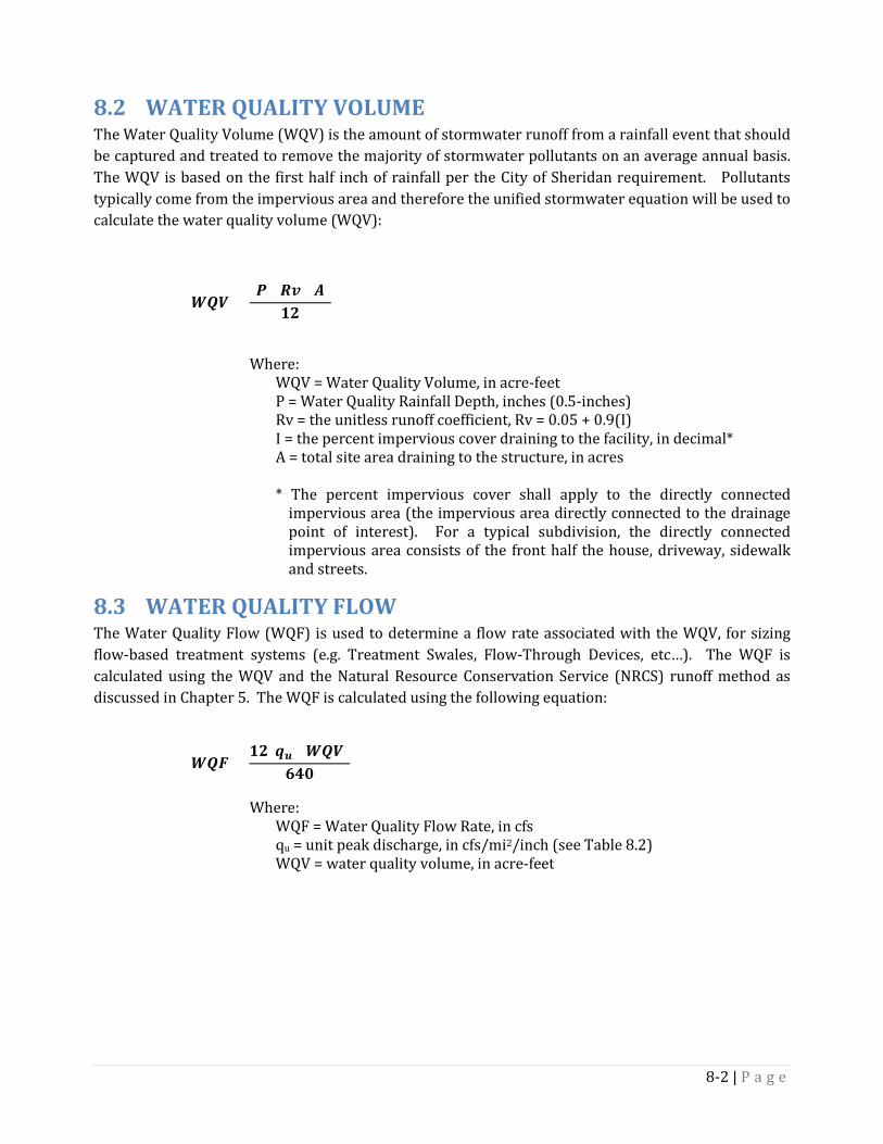
8.2 WATER QUALITY VOLUME The Water Quality Volume (WQV) is the amount of stormwater runoff from a rainfall event that should be captured and treated to remove the majority of stormwater pollutants on an average annual basis. The WQV is based on the first half inch of rainfall per the City of Sheridan requirement. Pollutants typically come from the impervious area and therefore the unified stormwater equation will be used to calculate the water quality volume (WQV):
𝑾𝑾𝑾𝑾𝑾𝑾 =(𝑷𝑷)(𝑹𝑹𝑹𝑹)(𝑨𝑨)
𝟏𝟏𝟏𝟏
Where:
WQV = Water Quality Volume, in acre-feet P = Water Quality Rainfall Depth, inches (0.5-inches) Rv = the unitless runoff coefficient, Rv = 0.05 + 0.9(I) I = the percent impervious cover draining to the facility, in decimal* A = total site area draining to the structure, in acres * The percent impervious cover shall apply to the directly connected
impervious area (the impervious area directly connected to the drainage point of interest). For a typical subdivision, the directly connected impervious area consists of the front half the house, driveway, sidewalk and streets.
8.3 WATER QUALITY FLOW The Water Quality Flow (WQF) is used to determine a flow rate associated with the WQV, for sizing flow-based treatment systems (e.g. Treatment Swales, Flow-Through Devices, etc…). The WQF is calculated using the WQV and the Natural Resource Conservation Service (NRCS) runoff method as discussed in Chapter 5. The WQF is calculated using the following equation:
𝑾𝑾𝑾𝑾𝑾𝑾 =𝟏𝟏𝟏𝟏(𝒒𝒒𝒖𝒖)(𝑾𝑾𝑾𝑾𝑾𝑾)
𝟔𝟔𝟔𝟔𝟔𝟔
Where:
WQF = Water Quality Flow Rate, in cfs qu = unit peak discharge, in cfs/mi2/inch (see Table 8.2) WQV = water quality volume, in acre-feet
8-2 | P a g e
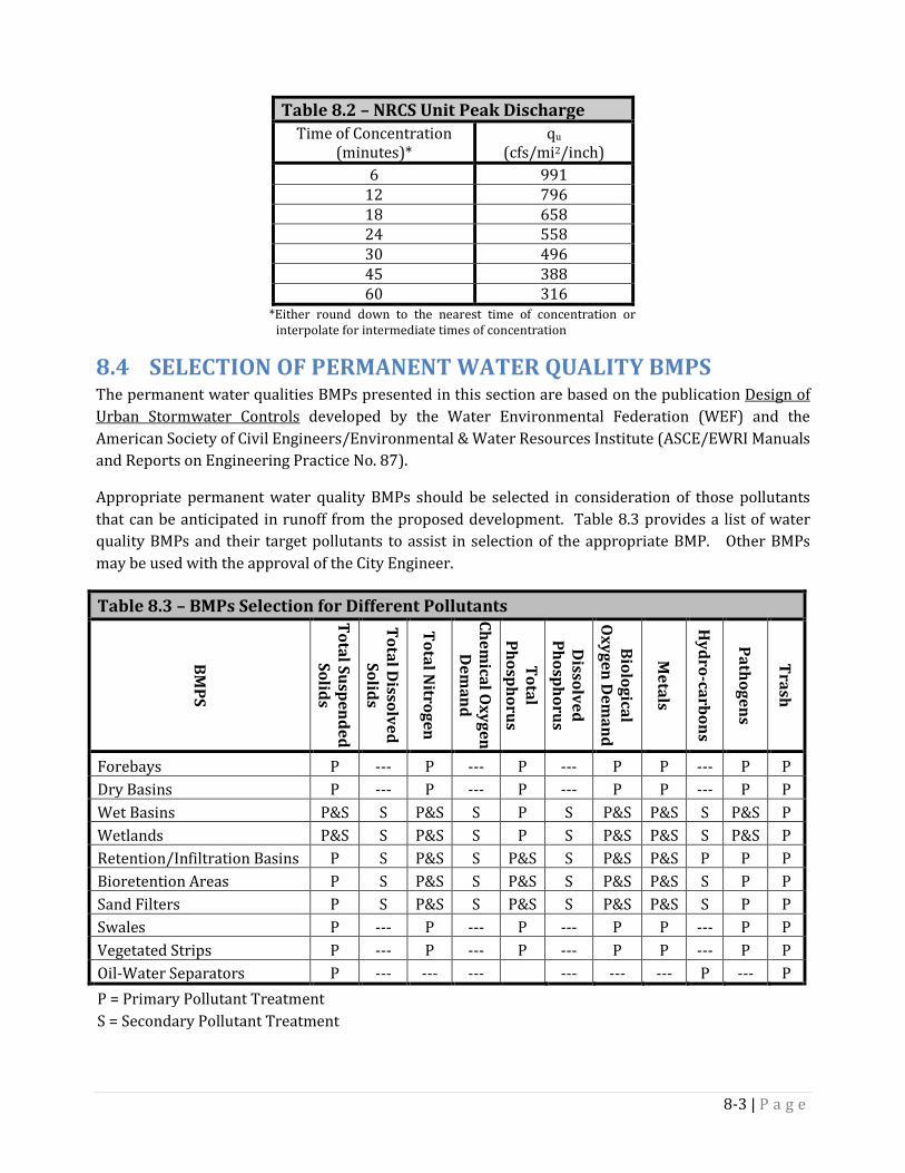
Table 8.2 – NRCS Unit Peak Discharge Time of Concentration
(minutes)* qu
(cfs/mi2/inch) 6 991
12 796 18 658 24 558 30 496 45 388 60 316
*Either round down to the nearest time of concentration or interpolate for intermediate times of concentration
8.4 SELECTION OF PERMANENT WATER QUALITY BMPS The permanent water qualities BMPs presented in this section are based on the publication Design of Urban Stormwater Controls developed by the Water Environmental Federation (WEF) and the American Society of Civil Engineers/Environmental & Water Resources Institute (ASCE/EWRI Manuals and Reports on Engineering Practice No. 87).
Appropriate permanent water quality BMPs should be selected in consideration of those pollutants that can be anticipated in runoff from the proposed development. Table 8.3 provides a list of water quality BMPs and their target pollutants to assist in selection of the appropriate BMP. Other BMPs may be used with the approval of the City Engineer.
Table 8.3 – BMPs Selection for Different Pollutants
BMPS
Total Suspended Solids
Total Dissolved
Solids
Total Nitrogen
Chemical O
xygen D
emand
Total Phosphorus
Dissolved
Phosphorus
Biological O
xygen Dem
and
Metals
Hydro-carbons
Pathogens
Trash
Forebays P --- P --- P --- P P --- P P Dry Basins P --- P --- P --- P P --- P P Wet Basins P&S S P&S S P S P&S P&S S P&S P Wetlands P&S S P&S S P S P&S P&S S P&S P Retention/Infiltration Basins P S P&S S P&S S P&S P&S P P P Bioretention Areas P S P&S S P&S S P&S P&S S P P Sand Filters P S P&S S P&S S P&S P&S S P P Swales P --- P --- P --- P P --- P P Vegetated Strips P --- P --- P --- P P --- P P Oil-Water Separators P --- --- ---
--- --- --- P --- P
P = Primary Pollutant Treatment S = Secondary Pollutant Treatment
8-3 | P a g e
8.5 FOREBAYS A forebay is a pre-treatment facility that is typically an in line unit designed to slow stormwater runoff and settle out coarse sediment. Forebays are typically used to extend the useful life of a downstream primary treatment control and to minimize the extent of maintenance. Forebays are typically excavated pits or cast structures designed to slow incoming stormwater runoff and settle suspended solids. Forebays may be dry or wet but must be able to be dewatered.
Application & Limitations 8.5.1Forebays are pretreatment units compatible with an array of other stormwater BMPs such as wet and dry basins, swales, and wetlands. Forebays are typically not considered a stand-alone treatment method. Forebays are typically installed in areas where there are high sediment loads requiring frequent cleaning.
Frequent maintenance is required to preserve storage volume and avoid re-suspending and flushing of sediment.
The bottom of the forebay should be a minimum of 3-ft above the historic, seasonally-high water table.
Design 8.5.2
General 8.5.2.1 The forebay shall be sized to provide sediment storage of roughly 20% of the WQV.
The forebay shall be sized to have a minimum storage capacity above the sediment storage of 15%
of the WQV.
Forebays should be designed to withstand anticipated velocities during 2 and 10-year storms without scouring to avoid re-suspension of settled particles. Flow velocities during the minor storm should generally be less than 4 fps.
Forebays generally have depths range between 3 and 6 ft.
Side slopes should be no steeper than 3:1 and preferably 4:1 or flatter. Install a sediment depth indicator to identify when the forebay needs to be cleaned and to what
depth cleaning shall occur.
Outlet Structure 8.5.2.2 The forebay can be separated from the primary BMP by one of the following means: A lateral sill with wetland vegetation; Two basins in a series; Differential pool depth; A retaining wall; and, Horizontal rock filter or check dam laterally across the permanent pool.
8-4 | P a g e
The outlet structure should be sized to handle the WQF and also safely pass the minor and major storm events.
Safety Considerations 8.5.3 Size the forebay and spillway between the forebay and primary BMP to prevent the forebay from
overflowing to adjacent property and to protect the basin’s embankments.
On large forebays, include a littoral zone around the perimeter of the forebay to promote the growth of emergent vegetation along the shoreline and deter individuals from wading.
Access & Maintenance 8.5.4When vehicle access is necessary, for facilities constructed outside of the street section, access roads shall be provided in dedicated access easements of 20-foot minimum width. The minimum clear driving lane width of access roads is 12 feet. Access roads shall have a maximum grade of nine percent, shall be constructed with gravel, pavement, concrete or an appropriate all-season surface, and shall be accessible to vacuum trucks where appropriate for maintenance.
8.6 DRY BASIN A dry basin is the same as the detention basin discussed in Chapter 7 for water quantity control. A dry detention basin can be modified to provide water quality treatment by modifying the outlet structure to reduce the discharge rate and extend the detention time to promote sediment removal for the WQV. Design of dry basins shall follow the design criteria presented in Section 7.2 – Detention Basins, as modified herein.
Minimum Drain-Down Time 8.6.1Dry basins are used to limit discharge and increase the hydraulic retention time to maximize sediment deposition while the basin is draining out. The outlet structure should be sized to limit the drain-out time of the WQV to a minimum of 48 hours. The outlet should be sized to empty less than 50% of WQV in the first one-third of the design drawdown period.
The facility will be required to fully drain within 72-hours after cessation of the Major (100-year, 24-hour) storm.
8.7 WET BASIN A wet basin is an artificial lake or pond designed to promote sedimentation of particulate matter and other pollutants. Wet basins provide for water quality treatment and are typically constructed with detention storage “stacked” on top to provide runoff control.
Application & Limitations 8.7.1 Wet basins are considered a main treatment method for pollutants and should be constructed with
an associated forebay for pretreatment. These basins should be constructed in locations and in soils that will allow for a permanent pool of water for the majority of the year.
Need a dependable source of water such as a perennial inflow,, groundwater, and/or supplemental irrigation water to maintain a permanent pool.
8-5 | P a g e
Must evaluate impacts on adjacent land use due to potential seepage.
Attraction of waterfowl must be considered.
Lining of the pond may be required to minimize seepage losses.
Design 8.7.2
General 8.7.2.1 Provide storage for the WQV above the permanent pool elevation.
Aeration will typically be required for wet ponds.
Should be designed to have a WQV drain-down time to the permanent pool elevation between 48
and 72 hours.
If the wet basin is also designed to control runoff quantity for the Minor and Major storm events, the combined drain-down time should not exceed 72-hours.
The depth of the wet basin should typically be between 6 and 12-feet deep.
Side slopes along the shore line should be no steeper than 4:1.
Include a wetland vegetation bench along the shoreline. This bench should be at least 10-ft wide with a water depth of 0.5 to 1.0 ft. The total area of the vegetation bench should be 25 to 50% of the permanent pool water surface area.
Outlet Structure 8.7.2.2 The outlet structure should be sized to empty less than 50% of WQV in the first one-third of the
drain-down time (e.g., 16-hours for the 48-hr draw-down or 24-hours for the 72-hr draw-down).
Design outlet structure to prevent clogging from debris. Consider using perforated pipes and gravels as a filter to prevent clogging where appropriate.
The outlet structure should be sized to handle the WQF and to also safely pass the outflow during the Minor and Major storms.
A water-tight gate should be used for the outlet structure to allow periodic draining of the permanent pool for maintenance.
An emergency spillway should be included for passage above the design storm runoff, to prevent damage to the embankment.
8-6 | P a g e

Safety Considerations 8.7.3 Place trash and safety racks at outlet orifices, pipes, and weirs.
Access & Maintenance Features 8.7.4 When vehicle access is necessary, for facilities constructed outside of the street section, access
roads shall be provided in dedicated access easements with a minimum width of 20 feet. The minimum clear driving lane width of access roads is 12 feet. Access roads shall have a maximum grade of nine percent and shall be constructed with gravel, pavement, concrete or an appropriate all-season surface.
8.8 WETLANDS Wetlands generally consist of shallow pools that store stormwater between events and promote the growth of rooted vegetation such as reeds, rushes, willows, and cattails. Wetland can treat a wide array of pollutants through sedimentation and other physical, chemical, and biological processes. Wetlands shall only be used with the approval of the City Engineer. If constructed wetlands are proposed, a hydrogeological assessment must be conducted, as described in Section 7.3 and Appendix D. The design of the wetlands shall be performed by engineers or ecologists with specialized experience in the design, construction, and maintenance of wetlands.
8.9 RETENTION/INFILTRATION BASINS Retention/infiltration basins consist of open or subsurface systems where runoff is captured and discharged by evaporation and infiltration into the native soil. Pollutants are captured within these facilities and either settle-out or are filtered through the infiltration process. Chapter 7.3 provides design criteria for these facilities.
8.10 BIORETENTION AREAS & BIORETENTION SWALES Bioretention areas and swales capture and temporarily pond the water quality volume (WQV) in shallow swales or landscaped areas. The WQV is filtered through a filter media to remove pollutants from stormwater runoff. The filtered runoff is typically collected and returned to the down gradient conveyance system, though it can also infiltrate into the surrounding soil in areas of permeable soils and low water tables.
Application & Limitations 8.10.1 Bioretention areas and swales are considered a main treatment of pollutants. Bioretention
systems shall be applied to small-scale projects of 5 acres or less. Multiple filtering systems can be used for larger areas.
Bioretention areas are typically designed on sites with gentle slopes. Steep slopes present problems with embankment height, excavation depth, groundwater breakout, or slope stability.
Stormwater runoff carrying high concentrations of oil and grease impairs the treatment capability. Oil-water separator shall be applied as pretreatment in this situation.
8-7 | P a g e

Bioretention systems are susceptible to clogging by sediment and therefore consideration should be given to use of an associated pre-sedimentation forebay.
Bioretention systems should not receive continuous base flows.
The bottom of the Bioretention basins shall be at least 3 feet above the historic, seasonally-high water table.
Bioretention areas and swales are not intended to provide runoff control. An overflow structure or a flow splitter structure shall be provided to convey flow from storms larger than the WQV to flow control facilities.
Design 8.10.2
General 8.10.2.1Ponding area provides for surface storage of stormwater runoff before it filters through the filter bed. The ponding area shall contain the entire volume associated with the Water Quality Volume. The ponding depth shall be designed to be 12 to 24 inches above the filter bed.
Surface Cover 8.10.2.2 Bioretention system shall have a 2 to 4 -inch landscape layer placed above the filter media to
protect the soil bed from erosion. The landscape layers include the following: Mulch: Mulch enhances plant survival, suppresses weed growth, and pre-treats runoff before it
reached the filter media. Shredded, aged, hardwood bark mulch makes a very good surface cover;
Turf grasses; Turf grasses (fine fescue, tall fescue) are typical used for bioretention applications; and,
River stone or pea gravel: Stone or gravel are not recommended in parking lot application because they increase soil temperatures and have low water holding capacity.
Filter Media 8.10.2.3 Planting soils media shall consist of a sandy loam, loamy sand, or loam texture per USDA textural
triangle with a clay content ranging from 0 to 5%. In addition, the planting soil must have a 3 to 5% organic content. The recommended planting soil media mixture is: 50 - 70 % of permeable sand and fine gravel mixture; 5 - 20 % of large organic particles such as wood chips or shredded mulch; 10 -25 % of native soil preferably a loam; and, 10 - 20% of fine organic material.
Bioretention basin design shall use premixed certified media from a vendor that meets the following requirements for phosphorus contend, cation exchange (CEC), and media filtration; The recommend P-index value is between 10-30.
The minimum filter media depth shall be between 24 to 48 inches; and,
8-8 | P a g e
Install a separation geotextile around media to prevent fines from entering the media.
Outlet Structure 8.10.2.4 Outflow from bioretention swales can be through infiltration into the underlying native soils or to
an underdrain collection system.
The underdrain collections system is typically constructed of a perforated pipe installed within a layer of 3/8" washed pea gravel or 3/4" crushed gravels. The extents of the perforated pipe should extend along the bottom of the Bioretention area and transition to non-perforated pipe to carry the flow to downstream stormwater facilities. Underdrains shall be included in the design when subsoil infiltration rates are below 1.0
inch/hr; The pipe spacing shall be at a maximum of 10 feet on center and a minimum grade of 0.5%
must be maintained; and, All underdrain systems shall be day-lighted to an outfall structure.
Planting Requirements 8.10.2.5 A dense vegetative cover shall be established over the contributing drainage area before runoff can
be accepted into the facility.
A landscape plan shall be provided for the bioretention area in the drainage report.
Consideration shall be given for winter conditions; i.e., salt and sand-tolerant plants and reduced resistance to flows during spring melt.
Planting recommendations for bioretention facilities can be found through the Wyoming Natural Resource Conservation Service. Native plant species should be specified over non-native species; A selection of trees with an understory of shrubs and herbaceous material should be provided; Woody vegetation should not be specified at inflow locations; Trees should be planted primarily along the perimeter of the facility but are not to interfere
with maintenance; Plants should be selected based on specified zone of hydric tolerance and must be capable of
surviving both wet and dry conditions; and "Wet footed" species should be planted near the center, whereas upland species are better
near the edge.
Access & Maintenance Features 8.10.3 When vehicle access is necessary, for facilities constructed outside of the street section, access
roads shall be provided in dedicated access easements with a minimum width of 20 feet. The minimum clear driving lane width for access roads is 12 feet. Access roads shall have a maximum grade of nine percent and shall be constructed with gravel, pavement, concrete or an appropriate all-season surface.
8-9 | P a g e

Maintenance Criteria 8.10.4 The maintenance access shall be designed such that all areas of the bioretention area can be easily
accessed, and shall be designed to allow vehicles to turn around.
Successful establishments of bioretention areas requires certain tasks be undertaken in the first year. Initial inspections: For the first six months following construction, the site should be inspected
a least twice after storm events that exceed 0.25"; Spot Reseeding: Inspector should look for bare or eroding areas in the contributing drainage or
around the bioretention area, and make sure that they are immediately stabilized; Fertilization: One-time, spot fertilization may be need for initial plantings; Watering: Watering is needed once a week during the first two month, and then as need during
the first growing season, depending on rainfall; and, Remove and replace dead plants: Since up to 10% of plant stock may die off in the first year,
construction contracts should include a care and replacement warranty to ensure vegetation is properly established and survives during the first growing season following construction.
8.11 SAND FILTERS Surface and subsurface sand filters use clean sand or gravel as the filter media. Stormwater runoff is typically directed to a forebay and then into a filtering cell where it flows vertically through the sand media. At that point, water can infiltrate into the ground or be collected and sent to receiving waters or to the storm drainage system. In a subsurface sand filter, both the forebay and filtering cell are located underground in a vault-type structure.
Application & Limitations 8.11.1 Sand filters are typically used for drainage area less than 5 acres.
Not recommended for high sediment load areas.
The filtering cell must be relatively flat to promote uniform surface ponding.
Surface sand filters can have vegetation growing on the top of the media with the installation of
thin layer of organic material or topsoil. Soil layer over sand filter may produce limiting hydraulic conductivity.
Design 8.11.2
General 8.11.2.1 Place permeable geotextile along the top, walls and bottom of the sand media.
The filter should be a minimum 3-ft above the historic, seasonally-high water table
Must install a forebay upstream of the sand filter
8-10 | P a g e
Provide enough storage above the sand filter media to store the entire WQV.
The thickness of the sand media (dSF) shall be between 18-inch and 24-inches.
The bottom of the cell is considered the surface area for the sand media.
Side slopes should be no steeper than 2.5:1 and preferably 3:1 or flatter.
The surface area for the sand media is based on the following equation:
𝑨𝑨𝑺𝑺𝑾𝑾 = (𝑾𝑾𝑾𝑾𝑾𝑾)�𝒅𝒅𝑺𝑺𝑾𝑾
𝑲𝑲𝟏𝟏 (𝒉𝒉𝑺𝑺𝑾𝑾 + 𝒅𝒅𝑺𝑺𝑾𝑾)𝒕𝒕𝑺𝑺𝑾𝑾
�
Where:
ASF = Surface Area for Sand Media, ft2
dSF = Sand Media depth, ft K = hydraulic conductivity for a sand bed, fps (Typically 2 to 4 ft per day) WQV = water quality volume, in acre-feet hSF = average height of water above sand bed, in ft tSF = time required for WQV to filter through sand bed, seconds (Typically 24-hours)
Filter Media 8.11.2.2 The filter media should have an effective size ranging from 0.15 mm to 0.45 mm.
The filter media should have a uniformity coefficient (D60/D10)of 2.
Outlet Structure 8.11.2.3 In soils with greater than 1-inch per hour infiltration rate, there is no need for a collection system.
In this case, a simple layer of stone ranging from ¾ to 1½ inch shall be placed between the native soil and the sand media. In some cases pea gravel may be required between the sand media and stones to provide stability.
In soils with less than 1-inch per hour infiltration rate, a pipe collection system should be installed in the stone layer. This pipe should be perforated with perforation sizes smaller than the stone size. The perforated pipe is transitioned to non-perforated pipe to transport the drain water to a storm drain, a receiving water body, or other stormwater control.
Install cleanouts in the pipe for future maintenance purposes.
The primary flow control for outflow is preferably the pipe rather than the hydraulic conductivity of the sand. Flow constrictors can be installed on the pipe to force the drain pipe to be the hydraulic control.
8-11 | P a g e

Access & Maintenance Features 8.11.3 The filter media surface clogs with time due to sediment and debris. The filter media will require
periodic checks for ponding on top of the media surface as well as observing the drain time. If the drain time is longer than desired the surface media should be cleaned or replaced.
The sand filter cell should be laid-out to provide access of mechanized equipment to clean or replace the filter media. When vehicle access is necessary, for facilities constructed outside of the street section, access roads shall be provided in dedicated access easements of 20-foot minimum width. The minimum clear driving lane width of access roads is 12 feet. Access roads shall have a maximum grade of nine percent and shall be constructed with gravel, pavement, concrete or an appropriate all-season surface.
8.12 SWALES Swales are shallow channels on mild longitudinal slopes with flow depths below the height of the vegetation. The vegetation can be turf or native grasses, shrubs, trees, wetland plants, or a combination of all.
Application & Limitations 8.12.1 Swales are commonly placed along roadways or property lines or within medians in parking lots,
most effectively in a manner that integrates the swale with the adjacent infrastructure and landscaping.
Swales provide biofiltration by means of the planted vegetation.
Swales require relatively mild slopes and soils that support dense vegetation cover.
Swales are used in areas where the maximum drainage area is 1 acre or less.
Design 8.12.2
General 8.12.2.1 The swale shall use a trapezoidal cross section with side slopes no steeper than 4H:1V for
maintained grass-lined channels, 3H:1V for unmaintained native grass-lined channels and 2H:1V for riprap-lined channels.
Longitudinal slope of the swale shall be greater than 0.5% and no more than 2.5%.
If longitudinal slope greater than 2.5% is needed, the designer can use periodic check dams to reduce the effective slope down to 2.5% or less.
Minimum bottom width shall be 1-ft.
The swale must convey the Minor and Major storm events without erosion.
8-12 | P a g e

The maximum water surface elevation during the Major Storm event shall be no less than one foot below the adjacent ground, window well, finished floor, top of foundation or any other entry point vulnerable to flooding for residential dwellings and public, commercial, and industrial buildings.
The bottom of the swale shall be at least 1-ft higher than the historic, seasonally-high water table.
Vegetation should be dense and either comprised of drought-tolerant grasses or be supplemented with a sprinkler system.
Associated culverts shall be designed in consideration of the requirements of Section 6.4 of this manual and the City of Sheridan standard drawing for drive approaches.
Access & Maintenance Features 8.12.3
Maintenance requirements shall include requirements addressing vegetation heights, mowing, watering, fertilizing and frequency for sediment removal and erosion repairs.
Access and easement to the swale should be provided to facilitate inspection, monitoring, and maintenance. Appropriate access shall be considered when accounting for maintenance of culverts within the channel.
8.13 VEGETATED STRIPS Vegetated strips are densely vegetated surfaces over which water flows in a thin sheet. The vegetation can be turf or native grasses, shrubs, trees, wetland plants, or a combination of all. Like swales, strips strain pollutants by slowing the flow of water.
Application & Limitations 8.13.1 Strips are placed on mild slopes often used upstream of other stormwater control facilities.
Strips can be incorporated into parking lots, roadways, and other impervious area provided that
the flow is distributed uniformly over the width of the strip.
Strips require slopes that maintain sheet flow.
Strips are used in soil conditions that support dense vegetated cover.
Strips typically flow into a channel, swale, or a large stormwater control facility, but can be constructed below a concentrated flow as long as a flow distribution device is installed at the upstream end of the strip.
Design 8.13.2
General 8.13.2.1 The maximum slope of the strip can be up to 8% as long as concentrated flow does not occur.
8-13 | P a g e
The strip should pass the WQF with an average velocity no greater than 1 fps.
The average depth of flow should be no more than approximately 2-inches.
Strip width is limited to site geometry that can achieve uniform flow distribution.
The maximum length for strips should be no more than 300-ft in pervious drainage areas and 150-ft for areas containing impervious runoff.
The top of the strip should be 2-inches below the pavement draining to it.
Strips should be placed 2-ft higher than the seasonal high water table.
Vegetation should be dense and either comprise of drought-tolerant grasses or be supplemented with a sprinkler system.
Access & Maintenance Features 8.13.3 Maintenance requirements should be defined for the strip including vegetation heights for
mowing, watering, fertilizing requirements for vegetation, and weed control.
When vehicle access is necessary, for facilities constructed outside of the street section, access roads shall be provided in dedicated access easements of 20-foot minimum. The minimum clear driving lane width of access roads is 12 feet. Access roads shall have a maximum grade of nine percent and shall be constructed with gravel, pavement, concrete or an appropriate all-season surface.
8.14 OIL & WATER SEPARATORS An oil and water separator is a specialized vault designed to maximize the removal of petroleum hydrocarbons, grease, sand, and grit. There are two types of oil and water separators: American Petroleum Institute (API) separators and coalescing plate separators.
Application & Limitations 8.14.1 Applicable when the concentrations of oil and grease related compounds are high and source
control does not provide effective treatment.
Typical applications include gasoline stations, vehicle maintenance and washing enterprises, and other commercial and industrial facilities that generate high levels of oil products in runoff wastes.
Require maintenance and cleanout to successfully function.
API oil and water separators are relatively large and site constraints and utility conflicts could be an issue.
8-14 | P a g e
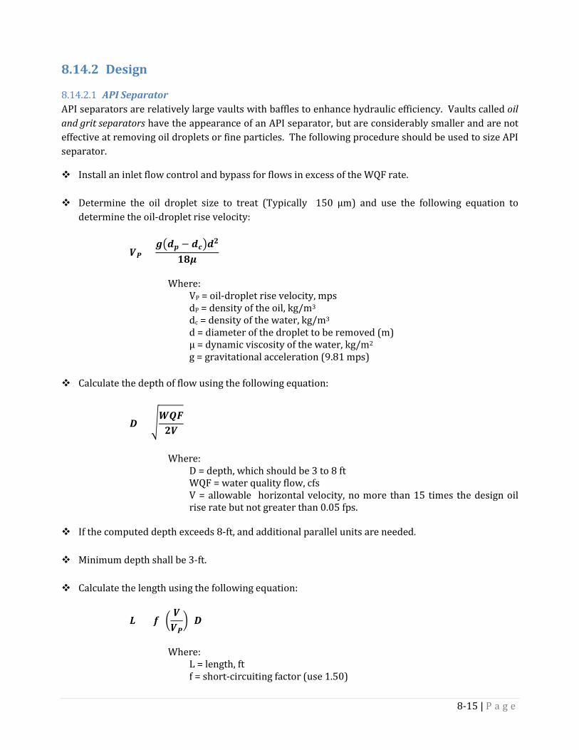
Design 8.14.2
API Separator 8.14.2.1API separators are relatively large vaults with baffles to enhance hydraulic efficiency. Vaults called oil and grit separators have the appearance of an API separator, but are considerably smaller and are not effective at removing oil droplets or fine particles. The following procedure should be used to size API separator.
Install an inlet flow control and bypass for flows in excess of the WQF rate.
Determine the oil droplet size to treat (Typically 150 µm) and use the following equation to determine the oil-droplet rise velocity:
𝑾𝑾𝑷𝑷 =𝒈𝒈�𝒅𝒅𝒑𝒑 − 𝒅𝒅𝒄𝒄�𝒅𝒅𝟏𝟏
𝟏𝟏𝟏𝟏𝟏𝟏
Where:
VP = oil-droplet rise velocity, mps dP = density of the oil, kg/m3
dc = density of the water, kg/m3 d = diameter of the droplet to be removed (m) µ = dynamic viscosity of the water, kg/m2 g = gravitational acceleration (9.81 mps)
Calculate the depth of flow using the following equation:
𝑫𝑫 = �𝑾𝑾𝑾𝑾𝑾𝑾𝟏𝟏𝑾𝑾
Where:
D = depth, which should be 3 to 8 ft WQF = water quality flow, cfs V = allowable horizontal velocity, no more than 15 times the design oil rise rate but not greater than 0.05 fps.
If the computed depth exceeds 8-ft, and additional parallel units are needed.
Minimum depth shall be 3-ft.
Calculate the length using the following equation:
𝑳𝑳 = (𝒇𝒇) �𝑾𝑾𝑾𝑾𝑷𝑷� (𝑫𝑫)
Where:
L = length, ft f = short-circuiting factor (use 1.50)
8-15 | P a g e
V = allowable horizontal velocity, fps VP = oil-droplet rise velocity, fps
The width of the structure should be 2-3 times the depth, but should not exceed 20-ft.
Height to water depth ratios shall be 0.85 for top baffles and 0.15 for bottom baffles.
Locate the distribution baffle at 0.03 gal from the entrance.
Add 1-ft to the depth for freeboard.
Coalescing Plate Separators 8.14.2.2 Where applicable, locate the separator off-line and bypass flows in excess of the water quality
design flow rate;
Follow manufactures standards for coalescing plate oil and water separator.
Access & Maintenance Features 8.14.3 Oil and water separators should be checked after rain and snow melt events and cleaned several
times a year. They should always be cleaned before the start of the wet season, and the oil and other collected materials should be properly disposed.
When vehicle access is necessary, for facilities constructed outside of the street section, access roads shall be provided in dedicated access easements of 20-foot minimum with. The minimum clear driving lane width of access roads is 12 feet. Access roads shall have a maximum grade of nine percent, shall be constructed with gravel, pavement, concrete or an appropriate all-season surface, and shall be accessible to vacuum trucks where appropriate for maintenance.
8.15 MECHANICAL TREATMENT & EMERGING TECHNOLOGY Emerging technologies and mechanical treatments include but are not limited to systems that treat stormwater through filtration, settling, absorption, adsorption, or a combination of these processes. Mechanical treatment using hydrodynamic or swirl action can also be used for sedimentation pretreatment prior to discharging into an approved treatment BMP. The mechanical treatment device shall be approved on a case by case basis. The City of Sheridan will generally allow mechanical treatment systems based on the Washington Department of Ecology’s new technology evaluation program or equivalent. The City Engineer, however reserves the right to deny the use of emerging technologies and mechanical treatment systems even if accepted by the Washington Department of Ecology. The City shall consider the following as they make decisions regarding the use of new stormwater technologies:
An emerging technology shall not be considered for use for new development sites unless there exists a body of supporting data indicating that the performance is expected to be reasonably equivalent to the BMPs already approved by the City.
8-16 | P a g e

When vehicle access is necessary, for facilities constructed outside of the street section, access roads shall be provided in dedicated access easements of 20-foot minimum with. The minimum clear driving lane width of access roads is 12 feet. Access roads shall have a maximum grade of nine percent, shall be constructed with gravel, pavement, concrete or an appropriate all-season surface, and shall be accessible to vacuum trucks where appropriate for maintenance.
8.16 LOW IMPACT DEVELOPMENT The Low impact development (LID) techniques presented below are encouraged for implementation in new residential, commercial and multi-family, and subdivision developments and areas of redevelopment. The primary goal of LID is to mimic the natural site hydrology by using design techniques that store, infiltrate, evapotranspire, and detain runoff at or near the source of runoff. LID manages stormwater in small, cost-effective landscape features located throughout the development instead of through large, costly facilities located at the bottom of the contributing area of runoff. Specific LID controls called Integrated Management Practices (IMPs) can reduce runoff by integrating stormwater controls throughout a site in many small, discrete units. IMPs are distributed in a small portion of each lot, near the source of impacts, virtually eliminating the need for centralized Best Management Practice (BMP) facilities. The following LID techniques and IMPs are encouraged for developments within the City of Sheridan:
Reduce the amount of impervious area Minimize development in natural streams, swales, stream buffers, and floodplains. Minimize disturbance to existing vegetation and soils Depression storage in pervious areas Small Bioretention Basins Dry Wells Filter/Buffer Strips Bio filtration Swales Rain Gardens Cisterns Infiltration Trenches Green Roofs Permeable Pavement Others as approved
8-17 | P a g e
Chapter 9 - Erosion and Sediment Control 9.1 APPLICATION This section provides criteria for selection, design, installation, and maintenance of temporary sediment and erosion control Best Management Practices (BMPs) to reduce impacts from construction activities to surface waters, public rights-of way and adjacent properties.
9.2 SWPPP AND NOI REQUIRED SUBMITTALS A SWPPP (Stormwater Pollution Prevention Plan) and NOI (Notice of Intent) shall be submitted to the Wyoming Department of Environmental Quality (WYDEQ) for approval. The approved SWPPP and NOI shall be submitted to the City prior to any grading on the site.
The WYDEQ, in accordance with federal regulations, requires submittal of a SWPPP and NOI in compliance with the General Permit for public and private projects that:
Disturb one (1) acre or more of land; or
Are part of a larger master plan development or subdivision that will ultimately disturb one (1) acre or more of land
Forms for the SWPPP and NOI can be found at:
http://deq.wyoming.gov/wqd/storm-water-permitting/resources/construction-general-permits/
The General Permit requires the SWPPP and NOI permit holder to:
Be identified within the NOI and match the Owner of the SWPPP. A Certified SWPPP Administrator is required for all construction projects requiring an NOI and SWPPP and shall be identified within the NOI and SWPPP.
Maintain and update the SWPPP to reflect changes on the construction site.
Specify the inspection frequency. Inspections of storm water and erosion controls shall be every 7 days or every 14 days and following each storm event of 0.25" or more.
Maintain inspection records and provide the records upon request by the City and/or WYDEQ.
Maintain and modify temporary BMPs to reflect current conditions of the job site and update site plans and SWPPP language during inspections.
Achieve stabilization and remove all temporary BMPs once 70% of the disturbed area is revegetated.
File a Notice of Termination (NOT) upon stabilization of the site.
9-1 | P a g e
9.3 CONSTRUCTION LESS THAN ONE-ACRE Construction activity disturbing areas less than one acre shall be required to implement BMPs and good housekeeping practices to minimize impacts including, but not limited to, erosion and sediment transport into public right-of-way or onto adjoining property. Homebuilders/contractors are responsible for managing BMPs on individual lots within a subdivision and/or master plan area and are required to follow the requirements in the NOI and SWPPP for the property.
9.4 BEST MANGAGEMENT PRACTICES (BMP) Temporary erosion and sediment control best management practices (BMPs) for construction sites in the City of Sheridan shall be selected, designed, and installed using the methodology presented in the “Construction Site Best Management Practices (BMPs) Manual” by the California Department of Transportation. This reference provides specific guidance on accepted BMPs to reduce erosion and sediment during construction activities and is available as a PDF document through the following link: http://www.dot.ca.gov/hq/construc/stormwater/CSBMPM_303_Final.pdf
Construction details for select Construction Site BMPs are provided in Appendix I. Additional details are available through the following link: http://www.dot.ca.gov/hq/construc/stormwater/details.htm
9.5 CONSTRUCTION ADJACENT TO WATERWAYS In addition to a SWPPP and NOI, if construction activities are planned on or near a waterway in Wyoming, one or several other permits may be required. For the purpose of this manual, a waterway is defined as a ditch, drain, creek, stream, river or wetland. Developer is required to obtain any necessary permit(s) from the appropriate agencies.
9-2 | P a g e
Chapter 10 - Bibliography California Department of Transportation (March, 2003) Storm Water Quality Handbooks, Project
Planning and Design Guide, Storm Water Pollution Prevention Plan (SWPPP) and Water Pollution Control Program (WPCP) Preparation Manual, Construction Site Best Management Practices(BMPs) Manual.
City of Billings, Public Works Department (2015) Stormwater Management Manual), Billings, Montana.
City of Gillette, Department of Engineering (2011) Storm Drainage Design Manual, Gillette, Wyoming.
City of Kalispell, Public Works Department (2009) Standards for Design and Construction, Kalispell, Montana.
City of Sheridan, Public Works Department (2006) Storm Drainage Design Criteria, Sheridan, Wyoming.
City of Poulsbo, Public Works Department (2008) Construction Standards and Specifications, Poulsbo, WA
Georgia Stormwater Management Manual –Volume 1 Stormwater Policy Guidebook. First Edition. August, 2001
Prince George’s County, Maryland, Department of Environmental Resource Programs and Planning Divisions, (June 1999), Low-Impact Development – An Integrated Design Approach
Urban Water Resources Research Council of the American Society of Civil Engineers and the Water Environment Federation (1992) ASCE Manuals and Reports of Engineering Practice No. 77, WEF Manual of Practice FD-20, Design and Construction of Urban Stormwater Management Systems, Library of Congress Catalog No.: 92-36519.
U.S. Department of Transportation, Federal Highway Administration (2006) Hydraulic Engineering Circular No. 14, Hydraulic Design of Energy Dissipaters for Culverts and Channels Publication No. FHWA-NHI-06-086.
U.S. Department of Transportation, Federal Highway Administration (2009) Hydraulic Engineering Circular No. 22, Second Edition, Urban Drainage Design Manual Third Edition, Publication No. FHWA-NHI-10-009, National Highway Institute.
U.S. Department of Transportation, Federal Highway Administration (2012) Hydraulic Design Series Number 5, Hydraulic Design of Highway Culverts Third Edition, Publication No. FHWA-HIF-12-026
Water Environment Federations & American Society of Civil Engineers/Environmental & Water Resource Institute (2012) WEF Manual of Practice No. 23 & ASCE Manuals and Reports of Engineering Practice No. 87, Design of Urban Stormwater Controls
Stormwaterassociation.com, March, 2015.
SWCA Environmental Consultants (September, 2010), Goose Creek Watershed TMDLs Final Report, prepared for Wyoming Department of Environmental Quality
10-1 | P a g e

The Ohio State University. Stormwater Management Program Post Construction BMP Operation and Maintenance Guidance Manual. December 1, 2009.
Wyoming Department of Transportation (1979) Operating Policy 18-6, Drainage Design for Highway Systems, Cheyenne, Wyoming.
10-2 | P a g e
Appendix A Additional Requirements for
Commercial Site Developments
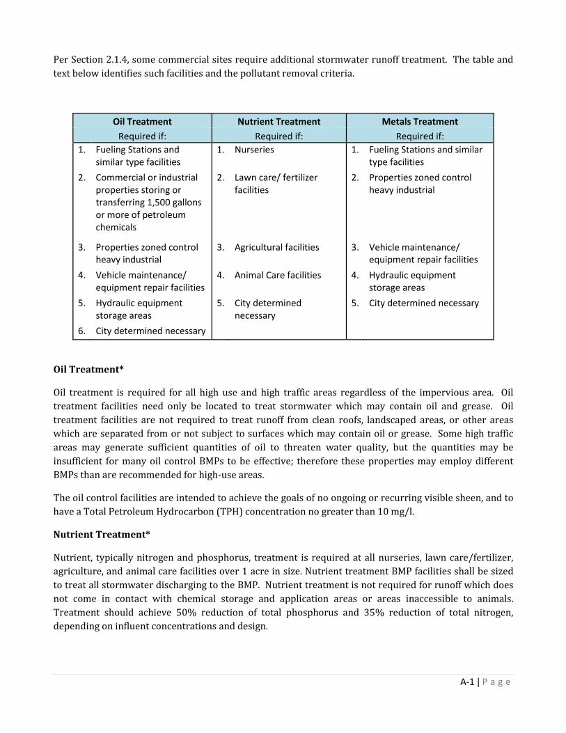
Per Section 2.1.4, some commercial sites require additional stormwater runoff treatment. The table and text below identifies such facilities and the pollutant removal criteria.
Oil Treatment Nutrient Treatment Metals Treatment Required if: Required if: Required if:
1. Fueling Stations and similar type facilities
1. Nurseries 1. Fueling Stations and similar type facilities
2. Commercial or industrial properties storing or transferring 1,500 gallons or more of petroleum chemicals
2. Lawn care/ fertilizer facilities
2. Properties zoned control heavy industrial
3. Properties zoned control heavy industrial
3. Agricultural facilities 3. Vehicle maintenance/ equipment repair facilities
4. Vehicle maintenance/ equipment repair facilities
4. Animal Care facilities 4. Hydraulic equipment storage areas
5. Hydraulic equipment storage areas
5. City determined necessary
5. City determined necessary
6. City determined necessary
Oil Treatment*
Oil treatment is required for all high use and high traffic areas regardless of the impervious area. Oil treatment facilities need only be located to treat stormwater which may contain oil and grease. Oil treatment facilities are not required to treat runoff from clean roofs, landscaped areas, or other areas which are separated from or not subject to surfaces which may contain oil or grease. Some high traffic areas may generate sufficient quantities of oil to threaten water quality, but the quantities may be insufficient for many oil control BMPs to be effective; therefore these properties may employ different BMPs than are recommended for high-use areas.
The oil control facilities are intended to achieve the goals of no ongoing or recurring visible sheen, and to have a Total Petroleum Hydrocarbon (TPH) concentration no greater than 10 mg/l.
Nutrient Treatment*
Nutrient, typically nitrogen and phosphorus, treatment is required at all nurseries, lawn care/fertilizer, agriculture, and animal care facilities over 1 acre in size. Nutrient treatment BMP facilities shall be sized to treat all stormwater discharging to the BMP. Nutrient treatment is not required for runoff which does not come in contact with chemical storage and application areas or areas inaccessible to animals. Treatment should achieve 50% reduction of total phosphorus and 35% reduction of total nitrogen, depending on influent concentrations and design.
A-1 | P a g e
Metals Treatment*
Metals are typically in the form of particles, and are generally removed with basic treatment requirements which remove total suspended solids. Therefore, properties requiring metals treatment should already be treated through TSS treatment. In the event that dissolved metals are reaching water bodies through stormwater runoff, additional control measures, such as filters may be required at such facilities. Metals removal should be from 20 to 85% depending on design, metal state (i.e., dissolved), influent concentration, etc.
*It is the responsibility of the developer to ensure site complies with DEQ, EPA or other agencies which may have regulations not specified in this manual.
A-2 | P a g e
Appendix B Preliminary Drainage Report

The purpose of the preliminary drainage report is to describe and illustrate the preliminary solutions to the drainage problems which may occur on-site and off-site as a result of the development or any phase of the development. The drainage report shall be submitted during the subdivision process with the application for Preliminary Plat.
Preliminary drainage reports shall provide an appropriate level of detail to address drainage issues and present the overall plan for the property. The report shall be based on the following outline and include appropriate background information, supporting data, calculations and plan drawing(s).
TITLE PAGE
1. Type of Report (Concept) 2. Project Name 3. Prepared for/by 4. Date 5. P.E. Seal and Signature
INTRODUCTION
1. Location a. City, County, State Highway and local streets within and adjacent to the site, or the
area to be served by the drainage improvements. b. Names of surrounding developments, properties or landmarks.
2. Description of Property a. Area in acres b. Ground cover (type of ground cover and vegetation) c. Existing land uses and known and foreseeable future land uses d. Topographic features, steepness of slopes e. Major drainage ways and receiving channels f. Existing drainage facilities g. Flood Hazard Zones h. Geologic Features (if applicable) i. Previous drainage studies for the property (if any)
3. Proposed Project Description a. Land uses b. Changes to existing facilities c. Changes to floodplains d. Proposed system improvements
4. Drainage Criteria
a. Minor and Major Storm Analysis b. Geotechnical/Hydrogeological Analysis c. Hydrologic Methods
1. Rainfall 2. Design Storms 3. Runoff methods and computer models
c. Hydraulic Methods 1. Design standards 2. Hydraulic models
B-1 | P a g e
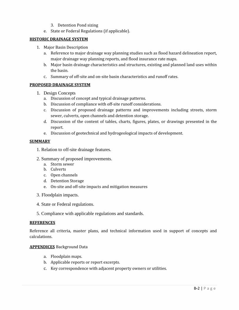
3. Detention Pond sizing e. State or Federal Regulations (if applicable).
HISTORIC DRAINAGE SYSTEM
1. Major Basin Description a. Reference to major drainage way planning studies such as flood hazard delineation report,
major drainage way planning reports, and flood insurance rate maps. b. Major basin drainage characteristics and structures, existing and planned land uses within
the basin. c. Summary of off-site and on-site basin characteristics and runoff rates.
PROPOSED DRAINAGE SYSTEM
1. Design Concepts a. Discussion of concept and typical drainage patterns. b. Discussion of compliance with off-site runoff considerations. c. Discussion of proposed drainage patterns and improvements including streets, storm
sewer, culverts, open channels and detention storage. d. Discussion of the content of tables, charts, figures, plates, or drawings presented in the
report. e. Discussion of geotechnical and hydrogeological impacts of development.
SUMMARY
1. Relation to off-site drainage features.
2. Summary of proposed improvements. a. Storm sewer b. Culverts c. Open channels d. Detention Storage e. On-site and off-site impacts and mitigation measures
3. Floodplain impacts.
4. State or Federal regulations.
5. Compliance with applicable regulations and standards.
REFERENCES
Reference all criteria, master plans, and technical information used in support of concepts and calculations.
APPENDICES Background Data
a. Floodplain maps. b. Applicable reports or report excerpts. c. Key correspondence with adjacent property owners or utilities.
B-2 | P a g e
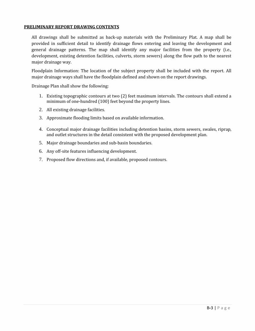
PRELIMINARY REPORT DRAWING CONTENTS
All drawings shall be submitted as back-up materials with the Preliminary Plat. A map shall be provided in sufficient detail to identify drainage flows entering and leaving the development and general drainage patterns. The map shall identify any major facilities from the property (i.e., development, existing detention facilities, culverts, storm sewers) along the flow path to the nearest major drainage way.
Floodplain Information: The location of the subject property shall be included with the report. All major drainage ways shall have the floodplain defined and shown on the report drawings.
Drainage Plan shall show the following:
1. Existing topographic contours at two (2) feet maximum intervals. The contours shall extend a minimum of one-hundred (100) feet beyond the property lines.
2. All existing drainage facilities.
3. Approximate flooding limits based on available information.
4. Conceptual major drainage facilities including detention basins, storm sewers, swales, riprap, and outlet structures in the detail consistent with the proposed development plan.
5. Major drainage boundaries and sub-basin boundaries.
6. Any off-site features influencing development.
7. Proposed flow directions and, if available, proposed contours.
B-3 | P a g e
Appendix C Final Drainage Report

The purpose of the Final Drainage Report is to present the final design details for the drainage facilities discussed in the Preliminary Drainage Plan. Any changes to the preliminary concept must be presented and fully explained.
Drainage plan shall provide an appropriate level of detail to address the drainage issues and present sizing and locations for all proposed improvements. The report shall be based on the following outline and include appropriate background information and supporting data and calculations and plan drawing(s).
TITLE PAGE
1. Type of Report (Final) 2. Project Name 3. Prepared for/by 4. Date
CERTIFICATION PAGE (found in Appendix G)
1. Project Name 2. P.E., P.G., P.H. Seal and Signature
INTRODUCTION
1. Location a. City, County, State Highway and local streets within and adjacent to the site, or
the area to be served by the drainage improvements. b. Names of surrounding developments, properties or landmarks.
2. Description of Property a. Area in acres b. Ground cover (type of ground cover and vegetation) c. Existing land uses and known and foreseeable future land uses d. Topographic features, steepness of slopes e. Major drainage ways and receiving channels f. Existing drainage facilities g. Flood Hazard Zones h. Geologic Features (if applicable)
3. Previous drainage studies for the property (if any) a. Proposed Project Description a. Land uses b. Changes to existing facilities c. Changes to floodplains d. Proposed system improvements e. Right-of-way conveyance or acquisition required
4. Drainage Criteria a. Application Standards or exceptions b. Minor and Major Storm Frequencies c. Hydrologic Methods
1. Rainfall
C-1 | P a g e

2. Design Storms 3. Runoff methods and computer models 4. Geotechnical/Hydrogeological Analysis (Attach Reports)
d. Hydraulic Methods 1. Design standards 2. Hydraulic models 3. Detention Pond sizing
a. State or Federal Regulations (if applicable).
HISTORIC DRAINAGE SYSTEM
1. Major Basin Description a. Reference to major drainage way planning studies such as flood hazard
delineation report, major drainage way planning reports, and flood insurance rate maps.
b. Major basin drainage characteristics and structures, existing and planned land uses within the basin.
c. Summary of off-site and on-site basin characteristics and runoff rates. 2. Sub-Basin Description
a. Discussions of historic drainage patterns of the property. b. Discussion of off-site drainage flows and flow patterns and impact on
development under existing and fully developed basin conditions. c. Summary of off-site and on-site basin characteristics and runoff rates.
PROPOSED DRAINAGE SYSTEM
1. Design Concepts a. Discussion of minor and major drainage patterns, impacts, flows, volumes and
patterns. b. Discussion of compliance with off-site runoff considerations. c. Discussion of proposed drainage patterns and improvements including streets,
storm sewer, culverts, open channels and detention storage. d. Discussion of the tables, charts, figures, plates, or drawings presented in the
report. 2. Design Details
a. Discussion of drainage problems encountered and solutions at specific design points.
b. Discussion of detention storage and outlet design. c. Discussion of maintenance and access aspects of the design. d. Discussion of impacts of concentrating the flow on the downstream properties. e. Summary of basin characteristics and runoff rates. f. Discussion of geotechnical and hydrogeological impacts of development. g. Discuss flooding hazards and describe minimum building elevations.
C-2 | P a g e

SUMMARY
1. Relation to off-site drainage features. 2. Summary of proposed improvements.
a. Storm sewer b. Culverts c. Open channels d. Detention Storage e. Geotechnical/Hydrologic impacts f. On-site and off-site impacts and mitigation measures
3. Floodplain impacts. 4. State or Federal regulations. 5. Compliance with applicable regulations and standards.
REFERENCES
Reference all criteria, master plans, and technical information used in support of concepts and calculations.
APPENDICES
1. Background Data a. Floodplain maps. b. Applicable reports or report excerpts. c. Key correspondence with adjacent property owners or utilities.
2. Hydrologic Computations
a. Land uses regarding adjacent properties. b. Soil types, coverage and loss coefficients c. Proposed land uses for project by basin. d. Time of concentration and runoff coefficients for each basin. e. Basin parameters used for modeling including basin area, length, slope, distance
to centroid and routing elements. f. Initial and major storm runoff at specific design points for off-site and on-site
flows. g. Off-site, historic and fully developed runoff computations at specific design
points h. Hydrographs at critical design points. i. Schematic diagram of hydrology model showing basins and routing elements
and combination elements.
3. Hydraulic Computations a. Culvert Capacities and inlet and outlet protection. b. Storm sewer capacity, including energy grade line (EGL) and hydraulic grade
line (HGL) elevations. c. Gutter capacity as compared to allowable. d. Storm inlet capacity including roughness coefficients, trickle channels,
freeboard, hydraulic grade line, and slope protection.
C-3 | P a g e

e. Check and/or channel drop placement. f. Detention area volume capacity and outlet capacity calculations; depths of
detention basins, outlet configuration. g. Downstream/outfall capacity to the Major Drainage way system.
4. Miscellaneous Information
a. Other documents relating to drainage conditions on the property. b. Agreements with property owners or other agencies. c. Permits, etc.
C-4 | P a g e

Appendix D Geotechnical/Hydrogeological Report
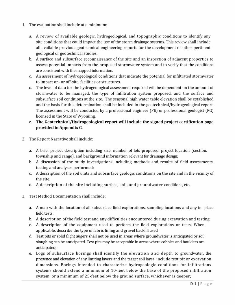
1. The evaluation shall include at a minimum: a. A review of available geologic, hydrogeological, and topographic conditions to identify any
site conditions that could impact the use of the storm drainage systems. This review shall include all available previous geotechnical engineering reports for the development or other pertinent geological or geotechnical studies.
b. A surface and subsurface reconnaissance of the site and an inspection of adjacent properties to assess potential impacts from the proposed stormwater system and to verify that the conditions are consistent with the mapped information.
c. An assessment of hydrogeological conditions that indicate the potential for infiltrated stormwater to impact on- or off-site, facilities or structures.
d. The level of data for the hydrogeological assessment required will be dependent on the amount of stormwater to be managed, the type of infiltration system proposed, and the surface and subsurface soil conditions at the site. The seasonal high water table elevation shall be established and the basis for this determination shall be included in the geotechnical/hydrogeological report. The assessment will be conducted by a professional engineer (PE) or professional geologist (PG) licensed in the State of Wyoming.
e. The Geotechnical/Hydrogeological report will include the signed project certification page provided in Appendix G.
2. The Report Narrative shall include: a. A brief project description including size, number of lots proposed, project location (section,
township and range), and background information relevant for drainage design; b. A discussion of the study investigations including methods and results of field assessments,
testing and analyses performed; c. A description of the soil units and subsurface geologic conditions on the site and in the vicinity of
the site; d. A description of the site including surface, soil, and groundwater conditions, etc.
3. Test Method Documentation shall include:
a. A map with the location of all subsurface field explorations, sampling locations and any in- place
field tests; b. A description of the field test and any difficulties encountered during excavation and testing; c. A description of the equipment used to perform the field explorations or tests. When
applicable, describe the type of fabric lining and gravel backfill used d. Test pits or solid flight augers shall not be used in areas where groundwater is anticipated or soil
sloughing can be anticipated. Test pits may be acceptable in areas where cobbles and boulders are anticipated;
e. Logs of subsurface borings shall identify the elevation and depth to groundwater, the presence and elevation of any limiting layers and the target soil layer; include test pit or excavation dimensions. Borings intended to characterize hydrogeologic conditions for infiltrations systems should extend a minimum of 10-feet below the base of the proposed infiltration system, or a minimum of 25-feet below the ground surface, whichever is deeper;
D-1 | P a g e
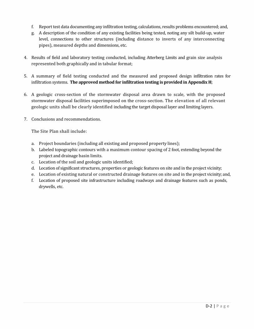
f. Report test data documenting any infiltration testing, calculations, results problems encountered; and, g. A description of the condition of any existing facilities being tested, noting any silt build-up, water
level, connections to other structures (including distance to inverts of any interconnecting pipes), measured depths and dimensions, etc.
4. Results of field and laboratory testing conducted, including Atterberg Limits and grain size analysis represented both graphically and in tabular format;
5. A summary of field testing conducted and the measured and proposed design infiltration rates for infiltration systems. The approved method for infiltration testing is provided in Appendix H;
6. A geologic cross-section of the stormwater disposal area drawn to scale, with the proposed
stormwater disposal facilities superimposed on the cross-section. The elevation of all relevant geologic units shall be clearly identified including the target disposal layer and limiting layers.
7. Conclusions and recommendations.
The Site Plan shall include:
a. Project boundaries (including all existing and proposed property lines); b. Labeled topographic contours with a maximum contour spacing of 2 foot, extending beyond the
project and drainage basin limits. c. Location of the soil and geologic units identified; d. Location of significant structures, properties or geologic features on site and in the project vicinity; e. Location of existing natural or constructed drainage features on site and in the project vicinity; and, f. Location of proposed site infrastructure including roadways and drainage features such as ponds,
drywells, etc.
D-2 | P a g e
Appendix E Operations and Maintenance
Requirements
OPERATION AND MAINTENANCE
For stormwater systems operated and maintained by a HOA, or any facilities to be owned and maintained by the City of Sheridan, an O&M Manual is required. Some commercial sites may also be required to submit an O&M Manual if it is deemed that failure of the commercial property to maintain their facility will have a negative impact on the City of Sheridan storm drain system. The O&M Manual summarizes the tasks required for perpetual maintenance to ensure the proper operation of stormwater facilities. The O&M manual shall include at a minimum:
• Contact information for the party responsible for O&M.
• Description of the operation and maintenance tasks to be performed and their frequency.
• An inspection checklist to be used for annual maintenance. Template forms found in Appendix G.
• List of the expected design life and replacement schedule of each component.
• Site plan showing the overall layout of the development.
• Copy of recorded HOA Agreement and Development Agreement, if applicable.
• Other information as necessary.
E-1 | P a g e
Appendix F HOA Agreement Requirements

HOMEOWNERS’ ASSOCIATIONS REQUIREMENTS
For privately maintained stormwater systems in residential neighborhoods, a homeowner’s association shall be formed to maintain and operate the facilities located outside of the public right of way.
A draft copy of the HOA agreement shall be submitted at the time of Preliminary Plat submittal. Final copies are required at the time of Final Plat submittal. The Development Agreement shall summarize the maintenance and fiscal responsibilities of the HOA. The O&M manual shall also be submitted at this time. A financial plan is required in order to provide the entity responsible for maintenance with guidance in regard to financial planning for maintenance and replacement costs. The financial plan shall include the following items:
• A list of all stormwater-related facilities and their expected date of replacement and associated
replacement costs.
• Sinking fund calculations that take into consideration probable inflation over the life of the infrastructure and estimates the funds that need to be set aside annually.
• A mechanism for initiating and sustaining the sinking fund account demonstrating that perpetual
maintenance of all facilities associated with the stormwater system will be sustained. Homeowners’ associations are to be non-profit organizations. A standard business license is not acceptable for this purpose. The HOA shall remain in good standing with the requirements of the State of Wyoming. Developer shall sign HOA Agreement stating ownership and responsibilities prior to approval of development. A template agreement is found in Appendix G.
F-1 | P a g e

Appendix G Template Forms
• HOA MAINTENANCE AGREEMENT • BMP INSPECTION FORM • REPORT CERTIFICATION FORM
HOA MAINTENACE AGREEMENT
G-1 | P a g e

HOA Stormwater Facility Maintenance Agreement
THIS Agreement is made by and between the City of Sheridan, a municipal corporation of the State of Wyoming, hereinafter
referred to as the “City” and ____________________________________, a Developer, as owner (including successors and assignee’s of the City as may become applicable including the heirs, executors, administrators, successors and assigns of above owner(s) as may be or may become applicable), hereinafter called “Grantor,” (if more than one grantor is listed above, said language herein referring thereto shall be interpreted in the plural and refer jointly and severally to such grantors).
WHEREAS, the undersigned is proceeding to build on and develop the property; and has submitted the Site Plan/Subdivision Plan know as ___________________________________________ (Name of Plan/Development) hereinafter called the "Plan", which is expressly made a part hereof, as approved or to be approved by the City, provides for detention of stormwater within the confines of the property; and
WHEREAS, the City and the undersigned, its successors and assigns, including any homeowners association, (hereinafter the “Landowner”) agree that the health, safety, and welfare of the residents of the City, requires that on-site stormwater management facilities be constructed and maintained on the Property; and
WHEREAS, the City requires that on-site stormwater management facilities as shown on the Plan (the “Facilities”) be constructed and adequately maintained by the Landowner.
NOW, THEREFORE, in consideration of the foregoing premises, the mutual covenants contained herein, and the following terms and conditions, the parties hereto agree as follows: 1. The Facilities shall be constructed by the Landowner, in accordance with the plans and specifications identified in the Plan. 2. The Landowner shall at all time, adequately maintain the Facilities. Such maintenance obligation shall include the obligation to properly maintain all surface and subsurface inlets, pipes, channels, structures, rock pits, vegetation, and all other improvements provided to control the quantity and quality of the stormwater within the facility. Adequate maintenance is herein defined as keeping the Facilities and all components thereof in good working condition so that these Facilities continue to perform their design functions. 3. In the event the Landowner fails to maintain the Facilities in good working condition acceptable to the City, the City may enter upon the Property and take such steps as are necessary to correct deficiencies identified in the inspection report and to charge the costs of such repairs to the Landowner. This provision shall not be construed to allow the City to erect any structure of permanent nature on the land of the Developer outside of the easement for the stormwater management facilities. It is expressly understood and agreed that the City is under no obligation to routinely maintain or repair said facilities, and in no event shall this Agreement be construed to impose any such obligation on the City. The Landowner grants to the City, its authorized agents and employees, a non-exclusive, perpetual easement over, across, under and through the Property for such purposes. 4. The Landowner shall perform all work necessary to keep the Facilities in good working order. In the event a maintenance schedule for the stormwater management facilities (including sediment removal) is outlined on the approved plans, the Landowner shall comply with such schedule. 5. In the event the City performs work of any nature on the Facilities in accordance with this Agreement, or expends any funds in performance of said work for labor, use of equipment, supplies, materials, and the like, the Landowner shall reimburse the City upon demand, within thirty (30) days of receipt thereof for all actual costs incurred by the City hereunder. 6. This Agreement imposes no liability of any kind whatsoever on the City and the Landowner agrees to hold the City harmless from any liability in the event the stormwater management facilities fail to operate properly. 7. This Agreement shall be recorded among the deed records of Sheridan County, Wyoming and shall constitute a covenant running with the land, and shall be binding on the Landowner, its administrators, executors, assigns, heirs and any other successors in interests, including any homeowners association.
G-2 | P a g e
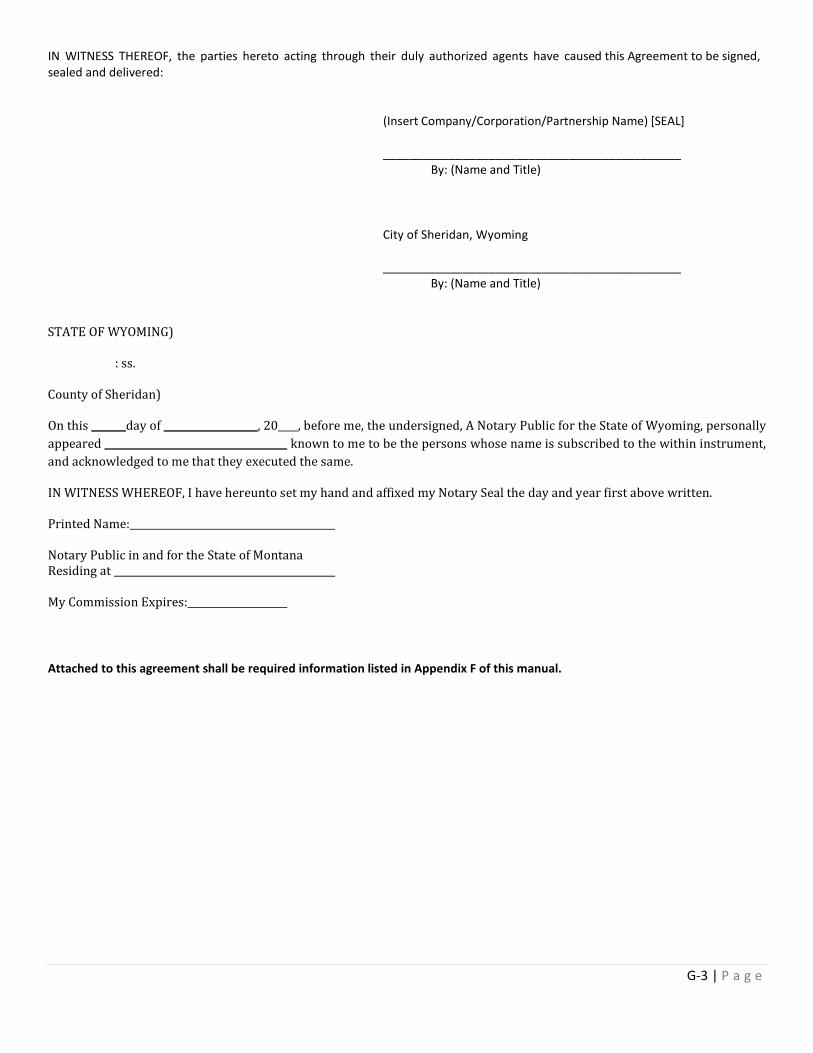
IN WITNESS THEREOF, the parties hereto acting through their duly authorized agents have caused this Agreement to be signed, sealed and delivered:
(Insert Company/Corporation/Partnership Name) [SEAL] _____________________________________________ By: (Name and Title)
City of Sheridan, Wyoming _____________________________________________ By: (Name and Title) STATE OF WYOMING)
: ss.
County of Sheridan)
On this _______day of ___________________, 20____, before me, the undersigned, A Notary Public for the State of Wyoming, personally appeared _____________________________________ known to me to be the persons whose name is subscribed to the within instrument, and acknowledged to me that they executed the same.
IN WITNESS WHEREOF, I have hereunto set my hand and affixed my Notary Seal the day and year first above written.
Printed Name:
Notary Public in and for the State of Montana Residing at
My Commission Expires:
Attached to this agreement shall be required information listed in Appendix F of this manual.
G-3 | P a g e

POST CONSTRUCTION BMP INSPECTION CHECKLIST
G-4 | P a g e
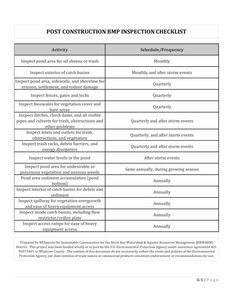
POST CONSTRUCTION BMP INSPECTION CHECKLIST
Monthly
Schedule/Frequency
Annually
Annually
Inspect pond area, sidewalls, and shoreline for erosion, settlement, and rodent damage
Inspect exterior of catch basins
Annually
Annually
Annually
Quarterly
Monthly and after storm events
Quarterly and after storm events
Quarterly, and after storm events
Quarterly and after storm events
Quarterly
Inspect ditches, check dams, and all visible pipes and culverts for trash, obstructions and
other problems
Inspect bioswales for vegetation cover and bare areas
Inspect fences, gates and locks
Quarterly
Prepared by RESources for Sustainable Communities for the Birch Bay Watershed & Aquatic Resources Management (BBWARM) District. This project was been funded wholly or in part by the U.S. Environmental Protection Agency under assistance agreement WS-
96073401 to Whatcom County. The content of this document do not necessarily reflect the views and policies of the Environmental Protection Agency, nor does mention of trade names or commercial products constitute endorsement or recommendations for use.
Inspect pond area for oil sheens or trash
Inspect access ramps for ease of heavy equipment access
Inspect inside catch basins, including flow restrictor/orifice plate
Inspect spillway for vegetation overgrowth and ease of heavy equipment access
Inspect interior of catch basins for debris and sediment
Pond area sediment accumulation (pond bottom)
Inspect pond area for undesirable or poisonous vegetation and noxious weeds
Inspect water levels in the pond
Inspect trash racks, debris barriers, and energy dissipaters
Inspect inlets and outlets for trash, obstructions, and vegetation
Activity
Semi-annually, during growing season
After storm events
G-5 | P a g e
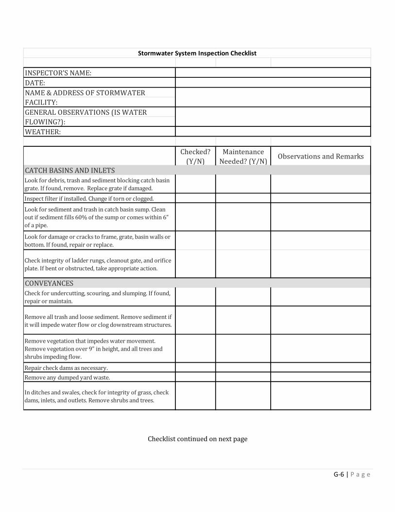
Checklist continued on next page
INSPECTOR’S NAME:DATE:NAME & ADDRESS OF STORMWATERFACILITY:GENERAL OBSERVATIONS (IS WATERFLOWING?):WEATHER:
Checked? (Y/N)
Maintenance Needed? (Y/N) Observations and Remarks
Look for debris, trash and sediment blocking catch basin grate. If found, remove. Replace grate if damaged.Inspect filter if installed. Change if torn or clogged.
Look for sediment and trash in catch basin sump. Clean out if sediment fills 60% of the sump or comes within 6” of a pipe.
Look for damage or cracks to frame, grate, basin walls or bottom. If found, repair or replace.
Check integrity of ladder rungs, cleanout gate, and orifice plate. If bent or obstructed, take appropriate action.
Check for undercutting, scouring, and slumping. If found, repair or maintain.
Remove all trash and loose sediment. Remove sediment if it will impede water flow or clog downstream structures.
Remove vegetation that impedes water movement. Remove vegetation over 9” in height, and all trees and shrubs impeding flow.
Repair check dams as necessary.Remove any dumped yard waste.
In ditches and swales, check for integrity of grass, check dams, inlets, and outlets. Remove shrubs and trees.
CATCH BASINS AND INLETS
CONVEYANCES
Stormwater System Inspection Checklist
G-6 | P a g e
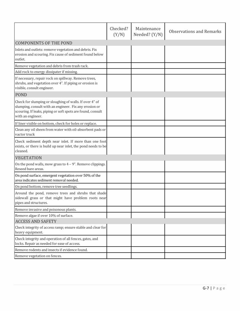
Checked? (Y/N)
Maintenance Needed? (Y/N) Observations and Remarks
Inlets and outlets: remove vegetation and debris. Fix erosion and scouring. Fix cause of sediment found below outlet.
Remove vegetation and debris from trash rack.Add rock to energy dissipater if missing.
If necessary, repair rock on spillway. Remove trees, shrubs, and vegetation over 4”. If piping or erosion is visible, consult engineer.
Check for slumping or sloughing of walls. If over 4” of slumping, consult with an engineer. Fix any erosion or scouring. If leaks, piping or soft spots are found, consult with an engineer.
If liner visible on bottom, check for holes or replace.Clean any oil sheen from water with oil-absorbent pads or vactor truck
Check sediment depth near inlet. If more than one footexists, or there is build up near inlet, the pond needs to becleaned.
On the pond walls, mow grass to 4 – 9”. Remove clippings. Reseed bare areas.
On pond surface, emergent vegetation over 50% of the area indicates sediment removal needed.On pond bottom, remove tree seedlings.
Around the pond, remove trees and shrubs that shadesidewall grass or that might have problem roots nearpipes and structures.
Remove invasive and poisonous plants.Remove algae if over 10% of surface.
Check integrity of access ramp; ensure stable and clear for heavy equipment.
Check integrity and operation of all fences, gates, and locks. Repair as needed for ease of access.Remove rodents and insects if evidence found.Remove vegetation on fences.
POND
COMPONENTS OF THE POND
ACCESS AND SAFETY
VEGETATION
G-7 | P a g e
REPORT/CONSTRUCTION PLANS CERTIFICATION FORM
G-8 | P a g e
(Project Title)
FINAL DRAINAGE, GEOTECHNICAL OR HYDROGEOLOGICAL REPORT
-OR-
FINAL OR AS-BUILT CONSTRUCTION PLAN
(List one from the above categories)
(LOCATION)
CERTIFICATION
I hereby state that this [Final Drainage, Geotechnical or Hydrogeological Report –OR- Final or As-Built Construction Plan] (pick one) has been prepared by me or under my supervision and meets the standard of care and expertise which is usual and customary in this community of professional engineers and geologists (pick one). The analysis has been prepared utilizing procedures and practices specified by the City of Sheridan and within the standard accepted practices.
PE or PG STAMP OR SEAL
____________________________________ __________________________
John Doe, P.E. or P.G. Date
G-9 | P a g e
Appendix H Soil Infiltration
Testing Requirement
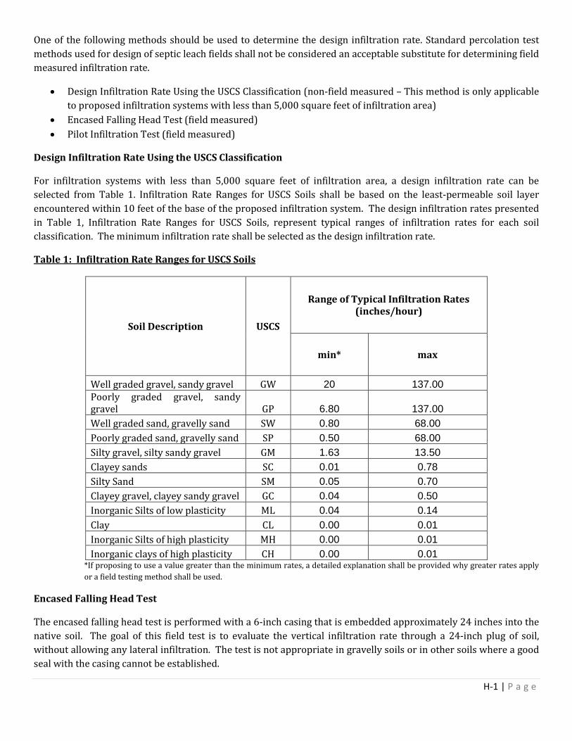
One of the following methods should be used to determine the design infiltration rate. Standard percolation test methods used for design of septic leach fields shall not be considered an acceptable substitute for determining field measured infiltration rate.
• Design Infiltration Rate Using the USCS Classification (non-field measured – This method is only applicable to proposed infiltration systems with less than 5,000 square feet of infiltration area)
• Encased Falling Head Test (field measured) • Pilot Infiltration Test (field measured)
Design Infiltration Rate Using the USCS Classification
For infiltration systems with less than 5,000 square feet of infiltration area, a design infiltration rate can be selected from Table 1. Infiltration Rate Ranges for USCS Soils shall be based on the least-permeable soil layer encountered within 10 feet of the base of the proposed infiltration system. The design infiltration rates presented in Table 1, Infiltration Rate Ranges for USCS Soils, represent typical ranges of infiltration rates for each soil classification. The minimum infiltration rate shall be selected as the design infiltration rate.
Table 1: Infiltration Rate Ranges for USCS Soils
Soil Description USCS
Range of Typical Infiltration Rates (inches/hour)
min* max
Well graded gravel, sandy gravel GW 20 137.00 Poorly graded gravel, sandy gravel GP 6.80 137.00 Well graded sand, gravelly sand SW 0.80 68.00 Poorly graded sand, gravelly sand SP 0.50 68.00 Silty gravel, silty sandy gravel GM 1.63 13.50 Clayey sands SC 0.01 0.78 Silty Sand SM 0.05 0.70 Clayey gravel, clayey sandy gravel GC 0.04 0.50 Inorganic Silts of low plasticity ML 0.04 0.14 Clay CL 0.00 0.01 Inorganic Silts of high plasticity MH 0.00 0.01 Inorganic clays of high plasticity CH 0.00 0.01
*If proposing to use a value greater than the minimum rates, a detailed explanation shall be provided why greater rates apply or a field testing method shall be used.
Encased Falling Head Test
The encased falling head test is performed with a 6-inch casing that is embedded approximately 24 inches into the native soil. The goal of this field test is to evaluate the vertical infiltration rate through a 24-inch plug of soil, without allowing any lateral infiltration. The test is not appropriate in gravelly soils or in other soils where a good seal with the casing cannot be established.
H-1 | P a g e
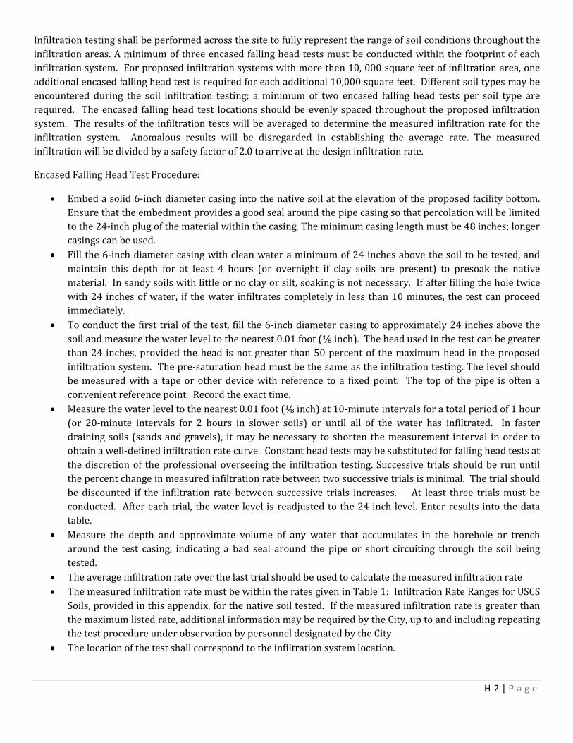
Infiltration testing shall be performed across the site to fully represent the range of soil conditions throughout the infiltration areas. A minimum of three encased falling head tests must be conducted within the footprint of each infiltration system. For proposed infiltration systems with more then 10, 000 square feet of infiltration area, one additional encased falling head test is required for each additional 10,000 square feet. Different soil types may be encountered during the soil infiltration testing; a minimum of two encased falling head tests per soil type are required. The encased falling head test locations should be evenly spaced throughout the proposed infiltration system. The results of the infiltration tests will be averaged to determine the measured infiltration rate for the infiltration system. Anomalous results will be disregarded in establishing the average rate. The measured infiltration will be divided by a safety factor of 2.0 to arrive at the design infiltration rate.
Encased Falling Head Test Procedure:
• Embed a solid 6-inch diameter casing into the native soil at the elevation of the proposed facility bottom. Ensure that the embedment provides a good seal around the pipe casing so that percolation will be limited to the 24-inch plug of the material within the casing. The minimum casing length must be 48 inches; longer casings can be used.
• Fill the 6-inch diameter casing with clean water a minimum of 24 inches above the soil to be tested, and maintain this depth for at least 4 hours (or overnight if clay soils are present) to presoak the native material. In sandy soils with little or no clay or silt, soaking is not necessary. If after filling the hole twice with 24 inches of water, if the water infiltrates completely in less than 10 minutes, the test can proceed immediately.
• To conduct the first trial of the test, fill the 6-inch diameter casing to approximately 24 inches above the soil and measure the water level to the nearest 0.01 foot (⅛ inch). The head used in the test can be greater than 24 inches, provided the head is not greater than 50 percent of the maximum head in the proposed infiltration system. The pre-saturation head must be the same as the infiltration testing. The level should be measured with a tape or other device with reference to a fixed point. The top of the pipe is often a convenient reference point. Record the exact time.
• Measure the water level to the nearest 0.01 foot (⅛ inch) at 10-minute intervals for a total period of 1 hour (or 20-minute intervals for 2 hours in slower soils) or until all of the water has infiltrated. In faster draining soils (sands and gravels), it may be necessary to shorten the measurement interval in order to obtain a well-defined infiltration rate curve. Constant head tests may be substituted for falling head tests at the discretion of the professional overseeing the infiltration testing. Successive trials should be run until the percent change in measured infiltration rate between two successive trials is minimal. The trial should be discounted if the infiltration rate between successive trials increases. At least three trials must be conducted. After each trial, the water level is readjusted to the 24 inch level. Enter results into the data table.
• Measure the depth and approximate volume of any water that accumulates in the borehole or trench around the test casing, indicating a bad seal around the pipe or short circuiting through the soil being tested.
• The average infiltration rate over the last trial should be used to calculate the measured infiltration rate • The measured infiltration rate must be within the rates given in Table 1: Infiltration Rate Ranges for USCS
Soils, provided in this appendix, for the native soil tested. If the measured infiltration rate is greater than the maximum listed rate, additional information may be required by the City, up to and including repeating the test procedure under observation by personnel designated by the City
• The location of the test shall correspond to the infiltration system location.
H-2 | P a g e
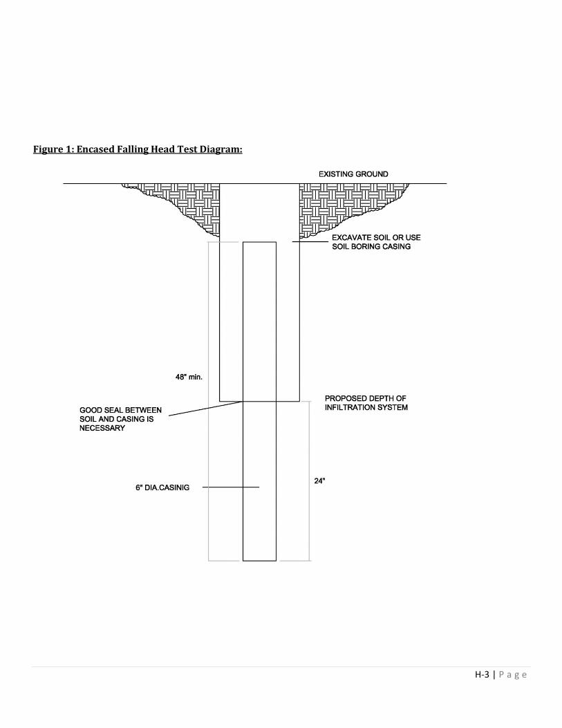
Figure 1: Encased Falling Head Test Diagram:
H-3 | P a g e
Pilot Infiltration Test
Large-scale infiltration testing using the Pilot Infiltration Test described below is the preferred method for estimating the measured infiltration rate of the soil profile beneath proposed infiltration systems. The Pilot Infiltration Test is not a standard test but rather a practical field procedure recommended by the City of Sheridan.
A minimum number of two pilot infiltration tests must be conducted within the footprint of each proposed infiltration system. For proposed infiltration systems with more then 10, 000 square feet of infiltration area, one additional pilot infiltration test is required for each additional 10,000 SF. The pilot infiltration test locations should be evenly spaced throughout the proposed infiltration system. The results of the infiltration tests will be averaged to determine the measured infiltration rate for the infiltration system. The pilot infiltration test will produce a measured infiltration rate in inches per hour. The measured infiltration will be divided by a factor of safety of 2.0 to arrive at the design infiltration rate.
Pilot Infiltration Test Procedure:
• Excavate the test pit to the estimated surface elevation of the proposed infiltration system. Lay back the slopes sufficiently to avoid caving and erosion during the test. Alternatively, consider shoring the sides of the test pit.
• The horizontal surface area of the bottom of the test pit should be approximately 100 square feet. Accurately document the size and geometry of the test pit.
• Install a vertical measuring rod (minimum 5-ft. long) marked in 1/8” increments in the center of the pit bottom
• Use a rigid pipe with a splash plate on the bottom to convey water to the pit and reduce side-wall erosion or excessive disturbance of the pond bottom. Excessive erosion and bottom disturbance will result in clogging of the infiltration receptor and yield lower than actual infiltration rates.
• Add water to the pit at a rate that will maintain a water level between 6 and 12 inches above the bottom of the pit. A rotameter can be used to measure the flow rate into the pit. Every 15-30 min, record the cumulative volume and instantaneous flow rate in gallons per minute necessary to maintain the water level at the same point on the measuring rod. Keep adding water to the pit until one hour after the flow rate into the pit has stabilized (constant flow rate; a goal of 5% variation or less variation in the total flow) while maintaining the same pond water level. The total of the pre-soak time plus one hour after the flow rate has stabilized should be no less than 6 hours.
• After the flow rate has stabilized for at least one hour, turn off the water and record the rate of infiltration (the drop rate of the standing water) in inches per hour from the measuring rod data, until the water has infiltrated completely. Calculate and record the measured infiltration rate in inches per hour in 30 minutes or one-hour increments.
• The measured infiltration rate must be within the ranges given in Table 1: Infiltration Rate Ranges for USCS Soils, provided in this appendix, for the native soil tested. If the measured infiltration rate is greater than the maximum listed rate, additional information may be required by the City, up to and including repeating the test procedure under observation by personnel designated by the City.
• The location of the test shall correspond to the infiltration system location.
H-4 | P a g e
Appendix I Erosion and Sediment Control BMPs
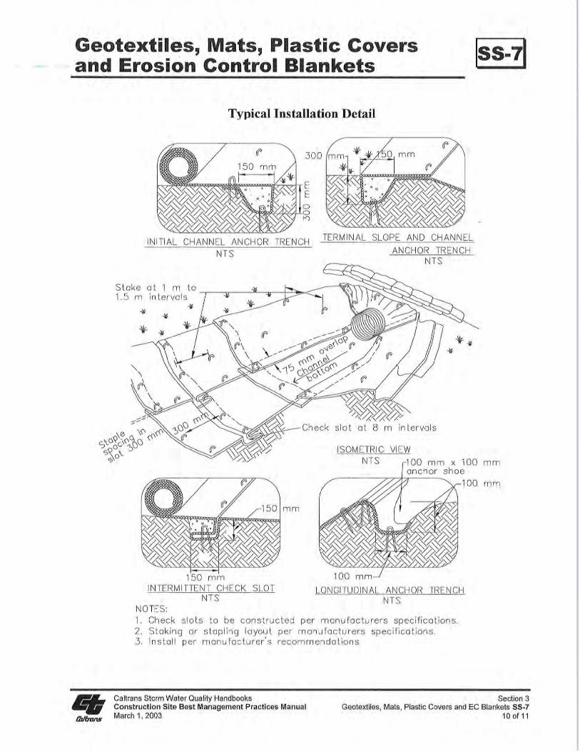
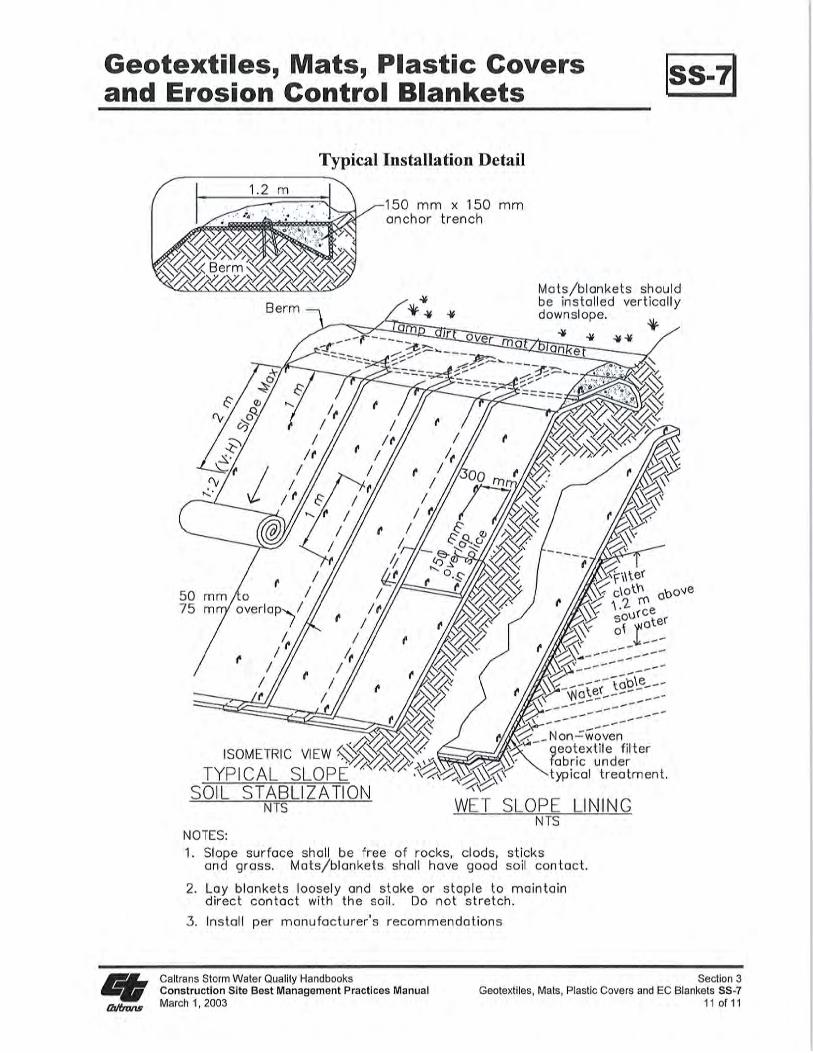
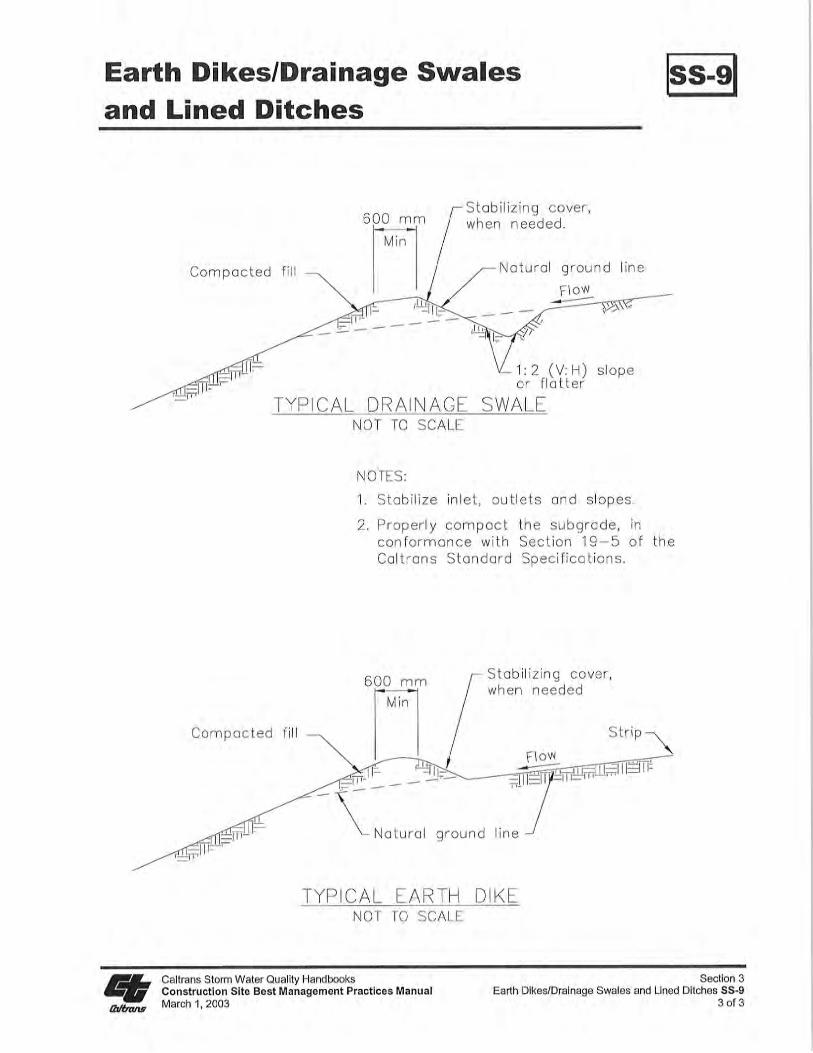
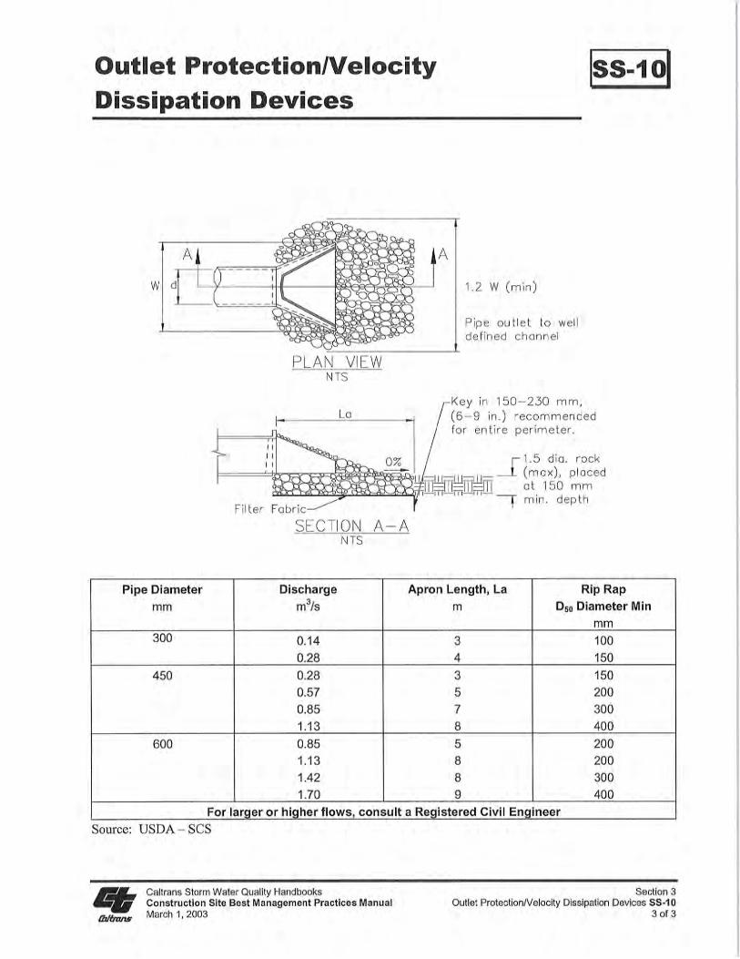
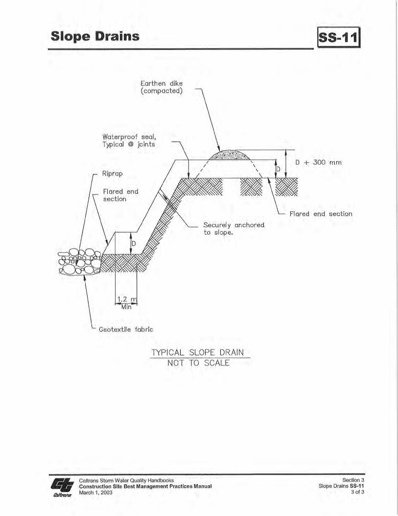
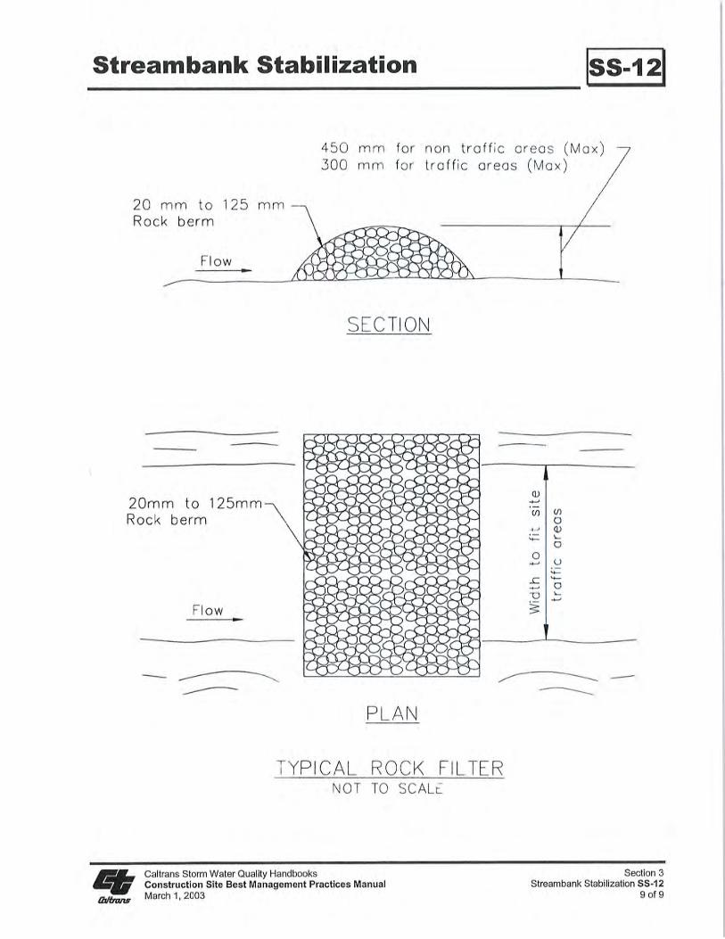
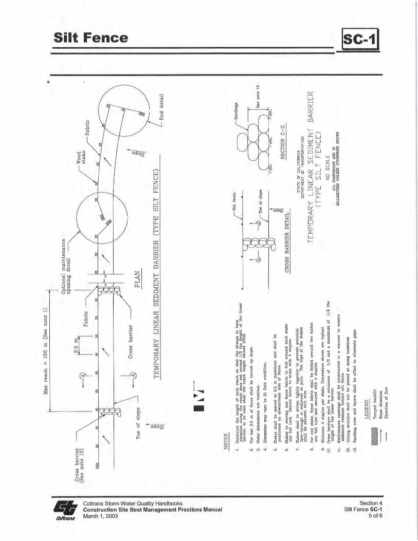
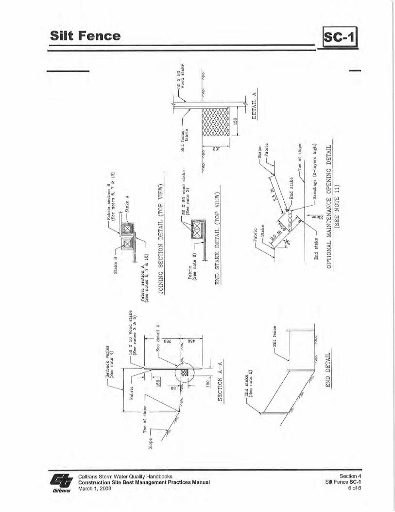
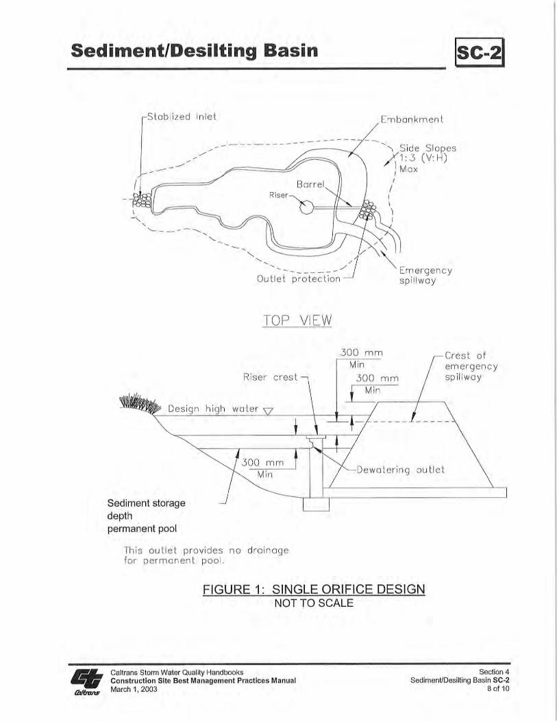
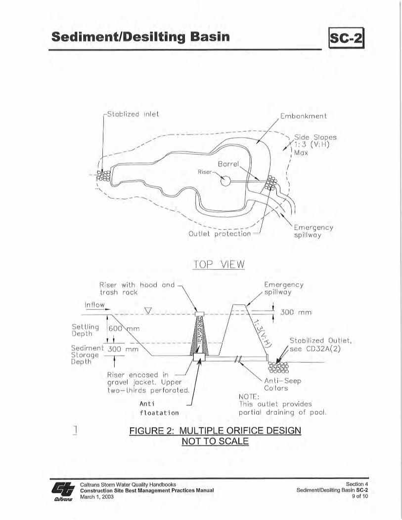
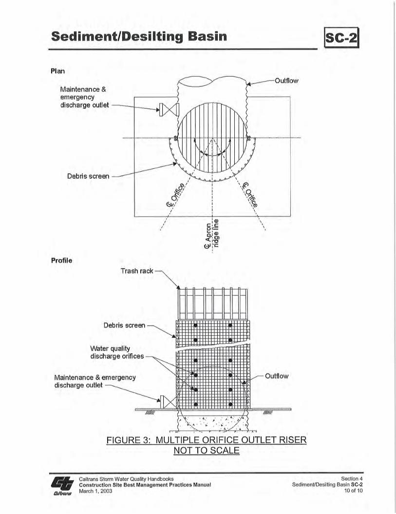

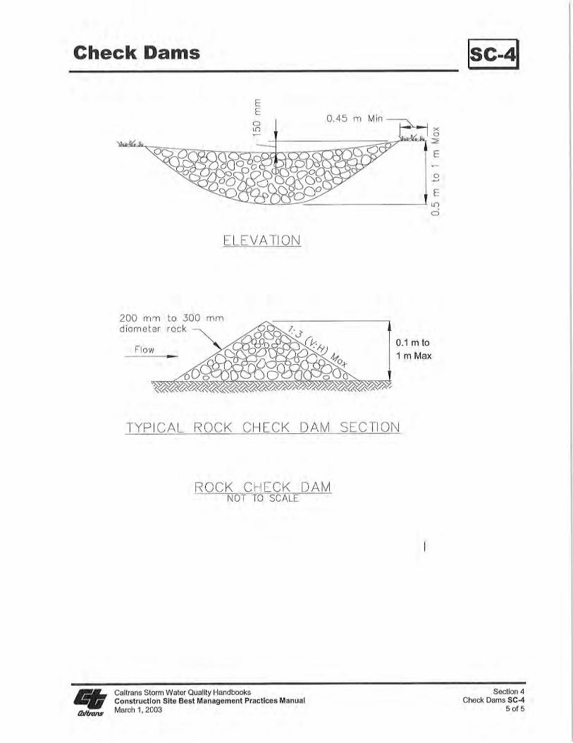

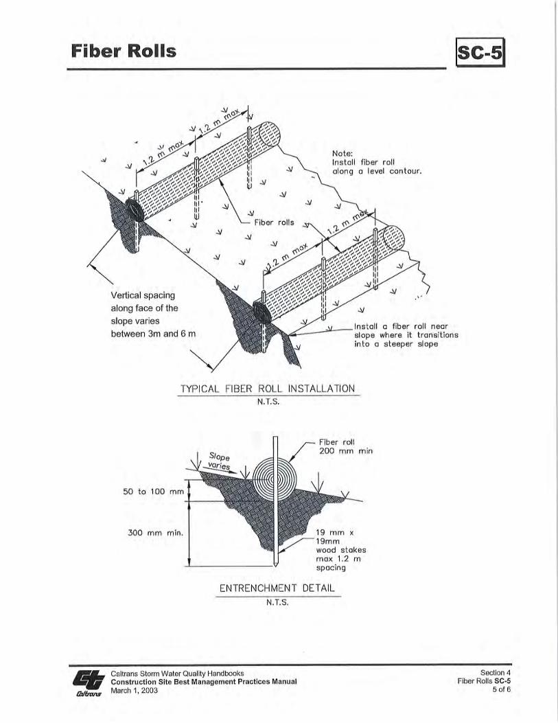
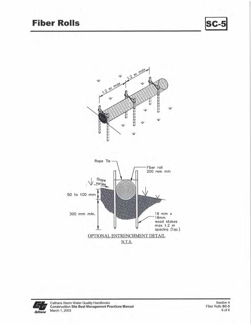
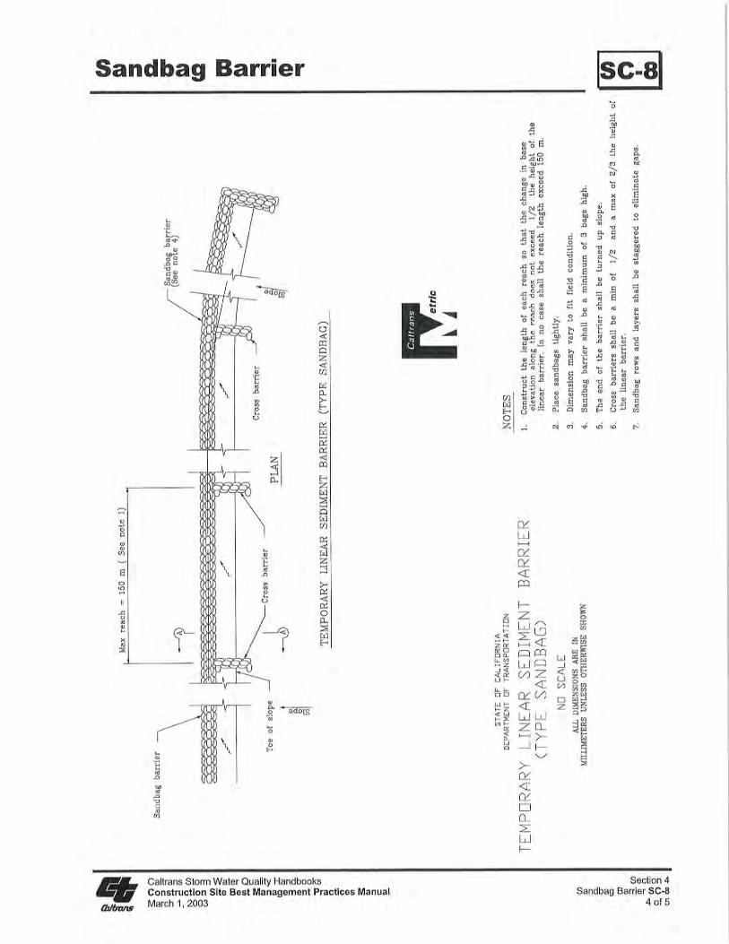
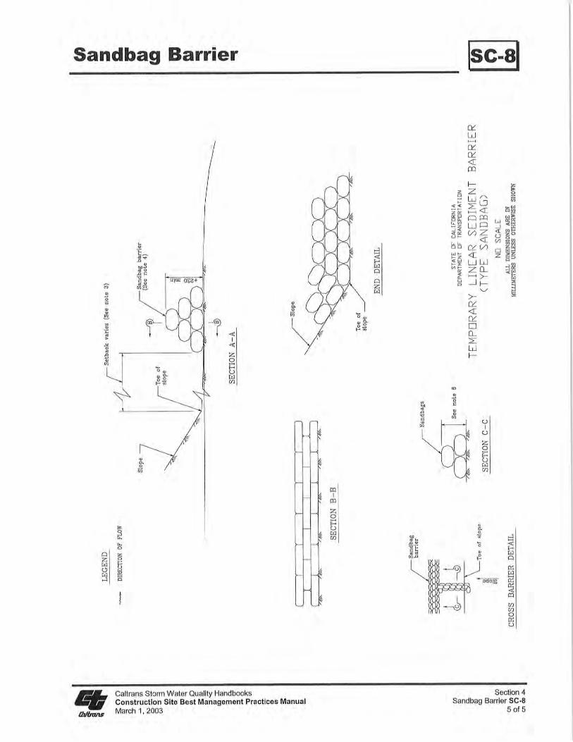

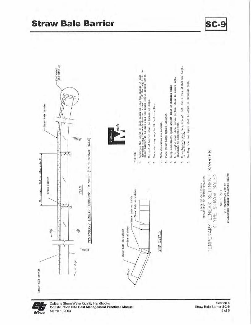
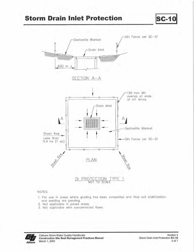
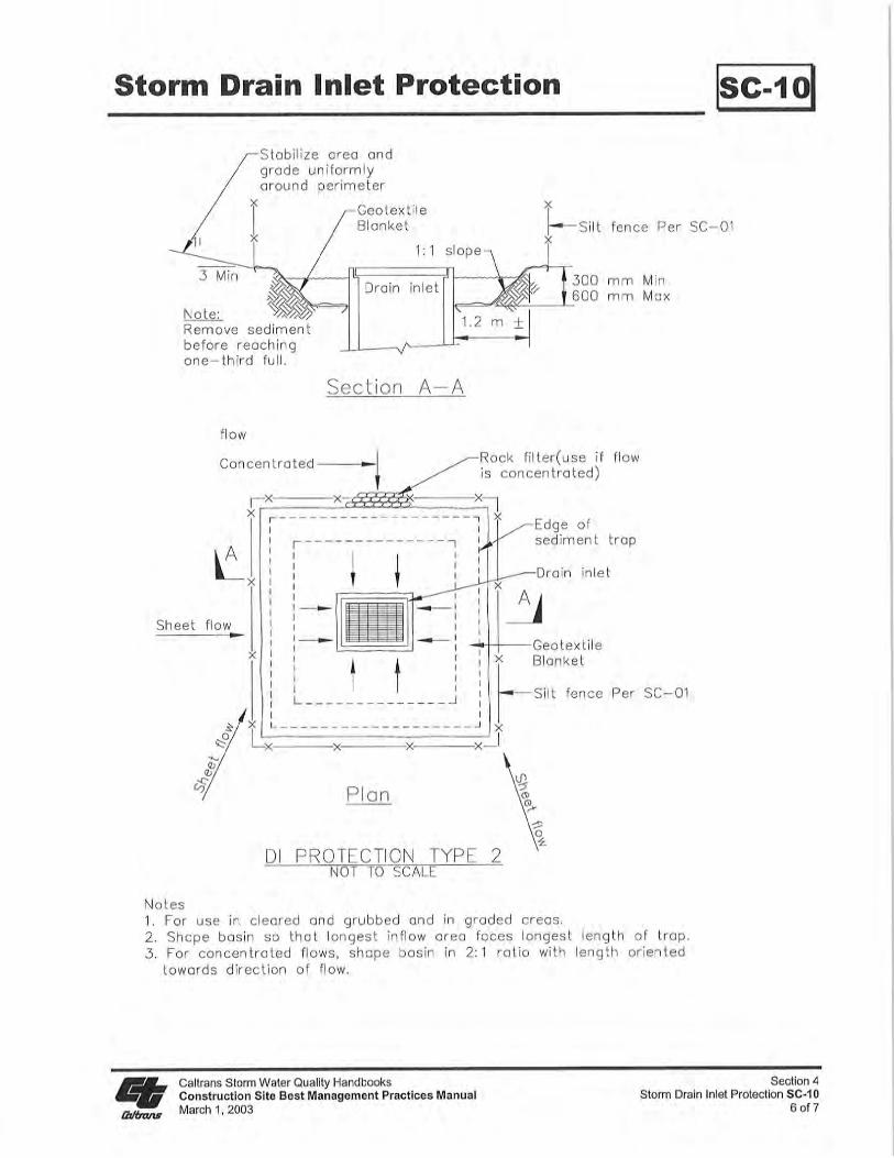
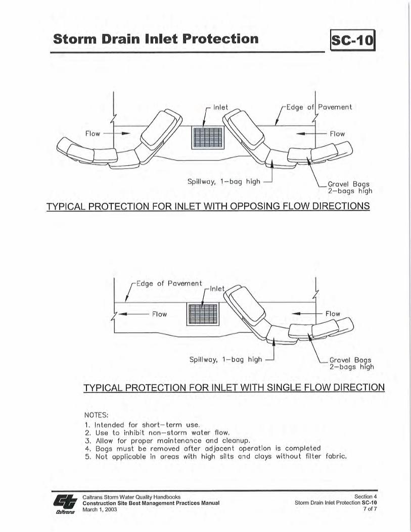
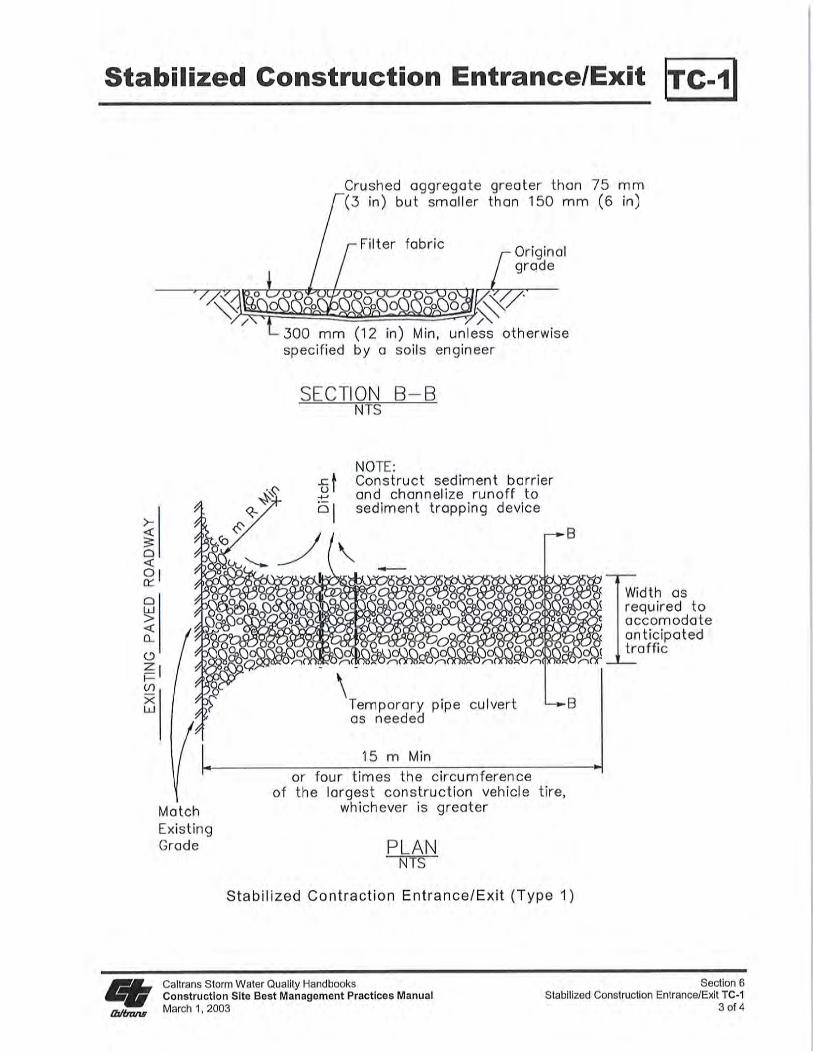
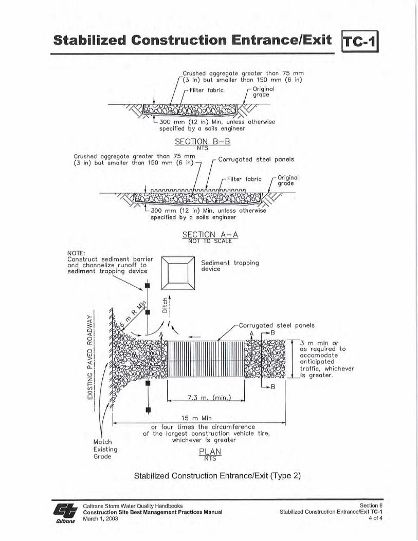
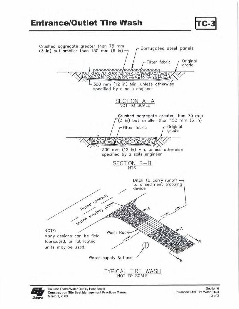
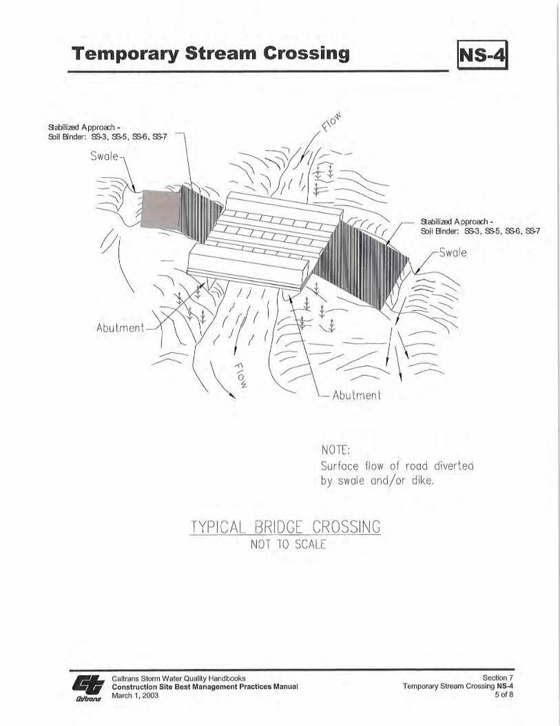
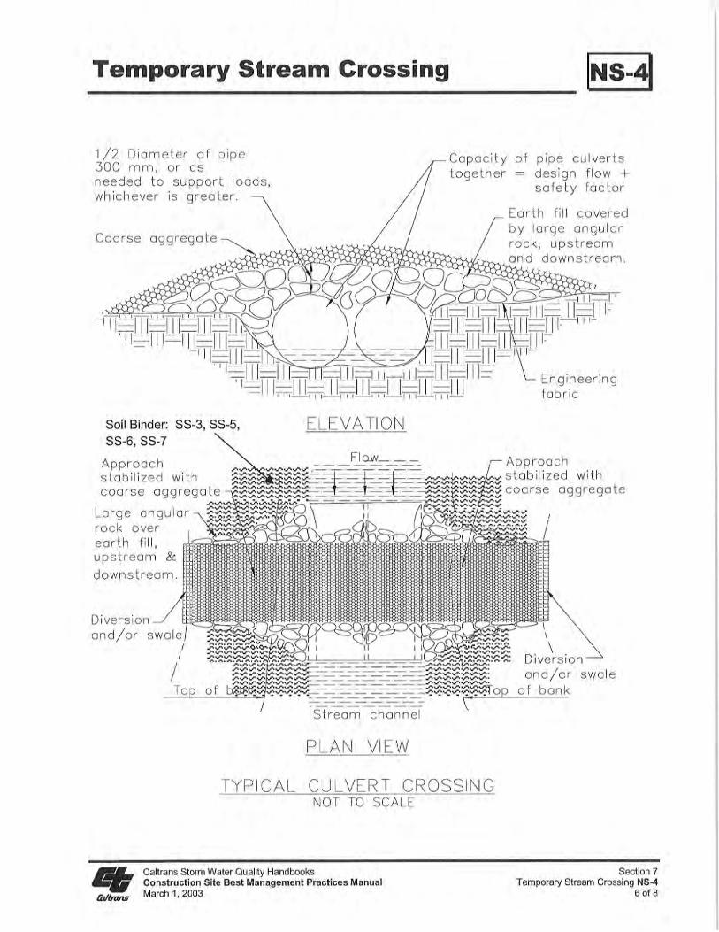
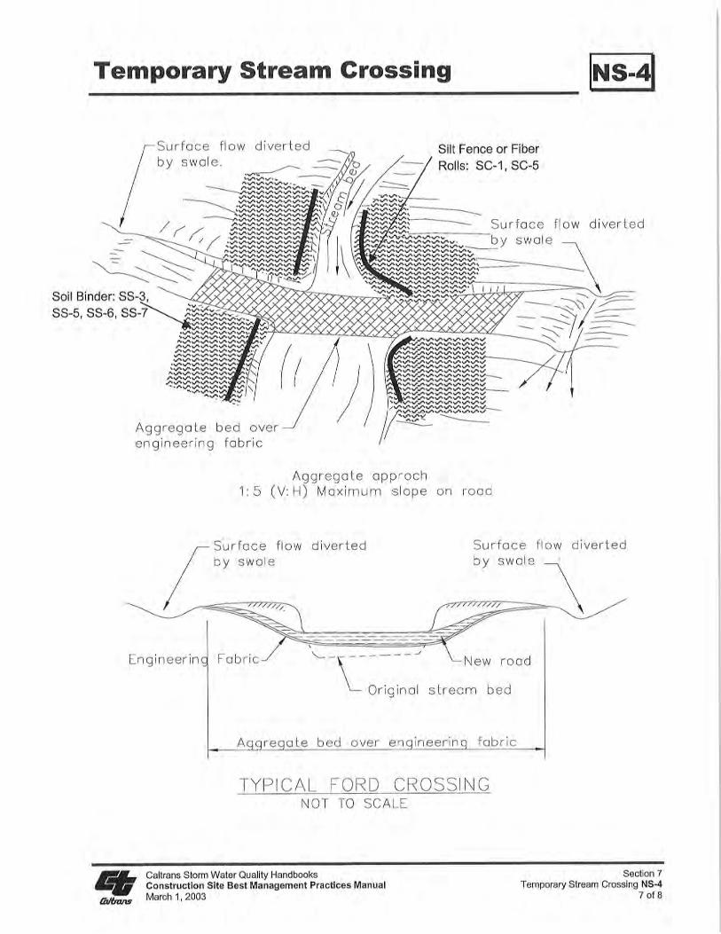
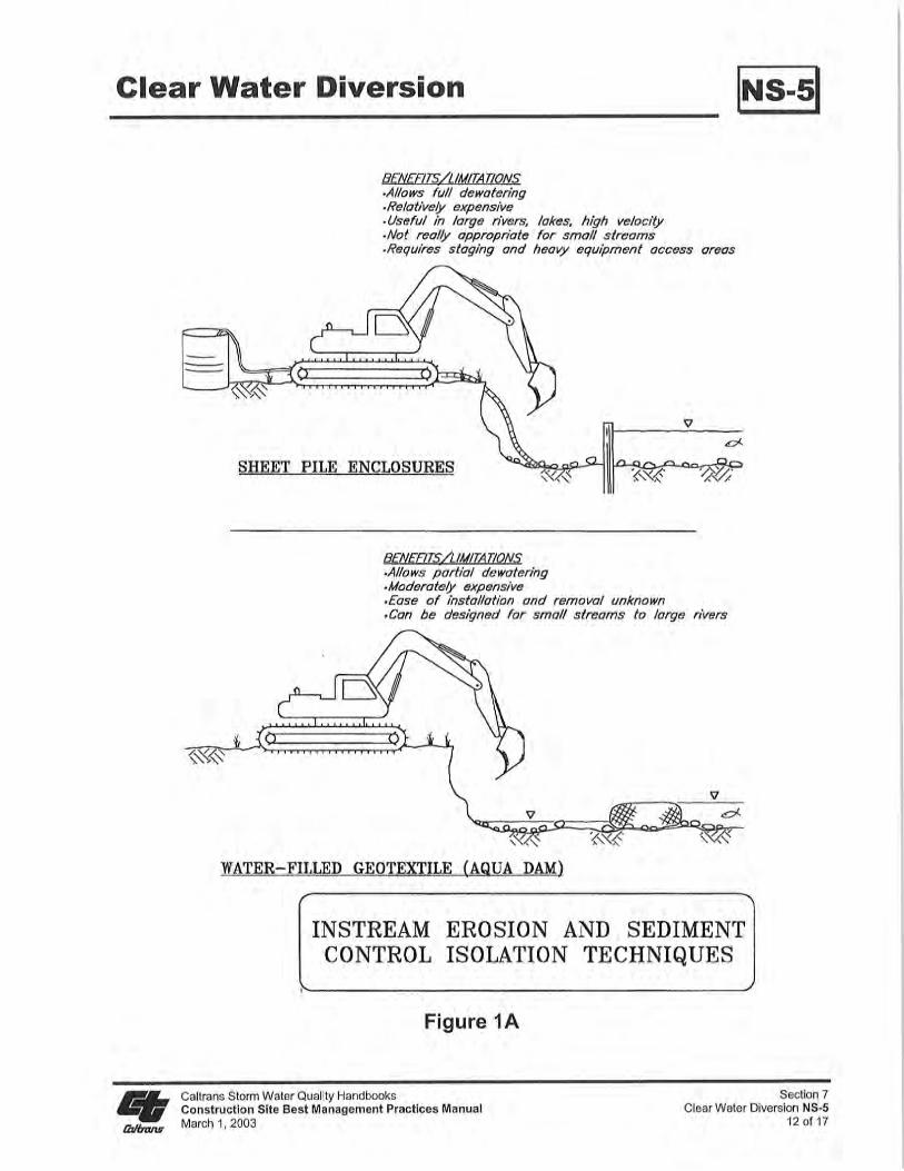
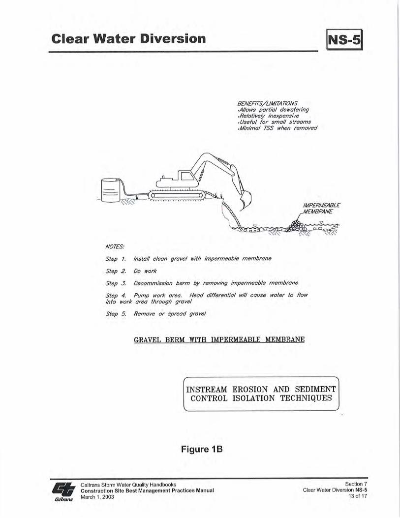
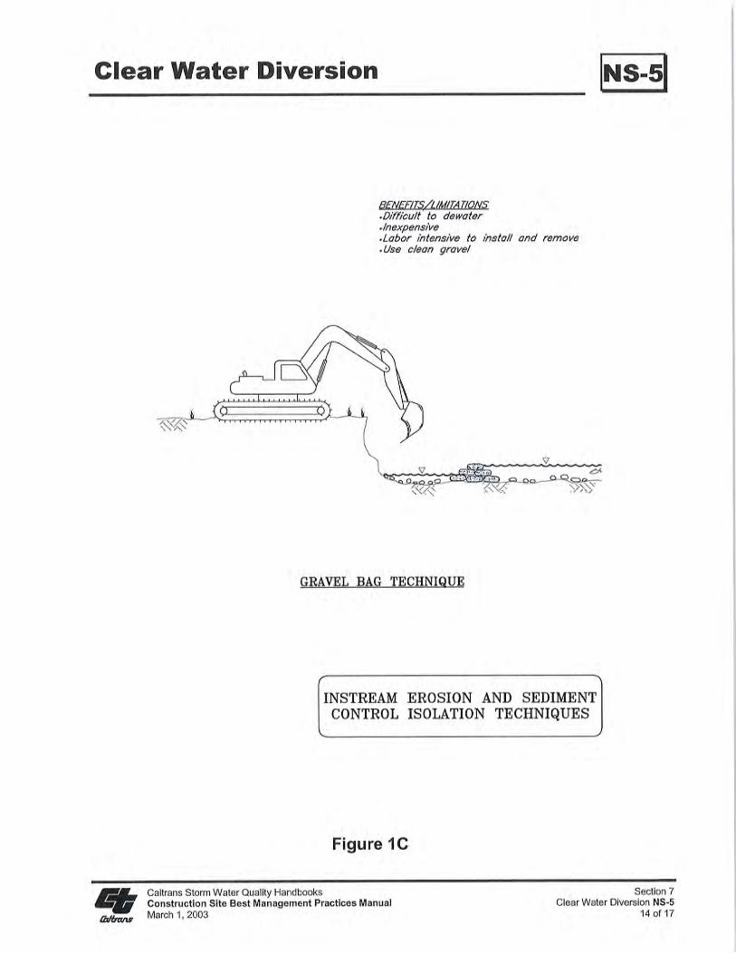
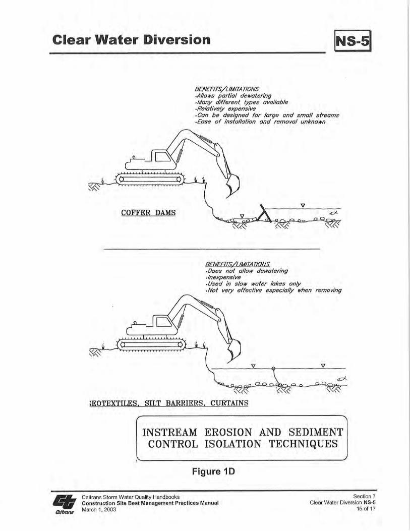

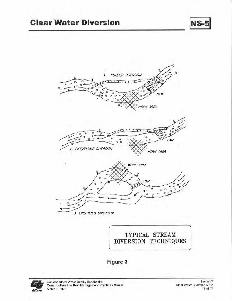
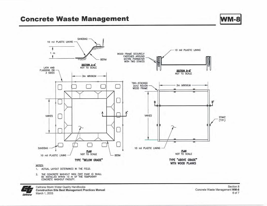
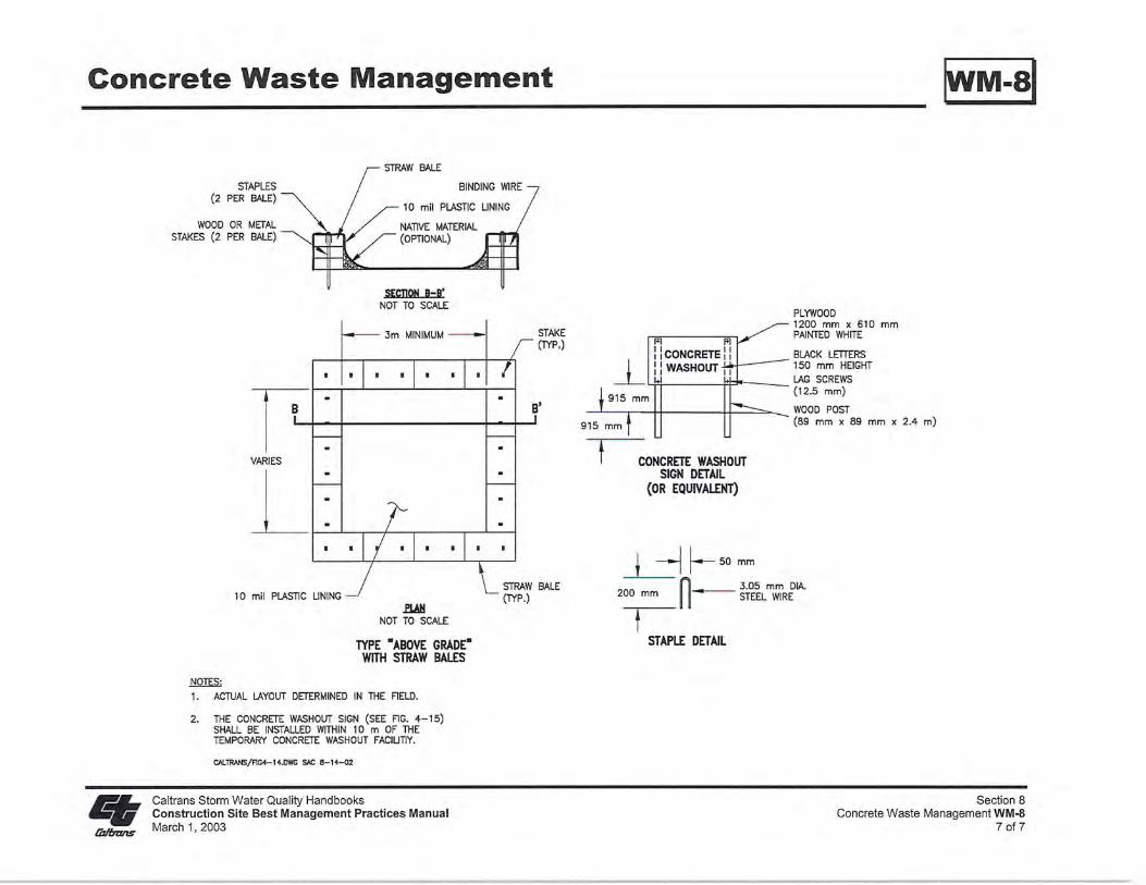

City of Sheridan Public Works Department55 Grinnell Plaza
Sheridan, WY 82501307.674.6483