design and procedures manual section 12 – storm drainage
TRANSCRIPT
Design and Procedures Manual
Section 12 – Storm Drainage Design Standards
Pump Stations
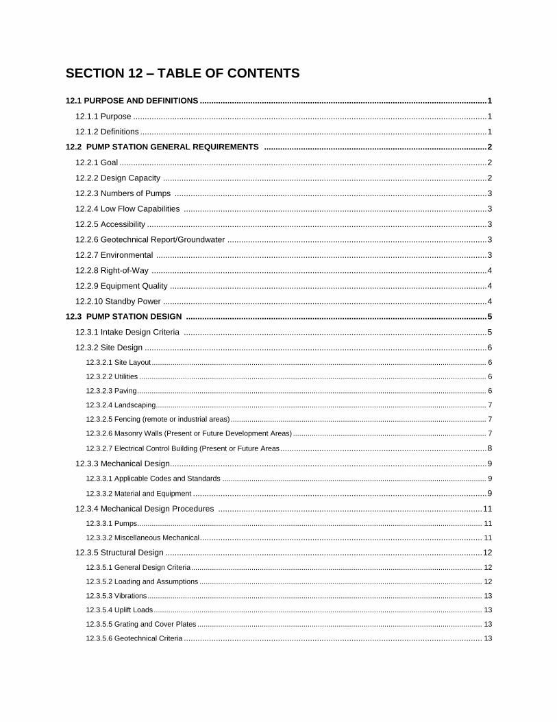
SECTION 12 – TABLE OF CONTENTS
12.1 PURPOSE AND DEFINITIONS ............................................................................................................................. 1
12.1.1 Purpose .......................................................................................................................................................... 1
12.1.2 Definitions ....................................................................................................................................................... 1
12.2 PUMP STATION GENERAL REQUIREMENTS ................................................................................................. 2
12.2.1 Goal ................................................................................................................................................................ 2
12.2.2 Design Capacity ............................................................................................................................................. 2
12.2.3 Numbers of Pumps ........................................................................................................................................ 3
12.2.4 Low Flow Capabilities .................................................................................................................................... 3
12.2.5 Accessibility .................................................................................................................................................... 3
12.2.6 Geotechnical Report/Groundwater ................................................................................................................. 3
12.2.7 Environmental ................................................................................................................................................ 3
12.2.8 Right-of-Way .................................................................................................................................................. 4
12.2.9 Equipment Quality .......................................................................................................................................... 4
12.2.10 Standby Power ............................................................................................................................................. 4
12.3 PUMP STATION DESIGN ................................................................................................................................... 5
12.3.1 Intake Design Criteria .................................................................................................................................... 5
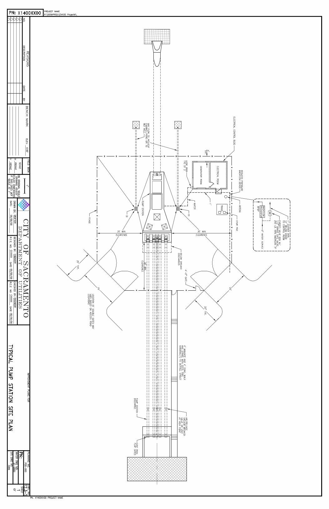
12.3.2 Site Design ..................................................................................................................................................... 6
12.3.2.1 Site Layout ................................................................................................................................................................. 6
12.3.2.2 Utilities ....................................................................................................................................................................... 6
12.3.2.3 Paving ........................................................................................................................................................................ 6
12.3.2.4 Landscaping ............................................................................................................................................................... 7
12.3.2.5 Fencing (remote or industrial areas) ........................................................................................................................... 7
12.3.2.6 Masonry Walls (Present or Future Development Areas) ............................................................................................. 7
12.3.2.7 Electrical Control Building (Present or Future Areas .......................................................................................... 8
12.3.3 Mechanical Design .......................................................................................................................................... 9
12.3.3.1 Applicable Codes and Standards ............................................................................................................................... 9
12.3.3.2 Material and Equipment ................................................................................................................................ 9
12.3.4 Mechanical Design Procedures ................................................................................................................... 11
12.3.3.1 Pumps ...................................................................................................................................................................... 11
12.3.3.2 Miscellaneous Mechanical ........................................................................................................................... 11
12.3.5 Structural Design .......................................................................................................................................... 12
12.3.5.1 General Design Criteria ............................................................................................................................................ 12
12.3.5.2 Loading and Assumptions ........................................................................................................................................ 12
12.3.5.3 Vibrations ................................................................................................................................................................. 13
12.3.5.4 Uplift Loads .............................................................................................................................................................. 13
12.3.5.5 Grating and Cover Plates ......................................................................................................................................... 13
12.3.5.6 Geotechnical Criteria .................................................................................................................................. 13
12.3.5.7 Concrete .................................................................................................................................................................. 13
12.3.5.8 Structural Metals ...................................................................................................................................................... 15
12.3.6 Electrical/Instrumentation Design.................................................................................................................. 17
12.3.6.1 Applicable Codes and Standards ............................................................................................................................. 17
12.3.6.2 Electrical Documents: Electrical Specifications ......................................................................................................... 17
12.3.6.3 Electrical Drawings ................................................................................................................................................... 17
12.3.6.4 Conduit Standards ................................................................................................................................................... 22
12.3.6.5 Wiring and Component Numbers ............................................................................................................................. 23
12.3.6.6 Equipment Tag Numbers ......................................................................................................................................... 23
12.3.6.7 Power Distribution system ........................................................................................................................................ 24
12.3.6.8 Standby Power System ............................................................................................................................................ 25
12.3.6.9 Control ..................................................................................................................................................................... 26
12.3.6.10 Lighting .................................................................................................................................................................. 27
12.3.6.11 Lighting Fixtures ..................................................................................................................................................... 27
12.3.6.12 Scada ..................................................................................................................................................................... 28
12.3.6.13 Standard Schedule Format ..................................................................................................................................... 29
12.3.6.14 Startup and Operational Requirement .................................................................................................................... 30
12.3.6.15 Record Drawings .................................................................................................................................................... 30
12.4 PUMP STATION MASTER SPECIAL PROVISIONS ........................................................................................ 31
12.5 SUBMITTAL REQUIEMENTS ........................................................................................................................... 32
12.5.1 General ........................................................................................................................................................ 32
12.5.2 Meeting Requirements ................................................................................................................................. 32
12.5.3 Submittal Requirements ............................................................................................................................... 32
12.6 AREA SPECIFIC REQUIREMENTS ................................................................................................................. 35
12.6.1 North Natomas ............................................................................................................................................. 35
APPENDIX ................................................................................................................................................................. 36
GENERAL DRAWINGS
1. Typical Pump Station Site Plan ........................................................................................................................... a1
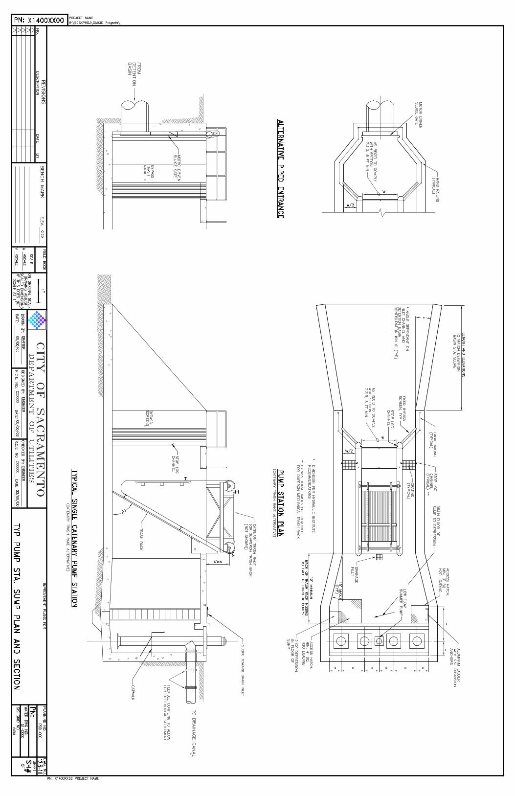
2. Typical Sump Plan and Section 1 ....................................................................................................................... a2
3. Typical Sump Plan and Section 2 ....................................................................................................................... a3
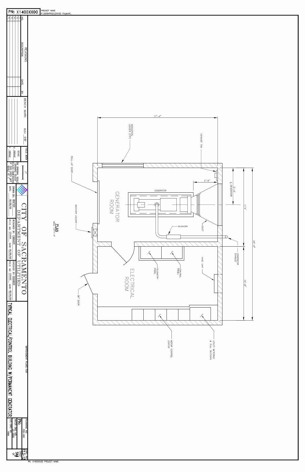
4. Typical Electrical/Control Building with Permanent Generator ............................................................................ a4
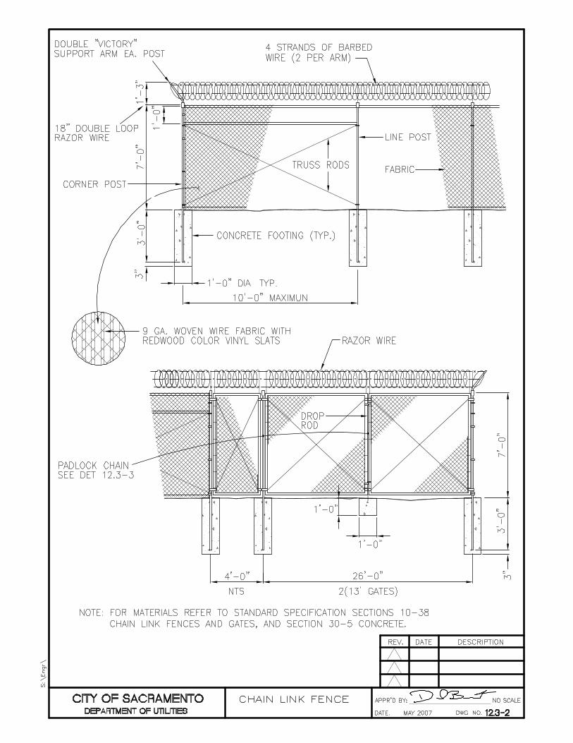
5. Chain Link Fence ................................................................................................................................................ a5
ELECTRICAL DRAWINGS
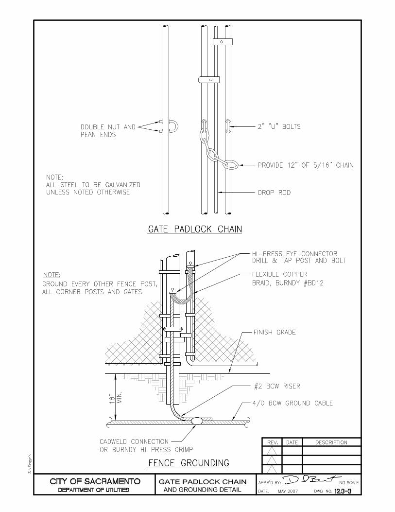
1. Gate Padlock Chain and Grounding Detail ......................................................................................................... a6
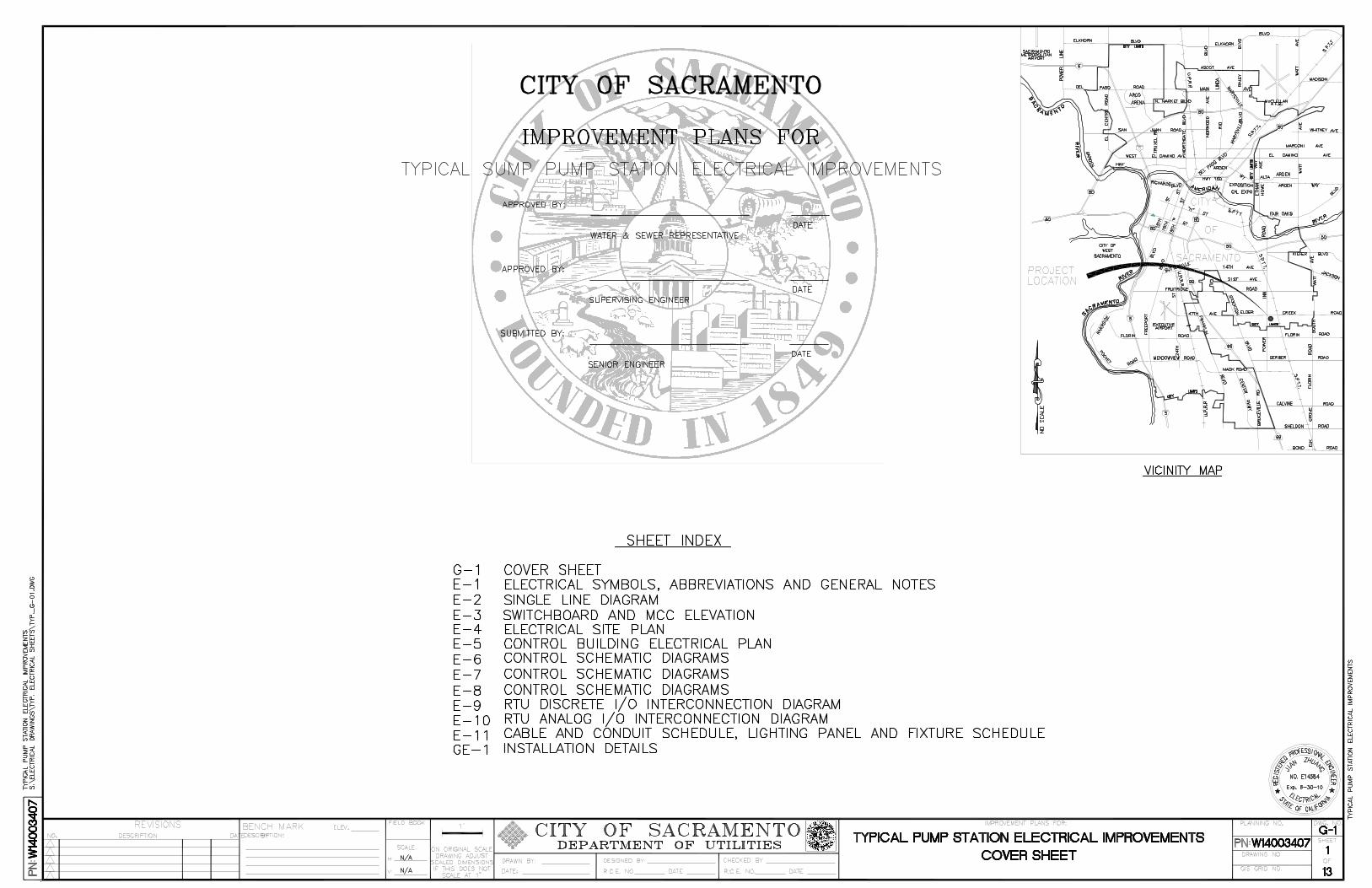
2. Typical Pump Station Electrical Improvements - Cover Sheet ............................................................................. a7
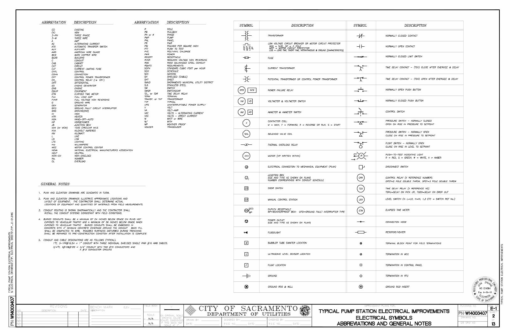
3. “ - Electrical Symbols Abbreviations and General Notes ............................................................................... a8
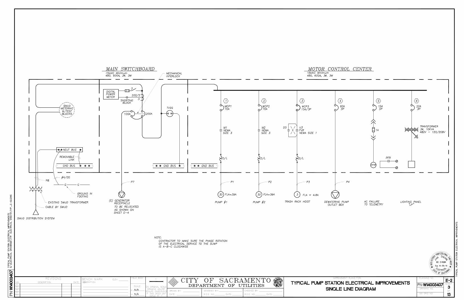
4. “ - Single Line Diagram ................................................................................................................................. a9
5. “ - Switchboard and MCC Elevation .............................................................................................................. a10
6. “ - Electrical Site Plan ................................................................................................................................... a11
7. “ - Control Building Electrical Plan ................................................................................................................ a12
8. “ - Control Schematic Diagrams ................................................................................................................... a13
9. “ - Control Schematic Diagrams ................................................................................................................... a14
10. “ - Control Schematic Diagrams .................................................................................................................. a15
11. “ - RTU Discrete I/O Interconnection Diagram ............................................................................................ a16
12. “ - RTU Analog I/O Interconnection Diagram .............................................................................................. a17
13. “ - Cable and Conduit Schedule, Lighting Panel and Fixture Schedule ....................................................... a18
14. “ - Installation Details .................................................................................................................................. a19
ARCHITECTURAL DRAWINGS
1. Site Plan - Corner Lot ....................................................................................................................................... a20
2. Site Plan – Interior Lot ....................................................................................................................................... a21
3. Security Fence Detail ........................................................................................................................................ a22
4. Tiered Fence Detail............................................................................................................................................ a23
5. Electrical Control Building - Elevation ................................................................................................................ a24
6. Electrical Control Building Elevation ................................................................................................................. a25
7. Vehicle Gate ..................................................................................................................................................... a26
12-1
SECTION 12 STORM DRAINAGE DESIGN STANDARDS -
PUMP STATIONS 9/09
12.1 PURPOSE AND DEFINITIONS 12.1.1 PURPOSES Section 12 contains general design criteria for storm drainage pump stations in the City of Sacramento and supplemental criteria for North Natomas pump stations. The criteria will be updated periodically to address new ideas and practices and the engineer, prior to designing, shall get the latest revisions, or any additional criteria not covered herein, from the Department of Utilities (DOU). The appropriate application of the criteria to specific projects is the sole responsibility of the Engineer of Record (EOR). It is expected that issues will arise which are not completely addressed in this section, and those issues may require unique solutions by the EOR. 12.1.2 DEFINITIONS The definitions in Section 11, “Storm Drainage Design Standards” apply to this section. Whenever those or the following additional terms are used, the intent and meaning shall be as defined in the “Definitions” portions of either sections 11 or 12: Hydraulic Institute Standards: American National Standard books or pamphlets published by the Hydraulic Institute copies of which can be obtained at 9 Sylvan Way, Parsippany, N.J. 07054-3802 or on the web at www.pumps.org. Pump Capacity: The capacity of a pump expressed in cubic feet per second (cfs) or gallons per minute (gpm). One cfs is equivalent to 448.8 gpm. Total Dynamic Head (TDH): The term TDH consists of the sum of three items: 1. Static Head This is the height that the water will be raised. 2. Friction Head The friction head includes all losses in the discharge line such as pipe
friction, column and elbow losses, valve and bend losses, junction losses, transition losses and exit losses.
3. Velocity Head This is the kinetic energy the water possesses due to its flow. It is equal
to V2/2g.

12-2
12.2 PUMP STATION GENERAL REQUIREMENTS
12.2.1 GOAL The primary goal of Section 12 is to develop uniformity, establish minimum quality requirements, and insure superior operation and maintainability for all drainage pump stations designed and constructed in behalf of the City of Sacramento Department of Utilities. 12.2.2 DESIGN CAPACITY Pump stations shall be designed for the most economical combination of storage and pumping capacity such that the upstream and downstream HGL can be contained within the drainage system and the maximum water surface elevations maintained as shown on Figure 12.2-1. The terms “100 Year” and “10 Year” refer to the water surface elevation associated with the 100 year or 10 year storm at any point in the basin. 10/100 YEAR CRITERIA Figure 12.2-1
12-3
12.2.3 NUMBERS OF PUMPS Drainage pump stations shall have enough discharge capacity to maintain the water surface elevations shown in Figure 12.2-1 in the tributary basin(s) but shall not adversely impact any other area or increase flooding elsewhere. Often, three pumps are optimal in accomplishing this, but the EOR shall determine the correct number of pumps. In all cases a redundant pump shall be provided which has equal or greater capacity than the largest pump and which shall act as a backup for reliability and maintenance purposes. Swithgear shall be designed to provide for the regular operation of all the pumps such that pumps sequentially serve as the redundant pump. A separate pump dedicated to low flow shall not be included in this rotation. The design capacities of the several pumps shall be based on output capacity equal to 75% of rated capacity, due to the inevitable wear and tear on the pumps. If metering equipment is provided that yields reliable, real time output data, a design capacity equal to 90% of rated capacity may be used. 12.2.4 LOW FLOW CAPABILITIES In addition to the pumps provided for higher flows, a separate low flow pump of adequate capacity shall be provided to convey calculated low and dry weather flows. Low flow pumps may also be incorporated into a pump-back system for water quality requirements and to control groundwater. There are limits on the amount of groundwater that is allowed to enter the pump station as indicated in this section. 12.2.5 ACCESSIBILITY The drainage pump station shall be designed to allow easy access for maintenance purposes. To accomplish this the engineer shall meet with Department of Utilities early in the design process. A typical site plan for a new drainage pump station is shown on Figure 12.3-1. 12.2.6 GEOTECHNICAL REPORT/GROUNDWATER A geotechnical report for the drainage pump station site, including groundwater considerations, shall be provided and shall conform to the applicable requirements listed in Section 11, herein. Recommendations for resisting uplift forces resulting from high groundwater shall also be included in the report. 12.2.7 ENVIRONMENTAL Aesthetics: The aesthetic appearance of the drainage pump station and site must be carefully planned and shall appropriately blend with the surrounding community See Figures 12.3-6 through 12.3-10. Noise levels: Pump station noise generated at maximum operating levels shall comply with Chapter 68 of the Sacramento City Code. All diesel engines, generators and pumps shall be enclosed and noise controlled. Water service: All pump stations shall be provided with a minimum 2 inch water service that will be used for wash down purposes and may be required as part of the pressure transmitter.
Permits: Pump station design, construction and operation shall adhere to the City’s NPDES permit requirements and shall be subject to all agencies having regulatory authority and their permitting requirements including, but not limited to the following:
12-4
California State Fish and Game State Reclamation Board Reclamation District 1000 American River Flood Control District
Corps of Engineers Sacramento Metropolitan Air Quality Management Division Sacramento Municipal Utility District
12.2.8 RIGHT-OF-WAY Sufficient right-of-way shall be provided to allow for all pump station facilities, for the movement of large vehicles within the pump station, adequate ingress and egress during storm periods, to perform operation and maintenance activities, and for landscaping in keeping with the aesthetic of the surrounding neighborhood. The minimum width of the entry and exit roads shall be 15 feet. 12.2.9 EQUIPMENT QUALITY The drainage pump station shall be constructed to operate successfully during the worst storm emergencies, and as such, the equipment installed in these stations must be highly reliable, of the type and construction that will require a minimum of maintenance. Since the equipment might stand idle for long periods of time and will be subject to variations in temperature and condensation, all equipment shall be selected to provide inherent protection against these deteriorating elements. 12.2.10 STANDBY POWER The drainage pump stations shall be provided with standby power capable of running the station at its design discharge capacity. The standby power shall be a stationary generator. If the starting and running power requirement of the pump station exceeds 350 kilowatts, a stationary generator shall be provided. The stationary generator shall be as described in this section.
12-5
12.3 PUMP STATION DESIGN
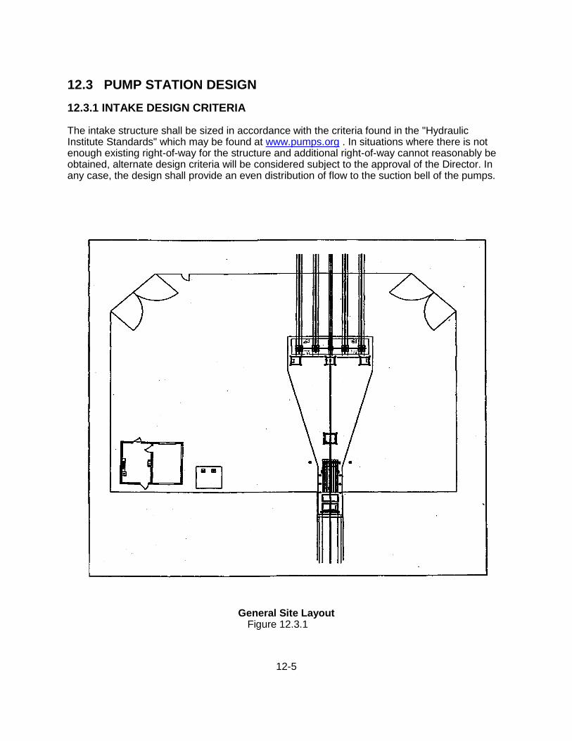
12.3.1 INTAKE DESIGN CRITERIA The intake structure shall be sized in accordance with the criteria found in the "Hydraulic Institute Standards" which may be found at www.pumps.org . In situations where there is not enough existing right-of-way for the structure and additional right-of-way cannot reasonably be obtained, alternate design criteria will be considered subject to the approval of the Director. In any case, the design shall provide an even distribution of flow to the suction bell of the pumps.
General Site Layout
Figure 12.3.1
12-6
12.3.2 Site Design 12.3.2.1 Site Layout The site shall be designed to provide adequate space to accommodate the sump structure, support structures, and access for maintenance equipment, as well as appropriate access and operating space for vehicles and pump removal equipment (i.e. cranes, hoists, and trucks). General site layout requirements are illustrated on Figure 12.3 -1. The minimum width of entry and exit roads shall be 15 feet. Station set backs from the toe of an adjacent levee shall, at a minimum, comply with permitting agency requirements and shall allow for levee enlargement on the landward side. The levee enlargement shall accommodate elevating the levee three feet (3') with a side slope 2 horizontal to 1 vertical (2:1). For new pump stations, the finish surface of the site and the access road to the pumping station site shall be a minimum of 2 feet in elevation above either the 100-year flood elevation or 2 feet above the high point of the natural ground surrounding the project site, whichever is higher. For improvements to existing pump stations, all motors and electrical equipment shall be elevated a minimum of 2 feet above the 100-year flood elevation. Alternatively, a flood wall shall be constructed to a height of 2 feet above the 100-year water surface in such a configuration that it will protect all of the equipment. The City may require construction to higher elevations than those indicated above if deemed necessary to avoid flooding. 12.3.2.2 Utilities Power: Underground 480 volt, or 240 volt, 3 phase, 4 wire service will be required at the pumping station site. For additional information see Section 12.3.5. Telephone: Telephone service shall be required at each pump station site. Telephone lines will terminate at the telephone termination cabinet. Water: A 2-inch potable water service shall be provided to the site for wash down and to provide a port for a possible pressure transmitter. The service line shall be equipped with an approved reduced-pressure-principle backflow preventer. Two 1 inch water service lines with 1" hose bibs shall be located as shown on Figure 12.3 -1. Telemetry: Telemetry Shall be provided at each pump station site. For additional information see Section 12.3.5. 12.3.2.3 Paving All vehicle access roads and the fenced area of pump stations shall be paved with asphaltic concrete and aggregate base over subgrade compacted to 95% relative compaction. The pavement structural section shall be designed in accordance with the Caltrans gravel equivalency method and shall be based on a traffic index (T.I.) of 6.0 and on the R-value of the soil as determined by a geothechnical engineer. Special considerations shall be made for the design of pavement sections in areas where expansive soils exist, by incorporating geogrids or
12-7
other techniques. The minimum pavement structural section, regardless of soil conditions and other parameters shall be 3-inches of asphalt concrete over 8-inches of aggregate base. 12.3.2.4 Landscaping No landscaping shall be provided within the fenced perimeter of the pump station. Landscaping shall, however be provided outside the fenced perimeter which blends appropriately with the surrounding neighborhood. Landscaping shall consist of drought tolerant trees, shrubs, and ground cover, designed to maximize water conservation. Refer to Section 11 for landscaping of detention facilities adjacent to or integral with pump stations. 12.3.2.5 Fencing (remote or industrial areas): Unless fencing of reinforced masonry and/or brick units is required, in remote or industrial areas, chain link fencing shall be provided and shall conform to Figures 12.3 -2 and 12.3 -3, Sections 10-38 and 31 of the Standard Specifications, and shall be provided with vinyl slats of an appropriate color consistent with the surroundings. The top of the chain link fence and gates shall include ―victory‖ or double arms with barbed wire along each side (top and bottom of arms – four strands total) and 18-inch diameter razor wire at double density (1 loop per 9 inches, 25 feet per roll). The razor wire is to be connected to the barbed wire supports at appropriate intervals and to the chain link fabric at every loop. Connections shall be 9gage galvanized steel hog rings or approved equal. Variations to the fencing requirement in remote areas may be necessary in order to blend into surroundings and/or conform to planning strategies. Such variations shall be approved by the Director. 12.3.2.6 Masonry Walls (Present or Future Development Areas): Site enclosures for pump stations not in industrial or remote areas shall be reinforced masonry and/or brick units per Figures 12.3-4 through 12.3-10. In all areas within the public view and adjacent to public walkways, a 7’ high concrete masonry wall shall be constructed. The concrete masonry wall shall have pilasters spaced equally along the length of the fenced areas at approximately 12-foot intervals. Pilasters shall be constructed of 8x8x16 split face concrete masonry units, 24 inches square, 84 inches tall with a precast masonry cap. The concrete masonry wall shall consist of 8x8x16 concrete masonry units, 8 rows split face of running course, topped with 2 rows of ground face concrete masonry units of stack course with a 4‖ precast masonry cap. Color of concrete masonry units to be selected from full range of manufacturer’s colors by the Director. Outdoor lighting shall be installed on the inside face of the pilaster, sufficient to adequately illuminate the sump station. Decorative lighting shall be installed on the public face of the pilaster, sufficient to illuminate the walkway and deter defacement of the perimeter masonry wall.
12-8
At all areas where a masonry fence is inappropriate, yet public access is to be restricted, a metal security fence shall be installed. Security fencing shall consist of an electro-forged welded steel panel, equal to Metalco ―Grigliato B‖ by Amesco, Inc., 2 7/16‖ x 2 19/32‖ mesh, 31/32‖ x 1/8‖ main bar, 3/16‖ cross rod, polyester powder coated, color to be selected from manufacturer’s full range of colors approved by the Director. No physical deterrent to climbing the fence shall be installed, unless security situations mandate it. Security fencing shall be placed similar to Figure 12.3-5. Some areas may incorporate a tiered fence design to accommodate surface elevation variations. Tiered fence shall conform to Figure 12.3-7 and consist of an 18‖ high masonry wall placed at a distance in front of the 7-foot high masonry wall to be specified on the Site Plan. This wall shall consist of 8x8x16 concrete masonry units, 2 rows split face of running course and 1 row of ground face concrete masonry units of stack course with a 2‖ precast masonry cap. Color of concrete masonry units to be selected from full range of manufacturer’s colors by the Director. Vehicle entry and pedestrian gates shall conform to Figure 12.3-10. Construction shall be equal to Metalco ―Halley‖ by Amesco, Inc. Frame shall be constructed of steel tube 1 ½‖ x 1 ½‖, wall thickness 1/8‖. The infill shall be a wire grid made of steel wire 9 /64‖ with a mesh size 1 ½‖ x 1 ½‖. The wire grid shall be welded to the frame. Wires shall be welded at every crossing. A diagonal inserted flat steel bar ¾‖ x 3/16‖ shall be welded into the frame and onto the wire grid at every crossing and at each side of the wire grid. All main components shall be polyester powder coated, the color to be selected from manufacturer’s full range of colors by the Director. Provide vehicle gate electrical operation mechanism and lockable hardware approved by City. 12.3.2.7 Electrical Control Building (Present and Future Areas): All Electrical Control Buildings for sump stations in residential areas shall conform to Figure 12.3-8. The Electrical Control Building shall be located at the corner of the sump station site to permit two walls to align with the perimeter masonry fence or chain link fence. All roof and wall attachments or protrusions are permitted only on the two sides not aligned with the perimeter fence. Walls shall be constructed of 8x8x16 concrete masonry units, 18 rows split face of running course, 2 rows of colored, smooth concrete masonry units of stack course with an 8‖ precast masonry cornice. Roofing material shall consist of concrete tile with a roof slope of 5:12. Concrete tile shall be equal to Lifetile ColorThru ―Classic Capri‖. Color of concrete tile to be selected from manufacturer’s full range of colors by the Director. The Electrical Control Building shall be designed to permit only one opening for ventilation of equipment on any wall accessible to the public. This opening shall be covered with metal frame and screen. Construction of the metal frame and screen shall be equal to Metalco ―Halley‖ by Amesco, Inc. Frame shall be constructed of steel tube 1 ½‖ x 1 ½‖, wall thickness 1/8‖. The infill shall be a wire grid made of steel wire 9 /64‖ with a mesh size 1 ½‖ x 1 ½‖. The wire grid shall be welded to the frame. Wires shall be welded at every crossing. A diagonal inserted flat steel bar ¾‖ x 3/16‖ shall be welded into the frame and onto the wire grid at every crossing and at each side of the wire grid. All main components shall be polyester powder coated, color to be selected from manufacturer’s full range of colors by the Director.
12-9
12.3.3 Mechanical Design 12.3.3.1 Applicable Codes and Standards: Mechanical systems shall be designed and built in accordance with applicable portions of the following codes and standards: 1. California Building Code (CBC), 2007 Edition 2. Uniform Mechanical Code (UMC), 2006 Edition 3. Hydraulic Institute Standards (ANSI/HI) 4. Anti-Friction Bearing Manufacturers Association (AFMBA) Standards 5. American Society for Testing and Materials (ASTM) Standards 6. Occupation and Health Administration (OSHA) Standards, latest edition. 12.3.3.2 Materials and Equipment: 1. Pumps: All drainage pumps shall be vertical, enclosed line-shaft, oil-lubricated pumps 2. Driver Type: The pump motor driving shall be electrical, constant-speed or variable
frequency drive, and weatherproof. For pump motors over 100 horse power, a soft start starter shall be included in the motor control center.
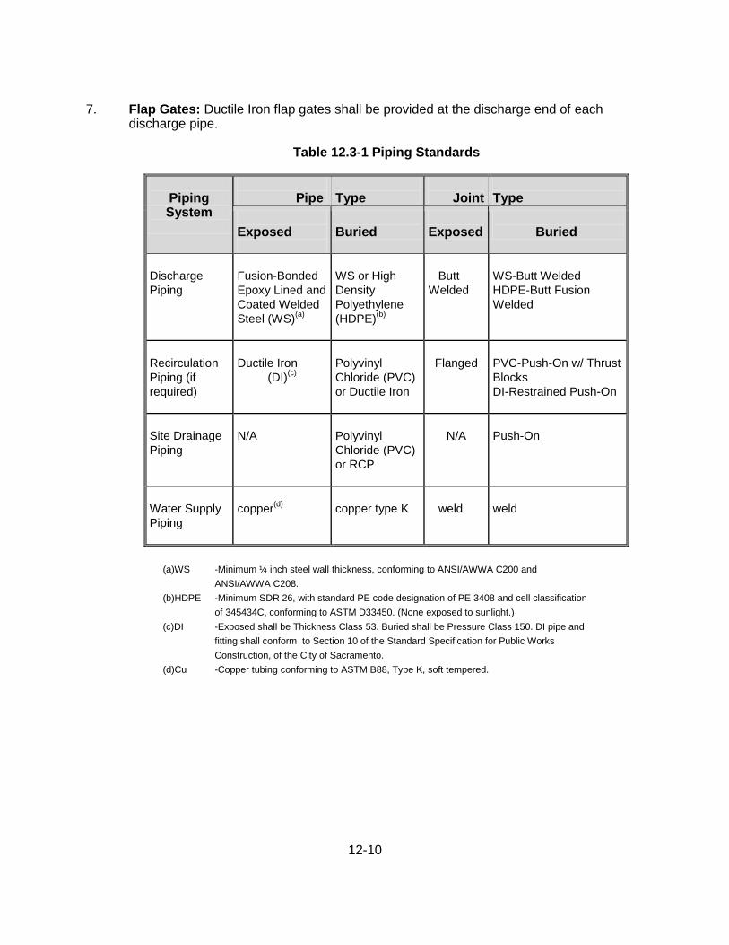
3. Piping: Piping shall conform to the schedule as listed in Table 12.3-1. 4. Mechanical Trash Rack: In general, each station shall be equipped with at least one
heavy-duty, continuous traveling, Catenary type mechanical trash rack. The unit shall be of the two-shaft Catenary type, with front leaning rake beams that return along a guided path in front of the trash rack after dumping the trash near the top of their travel. As alternatives to a Catenary type trash rack, stations may be equipped with at least one heavy-duty Duperon Flexrake trash rack. Such trash racks shall conform to the manufacturers requirements and recommendations.
5. Fixed Bypass Screens: In conjunction with the mechanical trash racks, fixed bypass
screens shall be installed with the Catenary trash rack, as shown on Figure 12.3-11. The width of the channel at each of the two fixed bypass screens shall be at least one-half the width of the mechanical trash rack. The fixed bypass screens shall have cow catches located at their bottom and mid-point. Fixed bypass screens are not required on one or both sides of Duperon trash racks, provided velocity criteria are satisfied per Section 12.3.4.2.
6. Dump Trailer: At the option of the Director, each mechanical trash rack shall be
equipped with a 5’ wide by 10’ long dual-axle dump trailer with a 7,000 pound gross vehicle weight capacity. The trailer shall be all-steel construction and equipped with 4-wheel electric brakes, 12-volt hydraulic system, 48-inch tall metal sides, a split rear gate, low rider package, key lock, and adjustable pintle eye coupler rated at 6 ton capacity. The trailer shall meet all Federal and California State Department of Transportation requirements for on-road towed vehicles.
12-10
7. Flap Gates: Ductile Iron flap gates shall be provided at the discharge end of each discharge pipe.
Table 12.3-1 Piping Standards
Piping System
Pipe
Type
Joint
Type
Exposed Exposed
Buried
Exposed
Buried
Discharge
Piping
Fusion-Bonded
Epoxy Lined and
Coated Welded
Steel (WS)(a)
WS or High
Density
Polyethylene
(HDPE)(b)
Butt
Welded
WS-Butt Welded
HDPE-Butt Fusion
Welded
Recirculation
Piping (if
required)
Ductile Iron
(DI)(c)
Polyvinyl
Chloride (PVC)
or Ductile Iron
Flanged
PVC-Push-On w/ Thrust
Blocks
DI-Restrained Push-On
Site Drainage
Piping
N/A
Polyvinyl
Chloride (PVC)
or RCP
N/A
Push-On
Water Supply
Piping
copper(d)
copper type K
weld
weld
(a)WS -Minimum ¼ inch steel wall thickness, conforming to ANSI/AWWA C200 and
ANSI/AWWA C208.
(b)HDPE -Minimum SDR 26, with standard PE code designation of PE 3408 and cell classification
of 345434C, conforming to ASTM D33450. (None exposed to sunlight.)
(c)DI -Exposed shall be Thickness Class 53. Buried shall be Pressure Class 150. DI pipe and
fitting shall conform to Section 10 of the Standard Specification for Public Works
Construction, of the City of Sacramento.
(d)Cu -Copper tubing conforming to ASTM B88, Type K, soft tempered.
12-11
12.3.4 Mechanical Design Procedures 12.3.4.1 Pumps The procedure to follow when designing a pump station are found in Appendix "B". Exceptions or additions to this procedure are as follows: 1. Number of pumps: The size and number of pumps will depend on the flow into the
pump station, the total dynamic head, the size of the wet well or forebay, and any limitation on the discharge into receiving waters. An additional (redundant) pump, identical to the largest pump istalled, shall be also be installed to act as a stand-by for emergency and maintenance purposes. Sizing of pumps shall be based on performance at 75% of rated capacity, or 90% of rated capacity, if acceptable flow meters are provided.
2. Pump Control: Both a float switch and a sonic device, equal to ―level Rat‖ transducer,
shall be provided for pump control. 3. Low Flow Pumping Capacity: If the pump station cannot gravity flow during low
receiving water stages, a low-flow pump shall be provided. The low flow pump shall be capable of handling the summer flows and any groundwater that infiltrates into the drainage system. Summer flow shall be assumed to equal 0.002 cfs per acre of service area plus groundwater infiltration, calculated as directed herein.
4. Pump Calculations: The total dynamic head shall be calculated using the Hazen-
Williams formula, assuming a Ch of 140. Total dynamic head calculations shall include pump column losses, discharge elbow losses, discharge piping losses, minor losses including valve losses, velocity head, and static head. It is recommended that calculations be made with an electronic spread sheet or other computer program, clearly delineated to allow easy review of the design. The designer shall submit a copy of all background calculations, along with graphs showing the pump curve vs. system curve.
12.3.4.2 Miscellaneous Mechanical 1. Provisions for Differential Settlement: Two Dresser or equal mechanical couplings
shall be installed on each discharge pipe near the structure to allow for differential settlement of the pump station structure and discharge piping.
2. Discharge Piping: The backflow of water from the receiving canal into the pump station
shall be prevented, in addition to installing a flap gate, by establishing the invert elevation of the discharge pipe at its highest point above the 100-year flood elevation in receiving canal, and installing an air release/siphon breaker valve or vent at that point.
3. Minimum Cover: Minimum cover over discharge piping shall be according to permit
requirements, 36 inches, or one pipe diameter, whichever is greater. 4. Equipment Mounting: All piping and equipment shall be mounted in accordance with the
manufacturer’s recommendations, the California Building Code (2007) (CBC), and industry standard requirements. Each piece of equipment shall be designed for lateral forces for overturning, pullout, and shear for Seismic Zone 3 in accordance with the CBC,

12-12
the minimum lateral force required by the manufacturer of the equipment, or a lateral force of 60% of the operating weight of the equipment, whichever is greater.
5. Sizing of Mechanical Trash Rack: Mechanical trash racks shall have 2-inch clear
openings between bars. The mechanical trash rack shall be designed so that the velocity through the clean rack does not exceed 1.0 foot per second at the minimum water level with one peak-flow pump in operation, and 2.0 feet per second at other operating conditions. No flow shall be assumed to occur through the fixed trash racks. The designer shall check the velocity through the rack at each pump on/off level. The minimum width of the screen shall be six feet. The motor voltage for the mechanical trash rack shall be verified by the City.
12.3.5 Structural Design 12.3.5.1 General Design Criteria: Structural components shall be designed and constructed in strict conformance with the following codes and standards: 1. California Building Code, 2007 Edition (CBC) 2. Building Code Requirements for Reinforced Concrete (ACI 18-95) and Commentary
(ACI 318R-95) 3. Manual of Steel Construction Allowable Stress Design, 9th Edition American Institute of
Steel Construction (AISC) 4. Design Considerations for Environmental Engineering Concrete Structures (ACI 350.4R) 5. Occupational Safety and Health Administration (OSHA) Standards 12.3.5.2 Loading and Assumptions: The most severe concentration, distribution, and combination of design loads and forces shall be considered in the design. The design shall conform to all the requirements of the UBC, including load combinations. The following loads and their combinations shall be used for the structural design: 1. Dead Loads: The loads are the weight of all fixed construction, equipment, piping,
equipment bases, soil overburden, and all permanent non-removable stationary construction. The numerical values to be used for the dead load of well-defined components of a structure are documented in the following publications:
a. AISC Manual of Steel Construction b. CRSI Design Handbook c. Manufacturer’s Catalogs
2. Live Loads: The live loads consist of all loads (other than dead loads) that shall
be considered in the design to satisfy the CBC and other applicable code requirements. The minimum live loads to be considered shall be H20 loading and shall include impact. The live loads to be considered shall allow equipment to be moved to other locations or additional equipment to be added in the future to a reasonable extent. Live loads considered for design shall be indicated on the structural drawings.
3. Seismic Loads: The seismic loads for all structures shall be in accordance with
CBC Zone 3, I=1.25. Hydrodynamic and earth pressures resulting from earthquakes shall also be considered.

12-13
Seismic design for the support of nonstructural elements, such as piping, conduit, and equipment, shall be based on CBC using the same Importance Factors as the structure they are associated with. The seismic design shall consider:
a. Anchorage of equipment b. Seismic restraint of equipment and piping c. Flexibility and ductility of piping systems d. Structural compatibility between pump stations and equipment, conduit, and
piping. 4. Liquid Loads: Pump station walls subjected to liquid pressures shall be designed
for maximum liquid levels with the following conditions:
a. At maximum design liquid level, and no backfill b. Backfill and groundwater, with pump station empty c. Increased dynamic earth pressures and hydrodynamic (convective and
impulsive) pressures due to seismic conditions. d. Impact Loads—Refer to the following references:
. Use AASHTO Standard Specification for highway bridges for impact forces due to moving vehicular wheel loads, if applicable.
. Light machinery supports – 20 percent of equipment weight minimum, or manufacturer’s recommendation.
. Reciprocating machinery or power-driven unit support – 50 percent of equipment weight minimum or manufacturer’s recommendation.
. Lifting hooks: 50 percent of lifting weight. 12.3.5.3 Vibrations: To minimize resonant vibrations, the ratio of the natural frequency of the supporting members to the frequency of the machinery shall be either less than 0.5 or greater than 1.5, preferably the latter. 12.3.5.4 Uplift loads: A factor of Safety (against buoyancy) of 1.10 for 100-year flood condition. A factor of Safety (against buoyancy) of 1.50 for all other conditions. 12.3.5.5 Grating and Cover Plates: Deflection shall be limited to ¼ inch for 100 psf live load or L/240 of clear span, whichever is smaller. The weight of grating or plate shall be limited to 80 pounds per segment, unless mechanical means are provided for lifting. 12.3.5.6 Geotechnical Criteria: A geotechnical report for each pump station is required prior to structural design. Site specific recommendations in the report shall be incorporated in the structural design. For additional information, see Section 12.2. 12.3.5.7 Concrete 1. Design Methods: Structures shall be designed using strength design methods in
accordance with ACI 318-08. 2. Materials: The following materials shall be specified in the design of concrete
structures.
12-14
a. Concrete Compressive Strength at 28 Days: b. All structural applications: 4,000 psi. c. Curb, gutter, and non-structural applications: 3,000 psi. d. Other non-reinforced concrete: 2,000 psi. e. Reinforcing (all applications)—ASTM A 615, Grade 60, deformed bars. 3. Special Considerations: shall be made for the following:
a. Development and splices of reinforcement: Splices of reinforcement shall be located away from points of maximum tensile
stress. The length of a lap splice is based on the number of bars spliced and the stress level in the steel at the region of the splice in accordance with Chapter 12 of ACI 318-08.
b. Shrinkage and temperature reinforcing:
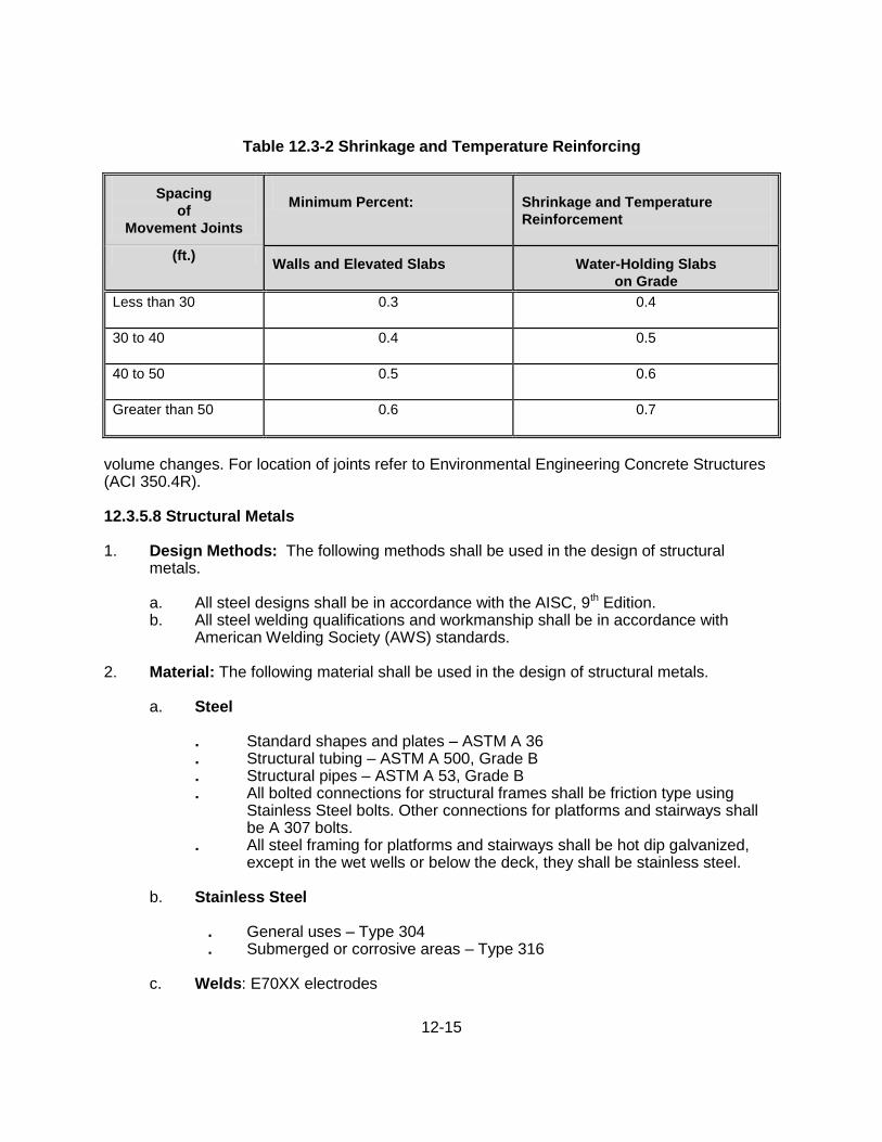
Shrinkage and temperature reinforcement to be provided depends upon the distance between the movement joints which will dissipate shrinkage and temperature stresses in the direction of the reinforcement. Use the minimum reinforcing in Table 12.3-2 in the design. Control and expansion joints are considered to be movement joints. Construction joints shall not be considered a movement joint.
c. Reinforcing steel spacing:
Use 3-, 6-, 9-, and 12-inch basis spaces for detailing. Avoid congested areas. Use 6- and 12-inch spacings where efficient design can be achieved. For special cases, especially where large quantities are involved, spacings of 4, 8, and 10 inches can be used to select the desirable bar size and achieve greater efficiency.
d. Construction, control, and expansion joints:
Each pump station should be designed and constructed with the use of control joints, construction joints, and expansion joints properly located and detailed to accommodate curing shrinkage, thermal movement, and loadings from vertical and lateral forces. The design shall document shrinkage volume changes and compare these to expected temperature
12-15
Table 12.3-2 Shrinkage and Temperature Reinforcing
Spacing
of
Movement Joints
Minimum Percent:
Shrinkage and Temperature
Reinforcement
(ft.) Walls and Elevated Slabs Water-Holding Slabs
on Grade
Less than 30 0.3 0.4
30 to 40 0.4 0.5
40 to 50 0.5 0.6
Greater than 50 0.6 0.7
volume changes. For location of joints refer to Environmental Engineering Concrete Structures (ACI 350.4R).
12.3.5.8 Structural Metals 1. Design Methods: The following methods shall be used in the design of structural
metals. a. All steel designs shall be in accordance with the AISC, 9th Edition. b. All steel welding qualifications and workmanship shall be in accordance with
American Welding Society (AWS) standards.
2. Material: The following material shall be used in the design of structural metals.
a. Steel . Standard shapes and plates – ASTM A 36 . Structural tubing – ASTM A 500, Grade B . Structural pipes – ASTM A 53, Grade B . All bolted connections for structural frames shall be friction type using
Stainless Steel bolts. Other connections for platforms and stairways shall be A 307 bolts.
. All steel framing for platforms and stairways shall be hot dip galvanized, except in the wet wells or below the deck, they shall be stainless steel.
b. Stainless Steel
. General uses – Type 304 . Submerged or corrosive areas – Type 316
c. Welds: E70XX electrodes

12-16
d. Structural Aluminum: Allow 6061-T6
e. Grating and Cover Plate: Unless noted otherwise, all gratings and cover plates shall be galvanized steel, hot dipped after fabrication. Fiberglass grating shall be used in areas subject to chemicals but shall only be allowed in areas where loads are limited to pedestrians loads.
f. Handrails: Unless noted otherwise, all handrails shall be galvanized, hot dipped
after fabrication, except below the deck they shall be stainless steel.

12-17
12.3.6 Electrical/Instrumentation Design 12.3.6.1 Applicable Codes and Standards: Electrical systems to be designed in strict compliance with the applicable portions of the following codes and standards:
1. National Electrical Code (NEC) 2. National Electrical Manufacturers Association (NEMA) Standards 3. American National Standards Institute (ANSI) Standards 4. Joint Industrial Council (JIC) Standards 5. Instrument Society for Measurement and Control 6. Institute of Electrical and Electronic Engineers (IEEE) Standards 7. Insulated Cable Engineers (ICEA) Standards 8. Occupational Safety and Health Administration Standards (OSHA) Standards 9. National Fire Protection Association (NFPA) Standards 10. All applicable state and local codes The electrical systems for all projects are to be heavy-duty industrial type with design emphasis placed on safety, reliability, maintainability, and economics. 12.3.6.2 Electrical Documents: Electrical specifications are to include the following sections: 16010 Electrical Work 16012 Seismic Restraint for Electrical Equipment 16013 Short Circuit, Protective Device study, Coord. and Flash Analysis 16110 Raceway Systems 16120 Low Voltage Wire and Cable 16395 Low Voltage Automatic Transfer Switchgear 16430 Low Voltage Main Switchgear 16480 Low Voltage Motor Control Center 16482 Soft Starter 16483 Variable Frequency Drives 16530 Lighting 16620 Standby Power System 16921 RTU/PLC System 16922 Miscellaneous Equipment 16950 Operational Testing
12.3.6.3 Electrical Drawings: Electrical drawings shall be numbered ―E-1" to ―E-n‖ and shall adhere to all standard design practices, and incorporate a logical and consistent methodology. The ―E‖ drawings shall include the following sheets if applicable:
1. E-1. Symbols and abbreviations:
These drawings are to depict the more commonly used electrical symbols and abbreviations. Those symbols or abbreviations used only occasionally are to be defined on the drawing they appear on in the "notes" column.
Abbreviations shall be listed in alphabetical order and make use of industry standards whenever possible.
12-18
Symbols used shall be industry standard whenever possible and shall include: Process Switches, Operator Switches, Relay Devices, Front Panel Devices, Components, Protective and Miscellaneous devices, Wiring Connections, and Plan Symbols. In cases where symbols incorporate unique symbology, an example are to be described next to the symbol. All symbols or abbreviations used on any drawing shall be listed on the Electrical Symbols & Abbreviations drawing in a logical order to facilitate ease of use and understanding of the design.
2. E-2. One-line diagram:
One-line drawings are to show a single-line of the power distribution. The drawings show a representation of the physical layout and location of the power distribution system. These drawings show how power is distributed from the utility source to the motor loads via switchboards and MCCs.
Breaker identification, size, type and locations shall be shown on the one-line drawings. The one-line drawings are site specific and may include the following:
a. Complete 480 V distribution system b. Standby Power System rating c Load Bank connection plugs d. Power Transformers e. 480 V Feeders f. Automatic Transfer Switch g. All motor loads connected to all MCCs h. Load names & Equipment Numbers i. Load Horsepower ratings and full load amps (FLA) j. NEMA rated starters k. Power factor correction capacitors connected to each MCC l. Breaker size, type and number of poles m. Location of each distribution switchboard and MCC n. Feeders down to the 120 V secondary of panel board transformers o. Load Calculations for Utility Service
p. Short or Fault Current Available
Load calculations to be made to calculate the total load on the Utility service. The total load is to include the motor, panel board, lighting and receptacle loads. Load calculations are used to determine the adequacy of the new meter service. Load calculations are to include all NEC load calculation factors.
Reduced voltage starting methods to be used for pumps greater than 100 HP, and for pumps 100 HP or less, if required by the power utility company.
One-line, load calculations, service request form, and drawings showing meter location, utility transformer location, primary & secondary power conduit routing & size, service wire (type, size & number) and embedded ground location are to be submitted to the governing power utility at the 90% design stage or earlier
12-19
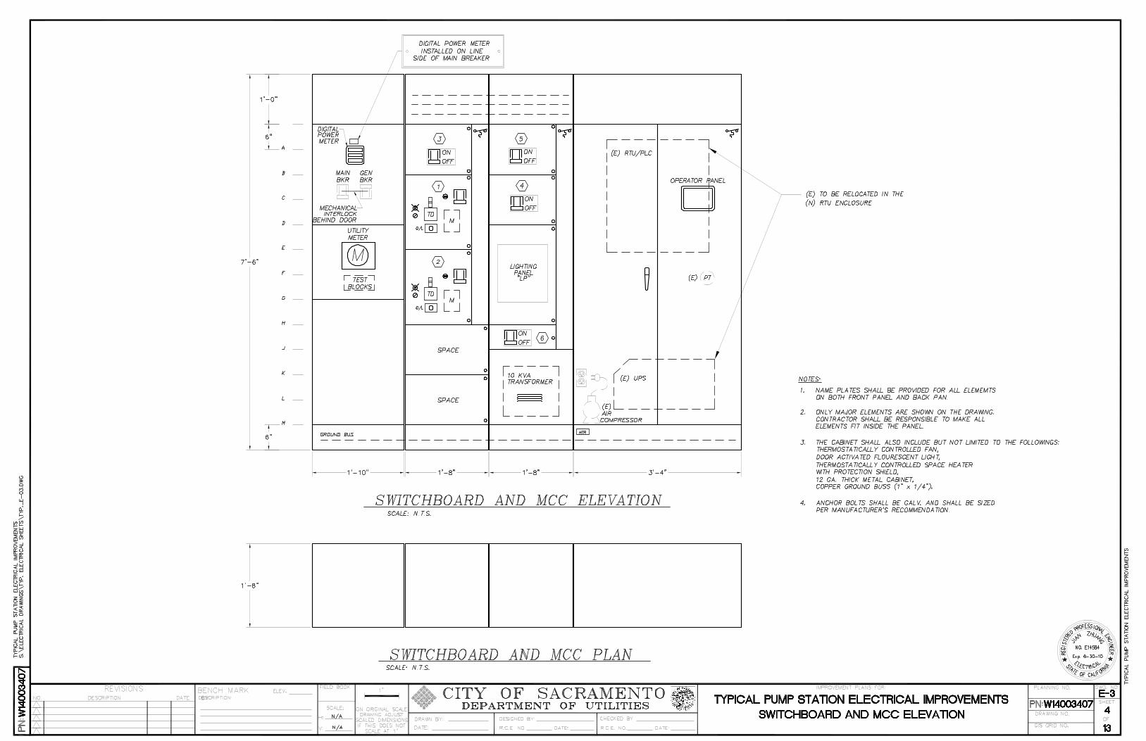
3. E-3. Elevation diagram:
Each elevation diagram shows the appearance and layout of specific panels along with drawing equipment location and detail notes necessary to convey proper design and construction. The elevation diagrams are to show the following:
a. Panel name and number b. Designate each panel section within a line-up c. Width, height, and depth dimensions for each section in inches d. All panel devices shown in their respective locations including but not limited to: . Equipment mounting details . Utility meters . Operator switches, push buttons, lights and display screens
. Circuit breakers and Panel boards . Fans and grills . Equipment and miscellaneous nameplates . Alphabetical vertical coordinates . Mounting pads . Alphabetical vertical coordinates . Convenience receptacles . Heights of elapsed time meter(42-68")
Magnified areas with separate detail to the side of magnified area where further detail is necessary
Miscellaneous construction notes:
MCC cubicle layout is to be provided with each equipment controls. The MCC cubicle layout is to show what is mounted to the face of the MCC cubicle. The cubicle layout are to physically show where the breaker, indicating lights, elapsed time meter, push-buttons, and selector switch are to be located. Show the engraved description for all nameplates.
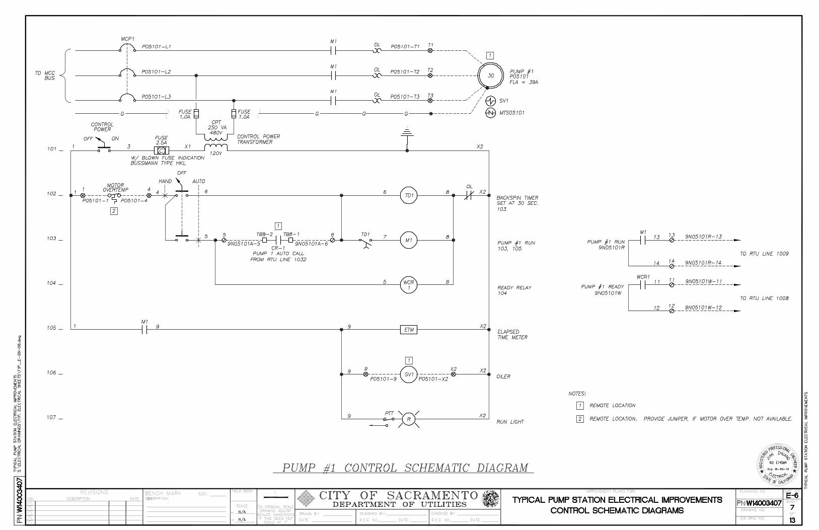
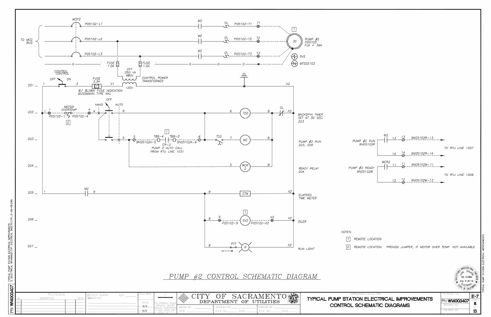
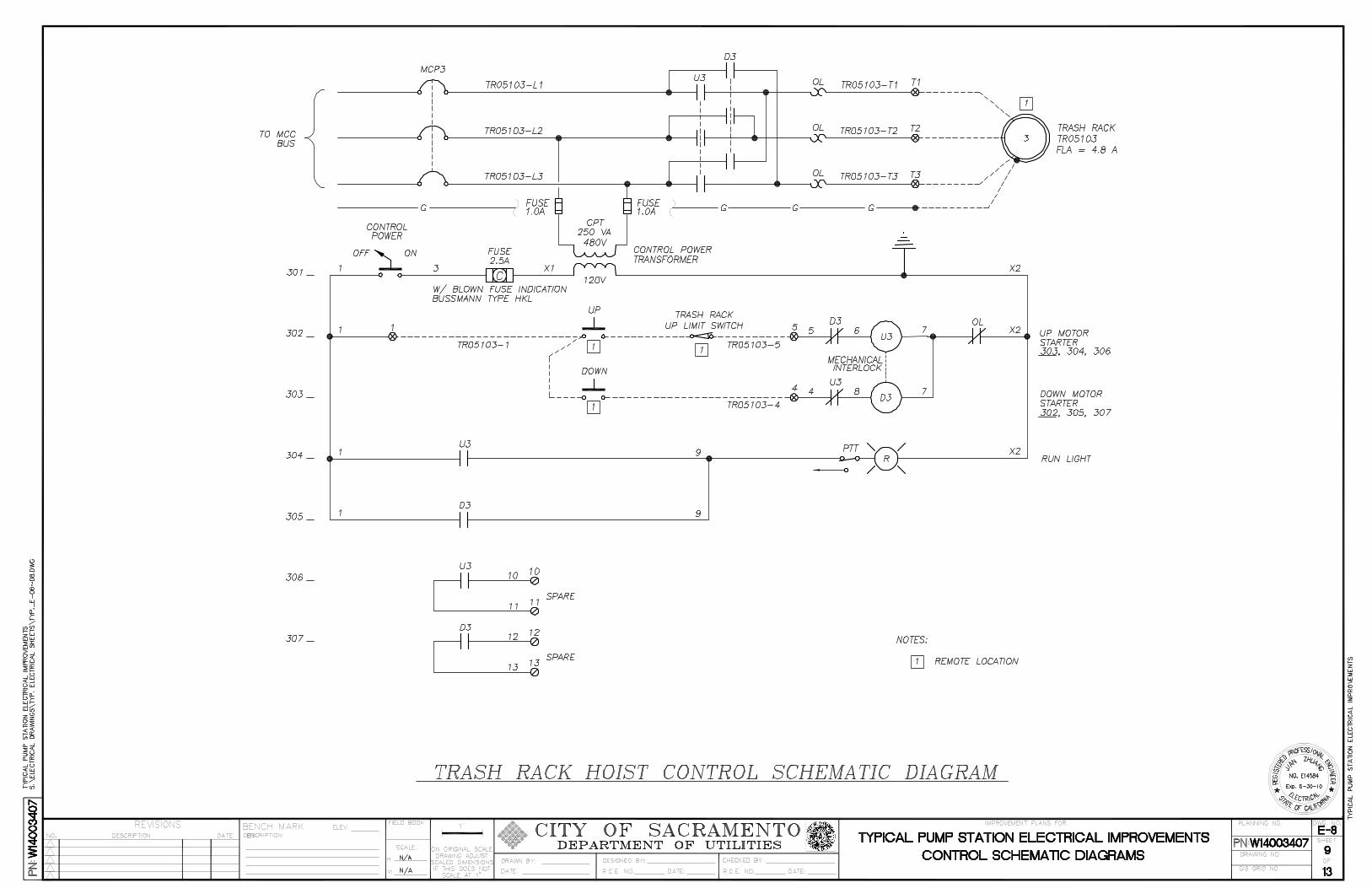
4. E-4. Elementary diagram:
Each elementary diagram shows how the equipment is to be controlled. The diagram is to be grouped to show the electrical wiring connections that are common to a group of equipment. The elementary diagram is to be drawing in ladder logic format and show the following:
a. Equipment name & number. b. Cross reference line numbers beginning at the top of the diagram and ending at
the bottom of the diagram. Reference numbering between coil and contact locations.
c. Line notes & comments to the right of each line d. Supply voltage e. Wire numbers and terminal numbers f. Control power transformer size and fuses g. Hand-Off-Auto (HOA) switch connection h. Outputs to PLC
12-20
i. Inputs from PLC j. Relays k. Indicating lights l. Ammeter and ammeter switch m. Elapsed Time Meter (ETM)
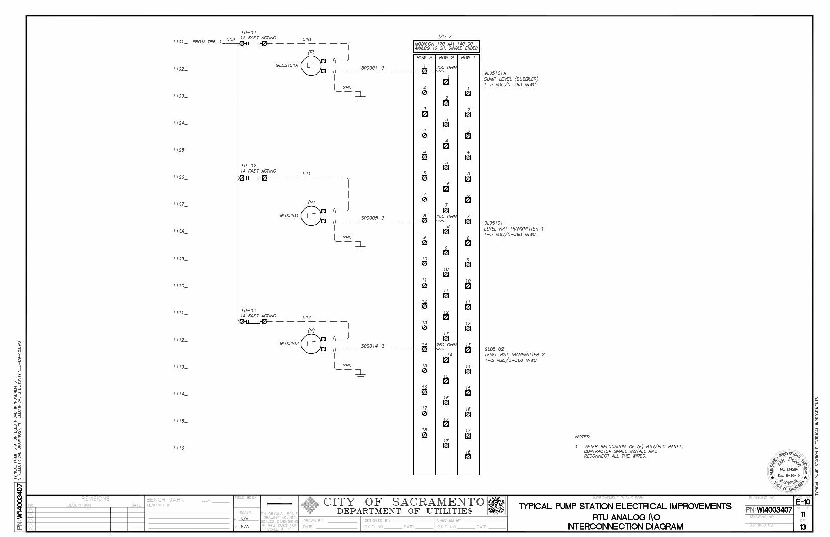
5. E-5. Instrumentation schematic diagrams:
The Telemetry I/O Schematic drawings show how instruments and devices are connected to the Control Panel. The schematics shall show the following detail:
a. Terminal block connections from the instrument to the specific control panel terminals b. Equipment description, ranges and tag names c. Type of signal (4-20 mA, 0-5V, discrete input or output, etc.)
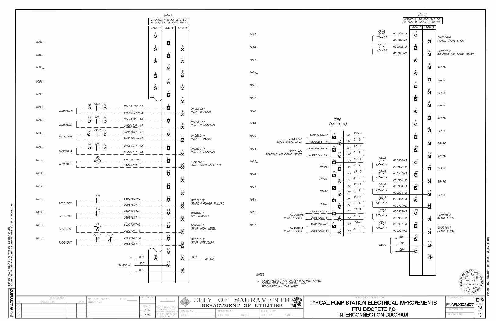
6. E-6. RTU interconnection diagram:
The RTU interconnection diagram shows all digital and analog I/O interfaces with the RTU.
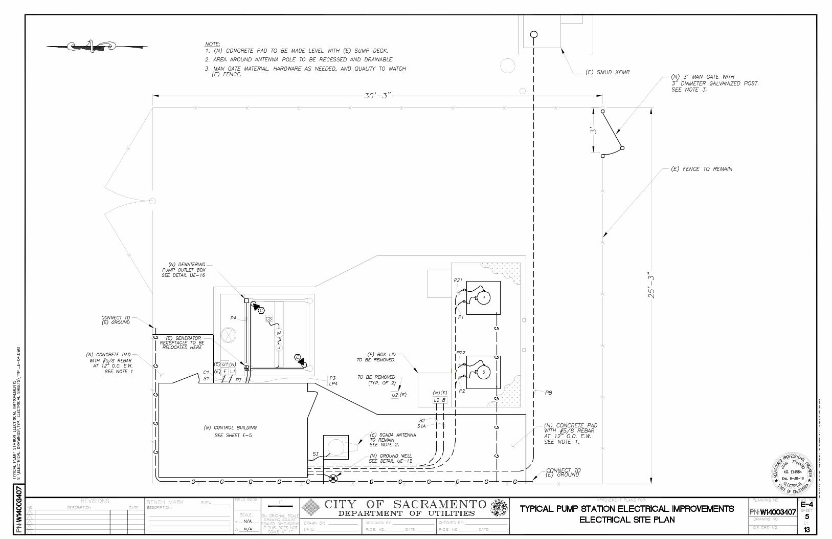
7. E-7. Electrical site plan-power & lighting conduit layout:
This drawing is to depict the routing of underground raceways, locations of major electrical equipment, and interconnections grounding and power systems. Utility Main Service ground bond and grounding system are to meet NEC and City of Sacramento codes. Building frames, generator frame, motor frames, metal pipes, fence, antenna, metal bollard and posts and any other major metal surfaces are to be tied to the main service ground with bar copper wires. Fuel tank is to be grounded per manufacturers instructions. The drawing shall show: a. Utility Services including transformer pad, primary and secondary conduits b. Vaults & pull-boxes c. Conduits with numbers and physical path of installation d. Site area lights e. Duct Banks f. Ground Wires
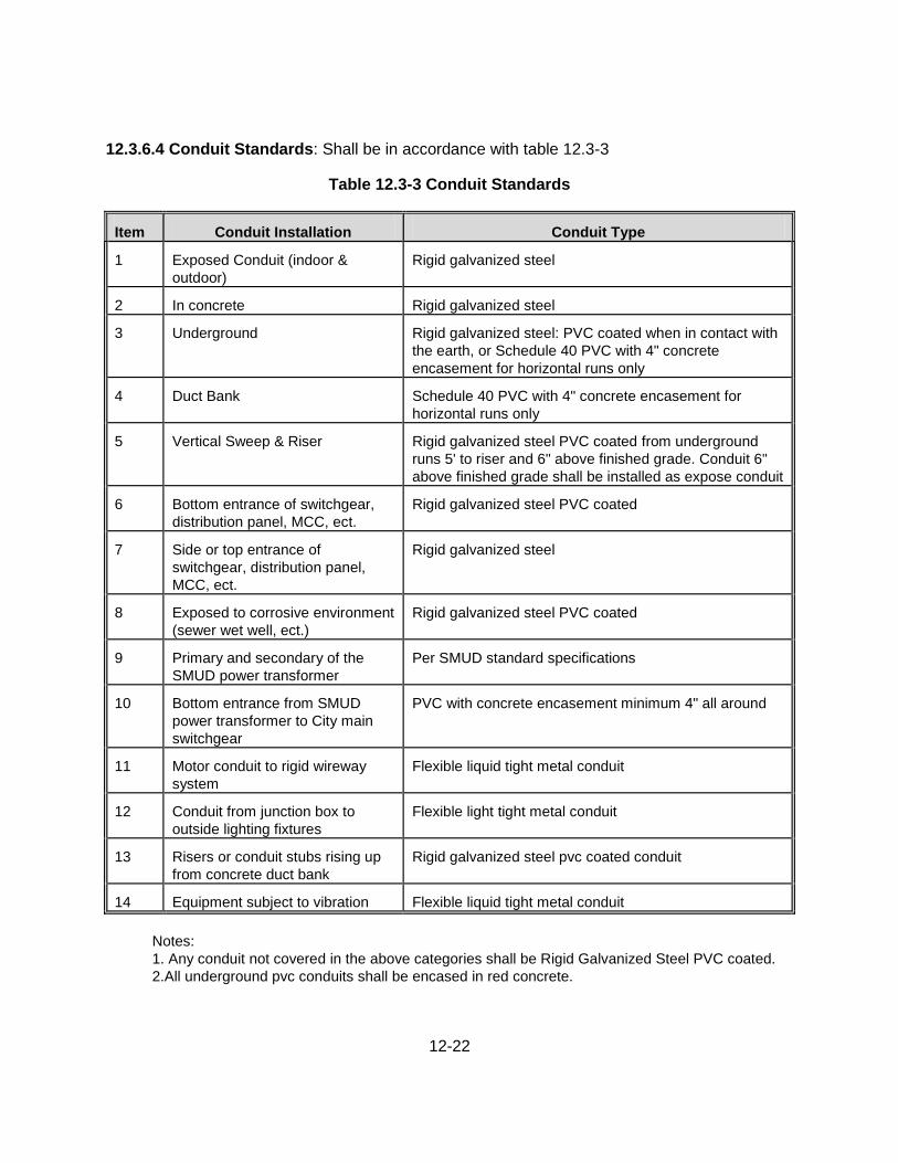
The standards listed in Table 12.3-3 shall apply to conduits.
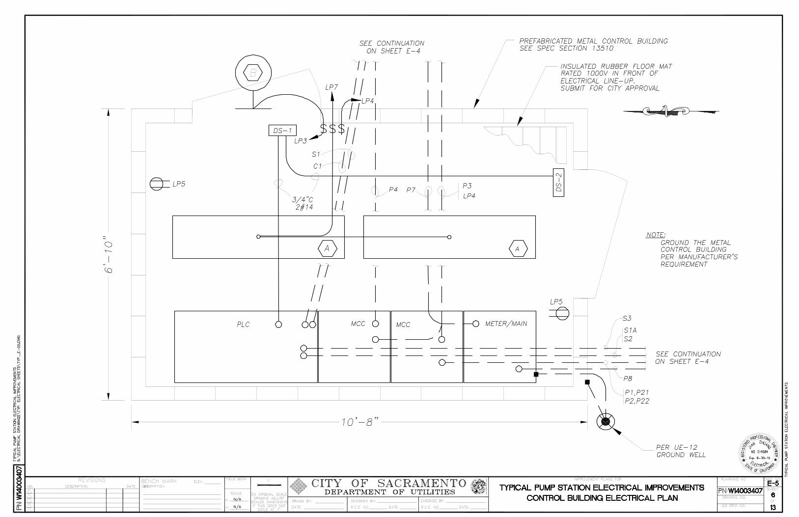
8. E-8. Building Electrical Plan - power & lighting/receptacle layout:
These drawings are to depict the location each power panel within the building and each lighting fixture, switch, receptacle, and battery pack emergency light. Fixtures are to be identified with letters within a fixture schedule by type, lamps, watts, manufacturer, mounting and notes. Mounting heights are to be specified.
12-21
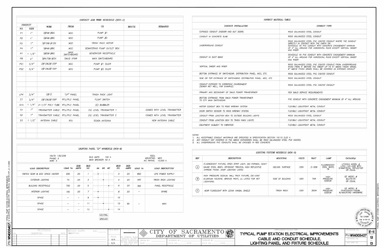
9. E-9. Conduit and Wire, Lighting Panal & Fixtures Schedules:
This drawing shall contain: a. Conduit and wire schedule b. Conduit material list c. Lighting fixture schedule d. Lighting panal and panal board layout including:
. Volts, Phase, & Wire . Bus Amps & Main Breaker Size . Enclosure & AIC Ratings . Breaker Descriptions, Loads, Amps, and Numbers . Left & Right side Amps & kVA calculations
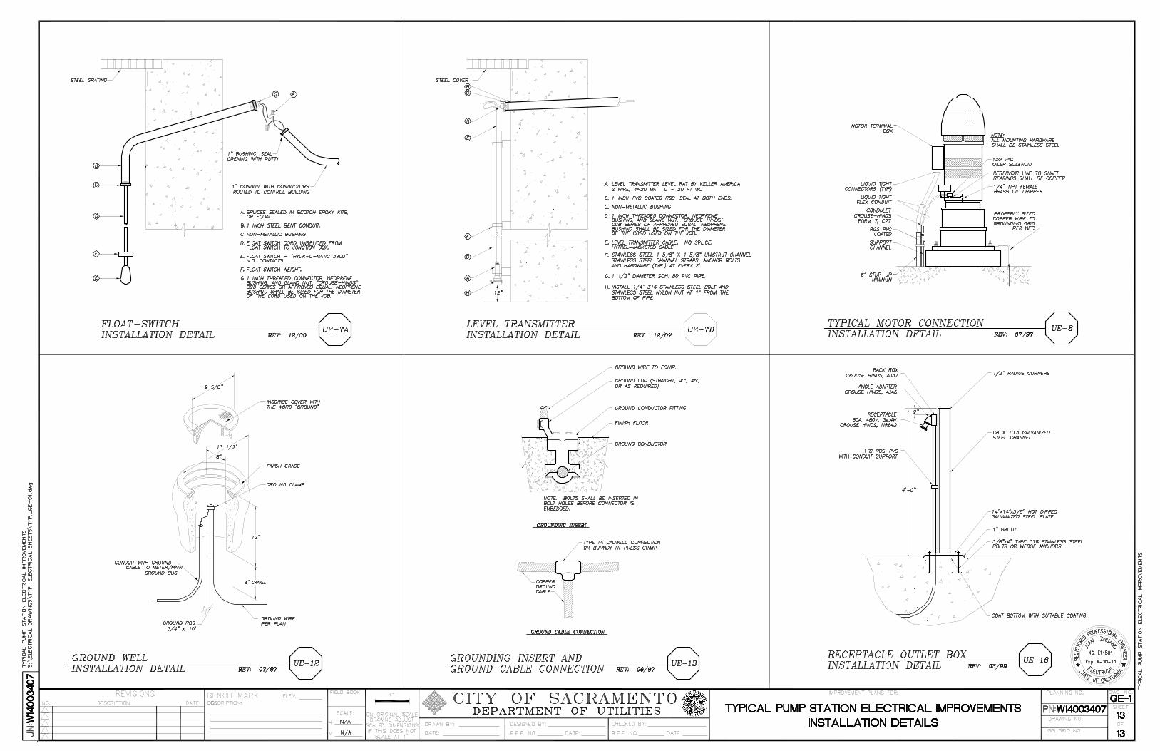
10. GE 1-4. Miscellaneous Electrical Construction Details:
Several drawings are used to show typical details that are required on all projects. In addition, these drawings are used to depict details that are specific for this project. Miscellaneous construction detail shall include: a. Pump motor connections b. Area lighting details c. Antenna pole details d. Duct bank details e. Access Box details f. Fence and Gate detailsg h. Sensor installation details i. Operator switch supports and mounting details
j. Power Outlet (480v) k. Encasement detail l. Generator hookup
12-22
12.3.6.4 Conduit Standards: Shall be in accordance with table 12.3-3
Table 12.3-3 Conduit Standards
Item Conduit Installation Conduit Type
1 Exposed Conduit (indoor &
outdoor)
Rigid galvanized steel
2 In concrete Rigid galvanized steel
3 Underground Rigid galvanized steel: PVC coated when in contact with
the earth, or Schedule 40 PVC with 4" concrete
encasement for horizontal runs only
4 Duct Bank Schedule 40 PVC with 4" concrete encasement for
horizontal runs only
5 Vertical Sweep & Riser Rigid galvanized steel PVC coated from underground
runs 5' to riser and 6" above finished grade. Conduit 6"
above finished grade shall be installed as expose conduit
6 Bottom entrance of switchgear,
distribution panel, MCC, ect.
Rigid galvanized steel PVC coated
7 Side or top entrance of
switchgear, distribution panel,
MCC, ect.
Rigid galvanized steel
8 Exposed to corrosive environment
(sewer wet well, ect.)
Rigid galvanized steel PVC coated
9 Primary and secondary of the
SMUD power transformer
Per SMUD standard specifications
10 Bottom entrance from SMUD
power transformer to City main
switchgear
PVC with concrete encasement minimum 4" all around
11 Motor conduit to rigid wireway
system
Flexible liquid tight metal conduit
12 Conduit from junction box to
outside lighting fixtures
Flexible light tight metal conduit
13 Risers or conduit stubs rising up
from concrete duct bank
Rigid galvanized steel pvc coated conduit
14 Equipment subject to vibration Flexible liquid tight metal conduit
Notes:
1. Any conduit not covered in the above categories shall be Rigid Galvanized Steel PVC coated.
2.All underground pvc conduits shall be encased in red concrete.
12-23
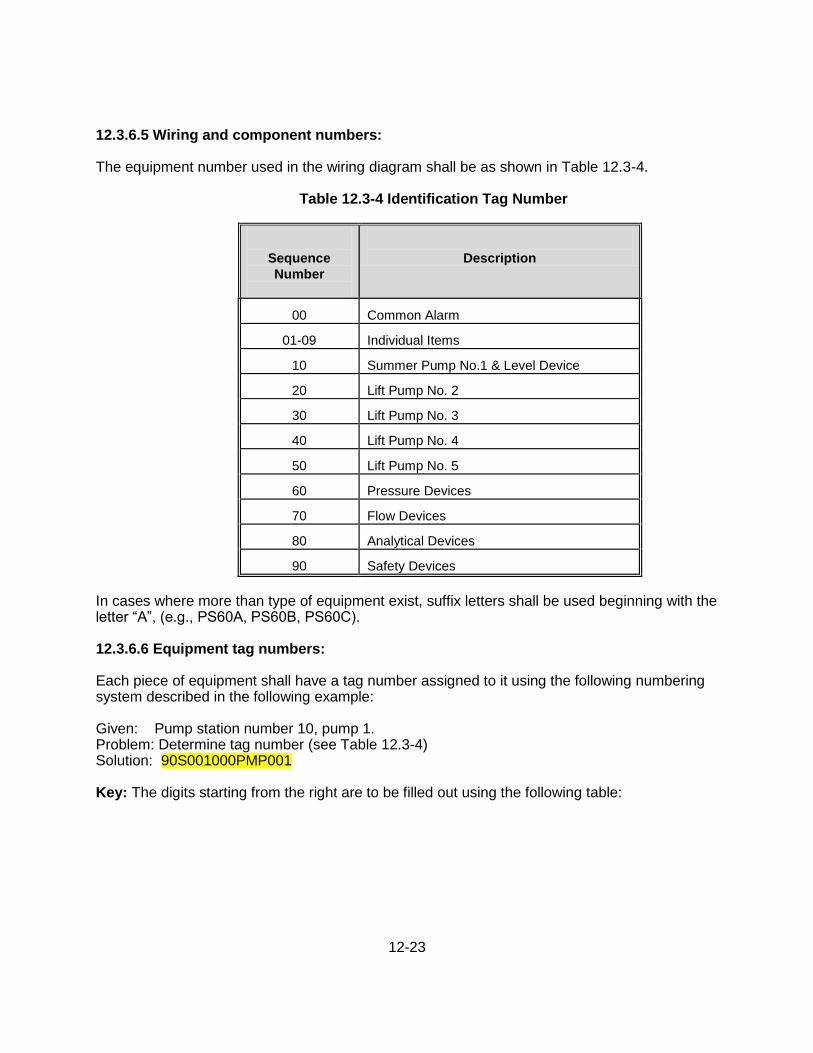
12.3.6.5 Wiring and component numbers: The equipment number used in the wiring diagram shall be as shown in Table 12.3-4.
Table 12.3-4 Identification Tag Number
Sequence
Number
Description
00 Common Alarm
01-09 Individual Items
10 Summer Pump No.1 & Level Device
20 Lift Pump No. 2
30 Lift Pump No. 3
40 Lift Pump No. 4
50 Lift Pump No. 5
60 Pressure Devices
70 Flow Devices
80 Analytical Devices
90 Safety Devices
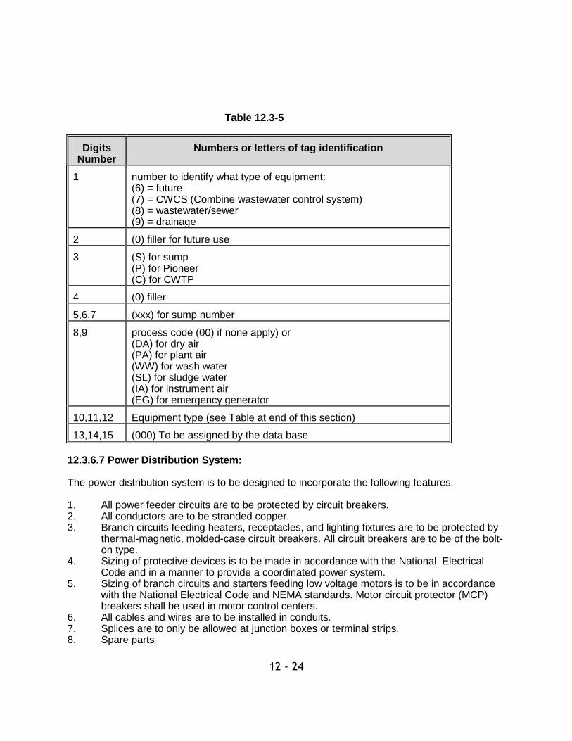
In cases where more than type of equipment exist, suffix letters shall be used beginning with the letter ―A‖, (e.g., PS60A, PS60B, PS60C). 12.3.6.6 Equipment tag numbers: Each piece of equipment shall have a tag number assigned to it using the following numbering system described in the following example: Given: Pump station number 10, pump 1. Problem: Determine tag number (see Table 12.3-4) Solution: 90S001000PMP001 Key: The digits starting from the right are to be filled out using the following table:
12 - 24
Table 12.3-5
Digits Number
Numbers or letters of tag identification
1 number to identify what type of equipment: (6) = future (7) = CWCS (Combine wastewater control system) (8) = wastewater/sewer (9) = drainage
2 (0) filler for future use
3 (S) for sump (P) for Pioneer (C) for CWTP
4 (0) filler
5,6,7 (xxx) for sump number
8,9 process code (00) if none apply) or (DA) for dry air (PA) for plant air (WW) for wash water (SL) for sludge water (IA) for instrument air (EG) for emergency generator
10,11,12 Equipment type (see Table at end of this section)
13,14,15 (000) To be assigned by the data base
12.3.6.7 Power Distribution System: The power distribution system is to be designed to incorporate the following features: 1. All power feeder circuits are to be protected by circuit breakers. 2. All conductors are to be stranded copper. 3. Branch circuits feeding heaters, receptacles, and lighting fixtures are to be protected by thermal-magnetic, molded-case circuit breakers. All circuit breakers are to be of the bolt- on type. 4. Sizing of protective devices is to be made in accordance with the National Electrical Code and in a manner to provide a coordinated power system. 5. Sizing of branch circuits and starters feeding low voltage motors is to be in accordance with the National Electrical Code and NEMA standards. Motor circuit protector (MCP) breakers shall be used in motor control centers. 6. All cables and wires are to be installed in conduits. 7. Splices are to only be allowed at junction boxes or terminal strips. 8. Spare parts
12-25
9. All components to be NEMA rated. 10. Voltage separation is to be accomplished in the following manner: 11. High voltage power conductors are to be installed in separate duct banks and are to be
kept separate from all other cables. 12. 480V power and 120V control conductors can be installed in common raceway, derating
conductor sizes based on conduit fill. 13. 24V DC signal conductors are to be installed in separate raceways. 14. Communications conductors are to be installed in separate raceways. 15. Minimum size wire size shall be Number 12 for power conductor and Number 14 for
control. 12.3.6.8 Standby Power System The standby power system is to be designed to incorporate the features as follows. 1. Automatic Transfer Switch: NEMA ICS 2, automatic transfer switch suitable for use as
service equipment. 2. Indicating Lights: Normal Source Available, Alternative Source Available, Powered from
Normal Source, Powered from Alternative Source. 3. Test Switch: to simulate failure of normal source. 4. Manual Return to Normal Control: 2 position AUTO-MANUAL selector switch and
initiate push button to allow manual transfer from alternate to normal source. 5. Normal Source Monitor: monitors normal source voltage and frequency; initiate transfer
when voltage drops below 85 percent of frequency varies more than 3 percent from rated nominal value.
6. Alternate Source Monitor: monitors alternate source voltage and frequency; inhibit
transfer when voltage is below 85 percent of frequency varies more than 3 percent from rated nominal value.
7. In-Phase Monitor: Controls transfer/retransfer operation between live sources when
sources are approaching zero phase angle. 8. Generator:
a. NFPA 110, to provide source of power for Standby applications all in an indoor housing with sub-base fuel tank and NFPA 31 for install guidelines.
b. System Capacity: Sized to start the pumps needed to discharge the design
capacity of the pump station, in any order, with a maximum voltage dip of 25 percent.
c. Fuel Tank: Sub-base fuel tank unit flexible fuel line connections, fuel gauge & fuel,
level transmitter producing 4-20 mA signal, and low fuel level alarm switch. Fuel tank to be double walled construction and structurally designed to provide the base for the mounting of the engine-generator set.
12 - 26
The tank shall be sized to provide a minimum 24 hours of operation at full load. The tank shall include an additional 2" of freeboard for liquid expansion and 3" of additional depth for solids build up in the bottom of the tank. Level sencer shall be approved purification company.
d. Exhaust Silencer: Critical grade type silencer, with muffler companion flanges and
flexible stainless steel exhaust fitting.
e. Generator Control Panel: NEMA 250 Type, generator unit mounted. Instruments shall be accurate within 2 percent. Provide Load Bank plugs for City to plug in their portable load bank for testing. No breaker at load bank terminals.
f. Communications Capability: Include all hardware and software needed for
communications with electronic control units such as ELM’s and fuel management systems.
g. Air Quality Permit: The generator shall meet the air quality requirements and be
permitted for emergency power generation per the Sacramento Metropolitan Air Quality Management Division
12.3.6.9 Control: Motor control circuits are to incorporate the following: 1. Located in drawout buckets of Motor Control Center (MCC).
2. A manual station is to be located at the MCC cubicle for each motor. This station is to allow the Operator to start/stop the motor for maintenance, testing, and serve as a annual back-up in the event the automatic control system is inoperative. 3. Hand-Off Auto (HOA) selector switches are to be provided for each pump. Selector Switch ―Automatic‖ position enables for auto control by the PLC. ―Hand‖ selector switch position allows Operator to run equipment independent of the level controls. ―Off‖ selector switch position allows Operator to stop equipment independent of the level controls. 4. The circuit breaker located at the MCC is to be equipped with a pad-lockable positive lock-out for the individual mechanical equipment. 5. Each motor starter cubicle is to be provisioned with a Motor Circuit Protector (MCP) circuit breaker and a manual push button to reset a contactor thermal overload trip. 6. An ammeter is to be incorporated into the MCC cubicles to monitor each of the 3 motor phases. An Amps 3-way selector (A-B-C) switch is to be mounted below the display to allow the operator to monitor any one of the three phases. 7. Door mounted red run-status indicating lamp and neon blown control circuit fuse. 8. Interlocking, sequencing and timing functions are to be provided by a programmable logic controller (PLC) located at the Control Panel. 9. Control voltage to be 120V derived from a stepdown control power transformer located in each bucket.
10. All equipment to be NEMA rated components.
12-27
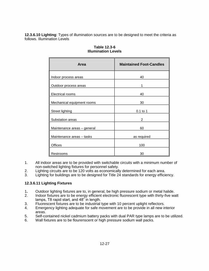
12.3.6.10 Lighting: Types of illumination sources are to be designed to meet the criteria as follows. Illumination Levels
Table 12.3-6
Illumination Levels
Area
Maintained Foot-Candles
Indoor process areas
40
Outdoor process areas
1
Electrical rooms
40
Mechanical equipment rooms
30
Street lighting
0.1 to 1
Substation areas
2
Maintenance areas – general
60
Maintenance areas – tasks
as required
Offices
100
Restrooms
30
1. All indoor areas are to be provided with switchable circuits with a minimum number of non-switched lighting fixtures for personnel safety. 2. Lighting circuits are to be 120 volts as economically determined for each area. 3. Lighting for buildings are to be designed for Title 24 standards for energy efficiency. 12.3.6.11 Lighting Fixtures 1. Outdoor lighting fixtures are to, in general, be high pressure sodium or metal halide. 2. Indoor fixtures are to be energy efficient electronic fluorescent type with thirty-five watt lamps, T8 rapid start, and 48‖ in length. 3. Fluorescent fixtures are to be industrial type with 10 percent uplight reflectors. 4. Emergency lighting adequate for safe movement are to be provide in all new interior areas. 5. Self-contained nickel cadmium battery packs with dual PAR type lamps are to be utilized. 6. Wall fixtures are to be flourenscent or high pressure sodium wall packs.
12-28
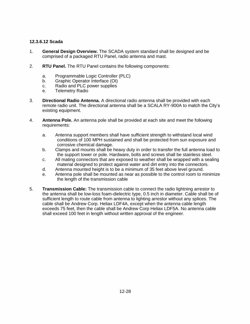
12.3.6.12 Scada 1. General Design Overview. The SCADA system standard shall be designed and be
comprised of a packaged RTU Panel, radio antenna and mast. 2. RTU Panel. The RTU Panel contains the following components:
a. Programmable Logic Controller (PLC) b. Graphic Operator Interface (OI) c. Radio and PLC power supplies e. Telemetry Radio
3. Directional Radio Antenna. A directional radio antenna shall be provided with each
remote radio unit. The directional antenna shall be a SCALA RY-900A to match the City’s existing equipment.
4. Antenna Pole. An antenna pole shall be provided at each site and meet the following
requirements:
a. Antenna support members shall have sufficient strength to withstand local wind conditions of 100 MPH sustained and shall be protected from sun exposure and corrosive chemical damage.
b. Clamps and mounts shall be heavy duty in order to transfer the full antenna load to the support tower or pole. Hardware, bolts and screws shall be stainless steel.
c. All mating connectors that are exposed to weather shall be wrapped with a sealing material designed to protect against water and dirt entry into the connectors.
d. Antenna mounted height is to be a minimum of 35 feet above level ground. e. Antenna pole shall be mounted as near as possible to the control room to minimize
the length of the transmission cable 5. Transmission Cable: The transmission cable to connect the radio lightning arrestor to
the antenna shall be low-loss foam-dielectric type, 0.5 inch in diameter. Cable shall be of sufficient length to route cable from antenna to lighting arrestor without any splices. The cable shall be Andrew Corp. Heliax LDF4A, except when the antenna cable length exceeds 75 feet, then the cable shall be Andrew Corp Heliax LDF5A. No antenna cable shall exceed 100 feet in length without written approval of the engineer.
12-29
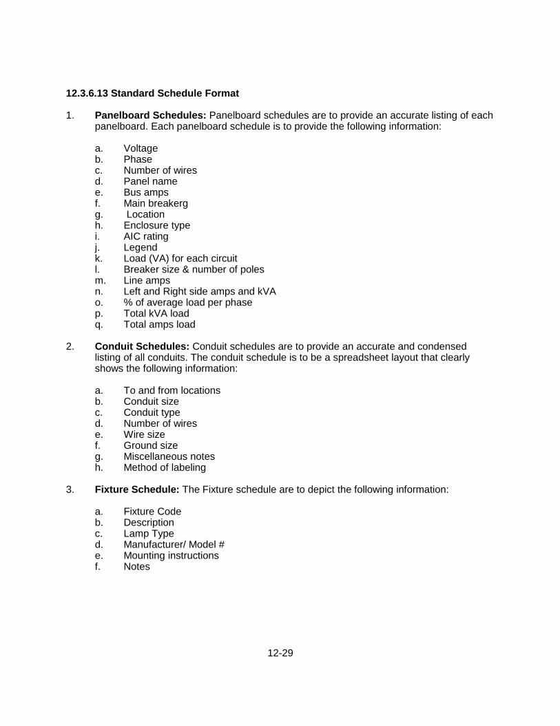
12.3.6.13 Standard Schedule Format 1. Panelboard Schedules: Panelboard schedules are to provide an accurate listing of each
panelboard. Each panelboard schedule is to provide the following information:
a. Voltage b. Phase c. Number of wires d. Panel name e. Bus amps f. Main breakerg g. Location h. Enclosure type i. AIC rating j. Legend k. Load (VA) for each circuit l. Breaker size & number of poles m. Line amps n. Left and Right side amps and kVA o. % of average load per phase p. Total kVA load q. Total amps load
2. Conduit Schedules: Conduit schedules are to provide an accurate and condensed
listing of all conduits. The conduit schedule is to be a spreadsheet layout that clearly shows the following information:
a. To and from locations b. Conduit size c. Conduit type d. Number of wires e. Wire size f. Ground size g. Miscellaneous notes h. Method of labeling
3. Fixture Schedule: The Fixture schedule are to depict the following information:
a. Fixture Code b. Description c. Lamp Type d. Manufacturer/ Model # e. Mounting instructions f. Notes
12-30
12.3.6.14 Startup and Operation Requirement 1. Start-Up Testing
Each item of mechanical, electrical and instrumentation equipment shall be tested before any facility is put into operation. Testing shall conform to the requirements of Section 16950 of the Standard Specifications (Section 9).
2. Operation and Maintenance Information:
An operations and maintenance manual shall be submitted for each maintainable piece of equipment, equipment assembly or subassembly. The manual shall conform to the requirements of Section 01330 of the Standard Specifications.
12.3.6.15 Record Drawings The City shall receive record drawings showing the as built locations and layout of all mechanical, electrical, and instrumentation equipment; piping and conduits; structures; and other facilities as required in Section 01330, paragraph 3.03, of the standard specifications. Record drawings shall be submitted in AutoCAD format and as inked drawings (electrostatic or ink plotter) on Mylar.
12-31
12.4 PUMP STATION MASTER SPECIAL PROVISIONS The complete drainage pump station Master Special Provisions (Master Specs) in CSI format, developed by DOU, shall be the basis for the design and construction of all pump stations which are to be owned, operated, and/or maintained by the City of Sacramento (City pump stations). They shall be modified appropriately to address project specific applications by the EOR and modifications shall be approved by the Director. Approved, modified Master Specs shall be included in the bid documents for the construction or rehabilitation of all City pump stations. Master Specs are updated regularly by DOU as needed and the current version is available in pdf format on the DOU web site at www.XXXXX.xxx and may also be obtained in electronic format by calling Andy Hunt at 916-808-1408.
12-32
12.5 SUBMITTAL REQUIREMENTS 12.5.1 GENERAL Professional engineers who are responsible for the design, construction, or rehabilitation of City pump stations shall meet with representatives of the Department of Utilities prior to beginning any pre-design or design work.
12.5.2 MEETING REQUIREMENTS On larger and more complex projects, the engineer shall meet with DOU staff, including appropriate Plant Services Division (Plants) staff, at minimum, at the project report, 10, 60, and 95 percent design stages. Smaller or less complex projects may require fewer meetings at the discretion of the City’s project manager. A minimum of three weeks prior to these meetings the engineer shall submit 4 copies of the required materials to the designated contact at DOU.
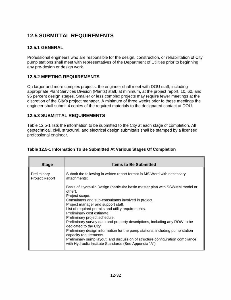
12.5.3 SUBMITTAL REQUIREMENTS Table 12.5-1 lists the information to be submitted to the City at each stage of completion. All geotechnical, civil, structural, and electrical design submittals shall be stamped by a licensed professional engineer. Table 12.5-1 Information To Be Submitted At Various Stages Of Completion
Stage
Items to Be Submitted
Preliminary Project Report
Submit the following in written report format in MS Word with necessary attachments: Basis of Hydraulic Design (particular basin master plan with SSWMM model or other). Project scope. Consultants and sub-consultants involved in project. Project manager and support staff. List of required permits and utility requirements. Preliminary cost estimate. Preliminary project schedule. Preliminary survey data and property descriptions, including any ROW to be dedicated to the City. Preliminary design information for the pump stations, including pump station capacity requirements. Preliminary sump layout, and discussion of structure configuration compliance with Hydraulic Institute Standards (See Appendix "A").
12-33
Stage
Items to Be Submitted
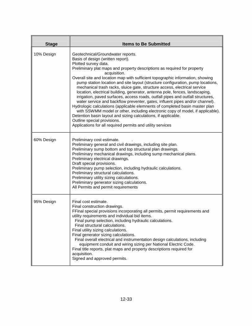
10% Design
Geotechnical/Groundwater reports. Basis of design (written report). Plotted survey data. Preliminary plat maps and property descriptions as required for property
acquisition. Overall site and location map with sufficient topographic information, showing
pump station location and site layout (structure configuration, pump locations, mechanical trash racks, sluice gate, structure access, electrical service location, electrical building, generator, antenna pole, fences, landscaping, irrigation, paved surfaces, access roads, outfall pipes and outfall structures, water service and backflow preventer, gates, influent pipes and/or channel).
Hydrologic calculations (applicable elemnents of completed basin master plan with SSWMM model or other, including electronic copy of model, if applicable).
Detention basin layout and sizing calculations, if applicable. Outline special provisions. Applications for all required permits and utility services
60% Design
Preliminary cost estimate. . Preliminary general and civil drawings, including site plan. Preliminary sump bottom and top structural plan drawings. Preliminary mechanical drawings, including sump mechanical plans. Preliminary electrical drawings. Draft special provisions. Preliminary pump selection, including hydraulic calculations. Preliminary structural calculations. Preliminary utility sizing calculations. Preliminary generator sizing calculations. All Permits and permit requirements
95% Design
Final cost estimate. Final construction drawings. FFinal special provisions incorporating all permits, permit requirements and utility requirements and individual bid items.
Final pump selection, including hydraulic calculations. Final structural calculations.
Final utility sizing calculations. Final generator sizing calculations.
Final overall electrical and instrumentation design calculations, including equipment conduit and wiring sizing per National Electric Code.
Final title reports, plat maps and property descriptions required for acquisition. Signed and approved permits.
12-34
Stage
Items to Be Submitted
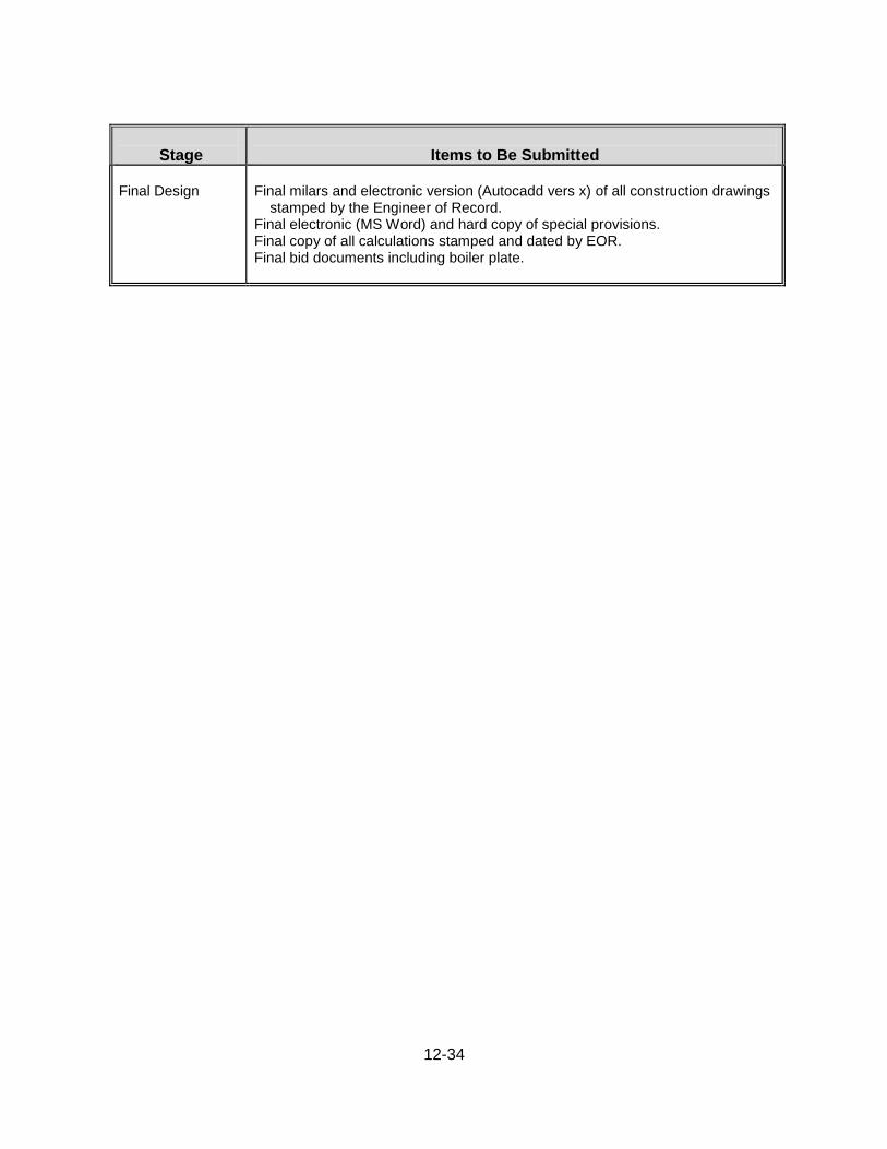
Final Design
Final milars and electronic version (Autocadd vers x) of all construction drawings
stamped by the Engineer of Record. Final electronic (MS Word) and hard copy of special provisions. Final copy of all calculations stamped and dated by EOR. Final bid documents including boiler plate.
12-35
12.6 AREA SPECIFIC REQUIREMENTS 12.6.1 NORTH NATOMAS Pump stations in North Natomas shall conform to all the requirements of Section 12 herein, as for an area with high ground water, except for additional criteria as follows: 1. Maximum Discharge:
The maximum discharge to RD 1000 canals shall not exceed 0.1 cfs per acre of contributing drainage area. The maximum discharge shall occur at the minimum pumping head to assure the maximum discharge does not exceed 0.1 cfs/acre.
2. Number of pumps:
A minimum of 4 peak flow pumps shall be required at each pumping plant. Each pump shall be capable of pumping 1/3 of the runoff from the drainage shed at the maximum design water level. The maximum design level shall be equal to the maximum water surface of the detention pond, minus the headloss into the sump assuming clean bar screens. The fourth pump shall act as backup.
3. Standby generators:
In North Natomas a stationary standby generator shall be required at each pump station regardless of the starting and running power requirements. The stationary generator shall be as described in 12.3.X.
4. Pump Calculations in Natomas:
In Natomas where three pumps are required, plus a redundant, the designer shall submit a copy of the spread sheet or other background calculations, along with graphs showing the pump curve vs. system curve for the follows conditions:
a. With three peak-flow pumps in operation, at both minimum and maximum static head.
(Minimum static head shall equal the minimum wet weather water level in the receiving water, minus the maximum design sump water level. Maximum static head shall equal the maximum wet weather water level in the receiving water, minus the design sump water level at which one of the three pumps will shut-off.)
b. With two peak-flow pumps in operation, at both minimum and maximum static head.
(Minimum static head shall equal the minimum wet weather water level in the receiving water, minus the maximum design sump water level at which only two pumps will operate. Maximum static head shall equal the maximum wet weather water level in the receiving water, minus the design sump water level at which two of the three peak-flow pumps will shut-off.)
c. With one peak-flow pump in operation, at both minimum and maximum static head. (Minimum static head shall equal the minimum wet weather water level in the receiving water, minus the maximum design sump water level at which only one pump will
12-36
operate. Maximum static head shall equal the maximum wet weather water level in the receiving water, minus the design sump water level at which all three peak-flow pumps will shut-off.)
d. The low-flow pump in operation, at both minimum and maximum static head. (Minimum
static head shall equal the minimum dry weather water level in the receiving water, minus the maximum design sump water level at which only the low-flow pump will operate. Maximum static head shall equal the maximum dry weather water level in the receiving water, minus the design sump water level at which the low-flow pump will shut-off.)
5. Pumps-Low Flow
Depending on basin configuration and operation, low flow pump(s) shall be installed to convey low flows and dry weather flows as part of the water quality component.
Low flow pumps may also be part of a pump-back system for water quality treatment and may also be installed to control local groundwater.
6. Operation
Pump operating levels shall be established to achieve the Detention and Water Quality objectives outlined in Section 11 and the following:
a. The first pump shall be turned on consistent with water quality storage requirements.
The off elevation shall not remove stored runoff at a faster rate or result in detention times less than allowed within the water quality criteria of Section 6.
b. The second pump shall be turned on based on engineering judgment, but at an elevation
at least one foot above the top of the water quality storage elevation. The off elevation shall be based on engineering judgment but shall not conflict with the water quality requirements.
c. The third pump shall be turned on at the maximum elevation of the 10-year storm.
Several durations shall be evaluated to determine the most critical duration and highest water surface elevation. The off elevation shall be based on engineering judgment.
d. The reason for the incremental pump operation is to provide a reasonable inflow pattern
into RD1000 facilities and not have pumped inflows greater than the storm severity.