stock & mto screw conveyor components · shaft seal compression type waste pack shaft seal...
TRANSCRIPT
H-2
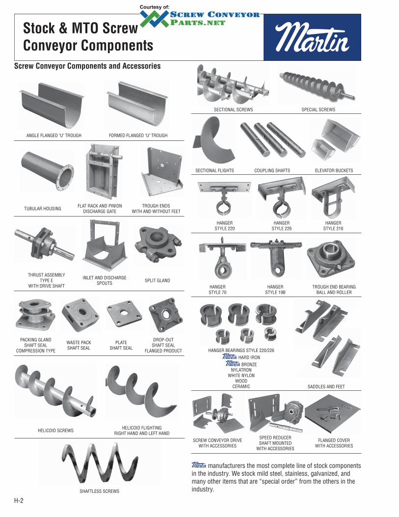
Stock & MTO Screw
Conveyor Components
Screw Conveyor Components and Accessories
ANGLE FLANGED "U" TROUGH
HELICOID SCREWS
PACKING GLANDSHAFT SEAL
COMPRESSION TYPE
WASTE PACKSHAFT SEAL
PLATESHAFT SEAL
DROP-OUTSHAFT SEAL
FLANGED PRODUCT
TUBULAR HOUSING FLAT RACK AND PINIONDISCHARGE GATE
TROUGH ENDSWITH AND WITHOUT FEET
SECTIONAL FLIGHTS COUPLING SHAFTS ELEVATOR BUCKETS
HANGERSTYLE 70
HANGERSTYLE 19B
TROUGH END BEARINGBALL AND ROLLER
SCREW CONVEYOR DRIVEWITH ACCESSORIES
SPEED REDUCERSHAFT MOUNTED
WITH ACCESSORIES
FLANGED COVERWITH ACCESSORIES
HANGERSTYLE 220
HANGERSTYLE 226
HANGERSTYLE 216
THRUST ASSEMBLYTYPE E
WITH DRIVE SHAFT
INLET AND DISCHARGE SPOUTS SPLIT GLAND
FORMED FLANGED "U" TROUGH
HELICOID FLIGHTING RIGHT HAND AND LEFT HAND
SECTIONAL SCREWS SPECIAL SCREWS
SHAFTLESS SCREWS
HANGER BEARINGS STYLE 220/226 HARD IRON
BRONZENYLATRON
WHITE NYLONWOOD
CERAMIC SADDLES AND FEET
manufacturers the most complete line of stock components in the industry. We stock mild steel, stainless, galvanized, and many other items that are “special order” from the others in the industry.
H-3
Engineering
ENGINEERING PAGE
INTRODUCTION TO ENGINEERING SECTION . . . . . . . . . . . . . . . . . . . . . . . . . . . . . . . . . . . . . . . . . . . . . . . . . . . . . . . . . H-3
SCREW CONVEYOR DESIGN PROCEDURE . . . . . . . . . . . . . . . . . . . . . . . . . . . . . . . . . . . . . . . . . . . . . . . . . . . . . . . . . . . H-4
MATERIAL CLASSIFICATION CODE CHART . . . . . . . . . . . . . . . . . . . . . . . . . . . . . . . . . . . . . . . . . . . . . . . . . . . . . . . . . . . H-5
MATERIAL CHARACTERISTICS TABLES . . . . . . . . . . . . . . . . . . . . . . . . . . . . . . . . . . . . . . . . . . . . . . . . . . . . . . . . . . . . . H-6
SELECTION OF CONVEYOR SIZE AND SPEED . . . . . . . . . . . . . . . . . . . . . . . . . . . . . . . . . . . . . . . . . . . . . . . . . . . . . . . H-16
CAPACITY FACTOR TABLES . . . . . . . . . . . . . . . . . . . . . . . . . . . . . . . . . . . . . . . . . . . . . . . . . . . . . . . . . . . . . . . . . . . . . . H-17
CAPACITY TABLE . . . . . . . . . . . . . . . . . . . . . . . . . . . . . . . . . . . . . . . . . . . . . . . . . . . . . . . . . . . . . . . . . . . . . . . . . . . . . . H-18
LUMP SIZE LIMITATIONS AND TABLE . . . . . . . . . . . . . . . . . . . . . . . . . . . . . . . . . . . . . . . . . . . . . . . . . . . . . . . . . . . . . . H-19
COMPONENT GROUP SELECTION . . . . . . . . . . . . . . . . . . . . . . . . . . . . . . . . . . . . . . . . . . . . . . . . . . . . . . . . . . . . . . . . . H-20
HANGER BEARING SELECTION . . . . . . . . . . . . . . . . . . . . . . . . . . . . . . . . . . . . . . . . . . . . . . . . . . . . . . . . . . . . . . . . . . . H-22
HORSEPOWER CALCULATION . . . . . . . . . . . . . . . . . . . . . . . . . . . . . . . . . . . . . . . . . . . . . . . . . . . . . . . . . . . . . . . . . . . H-23
TORSIONAL RATINGS OF CONVEYOR COMPONENTS . . . . . . . . . . . . . . . . . . . . . . . . . . . . . . . . . . . . . . . . . . . . . . . . . H-26
HORSEPOWER RATINGS OF CONVEYOR COMPONENTS . . . . . . . . . . . . . . . . . . . . . . . . . . . . . . . . . . . . . . . . . . . . . . . H-27
SCREW CONVEYOR END THRUST AND THERMAL EXPANSION . . . . . . . . . . . . . . . . . . . . . . . . . . . . . . . . . . . . . . . . . . H-28
SCREW CONVEYOR DEFLECTION . . . . . . . . . . . . . . . . . . . . . . . . . . . . . . . . . . . . . . . . . . . . . . . . . . . . . . . . . . . . . . . . H-29
INCLINED AND VERTICAL SCREW CONVEYORS . . . . . . . . . . . . . . . . . . . . . . . . . . . . . . . . . . . . . . . . . . . . . . . . . . . . . . H-31
SCREW FEEDERS . . . . . . . . . . . . . . . . . . . . . . . . . . . . . . . . . . . . . . . . . . . . . . . . . . . . . . . . . . . . . . . . . . . . . . . . . . . . . H-32
APPENDIX GENERAL ENGINEERING INFORMATION . . . . . . . . . . . . . . . . . . . . . . . . . . . . . . . . . . . . . . . . . . . . . . . . . . . i-1
Introduction
The following section is designed to present the necessary engineering information to properly design and layout most conveyor applications. The information has been compiled from many years of experience in successful design and application and from industry standards.
We hope that the information presented will be helpful to you in determining the type and size of screw conveyor that will best suit your needs.
The “Screw Conveyor Design Procedure” on the following page gives ten step-by-step instructions for properly designing a screw conveyor. These steps, plus the many following tables and formulas throughout the engineering section will enable you to design and detail screw conveyor for most applications.
If your requirements present any complications not covered in this section, we invite you to contact our Engineering Department for recommendations and suggestions.

H-4
Design
Screw Conveyor Design Procedure
STEP 1 Establish Known Factors
1. Type of material to be conveyed.2. Maximum size of hard lumps.3. Percentage of hard lumps by volume.4. Capacity required, in cu.ft./hr.5. Capacity required, in lbs./hr.6. Distance material to be conveyed.7. Any additional factors that may affect conveyor or operations.
STEP 2 Classify Material Classify the material according to the system shown in Table 1-1. Or, if the material is included in Table 1-2, use the classification shown in Table 1-2.
STEP 3 Determine Design Capacity Determine design capacity as described on pages H-16–H-18.
STEP 4 Determine Diameter and Speed Using known capacity required in cu.ft./hr., material classification, and % trough loading (Table 1-2) determine diameter and speed from Table 1-6.
STEP 5Check Minimum ScrewDiameter for Lump SizeLimitations
Using known screw diameter and percentage of hard lumps, check minimum screw diameter from Table 1-7.
STEP 6 Determine Type of Bearings From Table 1-2, determine hanger bearing group for the material to be conveyed. Locate this bearing group in Table 1-11 for the type of bearing recommended.
STEP 7 Determine Horsepower From Table 1-2, determine Horsepower Factor "Fm" for the material to be conveyed. Refer to page H-23 and calculate horsepower by the formula method.
STEP 8Check Torsional and/or Horsepower ratings of Standard ConveyorComponents
Using required horsepower from step 7 refer to pages H-26 and H-27 to check capacities of standard conveyor pipe, shafts and coupling bolts.
STEP 9 Select ComponentsSelect basic components from Tables 1-8, 1-9, and 1-10 in accordance with Component Group listed in Table 1-2 for the material to be conveyed. Select balance of components from the Components Section of catalog.
STEP 10 Conveyor Layouts Refer to pages H-39 and H-40 for typical layout details.
H-5
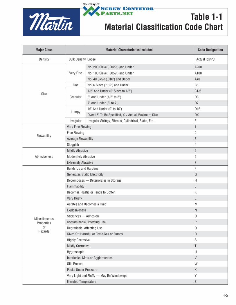
Major Class Material Characteristics Included Code Designation
Density Bulk Density, Loose Actual lbs/PC
Size
Very Fine
No. 200 Sieve (.0029") and Under A200
No. 100 Sieve (.0059") and Under A100
No. 40 Sieve (.016") and Under A40
Fine No. 6 Sieve (.132") and Under B6
Granular
1/2" And Under (6" Sieve to 1/2") C1/2
3" And Under (1/2" to 3") D3
7" And Under (3" to 7") D7
Lumpy16" And Under (0" to 16") D16
Over 16" To Be Specified, X = Actual Maximum Size DX
Irregular Irregular Stringy, Fibrous, Cylindrical, Slabs, Etc. E
Flowability
Very Free Flowing 1
Free Flowing 2
Average Flowability 3
Sluggish 4
Abrasiveness
Mildly Abrasive 5
Moderately Abrasive 6
Extremely Abrasive 7
MiscellaneousProperties
orHazards
Builds Up and Hardens F
Generates Static Electricity G
Decomposes — Deteriorates in Storage H
Flammability J
Becomes Plastic or Tends to Soften K
Very Dusty L
Aerates and Becomes a Fluid M
Explosiveness N
Stickiness — Adhesion O
Contaminable, Affecting Use P
Degradable, Affecting Use Q
Gives Off Harmful or Toxic Gas or Fumes R
Highly Corrosive S
Mildly Corrosive T
Hygroscopic U
Interlocks, Mats or Agglomerates V
Oils Present W
Packs Under Pressure X
Very Light and Fluffy — May Be Windswept Y
Elevated Temperature Z
Table 1-1
Material Classification Code Chart

H-6
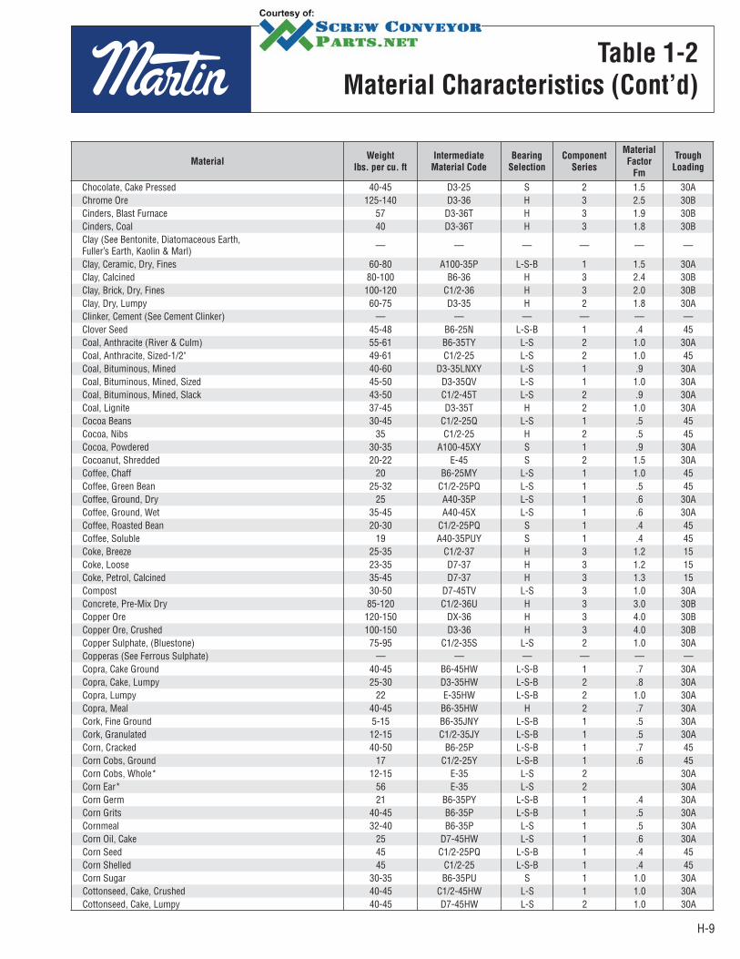
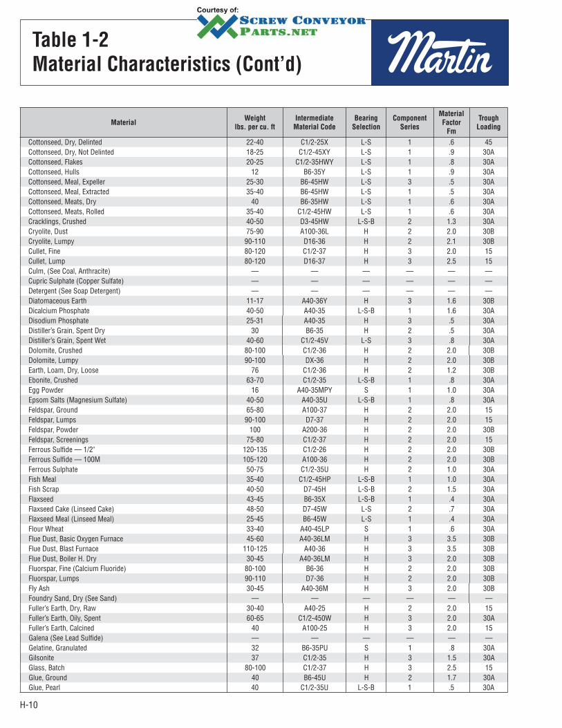
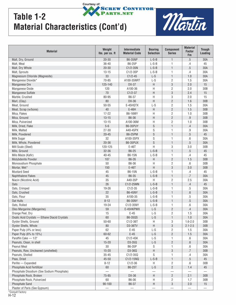
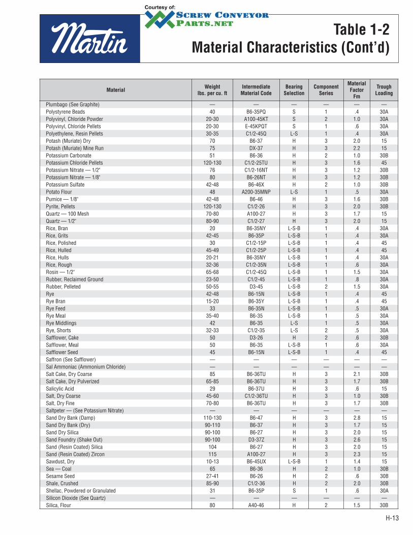
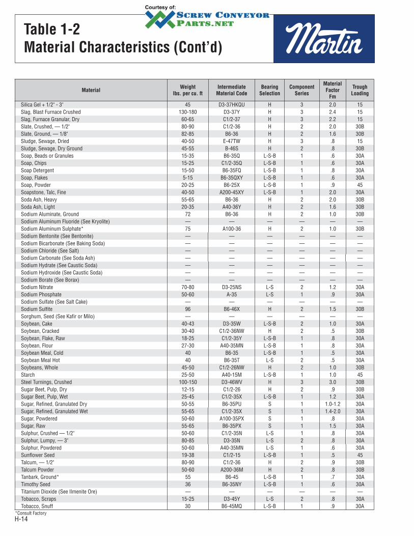
Table 1-2
Material Characteristics
Material Characteristics
The material characteristics table (page H-7 or H-15) lists the following Design Data for many materials.
A. The weight per cubic foot data may be used to calculate the required capacity of the conveyor in cubic feet per hour.
B. B. The material code for each material is as described in Table 1-1, and as interpreted below.
C. The Intermediate Bearing Selection Code is used to properly select the intermediate hanger bearing from Table 1-11 (Page H-22).
D. The Component Series Code is used to determine the correct components to be used as shown on page H-21.
E. The Material Factor Fm is used in determining horsepower as described on pages H-23 thru H-25.
F. The Trough Loading column indicates the proper percent of cross section loading to use in determining diameter and speed of the conveyor.
For screw conveyor design purposes, conveyed materials are classified in accordance with the code system in Table 1-1, and listed in Table 1-2.
Table 1-2 lists many materials that can be effectively conveyed by a screw conveyor. If a material is not listed in Table 1-2, it must be classified according to Table 1-1 or by referring to a listed material similar in weight, particle size and other characteristics.
HOW TO READ THE MATERIAL CODE
FROM TABLE 1-2
Material: Brewers Grain Spent Wet
C 1/2 4 5 T
SizeOther Characteristics
Flowability Abrasiveness

H-7
Table 1-2
Material Characteristics
MaterialWeight
lbs. per cu. ft
Intermediate
Material Code
Bearing
Selection
Component
Series
Material
Factor
Fm
Trough
Loading
Adipic Acid 45 A100-35 S 2 .5 30AAlfalfa Meal 14-22 B6-45WY H 2 .6 30AAlfalfa Pellets 41-43 C1/2-25 H 2 .5 45Alfalfa Seed 10-15 B6-15N L-S-B 1 .4 45Almonds, Broken 27-30 C1/2-35Q H 2 .9 30AAlmonds, Whole Shelled 28-30 C1/2-35Q H 2 .9 30AAlum, Fine 45-50 B6-35U L-S-B 1 .6 30AAlum, Lumpy 50-60 B6-25 L-S 2 1.4 45Alumina 55-65 B6-27MY H 3 1.8 15Alumina, Fine 35 A100-27MY H 3 1.6 15Alumina Sized or Briquette 65 D3-37 H 3 2.0 15Aluminate Gel (Aluminate Hydroxide) 45 B6-35 H 2 1.7 30AAluminum Chips, Dry 7-15 E-45V H 2 1.2 30AAluminum Chips, Oily 7-15 E-45V H 2 .8 30AAluminum Hydrate 13-20 C1/2-35 L-S-B 1 1.4 30AAluminum Ore (See Bauxite) — — — — — —Aluminum Oxide 60-120 A100-17M H 3 1.8 15Aluminum Silicate (Andalusite) 49 C1/2-35S L-S 3 .8 30AAluminum Sulfate 45-58 C1/2-25 L-S-B 1 1.0 45Ammonium Chloride, Crystalline 45-52 A100-45FRS L-S 3 .7 30AAmmonium Nitrate 45-62 A40-35NTU H 3 1.3 30AAmmonium Sulfate 45-58 C1/2-35FOTU L-S 1 1.0 30AAntimony Powder — A100-35 H 2 1.6 30AApple Pomace, Dry 15 C1/2-45Y H 2 1.0 30AArsenate Of Lead (See Lead Arsenate) — — — — — —Arsenic Oxide (Arsenolite) 100-120 A100-35R L-S-B — — 30AArsenic Pulverized 30 A100-25R H 2 .8 45Asbestos — Rock (Ore) 81 D3-37R H 3 1.2 15Asbestos — Shredded 20-40 E-46XY H 2 1.0 30BAsh, Black Ground 105 B6-35 L-S-B 1 2.0 30AAshes, Coal, Dry — 1/2" 35-45 C1/2-46TY H 3 3.0 30BAshes, Coal, Dry — 3" 35-40 D3-46T H 3 2.5 30BAshes, Coal, Wet — 1/2" 45-50 C1/2-46T H 3 3.0 30BAshes, Coal, Wet — 3" 45-50 D3-46T H 3 4.0 30BAshes, Fly (See Fly Ash) — — — — — —Asphalt, Crushed — 1/2" 45 C1/2-45 H 2 2.0 30ABagasse 7-10 E-45RVXY L-S-B 2 1.5 30ABakelite, Fine 30-45 B6-25 L-S-B 1 1.4 45Baking Powder 40-55 A100-35 S 1 .6 30ABaking Soda (Sodium Bicarbonate) 40-55 A100-25 S 1 .6 45Barite (Barium Sulfate) + 1/2" — 3" 120-180 D3-36 H 3 2.6 30BBarite, Powder 120-180 A100-35X H 2 2.0 30ABarium Carbonate 72 A100-45R H 2 1.6 30ABark, Wood, Refuse 10-20 E-45TVY H 3 2.0 30ABarley, Fine, Ground 24-38 B6-35 L-S-B 1 .4 30ABarley, Malted 31 C1/2-35 L-S-B 1 .4 30ABarley, Meal 28 C1/2-35 L-S-B 1 .4 30ABarley, Whole 36-48 B6-25N L-S-B 1 .5 45Basalt 80-105 B6-27 H 3 1.8 15Bauxite, Dry, Ground 68 B6-25 H 2 1.8 45Bauxite, Crushed — 3" 75-85 D3-36 H 3 2.5 30BBeans,Castor, Meal 35-40 B6-35W L-S-B 1 .8 30ABeans, Castor, Whole Shelled 36 C1/2-15W L-S-B 1 .5 45Beans, Navy, Dry 48 C1/2-15 L-S-B 1 .5 45Beans, Navy, Steeped 60 C1/2-25 L-S-B 1 .8 45 Bentonite, Crude 34-40 D3-45X H 2 1.2 30A
H-8
MaterialWeight
lbs. per cu. ft
Intermediate
Material Code
Bearing
Selection
Component
Series
Material
Factor
Fm
Trough
Loading
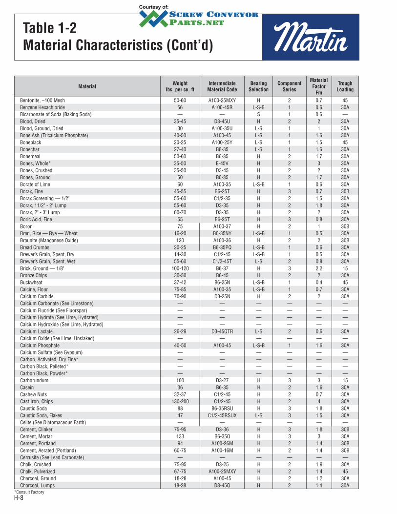
Bentonite, –100 Mesh 50-60 A100-25MXY H 2 0.7 45Benzene Hexachloride 56 A100-45R L-S-B 1 0.6 30ABicarbonate of Soda (Baking Soda) — — S 1 0.6 —Blood, Dried 35-45 D3-45U H 2 2 30ABlood, Ground, Dried 30 A100-35U L-S 1 1 30ABone Ash (Tricalcium Phosphate) 40-50 A100-45 L-S 1 1.6 30ABoneblack 20-25 A100-25Y L-S 1 1.5 45Bonechar 27-40 B6-35 L-S 1 1.6 30ABonemeal 50-60 B6-35 H 2 1.7 30ABones, Whole* 35-50 E-45V H 2 3 30ABones, Crushed 35-50 D3-45 H 2 2 30ABones, Ground 50 B6-35 H 2 1.7 30ABorate of Lime 60 A100-35 L-S-B 1 0.6 30ABorax, Fine 45-55 B6-25T H 3 0.7 30BBorax Screening — 1/2" 55-60 C1/2-35 H 2 1.5 30ABorax, 11/2" - 2" Lump 55-60 D3-35 H 2 1.8 30ABorax, 2" - 3" Lump 60-70 D3-35 H 2 2 30ABoric Acid, Fine 55 B6-25T H 3 0.8 30ABoron 75 A100-37 H 2 1 30BBran, Rice — Rye — Wheat 16-20 B6-35NY L-S-B 1 0.5 30ABraunite (Manganese Oxide) 120 A100-36 H 2 2 30BBread Crumbs 20-25 B6-35PQ L-S-B 1 0.6 30ABrewer’s Grain, Spent, Dry 14-30 C1/2-45 L-S-B 1 0.5 30ABrewer’s Grain, Spent, Wet 55-60 C1/2-45T L-S 2 0.8 30ABrick, Ground — 1/8" 100-120 B6-37 H 3 2.2 15Bronze Chips 30-50 B6-45 H 2 2 30ABuckwheat 37-42 B6-25N L-S-B 1 0.4 45Calcine, Flour 75-85 A100-35 L-S-B 1 0.7 30ACalcium Carbide 70-90 D3-25N H 2 2 30ACalcium Carbonate (See Limestone) — — — — — —Calcium Fluoride (See Fluorspar) — — — — — —Calcium Hydrate (See Lime, Hydrated) — — — — — —Calcium Hydroxide (See Lime, Hydrated) — — — — — —Calcium Lactate 26-29 D3-45QTR L-S 2 0.6 30ACalcium Oxide (See Lime, Unslaked) — — — — — —Calcium Phosphate 40-50 A100-45 L-S-B 1 1.6 30ACalcium Sulfate (See Gypsum) — — — — — —Carbon, Activated, Dry Fine* — — — — — —Carbon Black, Pelleted* — — — — — —Carbon Black, Powder* — — — — — —Carborundum 100 D3-27 H 3 3 15Casein 36 B6-35 H 2 1.6 30ACashew Nuts 32-37 C1/2-45 H 2 0.7 30ACast Iron, Chips 130-200 C1/2-45 H 2 4 30ACaustic Soda 88 B6-35RSU H 3 1.8 30ACaustic Soda, Flakes 47 C1/2-45RSUX L-S 3 1.5 30ACelite (See Diatomaceous Earth) — — — — — —Cement, Clinker 75-95 D3-36 H 3 1.8 30BCement, Mortar 133 B6-35Q H 3 3 30ACement, Portland 94 A100-26M H 2 1.4 30BCement, Aerated (Portland) 60-75 A100-16M H 2 1.4 30BCerrusite (See Lead Carbonate) — — — — — —Chalk, Crushed 75-95 D3-25 H 2 1.9 30AChalk, Pulverized 67-75 A100-25MXY H 2 1.4 45Charcoal, Ground 18-28 A100-45 H 2 1.2 30ACharcoal, Lumps 18-28 D3-45Q H 2 1.4 30A
Table 1-2
Material Characteristics (Cont’d)
*Consult Factory
H-9
Table 1-2
Material Characteristics (Cont’d)
MaterialWeight
lbs. per cu. ft
Intermediate
Material Code
Bearing
Selection
Component
Series
Material
Factor
Fm
Trough
Loading
Chocolate, Cake Pressed 40-45 D3-25 S 2 1.5 30AChrome Ore 125-140 D3-36 H 3 2.5 30BCinders, Blast Furnace 57 D3-36T H 3 1.9 30BCinders, Coal 40 D3-36T H 3 1.8 30BClay (See Bentonite, Diatomaceous Earth, Fuller’s Earth, Kaolin & Marl) — — — — — —
Clay, Ceramic, Dry, Fines 60-80 A100-35P L-S-B 1 1.5 30AClay, Calcined 80-100 B6-36 H 3 2.4 30BClay, Brick, Dry, Fines 100-120 C1/2-36 H 3 2.0 30BClay, Dry, Lumpy 60-75 D3-35 H 2 1.8 30AClinker, Cement (See Cement Clinker) — — — — — —Clover Seed 45-48 B6-25N L-S-B 1 .4 45Coal, Anthracite (River & Culm) 55-61 B6-35TY L-S 2 1.0 30ACoal, Anthracite, Sized-1/2" 49-61 C1/2-25 L-S 2 1.0 45Coal, Bituminous, Mined 40-60 D3-35LNXY L-S 1 .9 30ACoal, Bituminous, Mined, Sized 45-50 D3-35QV L-S 1 1.0 30ACoal, Bituminous, Mined, Slack 43-50 C1/2-45T L-S 2 .9 30ACoal, Lignite 37-45 D3-35T H 2 1.0 30ACocoa Beans 30-45 C1/2-25Q L-S 1 .5 45Cocoa, Nibs 35 C1/2-25 H 2 .5 45Cocoa, Powdered 30-35 A100-45XY S 1 .9 30ACocoanut, Shredded 20-22 E-45 S 2 1.5 30ACoffee, Chaff 20 B6-25MY L-S 1 1.0 45Coffee, Green Bean 25-32 C1/2-25PQ L-S 1 .5 45Coffee, Ground, Dry 25 A40-35P L-S 1 .6 30ACoffee, Ground, Wet 35-45 A40-45X L-S 1 .6 30ACoffee, Roasted Bean 20-30 C1/2-25PQ S 1 .4 45Coffee, Soluble 19 A40-35PUY S 1 .4 45Coke, Breeze 25-35 C1/2-37 H 3 1.2 15Coke, Loose 23-35 D7-37 H 3 1.2 15Coke, Petrol, Calcined 35-45 D7-37 H 3 1.3 15Compost 30-50 D7-45TV L-S 3 1.0 30AConcrete, Pre-Mix Dry 85-120 C1/2-36U H 3 3.0 30BCopper Ore 120-150 DX-36 H 3 4.0 30BCopper Ore, Crushed 100-150 D3-36 H 3 4.0 30BCopper Sulphate, (Bluestone) 75-95 C1/2-35S L-S 2 1.0 30ACopperas (See Ferrous Sulphate) — — — — — —Copra, Cake Ground 40-45 B6-45HW L-S-B 1 .7 30ACopra, Cake, Lumpy 25-30 D3-35HW L-S-B 2 .8 30ACopra, Lumpy 22 E-35HW L-S-B 2 1.0 30ACopra, Meal 40-45 B6-35HW H 2 .7 30ACork, Fine Ground 5-15 B6-35JNY L-S-B 1 .5 30ACork, Granulated 12-15 C1/2-35JY L-S-B 1 .5 30ACorn, Cracked 40-50 B6-25P L-S-B 1 .7 45Corn Cobs, Ground 17 C1/2-25Y L-S-B 1 .6 45Corn Cobs, Whole* 12-15 E-35 L-S 2 30ACorn Ear* 56 E-35 L-S 2 30ACorn Germ 21 B6-35PY L-S-B 1 .4 30ACorn Grits 40-45 B6-35P L-S-B 1 .5 30ACornmeal 32-40 B6-35P L-S 1 .5 30ACorn Oil, Cake 25 D7-45HW L-S 1 .6 30ACorn Seed 45 C1/2-25PQ L-S-B 1 .4 45Corn Shelled 45 C1/2-25 L-S-B 1 .4 45Corn Sugar 30-35 B6-35PU S 1 1.0 30ACottonseed, Cake, Crushed 40-45 C1/2-45HW L-S 1 1.0 30ACottonseed, Cake, Lumpy 40-45 D7-45HW L-S 2 1.0 30A
H-10
MaterialWeight
lbs. per cu. ft
Intermediate
Material Code
Bearing
Selection
Component
Series
Material
Factor
Fm
Trough
Loading
Cottonseed, Dry, Delinted 22-40 C1/2-25X L-S 1 .6 45Cottonseed, Dry, Not Delinted 18-25 C1/2-45XY L-S 1 .9 30ACottonseed, Flakes 20-25 C1/2-35HWY L-S 1 .8 30ACottonseed, Hulls 12 B6-35Y L-S 1 .9 30ACottonseed, Meal, Expeller 25-30 B6-45HW L-S 3 .5 30ACottonseed, Meal, Extracted 35-40 B6-45HW L-S 1 .5 30ACottonseed, Meats, Dry 40 B6-35HW L-S 1 .6 30ACottonseed, Meats, Rolled 35-40 C1/2-45HW L-S 1 .6 30ACracklings, Crushed 40-50 D3-45HW L-S-B 2 1.3 30ACryolite, Dust 75-90 A100-36L H 2 2.0 30BCryolite, Lumpy 90-110 D16-36 H 2 2.1 30BCullet, Fine 80-120 C1/2-37 H 3 2.0 15Cullet, Lump 80-120 D16-37 H 3 2.5 15Culm, (See Coal, Anthracite) — — — — — —Cupric Sulphate (Copper Sulfate) — — — — — —Detergent (See Soap Detergent) — — — — — —Diatomaceous Earth 11-17 A40-36Y H 3 1.6 30BDicalcium Phosphate 40-50 A40-35 L-S-B 1 1.6 30ADisodium Phosphate 25-31 A40-35 H 3 .5 30ADistiller’s Grain, Spent Dry 30 B6-35 H 2 .5 30ADistiller’s Grain, Spent Wet 40-60 C1/2-45V L-S 3 .8 30ADolomite, Crushed 80-100 C1/2-36 H 2 2.0 30BDolomite, Lumpy 90-100 DX-36 H 2 2.0 30BEarth, Loam, Dry, Loose 76 C1/2-36 H 2 1.2 30BEbonite, Crushed 63-70 C1/2-35 L-S-B 1 .8 30AEgg Powder 16 A40-35MPY S 1 1.0 30AEpsom Salts (Magnesium Sulfate) 40-50 A40-35U L-S-B 1 .8 30AFeldspar, Ground 65-80 A100-37 H 2 2.0 15Feldspar, Lumps 90-100 D7-37 H 2 2.0 15Feldspar, Powder 100 A200-36 H 2 2.0 30BFeldspar, Screenings 75-80 C1/2-37 H 2 2.0 15Ferrous Sulfide — 1/2" 120-135 C1/2-26 H 2 2.0 30BFerrous Sulfide — 100M 105-120 A100-36 H 2 2.0 30BFerrous Sulphate 50-75 C1/2-35U H 2 1.0 30AFish Meal 35-40 C1/2-45HP L-S-B 1 1.0 30AFish Scrap 40-50 D7-45H L-S-B 2 1.5 30AFlaxseed 43-45 B6-35X L-S-B 1 .4 30AFlaxseed Cake (Linseed Cake) 48-50 D7-45W L-S 2 .7 30AFlaxseed Meal (Linseed Meal) 25-45 B6-45W L-S 1 .4 30AFlour Wheat 33-40 A40-45LP S 1 .6 30AFlue Dust, Basic Oxygen Furnace 45-60 A40-36LM H 3 3.5 30BFlue Dust, Blast Furnace 110-125 A40-36 H 3 3.5 30BFlue Dust, Boiler H. Dry 30-45 A40-36LM H 3 2.0 30BFluorspar, Fine (Calcium Fluoride) 80-100 B6-36 H 2 2.0 30BFluorspar, Lumps 90-110 D7-36 H 2 2.0 30BFly Ash 30-45 A40-36M H 3 2.0 30BFoundry Sand, Dry (See Sand) — — — — — —Fuller’s Earth, Dry, Raw 30-40 A40-25 H 2 2.0 15Fuller’s Earth, Oily, Spent 60-65 C1/2-450W H 3 2.0 30AFuller’s Earth, Calcined 40 A100-25 H 3 2.0 15Galena (See Lead Sulfide) — — — — — —Gelatine, Granulated 32 B6-35PU S 1 .8 30AGilsonite 37 C1/2-35 H 3 1.5 30AGlass, Batch 80-100 C1/2-37 H 3 2.5 15Glue, Ground 40 B6-45U H 2 1.7 30AGlue, Pearl 40 C1/2-35U L-S-B 1 .5 30A
Table 1-2
Material Characteristics (Cont’d)

H-11
MaterialWeight
lbs. per cu. ft
Intermediate
Material Code
Bearing
Selection
Component
Series
Material
Factor
Fm
Trough
Loading
Glue, Veg. Powdered 40 A40-45U L-S-B 1 .6 30AGluten, Meal 40 B6-35P L-S 1 .6 30AGranite, Fine 80-90 C1/2-27 H 3 2.5 15Grape Pomace 15-20 D3-45U H 2 1.4 30AGraphite Flake 40 B6-25LP L-S-B 1 .5 45Graphite Flour 28 A100-35LMP L-S-B 1 .5 30AGraphite Ore 65-75 DX-35L H 2 1.0 30AGuano Dry* 70 C1/2-35 L-S 3 2.0 30AGypsum, Calcined 55-60 B6-35U H 2 1.6 30AGypsum, Calcined, Powdered 60-80 A100-35U H 2 2.0 30AGypsum, Raw — 1" 70-80 D3-25 H 2 2.0 30AHay, Chopped* 8-12 C1/2-35JY L-S 2 1.6 30AHexanedioic Acid (See Adipic Acid) — — — — — —Hominy, Dry 35-50 C1/2-25 L-S-B 1 .4 45Hops, Spent, Dry 35 D3-35 L-S-B 2 1.0 30AHops, Spent, Wet 50-55 D3-45V L-S 2 1.5 30AIce, Crushed 35-45 D3-35Q L-S 2 .4 30AIce, Flaked* 40-45 C1/2-35Q S 1 .6 30AIce, Cubes 33-35 D3-35Q S 1 .4 30AIce, Shell 33-35 D3-45Q S 1 .4 30AIlmenite Ore 140-160 D3-37 H 3 2.0 15Iron Ore Concentrate 120-180 A40-37 H 3 2.2 15Iron Oxide Pigment 25 A100-36LMP H 2 1.0 30BIron Oxide, Millscale 75 C1/2-36 H 2 1.6 30BIron Pyrites (See Ferrous Sulfide) — — — — — —Iron Sulphate (See Ferrous Sulfate) — — — — — —Iron Sulfide (See Ferrous Sulfide) — — — — — —Iron Vitriol (See Ferrous Sulfate) — — — — — —Kafir (Corn) 40-45 C1/2-25 H 3 .5 45Kaolin Clay 63 D3-25 H 2 2.0 30AKaolin Clay-Talc 32-56 A40-35LMP H 2 2.0 30AKryalith (See Cryolite) — — — — — —Lactose 32 A40-35PU S 1 .6 30ALamp Black (See Carbon Black) — — — — — —Lead Arsenate 72 A40-35R L-S-B 1 1.4 30ALead Arsenite 72 A40-35R L-S-B 1 1.4 30ALead Carbonate 240-260 A40-35R H 2 1.0 30ALead Ore — 1/8" 200-270 B6-35 H 3 1.4 30ALead Ore — 1/2" 180-230 C1/2-36 H 3 1.4 30BLead Oxide (Red Lead) — 100 Mesh 30-150 A100-35P H 2 1.2 30ALead Oxide (Red Lead) — 200 Mesh 30-180 A200-35LP H 2 1.2 30ALead Sulphide — 100 Mesh 240-260 A100-35R H 2 1.0 30ALignite (See Coal Lignite) — — — — — —Limanite, Ore, Brown 120 C1/2-47 H 3 1.7 15Lime, Ground, Unslaked 60-65 B6-35U L-S-B 1 .6 30ALime Hydrated 40 B6-35LM H 2 .8 30ALime, Hydrated, Pulverized 32-40 A40-35LM L-S 1 .6 30ALime, Pebble 53-56 C1/2-25HU L-S 2 2.0 45Limestone, Agricultural 68 B6-35 H 2 2.0 30ALimestone, Crushed 85-90 DX-36 H 2 2.0 30BLimestone, Dust 55-95 A40-46MY H 2 1.6-2.0 30BLindane (Benzene Hexachloride) — — — — — —Linseed (See Flaxseed) — — — — — —Litharge (Lead Oxide) — — — — — —Lithopone 45-50 A325-35MR L-S 1 1.0 30AMaize (See Milo) — — — — — —
Table 1-2
Material Characteristics (Cont’d)
*Consult Factory
H-12
Table 1-2
Material Characteristics (Cont’d)
MaterialWeight
lbs. per cu. ft
Intermediate
Material Code
Bearing
Selection
Component
Series
Material
Factor
Fm
Trough
Loading
Malt, Dry, Ground 20-30 B6-35NP L-S-B 1 .5 30AMalt, Meal 36-40 B6-25P L-S-B 1 .4 45Malt, Dry Whole 20-30 C1/2-35N L-S-B 1 .5 30AMalt, Sprouts 13-15 C1/2-35P L-S-B 1 .4 30AMagnesium Chloride (Magnesite) 33 C1/2-45 L-S 1 1.0 30AManganese Dioxide* 70-85 A100-35NRT L-S 2 1.5 30AManganese Ore 125-140 DX-37 H 3 2.0 15Manganese Oxide 120 A100-36 H 2 2.0 30BManganese Sulfate 70 C1/2-37 H 3 2.4 15Marble, Crushed 80-95 B6-37 H 3 2.0 15Marl, (Clay) 80 DX-36 H 2 1.6 30BMeat, Ground 50-55 E-45HQTX L-S 2 1.5 30AMeat, Scrap (w/bone) 40 E-46H H 2 1.5 30BMica, Flakes 17-22 B6-16MY H 2 1.0 30BMica, Ground 13-15 B6-36 H 2 .9 30BMica, Pulverized 13-15 A100-36M H 2 1.0 30BMilk, Dried, Flake 5-6 B6-35PUY S 1 .4 30AMilk, Malted 27-30 A40-45PX S 1 .9 30AMilk, Powdered 20-45 B6-25PM S 1 .5 45Milk Sugar 32 A100-35PX S 1 .6 30AMilk, Whole, Powdered 20-36 B6-35PUX S 1 .5 30AMill Scale (Steel) 120-125 E-46T H 3 3.0 30BMilo, Ground 32-36 B6-25 L-S-B 1 .5 45Milo Maize (Kafir) 40-45 B6-15N L-S-B 1 .4 45Molybdenite Powder 107 B6-26 H 2 1.5 30BMonosodium Phosphate 50 B6-36 H 2 .6 30BMortar, Wet* 150 E-46T H 3 3.0 30BMustard Seed 45 B6-15N L-S-B 1 .4 45Naphthalene Flakes 45 B6-35 L-S-B 1 .7 30ANiacin (Nicotinic Acid) 35 A40-35P H 2 2.5 30AOats 26 C1/2-25MN L-S-B 1 .4 45Oats, Crimped 19-26 C1/2-35 L-S-B 1 .5 30AOats, Crushed 22 B6-45NY L-S-B 1 .6 30AOats, Flour 35 A100-35 L-S-B 1 .5 30AOat Hulls 8-12 B6-35NY L-S-B 1 .5 30AOats, Rolled 19-24 C1/2-35NY L-S-B 1 .6 30AOleo Margarine (Margarine) 59 E-45HKPWX L-S 2 .4 30AOrange Peel, Dry 15 E-45 L-S 2 1.5 30AOxalic Acid Crystals — Ethane Diacid Crystals 60 B6-35QS L-S 1 1.0 30AOyster Shells, Ground 50-60 C1/2-36T H 3 1.6-2.0 30BOyster Shells, Whole 80 D3-36TV H 3 2.1-2.5 30BPaper Pulp (4% or less) 62 E-45 L-S 2 1.5 30APaper Pulp (6% to 15%) 60-62 E-45 L-S 2 1.5 30AParaffin Cake — 1/2" 45 C1/2-45K L-S 1 .6 30APeanuts, Clean, in shell 15-20 D3-35Q L-S 2 .6 30APeanut Meal 30 B6-35P S 1 .6 30APeanuts, Raw, Uncleaned (unshelled) 15-20 D3-36Q H 3 .7 30BPeanuts, Shelled 35-45 C1/2-35Q S 1 .4 30APeas, Dried 45-50 C1/2-15NQ L-S-B 1 .5 45Perlite — Expanded 8-12 C1/2-36 H 2 .6 30BPhosphate Acid Fertillizer 60 B6-25T L-S 2 1.4 45Phosphate Disodium (See Sodium Phosphate) — — — — — —Phosphate Rock, Broken 75-85 DX-36 H 2 2.1 30BPhosphate Rock, Pulverized 60 B6-36 H 2 1.7 30BPhosphate Sand 90-100 B6-37 H 3 2.0 15Plaster of Paris (See Gypsum) — — — — — —
*Consult Factory
H-13
MaterialWeight
lbs. per cu. ft
Intermediate
Material Code
Bearing
Selection
Component
Series
Material
Factor
Fm
Trough
Loading
Plumbago (See Graphite) — — — — — —Polystyrene Beads 40 B6-35PQ S 1 .4 30APolyvinyl, Chloride Powder 20-30 A100-45KT S 2 1.0 30APolyvinyl, Chloride Pellets 20-30 E-45KPQT S 1 .6 30APolyethylene, Resin Pellets 30-35 C1/2-45Q L-S 1 .4 30APotash (Muriate) Dry 70 B6-37 H 3 2.0 15Potash (Muriate) Mine Run 75 DX-37 H 3 2.2 15Potassium Carbonate 51 B6-36 H 2 1.0 30BPotassium Chloride Pellets 120-130 C1/2-25TU H 3 1.6 45Potassium Nitrate — 1/2" 76 C1/2-16NT H 3 1.2 30BPotassium Nitrate — 1/8" 80 B6-26NT H 3 1.2 30BPotassium Sulfate 42-48 B6-46X H 2 1.0 30BPotato Flour 48 A200-35MNP L-S 1 .5 30APumice — 1/8" 42-48 B6-46 H 3 1.6 30BPyrite, Pellets 120-130 C1/2-26 H 3 2.0 30BQuartz — 100 Mesh 70-80 A100-27 H 3 1.7 15Quartz — 1/2" 80-90 C1/2-27 H 3 2.0 15Rice, Bran 20 B6-35NY L-S-B 1 .4 30ARice, Grits 42-45 B6-35P L-S-B 1 .4 30ARice, Polished 30 C1/2-15P L-S-B 1 .4 45Rice, Hulled 45-49 C1/2-25P L-S-B 1 .4 45Rice, Hulls 20-21 B6-35NY L-S-B 1 .4 30ARice, Rough 32-36 C1/2-35N L-S-B 1 .6 30ARosin — 1/2" 65-68 C1/2-45Q L-S-B 1 1.5 30ARubber, Reclaimed Ground 23-50 C1/2-45 L-S-B 1 .8 30ARubber, Pelleted 50-55 D3-45 L-S-B 2 1.5 30ARye 42-48 B6-15N L-S-B 1 .4 45Rye Bran 15-20 B6-35Y L-S-B 1 .4 45Rye Feed 33 B6-35N L-S-B 1 .5 30ARye Meal 35-40 B6-35 L-S-B 1 .5 30ARye Middlings 42 B6-35 L-S 1 .5 30ARye, Shorts 32-33 C1/2-35 L-S 2 .5 30ASafflower, Cake 50 D3-26 H 2 .6 30BSafflower, Meal 50 B6-35 L-S-B 1 .6 30ASafflower Seed 45 B6-15N L-S-B 1 .4 45Saffron (See Safflower) — — — — — —Sal Ammoniac (Ammonium Chloride) — — — — — —Salt Cake, Dry Coarse 85 B6-36TU H 3 2.1 30BSalt Cake, Dry Pulverized 65-85 B6-36TU H 3 1.7 30BSalicylic Acid 29 B6-37U H 3 .6 15Salt, Dry Coarse 45-60 C1/2-36TU H 3 1.0 30BSalt, Dry Fine 70-80 B6-36TU H 3 1.7 30BSaltpeter — (See Potassium Nitrate) — — — — — —Sand Dry Bank (Damp) 110-130 B6-47 H 3 2.8 15Sand Dry Bank (Dry) 90-110 B6-37 H 3 1.7 15Sand Dry Silica 90-100 B6-27 H 3 2.0 15Sand Foundry (Shake Out) 90-100 D3-37Z H 3 2.6 15Sand (Resin Coated) Silica 104 B6-27 H 3 2.0 15Sand (Resin Coated) Zircon 115 A100-27 H 3 2.3 15Sawdust, Dry 10-13 B6-45UX L-S-B 1 1.4 15Sea — Coal 65 B6-36 H 2 1.0 30BSesame Seed 27-41 B6-26 H 2 .6 30BShale, Crushed 85-90 C1/2-36 H 2 2.0 30BShellac, Powdered or Granulated 31 B6-35P S 1 .6 30ASilicon Dioxide (See Quartz) — — — — — —Silica, Flour 80 A40-46 H 2 1.5 30B
Table 1-2
Material Characteristics (Cont’d)
H-14
MaterialWeight
lbs. per cu. ft
Intermediate
Material Code
Bearing
Selection
Component
Series
Material
Factor
Fm
Trough
Loading
Silica Gel + 1/2" - 3" 45 D3-37HKQU H 3 2.0 15Slag, Blast Furnace Crushed 130-180 D3-37Y H 3 2.4 15Slag, Furnace Granular, Dry 60-65 C1/2-37 H 3 2.2 15Slate, Crushed, — 1/2" 80-90 C1/2-36 H 2 2.0 30BSlate, Ground, — 1/8" 82-85 B6-36 H 2 1.6 30BSludge, Sewage, Dried 40-50 E-47TW H 3 .8 15Sludge, Sewage, Dry Ground 45-55 B-46S H 2 .8 30BSoap, Beads or Granules 15-35 B6-35Q L-S-B 1 .6 30ASoap, Chips 15-25 C1/2-35Q L-S-B 1 .6 30ASoap Detergent 15-50 B6-35FQ L-S-B 1 .8 30ASoap, Flakes 5-15 B6-35QXY L-S-B 1 .6 30ASoap, Powder 20-25 B6-25X L-S-B 1 .9 45Soapstone, Talc, Fine 40-50 A200-45XY L-S-B 1 2.0 30ASoda Ash, Heavy 55-65 B6-36 H 2 2.0 30BSoda Ash, Light 20-35 A40-36Y H 2 1.6 30BSodium Aluminate, Ground 72 B6-36 H 2 1.0 30BSodium Aluminum Fluoride (See Kryolite) — — — — — —Sodium Aluminum Sulphate* 75 A100-36 H 2 1.0 30BSodium Bentonite (See Bentonite) — — — — — —Sodium Bicarbonate (See Baking Soda) — — — — — —Sodium Chloride (See Salt) — — — — — —Sodium Carbonate (See Soda Ash) — — — — — —Sodium Hydrate (See Caustic Soda) — — — — — —Sodium Hydroxide (See Caustic Soda) — — — — — —Sodium Borate (See Borax) — — — — — —Sodium Nitrate 70-80 D3-25NS L-S 2 1.2 30ASodium Phosphate 50-60 A-35 L-S 1 .9 30ASodium Sulfate (See Salt Cake) — — — — — —Sodium Sulfite 96 B6-46X H 2 1.5 30BSorghum, Seed (See Kafir or Milo) — — — — — —Soybean, Cake 40-43 D3-35W L-S-B 2 1.0 30ASoybean, Cracked 30-40 C1/2-36NW H 2 .5 30BSoybean, Flake, Raw 18-25 C1/2-35Y L-S-B 1 .8 30ASoybean, Flour 27-30 A40-35MN L-S-B 1 .8 30ASoybean Meal, Cold 40 B6-35 L-S-B 1 .5 30ASoybean Meal Hot 40 B6-35T L-S 2 .5 30ASoybeans, Whole 45-50 C1/2-26NW H 2 1.0 30BStarch 25-50 A40-15M L-S-B 1 1.0 45Steel Turnings, Crushed 100-150 D3-46WV H 3 3.0 30BSugar Beet, Pulp, Dry 12-15 C1/2-26 H 2 .9 30BSugar Beet, Pulp, Wet 25-45 C1/2-35X L-S-B 1 1.2 30ASugar, Refined, Granulated Dry 50-55 B6-35PU S 1 1.0-1.2 30ASugar, Refined, Granulated Wet 55-65 C1/2-35X S 1 1.4-2.0 30ASugar, Powdered 50-60 A100-35PX S 1 .8 30ASugar, Raw 55-65 B6-35PX S 1 1.5 30ASulphur, Crushed — 1/2" 50-60 C1/2-35N L-S 1 .8 30ASulphur, Lumpy, — 3" 80-85 D3-35N L-S 2 .8 30ASulphur, Powdered 50-60 A40-35MN L-S 1 .6 30ASunflower Seed 19-38 C1/2-15 L-S-B 1 .5 45Talcum, — 1/2" 80-90 C1/2-36 H 2 .9 30BTalcum Powder 50-60 A200-36M H 2 .8 30BTanbark, Ground* 55 B6-45 L-S-B 1 .7 30ATimothy Seed 36 B6-35NY L-S-B 1 .6 30ATitanium Dioxide (See Ilmenite Ore) — — — — — —Tobacco, Scraps 15-25 D3-45Y L-S 2 .8 30ATobacco, Snuff 30 B6-45MQ L-S-B 1 .9 30A
Table 1-2
Material Characteristics (Cont’d)
*Consult Factory

H-15
MaterialWeight
lbs. per cu. ft
Intermediate
Material Code
Bearing
Selection
Component
Series
Material
Factor
Fm
Trough
Loading
Tricalcium Phosphate 40-50 A40-45 L-S 1 1.6 30ATriple Super Phosphate 50-55 B6-36RS H 3 2.0 30BTrisodium Phosphate 60 C1/2-36 H 2 1.7 30BTrisodium Phosphate Granular 60 B6-36 H 2 1.7 30BTrisodium Phosphate, Pulverized 50 A40-36 H 2 1.6 30BTung Nut Meats, Crushed 28 D3-25W L-S 2 .8 30ATung Nuts 25-30 D3-15 L-S 2 .7 30AUrea Prills, Coated 43-46 B6-25 L-S-B 1 1.2 45Vermiculite, Expanded 16 C1/2-35Y L-S 1 .5 30AVermiculite, Ore 80 D3-36 H 2 1.0 30BVetch 48 B6-16N L-S-B 1 .4 30BWalnut Shells, Crushed 35-45 B6-36 H 2 1.0 30BWheat 45-48 C1/2-25N L-S-B 1 .4 45Wheat, Cracked 40-45 B6-25N L-S-B 1 .4 45Wheat, Germ 18-28 B6-25 L-S-B 1 .4 45White Lead, Dry 75-100 A40-36MR H 2 1.0 30BWood Chips, Screened 10-30 D3-45VY L-S 2 .6 30AWood Flour 16-36 B6-35N L-S 1 .4 30AWood Shavings 8-16 E-45VY L-S 2 1.5 30AZinc, Concentrate Residue 75-80 B6-37 H 3 1.0 15Zinc Oxide, Heavy 30-35 A100-45X L-S 1 1.0 30AZinc Oxide, Light 10-15 A100-45XY L-S 1 1.0 30A
Table 1-2
Material Characteristics (Cont’d)
*Consult Factory
H-16
Selection of Conveyor
Size and Speed
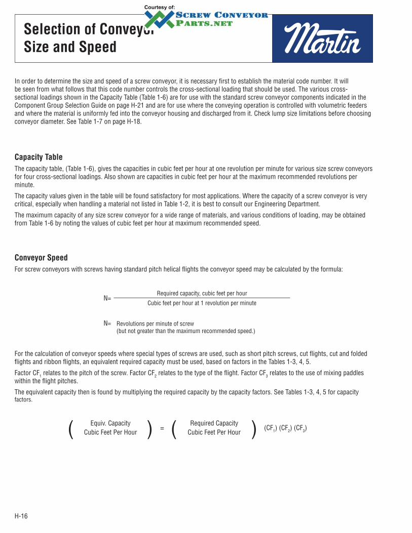
In order to determine the size and speed of a screw conveyor, it is necessary first to establish the material code number. It will be seen from what follows that this code number controls the cross-sectional loading that should be used. The various cross-sectional loadings shown in the Capacity Table (Table 1-6) are for use with the standard screw conveyor components indicated in the Component Group Selection Guide on page H-21 and are for use where the conveying operation is controlled with volumetric feeders and where the material is uniformly fed into the conveyor housing and discharged from it. Check lump size limitations before choosing conveyor diameter. See Table 1-7 on page H-18.
Capacity Table
The capacity table, (Table 1-6), gives the capacities in cubic feet per hour at one revolution per minute for various size screw conveyors for four cross-sectional loadings. Also shown are capacities in cubic feet per hour at the maximum recommended revolutions per minute.
The capacity values given in the table will be found satisfactory for most applications. Where the capacity of a screw con veyor is very critical, especially when handling a material not listed in Table 1-2, it is best to consult our Engineering Department.
The maximum capacity of any size screw conveyor for a wide range of materials, and various conditions of loading, may be obtained from Table 1-6 by noting the values of cubic feet per hour at maximum recommended speed.
Conveyor Speed
For screw conveyors with screws having standard pitch helical flights the conveyor speed may be calculated by the formula:
N=Required capacity, cubic feet per hour
Cubic feet per hour at 1 revolution per minute
N= Revolutions per minute of screw (but not greater than the maximum recommended speed.)
For the calculation of conveyor speeds where special types of screws are used, such as short pitch screws, cut flights, cut and folded flights and ribbon flights, an equivalent required capacity must be used, based on factors in the Tables 1-3, 4, 5.
Factor CF1 relates to the pitch of the screw. Factor CF2 relates to the type of the flight. Factor CF3 relates to the use of mixing paddles within the flight pitches.
The equivalent capacity then is found by multiplying the required capacity by the capacity factors. See Tables 1-3, 4, 5 for capacity factors.
( Equiv. CapacityCubic Feet Per Hour ) = ( Required Capacity
Cubic Feet Per Hour ) (CF1) (CF2) (CF3)
H-17
Capacity
Factors
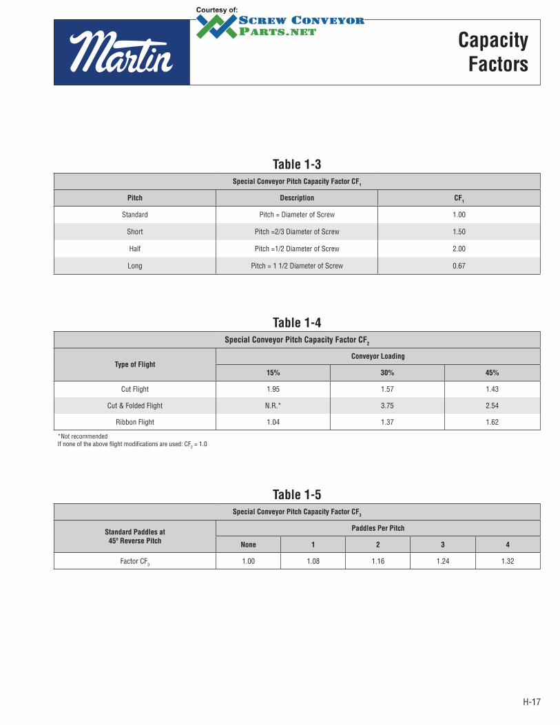
Table 1-3
Special Conveyor Pitch Capacity Factor CF1
Pitch Description CF1
Standard Pitch = Diameter of Screw 1.00
Short Pitch =2/3 Diameter of Screw 1.50
Half Pitch =1/2 Diameter of Screw 2.00
Long Pitch = 1 1/2 Diameter of Screw 0.67
Table 1-4
Special Conveyor Pitch Capacity Factor CF2
Type of Flight
Conveyor Loading
15% 30% 45%
Cut Flight 1.95 1.57 1.43
Cut & Folded Flight N.R.* 3.75 2.54
Ribbon Flight 1.04 1.37 1.62
*Not recommendedIf none of the above flight modifications are used: CF2 = 1.0
Table 1-5
Special Conveyor Pitch Capacity Factor CF3
Standard Paddles at
45º Reverse Pitch
Paddles Per Pitch
None 1 2 3 4
Factor CF3 1.00 1.08 1.16 1.24 1.32
H-18
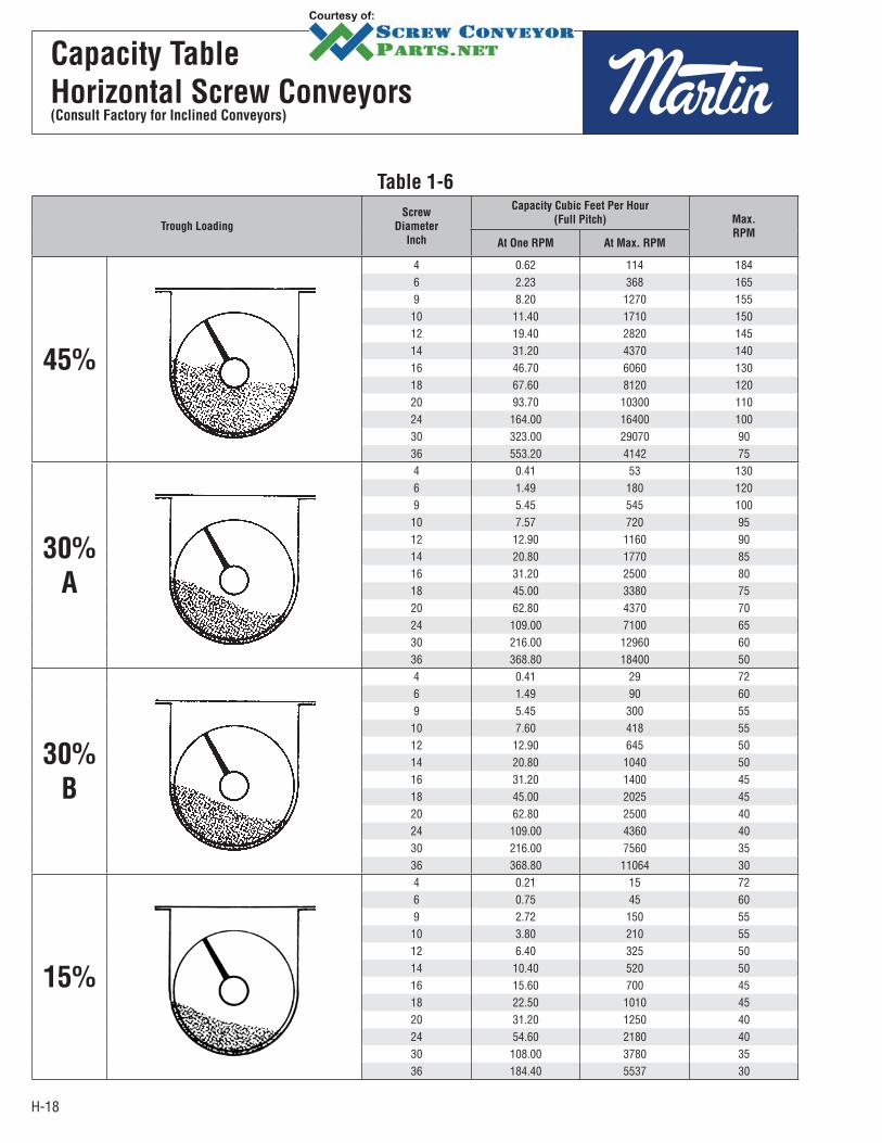
Capacity Table
Horizontal Screw Conveyors(Consult Factory for Inclined Conveyors)
Table 1-6
Trough Loading
Screw
Diameter
Inch
Capacity Cubic Feet Per Hour
(Full Pitch) Max.
RPMAt One RPM At Max. RPM
45%
4 0.62 114 1846 2.23 368 1659 8.20 1270 15510 11.40 1710 15012 19.40 2820 14514 31.20 4370 14016 46.70 6060 13018 67.60 8120 12020 93.70 10300 11024 164.00 16400 10030 323.00 29070 9036 553.20 4142 75
30%
A
4 0.41 53 1306 1.49 180 1209 5.45 545 10010 7.57 720 9512 12.90 1160 9014 20.80 1770 8516 31.20 2500 8018 45.00 3380 7520 62.80 4370 7024 109.00 7100 6530 216.00 12960 6036 368.80 18400 50
30%
B
4 0.41 29 726 1.49 90 609 5.45 300 5510 7.60 418 5512 12.90 645 5014 20.80 1040 5016 31.20 1400 4518 45.00 2025 4520 62.80 2500 4024 109.00 4360 4030 216.00 7560 3536 368.80 11064 30
15%
4 0.21 15 726 0.75 45 609 2.72 150 5510 3.80 210 5512 6.40 325 5014 10.40 520 5016 15.60 700 4518 22.50 1010 4520 31.20 1250 4024 54.60 2180 4030 108.00 3780 3536 184.40 5537 30
H-19
Lump Size
Limitations
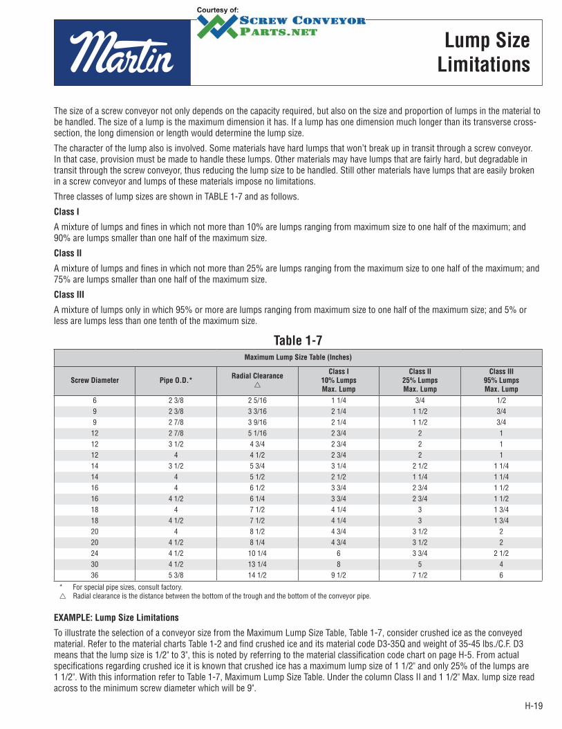
The size of a screw conveyor not only depends on the capacity required, but also on the size and proportion of lumps in the material to be handled. The size of a lump is the maximum dimension it has. If a lump has one dimension much longer than its transverse cross-section, the long dimension or length would determine the lump size.
The character of the lump also is involved. Some materials have hard lumps that won’t break up in transit through a screw conveyor. In that case, provision must be made to handle these lumps. Other materials may have lumps that are fairly hard, but degradable in transit through the screw conveyor, thus reducing the lump size to be handled. Still other materials have lumps that are easily broken in a screw conveyor and lumps of these materials impose no limitations.
Three classes of lump sizes are shown in TABLE 1-7 and as follows.
Class I
A mixture of lumps and fines in which not more than 10% are lumps ranging from maximum size to one half of the maximum; and 90% are lumps smaller than one half of the maximum size.
Class II
A mixture of lumps and fines in which not more than 25% are lumps ranging from the maximum size to one half of the maximum; and 75% are lumps smaller than one half of the maximum size.
Class III
A mixture of lumps only in which 95% or more are lumps ranging from maximum size to one half of the maximum size; and 5% or less are lumps less than one tenth of the maximum size.
EXAMPLE: Lump Size Limitations
To illustrate the selection of a conveyor size from the Maximum Lump Size Table, Table 1-7, consider crushed ice as the conveyed material. Refer to the material charts Table 1-2 and find crushed ice and its material code D3-35Q and weight of 35-45 lbs./C.F. D3 means that the lump size is 1/2" to 3", this is noted by referring to the material classification code chart on page H-5. From actual specifications regarding crushed ice it is known that crushed ice has a maximum lump size of 1 1/2" and only 25% of the lumps are 1 1/2". With this information refer to Table 1-7, Maximum Lump Size Table. Under the column Class II and 1 1/2" Max. lump size read across to the minimum screw diameter which will be 9".
Table 1-7
Maximum Lump Size Table (Inches)
Screw Diameter Pipe O.D.*Radial Clearance
Class I
10% Lumps
Max. Lump
Class II
25% Lumps
Max. Lump
Class III
95% Lumps
Max. Lump
6 2 3/8 2 5/16 1 1/4 3/4 1/2 9 2 3/8 3 3/16 2 1/4 1 1/2 3/4 9 2 7/8 3 9/16 2 1/4 1 1/2 3/4
12 2 7/8 5 1/16 2 3/4 2 1 12 3 1/2 4 3/4 2 3/4 2 1 12 4 4 1/2 2 3/4 2 1 14 3 1/2 5 3/4 3 1/4 2 1/2 1 1/4 14 4 5 1/2 2 1/2 1 1/4 1 1/4 16 4 6 1/2 3 3/4 2 3/4 1 1/2 16 4 1/2 6 1/4 3 3/4 2 3/4 1 1/2 18 4 7 1/2 4 1/4 3 1 3/4 18 4 1/2 7 1/2 4 1/4 3 1 3/4 20 4 8 1/2 4 3/4 3 1/2 2 20 4 1/2 8 1/4 4 3/4 3 1/2 2 24 4 1/2 10 1/4 6 3 3/4 2 1/2 30 4 1/2 13 1/4 8 5 4 36 5 3/8 14 1/2 9 1/2 7 1/2 6
* For special pipe sizes, consult factory. Radial clearance is the distance between the bottom of the trough and the bottom of the conveyor pipe.

H-20
Component
Selection
Component Groups
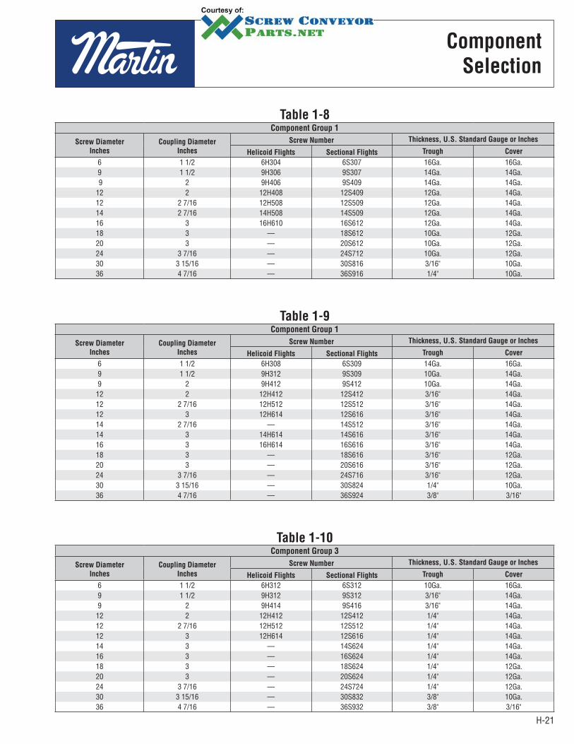
To facilitate the selection of proper specifications for a screw conveyor for a particular duty, screw conveyors are broken down into three Component Groups. These groups relate both to the Material Classification Code and also to screw size, pipe size, type of bearings and trough thickness.
Referring to Table 1-2, find the component series designation of the material to be conveyed.
Having made the Component Series selection, refer to Tables 1-8, 9, 10 which give the specifications of the various sizes of conveyor screws. (The tabulated screw numbers in this table refer to standard specifications for screws found on pages H-77 − H-85 Component Section.) These standards give complete data on the screws such as the length of standard sections, minimum edge thickness of screw flight, bushing data, bolt size, bolt spacing, etc.
EXAMPLE: For a screw conveyor to handle brewers grain, spent wet, refer to the material characteristics Table 1-2. Note that the component series column refers to series 2. Refer now to page H-21, component selection, Table 1-9, component group 2. The standard shaft sizes, screw flight designations, trough gauges and cover gauges are listed for each screw diameter.
H-21
Component
Selection
Table 1-8Component Group 1
Screw Diameter
Inches
Coupling Diameter
Inches
Screw Number Thickness, U.S. Standard Gauge or Inches
Helicoid Flights Sectional Flights Trough Cover
6 1 1/2 6H304 6S307 16Ga. 16Ga.9 1 1/2 9H306 9S307 14Ga. 14Ga. 9 2 9H406 9S409 14Ga. 14Ga.12 2 12H408 12S409 12Ga. 14Ga.12 2 7/16 12H508 12S509 12Ga. 14Ga.14 2 7/16 14H508 14S509 12Ga. 14Ga.16 3 16H610 16S612 12Ga. 14Ga.18 3 — 18S612 10Ga. 12Ga.20 3 — 20S612 10Ga. 12Ga.24 3 7/16 — 24S712 10Ga. 12Ga.30 3 15/16 — 30S816 3/16" 10Ga.36 4 7/16 — 36S916 1/4" 10Ga.
Table 1-9Component Group 1
Screw Diameter
Inches
Coupling Diameter
Inches
Screw Number Thickness, U.S. Standard Gauge or Inches
Helicoid Flights Sectional Flights Trough Cover
6 1 1/2 6H308 6S309 14Ga. 16Ga.9 1 1/2 9H312 9S309 10Ga. 14Ga.9 2 9H412 9S412 10Ga. 14Ga.
12 2 12H412 12S412 3/16" 14Ga.12 2 7/16 12H512 12S512 3/16" 14Ga.12 3 12H614 12S616 3/16" 14Ga.14 2 7/16 — 14S512 3/16" 14Ga.14 3 14H614 14S616 3/16" 14Ga.16 3 16H614 16S616 3/16" 14Ga.18 3 — 18S616 3/16" 12Ga.20 3 — 20S616 3/16" 12Ga.24 3 7/16 — 24S716 3/16" 12Ga.30 3 15/16 — 30S824 1/4" 10Ga.36 4 7/16 — 36S924 3/8" 3/16"
Table 1-10Component Group 3
Screw Diameter
Inches
Coupling Diameter
Inches
Screw Number Thickness, U.S. Standard Gauge or Inches
Helicoid Flights Sectional Flights Trough Cover
6 1 1/2 6H312 6S312 10Ga. 16Ga.9 1 1/2 9H312 9S312 3/16" 14Ga.9 2 9H414 9S416 3/16" 14Ga.
12 2 12H412 12S412 1/4" 14Ga.12 2 7/16 12H512 12S512 1/4" 14Ga.12 3 12H614 12S616 1/4" 14Ga.14 3 — 14S624 1/4" 14Ga.16 3 — 16S624 1/4" 14Ga.18 3 — 18S624 1/4" 12Ga.20 3 — 20S624 1/4" 12Ga.24 3 7/16 — 24S724 1/4" 12Ga.30 3 15/16 — 30S832 3/8" 10Ga.36 4 7/16 — 36S932 3/8" 3/16"
H-22
Bearing
Selection
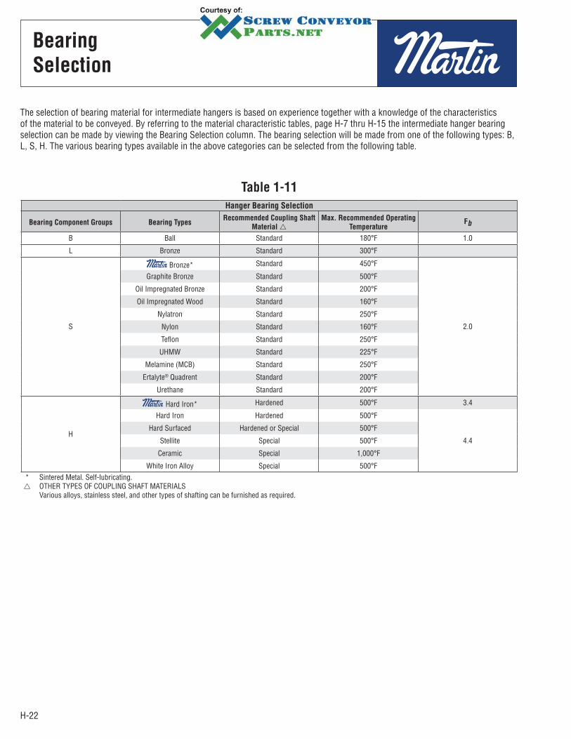
The selection of bearing material for intermediate hangers is based on experience together with a knowledge of the characteristics of the material to be conveyed. By referring to the material characteristic tables, page H-7 thru H-15 the intermediate hanger bearing selection can be made by viewing the Bearing Selection column. The bearing selection will be made from one of the following types: B, L, S, H. The various bearing types available in the above categories can be selected from the following table.
Table 1-11
Hanger Bearing Selection
Bearing Component Groups Bearing TypesRecommended Coupling Shaft
Material
Max. Recommended Operating
TemperatureFb
B Ball Standard 180°F 1.0
L Bronze Standard 300°F
S
Bronze* Standard 450°F
2.0
Graphite Bronze Standard 500°F
Oil Impregnated Bronze Standard 200°F
Oil Impregnated Wood Standard 160°F
Nylatron Standard 250°F
Nylon Standard 160°F
Teflon Standard 250°F
UHMW Standard 225°F
Melamine (MCB) Standard 250°F
Ertalyte® Quadrent Standard 200°F
Urethane Standard 200°F
H
Hard Iron* Hardened 500°F 3.4
Hard Iron Hardened 500°F
4.4
Hard Surfaced Hardened or Special 500°F
Stellite Special 500°F
Ceramic Special 1,000°F
White Iron Alloy Special 500°F * Sintered Metal. Self-lubricating.
OTHER TYPES OF COUPLING SHAFT MATERIALS Various alloys, stainless steel, and other types of shafting can be furnished as required.
H-23
Horsepower
Requirements
Table 1-13Hanger Bearing Selection
Bearing Types Hanger Bearing Fb
B Ball 1.0
L Bronze
S
* Graphite Bronze
2.0
* Oil Impregnated Bronze * Oil Impregnated Wood * Nylatron * Nylon * Teflon * UHMW * Melamine (MCB) * Ertalyte® Quadrent * Urethane
H
* Hard Iron* 3.4
* Hard Iron
4.4* Stellite * Ceramic * White Iron Alloy
* Non lubricated bearings, or bearings not additionally lubricated.
Table 1-12Conveyor Diameter Factor, Fd
Screw Diameter (Inches) Factor Fd
4 12.06 18.09 31.010 37.012 55.014 78.016 106.018 135.020 165.024 235.030 365.036 540.0
Horizontal Screw Conveyors
*Consult Factory for Inclined Conveyors or Screw Feeders
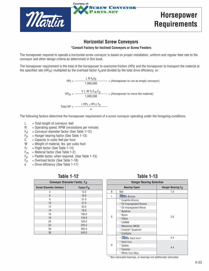
The horsepower required to operate a horizontal screw conveyor is based on proper installation, uniform and regular feed rate to the conveyor and other design criteria as determined in this book.
The horsepower requirement is the total of the horsepower to overcome friction (HPf) and the horsepower to transport the material at the specified rate (HPm) multiplied by the overload factor Fo and divided by the total drive efficiency, or:
HPf =L N Fd fb = (Horsepower to run an empty conveyor)
1,000,000
HPm =C L W Ff Fm Fp = (Horsepower to move the material)
1,000,000
Total HP =( HPf + HPf ) Fo
e
The following factors determine the horsepower requirement of a screw conveyor operating under the foregoing conditions.
L = Total length of conveyor, feetN = Operating speed, RPM (revolutions per minute)Fd = Conveyor diameter factor (See Table 1-12)Fb = Hanger bearing factor (See Table 1-13)C = Capacity in cubic feet per hourW = Weight of material, lbs. per cubic footFf = Flight factor (See Table 1-14)Fm = Material factor (See Table 1-2)Fp = Paddle factor, when required. (See Table 1-15)Fo = Overload factor (See Table 1-16)e = Drive efficiency (See Table 1-17)
H-24
Horsepower Factor
Tables
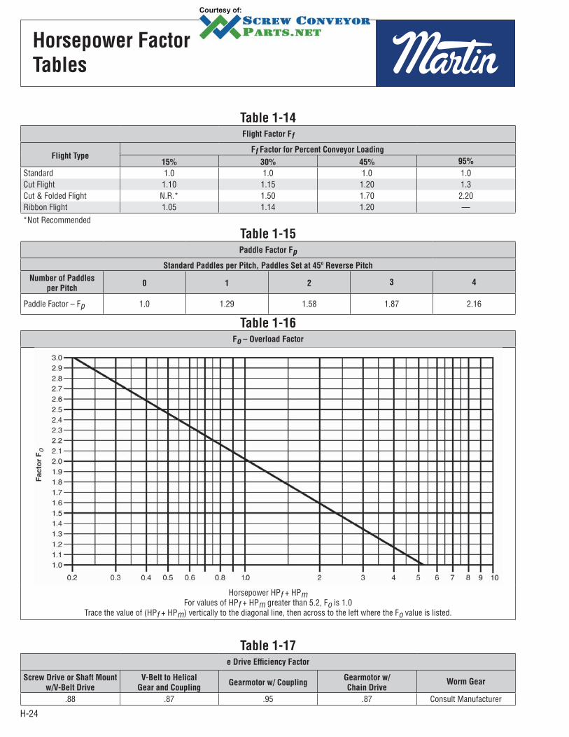
Table 1-14Flight Factor Ff
Flight TypeFf Factor for Percent Conveyor Loading
15% 30% 45% 95%
Standard 1.0 1.0 1.0 1.0Cut Flight 1.10 1.15 1.20 1.3Cut & Folded Flight N.R.* 1.50 1.70 2.20Ribbon Flight 1.05 1.14 1.20 —*Not Recommended
Table 1-16Fo – Overload Factor
Horsepower HPf + HPmFor values of HPf + HPm greater than 5.2, Fo is 1.0
Trace the value of (HPf + HPm) vertically to the diagonal line, then across to the left where the Fo value is listed.
Table 1-15Paddle Factor Fp
Standard Paddles per Pitch, Paddles Set at 45º Reverse Pitch
Number of Paddles
per Pitch0 1 2 3 4
Paddle Factor – Fp 1.0 1.29 1.58 1.87 2.16
Table 1-17e Drive Efficiency Factor
Screw Drive or Shaft Mount
w/V-Belt Drive
V-Belt to Helical
Gear and CouplingGearmotor w/ Coupling
Gearmotor w/
Chain DriveWorm Gear
.88 .87 .95 .87 Consult Manufacturer
H-25
Horsepower
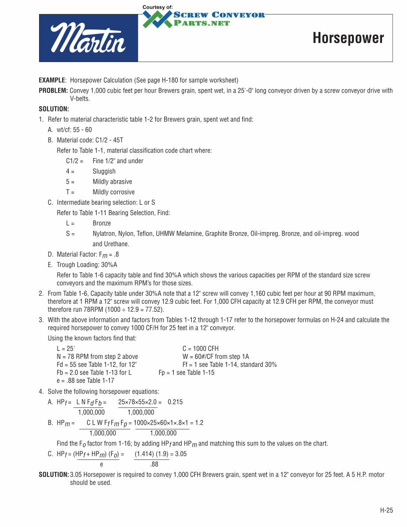
EXAMPLE: Horsepower Calculation (See page H-180 for sample worksheet)
PROBLEM: Convey 1,000 cubic feet per hour Brewers grain, spent wet, in a 25'-0" long conveyor driven by a screw conveyor drive with V-belts.
SOLUTION:
1. Refer to material characteristic table 1-2 for Brewers grain, spent wet and find:
A. wt/cf: 55 - 60
B. Material code: C1/2 - 45T
Refer to Table 1-1, material classification code chart where:
C1/2 = Fine 1/2" and under
4 = Sluggish
5 = Mildly abrasive
T = Mildly corrosive
C. Intermediate bearing selection: L or S
Refer to Table 1-11 Bearing Selection, Find:
L = Bronze
S = Nylatron, Nylon, Teflon, UHMW Melamine, Graphite Bronze, Oil-impreg. Bronze, and oil-impreg. wood
and Urethane.
D. Material Factor: Fm = .8
E. Trough Loading: 30%A
Refer to Table 1-6 capacity table and find 30%A which shows the various capacities per RPM of the standard size screw conveyors and the maximum RPM’s for those sizes.
2. From Table 1-6, Capacity table under 30%A note that a 12" screw will convey 1,160 cubic feet per hour at 90 RPM maximum, therefore at 1 RPM a 12" screw will convey 12.9 cubic feet. For 1,000 CFH capacity at 12.9 CFH per RPM, the conveyor must therefore run 78RPM (1000 ÷ 12.9 = 77.52).
3. With the above information and factors from Tables 1-12 through 1-17 refer to the horsepower formulas on H-24 and calculate the required horsepower to convey 1000 CF/H for 25 feet in a 12" conveyor.
Using the known factors find that:
L = 25' C = 1000 CFH N = 78 RPM from step 2 above W = 60#/CF from step 1A Fd = 55 see Table 1-12, for 12" Ff = 1 see Table 1-14, standard 30% Fb = 2.0 see Table 1-13 for L Fp = 1 see Table 1-15 e = .88 see Table 1-17
4. Solve the following horsepower equations:
A. HPf = L N Fd Fb = 25×78×55×2.0 = 0.215
1,000,000 1,000,000
B. HPm = C L W Ff Fm Fp = 1000×25×60×1×.8×1 = 1.2
1,000,000 1,000,000
Find the Fo factor from 1-16; by adding HPf and HPm and matching this sum to the values on the chart.
C. HPf = (HPf + HPm) (Fo) = (1.414) (1.9) = 3.05
e .88
SOLUTION: 3.05 Horsepower is required to convey 1,000 CFH Brewers grain, spent wet in a 12" conveyor for 25 feet. A 5 H.P. motor should be used.

H-26
Torsional Ratings of
Conveyor Screw Parts
Screw conveyors are limited in overall design by the amount of torque that can be safely transmitted through the pipes, couplings, and coupling bolts.
The table below combines the various torsional ratings of bolts, couplings and pipes so that it is easy to compare the torsional ratings of all the stressed parts of standard conveyor screws.
Table 1-18
Shaft Dia.
In.
Pipe Couplings
Dia.
In.Size
In.
Torque
In.
Lbs.
Torque In.
Lbs. *
Bolts in Shear In. Lbs. Bolts in Bearing In. Lbs.
No. of Bolts Used No. of Bolts Used
C 1018 C 1045 2 3 2 3
1 1 1/4 3,140 820 1,025 3/8 1,380 2,070 1,970 2,955 1 1/2 2 7,500 3,070 3,850 1/2 3,660 5,490 5,000 7,5002 2 1/2 14,250 7,600 9,500 5/8 7,600 11,400 7,860 11,7902 7/16 3 23,100 15,030 18,780 5/8 9,270 13,900 11,640 17,4603 3 1/2 32,100 28,350 35,440 3/4 16,400 24,600 15,540 23,3103 4 43,000 28,350 35,440 3/4 16,400 24,600 25,000 37,5003 7/16 4 43,300 42,470 53,080 7/8 25,600 38,400 21,800 32,7003 15/16 5 65,100 61,190 76,485 1 1/8 48,540 72,810 52,120 78,1804 7/16 6 101,160 88,212 110,265 1 1/4 67,520 101,280 90,750 136,125
Values shown are for A307 64, Grade 2 Bolts. Values for Grade 5 Bolts are above × 2.5. * Values are for unheattreated shafts.
The lowest torsional rating figure for any given component will be the one that governs how much torque may be safely transmitted. For example, using standard unhardened two bolt coupling shafts, the limiting torsional strength of each part is indicated in Table 1-18.
Thus it can be seen that the shaft itself is the limiting factor on 1", 1 1/2" and 2" couplings. The bolts in shear are the limiting factors on the 2-7/16" coupling and on the 3" coupling used in conjunction with 4" pipe. The bolts in bearing are the limiting factors for the 3" coupling used in conjunction with 3 1/2" pipe, and for the 3-7/16" coupling.
FORMULA: Horsepower To Torque (In. Lbs.)
63,025 × HP = Torque (In. Lbs.) RPM
EXAMPLE: 12" Screw, 78 RPM, 5 Horsepower
63,025 × 5 = 4,040 In. Lbs. 78
From the table above 2" shafts with 2 bolt drilling and 2 1/2" std. pipe are adequate (4,040 < 7600).
If the torque is greater than the values in the above table, such as in 2" couplings (torque > 7600), then hardened shafts can be used as long as the torque is less than the value for hardened couplings (torque < 9500). If the torque is greater than the 2 bolt in shear value but less than the 3 bolt in shear value then 3 bolt coupling can be used. The same applies with bolts in bearing. When the transmitted torque is greater than the pipe size value, then larger pipe or heavier wall pipe may be used. Other solutions include: high torque bolts to increase bolt in shear rating, external collars, or bolt pads welded to pipe to increase bolt in bearing transmission. For solutions other than those outlined in the above table please consult our Engineering Department.
H-27
Horsepower Ratings of
Conveyor Screw Parts
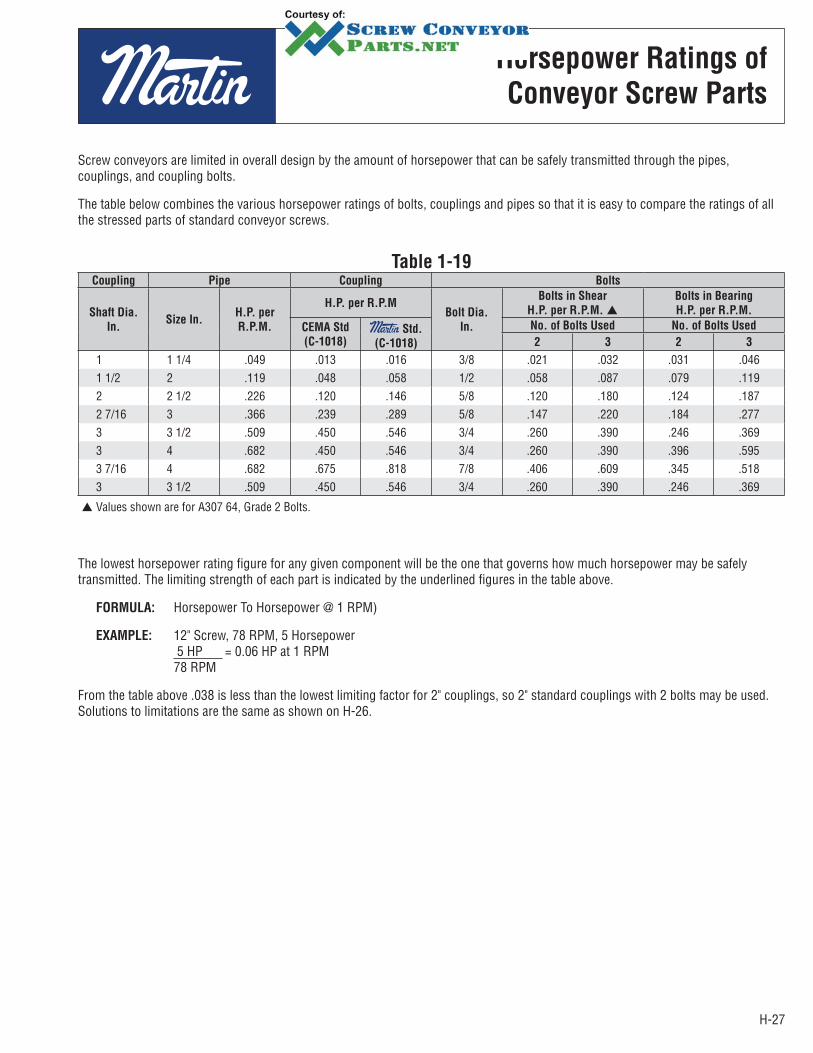
Screw conveyors are limited in overall design by the amount of horsepower that can be safely transmitted through the pipes, couplings, and coupling bolts.
The table below combines the various horsepower ratings of bolts, couplings and pipes so that it is easy to compare the ratings of all the stressed parts of standard conveyor screws.
Table 1-19Coupling Pipe Coupling Bolts
Shaft Dia.
In.Size In.
H.P. per
R.P.M.
H.P. per R.P.MBolt Dia.
In.
Bolts in Shear
H.P. per R.P.M.
Bolts in Bearing
H.P. per R.P.M.
CEMA Std
(C-1018) Std.
(C-1018)
No. of Bolts Used No. of Bolts Used
2 3 2 3
1 1 1/4 .049 .013 .016 3/8 .021 .032 .031 .0461 1/2 2 .119 .048 .058 1/2 .058 .087 .079 .1192 2 1/2 .226 .120 .146 5/8 .120 .180 .124 .1872 7/16 3 .366 .239 .289 5/8 .147 .220 .184 .2773 3 1/2 .509 .450 .546 3/4 .260 .390 .246 .3693 4 .682 .450 .546 3/4 .260 .390 .396 .5953 7/16 4 .682 .675 .818 7/8 .406 .609 .345 .5183 3 1/2 .509 .450 .546 3/4 .260 .390 .246 .369
Values shown are for A307 64, Grade 2 Bolts.
The lowest horsepower rating figure for any given component will be the one that governs how much horsepower may be safely transmitted. The limiting strength of each part is indicated by the underlined figures in the table above.
FORMULA: Horsepower To Horsepower @ 1 RPM)
EXAMPLE: 12" Screw, 78 RPM, 5 Horsepower 5 HP = 0.06 HP at 1 RPM 78 RPM
From the table above .038 is less than the lowest limiting factor for 2" couplings, so 2" standard couplings with 2 bolts may be used. Solutions to limitations are the same as shown on H-26.
H-28
Screw Conveyor End Thrust
Thermal Expansion
End thrust in a Screw Conveyor is created as a reaction to the forces required to move the material along the axis of the conveyor trough. Such a force is opposite in direction to the flow of material. A thrust bearing and sometimes reinforcement of the conveyor trough is required to resist thrust forces. Best performance can be expected if the conveyor end thrust bearing is placed so that the rotating members are in tension; therefore, an end thrust bearing should be placed at the discharge end of a conveyor. Placing an end thrust bearing assembly at the feed end of a conveyor places rotating members in compression which may have undesirable effects, but this is sometimes necessary in locating equipment.
There are several methods of absorbing thrust forces, the most popular methods are:
1. Thrust washer assembly — installed on the shaft between the pipe end and the trough end plate, or on the outside of the end bearing.
2. Type “E” end thrust assembly, which is a Double Roller Bearing and shaft assembly.
3. Screw Conveyor Drive Unit, equipped with double roller bearing thrust bearings, to carry both thrust and radial loads.
Past experience has established that component selection to withstand end thrust is rarely a critical factor and thrust is not normally calculated for design purposes. Standard conveyor thrust components will absorb thrust without resorting to special design in most applications.
Expansion of Screw Conveyors Handling Hot Materials
Screw conveyors often are employed to convey hot materials. It is therefore necessary to recognize that the conveyor will increase in length as the temperature of the trough and screw increases when the hot material begins to be conveyed.
The recommended general practice is to provide supports for the trough which will allow movement of the trough end feet during the trough expansion, and during the subsequent contraction when handling of the hot material ceases. The drive end of the conveyor usually is fixed, allowing the remainder of the trough to expand or contract. In the event there are intermediate inlets or discharge spouts that cannot move, the expansion type troughs are required.
Furthermore, the conveyor screw may expand or contract in length at different rates than the trough. Therefore, expansion hangers are generally recommended. The trough end opposite the drive should incorporate an expansion type ball or roller bearing or sleeve bearing which will safely provide sufficient movement.
The change in screw conveyor length may be determined from the following formula:
ΔL = L (t1 - t2) C
Where: ΔL = increment of change in length, inch L = overall conveyor length in inches t1 = upper limit of temperature, degrees Fahrenheit t2 = limit of temperature, degrees Fahrenheit (or lowest ambient temperature expected)
C = coefficient of linear expansion, inches per inch per degree Fahrenheit. This coefficient has the following values for various metals:a) Hot rolled carbon steel, 6.5×10⁻⁶, (.0000065)b) Stainless steel, 9.9×10⁻⁶, (.0000099)c) Aluminum, 12.8×10⁻⁶, (.0000128)
EXAMPLE: A carbon steel screw conveyor 30 feet overall length is subject to a rise in temperature of 200°F, reaching a hot metal temperature of 260°F from an original metal temperature of 60°F.
t1 = 260 t1 - t2 = 200 t2 = 60 L = (30) (12) = 360 ΔL = (360) (200) (6.5×10⁻⁶) = 0.468 inches, or about 15/32 inches.

H-29
Conveyor Screw
Deflection
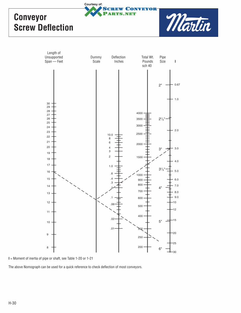
When using conveyor screws of standard length, deflection is seldom a problem. However, if longer than standard sections of screw are to be used, without intermediate hanger bearings, care should be taken to prevent the screw flights from contacting the trough because of excessive deflection. The deflection at mid span may be calculated from the following formula.
D =5WL3
384 (29,000,000) (I)
Where: D = Deflection at mid span in inches W = Total screw weight in pounds, see pages H-79 to H-84 L = Screw length in inches l = Movement of inertia of pipe or shaft, see table 1-20 or 1-21 below
Table 1-20Schedule 40 Pipe
Pipe Size 2" 2 1/2" 3" 3 1/2" 4" 5" 6" 8" 10"
I .666 1.53 3.02 4.79 7.23 15.2 28.1 72.5 161
Table 1-21Schedule 80 Pipe
Pipe Size 2" 2 1/2" 3" 3 1/2" 4" 5" 6" 8" 10"
l .868 1.92 3.89 6.28 9.61 20.7 40.5 106 212
EXAMPLE: Determine the deflection of a 12H512 screw conveyor section mounted on 3" sch 40 pipe, overall length is 16"-0'.
W = 272# L = 192" I = 3.02 (From chart above
D =5(272#)(1923)
= .29 inches384 (29,000,000) (3.02)
Applications where the calculated deflection of the screw exceeds .25 inches (1/4") should be referred to our Engineering Department for recommendations. Very often the problem of deflection can be solved by using a conveyor screw section with a larger diameter pipe or a heavier wall pipe. Usually, larger pipe sizes tend to reduce deflection more effectively than heavier wall pipe.
H-30
Conveyor
Screw Deflection
Length of Unsupported Dummy Deflection Total Wt. Pipe Span — Feet Scale Inches Pounds Size I
sch 40
I = Moment of inertia of pipe or shaft, see Table 1-20 or 1-21
The above Nomograph can be used for a quick reference to check deflection of most conveyors.
H-31
Inclined and Vertical
Screw Conveyors
Inclined
Screw
Conveyors
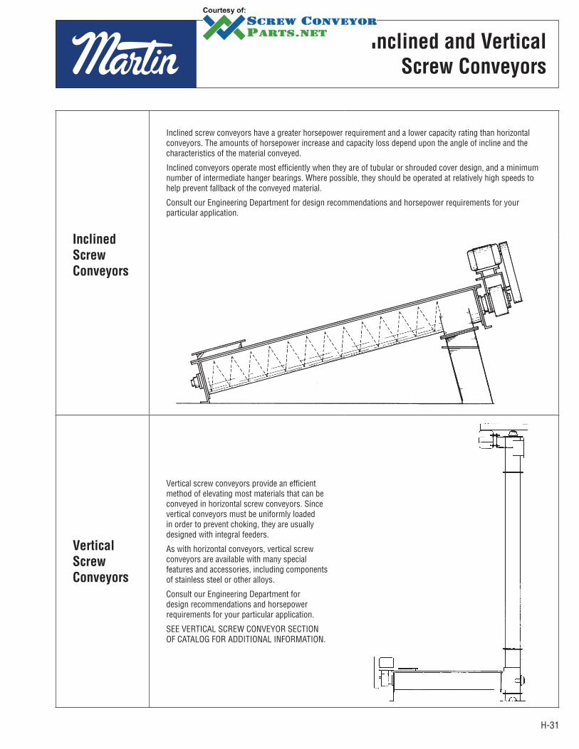
Inclined screw conveyors have a greater horsepower requirement and a lower capacity rating than horizontal conveyors. The amounts of horsepower increase and capacity loss depend upon the angle of incline and the characteristics of the material conveyed.
Inclined conveyors operate most efficiently when they are of tubular or shrouded cover design, and a minimum number of intermediate hanger bearings. Where possible, they should be operated at relatively high speeds to help prevent fallback of the conveyed material.
Consult our Engineering Department for design recommendations and horsepower requirements for your particular application.
Vertical
Screw
Conveyors
Vertical screw conveyors provide an efficient method of elevating most materials that can be conveyed in horizontal screw conveyors. Since vertical conveyors must be uniformly loaded in order to prevent choking, they are usually designed with integral feeders.
As with horizontal conveyors, vertical screw conveyors are available with many special features and accessories, including components of stainless steel or other alloys.
Consult our Engineering Department for design recommendations and horsepower requirements for your particular application.
SEE VERTICAL SCREW CONVEYOR SECTION OF CATALOG FOR ADDITIONAL INFORMATION.
H-32
Screw
Feeders
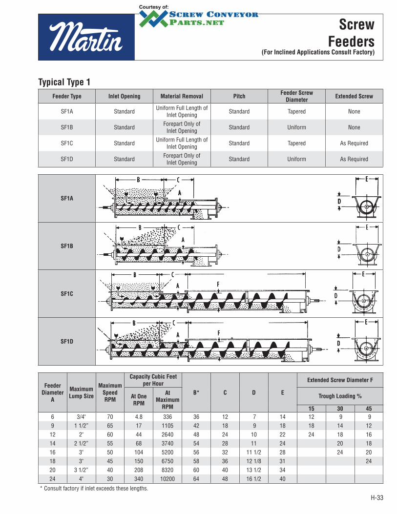
Screw Feeders are designed to regulate the rate of material flow from a hopper or bin. The inlet is usually flooded with material (95% loaded). One or more tapered or variable pitch screws convey the material at the required rate. Screw feeders are regularly provided with shrouded or curved cover plates for a short distance beyond the end of the inlet opening, to obtain feed regulation. As the pitch or diameter increases beyond the shroud the level of the material in the conveyor drops to normal loading levels. Longer shrouds, extra short pitch screws and other modifications are occasionally required to reduce flushing of very free flowing material along the feeder screw.
Feeders are made in two general types: Type 1 with regular pitch flighting and Type 2 with short pitch flighting. Both types are also available with uniform diameter and tapering diameter screws. The various combinations are shown on pages H-33 – H-34. Screw feeders with uniform screws, Types 1B, 1D, 2B, 2D are regularly used for handling fine free flowing materials. Since the diameter of the screw is uniform, the feed of the material will be from the forepart of the inlet and not across the entire length. Where hoppers, bins, tanks, etc. are to be completely emptied, or dead areas of material over the inlet are not objectionable, this type of feeder is entirely satisfactory, as well as economical. Screw feeders with tapering diameter screws will readily handle materials containing a fair percentage of lumps. In addition, they are used extensively where it is necessary or desirable to draw the material uniformly across the entire length of the inlet opening to eliminate inert or dead areas of material at the forepart of the opening. Types 1A, 1C, 2A, and 2C fall into this category. Variable pitch screws can be used in place of tapering diameter screws for some applications. They consist of screws with succeeding sectional flights increasing progressively in pitch. The portion of the screw with the smaller pitch is located under the inlet opening.
Screw feeders with extended screw conveyors are necessary when intermediate hangers are required, or when it is necessary to convey the material for some distance. A screw conveyor of larger diameter than the feeder screw is combined with the feeder to make the extension. See types 1C, 1D, 2C, 2D.
Multiple screw feeders are usually in flat bottom bins for discharging material which have a tendency to pack or bridge under pressure. Frequently, the entire bin bottom is provided with these feeders which convey the material to collecting conveyors. Such arrangements are commonly used for handling hogged fuel, wood shavings, etc.
Screw feeders are available in a variety of types to suit specific materials and applications. We recommend that you contact our Engineering Department for design information.
H-33
Screw
Feeders(For Inclined Applications Consult Factory)
Typical Type 1
Feeder Type Inlet Opening Material Removal PitchFeeder Screw
DiameterExtended Screw
SF1A Standard Uniform Full Length of Inlet Opening Standard Tapered None
SF1B Standard Forepart Only of Inlet Opening Standard Uniform None
SF1C Standard Uniform Full Length of Inlet Opening Standard Tapered As Required
SF1D Standard Forepart Only of Inlet Opening Standard Uniform As Required
SF1A
SF1B
SF1C
SF1D
Feeder
Diameter
A
Maximum
Lump Size
Maximum
Speed
RPM
Capacity Cubic Feet
per Hour
B* C D E
Extended Screw Diameter F
At One
RPM
At
Maximum
RPM
Trough Loading %
15 30 45
6 3/4" 70 4.8 336 36 12 7 14 12 9 99 1 1/2” 65 17 1105 42 18 9 18 18 14 12
12 2" 60 44 2640 48 24 10 22 24 18 1614 2 1/2” 55 68 3740 54 28 11 24 20 1816 3" 50 104 5200 56 32 11 1/2 28 24 2018 3" 45 150 6750 58 36 12 1/8 31 2420 3 1/2” 40 208 8320 60 40 13 1/2 3424 4" 30 340 10200 64 48 16 1/2 40
* Consult factory if inlet exceeds these lengths.
H-34
Screw
Feeders(For Inclined Applications Consult Factory)
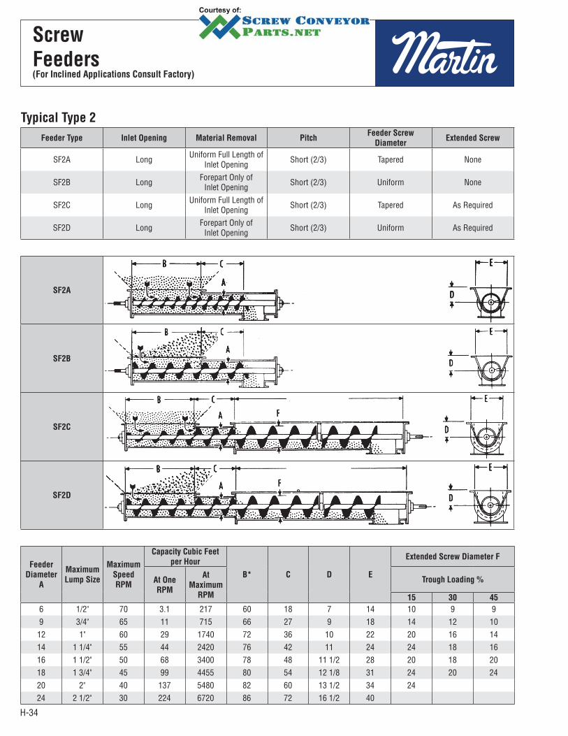
Typical Type 2
Feeder Type Inlet Opening Material Removal PitchFeeder Screw
DiameterExtended Screw
SF2A Long Uniform Full Length of Inlet Opening Short (2/3) Tapered None
SF2B Long Forepart Only of Inlet Opening Short (2/3) Uniform None
SF2C Long Uniform Full Length of Inlet Opening Short (2/3) Tapered As Required
SF2D Long Forepart Only of Inlet Opening Short (2/3) Uniform As Required
SF2A
SF2B
SF2C
SF2D
Feeder
Diameter
A
Maximum
Lump Size
Maximum
Speed
RPM
Capacity Cubic Feet
per Hour
B* C D E
Extended Screw Diameter F
At One
RPM
At
Maximum
RPM
Trough Loading %
15 30 45
6 1/2" 70 3.1 217 60 18 7 14 10 9 99 3/4" 65 11 715 66 27 9 18 14 12 10
12 1" 60 29 1740 72 36 10 22 20 16 1414 1 1/4" 55 44 2420 76 42 11 24 24 18 1616 1 1/2" 50 68 3400 78 48 11 1/2 28 20 18 2018 1 3/4" 45 99 4455 80 54 12 1/8 31 24 20 2420 2" 40 137 5480 82 60 13 1/2 34 2424 2 1/2" 30 224 6720 86 72 16 1/2 40
H-35
Design
and Layout
PAGE
CLASSIFICATION OF ENCLOSURE TYPES . . . . . . . . . . . . . . . . . . . . . . . . . . . . . . . . . . . . . . . . . . . . . . . . . . . . . . . . . . . H-36
HAND OF CONVEYORS . . . . . . . . . . . . . . . . . . . . . . . . . . . . . . . . . . . . . . . . . . . . . . . . . . . . . . . . . . . . . . . . . . . . . . . . . H-37
CLASSIFICATION OF SPECIAL CONTINUOUS WELD FINISHES . . . . . . . . . . . . . . . . . . . . . . . . . . . . . . . . . . . . . . . . . . . H-38
DETAILING OF “U" TROUGH . . . . . . . . . . . . . . . . . . . . . . . . . . . . . . . . . . . . . . . . . . . . . . . . . . . . . . . . . . . . . . . . . . . . . . H-39
DETAILING OF TUBULAR TROUGH . . . . . . . . . . . . . . . . . . . . . . . . . . . . . . . . . . . . . . . . . . . . . . . . . . . . . . . . . . . . . . . . H-40
DETAILING OF TROUGH AND DISCHARGE FLANGES . . . . . . . . . . . . . . . . . . . . . . . . . . . . . . . . . . . . . . . . . . . . . . . . . . H-41
BOLT TABLES . . . . . . . . . . . . . . . . . . . . . . . . . . . . . . . . . . . . . . . . . . . . . . . . . . . . . . . . . . . . . . . . . . . . . . . . . . . . . . . . . H-43
PIPE SIZES AND WEIGHTS . . . . . . . . . . . . . . . . . . . . . . . . . . . . . . . . . . . . . . . . . . . . . . . . . . . . . . . . . . . . . . . . . . . . . . H-45
SCREW CONVEYOR DRIVE ARRANGEMENTS . . . . . . . . . . . . . . . . . . . . . . . . . . . . . . . . . . . . . . . . . . . . . . . . . . . . . . . . H-46
STANDARDS HELICOID SCREW . . . . . . . . . . . . . . . . . . . . . . . . . . . . . . . . . . . . . . . . . . . . . . . . . . . . . . . . . . . . . . . . . . H-47
STANDARDS SECTIONAL (BUTTWELD) SCREW . . . . . . . . . . . . . . . . . . . . . . . . . . . . . . . . . . . . . . . . . . . . . . . . . . . . . . H-48
SCREW CONVEYOR SAMPLE HORSEPOWER WORKSHEET . . . . . . . . . . . . . . . . . . . . . . . . . . . . . . . . . . . . . . . . . . . . H-183
Classes of Enclosures
Conveyors can be designed to protect the material being handled from a hazardous surrounding or to protect the surroundings from a hazardous material being conveyed.
This section establishes recommended classes of construction for conveyor enclosures — without regard to their end use or application. These several classes call for specific things to be done to a standard conveyor housing to provide several degrees of enclosure protection.
Enclosure Classifications
Class IE — Class IE enclosures are those provided primarily for the protection of operating personnel or equipment, or where the enclosure forms an integral or functional part of the conveyor or structure. They are generally used where dust control is not a factor or where protection for, or against, the material being handled is not necessary — although as conveyor enclosures a certain amount or protection is afforded.
Class IIE — Class IIE enclosures employ constructions which provide some measure of protection against dust or for, or against, the material being handled.
Class IIIE — Class IIIE enclosures employ constructions which provide a higher degree of protection in these classes against dust, and for or against the material being handled.
Class IVE — Class IVE enclosures are for outdoor applications and under normal circumstances provide for the exclusion of water from the inside of the casing. They are not to be construed as being water-tight, as this may not always be the case.
When more than one method of fabrication is shown, either is acceptable.
H-36
Enclosures
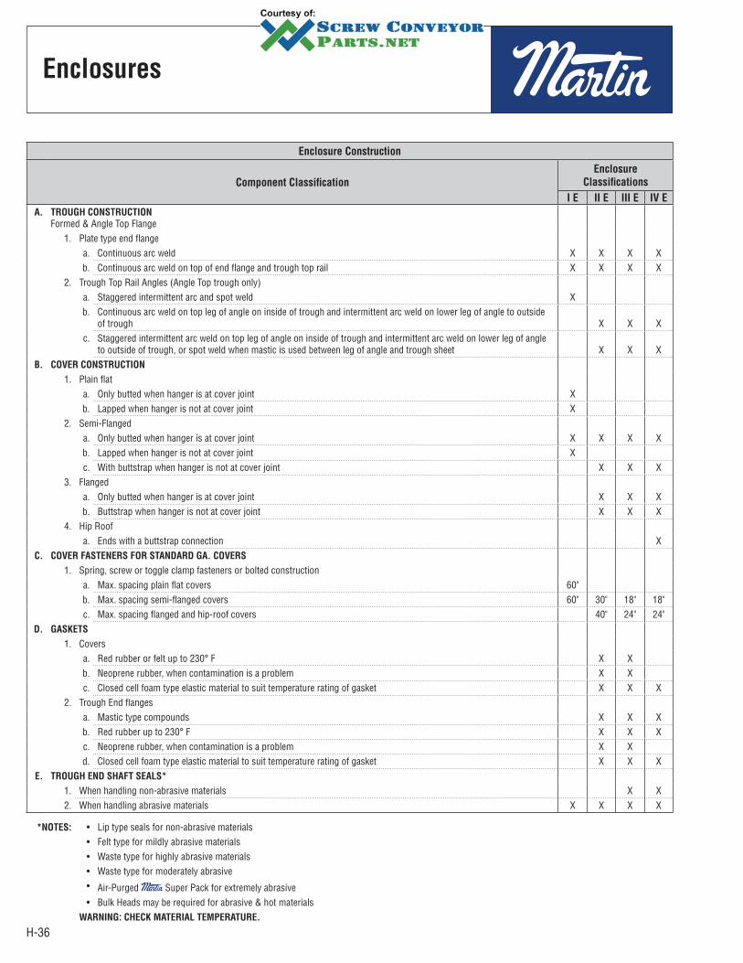
Enclosure Construction
Component Classification
Enclosure
Classifications
I E II E III E IV E
A. TROUGH CONSTRUCTION
Formed & Angle Top Flange1. Plate type end flange
a. Continuous arc weld X X X Xb. Continuous arc weld on top of end flange and trough top rail X X X X
2. Trough Top Rail Angles (Angle Top trough only)a. Staggered intermittent arc and spot weld Xb. Continuous arc weld on top leg of angle on inside of trough and intermittent arc weld on lower leg of angle to outside
of trough X X Xc. Staggered intermittent arc weld on top leg of angle on inside of trough and intermittent arc weld on lower leg of angle
to outside of trough, or spot weld when mastic is used between leg of angle and trough sheet X X XB. COVER CONSTRUCTION
1. Plain flata. Only butted when hanger is at cover joint Xb. Lapped when hanger is not at cover joint X
2. Semi-Flangeda. Only butted when hanger is at cover joint X X X Xb. Lapped when hanger is not at cover joint Xc. With buttstrap when hanger is not at cover joint X X X
3. Flangeda. Only butted when hanger is at cover joint X X Xb. Buttstrap when hanger is not at cover joint X X X
4. Hip Roofa. Ends with a buttstrap connection X
C. COVER FASTENERS FOR STANDARD GA. COVERS
1. Spring, screw or toggle clamp fasteners or bolted constructiona. Max. spacing plain flat covers 60"b. Max. spacing semi-flanged covers 60" 30" 18" 18"c. Max. spacing flanged and hip-roof covers 40" 24" 24"
D. GASKETS
1. Coversa. Red rubber or felt up to 230° F X Xb. Neoprene rubber, when contamination is a problem X Xc. Closed cell foam type elastic material to suit temperature rating of gasket X X X
2. Trough End flangesa. Mastic type compounds X X Xb. Red rubber up to 230° F X X Xc. Neoprene rubber, when contamination is a problem X Xd. Closed cell foam type elastic material to suit temperature rating of gasket X X X
E. TROUGH END SHAFT SEALS*
1. When handling non-abrasive materials X X2. When handling abrasive materials X X X X
*NOTES: • Lip type seals for non-abrasive materials• Felt type for mildly abrasive materials• Waste type for highly abrasive materials• Waste type for moderately abrasive• Air-Purged Super Pack for extremely abrasive• Bulk Heads may be required for abrasive & hot materials
WARNING: CHECK MATERIAL TEMPERATURE.
H-37
Hand
Conveyors
Left Hand
Flow
Left Hand
C.W.
Rotation
C.C.W.
Rotation
Flow
Right Hand
Right Hand
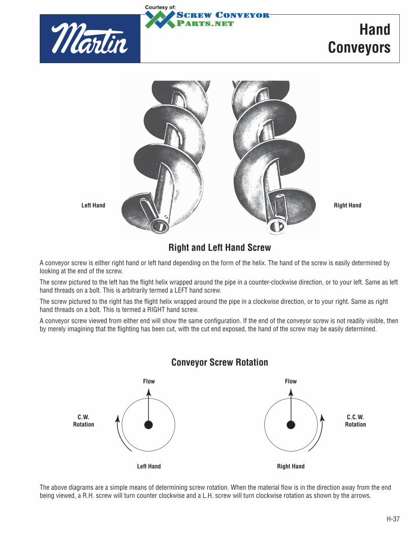
Right and Left Hand Screw
Conveyor Screw Rotation
A conveyor screw is either right hand or left hand depending on the form of the helix. The hand of the screw is easily determined by looking at the end of the screw.
The screw pictured to the left has the flight helix wrapped around the pipe in a counter-clockwise direction, or to your left. Same as left hand threads on a bolt. This is arbitrarily termed a LEFT hand screw.
The screw pictured to the right has the flight helix wrapped around the pipe in a clockwise direction, or to your right. Same as right hand threads on a bolt. This is termed a RIGHT hand screw.
A conveyor screw viewed from either end will show the same configuration. If the end of the conveyor screw is not readily visible, then by merely imagining that the flighting has been cut, with the cut end exposed, the hand of the screw may be easily determined.
The above diagrams are a simple means of determining screw rotation. When the material flow is in the direction away from the end being viewed, a R.H. screw will turn counter clockwise and a L.H. screw will turn clockwise rotation as shown by the arrows.
H-38
Conveyor Screw
Rotation
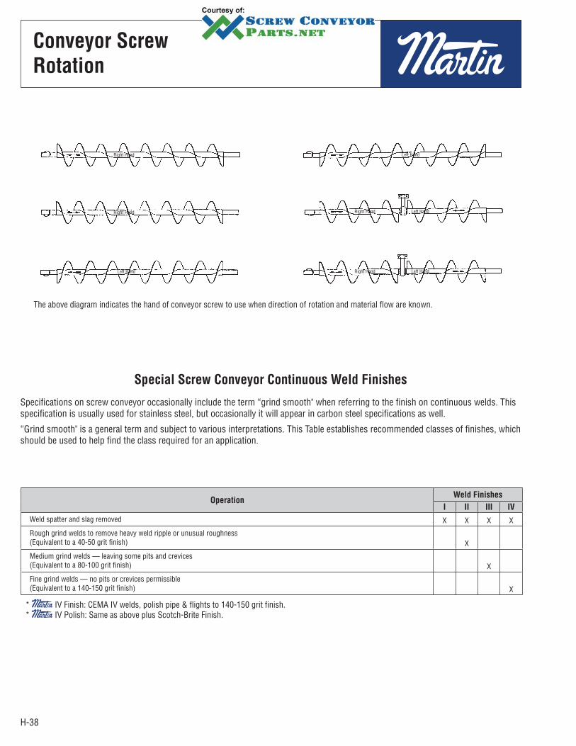
Right Hand Left Hand
Right Hand Right Hand
Right Hand
Left Hand
Left HandLeft Hand
The above diagram indicates the hand of conveyor screw to use when direction of rotation and material flow are known.
Special Screw Conveyor Continuous Weld Finishes
Specifications on screw conveyor occasionally include the term “grind smooth" when referring to the finish on continuous welds. This specification is usually used for stainless steel, but occasionally it will appear in carbon steel specifications as well.
“Grind smooth" is a general term and subject to various interpretations. This Table establishes recommended classes of finishes, which should be used to help find the class required for an application.
OperationWeld Finishes
I II III IV
Weld spatter and slag removed X X X X
Rough grind welds to remove heavy weld ripple or unusual roughness(Equivalent to a 40-50 grit finish) X
Medium grind welds — leaving some pits and crevices(Equivalent to a 80-100 grit finish) X
Fine grind welds — no pits or crevices permissible(Equivalent to a 140-150 grit finish) X
* IV Finish: CEMA IV welds, polish pipe & flights to 140-150 grit finish.* IV Polish: Same as above plus Scotch-Brite Finish.
H-39
Hand
Conveyors
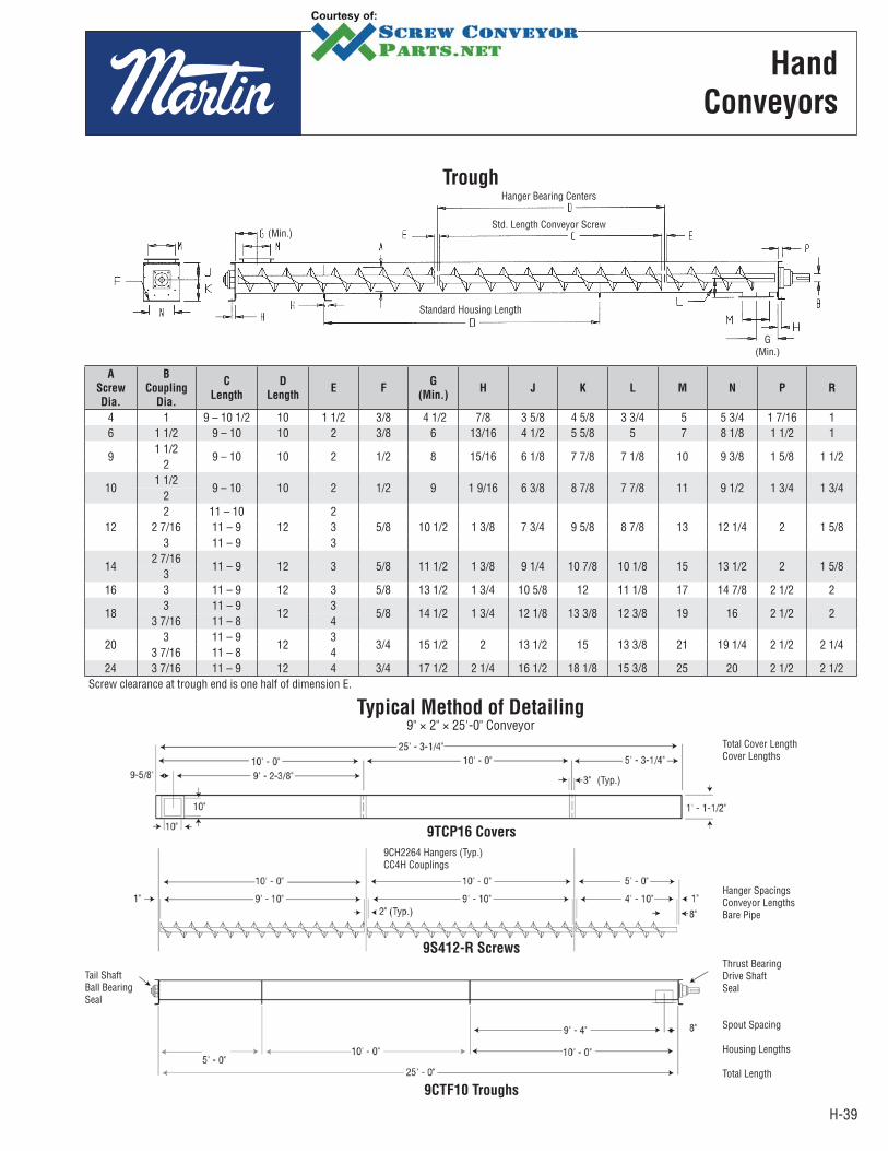
Trough
(Min.)
Standard Housing Length
Hanger Bearing Centers
Std. Length Conveyor Screw
G(Min.)
A
Screw
Dia.
B
Coupling
Dia.
C
Length
D
LengthE F
G
(Min.)H J K L M N P R
4 1 9 – 10 1/2 10 1 1/2 3/8 4 1/2 7/8 3 5/8 4 5/8 3 3/4 5 5 3/4 1 7/16 16 1 1/2 9 – 10 10 2 3/8 6 13/16 4 1/2 5 5/8 5 7 8 1/8 1 1/2 1
91 1/2
9 – 10 10 2 1/2 8 15/16 6 1/8 7 7/8 7 1/8 10 9 3/8 1 5/8 1 1/22
101 1/2
9 – 10 10 2 1/2 9 1 9/16 6 3/8 8 7/8 7 7/8 11 9 1/2 1 3/4 1 3/42
122 11 – 10
122
5/8 10 1/2 1 3/8 7 3/4 9 5/8 8 7/8 13 12 1/4 2 1 5/82 7/16 11 – 9 33 11 – 9 3
142 7/16
11 – 9 12 3 5/8 11 1/2 1 3/8 9 1/4 10 7/8 10 1/8 15 13 1/2 2 1 5/83
16 3 11 – 9 12 3 5/8 13 1/2 1 3/4 10 5/8 12 11 1/8 17 14 7/8 2 1/2 2
183 11 – 9
123
5/8 14 1/2 1 3/4 12 1/8 13 3/8 12 3/8 19 16 2 1/2 23 7/16 11 – 8 4
203 11 – 9
123
3/4 15 1/2 2 13 1/2 15 13 3/8 21 19 1/4 2 1/2 2 1/43 7/16 11 – 8 4
24 3 7/16 11 – 9 12 4 3/4 17 1/2 2 1/4 16 1/2 18 1/8 15 3/8 25 20 2 1/2 2 1/2Screw clearance at trough end is one half of dimension E.
Typical Method of Detailing9" × 2" × 25'-0" Conveyor
Tail ShaftBall BearingSeal
(Typ.)
9CH2264 Hangers (Typ.)CC4H Couplings
9TCP16 Covers
9S412-R Screws
9CTF10 Troughs
Total Cover LengthCover Lengths
Hanger SpacingsConveyor LengthsBare Pipe
Thrust BearingDrive ShaftSeal
Spout Spacing
Housing Lengths
Total Length

H-40
Layout
Typical Method of Detailing9" × 2" × 25'-0" Conveyor
(Min.) (Bare Pipe)
Standard Housing Length
Std. Length Conveyor Screw Hanger Bearing Centers
(Min.)
A
Screw
Dia.
B
Coupling
Dia.
C
Length
D
LengthE F
G
(Min.)H K L M N P R
4 1 9 – 10 1/2 10 1 1/2 3/8 4 1/2 7/8 4 5/8 3 3/4 5 5 3/4 1 7/16 1 6 1 1/2 9 – 10 10 2 3/8 6 13/16 5 5/8 5 7 8 1/8 1 1/2 1
91 1/2 9 – 10
10 2 1/2 8 1 5/16 7 7/8 7 1/8 10 9 3/8 1 5/8 1 1/22 9 – 10
101 1/2 9 – 10
10 2 1/2 9 1 9/16 8 7/8 7 7/8 11 9 1/2 1 3/4 1 3/42 9 – 10
122 11 – 10
122
5/8 10 1/2 1 3/8 9 5/8 8 7/8 13 12 1/4 2 1 5/82 7/16 11 – 9 33 11 – 9 3
142 7/16 11 – 9
12 3 5/8 11 1/2 1 3/8 10 7/8 10 1/8 15 13 1/2 2 1 5/83 11 – 9
16 3 11 – 9 12 3 5/8 13 1/2 1 3/4 12 11 1/8 17 14 7/8 2 1/2 2
183 11 – 9
123 5/8 14 1/2 1 3/4 13 3/8 12 3/8 19 16 2 1/2 2
3 7/16 11 – 8 4 3/4 15 1/2 2 15 13 3/8 21 19 1/4 2 1/2 2 1/4
203 11 – 9
123
3/4 15 1/2 2 15 13 3/8 21 19 1/4 2 1/2 2 1/43 7/16 11 8 4
24 3 7/16 11 8 12 4 3/4 17 1/2 2 1/4 18 1/8 15 3/8 25 20 2 1/2 2 1/2Screw clearance at trough end is one half of dimension E.
Tail ShaftBall BearingSeal
9TCP16 Covers
9S412-R Screws
9S412-R Screws
9CTF10 Troughs
Hanger Spacings
Conveyor LengthsBare Pipe
Thrust BearingDrive ShaftSeal
Spout Spacing
Housing Lengths
Total Length
Tubular Housing
H-41
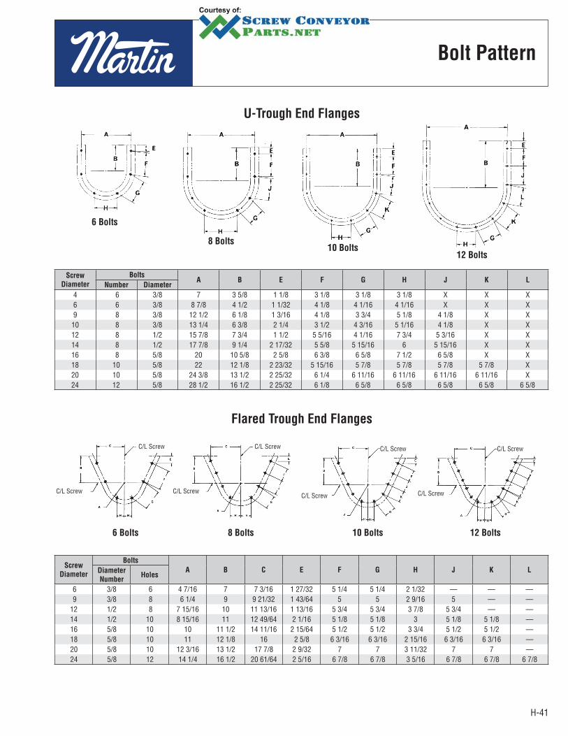
Bolt Pattern
Screw
Diameter
BoltsA B E F G H J K L
Number Diameter
4 6 3/8 7 3 5/8 1 1/8 3 1/8 3 1/8 3 1/8 X X X6 6 3/8 8 7/8 4 1/2 1 1/32 4 1/8 4 1/16 4 1/16 X X X9 8 3/8 12 1/2 6 1/8 1 3/16 4 1/8 3 3/4 5 1/8 4 1/8 X X
10 8 3/8 13 1/4 6 3/8 2 1/4 3 1/2 4 3/16 5 1/16 4 1/8 X X12 8 1/2 15 7/8 7 3/4 1 1/2 5 5/16 4 1/16 7 3/4 5 3/16 X X14 8 1/2 17 7/8 9 1/4 2 17/32 5 5/8 5 15/16 6 5 15/16 X X16 8 5/8 20 10 5/8 2 5/8 6 3/8 6 5/8 7 1/2 6 5/8 X X18 10 5/8 22 12 1/8 2 23/32 5 15/16 5 7/8 5 7/8 5 7/8 5 7/8 X20 10 5/8 24 3/8 13 1/2 2 25/32 6 1/4 6 11/16 6 11/16 6 11/16 6 11/16 X24 12 5/8 28 1/2 16 1/2 2 25/32 6 1/8 6 5/8 6 5/8 6 5/8 6 5/8 6 5/8
Screw
Diameter
Bolts
A B C E F G H J K LDiameter
NumberHoles
6 3/8 6 4 7/16 7 7 3/16 1 27/32 5 1/4 5 1/4 2 1/32 — — — 9 3/8 8 6 1/4 9 9 21/32 1 43/64 5 5 2 9/16 5 — —12 1/2 8 7 15/16 10 11 13/16 1 13/16 5 3/4 5 3/4 3 7/8 5 3/4 — —14 1/2 10 8 15/16 11 12 49/64 2 1/16 5 1/8 5 1/8 3 5 1/8 5 1/8 —16 5/8 10 10 11 1/2 14 11/16 2 15/64 5 1/2 5 1/2 3 3/4 5 1/2 5 1/2 —18 5/8 10 11 12 1/8 16 2 5/8 6 3/16 6 3/16 2 15/16 6 3/16 6 3/16 —20 5/8 10 12 3/16 13 1/2 17 7/8 2 9/32 7 7 3 11/32 7 7 —24 5/8 12 14 1/4 16 1/2 20 61/64 2 5/16 6 7/8 6 7/8 3 5/16 6 7/8 6 7/8 6 7/8
U-Trough End Flanges
Flared Trough End Flanges
6 Bolts
8 Bolts10 Bolts
12 Bolts
C/L Screw
C/L Screw
C/L Screw
C/L Screw
C/L Screw
C/L Screw
C/L Screw
C/L Screw
6 Bolts 8 Bolts 10 Bolts 12 Bolts
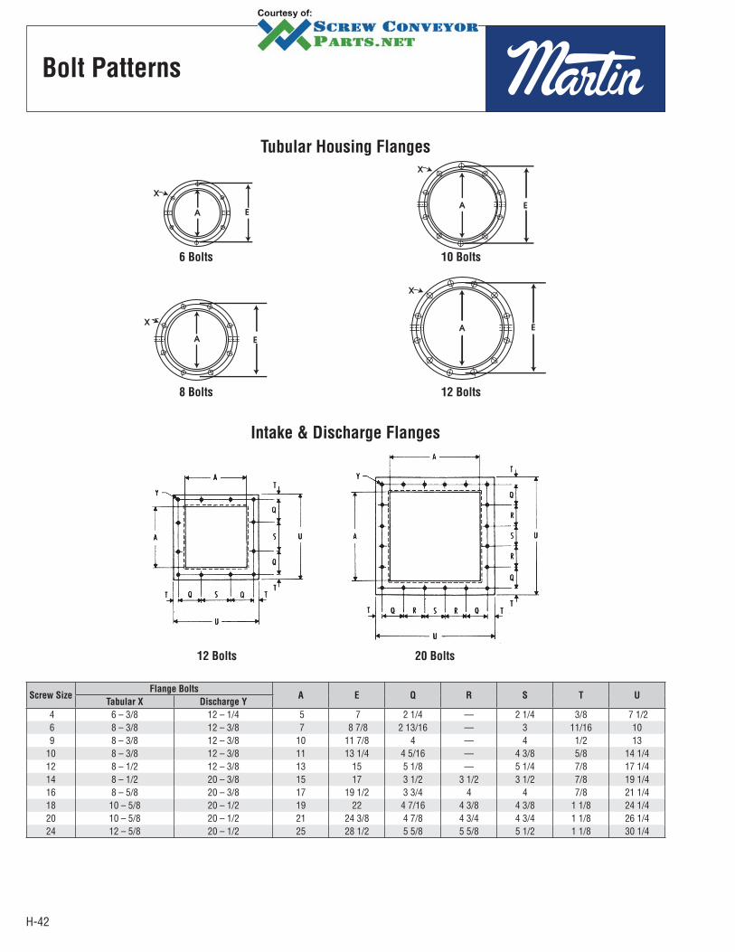
H-42
Bolt Patterns
Tubular Housing Flanges
6 Bolts
8 Bolts
10 Bolts
12 Bolts
Intake & Discharge Flanges
12 Bolts 20 Bolts
Screw SizeFlange Bolts
A E Q R S T UTabular X Discharge Y
4 6 – 3/8 12 – 1/4 5 7 2 1/4 — 2 1/4 3/8 7 1/2 6 8 – 3/8 12 – 3/8 7 8 7/8 2 13/16 — 3 11/16 10 9 8 – 3/8 12 – 3/8 10 11 7/8 4 — 4 1/2 1310 8 – 3/8 12 – 3/8 11 13 1/4 4 5/16 — 4 3/8 5/8 14 1/412 8 – 1/2 12 – 3/8 13 15 5 1/8 — 5 1/4 7/8 17 1/414 8 – 1/2 20 – 3/8 15 17 3 1/2 3 1/2 3 1/2 7/8 19 1/416 8 – 5/8 20 – 3/8 17 19 1/2 3 3/4 4 4 7/8 21 1/418 10 – 5/8 20 – 1/2 19 22 4 7/16 4 3/8 4 3/8 1 1/8 24 1/420 10 – 5/8 20 – 1/2 21 24 3/8 4 7/8 4 3/4 4 3/4 1 1/8 26 1/424 12 – 5/8 20 – 1/2 25 28 1/2 5 5/8 5 5/8 5 1/2 1 1/8 30 1/4
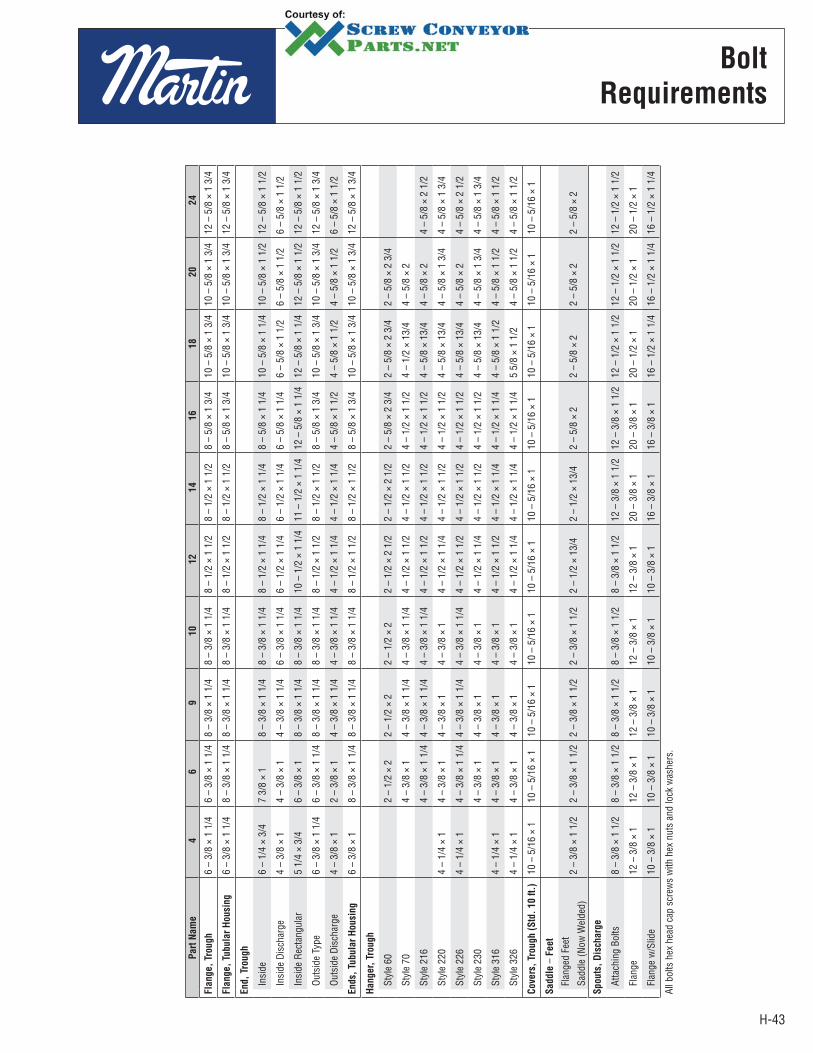
H-43
Bolt
Requirements
Part
Nam
e4
69
10
12
14
16
18
20
24
Fla
nge,
Trough
6 –
3/8
× 1
1/4
6 –
3/8
× 1
1/4
8 –
3/8
× 1
1/4
8 –
3/8
× 1
1/4
8 –
1/2
× 1
1/2
8 –
1/2
× 1
1/2
8 –
5/8
× 1
3/4
10 –
5/8
× 1
3/4
10 –
5/8
× 1
3/4
12
– 5
/8 ×
1 3
/4
Fla
nge,
Tubula
r H
ousi
ng
6 –
3/8
× 1
1/4
8 –
3/8
× 1
1/4
8 –
3/8
× 1
1/4
8 –
3/8
× 1
1/4
8 –
1/2
× 1
1/2
8 –
1/2
× 1
1/2
8 –
5/8
× 1
3/4
10 –
5/8
× 1
3/4
10
– 5
/8 ×
1 3
/4
12 –
5/8
× 1
3/4
End,
Trough
Insi
de6
– 1/
4 ×
3/4
7 3/
8 ×
1 8
– 3/
8 ×
1 1/
4 8
– 3/
8 ×
1 1/
4 8
– 1/
2 ×
1 1/
4 8
– 1/
2 ×
1 1/
4 8
– 5/
8 ×
1 1/
4 10
– 5
/8 ×
1 1
/4
10 –
5/8
× 1
1/2
12
– 5
/8 ×
1 1
/2
Insi
de D
isch
arge
4 –
3/8
× 1
4 –
3/8
× 1
4 –
3/8
× 1
1/4
6 –
3/8
× 1
1/4
6 –
1/2
× 1
1/4
6 –
1/2
× 1
1/4
6 –
5/8
× 1
1/4
6 –
5/8
× 1
1/2
6 –
5/8
× 1
1/2
6 –
5/8
× 1
1/2
Insi
de R
ecta
ngul
ar5
1/4
× 3/
4 6
– 3/
8 ×
1 8
– 3/
8 ×
1 1/
4 8
– 3/
8 ×
1 1/
4 10
– 1
/2 ×
1 1
/4
11 –
1/2
× 1
1/4
12
– 5
/8 ×
1 1
/4
12 –
5/8
× 1
1/4
12
– 5
/8 ×
1 1
/2
12 –
5/8
× 1
1/2
Outs
ide
Type
6 –
3/8
× 1
1/4
6 –
3/8
× 1
1/4
8 –
3/8
× 1
1/4
8 –
3/8
× 1
1/4
8 –
1/2
× 1
1/2
8 –
1/2
× 1
1/2
8 –
5/8
× 1
3/4
10 –
5/8
× 1
3/4
10
– 5
/8 ×
1 3
/4
12 –
5/8
× 1
3/4
Outs
ide
Disc
harg
e4
– 3/
8 ×
1 2
– 3/
8 ×
1 4
– 3/
8 ×
1 1/
4 4
– 3/
8 ×
1 1/
4 4
– 1/
2 ×
1 1/
4 4
– 1/
2 ×
1 1/
4 4
– 5/
8 ×
1 1/
2 4
– 5/
8 ×
1 1/
2 4
– 5/
8 ×
1 1/
2 6
– 5/
8 ×
1 1/
2
Ends,
Tubula
r H
ousi
ng
6 –
3/8
× 1
8 –
3/8
× 1
1/4
8 –
3/8
× 1
1/4
8 –
3/8
× 1
1/4
8 –
1/2
× 1
1/2
8 –
1/2
× 1
1/2
8 –
5/8
× 1
3/4
10 –
5/8
× 1
3/4
10
– 5
/8 ×
1 3
/4
12 –
5/8
× 1
3/4
Hanger,
Tro
ugh
Styl
e 60
2 –
1/2
× 2
2 –
1/2
× 2
2 –
1/2
× 2
2 –
1/2
× 2
1/2
2 –
1/2
× 2
1/2
2 –
5/8
× 2
3/4
2 –
5/8
× 2
3/4
2 –
5/8
× 2
3/4
Styl
e 70
4 –
3/8
× 1
4 –
3/8
× 1
1/4
4 –
3/8
× 1
1/4
4 –
1/2
× 1
1/2
4 –
1/2
× 1
1/2
4 –
1/2
× 1
1/2
4 –
1/2
× 13
/4
4 –
5/8
× 2
Styl
e 21
64
– 3/
8 ×
1 1/
4 4
– 3/
8 ×
1 1/
4 4
– 3/
8 ×
1 1/
4 4
– 1/
2 ×
1 1/
2 4
– 1/
2 ×
1 1/
2 4
– 1/
2 ×
1 1/
2 4
– 5/
8 ×
13/4
4
– 5/
8 ×
2 4
– 5/
8 ×
2 1/
2
Styl
e 22
04
– 1/
4 ×
1 4
– 3/
8 ×
1 4
– 3/
8 ×
1 4
– 3/
8 ×
1 4
– 1/
2 ×
1 1/
4 4
– 1/
2 ×
1 1/
2 4
– 1/
2 ×
1 1/
2 4
– 5/
8 ×
13/4
4
– 5/
8 ×
1 3/
4 4
– 5/
8 ×
1 3/
4
Styl
e 22
64
– 1/
4 ×
1 4
– 3/
8 ×
1 1/
4 4
– 3/
8 ×
1 1/
4 4
– 3/
8 ×
1 1/
4 4
– 1/
2 ×
1 1/
2 4
– 1/
2 ×
1 1/
2 4
– 1/
2 ×
1 1/
2 4
– 5/
8 ×
13/4
4
– 5/
8 ×
2 4
– 5/
8 ×
2 1/
2
Styl
e 23
04
– 3/
8 ×
1 4
– 3/
8 ×
1 4
– 3/
8 ×
1 4
– 1/
2 ×
1 1/
4 4
– 1/
2 ×
1 1/
2 4
– 1/
2 ×
1 1/
2 4
– 5/
8 ×
13/4
4
– 5/
8 ×
1 3/
4 4
– 5/
8 ×
1 3/
4
Styl
e 31
64
– 1/
4 ×
1 4
– 3/
8 ×
1 4
– 3/
8 ×
1 4
– 3/
8 ×
1 4
– 1/
2 ×
1 1/
2 4
– 1/
2 ×
1 1/
4 4
– 1/
2 ×
1 1/
4 4
– 5/
8 ×
1 1/
2 4
– 5/
8 ×
1 1/
2 4
– 5/
8 ×
1 1/
2
Styl
e 32
64
– 1/
4 ×
1 4
– 3/
8 ×
1 4
– 3/
8 ×
1 4
– 3/
8 ×
1 4
– 1/
2 ×
1 1/
4 4
– 1/
2 ×
1 1/
4 4
– 1/
2 ×
1 1/
4 5
5/8
× 1
1/2
4 –
5/8
× 1
1/2
4 –
5/8
× 1
1/2
Cove
rs,
Trough (
Std
. 10 f
t.)
10 –
5/1
6 ×
1 10
– 5
/16
× 1
10 –
5/1
6 ×
1 10
– 5
/16
× 1
10 –
5/1
6 ×
1 10
– 5
/16
× 1
10 –
5/1
6 ×
1 10
– 5
/16
× 1
10 –
5/1
6 ×
1 10
– 5
/16
× 1
Saddle
– F
eet
Flan
ged
Feet
Sadd
le (N
ow W
elde
d)2
– 3/
8 ×
1 1/
2 2
– 3/
8 ×
1 1/
2 2
– 3/
8 ×
1 1/
2 2
– 3/
8 ×
1 1/
2 2
– 1/
2 ×
13/4
2
– 1/
2 ×
13/4
2
– 5/
8 ×
2 2
– 5/
8 ×
2 2
– 5/
8 ×
2 2
– 5/
8 ×
2
Spouts
, D
isch
arg
e
Atta
chin
g Bo
lts8
– 3/
8 ×
1 1/
2 8
– 3/
8 ×
1 1/
2 8
– 3/
8 ×
1 1/
2 8
– 3/
8 ×
1 1/
2 8
– 3/
8 ×
1 1/
2 12
– 3
/8 ×
1 1
/2
12 –
3/8
× 1
1/2
12
– 1
/2 ×
1 1
/2
12 –
1/2
× 1
1/2
12
– 1
/2 ×
1 1
/2
Flan
ge12
– 3
/8 ×
1
12 –
3/8
× 1
12
– 3
/8 ×
1
12 –
3/8
× 1
12
– 3
/8 ×
1
20 –
3/8
× 1
20
– 3
/8 ×
1
20 –
1/2
× 1
20
– 1
/2 ×
1
20 –
1/2
× 1
Flan
ge w
/Slid
e10
– 3
/8 ×
1
10 –
3/8
× 1
10
– 3
/8 ×
1
10 –
3/8
× 1
10
– 3
/8 ×
1
16 –
3/8
× 1
16
– 3
/8 ×
1
16 –
1/2
× 1
1/4
16
– 1
/2 ×
1 1
/4
16 –
1/2
× 1
1/4
All b
olts
hex
hea
d ca
p sc
rew
s w
ith h
ex n
uts
and
lock
was
hers
.

H-44
Bolt
Requirements
Part Name 1 1 1/2 2 2 7/16 3 3 7/16
Bearings, End
Discharge Bronze 3 – 3/8 × 1 1/4 3 – 1/2 × 1 1/2 3 – 5/8 × 1 3/4 3 – 5/8 × 1 3/4 3 – 3/4 × 2 3 – 3/4 × 2 1/4
Discharge Ball 3 – 3/8 × 1 1/4 3 – 1/2 × 1 1/2 3 – 5/8 × 1 1/2 3 – 5/8 × 13/4 3 – 3/4 × 2 3 – 3/4 × 2 1/4
Flanged Bronze 4 – 3/8 × 1 1/4 4 – 1/2 × 1 1/2 4 – 5/8 × 1 3/4 4 – 5/8 × 13/4 4 – 3/4 × 2 4 – 3/4 × 2 1/4
Flanged Ball 4 – 3/8 × 1 1/4 4 – 1/2 × 1 1/2 4 – 5/8 × 1 3/4 4 – 5/8 × 13/4 4 – 3/4 × 2 1/2 4 – 3/4 × 2 3/4
Flanged Roller 4 – 1/2 × 2 1/2 4 – 1/2 × 2 1/2 4 – 5/8 × 3 4 – 3/4× 3 4 – 3/4 × 3 1/4
Pillow Block Bronze 2 – 3/8 × 1 1/2 2 – 1/2 × 1 3/4 2 – 5/8 × 2 2 – 5/8 × 21/4 2 – 3/4 × 2 1/2 2 – 7/8 × 2 3/4
Pillow Block Ball 2 – 3/8 × 1 3/4 2 – 1/2 × 2 1/4 2 – 5/8 × 2 1/2 2 – 5/8 × 23/4 2 – 7/8 × 3 1/2 2 – 7/8 × 3 3/4
Pillow Block, Roller 2 – 1/2 × 2 1/4 2 – 5/8 × 2 1/2 2 – 5/8 × 23/4 2 – 3/4 × 3 2 – 7/8 × 3 1/2
Bearings, Thrust
Type “E" Roller 4 – 1/2 × 2 3/4 4 – 1/2 ×2 3/4 4 – 5/8 × 3 1/4 4 – 3/4 × 3 1/2 4 – 3/4 × 3 3/4
Coupling Bolts 3/8 × 2 1/16 1/2 × 3 5/8 × 3 5/8 5/8 × 4 3/8 3/4 × 5 – 3" Pipe3/4 × 5 1/2 – 4" Pipe 7/8 × 5 1/2
Seals, Shafts
Flanged Gland 4 – 1/2 × 1 1/2 4 – 5/8 × 1 1/2 4 – 5/8 × 1 1/2 4 – 3/4 × 1 3/4 4 – 3/4 × 1 3/4
Plate w/Ball or Bronze 4 – 1/2 × 2 4 – 5/8 × 2 1/4 4 – 5/8 × 2 1/4 4 – 3/4 × 3 4 – 3/4 × 3 1/2
Plate w/Roller 4 – 1/2 × 3 4 1/2 × 3 4 – 5/8 × 3 1/2 4 – 3/4 × 3 1/2 4 – 3/4 × 4
Split Gland 2 – 1/2 × 1 1/2 2 – 1/2 × 1 1/2 2 – 5/8 × 1 3/4 2 – 5/8 × 1 3/4 2 – 3/4 × 2 1/4
Waste Pack, w/Ball or Bronze 4 – 1/2 × 3 1/2 4 – 5/8 × 3 1/2 4 – 5/8 × 4 4 – 3/4 × 4 4 – 3/4 × 5
Waste Pack, w/Roller 4 – 1/2 × 4 4 – 1/2 × 4 4 – 5/8 × 4 1/2 4 – 3/4 × 5 4 – 3/4 × 5 1/2
All other bolts hex head cap screws with hex nuts and lock washers.

H-45
Pipe Sizes, Dimensions
and Weights
Nominal
Pipe Size
Outside
DiameterI.P.S Schedule Wall
Inside
Diameter
Wt./Ft.
(lb)
1/8 .405
10S .049 .307 .1863 40 40S Standard .068 .269 .244780 80S Extra Heavy .095 .215 .3145
1/4 .540
10S .065 .410 .3297 40 40S Standard .088 .364 .424880 80S Extra Heavy .119 .302 .5351
3/8 .67510S .065 .545 .4235
40 40S Standard .091 .493 .5676 80 80S Extra Heavy .126 .423 .7388
1/2 .840
5S .065 .710 .538310S .083 .674 .6710
40 40S Standard .109 .622 .8510 80 80S Extra Heavy .147 .546 1.088160 .187 .466 1.304
XX Heavy .294 .252 1.714
3/4 1.050
5S .065 .920 .6838 10S .083 .884 .8572
40 40S Standard .113 .824 1.13180 80S Extra Heavy .154 .742 1.474160 .218 .614 1.937
XX Heavy .308 .434 2.441
1 1.315
5S .065 1.185 .867810S .109 1.097 1.404
40 40S Standard .133 1.049 1.679 80 80S Extra Heavy .179 .957 2.172 160 .250 .815 2.844
XX Heavy .358 .599 3.659
1 1/4 1.660
5S .065 1.530 1.107 10S .109 1.442 1.806
40 40S Standard .140 1.380 2.27380 80S Extra Heavy .191 1.278 2.997160 .250 1.160 3.765
XX Heavy .382 .896 5.214
1 1/2 1.900
5S .065 1.770 1.274 10S .109 1.682 2.085
40 40S Standard .145 1.610 2.71880 80S Extra Heavy .200 1.500 3.631160 .281 1.338 4.859
XX Heavy .400 1.100 6.408
2 2.375
5S .065 2.245 1.60410S .109 2.157 2.638
40 40S Standard .154 2.067 3.65380 80S Extra Heavy .218 1.939 5.022160 .343 1.689 7.444
XX Heavy .436 1.503 9.029
2 1/2 2.875
5S .083 2.709 2.475 10S .120 2.635 3.53140 40S Standard .203 2.469 5.79380 80S Extra Heavy .276 2.323 7.661160 .375 2.125 10.01
XX Heavy .552 1.771 13.69
Nominal
Pipe Size
Outside
DiameterI.P.S Schedule Wall
Inside
Diameter
Wt./Ft.
(lb)
3 3.500
5S .083 3.334 3.02910S .120 3.260 4.332
40 40S Standard .216 3.068 7.57680 80S Extra Heavy .300 2.900 10.25160 .438 2.624 14.32
XX Heavy .600 2.300 18.58
3 1/2 4.000
5S .083 3.834 3.47210S .120 3.760 4.973
40 40S Standard .226 3.548 9.10980 80S Extra Heavy .318 3.364 12.50
4 4.500
5S .083 4.334 3.91510S .120 4.260 5.613
40 40S Standard .237 4.026 10.7980 80S Extra Heavy .337 3.826 14.98120 .438 3.624 19.00160 .531 3.438 22.51
XX Heavy .674 3.152 27.54
5 5.563
5S .109 5.345 6.34910S .134 5.295 7.770
40 40S Standard .258 5.047 14.6280 80S Extra Heavy .375 4.813 20.78120 .500 4.563 27.04160 .625 4.313 32.96
XX Heavy .750 4.063 38.55
6 6.625
5S .109 6.407 7.58510S .134 6.357 9.289
40 40S Standard .280 6.065 18.9780 80S Extra Heavy .432 5.761 28.57120 .562 5.491 36.39160 .718 5.189 45.30
XX Heavy .864 4.897 53.16
8 8.625
5S .109 8.407 9.91410S .148 8.329 13.40
20 .250 8.125 22.3630 .277 8.071 24.7040 40S Standard .322 7.981 28.5560 .406 7.813 35.6480 80S Extra Heavy .500 7.625 43.39100 .593 7.439 50.87120 .718 7.189 60.63140 .812 7.001 67.76
XX Heavy .875 6.875 72.42160 .906 6.813 74.69
10 10.750
5S .134 10.482 15.1910S .165 10.420 18.70
20 .250 10.250 28.0430 .307 10.136 34.2440 40S Standard .365 10.020 40.4860 80S Extra Heavy .500 9.750 54.7480 .593 9.564 64.33100 .718 9.224 76.93120 .843 9.064 89.20140 1.000 8.750 104.1160 1.125 8.500 115.7
NOTE: Weights shown are in pounds per foot, based on the average wall of the pipe. The following formula was used in calculating the weight per foot.
W = 10.68 (D — t)tW = Weight in pounds per foot (to 4 digits)D = Outside Diameter in inches (to 3 decimal places)t = Wall thickness in decimals (to 3 decimal places)
All weights are carried to four digits only, the fifth digit being carried forward if five or over, or dropped if under five.

H-46
Typical Drive
Arrangements
The most common types of drives for Screw Conveyors are illustrated below.
In addition to those shown, other types available are: variable speed drives, hydraulic drives, and take-off drives for connection to other equipment.
For special drive requirements, consult our Engineering Department.
SCREW
DRIVER
REDUCER
(Side View)
Reducer mounts on trough end, and is directly connected to the conveyor screw and includes integral thrust bearing, seal gland, and drive shaft. Motor mount may be positioned at top, either side, or below. Separate drive shaft, end bearing, and seal are not required.
SHAFT
MOUNTED
REDUCER
(End View)
Reducer mounts on conveyor drive shaft. Motor and “V"-Belt drive may be in any convenient location. The torque arm may be fastened to the floor, or fitted to trough end. Requires extended drive shaft, end bearing, and seal.
Note: Requires thrust unit or collars to hold thrust.
GEARMOTOR
DRIVE
(Side View)
Integral motor-reducer with chain drive to conveyor drive shaft. Usually mounted to top of trough by means of an adapter plate.
BASE TYPE
REDUCER
DRIVE
(Top View)
Motor direct-coupled to base type reducer, with chain drive to conveyor drive shaft. Usually mounted on floor or platform as close as possible to conveyor.

H-47
CEMA
Standards
Cut Flight / Cut & Folded Flight Conveyors
Helicoid Screw ConveyorsB
Thickness at Edges
DBore
HBolt hole
ADiameterTolerance
Flighting fitted snug to pipe with intermediate welds
End lugs used on all sizes except 4" diameter conveyor
Length + 0 - 1/16"
Listed
Screw
Diameter
and
Pitch
Coupling
Diameter
Size
Designation
Pipe
Size
Schedule
40
Length
Feet and
Inches
A B C D F G H
Diameter
ToleranceThickness
Pitch
Tolerance
Bushing Bore
Inside DiameterSpacing
1st Bolt
Hole
Centers
2nd
Bolt
Hole
Nominal
Bolt Hole
SizePlus MinusInner
Edge
Outer
EdgePlus Minus Min. Max.
4 1 4H206 1 1/4 9 – 10 1/2 1/16 1/8 3/16 3/32 1/2 1/4 1.005 1.016 1/2 2 13/326 1 1/2 6H304 2 9 – 10 1/16 3/16 1/8 1/16 1/2 1/4 1.505 1.516 7/8 3 17/326 1 1/2 6H308 2 9 – 10 1/16 3/16 1/4 1/8 3/4 1/4 1.505 1.516 7/8 3 17/326 1 1/2 6H312 2 9 – 10 1/16 3/16 3/8 3/16 3/4 1/4 1.505 1.516 7/8 3 17/329 1 1/2 9H306 2 9 – 10 1/16 3/16 3/16 3/32 3/4 1/4 1.505 1.516 7/8 3 17/329 1 1/2 9H312 2 9 – 10 1/16 3/16 3/8 3/16 3/4 1/4 1.505 1.516 7/8 3 17/329 2 9H406 2 1/2 9 – 10 1/16 3/16 3/16 3/32 3/4 1/4 2.005 2.016 7/8 3 21/329 2 9H412 2 1/2 9 – 10 1/16 1/4 3/8 3/16 3/4 1/4 2.005 2.016 7/8 3 21/329 2 9H414 2 1/2 9 – 10 1/16 1/4 7/16 7/32 3/4 1/4 2.005 2.016 7/8 3 21/32
10 1 1/2 10H306 2 9 – 10 1/16 3/16 3/16 3/32 3/4 1/4 1.505 1.516 7/8 3 17/3210 2 10H412 2 1/2 9 – 10 1/16 1/4 3/8 3/16 3/4 1/4 2.005 2.016 7/8 3 21/3212 2 12H408 2 1/2 11 – 10 1/8 5/16 1/4 1/8 1 1/4 2.005 2.016 7/8 3 21/3212 2 12H412 2 1/2 11 – 10 1/8 5/16 3/8 3/16 1 1/4 2.005 2.016 7/8 3 21/3212 2 7/16 12H508 3 11 – 9 1/8 5/16 1/4 1/8 1 1/4 2.443 2.458 15/16 3 21/3212 2 7/16 12H512 3 11 – 9 1/8 5/16 3/8 3/16 1 1/4 2.443 2.458 15/16 3 21/3212 3 12H614 3 1/2 11 – 9 1/8 3/8 7/16 7/32 1 1/4 3.005 3.025 1 3 25/3214 2 7/16 14H508 3 11 – 9 1/8 5/16 1/4 1/8 1 1/4 2.443 2.458 15/16 3 21/3214 3 14H614 3 1/2 11 – 9 1/8 3/8 7/16 7/32 1 1/4 3.005 3.025 1 3 25/3216 3 16H610 3 1/2 11 – 9 1/8 3/8 5/16 5/32 1 1/2 1/4 3.005 3.025 1 3 25/3216 3 16H614 4 11 – 9 1/8 3/8 7/16 7/32 1 1/2 1/4 3.005 3.025 1 3 25/32
NOTE: All dimensions in inches.
Screw
DiameterA B C
4 1 3/8 1 5/86 2 1 1/2 7/89 3 2 1/8 1 1/210 3 3/8 2 1/4 1 3/412 4 2 3/4 214 4 5/8 3 1/8 2 1/216 5 1/4 3 1/2 318 6 3 7/8 3 3/820 6 5/8 4 1/4 3 7/824 7 7/8 4 7/8 4 7/8
Depth of cut “C” is one half the flight width for normal maximum pipe size. Lengths “A” and “B” are calculated from the developed O.D. for standard pitch.
Right Angle Bend
Appr
oxim
atel
y 5
equa
l spa
ces
Carrying Side
Omit First Two Cuts
5 CutsPer Pitch
Carrying Side
Omit First Two Cuts
5 CutsPer Pitch
GF
CPitch
Tolerance
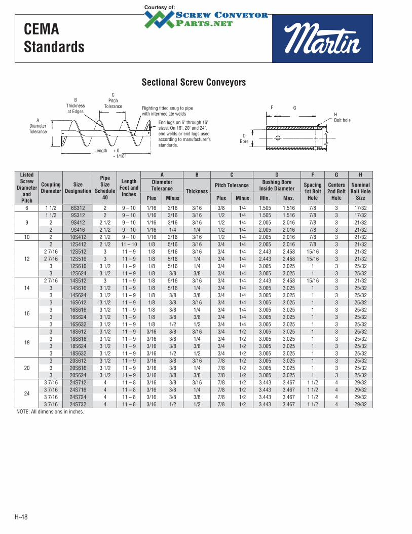
H-48
Listed
Screw
Diameter
and
Pitch
Coupling
Diameter
Size
Designation
Pipe
Size
Schedule
40
Length
Feet and
Inches
A B C D F G H
Diameter
ToleranceThickness
Pitch ToleranceBushing Bore
Inside DiameterSpacing
1st Bolt
Hole
Centers
2nd Bolt
Hole
Nominal
Bolt Hole
SizePlus Minus Plus Minus Min. Max.
6 1 1/2 6S312 2 9 – 10 1/16 3/16 3/16 3/8 1/4 1.505 1.516 7/8 3 17/32
91 1/2 9S312 2 9 – 10 1/16 3/16 3/16 1/2 1/4 1.505 1.516 7/8 3 17/32
2 9S412 2 1/2 9 – 10 1/16 3/16 3/16 1/2 1/4 2.005 2.016 7/8 3 21/322 9S416 2 1/2 9 – 10 1/16 1/4 1/4 1/2 1/4 2.005 2.016 7/8 3 21/32
10 2 10S412 2 1/2 9 – 10 1/16 3/16 3/16 1/2 1/4 2.005 2.016 7/8 3 21/32
12
2 12S412 2 1/2 11 – 10 1/8 5/16 3/16 3/4 1/4 2.005 2.016 7/8 3 21/322 7/16 12S512 3 11 – 9 1/8 5/16 3/16 3/4 1/4 2.443 2.458 15/16 3 21/322 7/16 12S516 3 11 – 9 1/8 5/16 1/4 3/4 1/4 2.443 2.458 15/16 3 21/32
3 12S616 3 1/2 11 – 9 1/8 5/16 1/4 3/4 1/4 3.005 3.025 1 3 25/323 12S624 3 1/2 11 – 9 1/8 3/8 3/8 3/4 1/4 3.005 3.025 1 3 25/32
142 7/16 14S512 3 11 – 9 1/8 5/16 3/16 3/4 1/4 2.443 2.458 15/16 3 21/32
3 14S616 3 1/2 11 – 9 1/8 5/16 1/4 3/4 1/4 3.005 3.025 1 3 25/323 14S624 3 1/2 11 – 9 1/8 3/8 3/8 3/4 1/4 3.005 3.025 1 3 25/32
16
3 16S612 3 1/2 11 – 9 1/8 3/8 3/16 3/4 1/4 3.005 3.025 1 3 25/323 16S616 3 1/2 11 – 9 1/8 3/8 1/4 3/4 1/4 3.005 3.025 1 3 25/323 16S624 3 1/2 11 – 9 1/8 3/8 3/8 3/4 1/4 3.005 3.025 1 3 25/323 16S632 3 1/2 11 – 9 1/8 1/2 1/2 3/4 1/4 3.005 3.025 1 3 25/32
18
3 18S612 3 1/2 11 – 9 3/16 3/8 3/16 3/4 1/2 3.005 3.025 1 3 25/323 18S616 3 1/2 11 – 9 3/16 3/8 1/4 3/4 1/2 3.005 3.025 1 3 25/323 18S624 3 1/2 11 – 9 3/16 3/8 3/8 3/4 1/2 3.005 3.025 1 3 25/323 18S632 3 1/2 11 – 9 3/16 1/2 1/2 3/4 1/2 3.005 3.025 1 3 25/32
203 20S612 3 1/2 11 – 9 3/16 3/8 3/16 7/8 1/2 3.005 3.025 1 3 25/323 20S616 3 1/2 11 – 9 3/16 3/8 1/4 7/8 1/2 3.005 3.025 1 3 25/323 20S624 3 1/2 11 – 9 3/16 3/8 3/8 7/8 1/2 3.005 3.025 1 3 25/32
24
3 7/16 24S712 4 11 – 8 3/16 3/8 3/16 7/8 1/2 3.443 3.467 1 1/2 4 29/323 7/16 24S716 4 11 – 8 3/16 3/8 1/4 7/8 1/2 3.443 3.467 1 1/2 4 29/323 7/16 24S724 4 11 – 8 3/16 3/8 3/8 7/8 1/2 3.443 3.467 1 1/2 4 29/323 7/16 24S732 4 11 – 8 3/16 1/2 1/2 7/8 1/2 3.443 3.467 1 1/2 4 29/32
NOTE: All dimensions in inches.
Sectional Screw Conveyors
BThickness at Edges
DBore
HBolt hole
CPitch
Tolerance Flighting fitted snug to pipe with intermediate welds
End lugs on 6" through 16" sizes. On 18", 20" and 24", end welds or end lugs used according to manufacturer’s standards.
Length + 0 - 1/16"
CEMA
Standards
ADiameterTolerance
F G
H-49
Components
COMPONENTS PAGE
COMPONENT SELECTION . . . . . . . . . . . . . . . . . . . . . . . . . . . . . . . . . . . . . . . . . . . . . . . . . . . . . . . . . . . . . . . . . . . . . . . H-50
TROUGH . . . . . . . . . . . . . . . . . . . . . . . . . . . . . . . . . . . . . . . . . . . . . . . . . . . . . . . . . . . . . . . . . . . . . . . . . . . . . . . . . . . . H-52
DISCHARGES AND GATES . . . . . . . . . . . . . . . . . . . . . . . . . . . . . . . . . . . . . . . . . . . . . . . . . . . . . . . . . . . . . . . . . . . . . . H-56
TROUGH ENDS . . . . . . . . . . . . . . . . . . . . . . . . . . . . . . . . . . . . . . . . . . . . . . . . . . . . . . . . . . . . . . . . . . . . . . . . . . . . . . . H-62
SADDLES AND FEET/TROUGH END FLANGES . . . . . . . . . . . . . . . . . . . . . . . . . . . . . . . . . . . . . . . . . . . . . . . . . . . . . . . H-69
END BEARINGS . . . . . . . . . . . . . . . . . . . . . . . . . . . . . . . . . . . . . . . . . . . . . . . . . . . . . . . . . . . . . . . . . . . . . . . . . . . . . . . H-70
THRUST BEARINGS . . . . . . . . . . . . . . . . . . . . . . . . . . . . . . . . . . . . . . . . . . . . . . . . . . . . . . . . . . . . . . . . . . . . . . . . . . . H-72
SEALS . . . . . . . . . . . . . . . . . . . . . . . . . . . . . . . . . . . . . . . . . . . . . . . . . . . . . . . . . . . . . . . . . . . . . . . . . . . . . . . . . . . . . H-74
CONVEYOR SCREWS . . . . . . . . . . . . . . . . . . . . . . . . . . . . . . . . . . . . . . . . . . . . . . . . . . . . . . . . . . . . . . . . . . . . . . . . . . . H-77
COUPLING BOLTS, INTERNAL COLLARS AND LUGS . . . . . . . . . . . . . . . . . . . . . . . . . . . . . . . . . . . . . . . . . . . . . . . . . . H-85
SHAFTS . . . . . . . . . . . . . . . . . . . . . . . . . . . . . . . . . . . . . . . . . . . . . . . . . . . . . . . . . . . . . . . . . . . . . . . . . . . . . . . . . . . . . H-86
HANGERS . . . . . . . . . . . . . . . . . . . . . . . . . . . . . . . . . . . . . . . . . . . . . . . . . . . . . . . . . . . . . . . . . . . . . . . . . . . . . . . . . . . H-91
HANGER BEARINGS . . . . . . . . . . . . . . . . . . . . . . . . . . . . . . . . . . . . . . . . . . . . . . . . . . . . . . . . . . . . . . . . . . . . . . . . . . . H-99
COVERS . . . . . . . . . . . . . . . . . . . . . . . . . . . . . . . . . . . . . . . . . . . . . . . . . . . . . . . . . . . . . . . . . . . . . . . . . . . . . . . . . . . H-101
COVER ACCESSORIES . . . . . . . . . . . . . . . . . . . . . . . . . . . . . . . . . . . . . . . . . . . . . . . . . . . . . . . . . . . . . . . . . . . . . . . . . H-104
CONVEYOR SHROUDS . . . . . . . . . . . . . . . . . . . . . . . . . . . . . . . . . . . . . . . . . . . . . . . . . . . . . . . . . . . . . . . . . . . . . . . . H-106

H-50
Required Information
Screw diameter
Shaft diameter
Material component group
Unusual material characteristics
Conveyor Screws
Standard length conveyor screws should be used whenever possible to reduce the number of hanger bearings required.
The recommended screws listed in the Component Series Table are standard helicoid and sectional screw conveyors. The use of helicoid or sectional conveyors is largely a matter of individual preference.
Right hand screw conveyors pull material toward the end which is being rotated in a clockwise direction. If the rotation is reversed (counterclockwise), the material is pushed away from that end.
In left hand screw conveyors, the material flow is opposite to that of right hand screws, the direction of rotation being unchanged.
To determine hand of screw see pages H-37 and H-38.
The material is carried on one face of the conveyor flighting in conveyors which are required to transport material in one direction, therefore, conveyor end lugs are located on the opposite face to facilitate unimpeded flow of the material. Conveyor sections must be installed in such a manner that all end lugs are toward the inlet end of the conveyor. Conveyor sections must not be turned end for end without reversing the direction of rotation, or conversely, the direction of rotation must not be reversed without turning the conveyor sections end for end.
Requirements for reversible conveyor screws intended for material transport in either direction should be referred to our Engineering Department.
Flighting should be omitted from the conveyor pipe over the last discharge opening to ensure complete discharge of material without carryover.
Continuity of material flow at hanger points is accomplished by opposing adjacent flight ends approximately 180º. (As close to 180° as the predrilled holes will allow.)
Conveyor Trough and Tubular Housing
Standard trough and housing sections are available in five, six, ten, and 12 foot lengths. Standard five and six foot lengths should be used when connecting flanges coincide with discharge openings or hanger bearings.
Shafts
The primary consideration in determining the type and size of coupling and drive shafts is whether the shafts selected are adequate to transmit the horsepower required, including any overload. Normally, cold-rolled shafts are adequate. However, high-tensile shafts may be required due to torque limitations. Also, stainless steel shafts may be necessary when corrosive or contaminable materials are to be handled. Conveyors equipped with non-lubricated hard iron hanger bearings require hardened coupling shafts. Specific shaft size determination is covered in the Torsional Rating Section, page H-26.
Shaft Seals
Several conveyor end seal types are available to prevent contamination of the conveyed material or to prevent the escape of material from the system.
Bearings
Hanger Bearing. The purpose of hanger bearings is to provide intermediate support when multiple screw sections are used. Hanger bearings are designed primarily for radial loads. Therefore, adequate clearance should be allowed between the bearings and the conveyor pipe ends to prevent damage by the thrust load which is transmitted through the conveyor pipe.
The hanger bearing recommendations listed in the Material Characteristic Tables are generally adequate for the material to be handled. Often, however, unusual characteristics of the material or the conditions under which the conveyor must operate make it desirable to use special bearing materials. Regarding the use of special bearing materials, consult our Engineering Department.
End Bearings. Several end bearing types are available, and their selection depends on two basic factors: Radial load and thrust load. The relative values of these loads determines end bearing types.
Radial load is negligible at the conveyor tail shaft. However, drive ends (unless integrated with the conveyor end plate) are subject to radial loading due to overhung drive loads, such as chain sprockets or shaft-mounted speed reducers. Screw Conveyor Drive Reducers at the drive end will adequately carry both thrust and radial loads.
Component
Selection
H-51
Discharge Spouts and Gates
Standard discharge spouts and gates are available for either conveyor trough or tubular housing in several designs, operated either manually or by remote controls.
In installations where it is possible to overfill the device to which material is being transported, an additional overflow discharge opening or overflow relief device should be provided. Consult our Engineering Department for suggested electrical interlock and safety devices to prevent overflow or damage to equipment.
It is sometimes found that the material characteristics are such that standard component specifications are inadequate. Should unusual material characteristics or severe conditions exist, our Engineering Department should be consulted.
Conveyor Ends
A complete line of conveyor ends are available as standard for either conveyor trough or tubular housing with a choice of many bearing types and combinations.
Special Applications
More common of the unusual material characteristics which require other than the recommended components are:
Corrosive Materials. Components may be fabricated from alloys not affected by the material or may be coated with a protective substance.
Contaminable Materials. Require the use of oil impregnated, sealed, or dry type hanger bearings. End shafts should be sealed to prevent entrance of contaminants from the outside. Due to the necessity for frequent cleaning conveyor components should be designed for convenient disassembly.
Abrasive Materials. These materials may be handled in conveyors, troughs, or housings constructed of abrasion resistant alloys with hard surfaced screws. Lining of all exposed surfaces with rubber or special resins also materially reduces abrasive damage.
Interlocking or Matting Materials. Conveying with standard components is sometimes possible by the use of special feeding devices at the conveyor inlet.
Hygroscopic Materials. Frequently these materials may be handled successfully in a conveyor which is substantially sealed from the exterior atmosphere. In extreme cases it is necessary to provide jacketed trough or housing with an appropriate circulating medium to maintain the material at an elevated temperature. Purging of the conveyor with a suitable dry gas is also used in some installations.
Viscous or Sticky Materials. Ribbon flight conveyor screws are most frequently used for conveying these materials although standard components may be specially coated to improve the flow of material.
Harmful Vapors or Dusts. These materials may be safely handled in dust sealed trough, plain tubular housing, or gasketed flanged tubular housing with particular attention to shaft sealing. Trough or housing exhaust systems have also been successfully used in some installations.
Blending in Transit. Ribbon, cut flight, paddle, or a combination of these screw types may be designed to produce the desired degree of blending, aeration or mixing.
Explosive Dusts. The danger of this condition may be minimized in most installations by the use of components which are fabricated from non-ferrous materials and proper conveyor sealing techniques observed. Exhaust systems are also advisable for the removal of explosive dusts.
Materials Subject to Packing. This condition requires the use of aerating devices at the conveyor inlet when materials are pulverulent and a special feeder device when material particles are large or fibrous.
Materials which are Fluid when Aerated. This condition may be used to advantage in some installations by declining the conveyor system toward the discharge end.
Degradable Materials. Some particles that are easily broken or distorted may usually be handled in screw conveyors by reducing the speed and selecting a larger conveyor size sufficient to deliver the required volume of material.
Elevated Temperature. Components should be fabricated from high temperature alloys. Should the process be such that cooling of the material in the conveyor is permissible, jacketed trough or housing may be used at the inlet end to cool the material and standard components used after the point where material temperature has been reduced to a safe degree.
Component
Selection
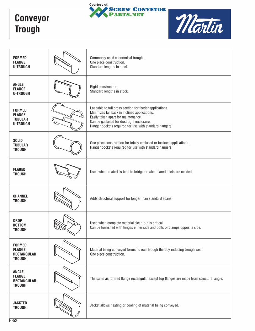
H-52
Conveyor
Trough
FORMED
FLANGE
U-TROUGH
Commonly used economical trough.One piece construction.Standard lengths in stock
ANGLE
FLANGE
U-TROUGH
Rigid construction.Standard lengths in stock.
FORMED
FLANGE
TUBULAR
U-TROUGH
Loadable to full cross section for feeder applications.Minimizes fall back in inclined applications.Easily taken apart for maintenance.Can be gasketed for dust tight enclosure.Hanger pockets required for use with standard hangers.
SOLID
TUBULAR
TROUGH
One piece construction for totally enclosed or inclined applications.Hanger pockets required for use with standard hangers.
FLARED
TROUGHUsed where materials tend to bridge or when flared inlets are needed.
CHANNEL
TROUGHAdds structural support for longer than standard spans.
DROP
BOTTOM
TROUGH
Used when complete material clean-out is critical.Can be furnished with hinges either side and bolts or clamps opposite side.
FORMED
FLANGE
RECTANGULAR
TROUGH
Material being conveyed forms its own trough thereby reducing trough wear.One piece construction.
ANGLE
FLANGE
RECTANGULAR
TROUGH
The same as formed flange rectangular except top flanges are made from structural angle.
JACKTED
TROUGHJacket allows heating or cooling of material being conveyed.
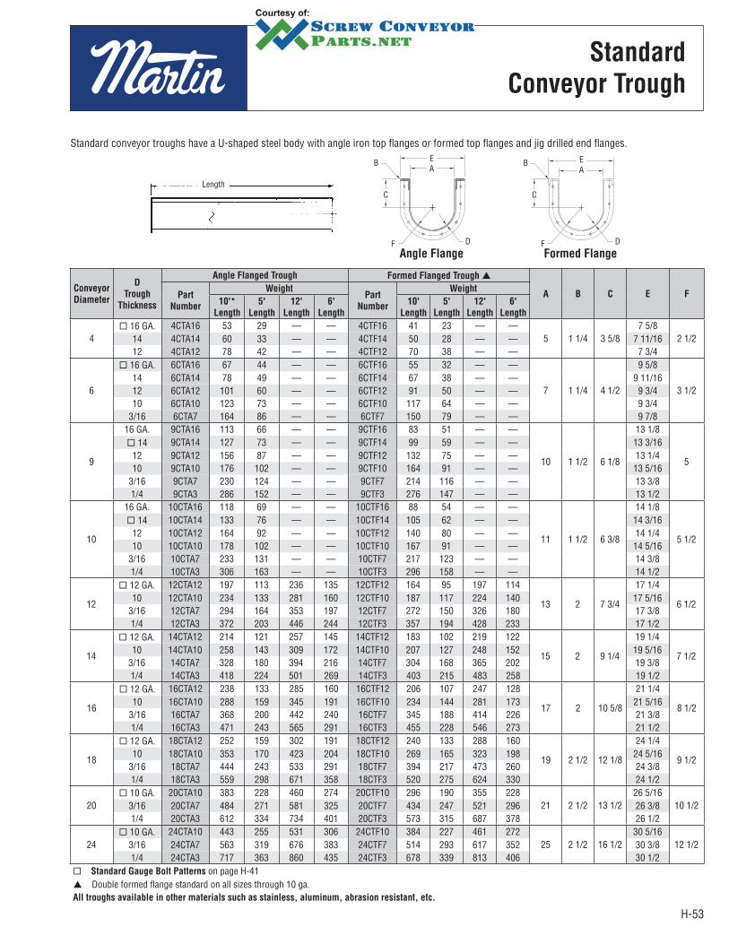
H-53
Conveyor
Diameter
D
Trough
Thickness
Angle Flanged Trough Formed Flanged Trough
A B C E FPart
Number
WeightPart
Number
Weight
10'*
Length
5'
Length
12'
Length
6'
Length
10'
Length
5'
Length
12'
Length
6'
Length
4 16 GA. 4CTA16 53 29 — — 4CTF16 41 23 — —
5 1 1/4 3 5/87 5/8
2 1/214 4CTA14 60 33 — — 4CTF14 50 28 — — 7 11/1612 4CTA12 78 42 — — 4CTF12 70 38 — — 7 3/4
6
16 GA. 6CTA16 67 44 — — 6CTF16 55 32 — —
7 1 1/4 4 1/2
9 5/8
3 1/214 6CTA14 78 49 — — 6CTF14 67 38 — — 9 11/1612 6CTA12 101 60 — — 6CTF12 91 50 — — 9 3/410 6CTA10 123 73 — — 6CTF10 117 64 — — 9 3/4
3/16 6CTA7 164 86 — — 6CTF7 150 79 — — 9 7/8
9
16 GA. 9CTA16 113 66 — — 9CTF16 83 51 — —
10 1 1/2 6 1/8
13 1/8
5
14 9CTA14 127 73 — — 9CTF14 99 59 — — 13 3/1612 9CTA12 156 87 — — 9CTF12 132 75 — — 13 1/410 9CTA10 176 102 — — 9CTF10 164 91 — — 13 5/16
3/16 9CTA7 230 124 — — 9CTF7 214 116 — — 13 3/81/4 9CTA3 286 152 — — 9CTF3 276 147 — — 13 1/2
10
16 GA. 10CTA16 118 69 — — 10CTF16 88 54 — —
11 1 1/2 6 3/8
14 1/8
5 1/2
14 10CTA14 133 76 — — 10CTF14 105 62 — — 14 3/1612 10CTA12 164 92 — — 10CTF12 140 80 — — 14 1/410 10CTA10 178 102 — — 10CTF10 167 91 — — 14 5/16
3/16 10CTA7 233 131 — — 10CTF7 217 123 — — 14 3/81/4 10CTA3 306 163 — — 10CTF3 296 158 — — 14 1/2
12
12 GA. 12CTA12 197 113 236 135 12CTF12 164 95 197 114
13 2 7 3/4
17 1/4
6 1/210 12CTA10 234 133 281 160 12CTF10 187 117 224 140 17 5/16
3/16 12CTA7 294 164 353 197 12CTF7 272 150 326 180 17 3/81/4 12CTA3 372 203 446 244 12CTF3 357 194 428 233 17 1/2
14
12 GA. 14CTA12 214 121 257 145 14CTF12 183 102 219 122
15 2 9 1/4
19 1/4
7 1/210 14CTA10 258 143 309 172 14CTF10 207 127 248 152 19 5/16
3/16 14CTA7 328 180 394 216 14CTF7 304 168 365 202 19 3/81/4 14CTA3 418 224 501 269 14CTF3 403 215 483 258 19 1/2
16
12 GA. 16CTA12 238 133 285 160 16CTF12 206 107 247 128
17 2 10 5/8
21 1/4
8 1/210 16CTA10 288 159 345 191 16CTF10 234 144 281 173 21 5/16
3/16 16CTA7 368 200 442 240 16CTF7 345 188 414 226 21 3/81/4 16CTA3 471 243 565 291 16CTF3 455 228 546 273 21 1/2
18
12 GA. 18CTA12 252 159 302 191 18CTF12 240 133 288 160
19 2 1/2 12 1/8
24 1/4
9 1/210 18CTA10 353 170 423 204 18CTF10 269 165 323 198 24 5/16
3/16 18CTA7 444 243 533 291 18CTF7 394 217 473 260 24 3/81/4 18CTA3 559 298 671 358 18CTF3 520 275 624 330 24 1/2
20 10 GA. 20CTA10 383 228 460 274 20CTF10 296 190 355 228
21 2 1/2 13 1/226 5/16
10 1/23/16 20CTA7 484 271 581 325 20CTF7 434 247 521 296 26 3/81/4 20CTA3 612 334 734 401 20CTF3 573 315 687 378 26 1/2
24 10 GA. 24CTA10 443 255 531 306 24CTF10 384 227 461 272
25 2 1/2 16 1/230 5/16
12 1/23/16 24CTA7 563 319 676 383 24CTF7 514 293 617 352 30 3/81/4 24CTA3 717 363 860 435 24CTF3 678 339 813 406 30 1/2
Standard Gauge Bolt Patterns on page H-41Double formed flange standard on all sizes through 10 ga.
All troughs available in other materials such as stainless, aluminum, abrasion resistant, etc.
Standard
Conveyor Trough
Standard conveyor troughs have a U-shaped steel body with angle iron top flanges or formed top flanges and jig drilled end flanges.
Length
Angle FlangeF D
C
BAE
Formed FlangeF D
C
BAE
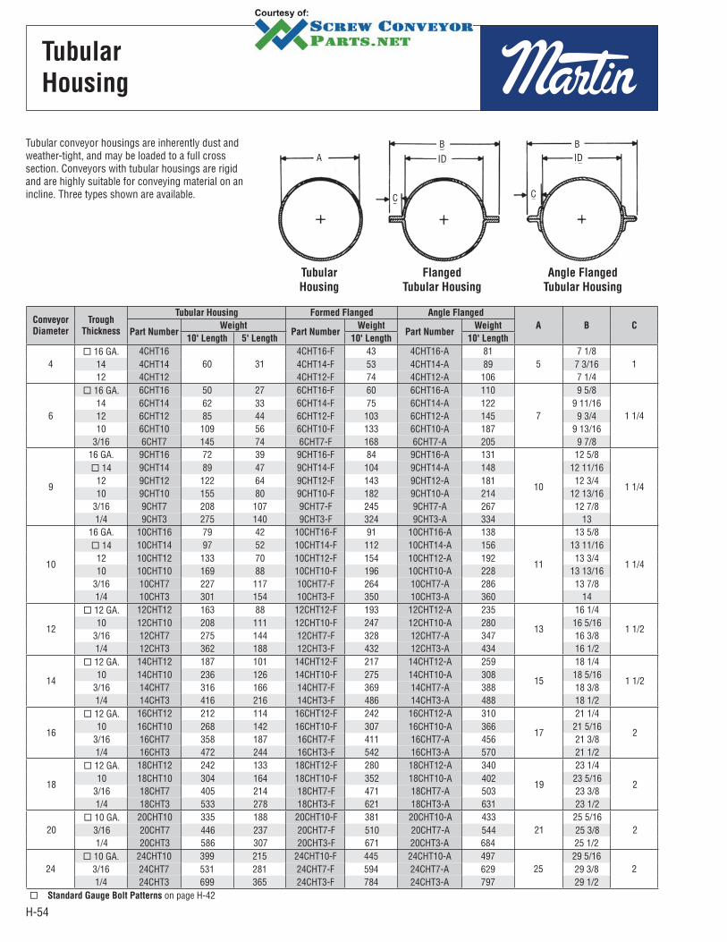
H-54
Tubular
Housing
Tubular conveyor housings are inherently dust and weather-tight, and may be loaded to a full cross section. Conveyors with tubular housings are rigid and are highly suitable for conveying material on an incline. Three types shown are available.
Tubular
Housing
Flanged
Tubular Housing
Angle Flanged
Tubular Housing
AB
C C
BIDID
Conveyor
Diameter
Trough
Thickness
Tubular Housing Formed Flanged Angle Flanged
A B CPart Number
WeightPart Number
WeightPart Number
Weight
10' Length 5' Length 10' Length 10' Length
4 16 GA. 4CHT16
60 314CHT16-F 43 4CHT16-A 81
57 1/8
114 4CHT14 4CHT14-F 53 4CHT14-A 89 7 3/1612 4CHT12 4CHT12-F 74 4CHT12-A 106 7 1/4
6
16 GA. 6CHT16 50 27 6CHT16-F 60 6CHT16-A 110
7
9 5/8
1 1/414 6CHT14 62 33 6CHT14-F 75 6CHT14-A 122 9 11/1612 6CHT12 85 44 6CHT12-F 103 6CHT12-A 145 9 3/410 6CHT10 109 56 6CHT10-F 133 6CHT10-A 187 9 13/16
3/16 6CHT7 145 74 6CHT7-F 168 6CHT7-A 205 9 7/8
9
16 GA. 9CHT16 72 39 9CHT16-F 84 9CHT16-A 131
10
12 5/8
1 1/4
14 9CHT14 89 47 9CHT14-F 104 9CHT14-A 148 12 11/1612 9CHT12 122 64 9CHT12-F 143 9CHT12-A 181 12 3/410 9CHT10 155 80 9CHT10-F 182 9CHT10-A 214 12 13/16
3/16 9CHT7 208 107 9CHT7-F 245 9CHT7-A 267 12 7/81/4 9CHT3 275 140 9CHT3-F 324 9CHT3-A 334 13
10
16 GA. 10CHT16 79 42 10CHT16-F 91 10CHT16-A 138
11
13 5/8
1 1/4
14 10CHT14 97 52 10CHT14-F 112 10CHT14-A 156 13 11/1612 10CHT12 133 70 10CHT12-F 154 10CHT12-A 192 13 3/410 10CHT10 169 88 10CHT10-F 196 10CHT10-A 228 13 13/16
3/16 10CHT7 227 117 10CHT7-F 264 10CHT7-A 286 13 7/81/4 10CHT3 301 154 10CHT3-F 350 10CHT3-A 360 14
12
12 GA. 12CHT12 163 88 12CHT12-F 193 12CHT12-A 235
13
16 1/4
1 1/210 12CHT10 208 111 12CHT10-F 247 12CHT10-A 280 16 5/16
3/16 12CHT7 275 144 12CHT7-F 328 12CHT7-A 347 16 3/81/4 12CHT3 362 188 12CHT3-F 432 12CHT3-A 434 16 1/2
14
12 GA. 14CHT12 187 101 14CHT12-F 217 14CHT12-A 259
15
18 1/4
1 1/210 14CHT10 236 126 14CHT10-F 275 14CHT10-A 308 18 5/16
3/16 14CHT7 316 166 14CHT7-F 369 14CHT7-A 388 18 3/81/4 14CHT3 416 216 14CHT3-F 486 14CHT3-A 488 18 1/2
16
12 GA. 16CHT12 212 114 16CHT12-F 242 16CHT12-A 310
17
21 1/4
210 16CHT10 268 142 16CHT10-F 307 16CHT10-A 366 21 5/16
3/16 16CHT7 358 187 16CHT7-F 411 16CHT7-A 456 21 3/81/4 16CHT3 472 244 16CHT3-F 542 16CHT3-A 570 21 1/2
18
12 GA. 18CHT12 242 133 18CHT12-F 280 18CHT12-A 340
19
23 1/4
210 18CHT10 304 164 18CHT10-F 352 18CHT10-A 402 23 5/16
3/16 18CHT7 405 214 18CHT7-F 471 18CHT7-A 503 23 3/81/4 18CHT3 533 278 18CHT3-F 621 18CHT3-A 631 23 1/2
20 10 GA. 20CHT10 335 188 20CHT10-F 381 20CHT10-A 433
2125 5/16
23/16 20CHT7 446 237 20CHT7-F 510 20CHT7-A 544 25 3/81/4 20CHT3 586 307 20CHT3-F 671 20CHT3-A 684 25 1/2
24 10 GA. 24CHT10 399 215 24CHT10-F 445 24CHT10-A 497
2529 5/16
23/16 24CHT7 531 281 24CHT7-F 594 24CHT7-A 629 29 3/81/4 24CHT3 699 365 24CHT3-F 784 24CHT3-A 797 29 1/2
Standard Gauge Bolt Patterns on page H-42
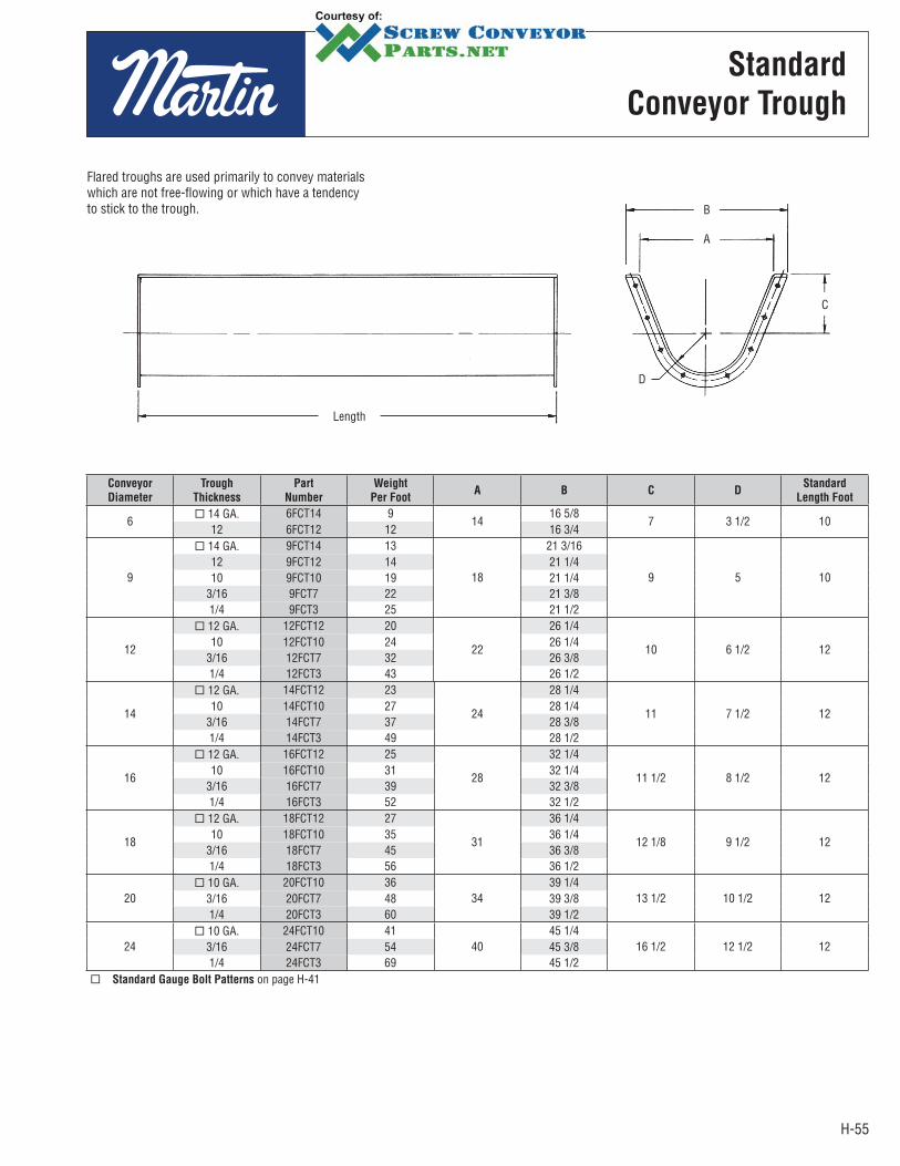
H-55
Flared troughs are used primarily to convey materials which are not free-flowing or which have a tendency to stick to the trough.
Conveyor
Diameter
Trough
Thickness
Part
Number
Weight
Per FootA B C D
Standard
Length Foot
6 14 GA. 6FCT14 9
1416 5/8
7 3 1/2 1012 6FCT12 12 16 3/4
9
14 GA. 9FCT14 13
18
21 3/16
9 5 1012 9FCT12 14 21 1/410 9FCT10 19 21 1/4
3/16 9FCT7 22 21 3/81/4 9FCT3 25 21 1/2
12
12 GA. 12FCT12 20
22
26 1/4
10 6 1/2 1210 12FCT10 24 26 1/4
3/16 12FCT7 32 26 3/81/4 12FCT3 43 26 1/2
14
12 GA. 14FCT12 23
24
28 1/4
11 7 1/2 1210 14FCT10 27 28 1/4
3/16 14FCT7 37 28 3/81/4 14FCT3 49 28 1/2
16
12 GA. 16FCT12 25
28
32 1/4
11 1/2 8 1/2 1210 16FCT10 31 32 1/4
3/16 16FCT7 39 32 3/81/4 16FCT3 52 32 1/2
18
12 GA. 18FCT12 27
31
36 1/4
12 1/8 9 1/2 1210 18FCT10 35 36 1/4
3/16 18FCT7 45 36 3/81/4 18FCT3 56 36 1/2
20 10 GA. 20FCT10 36
3439 1/4
13 1/2 10 1/2 123/16 20FCT7 48 39 3/81/4 20FCT3 60 39 1/2
24 10 GA. 24FCT10 41
4045 1/4
16 1/2 12 1/2 123/16 24FCT7 54 45 3/81/4 24FCT3 69 45 1/2
Standard Gauge Bolt Patterns on page H-41
Standard
Conveyor Trough
Length
D
C
A
B
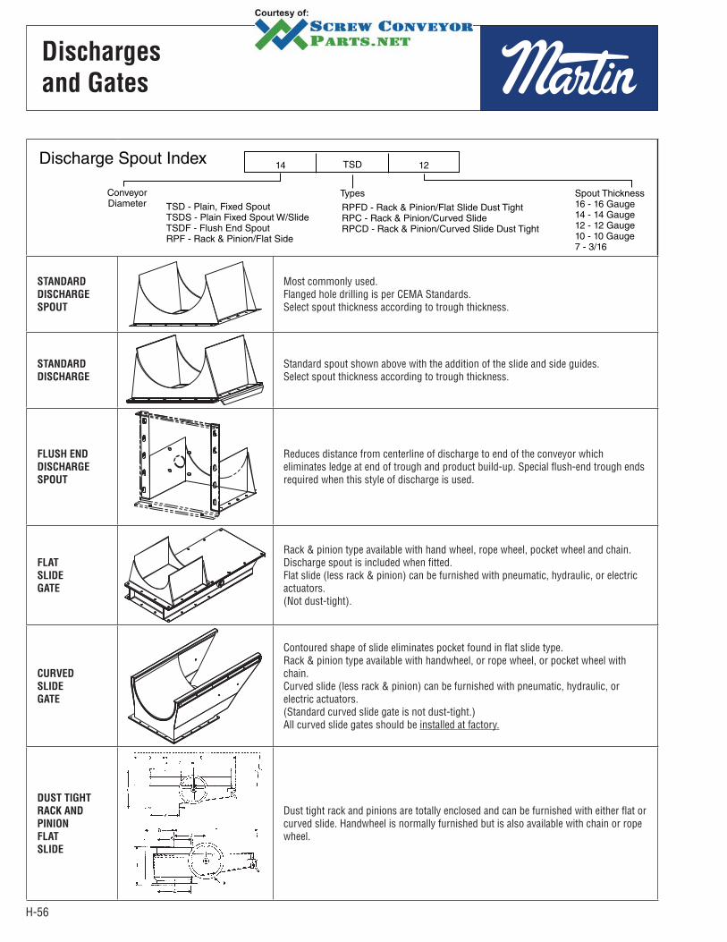
H-56
Discharges
and Gates
STANDARD
DISCHARGE
SPOUT
Most commonly used.Flanged hole drilling is per CEMA Standards.Select spout thickness according to trough thickness.
STANDARD
DISCHARGE
Standard spout shown above with the addition of the slide and side guides.Select spout thickness according to trough thickness.
FLUSH END
DISCHARGE
SPOUT
Reduces distance from centerline of discharge to end of the conveyor which eliminates ledge at end of trough and product build-up. Special flush-end trough ends required when this style of discharge is used.
FLAT
SLIDE
GATE
Rack & pinion type available with hand wheel, rope wheel, pocket wheel and chain. Discharge spout is included when fitted.Flat slide (less rack & pinion) can be furnished with pneumatic, hydraulic, or electric actuators.(Not dust-tight).
CURVED
SLIDE
GATE
Contoured shape of slide eliminates pocket found in flat slide type.Rack & pinion type available with handwheel, or rope wheel, or pocket wheel with chain.Curved slide (less rack & pinion) can be furnished with pneumatic, hydraulic, or electric actuators.(Standard curved slide gate is not dust-tight.)All curved slide gates should be installed at factory.
DUST TIGHT
RACK AND
PINION
FLAT
SLIDE
Dust tight rack and pinions are totally enclosed and can be furnished with either flat or curved slide. Handwheel is normally furnished but is also available with chain or rope wheel.
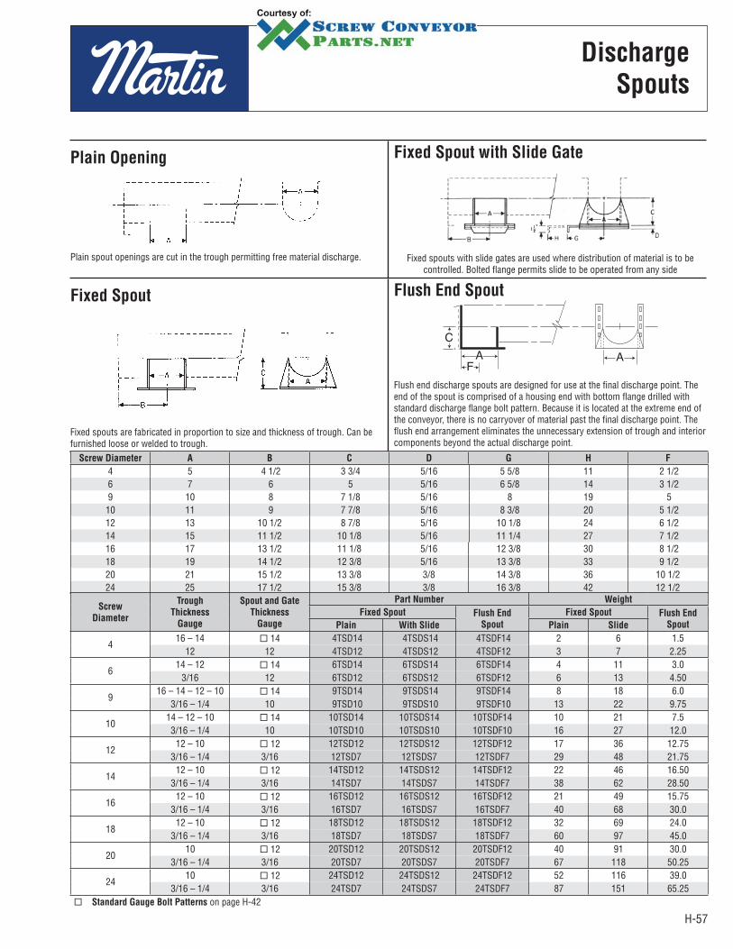
H-57
Plain Opening
Plain spout openings are cut in the trough permitting free material discharge.
Fixed Spout with Slide Gate
Fixed spouts with slide gates are used where distribution of material is to be controlled. Bolted flange permits slide to be operated from any side
Fixed Spout
Fixed spouts are fabricated in proportion to size and thickness of trough. Can be furnished loose or welded to trough.
Flush End Spout
Flush end discharge spouts are designed for use at the final discharge point. The end of the spout is comprised of a housing end with bottom flange drilled with standard discharge flange bolt pattern. Because it is located at the extreme end of the conveyor, there is no carryover of material past the final discharge point. The flush end arrangement eliminates the unnecessary extension of trough and interior components beyond the actual discharge point.
Discharge
Spouts
Screw Diameter A B C D G H F
4 5 4 1/2 3 3/4 5/16 5 5/8 11 2 1/2 6 7 6 5 5/16 6 5/8 14 3 1/2 9 10 8 7 1/8 5/16 8 19 5
10 11 9 7 7/8 5/16 8 3/8 20 5 1/2 12 13 10 1/2 8 7/8 5/16 10 1/8 24 6 1/2 14 15 11 1/2 10 1/8 5/16 11 1/4 27 7 1/2 16 17 13 1/2 11 1/8 5/16 12 3/8 30 8 1/2 18 19 14 1/2 12 3/8 5/16 13 3/8 33 9 1/2 20 21 15 1/2 13 3/8 3/8 14 3/8 36 10 1/2 24 25 17 1/2 15 3/8 3/8 16 3/8 42 12 1/2
Screw
Diameter
Trough
Thickness
Gauge
Spout and Gate
Thickness
Gauge
Part Number Weight
Fixed Spout Flush End
Spout
Fixed Spout Flush End
SpoutPlain With Slide Plain Slide
4 16 – 14 14 4TSD14 4TSDS14 4TSDF14 2 6 1.5
12 12 4TSD12 4TSDS12 4TSDF12 3 7 2.25
6 14 – 12 14 6TSD14 6TSDS14 6TSDF14 4 11 3.0
3/16 12 6TSD12 6TSDS12 6TSDF12 6 13 4.50
9 16 – 14 – 12 – 10 14 9TSD14 9TSDS14 9TSDF14 8 18 6.0
3/16 – 1/4 10 9TSD10 9TSDS10 9TSDF10 13 22 9.75
1014 – 12 – 10 14 10TSD14 10TSDS14 10TSDF14 10 21 7.5 3/16 – 1/4 10 10TSD10 10TSDS10 10TSDF10 16 27 12.0
12 12 – 10 12 12TSD12 12TSDS12 12TSDF12 17 36 12.75
3/16 – 1/4 3/16 12TSD7 12TSDS7 12TSDF7 29 48 21.75
14 12 – 10 12 14TSD12 14TSDS12 14TSDF12 22 46 16.50
3/16 – 1/4 3/16 14TSD7 14TSDS7 14TSDF7 38 62 28.50
16 12 – 10 12 16TSD12 16TSDS12 16TSDF12 21 49 15.75
3/16 – 1/4 3/16 16TSD7 16TSDS7 16TSDF7 40 68 30.0
18 12 – 10 12 18TSD12 18TSDS12 18TSDF12 32 69 24.0
3/16 – 1/4 3/16 18TSD7 18TSDS7 18TSDF7 60 97 45.0
20 10 12 20TSD12 20TSDS12 20TSDF12 40 91 30.0
3/16 – 1/4 3/16 20TSD7 20TSDS7 20TSDF7 67 118 50.25
2410 12 24TSD12 24TSDS12 24TSDF12 52 116 39.0
3/16 – 1/4 3/16 24TSD7 24TSDS7 24TSDF7 87 151 65.25 Standard Gauge Bolt Patterns on page H-42
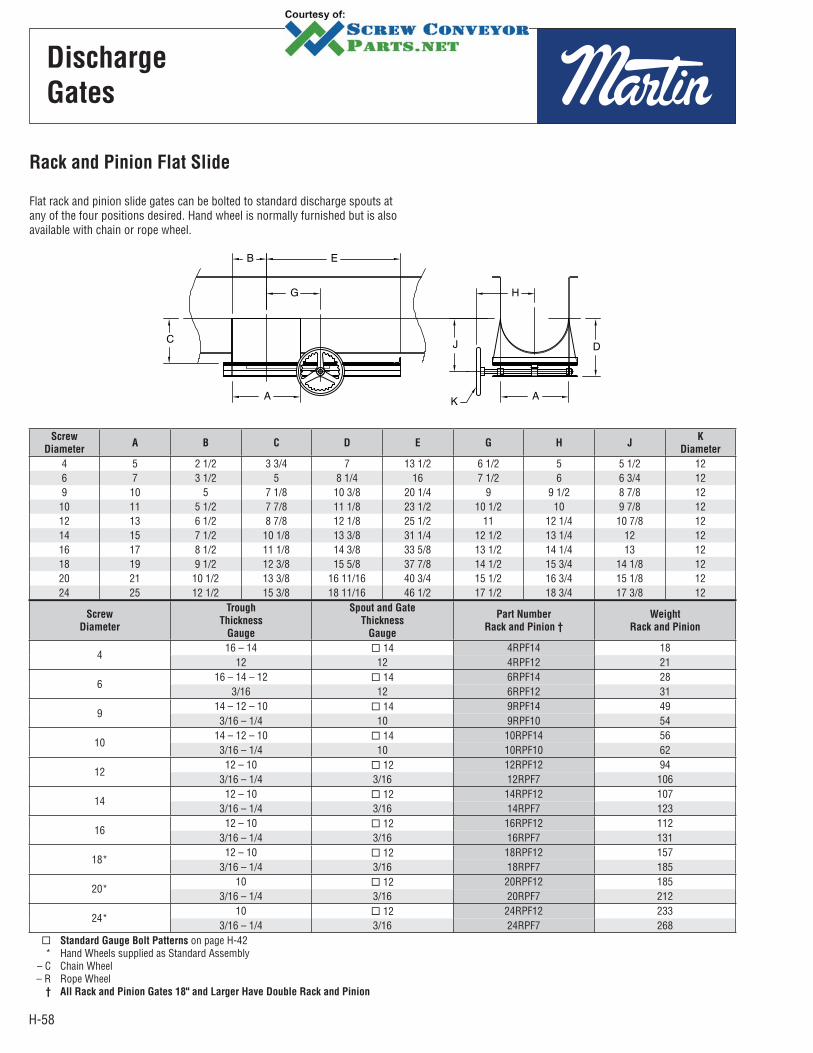
H-58
Screw
DiameterA B C D E G H J
K
Diameter
4 5 2 1/2 3 3/4 7 13 1/2 6 1/2 5 5 1/2 12 6 7 3 1/2 5 8 1/4 16 7 1/2 6 6 3/4 12 9 10 5 7 1/8 10 3/8 20 1/4 9 9 1/2 8 7/8 12
10 11 5 1/2 7 7/8 11 1/8 23 1/2 10 1/2 10 9 7/8 12 12 13 6 1/2 8 7/8 12 1/8 25 1/2 11 12 1/4 10 7/8 12 14 15 7 1/2 10 1/8 13 3/8 31 1/4 12 1/2 13 1/4 12 12 16 17 8 1/2 11 1/8 14 3/8 33 5/8 13 1/2 14 1/4 13 12 18 19 9 1/2 12 3/8 15 5/8 37 7/8 14 1/2 15 3/4 14 1/8 12 20 21 10 1/2 13 3/8 16 11/16 40 3/4 15 1/2 16 3/4 15 1/8 12 24 25 1 2 1/2 15 3/8 18 11/16 46 1/2 17 1/2 18 3/4 17 3/8 12
Screw
Diameter
Trough
Thickness
Gauge
Spout and Gate
Thickness
Gauge
Part Number
Rack and Pinion †
Weight
Rack and Pinion
4 16 – 14 14 4RPF14 18
12 12 4RPF12 21
6 16 – 14 – 12 14 6RPF14 28
3/16 12 6RPF12 31
9 14 – 12 – 10 14 9RPF14 493/16 – 1/4 10 9RPF10 54
1014 – 12 – 10 14 10RPF14 563/16 – 1/4 10 10RPF10 62
12 12 – 10 12 12RPF12 94
3/16 – 1/4 3/16 12RPF7 106
14 12 – 10 12 14RPF12 107
3/16 – 1/4 3/16 14RPF7 123
16 12 – 10 12 16RPF12 112
3/16 – 1/4 3/16 16RPF7 131
18*12 – 10 12 18RPF12 157
3/16 – 1/4 3/16 18RPF7 185
20*10 12 20RPF12 185
3/16 – 1/4 3/16 20RPF7 212
24*10 12 24RPF12 233
3/16 – 1/4 3/16 24RPF7 268Standard Gauge Bolt Patterns on page H-42
* Hand Wheels supplied as Standard Assembly – C Chain Wheel – R Rope Wheel † All Rack and Pinion Gates 18" and Larger Have Double Rack and Pinion
Rack and Pinion Flat Slide
Flat rack and pinion slide gates can be bolted to standard discharge spouts at any of the four positions desired. Hand wheel is normally furnished but is also available with chain or rope wheel.
Discharge
Gates
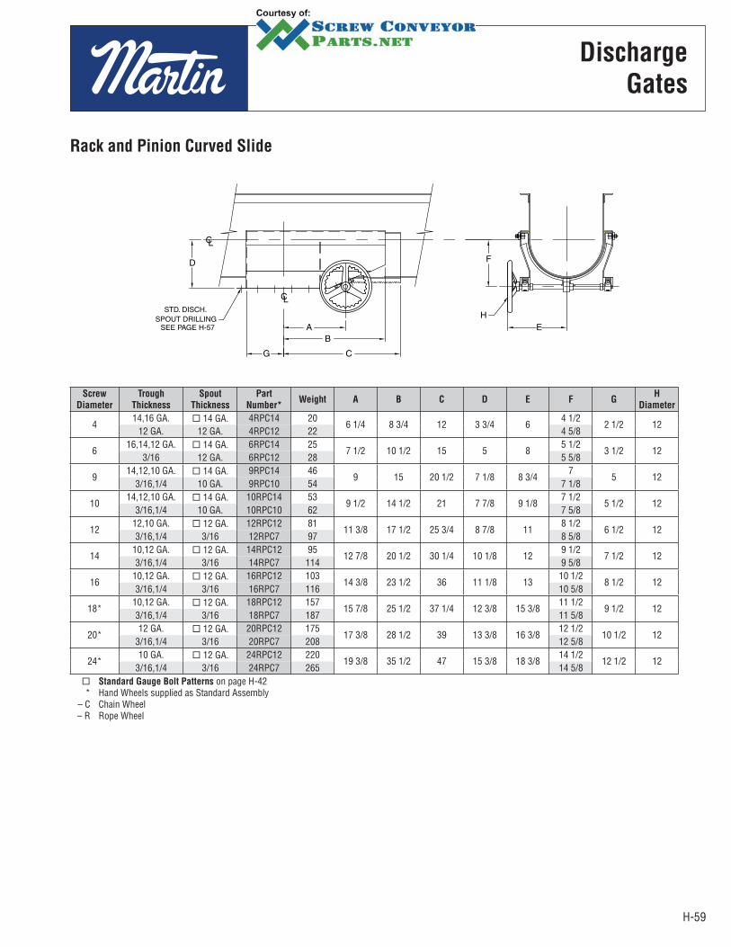
H-59
Screw
Diameter
Trough
Thickness
Spout
Thickness
Part
Number*Weight A B C D E F G
H
Diameter
4 14,16 GA. 14 GA. 4RPC14 20
6 1/4 8 3/4 12 3 3/4 6 4 1/2
2 1/2 1212 GA. 12 GA. 4RPC12 22 4 5/8
6 16,14,12 GA. 14 GA. 6RPC14 25
7 1/2 10 1/2 15 5 8 5 1/2
3 1/2 123/16 12 GA. 6RPC12 28 5 5/8
9 14,12,10 GA. 14 GA. 9RPC14 46
9 15 20 1/2 7 1/8 8 3/4 7
5 123/16,1/4 10 GA. 9RPC10 54 7 1/8
1014,12,10 GA. 14 GA. 10RPC14 53
9 1/2 14 1/2 21 7 7/8 9 1/8 7 1/2
5 1/2 123/16,1/4 10 GA. 10RPC10 62 7 5/8
12 12,10 GA. 12 GA. 12RPC12 81
11 3/8 17 1/2 25 3/4 8 7/8 11 8 1/2
6 1/2 123/16,1/4 3/16 12RPC7 97 8 5/8
14 10,12 GA. 12 GA. 14RPC12 95
12 7/8 20 1/2 30 1/4 10 1/8 12 9 1/2
7 1/2 123/16,1/4 3/16 14RPC7 114 9 5/8
16 10,12 GA. 12 GA. 16RPC12 103
14 3/8 23 1/2 36 11 1/8 13 10 1/2
8 1/2 123/16,1/4 3/16 16RPC7 116 10 5/8
18*10,12 GA. 12 GA. 18RPC12 157
15 7/8 25 1/2 37 1/4 12 3/8 15 3/8 11 1/2
9 1/2 123/16,1/4 3/16 18RPC7 187 11 5/8
20*12 GA. 12 GA. 20RPC12 175
17 3/8 28 1/2 39 13 3/8 16 3/8 12 1/2
10 1/2 123/16,1/4 3/16 20RPC7 208 12 5/8
24*10 GA. 12 GA. 24RPC12 220
19 3/8 35 1/2 47 15 3/8 18 3/8 14 1/2
12 1/2 123/16,1/4 3/16 24RPC7 265 14 5/8
Standard Gauge Bolt Patterns on page H-42 * Hand Wheels supplied as Standard Assembly – C Chain Wheel – R Rope Wheel
Rack and Pinion Curved Slide
Discharge
Gates

H-60
Screw
DiameterA B C D E G H J
K
Diameter
4 5 2 1/2 71/2 2 1/2 12 6 7 7 1/2 126 7 3 1/2 10 4 18 1/2 7 1/2 8 9 129 10 5 12 1/2 5 23 9 11 10 12
10 11 5 1/2 13 5 25 10 11 1/2 10 1/2 1212 13 6 1/2 15 5 28 11 1/2 13 10 1/2 1214 15 7 1/2 15 1/2 5 1/2 31 12 1/2 14 10 1/2 1216 17 8 1/2 16 1/2 5 1/2 34 13 1/2 15 10 1/2 1218 19 9 1/2 18 1/2 6 1/2 38 1/2 15 16 1/2 11 1/2 1220 21 10 1/2 20 7 40 1/2 16 17 1/2 12 1224 25 12 1/2 23 8 47 1/2 18 19 1/2 13 12
Screw
Diameter
Trough
Thickness Gauge
Spout and Gate
Thickness Gauge
Part Number
Flat Slide * Weight Curved Slide * Weight
4 16 – 14 14 4RPFD14 27 4RPCD16 30
12 12 4RPFD12 32 4RPCD12 35
6 16 – 14 – 12 14 66RPFD14 42 6RPCD16 46
3/16 12 6RPFD12 47 6RPCD12 52
9 14 – 12 – 10 14 9RPFD12 74 9RPCD12 813/16 – 1/4 10 9RPFD10 81 9RPCD10 89
1014 – 12 – 10 14 10RPFD14 84 10RPCD14 923/16 – 1/4 10 10RPFD10 93 104PCD10 102
12 12 – 10 12 12RPFD12 141 12RPCD12 155
3/16 – 1/4 3/16 12RPFD7 158 12RPCD7 174
14 12 – 10 12 14RPFD12 160 14RPCD12 176
3/16 – 1/4 3/16 14RPFD7 185 14RPCD7 204
16 12 – 10 12 16RPFD12 168 16RPCD12 185
3/16 – 1/4 3/16 16RPFD7 197 16RPCD7 217
1812 – 10 12 18RPFD12 240 18RPCD12 264
3/16 – 1/4 3/16 18RPFD7 277 18RPCD7 305
2010 12 20RPFD12 278 20RPCD12 306
3/16 – 1/4 3/16 20RPFD7 318 20RPCD7 350
2410 12 24RPFD12 350 24RPCD12 385
3/16 – 1/4 3/16 24RPFD7 402 24RPCD7 442
* Hand Wheels supplied as Standard Assembly – C Chain Wheel – R Rope Wheel
Flange drilling in standard. See page H-43
Discharge
Gates
Dust Tight Rack and Pinion
Flat Slide
Dust tight rack and pinions are totally enclosed and can be furnished with either flat or curved slide. Hand Wheel is normally furnished but is also available with chain or rope wheel.
Dust Tight Rack and Pinion Curved Slide
J
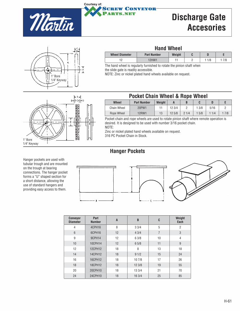
H-61
Conveyor
Diameter
Part
NumberA B C
Weight
Each
4 4CPH16 8 3 3/4 5 2
6 6CPH16 12 4 3/4 7 3
9 9CPH14 12 6 3/8 10 4
10 10CPH14 12 6 5/8 11 9
12 12CPH12 18 8 13 18
14 14CPH12 18 9 1/2 15 24
16 16CPH12 18 10 7/8 17 26
18 18CPH12 18 12 3/8 19 55
20 20CPH10 18 13 3/4 21 70
24 24CPH10 18 16 3/4 25 85
Discharge Gate
Accesories
Hanger Pockets
Hand WheelWheel Diameter Part Number Weight C D E
12 12HW1 11 2 1 1/8 1 7/8
The hand wheel is regularly furnished to rotate the pinion shaft whenthe slide gate is readily accessible.NOTE: Zinc or nickel plated hand wheels available on request.
Pocket Chain Wheel & Rope WheelWheel Part Number Weight A B C D E
Chain Wheel 20PW1 11 12 3/4 2 1 3/8 5/16 2
Rope Wheel 12RW1 13 12 5/8 2 1/4 1 5/8 1 1/4 1 7/8
Pocket chain and rope wheels are used to rotate pinion shaft where remote operation is desired. It is designed to be used with number 3/16 pocket chain.NOTE: Zinc or nickel plated hand wheels available on request.316 PC Pocket Chain in Stock.
1" Bore1/4" Keyway
1" Bore1/4" Keyway
Hanger pockets are used with tubular trough and are mounted on the trough at bearing connections. The hanger pocket forms a “U” shaped section for a short distance, allowing the use of standard hangers and providing easy access to them.
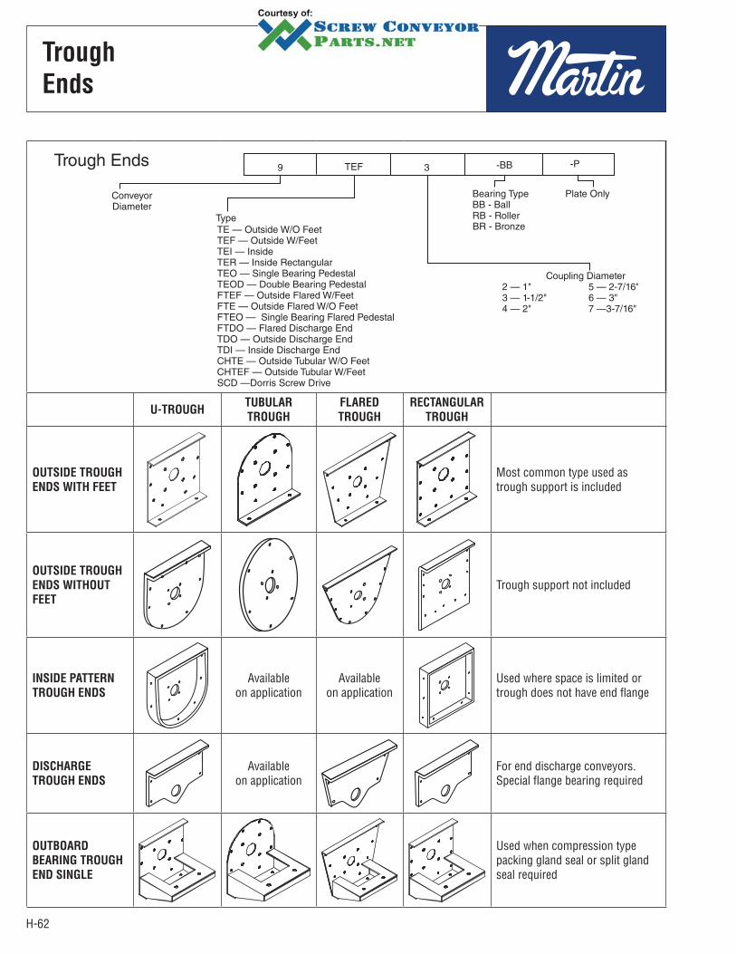
H-62
Trough
Ends
U-TROUGHTUBULAR
TROUGH
FLARED
TROUGH
RECTANGULAR
TROUGH
OUTSIDE TROUGH
ENDS WITH FEET
Most common type used as trough support is included
OUTSIDE TROUGH
ENDS WITHOUT
FEET
Trough support not included
INSIDE PATTERN
TROUGH ENDS
Availableon application
Availableon application
Used where space is limited or trough does not have end flange
DISCHARGE
TROUGH ENDS
Availableon application
For end discharge conveyors. Special flange bearing required
OUTBOARD
BEARING TROUGH
END SINGLE
Used when compression type packing gland seal or split gland seal required

H-63
Trough
Ends
Conveyor
Diameter
Shaft
Diameter
Part
NumberB
D
E K L N Weight P SlotFriction
Bearing
Ball
Bearing
Roller
Bearing
4 1 4TE2–* 3 5/8 2 3/16 1 5/8 1 7/16 1/4 8 1/8 3/8 3 7/16 × 9/166 1 1/2 6TE3–* 4 1/2 3 3/16 2 3/16 3 11/16 1 1/2 1/4 10 1/8 3/8 4 7/16 × 9/16
91 1/2 9TE3–* 6 1/8 3 1/4 2 3/16 3 11/16 1 5/8 1/4 13 3/4 3/8 9
7/16 × 9/162 9TE4–* 6 1/8 4 1/4 2 1/2 3 13/16 1 5/8 1/4 13 3/4 3/8 9
101 1/2 10TE3–* 6 3/8 3 1/4 2 3/16 3 11/16 1 3/4 1/4 14 3/4 3/8 11
7/16 × 9/16 2 10TE4–* 6 3/8 4 1/4 2 1/2 3 13/16 1 3/4 1/4 14 3/4 3/8 11
122 12TE4–* 7 3/4 4 1/4 2 9/16 3 7/8 2 1/4 17 1/4 1/2 20
9/16 × 11/16
2 7/16 12TE5–* 7 3/4 5 1/4 2 15/16 4 7/16 2 1/4 17 1/4 1/2 203 12TE6–* 7 3/4 6 1/4 3 3/4 4 15/16 2 1/4 17 1/4 1/2 20
142 7/16 14TE5–* 9 1/4 5 5/16 2 15/16 4 7/16 2 1/4 19 1/4 1/2 35 9/16 × 11/16
3 14TE6–* 9 1/4 5 5/16 3 3/4 4 15/16 2 1/4 19 1/4 1/2 3516 3 16TE6–* 10 5/8 6 5/16 3 13/16 5 2 1/2 5/16 21 1/4 5/8 42 11/16 × 13/16
183 18TE6–* 12 1/8 6 3/8 3 13/16 5 2 1/2 3/8 24 1/4 5/8 60
11/16 × 13/16 3 7/16 18TE7–* 12 1/8 7 3/8 4 5/16 5 9/16 2 1/2 3/8 24 1/4 5/8 60
203 20TE6–* 13 1/2 6 3/8 3 7/8 5 1/16 2 1/2 3/8 26 1/4 5/8 90
11/16 × 13/16 3 7/16 20TE7–* 13 1/2 7 3/8 4 3/8 5 5/8 2 1/2 3/8 26 1/4 5/8 90
24 3 7/16 24TE7–* 16 1/2 7 3/8 4 3/8 5 5/8 2 1/2 3/8 30 1/4 5/8 120 11/16 × 13/16
Conveyor
Diameter
Shaft
Diameter
Part
NumberB C
D
E F H J K L M N Weight P SlotFriction
Bearing
Ball
Bearing
Roller
Bearing
4 1 4TEF2–* 3 5/8 4 5/8 2 15/16 1 5/8 — 1 7/16 5 3/4 1 1 5/8 1/4 8 1/8 3/8 3/8 4 7/16 × 9/166 1 1/2 6TEF3–* 4 1/2 5 5/8 3 15/16 2 3/16 3 11/16 1 1/2 8 1/8 1 1 3/4 1/4 10 1/8 3/8 3/8 7 7/16 × 9/16
91 1/2 9TEF3–* 6 1/8 7 7/8 3 15/16 2 3/16 3 11/16 1 5/8 9 3/8 1 1/2 2 5/8 1/4 13 3/4 1/2 3/8 12
7/16 × 9/162 9TEF4–* 6 1/8 7 7/8 4 15/16 2 1/2 3 13/16 1 5/8 9 3/8 1 1/2 2 5/8 1/4 13 3/4 1/2 3/8 12
101 1/2 10TEF3–* 6 3/8 8 7/8 3 15/16 2 3/16 3 11/16 1 3/4 9 1/2 1 3/4 2 7/8 1/4 14 3/4 1/2 3/8 14
7/16 × 9/162 10TEF4–* 6 3/8 8 7/8 4 15/16 2 1/2 3 13/16 1 3/4 9 1/2 1 3/4 2 7/8 1/4 14 3/4 1/2 3/8 14
122 12TEF4–* 7 3/4 9 5/8 5 2 9/16 3 7/8 2 12 1/4 1 5/8 2 3/4 1/4 17 1/4 5/8 1/2 23
9/16 × 11/162 7/16 12TEF5–* 7 3/4 9 5/8 5 1/2 2 15/16 4 7/16 2 12 1/4 1 5/8 2 3/4 1/4 17 1/4 5/8 1/2 233 12TEF6–* 7 3/4 9 5/8 5 5/8 3 3/4 4 15/16 2 12 1/4 1 5/8 2 3/4 1/4 17 1/4 5/8 1/2 23
142 7/16 14TEF5–* 9 1/4 10 7/8 5 1/2 2 15/16 4 7/16 2 13 1/2 1 5/8 2 7/8 1/4 19 1/4 5/8 1/2 38
9/16 × 11/163 14TEF6–* 9 1/4 10 7/8 5 5/8 3 3/4 4 15/16 2 13 1/2 1 5/8 2 7/8 1/4 19 1/4 5/8 1/2 38
16 3 16TEF6–* 10 5/8 12 5 11/16 3 13/16 5 2 1/2 14 7/8 2 3 1/4 5/16 21 1/4 5/8 5/8 45 11/16 × 13/16
183 18TEF6–* 12 1/8 13 3/8 5 11/16 3 13/16 5 2 1/2 16 2 3 1/4 3/8 24 1/4 5/8 5/8 67
11/16 × 13/163 7/16 18TEF7–* 12 1/8 13 3/8 6 15/16 4 5/16 5 9/16 2 1/2 16 2 3 1/4 3/8 24 1/4 5/8 5/8 67
20 3 20TEF6–* 13 1/2 15 5 3/4 3 7/8 5 1/16 2 1/2 19 1/4 2 1/4 3 3/4 3/8 26 1/4 3/4 5/8 12011/16 × 13/16
3 7/16 20TEF7–* 13 1/2 15 7 4 3/8 5 5/8 2 1/2 19 1/4 2 1/4 3 3/4 3/8 26 1/4 3/4 5/8 12024 3 7/16 24TEF7–* 16 1/2 18 1/8 7 4 3/8 5 5/8 2 1/2 20 2 1/2 4 1/8 3/8 30 1/4 3/4 5/8 162 11/16 × 13/16
Can be furnished with CSP, CSW, or CSFP seals –*BB Ball Bearing –*BR Bronze Bearing
–*RB Roller Bearing–*P Less Bearing
Outside Less Feet
Outside trough ends less feet are used to support end bearing and cover when no trough support is required. Drilling for bronze bearing or flanged ball bearing is standard.
Outside With Feet
Outside trough ends with feet are used to support end bearing, cover and trough. Drilling for bronze or flanged ball bearing is standard.
Bolts N
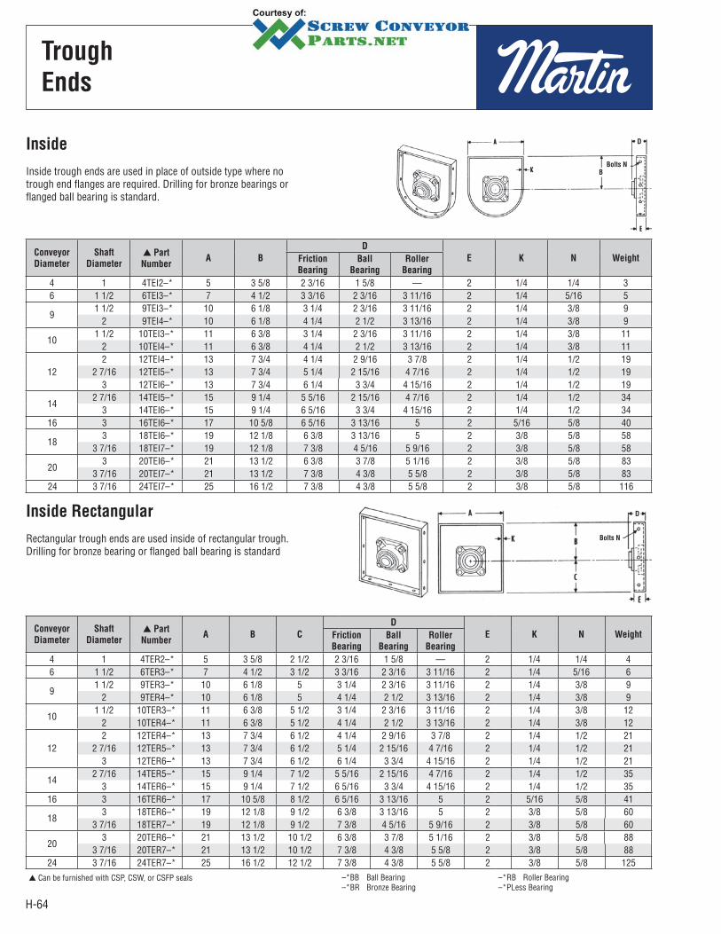
H-64
Trough
Ends
Conveyor
Diameter
Shaft
Diameter
Part
NumberA B
D
E K N WeightFriction
Bearing
Ball
Bearing
Roller
Bearing
4 1 4TEI2–* 5 3 5/8 2 3/16 1 5/8 — 2 1/4 1/4 3 6 1 1/2 6TEI3–* 7 4 1/2 3 3/16 2 3/16 3 11/16 2 1/4 5/16 5
91 1/2 9TEI3–* 10 6 1/8 3 1/4 2 3/16 3 11/16 2 1/4 3/8 9
2 9TEI4–* 10 6 1/8 4 1/4 2 1/2 3 13/16 2 1/4 3/8 9
101 1/2 10TEI3–* 11 6 3/8 3 1/4 2 3/16 3 11/16 2 1/4 3/8 11
2 10TEI4–* 11 6 3/8 4 1/4 2 1/2 3 13/16 2 1/4 3/8 11
122 12TEI4–* 13 7 3/4 4 1/4 2 9/16 3 7/8 2 1/4 1/2 19
2 7/16 12TEI5–* 13 7 3/4 5 1/4 2 15/16 4 7/16 2 1/4 1/2 19 3 12TEI6–* 13 7 3/4 6 1/4 3 3/4 4 15/16 2 1/4 1/2 19
142 7/16 14TEI5–* 15 9 1/4 5 5/16 2 15/16 4 7/16 2 1/4 1/2 34
3 14TEI6–* 15 9 1/4 6 5/16 3 3/4 4 15/16 2 1/4 1/2 34 16 3 16TEI6–* 17 10 5/8 6 5/16 3 13/16 5 2 5/16 5/8 40
183 18TEI6–* 19 12 1/8 6 3/8 3 13/16 5 2 3/8 5/8 58
3 7/16 18TEI7–* 19 12 1/8 7 3/8 4 5/16 5 9/16 2 3/8 5/8 58
203 20TEI6–* 21 13 1/2 6 3/8 3 7/8 5 1/16 2 3/8 5/8 83
3 7/16 20TEI7–* 21 13 1/2 7 3/8 4 3/8 5 5/8 2 3/8 5/8 83 24 3 7/16 24TEI7–* 25 16 1/2 7 3/8 4 3/8 5 5/8 2 3/8 5/8 116
Conveyor
Diameter
Shaft
Diameter
Part
NumberA B C
D
E K N WeightFriction
Bearing
Ball
Bearing
Roller
Bearing
4 1 4TER2–* 5 3 5/8 2 1/2 2 3/16 1 5/8 — 2 1/4 1/4 4 6 1 1/2 6TER3–* 7 4 1/2 3 1/2 3 3/16 2 3/16 3 11/16 2 1/4 5/16 6
91 1/2 9TER3–* 10 6 1/8 5 3 1/4 2 3/16 3 11/16 2 1/4 3/8 9
2 9TER4–* 10 6 1/8 5 4 1/4 2 1/2 3 13/16 2 1/4 3/8 9
101 1/2 10TER3–* 11 6 3/8 5 1/2 3 1/4 2 3/16 3 11/16 2 1/4 3/8 12
2 10TER4–* 11 6 3/8 5 1/2 4 1/4 2 1/2 3 13/16 2 1/4 3/8 12
122 12TER4–* 13 7 3/4 6 1/2 4 1/4 2 9/16 3 7/8 2 1/4 1/2 21
2 7/16 12TER5–* 13 7 3/4 6 1/2 5 1/4 2 15/16 4 7/16 2 1/4 1/2 21 3 12TER6–* 13 7 3/4 6 1/2 6 1/4 3 3/4 4 15/16 2 1/4 1/2 21
142 7/16 14TER5–* 15 9 1/4 7 1/2 5 5/16 2 15/16 4 7/16 2 1/4 1/2 35
3 14TER6–* 15 9 1/4 7 1/2 6 5/16 3 3/4 4 15/16 2 1/4 1/2 35 16 3 16TER6–* 17 10 5/8 8 1/2 6 5/16 3 13/16 5 2 5/16 5/8 41
183 18TER6–* 19 12 1/8 9 1/2 6 3/8 3 13/16 5 2 3/8 5/8 60
3 7/16 18TER7–* 19 12 1/8 9 1/2 7 3/8 4 5/16 5 9/16 2 3/8 5/8 60
203 20TER6–* 21 13 1/2 10 1/2 6 3/8 3 7/8 5 1/16 2 3/8 5/8 88
3 7/16 20TER7–* 21 13 1/2 10 1/2 7 3/8 4 3/8 5 5/8 2 3/8 5/8 88 24 3 7/16 24TER7–* 25 16 1/2 12 1/2 7 3/8 4 3/8 5 5/8 2 3/8 5/8 125
Can be furnished with CSP, CSW, or CSFP seals –*BB Ball Bearing –*BR Bronze Bearing
–*RB Roller Bearing–*P Less Bearing
Inside
Inside trough ends are used in place of outside type where no trough end flanges are required. Drilling for bronze bearings or flanged ball bearing is standard.
Bolts N
D
B
Inside Rectangular
Rectangular trough ends are used inside of rectangular trough. Drilling for bronze bearing or flanged ball bearing is standard
Bolts N
D
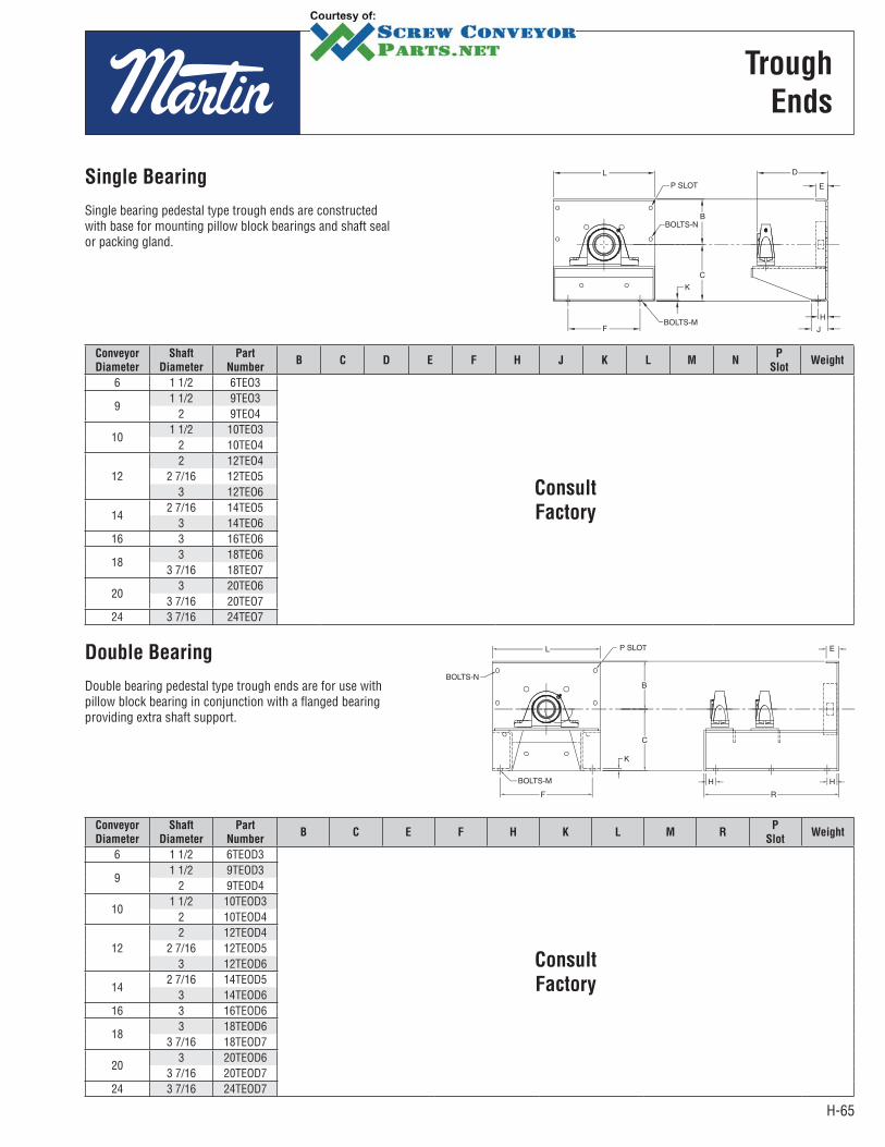
H-65
Trough
Ends
Conveyor
Diameter
Shaft
Diameter
Part
NumberB C D E F H J K L M N
P
SlotWeight
6 1 1/2 6TEO3
Consult
Factory
91 1/2 9TEO3
2 9TEO4
101 1/2 10TEO3
2 10TEO4
122 12TEO4
2 7/16 12TEO53 12TEO6
142 7/16 14TEO5
3 14TEO616 3 16TEO6
183 18TEO6
3 7/16 18TEO7
203 20TEO6
3 7/16 20TEO724 3 7/16 24TEO7
Conveyor
Diameter
Shaft
Diameter
Part
NumberB C E F H K L M R
P
SlotWeight
6 1 1/2 6TEOD3
Consult
Factory
9 1 1/2 9TEOD3
2 9TEOD4
101 1/2 10TEOD3
2 10TEOD4
122 12TEOD4
2 7/16 12TEOD53 12TEOD6
142 7/16 14TEOD5
3 14TEOD616 3 16TEOD6
183 18TEOD6
3 7/16 18TEOD7
203 20TEOD6
3 7/16 20TEOD724 3 7/16 24TEOD7
Single Bearing
Single bearing pedestal type trough ends are constructed with base for mounting pillow block bearings and shaft seal or packing gland.
Double Bearing
Double bearing pedestal type trough ends are for use with pillow block bearing in conjunction with a flanged bearing providing extra shaft support.
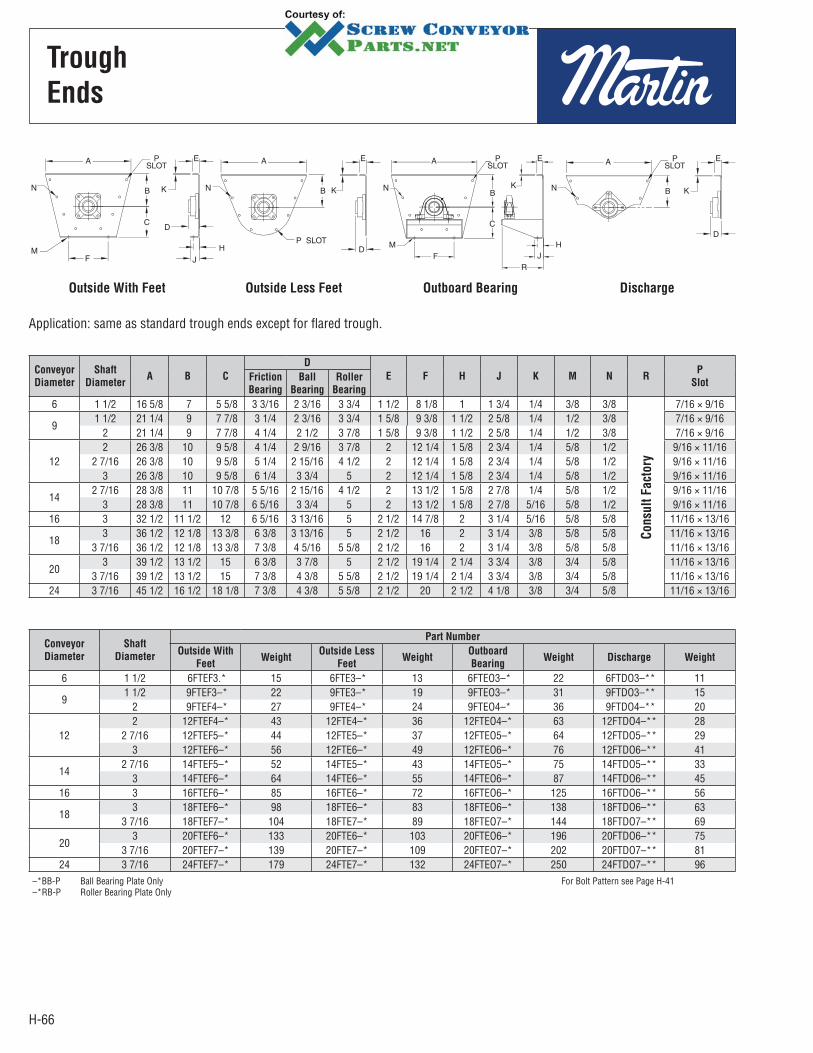
H-66
Trough
Ends
Outside With Feet Outside Less Feet Outboard Bearing Discharge
Application: same as standard trough ends except for flared trough.
Conveyor
Diameter
Shaft
DiameterA B C
D
E F H J K M N RP
SlotFriction
Bearing
Ball
Bearing
Roller
Bearing
6 1 1/2 16 5/8 7 5 5/8 3 3/16 2 3/16 3 3/4 1 1/2 8 1/8 1 1 3/4 1/4 3/8 3/8
Consu
lt F
act
ory
7/16 × 9/16
9 1 1/2 21 1/4 9 7 7/8 3 1/4 2 3/16 3 3/4 1 5/8 9 3/8 1 1/2 2 5/8 1/4 1/2 3/8 7/16 × 9/16
2 21 1/4 9 7 7/8 4 1/4 2 1/2 3 7/8 1 5/8 9 3/8 1 1/2 2 5/8 1/4 1/2 3/8 7/16 × 9/16
122 26 3/8 10 9 5/8 4 1/4 2 9/16 3 7/8 2 12 1/4 1 5/8 2 3/4 1/4 5/8 1/2 9/16 × 11/16
2 7/16 26 3/8 10 9 5/8 5 1/4 2 15/16 4 1/2 2 12 1/4 1 5/8 2 3/4 1/4 5/8 1/2 9/16 × 11/163 26 3/8 10 9 5/8 6 1/4 3 3/4 5 2 12 1/4 1 5/8 2 3/4 1/4 5/8 1/2 9/16 × 11/16
142 7/16 28 3/8 11 10 7/8 5 5/16 2 15/16 4 1/2 2 13 1/2 1 5/8 2 7/8 1/4 5/8 1/2 9/16 × 11/16
3 28 3/8 11 10 7/8 6 5/16 3 3/4 5 2 13 1/2 1 5/8 2 7/8 5/16 5/8 1/2 9/16 × 11/1616 3 32 1/2 11 1/2 12 6 5/16 3 13/16 5 2 1/2 14 7/8 2 3 1/4 5/16 5/8 5/8 11/16 × 13/16
183 36 1/2 12 1/8 13 3/8 6 3/8 3 13/16 5 2 1/2 16 2 3 1/4 3/8 5/8 5/8 11/16 × 13/16
3 7/16 36 1/2 12 1/8 13 3/8 7 3/8 4 5/16 5 5/8 2 1/2 16 2 3 1/4 3/8 5/8 5/8 11/16 × 13/16
203 39 1/2 13 1/2 15 6 3/8 3 7/8 5 2 1/2 19 1/4 2 1/4 3 3/4 3/8 3/4 5/8 11/16 × 13/16
3 7/16 39 1/2 13 1/2 15 7 3/8 4 3/8 5 5/8 2 1/2 19 1/4 2 1/4 3 3/4 3/8 3/4 5/8 11/16 × 13/1624 3 7/16 45 1/2 16 1/2 18 1/8 7 3/8 4 3/8 5 5/8 2 1/2 20 2 1/2 4 1/8 3/8 3/4 5/8 11/16 × 13/16
Conveyor
Diameter
Shaft
Diameter
Part Number
Outside With
FeetWeight
Outside Less
FeetWeight
Outboard
BearingWeight Discharge Weight
6 1 1/2 6FTEF3.* 15 6FTE3–* 13 6FTEO3–* 22 6FTDO3–** 11
9 1 1/2 9FTEF3–* 22 9FTE3–* 19 9FTEO3–* 31 9FTDO3–** 15
2 9FTEF4–* 27 9FTE4–* 24 9FTEO4–* 36 9FTDO4–** 20
122 12FTEF4–* 43 12FTE4–* 36 12FTEO4–* 63 12FTDO4–** 28
2 7/16 12FTEF5–* 44 12FTE5–* 37 12FTEO5–* 64 12FTDO5–** 293 12FTEF6–* 56 12FTE6–* 49 12FTEO6–* 76 12FTDO6–** 41
142 7/16 14FTEF5–* 52 14FTE5–* 43 14FTEO5–* 75 14FTDO5–** 33
3 14FTEF6–* 64 14FTE6–* 55 14FTEO6–* 87 14FTDO6–** 4516 3 16FTEF6–* 85 16FTE6–* 72 16FTEO6–* 125 16FTDO6–** 56
183 18FTEF6–* 98 18FTE6–* 83 18FTEO6–* 138 18FTDO6–** 63
3 7/16 18FTEF7–* 104 18FTE7–* 89 18FTEO7–* 144 18FTDO7–** 69
203 20FTEF6–* 133 20FTE6–* 103 20FTEO6–* 196 20FTDO6–** 75
3 7/16 20FTEF7–* 139 20FTE7–* 109 20FTEO7–* 202 20FTDO7–** 8124 3 7/16 24FTEF7–* 179 24FTE7–* 132 24FTEO7–* 250 24FTDO7–** 96
–*BB-P Ball Bearing Plate Only For Bolt Pattern see Page H-41–*RB-P Roller Bearing Plate Only
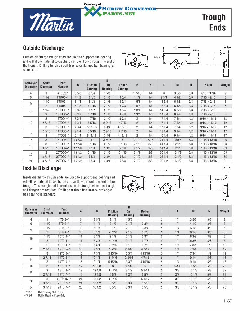
H-67
Trough
Ends
Conveyor
Diameter
Shaft
Diameter
Part
NumberB
D
E K L M N P Slot WeightFriction
Bearing
Ball
Bearing
Roller
Bearing
4 1 4TDO2.* 3 5/8 2 1/4 1 5/8 1 7/16 1/4 8 3 5/8 3/8 7/16 × 9 /16 2 6 1 1/2 6TDO3–* 4 1/2 3 1/2 2 1/8 3 3/4 1 1/2 1/4 9 3/4 4 1/2 3/8 7/16 × 9/16 3
91 1/2 9TDO3–* 6 1/8 3 1/2 2 1/8 3 3/4 1 5/8 1/4 13 3/4 6 1/8 3/8 7/16 × 9/16 5
2 9TDO4–* 6 1/8 4 7/16 2 1/2 3 7/8 1 5/8 1/4 13 3/4 6 1/8 3/8 7/16 × 9/16 5
101 1/2 10TDO3–* 6 3/8 3 1/2 2 1/8 3 3/4 1 3/4 1/4 14 3/4 6 3/8 3/8 7/16 × 9/16 6
2 10TDO4–* 6 3/8 4 7/16 2 1/2 3 7/8 1 3/4 1/4 14 3/4 6 3/8 3/8 7/16 × 9/16 6
122 12TDO4–* 7 3/4 4 7/16 2 1/2 3 7/8 2 1/4 17 1/4 7 3/4 1/2 9/16 × 11/16 12
2 7/16 12TDO5–* 7 3/4 5 5/16 2 9/16 4 7/16 2 1/4 17 1/4 7 3/4 1/2 9/16 × 11/16 12 3 12TDO6–* 7 3/4 5 15/16 3 3/4 4 15/16 2 1/4 17 1/4 7 3/4 1/2 9/16 × 11/16 12
142 7/16 14TDO5–* 9 1/4 5 5/16 2 9/16 4 7/16 2 1/4 19 1/4 9 1/4 1/2 9/16 × 11/16 17
3 14TDO6–* 9 1/4 5 15/16 3 3/8 4 15/16 2 1/4 19 1/4 9 1/4 1/2 9/16 × 11/16 17 16 3 16TDO6–* 10 5/8 6 3 7/16 5 2 1/2 5/16 21 1/4 10 5/8 5/8 11/16 × 13/16 26
183 18TDO6–* 12 1/8 6 1/16 3 1/2 5 1/16 2 1/2 3/8 24 1/4 12 1/8 5/8 11/16 × 13/16 33
3 7/16 18TDO7–* 12 1/8 6 5/8 3 3/4 5 5/8 2 1/2 3/8 24 1/4 12 1/8 5/8 11/16 × 13/16 33
203 20TDO6–* 13 1/2 6 1/16 3 1/2 5 1/16 2 1/2 3/8 26 1/4 13 1/2 5/8 11/16 × 13/16 55
3 7/16 20TDO7–* 13 1/2 6 5/8 3 3/4 5 5/8 2 1/2 3/8 26 1/4 13 1/2 5/8 11/16 × 13/16 55 24 3 7/16 24TDO7–* 16 1/2 6 5/8 3 3/4 5 5/8 2 1/2 3/8 30 1/2 16 1/2 5/8 11/16 × 13/16 81
Conveyor
Diameter
Shaft
Diameter
Part
NumberA B
D
E K M N WeightFriction
Bearing
Ball
Bearing
Roller
Bearing
4 1 4TDI2–* 5 3 5/8 2 1/4 1 5/8 2 1/4 3 5/8 3/8 2 6 1 1/2 6TDI3–* 7 4 1/2 3 1/2 2 1/8 3 3/4 2 1/4 4 1/2 3/8 3
9 1 1/2 9TDI3–* 10 6 1/8 3 1/2 2 1/8 3 3/4 2 1/4 6 1/8 3/8 5
2 9TDI4–* 10 6 1/8 4 7/16 2 1/2 3 7/8 2 1/4 6 1/8 3/8 5
101 1/2 10TDI3–* 11 6 3/8 3 1/2 2 1/8 3 3/4 2 1/4 6 3/8 3/8 6
2 10TDI4–* 11 6 3/8 4 7/16 2 1/2 3 7/8 2 1/4 6 3/8 3/8 6
122 12TDI4–* 13 7 3/4 4 7/16 2 1/2 3 7/8 2 1/4 7 3/4 1/2 12
2 7/16 12TDI5–* 13 7 3/4 5 5/16 2 9/16 4 7/16 2 1/4 7 3/4 1/2 12 3 12TDI6–* 13 7 3/4 5 15/16 3 3/4 4 15/16 2 1/4 7 3/4 1/2 12
142 7/16 14TDI5–* 15 9 1/4 5 5/16 2 9/16 4 7/16 2 1/4 9 1/4 5/8 16
3 14TDI6–* 15 9 1/4 5 15/16 3 3/8 4 15/16 2 1/4 9 1/4 5/8 16 16 3 16TDI6–* 17 10 5/8 6 3 7/16 5 2 5/16 10 5/8 5/8 25
183 18TDI6–* 19 12 1/8 6 1/16 3 1/2 5 1/16 2 3/8 12 1/8 5/8 32
3 7/16 18TDI7–* 19 12 1/8 6 5/8 3 3/4 5 5/8 2 3/8 12 1/8 5/8 32
203 20TDI16–* 21 13 1/2 6 1/16 3 1/2 5 1/16 2 3/8 13 1/2 5/8 50
3 7/16 20TDI7–* 21 13 1/2 6 5/8 3 3/4 5 5/8 2 3/8 13 1/2 5/8 50 24 3 7/16 24TDI7–* 25 16 1/2 6 5/8 3 3/4 5 5/8 2 3/8 16 1/2 5/8 76
–*BB-P Ball Bearing Plate Only–*RB-P Roller Bearing Plate Only
Outside Discharge
Outside discharge trough ends are used to support end bearing and will allow material to discharge or overflow through the end of the trough. Drilling for three bolt bronze or flanged ball bearing is standard.
P Slot
Bolts N
Inside Discharge
Inside discharge trough ends are used to support end bearing and will allow material to discharge or overflow through the end of the trough. This trough end is used inside the trough where no trough end flanges are required. Drilling for three bolt bronze or flanged ball bearing is standard.
Bolts N
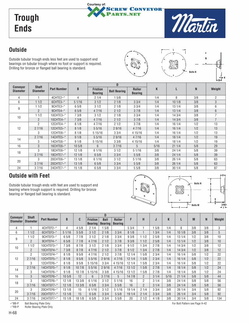
H-68
Trough
Ends
Conveyor
Diameter
Shaft
DiameterPart Number B
D
K L N WeightFriction
BearingBall Bearing
Roller
Bearing
4 1 4CHTE2–* 4 2 1/4 1 5/8 1/4 8 3/8 26 1 1/2 6CHTE3–* 5 1/16 3 1/2 2 1/8 3 3/4 1/4 10 1/8 3/8 3
91 1/2 9CHTE3–* 6 5/8 3 1/2 2 1/8 3 3/4 1/4 13 1/4 3/8 6
2 9CHTE4–* 6 5/8 4 7/16 2 1/2 3 7/8 1/4 13 1/4 3/8 6
101 1/2 10CHTE3–* 7 3/8 3 1/2 2 1/8 3 3/4 1/4 14 3/4 3/8 7
2 10CHTE4–* 7 3/8 4 7/16 2 1/2 3 7/8 1/4 14 3/4 3/8 7
122 12CHTE4–* 8 1/8 4 7/16 2 1/2 3 7/8 1/4 16 1/4 1/2 13
2 7/16 12CHTE5–* 8 1/8 5 5/16 2 9/16 4 7/16 1/4 16 1/4 1/2 133 12CHTE6–* 8 1/8 5 15/16 3 3/4 4 15/16 1/4 16 1/4 1/2 13
142 7/16 14CHTE5–* 9 1/8 5 5/16 2 9/16 4 7/16 1/4 18 1/4 1/2 19
3 14CHTE6–* 9 1/8 5 15/16 3 3/8 4 15/16 1/4 18 1/4 1/2 1916 3 16CHTE6–* 10 5/8 6 3 7/16 5 5/16 21 1/4 5/8 29
183 18CHTE6–* 12 1/8 6 1/16 3 1/2 5 1/16 3/8 24 1/4 5/8 39
3 7/16 18CHTE7–* 12 1/8 6 5/8 3 3/4 5 5/8 3/8 24 1/4 5/8 39
203 20CHTE6–* 13 1/8 6 1/16 3 1/2 5 1/16 3/8 26 1/4 5/8 63
3 7/16 20CHTE7–* 13 1/8 6 5/8 3 3/4 5 5/8 3/8 26 1/4 5/8 6324 3 7/16 24CHTE7–* 15 1/8 6 5/8 3 3/4 5 5/8 3/8 30 1/4 5/8 87
Conveyor
Diameter
Shaft
DiameterPart Number B C
D
F H J K L M N WeightFriction
Bearing
Ball
Bearing
Roller
Bearing
4 1 4CHTEF2–* 4 4 5/8 2 1/4 1 5/8 5 3/4 1 1 5/8 1/4 8 3/8 3/8 36 1 1/2 6CHTEF3–* 5 1/16 5 5/8 3 1/2 2 1/8 3 3/4 8 1/8 1 1 3/4 1/4 10 1/8 3/8 3/8 5
91 1/2 9CHTEF3–* 6 5/8 7 7/8 3 1/2 2 1/8 3 3/4 9 3/8 1 1/2 2 5/8 1/4 13 1/4 1/2 3/8 10
2 9CHTEF4–* 6 5/8 7 7/8 4 7/16 2 1/2 3 7/8 9 3/8 1 1/2 2 5/8 1/4 13 1/4 1/2 3/8 10
101 1/2 10CHTEF3–* 7 3/8 8 7/8 3 1/2 2 1/8 3 3/4 9 1/2 1 3/4 2 7/8 1/4 14 3/4 1/2 3/8 12
2 10CHTEF4–* 7 3/8 8 7/8 4 7/16 2 1/2 3 7/8 9 1/2 1 3/4 2 7/8 1/4 14 3/4 1/2 3/8 12
122 12CHTEF4–* 8 1/8 9 5/8 4 7/16 2 1/2 3 7/8 12 1/4 1 5/8 2 3/4 1/4 16 1/4 5/8 1/2 22
2 7/16 12CHTEF5–* 8 1/8 9 5/8 5 5/16 2 9/16 4 7/16 12 1/4 1 5/8 2 3/4 1/4 16 1/4 5/8 1/2 223 12CHTEF6–* 8 1/8 9 5/8 5 15/16 3 3/4 4 15/16 12 1/4 1 5/8 2 3/4 1/4 16 1/4 5/8 1/2 22
142 7/16 14CHTEF5–* 9 1/8 10 7/8 5 5/16 2 9/16 4 7/16 13 1/2 1 5/8 2 7/8 1/4 18 1/4 5/8 1/2 24
3 14CHTEF6–* 9 1/8 10 7/8 5 15/16 3 3/8 4 15/16 13 1/2 1 5/8 2 7/8 1/4 18 1/4 5/8 1/2 2416 3 16CHTEF6–* 10 5/8 12 6 3 7/16 5 14 7/8 2 3 1/4 5/16 21 1/4 5/8 5/8 44
183 18CHTEF6–* 12 1/8 13 3/8 6 1/16 3 1/2 5 1/16 16 2 3 1/4 3/8 24 1/4 5/8 5/8 56
3 7/16 18CHTEF7–* 12 1/8 13 3/8 6 5/8 3 3/4 5 5/8 16 2 3 1/4 3/8 24 1/4 5/8 5/8 56
203 20CHTEF6–* 13 1/8 15 6 1/16 3 1/2 5 1/16 19 1/4 2 1/4 3 3/4 3/8 26 1/4 3/4 5/8 92
3 7/16 20CHTEF7–* 13 1/8 15 6 5/8 3 3/4 5 5/8 19 1/4 2 1/4 3 3/4 3/8 26 1/4 3/4 5/8 9224 3 7/16 24CHTEF7–* 15 1/8 18 1/8 6 5/8 3 3/4 5 5/8 20 2 1/2 4 1/8 3/8 30 1/4 3/4 5/8 134
–*BB-P Ball Bearing Plate Only For Bolt Pattern see Page H-42–*RB-P Roller Bearing Plate Only
Outside
Outside tubular trough ends less feet are used to support end bearings on tubular trough where no foot or support is required. Drilling for bronze or flanged ball bearing is standard.
Bolts N
Outside with Feet
Outside tubular trough ends with feet are used to support end bearing where trough support is required. Drilling for bronze bearing or flanged ball bearing is standard.
Bolts N
Bolts M

H-69
Saddles — Feet
Trough End Flanges
Conveyor DiameterPart Number Weight
Saddle Tubular Flange Foot Saddle Tubular Flange Foot
4 4TS 4CHTFF 4TFF 1.5 1 1.56 6TS 6CHTFF 6TFF 2.0 2 2.09 9TS 9CHTFF 9TFF 4.5 4.5 4.510 10TS 10CHTFF 10TFF 5.0 4.5 5.012 12TS 12CHTFF 12TFF 6.0 5 6.014 14TS 14CHTFF 14TFF 7.0 7 7.016 16TS 16CHTFF 16TFF 8.0 8 7.518 18TS 18CHTFF 18TFF 10.0 10 9.520 20TS 20CHTFF 20TFF 13.0 11 12.524 24TS 24CHTFF 24TFF 15.0 12 14.5
Conveyor
DiameterC E F G H J K M* N
4 4 5/8 1 7/16 5 3/4 7 3/8 1 1 5/8 3/16 3/8 3/86 5 5/8 1 7/16 8 1/8 10 1 1/4 2 3/16 3/8 3/89 7 7/8 1 3/4 9 3/8 12 1 1/2 2 5/8 3/16 1/2 3/8
10 8 7/8 1 3/4 9 1/2 12 3/8 1 3/4 2 7/8 3/16 1/2 3/812 9 5/8 1 3/4 12 1/4 15 1 5/8 2 3/4 1/4 5/8 1/214 10 7/8 2 13 1/2 16 1/2 1 5/8 2 7/8 1/4 5/8 1/216 12 2 14 7/8 18 2 3 1/4 1/4 5/8 5/818 13 3/8 2 16 19 1/8 2 3 1/4 1/4 5/8 5/820 15 2 1/2 19 1/4 22 3/4 2 1/4 3 3/4 1/4 3/4 5/824 18 1/8 2 1/2 20 24 2 1/2 4 1/4 3/4 5/8
* Holes for Bolt M Slotted
Flange Foot
SizePart
Number
A
B K L N Weight
Red Rubber
GasketTrough Thickness
Thru 10 Ga. 3/16 & 1/4 Part Number
4 4TF* 5 1/4 5 3/8 3 3/8 1/4 1 1/4 3/8 .09 4TFG6 6TF* 7 1/4 7 3/8 4 1/4 1/4 1 1/2 3/8 1.5 6TFG9 9TF* 10 1/4 10 1/2 5 7/8 1/4 13/4 3/8 2.4 9TFG10 10TF* 11 1/4 11 1/2 6 1/8 1/4 13/4 3/8 2.6 10TFG12 12TF* 13 1/4 13 1/2 7 1/2 1/4 2 1/2 5.6 12TFG14 14TF* 15 1/4 15 1/2 9 1/4 2 1/2 6.5 14TFG16 16TF* 17 1/4 17 1/2 10 3/8 1/4 2 5/8 7.4 16TFG18 18TF* 19 1/4 19 1/2 11 13/16 1/4 2 1/2 5/8 10.2 18TFG20 20TF* 21 1/4 21 1/2 13 3/16 1/4 2 1/2 5/8 11.3 20TFG24 24TF* 25 1/4 25 1/2 16 1/2 1/4 2 1/2 5/8 15.5 24TFG
*–10 used for troughs through 10 ga., –3 used for troughs 3/16 and 1/4 thick.*** For White Rubber Gasket Add WN
Flange Foot
Trough feet are used to support trough at trough connections.
Saddle
Trough saddles are used to support trough where flange feet cannot be used at connections
Bolts N
Bolts M
KAL
B
N
2
A
Bolts M

H-70
End
Bearing
KEEP THE HOUSING REPLACE THE INSERT.
TEBH- Split Bearing Housings will help cut down on a plant’s repair parts inventory, as well as the cost of the bearing. The rugged cast iron housing is not subject to wear, only the Style 220 Hanger bearing insert needs to be replaced.
The housings match CEMA standard ball bearing bolt pattern, so they can be used with most seals.
Split bearing housings are stocked in all stocking facilities. Call your distributor for more information.
TROUGH END BEARING HOUSINGS
Split Bearing Housings utilize Style 220 Hanger Bearings.
FLA
NG
E U
NIT
S
Mounted on trough end plate
Ball Bearing
Flange Unit
Roller Bearing
Flange Unit
Bronze Sleeve Bearing
Flange Unit
PIL
LO
W B
LO
CK
S
Mounted on pedestal of outboard bearing trough end.
Ball Bearing
Pillow Block
Roller Bearing
Pillow Block
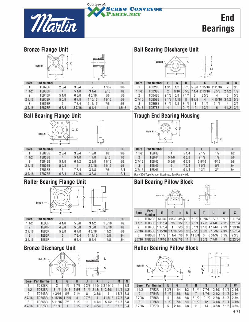
H-71
Bronze Flange Unit
Bore Part Number C D E G N
1 TEB2BR 2 3/4 3 3/4 2 17/32 3/81 1/2 TEB3BR 4 5 1/8 3 1/4 9/16 1/2
2 TEB4BR 5 1/8 6 3/8 4 3/16 5/8 5/82 7/16 TEB5BR 5 5/8 6 7/8 4 15/16 13/16 5/8
3 TEB6BR 6 7 3/4 5 11/16 7/8 5/83 7/16 TEB7BR 6 3/4 8 7/16 6 1/4 1 13/16
Ball Bearing Flange Unit
Bore Part Number C D E G N
1 TEB2BB 2 3/4 3 3/4 1 3/8 1/2 3/81 1/2 TEB3BB 4 5 1/8 1 7/8 9/16 1/2
2 TEB4BB 5 1/8 6 1/2 2 3/8 11/16 5/82 7/16 TEB5BB 5 5/8 7 2 5/16 11/16 5/8
3 TEB6BB 6 7 3/4 3 1/8 7/8 3/43 7/16 TEB7BB 6 3/4 8 7/16 3 3/8 1 3/4
Roller Bearing Flange Unit
C
C
D
D EG
N
Bore Part Number C D E G N
1 1/2 TEB3R 4 1/8 5 3/8 3 1/2 1 3/16 1/22 TEB4R 4 3/8 5 5/8 3 5/8 1 3/16 1/2
2 7/16 TEB5R 5 3/8 6 7/8 4 3/16 1 1/2 5/83 TEB6R 6 7 3/4 4 11/16 1 5/8 3/4
3 7/16 TEB7R 7 9 1/4 5 1/4 1 7/8 3/4
Bronze Discharge Unit
Bore Part Number E G H J K L M N
1 TDB2BR 2 1/2 3 7/8 5 3/8 1 15/16 2 11/16 1 3/8 1 1/2 TDB3BR 3 1/4 9/16 5 5/8 7 1/4 2 13/16 3 5/8 1 1/4 1/2
2 TDB4BR 4 3/16 5/8 7 1/4 8 3 5/8 4 1 5/8 5/8 2 7/16 TDB5BR 4 15/16 11/16 8 9 7/8 4 4 15/16 1 7/8 5/8
3 TDB6BR 5 11/16 7/8 8 1/2 11 4 1/4 5 1/2 2 1/8 5/8 3 7/16 TDB7BR 6 1/4 1 9 1/2 12 4 3/4 6 2 1/2 3/4
Ball Bearing Pillow Block
BorePart
NumberE G N R S T U W X
1 TPB2BB 51/64 19/32 3/8 4 1/8 5 1/2 1 1/16 2 13/16 1 7/16 1 11/64 1 1/2 TPB3BB 1 11/64 7/8 1/2 5 1/2 7 1/4 1 7/8 4 1/8 2 1/8 1 21/64
2 TPB4BB 1 17/64 1 5/8 6 3/8 8 1/4 2 1/8 4 17/64 2 1/4 1 13/16 2 7/16 TPB5BB 1 15/16 1 1/16 5/8 7 3/8 9 5/8 2 3/8 5 15/32 2 3/4 1 57/64
3 TPB6BB 1 1/2 1 1/4 7/8 9 11 3/4 3 6 31/32 3 1/2 2 3/8 3 7/16 TPB7BB 1 9/16 1 11/32 7/8 11 14 3 3/8 7 7/8 4 2 23/64
Roller Bearing Pillow Block
Bore Part Number E G N R S T U W
1 1/2 TPB3R 3 3/8 1 1/4 1/2 6 1/4 7 7/8 2 3/8 4 1/4 2 1/8 2 TPB4R 3 1/2 1 3/8 5/8 7 8 7/8 2 1/2 4 1/2 2 1/4
2 7/16 TPB5R 4 1 5/8 5/8 8 1/2 10 1/2 2 7/8 5 1/2 2 3/43 TPB6R 4 1/2 1 7/8 3/4 9 1/2 12 3 1/8 6 1/4 3 1/8
3 7/16 TPB7R 5 2 1/4 7/8 11 14 3 5/8 7 1/2 3 3/4
Ball Bearing Discharge Unit
Bore Part Number E G H J K L M N
1 TDB2BB 1 3/8 1/2 3 7/8 5 3/8 1 15/16 2 11/16 2 3/8 1 1/2 TDB3BB 2 9/16 5 5/8 7 1/4 2 13/16 3 5/8 2 1/2 1/2
2 TDB4BB 2 1/8 5/8 7 1/4 8 3 5/8 4 3 5/8 2 7/16 TDB5BB 2 1/2 11/16 8 9 7/8 4 4 15/16 3 1/2 5/8
3 TDB6BB 3 1/2 7/8 8 1/2 11 4 1/4 5 1/2 4 3/4 3 7/16 TDB7BB 4 1 9 1/2 12 4 3/4 6 4 1/2 3/4
Trough End Bearing Housing
N
C
C
D
D
GE
Bore Part Number C D E G N
1 1/2 TEBH3 4 5 1/4 2 1/2 1/2 1/22 TEBH4 5 1/8 6 3/8 2 1/2 1/2 5/8
2 7/16 TEBH5 5 5/8 6 7/8 3 9/16 9/16 5/83 TEBH6 6 7 3/4 3 5/8 5/8 3/4
3 7/16 TEBH7 7 9 1/4 4 3/4 3/4 3/4Use #220 Type Hanger Bearings, See Page H-92.
Bolts N
Bolts N
Bolts N
Bolts N
Bolts N
Bolts N
Bolts N
End
Bearings
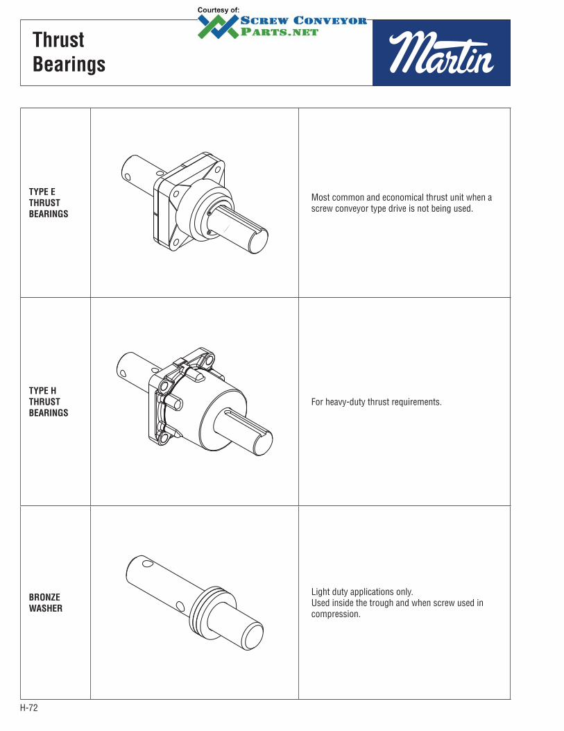
H-72
Thrust
Bearings
TYPE E
THRUST
BEARINGS
Most common and economical thrust unit when a screw conveyor type drive is not being used.
TYPE H
THRUST
BEARINGS
For heavy-duty thrust requirements.
BRONZE
WASHER
Light duty applications only.Used inside the trough and when screw used in compression.
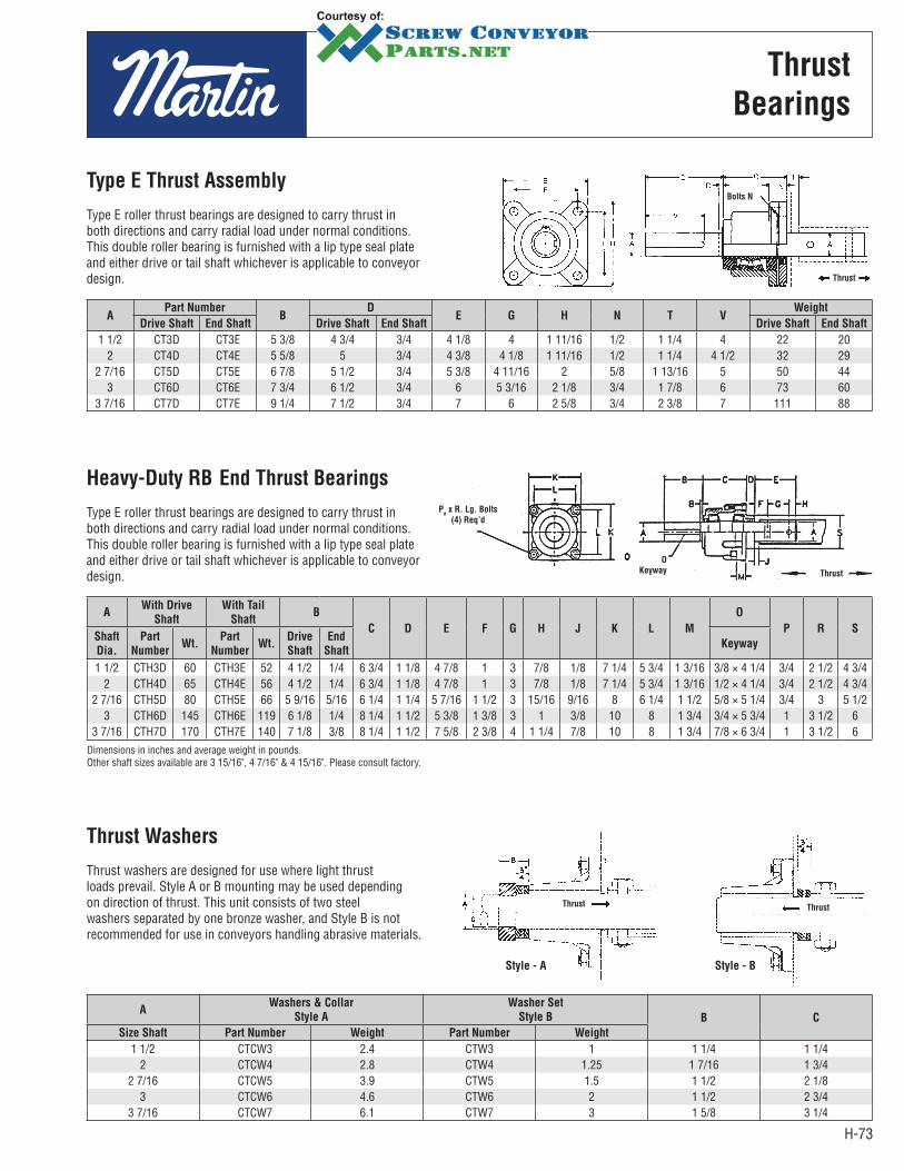
H-73
Thrust
Bearings
APart Number
BD
E G H N T VWeight
Drive Shaft End Shaft Drive Shaft End Shaft Drive Shaft End Shaft
1 1/2 CT3D CT3E 5 3/8 4 3/4 3/4 4 1/8 4 1 11/16 1/2 1 1/4 4 22 20 2 CT4D CT4E 5 5/8 5 3/4 4 3/8 4 1/8 1 11/16 1/2 1 1/4 4 1/2 32 29
2 7/16 CT5D CT5E 6 7/8 5 1/2 3/4 5 3/8 4 11/16 2 5/8 1 13/16 5 50 44 3 CT6D CT6E 7 3/4 6 1/2 3/4 6 5 3/16 2 1/8 3/4 1 7/8 6 73 60
3 7/16 CT7D CT7E 9 1/4 7 1/2 3/4 7 6 2 5/8 3/4 2 3/8 7 111 88
Type E Thrust Assembly
Type E roller thrust bearings are designed to carry thrust in both directions and carry radial load under normal conditions. This double roller bearing is furnished with a lip type seal plate and either drive or tail shaft whichever is applicable to conveyor design. Thrust
Bolts N
AWith Drive
Shaft
With Tail
ShaftB
C D E F G H J K L M
O
P R SShaft
Dia.
Part
NumberWt.
Part
NumberWt.
Drive
Shaft
End
ShaftKeyway
1 1/2 CTH3D 60 CTH3E 52 4 1/2 1/4 6 3/4 1 1/8 4 7/8 1 3 7/8 1/8 7 1/4 5 3/4 1 3/16 3/8 × 4 1/4 3/4 2 1/2 4 3/42 CTH4D 65 CTH4E 56 4 1/2 1/4 6 3/4 1 1/8 4 7/8 1 3 7/8 1/8 7 1/4 5 3/4 1 3/16 1/2 × 4 1/4 3/4 2 1/2 4 3/4
2 7/16 CTH5D 80 CTH5E 66 5 9/16 5/16 6 1/4 1 1/4 5 7/16 1 1/2 3 15/16 9/16 8 6 1/4 1 1/2 5/8 × 5 1/4 3/4 3 5 1/23 CTH6D 145 CTH6E 119 6 1/8 1/4 8 1/4 1 1/2 5 3/8 1 3/8 3 1 3/8 10 8 1 3/4 3/4 × 5 3/4 1 3 1/2 6
3 7/16 CTH7D 170 CTH7E 140 7 1/8 3/8 8 1/4 1 1/2 7 5/8 2 3/8 4 1 1/4 7/8 10 8 1 3/4 7/8 × 6 3/4 1 3 1/2 6Dimensions in inches and average weight in pounds.Other shaft sizes available are 3 15/16", 4 7/16" & 4 15/16". Please consult factory.
Heavy-Duty RB End Thrust Bearings
Type E roller thrust bearings are designed to carry thrust in both directions and carry radial load under normal conditions. This double roller bearing is furnished with a lip type seal plate and either drive or tail shaft whichever is applicable to conveyor design. Thrust
O
Keyway
Pø x R. Lg. Bolts
(4) Req’d
AWashers & Collar
Style A
Washer Set
Style B B C
Size Shaft Part Number Weight Part Number Weight
1 1/2 CTCW3 2.4 CTW3 1 1 1/4 1 1/42 CTCW4 2.8 CTW4 1.25 1 7/16 1 3/4
2 7/16 CTCW5 3.9 CTW5 1.5 1 1/2 2 1/8 3 CTCW6 4.6 CTW6 2 1 1/2 2 3/4
3 7/16 CTCW7 6.1 CTW7 3 1 5/8 3 1/4
Thrust Washers
Thrust washers are designed for use where light thrust loads prevail. Style A or B mounting may be used depending on direction of thrust. This unit consists of two steel washers separated by one bronze washer, and Style B is not recommended for use in conveyors handling abrasive materials.
Thrust
Style - BStyle - A
Thrust

H-74
Shaft
Seals
WASTE
PACK
SEAL
Waste pack seals can be furnished with waste packing or in combination with lip seal. This type seal is normally installed between the trough end and bearing, but may be used separately on pedestal type trough ends. An opening is provided at top for repacking without removing seal from trough end. Can be used with flanged ball, roller or other standard 4-bolt bearings.
SUPER
PACK SEAL
Super Pack Seal combines the heavy duty waste pack housing with the superior sealing characteristics of a Super Pack Seal. Seal may also be air or grease purged for difficult sealing applications.
PRODUCT
DROP OUT
SEAL
This flange type dust seal is designed for insertion between trough end and flanged ball bearing. The cast iron housing is open on all four sides for exit of material that might work past seal or lubricant from bearing.
PLATE
SEAL
Plate seals are the most common and economical seal. It is normally furnished with a lip seal. This type seal is normally installed between the trough end and bearing, but may be used separately on pedestal type trough ends. Can be used with flanged ball, roller or other standard 4-bolt bearings.
SPLIT
GLAND
SEAL
Split gland compression type seals provide for easy replacement and adjustment of packing pressure on the shaft without removal of the conveyor. These seals can be installed inside or outside the end plates.
COMPRESSION
TYPE PACKING
GLAND SEAL
Flanged packing gland seals consist of an external housing and an internal gland which is forced into the housing to compress the packing. This is the most positive type shaft seal and may be used where minor pressure requirements are desired.
AIR-PURGED
SEAL
Air purge shaft seals are arranged for attaching to standard or special trough ends. A constant air pressure is maintained to prevent material from escaping from the trough along the shaft. The air purge seal is desirable for sealing highly abrasive materials. May be purged with grease or water.
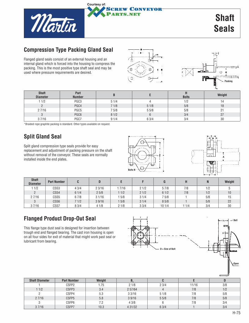
H-75
Shaft
Seals
Shaft
Diameter
Part
NumberB E
H
BoltsWeight
1 1/2 PGC3 5 1/4 4 1/2 142 PGC4 7 1/8 5 1/8 5/8 18
2 7/16 PGC5 7 5/8 5 5/8 5/8 213 PGC6 8 1/2 6 3/4 27
3 7/16 PGC7 9 1/4 6 3/4 3/4 30*Braided rope graphite packing is standard. Other types available on request.
Compression Type Packing Gland Seal
Flanged gland seals consist of an external housing and an internal gland which is forced into the housing to compress the packing. This is the most positive type shaft seal and may be used where pressure requirements are de sired.
Packing
Shaft
DiameterPart Number C D E F G H N Weight
1 1/2 CSS3 4 3/4 2 3/16 1 7/16 2 1/2 5 7/8 7/8 1/2 5 2 CSS4 6 1/4 2 5/8 1 1/2 2 1/2 6 1/2 7/8 1/2 10
2 7/16 CSS5 6 7/8 3 1/16 1 5/8 3 1/4 7 5/8 1 5/8 15 3 CSS6 7 1/2 3 9/16 1 5/8 3 1/4 8 5/8 1 5/8 22
3 7/16 CSS7 8 3/4 4 1/8 2 1/8 3 3/4 10 1/4 1 1/4 3/4 30
Split Gland Seal
Split gland compression type seals provide for easy replacement and adjustment of packing pressure on the shaft without removal of the conveyor. These seals are normally installed inside the end plates.
Bolts N
Shaft Diameter Part Number Weight B1
C E D
1 CSFP2 1.75 2 1/8 2 3/4 11/16 3/8 1 1/2 CSFP3 3.4 2 57/64 4 7/8 1/2
2 CSFP4 5.3 3 3/16 5 1/8 7/8 5/82 7/16 CSFP5 5.8 3 9/16 5 5/8 7/8 5/8
3 CSFP6 7.2 4 3/8 6 7/8 3/4 3 7/16 CSFP7 10.3 4 31/32 6 3/4 1 3/4
Flanged Product Drop-Out Seal
This flange type dust seal is designed for insertion between trough end and flanged bearing. The cast iron housing is open on all four sides for exit of material that might work past seal or lubricant from bearing.
D = Size of Bolt
Ball
Open
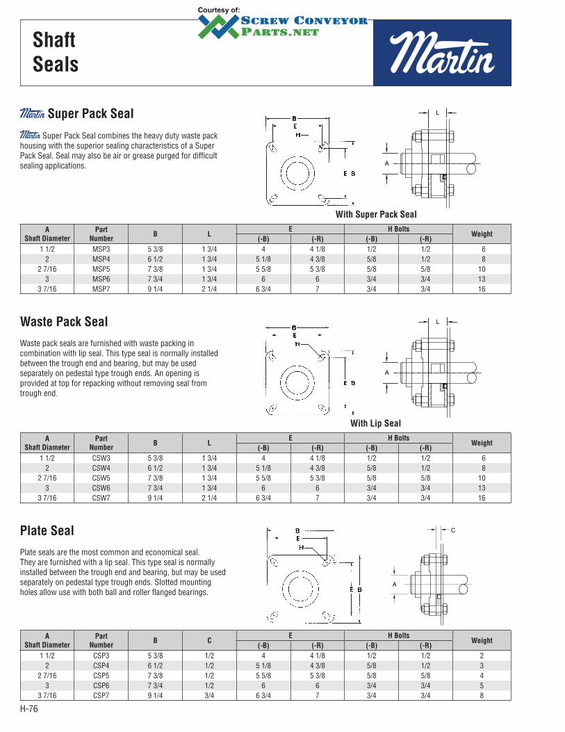
H-76
Shaft
Seals
A
Shaft Diameter
Part
NumberB L
E H BoltsWeight
(-B) (-R) (-B) (-R)
1 1/2 MSP3 5 3/8 1 3/4 4 4 1/8 1/2 1/2 62 MSP4 6 1/2 1 3/4 5 1/8 4 3/8 5/8 1/2 8
2 7/16 MSP5 7 3/8 1 3/4 5 5/8 5 3/8 5/8 5/8 103 MSP6 7 3/4 1 3/4 6 6 3/4 3/4 13
3 7/16 MSP7 9 1/4 2 1/4 6 3/4 7 3/4 3/4 16
Super Pack Seal
Super Pack Seal combines the heavy duty waste pack housing with the superior sealing characteristics of a Super Pack Seal. Seal may also be air or grease purged for difficult sealing applications.
With Super Pack Seal
A
Shaft Diameter
Part
NumberB L
E H BoltsWeight
(-B) (-R) (-B) (-R)
1 1/2 CSW3 5 3/8 1 3/4 4 4 1/8 1/2 1/2 62 CSW4 6 1/2 1 3/4 5 1/8 4 3/8 5/8 1/2 8
2 7/16 CSW5 7 3/8 1 3/4 5 5/8 5 3/8 5/8 5/8 103 CSW6 7 3/4 1 3/4 6 6 3/4 3/4 13
3 7/16 CSW7 9 1/4 2 1/4 6 3/4 7 3/4 3/4 16
Waste Pack Seal
Waste pack seals are furnished with waste packing in combination with lip seal. This type seal is normally installed between the trough end and bearing, but may be used separately on pedestal type trough ends. An opening is provided at top for repacking without removing seal from trough end.
With Lip Seal
A
Shaft Diameter
Part
NumberB C
E H BoltsWeight
(-B) (-R) (-B) (-R)
1 1/2 CSP3 5 3/8 1/2 4 4 1/8 1/2 1/2 22 CSP4 6 1/2 1/2 5 1/8 4 3/8 5/8 1/2 3
2 7/16 CSP5 7 3/8 1/2 5 5/8 5 3/8 5/8 5/8 43 CSP6 7 3/4 1/2 6 6 3/4 3/4 5
3 7/16 CSP7 9 1/4 3/4 6 3/4 7 3/4 3/4 8
Plate Seal
Plate seals are the most common and economical seal. They are furnished with a lip seal. This type seal is normally installed between the trough end and bearing, but may be used separately on pedestal type trough ends. Slotted mounting holes allow use with both ball and roller flanged bearings.
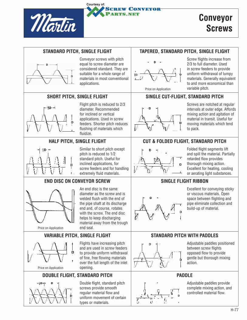
H-77
STANDARD PITCH, SINGLE FLIGHT TAPERED, STANDARD PITCH, SINGLE FLIGHT
Conveyor screws with pitch equal to screw diameter are considered standard. They are suitable for a whole range of materials in most conventional applications.
Screw flights increase from 2/3 to full diameter. Used in screw feeders to provide uniform withdrawal of lumpy materials. Generally equivalent to and more economical than variable pitch.Price on Application
SHORT PITCH, SINGLE FLIGHT SINGLE CUT-FLIGHT, STANDARD PITCH
Flight pitch is reduced to 2/3 diameter. Recommended for inclined or vertical applications. Used in screw feeders. Shorter pitch reduces flushing of materials which fluidize.
Screws are notched at regular intervals at outer edge. Affords mixing action and agitation of material in transit. Useful for moving materials which tend to pack.
HALF PITCH, SINGLE FLIGHT CUT & FOLDED FLIGHT, STANDARD PITCH
Similar to short pitch except pitch is reduced to 1/2 standard pitch. Useful for inclined applications, for screw feeders and for handling extremely fluid materials.
Folded flight segments lift and spill the material. Partially retarded flow provides thorough mixing action. Excellent for heating, cooling or aerating light substances.
END DISC ON CONVEYOR SCREW SINGLE FLIGHT RIBBON
An end disc is the same diameter as the screw and is welded flush with the end of the pipe shaft at its discharge end and, of course, rotates with the screw. The end disc helps to keep discharging material away from the trough end seal.
Excellent for conveying sticky or viscous materials. Open space between flighting and pipe eliminate collection and build-up of material.
Price on Application
VARIABLE PITCH, SINGLE FLIGHT STANDARD PITCH WITH PADDLES
Flights have increasing pitch and are used in screw feeders to provide uniform withdrawal of fine, free flowing materials over the full length of the inlet opening.
Adjustable paddles positioned between screw flights opposed flow to provide gentle but thorough mixing action.
Price on Application
DOUBLE FLIGHT, STANDARD PITCH PADDLE
Double flight, standard pitch screws provide smooth regular material flow and uniform movement of certain types or materials.
Adjustable paddles provide complete mixing action, and controlled material flow.
Conveyor
Screws

H-78
Conveyor
Screws
Helicoid flights are formed in a special rolling machine by forming a steel strip into a continuous one-piece helix of the desired diameter, pitch and thickness to fit conveyor screw pipes. The helicoid flight is tapered in cross section, with the thickness at the inner edge approximately twice the thickness of the outer edge.
Sectional flights are individual flights or turns blanked from steel plates and formed into a spiral or helix of the desired diameter and pitch to fit conveyor screw pipes. The flights are butt welded together to form a continuous conveyor screw. Modifications can be furnished, such as, fabrication from various metals, different flight thicknesses, other diameters and pitches. The buttweld flight is the same thickness in the full cross section.
Key to Conveyor Size Designation
The letter “H” indicates screw conveyor with helicoid flighting. The figures to the left of the letters indicate the nominal outside diameter of the conveyor in inches. The first figure following the letters is twice the diameter of the couplings in inches. The last two figures indicate the nominal thickness of flighting at the outer edge in 1/64". Thus conveyor 12H408 indicates 12" diameter helicoid conveyor for 2" couplings with flighting 8/64" or 1/8" thickness at outer edge. Hand of conveyor is indicated by “R” or “L” following the designation.
Helicoid Flight Sectional Flight
Comparison Table • helicoid flight and sectional flight conveyor screws
Screw
Diameter
Helicoid Flight Sectional Flight
Conveyor
Screw Size
Designation
Former
Designation
Coupling
Diameter
Nominal
Inside
Diameter of
Pipe
Thickness of Flight Conveyor
Screw Size
Designation
Coupling
Diameter
Nominal
Inside
Diameter of
Pipe
Thickness of
FlightInner Edge Outer Edge
4 4H206 4 X 1 1 3/8 3/16 3/32 – – – –
66H304 6 Standard 1 1/2 2 1/8 1/16 – – – –6H308 6 X 1 1/2 2 1/4 1/8 6S309 1 1/2 2 10 ga.6H312 6 XX 1 1/2 2 3/8 3/16 6S312 1 1/2 2 3/16 in.
9
9H306 9 Standard 1 1/2 2 3/16 3/32 9S307 1 1/2 2 12 ga.9H406 9 Special 2 2 1/2 3/16 3/32 9S407 2 2 1/2 12 ga.9H312 9 X 1 1/2 2 3/8 3/16 9S312 1 1/2 2 3/16 in.9H412 9 XX 2 2 1/2 3/8 3/16 9S412 2 2 1/2 3/16 in.9H414 — 2 2 1/2 7/16 7/32 9S416 2 2 1/2 1/4 in.
1010H306 10 Standard 1 1/2 2 3/16 3/32 10S309 1 1/2 2 10 ga.10H412 10 XX 2 2 1/2 3/8 3/16 10S412 2 2 1/2 3/16 in.
12
12H408 12 Standard 2 2 1/2 1/4 1/8 12S409 2 2 1/2 10 ga.12H508 12 Special 2 7/16 3 1/4 1/8 12S509 2 7/16 3 10 ga.12H412 12 X 2 2 1/2 3/8 3/16 12S412 2 2 1/2 3/16 in.12H512 12 XX 2 7/16 3 3/8 3/16 12S512 2 7/16 3 3/16 in.12H614 — 3 3 1/2 7/16 7/32 12S616 3 3 1/2 1/4 in.
1414H508 14 Standard 2 7/16 3 1/4 1/8 14S509 2 7/16 3 10 ga.14H614 14 XX 3 3 1/2 7/16 7/32 14S616 3 3 1/2 1/4 in.
1616H610 16 Standard 3 3 1/2 5/16 5/32 16S609 3 3 1/2 10 ga.16H614 — 3 4 7/16 7/32 16S616 3 3 1/2 1/4 in.
Size designation: Examples: 12H412 and 12S412. 12 = screw diameter in inches H = helicoid flight S = sectional flight 4 = 2 times 2" coupling diameter 12 = thickness of flight at periphery in increments of 1/64"

H-79
Conveyor Screws
(Helicoid)
Length Length
Helicoid Conveyor Screw Flighting
A B Size
Part No.
Conveyor
Mounted
Size
Part No.
Flighting
Only
D
Pipe Size
Flight
Thickness
H Standard
Length
Feet –
Inches
Average Weight
Screw
Diameter
Coupling
Diameter
Coupling
Bearing
Length
Complete Screw Flighting Only
Nominal
InsideOutside
F G Standard
Length
Per
Foot
Standard
Length
Per
FootInside Outside
4 1 4H206–* 4HF206–* 1 3/8 1 5/8 3/16 3/32 1 1/2 9 – 10 1/2 40 4 16 1.3
61 1/2 6H304–* 6HF304–* 2 2 3/8 1/8 1/16 2 9 – 10 52 5 14 1.4 1 1/2 6H308–* 6HF308–* 2 2 3/8 1/4 1/8 2 9 – 10 62 6 28 2.8 1 1/2 6H312–* 6HF312–* 2 2 3/8 3/8 3/16 2 9 – 10 72 7 42 4.3
9
1 1/2 9H306–* 9HF306–* 2 2 3/8 3/16 3/32 2 9 – 10 70 7 31 3.2 1 1/2 9H312–* 9HF312–* 2 2 3/8 3/8 3/16 2 9 – 10 101 10 65 6.1
2 9H406–* 9HF406–* 2 1/2 2 7/8 3/16 3/32 2 9 – 10 91 9 30 3.0 2 9H412–* 9HF412–* 2 1/2 2 7/8 3/8 3/16 2 9 – 10 121 12 60 6.6 2 9H414–* 9HF414–* 2 1/2 2 7/8 7/16 7/32 2 9 – 10 131 13 70 6.3
101 1/2 10H306–* 10HF306–* 2 2 3/8 3/16 3/32 2 9 – 10 81 8 48 4.9
2 10H412–* 10HF412–* 2 1/2 2 7/8 3/8 3/16 2 9 – 10 130 13 76 7.7
12
2 12H408–* 12HF408–* 2 1/2 2 7/8 1/4 1/8 2 11 – 10 140 12 67 5.7 2 12H412–* 12HF412–* 2 1/2 2 7/8 3/8 3/16 2 11 – 10 180 15 102 8.6
2 7/16 12H508–* 12HF508–* 3 3 1/2 1/4 1/8 3 11 – 9 168 14 64 5.4 2 7/16 12H512–* 12HF512–* 3 3 1/2 3/8 3/16 3 11 – 9 198 17 96 8.2
3 12H614–* 12HF614–* 3 1/2 4 7/16 7/32 3 11 – 9 220 18 112 9.3
142 7/16 14H508–* 14HF508–* 3 3 1/2 1/4 1/8 3 11 – 9 170 14 84 7.1
3 14H614–* 14HF614–* 3 1/2 4 7/16 7/32 3 11 – 9 254 22 132 11.2 16
3 16H610–* 16HF610–* 3 1/2 4 5/16 5/32 3 11 – 9 228 19 120 10.0 3 16H614–* 16HF614–* 4 4 1/2 7/16 7/32 3 11 – 9 285 24 154 11.7
18 3 18H610–* 18HF610–* 3 1/2 4 5/16 5/32 3 11 – 9 282 24 167 13.9 Offered only in full pitch helicoid flighting.
–* R For Right Hand –* L For Left Hand
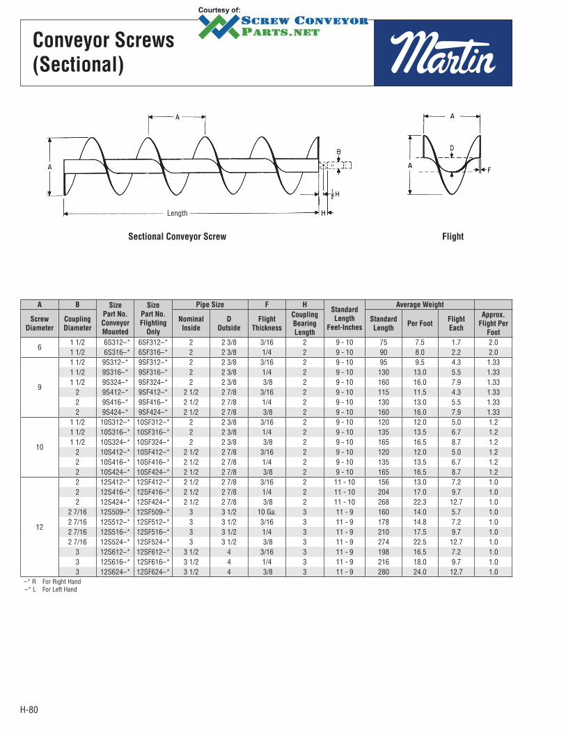
H-80
Conveyor Screws
(Sectional)
Length
Sectional Conveyor Screw Flight
A B Size
Part No.
Conveyor
Mounted
Size
Part No.
Flighting
Only
Pipe Size F HStandard
Length
Feet-Inches
Average Weight
Screw
Diameter
Coupling
Diameter
Nominal
Inside
D
Outside
Flight
Thickness
Coupling
Bearing
Length
Standard
LengthPer Foot
Flight
Each
Approx.
Flight Per
Foot
61 1/2 6S312–* 6SF312–* 2 2 3/8 3/16 2 9 - 10 75 7.5 1.7 2.01 1/2 6S316–* 6SF316–* 2 2 3/8 1/4 2 9 - 10 90 8.0 2.2 2.0
9
1 1/2 9S312–* 9SF312–* 2 2 3/8 3/16 2 9 - 10 95 9.5 4.3 1.331 1/2 9S316–* 9SF316–* 2 2 3/8 1/4 2 9 - 10 130 13.0 5.5 1.331 1/2 9S324–* 9SF324–* 2 2 3/8 3/8 2 9 - 10 160 16.0 7.9 1.33
2 9S412–* 9SF412–* 2 1/2 2 7/8 3/16 2 9 - 10 115 11.5 4.3 1.332 9S416–* 9SF416–* 2 1/2 2 7/8 1/4 2 9 - 10 130 13.0 5.5 1.332 9S424–* 9SF424–* 2 1/2 2 7/8 3/8 2 9 - 10 160 16.0 7.9 1.33
10
1 1/2 10S312–* 10SF312–* 2 2 3/8 3/16 2 9 - 10 120 12.0 5.0 1.21 1/2 10S316–* 10SF316–* 2 2 3/8 1/4 2 9 - 10 135 13.5 6.7 1.21 1/2 10S324–* 10SF324–* 2 2 3/8 3/8 2 9 - 10 165 16.5 8.7 1.2
2 10S412–* 10SF412–* 2 1/2 2 7/8 3/16 2 9 - 10 120 12.0 5.0 1.22 10S416–* 10SF416–* 2 1/2 2 7/8 1/4 2 9 - 10 135 13.5 6.7 1.22 10S424–* 10SF424–* 2 1/2 2 7/8 3/8 2 9 - 10 165 16.5 8.7 1.2
12
2 12S412–* 12SF412–* 2 1/2 2 7/8 3/16 2 11 - 10 156 13.0 7.2 1.02 12S416–* 12SF416–* 2 1/2 2 7/8 1/4 2 11 - 10 204 17.0 9.7 1.02 12S424–* 12SF424–* 2 1/2 2 7/8 3/8 2 11 - 10 268 22.3 12.7 1.0
2 7/16 12S509–* 12SF509–* 3 3 1/2 10 Ga. 3 11 - 9 160 14.0 5.7 1.02 7/16 12S512–* 12SF512–* 3 3 1/2 3/16 3 11 - 9 178 14.8 7.2 1.02 7/16 12S516–* 12SF516–* 3 3 1/2 1/4 3 11 - 9 210 17.5 9.7 1.02 7/16 12S524–* 12SF524–* 3 3 1/2 3/8 3 11 - 9 274 22.5 12.7 1.0
3 12S612–* 12SF612–* 3 1/2 4 3/16 3 11 - 9 198 16.5 7.2 1.03 12S616–* 12SF616–* 3 1/2 4 1/4 3 11 - 9 216 18.0 9.7 1.03 12S624–* 12SF624–* 3 1/2 4 3/8 3 11 - 9 280 24.0 12.7 1.0
–* R For Right Hand –* L For Left Hand
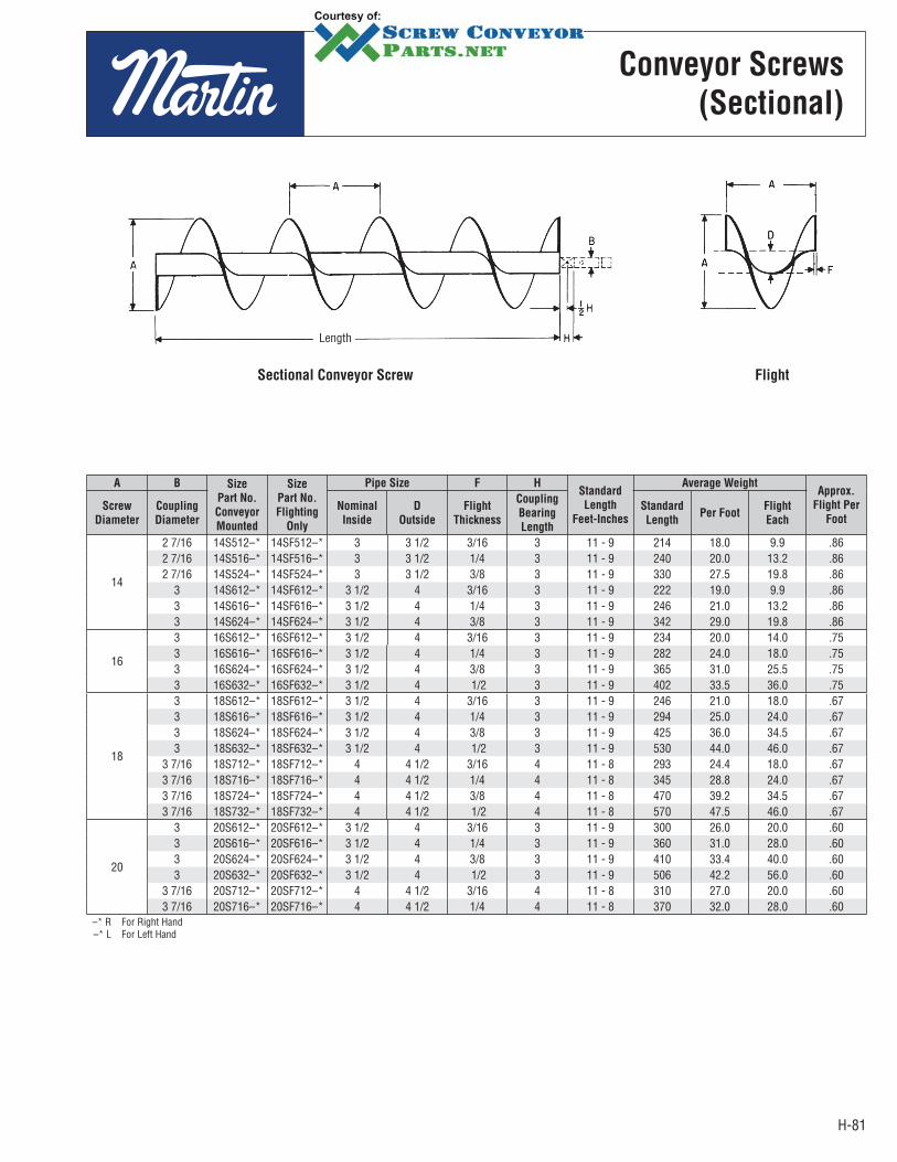
H-81
Conveyor Screws
(Sectional)
Length
Sectional Conveyor Screw Flight
A B Size
Part No.
Conveyor
Mounted
Size
Part No.
Flighting
Only
Pipe Size F HStandard
Length
Feet-Inches
Average WeightApprox.
Flight Per
Foot
Screw
Diameter
Coupling
Diameter
Nominal
Inside
D
Outside
Flight
Thickness
Coupling
Bearing
Length
Standard
LengthPer Foot
Flight
Each
14
2 7/16 14S512–* 14SF512–* 3 3 1/2 3/16 3 11 - 9 214 18.0 9.9 .862 7/16 14S516–* 14SF516–* 3 3 1/2 1/4 3 11 - 9 240 20.0 13.2 .862 7/16 14S524–* 14SF524–* 3 3 1/2 3/8 3 11 - 9 330 27.5 19.8 .86
3 14S612–* 14SF612–* 3 1/2 4 3/16 3 11 - 9 222 19.0 9.9 .863 14S616–* 14SF616–* 3 1/2 4 1/4 3 11 - 9 246 21.0 13.2 .863 14S624–* 14SF624–* 3 1/2 4 3/8 3 11 - 9 342 29.0 19.8 .86
16
3 16S612–* 16SF612–* 3 1/2 4 3/16 3 11 - 9 234 20.0 14.0 .753 16S616–* 16SF616–* 3 1/2 4 1/4 3 11 - 9 282 24.0 18.0 .753 16S624–* 16SF624–* 3 1/2 4 3/8 3 11 - 9 365 31.0 25.5 .753 16S632–* 16SF632–* 3 1/2 4 1/2 3 11 - 9 402 33.5 36.0 .75
18
3 18S612–* 18SF612–* 3 1/2 4 3/16 3 11 - 9 246 21.0 18.0 .673 18S616–* 18SF616–* 3 1/2 4 1/4 3 11 - 9 294 25.0 24.0 .673 18S624–* 18SF624–* 3 1/2 4 3/8 3 11 - 9 425 36.0 34.5 .673 18S632–* 18SF632–* 3 1/2 4 1/2 3 11 - 9 530 44.0 46.0 .67
3 7/16 18S712–* 18SF712–* 4 4 1/2 3/16 4 11 - 8 293 24.4 18.0 .673 7/16 18S716–* 18SF716–* 4 4 1/2 1/4 4 11 - 8 345 28.8 24.0 .673 7/16 18S724–* 18SF724–* 4 4 1/2 3/8 4 11 - 8 470 39.2 34.5 .673 7/16 18S732–* 18SF732–* 4 4 1/2 1/2 4 11 - 8 570 47.5 46.0 .67
20
3 20S612–* 20SF612–* 3 1/2 4 3/16 3 11 - 9 300 26.0 20.0 .603 20S616–* 20SF616–* 3 1/2 4 1/4 3 11 - 9 360 31.0 28.0 .603 20S624–* 20SF624–* 3 1/2 4 3/8 3 11 - 9 410 33.4 40.0 .603 20S632–* 20SF632–* 3 1/2 4 1/2 3 11 - 9 506 42.2 56.0 .60
3 7/16 20S712–* 20SF712–* 4 4 1/2 3/16 4 11 - 8 310 27.0 20.0 .603 7/16 20S716–* 20SF716–* 4 4 1/2 1/4 4 11 - 8 370 32.0 28.0 .60
–* R For Right Hand –* L For Left Hand
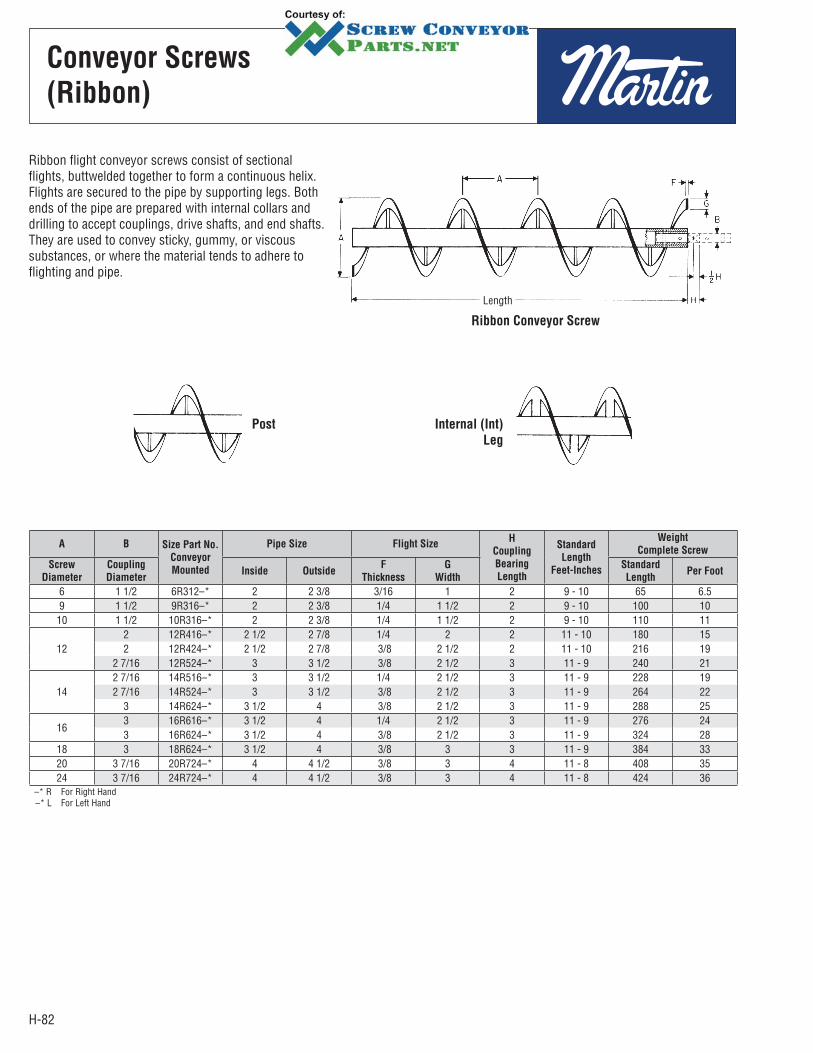
H-82
Conveyor Screws
(Ribbon)
Length
Ribbon Conveyor Screw
A B Size Part No.
Conveyor
Mounted
Pipe Size Flight SizeH
Coupling
Bearing
Length
Standard
Length
Feet-Inches
Weight
Complete Screw
Screw
Diameter
Coupling
DiameterInside Outside
F
Thickness
G
Width
Standard
LengthPer Foot
6 1 1/2 6R312–* 2 2 3/8 3/16 1 2 9 - 10 65 6.5 9 1 1/2 9R316–* 2 2 3/8 1/4 1 1/2 2 9 - 10 100 10 10 1 1/2 10R316–* 2 2 3/8 1/4 1 1/2 2 9 - 10 110 11
122 12R416–* 2 1/2 2 7/8 1/4 2 2 11 - 10 180 15 2 12R424–* 2 1/2 2 7/8 3/8 2 1/2 2 11 - 10 216 19
2 7/16 12R524–* 3 3 1/2 3/8 2 1/2 3 11 - 9 240 21
142 7/16 14R516–* 3 3 1/2 1/4 2 1/2 3 11 - 9 228 19 2 7/16 14R524–* 3 3 1/2 3/8 2 1/2 3 11 - 9 264 22
3 14R624–* 3 1/2 4 3/8 2 1/2 3 11 - 9 288 25
163 16R616–* 3 1/2 4 1/4 2 1/2 3 11 - 9 276 24 3 16R624–* 3 1/2 4 3/8 2 1/2 3 11 - 9 324 28
18 3 18R624–* 3 1/2 4 3/8 3 3 11 - 9 384 33 20 3 7/16 20R724–* 4 4 1/2 3/8 3 4 11 - 8 408 35 24 3 7/16 24R724–* 4 4 1/2 3/8 3 4 11 - 8 424 36
–* R For Right Hand –* L For Left Hand
Ribbon flight conveyor screws consist of sectional flights, buttwelded together to form a continuous helix. Flights are secured to the pipe by supporting legs. Both ends of the pipe are prepared with internal collars and drilling to accept couplings, drive shafts, and end shafts. They are used to convey sticky, gummy, or viscous substances, or where the material tends to adhere to flighting and pipe.
Post Internal (Int)
Leg
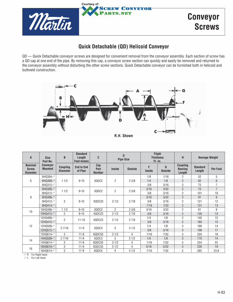
H-83
Quick Detachable (QD) Helicoid Conveyor
QD — Quick Detachable conveyor screws are designed for convenient removal from the conveyor assembly. Each section of screw has a QD cap at one end of the pipe. By removing this cap, a conveyor screw section can quickly and easily be removed and returned to the conveyor assembly without disturbing the other screw sections. Quick Detachable conveyor can be furnished both in helicoid and buttweld construction.
Conveyor
Screws
R.H. Shown
A Size
Part No.
Conveyor
Mounted
B
Standard
Length
Feet-Inches
CD
Pipe Size
Flight
Thickness
Ft.-In.
H Average Weight
Nominal
Screw
Diameter
Coupling
Diameter
End to End
of Pipe
Cap
Part
Number
Inside OutsideF
Inside
G
Outside
Coupling
Bearing
Length
Standard
LengthPer Foot
6 6HQ304–*
1 1/2 9-10 3QDC2 2 2 3/81/8 1/16 2 52 5
6HQ308–* 1/4 1/8 2 62 6 6HQ312–* 3/8 3/16 2 72 7
9
9HQ306–*1 1/2 9-10 3QDC2 2 2 3/8
3/16 3/32 2 70 7 9HQ312–* 3/8 3/16 2 101 10 9HQ406–*
2 9-10 4QDC25 2 1/2 2 7/83/16 3/32 2 91 9
9HQ412–* 3/8 3/16 2 121 12 9HQ414–* 7/16 7/32 2 131 13
1010HQ306–* 1 1/2 9-10 3QDC2 2 2 3/8 3/16 3/32 2 81 810HQ412–* 2 9-10 4QDC25 2 1/2 2 7/8 3/8 3/16 2 130 13
12
12HQ408–*2 11-10 4QDC25 2 1/2 2 7/8
1/4 1/8 2 140 1212HQ412–* 3/8 3/16 2 180 1512HQ508–*
2 7/16 11-9 5QDC3 3 3 1/21/4 1/8 3 168 14
12HQ512–* 3/8 3/16 3 198 1712HQ614–* 3 11-9 6QDC35 3 1/2 4 7/16 7/32 3 220 18
1414HQ508–* 2 7/16 11-9 5QDC3 3 3 1/2 1/4 1/8 3 170 1414HQ614–* 3 11-9 6QDC35 3 1/2 4 7/16 7/32 3 254 22
1616HQ610–* 3 11-9 6QDC35 3 1/2 4 5/16 5/32 3 228 1916HQ614–* 3 11-9 6QDC4 4 4 1/2 7/16 7/32 3 285 23.8
–* R For Right Hand –* L For Left Hand
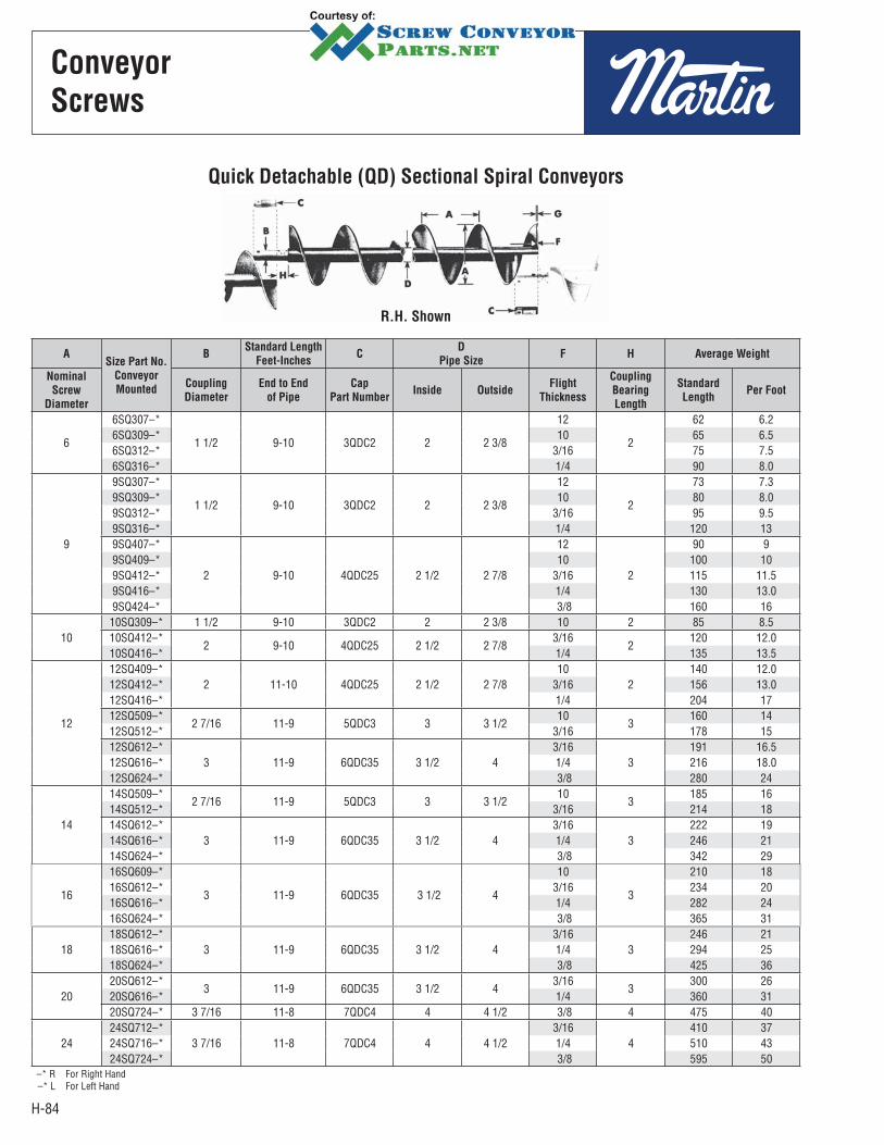
H-84
Quick Detachable (QD) Sectional Spiral Conveyors
R.H. Shown
ASize Part No.
Conveyor
Mounted
BStandard Length
Feet-InchesC
D
Pipe SizeF H Average Weight
Nominal
Screw
Diameter
Coupling
Diameter
End to End
of Pipe
Cap
Part NumberInside Outside
Flight
Thickness
Coupling
Bearing
Length
Standard
LengthPer Foot
6
6SQ307–*
1 1/2 9-10 3QDC2 2 2 3/8
12
2
62 6.2 6SQ309–* 10 65 6.5 6SQ312–* 3/16 75 7.5 6SQ316–* 1/4 90 8.0
9
9SQ307–*
1 1/2 9-10 3QDC2 2 2 3/8
12
2
73 7.3 9SQ309–* 10 80 8.0 9SQ312–* 3/16 95 9.5 9SQ316–* 1/4 120 13 9SQ407–*
2 9-10 4QDC25 2 1/2 2 7/8
12
2
90 9 9SQ409–* 10 100 10 9SQ412–* 3/16 115 11.5 9SQ416–* 1/4 130 13.0 9SQ424–* 3/8 160 16
1010SQ309–* 1 1/2 9-10 3QDC2 2 2 3/8 10 2 85 8.5 10SQ412–*
2 9-10 4QDC25 2 1/2 2 7/83/16
2120 12.0
10SQ416–* 1/4 135 13.5
12
12SQ409–*2 11-10 4QDC25 2 1/2 2 7/8
102
140 12.0 12SQ412–* 3/16 156 13.0 12SQ416–* 1/4 204 17 12SQ509–*
2 7/16 11-9 5QDC3 3 3 1/210
3160 14
12SQ512–* 3/16 178 15 12SQ612–*
3 11-9 6QDC35 3 1/2 43/16
3191 16.5
12SQ616–* 1/4 216 18.0 12SQ624–* 3/8 280 24
14
14SQ509–*2 7/16 11-9 5QDC3 3 3 1/2
103
185 16 14SQ512–* 3/16 214 18 14SQ612–*
3 11-9 6QDC35 3 1/2 43/16
3222 19
14SQ616–* 1/4 246 21 14SQ624–* 3/8 342 29
16
16SQ609–*
3 11-9 6QDC35 3 1/2 4
10
3
210 18 16SQ612–* 3/16 234 20 16SQ616–* 1/4 282 24 16SQ624–* 3/8 365 31
1818SQ612–*
3 11-9 6QDC35 3 1/2 43/16
3246 21
18SQ616–* 1/4 294 25 18SQ624–* 3/8 425 36
2020SQ612–*
3 11-9 6QDC35 3 1/2 43/16
3300 26
20SQ616–* 1/4 360 31 20SQ724–* 3 7/16 11-8 7QDC4 4 4 1/2 3/8 4 475 40
2424SQ712–*
3 7/16 11-8 7QDC4 4 4 1/23/16
4410 37
24SQ716–* 1/4 510 43 24SQ724–* 3/8 595 50
–* R For Right Hand –* L For Left Hand
Conveyor
Screws
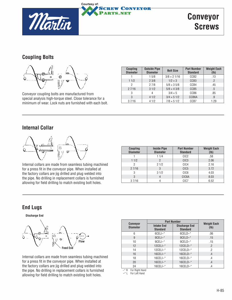
H-85
Conveyor
Screws
Coupling Bolts
Conveyor coupling bolts are manufactured from special analysis high-torque steel. Close tolerance for a minimum of wear. Lock nuts are furnished with each bolt.
Coupling
Diameter
Outside Pipe
DiameterBolt Size
Part Number
Standard
Weight Each
(lb)
1 1 5/8 3/8 × 2 1/16 CCB2 .131 1/2 2 3/8 1/2 × 3 CCB3 .2
2 2 7/8 5/8 × 3 5/8 CCB4 .452 7/16 3 1/2 5/8 × 4 3/8 CCB5 .5
3 4 3/4 × 5 CCB6 .853 4 1/2 3/4 × 5 1/2 CCB6A .9
3 7/16 4 1/2 7/8 × 5 1/2 CCB7 1.29
Internal Collar
Internal collars are made from seamless tubing machined for a press fit in the conveyor pipe. When installed at the factory collars are jig drilled and plug welded into the pipe. No drilling in replacement collars is furnished allowing for field drilling to match existing bolt holes.
Coupling
Diameter
Inside Pipe
Diameter
Part Number
Standard
Weight Each
(lb)
1 1 1/4 CIC2 .581 1/2 2 CIC3 2.06
2 2 1/2 CIC4 2.162 7/16 3 CIC5 3.72
3 3 1/2 CIC6 4.033 4 CIC6A 8.03
3 7/16 4 CIC7 6.52
Conveyor
Diameter
Part NumberWeight Each
(lb)Intake End
Standard
Discharge End
Standard
6 6CELI–* 6CELD–* .069 9CELI–* 9CELD–* .1510 9CELI–* 9CELD–* .1512 12CELI–* 12CELD–* .214 12CELI–* 12CELD–* .216 16CELI–* 16CELD–* .418 16CELI–* 16CELD–* .420 16CELI–* 16CELD–* .424 16CELI–* 16CELD–* .4
–* R For Right Hand –* L For Left Hand
End Lugs
Internal collars are made from seamless tubing machined for a press fit in the conveyor pipe. When installed at the factory collars are jig drilled and plug welded into the pipe. No drilling in replacement collars is furnished allowing for field drilling to match existing bolt holes.
Flow
Feed End
Discharge End
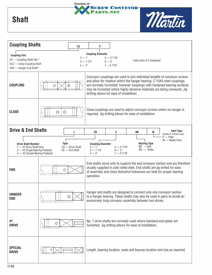
H-86
Shaft
Coupling Shafts
Coupling Part
CC — Coupling Shaft Std.*CCC — Close Coupling ShaftCHE — Hanger End Shaft*
* Add suffix H if Hardened
Coupling Diameter
2 — 1" 5 — 2 7/16"3 — 1 1/2" 6 — 3"4 — 2" 7 —3 7/16"
CC 5
COUPLING
Conveyor couplings are used to join individual lengths of conveyor screws and allow for rotation within the hanger bearing. C-1045 steel couplings are normally furnished; however couplings with hardened bearing surfaces may be furnished where highly abrasive materials are being conveyed. Jig drilling allows for ease of installation.
CLOSEClose couplings are used to adjoin conveyor screws where no hanger is required. Jig drilling allows for ease of installation.
Drive & End Shafts
Drive Shaft Number
1 — #1 Drive Shaft Only2 — #2 Single Bearing Pedestal3 — #3 Double Bearing Pedestal
Type
CD — Drive ShaftCE — End Shaft
Seal Type
(Delete if without seal)P — PlateW — Waste Pack
Coupling Diameter
2 — 1" 5 — 2 7/16"3 — 1 1/2" 6 — 3"4 — 2" 7 — 3 7/16"
Bearing Type
BB — BallRB — Roller
1 CD 5 BB W
END
End shafts serve only to support the end conveyor section and are therefore usually supplied in cold rolled steel. End shafts are jig drilled for ease of assembly and close diametral tolerances are held for proper bearing operation.
HANGER
END
Hanger end shafts are designed to connect only one conveyor section to a hanger bearing. These shafts may also be used in pairs to divide an excessively long conveyor assembly between two drives.
#1
DRIVE
No. 1 drive shafts are normally used where standard end plates are furnished. Jig drilling allows for ease of installation.
SPECIAL
DRIVELength, bearing location, seals and keyway location and size as required.

H-87
No. 1
Drive Shaft
No. 1 drive shafts are normally used where standard end plates are furnished. Jig drilling allows for ease of instal lation.
No. 1 Drive Shaft Used Without Seal*Bronze Bearing Ball Bearing
Shaft
Diameter
Part
NumberC G H Weight
Shaft
Diameter
Part
NumberC G H Weight
1 1CD2B 9 1/2 31/2 3 2.0 1 1CD2BB 9 3 3 1.8 1 1/2 1CD3B 12 3/4 43/4 3 1/4 6.3 1 1/2 1CD3BB 11 1/2 31/2 3 1/4 5.6
2 1CD4B 15 53/4 4 1/2 13.3 2 1CD4BB 13 1/8 37/8 4 1/2 11.5 2 7/16 1CD5B 17 3/8 7 5 1/2 21.0 2 7/16 1CD5BB 15 1/8 43/4 5 1/2 18.0
3 1CD6B 19 1/8 81/8 6 37.0 3 1CD6BB 16 5/8 55/8 6 32.0 3 7/16 1CD7B 23 9 7 1/4 60.4 3 7/16 1CD7BB 20 5/8 65/8 7 1/4 52.5
*Consult Factory
No. 1 Drive Shaft Used With Plate or Product Drop Out Seals*Bronze Bearing Ball Bearing
Shaft
Diameter
Part
NumberC G H Weight
Shaft
Diameter
Part
NumberC G H Weight
1 1CD2B-P 10 4 3 2.1 1 1CD2BB-P 9 1/2 3 1/2 3 2.01 1/2 1CD3B-P 13 1/4 5 1/4 3 1/4 6.6 1 1/2 1CD3BB-P 12 3/8 4 3/8 3 1/4 6.2
2 1CD4B-P 15 1/4 6 1/4 4 1/2 14.1 2 1CD4BB-P 14 4 3/4 4 1/2 12.52 7/16 1CD5B-P 18 3/8 8 5 1/2 24.3 2 7/16 1CD5BB-P 15 7/8 5 1/2 5 1/2 21.0
3 1CD6B-P 19 5/8 8 5/8 6 38.0 3 1CD6BB-P 17 1/2 6 1/2 6 35.03 7/16 1CD7B-P 24 1/8 10 1/8 7 1/4 61.0 3 7/16 1CD7BB-P 21 1/2 7 1/2 7 1/4 56.5
*Consult Factory
No. 1 Drive Shaft Used With Waste Pack Seal*Bronze Bearing Ball Bearing
Shaft
Diameter
Part
NumberC G H Weight
Shaft
Diameter
Part
NumberC G H Weight
1 1CD2B-W 11 4 1/4 3 2.2 1 1CD2BB-W 10 1/2 3 3/4 3.0 2.01 1/2 1CD3B-W 14 1/2 6 1/2 3 1/4 7.2 1 1/2 1CD3BB-W 13 1/4 5 1/4 3.3 6.4
2 1CD4B-W 16 3/4 7 1/4 4 1/2 14.9 2 1CD4BB-W 14 7/8 5 5/8 4.5 13.02 7/16 1CD5B-W 19 1/8 8 3/4 5 1/2 23.3 2 7/16 1CD5BB-W 16 7/8 6 1/2 5.5 20.5
3 1CD6B-W 20 7/8 9 7/8 6 40.5 3 1CD6BB-W 18 3/8 7 3/8 6.0 35.53 7/16 1CD7B-W 25 7/8 11 7/8 7 1/4 66.3 3 7/16 1CD7BB-W 22 7/8 8 7/8 7.3 58.4
Shaft length allows for 1/2 hanger bearing length as clearance between end plate and screw*Consult Factory
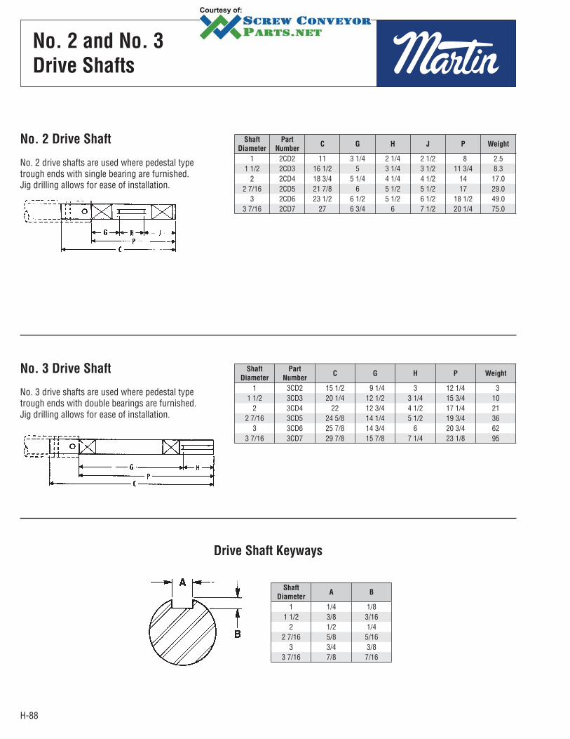
H-88
No. 2 and No. 3
Drive Shafts
No. 2 Drive Shaft
No. 2 drive shafts are used where pedestal type trough ends with single bearing are furnished. Jig drilling allows for ease of installation.
Shaft
Diameter
Part
NumberC G H J P Weight
1 2CD2 11 3 1/4 2 1/4 2 1/2 8 2.5 1 1/2 2CD3 16 1/2 5 3 1/4 3 1/2 11 3/4 8.3
2 2CD4 18 3/4 5 1/4 4 1/4 4 1/2 14 17.0 2 7/16 2CD5 21 7/8 6 5 1/2 5 1/2 17 29.0
3 2CD6 23 1/2 6 1/2 5 1/2 6 1/2 18 1/2 49.0 3 7/16 2CD7 27 6 3/4 6 7 1/2 20 1/4 75.0
No. 3 Drive Shaft
No. 3 drive shafts are used where pedestal type trough ends with double bearings are furnished. Jig drilling allows for ease of installation.
Shaft
Diameter
Part
NumberC G H P Weight
1 3CD2 15 1/2 9 1/4 3 12 1/4 31 1/2 3CD3 20 1/4 12 1/2 3 1/4 15 3/4 10
2 3CD4 22 12 3/4 4 1/2 17 1/4 212 7/16 3CD5 24 5/8 14 1/4 5 1/2 19 3/4 36
3 3CD6 25 7/8 14 3/4 6 20 3/4 623 7/16 3CD7 29 7/8 15 7/8 7 1/4 23 1/8 95
Drive Shaft Keyways
Shaft
DiameterA B
1 1/4 1/81 1/2 3/8 3/16
2 1/2 1/42 7/16 5/8 5/16
3 3/4 3/83 7/16 7/8 7/16
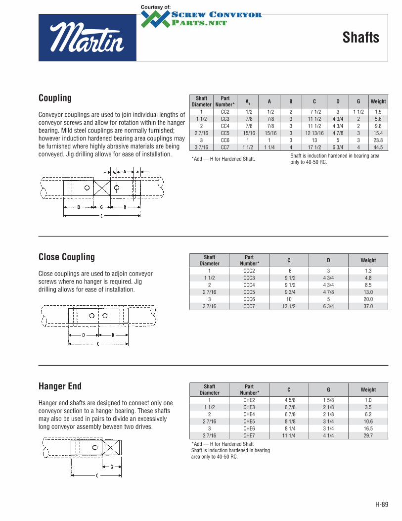
H-89
Coupling
Conveyor couplings are used to join individual lengths of conveyor screws and allow for rotation within the hanger bearing. Mild steel couplings are normally furnished; however induction hardened bearing area couplings may be furnished where highly abrasive materials are being conveyed. Jig drilling allows for ease of installation.
Shaft
Diameter
Part
Number*A
1A B C D G Weight
1 CC2 1/2 1/2 2 7 1/2 3 1 1/2 1.51 1/2 CC3 7/8 7/8 3 11 1/2 4 3/4 2 5.6
2 CC4 7/8 7/8 3 11 1/2 4 3/4 2 9.82 7/16 CC5 15/16 15/16 3 12 13/16 4 7/8 3 15.4
3 CC6 1 1 3 13 5 3 23.83 7/16 CC7 1 1/2 1 1/4 4 17 1/2 6 3/4 4 44.5
*Add — H for Hardened Shaft. Shaft is induction hardened in bearing area only to 40-50 RC.
Close Coupling
Close couplings are used to adjoin conveyor screws where no hanger is required. Jig drilling allows for ease of installation.
Shaft
Diameter
Part
Number*C D Weight
1 CCC2 6 3 1.31 1/2 CCC3 9 1/2 4 3/4 4.8
2 CCC4 9 1/2 4 3/4 8.52 7/16 CCC5 9 3/4 4 7/8 13.0
3 CCC6 10 5 20.0 3 7/16 CCC7 13 1/2 6 3/4 37.0
Hanger End
Hanger end shafts are designed to connect only one conveyor section to a hanger bearing. These shafts may also be used in pairs to divide an excessively long conveyor assembly beween two drives.
Shaft
Diameter
Part
Number*C G Weight
1 CHE2 4 5/8 1 5/8 1.01 1/2 CHE3 6 7/8 2 1/8 3.5
2 CHE4 6 7/8 2 1/8 6.22 7/16 CHE5 8 1/8 3 1/4 10.6
3 CHE6 8 1/4 3 1/4 16.53 7/16 CHE7 11 1/4 4 1/4 29.7
*Add — H for Hardened ShaftShaft is induction hardened in bearingarea only to 40-50 RC.
Shafts
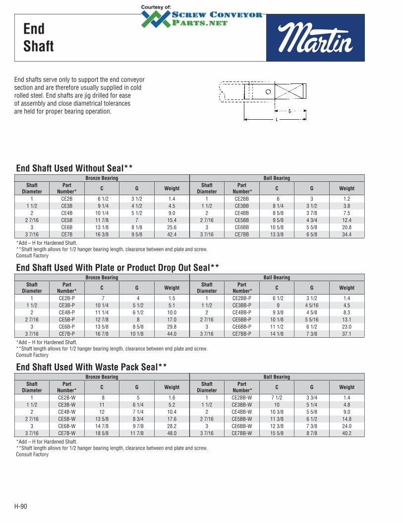
H-90
End
Shaft
End shafts serve only to support the end conveyor section and are therefore usually supplied in cold rolled steel. End shafts are jig drilled for ease of assembly and close diametrical tolerances are held for proper bearing operation.
End Shaft Used Without Seal**Bronze Bearing Ball Bearing
Shaft
Diameter
Part
Number*C G Weight
Shaft
Diameter
Part
Number*C G Weight
1 CE2B 6 1/2 3 1/2 1.4 1 CE2BB 6 3 1.21 1/2 CE3B 9 1/4 4 1/2 4.5 1 1/2 CE3BB 8 1/4 3 1/2 3.8
2 CE4B 10 1/4 5 1/2 9.0 2 CE4BB 8 5/8 3 7/8 7.52 7/16 CE5B 11 7/8 7 15.4 2 7/16 CE5BB 9 5/8 4 3/4 12.4
3 CE6B 13 1/8 8 1/8 25.6 3 CE6BB 10 5/8 5 5/8 20.83 7/16 CE7B 16 3/8 9 5/8 42.4 3 7/16 CE7BB 13 3/8 6 5/8 34.4
*Add – H for Hardened Shaft.**Shaft length allows for 1/2 hanger bearing length, clearance between end plate and screw.Consult Factory
End Shaft Used With Plate or Product Drop Out Seal**Bronze Bearing Ball Bearing
Shaft
Diameter
Part
Number*C G Weight
Shaft
Diameter
Part
Number*C G Weight
1 CE2B-P 7 4 1.5 1 CE2BB-P 6 1/2 3 1/2 1.41 1/2 CE3B-P 10 1/4 5 1/2 5.1 1 1/2 CE3BB-P 9 4 5/16 4.5
2 CE4B-P 11 1/4 6 1/2 10.0 2 CE4BB-P 9 3/8 4 5/8 8.32 7/16 CE5B-P 12 7/8 8 17.0 2 7/16 CE5BB-P 10 1/8 5 5/16 13.1
3 CE6B-P 13 5/8 8 5/8 29.8 3 CE6BB-P 11 1/2 6 1/2 23.03 7/16 CE7B-P 16 7/8 10 1/8 44.0 3 7/16 CE7BB-P 14 1/8 7 3/8 37.1
*Add – H for Hardened Shaft.**Shaft length allows for 1/2 hanger bearing length, clearance between end plate and screw.Consult Factory
End Shaft Used With Waste Pack Seal**Bronze Bearing Ball Bearing
Shaft
Diameter
Part
Number*C G Weight
Shaft
Diameter
Part
Number*C G Weight
1 CE2B-W 8 5 1.6 1 CE2BB-W 7 1/2 3 3/4 1.41 1/2 CE3B-W 11 6 1/4 5.2 1 1/2 CE3BB-W 10 5 1/4 4.8
2 CE4B-W 12 7 1/4 10.4 2 CE4BB-W 10 3/8 5 5/8 9.02 7/16 CE5B-W 13 5/8 8 3/4 17.6 2 7/16 CE5BB-W 11 3/8 6 1/2 14.8
3 CE6B-W 14 7/8 9 7/8 28.2 3 CE6BB-W 12 3/8 7 3/8 24.03 7/16 CE7B-W 18 5/8 11 7/8 48.0 3 7/16 CE7BB-W 15 5/8 8 7/8 40.2
*Add – H for Hardened Shaft.**Shaft length allows for 1/2 hanger bearing length, clearance between end plate and screw.Consult Factory
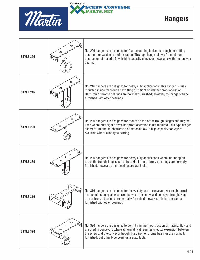
H-91
STYLE 226
No. 226 hangers are designed for flush mounting inside the trough permitting dust-tight or weather-proof operation. This type hanger allows for minimum obstruction of material flow in high capacity conveyors. Available with friction type bearing.
STYLE 216
No. 216 hangers are designed for heavy duty applications. This hanger is flush mounted inside the trough permitting dust tight or weather proof operation. Hard iron or bronze bearings are normally furnished; however, the hanger can be furnished with other bearings.
STYLE 220
No. 220 hangers are designed for mount on top of the trough flanges and may be used where dust-tight or weather proof operation is not required. This type hanger allows for minimum obstruction of material flow in high capacity conveyors. Available with friction type bearing.
STYLE 230
No. 230 hangers are designed for heavy duty applications where mounting on top of the trough flanges is required. Hard iron or bronze bearings are normally furnished; however, other bearings are available.
STYLE 316
No. 316 hangers are designed for heavy duty use in conveyors where abnormal heat requires unequal expansion between the screw and conveyor trough. Hard iron or bronze bearings are normally furnished; however, this hanger can be furnished with other bearings.
STYLE 326
No. 326 hangers are designed to permit minimum obstruction of material flow and are used in conveyors where abnormal heat requires unequal expansion between the screw and the conveyor trough. Hard iron or bronze bearings are normally furnished, but other type bearings are available.
Hangers
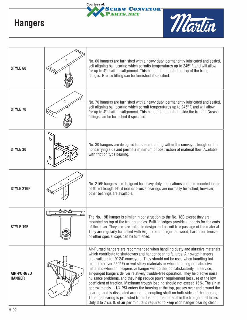
H-92
STYLE 60
No. 60 hangers are furnished with a heavy duty, permanently lubricated and sealed, self aligning ball bearing which permits temperatures up to 245º F. and will allow for up to 4º shaft misalignment. This hanger is mounted on top of the trough flanges. Grease fitting can be furnished if specified.
STYLE 70
No. 70 hangers are furnished with a heavy duty, permanently lubricated and sealed, self aligning ball bearing which permit temperatures up to 245º F. and will allow for up to 4º shaft misalignment. This hanger is mounted inside the trough. Grease fittings can be furnished if specified.
STYLE 30
No. 30 hangers are designed for side mounting within the conveyor trough on the noncarrying side and permit a minimum of obstruction of material flow. Available with friction type bearing.
STYLE 216F
No. 216F hangers are designed for heavy duty applications and are mounted inside of flared trough. Hard iron or bronze bearings are normally furnished; however, other bearings are available.
STYLE 19B
The No. 19B hanger is similar in construction to the No. 18B except they are mounted on top of the trough angles. Built-in ledges provide supports for the ends of the cover. They are streamline in design and permit free passage of the material. They are regularly furnished with Arguto oil impregnated wood, hard iron, bronze, or other special caps can be furnished.
AIR-PURGED
HANGER
Air-Purged hangers are recommended when handling dusty and abrasive materials which contribute to shutdowns and hanger bearing failures. Air-swept hangers are available for 9"-24" conveyors. They should not be used when handling hot materials (over 250º F) or wet sticky materials or when handling non abrasive materials when an inexpensive hanger will do the job satisfactorily. In service, air-purged hangers deliver relatively trouble-free operation. They help solve noise nuisance problems, and they help reduce power requirement because of the low coefficient of fraction. Maximum trough loading should not exceed 15%. The air, at approximately 1-1/4 PSI enters the housing at the top, passes over and around the bearing, and is dissipated around the coupling shaft on both sides of the housing. Thus the bearing is protected from dust and the material in the trough at all times. Only 3 to 7 cu. ft. of air per minute is required to keep each hanger bearing clean.
Hangers
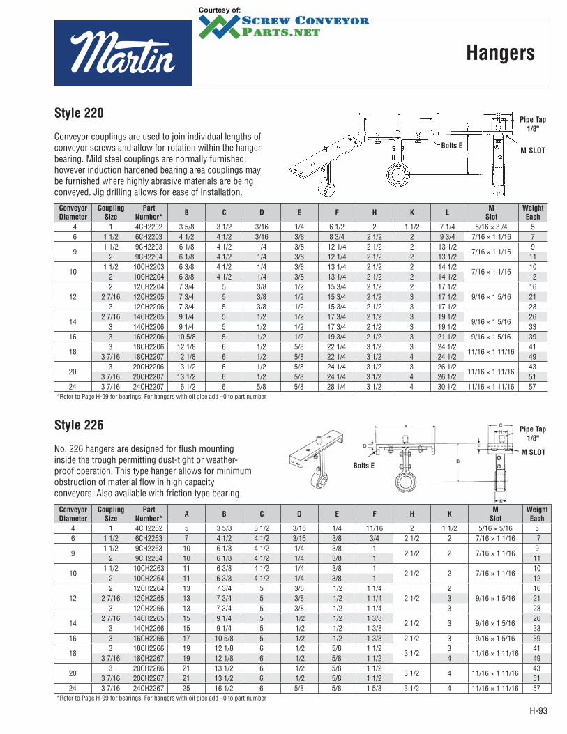
H-93
Hangers
Conveyor
Diameter
Coupling
Size
Part
Number*B C D E F H K L
M
Slot
Weight
Each
4 1 4CH2202 3 5/8 3 1/2 3/16 1/4 6 1/2 2 1 1/2 7 1/4 5/16 × 3 /4 5 6 1 1/2 6CH2203 4 1/2 4 1/2 3/16 3/8 8 3/4 2 1/2 2 9 3/4 7/16 × 1 1/16 7
91 1/2 9CH2203 6 1/8 4 1/2 1/4 3/8 12 1/4 2 1/2 2 13 1/2
7/16 × 1 1/169
2 9CH2204 6 1/8 4 1/2 1/4 3/8 12 1/4 2 1/2 2 13 1/2 11
101 1/2 10CH2203 6 3/8 4 1/2 1/4 3/8 13 1/4 2 1/2 2 14 1/2
7/16 × 1 1/1610
2 10CH2204 6 3/8 4 1/2 1/4 3/8 13 1/4 2 1/2 2 14 1/2 12
122 12CH2204 7 3/4 5 3/8 1/2 15 3/4 2 1/2 2 17 1/2
9/16 × 1 5/1616
2 7/16 12CH2205 7 3/4 5 3/8 1/2 15 3/4 2 1/2 3 17 1/2 21 3 12CH2206 7 3/4 5 3/8 1/2 15 3/4 2 1/2 3 17 1/2 28
142 7/16 14CH2205 9 1/4 5 1/2 1/2 17 3/4 2 1/2 3 19 1/2
9/16 × 1 5/1626
3 14CH2206 9 1/4 5 1/2 1/2 17 3/4 2 1/2 3 19 1/2 33 16 3 16CH2206 10 5/8 5 1/2 1/2 19 3/4 2 1/2 3 21 1/2 9/16 × 1 5/16 39
183 18CH2206 12 1/8 6 1/2 5/8 22 1/4 3 1/2 3 24 1/2
11/16 × 1 11/1641
3 7/16 18CH2207 12 1/8 6 1/2 5/8 22 1/4 3 1/2 4 24 1/2 49
203 20CH2206 13 1/2 6 1/2 5/8 24 1/4 3 1/2 3 26 1/2
11/16 × 1 11/1643
3 7/16 20CH2207 13 1/2 6 1/2 5/8 24 1/4 3 1/2 4 26 1/2 51 24 3 7/16 24CH2207 16 1/2 6 5/8 5/8 28 1/4 3 1/2 4 30 1/2 11/16 × 1 11/16 57
*Refer to Page H-99 for bearings. For hangers with oil pipe add –0 to part number
Conveyor
Diameter
Coupling
Size
Part
Number*A B C D E F H K
M
Slot
Weight
Each
4 1 4CH2262 5 3 5/8 3 1/2 3/16 1/4 11/16 2 1 1/2 5/16 × 5/16 5 6 1 1/2 6CH2263 7 4 1/2 4 1/2 3/16 3/8 3/4 2 1/2 2 7/16 × 1 1/16 7
91 1/2 9CH2263 10 6 1/8 4 1/2 1/4 3/8 1
2 1/2 2 7/16 × 1 1/169
2 9CH2264 10 6 1/8 4 1/2 1/4 3/8 1 11
101 1/2 10CH2263 11 6 3/8 4 1/2 1/4 3/8 1
2 1/2 2 7/16 × 1 1/1610
2 10CH2264 11 6 3/8 4 1/2 1/4 3/8 1 12
122 12CH2264 13 7 3/4 5 3/8 1/2 1 1/4
2 1/22
9/16 × 1 5/1616
2 7/16 12CH2265 13 7 3/4 5 3/8 1/2 1 1/4 3 21 3 12CH2266 13 7 3/4 5 3/8 1/2 1 1/4 3 28
142 7/16 14CH2265 15 9 1/4 5 1/2 1/2 1 3/8
2 1/2 3 9/16 × 1 5/1626
3 14CH2266 15 9 1/4 5 1/2 1/2 1 3/8 33 16 3 16CH2266 17 10 5/8 5 1/2 1/2 1 3/8 2 1/2 3 9/16 × 1 5/16 39
183 18CH2266 19 12 1/8 6 1/2 5/8 1 1/2
3 1/23
11/16 × 1 11/1641
3 7/16 18CH2267 19 12 1/8 6 1/2 5/8 1 1/2 4 49
203 20CH2266 21 13 1/2 6 1/2 5/8 1 1/2
3 1/2 4 11/16 × 1 11/1643
3 7/16 20CH2267 21 13 1/2 6 1/2 5/8 1 1/2 51 24 3 7/16 24CH2267 25 16 1/2 6 5/8 5/8 1 5/8 3 1/2 4 11/16 × 1 11/16 57
*Refer to Page H-99 for bearings. For hangers with oil pipe add –0 to part number
Style 220
Conveyor couplings are used to join individual lengths of conveyor screws and allow for rotation within the hanger bearing. Mild steel couplings are normally furnished; however induction hardened bearing area couplings may be furnished where highly abrasive materials are being conveyed. Jig drilling allows for ease of installation.
Pipe Tap
1/8"
M SLOTBolts E
Style 226
No. 226 hangers are designed for flush mounting inside the trough permitting dust-tight or weather-proof operation. This type hanger allows for minimum obstruction of material flow in high capacity conveyors. Also available with friction type bearing.
Pipe Tap
1/8"
M SLOT
Bolts E
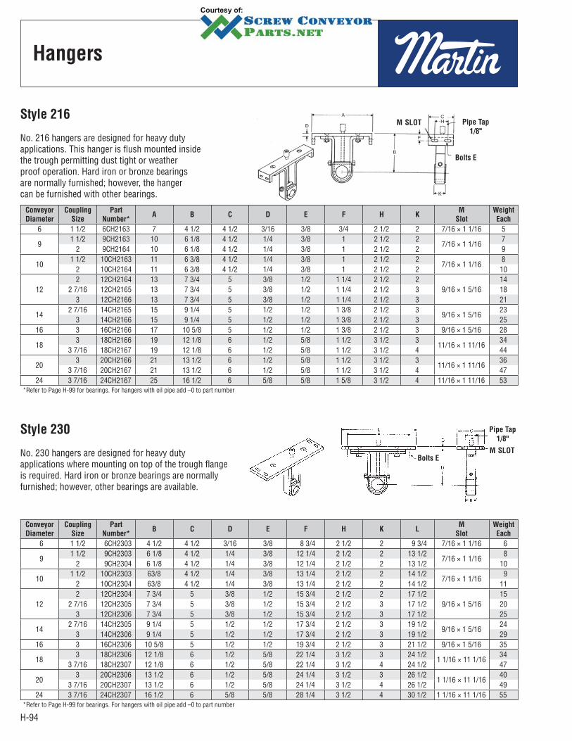
H-94
Hangers
Conveyor
Diameter
Coupling
Size
Part
Number*A B C D E F H K
M
Slot
Weight
Each
6 1 1/2 6CH2163 7 4 1/2 4 1/2 3/16 3/8 3/4 2 1/2 2 7/16 × 1 1/16 5
91 1/2 9CH2163 10 6 1/8 4 1/2 1/4 3/8 1 2 1/2 2
7/16 × 1 1/167
2 9CH2164 10 6 1/8 4 1/2 1/4 3/8 1 2 1/2 2 9
101 1/2 10CH2163 11 6 3/8 4 1/2 1/4 3/8 1 2 1/2 2
7/16 × 1 1/168
2 10CH2164 11 6 3/8 4 1/2 1/4 3/8 1 2 1/2 2 10
122 12CH2164 13 7 3/4 5 3/8 1/2 1 1/4 2 1/2 2
9/16 × 1 5/1614
2 7/16 12CH2165 13 7 3/4 5 3/8 1/2 1 1/4 2 1/2 3 18 3 12CH2166 13 7 3/4 5 3/8 1/2 1 1/4 2 1/2 3 21
142 7/16 14CH2165 15 9 1/4 5 1/2 1/2 1 3/8 2 1/2 3
9/16 × 1 5/1623
3 14CH2166 15 9 1/4 5 1/2 1/2 1 3/8 2 1/2 3 25 16 3 16CH2166 17 10 5/8 5 1/2 1/2 1 3/8 2 1/2 3 9/16 × 1 5/16 28
183 18CH2166 19 12 1/8 6 1/2 5/8 1 1/2 3 1/2 3
11/16 × 1 11/1634
3 7/16 18CH2167 19 12 1/8 6 1/2 5/8 1 1/2 3 1/2 4 44
203 20CH2166 21 13 1/2 6 1/2 5/8 1 1/2 3 1/2 3
11/16 × 1 11/1636
3 7/16 20CH2167 21 13 1/2 6 1/2 5/8 1 1/2 3 1/2 4 47 24 3 7/16 24CH2167 25 16 1/2 6 5/8 5/8 1 5/8 3 1/2 4 11/16 × 1 11/16 53
*Refer to Page H-99 for bearings. For hangers with oil pipe add –0 to part number
Conveyor
Diameter
Coupling
Size
Part
Number*B C D E F H K L
M
Slot
Weight
Each
6 1 1/2 6CH2303 4 1/2 4 1/2 3/16 3/8 8 3/4 2 1/2 2 9 3/4 7/16 × 1 1/16 6
91 1/2 9CH2303 6 1/8 4 1/2 1/4 3/8 12 1/4 2 1/2 2 13 1/2
7/16 × 1 1/16 8
2 9CH2304 6 1/8 4 1/2 1/4 3/8 12 1/4 2 1/2 2 13 1/2 10
101 1/2 10CH2303 63/8 4 1/2 1/4 3/8 13 1/4 2 1/2 2 14 1/2
7/16 × 1 1/16 9
2 10CH2304 63/8 4 1/2 1/4 3/8 13 1/4 2 1/2 2 14 1/2 11
122 12CH2304 7 3/4 5 3/8 1/2 15 3/4 2 1/2 2 17 1/2
9/16 × 1 5/1615
2 7/16 12CH2305 7 3/4 5 3/8 1/2 15 3/4 2 1/2 3 17 1/2 20 3 12CH2306 7 3/4 5 3/8 1/2 15 3/4 2 1/2 3 17 1/2 25
142 7/16 14CH2305 9 1/4 5 1/2 1/2 17 3/4 2 1/2 3 19 1/2
9/16 × 1 5/1624
3 14CH2306 9 1/4 5 1/2 1/2 17 3/4 2 1/2 3 19 1/2 29 16 3 16CH2306 10 5/8 5 1/2 1/2 19 3/4 2 1/2 3 21 1/2 9/16 × 1 5/16 35
183 18CH2306 12 1/8 6 1/2 5/8 22 1/4 3 1/2 3 24 1/2
1 1/16 × 11 1/1634
3 7/16 18CH2307 12 1/8 6 1/2 5/8 22 1/4 3 1/2 4 24 1/2 47
203 20CH2306 13 1/2 6 1/2 5/8 24 1/4 3 1/2 3 26 1/2
1 1/16 × 11 1/1640
3 7/16 20CH2307 13 1/2 6 1/2 5/8 24 1/4 3 1/2 4 26 1/2 49 24 3 7/16 24CH2307 16 1/2 6 5/8 5/8 28 1/4 3 1/2 4 30 1/2 1 1/16 × 11 1/16 55
*Refer to Page H-99 for bearings. For hangers with oil pipe add –0 to part number
Style 216
No. 216 hangers are designed for heavy duty applications. This hanger is flush mounted inside the trough permitting dust tight or weather proof operation. Hard iron or bronze bearings are normally furnished; however, the hanger can be furnished with other bearings.
Pipe Tap
1/8"
M SLOT
Bolts E
Style 230
No. 230 hangers are designed for heavy duty applications where mounting on top of the trough flange is required. Hard iron or bronze bearings are normally furnished; however, other bearings are available.
Pipe Tap
1/8"
M SLOTBolts E

H-95
Hangers
Conveyor
Diameter
Coupling
Size
Part NumberA B C D E F H K
Style 316* Style 326*
6 1 1/2 6CH3163 6CH3263 7 4 1/2 6 3/16 3/8 3/4 4 1/2 2
91 1/2 9CH3163 9CH3263 10 6 1/8 6 3/16 3/8 1 4 1/2 2
2 9CH3164 9CH3264 10 6 1/8 6 3/16 3/8 1 4 1/2 2
101 1/2 10CH3163 10CH3263 11 6 3/8 6 3/16 3/8 1 4 1/2 2
2 10CH3164 10CH3264 11 6 3/8 6 3/16 3/8 1 4 1/2 2
122 12CH3164 12CH3264 13 7 3/4 6 1/2 1/4 1/2 1 1/4 5 2
2 7/16 12CH3165 12CH3265 13 7 3/4 6 1/2 1/4 1/2 1 1/4 5 33 12CH3166 12CH3266 13 7 3/4 6 1/2 1/4 1/2 1 1/4 5 3
142 7/16 14CH3165 14CH3265 15 9 1/4 6 1/2 1/4 1/2 1 3/8 5 3
3 14CH3166 14CH3266 15 9 1/4 6 1/2 1/4 1/2 1 3/8 5 316 3 16CH3166 16CH3266 17 10 5/8 6 1/2 1/4 1/2 1 3/8 5 3
183 18CH3166 18CH3266 19 12 1/8 7 1/4 5/8 1 5/8 5 1/4 3
3 7/16 18CH3167 18CH3267 19 12 1/8 7 1/4 5/8 1 5/8 5 1/4 4
203 20CH3166 20CH3266 21 13 1/2 7 1/4 5/8 1 5/8 5 1/4 3
3 7/16 20CH3167 20CH3267 21 13 1/2 7 1/4 5/8 1 5/8 5 1/4 424 3 7/16 24CH3167 24CH3267 25 16 1/2 7 1/4 5/8 1 3/4 5 1/4 4
*Refer to Page H-99 for bearings. For hangers with oil pipe add –0 to part number
Conveyor
Diameter
Coupling
Size
Part NumberA B C D F H L T
Style 316* Style 326*
9 9CHAPH3 1 1/2 1510 3/8 4 1/2 6 1/8 1 1/4 1 2 1/4
9CHAPH4 2 20
1212CHAPH4 2 30
13 1/2 5 7 1/4 1 1/4 1 1/42
1/412CHAPH5 2 7/16 52 312CHAPH6 3 68 3
1414CHAPH5 2 7/16 60
15 1/2 5 9 1/4 1 1/4 1 3/8 3 3/814CHAPH6 3 74
16 16CHAPH6 3 77 17 1/2 5 10 5/8 1 1/4 1 3/8 3 1/818 18CHAPH6 3 91 19 5/8 6 12 1/8 1 3/4 1 5/8 3 1/2
2020CHAPH6 3 105
21 5/8 6 13 1/2 1 3/4 1 3/83
1/220CHAPH7 3 7/16 140 4
24 24CHAPH7 3 7/16 155 25 5/8 6 16 1/2 1 3/4 1 5/8 4 1/2*Refer to Page H-99 for bearings. For hangers with oil pipe add –0 to part number
Style 316
No. 316 hangers are designed for heavy duty use in conveyors where abnormal heat requires unequal expansion between the screw and conveyor trough. Hard iron or bronze bearings are normally used; however, this hanger can be furnished with other bearings.
Pipe Tap
1/8"
Bolts E
Style 326
No. 326 hangers are designed to permit minimum obstruction of material flow and are used in conveyors where abnormal heat requires unequal expansion between the screw and the conveyor trough. Hard iron or bronze bearings are normally used, but other type bearings are available.
Pipe Tap
1/8"
Bolts E
Air-Purged Hanger
Air purged hangers are recommended when handling dusty and abrasive materials which contribute to shut-downs and hanger bearing failures. They should not be used when handling hot materials (over 250°F) or wet sticky materials or when handling nonabrasive materials when an inexpensive hanger will do the job satisfactorily. Maximum trough loading should not exceed 15%. The air, at approximately 11/4 PSI, enters the housing at the top, passes over and around the bearing, and is dissipated around the coupling shaft on both sides of the housing. Only 3 to 7 cu. ft. of air per minute is required to keep each hanger bearing clean.
A
H
DT
L
B - Bolt Size
Standard
Coupling
Drilling

H-96
Hangers
Conveyor
Diameter
Coupling
Size
Part
Number*A B C D E F G H
Weight
Each
6 1 1/2 6CH303 3 1/2 4 1/4 1 1/2 3/8 5/16 3 1/8 1/2 2 3
91 1/2 9CH303 5 5 7/8 1 1/2 3/8 3/8 4 1/4 1/2 2 6
2 9CH304 5 5 7/8 1 1/2 1/2 3/8 4 1/4 1/2 2 8
101 1/2 10CH303 5 1/2 6 3/8 1 1/2 3/8 1/2 4 3/8 3/4 2 8
2 10CH304 5 1/2 6 3/8 1 1/2 1/2 1/2 4 3/8 3/4 2 9
122 12CH304 6 1/2 7 1/2 1 1/2 1/2 1/2 5 1/2 3/4 2 12
2 7/16 12CH305 6 1/2 7 1/2 2 1/2 1/2 5 1/2 3/4 3 18 3 12CH306 6 1/2 7 1/2 2 5/8 1/2 5 1/2 3/4 3 20
142 7/16 14CH305 7 1/2 9 2 1/2 5/8 6 7/8 7/8 3 20
3 14CH306 7 1/2 9 2 5/8 5/8 6 7/8 7/8 3 22 16 3 16CH306 8 1/2 10 3/8 2 5/8 5/8 8 1 3 32
183 18CH306 9 1/2 11 7/8 2 3/4 5/8 8 1 1/4 3 30
3 7/16 18CH307 9 1/2 11 7/8 3 3/4 5/8 8 1 1/4 4 33
203 20CH306 10 1/2 13 1/4 2 3/4 5/8 10 1/4 1 1/4 3 32
3 7/16 20CH307 10 1/2 13 1/4 3 3/4 5/8 10 1/4 1 1/4 4 38 24 3 7/16 24CH307 12 1/2 16 1/4 3 3/4 3/4 12 3/4 1 1/2 4 46
*Refer to Page H-99 for bearings. For hangers with oil pipe add –0 to part number
Conveyor
Diameter
Coupling
Size
Part
Number*A B C D E F H K
Weight
Each
M
Slot
6 1 1/2 6CH216F3 14 7 7 1/2 1/4 3/8 7/8 6 2 9 7/16 × 3/4
91 1/2 9CH216F3
18 9 9 3/16 3/8 1 7 214
7/16 × 15/16 2 9CH216F4 17
122 12CH216F4
22 10 9 3/8 1/2 1 1/4 72 24
9/16 × 15/16 2 7/16 12CH216F53
283 12CH216F6 32
142 7/16 14CH216F5
24 11 9 3/8 1/2 1 1/8 7 331
9/16 × 15/16 3 14CH216F6 34
16 3 16CH216F6 28 11 1/2 9 1/2 5/8 1 1/4 7 3 38 11/16 × 1
183 18CH216F6
31 12 1/8 10 1/2 5/8 1 1/2 83 52
11/16 × 15/16 3 7/16 18CH216F7 4 61
203 20CH216F6
34 13 1/2 10 1/2 5/8 1 1/2 83 55
11/16 × 15/16 3 7/16 20CH216F7 4 64
24 3 7/16 24CH216F7 40 16 1/2 10 5/8 5/8 1 5/8 8 4 71 11/16 × 15/16 *Refer to Page H-99 for bearings. For hangers with oil pipe add –0 to part number
Style 30
No. 30 hangers are designed for side mounting within the conveyor trough on the non-carrying side and permit a minimum of obstruction of material flow. Available with friction type bearing.
C
Bolts E
Style 216F
No. 216F hangers are designed for heavy duty applications and are mounted inside of flared trough. Hard iron or bronze bearings are normally furnished; how ever, other bearings are available.
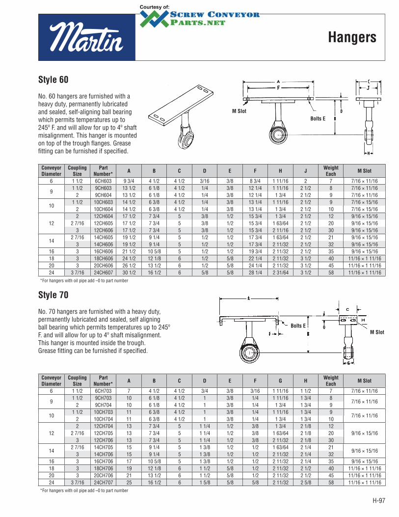
H-97
Hangers
Conveyor
Diameter
Coupling
Size
Part
Number*A B C D E F H J
Weight
EachM Slot
6 1 1/2 6CH603 9 3/4 4 1/2 4 1/2 3/16 3/8 8 3/4 1 11/16 2 7 7/16 × 11/16
91 1/2 9CH603 13 1/2 6 1/8 4 1/2 1/4 3/8 12 1/4 1 11/16 2 1/2 8 7/16 × 11/16
2 9CH604 13 1/2 6 1/8 4 1/2 1/4 3/8 12 1/4 1 3/4 2 1/2 9 7/16 × 11/16
101 1/2 10CH603 14 1/2 6 3/8 4 1/2 1/4 3/8 13 1/4 1 11/16 2 1/2 9 7/16 × 15/16
2 10CH604 14 1/2 6 3/8 4 1/2 1/4 3/8 13 1/4 1 3/4 2 1/2 10 7/16 × 15/16
122 12CH604 17 1/2 7 3/4 5 3/8 1/2 15 3/4 1 3/4 2 1/2 12 9/16 × 15/16
2 7/16 12CH605 17 1/2 7 3/4 5 3/8 1/2 15 3/4 1 63/64 2 1/2 20 9/16 × 15/16 3 12CH606 17 1/2 7 3/4 5 3/8 1/2 15 3/4 2 11/16 2 1/2 30 9/16 × 15/16
142 7/16 14CH605 19 1/2 9 1/4 5 1/2 1/2 17 3/4 1 63/64 2 1/2 21 9/16 × 15/16
3 14CH606 19 1/2 9 1/4 5 1/2 1/2 17 3/4 2 11/32 2 1/2 32 9/16 × 15/16 16 3 16CH606 21 1/2 10 5/8 5 1/2 1/2 19 3/4 2 11/32 2 1/2 35 9/16 × 15/16 18 3 18CH606 24 1/2 12 1/8 6 1/2 5/8 22 1/4 2 11/32 3 1/2 40 11/16 × 1 11/16 20 3 20CH606 26 1/2 13 1/2 6 1/2 5/8 24 1/4 2 11/32 3 1/2 45 11/16 × 1 11/16 24 3 7/16 24CH607 30 1/2 16 1/2 6 5/8 5/8 28 1/4 2 31/64 3 1/2 58 11/16 × 1 11/16
*For hangers with oil pipe add –0 to part number
Conveyor
Diameter
Coupling
Size
Part
Number*A B C D E F G H
Weight
EachM Slot
6 1 1/2 6CH703 7 4 1/2 4 1/2 3/4 3/8 3/16 1 11/16 1 1/2 7 7/16 × 11/16
91 1/2 9CH703 10 6 1/8 4 1/2 1 3/8 1/4 1 11/16 1 3/4 8
7/16 × 11/16 2 9CH704 10 6 1/8 4 1/2 1 3/8 1/4 1 3/4 1 3/4 9
101 1/2 10CH703 11 6 3/8 4 1/2 1 3/8 1/4 1 11/16 1 3/4 9
7/16 × 11/16 2 10CH704 11 6 3/8 4 1/2 1 3/8 1/4 1 3/4 1 3/4 10
122 12CH704 13 7 3/4 5 1 1/4 1/2 3/8 1 3/4 2 1/8 12
9/16 × 15/16 2 7/16 12CH705 13 7 3/4 5 1 1/4 1/2 3/8 1 63/64 2 1/8 203 12CH706 13 7 3/4 5 1 1/4 1/2 3/8 2 11/32 2 1/8 30
142 7/16 14CH705 15 9 1/4 5 1 3/8 1/2 1/2 1 63/64 2 1/4 21
9/16 × 15/16 3 14CH706 15 9 1/4 5 1 3/8 1/2 1/2 2 11/32 2 1/4 32
16 3 16CH706 17 10 5/8 5 1 3/8 1/2 1/2 2 11/32 2 1/4 35 9/16 × 15/16 18 3 18CH706 19 12 1/8 6 1 1/2 5/8 1/2 2 11/32 2 1/2 40 11/16 × 1 11/16 20 3 20CH706 21 13 1/2 6 1 1/2 5/8 1/2 2 11/32 2 1/2 45 11/16 × 1 11/16 24 3 7/16 24CH707 25 16 1/2 6 1 5/8 5/8 5/8 2 11/32 2 5/8 58 11/16 × 1 11/16
*For hangers with oil pipe add –0 to part number
Style 60
No. 60 hangers are furnished with a heavy duty, permanently lubricated and sealed, self-aligning ball bearing which permits temperatures up to 245º F. and will allow for up to 4º shaft misalignment. This hanger is mounted on top of the trough flanges. Grease fitting can be furnished if specified.
Bolts E
M Slot
Style 70
No. 70 hangers are furnished with a heavy duty, permanently lubricated and sealed, self aligning ball bearing which permits temperatures up to 245º F. and will allow for up to 4º shaft misalignment. This hanger is mounted inside the trough. Grease fitting can be furnished if specified.
Bolts E
M Slot
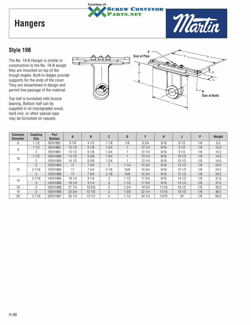
H-98
Hangers
Conveyor
Diameter
Coupling
Size
Part
NumberA B C D F H J P Weight
6 1 1/2 6CH19B3 9 7/8 4 1/2 1 7/8 7/8 8 3/4 9/16 6 1/2 1/8 8.5
91 1/2 9CH19B3 13 1/2 6 1/8 1 3/4 1 12 1/4 9/16 9 1/2 1/8 13.0
2 9CH19B4 13 1/2 6 1/8 1 3/4 1 12 1/4 9/16 9 1/2 1/8 15.5
101 1/2 10CH19B3 14 1/2 6 3/8 1 3/4 1 13 1/4 9/16 10 1/2 1/8 14.0
2 10CH19B4 14 1/2 6 3/8 1 3/4 1 13 1/4 9/16 10 1/2 1/8 14.0
122 12CH19B4 17 7 3/4 2 1 1/4 15 3/4 9/16 12 1/2 1/8 24.0
2 7/16 12CH19B5 17 7 3/4 2 1/8 15/6 15 3/4 9/16 12 1/2 1/8 24.53 12CH19B6 17 7 3/4 2 1/8 15/6 15 3/4 9/16 12 1/2 1/8 24.5
142 7/16 14CH19B5 19 1/4 9 1/4 3 1 1/2 17 3/4 9/16 14 1/2 1/8 37.0
3 14CH19B6 19 1/4 9 1/4 3 1 1/2 17 3/4 9/16 14 1/4 1/8 37.016 3 16CH19B6 21 1/4 10 5/8 3 1 3/4 19 3/4 11/16 16 1/2 1/8 45.018 3 18CH19B6 23 3/4 12 1/8 3 1 5/8 22 1/4 11/16 18 1/2 1/8 48.520 3 7/16 20CH19B7 26 1/4 13 1/2 4 1 1/2 24 1/4 13/16 20 1/8 60.0
Style 19B
The No. 19-B Hanger is similar in construction to the No. 18-B except they are mounted on top of the trough angles. Built-in ledges provide supports for the ends of the cover. They are streamlined in design and permit free passage of the material.
Top half is furnished with bronze bearing. Bottom half can be supplied in oil impregnated wood, hard iron, or other special caps may be furnished on request.
P
Size of Pipe
H
Size of Bolts

H-99
Screw Conveyor Hanger
Bearing Selection Application
Bearing Material
Maximum
Operating
Temperature (°F)
Styles
Available
Material
FDA
Complaint
Self
LubeSome Suggested Uses Comments
WHITE IRON 500° 220 Yes C hemical, Cement, Aggregate
Requires hardened shaft. Can be noisy. Lubrication required in some applications.
ERTALYTE® 200° 220, 216 Yes Food Registered Trademark of Quadrant Engineering Products
GATKE 400° 220, 216 Chemical Fiberglass fabric. Good for higher speeds.
HARD IRON 500° 220 Yes Chemical, Cement, Aggregate Requires Hardened Shaft
CAST HARD IRON 500° 220, 216, 19B
Lime, Cement, Salt, Gypsum
Requires hardened shaft. Can be noisy. Lubrication required in some applications.
WOOD 160° 220, 216, 19B Yes Grain, Feed,
Fertilizer Good general purpose.
BRONZE 850° 220 Yes Grain, Feed, Processing
High quality bearings. High load capacity.
NYLATRON GS 250° 220, 19B YesChemical,
Handling, Grain, Feed
Very low load capacity.
UHMW 225° 220, 216 Yes Yes Food Material USDA approved. Does not swell in water.
STELLITE 1000° 220, 216 Chemical, Cement, Aggregate Requires Stellite insert in shaft.
INDUSTRIAL GRADE
ENGINEERED NYLON160° 220 Yes Grain, Feed,
FertilizerEconomical replacement for wood.
WHITE MELAMINE 190° 220 Yes FoodSuitable for repeat use in food contact applications at temps not exceeding 190°F.
FOOD GRADE
ENGINEERED NYLON300° 220 Yes Yes Food, Grain,
Fertilizer For dry application.
BALL BEARING 180° 60, 70 Non-abrasive applications General purpose use.
HDPE 200° 220 Yes Yes Grain, Feed, Chemical Handling
Recommended for non-abrasive applications
CERAMIC1 1,000° 220, 216 Yes Chemical, Cement, Food Requires hardened shafts.
URETHANE 200° 220 YES Grain, Chemical, Fertilizer Good general purpose.
1 Higher temperature ceramics are available.
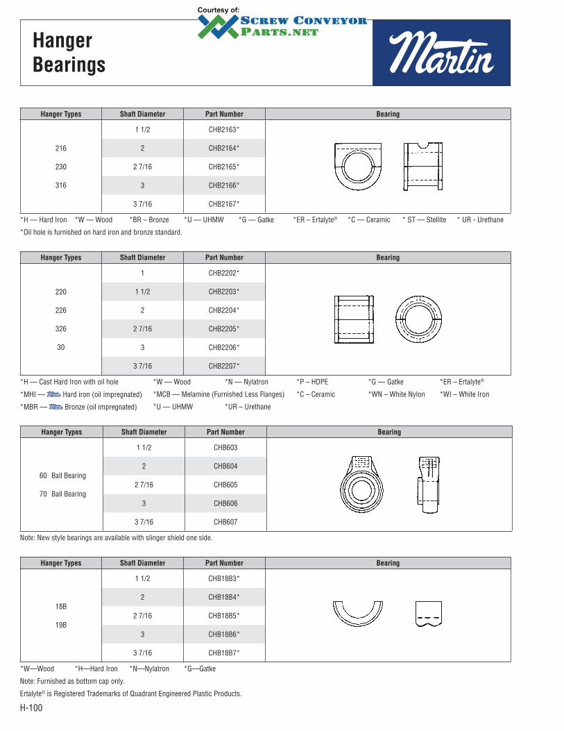
H-100
Hanger
Bearings
Hanger Types Shaft Diameter Part Number Bearing
216
230
316
1 1/2 CHB2163*
2 CHB2164*
2 7/16 CHB2165*
3 CHB2166*
3 7/16 CHB2167*
*H — Hard Iron *W — Wood *BR – Bronze *U — UHMW *G — Gatke *ER – Ertalyte® *C — Ceramic * ST — Stellite * UR - Urethane
*Oil hole is furnished on hard iron and bronze standard.
Hanger Types Shaft Diameter Part Number Bearing
18B
19B
1 1/2 CHB18B3*
2 CHB18B4*
2 7/16 CHB18B5*
3 CHB18B6*
3 7/16 CHB18B7*
*W—Wood *H—Hard Iron *N—Nylatron *G—Gatke
Note: Furnished as bottom cap only.
Ertalyte® is Registered Trademarks of Quadrant Engineered Plastic Products.
Hanger Types Shaft Diameter Part Number Bearing
220
226
326
30
1 CHB2202*
1 1/2 CHB2203*
2 CHB2204*
2 7/16 CHB2205*
3 CHB2206*
3 7/16 CHB2207*
*H — Cast Hard Iron with oil hole *W — Wood *N — Nylatron *P – HDPE *G — Gatke *ER – Ertalyte®
*MHI — Hard iron (oil impregnated) *MCB — Melamine (Furnished Less Flanges) *C – Ceramic *WN – White Nylon *WI – White Iron
*MBR — Bronze (oil impregnated) *U — UHMW *UR – Urethane
Hanger Types Shaft Diameter Part Number Bearing
60
70
Ball Bearing
Ball Bearing
1 1/2 CHB603
2 CHB604
2 7/16 CHB605
3 CHB606
3 7/16 CHB607
Note: New style bearings are available with slinger shield one side.

H-101
Trough Cover
ConveyorDiameter
Cover Thickness16 — 16 GA.14 — 14 GA.12 — 12 GA10 — 10 GA.
Length of Cover
TypeTCP — PlainTCS — Semi FlangedTCF — FlangedTCH — Hip RoofTSC — Shroud
14 TCP 14 -12
It is the responsibility of the contractor, installer, owner and user to install, maintain and operate the conveyor components and conveyor assemblies manufactured and supplied by in such a manner as to comply with the Williams-Steiger Occupational Safety and Health Act and with all state and local laws and ordinances and the American National Standard Institute Safety Code.
FLANGED
COVERS
Most commonly used.Can be supplied with gaskets and butt straps for dust tight applications.Semi-flanged must be furnished if spring clamps are used.
FLAT
COVERSUsually used only to cover conveyor for safety.
FLARED
TROUGH
COVERS
Usually flanged type and heavier gauges because of span.
HIP
ROOF
COVERS
Hip roof covers are similar to conventional flanged covers except they are peaked slightly to form a ridge along the center of the cover. A welded end plate closes the peaked section at each end of the trough while intermediate joints are usually buttstrap connected. Hip roof covers are usually recommended for outdoor installations to prevent accumulation of moisture. They are also often used in applications where a more rigid cover is required.
SHROUD
COVERSUsed to approximate tubular cross section for inclined or feeder applications.
DOMED
COVERS
Domed covers are half circle domes rolled to the same inside diameter as the trough bottom and are flanged for bolting to the trough top rails. They are used where venting of fumes or heat from the material being conveyed is required. End sections have a welded end plate and intermediate joints are buttstrap connected. Vent pipes or suction lines can be attached to the cover.
FEEDER
SHROUDS
Shrouds are used in trough sections of screw feeders to decrease the clearance between the cover and feeder screw to obtain proper feed regulation. Lengths are sufficient to prevent flushing of the majority of materials being handled and gauges are proportioned to trough size and gauge.
Trough
Covers
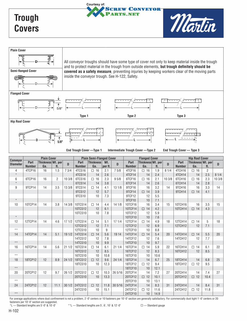
H-102
Trough
Covers
Plain Cover
All conveyor troughs should have some type of cover not only to keep material inside the trough and to protect material in the trough from outside elements, but trough definitely should be
covered as a safety measure, preventing injuries by keeping workers clear of the moving parts inside the conveyor trough. See H-122, Safety.
Semi-flanged Cover
Flanged Cover
Type 1 Type 2 Type 3
Hip Roof Cover
D L5/8"
LL
End Trough Cover —Type 1 Intermediate Trough Cover —Type 2 End Trough Cover — Type 3
Conveyor
Diameter
Plain Cover Plain Semi-Flanged Cover Flanged Cover Hip Roof Cover
Part
Number
Thickness
Ga.
Wt. per
ft.D
Part
Number
Thickness
Ga.
Wt.
per ft.D
Part
Number
Thickness
Ga.
Wt. per
ft.D
Part
Number
Thickness
Ga.
Wt. per
ft.D
4 4TCP16 16 1.5 7 3/4 4TCS16 16 2.1 7 5/8 4TCF16 16 1.9 8 1/4 4TCH16 16 2* 4TCS14 14 2.6 4TCF14 14 2.4 4TCH14 14 2.5 8 1/46 6TCP16 16 2 10 3/8 6TCS16 16 2.3 9 5/8 6TCF16 16 2.1 10 3/8 6TCH16 16 2.3 10 3/8* 6TCS14 14 3.8 6TCF14 14 2.6 6TCH14 14 2.89 9TCP14 14 3.5 13 3/8 9TCS14 14 4.1 13 1/8 9TCF16 16 3.2 14 9TCH16 16 3.3 14
9TCS12 12 5.7 9TCF14 14 3.9 9TCH14 14 4.19TCS10 10 7.3 9TCF12 12 5.5
* 9TCF10 10 7.110 10TCP14 14 3.8 14 3/8 10TCS14 14 4.4 14 1/8 10TCF16 16 3.4 15 10TCH16 16 3.5 15
10TCS12 12 6.1 10TCF14 14 4.2 10TCH14 14 4.310TCS10 10 7.8 10TCF12 12 5.9
* 10TCF10 10 7.612 12TCP14 14 4.6 17 1/2 12TCS14 14 5.1 17 1/4 12TCF14 14 4.9 18 12TCH14 14 5 18
12TCS12 12 7.1 12TCF12 12 6.9 12TCH12 12 7.1** 12TCS10 10 9 12TCF10 10 8.814 14TCP14 14 5.1 19 1/2 14TCS14 14 5.6 19 14 14TCF14 14 5.4 20 14TCH14 14 5.5 20
14TCS12 12 7.8 14TCF12 12 7.6 14TCH12 12 7.7** 14TCS10 10 9.9 14TCF10 10 9.716 16TCP14 14 5.6 21 1/2 16TCS14 14 6.1 21 1/4 16TCF14 14 5.9 22 16TCH14 14 6.1 22
16TCS12 12 8.5 16TCF12 12 8.3 16TCH12 12 8.5** 16TCS10 10 10.8 16TCF10 10 10.618 18TCP12 12 8.9 24 1/2 18TCS12 12 9.6 24 1/4 18TCF14 14 6.7 25 18TCH14 14 6.8 25
18TCS10 10 12.3 18TCF12 12 9.4 18TCH12 12 9.5** 18TCF10 10 12.120 20TCP12 12 9.7 26 1/2 20TCS12 12 10.3 26 5/16 20TCF14 14 7.2 27 20TCH14 14 7.4 27
20TCS10 10 13.3 20TCF12 12 10.1 20TCH12 12 10.4** 20TCF10 10 13.124 24TCP12 12 11.1 30 1/2 24TCS12 12 11.8 30 5/16 24TCF14 14 8.3 31 24TCH14 14 8.4 31
24TCS10 10 15.1 24TCF12 12 11.6 24TCH12 12 11.8** 24TCF10 10 14.9
For average applications where dust confinement is not a problem, 2'-0" centers or 10 fasteners per 10'-0" section are generally satisfactory. For commercially dust tight 1'-0" centers or 20 fasteners per 10'-0" section are suggested.*L — Standard lengths are 5'-0" & 10'-0" **L — Standard lengths are 5', 6', 10' & 12'-0" — Standard gauge
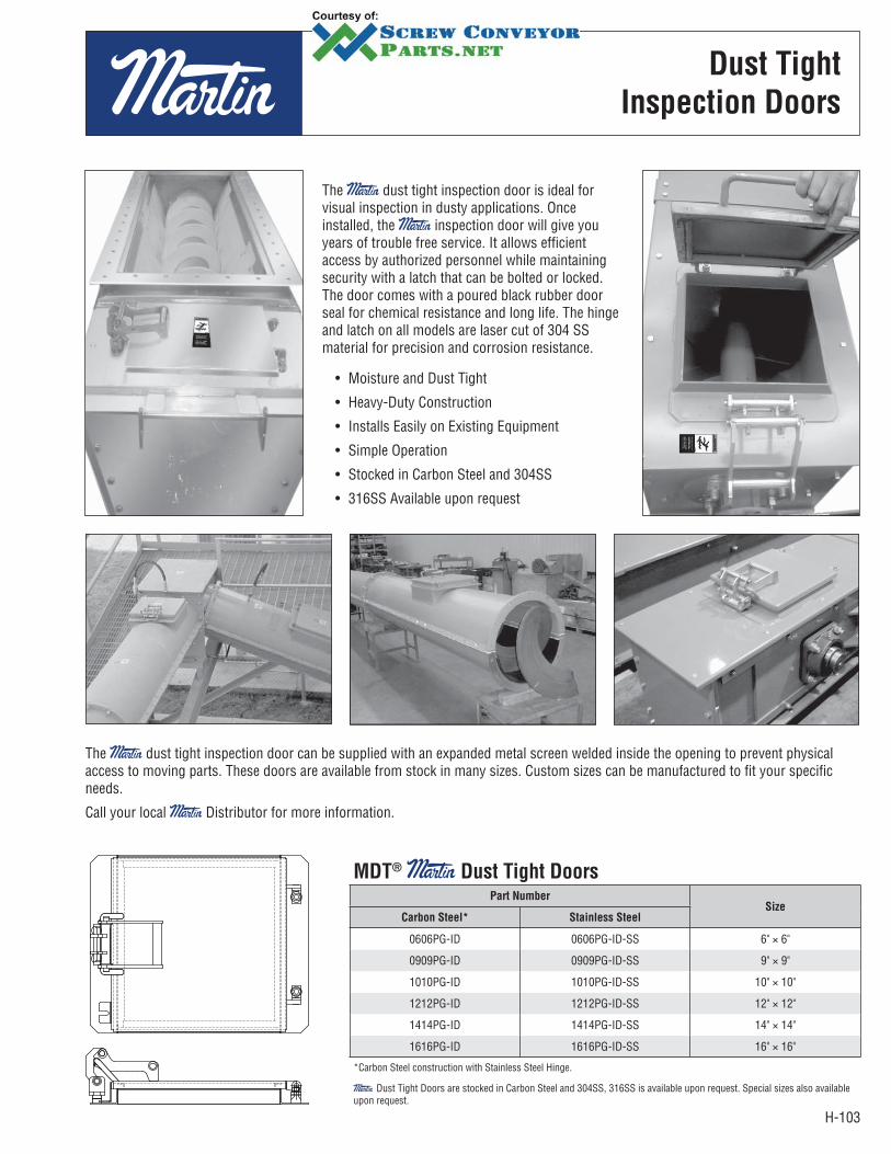
H-103
Dust Tight
Inspection Doors
The dust tight inspection door is ideal for visual inspection in dusty applications. Once installed, the inspection door will give you years of trouble free service. It allows efficient access by authorized personnel while maintaining security with a latch that can be bolted or locked. The door comes with a poured black rubber door seal for chemical resistance and long life. The hinge and latch on all models are laser cut of 304 SS material for precision and corrosion resistance.
• Moisture and Dust Tight
• Heavy-Duty Construction
• Installs Easily on Existing Equipment
• Simple Operation
• Stocked in Carbon Steel and 304SS
• 316SS Available upon request
The dust tight inspection door can be supplied with an expanded metal screen welded inside the opening to prevent physical access to moving parts. These doors are available from stock in many sizes. Custom sizes can be manufactured to fit your specific needs.
Call your local Distributor for more information.
MDT® Dust Tight DoorsPart Number
SizeCarbon Steel* Stainless Steel
0606PG-ID 0606PG-ID-SS 6" × 6"
0909PG-ID 0909PG-ID-SS 9" × 9"
1010PG-ID 1010PG-ID-SS 10" × 10"
1212PG-ID 1212PG-ID-SS 12" × 12"
1414PG-ID 1414PG-ID-SS 14" × 14"
1616PG-ID 1616PG-ID-SS 16" × 16"
*Carbon Steel construction with Stainless Steel Hinge.
Dust Tight Doors are stocked in Carbon Steel and 304SS, 316SS is available upon request. Special sizes also available upon request.

H-104
Conveyor
Diameter
Part Number
Weight B
C E
F G H J K LFixed Inlet
Detachable
Inlet
Fixed
Inlet
Detachable
Inlet
Fixed
Inlet
Detachable
Inlet
4 4CIF 4CID 1.8 5 7 1/2 7 1/2 3/8 3/8 2 1/4 — 2 1/4 1 1/4 3/16 1/46 6CIF 6CID 5.0 7 10 10 11/16 11/16 2 13/16 — 3 1 1/2 3/16 3/89 9CIF 9CID 6.8 10 13 13 1/2 1/2 4 — 4 1 1/2 3/16 3/810 10CIF 10CID 7.4 11 14 1/4 14 1/4 5/8 5/8 4 5/16 — 4 3/8 1 1/2 3/16 3/8 12 12CIF 12CID 12.1 13 17 1/4 17 1/4 3/4 7/8 5 1/8 — 5 1/4 2 3/16 3/814 14CIF 14CID 13.7 15 19 1/4 19 1/4 3/4 7/8 3 1/2 3 1/2 3 1/2 2 3/16 3/816 16CIF 16CID 15.8 17 21 1/4 21 1/4 3/4 7/8 3 3/4 4 4 2 3/16 3/818 18CIF 18CID 29.0 19 24 1/4 24 1/4 1 1 1/8 4 7/16 4 3/8 4 3/8 2 1/2 3/16 1/220 20CIF 20CID 31.8 21 26 1/4 26 1/4 1 1 1/8 4 7/8 4 3/4 4 3/4 2 1/2 3/16 1/224 24CIF 24CID 37.2 25 30 1/4 30 1/4 1 1 1/8 5 5/8 5 5/8 5 1/2 2 1/2 3/16 1/2
Clamp No. A B C D E F G H J Wt.
SPC-1 5/16 3/16 5/16 2 1 1/4 1 5/16 3 7/8 9/32 .38
Clamp No. A B C D E F G H J Wt.
SPCA-1 11/16 1/2 3/16 1 1/2 1 9/16 3/8 7/8 3/8 1 1/4 .50
Clamp No. A B C D E F G J Wt.
CSC-2 2 1/4 1 1 3/16 1 7/16 5/16 3/8 1/2 .42 .50
ConveyorPart
Number
No. Required per
10' SectionA B C D E F G
4 – 24 QTC 6 to 8 7 13/16 2 15/16 1 25/32 2 1 1/4 5/16 5/8
Flanged Conveyor Inlets
The two styles of flanged conveyor inlets are designed for either bolting or welding to flat or flanged conveyor trough cover. The inlet size and bolt arrangement is the same as the standard conveyor discharge spout.
Spring Clamps
Spring Clamps are used to attach plain and semi-flanged covers to trough. These clamps are normally riveted to the trough flange and will pivot to allow removal of cover.
Spring Clamps with Cover Bracket
Spring Clamps with cover brackets are designed to attach to the top side of semi-flanged and plain covers.
Screw Clamps
Screw Clamps are a simple and effective means of attaching flanged or flat covers to trough.Screw Clamps available in mild steel, stainless steel and zinc plated.
Toggle Clamps
Quick acting toggle clamps are used to attach covers for quick accessibility. Normally this type clamp is attached by welding the front or top of clamp to the trough and can be adjusted to fit all sizes of trough, while allowing 90° to clear working area.
Cover
Accessories
Detachable
Type
L Bolts
Fixed
Typev
Cover GasketsConveyor
Diameter
Size
Red Rubber Sponge Rubber *White Rubber
4.6RR125 SP125 WN125
1/8 × 1 1/4 1 1/8 × 1 1/4 1/8 × 1 1/4
9,10RR150 SP150 WN150
1/8 × 1 1/2 1/8 × 1 1/2 1/8 × 1 1/212, 14,
16RR200 SP200 WN2001/8 × 2 1/8 × 2 1/8 × 2
18, 20, 24
RR250 SP250 WN2501/8 × 2 1/2 1/8 × 2 1/2 1/8 × 2 1/2
*FDA Approved
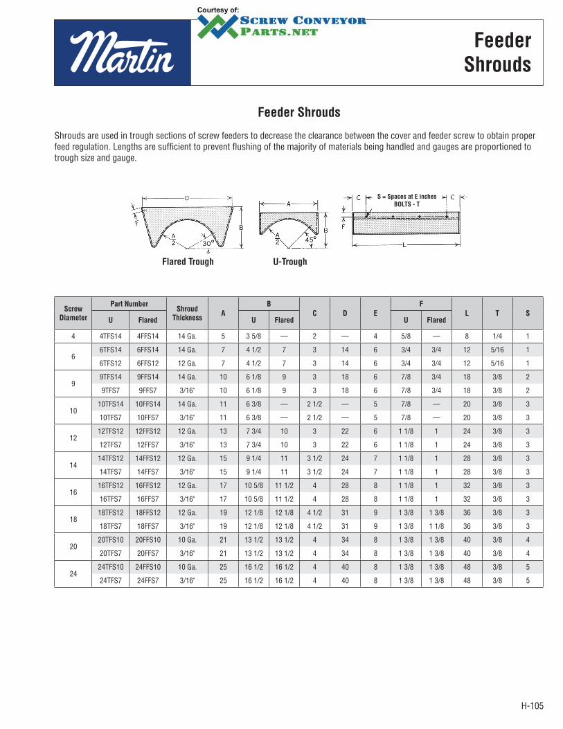
H-105
Screw
Diameter
Part NumberShroud
ThicknessA
B
C D E
F
L T SU Flared U Flared U Flared
4 4TFS14 4FFS14 14 Ga. 5 3 5/8 — 2 — 4 5/8 — 8 1/4 1
66TFS14 6FFS14 14 Ga. 7 4 1/2 7 3 14 6 3/4 3/4 12 5/16 1
6TFS12 6FFS12 12 Ga. 7 4 1/2 7 3 14 6 3/4 3/4 12 5/16 1
99TFS14 9FFS14 14 Ga. 10 6 1/8 9 3 18 6 7/8 3/4 18 3/8 2
9TFS7 9FFS7 3/16" 10 6 1/8 9 3 18 6 7/8 3/4 18 3/8 2
1010TFS14 10FFS14 14 Ga. 11 6 3/8 — 2 1/2 — 5 7/8 — 20 3/8 3
10TFS7 10FFS7 3/16" 11 6 3/8 — 2 1/2 — 5 7/8 — 20 3/8 3
1212TFS12 12FFS12 12 Ga. 13 7 3/4 10 3 22 6 1 1/8 1 24 3/8 3
12TFS7 12FFS7 3/16" 13 7 3/4 10 3 22 6 1 1/8 1 24 3/8 3
1414TFS12 14FFS12 12 Ga. 15 9 1/4 11 3 1/2 24 7 1 1/8 1 28 3/8 3
14TFS7 14FFS7 3/16" 15 9 1/4 11 3 1/2 24 7 1 1/8 1 28 3/8 3
1616TFS12 16FFS12 12 Ga. 17 10 5/8 11 1/2 4 28 8 1 1/8 1 32 3/8 3
16TFS7 16FFS7 3/16" 17 10 5/8 11 1/2 4 28 8 1 1/8 1 32 3/8 3
1818TFS12 18FFS12 12 Ga. 19 12 1/8 12 1/8 4 1/2 31 9 1 3/8 1 3/8 36 3/8 3
18TFS7 18FFS7 3/16" 19 12 1/8 12 1/8 4 1/2 31 9 1 3/8 1 1/8 36 3/8 3
2020TFS10 20FFS10 10 Ga. 21 13 1/2 13 1/2 4 34 8 1 3/8 1 3/8 40 3/8 4
20TFS7 20FFS7 3/16" 21 13 1/2 13 1/2 4 34 8 1 3/8 1 3/8 40 3/8 4
2424TFS10 24FFS10 10 Ga. 25 16 1/2 16 1/2 4 40 8 1 3/8 1 3/8 48 3/8 5
24TFS7 24FFS7 3/16" 25 16 1/2 16 1/2 4 40 8 1 3/8 1 3/8 48 3/8 5
Feeder Shrouds
Shrouds are used in trough sections of screw feeders to decrease the clearance between the cover and feeder screw to obtain proper feed regulation. Lengths are sufficient to prevent flushing of the majority of materials being handled and gauges are proportioned to trough size and gauge.
Feeder
Shrouds
Flared Trough U-Trough
S = Spaces at E inches
BOLTS - T
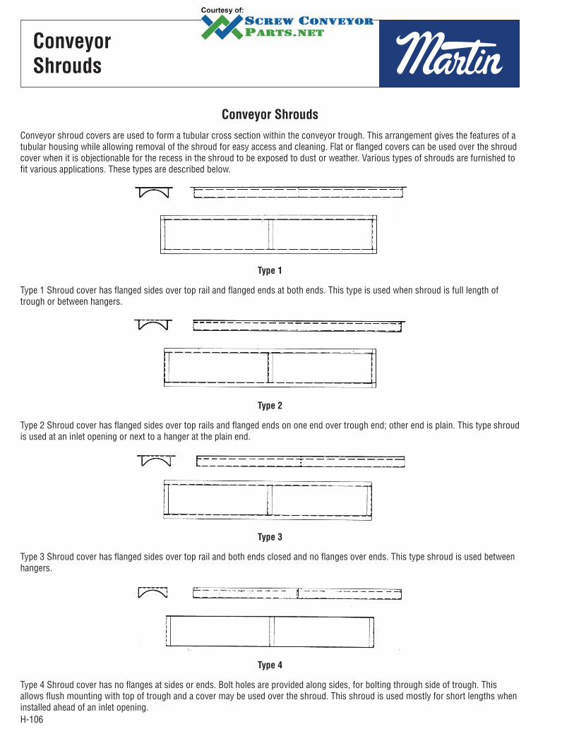
H-106
Conveyor Shrouds
Conveyor shroud covers are used to form a tubular cross section within the conveyor trough. This arrangement gives the features of a tubular housing while allowing removal of the shroud for easy access and cleaning. Flat or flanged covers can be used over the shroud cover when it is objectionable for the recess in the shroud to be exposed to dust or weather. Various types of shrouds are furnished to fit various applications. These types are described below.
Type 1
Type 1 Shroud cover has flanged sides over top rail and flanged ends at both ends. This type is used when shroud is full length of trough or between hangers.
Type 2
Type 2 Shroud cover has flanged sides over top rails and flanged ends on one end over trough end; other end is plain. This type shroud is used at an inlet opening or next to a hanger at the plain end.
Type 3
Type 3 Shroud cover has flanged sides over top rail and both ends closed and no flanges over ends. This type shroud is used between hangers.
Type 4
Type 4 Shroud cover has no flanges at sides or ends. Bolt holes are provided along sides, for bolting through side of trough. This allows flush mounting with top of trough and a cover may be used over the shroud. This shroud is used mostly for short lengths when installed ahead of an inlet opening.
Conveyor
Shrouds
H-107
Special
Features
SPECIAL FEATURES PAGE
COVERS . . . . . . . . . . . . . . . . . . . . . . . . . . . . . . . . . . . . . . . . . . . . . . . . . . . . . . . . . . . . . . . . . . . . . . . . . . . . . . . . . . . . H-108
TROUGH ENDS . . . . . . . . . . . . . . . . . . . . . . . . . . . . . . . . . . . . . . . . . . . . . . . . . . . . . . . . . . . . . . . . . . . . . . . . . . . . . . H-109
TROUGH . . . . . . . . . . . . . . . . . . . . . . . . . . . . . . . . . . . . . . . . . . . . . . . . . . . . . . . . . . . . . . . . . . . . . . . . . . . . . . . . . . . H-110
CONVEYOR SCREWS . . . . . . . . . . . . . . . . . . . . . . . . . . . . . . . . . . . . . . . . . . . . . . . . . . . . . . . . . . . . . . . . . . . . . . . . . . H-113
DISCHARGES . . . . . . . . . . . . . . . . . . . . . . . . . . . . . . . . . . . . . . . . . . . . . . . . . . . . . . . . . . . . . . . . . . . . . . . . . . . . . . . . H-118
INLET . . . . . . . . . . . . . . . . . . . . . . . . . . . . . . . . . . . . . . . . . . . . . . . . . . . . . . . . . . . . . . . . . . . . . . . . . . . . . . . . . . . . H-119
Special Features
The information presented in this section gives descriptions and functions of the most commonly used special features available in the design of conveyor systems.
These special features will greatly broaden the range of uses for screw conveyor when added to the many standard features available. Standard features and components are always more desirable and practical in the design of a screw conveyor system; however, one or more of these special features may sometimes be required in special applications for a workable or more efficient system.
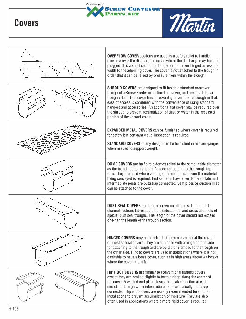
H-108
OVERFLOW COVER sections are used as a safety relief to handle overflow over the discharge in cases where the discharge may become plugged. It is a short section of flanged or flat cover hinged across the width to the adjoining cover. The cover is not attached to the trough in order that it can be raised by pressure from within the trough.
SHROUD COVERS are designed to fit inside a standard conveyor trough of a Screw Feeder or inclined conveyor, and create a tubular trough effect. This cover has an advantage over tubular trough in that ease of access is combined with the convenience of using standard hangers and accessories. An additional flat cover may be required over the shroud to prevent accumulation of dust or water in the recessed portion of the shroud cover.
EXPANDED METAL COVERS can be furnished where cover is required for safety but constant visual inspection is required.
STANDARD COVERS of any design can be furnished in heavier gauges, when needed to support weight.
DOME COVERS are half circle domes rolled to the same inside diameter as the trough bottom and are flanged for bolting to the trough top rails. They are used where venting of fumes or heat from the material being conveyed is required. End sections have a welded end plate and intermediate joints are buttstrap connected. Vent pipes or suction lines can be attached to the cover.
DUST SEAL COVERS are flanged down on all four sides to match channel sections fabricated on the sides, ends, and cross channels of special dust seal troughs. The length of the cover should not exceed one-half the length of the trough section.
HINGED COVERS may be constructed from conventional flat covers or most special covers. They are equipped with a hinge on one side for attaching to the trough and are bolted or clamped to the trough on the other side. Hinged covers are used in applications where it is not desirable to have a loose cover, such as in high areas above walkways where the cover might fall.
HIP ROOF COVERS are similar to conventional flanged covers except they are peaked slightly to form a ridge along the center of the cover. A welded end plate closes the peaked section at each end of the trough while intermediate joints are usually buttstrap connected. Hip roof covers are usually recommended for outdoor installations to prevent accumulation of moisture. They are also often used in applications where a more rigid cover is required.
Covers

H-109
Trough
Ends
SHELF-TYPE TROUGH ENDS are furnished with outboard bearing pedestals for mounting pillow block bearings. The bearings are mounted away from the trough end plate allowing ample room to protect the bearing when handling abrasive or hot materials. This arrangement allows the use of most any type shaft seal desired. Either one or two bearings can be used.
BLIND TROUGH ENDS are used on the tail end (normally the inlet end) of a conveyor, when sealing the end shaft is extremely difficult. A hanger is used inside the trough to support the tail shaft without the shaft projecting through the trough end.
A blind trough end plate can also be furnished with a dead shaft welded to the end plate. For this type the screw is bushed with an antifriction bearing to carry the radial load of the screw. When required, a grease fitting can be furnished through the dead shaft for lubricating the bearing.
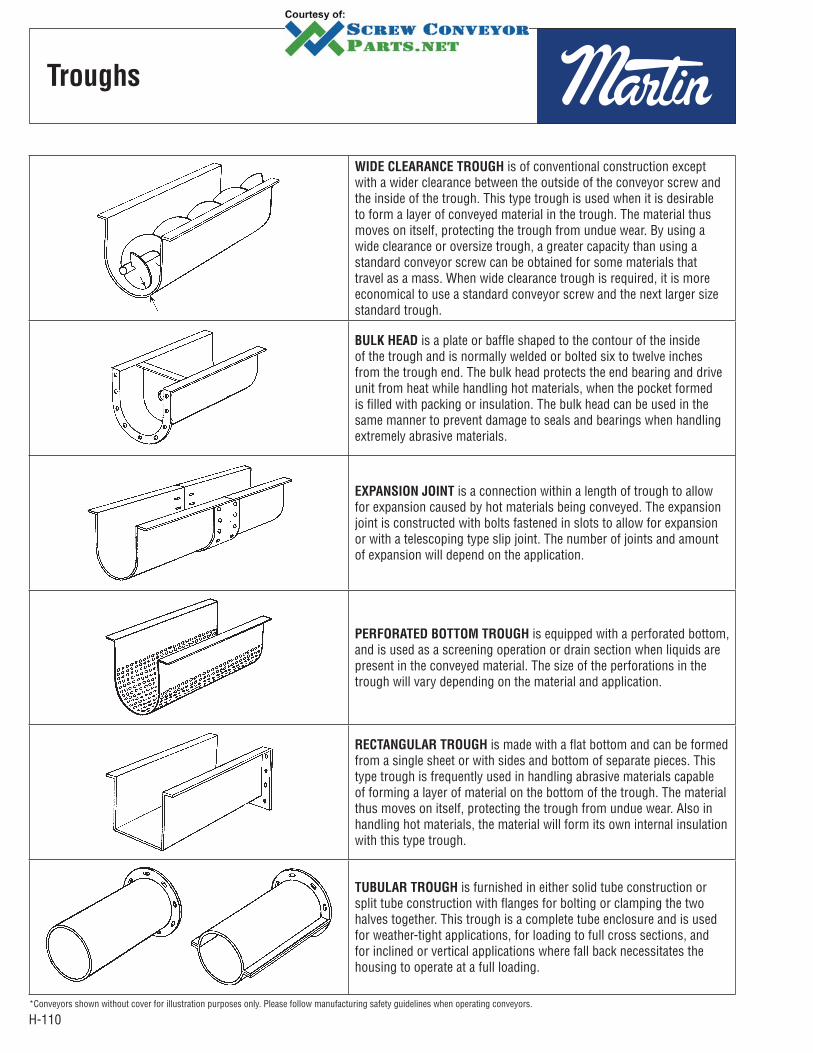
H-110
WIDE CLEARANCE TROUGH is of conventional construction except with a wider clearance between the outside of the conveyor screw and the inside of the trough. This type trough is used when it is desirable to form a layer of conveyed material in the trough. The material thus moves on itself, protecting the trough from undue wear. By using a wide clearance or oversize trough, a greater capacity than using a standard conveyor screw can be obtained for some materials that travel as a mass. When wide clearance trough is required, it is more economical to use a standard conveyor screw and the next larger size standard trough.
BULK HEAD is a plate or baffle shaped to the contour of the inside of the trough and is normally welded or bolted six to twelve inches from the trough end. The bulk head protects the end bearing and drive unit from heat while handling hot materials, when the pocket formed is filled with packing or insulation. The bulk head can be used in the same manner to prevent damage to seals and bearings when handling extremely abrasive materials.
EXPANSION JOINT is a connection within a length of trough to allow for expansion caused by hot materials being conveyed. The expansion joint is constructed with bolts fastened in slots to allow for expansion or with a telescoping type slip joint. The number of joints and amount of expansion will depend on the application.
PERFORATED BOTTOM TROUGH is equipped with a perforated bottom, and is used as a screening operation or drain section when liquids are present in the conveyed material. The size of the perforations in the trough will vary depending on the material and application.
RECTANGULAR TROUGH is made with a flat bottom and can be formed from a single sheet or with sides and bottom of separate pieces. This type trough is frequently used in handling abrasive materials capable of forming a layer of material on the bottom of the trough. The material thus moves on itself, protecting the trough from undue wear. Also in handling hot materials, the material will form its own internal insulation with this type trough.
TUBULAR TROUGH is furnished in either solid tube construction or split tube construction with flanges for bolting or clamping the two halves together. This trough is a complete tube enclosure and is used for weather-tight applications, for loading to full cross sections, and for inclined or vertical applications where fall back necessitates the housing to operate at a full loading.
*Conveyors shown without cover for illustration purposes only. Please follow manufacturing safety guidelines when operating conveyors.
Troughs

H-111
CLOSE CLEARANCE TROUGH is of conventional construction except with a closer clearance between the outside of the conveyor screw and the inside of the trough. This type trough leaves less material in the trough and is often used when a greater clean-out of conveyed material is required. This type trough also minimizes fall back of certain materials in an inclined conveyor.
DROP BOTTOM TROUGH is equipped with either a bolted or clamped and completely removable drop bottom, or hinged on one side with bolts or clamps on the opposite side. This design offers ease in cleaning of the trough and screw conveyor, and is often used when handling food products where internal inspection and cleaning of the screw conveyor is necessary.
DUST SEAL TROUGH (Sometimes referred to as SAND SEAL TROUGH) has Z-bar top flanges and formed channel cross members making a continuous channel pocket around the top of the trough into which a special flanged cover is set. The channel is filled with sand or dust of the product being conveyed, thus creating an effective seal against the escape of dust from within the conveyor.
CHANNEL SIDE TROUGH is made with separate detachable trough bottoms, bolted or clamped to formed or rolled steel channels. The channels may be of any reasonable length to span widely spaced supports. This type of trough is occasionally used for easy replacement of trough bottoms, and to facilitate repairs when conveyor screw and hangers are not accessible from the top. The channel side trough can also be used without a bottom for filling bins and hoppers.
HIGH SIDE TROUGH is of conventional construction except that the trough sides extend higher than standard from the center line to the top of the trough. This type trough is frequently used in conveying materials which mat together and travel as a mass on top of the conveyor screw. High side trough will confine this type material in the trough, but still affords the necessary expansion room.
JACKETED TROUGH consists of a formed jacket continuously welded to the trough. This type trough is widely used for heating, drying or cooling of materials. Pipe connections are provided for supply and discharge of the heating or cooling media. Special construction must be provided for higher pressures.
*Conveyors shown without cover for illustration purposes only. Please follow manufacturing safety guidelines when operating conveyors.
Troughs
Close
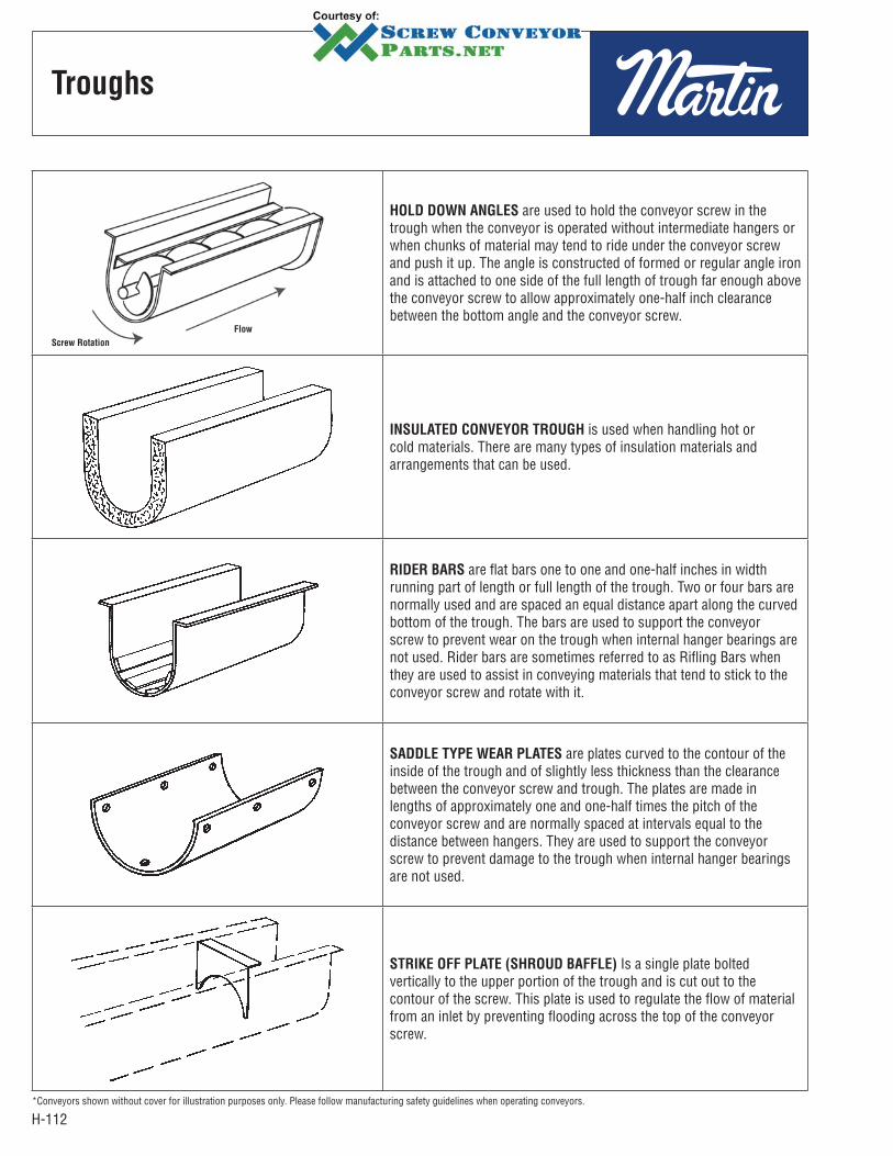
H-112
Troughs
HOLD DOWN ANGLES are used to hold the conveyor screw in the trough when the conveyor is operated without intermediate hangers or when chunks of material may tend to ride under the conveyor screw and push it up. The angle is constructed of formed or regular angle iron and is attached to one side of the full length of trough far enough above the conveyor screw to allow approximately one-half inch clearance between the bottom angle and the conveyor screw.
INSULATED CONVEYOR TROUGH is used when handling hot or cold materials. There are many types of insulation materials and arrangements that can be used.
RIDER BARS are flat bars one to one and one-half inches in width running part of length or full length of the trough. Two or four bars are normally used and are spaced an equal distance apart along the curved bottom of the trough. The bars are used to support the conveyor screw to prevent wear on the trough when internal hanger bearings are not used. Rider bars are sometimes referred to as Rifling Bars when they are used to assist in conveying materials that tend to stick to the conveyor screw and rotate with it.
SADDLE TYPE WEAR PLATES are plates curved to the contour of the inside of the trough and of slightly less thickness than the clearance between the conveyor screw and trough. The plates are made in lengths of approximately one and one-half times the pitch of the conveyor screw and are normally spaced at intervals equal to the distance between hangers. They are used to support the conveyor screw to prevent damage to the trough when internal hanger bearings are not used.
STRIKE OFF PLATE (SHROUD BAFFLE) Is a single plate bolted vertically to the upper portion of the trough and is cut out to the contour of the screw. This plate is used to regulate the flow of material from an inlet by preventing flooding across the top of the conveyor screw.
*Conveyors shown without cover for illustration purposes only. Please follow manufacturing safety guidelines when operating conveyors.
Screw Rotation
Flow

H-113
Conveyor
Screws
WEAR FLIGHTS, or wearing shoes, attached with countersunk bolts to the carrying side of conveyor screw flights are used for handling highly abrasive materials and are easily replaceable.
QUICK DETACHABLE KEY CONVEYOR SCREW is designed for easy removal from the conveyor trough. Each section of screw is provided with a removable key located at one end of the pipe. By removing this key, a conveyor screw section and coupling with a hanger can be quickly removed without disturbing other components.
HARD SURFACED FLIGHTS sometimes called abrasive resistant conveyors can be furnished using one of many hardsurfacing processes. The hard surfaced area is normally an outer portion of the face of the flight on the carrying side of the conveyor screw. This process is applied to the conveyor screw to resist wear when handling highly abrasive materials.
SPLIT FLIGHT COUPLINGS permit installation or removal of individual sections of conveyor screw without disturbing adjoining sections. When they are installed on both sides of each hanger, sections of screw can be removed without disturbing the hangers. These must be furnished complete with matching shafts.
NOTE: Weld-on type
normally 1/16" thick.
Width of Application Chart
Screw
Diameter
Standard Width of
Application
6 19 1 1/212 214 216 2 1/218 2 1/220 324 3
Helicoid Sectional
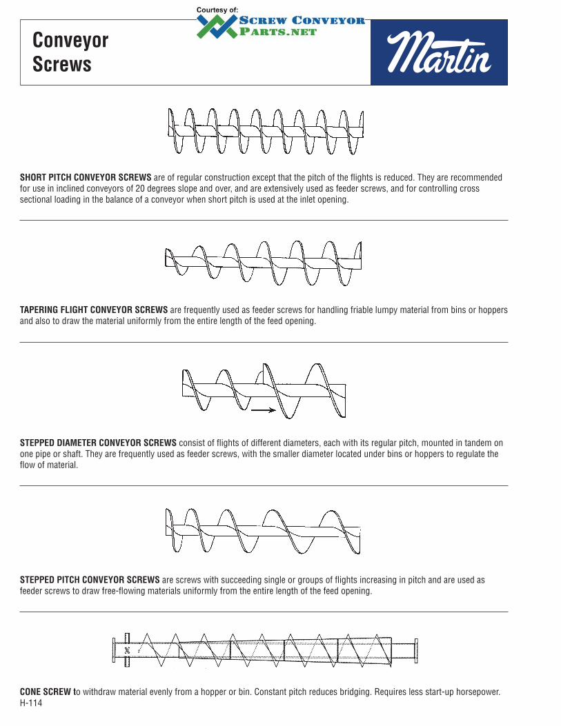
H-114
Conveyor
Screws
SHORT PITCH CONVEYOR SCREWS are of regular construction except that the pitch of the flights is reduced. They are recommended for use in inclined conveyors of 20 degrees slope and over, and are extensively used as feeder screws, and for controlling cross sectional loading in the balance of a conveyor when short pitch is used at the inlet opening.
TAPERING FLIGHT CONVEYOR SCREWS are frequently used as feeder screws for handling friable lumpy material from bins or hoppers and also to draw the material uniformly from the entire length of the feed opening.
STEPPED DIAMETER CONVEYOR SCREWS consist of flights of different diameters, each with its regular pitch, mounted in tandem on one pipe or shaft. They are frequently used as feeder screws, with the smaller diameter located under bins or hoppers to regulate the flow of material.
STEPPED PITCH CONVEYOR SCREWS are screws with succeeding single or groups of flights increasing in pitch and are used as feeder screws to draw free-flowing materials uniformly from the entire length of the feed opening.
CONE SCREW to withdraw material evenly from a hopper or bin. Constant pitch reduces bridging. Requires less start-up horsepower.
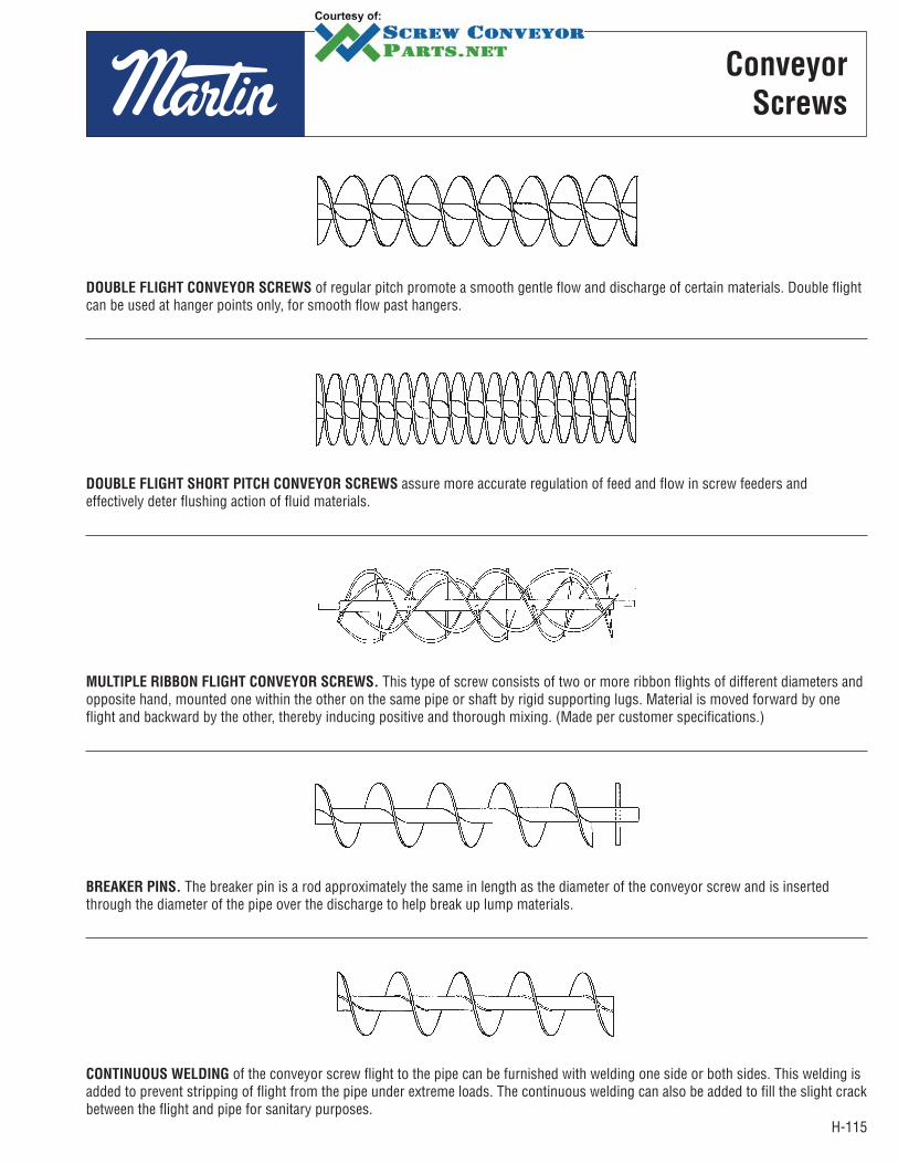
H-115
DOUBLE FLIGHT CONVEYOR SCREWS of regular pitch promote a smooth gentle flow and discharge of certain materials. Double flight can be used at hanger points only, for smooth flow past hangers.
DOUBLE FLIGHT SHORT PITCH CONVEYOR SCREWS assure more accurate regulation of feed and flow in screw feeders and effectively deter flushing action of fluid materials.
MULTIPLE RIBBON FLIGHT CONVEYOR SCREWS. This type of screw consists of two or more ribbon flights of different diameters and opposite hand, mounted one within the other on the same pipe or shaft by rigid supporting lugs. Material is moved forward by one flight and backward by the other, thereby inducing positive and thorough mixing. (Made per customer specifications.)
BREAKER PINS. The breaker pin is a rod approximately the same in length as the diameter of the conveyor screw and is inserted through the diameter of the pipe over the discharge to help break up lump materials.
CONTINUOUS WELDING of the conveyor screw flight to the pipe can be furnished with welding one side or both sides. This welding is added to prevent stripping of flight from the pipe under extreme loads. The continuous welding can also be added to fill the slight crack between the flight and pipe for sanitary purposes.
Conveyor
Screws

H-116
Conveyor
Screws
BEARING SHOES (Nylon, Teflon, Brass, and other bearing type materials.) Bearing shoes are used in place of internal bearings and are bolted to the conveyor screw. They are made from bearing type material, and when attached to the conveyor screw flight, the bearing shoe projects beyond the outer edge of flighting and rotates with the screw thereby preventing metal to metal contact between the conveyor screw and the trough. The bearing shoes extend around the helix slightly more than one pitch and are spaced along the screw at approximately the same intervals as internal bearings.
EXTERNAL SLEEVES OR BOLT PADS are added to the outside diameter of conveyor screw pipe at the end where the couplings are attached to reinforce the pipe at the bolt area.
KICKER BARS are flat bars projecting from the conveyor screw pipe extending to the outside diameter of the screw over the discharge spout and are used to assist the discharge of materials.
MULTIPLE HOLE DRILLING of the conveyor screw pipe and shafts will increase the torque rating of the bolted sections.
External Sleeves Bolt Pads
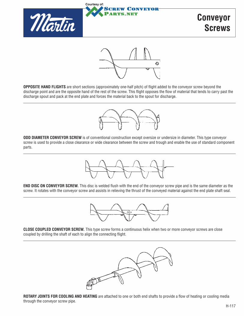
H-117
OPPOSITE HAND FLIGHTS are short sections (approximately one-half pitch) of flight added to the conveyor screw beyond the discharge point and are the opposite hand of the rest of the screw. This flight opposes the flow of material that tends to carry past the discharge spout and pack at the end plate and forces the material back to the spout for discharge.
ODD DIAMETER CONVEYOR SCREW is of conventional construction except oversize or undersize in diameter. This type conveyor screw is used to provide a close clearance or wide clearance between the screw and trough and enable the use of standard component parts.
END DISC ON CONVEYOR SCREW. This disc is welded flush with the end of the conveyor screw pipe and is the same diameter as the screw. It rotates with the conveyor screw and assists in relieving the thrust of the conveyed material against the end plate shaft seal.
CLOSE COUPLED CONVEYOR SCREW. This type screw forms a continuous helix when two or more conveyor screws are close coupled by drilling the shaft of each to align the connecting flight.
ROTARY JOINTS FOR COOLING AND HEATING are attached to one or both end shafts to provide a flow of heating or cooling media through the conveyor screw pipe.
Conveyor
Screws
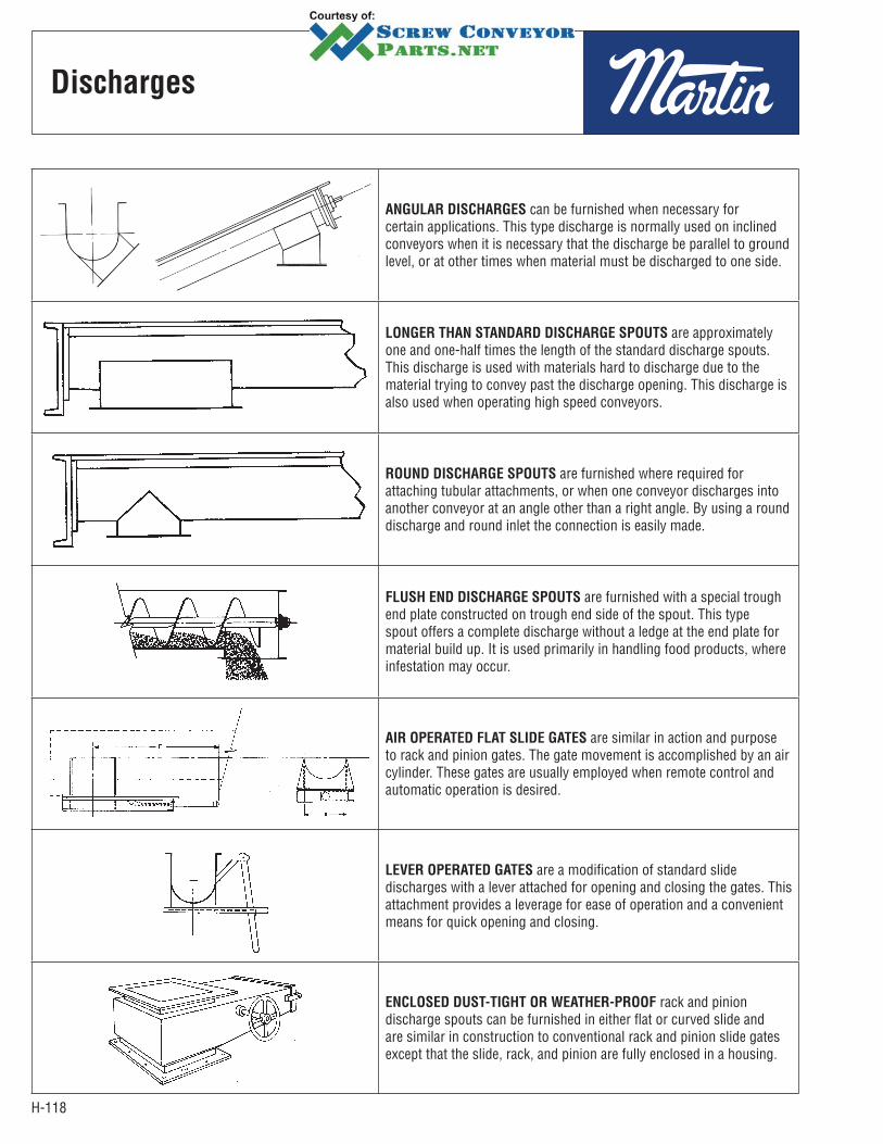
H-118
Discharges
ANGULAR DISCHARGES can be furnished when necessary for certain applications. This type discharge is normally used on inclined conveyors when it is necessary that the discharge be parallel to ground level, or at other times when material must be discharged to one side.
LONGER THAN STANDARD DISCHARGE SPOUTS are approximately one and one-half times the length of the standard discharge spouts. This discharge is used with materials hard to discharge due to the material trying to convey past the discharge opening. This discharge is also used when operating high speed conveyors.
ROUND DISCHARGE SPOUTS are furnished where required for attaching tubular attachments, or when one conveyor discharges into another conveyor at an angle other than a right angle. By using a round discharge and round inlet the connection is easily made.
FLUSH END DISCHARGE SPOUTS are furnished with a special trough end plate constructed on trough end side of the spout. This type spout offers a complete discharge without a ledge at the end plate for material build up. It is used primarily in handling food products, where infestation may occur.
AIR OPERATED FLAT SLIDE GATES are similar in action and purpose to rack and pinion gates. The gate movement is accomplished by an air cylinder. These gates are usually employed when remote control and automatic operation is desired.
LEVER OPERATED GATES are a modification of standard slide discharges with a lever attached for opening and closing the gates. This attachment provides a leverage for ease of operation and a convenient means for quick opening and closing.
ENCLOSED DUST-TIGHT OR WEATHER-PROOF rack and pinion discharge spouts can be furnished in either flat or curved slide and are similar in construction to conventional rack and pinion slide gates except that the slide, rack, and pinion are fully enclosed in a housing.
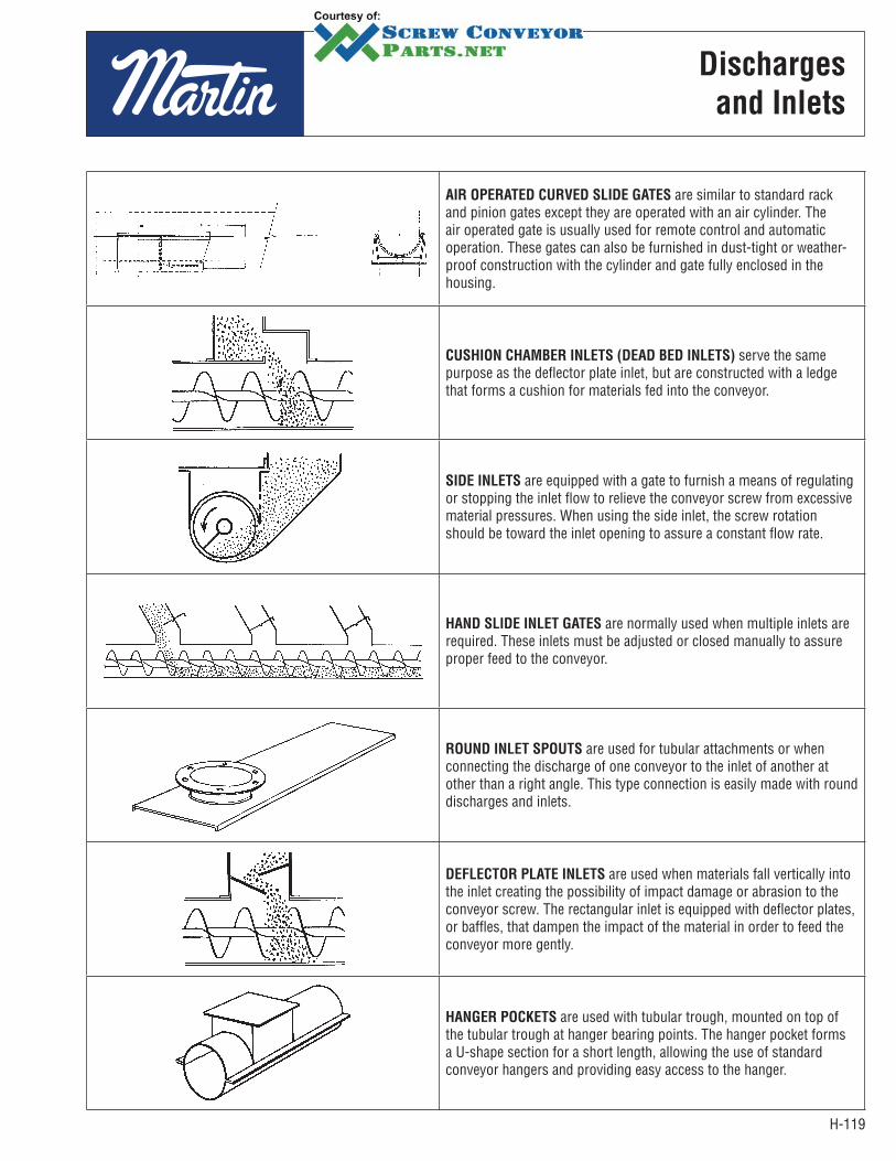
H-119
Discharges
and Inlets
AIR OPERATED CURVED SLIDE GATES are similar to standard rack and pinion gates except they are operated with an air cylinder. The air operated gate is usually used for remote control and automatic operation. These gates can also be furnished in dust-tight or weather-proof construction with the cylinder and gate fully enclosed in the housing.
CUSHION CHAMBER INLETS (DEAD BED INLETS) serve the same purpose as the deflector plate inlet, but are constructed with a ledge that forms a cushion for materials fed into the conveyor.
SIDE INLETS are equipped with a gate to furnish a means of regulating or stopping the inlet flow to relieve the conveyor screw from excessive material pressures. When using the side inlet, the screw rotation should be toward the inlet opening to assure a constant flow rate.
HAND SLIDE INLET GATES are normally used when multiple inlets are required. These inlets must be adjusted or closed manually to assure proper feed to the conveyor.
ROUND INLET SPOUTS are used for tubular attachments or when connecting the discharge of one conveyor to the inlet of another at other than a right angle. This type connection is easily made with round discharges and inlets.
DEFLECTOR PLATE INLETS are used when materials fall vertically into the inlet creating the possibility of impact damage or abrasion to the conveyor screw. The rectangular inlet is equipped with deflector plates, or baffles, that dampen the impact of the material in order to feed the conveyor more gently.
HANGER POCKETS are used with tubular trough, mounted on top of the tubular trough at hanger bearing points. The hanger pocket forms a U-shape section for a short length, allowing the use of standard conveyor hangers and providing easy access to the hanger.

H-120
Installation
& Maintenance
INSTALLATION AND MAINTENANCE PAGE
INSTALLATION AND ERECTION . . . . . . . . . . . . . . . . . . . . . . . . . . . . . . . . . . . . . . . . . . . . . . . . . . . . . . . . . . . . . . . . . . . . . . . . . . . H-120OPERATION AND MAINTENANCE . . . . . . . . . . . . . . . . . . . . . . . . . . . . . . . . . . . . . . . . . . . . . . . . . . . . . . . . . . . . . . . . . . . . . . . . . H-121HAZARDOUS OPERATIONS . . . . . . . . . . . . . . . . . . . . . . . . . . . . . . . . . . . . . . . . . . . . . . . . . . . . . . . . . . . . . . . . . . . . . . . . . . . . . . H-121
GeneralAll standard screw conveyor components are manufactured in conformity with Industry Standards. Special components are usually designed and manufactured to the particular job specifications.Screw conveyors may be ordered either as complete units or by individual components. Complete units are normally shop assembled and then match marked and disassembled for shipment and field re-assembly. When components only are ordered, shipment is made as ordered, and these components must be sorted out and aligned in field assembly.Because shop assembled screw conveyors are pre-aligned and match marked at the factory, they are easier to assemble in the field and require the minimum installation time. When individual components are ordered, more careful alignment and assembly are required. More time is required for field installation. Assembly bolts are not included with parts orders but are included with preassembled units.
Caution: All Conveyors must be assembled and maintained in accordance with this section. Failure to follow these instructions may result in serious personal injury or property damage.
InstallationReceiving. Check all assemblies or parts with shipping papers and inspect for damage. Specifically check for dented or bent trough, bent flanges, bent flighting, bent pipe or hangers or damaged bearings. If any components are severely damaged in shipment, claims should be filed immediately with the carrier. NOTE: Handle Carefully! Fork lifts should have spreader bars to lift max. 24’ lengths of assembled conveyors. Lift points should not exceed 10 - 12 feet.
ErectionFor shop assembled conveyors, units are match marked and shipped in longest sections practical for shipment. Field assembly can be accomplished by connecting match marked joints, and in accordance with packing list, and/or drawing if applicable. In field erection, the mounting surfaces for supporting the conveyor must be level and true so there is no distortion in the conveyor. Shims or grout should be used when required. Check for straightness as assembly is made.For conveyor assemblies purchased as parts or merchandise, assemble as follows: Place conveyor troughs in proper sequence with inlet and discharge spout properly located. Connect the trough flanges loosely. Do not tighten bolts. Align the trough bottom center-lines perfectly using piano wire (or equivalent) then tighten flange bolts. Tighten all anchor bolts.
Assembly of conveyor screws should always begin at the thrust end. If the unit does not require a thrust unit, assembly should begin at the drive end. If a thrust end is designated, assemble trough end and thrust bearing. Insert the end, or drive shaft, in the end bearing. Do not tighten set screws until conveyor assembly is completed.Place the first screw section in the trough, slipping the end, or drive shaft, into the pipe end. Secure tightly with coupling bolts. Install so that conveyor end lugs are opposite the carrying side of the flight.Place a coupling shaft into the opposite end of conveyor pipe. Tighten coupling bolts.Insert coupling shaft into hanger bearing and clamp hanger to trough.Assemble alternately, conveyor screws, couplings and hangers until all screws are installed.
Angle ClipPiano Wire — Stretch Tight
Trough Joint
H-121
Installation
& Maintenance
1) With Hangers: Assemble screw section so that flighting at each end is approximately 180° from ends of flighting of adjacent sections. Also, adjust conveyor screw and thrust unit so that hangers are equally spaced between adjacent screws.
2) Without Hangers: (close coupled) Assemble screws so that flighting at adjoining ends of screw sections align to produce a continuous helix surface. (Note coupling holes have been drilled in assembly to allow for flight alignment.)
Remove hanger clamps and bolt hanger to trough with the bearing centered between conveyor screws.Install trough covers in proper sequence. Properly locate inlet openings. Handle covers with reasonable care to avoid warping or bending.Attach covers to trough with fasteners provided.Install drive at proper location and in accordance with separate instructions or drawing provided.Check screw rotation for proper direction of material travel after electrical connections have been made but before attempting to handle material. Incorrect screw rotation can result in serious damage to the conveyor and to related conveying and drive equipment.If necessary, reconnect electrical leads to reverse rotation of conveyor and direction of material flow.
OperationLubricate all bearings and drives per service instructions. Gear reducers are normally shipped without lubricant. Refer to service instructions for lubrication.In start-up of the conveyor, operate several hours empty as a break in period. Observe for bearing heat up, unusual noises or drive misalignment. Should any of these occur, check the following and take necessary corrective steps. (Non-lubricated hanger bearings may cause some noise.)
1) When anti-friction bearings are used, check for proper lubrication. Insufficient or excess lubricant will cause high operating temperatures.
2) Misalignment of trough ends, screws, hangers and trough end can cause excessive maintenance and poor life expectancy.3) Check assembly and mounting bolts; tighten if necessary.
Do not overload conveyor. Do not exceed conveyor speed, capacity, material density or rate of flow for which the conveyor and drive were designed.If the conveyor is to be inoperative for a prolonged period of time, operate conveyor until cleared of all material. This is particularly important when the material conveyed tends to harden or become more viscous or sticky if allowed to stand for a period of time.It may be necessary to recenter hanger bearings after running material in conveyor.
MaintenancePractice good housekeeping. Keep the area around the conveyor and drive clean and free of obstacles to provide easy access and to avoid interference with the function of the conveyor and drive.Establish routine periodic inspections of the entire conveyor to ensure continuous maximum operating performance.To replace conveyor screw section, proceed as follows:
1) Removal of a section, or sections, usually must proceed from the end opposite the drive. Make sure drive and electrical power are disconnected before starting to disassemble.
2) Remove the trough end, sections of screws, coupling shafts and hangers until all sections have been removed or until the damaged or worn section is reached and removed.
3) To reassemble follow the above steps in reverse order.4) Quick detachable conveyor screws can be removed at intermediate locations without first removing adjacent sections.
Replacement parts can be identified from a copy of the original packing list or invoice.The coupling bolt contains a lock nut that may become damaged when removed. It is recommended practice to replace them rather than re-use them when changing conveyor screw sections.
Hazardous OperationsScrew conveyors are not normally manufactured or designed to operate handling hazardous materials or in a hazardous environment.Hazardous materials can be those that are explosive, flammable, toxic or otherwise dangerous to personnel if they are not completely and thoroughly contained in the conveyor housing. Special construction of screw and conveyor housing with gaskets and special bolted covers can sometimes be used for handling this type of material.Special conveyors are not made or designed to comply with local, state or federal codes for unfired pressure vessels.