input shaft seal replacement - centennial...
TRANSCRIPT

1
Input Shaft Seal Replacement
Detecting Input Shaft Seal Leakage
TRW power steering gears incorporate an “Umbrella” style external dirt seal between the steering shaft U-joint and thehousing of the steering gear. The cavity under this seal is filled by TRW at assembly with a special grease to inhibitcorrosion of the input shaft near the input shaft seal. Since this “ Umbrella” does not positively interfere with the mainhousing, some amount of the grease under it can migrate to the external housing surfaces. Over time, especially underelevated operating temperatures, some of the base oil in the grease can separate from the carrier. This thin film of oil canspread over the upper part of the gear, attract dust and dirt, causing the appearance that the input shaft seal is leakingpower steering fluid.
Initial inspection criteria to determine if the input shaft seal is leaking:• If the dust/dirt in this area is “dry” (not saturated or not dripping fluid) the input shaft seal is operating properly.
• If it has not been necessary to replenish the reservoir fluid level frequently, the input shaft seal is operating properly.
• If the dust /dirt is “Wet” or appears as “caked mud” then a closer look is required.
Additionally, the following are other causes that may present false indications of input shaft seal leakage.• Look for signs of over-greasing the U-joint yoke (which can spread to the input shaft seal of the steering gear over
time, creating an appearance of leakage), leaking power steering hoses (they are usually covered with a “wet mud”when the rubber part starts to fail).
• Oil leaks can occur at the hose fittings which give a false indication of a steering gear input shaft seal leak.
• On many vehicles, the reservoir is located directly over the steering gear. Overfilled or leaking reservoirs can driponto the steering gear resulting in a false indication of an input shaft seal leak.
In order to determine if the input shaft seal is leaking, do the following:1. Wipe down the area of the steering gear around the input shaft seal and hose connections.
CAUTION
Never high pressure wash or steam clean a power steering gear while on or off the vehicle. This will force contaminantsinto the gear, especially through the side cover vent plug hole, input shaft seal, and output shaft seal areas. Thesecontaminants could destroy seals, bushings, and bearings. Resulting in a reduction of steering gear performance.
2. With the vehicle parked and a temperature gauge inserted in the reservoir, observe the input shaft seal area andhose connections while running the engine and steering the vehicle for 5-10 minutes. The oil temperature should be130° - 160° F when observing seal area and hose connections.
CAUTION Do not let oil temperature exceed 250° F while performing this maneuver.
Conclusions:• If fluid leakage is noted from the reservoir, hose, fittings, or other plumbing connections, repair the problem and
retest.
• If no fluid leakage is observed, then the appearance of leakage is likely a migration of grease not a seal failure.

2
Seal Removal
This procedure uses the vehicle’s power steering pump to force out the inputshaft seal. To use this procedure, the power steering pump should have aminimum of 1,500 psi available.
1. Place a drip pan on the floor to catch the oil.
2. Disconnect return line (Figure 1) from the steering gear. Plug the returnline and cap the return port of the gear with high pressure fittings
3. Disconnect the intermediate column from the steering gear’s input shaft.Clean the input shaft end of the steering gear.
4. Remove the dirt and water seal from the steering gear.
5. Wipe out the grease from behind the dirt and water seal.
6. Insert a small screwdriver into the notch formed in the end of the spiralretaining ring (Figure 2). Remove the retaining ring. Be careful not toscratch the bore with the screwdriver.
7. Slip the intermediate column back onto the input shaft with the pinch boltinstalled, but not tightened.
8. Tie a clean shop towel (Figure 3) around the input shaft area to reduce oilspatter.
9. Check the reservoir, and add fluid if necessary, until the level is at the “full”mark on the dipstick. Do not mix fluid types.
CAUTION
Any mixture of fluid types, or use of any unapproved fluid could lead toseal deterioration and leaks. A leak could ultimately cause the loss of fluid,which could result in a loss of power steering assist.
10. With the vehicle in neutral, momentarily turn the starter (quickly turn off theengine if it starts).
11. Remove the shop towel. Disconnect the intermediate column (Figure 4),and remove the input shaft seal (Figure 5).
Figure 1
Figure 2
Figure 3
Figure 4
Figure 5

3
Seal Inspection
1. Check the seal area of the valve housing for any seal fragments. Removeall debris.
2. Check the seal for heat damage. If the seal is stiff and brittle, and notpliable like the new seal (Figure 6), it is probably heat damaged. Deter-mine and fix the cause of excessive heat in the steering system.
Seal Installation
1. Put clean grease (provided in the kit) on the inside diameter of the newinput shaft seal, and place it over the input shaft.
2. Place small diameter-end of the seal installer tool (J37073) over the inputshaft and against the seal (Figure 7). Tap the seal installer tool until thetool shoulder is square against the valve housing. Remove any sealmaterial that may have sheared off in the seal bore or retaining ringgroove.
CAUTION
Do not use a socket to install this seal because you will not be able tocontrol seal installation depth, possibly causing a leak.
3. Insert new retaining ring into the groove (Figure 8).
4. Pack the end of the valve housing bore around the input shaft with grease(provided in the kit). Choose the correct size of the new dirt & water sealby comparing it to the old seal, or by measuring the major diameter of theinput shaft serrations (see chart below). Apply more grease to the back-side of the new dirt & water seal and install it over the input shaft (Figure9). Seat it in the groove behind the serrations and against the valvehousing.
Seal Part Number Serration Size Major Serration Diameter478044 13/16" x 36 0.807 / 0.799478060 7/8 x 36 0.866 / 0.857478050 1" x 36 0.987 / 0.977478050 1" x 79 1.008 / 1.000
5. Reconnect the intermediate column (Figure 10) to the input shaft andtighten the pinch bolt to torque level specified by the vehicle manufacturer.
6. Reconnect the return line to the steering gear return port. Then, refill thereservoir if necessary.
7. Air bleed the system using the procedure outlined by TRW.
Figure 6
Figure 7
Figure 8
Figure 9
Figure 10

4
TRW AutomotiveCommercial Steering SystemsP.O. Box 60Lafayette, Indiana 47902
Tel 765.423.5377Fax 765.429.1868http://trucksteering.trw.comhttp://www.trucksteering.com
© TRW Automotive, Inc. 2003 TRW800-1 Rev. 9/03

1
Sector Shaft Adjustment
The sector shaft adjustment procedure can only be completed on the vehicle ifthe adjusting screw and jam nut are accessible. This nut is located on the sidecover.
1. With the engine on, rotate the steering wheel until the wheels are straightahead and the timing mark on the sector shaft (Figure 1) lines up with themark on the housing. The line on the sector shaft should be at a 90° anglefrom the input shaft. The sector shaft is now centered and prepared for theadjustment.
2. Turn the vehicle off.
3. Remove the draglink from the pitman arm.
4. To avoid resetting the poppets, do not rotate the input shaft more than 11⁄2turns from the "centered" position while the draglink is disconnected.
5. While in the "centered" position, grasp the pitman arm (Figure 2) andgently try to rotate it back and forth. If looseness or lash is felt at this point,the sector shaft is out of adjustment.
6. Loosen the jam nut.
7. If no lash was detected in Step 4, turn the shaft adjusting screw (Figure 3)counterclockwise until you feel lash at the output shaft.
8. Slowly turn the sector shaft adjusting screw clockwise until you feel no lashusing only slight pressure on the pitman arm, about 10 ft•lb of torque.
9. Hold the adjusting screw in place, and tighten the jam nut. Torque the jamnut to 43 ft•lb (58 N•m).
10. Turn the steering wheel 1⁄4 turn each side of center, then back to centerand recheck the pitman arm for lash. If you still feel lash, repeat theprocedure.
11. Reconnect the draglink to the pitman arm. Torque the nut to approvedvehicle manufacturer's specifications and reinsert cotter pin.
12. Maintain grease in the sector shaft bearing through the grease fitting(Figure 4) in the housing using only a hand operated grease gun. Addgrease until it begins to purge past the dirt and water seal.
CAUTION
Do not use a power grease gun because it will supply grease too fast; thiscould adversely affect the high pressure seal and contaminate the hydraulicfluid.
Figure 1
Figure 2
Figure 3
Figure 4

2
TRW AutomotiveCommercial Steering SystemsP.O. Box 60Lafayette, Indiana 47902
Tel 765.423.5377Fax 765.429.1868http://trucksteering.trw.comhttp://www.trucksteering.com
© TRW Automotive, Inc. 2003 TRW800-2 Rev. 9/03

1
Flushing the Steering System
The steering system must be flushed every time a gear, pump, or reservoir getsreplaced, regardless if the components are new or are remanufactured.
1. Set parking brake on vehicle and block rear wheels.
2. Raise the front end off the ground.
3. Take vehicle out of gear and put into neutral position.
4. Raise hood and wipe down area around the steering gear and the hydrau-lic lines related to the steering system.
5. Place a drip pan under the steering gear to catch the oil.
6. Remove both the pressure and return lines (Figure 1) from the steeringgear and allow the oil to drain into the empty container.
7. Remove filter (Figure 2) from the power steering fluid reservoir anddiscard. Disconnect the supply line from the reservoir.
8. Rinse and clean the inside of the reservoir with an approved solvent, thenair dry. Do not use a shop rag to wipe the inside of the reservoir and makesure that none of the solvent enters the rest of the steering system. If thereservoir is made from plastic inspect for cracks and damage. Replace ifnecessary.
9. Turn steering wheel from full left to full right 3-4 times. Collect the drainedoil in the same container as in Step 6. This will purge the oil from thesteering gear.
10. Reconnect pressure and return lines to the steering gear. Connect thesupply line to the reservoir and then tighten all fittings.
11. Install new filter element into the reservoir.
12. Clean reservoir filler cap with an approved solvent. Inspect gasket andreplace if necessary.
13. Inspect all hydraulic hoses (Figure 3) for cracks, soft or sweat spots andsigns of local collapse (remove all covers/corrugated tubing from hoses todo this) and replace any that are found to be defective.
14. Check any banjo fittings and connectors for blockage. Clear any blockagesusing an appropriate method.
15. Filter contaminated oil through a coffee filter and examine for metal andforeign particles. Fine metal particles are evidence of normal wear andtear.
Figure 1
Figure 2
Figure 3
2
• Metal chips signify that the power steering pump needs to be replaced.
• If black rubber particles are present; the inner lining of the pressure, return or suction lines may be disintegrating. Replace all three hoses.
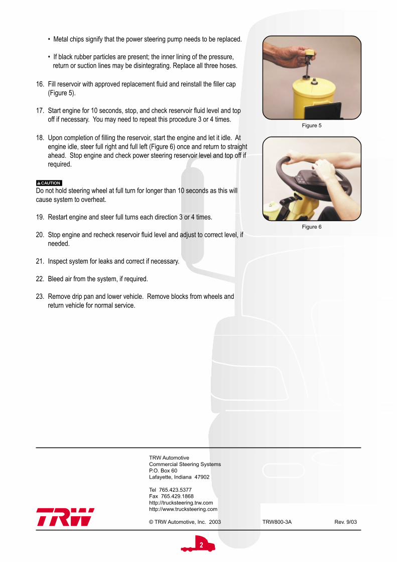
16. Fill reservoir with approved replacement fluid and reinstall the filler cap(Figure 5).
17. Start engine for 10 seconds, stop, and check reservoir fluid level and topoff if necessary. You may need to repeat this procedure 3 or 4 times.
18. Upon completion of filling the reservoir, start the engine and let it idle. Atengine idle, steer full right and full left (Figure 6) once and return to straightahead. Stop engine and check power steering reservoir level and top off ifrequired.
CAUTION
Do not hold steering wheel at full turn for longer than 10 seconds as this willcause system to overheat.
19. Restart engine and steer full turns each direction 3 or 4 times.
20. Stop engine and recheck reservoir fluid level and adjust to correct level, ifneeded.
21. Inspect system for leaks and correct if necessary.
22. Bleed air from the system, if required.
23. Remove drip pan and lower vehicle. Remove blocks from wheels andreturn vehicle for normal service.
Figure 6
Figure 5
TRW AutomotiveCommercial Steering SystemsP.O. Box 60Lafayette, Indiana 47902
Tel 765.423.5377Fax 765.429.1868http://trucksteering.trw.comhttp://www.trucksteering.com
© TRW Automotive, Inc. 2003 TRW800-3A Rev. 9/03

1
Air Bleeding the Steering System
Automatic Bleed Gears
1. Fill the reservoir.
2. Start the engine, let it run for 10 seconds - without steering, then shut it off.
3. Check the reservoir, and refill if the fluid level has dropped.
4. Repeat at least three times, checking and refilling the reservoir each time ifnecessary.
NOTE
Do not allow the fluid level to drop significantly or run out of the reservoir. Thismay induce air into the system.
5. Start the engine and let it idle for 2 minutes - without steering. Shut off theengine and check the fluid level in the reservoir. Refill if required.
6. Start the engine again. Steer the vehicle from full left to full right severaltimes. Automatic bleed systems should now be free from trapped air.
7. Finally, be sure to check the fluid level in the reservoir. Refill if necessarybefore returning the vehicle to service.
Gear Mounting Configurations
Visual Identification
When you air bleed a steering system, you are simply allowing air trapped in the cavities of the steering gear to escape.As a general rule, if your steering gear is a “standard mount”, you should use the Automatic Bleed method. If your gear isan “inverted mount”, you will need to use the Manual Bleed method to purge the trapped air from the gear.
Auto Bleed Plug Location
Standard Inverted
Auto Bleed Plug Styles
Hex Head Torx Head

2
TRW AutomotiveCommercial Steering SystemsP.O. Box 60Lafayette, Indiana 47902
Tel 765.423.5377Fax 765.429.1868http://trucksteering.trw.comhttp://www.trucksteering.com
© TRW Automotive, Inc. 2003 TRW800-3B Rev. 9/03
Manual Bleed Gears
1. Fill the reservoir.
2. Start the engine, let it run for 10 seconds - without steering, then shut it off.
3. Check the reservoir, and refill if the fluid level has dropped.
4. Repeat this process at least three times, checking and refilling the reser-voir each time if necessary.
NOTE
Do not allow the fluid level to drop significantly or run out of the reservoir. Thismay induce air into the system.
5. Start the engine and let it idle for 2 minutes - without steering. Shut off theengine and check the fluid level in the reservoir. Refill if required.
6. Start the engine again. Steer the vehicle from full left to full right severaltimes.
7. Again, check the fluid level in the reservoir.
8. With the engine idling, steer from full left turn to full right turn several times.Stop steering with the wheels pointed straight ahead and loosen themanual bleed screw 2-3 turns.
9. Allow air and aerated fluid to “bleed out” until fluid appears withoutbubbles.
10. Close the bleed screw, refill the reservoir if required.
11. Repeat this process three or four times until all the air is discharged.Torque manual bleed screw to 45 in•lb.
CAUTION
Do not turn steering wheel with bleed screw loosened.
Figure 1
Manual Bleed Screw Location
Figure 1
Manual Bleed Screw Style
5/16” Hexagon Screw

1
Poppets
What are Poppets?
Poppets are pressure unloading valves, inside the rack piston, that “relieve” just before a full turn is made in each direc-tion. When poppets are set or reset correctly, system pressure will be reduced before the axle stop bolt contacts the axlestop in both directions.
Poppet Resetting Criteria
Poppets on TRW steering gears do not have to be reset, unless the vehicle has been modified in such a way thatwheelcut for the vehicle is decreased.
If the gear has a fixed stop bolt and you are decreasing the vehicle’s wheelcut, you will need a new poppet adjustingscrew and jam nut. If wheelcut is being increased, the poppets will reset automatically. In this case, refer to the PoppetSetting procedure.
Examples of modifications that require poppet resetting include:
• Changing to larger tires• Reducing wheelcut for any reason• Steer axle U-bolts were bent or broken• If the pitman arm was mistimed and was retimed• Axle stop bolts were damaged and have been replaced• Or when the steering gear has been mounted on a different vehicle.
Use the POPPET RESETTING PROCEDURES only if you made a modification to the vehicle as outlined in the list above.
Steering Gear - Section View
1. Fixed Stop Bolt2. Lower Poppet3. Lower Poppet Seat4. Lower Poppet Sleeve5. Spring6. Push Tube7. Upper Poppet Sleeve8. Upper Poppet Seat9. Upper Poppet10. Valve Housing11. Input Shaft12. Valve13. Recirculating Steel Balls14. Rack Piston15. Worm Screw16. Pitman Arm17. Timing Marks18. Sector Shaft19. Housing
1 32 4 5 6 7 8 9 10
13
111215
14
18
17
16
19

2
System Identification
Before resetting poppets on a steering gear, you mustidentify the type of system with which you are working.
For single gear and a gear with linear assist cylinders,use the Single Gear Poppet Resetting procedure.
On a dual gear system, you must determine whether thesystem has either mirror image gears or reversed imagegears. The procedures are slightly different for each typeof system, so use the following criteria to identify whichmethod applies to your application.
1. Park the vehicle with the wheels turned all the way tothe axle stop in either direction. Turn the vehicle off.
2. Look at the output shaft timing mark nearest thehousing piston bore on the main gear. Is this markpointing toward the poppet screw or away from it?
3. Now check the output shaft timing mark nearest thehousing piston bore on the rotary cylinder. Does itpoint toward the poppet screw or away from it?
Use the MIRROR SYSTEM procedure if the timing markspoint to opposite ends of the gears.
Use the REVERSE SYSTEM procedure if both timingmarks point toward the poppet screws or both pointtoward the end opposite the poppet screws.
Initial Poppet Setting Procedure
For this procedure to work correctly, you must have 1) A new or remanufactured gear received from TRW or your vehiclemanufacturer’s aftermarket system, or 2) a used gear on which poppet seats have been replaced or reset during geardisassembly and assembly procedures. Also, a fixed stop bolt or a poppet adjusting screw must be part of the steeringgear assembly.
To set the poppets on a new or remanufactured steering gear, follow these simple steps.
1. Make sure the axle stop bolts are set to vehicle manufacturer’s wheelcut or clearance specifications.
2. Raise the front end so the steer axle tires are off the ground.
3. Start the engine and let it idle.
4. Steer the vehicle in in one direction, until you contact the axle stop. Pull hard on the steering wheel.
5. Now, steer the vehicle in the opposite direction until you contact the axle stop. Again, pull hard on the steering wheel.
6. Turn the vehicle off.
Rotary Cylinder Main Gear
Poppet Screws
Rotary Cylinder Main Gear
Poppet Screws
Reverse System
Mirror System

3
Single Gear Poppet Resetting Procedure
1. Set the axle stops to vehicle manufacturer’s wheelcut or clearancespecifications.
2. Make sure the engine is off and the road wheels are in the straight aheadposition.
3. Remove and discard the poppet fixed stop bolt and washer (Figure 1, ifequipped) from the lower end of the housing. If the gear has a poppetadjusting screw and jam nut that need to be replaced, remove and discardthem at this point also.
4. If a new poppet adjusting screw and nut are being used, turn the screwinto the non-sealing end of the jam nut until the Allen drive end of thescrew is flush with the nut (Figure 2).
Be sure the Allen drive end of the screw is not below the face of the nut.Failing to keep it flush with the face of the nut will cause the poppet seat flangeto break later on during this procedure.
5. If the adjusting screw is already part of the steering gear (Figure 3), backthe nut off of the adjusting screw until it is flush with the Allen drive end ofthe adjusting screw.
6. Turn the new adjusting screw and jam nut into the housing until the nut isfirmly against the housing using an Allen wrench. Tighten the jam nutagainst the housing.
7. Refill the system reservoir with approved hydraulic fluid.
Do not mix fluid types. Mixing of transmission fluid, motor oil, or other hydraulicfluids will cause seals to deteriorate faster.
8. Place a jack under the center of the front axle and raise the front end of thevehicle so the steer axle tires are off the ground.
9. Start the engine and let it run at idle speed.
10. Note which output shaft timing mark is nearest the housing piston bore.
11. Turn the steering wheel in the direction that makes this timing mark movetoward the adjusting screw you just installed (Figure 4). Turn in thisdirection until axle stop contact is made.
12. Pull hard (Figure 5) on the steering wheel (put up to 40 lb rim pull on a 20"dia. steering wheel) after the axle stop is contacted.
Do not hold the steering wheel at full turn for more than 10 seconds at a time;the heat build-up at pump relief pressure may damage system components.
Figure 2
Figure 1
Figure 3
Figure 4
Figure 5

4
13. Turn the steering wheel in the opposite direction (end of timing mark awayfrom adjusting screw, Figure 6) until the other axle stop is contacted.
14. Pull hard on the steering wheel.
15. Release the steering wheel and shut off the engine.
16. Loosen the jam nut and back out the adjusting screw until 1" is past the nut(Figure 7). Tighten the jam nut against the housing.
17. Start the engine and let it idle.
18. Turn the steering wheel, so that the timing mark on the output shaft pointstoward the adjusting screw, until axle stop contact is made.
19. Pull hard on the steering wheel and hold it in this position for no more than10 seconds at a time, then release to allow the system to cool.
20. Repeat this hold and release process while completing steps 21-22.
21. Loosen the jam nut and hold it in place with a wrench so it will not contactthe housing.
22. With steering wheel held at full turn, turn the adjusting screw in (clockwise)using finger-pressure only (do not use a ratchet), until the Allen wrenchstops (Figure 8). At this point, the adjusting screw has contacted thepoppet seat. Do not attempt to turn it in farther.
Pause the turning-in process each time the driver releases the steering wheel;continue turning the adjusting screw in only while the wheel is held at full turn.
23. Back off the adjusting screw 31/4 turns and tighten the jam nut. Torque thejam nut to 35 ft•lbs.
The poppets have now been reset. Lower the vehicle and remove the jack.
Be sure to check the reservoir and fill if required.
Do not remove the adjusting screw, it is now part of the steering gear assembly.
The length of the poppet adjusting screw beyond the nut may be different foreach vehicle, but must be no more than 11/16" for proper thread engagement(Figure 9).
Figure 7
Figure 6
Figure 9
Figure 8

5
Poppet Resetting - Mirror System
This resetting procedure will work in most cases with at least 13/4 hand-wheel-turns from each side of center. If you’remaking a large reduction in wheelcut and this procedure does not work, you may have to replace or internally reset thepoppets using the procedure described in the appropriate gear service manual.
1. Set the axle stops to vehicle manufacturer’s wheelcut or clearance specifications.
2. Make sure the engine is off and the road wheels are in straight ahead position.
3. Remove and discard the poppet fixed stop bolt and washer (if equipped) from the lower end of the housing on boththe main gear and the rotary cylinder. If either unit has a poppet adjusting screw and jam nut that need to be re-placed, remove and discard them at this point also.
If a new poppet adjusting screw and nut are being used, turn the screws into the non-sealing end of the jam nuts untilthe Allen drive end of the screw is flush with the nut.
Be sure the Allen drive end of the screw is not below the face of the nut. Failing to keep it flush with the face of the nut willcause the poppet seat flange to break later on during this procedure.
4. If the adjusting screw is already part of the main gear or rotary cylinder, back the nut off of the adjusting screw until itis flush with the Allen drive end of the adjusting screw.
5. Turn the new adjusting screw and jam nut (without rotating the jam nut on the screw) into the housing until the jamnut is firmly against the housing, on both the main gear and the rotary cylinder, using an Allen wrench. Tighten thejam nut against the housing.
6. Refill the system reservoir with approved hydraulic fluid.
Do not mix fluid types. Mixing of transmission fluid, motor oil, or other hydraulic fluids will cause seals to deterioratefaster.
7. Place a jack under the center of the front axle and raise the front end of the vehicle so the steer axle tires are off theground.
8. Start the engine and let it run at idle speed.
9. Note which output shaft timing mark is nearest the housing piston bore.
10. Turn the steering wheel in the direction that makes this timing mark move toward the adjusting screw you justinstalled on the main gear. Turn in this direction until axle stop contact is made.
11. Pull hard on the steering wheel (put 40 lbs. rim pull on a 20" dia. steering wheel) after the axle stop is contacted.
Do not hold the steering wheel at full turn for more than 10 seconds at a time; the heat build-up at pump relief pressuremay damage system components.
12. Turn the steering wheel in the opposite direction (end of timing mark points away from adjusting screw on the maingear) until the other axle stop is contacted.
13. Pull hard on the steering wheel.

6
14. Release the steering wheel and shut off the engine.
15. Loosen the jam nut and back out the adjusting screw, on both the main gear and the rotary cylinder, until 1" is pastthe nut. Tighten the jam nuts against the housings.
16. Start the engine and let it idle.
17. Turn the steering wheel, so that the timing mark on the main gear output shaft points toward the adjusting screw, untilaxle stop contact is made.
18. Pull hard on the steering wheel and hold it in this position for no more than 10 seconds at a time, then release toallow the system to cool.
19. Repeat this hold and release process while completing the following steps for both the main gear and rotary cylinderadjustments.
Pause the turning-in process each time the driver releases the steering wheel; continue turning the adjusting screw in onlywhile the wheel is held at full turn.
Main Gear Adjustment
1. With steering wheel held at full turn, loosen the jam nut on the main gear, and hold it in place with a wrench so it willnot contact the housing.
2. Turn the adjusting screw in (clockwise) using finger-pressure only (do not use a ratchet), until the Allen wrench stops.At this point, the adjusting screw has contacted the poppet seat. Do not attempt to turn it in farther.
3. Back off the adjusting screw 31/4 turns and tighten the jam nut. Torque the jam nut to 35 ft•lbs.
Rotary Cylinder Adjustment
1. Turn the steering wheel in the opposite direction, so that the timing mark on the main gear output shaft points awayfrom the adjusting screw, until axle stop contact is made.
2. With steering wheel held at full turn, loosen the jam nut on the rotary cylinder and hold it in place with a wrench so itwill not contact the housing.
3. Turn the adjusting screw in (clockwise) using finger-pressure only (do not use a ratchet), until the Allen wrench stops.At this point, the adjusting screw has contacted the poppet seat. Do not attempt to turn it in farther.
4. Back off the adjusting screw 31/4 turns and tighten the jam nut. Torque the jam nut to 35 ft•lbs.
5. The poppets on both the main gear and rotary cylinder have now been reset. Lower the vehicle . Check the fluidlevel in the reservoir and fill if required.
Do not remove the poppet adjusting screws, they are now part of the main gear and rotary cylinder assemblies.
The length of the poppet adjusting screw beyond the nut may be different for each vehicle, but must be no more than 11/16"for proper thread engagement.

7
Poppet Resetting - Reverse System
This resetting procedure will work in most cases with at least 13/4 hand-wheel-turns from each side of center. If you’remaking a large reduction in wheelcut and this procedure does not work, you may have to replace or internally reset thepoppets using the procedure described in the appropriate gear service manual.
1. Set the axle stops to vehicle manufacturer’s wheelcut or clearance specifications.
2. Make sure the engine is off and the road wheels are in straight ahead position.
3. Remove and discard the poppet fixed stop bolt and washer (if equipped) from the lower end of the housing on boththe main gear and the rotary cylinder. If either unit has a poppet adjusting screw and jam nut that need to be re-placed, remove and discard them at this point also.
If a new poppet adjusting screw and nut are being used, turn the screws into the non-sealing end of the jam nuts untilthe Allen drive end of the screw is flush with the nut.
Be sure the Allen drive end of the screw is not below the face of the nut. Failing to keep it flush with the face of the nut willcause the poppet seat flange to break later on during this procedure.
4. If the adjusting screw is already part of the main gear or rotary cylinder, back the nut off of the adjusting screw until itis flush with the Allen drive end of the adjusting screw.
5. Turn the new adjusting screw and jam nut (without rotating the jam nut on the screw) into the housing until the jamnut is firmly against the housing, on both the main gear and the rotary cylinder, using an Allen wrench. Tighten thejam nut against the housing.
6. Refill the system reservoir with approved hydraulic fluid.
Do not mix fluid types. Mixing of transmission fluid, motor oil, or other hydraulic fluids will cause seals to deterioratefaster.
7. Place a jack under the center of the front axle and raise the front end of the vehicle so the steer axle tires are off theground.
8. Start the engine and let it run at idle speed.
9. Note which output shaft timing mark is nearest the housing piston bore.
10. Turn the steering wheel in the direction that makes this timing mark move toward the adjusting screws you justinstalled on both the main gear and the rotary cylinder. Turn in this direction until axle stop contact is made.
11. Pull hard on the steering wheel (put 40 lbs. rim pull on a 20" dia. steering wheel) after the axle stop is contacted.
Do not hold the steering wheel at full turn for more than 10 seconds at a time; the heat build-up at pump relief pressuremay damage system components.
12. Turn the steering wheel in the opposite direction (end of timing mark points away from adjusting screw) until the otheraxle stop is contacted.
13. Pull hard on the steering wheel.
14. Release the steering wheel and shut off the engine.

8
TRW AutomotiveCommercial Steering SystemsP.O. Box 60Lafayette, Indiana 47902
Tel 765.423.5377Fax 765.429.1868http://trucksteering.trw.comhttp://www.trucksteering.com
© TRW Automotive, Inc. 2003 TRW800-4 Rev. 9/03
15. Loosen the jam nut and back out the adjusting screw until 1" is past the nut on both the main gear and the rotarycylinder. Tighten the jam nut against both housings.
16. Start the engine and let it idle.
17. Turn the steering wheel, so that the timing mark on the output shaft points toward the adjusting screw, until axle stopcontact is made.
18. Pull hard on the steering wheel and hold it in this position for no more than 10 seconds at a time, then release toallow the system to cool.
19. Repeat this hold and release process while completing the following steps. First on the main gear, then on the rotarycylinder.
Pause the turning-in process each time the driver releases the steering wheel; continue turning the adjusting screw in onlywhile the wheel is held at full turn.
Main Gear Adjustment
1. With steering wheel held at full turn, loosen the jam nut on the main gear, and hold it in place with a wrench so it willnot contact the housing.
2. Turn the adjusting screw in (clockwise) using finger-pressure only (do not use a ratchet), until the Allen wrench stops.At this point, the adjusting screw has contacted the poppet seat. Do not attempt to turn it in farther.
3. Back off the adjusting screw 31/4 turns and tighten the jam nut. Torque the jam nut to 35 ft•lbs.
Rotary Cylinder Adjustment
1. With steering wheel held at full turn, loosen the jam nut on the rotary cylinder and hold it in place with a wrench so itwill not contact the housing.
2. Turn the adjusting screw in (clockwise) using finger-pressure only (do not use a ratchet), until the Allen wrench stops.At this point, the adjusting screw has contacted the poppet seat. Do not attempt to turn it in farther.
3. Back off the adjusting screw 31/4 turns and tighten the jam nut. Torque the jam nut to 35 ft•lbs.
4. The poppets on both the main gear and rotary cylinder have now been reset. Lower the vehicle . Check the fluidlevel in the reservoir and fill if required.
Do not remove the poppet adjusting screws, they are now part of the main gear and rotary cylinder assemblies.
The length of the poppet adjusting screw beyond the nut may be different for each vehicle, but must be no more than 11/16"for proper thread engagement.

1
Linkage Inspection, Maintenance,Replacement, and AdjustmentInspection Criteria
First by lightly rocking the steering wheel, observe any looseness in the twomating tapers, or any movement of the stud nut. Looseness in either placerequires further inspection.
If either of the mating tapered parts show distortion or wear, both parts must bereplaced.
Second, make sure the wheels are straight ahead, the truck engine is turnedoff, and no force is being exerted on the linkage by the steering gear. To checkthe soundness of the joint, just use your hand to push and pull the tie rod end inand out in the direction of the ball stud axix (see illustration).
For inspection purposes, the link must be held without twisting, and with hand-pressure only (approximately 100 lbs), measured with a scale for in and outmotion on the ball stud axis. If the in and out motion on the stud’s axis mea-sures over 1/8" or 3 mm with hand pressure only, then the vehicle should betaken out of service.
If it moves, but measures less than 1/8" (3 mm) it should be replaced at thenearest practical service center. Any movement less than 1/8" (3 mm) is strictlya maintenance issue for the vehicle.
Do not use a wrench or other object to obtain more leverage. Applying leverage to any linkage can cause movementregardless of whether or not the linkage needs to be replaced. Applying leverage can also damage the linkage
Don’t apply steering gear power to the joint to test for a worn tie rod end; that produces normal movement, and thatmovement is not an indicator of wear.
Maintenance Checklist
Each time the tie rod ends are lubricated you should also visually inspect for:
• Cracks, breaks or bends in the linkage components.
• Check for broken clamps and gouges on tubes from rubbing parts.
• Check for missing or damaged grease fittings. Some tie rod ends are not equipped with grease fittings from the
factory. But if one is supposed to be there and it is not, the missing fitting must be replaced.
• Check for any form of tearing or improper sealing on the seal. Also check for wear on the socket throat.
• Check all tie rod end connections for missing cotter pins.
Tie Rod End - Section View
Inspect for movement alongvertical axis only.

2
Figure 2
Figure 1
Figure 3
Figure 4
Tie Rod End Replacement
If the lash is originating from the tie rod end, it will need to be replaced. If thelash is in the tapered stud connection between the tie rod end and its matingpart, both the tie rod end and the mating part must be replaced to recreate aproper fit between the two.
1. Loosen the clamp or jam nut on the tie rod end (Figure 1).
2. Disconnect the tie rod end from the mating component.
3. Unscrew the tie rod end from the tube (Figure 2). Use a pipe wrench ifnecessary, being careful not to deform the tube.
4. Screw the new tie rod end into the tube (Figure 3). Tie rod end threadsmust be visible the entire length of the cross tube slot. The tie rod end isto be engaged at least one thread deeper than the end of the cross tubeslot.
5. Refer to the adjustment and centering procedures, for the type of assemblyyour are working on, covered in this document.
6. Torque the clamp nut or jam nut (Figure 5) to the vehicle manufacturer’sspecifications.
Figure 5

3
Figure 2
Figure 1
Figure 3
Figure 4
Figure 5
Draglink– One End Adjustable
1. Position the road wheels straight ahead.
2. Disconnect the draglink at the pitman arm using the appropriate tool.
3. Make sure the steering gear is on center by aligning the timing marks onthe housing and output shaft.
4. Loosen the clamp on the draglink.
5. Adjust the draglink length to fit the holes on the pitman arm and the axlesteer arm.
6. Grasp the long side of the draglink with both hands (Figure 1). Rotate itaway from you as far as it will go, then toward you as far as it will go.Center between these two points.
7. Hold the long side in place. Grasp the tie rod end (Figure 2) and rotate ittoward you and away from you as far as you. Center the tie rod endbetween these two points.
8. With both ends centered, tighten the clamp, and torque (Figure 3) tovehicle manufacturer’s specifications.
WARNING
If the clamp is tack-welded (Figure 4), don’t remove the tack weld. If removed,clamping force will not be enough to keep the tie rod end threads stationary.Loss of steering control will result. If the tack welded end requires replace-ment, the entire assembly needs to be replaced.
NOTE
If the clamp is free-to-rotate (Figure 5) it can be tightened in any positionproperly, as long as there is enough clearance from other parts.
9. Lubricate both tie rod ends (unless they are non-greaseable ends) untilyou can see clean grease purging out of the seal. Use #2 NLGI Grease.
NOTE
This purge is necessary to ensure contaminants are removed from socketassemblies.

4
Draglink– Two End Adjustable
1. Position the road wheels straight ahead.
2. Loosen the clamps on the both ends of the draglink.
3. Rotate the center tube of the draglink (Figure 1) until the steering gear ison center (housing and output shaft timing marks aligned).
4. Tighten the clamps and torque (Figure 2) to manufacturer’s specifications.
WARNING
If the clamp is tack-welded (Figure 3), don’t remove the tack weld. If removed,clamping force will not be enough to keep the tie rod end threads stationary.Loss of steering control will result. If the tack welded end requires replace-ment, the entire assembly needs to be replaced.
NOTE
If the clamp is free-to-rotate (Figure 4) it can be tightened in any positionproperly, as long as there is enough clearance from other parts.
5. Lubricate both tie rod ends (unless they are non-greaseable ends) untilyou can see clean grease purging out of the seal. Use #2 NLGI Grease.
NOTE
This purge is necessary to ensure contaminants are removed from socketassemblies.
Figure 2
Figure 1
Figure 3
Figure 4

5
Tie Rod Tube Assembly– One End Adjustable
1. Position the road wheels straight ahead.
2. Raise the front end of the vehicle so the steer axle tires are off the ground.
3. Loosen the clamp on the tie rod tube.
4. Turn the hex adjuster until the toe is correct.
WARNING
Do not adjust the tie rod end to a position where you can see the end of the tierod end threads through the slot in the tube. If the socket threaded end isvisible, corrosion may occur in the tube and weaken the components.
5. Grasp the long side of the tie rod with both hands (Figure 1). Rotate itaway from you as far as it will go, then toward you as far as it will go.Center the tie rod between these two points.
6. Hold the long side in place. Grasp the tie rod end (Figure 2) and rotate ittoward you and away from you as far as you can. Center the tie rod endbetween these two points.
7. With both ends centered, tighten the clamp, and torque (Figure 3) tovehicle manufacturer’s specifications.
WARNING
If the clamp is tack-welded (Figure 4), don’t remove the tack weld. If removed,clamping force will not be enough to keep the tie rod end threads stationary.Loss of steering control will result. If the tack welded end requires replace-ment, the entire assembly needs to be replaced.
NOTE
If the clamp is free-to-rotate (Figure 5) it can be tightened in any positionproperly, as long as there is enough clearance from other parts.
8. Lubricate both tie rod ends (unless they are non-greaseable ends) untilyou can see clean grease purging out of the seal. Use #2 NLGI Grease.
NOTE
This purge is necessary to ensure contaminants are removed from socketassemblies.
Figure 2
Figure 1
Figure 3
Figure 1
Figure 1

6
Tie Rod Tube Assembly– Two End Adjustable
1. Position road wheels straight ahead.
2. Loosen the clamps on both ends of the tie rod tube.
3. Rotate the center tube of the tie rod (Figure 1) until achieve proper toe-inmeasurements on the front wheels.
4. Tighten the clamps and torque (Figure 2) to manufacturer’s specifications.
WARNING
If the clamp is tack-welded (Figure 3), don’t remove the tack weld. If removed,clamping force will not be enough to keep the tie rod end threads stationary.Loss of steering control will result. If the tack welded end requires replace-ment, the entire assembly needs to be replaced.
NOTE
If the clamp is free-to-rotate (Figure 4) it can be tightened in any positionproperly, as long as there is enough clearance from other parts.
5. Lubricate both tie rod ends (unless they are non-greaseable ends) untilyou can see clean grease purging out of the seal. Use #2 NLGI Grease.
NOTE
This purge is necessary to ensure contaminants are removed from socketassemblies.
Figure 1
Figure 2
Figure 3
Figure 4

7
Figure 1
Drop Center Tie Rod Tube Assembly–One End Adjustable
1. Position road wheels straight ahead.
2. Place a jack under the center of the front axle. Raise up the front end ofthe vehicle so the steer axle tires are off the ground.
3. Loosen the clamp on the tie rod tube.
Disconnect the tie rod from the tie rod arm at the adjustable end.
4. Adjust the socket in one-full-turn increments (Figure 1). Reinstall thesocket end, tighten (do not torque) the fastener after each full turn.
5. Check the toe-in measurement after each full turn adjustment. Repeat asnecessary until the toe is correct.
6. Grasp the long side of the tie rod with both hands (Figure 2). Rotate itaway from you as far as it will go, then toward you as far as it will go.Center the tie rod between these two points.
7. Hold the long side in place. Grasp the tie rod end (Figure 3) and rotate ittoward you and away from you as far as you can. Center the tie rod endbetween these two points.
8. With both ends centered, tighten the clamp, and torque to vehiclemanufacturer’s specifications.
WARNING
If the clamp is tack-welded (Figure 4), don’t remove the tack weld. If removed,clamping force will not be enough to keep the tie rod end threads stationary.Loss of steering control will result. If the tack welded end requires replace-ment, the entire assembly needs to be replaced.
NOTE
If the clamp is free-to-rotate (Figure 5) it can be tightened in any positionproperly, as long as there is enough clearance from other parts.
9. Lubricate both tie rod ends (unless they are non-greaseable ends) untilyou can see clean grease purging out of the seal. Use #2 NLGI Grease.
NOTE
This purge is necessary to ensure contaminants are removed from socketassemblies.
Figure 2
Figure 4
Figure 5
Figure 3

8
TRW AutomotiveCommercial Steering SystemsP.O. Box 60Lafayette, Indiana 47902
Tel 765.423.5377Fax 765.429.1868http://trucksteering.trw.comhttp://www.trucksteering.com
© TRW Automotive, Inc. 2003 TRW800-5 Rev. 9/03
1
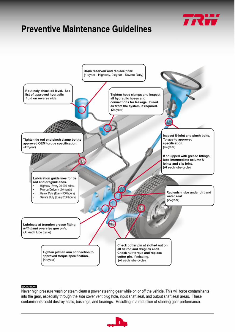
Lubrication guidelines for tierod and draglink ends.• Highway (Every 20,000 miles)• Pick-up/Delivery (2x/month)• Heavy Duty (Every 500 hours)• Severe Duty (Every 250 hours)
Tighten tie rod end pinch clamp bolt toapproved OEM torque specification.(4x/year)
Tighten pitman arm connection toapproved torque specification.(4x/year)
Check cotter pin at slotted nut onall tie rod and draglink ends.Check nut torque and replacecotter pin, if missing.(At each lube cycle)
Replenish lube under dirt andwater seal.(2x/year)
Inspect U-joint and pinch bolts.Torque to approvedspecification.(4x/year)
If equipped with grease fittings,lube intermediate column U-joints and slip joint.(At each lube cycle)
Drain reservoir and replace filter.(1x/year - Highway, 2x/year - Severe Duty)
Routinely check oil level. Seelist of approved hydraulicfluid on reverse side.
Tighten hose clamps and inspectall hydraulic hoses andconnections for leakage. Bleedair from the system, if required.(2x/year)
Lubricate at trunnion grease fittingwith hand operated gun only.(At each lube cycle)
CAUTION
Never high pressure wash or steam clean a power steering gear while on or off the vehicle. This will force contaminantsinto the gear, especially through the side cover vent plug hole, input shaft seal, and output shaft seal areas. Thesecontaminants could destroy seals, bushings, and bearings. Resulting in a reduction of steering gear performance.
Preventive Maintenance Guidelines

2
TRW AutomotiveCommercial Steering SystemsP.O. Box 60Lafayette, Indiana 47902
Tel 765.423.5377Fax 765.429.1868http://trucksteering.trw.comhttp://www.trucksteering.com
© TRW Automotive, Inc. 2003 TRW800-6 Rev. 9/03
Approved Hydraulic Fluids
The type of fluid used in the power steering system is vital to extend both the life of the components and its seals. It isnecessary to utilize a steering system fluid that is specified and approved by the vehicle manufacturer and also complieswith TRW Commercial Steering Systems’ recommendation.
It is recommended that and fluid specification, outside of the compliant lubricant listed, be reviewed by TRW to ensure thecompatibility between the component and fluid type being used.
TRW recommends using one of the following fluids in the power steering system.
Automatic Transmission Fluid• Dexron II• Dexron III• Ford Mercon
NOTE
The steering system should be kept filled with one of the above fluids.
CAUTION
Completely flush the steering system when changing to another fluid. Replace the reservoir filter after flushing thesystem. Fill the system with one of the recommended fluids above, only. Do not mix fluid types. Any mixture or anyunapproved oil could lead to seal deterioration and leaks. A leak could ultimately cause the loss of fluid, which couldresult in a loss of power steering assist.
Be sure to bleed the air out of the system before putting the vehicle back into service.
Approved Grease
#2 NLGI extreme pressure, lithium based, moly filled, heavy duty grease.
NOTE
More specific procedures and intervals can be found in the vehicle manufacturers service manual. These procedures areTRW’s general guidelines for steering related preventive maintenance. Service manuals and technical bulletins are alsoavailable through our website.

1
Power Steering System Analyzer (PSSA)–Application and UseIntroductionThis booklet is intended to give the you, the technician, a better understanding of the power steering system analyzer.Primarily, how it works and how to properly use it to diagnose hydraulic power steering related issues. You should alsoknow that the use of the power steering system analyzer is required when completing many of the diagnostic tests foundin our Chart Your Way to Easy Steering - Diagnostics Service Manual. The test procedures were developed using TRWpower steering components. However, the operating principles of the power steering system analyzer can be applied toall commercial power steering systems.
The goal of this booklet is to take you step-by-step throught each of the test procedures which require the use of thepower steering system analyzer. This will then assist you in locating the root cause of any hydraulic steering relatedcomplaint and provide you with necessary test results when calling TRW.
WARNING
While performing these tests, TRW advises that you take necessary precautionswhen working with internal vehicle components and hot hydraulic fluid. Be sure to take special care to protect yourself,and those around you, while performing a diagnostic test.
CAUTION
Do not attempt to diagnose a hydraulic steering related problem without using a power steering system analyzer. You willnot be able to properly determine the correct information needed to analyze and diagnose the steering system.
This booklet will show you how to properly install the power steering system analyzer into the power steering system anduse it to get measured results for the following tests; Power Steering Pump, Pump Flow Control Response, Poppet TripPressure, and Internal Leakage.
Be sure to record your results in the tables (Page 6) and be prepared to provide this information when calling to talk withyour TRW Technical Service Representatives.
Installing the Power Steering System Analyzer
Some Chart Your Way diagnostic test procedures require a power steeringsystem analyzer which is a combination flow meter, pressure gauge and loadvalve all in one. The system analyzer lets you measure flow and pressureand apply a load to the pump through the steering systems hydraulic lines.
Depending on the model of gauge being used, you may see an arrow showingthe direction of the oil flow. This will assist you in making sure the flow meteris properly installed in the system. A load valve, located near the gauge, isused to either restrict or open the flow of oil to the system.
The gauge has a SAE/Metric scale to read the flow of oil in either GPM (U.S.gallons per minute) or LPM (liters per minute). The system pressure ismeasured in either PSI (U.S. pounds per square inch) or kg /cm2 (kilogramsper centimeter squared).
The power steering system analyzer is installed between the power steeringpump and the steering gear. Connect the valve end of the power steeringsystem analyzer to the steering gear's pressure port and the other end to thepump's pressure port.

2
Power Steering Pump Test
This section will instruct you on how to measure pump flow and system pressure. Be sure to follow the lines to make surethat they are hooked up correctly before attempting to perform any tests.
Verify engine idle speed per original equipment manufacturers specifications.
1. Install the power steering system analyzer in the pressure line with load valve fully open. Recheck and adjust thefluid level, if required. Install a temperature gauge in the reservoir and begin the test with the fluid temperaturebetween 125-135° F (52-57° C).
2. Run the engine at idle. Measure and record the flow and pressure readings (Table A).
CAUTION
When closing the power steering system analyzer load valve, do so slowly and keep an eye on the pressure gauge. Donot allow the system to exceed 3000 psi or (207 bar) for safety of personnel and to prevent damage to the vehicle.
CAUTION
Do not keep the load valve closed for more than 5 seconds at a time because damage to the system may result fromexcessive heat build-up.
3. With the engine at idel, adjust the load valve to show 1000 PSI on the gauge. Measure and record the flow andpressure readings (Table A).
4. Now with the load valve fully open, increase the engine speed to 1500 RPM, measure and record the flow andpressure readings (Table A).
5. With the engine speed at 1500 RPM, adjust the load valve to show 1000 PSI on the gauge. Measure and record theflow and pressure readings (Table A).
6. Determine the recommended flow range and maximum allowable system pressure for the steering system being usedby referring to your Original Equipment Manufacturer's service manual for your application.
7. Compare the minimum and maximum flows, and the relief pressure you measured, to gear and pump specificationsas shown in your service manuals
8. If the minimum measured pump flow is less than the minimum recommended flow for the steering gear used; thepump may not be putting out enough flow for an adequate steering speed. If the maximum system pressure is lowerthan that specified for the pump, it may not be developing enough pressure to steer the vehicle. If either case exists,the pump may need to be repaired or replaced.
NOTE
When hydraulic tests are completed and hoses are reconnected, check the fluid level and bleed the air from the hydraulicsystem using the procedures outlined in the appropriate steering gear service manual.

3
Pump Flow Control Response Test
This section will instruct you on how to determine proper pump flow control response. Be sure to follow the lines to makesure that they are hooked up correctly before attempting to perform any tests.
1. Install the power steering system analyzer in the pressure line with load valve fully open. Recheck and adjust thefluid level, if required. Install a temperature gauge in the reservoir and begin the test with the fluid temperaturebetween 125-135° F (52-57° C).
CAUTION
If the system temperature goes over 250° F (121° C), or 150° F (66° C) above the surrounding temperature at any timeduring the test, stop the test. This temperature level is considered extreme and steering system performance and life willbe seriously affected. Damage to hoses, seals, and other components may result if operated at extreme temperature. Ifthe steering system is operating above the recommended temperatures, the heat problem may be the root cause of thecomplaint.
CAUTION
When closing the power steering system analyzer load valve, do so slowly and keep an eye on the pressure gauge. Donot allow the system to exceed 3000 psi or (207 bar) for safety of personnel and to prevent damage to the vehicle.
CAUTION
Do not keep the load valve closed for more than 5 seconds at a time because damage to the system may result fromexcessive heat build-up.
2. With the engine at idle, note the flow rate. Fully close the load valve until the flow drops to zero. Quickly open the loadvalve observing the flow meter. The flow rate must instantly return to the reading you have already noted.
3. With the load valve open run the engine to 1500 RPM and note the flow rate. Fully close the load valve until the flowdrops to zero. Quickly open the load valve observing the flow meter. The flow rate must instantly return to the readingyou have already noted.
4. Conduct this pump response test three times at idle and three times at 1500 RPM. Record your results (Table B). Ifthe flow rate does not return immediately, the pump is malfunctioning, which can result in a momentary loss of powerassist.
NOTE
When hydraulic tests are completed and hoses are reconnected, check the fluid level and bleed the air from the hydraulicsystem using the procedures outlined in the appropriate steering gear service manual.

4
Poppet Trip Pressure Test
This section will instruct you on how to verify poppet trip pressure. Be sure to follow the lines to make sure that they arehooked up correctly before attempting to perform any tests.
1. Install the power steering system analyzer in the pressure line with load valve fully open. Recheck and adjust thefluid level, if required. Install a temperature gauge in the reservoir and begin the test with the fluid temperaturebetween 125-135° F (52-57° C).
2. Increase engine speed to 1500 RPM.
3. Steer the vehicle into a full right turn. Then, record the poppet trip pressure (Table C) shown on the power steeringsystem analyzer pressure gauge.
4. Now, steer the vehicle into a full left turn, and again, record the poppet trip pressure (Table C) shown on the powersteering system analyzer pressure gauge.
Each recorded value should be at least 200-400 PSI below pump relief test value previously noted in Table A. If you donot meet this criteria, poppets should be reset, using the procedure outlined in the appropriate steering gear manual.When complete, make sure to recheck the vehicle to make sure it is operating properly.
NOTE
When hydraulic tests are completed and hoses are reconnected, check the fluid level and bleed the air from the hydraulicsystem using the procedures outlined in the appropriate steering gear service manual.
Internal Leakage Test
Finally, you will be instructed on how to measure internal leakage for both a single gear and dual gear system. Be sure tofollow the lines to make sure that they are hooked up correctly before attempting perform any tests.
WARNING
This test can be dangerous if not performed correctly. Keep your fingers clear of the axle stops and spacer block duringthis test. Make sure that the spacer block contacts the axle stop squarely. Contact that is not square could break the axlestops or dangerously throw or eject the spacer block.
1. Install the power steering system analyzer in the pressure line with load valve fully open. Recheck and adjust thefluid level, if required. Install a temperature gauge in the reservoir and begin the test with the fluid temperaturebetween 125-135° F (52-57° C).
2. To test the steering gear for internal leakage, you must first prevent operation of the gear’s internal unloading(poppet) valves or relief valve (or both, in some gears). This will allow full pump relief pressure to develop. To preventoperation of the poppets, place an unhardened steel spacer block, at least one inch thick and long enough to keepyour fingers clear, between the axle stop at one wheel. If the steering gear is equipped with a relief valve, remove therelief valve cap, o-ring, and two piece relief valve from the steering gear valve housing. Install the relief valve plug,special tool number J37130, in its place to prevent operation of the steering gear relief valve.
NOTE
Be sure you reinstall the relief valve and valve cap with new o-ring, back into the gear after this test.
CAUTION
When running this test, do not hold the steering wheel in the full turn position for longer than 5 to 10 seconds at a time toavoid damaging the pump.
3. Turn the steering wheel until the axle stops bottom on the spacer block.

5
Internal Leakage Test (Continued)
4. Apply 20 pounds of force to the rim of the steering wheel during this test to be sure that the steering gear controlvalve is fully closed. The pressure gauge should now read pump relief pressure (see Table A). Record the steeringgear internal leakage (Table D) on the flow meter.
5. Repeat this test for the opposite direction of turn.
6. If internal leakage is greater than 1 gallon per minute (3.8 liters per minute) and there is no auxiliary hydraulic linearor rotary cylinder in the system, repair or replace the gear.
If the internal leakage is greater than 2 gallons per minute (7.6 liters per minute), and there is an auxiliary hydraulic linearor hydraulic rotary cylinder in the system, controlled by the gear, isolate the auxiliary cylinder from the system by discon-necting the auxiliary cylinder hydraulic lines at the steering gear auxiliary ports. Plug the steering gear ports with suitablesteel or high pressure plugs or caps.
In the event that a rotary cylinder is used in the system, connect the disconnected lines together with a suitable unionfitting. In the case of a linear cylinder, first plug the disconnected lines and then disconnect the cylinder from steeringlinkage, making sure it will clear the steered axle
Repeat the internal leakage test and record your results in Table D. If the internal leakage is less than 1 gallon per minute(3.8 liters per minute), repair or replace the auxiliary cylinder. If the internal leakage is greater than 1 gallon per minute(3.8 liters per minute), repair or replace the gear.
NOTE
When hydraulic tests are completed and hoses are reconnected, check the fluid level and bleed the air from the hydraulicsystem using the procedures outlined in the appropriate steering gear service manual.

6
Test Results
FF GPM or LPM at:
Engine(RPM)F No LoadF 1000PSI
IdleF F
1500F F
Relief Pressure: PSI/BAR
PSI or BAR
Pump Relief #1 (1500 RPM)
Pump Relief #2 (1500 RPM)
Pump Relief #3 (1500 RPM)F F
PSI or BAR
Pump Relief #1 (Idle)
Pump Relief #2 (Idle)
Pump Relief #3 (Idle)
FF PSI or BAR
Full right hand turnFF F
Full left hand turn
FF GPM or LPM
Full right hand turnFF F
Full left hand turn
FF GPM or LPM
Full right hand turnFF F
Full left hand turn
Table A
Table B
Table C
Table D
Single Gear System Dual Gear System

7
1
2
5
3
6
8
4
7
1
2
5
11
10
9
3
6
8
4
7
1
2
1413
12
5
11
10
9
3
6
8
4
7
1
2
1413
12
5
11
10
9
3
6
8
4
7
PSSA Installations
Typical Steering System Single Gear System
Dual SystemSingle Gear, Linear Cylinder Assist
Dual SystemSingle Gear, Rotary Cylinder
Legend
1. Thermometer 5. Steering Gear 9. Load Valve 13. Auxilliary Line2. Supply Line 6. Return Line 10. Flow Meter 14. Assist Cylinder3. Pump 7. Reservoir Filter 11. Pressure Gauge Linear or Rotary4. Pressure Line 8. Reservoir 12. Auxilliary Line
8
TRW AutomotiveCommercial Steering SystemsP.O. Box 60Lafayette, Indiana 47902
Tel 765.423.5377Fax 765.429.1868http://trucksteering.trw.comhttp://www.trucksteering.com
© TRW Automotive, Inc. 2003 TRW800-7 Rev. 9/03