stm32f1 series safety manual - user manual · stm32f1 series safety manual um1814 user manual...
TRANSCRIPT
IntroductionThis document must be read along with the technical documentation such as reference manual(s) and datasheets for theSTM32F1 Series microcontroller devices, available on www.st.com.
It describes how to use the devices in the context of a safety-related system, specifying the user's responsibilities for installationand operation in order to reach the targeted safety integrity level. It also pertains to the X-CUBE-STL software product.
It provides the essential information pertaining to the applicable functional safety standards, which allows system designers toavoid going into unnecessary details.
The document is written in compliance with IEC 61508, and it provides information relative to other functional safety standards.
The safety analysis in this manual takes into account the device variation in terms of memory size, available peripherals, andpackage.
STM32F1 Series safety manual
UM1814
User manual
UM1814 - Rev 5 - February 2020For further information contact your local STMicroelectronics sales office.
www.st.com
1 About this document
1.1 Purpose and scope
This document describes how to use Arm® Cortex®‑M3 -based STM32F1 Series microcontroller unit (MCU)devices (further also referred to as Device(s)) in the context of a safety‑related system, specifying the user'sresponsibilities for installation and operation, in order to reach the desired safety integrity level.It is useful to system designers willing to evaluate the safety of their solution embedding one or more Device(s).For terms used, refer to the glossary at the end of the document.
Note: Arm is a registered trademark of Arm Limited (or its subsidiaries) in the US and/or elsewhere.
1.2 Normative references
This document is written in compliance with the IEC 61508 international norm for functional safety of electrical,electronic and programmable electronic safety-related systems, version IEC 61508:1-7 © IEC:2010.The other functional safety standards considered in this manual are:• ISO 13849-1:2015, ISO13849-2:2012• IEC 62061:2005+AMD1:2012+AMD2:2015• IEC 61800-5-2:2016
The following table maps the document content with respect to the IEC 61508-2 Annex D requirements.
Table 1. Document sections versus IEC 61508-2 Annex D safety requirements
Safety requirement Section number
D2.1 a) a functional specification of the functions capable of being performed 3
D2.1 b) identification of the hardware and/or software configuration of the Compliant item 3.2
D2.1 c) constraints on the use of the Compliant item or assumptions on which analysis of the behavior orfailure rates of the item are based 3.2
D2.2 a) the failure modes of the Compliant item due to random hardware failures, that result in a failureof the function and that are not detected by diagnostics internal to the Compliant item;
3.7
D2.2 b) for every failure mode in a), an estimated failure rate;
D2.2 c) the failure modes of the Compliant item due to random hardware failures, that result in a failureof the function and that are detected by diagnostics internal to the Compliant item;
D2.2 d) the failure modes of the diagnostics, internal to the Compliant item due to random hardwarefailures, that result in a failure of the diagnostics to detect failures of the function;
D2.2 e) for every failure mode in c) and d), the estimated failure rate;
D2.2 f) for every failure mode in c) that is detected by diagnostics internal to the Compliant item, thediagnostic test interval; 3.2.2
D2.2 g) for every failure mode in c) the outputs of the Compliant item initiated by the internal diagnostics; 3.6
D2.2 h) any periodic proof test and/or maintenance requirements;
3.7D2.2 i) for those failure modes, in respect of a specified function, that are capable of being detected byexternal diagnostics, sufficient information must be provided to facilitate the development of an externaldiagnostics capability.
D2.2 j) the hardware fault tolerance;3D2.2 k) the classification as type A or type B of that part of the Compliant item that provides the function
(see 7.4.4.1.2 and 7.4.4.1.3);
UM1814About this document
UM1814 - Rev 5 page 2/91
1.3 Reference documents
[1] AN5370, Results of FMEA on STM32F1 Series microcontrollers.
[2] AN5098, Results of FMEDA on STM32F1 Series microcontroller.
UM1814Reference documents
UM1814 - Rev 5 page 3/91
2 Device development process
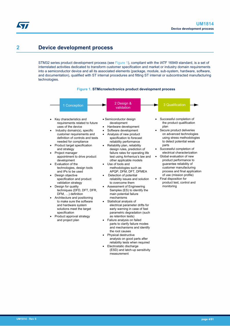
STM32 series product development process (see Figure 1), compliant with the IATF 16949 standard, is a set ofinterrelated activities dedicated to transform customer specification and market or industry domain requirementsinto a semiconductor device and all its associated elements (package, module, sub-system, hardware, software,and documentation), qualified with ST internal procedures and fitting ST internal or subcontracted manufacturingtechnologies.
Figure 1. STMicroelectronics product development process
· Key characteristics and requirements related to future uses of the device
· Industry domain(s), specific customer requirements and definition of controls and tests needed for compliance
· Product target specification and strategy
· Project manager appointment to drive product development
· Evaluation of the technologies, design tools and IPs to be used
· Design objective specification and product validation strategy
· Design for quality techniques (DFD, DFT, DFR, DFM, …) definition
· Architecture and positioning to make sure the software and hardware system solutions meet the target specification
· Product approval strategy and project plan
· Semiconductor design development
· Hardware development· Software development· Analysis of new product
specification to forecast reliability performance
· Reliability plan, reliability design rules, prediction of failure rates for operating life test using Arrhenius’s law and other applicable models
· Use of tools and methodologies such as APQP, DFM, DFT, DFMEA
· Detection of potential reliability issues and solution to overcome them
· Assessment of Engineering Samples (ES) to identify the main potential failure mechanisms
· Statistical analysis of electrical parameter drifts for early warning in case of fast parametric degradation (such as retention tests)
· Failure analysis on failed parts to clarify failure modes and mechanisms and identify the root causes
· Physical destructive analysis on good parts after reliability tests when required
· Electrostatic discharge (ESD) and latch-up sensitivity measurement
· Successful completion of the product qualification plan
· Secure product deliveries on advanced technologies using stress methodologies to detect potential weak parts
· Successful completion of electrical characterization
· Global evaluation of new product performance to guarantee reliability of customer manufacturing process and final application of use (mission profile)
· Final disposition for product test, control and monitoring
1 Conception 3 Qualification2 Design & validation
UM1814Device development process
UM1814 - Rev 5 page 4/91
3 Reference safety architecture
This section reports details of the STM32F1 Series safety architecture.
3.1 Safety architecture introduction
Device(s) analyzed in this document can be used as Compliant item(s) within different safety applications.The aim of this section is to identify such Compliant item(s), that is, to define the context of the analysis withrespect to a reference concept definition. The concept definition contains reference safety requirements, includingdesign aspects external to the defined Compliant item.As a consequence of Compliant item approach, the goal is to list the system-related information consideredduring the analysis, rather than to provide an exhaustive hazard and risk analysis of the system around thedevice. Such information includes, among others, application-related assumptions for danger factors, frequency offailures and diagnostic coverage already guaranteed by the application.
3.2 Compliant item
This section defines the Compliant item term and provides information on its usage in different safety architectureschemes.
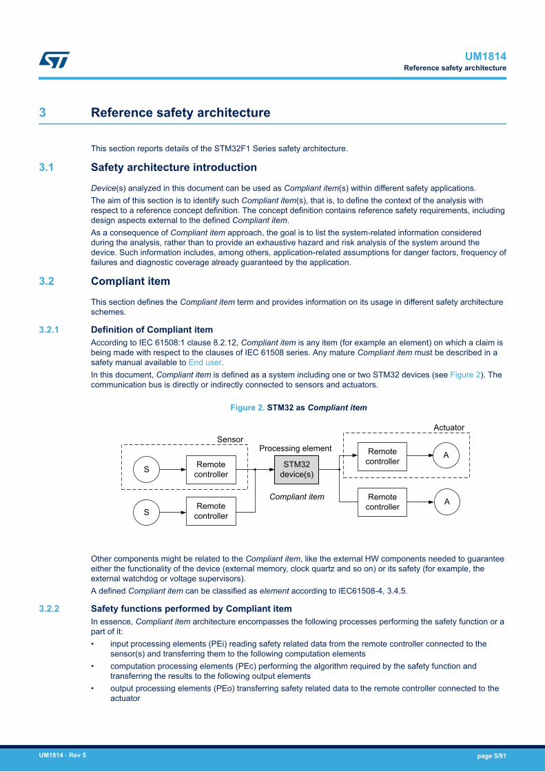
3.2.1 Definition of Compliant itemAccording to IEC 61508:1 clause 8.2.12, Compliant item is any item (for example an element) on which a claim isbeing made with respect to the clauses of IEC 61508 series. Any mature Compliant item must be described in asafety manual available to End user.In this document, Compliant item is defined as a system including one or two STM32 devices (see Figure 2). Thecommunication bus is directly or indirectly connected to sensors and actuators.
Figure 2. STM32 as Compliant item
Remote controller
Remote controller
Remote controller
Remote controller
SensorActuator
S
S
A
A
Processing element
Compliant item
STM32 device(s)
Other components might be related to the Compliant item, like the external HW components needed to guaranteeeither the functionality of the device (external memory, clock quartz and so on) or its safety (for example, theexternal watchdog or voltage supervisors).A defined Compliant item can be classified as element according to IEC61508-4, 3.4.5.
3.2.2 Safety functions performed by Compliant itemIn essence, Compliant item architecture encompasses the following processes performing the safety function or apart of it:• input processing elements (PEi) reading safety related data from the remote controller connected to the
sensor(s) and transferring them to the following computation elements• computation processing elements (PEc) performing the algorithm required by the safety function and
transferring the results to the following output elements• output processing elements (PEo) transferring safety related data to the remote controller connected to the
actuator
UM1814Reference safety architecture
UM1814 - Rev 5 page 5/91

• in 1oo2 architecture, potentially a further voting processing element (PEv)• the computation processing elements can be involved (to the extent depending to the target safety integrity)
in the implementation of local software-based diagnostic functions; this is represented by the block PEd• processes external to the Compliant item ensuring safety integrity, such as watchdog (WDTe) and voltage
monitors (VMONe)
The role of the PEv process and WDTe and VMONe external processes is clarified in the sections where theconditions of use (CoU) (definition of safety mechanism) are detailed:• WDTe: refer to External watchdog – CPU_SM_5 and Control flow monitoring in Application software –
CPU_SM_1,• VMONe: refer to Supply voltage monitoring – VSUP_SM_1 and System-level power supply management -
VSUP_SM_5.
In summary, the devices support the implementation of End user safety functions consisting of three operations:• safe acquisition of safety-related data from input peripheral(s)• safe execution of application software program and safe computation of related data• safe transfer of results or decisions to output peripheral(s)
Claims on the Compliant item and computation of safety metrics are done with respect to these three basicoperations.According to the definition for implemented safety functions, Compliant item (element) can be regarded as type B(as per IEC61508-2, 7.4.4.1.3 definition). Despite accurate, exhaustive and detailed failure analysis, Device hasto be considered as intrinsically complex. This implies its type B classification.Two main safety architectures are identified: 1oo1 (using one device) and 1oo2 (using two devices).
3.2.3 Reference safety architectures - 1oo11oo1 reference architecture (Figure 3) ensures safety integrity of Compliant item through combining deviceinternal processes (implemented safety mechanisms) with external processes WDTe and VMONe.1oo1 reference architecture targets safety integrity level (SIL) SIL2.
Figure 3. 1oo1 reference architecture
PEc Actuators
WDTe
Sensors
VMONe
PEoPEi
PEd
UM1814Compliant item
UM1814 - Rev 5 page 6/91

3.2.4 Reference safety architectures - 1oo21oo2 reference architecture (Figure 4) contains two separate channels, either implemented as 1oo1 referencearchitecture ensuring safety integrity of Compliant item through combining device internal processes(implemented safety mechanisms) with external processes WDTe and VMONe. The overall safety integrity is thenensured by the external voter PEv, which allows claiming hardware fault tolerance (HFT) equal to 1. Achievementof higher safety integrity levels as per IEC61508-2 Table 3 is therefore possible. Appropriate separation betweenthe two channels (including power supply separation) should be implemented in order to avoid huge impact ofcommon-cause failures (refer to Section 4.2 Analysis of dependent failures). However, β and βD parameterscomputation is required.1oo2 reference architecture targets SIL3.
Figure 4. 1oo2 reference architecture
ActuatorsSensors
VMONe
PEc PEoPEi
PEd
WDTeVMONe
PEv
PEc PEoPEi
PEd
WDTe
UM1814Compliant item
UM1814 - Rev 5 page 7/91
3.3 Safety analysis assumptions
This section collects all assumptions made during the safety analysis of the devices.
3.3.1 Safety requirement assumptionsThe concept specification, the hazard and risk analysis, the overall safety requirement specification and theconsequent allocation determine the requirements for Compliant item as further listed. ASR stands for assumedsafety requirements.
Caution: It is the End user’s responsibility to check the compliance of the final application with these assumptions.
ASR1: Compliant item can be used to implement four kinds of safety function modes of operation according topart 4,3.5.16:• a continuous mode (CM) or high-demand (HD) SIL3 safety function (CM3), or• a low-demand (LD) SIL3 safety function (LD3), or• a CM or HD SIL2 safety function (CM2), or• a LD SIL2 safety function (LD2).
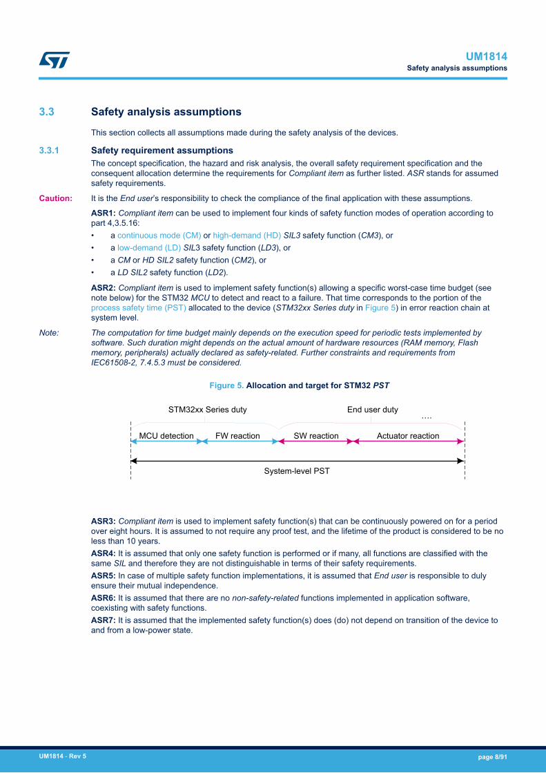
ASR2: Compliant item is used to implement safety function(s) allowing a specific worst-case time budget (seenote below) for the STM32 MCU to detect and react to a failure. That time corresponds to the portion of theprocess safety time (PST) allocated to the device (STM32xx Series duty in Figure 5) in error reaction chain atsystem level.
Note: The computation for time budget mainly depends on the execution speed for periodic tests implemented bysoftware. Such duration might depends on the actual amount of hardware resources (RAM memory, Flashmemory, peripherals) actually declared as safety-related. Further constraints and requirements fromIEC61508-2, 7.4.5.3 must be considered.
Figure 5. Allocation and target for STM32 PST
System-level PST
MCU detection FW reaction SW reaction Actuator reaction
STM32xx Series duty End user duty….
ASR3: Compliant item is used to implement safety function(s) that can be continuously powered on for a periodover eight hours. It is assumed to not require any proof test, and the lifetime of the product is considered to be noless than 10 years.ASR4: It is assumed that only one safety function is performed or if many, all functions are classified with thesame SIL and therefore they are not distinguishable in terms of their safety requirements.ASR5: In case of multiple safety function implementations, it is assumed that End user is responsible to dulyensure their mutual independence.ASR6: It is assumed that there are no non-safety-related functions implemented in application software,coexisting with safety functions.ASR7: It is assumed that the implemented safety function(s) does (do) not depend on transition of the device toand from a low-power state.
UM1814Safety analysis assumptions
UM1814 - Rev 5 page 8/91

ASR8: The local safe state of Compliant item is the one in which either:• SS1: the application software is informed by the presence of a fault and a reaction by the application
software itself is possible.• SS2: the application software cannot be informed by the presence of a fault or the application software is not
able to execute a reaction.
Note: End user must take into account that random hardware failures affecting the Device can compromise itsoperation (for example failure modes affecting the program counter prevent the correct execution of software).
The following table provides details on the SS1 and SS2 safe states.
Table 2. SS1 and SS2 safe state details
Safestate Condition Compliant item
actionSystem transition to safestate – 1oo1 architecture
System transition to safestate – 1oo2 architecture
SS1
The application software isinformed by the presence of afault and a reaction by theapplication software itself ispossible.
Fault reporting toapplicationsoftware
Application software drivesthe overall system in its safestate
Application software in one ofthe two channels drives theoverall system in its safe state
SS2
The application software cannotbe informed by the presence of afault or the application software isnot able to execute a reaction.
Reset signalissued by WDTe
WDTe drives the overallsystem in its safe state(“safe shut-down”) (1)
PEv drives the overall systemin its safe state
1. Safe state achievement intended here is compliant to Note on IEC 61508-2, 7.4.8.1
ASR9: It is assumed that the safe state defined at system level by End user is compatible with the assumed localsafe state (SS1, SS2) for Compliant item.ASR10: Compliant item is assumed to be analyzed according to routes 1H and 1S of IEC 61508-2.
Note: Refer to Section 3.5 Systematic safety integrity and Section 3.6 Hardware and software diagnostics.
ASR11: Compliant item is assumed to be regarded as type B, as per IEC 61508:2, 7.4.4.1.2.
3.4 Electrical specifications and environment limits
To ensure safety integrity, the user must operate the Device(s) within its (their) specified:• absolute maximum rating• capacity• operating conditions
For electrical specifications and environmental limits of Device(s), refer to its (their) technical documentation suchas datasheet(s) and reference manual(s) available on www.st.com.
3.5 Systematic safety integrity
According to the requirements of IEC 61508 -2, 7.4.2.2, the Route 1S is considered in the development ofDevice(s). As clearly authorized by IEC61508-2, 7.4.6.1, STM32 MCU products can be considered as standard,mass-produced electronic integrated devices, for which stringent development procedures, rigorous testing andextensive experience of use minimize the likelihood of design faults. However, ST internally assesses thecompliance of the Device development flow, through techniques and measures suggested in the IEC 61508-2Annex F. A safety case database (see Section 5 List of evidences) keeps evidences of the current compliancelevel to the norm.
UM1814Electrical specifications and environment limits
UM1814 - Rev 5 page 9/91

3.6 Hardware and software diagnostics
This section lists all the safety mechanisms (hardware, software and application-level) considered in the devicesafety analysis. It is expected that users are familiar with the architecture of the device, and that this document isused in conjunction with the related device datasheet, user manual and reference information. To avoidinconsistency and redundancy, this document does not report device functional details. In the followingdescriptions, the words safety mechanism, method, and requirement are used as synonyms.As the document provides information relative to the superset of peripherals available on the devices it covers(not all devices have all peripherals), users are supposed to disregard any recommendations not applicable totheir Device part number of interest.Information provided for a function or peripheral applies to all instances of such function or peripheral on Device.Refer to its reference manual or/and datasheet for related information.The implementation guidelines reported in the following section are for reference only. The safety verificationexecuted by ST during the device safety analysis and related diagnostic coverage figures reported in this manual(or related documents) are based on such guidelines. For clarity, safety mechanisms are grouped by Devicefunction.Information is organized in form of tables, one per safety mechanism, with the following fields:
SM CODE Unique safety mechanism code/identifier used also in FMEA document. Identifiers use the schememmm_SM_x where mmm is a 3- or 4-letter module (function, peripheral) short name, and x is anumber. It is possible that the numbering is not sequential (although usually incremental) and/or thatthe module short name is different from that used in other documents.
Description Short mnemonic description
Ownership ST : means that method is available on silicon.
End user: method must be implemented by End user through Application software modification,hardware solutions, or both.
Detailedimplementation
Detailed implementation sometimes including notes about the safety concept behind the introductionof the safety mechanism.
Error reporting Describes how the fault detection is reported to application software.
Fault detection time Time that the safety mechanism needs to detect the hardware failure.
Addressed faultmodel
Reports fault model(s) addressed by the diagnostic (permanent, transient, or both), and otherinformation:• If ranked for Fault avoidance: method contributes to lower the probability of occurrence of a
failure• If ranked for Systematic: method is conceived to mitigate systematic errors (bugs) in
application software design
Dependency onDevice configuration
Reports if safety mechanism implementation or characteristics change among different Device partnumbers.
Initialization Specific operation to be executed to activate the contribution of the safety mechanism
Periodicity Continuous : safety mechanism is active in continuous mode.
Periodic: safety mechanism is executed periodically(1).
On-demand: safety mechanism is activated in correspondence to a specified event (for instance,reception of a data message).
Startup: safety mechanism is supposed to be executed only at power-up or during off-linemaintenance periods.
Test for thediagnostic
Reports specific procedure (if any and recommended) to allow on-line tests of safety mechanismefficiency.
Multiple-faultprotection
Reports the safety mechanism(s) associated in order to correctly manage a multiple-fault scenario(refer to Section 4.1.3 Notes on multiple-fault scenario).
Recommendationsand known limitations
Additional recommendations or limitations (if any) not reported in other fields.
UM1814Hardware and software diagnostics
UM1814 - Rev 5 page 10/91

1. In CM systems, safety mechanism can be accounted for diagnostic coverage contribution only if it is executed at least onceper PST. For LD and HD systems, constraints from IEC61508-2, 7.4.5.3 must be applied.
3.6.1 Arm® Cortex®-M3 CPU
Table 3. CPU_SM_0
SM CODE CPU_SM_0
Description Periodical core self-test software for Arm® Cortex®-M3 CPU
Ownership End user or ST
Detailed implementation
The software test is built around well-known techniques already addressed by IEC 61508:7,A.3.2 (Self-test by software: walking bit one-channel). To reach the required values ofcoverage, the self-test software is specified by means of a detailed analysis of all the CPUfailure modes and related failure modes distribution
Error reporting Depends on implementation
Fault detection time Depends on implementation
Addressed fault model Permanent
Dependency on Device configuration None
Initialization None
Periodicity Periodic
Test for the diagnosticSelf-diagnostic capabilities can be embedded in the software, according the testimplementation design strategy chosen. The adoption of checksum protection on resultsvariables and defensive programming are recommended.
Multiple-fault protection CPU_SM_5: external watchdog
Recommendations and known limitations
This method is the main asset in STM32F1 Series safety concept. CPU integrity is a keyfactor because the defined diagnostics for MCU peripherals are to major part software-based.
Startup execution of this safety mechanism is recommended for multiple fault mitigations -refer to Section 4.1.3 Notes on multiple-fault scenario for details.
UM1814Hardware and software diagnostics
UM1814 - Rev 5 page 11/91

Table 4. CPU_SM_1
SM CODE CPU_SM_1
Description Control flow monitoring in Application software
Ownership End user
Detailed implementation
A significant part of the failure distribution of CPU core for permanent faults is related to failuremodes directly related to program counter loss of control or hang-up. Due to their intrinsicnature, such failure modes are not addressed by a standard software test method likeSM_CPU_0. Therefore it is necessary to implement a run-time control of the Applicationsoftware flow, in order to monitor and detect deviation from the expected behavior due to suchfaults. Linking this mechanism to watchdog firing assures that severe loss of control (or, in theworst case, a program counter hang-up) is detected.
The guidelines for the implementation of the method are the following:• Different internal states of the Application software are well documented and described
(the use of a dynamic state transition graph is encouraged).• Monitoring of the correctness of each transition between different states of the
Application software is implemented.• Transition through all expected states during the normal Application software program
loop is checked.• A function in charge of triggering the system watchdog is implemented in order to
constrain the triggering (preventing the issue of CPU reset by watchdog) also to thecorrect execution of the above-described method for program flow monitoring. The useof window feature available on internal window watchdog (WWDG) is recommended.
• The use of the independent watchdog (IWDG), or an external one, helps to implement amore robust control flow mechanism fed by a different clock source.
In any case, safety metrics do not depend on the kind of watchdog in use (the adoption ofindependent or external watchdog contributes to the mitigation of dependent failures, seeSection 4.2.2 Clock)
Error reporting Depends on implementation
Fault detection time Depends on implementation. Higher value is fixed by watchdog timeout interval.
Addressed fault model Permanent and transient
Dependency on Device configuration None
Initialization Depends on implementation
Periodicity Continuous
Test for the diagnostic NA
Multiple-fault protection CPU_SM_0: periodical core self-test software
Recommendations and known limitations -
UM1814Hardware and software diagnostics
UM1814 - Rev 5 page 12/91

Table 5. CPU_SM_2
SM CODE CPU_SM_2
Description Double computation in Application software
Ownership End user
Detailed implementation
A timing redundancy for safety-related computation is considered to detect transient faultsaffecting the Arm® Cortex®-M3 CPU subparts devoted to mathematical computations anddata access.
The guidelines for the implementation of the method are the following:• The requirement needs be applied only to safety-relevant computation, which in case of
wrong result could interfere with the system safety functions. Such computation must betherefore carefully identified in the original Application software source code
• Both mathematical operation and comparison are intended as computation.• The redundant computation for mathematical computation is implemented by using
copies of the original data for second computation, and by using an equivalent formula ifpossible
Error reporting Depends on implementation
Fault detection time Depends on implementation
Addressed fault model Transient
Dependency on Device configuration None
Initialization Depends on implementation
Periodicity Continuous
Test for the diagnostic Not needed
Multiple-fault protection CPU_SM_0: periodical core self-test software
Recommendations and known limitations End user is responsible to carefully avoid that the intervention of optimization features of theused compiler removes timing redundancies introduced according to this condition of use.
Table 6. CPU_SM_3
SM CODE CPU_SM_3
Description Arm® Cortex®-M3 HardFault exceptions
Ownership ST
Detailed implementation
HardFault exception raise is an intrinsic safety mechanism implemented in Arm® Cortex®-M3core, mainly dedicated to intercept systematic faults due to software limitations or error insoftware design (causing for example execution of undefined operations, unaligned addressaccess). This safety mechanism is also able to detect hardware random faults inside the CPUbringing to such described abnormal operations.
Error reporting High-priority interrupt event
Fault detection time Depends on implementation. Refer to functional documentation.
Addressed fault model Permanent and transient
Dependency on Device configuration None
Initialization None
Periodicity Continuous
Test for the diagnosticIt is possible to write a test procedure to verify the generation of the HardFault exception;anyway, given the expected minor contribution in terms of hardware random-failure detection,such implementation is not recommended.
Multiple-fault protection CPU_SM_0: periodical core self-test software
Recommendations and known limitations Enabling related interrupt generation on the detection of errors is highly recommended.
UM1814Hardware and software diagnostics
UM1814 - Rev 5 page 13/91
Table 7. CPU_SM_4
SM CODE CPU_SM_4
Description Stack hardening for Application software
Ownership End user
Detailed implementation
The stack hardening method is required to address faults (mainly transient) affecting CPUregister bank. This method is based on source code modification, introducing informationredundancy in register-passed information to called functions.
The guidelines for the implementation of the method are the following:• To pass also a redundant copy of the passed parameters values (possibly inverted) and
to execute a coherence check in the function.• To pass also a redundant copy of the passed pointers and to execute a coherence
check in the function.• For parameters that are not protected by redundancy, to implement defensive
programming techniques (plausibility check of passed values). For example enumeratedfields are to be checked for consistency.
Error reporting Depends on implementation
Fault detection time Depends on implementation
Addressed fault model Permanent and transient
Dependency on Device configuration None
Initialization Depends on implementation
Periodicity On demand
Test for the diagnostic Not needed
Multiple-fault protection CPU_SM_0: periodical core self-test software
Recommendations and known limitationsThis method partially overlaps with defensive programming techniques required by IEC61508for software development. Therefore in presence of Application software qualified for safetyintegrity greater or equal to SC2, optimizations are possible.
UM1814Hardware and software diagnostics
UM1814 - Rev 5 page 14/91

Table 8. CPU_SM_5
SM CODE CPU_SM_5
Description External watchdog
Ownership End user
Detailed implementation
Using an external watchdog linked to control flow monitoring method (refer to CPU_SM_1)addresses failure mode of program counter or control structures of CPU.
External watchdog can be designed to be able to generate the combination of signals neededon the final system to achieve the safe state. It is recommended to carefully check theassumed requirements about system safe state reported in Section 3.3.1 Safety requirementassumptions.
It also contributes to dramatically reduce potential common cause failures, because theexternal watchdog is clocked and supplied independently of Device.
Error reporting Depends on implementation
Fault detection time Depends on implementation (watchdog timeout interval)
Addressed fault model Permanent and transient
Dependency on Device configuration None
Initialization Depends on implementation
Periodicity Continuous
Test for the diagnostic To be defined at system level (outside the scope of Compliant item analysis)
Multiple-fault protection CPU_SM_1: control flow monitoring in Application software
Recommendations and known limitations
In case of usage of windowed watchdog, End user must consider possible tolerance inApplication software execution, to avoid false error reports (affecting system availability).
It is worth to note that the use of an external watchdog could be needed anyway when theDevice is used to trigger final elements, in order to comply at system level with requirementsfrom IEC61508-2:2010 Table A.1/Table A.14.
Table 9. CPU_SM_6
SM CODE CPU_SM_6
Description Independent watchdog
Ownership ST
Detailed implementation Using the IDWG watchdog linked to control flow monitoring method (refer to CPU_SM_1)addresses failure mode of program counter or control structures of CPU.
Error reporting Reset signal generation
Fault detection time Depends on implementation (watchdog timeout interval)
Addressed fault model Permanent
Dependency on Device configuration None
Initialization IWDG activation. It is recommended to use hardware watchdog in Option byte settings (IWDGis automatically enabled after reset)
Periodicity Continuous
Test for the diagnostic WDG_SM_1: Software test for watchdog at startup
Multiple-fault protectionCPU_SM_1: control flow monitoring in Application software
WDG_SM_0: periodical read-back of configuration registers
Recommendations and known limitations
The IWDG intervention is able to achieve a potentially “incomplete” local safe state because itcan only guarantee that CPU is reset. No guarantee that Application software can be stillexecuted to generate combinations of output signals that might be needed by the externalsystem to achieve the final safe state. If this limitation turn out in a blocking point, End usermust adopt CPU_SM_5
UM1814Hardware and software diagnostics
UM1814 - Rev 5 page 15/91

Table 10. CPU_SM_7
SM CODE CPU_SM_7
Description Memory protection unit (MPU)
Ownership ST
Detailed implementation The CPU memory protection unit is able to detect illegal access to protected memory areas,according to criteria set by End user.
Error reporting Exception raise (MemManage)
Fault detection time Refer to functional documentation
Addressed fault modelSystematic (software errors)
Permanent and transient (only program counter and memory access failures)
Dependency on Device configuration None
Initialization MPU registers must be programmed at start-up
Periodicity On line
Test for the diagnostic Not needed
Multiple-fault protection MPU_SM_0: Periodical read-back of configuration registers
Recommendations and known limitations
The use of memory partitioning and protection by MPU functions is highly recommendedwhen multiple safety functions are implemented in Application software. The MPU can beindeed used to• enforce privilege rules• separate processes• enforce access rules
Hardware random-failure detection capability for MPU is restricted to well-selected failuremodes, mainly affecting program counter and memory access CPU functions. The associateddiagnostic coverage is therefore not expected to be relevant for the safety concept of Device.
Enabling related interrupt generation on the detection of errors is highly recommended.
Table 11. MPU_SM_0
SM CODE MPU_SM_0
Description Periodical read-back of MPU configuration registers
Ownership End user
Detailed implementation
This method must be applied to MPU configuration registers (also unused by the End userApplication software).
Detailed information on the implementation of this method can be found in Section 3.6.5 EXTI controller.
Error reporting Refer to NVIC_SM_0
Fault detection time Refer to NVIC_SM_0
Addressed fault model Refer to NVIC_SM_0
Dependency on Device configuration Refer to NVIC_SM_0
Initialization Refer to NVIC_SM_0
Periodicity Refer to NVIC_SM_0
Test for the diagnostic Refer to NVIC_SM_0
Multiple-fault protection Refer to NVIC_SM_0
Recommendations and known limitations Refer to NVIC_SM_0
UM1814Hardware and software diagnostics
UM1814 - Rev 5 page 16/91

3.6.2 Embedded Flash memory
Table 12. FLASH_SM_0
SM CODE FLASH_SM_0
Description Periodical software test for Flash memory
Ownership End user or ST
Detailed implementation
Permanent faults affecting the system Flash memory, memory cells and address decoder, areaddressed through a dedicated software test that checks the memory cell contents versus theexpected value, using signature-based techniques. According to IEC 61508:2 Table A.5, theeffective diagnostic coverage of such techniques depends on the width of the signature inrelation to the block length of the information to be protected - therefore the signaturecomputation method is to be carefully selected. Note that the simple signature method (IEC61508:7 - A.4.2 Modified checksum) is inadequate as it only achieves a low value ofcoverage.
The information block does not need to be addressed with this test as it is not used duringnormal operation (no data nor program fetch).
Error reporting Depends on implementation
Fault detection time Depends on implementation
Addressed fault model Permanent
Dependency on Device configuration Flash memory size changes according part number
Initialization Memory signatures must be stored in Flash memory as well
Periodicity Periodic
Test for the diagnostic Self-diagnostic capabilities can be embedded in the software, according the testimplementation design strategy chosen
Multiple-fault protectionCPU_SM_1: control flow monitoring in application software
CPU_SM_0: periodical core self-test software
Recommendations and known limitations
This test is expected to have a relevant time duration – test integration must thereforeconsider the impact on application software execution.
The use of internal cyclic redundancy check (CRC) module is recommended. In principledirect memory access (DMA) feature for data transfer can be used.
Unused Flash memory sections can be excluded from testing.
Startup execution of this safety mechanism is recommended for multiple fault mitigations -refer to Section 4.1.3 Notes on multiple-fault scenario for details.
Table 13. FLASH_SM_1
SM CODE FLASH_SM_1
Description Control flow monitoring in application software
Ownership End user
Detailed implementation
Permanent and transient faults affecting the system Flash memory, memory cells and addressdecoder, can interfere with the access operation by the CPU, leading to wrong data orinstruction fetches.
Such failures can be detected by control flow monitoring techniques implemented in theapplication software loaded from Flash memory.
For more details on the implementation, refer to description CPU_SM_1.
Error reporting Depends on implementation
Fault detection time Depends on implementation. Higher value is fixed by watchdog timeout interval.
Addressed fault model Permanent and Transient
UM1814Hardware and software diagnostics
UM1814 - Rev 5 page 17/91

SM CODE FLASH_SM_1
Dependency on Device configuration None
Initialization Depends on implementation
Periodicity Continuous
Test for the diagnostic NA
Multiple-fault protection CPU_SM_0: periodical core self-test software
Recommendations and known limitations CPU_SM_1 correct implementation supersedes this requirement.
Table 14. FLASH_SM_2
SM CODE FLASH_SM_2
Description Arm® Cortex®-M3 HardFault exceptions
Ownership ST
Detailed implementation
Hardware random faults (both permanent and transient) affecting system Flash memory(memory cells, address decoder) can lead to wrong instruction codes fetches, and eventuallyto the intervention of the Arm® Cortex®-M3 HardFault exceptions. Refer to CPU_SM_3 fordetailed description.
Error reporting Refer to CPU_SM_3
Fault detection time Refer to CPU_SM_3
Addressed fault model Permanent and transient
Dependency on Device configuration None
Initialization Refer to CPU_SM_3
Periodicity Continuous
Test for the diagnostic Refer to CPU_SM_3
Multiple-fault protection Refer to CPU_SM_3
Recommendations and known limitations Refer to CPU_SM_3
Table 15. FLASH_SM_3
SM CODE FLASH_SM_3
Description Option byte write protection
Ownership ST
Detailed implementation This safety mechanism prevents unintended writes on the option byte. The use of this methodis encouraged to enhance end application robustness for systematic faults.
Error reporting Write protection exception
Fault detection time Not applicable
Addressed fault model None (Systematic only)
Dependency on Device configuration None
Initialization Not needed (enabled by default)
Periodicity Continuous
Test for the diagnostic Not needed
Multiple-fault protection CPU_SM_0: periodical core self-test software
Recommendations and known limitationsThis method addresses systematic faults in software application and it have zero efficiency inaddressing hardware random faults affecting the option byte value during running time. No DCvalue is therefore associated.
UM1814Hardware and software diagnostics
UM1814 - Rev 5 page 18/91

Table 16. FLASH_SM_4
SM CODE FLASH_SM_4
Description Static data encapsulation
Ownership End user
Detailed implementationIf static data are stored in Flash memory, encapsulation by a checksum field with encodingcapability (such as CRC) must be implemented.
Checksum validity is checked by application software before static data consuming.
Error reporting Depends on implementation
Fault detection time Depends on implementation
Addressed fault model Permanent and Transient
Dependency on Device configuration None
Initialization Depends on implementation
Periodicity On demand
Test for the diagnostic Not needed
Multiple-fault protection CPU_SM_0: periodical core self-test software
Recommendations and known limitations None
Table 17. FLASH_SM_5
SM CODE FLASH_SM_5
Description Option byte redundancy with load verification
Ownership ST
Detailed implementationDuring option byte loading after each power-on reset, the bit-wise complementarity of theoption byte and its corresponding complemented option byte is verified. Mismatches arereported as error.
Error reporting Option byte error (OPTVERR) generation
Fault detection time Not applicable
Addressed fault model Permanent
Dependency on Device configuration None
Initialization None (always enabled)
Periodicity Startup
Test for the diagnostic Not needed
Multiple-fault protection CPU_SM_0: periodical core self-test software
Recommendations and known limitations None
Table 18. FLASH_SM_6
SM CODE FLASH_SM_6
Description Flash memory unused area filling code
Ownership End user
Detailed implementationUsed Flash memory area must be filled with deterministic data. This way in case that theprogram counter jumps outside the application program area due to a transient fault affectingCPU, the system evolves in a deterministic way.
Error reporting NA
UM1814Hardware and software diagnostics
UM1814 - Rev 5 page 19/91

SM CODE FLASH_SM_6
Fault detection time NA
Addressed fault model None (Fault avoidance)
Dependency on Device configuration None
Initialization NA
Periodicity NA
Test for the diagnostic NA
Multiple-fault protection NA
Recommendations and known limitations Filling code can be made of NOP instructions, or an illegal code that leads to a HardFaultexception raise.
Table 19. FLASH_SM_8
SM CODE FLASH_SM_8
Description Read protection (RDP), Write protection (WRP), Proprietary code readout protection (PCROP)
Ownership ST
Detailed implementationFlash memory can be protected against illegal reads or erase/write by using these protectionfeatures. The combination of these techniques and the related different protection level allowsEnd user to build an effective access protection policy.
Error reporting Refer to functional documentation - in some cases an HardFault error is generated
Fault detection time Refer to functional documentation
Addressed fault model Systematic
Dependency on Device configuration None
Initialization Not needed
Periodicity Continuous
Test for the diagnostic Not needed
Multiple-fault protection Not needed
Recommendations and known limitations
Hardware random-failure detection capability for Flash memory access policy is restricted towell-selected marginal failure modes, mainly affecting program counter and Flash memoryinterface functions. The associated diagnostic coverage is therefore expected to be notrelevant in the framework of STM32F1 Series safety concept.
UM1814Hardware and software diagnostics
UM1814 - Rev 5 page 20/91

3.6.3 Embedded SRAM
Table 20. RAM_SM_0
SM CODE RAM_SM_0
Description Periodical software test for static random access memory (SRAM or RAM)
Ownership End user or ST
Detailed implementation
To enhance the coverage on SRAM data cells and to ensure adequate coverage forpermanent faults affecting the address decoder it is required to execute a periodical softwaretest on the system RAM memory. The selection of the algorithm must ensure the target SFFcoverage for both the RAM cells and the address decoder. Evidences of the effectiveness ofthe coverage of the selected method must be also collected
Error reporting Depends on implementation
Fault detection time Depends on implementation
Addressed fault model Permanent
Dependency on Device configuration RAM size can change according to the part number
Initialization Depends on implementation
Periodicity Periodic
Test for the diagnostic Self-diagnostic capabilities can be embedded in the software, according the testimplementation design strategy chosen
Multiple-fault protection CPU_SM_0: periodical core self-test software
Recommendations and known limitations
Usage of a March test C- is recommended.
Because the nature of this test can be destructive, RAM contents restore must beimplemented. Possible interferences with interrupt-serving routines fired during test executionmust be also considered (such routines can access to RAM invalid contents).
Note: unused RAM section can be excluded by the testing, under end user responsibility onactual RAM usage by final application software
Startup execution of this safety mechanism is recommended for multiple fault mitigations -refer to Section 4.1.3 Notes on multiple-fault scenario for details.
UM1814Hardware and software diagnostics
UM1814 - Rev 5 page 21/91
Table 21. RAM_SM_2
SM CODE RAM_SM_2
Description Stack hardening for application software
Ownership End user
Detailed implementation
The stack hardening method is used to enhance the application software robustness to SRAMfaults that affect the address decoder. The method is based on source code modification,introducing information redundancy in the stack-passed information to the called functions.Method contribution is relevant in case the combination between the final application softwarestructure and the compiler settings requires a significant use of the stack for passing functionparameters.
Implementation is the same as method CPU_SM_4
Error reporting Refer to CPU_SM_4
Fault detection time Refer to CPU_SM_4
Addressed fault model Refer to CPU_SM_4
Dependency on Device configuration Refer to CPU_SM_4
Initialization Refer to CPU_SM_4
Periodicity Refer to CPU_SM_4
Test for the diagnostic Refer to CPU_SM_4
Multiple-fault protection Refer to CPU_SM_4
Recommendations and known limitations Refer to CPU_SM_4
Table 22. RAM_SM_3
SM CODE RAM_SM_3
Description Information redundancy for safety-related variables in application software
Ownership End user
Detailed implementation
To address transient faults affecting SRAM controller, it is required to implement informationredundancy on the safety-related system variables stored in the RAM.
The guidelines for the implementation of this method are the following:• The system variables that are safety-related (in the sense that a wrong value due to a
failure in reading on the RAM affects the safety functions) are well-identified anddocumented.
• The arithmetic computation or decision based on such variables are executed twice andthe two final results are compared.
• Safety-related variables are stored and updated in two redundant locations, andcomparison is checked before consuming data.
• Enumerated fields must use non-trivial values, checked for coherence at least one timeper PST
• Data vectors stored in SRAM must be protected by a encoding checksum (such asCRC)
Error reporting Depends on implementation
Fault detection time Depends on implementation
Addressed fault model Permanent and transient
Dependency on Device configuration None
Initialization Depends on implementation
Periodicity On demand
Test for the diagnostic Not needed
Multiple-fault protection CPU_SM_0: periodical core self-test software
UM1814Hardware and software diagnostics
UM1814 - Rev 5 page 22/91

SM CODE RAM_SM_3
Recommendations and known limitationsImplementation of this safety method shows a partial overlap with an already foreseen methodfor Arm® Cortex®-M3 (CPU_SM_1); optimizations in implementing both methods are thereforepossible
Table 23. RAM_SM_4
SM CODE RAM_SM_4
Description Control flow monitoring in application software
Ownership End user
Detailed implementation
In case the end user application software is executed from SRAM, permanent and transientfaults affecting the memory (cells and address decoder) can interfere with the programexecution.
To address such failures it is needed to implement this method.
For more details on the implementation, refer to description CPU_SM_1
Error reporting Depends on implementation
Fault detection time Depends on implementation. Higher value is fixed by watchdog timeout interval.
Addressed fault model Permanent and transient
Dependency on Device configuration None
Initialization Depends on implementation
Periodicity Continuous
Test for the diagnostic NA
Multiple-fault protection CPU_SM_0: periodical core self-test software
Recommendations and known limitationsNeeded just in case of application software execution from SRAM.
CPU_SM_1 correct implementation supersedes this requirement
Table 24. RAM_SM_5
SM CODE RAM_SM_5
Description Periodical integrity test for application software in RAM
Ownership End user
Detailed implementation
In case application software or diagnostic libraries are executed in RAM, it is needed toprotect the integrity of the code itself against soft-error corruptions and related codemutations. This method must check the integrity of the stored code by checksum computationtechniques, on a periodic basis (at least once per PST). For implementation details refer tosimilar method FLASH_SM_0
Error reporting Depends on implementation
Fault detection time Depends on implementation
Addressed fault model Permanent and transient
Dependency on Device configuration None
Initialization Depends on implementation
Periodicity Periodic
Test for the diagnostic Self-diagnostic capabilities can be embedded in the software, according the testimplementation design strategy chosen.
Multiple-fault protectionCPU_SM_0: periodical core self test software
CPU_SM_1: control flow monitoring in application software
UM1814Hardware and software diagnostics
UM1814 - Rev 5 page 23/91
SM CODE RAM_SM_5
Recommendations and known limitations This method must be implemented only in case of application software or diagnostic librariesare executed from RAM
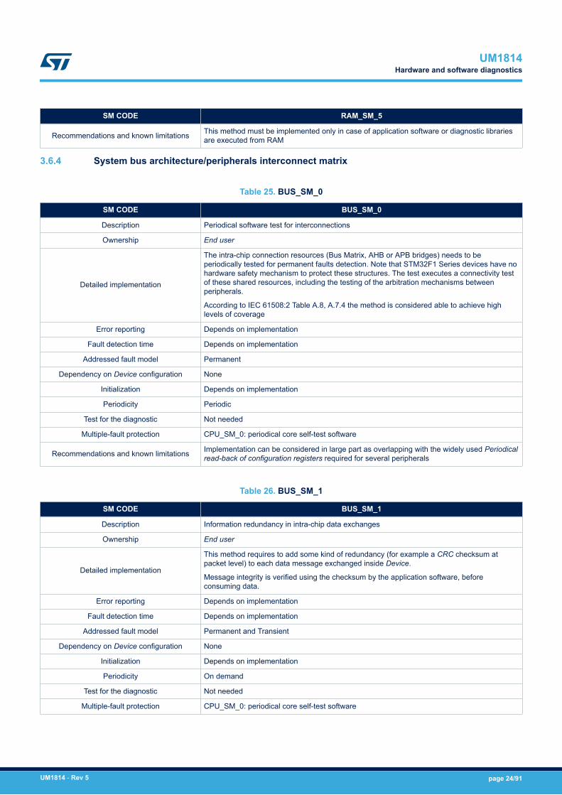
3.6.4 System bus architecture/peripherals interconnect matrix
Table 25. BUS_SM_0
SM CODE BUS_SM_0
Description Periodical software test for interconnections
Ownership End user
Detailed implementation
The intra-chip connection resources (Bus Matrix, AHB or APB bridges) needs to beperiodically tested for permanent faults detection. Note that STM32F1 Series devices have nohardware safety mechanism to protect these structures. The test executes a connectivity testof these shared resources, including the testing of the arbitration mechanisms betweenperipherals.
According to IEC 61508:2 Table A.8, A.7.4 the method is considered able to achieve highlevels of coverage
Error reporting Depends on implementation
Fault detection time Depends on implementation
Addressed fault model Permanent
Dependency on Device configuration None
Initialization Depends on implementation
Periodicity Periodic
Test for the diagnostic Not needed
Multiple-fault protection CPU_SM_0: periodical core self-test software
Recommendations and known limitations Implementation can be considered in large part as overlapping with the widely used Periodicalread-back of configuration registers required for several peripherals
Table 26. BUS_SM_1
SM CODE BUS_SM_1
Description Information redundancy in intra-chip data exchanges
Ownership End user
Detailed implementation
This method requires to add some kind of redundancy (for example a CRC checksum atpacket level) to each data message exchanged inside Device.
Message integrity is verified using the checksum by the application software, beforeconsuming data.
Error reporting Depends on implementation
Fault detection time Depends on implementation
Addressed fault model Permanent and Transient
Dependency on Device configuration None
Initialization Depends on implementation
Periodicity On demand
Test for the diagnostic Not needed
Multiple-fault protection CPU_SM_0: periodical core self-test software
UM1814Hardware and software diagnostics
UM1814 - Rev 5 page 24/91

SM CODE BUS_SM_1
Recommendations and known limitationsImplementation can be in large part overlapping with other safety mechanisms requiringinformation redundancy on data messages for communication peripherals. Optimizations aretherefore possible.
Table 27. LOCK_SM_0
SM CODE LOCK_SM_0
Description Lock mechanism for configuration options
Ownership ST
Detailed implementation
The STM32F1 Series devices feature spread protection to prevent unintended configurationchanges for some peripherals and system registers (for example PVD_LOCK, timers); thespread protection detects systematic faults in software application. The use of this method isencouraged to enhance the end application robustness to systematic faults.
Error reporting Not generated (when locked, register overwrites are just ignored)
Fault detection time NA
Addressed fault model None (Systematic only)
Dependency on Device configuration None
Initialization Depends on implementation
Periodicity Continuous
Test for the diagnostic Not needed
Multiple-fault protection Not needed
Recommendations and known limitations No DC associated because this test addresses systematic faults
UM1814Hardware and software diagnostics
UM1814 - Rev 5 page 25/91
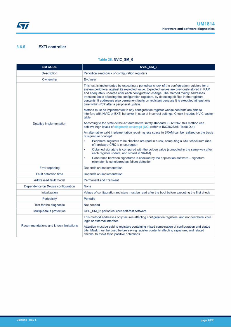
3.6.5 EXTI controller
Table 28. NVIC_SM_0
SM CODE NVIC_SM_0
Description Periodical read-back of configuration registers
Ownership End user
Detailed implementation
This test is implemented by executing a periodical check of the configuration registers for asystem peripheral against its expected value. Expected values are previously stored in RAMand adequately updated after each configuration change. The method mainly addressestransient faults affecting the configuration registers, by detecting bit flips in the registerscontents. It addresses also permanent faults on registers because it is executed at least onetime within PST after a peripheral update.
Method must be implemented to any configuration register whose contents are able tointerfere with NVIC or EXTI behavior in case of incorrect settings. Check includes NVIC vectortable.
According to the state-of-the-art automotive safety standard ISO26262, this method canachieve high levels of diagnostic coverage (DC) (refer to ISO26262:5, Table D.4)
An alternative valid implementation requiring less space in SRAM can be realized on the basisof signature concept:• Peripheral registers to be checked are read in a row, computing a CRC checksum (use
of hardware CRC is encouraged)• Obtained signature is compared with the golden value (computed in the same way after
each register update, and stored in SRAM)• Coherence between signatures is checked by the application software – signature
mismatch is considered as failure detection
Error reporting Depends on implementation
Fault detection time Depends on implementation
Addressed fault model Permanent and Transient
Dependency on Device configuration None
Initialization Values of configuration registers must be read after the boot before executing the first check
Periodicity Periodic
Test for the diagnostic Not needed
Multiple-fault protection CPU_SM_0: periodical core self-test software
Recommendations and known limitations
This method addresses only failures affecting configuration registers, and not peripheral corelogic or external interface.
Attention must be paid to registers containing mixed combination of configuration and statusbits. Mask must be used before saving register contents affecting signature, and relatedchecks, to avoid false positive detections.
UM1814Hardware and software diagnostics
UM1814 - Rev 5 page 26/91

Table 29. NVIC_SM_1
SM CODE NVIC_SM_1
Description Expected and unexpected interrupt check
Ownership End user
Detailed implementation
According to IEC 61508:2 Table A.1 recommendations, a diagnostic measure for continuous,absence or cross-over of interrupt must be implemented. The method of expected andunexpected interrupt check is implemented at application software level.
The guidelines for the implementation of the method are the following:• The interrupts implemented on the MCU are well documented, also reporting, when
possible, the expected frequency of each request (for example, the interrupts related toADC conversion completion that come on a regular basis).
• Individual counters are maintained for each interrupt request served, in order to detect ina given time frame the cases of a) no interrupt at all b) too many interrupt requests(“babbling idiot” interrupt source). The control of the time frame duration must beregulated according to the individual interrupt expected frequency.
• Interrupt vectors related to unused interrupt source point to a default handler thatreports, in case of triggering, a faulty condition (unexpected interrupt).
• In case an interrupt service routine is shared between different sources, a plausibilitycheck on the caller identity is implemented.
• Interrupt requests related to non-safety-related peripherals are handled with the samemethod here described, despite their originator safety classification
Error reporting Depends on implementation
Fault detection time Depends on implementation
Addressed fault model Permanent and Transient
Dependency on Device configuration None
Initialization Depends on implementation
Periodicity Continuous
Test for the diagnostic Not needed
Multiple-fault protection CPU_SM_0: periodical core self-test software
Recommendations and known limitations In order to decrease the complexity of method implementation, it is suggested to use pollingtechnique (when possible) instead of interrupt for end system implementation
3.6.6 Direct memory access controller (DMA)
Table 30. DMA_SM_0
SM CODE DMA_SM_0
Description Periodical read-back of configuration registers
Ownership End user
Detailed implementation
This method must be applied to DMA configuration register and channel addresses register aswell.
Detailed information on the implementation of this method can be found in Section 3.6.5 EXTI controller
Error reporting Refer to NVIC_SM_0
Fault detection time Refer to NVIC_SM_0
Addressed fault model Refer to NVIC_SM_0
Dependency on Device configuration Refer to NVIC_SM_0
Initialization Refer to NVIC_SM_0
Periodicity Refer to NVIC_SM_0
UM1814Hardware and software diagnostics
UM1814 - Rev 5 page 27/91

SM CODE DMA_SM_0
Test for the diagnostic Refer to NVIC_SM_0
Multiple-fault protection Refer to NVIC_SM_0
Recommendations and known limitations Refer to NVIC_SM_0
Table 31. DMA_SM_1
SM CODE DMA_SM_1
Description Information redundancy on data packet transferred via DMA
Ownership End user
Detailed implementation
This method is implemented adding to data packets transferred by DMA a redundancy check(such as CRC check, or similar one) with encoding capability. Full data packet redundancywould be overkilling.
The checksum encoding capability must be robust enough to guarantee at least 90%probability of detection for a single bit flip in the data packet
Consistency of data packet must be checked by the application software before consumingdata
Error reporting Depends on implementation
Fault detection time Depends on implementation
Addressed fault model Permanent and transient
Dependency on Device configuration None
Initialization Depends on implementation
Periodicity On demand
Test for the diagnostic Not needed
Multiple-fault protection CPU_SM_0: periodical core self-test software
Recommendations and known limitations To give an example about checksum encoding capability, using just a bit-by-bit addition isunappropriated
Table 32. DMA_SM_2
SM CODE DMA_SM_2
Description Information redundancy by including sender or receiver identifier on data packet transferredvia DMA
Ownership End user
Detailed implementation
This method helps to identify inside the MCU the source and the originator of the messageexchanged by DMA.
Implementation is realized by adding an additional field to protected message, with a codingconvention for message type identification fixed at Device level. Guidelines for theidentification fields are:• Identification field value must be different for each possible couple of sender or receiver
on DMA transactions• Values chosen must be enumerated and non-trivial• Coherence between the identification field value and the message type is checked by
application software before consuming data.
This method, when implemented in combination with DMA_SM_4, makes available a kind of“virtual channel” between source and destinations entities.
Error reporting Depends on implementation
Fault detection time Depends on implementation
UM1814Hardware and software diagnostics
UM1814 - Rev 5 page 28/91

SM CODE DMA_SM_2
Addressed fault model Permanent and transient
Dependency on Device configuration None
Initialization Depends on implementation
Periodicity On demand
Test for the diagnostic Not needed
Multiple-fault protection CPU_SM_0: periodical core self-test software
Recommendations and known limitations None
Table 33. DMA_SM_3
SM CODE DMA_SM_3
Description Periodical software test for DMA
Ownership End user
Detailed implementation
This method requires the periodical testing of the DMA basic functionality, implementedthrough a deterministic transfer of a data packet from one source to another (for example frommemory to memory) and the checking of the correct transfer of the message on the target.Data packets are composed by non-trivial patterns (avoid the use of 0x0000, 0xFFFF values)and organized in order to allow the detection during the check of the following failures:• incomplete packed transfer• errors in single transferred word• wrong order in packed transmitted data
Error reporting Depends on implementation
Fault detection time Depends on implementation
Addressed fault model Permanent
Dependency on Device configuration None
Initialization Depends on implementation
Periodicity Periodic
Test for the diagnostic Not needed
Multiple-fault protection CPU_SM_0: periodical core self-test software
Recommendations and known limitations None
Table 34. DMA_SM_4
SM CODE DMA_SM_4
Description DMA transaction awareness
Ownership End user
Detailed implementation
DMA transactions are non-deterministic by nature, because typically driven by external eventslike communication messages reception. Anyway, well-designed safety systems should keepmuch control as possible of events – refer for instance to IEC61508:3 Table 2 item 13requirements for software architecture.
This method is based on system knowledge of frequency and type of expected DMAtransaction. For instance, an externally connected sensor supposed to send periodically somemessages to a STM32 peripheral. Monitoring DMA transaction by a dedicated state machineallows to detect missing or unexpected DMA activities.
Error reporting Depends on implementation
Fault detection time Depends on implementation
UM1814Hardware and software diagnostics
UM1814 - Rev 5 page 29/91

SM CODE DMA_SM_4
Addressed fault model Permanent and transient
Dependency on Device configuration None
Initialization Depends on implementation
Periodicity Continuous
Test for the diagnostic Not needed
Multiple-fault protection CPU_SM_0: periodical core self-test software
Recommendations and known limitationsBecause DMA transaction termination is often linked to an interrupt generation,implementation of this method can be merged with the safety mechanism NVIC_SM_1:expected and unexpected interrupt check.
3.6.7 Controller area network (bxCAN)
Table 35. CAN_SM_0
SM CODE CAN_SM_0
Description Periodical read-back of configuration registers
Ownership End user
Detailed implementationThis method must be applied to CAN configuration registers.
Detailed information on the implementation of this method can be found in Section 3.6.5 EXTIcontroller.
Error reporting Refer to NVIC_SM_0
Fault detection time Refer to NVIC_SM_0
Addressed fault model Refer to NVIC_SM_0
Dependency on Device configuration Refer to NVIC_SM_0
Initialization Refer to NVIC_SM_0
Periodicity Refer to NVIC_SM_0
Test for the diagnostic Refer to NVIC_SM_0
Multiple faults protection Refer to NVIC_SM_0
Recommendations and known limitations Refer to NVIC_SM_0
UM1814Hardware and software diagnostics
UM1814 - Rev 5 page 30/91

Table 36. CAN_SM_1
SM CODE CAN_SM_1
Description Protocol error signals
Ownership ST
Detailed implementation
CAN communication module embeds protocol error checks (like error counters) conceived to detectnetwork-related abnormal conditions. These mechanisms are able anyway to detect a marginalpercentage of hardware random failures affecting the module itself.
Error signals connected to these checkers are normally handled in a standard communicationsoftware, so the overhead is reduced
Error reporting Several error condition are reported by flag bits in related CAN registers.
Fault detection time Depends on peripheral configuration (for example baud rate), refer to functional documentation
Addressed fault model Permanent and Transient
Dependency on Device configuration None
Initialization Depends on implementation
Periodicity Continuous
Test for the diagnostic NA
Multiple faults protection CAN_SM_2: Information redundancy techniques on messages, including end-to-end protection
Recommendations and known limitations Enabling related interrupt generation on the detection of errors is highly recommended.
UM1814Hardware and software diagnostics
UM1814 - Rev 5 page 31/91

Table 37. CAN_SM_2
SM CODE CAN_SM_2
Description Information redundancy techniques on messages, including end-to-end protection.
Ownership End user
Detailed implementation
This method aims to protect the communication between a peripheral and his external counterpartestablishing a kind of “protected” channel. The aim is to specifically address communication failure modes asreported in IEC61508:2, 7.4.11.1.
Implementation guidelines are the following:• Data packet must be protected (encapsulated) by an information redundancy check, like for instance a
CRC checksum computed over the packet and added to payload. Checksum encoding capability mustbe robust enough to guarantee at least 90% probability of detection for a single bit flip in the datapacket.
• Additional field added in payload reporting an unique identification of sender or receiver and an uniqueincreasing sequence packet number
• Timing monitoring of the message exchange (for example check the message arrival within theexpected time window), detecting therefore missed message arrival conditions
• Application software must verify before consuming data packet its consistency (CRC check), itslegitimacy (sender or receiver) and the sequence correctness (sequence number check, no packetslost)
Error reporting Depends on implementation
Fault detection time Depends on implementation
Addressed fault model Permanent and Transient
Dependency on Deviceconfiguration None
Initialization Depends on implementation
Periodicity On demand
Test for the diagnostic Not needed
Multiple faults protection CPU_SM_0: periodical core self-test software
Recommendations andknown limitations
Important note: it is assumed that the remote CAN counterpart has an equivalent capability of performing thechecks described.
A major overlap between the requirements of this method and the implementation of complex communicationsoftware protocols can exists. Due to large adoption of these protocols in industrial applications, optimizationscan be possible
3.6.8 Universal synchronous/asynchronous and low-power universal asynchronous receiver/transmitter (USART)
Table 38. UART_SM_0
SM CODE UART_SM_0
Description Periodical read-back of configuration registers
Ownership End user
Detailed implementationThis method must be applied to UART configuration registers.
Detailed information on the implementation of this method can be found in Section 3.6.5 EXTI controller.
Error reporting Refer to NVIC_SM_0
Fault detection time Refer to NVIC_SM_0
Addressed fault model Refer to NVIC_SM_0
Dependency on Device configuration Refer to NVIC_SM_0
UM1814Hardware and software diagnostics
UM1814 - Rev 5 page 32/91

SM CODE UART_SM_0
Initialization Refer to NVIC_SM_0
Periodicity Refer to NVIC_SM_0
Test for the diagnostic Refer to NVIC_SM_0
Multiple-fault protection Refer to NVIC_SM_0
Recommendations and known limitations Refer to NVIC_SM_0
Table 39. UART_SM_1
SM CODE UART_SM_1
Description Protocol error signals
Ownership ST
Detailed implementation
USART communication module embeds protocol error checks (like additional parity bit check,overrun, frame error) conceived to detect network-related abnormal conditions. Thesemechanisms are able anyway to detect a marginal percentage of hardware random failuresaffecting the module itself.
Error signals connected to these checkers are normally handled in a standard communicationsoftware, so the overhead is reduced.
Error reporting Error flag raise and optional Interrupt Event generation
Fault detection time Depends on peripheral configuration (for example baud rate), refer to functionaldocumentation
Addressed fault model Permanent and transient
Dependency on Device configuration None
Initialization Depends on implementation
Periodicity Continuous
Test for the diagnostic Not required
Multiple-fault protection UART_SM_2: Information redundancy techniques on messages
Recommendations and known limitationsUSART communication module is fitted by several different configurations – the actualcomposition of communication error checks depends on selected configuration.
Enabling related interrupt generation on the detection of errors is highly recommended.
Table 40. UART_SM_2
SM CODE UART_SM_2
Description Information redundancy techniques on messages
Ownership End user
Detailed implementation
This method is implemented adding to data packets transferred by UART a redundancy check(like a CRC check, or similar one) with encoding capability. The checksum encoding capabilitymust be robust enough to guarantee at least 90% probability of detection for a single bit flip inthe data packet.
Consistency of data packet must be checked by the application software before consumingdata.
Error reporting Depends on implementation
Fault detection time Depends on implementation
Addressed fault model Permanent and Transient
Dependency on Device configuration None
Initialization Depends on implementation
UM1814Hardware and software diagnostics
UM1814 - Rev 5 page 33/91
SM CODE UART_SM_2
Periodicity On demand
Test for the diagnostic Not needed
Multiple-fault protection CPU_SM_0: periodical core self-test software
Recommendations and known limitations
It is assumed that the remote UART counterpart has an equivalent capability of performing thecheck described.
Transmission full redundancy (message repetition) should not be used because its detectioncapability is limited to a subset of communication unit failure modes.
To give an example on checksum encoding capability, using just a bit-by-bit addition isunappropriated.
Table 41. UART_SM_3
SM CODE UART_SM_3
Description Information redundancy techniques on messages, including end-to-end protection.
Ownership End user
Detailed implementation
This method aims to protect the communication between a peripheral and his externalcounterpart establishing a kind of “protected” channel. The aim is to specifically addresscommunication failure modes as reported in IEC61508:2, 7.4.11.1.
Implementation guidelines are the following:• Data packet must be protected (encapsulated) by an information redundancy check, like
for instance a CRC checksum computed over the packet and added to payload.Checksum encoding capability must be robust enough to guarantee at least 90%probability of detection for a single bit flip in the data packet.
• Additional field added in payload reporting an unique identification of sender or receiverand an unique increasing sequence packet number
• Timing monitoring of the message exchange (for example check the message arrivalwithin the expected time window), detecting therefore missed message arrivalconditions
• Application software must verify before consuming data packet its consistency (CRCcheck), its legitimacy (sender or receiver) and the sequence correctness (sequencenumber check, no packets lost)
Error reporting Depends on implementation
Fault detection time Depends on implementation
Addressed fault model Permanent and Transient
Dependency on Device configuration None
Initialization Depends on implementation
Periodicity On demand
Test for the diagnostic Not needed
Multiple faults protection CPU_SM_0: periodical core self-test software
Recommendations and known limitations
Important note: it is assumed that the remote UART counterpart has an equivalent capabilityof performing the checks described.
A major overlap between the requirements of this method and the implementation of complexcommunication software protocols can exists. Due to large adoption of these protocols inindustrial applications, optimizations can be possible
UM1814Hardware and software diagnostics
UM1814 - Rev 5 page 34/91
3.6.9 Inter-integrated circuit (I2C)
Table 42. IIC_SM_0
SM CODE IIC_SM_0
Description PeriodiCAn8SM_cal read-back of configuration registers
Ownership End user
Detailed implementationThis method must be applied to I2C configuration registers.
Detailed information on the implementation of this method can be found in Section 3.6.5 EXTI controller.
Error reporting Refer to NVIC_SM_0
Fault detection time Refer to NVIC_SM_0
Addressed fault model Refer to NVIC_SM_0
Dependency on Device configuration Refer to NVIC_SM_0
Initialization Refer to NVIC_SM_0
Periodicity Refer to NVIC_SM_0
Test for the diagnostic Refer to NVIC_SM_0
Multiple-fault protection Refer to NVIC_SM_0
Recommendations and known limitations Refer to NVIC_SM_0
Table 43. IIC_SM_1
SM CODE IIC_SM_1
Description Protocol error signals
Ownership ST
Detailed implementation
I2C communication module embeds protocol error checks (like overrun, underrun, packeterror etc.) conceived to detect network-related abnormal conditions. These mechanisms areable anyway to detect a marginal percentage of hardware random failures affecting themodule itself.
Error reporting Error flag raise and optional Interrupt Event generation
Fault detection time Depends on peripheral configuration (for example baud rate), refer to functionaldocumentation.
Addressed fault model Permanent and transient
Dependency on Device configuration None
Initialization Depends on implementation
Periodicity Continuous
Test for the diagnostic Not needed
Multiple-fault protection IIC_SM_2: Information redundancy techniques on messages
Recommendations and known limitationsAdoption of SMBus option grants the activation of more efficient protocol-level hardwarechecks such as CRC-8 packet protection.
Enabling related interrupt generation on the detection of errors is highly recommended.
Table 44. IIC_SM_2
SM CODE IIC_SM_2
Description Information redundancy techniques on messages
UM1814Hardware and software diagnostics
UM1814 - Rev 5 page 35/91

SM CODE IIC_SM_2
Ownership End user
Detailed implementation
This method is implemented adding to data packets transferred by I2C a redundancy check(such as a CRC check, or similar one) with encoding capability. The checksum encodingcapability must be robust enough to guarantee at least 90% probability of detection for asingle bit flip in the data packet.
Consistency of data packet must be checked by the application software before consumingdata.
Error reporting Depends on implementation
Fault detection time Depends on implementation
Addressed fault model Permanent and transient
Dependency on Device configuration None
Initialization Depends on implementation
Periodicity On demand
Test for the diagnostic Not needed
Multiple-fault protection CPU_SM_0: periodical core self-test software
Recommendations and known limitations
It is assumed that the remote I2C counterpart has an equivalent capability of performing thecheck described.
Transmission full redundancy (message repetition) should not be used because its detectioncapability is limited to a subset of communication unit failure modes.
To give an example on checksum encoding capability, using just a bit-by-bit addition isunappropriated.
This method is overlapped with IIC_SM_3 if hardware handled CRC insertion is possible.
Table 45. IIC_SM_3
SM CODE IIC_SM_3
Description CRC packet-level
Ownership ST
Detailed implementation I2C communication module allows to activate for specific mode of operation (SMBus) theautomatic insertion (and check) of CRC checksums to packet data.
Error reporting Error flag raise and optional Interrupt Event generation
Fault detection time Depends on peripheral configuration (for example baud rate), refer to functionaldocumentation.
Addressed fault model Permanent and transient
Dependency on Device configuration None
Initialization Depends on implementation
Periodicity Continuous
Test for the diagnostic Not needed
Multiple-fault protection IIC_SM_2: Information redundancy techniques on messages
Recommendations and known limitationsThis method can be part of the implementation for IIC_SM_2
Enabling related interrupt generation on the detection of errors is highly recommended.
UM1814Hardware and software diagnostics
UM1814 - Rev 5 page 36/91
Table 46. IIC_SM_4
SM CODE IIC_SM_4
Description Information redundancy techniques on messages, including end-to-end protection.
Ownership End user
Detailed implementationThis method aims to protect the communication between a I2C peripheral and his externalcounterpart.
Refer to UART_SM_3 description for detailed information.
Error reporting Refer to UART_SM_3
Fault detection time Refer to UART_SM_3
Addressed fault model Refer to UART_SM_3
Dependency on Device configuration Refer to UART_SM_3
Initialization Refer to UART_SM_3
Periodicity Refer to UART_SM_3
Test for the diagnostic Refer to UART_SM_3
Multiple-fault protection Refer to UART_SM_3
Recommendations and known limitationsImportant note: it is assumed that the remote I2C counterpart has an equivalent capability ofperforming the checks described.
Refer to UART_SM_3 for further notice.
3.6.10 Serial peripheral interface (SPI)
Table 47. SPI_SM_0
SM CODE SPI_SM_0
Description Periodical read-back of configuration registers
Ownership End user
Detailed implementationThis method must be applied to SPI configuration registers.
Detailed information on the implementation of this method can be found in Section 3.6.5 EXTI controller.
Error reporting Refer to NVIC_SM_0
Fault detection time Refer to NVIC_SM_0
Addressed fault model Refer to NVIC_SM_0
Dependency on Device configuration Refer to NVIC_SM_0
Initialization Refer to NVIC_SM_0
Periodicity Refer to NVIC_SM_0
Test for the diagnostic Refer to NVIC_SM_0
Multiple-fault protection Refer to NVIC_SM_0
Recommendations and known limitations Refer to NVIC_SM_0
Table 48. SPI_SM_1
SM CODE SPI_SM_1
Description Protocol error signals
Ownership ST
UM1814Hardware and software diagnostics
UM1814 - Rev 5 page 37/91

SM CODE SPI_SM_1
Detailed implementation
SPI communication module embeds protocol error checks (like overrun, underrun, timeoutand so on) conceived to detect network-related abnormal conditions. These mechanisms areable anyway to detect a marginal percentage of hardware random failures affecting themodule itself.
Error reporting Error flag raise and optional interrupt event generation
Fault detection time Depends on peripheral configuration (for example baud rate), refer to functionaldocumentation.
Addressed fault model Permanent and transient
Dependency on Device configuration None
Initialization Depends on implementation
Periodicity Continuous
Test for the diagnostic NA
Multiple-fault protection SPI_SM_2: Information redundancy techniques on messages
Recommendations and known limitations Enabling related interrupt generation on the detection of errors is highly recommended.
Table 49. SPI_SM_2
SM CODE SPI_SM_2
Description Information redundancy techniques on messages
Ownership End user
Detailed implementation
This method is implemented adding to data packets transferred by SPI a redundancy check(such as a CRC check, or similar one) with encoding capability. The checksum encodingcapability must be robust enough to guarantee at least 90% probability of detection for asingle bit flip in the data packet.
Consistency of data packet must be checked by the application software before consumingdata.
Error reporting Depends on implementation
Fault detection time Depends on implementation
Addressed fault model Permanent and transient
Dependency on Device configuration None
Initialization Depends on implementation
Periodicity On demand
Test for the diagnostic Not needed
Multiple-fault protection CPU_SM_0: periodical core self-test software
Recommendations and known limitations
It is assumed that the remote SPI counterpart has an equivalent capability of performing thecheck described.
Transmission full redundancy (message repetition) should not be used because its detectioncapability is limited to a subset of communication unit failure modes.
To give an example on checksum encoding capability, using just a bit-by-bit addition isunappropriated.
This method is overlapped with SSP_SM_3 if hardware handled CRC insertion is possible.
Table 50. SPI_SM_3
SM CODE SPI_SM_3
Description CRC packet-level
UM1814Hardware and software diagnostics
UM1814 - Rev 5 page 38/91

SM CODE SPI_SM_3
Ownership ST
Detailed implementation SPI communication module allows to activate automatic insertion (and check) of CRC-8 orCRC-18 checksums to packet data.
Error reporting Error flag raise and optional Interrupt Event generation
Fault detection time Depends on peripheral configuration (for example baud rate), refer to functionaldocumentation.
Addressed fault model Permanent and transient
Dependency on Device configuration None
Initialization Depends on implementation
Periodicity Continuous
Test for the diagnostic Not needed
Multiple-fault protection SPI_SM_2: Information redundancy techniques on messages
Recommendations and known limitationsThis method can be part of the implementation for SPI_SM_2
Enabling related interrupt generation on the detection of errors is highly recommended.
Table 51. SPI_SM_4
SM CODE SPI_SM_4
Description Information redundancy techniques on messages, including end-to-end protection.
Ownership End user
Detailed implementationThis method aims to protect the communication between SPI peripheral and his externalcounterpart.
Refer to UART_SM_3 description for detailed information.
Error reporting Refer to UART_SM_3
Fault detection time Refer to UART_SM_3
Addressed fault model Refer to UART_SM_3
Dependency on Device configuration Refer to UART_SM_3
Initialization Refer to UART_SM_3
Periodicity Refer to UART_SM_3
Test for the diagnostic Refer to UART_SM_3
Multiple-fault protection Refer to UART_SM_3
Recommendations and known limitationsImportant note: it is assumed that the remote SPI counterpart has an equivalent capability ofperforming the checks described.
Refer to UART_SM_3 for further notice.
UM1814Hardware and software diagnostics
UM1814 - Rev 5 page 39/91

3.6.11 USB on-the-go full-speed (OTG_FS)
Table 52. USB_SM_0
SM CODE USB_SM_0
Description Periodical read-back of configuration registers
Ownership End user
Detailed implementationThis method must be applied to USB configuration registers.
Detailed information on the implementation of this method can be found in Section 3.6.5 EXTIcontroller.
Error reporting Refer to NVIC_SM_0
Fault detection time Refer to NVIC_SM_0
Addressed fault model Refer to NVIC_SM_0
Dependency on Device configuration Refer to NVIC_SM_0
Initialization Refer to NVIC_SM_0
Periodicity Refer to NVIC_SM_0
Test for the diagnostic Refer to NVIC_SM_0
Multiple faults protection Refer to NVIC_SM_0
Recommendations and known limitations Refer to NVIC_SM_0
Table 53. USB_SM_1
SM CODE USB_SM_1
Description Protocol error signals
Ownership ST
Detailed implementationUSB communication module embeds protocol error checks (like overrun, underrun, NRZI, bitstuffing etc.) conceived to detect network-related abnormal conditions. These mechanisms are ableanyway to detect a marginal percentage of hardware random failures affecting the module itself
Error reporting Error flag raise and optional Interrupt Event generation
Fault detection time Depends on peripheral configuration (for example baud rate), refer to functional documentation
Addressed fault model Permanent and Transient
Dependency on Device configuration None
Initialization Depends on implementation
Periodicity Continuous
Test for the diagnostic Not needed
Multiple faults protection USB_SM_2: Information redundancy techniques on messages
Recommendations and known limitations Enabling related interrupt generation on the detection of errors is highly recommended.
UM1814Hardware and software diagnostics
UM1814 - Rev 5 page 40/91
Table 54. USB_SM_2
SM CODE USB_SM_2
Description Information redundancy techniques on messages
Ownership ST or End user
Detailed implementationThe implementation of required information redundancy on messages, USB communication moduleis fitted by hardware capability. It basically allows to activate the automatic insertion (and check) ofCRC checksums to packet data.
Error reporting Error flag raise and optional Interrupt Event generation
Fault detection time Depends on peripheral configuration (for example baud rate), refer to functional documentation
Addressed fault model Permanent and Transient
Dependency on Device configuration None
Initialization Error reporting configuration, if interrupt events are planned
Periodicity Continuous
Test for the diagnostic Not needed
Multiple faults protection CPU_SM_0: periodical core self-test software
Recommendations and known limitations None
Table 55. USB_SM_3
SM CODE USB_SM_3
Description Information redundancy techniques on messages, including end-to-end protection.
Ownership End user
Detailed implementationThis method aims to protect the communication between an USB peripheral and his externalcounterpart.
Refer to UART_SM_3 description for detailed information
Error reporting Refer to UART_SM_3
Fault detection time Refer to UART_SM_3
Addressed fault model Refer to UART_SM_3
Dependency on Device configuration Refer to UART_SM_3
Initialization Refer to UART_SM_3
Periodicity Refer to UART_SM_3
Test for the diagnostic Refer to UART_SM_3
Multiple faults protection Refer to UART_SM_3
Recommendations and known limitationsThis method apply in case USB bulk or isochronous transfers are used. For other transfers modesthe USB hardware protocol already implements several features of this requirement.
Refer to UART_SM_3 for further notice
UM1814Hardware and software diagnostics
UM1814 - Rev 5 page 41/91

3.6.12 Analog-to-digital converters (ADC)
Table 56. ADC_SM_0
SM CODE ADC_SM_0
Description Periodical read-back of configuration registers
Ownership End user
Detailed implementationThis method must be applied to ADC configuration registers.
Detailed information on the implementation of this method can be found in Section 3.6.5 EXTIcontroller
Error reporting Refer to NVIC_SM_0
Fault detection time Refer to NVIC_SM_0
Addressed fault model Refer to NVIC_SM_0
Dependency on Device configuration Refer to NVIC_SM_0
Initialization Refer to NVIC_SM_0
Periodicity Refer to NVIC_SM_0
Test for the diagnostic Refer to NVIC_SM_0
Multiple faults protection Refer to NVIC_SM_0
Recommendations and known limitations Refer to NVIC_SM_0
Table 57. ADC_SM_1
SM CODE ADC_SM_1
Description Multiple acquisition by application software
Ownership End user
Detailed implementationThis method implements a timing information redundancy by executing multiple acquisitions on thesame input signal. Multiple acquisition data are then combined by a filter algorithm to determine thesignal correct value
Error reporting Depends on implementation
Fault detection time Depends on implementation
Addressed fault model Permanent and Transient
Dependency on Device configuration None
Initialization Depends on implementation
Periodicity Continuous
Test for the diagnostic Not needed
Multiple faults protection CPU_SM_0: periodical core self-test software
Recommendations and known limitationsIt is highly probable that this recommendation is satisfied by design by the end user applicationsoftware. Usage of multiple acquisitions followed by average operations is a common technique inindustrial applications where it is needed to survive with spurious EMI disturbs on sensor lines
UM1814Hardware and software diagnostics
UM1814 - Rev 5 page 42/91

Table 58. ADC_SM_2
SM CODE ADC_SM_2
Description Range check by application software
Ownership End user
Detailed implementation
The guidelines for the implementation of the method are the following:• The expected range of the data to be acquired are investigated and adequately documented. Note
that in a well-designed application it is improbable that during normal operation an input signal has avery near or over the upper and lower rail limit (saturation in signal acquisition).
• If the application software is aware of the state of the system, this information is to be used in therange check implementation. For example, if the ADC value is the measurement of a current througha power load, reading an abnormal value such as a current flowing in opposite direction versus theload supply may indicate a fault in the acquisition module.
• As the ADC module is shared between different possible external sources, the combination ofplausibility checks on the different signals acquired can help to cover the whole input range in a veryefficient way
Error reporting Depends on implementation
Fault detection time Depends on implementation
Addressed fault model Permanent and Transient
Dependency on Deviceconfiguration None
Initialization Depends on implementation
Periodicity Continuous
Test for the diagnostic Not needed
Multiple faults protection CPU_SM_0: periodical core self-test software
Recommendations and knownlimitations
The implementation (and the related diagnostic efficiency) of this safety mechanism are strongly application-dependent
Table 59. ADC_SM_3
SM CODE ADC_SM_3
Description Periodical software test for ADC
Ownership End user
Detailed implementation
The method is implemented acquiring multiple signals and comparing the read value with theexpected one, supposed to be know. Method can be implemented with different level of complexity:• Basic complexity: acquisition and check of upper or lower rails (VDD or VSS) and internal
reference voltage• High complexity: in addition to basic complexity tests, acquisition of a DAC output connected
to ADC input and checking all voltage excursion and linearity
Error reporting Depends on implementation
Fault detection time Depends on implementation
Addressed fault model Permanent
Dependency on Device configuration None
Initialization Depends on implementation
Periodicity Periodic
Test for the diagnostic Not needed
Multiple faults protection CPU_SM_0: periodical core self-test software
Recommendations and known limitations Combination of two different complexity method can be used to better optimize test frequency inhigh demand safety functions
UM1814Hardware and software diagnostics
UM1814 - Rev 5 page 43/91

Table 60. ADC_SM_4
SM CODE ADC_SM_4
Description 1oo2 scheme for ADC inputs
Ownership End user
Detailed implementationThis safety mechanism is implemented using two different SAR ADC channels belonging toseparate ADC modules to acquire the same input signal. The application software checks thecoherence between the two readings.
Error reporting Depends on implementation
Fault detection time Depends on implementation
Addressed fault model Permanent and Transient
Dependency on Device configuration None
Initialization Depends on implementation
Periodicity On demand
Test for the diagnostic Not needed
Multiple faults protection ADC_SM_0: Periodical read-back of ADC configuration registers
Recommendations and known limitations This method can be used in conjunction with ADC_SM_0/ ADC_SM_2/ ADC_SM_3 to achievehighest level of ADC module diagnostic coverage
3.6.13 Digital-to-analog converter (DAC)
Table 61. DAC_SM_0
SM CODE DAC_SM_0
Description Periodical read-back of configuration registers
Ownership End user
Detailed implementationThis method must be applied to DAC configuration registers.
Detailed information on the implementation of this method can be found in Section 3.6.5 EXTI controller.
Error reporting Refer to NVIC_SM_0
Fault detection time Refer to NVIC_SM_0
Addressed fault model Refer to NVIC_SM_0
Dependency on Device configuration Refer to NVIC_SM_0
Initialization Refer to NVIC_SM_0
Periodicity Refer to NVIC_SM_0
Test for the diagnostic Refer to NVIC_SM_0
Multiple-fault protection Refer to NVIC_SM_0
Recommendations and known limitations Refer to NVIC_SM_0
Table 62. DAC_SM_1
SM CODE DAC_SM_1
Description DAC output loopback on ADC channel
Ownership End user
Detailed implementation Implementation is realized by routing the active DAC output to one ADC channel, and bychecking the output current value with his expected one.
UM1814Hardware and software diagnostics
UM1814 - Rev 5 page 44/91

SM CODE DAC_SM_1
Error reporting Depends on implementation
Fault detection time Depends on implementation
Addressed fault model Permanent and transient
Dependency on Device configuration None
Initialization Depends on implementation
Periodicity Continuous or on demand
Test for the diagnostic Not needed
Multiple faults protection CPU_SM_0: periodical core self-test software
Recommendations and known limitationsEfficiency versus transient failures is linked to final application characteristics. We define asTm the minimum duration of DAC wrong signal permanence required to violate the relatedsafety function(s). Efficiency is maximized when execution test frequency is higher than 1/Tm.
3.6.14 Basic timers TIM 6/7
Table 63. GTIM_SM_0
SM CODE GTIM_SM_0
Description Periodical read-back of configuration registers
Ownership End user
Detailed implementationThis method must be applied to basic counter timer TIM6 or TIM7 configuration registers.
Detailed information on the implementation of this method can be found in Section 3.6.5 EXTIcontroller
Error reporting Refer to NVIC_SM_0
Fault detection time Refer to NVIC_SM_0
Addressed fault model Refer to NVIC_SM_0
Dependency on Device configuration Refer to NVIC_SM_0
Initialization Refer to NVIC_SM_0
Periodicity Refer to NVIC_SM_0
Test for the diagnostic Refer to NVIC_SM_0
Multiple faults protection Refer to NVIC_SM_0
Recommendations and known limitations Refer to NVIC_SM_0
UM1814Hardware and software diagnostics
UM1814 - Rev 5 page 45/91
Table 64. GTIM_SM_1
SM CODE GTIM_SM_1
Description 1oo2 for counting timers
Ownership End user
Detailed implementation
This method implements via software a 1oo2 scheme between two counting resources.
The guidelines for the implementation of the method are the following:• Two timers are programmed with same time base or frequency.• In case of timer use as a time base: use in the application software one of the timer as time base
source, and the other one just for check. Coherence check for the 1oo2 is done at application level,comparing two counters values each time the timer value is used to affect safety function.
• In case of interrupt generation usage: use the first timer as main interrupt source for the serviceroutines, and use the second timer as a “reference” to be checked at the initial of interrupt routine
Error reporting Depends on implementation
Fault detection time Depends on implementation
Addressed fault model Permanent and Transient
Dependency on Deviceconfiguration None
Initialization Depends on implementation
Periodicity On demand
Test for the diagnostic Not needed
Multiple faults protection CPU_SM_0: periodical core self-test software
Recommendations and knownlimitations
Tolerance implementation in timer checks is recommended to avoid false positive outcomes of thediagnostic
3.6.15 Advanced, general and low-power timers TIM1/2/3/4/5/8/9/10/11/12/13/14/15/16/17Note: As the timers are equipped with many different channels, each independent from the others, and possibly
programmed to realize different features, the safety mechanism is selected individually for each channel.
Table 65. ATIM_SM_0
SM CODE ATIM_SM_0
Description Periodical read-back of configuration registers
Ownership End user
Detailed implementation
This method must be applied to advanced, general and low-power timersTIM1/2/3/4/5/8/9/10/11/12/13/14/15/16/17 configuration registers.
Detailed information on the implementation of this method can be found in Section 3.6.5 EXTIcontroller.
Error reporting Refer to NVIC_SM_0
Fault detection time Refer to NVIC_SM_0
Addressed fault model Refer to NVIC_SM_0
Dependency on Device configuration Refer to NVIC_SM_0
Initialization Refer to NVIC_SM_0
Periodicity Refer to NVIC_SM_0
Test for the diagnostic Refer to NVIC_SM_0
Multiple faults protection Refer to NVIC_SM_0
Recommendations and known limitations Refer to NVIC_SM_0
UM1814Hardware and software diagnostics
UM1814 - Rev 5 page 46/91

Table 66. ATIM_SM_1
SM CODE ATIM_SM_1
Description 1oo2 for counting timers
Ownership End user
Detailed implementation
This method implements via software a 1oo2 scheme between two counting resources.
The guidelines for the implementation of the method are the following:• Two timers are programmed with same time base or frequency.• In case of timer use as a time base: use in the application software one of the timer as time base
source, and the other one just for check. Coherence check for the 1oo2 is done at application level,comparing two counters values each time the timer value is used to affect safety function.
• In case of interrupt generation usage: use the first timer as main interrupt source for the serviceroutines, and use the second timer as a “reference” to be checked at the initial of interrupt routine
Error reporting Depends on implementation
Fault detection time Depends on implementation
Addressed fault model Permanent and Transient
Dependency on Deviceconfiguration None
Initialization Depends on implementation
Periodicity On demand
Test for the diagnostic Not needed
Multiple faults protection CPU_SM_0: periodical core self-test software
Recommendations and knownlimitations
Tolerance implementation in timer checks is recommended to avoid false positive outcomes of thediagnostic.
This method apply to timer channels merely used as elapsed time counters
Table 67. ATIM_SM_2
SM CODE ATIM_SM_2
Description 1oo2 for input capture timers
Ownership End user
Detailed implementation
This method is conceived to protect timers used for external signal acquisition and measurement,like “input capture” and “encoder reading”. Implementation requires to connect the external signalsalso to a redundant timer, and to perform a coherence check on the measured data at applicationlevel.
Coherence check between timers is executed each time the reading is used by the applicationsoftware
Error reporting Depends on implementation
Fault detection time Depends on implementation
Addressed fault model Permanent and Transient
Dependency on Device configuration None
Initialization Depends on implementation
Periodicity On demand
Test for the diagnostic Not needed
Multiple faults protection CPU_SM_0: periodical core self-test software
Recommendations and knownlimitations
To reduce the potential effect of common cause failures, it is suggested to use for redundant check achannel belonging to a different timer module and mapped to non-adjacent pin on the devicepackage
UM1814Hardware and software diagnostics
UM1814 - Rev 5 page 47/91

Table 68. ATIM_SM_3
SM CODE ATIM_SM_3
Description Loop-back scheme for PWM outputs
Ownership End user
Detailed implementation
This method is implemented by connecting the PWM to a separate timer channel to acquire the generatedwaveform characteristics.
The guidelines are the following:• Both PWM frequency and duty cycle are measured and checked versus the expected value.• To reduce the potential effect of common cause failure, it is suggested to use for the loopback check a
channel belonging to a different timer module and mapped to non-adjacent pins on the device package.
This measure can be replaced under the end-user responsibility by different loopback schemes already inplace in the final application and rated as equivalent. For example if the PWM is used to drive an externalpower load, the reading of the on-line current value can be used instead of the PWM duty cycle measurement.
Error reporting Depends on implementation
Fault detection time Depends on implementation
Addressed fault model Permanent and Transient
Dependency on Deviceconfiguration None
Initialization Depends on implementation
Periodicity Continuous
Test for the diagnostic Not needed
Multiple faults protection CPU_SM_0: periodical core self-test software
Recommendations andknown limitations
Efficiency versus transient failures is linked to final application characteristics. We define as Tm the minimumduration of PWM wrong signal permanence (wrong frequency, wrong duty, or both) required to violate therelated safety function(s). Efficiency is maximized when execution test frequency is higher than 1/Tm
Table 69. ATIM_SM_4
SM CODE ATIM_SM_4
Description Lock bit protection for timers
Ownership ST
Detailed implementationThis safety mechanism allows the end user to lock down specified configuration options, avoidingunintended modifications by application software. It addresses therefore software developmentsystematic faults
Error reporting NA
Fault detection time NA
Addressed fault model None (Fault avoidance)
Dependency on Device configuration None
Initialization Lock protection must be enabled using LOCK bits in the TIMx_BDTR register
Periodicity Continuous
Test for the diagnostic NA
Multiple faults protection NA
Recommendations and known limitations This method does not addresses timer configuration changes due to soft-errors
UM1814Hardware and software diagnostics
UM1814 - Rev 5 page 48/91

3.6.16 General-purpose input/output (GPIO) - port A/B/C/D/E/F/G
Table 70. GPIO_SM_0
SM CODE GPIO_SM_0
Description Periodical read-back of configuration registers
Ownership End user
Detailed implementationThis method must be applied to GPIO configuration registers.
Detailed information on the implementation of this method can be found in Section 3.6.5 EXTI controller.
Error reporting Refer to NVIC_SM_0
Fault detection time Refer to NVIC_SM_0
Addressed fault model Refer to NVIC_SM_0
Dependency on Device configuration GPIO availability can differ according to part number
Initialization Refer to NVIC_SM_0
Periodicity Refer to NVIC_SM_0
Test for the diagnostic Refer to NVIC_SM_0
Multiple-fault protection Refer to NVIC_SM_0
Recommendations and known limitations Refer to NVIC_SM_0
Table 71. GPIO_SM_1
SM CODE GPIO_SM_1
Description 1oo2 for input GPIO lines
Ownership End user
Detailed implementation
This method addresses GPIO lines used as inputs. Implementation is done by connecting theexternal safety-related signal to two independent GPIO lines. Comparison between the twoGPIO values is executed by application software each time the signal is used to affectapplication software behavior.
Error reporting Depends on implementation
Fault detection time Depends on implementation
Addressed fault model Permanent and transient
Dependency on Device configuration None
Initialization Depends on implementation
Periodicity On demand
Test for the diagnostic Not needed
Multiple-fault protection CPU_SM_0: periodical core self-test software
Recommendations and known limitations
To reduce the potential impact of common cause failure, it is recommended to use GPIO lines:• belonging to different I/O ports (for instance port A and B)• with different bit port number (for instance PA1 and PB5)• mapped to non-adjacent pins on the device package
Table 72. GPIO_SM_2
SM CODE GPIO_SM_2
Description Loopback scheme for output GPIO lines
UM1814Hardware and software diagnostics
UM1814 - Rev 5 page 49/91

SM CODE GPIO_SM_2
Ownership End user
Detailed implementation
This method addresses GPIO lines used as outputs. Implementation is done by a loopbackscheme, connecting the output to a different GPIO line programmed as input and by using theinput line to check the expected value on output port. Comparison is executed by applicationsoftware periodically and each time output is updated.
Error reporting Depends on implementation
Fault detection time Depends on implementation
Addressed fault model Permanent and transient
Dependency on Device configuration None
Initialization Depends on implementation
Periodicity Continuous
Test for the diagnostic Not needed
Multiple-fault protection CPU_SM_0: periodical core self-test software
Recommendations and known limitations
To reduce the potential impact of common cause failure, it is recommended to use GPIO lines:• belonging to different I/O ports (for instance port A and B)• with different bit port number (for instance PA1 and PB5)• mapped to non-adjacent pins on the device package
Efficiency versus transient failures is linked to final application characteristics. We define asTm the minimum duration of GPIO output wrong signal permanence required to violate therelated safety function(s). Efficiency is maximized when execution test frequency is higherthan 1/Tm.
Table 73. GPIO_SM_3
SM CODE GPIO_SM_3
Description GPIO port configuration lock register
Ownership ST
Detailed implementation
This safety mechanism prevents configuration changes for GPIO registers; it addressestherefore systematic faults in software application.
The use of this method is encouraged to enhance the end-application robustness forsystematic faults.
Error reporting Depends on implementation
Fault detection time Depends on implementation
Addressed fault model None (Systematic only)
Dependency on Device configuration None
Initialization Application software must apply a correct write sequence to LCKK bit (bit 16 of theGPIOx_LCKR register) after writing the final GPIO configuration.
Periodicity Continuous
Test for the diagnostic Not needed
Multiple-fault protection Not needed
Recommendations and known limitations This method does not address transient faults (soft errors) that can possibly cause bit-flips onGPIO registers at running time.
UM1814Hardware and software diagnostics
UM1814 - Rev 5 page 50/91

3.6.17 Real-time clock module (RTC)
Table 74. RTC_SM_0
SM CODE RTC_SM_0
Description Periodical read-back of configuration registers
Ownership End user
Detailed implementationThis method must be applied to RTC configuration registers.
Detailed information on the implementation of this method can be found in Section 3.6.5 EXTI controller.
Error reporting Refer to NVIC_SM_0
Fault detection time Refer to NVIC_SM_0
Addressed fault model Refer to NVIC_SM_0
Dependency on Device configuration Refer to NVIC_SM_0
Initialization Refer to NVIC_SM_0
Periodicity Refer to NVIC_SM_0
Test for the diagnostic Refer to NVIC_SM_0
Multiple-fault protection Refer to NVIC_SM_0
Recommendations and known limitations Refer to NVIC_SM_0
Table 75. RTC_SM_1
SM CODE RTC_SM_1
Description Application check of running RTC
Ownership End user
Detailed implementation
The application software implements some plausibility check on RTC calendar or timing data,mainly after a power-up and further date reading by RTC.
The guidelines for the implementation of the method are the following:• RTC backup registers are used to store coded information in order to detect the
absence of VBAT during power-off period.• RTC backup registers are used to periodically store compressed information on current
date or time• The application software executes minimal consistence checks for date reading after
power-on (detecting “past” date or time retrieve).• Application software periodically checks that RTC is actually running, by reading RTC
timestamp progress and comparing with an elapsed time measurement based onSTM32 internal clock or timers.
Error reporting Depends on implementation
Fault detection time Depends on implementation
Addressed fault model Permanent and transient
Dependency on Device configuration None
Initialization Depends on implementation
Periodicity Periodical
Test for the diagnostic Not needed
Multiple-fault protection CPU_SM_0: periodical core self-test software
UM1814Hardware and software diagnostics
UM1814 - Rev 5 page 51/91

SM CODE RTC_SM_1
Recommendations and known limitations
This method provides a limited diagnostic coverage for RTC failure modes. In case of Enduser application where RTC timestamps accuracy can affect in severe way the safety function(for example, medical data storage devices), it is strongly recommended to adopt moreefficient system-level measures.
Table 76. RTC_SM_2
SM CODE RTC_SM_2
Description Information redundancy on backup registers
Ownership End user
Detailed implementation
Data stored in RTC backup registers must be protected by a checksum with encoding capability (forinstance, CRC). Checksum must be checked by application software before consuming storeddata.
This method guarantees data versus erases due to backup battery failures
Error reporting Depends on implementation
Fault detection time Depends on implementation
Addressed fault model Permanent and Transient
Dependency on Device configuration None
Initialization Depends on implementation
Periodicity On demand
Test for the diagnostic Not needed
Multiple-fault protection CPU_SM_0: periodical core self-test software
Recommendations and known limitations None
Table 77. RTC_SM_3
SM CODE RTC_SM_3
Description Application-level measures to detect failures in timestamps/event capture
Ownership End user
Detailed implementationThis method must detect failures affecting the RTC capability to correct execute thetimestamps/event capture functions. Due to the nature strictly application-dependent of thissolution, no detailed guidelines for its implementation are given here.
Error reporting Depends on implementation
Fault detection time Depends on implementation
Addressed fault model Permanent and transient
Dependency on Device configuration None
Initialization Depends on implementation
Periodicity Periodic / On demand
Test for the diagnostic Not needed
Multiple-fault protection CPU_SM_0: Periodical core self-test software
Recommendations and known limitations
This method must be used only if the timestamps/event capture function is used in the safetyfunction implementation. It is worth noting that the use of timestamp / event capture in safety-related applications with the MCU in Sleep or Stop mode is prevented by the assumedrequirement ASR7 (refer to Section 3.3.1 Safety requirement assumptions).
UM1814Hardware and software diagnostics
UM1814 - Rev 5 page 52/91

3.6.18 Power controller (PWR)
Table 78. VSUP_SM_0
SM CODE VSUP_SM_0
Description Periodical read-back of configuration registers
Ownership End user
Detailed implementationThis method must be applied to configuration registers.
Detailed information on the implementation of this method can be found in Section 3.6.5 EXTIcontroller.
Error reporting Refer to NVIC_SM_0
Fault detection time Refer to NVIC_SM_0
Addressed fault model Refer to NVIC_SM_0
Dependency on Device configuration Refer to NVIC_SM_0
Initialization Refer to NVIC_SM_0
Periodicity Refer to NVIC_SM_0
Test for the diagnostic Refer to NVIC_SM_0
Multiple faults protection Refer to NVIC_SM_0
Recommendations and known limitations Refer to NVIC_SM_0
Table 79. VSUP_SM_1
SM CODE VSUP_SM_1
Description Supply voltage internal monitoring (PVD)
Ownership ST
Detailed implementationThe device features an embedded programmable voltage detector (PVD) that monitors the VDDpower supply and compares it to the VPVD threshold. An interrupt can be generated when VDDdrops below the VPVD threshold or when VDD is higher than the VPVD threshold
Error reporting Interrupt Event generation
Fault detection time Depends on threshold programming, refer to functional documentation
Addressed fault model Permanent and Transient
Dependency on Device configuration None
Initialization Protection enable by PVDE bit and threshold programming in Power control register (PWR_CR)
Periodicity Continuous
Test for the diagnostic Not needed
Multiple faults protection DIAG_SM_0: Periodical read-back of hardware diagnostics configuration registers
Recommendations and knownlimitations
Internal monitoring PVD has limited capability to address failures affecting STM32F1 Series internalvoltage regulator. Refer to device FMEA for details
Enabling related interrupt generation on the detection of errors is highly recommended.
UM1814Hardware and software diagnostics
UM1814 - Rev 5 page 53/91
Table 80. VSUP_SM_2
SM CODE VSUP_SM_2
Description Independent watchdog
Ownership ST
Detailed implementation
Failures in the power supplies for digital logic (core or peripherals) may lead to alteration of theapplication software timing, which can be detected by IWDG as safety mechanism introduced tomonitor the application software control flow. Refer to CPU_SM_1 and CPU_SM_6 for furtherinformation.
Error reporting Reset signal generation
Fault detection time Depends on implementation (watchdog timeout interval)
Addressed fault model Permanent
Dependency on Device configuration None
Initialization IWDG activation. It is recommended to use the “Hardware watchdog” in Option byte settings (IWDG isautomatically enabled after reset)
Periodicity Continuous
Test for the diagnostic Not needed
Multiple faults protection CPU_SM_1: control flow monitoring in application software
Recommendations and knownlimitations
In specific part numbers IWDG can be fed by a power supply independent from the one used for CPUcore and main peripherals. Such diversity helps to increase the protection guaranteed by IWDG frommain power supply anomalies.
The adoption of an external watchdog (refer to CPU_SM_5) adds further diversity.
Table 81. VSUP_SM_3
SM CODE VSUP_SM_3
Description Internal temperature sensor check
Ownership End user
Detailed implementationThe internal temperature sensor must be periodically tested in order to detect abnormal increase ofthe die temperature – hardware faults in supply voltage system may cause excessive powerconsumption and consequent temperature rise
Error reporting Depends on implementation
Fault detection time Depends on implementation
Addressed fault model Permanent
Dependency on Device configuration None
Initialization None
Periodicity Periodic
Test for the diagnostic Not needed
Multiple faults protection CPU_SM_0: periodical core self-test software
Recommendations and known limitationsThis method also mitigates the eventuality of common-cause affecting the MCU and due to too hightemperature.
Refer to the device datasheet to set the threshold temperature
UM1814Hardware and software diagnostics
UM1814 - Rev 5 page 54/91

3.6.19 Reset and clock controller (RCC)
Table 82. CLK_SM_0
SM CODE CLK_SM_0
Description Periodical read-back of configuration registers
Ownership End user
Detailed implementation
This method must be applied to configuration registers for clock and reset system (refer toRCC register map).
Detailed information on the implementation of this method can be found in Section 3.6.5 EXTI controller.
Error reporting Refer to NVIC_SM_0
Fault detection time Refer to NVIC_SM_0
Addressed fault model Refer to NVIC_SM_0
Dependency on Device configuration Refer to NVIC_SM_0
Initialization Refer to NVIC_SM_0
Periodicity Refer to NVIC_SM_0
Test for the diagnostic Refer to NVIC_SM_0
Multiple-fault protection Refer to NVIC_SM_0
Recommendations and known limitations Refer to NVIC_SM_0
Table 83. CLK_SM_1
SM CODE CLK_SM_1
Description Clock security system (CSS)
Ownership ST
Detailed implementation
The clock security system (CSS) detects the loss of high-speed external (HSE) oscillator clockactivity and executes the corresponding recovery action, such as:• Switch-off HSE• Commutation on the HSI• Generation of related NMI
Error reporting NMI
Fault detection time Depends on implementation (clock frequency value).
Addressed fault model Permanent and transient
Dependency on Device configuration None
Initialization CSS protection must be enabled through Clock interrupt register (RCC_CIR) after bootstabilization.
Periodicity Continuous
Test for the diagnostic CLK_SM_0: periodical read-back of configuration registers
Multiple-fault protection CPU_SM_5: external watchdog
Recommendations and known limitations It is recommended to carefully read reference manual instruction on NMI generation, in orderto correctly managing the faulty situation by Application software.
UM1814Hardware and software diagnostics
UM1814 - Rev 5 page 55/91

Table 84. CLK_SM_2
SM CODE CLK_SM_2
Description Independent watchdog
Ownership ST
Detailed implementation The independent watchdog IWDG is able to detect failures in internal main MCU clock (lowerfrequency).
Error reporting Reset signal generation
Fault detection time Depends on implementation (watchdog timeout interval).
Addressed fault model Permanent
Dependency on Device configuration None
Initialization IWDG activation. It is recommended to use the hardware watchdog in Option byte settings(IWDG is automatically enabled after reset).
Periodicity Continuous
Test for the diagnostic Not needed
Multiple-fault protection CPU_SM_1: control flow monitoring in application software
Recommendations and known limitations If IWDG window option is used, End user must consider possible tolerance in applicationsoftware execution, to avoid false error reports (affecting system availability).
3.6.20 Independent and system window watchdogs (IWDG and WWDG)
Table 85. WDG_SM_0
SM CODE WDG_SM_0
Description Periodical read-back of configuration registers
Ownership End user
Detailed implementationThis method must be applied to IWDG/WWDG configuration registers.
Detailed information on the implementation of this method can be found in Section 3.6.5 EXTI controller.
Error reporting Refer to NVIC_SM_0
Fault detection time Refer to NVIC_SM_0
Addressed fault model Refer to NVIC_SM_0
Dependency on Device configuration Refer to NVIC_SM_0
Initialization Refer to NVIC_SM_0
Periodicity Refer to NVIC_SM_0
Test for the diagnostic Refer to NVIC_SM_0
Multiple-fault protection Refer to NVIC_SM_0
Recommendations and known limitations Refer to NVIC_SM_0
UM1814Hardware and software diagnostics
UM1814 - Rev 5 page 56/91
Table 86. WDG_SM_1
SM CODE WDG_SM_1
Description Software test for watchdog at startup
Ownership End user
Detailed implementation
This safety mechanism ensures the right functionality of the internal watchdogs in use. Atstartup, the software test programs the watchdog with the required expiration timeout, stores aspecific non-trivial code in SRAM and waits for the reset signal. After the watchdog reset, thesoftware understands that the watchdog has correctly triggered, and does not execute theprocedure again.
Error reporting Depends on implementation
Fault detection time Depends on implementation
Addressed fault model Permanent
Dependency on Device configuration None
Initialization Depends on implementation
Periodicity Startup (see below)
Test for the diagnostic Not needed
Multiple-fault protection CPU_SM_0: periodical core self-test software
Recommendations and known limitationsIn a typical End user application, this test can be executed only at startup and duringmaintenance or offline periods. It could be associated to IEC61508 concept of “proof test” andso it cannot be accounted for a diagnostic coverage contribution during operating time.
3.6.21 Debug support (DBG)
Table 87. DBG_SM_0
SM CODE DBG_SM_0
Description Independent watchdog
Ownership ST
Detailed implementationThe debug unintentional activation due to hardware random fault results in the massivedisturbance of CPU operations, leading to intervention of the independent watchdog oralternately, the other system watchdog WWGDG or an external one.
Error reporting Reset signal generation
Fault detection time Depends on implementation (watchdog timeout interval).
Addressed fault model Permanent
Dependency on Device configuration None
Initialization Depends on implementation
Periodicity Continuous
Test for the diagnostic Not needed
Multiple-fault protection CPU_SM_1: control flow monitoring in application software
Recommendations and known limitations None
UM1814Hardware and software diagnostics
UM1814 - Rev 5 page 57/91

3.6.22 Cyclic redundancy-check module (CRC)
Table 88. CRC_SM_0
SM CODE CRC_SM_0
Description CRC self-coverage
Ownership ST
Detailed implementation
The CRC algorithm implemented in this module (CRC-32 Ethernet polynomial: 0x4C11DB7) offersexcellent features in terms of error detection in the message. Therefore permanent and transientfaults affecting CRC computations are easily detected by any operations using the module torecompute an expected signature
Error reporting Depends on implementation
Fault detection time Depends on implementation
Addressed fault model Permanent and Transient
Dependency on Device configuration None
Initialization Depends on implementation
Periodicity Continuous
Test for the diagnostic Not needed
Multiple faults protection CPU_SM_0: periodical core self-test software
Recommendations and known limitations None
3.6.23 System configuration controller (SYSCFG)
Table 89. SYSCFG_SM_0
SM CODE SYSCFG_SM_0
Description Periodical read-back of configuration registers
Ownership End user
Detailed implementation
This method must be applied to System Configuration controller configuration registers.
This method is strongly recommended to protect registers related to hardware diagnosticsactivation and error reporting chain related features.
Detailed information on the implementation of this method can be found in Section 3.6.5 EXTI controller.
Error reporting Refer to NVIC_SM_0
Fault detection time Refer to NVIC_SM_0
Addressed fault model Refer to NVIC_SM_0
Dependency on Device configuration Refer to NVIC_SM_0
Initialization Refer to NVIC_SM_0
Periodicity Refer to NVIC_SM_0
Test for the diagnostic Refer to NVIC_SM_0
Multiple-fault protection Refer to NVIC_SM_0
Recommendations and known limitations This method is mainly overlapped by several other “configuration register read-backs”required for other MCU peripherals. It is reported here for the sake of completeness.
UM1814Hardware and software diagnostics
UM1814 - Rev 5 page 58/91
Table 90. DIAG_SM_0
SM CODE DIAG_SM_0
Description Periodical read-back of hardware diagnostics configuration registers
Ownership End user
Detailed implementation
In STM32F1 Series several hardware-based safety mechanisms are available (they arereported in this manual with the wording Ownership=ST). This method must be applied to anyconfiguration register related to diagnostic measure operations, including error reporting. Enduser must therefore individuate configuration registers related to:• Hardware diagnostic enable• Interrupt/NMI enable (if used for diagnostic error management)
Error reporting Refer to NVIC_SM_0
Fault detection time Refer to NVIC_SM_0
Addressed fault model Refer to NVIC_SM_0
Dependency on Device configuration Refer to NVIC_SM_0
Initialization Refer to NVIC_SM_0
Periodicity Refer to NVIC_SM_0
Test for the diagnostic Refer to NVIC_SM_0
Multiple-fault protection Refer to NVIC_SM_0
Recommendations and known limitations Refer to NVIC_SM_0
3.6.24 Secure digital input/output interface (SDIO)
Table 91. SDIO_SM_0
SM CODE SDIO_SM_0
Description Periodical read-back of SDIO configuration registers
Ownership End user
Detailed implementationThis method must be applied to SDIO configuration registers.
Detailed information on the implementation of this method can be found in Section 3.6.5 EXTIcontroller
Error reporting Refer to NVIC_SM_0
Fault detection time Refer to NVIC_SM_0
Addressed fault model Refer to NVIC_SM_0
Dependency on MCU configuration Refer to NVIC_SM_0
Initialization Refer to NVIC_SM_0
Periodicity Refer to NVIC_SM_0
Test for the diagnostic Refer to NVIC_SM_0
Multiple faults protection Refer to NVIC_SM_0
Recommendations and known limitations Refer to NVIC_SM_0
Table 92. SDIO_SM_1
SM CODE SDIO_SM_1
Description Protocol error signals including hardware CRC
Ownership ST
UM1814Hardware and software diagnostics
UM1814 - Rev 5 page 59/91

SM CODE SDIO_SM_1
Detailed implementation
SDIO communication module embeds protocol error checks (like overrun, underrun, timeout etc.)and CRC-packet checks as well, conceived to detect network-related abnormal conditions. Thesemechanisms are able anyway to detect a percentage of hardware random failures affecting themodule itself
Error reporting Error flag raise and optional Interrupt Event generation
Fault detection time Depends on peripheral configuration (for example baud rate), please refer to functionaldocumentation
Addressed fault model Permanent and Transient
Dependency on MCU configuration None
Initialization Depends on implementation
Periodicity Continuous
Test for the diagnostic N/A
Multiple faults protection SDIO_SM_2: Information redundancy techniques on messages
Recommendations and known limitations Enabling related interrupt generation on the detection of errors is highly recommended.
Table 93. SDIO_SM_2
SM CODE SDIO_SM_2
Description Information redundancy techniques on messages
Ownership End user
Detailed implementation
This method is implemented adding to data packets transferred by SDIO a redundancy check (like aCRC check, or similar one) with encoding capability. The checksum encoding capability must berobust enough to guarantee at least 90% probability of detection for a single bit flip in the data packet.
Consistency of data packet must be checked by the application software before consuming data
Error reporting Depends on implementation
Fault detection time Depends on implementation
Addressed fault model Permanent and Transient
Dependency on MCU configuration None
Initialization Depends on implementation
Periodicity On demand
Test for the diagnostic Not needed
Multiple faults protection CPU_SM_0: Periodical core self test software
Recommendations and knownlimitations
To give an example on checksum encoding capability, using just a bit-by-bit addition isunappropriated.
This safety mechanism can overlap with information redundancy techniques implemented at systemlevel to address failure of physical device connected to SDIO/SMMMC port
Note: The safety mechanisms mentioned above are addressing the SDIO interface included in STM32 MCUs. Noclaims are done in this Safety Manual about the mitigation of hardware random faults affecting the externalmemory connected to SDIO port.
3.6.25 Ethernet (ETH): media access control (MAC) with DMA controller
Table 94. ETH_SM_0
SM CODE ETH_SM_0
Description Periodical read-back of Ethernet configuration registers
UM1814Hardware and software diagnostics
UM1814 - Rev 5 page 60/91
SM CODE ETH_SM_0
Ownership End user
Detailed implementationThis method must be applied to Ethernet configuration registers (including those relate to unusedmodule features). Detailed information on the implementation of this method can be found inSection 3.6.5 EXTI controller.
Error reporting Refer to NVIC_SM_0
Fault detection time Refer to NVIC_SM_0
Addressed fault model Refer to NVIC_SM_0
Dependency on MCU configuration Refer to NVIC_SM_0
Initialization Refer to NVIC_SM_0
Periodicity Refer to NVIC_SM_0
Test for the diagnostic Refer to NVIC_SM_0
Multiple faults protection Refer to NVIC_SM_0
Recommendations and known limitations Refer to NVIC_SM_0
Table 95. ETH_SM_1
SM CODE ETH_SM_1
Description Protocol error signals including hardware CRC
Ownership ST
Detailed implementation
Ethernet communication module embeds protocol error checks (like overrun, underrun, timeout,packet composition violation etc.) and CRC-packet checks as well, conceived to detect network-related abnormal conditions. These mechanisms are able anyway to detect a percentage ofhardware random failures affecting the module itself.
Error reporting Error flag raise and optional Interrupt Event generation
Fault detection time Depends on peripheral configuration (e.g. baud rate), refer to functional documentation
Addressed fault model Permanent and transient
Dependency on MCU configuration None
Initialization Depends on implementation
Periodicity Continuous
Test for the diagnostic N/A
Multiple faults protection ETH_SM_2 information redundancy techniques on messages, including end-to-end protection
Recommendations and known limitations Enabling related interrupt generation on the detection of errors is highly recommended.
Table 96. ETH_SM_2
SM CODE ETH_SM_2
Description Information redundancy techniques on messages, including end-to-end protection
Ownership End user
Detailed implementation
This method aim to protect the communication between a peripheral and its external counterpart. Itis used in Ethernet local safety concept to address failures not detected by ETH_SM_1 and toincrease its associated diagnostic coverage.
Refer to CAN_SM_2 description for detailed information.
Error reporting Depends on implementation
Fault detection time Depends on implementation
UM1814Hardware and software diagnostics
UM1814 - Rev 5 page 61/91

SM CODE ETH_SM_2
Addressed fault model Permanent and transient
Dependency on MCU configuration None
Initialization Depends on implementation
Periodicity On demand
Test for the diagnostic Not needed
Multiple faults protection CPU_SM_0: periodical core self test software
Recommendations and known limitations The implementation on the application software of complex Ethernet-based communication stacks(like TCP/IP) is able to satisfy the requirements of this method.
Note: The use of the DMA feature inside Ethernet module brings to adopt the same set of safety mechanism definedfor the system DMA (refer to Direct memory access controller (DMA)
3.6.26 Flexible static memory controller (FSMC)
Table 97. FSMC_SM_0
SM CODE FSMC_SM_0
Description Control flow monitoring in application software
Ownership End user
Detailed implementation
If FSMC is used to connect an external memory containing software code to be executed by the CPU,permanent and transient faults affecting the FSMC memory controller are able to interfere with theaccess operation by the CPU, leading to wrong data or instruction fetches. A strong control flowmechanism linked to a system watchdog is able to detect such failures, in case they interfere with theexpected flow of the application software.
The implementation of this method is identical to the one reported for CPU_SM_1, refer there fordetails
Error reporting Depends on implementation
Fault detection time Depends on implementation. Higher value is fixed by watchdog timeout interval
Addressed fault model Permanent and Transient
Dependency on Device configuration FSMC interface is available only on selected part numbers
Initialization Depends on implementation
Periodicity Continuous
Test for the diagnostic N/A
Multiple faults protection CPU_SM_0: Periodical core self test software
Recommendations and knownlimitations This mechanism must be used just if FSMC external memory is used to store executable programs
UM1814Hardware and software diagnostics
UM1814 - Rev 5 page 62/91

Table 98. FSMC_SM_1
SM CODE FSMC_SM_1
Description Information redundancy on external memory connected to FSMC
Ownership End user
Detailed implementation
If FSMC interface is used to connect an external memory where safety-relevant data are stored,information redundancy techniques for stored data are able to address faults affecting the FSMCinterface. The possible techniques are:
To use redundant copies of safety relevant data and perform coherence check before consuming.
To organize data in arrays and compute the checksum field to be checked before use
Error reporting Depends on implementation
Fault detection time Depends on implementation
Addressed fault model Permanent and Transient
Dependency on Device configuration FSMC interface is available only on selected part numbers
Initialization Depends on implementation
Periodicity On demand
Test for the diagnostic Not needed
Multiple faults protection CPU_SM_0: Periodical core self test software
Recommendations and knownlimitations
This mechanism must be used just if FSMC external memory is used to store safety-related data.
This safety mechanism can overlap with information redundancy techniques implemented at systemlevel to address failure of physical device connected to FSMC port
Table 99. FSMC_SM_2
SM CODE FSMC_SM_2
Description Periodical read-back of FSMC configuration registers
Ownership End user
Detailed implementationThis method must be applied to FSMC configuration registers.
Detailed information on the implementation of this method can be found in Section 3.6.5 EXTIcontroller.
Error reporting Refer to NVIC_SM_0
Fault detection time Refer to NVIC_SM_0
Addressed fault model Refer to NVIC_SM_0
Dependency on Device configuration FSMC interface is available only on selected part numbers
Initialization Refer to NVIC_SM_0
Periodicity Refer to NVIC_SM_0
Test for the diagnostic Refer to NVIC_SM_0
Multiple faults protection Refer to NVIC_SM_0
Recommendations and known limitations Refer to NVIC_SM_0
UM1814Hardware and software diagnostics
UM1814 - Rev 5 page 63/91
Table 100. FSMC_SM_3
SM CODE FSMC_SM_3
Description ECC engine on NAND interface in FSMC module
Ownership ST
Detailed implementationThe FMC NAND Card controller includes two error correction code computation hardware blocks,one per memory bank. They reduce the host CPU workload when processing the ECC by software.
ECC mechanism protects data integrity on the external memory connected to NAND port
Error reporting Refer to functional documentation
Fault detection time ECC bits are checked during a memory reading
Addressed fault model Permanent and Transient
Dependency on Device configuration FSMC interface is available only on selected part numbers
Initialization None
Periodicity Continuous
Test for the diagnostic Not needed
Multiple faults protection FSMC_SM_2: Periodical read-back of FSMC configuration registers
Recommendations and known limitationsThis method has negligible efficiency in detecting hardware random failures affecting the FSMCinterface. It can be part of End user safety concept because addressing memories outsideSTM32F1 Series MCU
3.6.27 HDMI-CEC module
Table 101. HDMI_SM_0
SM CODE HDMI_SM_0
Description Periodical read-back of HDMI CEC configuration registers
Ownership End user or ST
Detailed implementation This method must be applied to HDMI CEC configuration registers. Detailed information on theimplementation of this method can be found in NVIC_SM_0
Error reporting Refer to NVIC_SM_0
Fault detection time Refer to NVIC_SM_0
Addressed fault model Refer to NVIC_SM_0
Dependency on MCU configuration Refer to NVIC_SM_0
Initialization Refer to NVIC_SM_0
Periodicity Refer to NVIC_SM_0
Test for the diagnostic Refer to NVIC_SM_0
Multiple faults protection Refer to NVIC_SM_0
Recommendations and known limitations Refer to NVIC_SM_0
Table 102. HDMI_SM_1
SM CODE HDMI_SM_1
Description Protocol error signals
Ownership ST
UM1814Hardware and software diagnostics
UM1814 - Rev 5 page 64/91

SM CODE HDMI_SM_1
Detailed implementation
HDMI communication module embeds protocol error checks (like overrun, underrun, bit timingviolations, etc.) conceived to detect network-related abnormal conditions. The semechanisms areable anyway to detect a marginal percentage of hardware random failures affecting the moduleitself.
Error reporting Error flag raise and optional Interrupt Event generation
Fault detection time Depends on peripheral configuration (e.g. baud rate), refer to functional documentation
Addressed fault model Permanent and transient
Dependency on MCU configuration None
Initialization Depends on implementation
Periodicity Continuous
Test for the diagnostic Not needed
Multiple faults protection HDMI_SM_2: information redundancy techniques on messages
Recommendations and known limitations Enabling related interrupt generation on the detection of errors is highly recommended.
Table 103. HDMI_SM_2
SM CODE HDMI_SM_2
Description Information redundancy techniques on messages
Ownership End user
Detailed implementation
This method is implemented adding to data packets transferred by HDMI/CEC a redundancy check (like aCRC check, or similar one) with encoding capability. The checksum encoding capability must be robustenough to guarantee at least 90% probability of detection for a single bit flip in the data packet. Theconsistency of data packet must be checked by the application software before consuming data. Thismethod must be applied to HDMI CEC configuration registers. Detailed information on the implementationof this method can be found in NVIC_SM_0
Error reporting Depends on implementation
Fault detection time Depends on implementation
Addressed fault model Permanent and transient
Dependency on MCUconfiguration None
Initialization Depends on implementation
Periodicity On demand
Test for the diagnostic Not needed
Multiple faults protection CPU_SM_0: periodical core self test software
Recommendations and knownlimitations
It is assumed that the remote HDMI/CEC counterpart must have an equivalent capability of performing thecheck described. The transmission full redundancy (message repetition) should not be used because itsdetection capability is limited to a subset of communication unit failure modes. To give an example onchecksum encoding capability, using just a bit-by-bit addition will be unappropriated.
3.6.28 Disable and periodic cross-check of unintentional activation of unused peripheralsThis section reports the safety mechanism that addresses peripherals not used by the safety application, or notused at all.
Table 104. FFI_SM_0
SM CODE FFI_SM_0
Description Unused peripherals disable
UM1814Hardware and software diagnostics
UM1814 - Rev 5 page 65/91

SM CODE FFI_SM_0
Ownership End user
Detailed implementation
This method contributes to the reduction of the probability of cross-interferences caused byperipherals not used by the software application, in case a hardware failure causes anunintentional activation.
After the system boot, the application software must disable all unused peripherals with thisprocedure:• Enable reset flag on AHB and APB peripheral reset register• Disable clock distribution on AHB and APB peripheral clock enable register
Error reporting NA
Fault detection time NA
Addressed fault model NA
Dependency on Device configuration None
Initialization NA
Periodicity Startup
Test for the diagnostic Not needed
Multiple faults protection FFI_SM_1: Periodical read-back of interference avoidance registers
Recommendations and known limitations None
Table 105. FFI_SM_1
SM CODE FFI_SM_1
Description Periodical read-back of interference avoidance registers
Ownership End user
Detailed implementation
This method contributes to the reduction of the probability of cross-interferences betweenperipherals that can potentially conflict on the same input/output pins, including for instanceunused peripherals. This diagnostic measure must be applied to following registers:• clock enable and disable registers• alternate function programming registers
Detailed information on the implementation of this method can be found in Section 3.6.5 EXTI controller.
Error reporting Refer to NVIC_SM_0
Fault detection time Refer to NVIC_SM_0
Addressed fault model Refer to NVIC_SM_0
Dependency on Device configuration Refer to NVIC_SM_0
Initialization Refer to NVIC_SM_0
Periodicity Refer to NVIC_SM_0
Test for the diagnostic Refer to NVIC_SM_0
Multiple faults protection Refer to NVIC_SM_0
Recommendations and known limitations Refer to NVIC_SM_0
UM1814Hardware and software diagnostics
UM1814 - Rev 5 page 66/91

3.6.29 System
Table 106. DUAL_SM_0
SM CODE DUAL_SM_0
Description Cross-check between two STM32 MCUs
Ownership End user
Detailed implementation
This method is implemented in the spirit of technique described in IEC61508-7, A.3.5 “Reciprocal comparisonby software”, which is rated in IEC61508-2 Table A.4 as capable to achieve high level of diagnostic coverage.
The two processing units exchange data reciprocally, and a fail in the comparison is considered as a detectionof a failure in one of the two unit. The guidelines for the implementation are the following:• Data exchanged include output results, intermediate results (1) and the results of each software-
implemented safety mechanisms executed on periodical basis on both MCUs (for example CPU_SM_0)• Software routines devoted to data exchange/comparison must be logically separated from the software
implementing the safety function(s).• Systematic capability of data exchange/comparison software must be equal or above the one of the
software implementing the safety function(s).• Independency and lack of interference between the software implementing the data exchange/
comparison and the one implementing the safety function(s) must be proven.• Frequency of data exchange/comparison is imposed by the system PST (refer to (1) related timing
constraints for “periodic” safety mechanisms), except for output results which needs to be exchanged/compared at the same rate they are potentially updated.
Fault detection time Depends on implementation
Addressed fault model Permanent and transient
Dependency on Deviceconfiguration None
Initialization Depends on implementation
Periodicity Periodic
Test for the diagnostic N/A
Multiple faults protection CPU_SM_0: periodical core self-test software (individually executed on both processing units)
Recommendations andknown limitations
This method is usually rated as “optional” because it is not strictly needed in the framework of 1oo2architecture described in Section 3.2.4 ; anyway, it is included here only for its use in such an architecture.
This method can provide additional safety margin for systems needing further protection against faultaccumulation.
Because this method could be a potential source of common cause failure between the two 1oo2 channels (incase of incorrect implementation), End User is recommended to carefully follow above the reported guidelines(box “Detailed Implementation”).
1. It is defined here “intermediate result” the value of each variable able to directly influence the final individualchannel output. To give some examples:- if final output is a value resulting from some computation (for example a PWM rate), “intermediate results”are the values of each variable included in such computation.- if final output if the result of a decision (for example GPIO value decided on the basis of the comparisonbetween values), “intermediate results” are the values of each variable involved in such decision.
3.7 Conditions of use
The table below provides a summary of the safety concept recommendations reported in Section 3.6: Descriptionof hardware and software diagnostics. The conditions of use to be applied to STM32F1 Series devices arereported in form of safety mechanism requirements. Exception is represented by some conditions of useintroduced by FMEA analysis in order to correctly address specific failure modes. These conditions of use arereported at the end of the table presented in this section.Rank column reports how related safety mechanism has been considered during the analysis, with followingmeaning:
UM1814Conditions of use
UM1814 - Rev 5 page 67/91
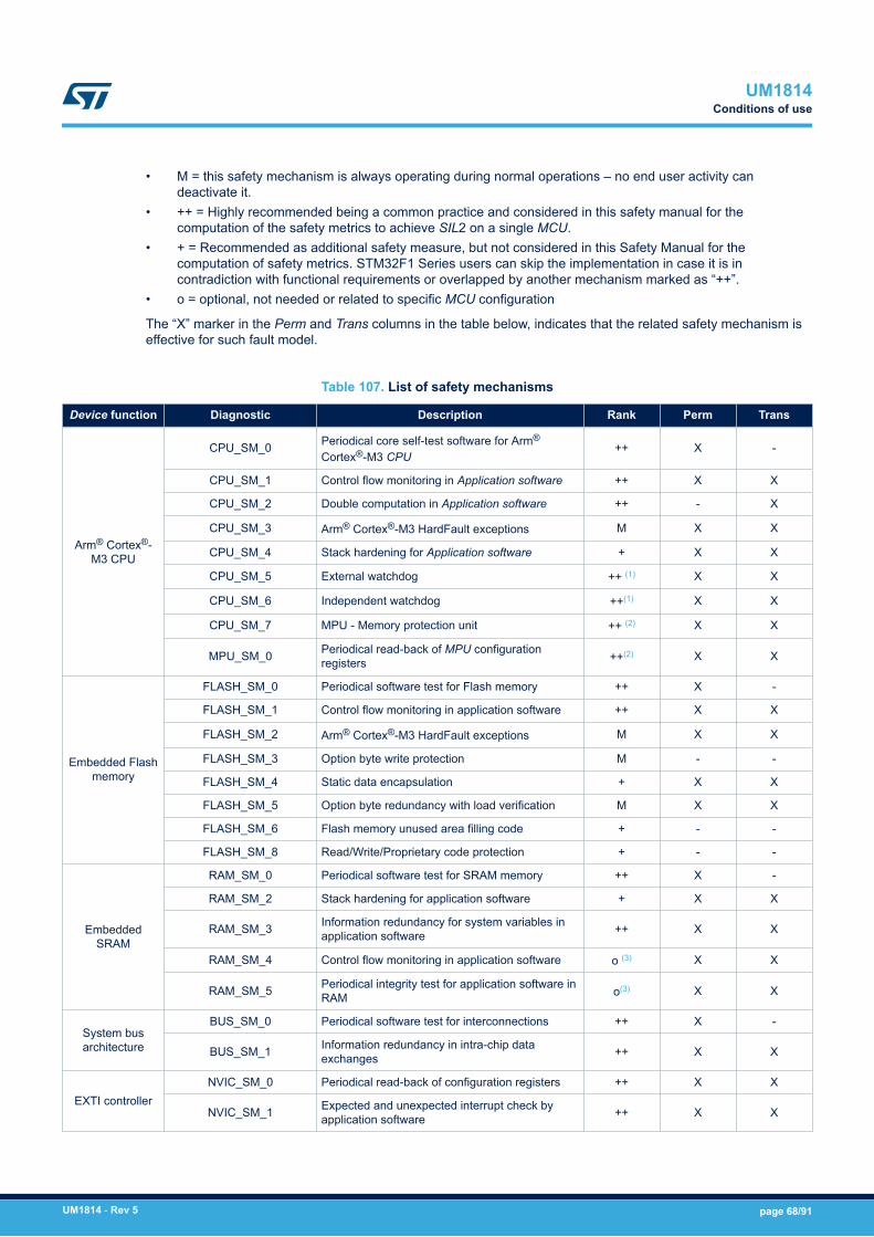
• M = this safety mechanism is always operating during normal operations – no end user activity candeactivate it.
• ++ = Highly recommended being a common practice and considered in this safety manual for thecomputation of the safety metrics to achieve SIL2 on a single MCU.
• + = Recommended as additional safety measure, but not considered in this Safety Manual for thecomputation of safety metrics. STM32F1 Series users can skip the implementation in case it is incontradiction with functional requirements or overlapped by another mechanism marked as “++”.
• o = optional, not needed or related to specific MCU configuration
The “X” marker in the Perm and Trans columns in the table below, indicates that the related safety mechanism iseffective for such fault model.
Table 107. List of safety mechanisms
Device function Diagnostic Description Rank Perm Trans
Arm® Cortex®-M3 CPU
CPU_SM_0 Periodical core self-test software for Arm®
Cortex®-M3 CPU++ X -
CPU_SM_1 Control flow monitoring in Application software ++ X X
CPU_SM_2 Double computation in Application software ++ - X
CPU_SM_3 Arm® Cortex®-M3 HardFault exceptions M X X
CPU_SM_4 Stack hardening for Application software + X X
CPU_SM_5 External watchdog ++ (1) X X
CPU_SM_6 Independent watchdog ++(1) X X
CPU_SM_7 MPU - Memory protection unit ++ (2) X X
MPU_SM_0 Periodical read-back of MPU configurationregisters ++(2) X X
Embedded Flashmemory
FLASH_SM_0 Periodical software test for Flash memory ++ X -
FLASH_SM_1 Control flow monitoring in application software ++ X X
FLASH_SM_2 Arm® Cortex®-M3 HardFault exceptions M X X
FLASH_SM_3 Option byte write protection M - -
FLASH_SM_4 Static data encapsulation + X X
FLASH_SM_5 Option byte redundancy with load verification M X X
FLASH_SM_6 Flash memory unused area filling code + - -
FLASH_SM_8 Read/Write/Proprietary code protection + - -
EmbeddedSRAM
RAM_SM_0 Periodical software test for SRAM memory ++ X -
RAM_SM_2 Stack hardening for application software + X X
RAM_SM_3 Information redundancy for system variables inapplication software ++ X X
RAM_SM_4 Control flow monitoring in application software o (3) X X
RAM_SM_5 Periodical integrity test for application software inRAM o(3) X X
System busarchitecture
BUS_SM_0 Periodical software test for interconnections ++ X -
BUS_SM_1 Information redundancy in intra-chip dataexchanges ++ X X
EXTI controllerNVIC_SM_0 Periodical read-back of configuration registers ++ X X
NVIC_SM_1 Expected and unexpected interrupt check byapplication software ++ X X
UM1814Conditions of use
UM1814 - Rev 5 page 68/91

Device function Diagnostic Description Rank Perm Trans
DMA
DMA_SM_0 Periodical read-back of configuration registers ++ X X
DMA_SM_1 Information redundancy on data packettransferred via DMA ++ X X
DMA_SM_2Information redundancy by including sender orreceiver identifier on data packet transferred viaDMA
++ X X
DMA_SM_3 Periodical software test for DMA ++ X -
DMA_SM_4 DMA transaction awareness ++ X X
CAN
CAN_SM_0 Periodical read-back of configuration registers ++ X X
CAN_SM_1 Protocol error signals ++ X X
CAN_SM_2 Information redundancy techniques onmessages, including end-to-end protection ++ X X
UART
UART_SM_0 Periodical read-back of configuration registers ++ X X
UART_SM_1 Protocol error signals ++ X X
UART_SM_2 Information redundancy techniques on messages ++ X X
UART_SM_3 Information redundancy techniques onmessages, including end-to-end protection ++ X X
I2C
IIC_SM_0 Periodical read-back of configuration registers ++ X X
IIC_SM_1 Protocol error signals ++ X X
IIC_SM_2 Information redundancy techniques on messages ++ X X
IIC_SM_3 CRC packet-level + X X
IIC_SM_4 Information redundancy techniques onmessages, including end-to-end protection + X X
SPI
SPI_SM_0 Periodical read-back of configuration registers ++ X X
SPI_SM_1 Protocol error signals ++ X X
SPI_SM_2 Information redundancy techniques on messages ++ X X
SPI_SM_3 CRC packet-level + X X
SPI_SM_4 Information redundancy techniques onmessages, including end-to-end protection + X X
USB OTG
USB_SM_0 Periodical read-back of configuration registers ++ X X
USB_SM_1 Protocol error signals ++ X X
USB_SM_2 Information redundancy techniques on messages ++ X X
USB_SM_3 Information redundancy techniques onmessages, including end-to-end protection + X X
ADC
ADC_SM_0 Periodical read-back of configuration registers ++ X X
ADC_SM_1 Multiple acquisition by application software ++ - X
ADC_SM_2 Range check by application software ++ X X
ADC_SM_3 Periodical software test for ADC ++ X -
ADC_SM_4 1oo2 scheme for ADC inputs + X X
DACDAC_SM_0 Periodical read-back of configuration registers ++ X X
DAC_SM_1 DAC output loopback on ADC channel ++ X X
Basic timersTIM6/7
GTIM_SM_0 Periodical read-back of configuration registers ++ X X
GTIM_SM_1 1oo2 for counting timers ++ X X
UM1814Conditions of use
UM1814 - Rev 5 page 69/91

Device function Diagnostic Description Rank Perm Trans
Advanced,general and low-
power timersTIM1/2/3/4/5/8/9/10/11/12/13/14/1
5/16/17
ATIM_SM_0 Periodical read-back of configuration registers ++ X X
ATIM_SM_1 1oo2 for counting timers ++ X X
ATIM_SM_2 1oo2 for input capture timers ++ X X
ATIM_SM_3 Loopback scheme for PWM outputs ++ X X
ATIM_SM_4 Lock bit protection for timers + - -
CRC CRC_SM_0 CRC self-coverage ++ X X
GPIO
GPIO_SM_0 Periodical read-back of configuration registers ++ X X
GPIO_SM_1 1oo2 for input GPIO lines ++ X X
GPIO_SM_2 Loopback scheme for output GPIO lines ++ X X
GPIO_SM_3 GPIO port configuration lock register + - -
RTC
RTC_SM_0 Periodical read-back of configuration registers ++ X X
RTC_SM_1 Application check of running RTC ++ X X
RTC_SM_2 Information redundancy on backup registers + X X
RTC_SM_3 Application-level measures to detect failures intimestamps or event capture o X X
PWR
VSUP_SM_0 Periodical read-back of configuration registers ++ X X
VSUP_SM_1 Supply voltage monitoring ++ X -
VSUP_SM_2 Independent Watchdog ++ X -
VSUP_SM_3 Internal temperature sensor check o - -
VSUP_SM_5 System-level power supply management + - -
RCC
CLK_SM_0 Periodical read-back of configuration registers ++ X X
CLK_SM_1 CSS Clock Security System ++ X -
CLK_SM_2 Independent Watchdog ++ X -
IWDG/WWDGWDG_SM_0 Periodical read-back of configuration registers ++ X X
WDG_SM_1 Software test for watchdog at startup o X -
Debug DBG_SM_0 Independent watchdog ++ X X
System orperipheral control
LOCK_SM_0 Lock mechanism for configuration options + - -
SYSCFG_SM_0 Periodical read-back of configuration registers ++ X X
DIAG_SM_0 Periodical read-back of hardware diagnosticsconfiguration registers ++ X X
SDIO
SDIO_SM_0 Periodical read-back of SDIOconfigurationregisters ++ X X
SDIO_SM_1 Protocol error signals including hardware CRC ++ X X
SDIO_SM_2 Information redundancy techniques on messages ++ X X
HDMI-CEC
HDMI_SM_0 Periodical read-back of HDMI CEC configurationregisters ++ X X
HDMI_SM_1 Protocol error signals ++ X X
HDMI_SM_2 Information redundancy techniques on messages ++ X -
Ethernet - MAC
ETH_SM_0 Periodical read-back of Ethernet configurationregisters. ++ X X
ETH_SM_1 Protocol error signals including hardware CRC ++ X X
ETH_SM_2 Information redundancy techniques onmessages, including end-to-end protection ++ X X
UM1814Conditions of use
UM1814 - Rev 5 page 70/91
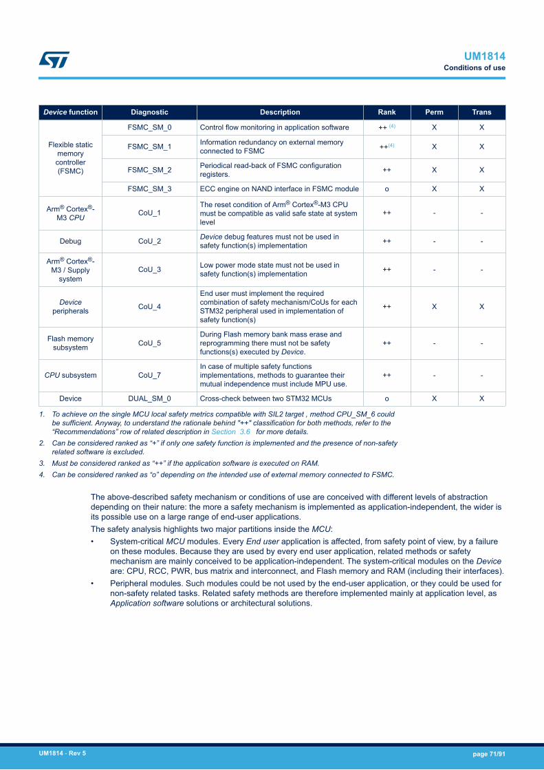
Device function Diagnostic Description Rank Perm Trans
Flexible staticmemorycontroller(FSMC)
FSMC_SM_0 Control flow monitoring in application software ++ (4) X X
FSMC_SM_1 Information redundancy on external memoryconnected to FSMC ++(4) X X
FSMC_SM_2 Periodical read-back of FSMC configurationregisters. ++ X X
FSMC_SM_3 ECC engine on NAND interface in FSMC module o X X
Arm® Cortex®-M3 CPU
CoU_1The reset condition of Arm® Cortex®-M3 CPUmust be compatible as valid safe state at systemlevel
++ - -
Debug CoU_2 Device debug features must not be used insafety function(s) implementation ++ - -
Arm® Cortex®-M3 / Supply
systemCoU_3 Low power mode state must not be used in
safety function(s) implementation ++ - -
Deviceperipherals CoU_4
End user must implement the requiredcombination of safety mechanism/CoUs for eachSTM32 peripheral used in implementation ofsafety function(s)
++ X X
Flash memorysubsystem CoU_5
During Flash memory bank mass erase andreprogramming there must not be safetyfunctions(s) executed by Device.
++ - -
CPU subsystem CoU_7In case of multiple safety functionsimplementations, methods to guarantee theirmutual independence must include MPU use.
++ - -
Device DUAL_SM_0 Cross-check between two STM32 MCUs o X X
1. To achieve on the single MCU local safety metrics compatible with SIL2 target , method CPU_SM_6 couldbe sufficient. Anyway, to understand the rationale behind "++" classification for both methods, refer to the“Recommendations” row of related description in Section 3.6 for more details.
2. Can be considered ranked as “+” if only one safety function is implemented and the presence of non-safetyrelated software is excluded.
3. Must be considered ranked as “++” if the application software is executed on RAM.4. Can be considered ranked as “o” depending on the intended use of external memory connected to FSMC.
The above-described safety mechanism or conditions of use are conceived with different levels of abstractiondepending on their nature: the more a safety mechanism is implemented as application-independent, the wider isits possible use on a large range of end-user applications.The safety analysis highlights two major partitions inside the MCU:• System-critical MCU modules. Every End user application is affected, from safety point of view, by a failure
on these modules. Because they are used by every end user application, related methods or safetymechanism are mainly conceived to be application-independent. The system-critical modules on the Deviceare: CPU, RCC, PWR, bus matrix and interconnect, and Flash memory and RAM (including their interfaces).
• Peripheral modules. Such modules could be not used by the end-user application, or they could be used fornon-safety related tasks. Related safety methods are therefore implemented mainly at application level, asApplication software solutions or architectural solutions.
UM1814Conditions of use
UM1814 - Rev 5 page 71/91
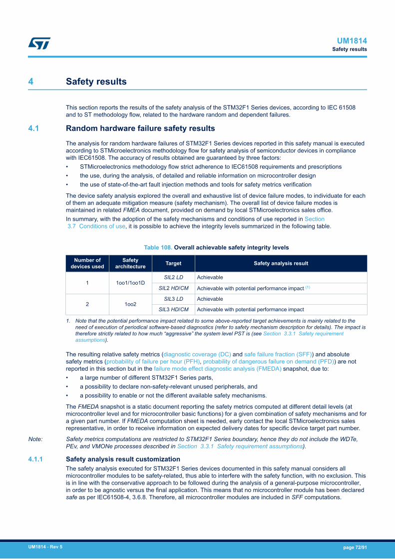
4 Safety results
This section reports the results of the safety analysis of the STM32F1 Series devices, according to IEC 61508and to ST methodology flow, related to the hardware random and dependent failures.
4.1 Random hardware failure safety results
The analysis for random hardware failures of STM32F1 Series devices reported in this safety manual is executedaccording to STMicroelectronics methodology flow for safety analysis of semiconductor devices in compliancewith IEC61508. The accuracy of results obtained are guaranteed by three factors:• STMicroelectronics methodology flow strict adherence to IEC61508 requirements and prescriptions• the use, during the analysis, of detailed and reliable information on microcontroller design• the use of state-of-the-art fault injection methods and tools for safety metrics verification
The device safety analysis explored the overall and exhaustive list of device failure modes, to individuate for eachof them an adequate mitigation measure (safety mechanism). The overall list of device failure modes ismaintained in related FMEA document, provided on demand by local STMicroelectronics sales office.In summary, with the adoption of the safety mechanisms and conditions of use reported in Section 3.7 Conditions of use, it is possible to achieve the integrity levels summarized in the following table.
Table 108. Overall achievable safety integrity levels
Number ofdevices used
Safetyarchitecture Target Safety analysis result
1 1oo1/1oo1DSIL2 LD Achievable
SIL2 HD/CM Achievable with potential performance impact (1)
2 1oo2SIL3 LD Achievable
SIL3 HD/CM Achievable with potential performance impact
1. Note that the potential performance impact related to some above-reported target achievements is mainly related to theneed of execution of periodical software-based diagnostics (refer to safety mechanism description for details). The impact istherefore strictly related to how much “aggressive” the system level PST is (see Section 3.3.1 Safety requirementassumptions).
The resulting relative safety metrics (diagnostic coverage (DC) and safe failure fraction (SFF)) and absolutesafety metrics (probability of failure per hour (PFH), probability of dangerous failure on demand (PFD)) are notreported in this section but in the failure mode effect diagnostic analysis (FMEDA) snapshot, due to:• a large number of different STM32F1 Series parts,• a possibility to declare non-safety-relevant unused peripherals, and• a possibility to enable or not the different available safety mechanisms.
The FMEDA snapshot is a static document reporting the safety metrics computed at different detail levels (atmicrocontroller level and for microcontroller basic functions) for a given combination of safety mechanisms and fora given part number. If FMEDA computation sheet is needed, early contact the local STMicroelectronics salesrepresentative, in order to receive information on expected delivery dates for specific device target part number.
Note: Safety metrics computations are restricted to STM32F1 Series boundary, hence they do not include the WDTe,PEv, and VMONe processes described in Section 3.3.1 Safety requirement assumptions).
4.1.1 Safety analysis result customizationThe safety analysis executed for STM32F1 Series devices documented in this safety manual considers allmicrocontroller modules to be safety-related, thus able to interfere with the safety function, with no exclusion. Thisis in line with the conservative approach to be followed during the analysis of a general-purpose microcontroller,in order to be agnostic versus the final application. This means that no microcontroller module has been declaredsafe as per IEC61508-4, 3.6.8. Therefore, all microcontroller modules are included in SFF computations.
UM1814Safety results
UM1814 - Rev 5 page 72/91

In actual End user applications, not all the STM32F1 Series parts or modules implement a safety function. Thathappens if:• The part is not used at all (disabled), or• The part implements functions that are not safety-related (for example, a GPIO line driving a power-on
signaling light on an electronic board).
Implementing safety mechanisms on such parts would be a useless effort for End user. The safety analysisresults can therefore be customized.End user can define a STM32F1 Series part as non-safety-related based on:• Collecting rationales and evidences that the part does not contribute to safety function.• Collecting rationales and evidences that the part does not interfere with the safety function during normal
operation, due to final system design decisions.• Fulfilling the general condition for the mitigation of intra-MCU interferences (see Table 1).
For a non-safety-related part, End user is allowed to:• Exclude the part from computing metrics to report in FMEDA, and• Not implement safety mechanisms as listed in Table 107. List of safety mechanisms.
With regard to SFF computation, this section complies with the no part / no effect definition as per IEC 61508‑4,3.6.13 / 3.6.14.
4.1.2 General requirements for freedom from interferences (FFI)A dedicated analysis has highlighted a list of general requirements to be followed in order to mitigate potentialinterferences between Device internal modules in case of internal failures (freedom from interferences, FFI).These precautions are integral part of the Device safety concept and they can play a relevant role when multiplemicrocontroller modules are declared as non-safety-related by End user as per Section 4.1.1 Safety analysisresult customization.End user must implement the safety mechanisms listed in Table 109 (implementation details in Section 3.6 Hardware and software diagnostics) regardless any evaluation of their contribution to safety metrics.
Table 109. List of general requirements for FFI
Diagnostic Description
FFI_SM_0 Unused peripheral disable
FFI_SM_1 Periodical read-back of interference avoidance registers
BUS_SM_0 Periodical software test for interconnections
NVIC_SM_0 Periodical read-back of configuration registers
NVIC_SM_1 Expected and unexpected interrupt check by application software
DMA_SM_0 Periodical read-back of configuration registers
DMA_SM_2 Information redundancy including sender or receiver identifier on data packet transferred via DMA (1)
DMA_SM_4 DMA transactions awareness(1)
GPIO_SM_0 Periodical read-back of configuration registers
1. To be implemented only if DMA is actually used
4.1.3 Notes on multiple-fault scenarioAccording to the requirements of IEC61508, the safety analysis for STM32F1 Series devices considered multiple-fault scenarios. Furthermore, following the spirit of ISO26262 (the reference and state-of-the-art standard norm forintegrated circuit safety analysis), the analysis investigated possible causes preventing the implemented safetymechanisms from being effective, in order to determine appropriate counter-measures. In the Multiple-faultprotection field, the tables in Section 3.6 Hardware and software diagnostics report the safety mechanismsrequired to properly manage a multiple-fault scenario, including mitigation measures against failures makingsafety mechanisms ineffective.It is strongly recommended that the safety concept includes such mitigation measures, and in particular forsystems operating during long periods, as they tend to accumulate errors.
UM1814Random hardware failure safety results
UM1814 - Rev 5 page 73/91

Indeed, fault accumulation issue has been taken into account during STM32F1 Series devices safety analysis.Another potential source of multiple error condition is the accumulation of permanent failures during power-offperiods. Indeed, if the end system is not powered, no safety mechanism are active and so able to early detect theinsurgence of such failures. To mitigate this potential issue, it is strongly recommended to execute all periodicsafety mechanism at each system power-up; this measure guarantees a fresh system start with a fault-freehardware. This recommendation is given for periodic safety mechanisms rated as "++" (highly recommended) inthe Device safety concept, and mainly for the most relevant ones in term of failure distribution: CPU_SM_0,FLASH_SM_0, RAM_SM_0. This startup execution is strongly recommended regardless the safety functionsmode of operations and/or the value of PST.
4.2 Analysis of dependent failures
The analysis of dependent failures is important for microcontroller and microprocessor devices. The mainsubclasses of dependent failures are CCFs. Their analysis is ruled by the IEC 61508:2 annex E that lists thedesign requirements to be verified to allow the use of on-chip redundancy for integrated circuits with one commonsemiconductor substrate.As there is no on-chip redundancy on STM32F1 Series devices, the CCF quantification through the βICcomputation method - as required by Annex E.1, item i - is not required. Note that, in the case of 1oo2 safetyarchitecture implementation, End user is required to evaluate the β and βD parameters (used in PFHcomputation) that reflect the common cause factors between the two channels.The Device architecture and structures can be potential sources of dependent failures. These are analyzed in thefollowing sections. The referred safety mechanisms are described in Section 3.6 Hardware and softwarediagnostics.
4.2.1 Power supplyPower supply is a potential source of dependent failures, because any alteration can simultaneously affect manymodules, leading to not-independent failures. The following safety mechanisms address and mitigate thosedependent failures:• VSUP_SM_1: detection of abnormal value of supply voltage;• VSUP_SM_2: the independent watchdog is different from the digital core of the MCU, and this diversity
helps to mitigate dependent failures related to the main supply alterations. As reported in VSUP_SM_2description, separate power supply for IWDG or/and the adoption of an external watchdog (CPU_SM_5)increase such diversity.
The adoption of such safety mechanisms is therefore highly recommended despite their minor contribution to thesafety metrics to reach the required safety integrity level. Refer to Section 3.6.18 Power controller (PWR) for thedetailed safety mechanism descriptions.
4.2.2 ClockSystem clocks are a potential source of dependent failures, because alterations in the clock characteristics(frequency, jitter) can affect many parts, leading to not-independent failures. The following safety mechanismsaddress and mitigate such dependent failures:• CLK_SM_1: the clock security system is able to detect hard alterations (stop) of system clock and activate
the adequate recovery actions.• CLK_SM_2: the independent watchdog has a dedicated clock source. The frequency alteration of the
system clock leads to the watchdog window violations by the triggering routine on the application software,leading to the MCU reset by watchdog.
The adoption of such safety mechanism is therefore highly recommended despite their minor contribution to thesafety metrics to reach the required safety integrity level. Refer to Section 3.6.19 Reset and clock controller(RCC) for detailed safety mechanisms description.
UM1814Analysis of dependent failures
UM1814 - Rev 5 page 74/91

4.2.3 DMAThe DMA function can be involved in data transfers operated by most of the peripherals. Failures of DMA caninterfere with the behavior of the system peripherals or application software, leading to dependent failures. Theadoption of the following safety mechanisms is therefore highly recommended (refer to Section 3.6.6 Directmemory access controller (DMA) for description):• DMA_SM_0• DMA_SM_1• DMA_SM_2
Note: Only DMA_SM_0 must be implemented if DMA is not used for data transfer.
4.2.4 Internal temperatureThe abnormal increase of the internal temperature is a potential source of dependent failures, as it can affectmany MCU parts. The following safety mechanism mitigates this potential effect (refer to Section 3.6.18 Powercontroller (PWR) for description):VSUP_SM_3: the internal temperature read and check allows the user to quickly detect potential risky conditionsbefore they lead to a series of internal failures.
UM1814Analysis of dependent failures
UM1814 - Rev 5 page 75/91

5 List of evidences
A safety case database stores all the information related to the safety analysis performed to derive the results andconclusions reported in this safety manual.The safety case database is composed of the following:• safety case with the full list of all safety-analysis-related documents• STMicroelectronics' internal FMEDA tool database for the computation of safety metrics, including estimated
and measured values• safety report, a document that describes in detail the safety analysis executed on STM32F1 Series devices
and the clause-by-clause compliance to IEC 61508• STMicroelectronics' internal fault injection campaign database including tool configuration and settings, fault
injection logs and results
As these materials contain STMicroelectronics' confidential information, they are only available for the purpose ofaudit and inspection by authorized bodies, without being published, which conforms to Note 2 of IEC 61508:2,7.4.9.7.
UM1814List of evidences
UM1814 - Rev 5 page 76/91

6 Change impact analysis for other safety standards
The safety analysis reported in this safety manual is executed according to the IEC 61508 safety norm. Thissection reports the outcome of a change impact analysis with respect to different safety standards. For each newsafety standard addressed, the following items are considered:• Differences in the suggested hardware architecture (architectural categories), and how to map to safety
architectures of IEC 61508.• Differences in the safety integrity level definitions and metrics computation methods, and how to recompute
and judge the safety performances of the devices according to the new standard.
The safety standards examined within this change impact analysis are:• ISO 13849-1:2015, ISO13849-2:2012 – Safety of machinery and Safety-related parts of control systems,• IEC 62061:2005+AMD1:2012+AMD2:2015 – Safety of machinery and Functional safety of safety-related
electrical, electronic and programmable electronic control systems,• IEC 61800-5-2:2016 –Adjustable speed electrical power drive systems – Part 5-2: Safety requirements –
Functional
6.1 ISO 13849-1:2015, ISO 13849-2:2012
ISO 13849-1 is a type B1 standard. It provides a guideline for the development of Safety-related parts ofmachinery control systems (SRP/CS) including programmable electronics, hardware and software.
6.1.1 ISO 13849 architectural categoriesISO 13849-1:2015 reports in section 4.4, Figure 4 a typical safety function diagrammatic presentation. Under theassumption that the compliant item as defined in section is used to implement the b (logic), the equivalence of theISO 13849 representation with the one in Section 3.2.1 is evident. The mapping of ISO 13849 architectures withthe one described in Section 3 is possible.ISO 13849-1:2015 in section §6 defines in details five different categories. The following table lists for eachcategory the possible implementation by one of the IEC 61508 compliant architectures described in this manual inSection 3 . It is worth to note that for each category, the achievable PL is decided by the specific values ofdiagnostic coverage (DC)avg and mean time to dangerous failure (MTTFd) (refer to Section 6.1.2 for details oncomputations).
UM1814Change impact analysis for other safety standards
UM1814 - Rev 5 page 77/91
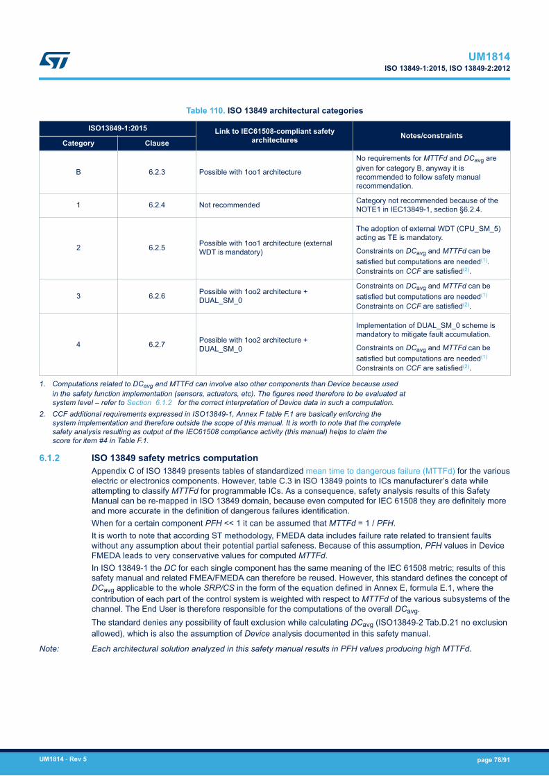
Table 110. ISO 13849 architectural categories
ISO13849-1:2015 Link to IEC61508-compliant safetyarchitectures Notes/constraints
Category Clause
B 6.2.3 Possible with 1oo1 architecture
No requirements for MTTFd and DCavg aregiven for category B, anyway it isrecommended to follow safety manualrecommendation.
1 6.2.4 Not recommended Category not recommended because of theNOTE1 in IEC13849-1, section §6.2.4.
2 6.2.5 Possible with 1oo1 architecture (externalWDT is mandatory)
The adoption of external WDT (CPU_SM_5)acting as TE is mandatory.
Constraints on DCavg and MTTFd can besatisfied but computations are needed(1).Constraints on CCF are satisfied(2).
3 6.2.6 Possible with 1oo2 architecture +DUAL_SM_0
Constraints on DCavg and MTTFd can besatisfied but computations are needed(1)
Constraints on CCF are satisfied(2).
4 6.2.7 Possible with 1oo2 architecture +DUAL_SM_0
Implementation of DUAL_SM_0 scheme ismandatory to mitigate fault accumulation.
Constraints on DCavg and MTTFd can besatisfied but computations are needed(1)
Constraints on CCF are satisfied(2).
1. Computations related to DCavg and MTTFd can involve also other components than Device because usedin the safety function implementation (sensors, actuators, etc). The figures need therefore to be evaluated atsystem level – refer to Section 6.1.2 for the correct interpretation of Device data in such a computation.
2. CCF additional requirements expressed in ISO13849-1, Annex F table F.1 are basically enforcing thesystem implementation and therefore outside the scope of this manual. It is worth to note that the completesafety analysis resulting as output of the IEC61508 compliance activity (this manual) helps to claim thescore for item #4 in Table F.1.
6.1.2 ISO 13849 safety metrics computationAppendix C of ISO 13849 presents tables of standardized mean time to dangerous failure (MTTFd) for the variouselectric or electronics components. However, table C.3 in ISO 13849 points to ICs manufacturer’s data whileattempting to classify MTTFd for programmable ICs. As a consequence, safety analysis results of this SafetyManual can be re-mapped in ISO 13849 domain, because even computed for IEC 61508 they are definitely moreand more accurate in the definition of dangerous failures identification.When for a certain component PFH << 1 it can be assumed that MTTFd = 1 / PFH.It is worth to note that according ST methodology, FMEDA data includes failure rate related to transient faultswithout any assumption about their potential partial safeness. Because of this assumption, PFH values in DeviceFMEDA leads to very conservative values for computed MTTFd.In ISO 13849-1 the DC for each single component has the same meaning of the IEC 61508 metric; results of thissafety manual and related FMEA/FMEDA can therefore be reused. However, this standard defines the concept ofDCavg applicable to the whole SRP/CS in the form of the equation defined in Annex E, formula E.1, where thecontribution of each part of the control system is weighted with respect to MTTFd of the various subsystems of thechannel. The End User is therefore responsible for the computations of the overall DCavg.The standard denies any possibility of fault exclusion while calculating DCavg (ISO13849-2 Tab.D.21 no exclusionallowed), which is also the assumption of Device analysis documented in this safety manual.
Note: Each architectural solution analyzed in this safety manual results in PFH values producing high MTTFd.
UM1814ISO 13849-1:2015, ISO 13849-2:2012
UM1814 - Rev 5 page 78/91

6.2 IEC 62061:2005+AMD1:2012+AMD2:2015
This standard is applicable in the specification, design and verification or validation of safety-related electricalcontrol systems (SRECS) of machines. SRECS is the electrical or electronics control system of the machinewhich failure could lead to reduction or loss of safety. SRECS implements a safety-related control function (SRCF)to prevent any increase of the risk.Because STM32xx has been classified as Type B according IEC61508 (refer to Section 3.2.2 ), it must beconsidered as a “complex component” in IEC62061 definition.
6.2.1 IEC 62061 architectural categoriesIEC 62061 defines a set of basic system architectures to be used for the design of safety-related electrical controlsystems (safety-related electrical control systems (SRECS)) implementing their SRCFs. The following table listsfor each system architecture the possible implementation/mapping by/to one of the IEC 61508 compliantarchitectures described in this manual in Section 3 .Safety metrics related to STM32xx MCU can be reused from IEC61508 analysis (refer to device FMEDA), whiletheir combination with the ones related to other devices included in the system is full responsibility of End user.
Table 111. IEC 62061 architectural categories
IEC 62061 Link to IEC61508-compliant safetyarchitectures Notes/constraints
Architecture Clause
A 6.7.8.2.2 Equivalent of 1oo1, with HFT = 0, nodiagnostic function(s) implemented. -
B 6.7.8.2.3Equivalent to 1oo2 with HFT = 1, a singlefailure does not lead to the loss of SRCF.
No diagnostic function(s) implemented.-
C 6.7.8.2.4 Equivalent of 1oo1 architecture. All requirements related to 1oo1 architecturemust be implemented.
D 6.7.8.2.5 Equivalent of 1oo2 architecture. All requirements related to 1oo2 architecturemust be implemented.
6.2.2 IEC 62061 safety metrics computationThe failure rate (λ) in T is the smaller proof test interval or the life time of the subsystem.As seen in ISO 13849, the approximation §6.7.8.2.1 NOTE2 is still considered valid, henceλ = 1 / MTTFd, where it is assumed that 1 >> λ x T.So, as PFHD = λD x 1h, so PFD = 1 / MTTFd.Safety analysis executed for STM32F1 Series devices according to IEC 61508 is more and more accurate for thedefinition of dangerous failure identifications that can be re-mapped in IEC 62061 domain. Thus, values of λ, PFHand SFF that are reported in the FMEDA (refer to Section 4 Safety results), are still valid and can be reused.For evaluation of CCF in basic architectures with HFT = 1, End user can rely to what reported in Section 4.2 Analysis of dependent failures, and to the guidelines included in IEC 61508:2010-6 Annex D.Alternatively, End user can apply the simplified approach from the standard (refer to Annex F) to calculate the βfactor value to be used in formulas for PFD.
UM1814IEC 62061:2005+AMD1:2012+AMD2:2015
UM1814 - Rev 5 page 79/91

6.3 IEC 61800-5-2:2016
The scope of this standard is the functional safety of adjustable speed electric drive systems.
6.3.1 IEC 61800 architectural categoriesBecause IEC 61800 definitions for HFT and for architectures are equivalent to the ones of IEC61508, theremapping is straightforward.The STM32xx MCU is considered as Type B for the consideration reported in Section 3.2.2 .
6.3.2 IEC 61800 safety metrics computationThe PFH of a safety function performed by PDS(SR) is evaluated by the application of IEC 61508-2. The stronglink with the norm IEC 61508 is reflected also by the adoption in IEC 61800-5-2 of the same relevant metrics PFH,and SFF. So, results of this safety manual (and related FMEA and FMEDA) can be re-mapped in IEC 61800domain.
UM1814IEC 61800-5-2:2016
UM1814 - Rev 5 page 80/91
Revision history
Table 112. Document revision history
Date Version Changes
06-Oct-2014 1 Initial release.
30-Jan-2015 2
Updated the applicability of the user manual to the microcontrollers of theSTM32F1 Series and to STM32-SafeSIL part number.
Updated:• Figure 1: STMicroelectronics product development process• Figure 16: Block diagram for IEC 62061 Cat. B• Figure 18: Block diagram for IEC 62061 Cat. D
14-Dec-2017 3 Changed confidentiality level from Public to ST Restricted.
01-Aug-2018 4
Changed document classification, from ST Restricted to Public.
Updated:• Section Introduction.• Section 1.1 Purpose and scope.• Section 1.2 Normative references.• Section 3.3 Safety analysis assumptions.• Section 3.6.8 Universal synchronous/asynchronous and low-power
universal asynchronous receiver/transmitter (USART).• Section 3.6.15 Advanced, general and low-power timers
TIM1/2/3/4/5/8/9/10/11/12/13/14/15/16/17.• Section 3.6.16 General-purpose input/output (GPIO) - port
A/B/C/D/E/F/G.• Section 3.7 Conditions of use.• Section 4 Safety results.• Section 5 List of evidences.
Removed:• 'Ygitech fRMethodology process' section.• Appendix A: Overview of fRMethodology• Appendix D: fRSTL_STM32L0_SIL2/3 product and its use in the
framework of this manual.
Added:• Section 3.2.3 Reference safety architectures - 1oo1.• Section 3.2.4 Reference safety architectures - 1oo2.• Section 3.6.27 HDMI-CEC module.• Section 3.6.25 Ethernet (ETH): media access control (MAC) with DMA
controller.
17-Feb-2020 5
Updated functional safety documentation framework.
Added:• Section 1.3 Reference documents.• Section 3.6.29 System.
Updated:• Section Introduction.• Section 1.2 Normative references.• Section 2 Device development process.• Section 3.2.2 Safety functions performed by Compliant item.• Section 3.2.4 Reference safety architectures - 1oo2.• Section 3.3.1 Safety requirement assumptions.• Section 3.6 Hardware and software diagnostics adding footnote.
UM1814
UM1814 - Rev 5 page 81/91

Date Version Changes
17-Feb-2020 5 (continued)
• Section 3.6.8 Universal synchronous/asynchronous and low-poweruniversal asynchronous receiver/transmitter (USART).
• Section 3.6.9 Inter-integrated circuit (I2C).• Section 3.6.12 Analog-to-digital converters (ADC).• Section 3.6.18 Power controller (PWR).• Section 3.7 Conditions of use.
UM1814
UM1814 - Rev 5 page 82/91

Glossary Application software within the software executed byDevice, the part that ensures functionality of End user'sapplication and integrates safety functions
CCF common cause failure
CM continuous mode
Compliant item any item subject to claim with respectto the clauses of IEC 61508 series of standards
COTS commercial off-the-shelf
CoU conditions of use
CPU central processing unit
CRC cyclic redundancy check
DC diagnostic coverage
Device depending on context, any single or all of theSTM32F1 Series silicon products
DMA direct memory access
DTI diagnostic test interval
ECM engine control module
ECU electronic control unit
End user individual person or company whointegrates Device in their application, such as anelectronic control board
EUC equipment under control
FIT failure in time
FMEA failure mode effect analysis
FMEDA failure mode effect diagnostic analysis
HD high-demand
HFT hardware fault tolerance
HW hardware
ITRS international technology roadmap forsemiconductors
LD low-demand
MCU microcontroller unit
MPU memory protection unit
MTBF mean time between failures
MTTFd mean time to dangerous failure
NA not applicable/available
PDS(SR) safety-related power drive system
PEc programmable electronics - core
PEd programmable electronics - diagnostic
PFD probability of dangerous failure on demand
PFH probability of failure per hour
PL performance level
PST process safety time
SFF safe failure fraction
SIL safety integrity level
SILCL safety integrity level claim limit
SRCF safety-related control function
SRECS safety-related electrical control systems
SRP/CS safety-related parts of machinery controlsystems
UM1814Glossary
UM1814 - Rev 5 page 83/91

Contents
1 About this document . . . . . . . . . . . . . . . . . . . . . . . . . . . . . . . . . . . . . . . . . . . . . . . . . . . . . . . . . . . . . .2
1.1 Purpose and scope . . . . . . . . . . . . . . . . . . . . . . . . . . . . . . . . . . . . . . . . . . . . . . . . . . . . . . . . . . . . . 2
1.2 Normative references . . . . . . . . . . . . . . . . . . . . . . . . . . . . . . . . . . . . . . . . . . . . . . . . . . . . . . . . . . . 2
1.3 Reference documents. . . . . . . . . . . . . . . . . . . . . . . . . . . . . . . . . . . . . . . . . . . . . . . . . . . . . . . . . . . 2
2 Device development process . . . . . . . . . . . . . . . . . . . . . . . . . . . . . . . . . . . . . . . . . . . . . . . . . . . . . .4
3 Reference safety architecture . . . . . . . . . . . . . . . . . . . . . . . . . . . . . . . . . . . . . . . . . . . . . . . . . . . . . .5
3.1 Safety architecture introduction . . . . . . . . . . . . . . . . . . . . . . . . . . . . . . . . . . . . . . . . . . . . . . . . . . . 5
3.2 Compliant item. . . . . . . . . . . . . . . . . . . . . . . . . . . . . . . . . . . . . . . . . . . . . . . . . . . . . . . . . . . . . . . . . 5
3.2.1 Definition of Compliant item . . . . . . . . . . . . . . . . . . . . . . . . . . . . . . . . . . . . . . . . . . . . . . . . 5
3.2.2 Safety functions performed by Compliant item . . . . . . . . . . . . . . . . . . . . . . . . . . . . . . . . . . 5
3.2.3 Reference safety architectures - 1oo1. . . . . . . . . . . . . . . . . . . . . . . . . . . . . . . . . . . . . . . . . 6
3.2.4 Reference safety architectures - 1oo2. . . . . . . . . . . . . . . . . . . . . . . . . . . . . . . . . . . . . . . . . 7
3.3 Safety analysis assumptions . . . . . . . . . . . . . . . . . . . . . . . . . . . . . . . . . . . . . . . . . . . . . . . . . . . . . 8
3.3.1 Safety requirement assumptions . . . . . . . . . . . . . . . . . . . . . . . . . . . . . . . . . . . . . . . . . . . . . 8
3.4 Electrical specifications and environment limits . . . . . . . . . . . . . . . . . . . . . . . . . . . . . . . . . . . . . 9
3.5 Systematic safety integrity . . . . . . . . . . . . . . . . . . . . . . . . . . . . . . . . . . . . . . . . . . . . . . . . . . . . . . . 9
3.6 Hardware and software diagnostics . . . . . . . . . . . . . . . . . . . . . . . . . . . . . . . . . . . . . . . . . . . . . . . 9
3.6.1 Arm® Cortex®-M3 CPU . . . . . . . . . . . . . . . . . . . . . . . . . . . . . . . . . . . . . . . . . . . . . . . . . . . 11
3.6.2 Embedded Flash memory . . . . . . . . . . . . . . . . . . . . . . . . . . . . . . . . . . . . . . . . . . . . . . . . . 16
3.6.3 Embedded SRAM . . . . . . . . . . . . . . . . . . . . . . . . . . . . . . . . . . . . . . . . . . . . . . . . . . . . . . . 21
3.6.4 System bus architecture/peripherals interconnect matrix . . . . . . . . . . . . . . . . . . . . . . . . . 24
3.6.5 EXTI controller . . . . . . . . . . . . . . . . . . . . . . . . . . . . . . . . . . . . . . . . . . . . . . . . . . . . . . . . . 26
3.6.6 Direct memory access controller (DMA) . . . . . . . . . . . . . . . . . . . . . . . . . . . . . . . . . . . . . . 27
3.6.7 Controller area network (bxCAN) . . . . . . . . . . . . . . . . . . . . . . . . . . . . . . . . . . . . . . . . . . . 30
3.6.8 Universal synchronous/asynchronous and low-power universal asynchronous receiver/transmitter (USART) . . . . . . . . . . . . . . . . . . . . . . . . . . . . . . . . . . . . . . . . . . . . . . . . . . . . . 32
3.6.9 Inter-integrated circuit (I2C). . . . . . . . . . . . . . . . . . . . . . . . . . . . . . . . . . . . . . . . . . . . . . . . 34
3.6.10 Serial peripheral interface (SPI) . . . . . . . . . . . . . . . . . . . . . . . . . . . . . . . . . . . . . . . . . . . . 37
3.6.11 USB on-the-go full-speed (OTG_FS) . . . . . . . . . . . . . . . . . . . . . . . . . . . . . . . . . . . . . . . . 39
3.6.12 Analog-to-digital converters (ADC) . . . . . . . . . . . . . . . . . . . . . . . . . . . . . . . . . . . . . . . . . . 41
UM1814Contents
UM1814 - Rev 5 page 84/91

3.6.13 Digital-to-analog converter (DAC) . . . . . . . . . . . . . . . . . . . . . . . . . . . . . . . . . . . . . . . . . . . 44
3.6.14 Basic timers TIM 6/7 . . . . . . . . . . . . . . . . . . . . . . . . . . . . . . . . . . . . . . . . . . . . . . . . . . . . . 45
3.6.15 Advanced, general and low-power timers TIM1/2/3/4/5/8/9/10/11/12/13/14/15/16/17 . . . . 46
3.6.16 General-purpose input/output (GPIO) - port A/B/C/D/E/F/G . . . . . . . . . . . . . . . . . . . . . . . 48
3.6.17 Real-time clock module (RTC) . . . . . . . . . . . . . . . . . . . . . . . . . . . . . . . . . . . . . . . . . . . . . 50
3.6.18 Power controller (PWR) . . . . . . . . . . . . . . . . . . . . . . . . . . . . . . . . . . . . . . . . . . . . . . . . . . 52
3.6.19 Reset and clock controller (RCC) . . . . . . . . . . . . . . . . . . . . . . . . . . . . . . . . . . . . . . . . . . . 54
3.6.20 Independent and system window watchdogs (IWDG and WWDG) . . . . . . . . . . . . . . . . . . 56
3.6.21 Debug support (DBG) . . . . . . . . . . . . . . . . . . . . . . . . . . . . . . . . . . . . . . . . . . . . . . . . . . . . 57
3.6.22 Cyclic redundancy-check module (CRC). . . . . . . . . . . . . . . . . . . . . . . . . . . . . . . . . . . . . . 57
3.6.23 System configuration controller (SYSCFG) . . . . . . . . . . . . . . . . . . . . . . . . . . . . . . . . . . . . 58
3.6.24 Secure digital input/output interface (SDIO) . . . . . . . . . . . . . . . . . . . . . . . . . . . . . . . . . . . 59
3.6.25 Ethernet (ETH): media access control (MAC) with DMA controller . . . . . . . . . . . . . . . . . . 60
3.6.26 Flexible static memory controller (FSMC) . . . . . . . . . . . . . . . . . . . . . . . . . . . . . . . . . . . . . 62
3.6.27 HDMI-CEC module . . . . . . . . . . . . . . . . . . . . . . . . . . . . . . . . . . . . . . . . . . . . . . . . . . . . . . 64
3.6.28 Disable and periodic cross-check of unintentional activation of unused peripherals . . . . . 65
3.6.29 System . . . . . . . . . . . . . . . . . . . . . . . . . . . . . . . . . . . . . . . . . . . . . . . . . . . . . . . . . . . . . . . 66
3.7 Conditions of use. . . . . . . . . . . . . . . . . . . . . . . . . . . . . . . . . . . . . . . . . . . . . . . . . . . . . . . . . . . . . . 67
4 Safety results. . . . . . . . . . . . . . . . . . . . . . . . . . . . . . . . . . . . . . . . . . . . . . . . . . . . . . . . . . . . . . . . . . . . .72
4.1 Random hardware failure safety results . . . . . . . . . . . . . . . . . . . . . . . . . . . . . . . . . . . . . . . . . . . 72
4.1.1 Safety analysis result customization . . . . . . . . . . . . . . . . . . . . . . . . . . . . . . . . . . . . . . . . . 72
4.1.2 General requirements for freedom from interferences (FFI) . . . . . . . . . . . . . . . . . . . . . . . 73
4.1.3 Notes on multiple-fault scenario . . . . . . . . . . . . . . . . . . . . . . . . . . . . . . . . . . . . . . . . . . . . 73
4.2 Analysis of dependent failures. . . . . . . . . . . . . . . . . . . . . . . . . . . . . . . . . . . . . . . . . . . . . . . . . . . 74
4.2.1 Power supply . . . . . . . . . . . . . . . . . . . . . . . . . . . . . . . . . . . . . . . . . . . . . . . . . . . . . . . . . . 74
4.2.2 Clock. . . . . . . . . . . . . . . . . . . . . . . . . . . . . . . . . . . . . . . . . . . . . . . . . . . . . . . . . . . . . . . . . 74
4.2.3 DMA . . . . . . . . . . . . . . . . . . . . . . . . . . . . . . . . . . . . . . . . . . . . . . . . . . . . . . . . . . . . . . . . . 75
4.2.4 Internal temperature . . . . . . . . . . . . . . . . . . . . . . . . . . . . . . . . . . . . . . . . . . . . . . . . . . . . . 75
5 List of evidences . . . . . . . . . . . . . . . . . . . . . . . . . . . . . . . . . . . . . . . . . . . . . . . . . . . . . . . . . . . . . . . . .76
6 Change impact analysis for other safety standards. . . . . . . . . . . . . . . . . . . . . . . . . . . . . . . .77
6.1 ISO 13849-1:2015, ISO 13849-2:2012. . . . . . . . . . . . . . . . . . . . . . . . . . . . . . . . . . . . . . . . . . . . 77
6.1.1 ISO 13849 architectural categories . . . . . . . . . . . . . . . . . . . . . . . . . . . . . . . . . . . . . . . . . . 77
UM1814Contents
UM1814 - Rev 5 page 85/91

6.1.2 ISO 13849 safety metrics computation . . . . . . . . . . . . . . . . . . . . . . . . . . . . . . . . . . . . . . . 78
6.2 IEC 62061:2005+AMD1:2012+AMD2:2015. . . . . . . . . . . . . . . . . . . . . . . . . . . . . . . . . . . . . . . . 79
6.2.1 IEC 62061 architectural categories . . . . . . . . . . . . . . . . . . . . . . . . . . . . . . . . . . . . . . . . . . 79
6.2.2 IEC 62061 safety metrics computation . . . . . . . . . . . . . . . . . . . . . . . . . . . . . . . . . . . . . . . 79
6.3 IEC 61800-5-2:2016 . . . . . . . . . . . . . . . . . . . . . . . . . . . . . . . . . . . . . . . . . . . . . . . . . . . . . . . . . . . 80
6.3.1 IEC 61800 architectural categories . . . . . . . . . . . . . . . . . . . . . . . . . . . . . . . . . . . . . . . . . . 80
6.3.2 IEC 61800 safety metrics computation . . . . . . . . . . . . . . . . . . . . . . . . . . . . . . . . . . . . . . . 80
Revision history . . . . . . . . . . . . . . . . . . . . . . . . . . . . . . . . . . . . . . . . . . . . . . . . . . . . . . . . . . . . . . . . . . . . . . .81
Glossary . . . . . . . . . . . . . . . . . . . . . . . . . . . . . . . . . . . . . . . . . . . . . . . . . . . . . . . . . . . . . . . . . . . . . . . . . . . . . .83
UM1814Contents
UM1814 - Rev 5 page 86/91

List of tablesTable 1. Document sections versus IEC 61508-2 Annex D safety requirements . . . . . . . . . . . . . . . . . . . . . . . . . . . . . . . 2Table 2. SS1 and SS2 safe state details . . . . . . . . . . . . . . . . . . . . . . . . . . . . . . . . . . . . . . . . . . . . . . . . . . . . . . . . . . 9Table 3. CPU_SM_0. . . . . . . . . . . . . . . . . . . . . . . . . . . . . . . . . . . . . . . . . . . . . . . . . . . . . . . . . . . . . . . . . . . . . . . 11Table 4. CPU_SM_1. . . . . . . . . . . . . . . . . . . . . . . . . . . . . . . . . . . . . . . . . . . . . . . . . . . . . . . . . . . . . . . . . . . . . . . 12Table 5. CPU_SM_2. . . . . . . . . . . . . . . . . . . . . . . . . . . . . . . . . . . . . . . . . . . . . . . . . . . . . . . . . . . . . . . . . . . . . . . 13Table 6. CPU_SM_3. . . . . . . . . . . . . . . . . . . . . . . . . . . . . . . . . . . . . . . . . . . . . . . . . . . . . . . . . . . . . . . . . . . . . . . 13Table 7. CPU_SM_4. . . . . . . . . . . . . . . . . . . . . . . . . . . . . . . . . . . . . . . . . . . . . . . . . . . . . . . . . . . . . . . . . . . . . . . 14Table 8. CPU_SM_5. . . . . . . . . . . . . . . . . . . . . . . . . . . . . . . . . . . . . . . . . . . . . . . . . . . . . . . . . . . . . . . . . . . . . . . 15Table 9. CPU_SM_6. . . . . . . . . . . . . . . . . . . . . . . . . . . . . . . . . . . . . . . . . . . . . . . . . . . . . . . . . . . . . . . . . . . . . . . 15Table 10. CPU_SM_7. . . . . . . . . . . . . . . . . . . . . . . . . . . . . . . . . . . . . . . . . . . . . . . . . . . . . . . . . . . . . . . . . . . . . . . 16Table 11. MPU_SM_0 . . . . . . . . . . . . . . . . . . . . . . . . . . . . . . . . . . . . . . . . . . . . . . . . . . . . . . . . . . . . . . . . . . . . . . 16Table 12. FLASH_SM_0 . . . . . . . . . . . . . . . . . . . . . . . . . . . . . . . . . . . . . . . . . . . . . . . . . . . . . . . . . . . . . . . . . . . . . 17Table 13. FLASH_SM_1 . . . . . . . . . . . . . . . . . . . . . . . . . . . . . . . . . . . . . . . . . . . . . . . . . . . . . . . . . . . . . . . . . . . . . 17Table 14. FLASH_SM_2 . . . . . . . . . . . . . . . . . . . . . . . . . . . . . . . . . . . . . . . . . . . . . . . . . . . . . . . . . . . . . . . . . . . . . 18Table 15. FLASH_SM_3 . . . . . . . . . . . . . . . . . . . . . . . . . . . . . . . . . . . . . . . . . . . . . . . . . . . . . . . . . . . . . . . . . . . . . 18Table 16. FLASH_SM_4 . . . . . . . . . . . . . . . . . . . . . . . . . . . . . . . . . . . . . . . . . . . . . . . . . . . . . . . . . . . . . . . . . . . . . 19Table 17. FLASH_SM_5 . . . . . . . . . . . . . . . . . . . . . . . . . . . . . . . . . . . . . . . . . . . . . . . . . . . . . . . . . . . . . . . . . . . . . 19Table 18. FLASH_SM_6 . . . . . . . . . . . . . . . . . . . . . . . . . . . . . . . . . . . . . . . . . . . . . . . . . . . . . . . . . . . . . . . . . . . . . 19Table 19. FLASH_SM_8 . . . . . . . . . . . . . . . . . . . . . . . . . . . . . . . . . . . . . . . . . . . . . . . . . . . . . . . . . . . . . . . . . . . . . 20Table 20. RAM_SM_0 . . . . . . . . . . . . . . . . . . . . . . . . . . . . . . . . . . . . . . . . . . . . . . . . . . . . . . . . . . . . . . . . . . . . . . 21Table 21. RAM_SM_2 . . . . . . . . . . . . . . . . . . . . . . . . . . . . . . . . . . . . . . . . . . . . . . . . . . . . . . . . . . . . . . . . . . . . . . 22Table 22. RAM_SM_3 . . . . . . . . . . . . . . . . . . . . . . . . . . . . . . . . . . . . . . . . . . . . . . . . . . . . . . . . . . . . . . . . . . . . . . 22Table 23. RAM_SM_4 . . . . . . . . . . . . . . . . . . . . . . . . . . . . . . . . . . . . . . . . . . . . . . . . . . . . . . . . . . . . . . . . . . . . . . 23Table 24. RAM_SM_5 . . . . . . . . . . . . . . . . . . . . . . . . . . . . . . . . . . . . . . . . . . . . . . . . . . . . . . . . . . . . . . . . . . . . . . 23Table 25. BUS_SM_0. . . . . . . . . . . . . . . . . . . . . . . . . . . . . . . . . . . . . . . . . . . . . . . . . . . . . . . . . . . . . . . . . . . . . . . 24Table 26. BUS_SM_1. . . . . . . . . . . . . . . . . . . . . . . . . . . . . . . . . . . . . . . . . . . . . . . . . . . . . . . . . . . . . . . . . . . . . . . 24Table 27. LOCK_SM_0. . . . . . . . . . . . . . . . . . . . . . . . . . . . . . . . . . . . . . . . . . . . . . . . . . . . . . . . . . . . . . . . . . . . . . 25Table 28. NVIC_SM_0 . . . . . . . . . . . . . . . . . . . . . . . . . . . . . . . . . . . . . . . . . . . . . . . . . . . . . . . . . . . . . . . . . . . . . . 26Table 29. NVIC_SM_1 . . . . . . . . . . . . . . . . . . . . . . . . . . . . . . . . . . . . . . . . . . . . . . . . . . . . . . . . . . . . . . . . . . . . . . 27Table 30. DMA_SM_0 . . . . . . . . . . . . . . . . . . . . . . . . . . . . . . . . . . . . . . . . . . . . . . . . . . . . . . . . . . . . . . . . . . . . . . 27Table 31. DMA_SM_1 . . . . . . . . . . . . . . . . . . . . . . . . . . . . . . . . . . . . . . . . . . . . . . . . . . . . . . . . . . . . . . . . . . . . . . 28Table 32. DMA_SM_2 . . . . . . . . . . . . . . . . . . . . . . . . . . . . . . . . . . . . . . . . . . . . . . . . . . . . . . . . . . . . . . . . . . . . . . 28Table 33. DMA_SM_3 . . . . . . . . . . . . . . . . . . . . . . . . . . . . . . . . . . . . . . . . . . . . . . . . . . . . . . . . . . . . . . . . . . . . . . 29Table 34. DMA_SM_4 . . . . . . . . . . . . . . . . . . . . . . . . . . . . . . . . . . . . . . . . . . . . . . . . . . . . . . . . . . . . . . . . . . . . . . 29Table 35. CAN_SM_0. . . . . . . . . . . . . . . . . . . . . . . . . . . . . . . . . . . . . . . . . . . . . . . . . . . . . . . . . . . . . . . . . . . . . . . 30Table 36. CAN_SM_1. . . . . . . . . . . . . . . . . . . . . . . . . . . . . . . . . . . . . . . . . . . . . . . . . . . . . . . . . . . . . . . . . . . . . . . 31Table 37. CAN_SM_2. . . . . . . . . . . . . . . . . . . . . . . . . . . . . . . . . . . . . . . . . . . . . . . . . . . . . . . . . . . . . . . . . . . . . . . 32Table 38. UART_SM_0. . . . . . . . . . . . . . . . . . . . . . . . . . . . . . . . . . . . . . . . . . . . . . . . . . . . . . . . . . . . . . . . . . . . . . 32Table 39. UART_SM_1. . . . . . . . . . . . . . . . . . . . . . . . . . . . . . . . . . . . . . . . . . . . . . . . . . . . . . . . . . . . . . . . . . . . . . 33Table 40. UART_SM_2. . . . . . . . . . . . . . . . . . . . . . . . . . . . . . . . . . . . . . . . . . . . . . . . . . . . . . . . . . . . . . . . . . . . . . 33Table 41. UART_SM_3. . . . . . . . . . . . . . . . . . . . . . . . . . . . . . . . . . . . . . . . . . . . . . . . . . . . . . . . . . . . . . . . . . . . . . 34Table 42. IIC_SM_0 . . . . . . . . . . . . . . . . . . . . . . . . . . . . . . . . . . . . . . . . . . . . . . . . . . . . . . . . . . . . . . . . . . . . . . . . 35Table 43. IIC_SM_1 . . . . . . . . . . . . . . . . . . . . . . . . . . . . . . . . . . . . . . . . . . . . . . . . . . . . . . . . . . . . . . . . . . . . . . . . 35Table 44. IIC_SM_2 . . . . . . . . . . . . . . . . . . . . . . . . . . . . . . . . . . . . . . . . . . . . . . . . . . . . . . . . . . . . . . . . . . . . . . . . 35Table 45. IIC_SM_3 . . . . . . . . . . . . . . . . . . . . . . . . . . . . . . . . . . . . . . . . . . . . . . . . . . . . . . . . . . . . . . . . . . . . . . . . 36Table 46. IIC_SM_4 . . . . . . . . . . . . . . . . . . . . . . . . . . . . . . . . . . . . . . . . . . . . . . . . . . . . . . . . . . . . . . . . . . . . . . . . 37Table 47. SPI_SM_0 . . . . . . . . . . . . . . . . . . . . . . . . . . . . . . . . . . . . . . . . . . . . . . . . . . . . . . . . . . . . . . . . . . . . . . . 37Table 48. SPI_SM_1 . . . . . . . . . . . . . . . . . . . . . . . . . . . . . . . . . . . . . . . . . . . . . . . . . . . . . . . . . . . . . . . . . . . . . . . 37Table 49. SPI_SM_2 . . . . . . . . . . . . . . . . . . . . . . . . . . . . . . . . . . . . . . . . . . . . . . . . . . . . . . . . . . . . . . . . . . . . . . . 38Table 50. SPI_SM_3 . . . . . . . . . . . . . . . . . . . . . . . . . . . . . . . . . . . . . . . . . . . . . . . . . . . . . . . . . . . . . . . . . . . . . . . 38Table 51. SPI_SM_4 . . . . . . . . . . . . . . . . . . . . . . . . . . . . . . . . . . . . . . . . . . . . . . . . . . . . . . . . . . . . . . . . . . . . . . . 39Table 52. USB_SM_0. . . . . . . . . . . . . . . . . . . . . . . . . . . . . . . . . . . . . . . . . . . . . . . . . . . . . . . . . . . . . . . . . . . . . . . 40
UM1814List of tables
UM1814 - Rev 5 page 87/91

Table 53. USB_SM_1. . . . . . . . . . . . . . . . . . . . . . . . . . . . . . . . . . . . . . . . . . . . . . . . . . . . . . . . . . . . . . . . . . . . . . . 40Table 54. USB_SM_2. . . . . . . . . . . . . . . . . . . . . . . . . . . . . . . . . . . . . . . . . . . . . . . . . . . . . . . . . . . . . . . . . . . . . . . 41Table 55. USB_SM_3. . . . . . . . . . . . . . . . . . . . . . . . . . . . . . . . . . . . . . . . . . . . . . . . . . . . . . . . . . . . . . . . . . . . . . . 41Table 56. ADC_SM_0. . . . . . . . . . . . . . . . . . . . . . . . . . . . . . . . . . . . . . . . . . . . . . . . . . . . . . . . . . . . . . . . . . . . . . . 42Table 57. ADC_SM_1. . . . . . . . . . . . . . . . . . . . . . . . . . . . . . . . . . . . . . . . . . . . . . . . . . . . . . . . . . . . . . . . . . . . . . . 42Table 58. ADC_SM_2. . . . . . . . . . . . . . . . . . . . . . . . . . . . . . . . . . . . . . . . . . . . . . . . . . . . . . . . . . . . . . . . . . . . . . . 43Table 59. ADC_SM_3. . . . . . . . . . . . . . . . . . . . . . . . . . . . . . . . . . . . . . . . . . . . . . . . . . . . . . . . . . . . . . . . . . . . . . . 43Table 60. ADC_SM_4. . . . . . . . . . . . . . . . . . . . . . . . . . . . . . . . . . . . . . . . . . . . . . . . . . . . . . . . . . . . . . . . . . . . . . . 44Table 61. DAC_SM_0. . . . . . . . . . . . . . . . . . . . . . . . . . . . . . . . . . . . . . . . . . . . . . . . . . . . . . . . . . . . . . . . . . . . . . . 44Table 62. DAC_SM_1. . . . . . . . . . . . . . . . . . . . . . . . . . . . . . . . . . . . . . . . . . . . . . . . . . . . . . . . . . . . . . . . . . . . . . . 44Table 63. GTIM_SM_0 . . . . . . . . . . . . . . . . . . . . . . . . . . . . . . . . . . . . . . . . . . . . . . . . . . . . . . . . . . . . . . . . . . . . . . 45Table 64. GTIM_SM_1 . . . . . . . . . . . . . . . . . . . . . . . . . . . . . . . . . . . . . . . . . . . . . . . . . . . . . . . . . . . . . . . . . . . . . . 46Table 65. ATIM_SM_0 . . . . . . . . . . . . . . . . . . . . . . . . . . . . . . . . . . . . . . . . . . . . . . . . . . . . . . . . . . . . . . . . . . . . . . 46Table 66. ATIM_SM_1 . . . . . . . . . . . . . . . . . . . . . . . . . . . . . . . . . . . . . . . . . . . . . . . . . . . . . . . . . . . . . . . . . . . . . . 47Table 67. ATIM_SM_2 . . . . . . . . . . . . . . . . . . . . . . . . . . . . . . . . . . . . . . . . . . . . . . . . . . . . . . . . . . . . . . . . . . . . . . 47Table 68. ATIM_SM_3 . . . . . . . . . . . . . . . . . . . . . . . . . . . . . . . . . . . . . . . . . . . . . . . . . . . . . . . . . . . . . . . . . . . . . . 48Table 69. ATIM_SM_4 . . . . . . . . . . . . . . . . . . . . . . . . . . . . . . . . . . . . . . . . . . . . . . . . . . . . . . . . . . . . . . . . . . . . . . 48Table 70. GPIO_SM_0 . . . . . . . . . . . . . . . . . . . . . . . . . . . . . . . . . . . . . . . . . . . . . . . . . . . . . . . . . . . . . . . . . . . . . . 49Table 71. GPIO_SM_1 . . . . . . . . . . . . . . . . . . . . . . . . . . . . . . . . . . . . . . . . . . . . . . . . . . . . . . . . . . . . . . . . . . . . . . 49Table 72. GPIO_SM_2 . . . . . . . . . . . . . . . . . . . . . . . . . . . . . . . . . . . . . . . . . . . . . . . . . . . . . . . . . . . . . . . . . . . . . . 49Table 73. GPIO_SM_3 . . . . . . . . . . . . . . . . . . . . . . . . . . . . . . . . . . . . . . . . . . . . . . . . . . . . . . . . . . . . . . . . . . . . . . 50Table 74. RTC_SM_0 . . . . . . . . . . . . . . . . . . . . . . . . . . . . . . . . . . . . . . . . . . . . . . . . . . . . . . . . . . . . . . . . . . . . . . . 51Table 75. RTC_SM_1 . . . . . . . . . . . . . . . . . . . . . . . . . . . . . . . . . . . . . . . . . . . . . . . . . . . . . . . . . . . . . . . . . . . . . . . 51Table 76. RTC_SM_2 . . . . . . . . . . . . . . . . . . . . . . . . . . . . . . . . . . . . . . . . . . . . . . . . . . . . . . . . . . . . . . . . . . . . . . . 52Table 77. RTC_SM_3 . . . . . . . . . . . . . . . . . . . . . . . . . . . . . . . . . . . . . . . . . . . . . . . . . . . . . . . . . . . . . . . . . . . . . . . 52Table 78. VSUP_SM_0. . . . . . . . . . . . . . . . . . . . . . . . . . . . . . . . . . . . . . . . . . . . . . . . . . . . . . . . . . . . . . . . . . . . . . 53Table 79. VSUP_SM_1. . . . . . . . . . . . . . . . . . . . . . . . . . . . . . . . . . . . . . . . . . . . . . . . . . . . . . . . . . . . . . . . . . . . . . 53Table 80. VSUP_SM_2. . . . . . . . . . . . . . . . . . . . . . . . . . . . . . . . . . . . . . . . . . . . . . . . . . . . . . . . . . . . . . . . . . . . . . 54Table 81. VSUP_SM_3. . . . . . . . . . . . . . . . . . . . . . . . . . . . . . . . . . . . . . . . . . . . . . . . . . . . . . . . . . . . . . . . . . . . . . 54Table 82. CLK_SM_0 . . . . . . . . . . . . . . . . . . . . . . . . . . . . . . . . . . . . . . . . . . . . . . . . . . . . . . . . . . . . . . . . . . . . . . . 55Table 83. CLK_SM_1 . . . . . . . . . . . . . . . . . . . . . . . . . . . . . . . . . . . . . . . . . . . . . . . . . . . . . . . . . . . . . . . . . . . . . . . 55Table 84. CLK_SM_2 . . . . . . . . . . . . . . . . . . . . . . . . . . . . . . . . . . . . . . . . . . . . . . . . . . . . . . . . . . . . . . . . . . . . . . . 56Table 85. WDG_SM_0 . . . . . . . . . . . . . . . . . . . . . . . . . . . . . . . . . . . . . . . . . . . . . . . . . . . . . . . . . . . . . . . . . . . . . . 56Table 86. WDG_SM_1 . . . . . . . . . . . . . . . . . . . . . . . . . . . . . . . . . . . . . . . . . . . . . . . . . . . . . . . . . . . . . . . . . . . . . . 57Table 87. DBG_SM_0. . . . . . . . . . . . . . . . . . . . . . . . . . . . . . . . . . . . . . . . . . . . . . . . . . . . . . . . . . . . . . . . . . . . . . . 57Table 88. CRC_SM_0. . . . . . . . . . . . . . . . . . . . . . . . . . . . . . . . . . . . . . . . . . . . . . . . . . . . . . . . . . . . . . . . . . . . . . . 58Table 89. SYSCFG_SM_0 . . . . . . . . . . . . . . . . . . . . . . . . . . . . . . . . . . . . . . . . . . . . . . . . . . . . . . . . . . . . . . . . . . . 58Table 90. DIAG_SM_0 . . . . . . . . . . . . . . . . . . . . . . . . . . . . . . . . . . . . . . . . . . . . . . . . . . . . . . . . . . . . . . . . . . . . . . 59Table 91. SDIO_SM_0 . . . . . . . . . . . . . . . . . . . . . . . . . . . . . . . . . . . . . . . . . . . . . . . . . . . . . . . . . . . . . . . . . . . . . . 59Table 92. SDIO_SM_1 . . . . . . . . . . . . . . . . . . . . . . . . . . . . . . . . . . . . . . . . . . . . . . . . . . . . . . . . . . . . . . . . . . . . . . 59Table 93. SDIO_SM_2 . . . . . . . . . . . . . . . . . . . . . . . . . . . . . . . . . . . . . . . . . . . . . . . . . . . . . . . . . . . . . . . . . . . . . . 60Table 94. ETH_SM_0 . . . . . . . . . . . . . . . . . . . . . . . . . . . . . . . . . . . . . . . . . . . . . . . . . . . . . . . . . . . . . . . . . . . . . . . 60Table 95. ETH_SM_1 . . . . . . . . . . . . . . . . . . . . . . . . . . . . . . . . . . . . . . . . . . . . . . . . . . . . . . . . . . . . . . . . . . . . . . . 61Table 96. ETH_SM_2 . . . . . . . . . . . . . . . . . . . . . . . . . . . . . . . . . . . . . . . . . . . . . . . . . . . . . . . . . . . . . . . . . . . . . . . 61Table 97. FSMC_SM_0 . . . . . . . . . . . . . . . . . . . . . . . . . . . . . . . . . . . . . . . . . . . . . . . . . . . . . . . . . . . . . . . . . . . . . 62Table 98. FSMC_SM_1 . . . . . . . . . . . . . . . . . . . . . . . . . . . . . . . . . . . . . . . . . . . . . . . . . . . . . . . . . . . . . . . . . . . . . 63Table 99. FSMC_SM_2 . . . . . . . . . . . . . . . . . . . . . . . . . . . . . . . . . . . . . . . . . . . . . . . . . . . . . . . . . . . . . . . . . . . . . 63Table 100. FSMC_SM_3 . . . . . . . . . . . . . . . . . . . . . . . . . . . . . . . . . . . . . . . . . . . . . . . . . . . . . . . . . . . . . . . . . . . . . 64Table 101. HDMI_SM_0 . . . . . . . . . . . . . . . . . . . . . . . . . . . . . . . . . . . . . . . . . . . . . . . . . . . . . . . . . . . . . . . . . . . . . . 64Table 102. HDMI_SM_1 . . . . . . . . . . . . . . . . . . . . . . . . . . . . . . . . . . . . . . . . . . . . . . . . . . . . . . . . . . . . . . . . . . . . . . 64Table 103. HDMI_SM_2 . . . . . . . . . . . . . . . . . . . . . . . . . . . . . . . . . . . . . . . . . . . . . . . . . . . . . . . . . . . . . . . . . . . . . . 65Table 104. FFI_SM_0. . . . . . . . . . . . . . . . . . . . . . . . . . . . . . . . . . . . . . . . . . . . . . . . . . . . . . . . . . . . . . . . . . . . . . . . 65Table 105. FFI_SM_1. . . . . . . . . . . . . . . . . . . . . . . . . . . . . . . . . . . . . . . . . . . . . . . . . . . . . . . . . . . . . . . . . . . . . . . . 66Table 106. DUAL_SM_0 . . . . . . . . . . . . . . . . . . . . . . . . . . . . . . . . . . . . . . . . . . . . . . . . . . . . . . . . . . . . . . . . . . . . . . 67
UM1814List of tables
UM1814 - Rev 5 page 88/91

Table 107. List of safety mechanisms . . . . . . . . . . . . . . . . . . . . . . . . . . . . . . . . . . . . . . . . . . . . . . . . . . . . . . . . . . . . . 68Table 108. Overall achievable safety integrity levels . . . . . . . . . . . . . . . . . . . . . . . . . . . . . . . . . . . . . . . . . . . . . . . . . . . 72Table 109. List of general requirements for FFI . . . . . . . . . . . . . . . . . . . . . . . . . . . . . . . . . . . . . . . . . . . . . . . . . . . . . . 73Table 110. ISO 13849 architectural categories. . . . . . . . . . . . . . . . . . . . . . . . . . . . . . . . . . . . . . . . . . . . . . . . . . . . . . . 78Table 111. IEC 62061 architectural categories. . . . . . . . . . . . . . . . . . . . . . . . . . . . . . . . . . . . . . . . . . . . . . . . . . . . . . . 79Table 112. Document revision history . . . . . . . . . . . . . . . . . . . . . . . . . . . . . . . . . . . . . . . . . . . . . . . . . . . . . . . . . . . . . 81
UM1814List of tables
UM1814 - Rev 5 page 89/91

List of figuresFigure 1. STMicroelectronics product development process . . . . . . . . . . . . . . . . . . . . . . . . . . . . . . . . . . . . . . . . . . . . 4Figure 2. STM32 as Compliant item . . . . . . . . . . . . . . . . . . . . . . . . . . . . . . . . . . . . . . . . . . . . . . . . . . . . . . . . . . . . 5Figure 3. 1oo1 reference architecture . . . . . . . . . . . . . . . . . . . . . . . . . . . . . . . . . . . . . . . . . . . . . . . . . . . . . . . . . . . 6Figure 4. 1oo2 reference architecture . . . . . . . . . . . . . . . . . . . . . . . . . . . . . . . . . . . . . . . . . . . . . . . . . . . . . . . . . . . 7Figure 5. Allocation and target for STM32 PST . . . . . . . . . . . . . . . . . . . . . . . . . . . . . . . . . . . . . . . . . . . . . . . . . . . . . 8
UM1814List of figures
UM1814 - Rev 5 page 90/91

IMPORTANT NOTICE – PLEASE READ CAREFULLY
STMicroelectronics International NV and its affiliates (“ST”) reserve the right to make changes corrections, enhancements, modifications, and improvements toST products and/or to this document any time without notice.
This document is provided solely for the purpose of obtaining general information relating to an ST product. Accordingly, you hereby agree to make use of thisdocument solely for the purpose of obtaining general information relating to the ST product. You further acknowledge and agree that this document may not beused in or in connection with any legal or administrative proceeding in any court, arbitration, agency, commission or other tribunal or in connection with anyaction, cause of action, litigation, claim, allegation, demand or dispute of any kind. You further acknowledge and agree that this document shall not beconstrued as an admission, acknowledgment or evidence of any kind, including, without limitation, as to the liability, fault or responsibility whatsoever of ST orany of its affiliates, or as to the accuracy or validity of the information contained herein, or concerning any alleged product issue, failure, or defect. ST does notpromise that this document is accurate or error free and specifically disclaims all warranties, express or implied, as to the accuracy of the informationcontained herein. Accordingly, you agree that in no event will ST or its affiliates be liable to you for any direct, indirect, consequential, exemplary, incidental,punitive, or other damages, including lost profits, arising from or relating to your reliance upon or use of this document.
Purchasers should obtain the latest relevant information on ST products before placing orders. ST products are sold pursuant to ST’s terms and conditions ofsale in place at the time of order acknowledgment, including, without limitation, the warranty provisions thereunder.
In that respect please note that ST products are not designed for use in some specific applications or environments described in above mentioned terms andconditions.
Purchasers are solely responsible for the choice, selection, and use of ST products and ST assumes no liability for application assistance or the design ofpurchasers’ products.
Information furnished is believed to be accurate and reliable. However, ST assumes no responsibility for the consequences of use of such information nor forany infringement of patents or other rights of third parties which may result from its use. No license, express or implied, to any intellectual property right isgranted by ST herein.
Resale of ST products with provisions different from the information set forth herein shall void any warranty granted by ST for such product.
ST and the ST logo are trademarks of ST. For additional information about ST trademarks, please refer to www.st.com/trademarks. All other product or servicenames are the property of their respective owners.
Information in this document supersedes and replaces information previously supplied in any prior versions of this document.
© 2020 STMicroelectronics – All rights reserved
UM1814
UM1814 - Rev 5 page 91/91