operators manual for model 2002 multifunction dfr/ser...
TRANSCRIPT
i
Operators Manual
for
Model 2002 Multifunction DFR/SER
and
Model 3002 SER
Version 3.9.0
Revision 0
Date: 1/25/13
ii
Revision History
VERSION DATE DESCRIPTION
4.0.0 01-28-2013 Initial Release

iii
Figure 0-1 USI Disturbance Monitoring Equipment

iv
Foreword:
This manual covers the HT/LT 2000W Digital Fault Recorder (DFR), Model 2002 Disturbance Monitoring Equipment (DME), and the Model 3002 standalone Sequence of Events Recorder (SER). Functions of the Model 3002 SER are simply a subset of the Model 2002. Therefore, this manual has been geared for both DFR and SER users.
If you have purchased an SER only and do not intend to use it with a USI Model HT-2000W or Model 2002 DFR, you should be primarily concerned with sections and subsections listed below. Section 1:
• File Menu
• Edit Menu Master Configuration Phone and Network List Calibration Record WinDFR© Configuration
• Communication Menu
• Services Menu Trace File Remote Diagnostic
Section 2:
• Calibration Record Edit Calibration Record DSP Boards Configuration Event Channels
Appendix A:
• Circuit Boards and Modules DSP Board Common Timing Board I/O-IRIG Board Analog Input Board Power Supply Module
This manual covers software releases up to and including version 4.0.0
Copyright © 2002, 2011, 2012 and 2013 Utility Systems, Inc. ALL RIGHTS RESERVED.
No part of this publication may be reproduced or transmitted in any form or by any means, electronic or mechanical, including photocopy, recording, or any information storage and retrieval system, without permission in writing from Utility Systems, Inc.
v
Table of Contents
REVISION HISTORY ------------------------------------------------------------------------------------------------------ II
FOREWORD: -------------------------------------------------------------------------------------------------------------- IV
TABLE OF CONTENTS ---------------------------------------------------------------------------------------------------- V
TABLE OF FIGURES -----------------------------------------------------------------------------------------------------VIII
SECTION 1: ARCHITECTURE & THEORY OF OPERATION------------------------------------------ -------1
1.1 DME SYSTEM HARDWARE------------------------------------------------------------------------------------------- 1
1.1.1 GPS Receiver -----------------------------------------------------------------------------------------------------------------------2
1.1.2 Display --------------------------------------------------------------------------------------------------------------------------------2
1.1.3 Keyboard – Touchpad Drawer --------------------------------------------------------------------------------------------------2
1.1.4 DME Computer ---------------------------------------------------------------------------------------------------------------------3
1.1.5 Primary Chassis --------------------------------------------------------------------------------------------------------------------4
1.1.6 Add-on Chassis ---------------------------------------------------------------------------------------------------------------------5
1.1.7 Add-On Chassis with Power Supply -------------------------------------------------------------------------------------------6
1.1.8 Add-On Chassis with Power Supply, I/O Board, and Common Board ------------------------------------------------6
1.1.9 Alarm Output Module--------------------------------------------------------------------------------------------------------------7
1.2 DME SYSTEM SOFTWARE-------------------------------------------------------------------------------------------- 8
SECTION 2: WINDFR© APPLICATION -----------------------------------------------------------------------------------9
2.1 WINDFR MENU BAR ------------------------------------------------------------------------------------------------- 9
2.1.1 File ----------------------------------------------------------------------------------------------------------------------------------- 10
2.1.2 Edit----------------------------------------------------------------------------------------------------------------------------------- 10
2.1.3 Communication ------------------------------------------------------------------------------------------------------------------- 12
2.1.4 Services ---------------------------------------------------------------------------------------------------------------------------- 16
2.1.5 Tools--------------------------------------------------------------------------------------------------------------------------------- 20
2.1.6 Options------------------------------------------------------------------------------------------------------------------------------ 24
2.1.7 Help---------------------------------------------------------------------------------------------------------------------------------- 30
2.2 WINDFR© SCREENS--------------------------------------------------------------------------------------------------31
2.2.1 Header Screen-------------------------------------------------------------------------------------------------------------------- 31
vi
2.2.2 Footer Screen --------------------------------------------------------------------------------------------------------------------- 34
2.2.3 Message Window Screen ------------------------------------------------------------------------------------------------------ 34
2.3 WINDFR© CONFIGURATION-----------------------------------------------------------------------------------------35
2.3.1 WinDFR© Configuration Screen – General--------------------------------------------------------------------------------- 35
2.3.2 WinDFR© Configuration Screen – File Paths/Time Zone--------------------------------------------------------------- 55
2.3.3 WinDFR© Configuration Screen – Continuous Recording-------------------------------------------------------------- 59
2.3.4 WinDFR© Configuration Screen – Memory Options --------------------------------------------------------------------- 64
2.4 CALIBRATION RECORD ----------------------------------------------------------------------------------------------66
2.4.1 Calibration Record Header----------------------------------------------------------------------------------------------------- 67
2.4.2 Edit Calibration Record – Analog, Trigger, and Event Channels ----------------------------------------------------- 69
2.4.3 Edit Calibration Record Version 093a --------------------------------------------------------------------------------------- 74
2.4.4 Calibration Record Version 2004--------------------------------------------------------------------------------------------- 85
2.4.5 Edit Calibration Record – Convert to Version 2004/2006 -------------------------------------------------------------102
2.4.6 Edit Calibration Record Version 2006 --------------------------------------------------------------------------------------102
2.5 EDIT LINE-GROUP RECORD--------------------------------------------------------------------------------------- 107
SECTION 3: USIREMOTE© APPLICATION ----------------------------------------------------------------------------114
3.1 USIREMOTE©
MENU BAR ----------------------------------------------------------------------------------------- 114
3.1.1 USIRemote© Edit Menu--------------------------------------------------------------------------------------------------------115
3.1.2 USIRemote© Show Hardware Status Screen Menu --------------------------------------------------------------------118
3.1.3 USIRemote© Do Diagnostic Menu ------------------------------------------------------------------------------------------119
3.1.4 USIRemote© Test Run Menu-------------------------------------------------------------------------------------------------120
3.1.5 USIRemote© Exit Password Menu ------------------------------------------------------------------------------------------121
3.2 USIREMOTE©
HEADER PANEL ----------------------------------------------------------------------------------- 124
3.3 USIREMOTE©
MESSAGE WINDOW------------------------------------------------------------------------------- 124
3.4 USIREMOTE©
FOOTER--------------------------------------------------------------------------------------------- 124
SECTION 4: SCOPE© APPLICATION -----------------------------------------------------------------------------------126
4.1 SCOPE©
MENU BAR------------------------------------------------------------------------------------------------- 126
4.2 SCOPE©
WAVEFORM DISPLAY PANEL --------------------------------------------------------------------------- 126

vii
4.3 SCOPE©
METER COLUMN ------------------------------------------------------------------------------------------ 127
4.4 SCOPE©
DIGITAL INPUT STATUS PANEL------------------------------------------------------------------------- 128
APPENDIX A: HARDWARE INFORMATION---------------------------------------- ---------------------------130
A.1 CIRCUIT BOARDS AND MODULES ------------------------------------------------------------------------------- 130
A.1.1 Digital Signal Processor (DSP) Board -------------------------------------------------------------------------------------130
A.1.2 Common Timing Board --------------------------------------------------------------------------------------------------------140
A.1.3 I/O-IRIG Board-------------------------------------------------------------------------------------------------------------------144
A.1.4 Analog Input Circuitry ----------------------------------------------------------------------------------------------------------152
A.1.5 Digital Input Circuitry -----------------------------------------------------------------------------------------------------------156
A.1.6 Power Supply Module----------------------------------------------------------------------------------------------------------162
GLOSSARY ---------------------------------------------------------------------------------------------------------------165
INDEX ---------------------------------------------------------------------------------------------------------------------174

viii
Table of Figures
Figure 0-1 USI Disturbance Monitoring Equipment .......................................................................... iii
Figure 1-1 DME System Overview ....................................................................................................1
Figure 1-2 GPS Receiver ..................................................................................................................2
Figure 1-3 Display .............................................................................................................................2
Figure 1-4 Keyboard – Touchpad......................................................................................................3
Figure 1-5 DME Computer– Front View ............................................................................................3
Figure 1-6 DME Computer – Rear View............................................................................................3
Figure 1-7 Primary Chassis...............................................................................................................5
Figure 1-8 Add-On Chassis...............................................................................................................5
Figure 1-9 Add-On Chassis with Power Supply ................................................................................6
Figure 1-10 Add-On Chassis with Power Supply, I/O Board and Common Board ............................7
Figure 1-11 Alarm Output Module .....................................................................................................7
Figure 2-1 WinDFR Screen...............................................................................................................9
Figure 2-2 Menu Bar .........................................................................................................................9
Figure 2-3 File Menu .......................................................................................................................10
Figure 2-4 Edit Menu.......................................................................................................................11
Figure 2-5 Communication Menu ....................................................................................................13
Figure 2-6 Communication Status Window .....................................................................................13
Figure 2-7 Choose Modem..............................................................................................................14
Figure 2-8 Configure Modem ..........................................................................................................14
Figure 2-9 Choose COM Port..........................................................................................................15
Figure 2-10 Choose Virtual COM Port ............................................................................................15
Figure 2-11 Set Network Port Number ............................................................................................16
Figure 2-12 Services Menu .............................................................................................................16

ix
Figure 2-13 Remote Diagnostic Results..........................................................................................18
Figure 2-14 Available Memory ........................................................................................................19
Figure 2-15 SER Abnormal or Stopped Channels...........................................................................19
Figure 2-16 Change Administrator Password..................................................................................20
Figure 2-17 Tools Menu ..................................................................................................................21
Figure 2-18 Send E-mail Window – Message Tab ..........................................................................21
Figure 2-19 Send E-mail Window – Settings...................................................................................22
Figure 2-20 Large File Copying Window .........................................................................................24
Figure 2-21 Delay Run Window ......................................................................................................24
Figure 2-22 Options Menu ..............................................................................................................25
Figure 2-23 Continuous Recording Status Screen ..........................................................................25
Figure 2-24 Set Maximum Continuous File Size .............................................................................27
Figure 2-25 Meters Window ............................................................................................................28
Figure 2-26 Help Menu ...................................................................................................................30
Figure 2-27 WinDFR© Header Screen ............................................................................................31
Figure 2-28 WinDFR© Footer – Continuous Status Bar...................................................................34
Figure 2-29 WinDFR© Message Window ........................................................................................35
Figure 2-30 WinDFR© System Configuration Window – General Tab.............................................36
Figure 2-31 Auto Polling Drop-Down Menu.....................................................................................38
Figure 2-32 Continuous File Auto Transfer Setup Window .............................................................39
Figure 2-33 Select Continuous Channels Window ..........................................................................39
Figure 2-34 Auto Print Drop Down List............................................................................................40
Figure 2-35 Format All Wave Printing .............................................................................................41
Figure 2-36 Y-Scale – Optimized – Peak – Sample Printout...........................................................42
Figure 2-37 Y-Scale – Optimized – Unit/Centimeter – Sample Printout ..........................................43

x
Figure 2-38 Y-Scale – Channel Full-Scale – Unit/Centimeter – Sample Printout ............................43
Figure 2-39 User Selected Y-Scale.................................................................................................44
Figure 2-40 Y-Scale - User Selected – Unit/Centimeter – Sample Printout.....................................44
Figure 2-41 Sequence of Events/Triggers – Line on Abnormal – Sample Printout .........................45
Figure 2-42 Sequence of Events/Triggers – Line on Normal – Sample Printout .............................46
Figure 2-43 All Events/Triggers – Line on Abnormal – Sample Printout..........................................47
Figure 2-44 All Events/Triggers – Line on Normal – Sample Printout .............................................47
Table 2-45 Auto Call and Auto Print Decision Logic........................................................................49
Figure 2-46 Send Email Sub-screen ...............................................................................................50
Figure 2-47 Phone and Network – Select Communication Medium ................................................52
Figure 2-48 Master Phone List - Enter Password............................................................................53
Figure 2-49 Master Phone List – Enter New Phone Number ..........................................................54
Figure 2-50 Master Phone List – Enter New IP Address.................................................................54
Figure 2-51 Master Phone List – Enter New Master ID ...................................................................55
Figure 2-52 WinDFR Configuration – WinDFR Password Window .................................................55
Figure 2-53 WinDFR Configuration Screen - File Paths/Time Zone Tab.........................................56
Figure 2-54 Fault Recorder Time Zone Menu .................................................................................58
Figure 2-55 WinDFR Configuration Screen - Continuous Recording Tab .......................................59
Figure 2-56 Continuous Recording - Channels ...............................................................................59
Figure 2-57 Continuous Recording - Settings .................................................................................62
Figure 2-58 Continuous Recording – Drive Information ..................................................................63
Figure 2-59 WinDFR© Configuration Screen – Memory Options Tab..............................................65
Figure 2-60 Calibration Record Screen...........................................................................................67
Figure 2-61 Calibration Record Header Versions............................................................................68
Figure 2-62 Save Calibration Record ..............................................................................................69

xi
Figure 2-63 Analog Channels Edit Bar............................................................................................69
Figure 2-64 Analog Channels Edit Bar –Right-click Menu ..............................................................70
Figure 2-65 Calibration Record Analog Channels –Right-click Menu..............................................70
Figure 2-66 Trigger Channels Edit Bar............................................................................................71
Figure 2-67 Trigger Channels Edit Bar –Right-click Menu ..............................................................71
Figure 2-68 Calibration Record Trigger Channels – Right-click Menu ............................................71
Figure 2-69 Event Channels Edit Bar..............................................................................................72
Figure 2-70 Event Channels Edit Bar –Right-click Menu.................................................................73
Figure 2-71 Calibration Record Event Channels – Right-click Menu...............................................73
Figure 2-72 Calibration Record Station Header –Version 093a ......................................................74
Figure 2-73 Calibration Record Analog Channels –Version 093a ...................................................77
Figure 2-74 Calibration Record Trigger Channels –Version 093a...................................................80
Figure 2-75 Calibration Record Event Channels –Version 093a .....................................................83
Figure 2-76 Calibration Record Station Header – Version 2004 .....................................................85
Figure 2-77 DSP Boards Configuration Screen Tab – Version 2004 ..............................................88
Figure 2-78 Analog Channels Tab – Version 2004 .........................................................................91
Figure 2-79 Three-Phase Trigger Recommendations .....................................................................93
Table 2-80 Full Scale Ranges .........................................................................................................93
Figure 2-81 Trigger Channels Tab ..................................................................................................95
Table 2-82 Three-Phase Trigger Restrictions .................................................................................97
Figure 2-83 Event Channels Tab – Normal Descripts Selected ......................................................99
Figure 2-84 Event Channels Tab – Show Alt. Descripts Selected.................................................101
Figure 2-85 Calibration Record – Convert Format Version ...........................................................102
Figure 2-86 Calibration Record Station Header – Version 2006 (60 Hz Line Sample Frequencies).............................................................................................................................................103
xii
Figure 2-87 Calibration Record Station Header - Version 2006 (50 Hz Line Sample Frequencies).............................................................................................................................................104
Figure 2-88 Calibration Record Trigger Channels Tab – Version 2006.........................................106
Figure 2-89 Edit Line Group Record Window................................................................................107
Figure 2-90 Line Group Buttons ....................................................................................................108
Figure 2-91 Color Menu ................................................................................................................110
Figure 2-92 Channels Table - Right-click Menu ............................................................................110
Figure 2-93 Select Analog Channel Window.................................................................................111
Table 2-94 Fault Line Decision Logic ............................................................................................112
Figure 2-95 Save Line-Group Record ...........................................................................................113
Figure 2-96 Administrator Password Window ...............................................................................113
Figure 3-1 USIRemote© Screen ....................................................................................................114
Figure 3-2 USIRemote© Menu Bar ................................................................................................114
Figure 3-3 USIRemote© Menu Bar ................................................................................................115
Figure 3-4 Remote System Configuration Window .......................................................................115
Figure 3-5 I/O-IRIG Board Window ...............................................................................................116
Figure 3-6 System Sensor Data Window ......................................................................................117
Figure 3-7 USIRemote© Menu Bar ................................................................................................118
Figure 3-8 Do Diagnostic ..............................................................................................................119
Figure 3-9 Test Run ......................................................................................................................120
Figure 3-10 Change Exit Password3.1.6 USIRemote© Help Menu ...............................................121
3.1.6 USIRemote© Help Menu.......................................................................................................122
Figure 3-11 Help Menu .................................................................................................................122
Figure 3-12 Help Menu – Available Memory .................................................................................123
Figure 3-13 Help Menu – About ....................................................................................................124

xiii
Figure 4-1 Scope© Screen.............................................................................................................126
Figure A.1.1-1 DSP Board (First Generation) – Top Side .............................................................130
Figure A.1.1-2 DSP Board (First Generation) – Bottom Side ........................................................131
Figure A.1.1-3 DSP Board Address Jumpers................................................................................133
Figure A.1.2-1 DSP Board (Second Generation) – Top Side ........................................................135
Figure A.1.2-2 DSP Board (Second Generation) – Bottom Side ...................................................136
Figure A.1.2-3 DSP Board Address Jumpers................................................................................138
Figure A.1.3-1 Common Board (First Generation) – Top Side ......................................................140
Figure A.1.3-2 Common Board (First Generation) – Bottom Side .................................................141
Figure A.1.4-1 Common Board (Second Generation) – Top Side .................................................142
Figure A.1.4-2 Common Board (Second Generation) – Bottom Side............................................143
Figure A.1.5-1 Input/Output Board (First Generation) – Modulated...............................................145
Figure A.1.5-2 Input/Output Board (First Generation) – Unmodulated ..........................................147
Figure A.1.6 I/O-IRIG Board (Second Generation)........................................................................149
Figure A.1.7-1 High-Voltage Analog Board (Dual Board Version) – Top Side...............................152
Figure A.1.7-2 High-Voltage Analog Board (Dual Board Version) – Front Side ............................153
Figure A.1.8 High-Voltage Analog Board (Single Board Version) .................................................153
Figure A.1.9-1 Low-Voltage Analog Board (First Generation) – Top Side.....................................154
Figure A.1.9-2 Low-Voltage Analog Board (First Generation) – Bottom Side................................155
Figure A.1.10 Analog Board (Second Generation)........................................................................156
Figure A.1.11-1 High-Voltage Digital Board (Dual Board Assembly) – Top Side ..........................157
Figure A.1.11-2 High-Voltage Digital Board (Dual Board Assembly) – Front Side ........................158
Figure A.1.12 High-Voltage Digital Board (Single Board Assembly) .............................................159
Figure A.1.13 Low-Voltage Digital Board (First Generation) .........................................................160
Figure A.1.14 Digital Board (Second Generation) .........................................................................161

xiv
Figure A.1.15-1 Power Supply Assembly ......................................................................................163
Figure A.1.15-2 DC-to-DC Converter module ...............................................................................164
1
Section 1: ARCHITECTURE & THEORY OF OPERATION
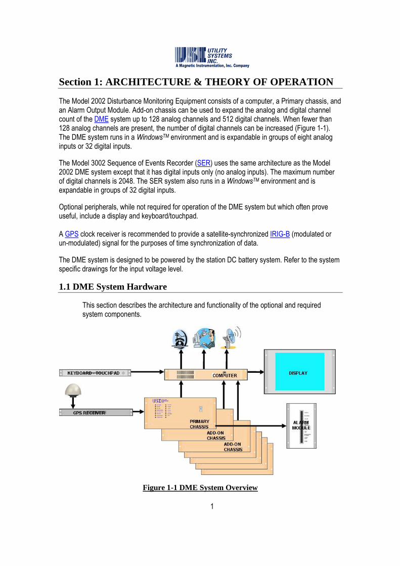
The Model 2002 Disturbance Monitoring Equipment consists of a computer, a Primary chassis, and an Alarm Output Module. Add-on chassis can be used to expand the analog and digital channel count of the DME system up to 128 analog channels and 512 digital channels. When fewer than 128 analog channels are present, the number of digital channels can be increased (Figure 1-1). The DME system runs in a WindowsTM environment and is expandable in groups of eight analog inputs or 32 digital inputs.
The Model 3002 Sequence of Events Recorder (SER) uses the same architecture as the Model 2002 DME system except that it has digital inputs only (no analog inputs). The maximum number of digital channels is 2048. The SER system also runs in a WindowsTM environment and is expandable in groups of 32 digital inputs.
Optional peripherals, while not required for operation of the DME system but which often prove useful, include a display and keyboard/touchpad. A GPS clock receiver is recommended to provide a satellite-synchronized IRIG-B (modulated or un-modulated) signal for the purposes of time synchronization of data.
The DME system is designed to be powered by the station DC battery system. Refer to the system specific drawings for the input voltage level.
1.1 DME System Hardware
This section describes the architecture and functionality of the optional and required system components.
Figure 1-1 DME System Overview

2
1.1.1 GPS Receiver
A GPS receiver is used to provide an IRIG-B time code to the DME system. These devices are available from several manufacturers. Refer to local standards to determine whether a satellite-synchronized time source is required. Refer to the manufacturer’s documentation for distance limitations on the antenna feed line and the receiver output lines.
Figure 1-2 GPS Receiver
1.1.2 Display
A display is used to provide a visual interface to the local DME system user. These devices are available from several manufacturers. This is an optional component for the DME system.
Figure 1-3 Display
1.1.3 Keyboard – Touchpad Drawer
An optional keyboard/touchpad drawer is used to provide input to the DME system from the local user.
3
Figure 1-4 Keyboard – Touchpad
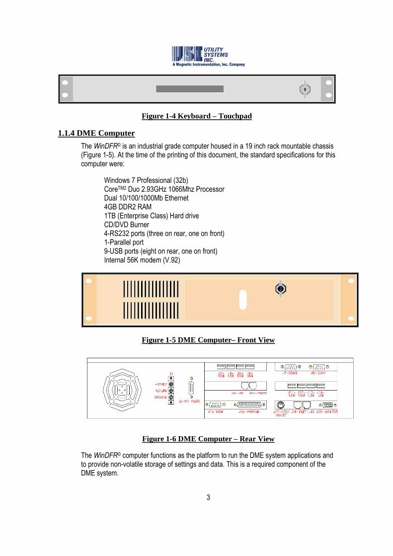
1.1.4 DME Computer
The WinDFR© is an industrial grade computer housed in a 19 inch rack mountable chassis (Figure 1-5). At the time of the printing of this document, the standard specifications for this computer were:
Windows 7 Professional (32b) CoreTM2 Duo 2.93GHz 1066Mhz Processor Dual 10/100/1000Mb Ethernet 4GB DDR2 RAM 1TB (Enterprise Class) Hard drive CD/DVD Burner 4-RS232 ports (three on rear, one on front) 1-Parallel port 9-USB ports (eight on rear, one on front) Internal 56K modem (V.92)
Figure 1-5 DME Computer– Front View
Figure 1-6 DME Computer – Rear View
The WinDFR© computer functions as the platform to run the DME system applications and to provide non-volatile storage of settings and data. This is a required component of the DME system.

4
1.1.5 Primary Chassis
Primary chassis contains the Power Supply module, the I/O board, and the Common board. It also contains analog and digital input circuitry and DSP boards. All chassis contain DSP boards and either analog or digital input circuitry, or both.
The analog circuitry consists of high-voltage and low-voltage boards which condition and digitize the signal inputs. These boards also provide surge protection, input-to-input isolation, and input-to-ground isolation.
The digital circuitry also consists of high-voltage and low-voltage boards which condition and digitize the signal inputs. These boards also provide surge protection, input-to-input isolation, and input-to-ground isolation.
The DSP Board connects to the low-voltage analog and digital boards. The digitized data from the analog and digital inputs is stored in the DSP Board RAM and is processed for trigger conditions. The DSP board monitors signal levels and triggers the record function when a preset level is exceeded. The DSP board also has an embedded USB controller which is used to transfer the data to the DME computer to be stored on the hard drive.
The power supply module of the Primary chassis can be factory configured to accept 250V, 125V, or 48VDC input voltage. A 120VAC input connection is also available. The power supply module provides 3.3V and 5.0V DC outputs to power the DME system, and either 12V or 48V DC output to power the DME computer.
The I/O board is a multifunction board which includes IRIG decoder, system watchdog, alarm output circuitry, and display drivers.
The Common board produces the various DSP timing signals which are provided to the Add-on chassis.
5
Figure 1-7 Primary Chassis
1.1.6 Add-on Chassis
Add-on chassis can contain both analog and digital input circuitry and DSP boards. These chassis usually do not include a Power Supply module, the I/O board, or Common board. However, when the Add-on chassis are not in the same cabinet with the Primary chassis, and in distributed system configurations where the Add-on chassis is more than 100 feet from the primary chassis, these components are included (Section 1.1.7 and Section 1.1.8).
The analog circuitry is exactly the same as included in the Primary chassis consisting of high-voltage and low-voltage boards which condition and digitize the signal inputs and also surge protection, input-to-input isolation, and input-to-ground isolation.
The digital circuitry also consists of high-voltage and low-voltage boards which condition and digitize the signal inputs. These boards also provide surge protection, input-to-input isolation, and input-to-ground isolation.
The DSP Board connects to the low-voltage analog and digital boards. The digitized data from the analog and digital inputs is stored in the DSP Board RAM and is processed for trigger conditions. The DSP board monitors signal levels and triggers the record function when a preset level is exceeded. The DSP board also has an embedded USB controller which is used to transfer the data to the DME computer to be stored on the hard drive.
Figure 1-8 Add-On Chassis
6
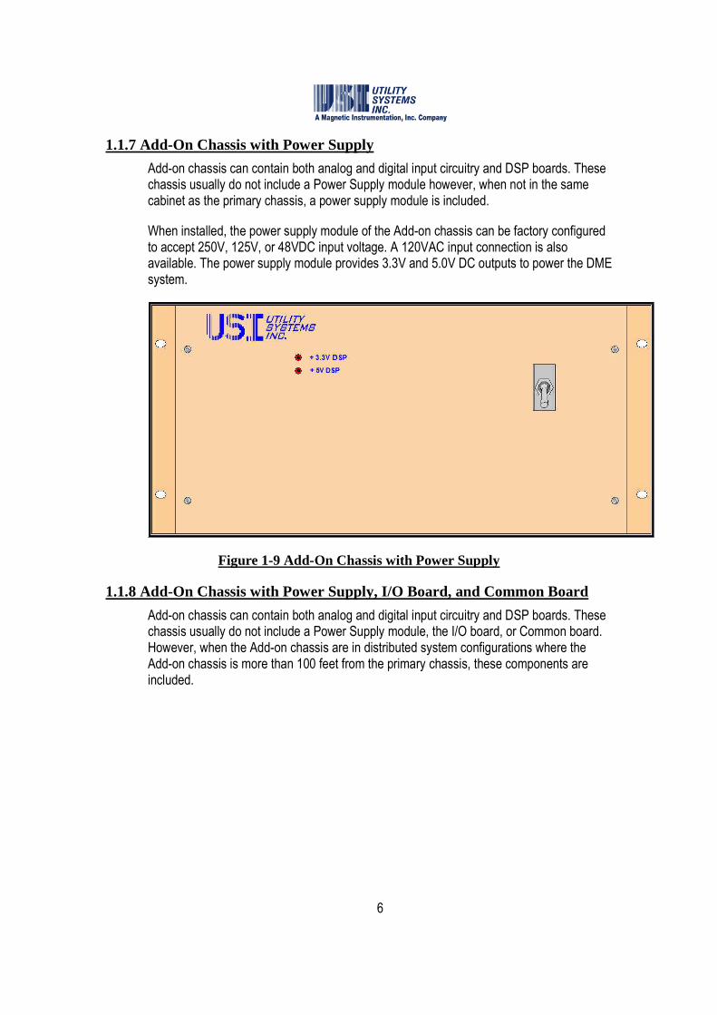
1.1.7 Add-On Chassis with Power Supply
Add-on chassis can contain both analog and digital input circuitry and DSP boards. These chassis usually do not include a Power Supply module however, when not in the same cabinet as the primary chassis, a power supply module is included.
When installed, the power supply module of the Add-on chassis can be factory configured to accept 250V, 125V, or 48VDC input voltage. A 120VAC input connection is also available. The power supply module provides 3.3V and 5.0V DC outputs to power the DME system.
Figure 1-9 Add-On Chassis with Power Supply
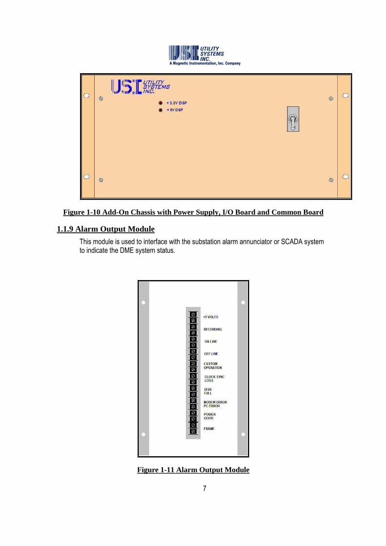
1.1.8 Add-On Chassis with Power Supply, I/O Board, and Common Board
Add-on chassis can contain both analog and digital input circuitry and DSP boards. These chassis usually do not include a Power Supply module, the I/O board, or Common board. However, when the Add-on chassis are in distributed system configurations where the Add-on chassis is more than 100 feet from the primary chassis, these components are included.
7
Figure 1-10 Add-On Chassis with Power Supply, I/O Board and Common Board
1.1.9 Alarm Output Module
This module is used to interface with the substation alarm annunciator or SCADA system to indicate the DME system status.
Figure 1-11 Alarm Output Module

8
1.2 DME System Software
There are a total of three applications that run on the DME system: WinDFR©, USIRemote©, and Scope©.
The WinDFR© program is responsible for functions such as file management, communications to USIMaster©, fault location, auto-call, print, email, etc. and being a local user interface at the DME system. This program must be running for the DME system to be fully functional (see Section 2).
The USIRemote© program is responsible for gathering DFR, SER, Disturbance and Continuous data from the Primary and Add-on chassis and storing it to the local hard drive in the WinDFR© computer. This program must be running for the DME system to be on-line (see Section 3). The Scope© program is used to calibrate the analog inputs, confirm signal wave shapes and input readings, to confirm analog trigger points, and to display digital input status. To run this program, the USIRemote© program must be closed (see Section 4).
9
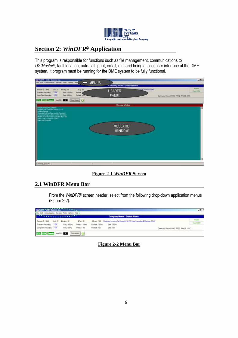
Section 2: WinDFR© Application
This program is responsible for functions such as file management, communications to USIMaster©, fault location, auto-call, print, email, etc. and being a local user interface at the DME system. It program must be running for the DME system to be fully functional.
Figure 2-1 WinDFR Screen
2.1 WinDFR Menu Bar
From the WinDFR© screen header, select from the following drop-down application menus (Figure 2-2).
Figure 2-2 Menu Bar

10
2.1.1 File
The following selections are available on the File menu (Figure 2-3):
Figure 2-3 File Menu
• Printer Setup … Displays the standard Windows™ print setup screen. This window is used to select the USIMaster© default printer.
• Print Message Window This selection sends all the text displayed in the Message Window (Figure 2-1) to the printer selected in the Printer Setup window.
• Print Recent Fault QSum This selection sends the fault summary information of the most recent DME record to the default printer.
• Print Recent Fault QSum + Graph This selection sends the fault summary information and all the waveforms of the most recent DME record to the default printer.
• Exit Closes the WinDFR© application window.
Caution: The WinDFR© application must be running to be fully operational. Exiting WinDFR© will inhibit file management, communication, printing, etc.
2.1.2 Edit
The following selections are available on the Edit menu (Figure 2-4):

11
Figure 2-4 Edit Menu
• WinDFR© Configuration This selection displays the WinDFR© System Configuration window. This window is used to configure the WinDFR© application. Choose one of three separate screens: General, File Paths/Time Zone, or Continuous Recording. For complete details on WinDFR© Configuration, see Section 2.3.
• Calibration Record The Calibration Record is a setup file which contains the DME system parameters for the analog and digital input channels as well as the analog trigger channels. For complete details on the Calibration Record menu, see Section 2.4.
o Edit Cal. Record: This selection displays the Edit Calibration Record window. This window is used to view and modify Analog, Digital, and Trigger channel assignments. For complete details on editing the Calibration Record.
o Backup Cal. Record: This selection is used to create a backup copy of the Calibration Record.
� To Remote Setup Path This selection creates a copy of the calibration record within the Cal. Rec. Path as configured in WinDFR© configuration. The backup file is named RXXXXCal.bak where XXXX is the Remote ID number assigned to the selected DME system.
� Choose Backup Path This selection creates a copy of the Calibration Record within the path selected in the Browse for Folder window. The backup file is named RXXXXCal.bak where XXXX is the Remote ID number assigned to the selected DME system.
o Restore Cal. Record: This selection is used to restore a backup copy of the Calibration Record.

12
� From Remote Setup Path This selection restores the backup copy of the Calibration Record from the Cal. Rec. Path as configured in WinDFR© configuration. The backup file will be renamed from RXXXCal.bak to RXXXX.cal and will overwrite the Calibration Record currently in use.
� From Specified Path This selection restores the backup copy of the calibration record from the path selected in the Browse for Folder window. The backup file will be renamed from RXXXCal.bak to RXXXX.cal and will overwrite the Calibration Record currently in use.
o Print Cal. Record: Choose to Preview or Print all the parameters of the Analog, Trigger, and Digital channels stored in the Calibration Record.
• Line Group Record The Line Group Record is a setup file used to group analog channels related to a specific transmission line or generator output (e.g., Va, Vb, Vc, Ia, Ib, Ic, In). Line Group files are used by the DME system to perform automatic distance-to-fault calculations and by the USIMaster© to perform manual distance-to-fault calculations and Graphic Signal Processing Data analysis. For complete details on the Line Group menu, see Section 2.5.
o Edit Line Group Record: This selection displays the Edit Line-Group Record window allowing the user to add, delete, or edit Line Group parameters. For complete details on editing the Line Group Record.
o Print Line Group Record: This selection is used to Preview or Print all the parameters of the Line Group Record to the default printer.
2.1.3 Communication
The following selections are available on the Communication menu (Figure 2-5) of the WinDFR© header screen:

13
Figure 2-5 Communication Menu
• Show Comm. Screen This selection displays the Communication Status window. This window shows what the modem or network connection does when it is active. It also shows the transfer progress of files being uploaded to or downloaded from the DME system (Figure 2-6).
Figure 2-6 Communication Status Window
����Note: The messages displayed in this window are automatically logged in an ASCII
formatted file named CommTrace.wri. This file is located in the working directory of the WinDFR© application. Additionally, a right-click in the Communication Status window displays a pop-up menu with the choices: Undo, Cut, Copy, Paste, Delete and Select All. These selections are used to copy the contents manually to a file for trouble-shooting.
����Note: The mouse symbol � is used in this document to denote that a mouse-right-click
is required to view the tagged object.
• Modem – Choose Modem This selection displays the Choose Modem window (Figure 2-7). This window displays the list of modems installed on the DME system computer. Select a
modem and click the OK button to choose a modem.

14
Figure 2-7 Choose Modem
• Modem – Configure Modem Changes to the default modem configuration are rarely needed but can be made when necessary. For example, configuration changes may be necessary during an attempt to connect to the USIMaster© via modem. Select Configure Modem (Figure 2-8) to display preferences and to make changes to the default configuration.
Figure 2-8 Configure Modem
• Direct COM Direct COM method of communication is used when USIMaster© is connected to the DME system via an RS-232 serial bus. This connection may also be made via a null modem serial cable directly to a COM port on the DME system computer. This connection may also be made using a third-party device which creates a virtual serial connection over Ethernet.

15
Select Direct COM from the Communication menu to display the following sub-menu choices.
o Choose COM: This selection displays the Choose COM window. This window lists the physical COM ports available on the DME system computer. Select from this list the COM port to be used to connect to the DME system (Figure 2-9).
Figure 2-9 Choose COM Port
o If a virtual COM port is being used, select the Additional Comm Port check-box to display the Choose serial port # form and manually enter the virtual COM port number. COM9 is the highest port number that may
be entered. Click Use or Discard to add or remove
virtual COM ports. Click OK to save the selection (Figure 2-10).
Figure 2-10 Choose Virtual COM Port
o Baud Rate: This drop-down list is used to set the communication rate for the Direct

16
COM connection (Figure 2-5). The baud rate setting for WinDFR© must match the baud rate setting for USIMaster©. The factory default setting is 115,200.
• Set Network Port # … This selection displays the Set New Network Port#: window (Figure 2-11). This window is used to enter a new Network Port number if the 1024 port is blocked on your network. The port number setting in WinDFR© must match the port number setting in USIMaster©. The default port number is set to 1024.
Figure 2-11 Set Network Port Number
• Call Master This selection establishes a communication connection from the DME system to USIMaster©. Once connected, USIMaster© will follow the auto-call configuration settings and then disconnect.
• Hang Up This selection terminates any communication connection with USIMaster©.
2.1.4 Services
The following selections are available on the Services menu (Figure 2-12) of the WinDFR© header screen:
Figure 2-12 Services Menu
17
• Test Run This selection sends a command to the DME system to manually initiate a DFR and DDR Record.
����Note: In the USIMaster© application a letter Y displays in the Test column of the Quick
Summary and History Data screens to indicate when the fault was a Test Run.
• Trace File Trace files are log files containing internal operations, computer memory levels, and error messages of the DME system applications and are useful for troubleshooting. Applications which record trace files on the DME system are WinDFR© and USIRemote©. These files are ASCII formatted and are displayed using Microsoft WordPad. Trace files are limited to 500kB in size. When a trace files reaches 500kB it is renamed changing the file extension to a sequential number (e.g. Trace01.001, Trace01.002, etc). These backup trace files may be downloaded using the USIMaster© application. The WinDFR© and Remote trace files are located in the Setup folder as configured in the WinDFR© Configuration (Section 2.3). They are and named TraceXX.wri for USIRemote© and WTraceXX.wri for WinDFR©; where XX is the remote ID number.
o Show Remote Trace File: This selection displays the Trace File for the USIRemote© application.
o Show WinDFR© Trace File: This selection displays the Trace File for the WinDFR© application.
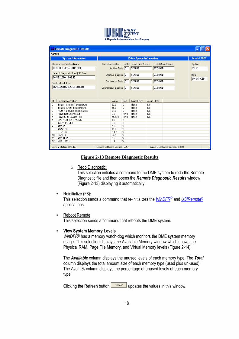
• Remote Diagnostic A Remote diagnostic file is automatically updated at five minute intervals. This file contains crucial system status information such as System Online/Offline status, clock synchronization and system time, disk drive free space, USIRemote© and WinDFR© application version numbers, and internal computer power supply voltages, temperatures, and cooling fan speeds.
o Show Result: This selection opens the Remote Diagnostic Results window (Figure 2-13) and displays the contents of the Remote Diagnostic file.
18
Figure 2-13 Remote Diagnostic Results
o Redo Diagnostic: This selection initiates a command to the DME system to redo the Remote Diagnostic file and then opens the Remote Diagnostic Results window (Figure 2-13) displaying it automatically.
• Reinitialize (F8): This selection sends a command that re-initializes the WinDFR© and USIRemote© applications.
• Reboot Remote: This selection sends a command that reboots the DME system.
• View System Memory Levels WinDFR© has a memory watch-dog which monitors the DME system memory usage. This selection displays the Available Memory window which shows the Physical RAM, Page File Memory, and Virtual Memory levels (Figure 2-14). The Available column displays the unused levels of each memory type. The Total column displays the total amount size of each memory type (used plus un-used). The Avail. % column displays the percentage of unused levels of each memory type.
Clicking the Refresh button updates the values in this window.

19
Figure 2-14 Available Memory
• Show All Ser Abnormal Or Stopped Channels This selection sends a command to the DME system to scan each of the digital event inputs and displays a summary of all inputs which are in the abnormal state or have been stopped by the Run/Stop setting in the Calibration Record (Figure 2-15).
Figure 2-15 SER Abnormal or Stopped Channels
The Date-Time column displays the timestamp when the digital input became abnormal in each row. The Event column displays channel number for the digital input in each row. The Now column displays the state of the contact being monitored by the digital input in each row; O (open) or C (closed). The Normal column displays the condition of the digital input in each row; N (normal) or A (abnormal).

20
The Sync column displays the condition of the GPS time synchronization at the time this event changed to the abnormal state. The Description column displays the descriptor for the abnormal digital input as it was entered in the Calibration Record.
• Administrator Administrator is a level of password protection that prevents setting changes from being made by unauthorized users. This feature prevents changes in WinDFR© Configuration, Calibration Record, and Line Group Record. When Administrator is selected, the system prompts the user to enter the Administrator password. If the password is entered correctly: a check-mark displays beside this menu item; the administrator access icon color changes from red to green; and administrator level privileges are granted. If Administrator is not checked, users will be prompted to enter the administrator password when a Save button is selected. Non-administrator users can open setup files and view them but can not save them without the Administrator password.
• Change Administrator Password This selection displays the Change Administrator Password window (Figure 2-16). This window allows Administrator users to set or modify an Administrator password. Knowledge of the present administrator password is required to change the password.
Figure 2-16 Change Administrator Password
2.1.5 Tools
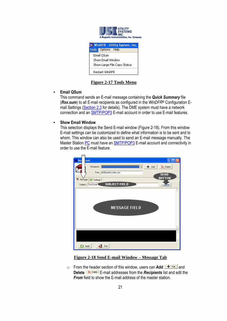
The following selections are available on the Tools menu (Figure 2-17) of the WinDFR© header screen (Figure 2-2):
21
Figure 2-17 Tools Menu
• Email QSum This command sends an E-mail message containing the Quick Summary file (Rxx.sum) to all E-mail recipients as configured in the WinDFR© Configuration E-mail Settings (Section 2.3 for details). The DME system must have a network connection and an SMTP/POP3 E-mail account in order to use E-mail features.
• Show Email Window This selection displays the Send E-mail window (Figure 2-18). From this window E-mail settings can be customized to define what information is to be sent and to whom. This window can also be used to send an E-mail message manually. The Master Station PC must have an SMTP/POP3 E-mail account and connectivity in order to use the E-mail feature.
Figure 2-18 Send E-mail Window – Message Tab
o From the header section of this window, users can Add and
Delete E-mail addresses from the Recipients list and edit the From field to show the E-mail address of the master station.
22
o The Message screen tab is an E-mail editor screen used to send an E-mail message manually to the E-mail addresses on the Recipients list. When the Recipients list, Subject field, and Message field have been completed, send the message by clicking the Send button.
� Subject field: When manually preparing an E-mail, enter a message subject in this field.
����Note: The subject field of E-mail messages sent automatically by WinDFR© is populated
with the unique Remote ID number and Station Name of the recorder about which the message pertains.
� Message field: When manually preparing an E-mail, enter the body of the message in this field.
����Note: When automatic E-mail messages are sent by WinDFR© this field is populated
with Quick Summary and Distance-to-Fault information for the DME record which initiated the E-mail message.
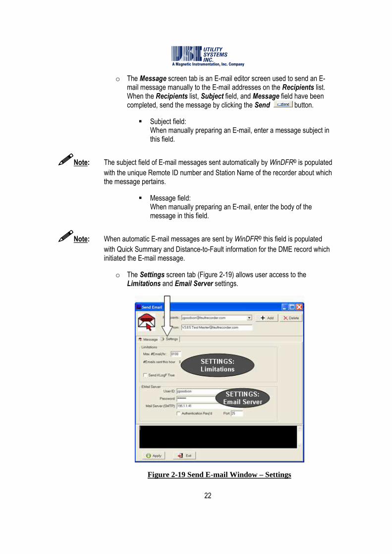
o The Settings screen tab (Figure 2-19) allows user access to the Limitations and Email Server settings.
Figure 2-19 Send E-mail Window – Settings

23
� Limitations Max. #Email/hr: This setting limits the number of messages sent automatically by the DME system in a single 60 minute period.
#Emails sent this hour This file displays the total number of E-mail messages which were sent within the current hour.
�Send if LogF True This check box enables the use of the Boolean Auto Call, Auto E-mail, and Auto Print decision logic to be applied to E-mail messages sent automatically by the DME system application (see Section 2.3.1). When this box is checked, automatic E-mails are filtered by the Boolean decision logic, as entered in the WinDFR© configuration, and sent only if the logic is true.
� E-mail Server User ID: This field is used to enter the User ID for the E-mail account assigned to the DME system.
Password: This field displays allowing users to enter a User Password for the E-mail account assigned to the master station. If no password is required by your mail server, this field may be left blank. Mail Server (SMTP): This field is used to enter the IP address of the SMTP Mail Server. �Authentication Req’d: This check box displays allowing users to enable authentication, if required by your mail server. Port: This field allows users to enter the port number of the IP address being used for E-mail message transport.
����Note: The Outgoing Mail (SMTP), Port #, and User ID fields must be entered. Contact
your network administrator for this information.
o The Apply button is used to save Settings entered within the Send E-mail window.
o The Exit button is used to close the Send E-mail window.

24
• Show Large File Copy Status This selection displays the Large File Copying window (Figure 2-20). This window displays the status of continuous recording data which is being backed up. Continuous data can be scheduled to be backed up by using the Continuous Data Control Panel from the Cont-Rec menu in USIMaster©.
Figure 2-20 Large File Copying Window
• Restart WinDFR© This selection closes the WinDFR© application, displays the Delay Run window (Figure 2-21), and after a 30 second delay restarts WinDFR©.
Figure 2-21 Delay Run Window
2.1.6 Options
The following selections are available on the Options menu (Figure 2-22) of the WinDFR© header screen:

25
Figure 2-22 Options Menu
• Continuous Recording The following selections are available from this menu:
o Show Status Screen: This selection displays the Continuous Recording Status window (Figure 2-23). This window shows status information as continuous values are being calculated.
Figure 2-23 Continuous Recording Status Screen
A right-click in the Communication Status message window displays a pop-up menu with the choices: Undo, Cut, Copy, Paste, Delete, Select All, Right to left Reading order, Show Unicode control characters, and Insert Unicode control character. These can be used to copy the contents to a file manually for communications trouble-shooting.

26
The Keep this information in a file checkbox can be used to save the information displayed in the window to a file named ToValTrace.wri located at the Remote Setup path (e.g. D:\Setup).
o Frequency: The following selections are available on the Frequency menu:
� Display Channel Freq … This selection displays the Channel Frequency window. This window is used to select the analog input channel for which frequency is displayed in the WinDFR© status bar (Figure 2-24).
� Reset Freq This selection clears the data used to calculate the frequency value.
o RMS: The following selections are available on the RMS menu:
� Display Channel RMS … This selection displays the Channel RMS window. This window is used to select the analog input channel for which RMS is displayed in the WinDFR© status bar (Figure 2-24).
� Reset RMS This selection clears the data used to calculate the RMS value.
o Phase: The following selections are available on the Phase menu:
� Display Channel Phase … This selection displays the Channel Phase window. This window is used to select the analog input channel for which phase is displayed in the WinDFR© status bar (Figure 2-24).
� Change Reference Channel … This selection displays the Channel Phase Reference window. This window is used to select the analog input channel to be reference for which phase is calculated and displayed in the WinDFR© status bar (see Section 2.2.2).
� Reset Phase This selection clears the data used to calculate the phase value.
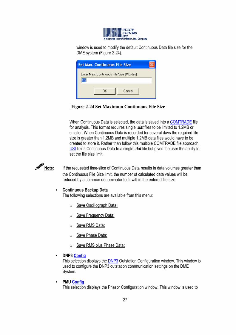
o Set Max Continuous File Size: This selection displays the Set Max. Continuous File Size window. This
27
window is used to modify the default Continuous Data file size for the DME system (Figure 2-24).
Figure 2-24 Set Maximum Continuous File Size
When Continuous Data is selected, the data is saved into a COMTRADE file for analysis. This format requires single .dat files to be limited to 1.2MB or smaller. When Continuous Data is recorded for several days the required file size is greater than 1.2MB and multiple 1.2MB data files would have to be created to store it. Rather than follow this multiple COMTRADE file approach, USI limits Continuous Data to a single .dat file but gives the user the ability to set the file size limit.
����Note: If the requested time-slice of Continuous Data results in data volumes greater than
the Continuous File Size limit, the number of calculated data values will be reduced by a common denominator to fit within the entered file size.
• Continuous Backup Data The following selections are available from this menu:
o Save Oscillograph Data:
o Save Frequency Data:
o Save RMS Data:
o Save Phase Data:
o Save RMS plus Phase Data:
• DNP3 Config This selection displays the DNP3 Outstation Configuration window. This window is used to configure the DNP3 outstation communication settings on the DME System.
• PMU Config This selection displays the Phasor Configuration window. This window is used to
28
configure the PMU communication and Synchrophasor settings on the DME System.
����Note: PMU/Synchrophasor is an add-on software feature provided at additional charge.
For information and pricing to enable this feature, contact Utility Systems, Inc.
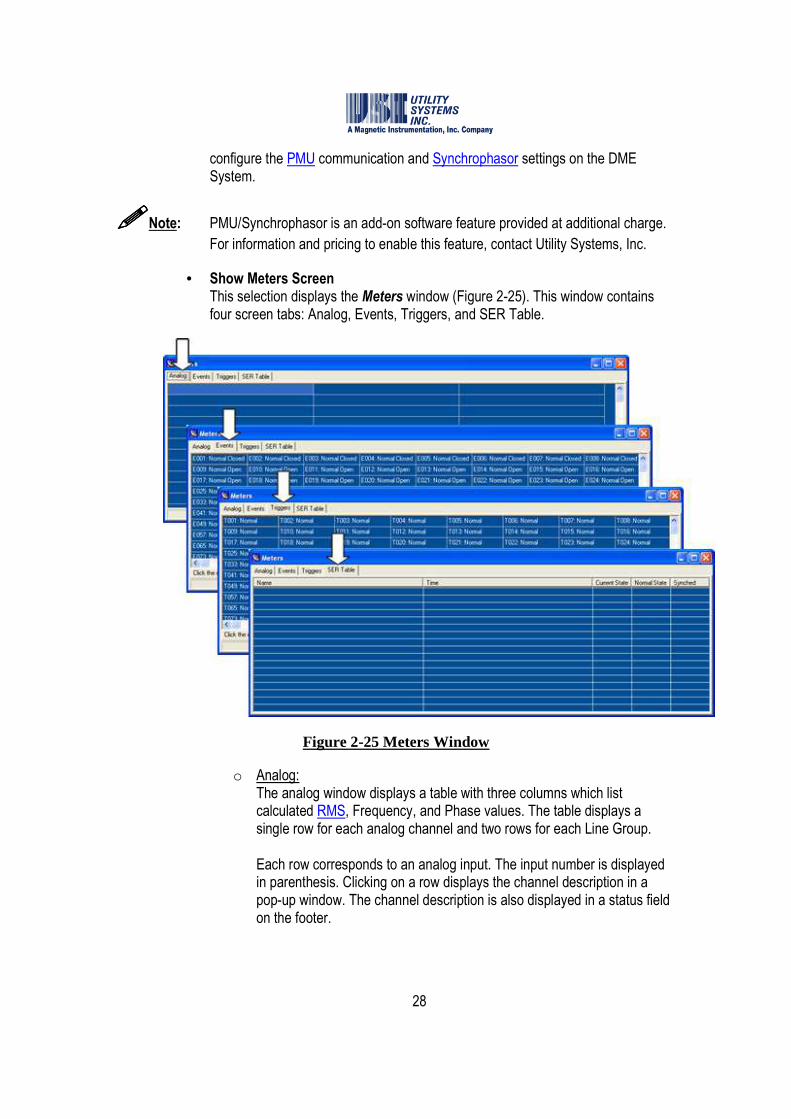
• Show Meters Screen This selection displays the Meters window (Figure 2-25). This window contains four screen tabs: Analog, Events, Triggers, and SER Table.
Figure 2-25 Meters Window
o Analog: The analog window displays a table with three columns which list calculated RMS, Frequency, and Phase values. The table displays a single row for each analog channel and two rows for each Line Group. Each row corresponds to an analog input. The input number is displayed in parenthesis. Clicking on a row displays the channel description in a pop-up window. The channel description is also displayed in a status field on the footer.
29
All values are updated every ten seconds. The timestamp for these values is displayed in a status field on the footer.
o Events: The events window displays a table with a row and eight columns for each multiple of eight event channel inputs. Each cell in this table displays the status for the indicated event input number. The status indications are Normal or Alarm and Open or Closed. The description for each channel is displayed in a pop-up window by clicking on the cell. The selected channel description is also displayed in a status field on the footer. All values are updated every ten seconds. The timestamp for these values is displayed in a status field on the footer.
o Triggers: The triggers window displays a table with a row and eight columns for each multiple of eight analog triggers. Each cell in this table displays the status for the indicated trigger number. The status indication is Normal or Alarm. The description for each analog trigger is displayed in a pop-up window by clicking on the cell. The selected analog trigger description is also displayed in a status field on the footer. All values are updated every ten seconds. The timestamp for these values is displayed in a status field on the footer.
o SER Table: The SER Table window displays five columns titled Name, Time, Current State, Normal State, and Synched. This table is updated dynamically and displays the state change of any event input which is configured as an SER in the Calibration Record.
� Name This column displays the event input number and description.
� Time This column displays the date and time that the state change occurred.
� Current State This column displays Open or Closed as the condition of the event contact.

30
� Normal State This column displays Normal or Alarm based on the Normal State setting in the Calibration Record.
� Synched This column displays Synched or UnSynched based on the synchronization status of the IRIG-B signal.
2.1.7 Help
The following selections are available on the Help menu (Figure 2-26) of the WinDFR© application:
Figure 2-26 Help Menu
• WinDFR© Help
o Contents: Displays the contents of the WinDFR© Help file.

31
o Index: Displays the index to the WinDFR © Help file.
o Find: Displays the screen used to search WinDFR © Help topics for a specific word.
• About This selection displays the WinDFR© release version and copyright information, address, telephone numbers, and web addresses of Utility Systems, Inc.
2.2 WinDFR© Screens
The WinDFR© has three main screens: Header screen, Footer screen and Message Window screen.
2.2.1 Header Screen
The WinDFR© screen header displays general information about the DME system (Figure 2-27). The information displayed is extracted from the WinDFR© configuration (Section 2.3) and the Calibration Record (Section 2.4).
Figure 2-27 WinDFR© Header Screen
• Company Name The header title bar displays the company name as entered in the company name field of the WinDFR© configuration.
• Station Name The header title bar displays the station name as entered in the Station field of the Calibration Record.
• Remote ID This field displays the unique remote identification number assigned to the DME system in the Remote DFR ID field of the WinDFR© configuration.
• Unit This field displays the number of computers running USIRemote© within the DME system.

32
• #Analog This field displays the total number of analog input channels available for the DME system.
• #Trig This field displays the total number of analog triggers available for the DME system.
• #Event This field displays the total number of event input channels available for the DME system.
• Monitoring Incoming Call through This field displays the medium being monitored by WinDFR© for incoming communication connections. The possible media are modem, Network, and COM port. If modem is being monitored, the modem name displayed is extracted from the WindowsTM device manager. If an RS-232 port is being monitored, the port number is displayed.
• Modem This displays in green letters if WinDFR© is able to communicate with the selected modem. This indicator displays in red letters if WinDFR© cannot communicate with the selected modem. This indicator displays in grey letters if no modem is selected.
• Direct COM This displays in green letters if WinDFR© is able to communicate with the selected serial port. This indicator displays in red letters if WinDFR© cannot communicate with the selected serial port. This indicator displays in grey letters if no serial port is selected.
• Transient Recording This row displays transient data recording status and settings. When Transient Recording is enabled, the status word ON is displayed.
o Freq: This field displays the sample frequency of the Transient Recording as selected in the Transient Frequency drop-down list of the Calibration Record.
o Prefault: This field displays the Transient Prefault setting as entered in the Calibration Record.
o Postfault: This field displays the Transient Postfault setting as entered in the Calibration Record.

33
o Limit: This field displays the Transient Fault Limit setting as entered in the Calibration Record.
• Long Term Recording This row displays transient data recording status and settings. When Long Term Recording is enabled, the status word ON is displayed. When Long Term Recording is disabled, the status word OFF is displayed. Long Term Recording is disabled by selecting 0Hz in the LONGTERM Frequency drop-down list.
o Freq: This field displays the sample frequency of the Long Term Recording as selected in the Long Term Frequency drop-down list of the Calibration Record.
o Prefault: This field displays the Long Term Prefault setting as entered in the Calibration Record.
o Postfault: This field displays the Long Term Postfault setting as entered in the Calibration Record.
o Limit: This field displays the sum of the Long Term Prefault and Postfault settings.
• Continuous Recording This row displays the continuous recording functions that are enabled. Continuous recording functions are enabled in WinDFR© configuration (see Section 2.3.3). The continuous recording functions displayed here are: RMS, FREQ, PHASE, and OSC.
• Status Indicators This row displays status of the following:
o DISK: This indicator displays green if the available disk free space is greater than the Disk Alarm On if Below limit in the WinDFR© configuration. This indicator displays red if the free space is less than the limit.
o COM: This indicator displays green if WinDFR© is able to access all devices used for monitoring incoming communication connections. This indicator displays red if any device is inaccessible.

34
o Remote: This indicator displays green if WinDFR© detects that the USIRemote© application is running. This indicator displays red when the USIRemote© application is closed.
Warning: If the Remote indicator is red , the DME system is off-line and is not recording data.
o Next FID: This displays a fault counter indicating the identification number for the next record received.
o Show Meters: This button displays the Meters window (Figure 2-25).
o Administrator Off/On: Certain functions can be performed only by an operator who has Administrator credentials. This button is green and these functions are enabled only after these credentials have been established. If the operator has not established Administrator credentials the button remains red and the functions remain locked. See Section 2.1.4 – Administrator/Change Administrator Password for setup details.
2.2.2 Footer Screen
The WinDFR© screen footer (Figure 2-28) displays calculated values of frequency, RMS, and phase for the channels selected in the Continuous Recording setup of the Options menu (see Section 2.1.6).
Figure 2-28 WinDFR© Footer – Continuous Status Bar
2.2.3 Message Window Screen
The WinDFR© Message Window (Figure 2-29) displays information regarding the operations of the application. There is a right-click menu which allows this information to be moved to the clip-board or deleted.

35
Figure 2-29 WinDFR© Message Window
2.3 WinDFR© Configuration
Open the WinDFR© Configuration window by selecting it on the Edit menu. The WinDFR© Configuration window contains four different screens which can be accessed by clicking on the appropriate tab (Figure 2-30). These tabs are labeled General, File Paths/Time Zone, Continuous Recording, and Memory Options.
2.3.1 WinDFR© Configuration Screen – General
The contents of the WinDFR© Configuration – General Tab screen are outlined below:
36
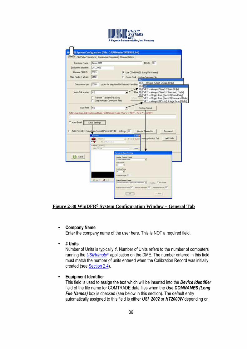
Figure 2-30 WinDFR© System Configuration Window – General Tab
• Company Name Enter the company name of the user here. This is NOT a required field.
• # Units Number of Units is typically 1. Number of Units refers to the number of computers running the USIRemote© application on the DME. The number entered in this field must match the number of units entered when the Calibration Record was initially created (see Section 2.4).
• Equipment Identifier This field is used to assign the text which will be inserted into the Device Identifier field of the file name for COMTRADE data files when the Use COMNAMES (Long File Names) box is checked (see below in this section). The default entry automatically assigned to this field is either USI_2002 or HT2000W depending on

37
the model of the system. This is a variable length field containing alpha-numeric characters and some punctuation marks. Characters disallowed are: comma, question mark, quotation mark, forward slash, backward slash, less than, greater than, asterisk, pipe, and colon.
• Remote DFR ID This field contains the unique Remote ID number assigned to the selected DME system. This entry is restricted to be a number from one to four digits in length.
• ����Use COMNAMES (Long File Names) This checkbox enables the COMNAMES feature. When this box is selected, the WinDFR© program will automatically name the data files in accordance with the IEEE C37.232 standard.
• Max # Faults in Qsum This field contains the maximum number of fault summary lines that can be inserted into the Quick Summary file. The default number is 50; the maximum number is 9999.
• ����Create Fault Location Summary File This checkbox enables the creation of an information file in the working directory of the WinDFR© application. This file contains summary information about the DME records which contain a successful fault location calculation.
• One sample per xxxxx cycles for long term RMS record if enabled Long Term RMS is a separate data file derived from the Long Term Oscillography data file. This data file is automatically created by the DME system and contains calculated RMS values. These RMS values are calculated using a window of Long Term Oscillography data. This setting defines window size for the data used in the calculation. The window slide increment is equal to the window size; therefore, there is no overlapped or skipped data between successive calculations. Example: On a 60 Hz power system, a setting of One sample per 0001 cycles results in 60 calculations per second, One sample per 0002 cycles results in 30 calculations per second, etc.
• Auto Call Master This drop-down menu is used to enable the Auto-Call feature and to determine what data is to be downloaded to USIMaster© during an Auto-Call session (Figure 2-31).
38
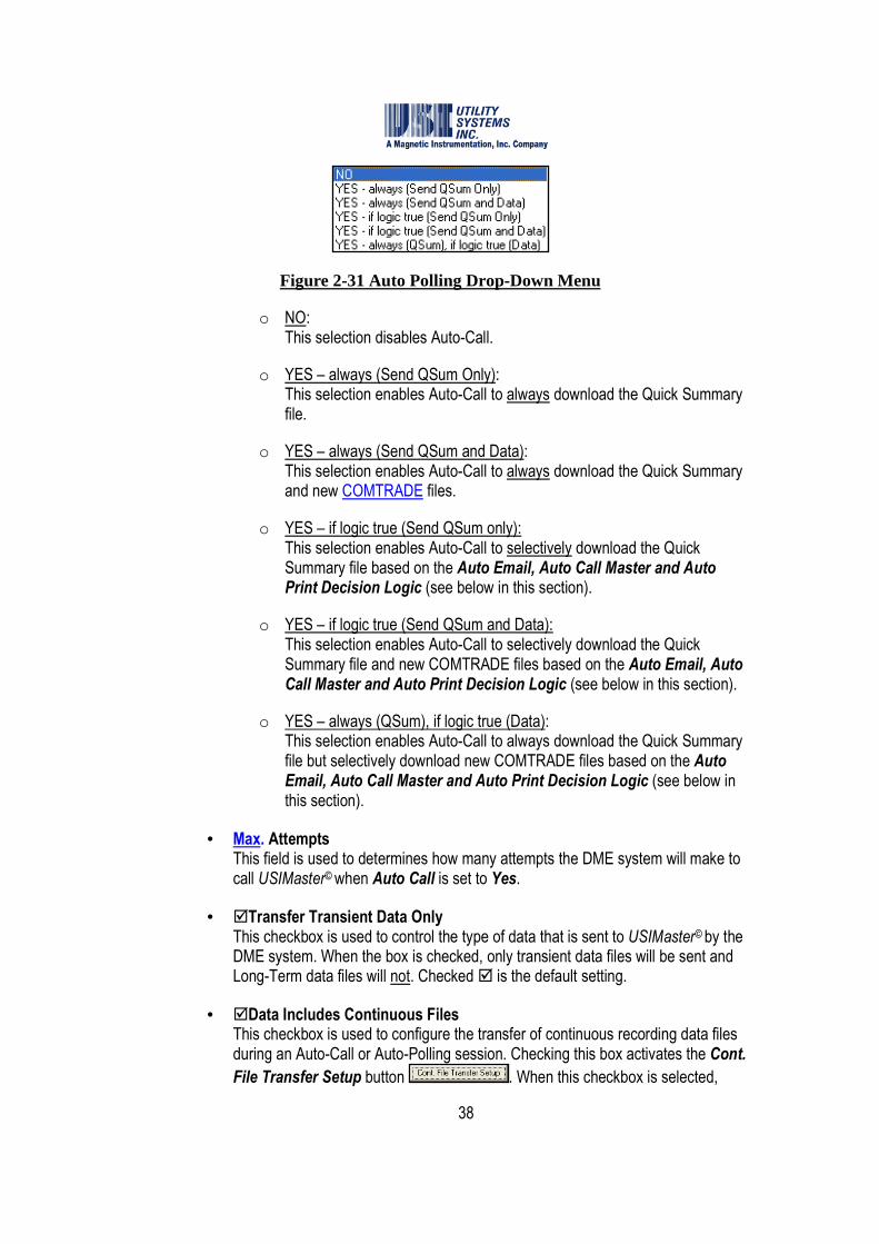
Figure 2-31 Auto Polling Drop-Down Menu
o NO: This selection disables Auto-Call.
o YES – always (Send QSum Only): This selection enables Auto-Call to always download the Quick Summary file.
o YES – always (Send QSum and Data): This selection enables Auto-Call to always download the Quick Summary and new COMTRADE files.
o YES – if logic true (Send QSum only): This selection enables Auto-Call to selectively download the Quick Summary file based on the Auto Email, Auto Call Master and Auto Print Decision Logic (see below in this section).
o YES – if logic true (Send QSum and Data): This selection enables Auto-Call to selectively download the Quick Summary file and new COMTRADE files based on the Auto Email, Auto Call Master and Auto Print Decision Logic (see below in this section).
o YES – always (QSum), if logic true (Data): This selection enables Auto-Call to always download the Quick Summary file but selectively download new COMTRADE files based on the Auto Email, Auto Call Master and Auto Print Decision Logic (see below in this section).
• Max. Attempts This field is used to determines how many attempts the DME system will make to call USIMaster© when Auto Call is set to Yes.
• �Transfer Transient Data Only This checkbox is used to control the type of data that is sent to USIMaster© by the DME system. When the box is checked, only transient data files will be sent and Long-Term data files will not. Checked � is the default setting.
• �Data Includes Continuous Files This checkbox is used to configure the transfer of continuous recording data files during an Auto-Call or Auto-Polling session. Checking this box activates the Cont.
File Transfer Setup button . When this checkbox is selected,
39
continuous recording data will be transferred to USIMaster© during a DME system Auto-Call session as configured in the Cont. File Transfer Setup. If continuous recording data is to be transferred to USIMaster© only during an Auto-Polling session, un-check this box after selecting the continuous data types and the analog channels from which data is to be transferred.
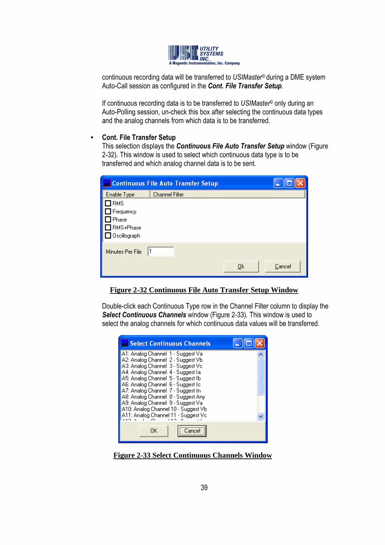
• Cont. File Transfer Setup This selection displays the Continuous File Auto Transfer Setup window (Figure 2-32). This window is used to select which continuous data type is to be transferred and which analog channel data is to be sent.
Figure 2-32 Continuous File Auto Transfer Setup Window
Double-click each Continuous Type row in the Channel Filter column to display the Select Continuous Channels window (Figure 2-33). This window is used to select the analog channels for which continuous data values will be transferred.
Figure 2-33 Select Continuous Channels Window

40
• Auto Print This drop-down list (Figure 2-34) is used to enable WinDFR© to print and control what is to be printed when a new DME record is created. This drop-down list is also used to control what is to be printed by WinDFR© when a new DME record is received. This printout is sent to the default printer.
Figure 2-34 Auto Print Drop Down List
o NO: This selection disables Auto-Print.
o YES – always (Print QSum Only): This selection instructs Auto-Print to always print the Quick Summary file.
o YES – always (Print QSum and Data): This selection instructs Auto-Print to always print the Quick Summary and new COMTRADE files.
o YES – if logic true (Print QSum only): This selection enables Auto-Print to print the Quick Summary file selectively based on the Auto Email, Auto Call Master and Auto Print Decision Logic in the WinDFR© configuration (see below in this section).
o YES – if logic true (Print QSum and Data): This selection instructs Auto-Print to print the Quick Summary file and new COMTRADE files selectively based on the Auto Email, Auto Call Master and Auto Print Decision Logic Boolean equation in the WinDFR©
configuration (see below in this section).
o YES – always (QSum), if logic true (Data): This selection instructs Auto-Print to always print the Quick Summary file but selectively print new COMTRADE files based on the Auto Email, Auto Call Master and Auto Print Decision Logic Boolean equation in the WinDFR© configuration (see below in this section).
41
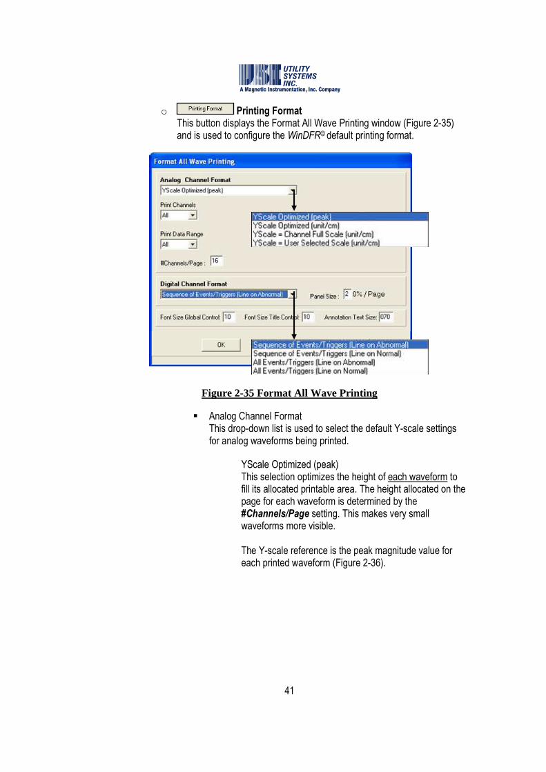
o Printing Format This button displays the Format All Wave Printing window (Figure 2-35) and is used to configure the WinDFR© default printing format.
Figure 2-35 Format All Wave Printing
� Analog Channel Format This drop-down list is used to select the default Y-scale settings for analog waveforms being printed.
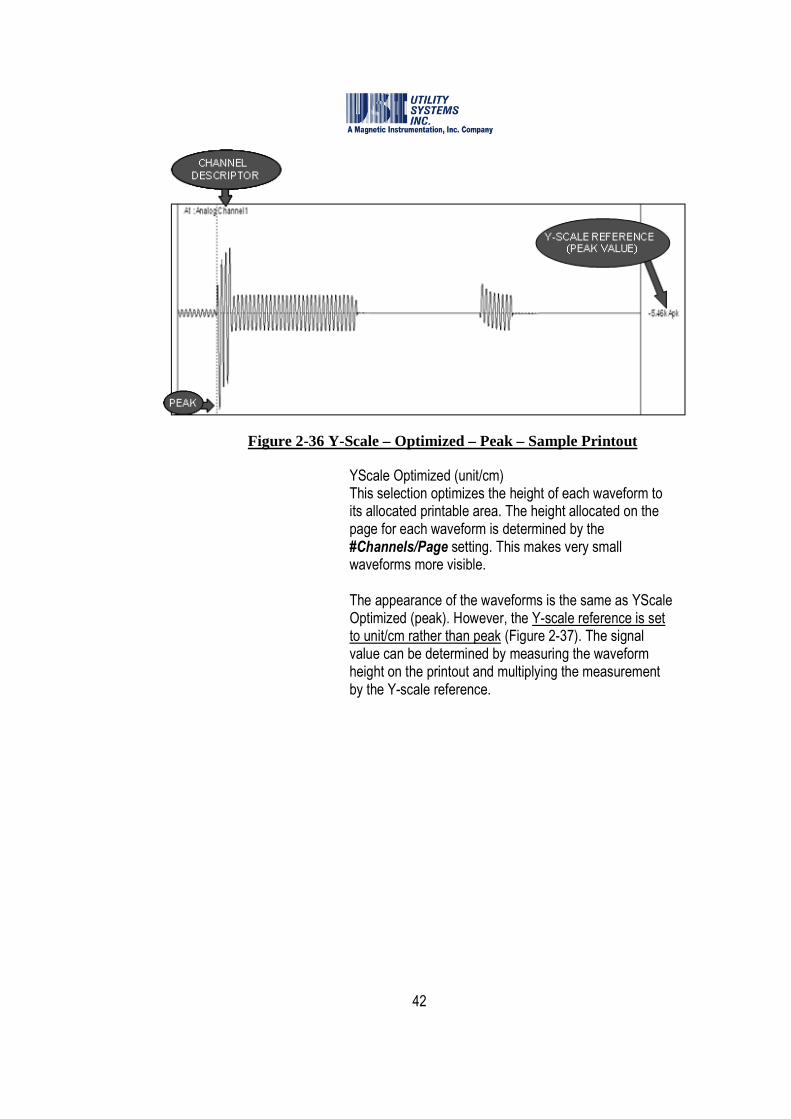
� YScale Optimized (peak) This selection optimizes the height of each waveform to fill its allocated printable area. The height allocated on the page for each waveform is determined by the #Channels/Page setting. This makes very small waveforms more visible. The Y-scale reference is the peak magnitude value for each printed waveform (Figure 2-36).
42
Figure 2-36 Y-Scale – Optimized – Peak – Sample Printout
� YScale Optimized (unit/cm) This selection optimizes the height of each waveform to its allocated printable area. The height allocated on the page for each waveform is determined by the #Channels/Page setting. This makes very small waveforms more visible. The appearance of the waveforms is the same as YScale Optimized (peak). However, the Y-scale reference is set to unit/cm rather than peak (Figure 2-37). The signal value can be determined by measuring the waveform height on the printout and multiplying the measurement by the Y-scale reference.

43
Figure 2-37 Y-Scale – Optimized – Unit/Centimeter – Sample Printout
� YScale = Channel Full Scale (unit/cm) This selection sets the Y-scale to the Analog Channel Full Scale value entered in the Calibration Record (Section 2.4). The Y-scale reference is set to unit/cm. The signal value can be determined by measuring the waveform height on the printout and multiplying the measurement by the Y-scale reference (Figure 2-38).
Figure 2-38 Y-Scale – Channel Full-Scale – Unit/Centimeter – Sample Printout

44
� YScale = User Selected Scale (unit/cm) This selection sets the Y-scale height for each waveform to the value entered in the YScale V or A field (Figure 2-39).
Figure 2-39 User Selected Y-Scale
The Y-scale reference is set to unit/cm. The signal value can be determined by measuring the waveform height on the printout and multiplying the measurement by the Y-scale reference (Figure 2-40).
Figure 2-40 Y-Scale - User Selected – Unit/Centimeter – Sample Printout
� Print Channels This drop-down list is used to select the default settings for analog waveforms being printed. The default settings define user printout preferences. These preferences are applied to automatic and manual printouts, and are the starting point for print previews. The default is set to All channels which prints all waveforms for

45
the DME record. This setting can only be changed during a print preview in the USIMaster© application.
� Print Data Range This drop-down list displays selections to choose from All or Selected data range to be printed. The default setting is All and this setting may be changed only during a print preview of waveforms.
� #Channels/Page This field is used to select the number of analog channel waveforms to be printed on each page. Valid channels-per-page settings range from 1 to 99.
� Digital Channel Format The following drop-down list (Figure 2-35) is used to select the default format setting for the digital traces being printed:
� Sequence of Events/Triggers (Line on Abnormal) This selection prints only the digital events and analog triggers which were abnormal during the DME record to be printed. A solid line will be printed to display the Abnormal period for each event or trigger. Absence of the solid line along the same x-axis indicates the Normal period for the event or trigger. The lines will be printed from top to bottom in the sequence they became abnormal. The color of the solid line will match the color of the descriptor for the event or trigger. See example printout in Figure 2-41.
Figure 2-41 Sequence of Events/Triggers – Line on Abnormal – Sample Printout

46
� Sequence of Events/Triggers (Line on Normal) This selection prints only the digital events and analog triggers which were abnormal during the DME record to be printed. A solid line will be printed to display the Normal period for each event or trigger. Absence of the solid line along the same x-axis indicates the Abnormal period for the event or trigger. The lines will be printed from top to bottom in the sequence they became abnormal. The color of the solid line will match the color of the descriptor for the event or trigger. See example printout in Figure 2-42.
Figure 2-42 Sequence of Events/Triggers – Line on Normal – Sample Printout
� All Events/Triggers (Line on Abnormal) This selection will print All digital events and analog triggers, allocating space for 32 digital events and 8 analog triggers on each page. A solid line will be printed to display the Abnormal period for of each digital event or analog trigger. Absence of the solid line along the same x-axis indicates the Normal period for each digital event or analog trigger. The color of the solid line will match the color of the descriptor for the event or trigger. See example printout in Figure 2-43.
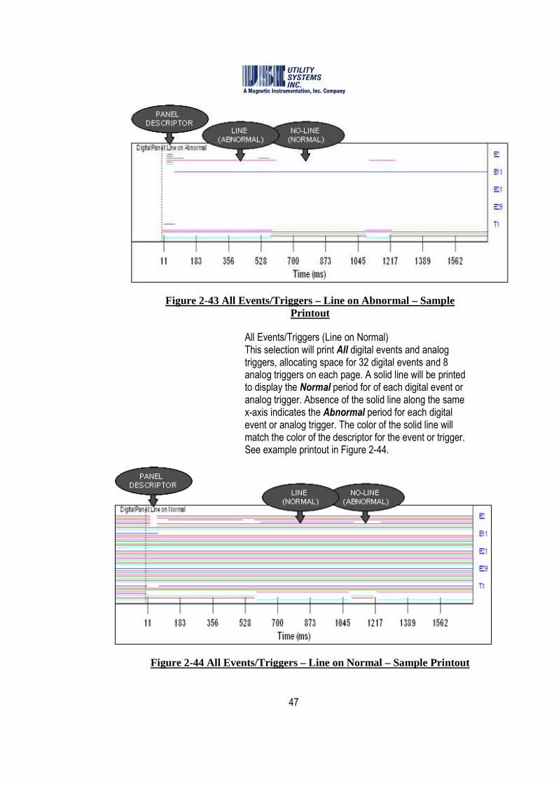
47
Figure 2-43 All Events/Triggers – Line on Abnormal – Sample Printout
� All Events/Triggers (Line on Normal) This selection will print All digital events and analog triggers, allocating space for 32 digital events and 8 analog triggers on each page. A solid line will be printed to display the Normal period for of each digital event or analog trigger. Absence of the solid line along the same x-axis indicates the Abnormal period for each digital event or analog trigger. The color of the solid line will match the color of the descriptor for the event or trigger. See example printout in Figure 2-44.
Figure 2-44 All Events/Triggers – Line on Normal – Sample Printout

48
� Panel Size This field is used to define the default panel height (in percent of printout page height) for the digital events and analog triggers panel. The values are adjustable in steps of 10% from 10% to 90%.
� Font Size Controls
� Font Size Global Control This field is used to assign the default font size which will be applied globally to text characters on the printout.
� Font Size Title Control This field is used to assign the default font size which will be applied specifically to title characters on the printout.
� Annotation Text Size This field is used to assign the default font size which will be applied specifically to annotation characters on the printout.
• Auto Email, Auto Call Master and Auto Print Decision Logic This logic (see Table 2-45 and following examples) is a Boolean equation of analog triggers and digital events and determines whether an Auto-Email, Auto-Call, or Auto-Print action should be carried out, based on which triggers and events were abnormal during each record. This field is used by the DME system to select priority DME records to be processed by the Auto E-mail, Call or Print functions. If this field is left empty the decision logic is interpreted as True and the Auto E-mail, Call and Print functions will be performed on every DME record. Line group logic statements are limited to 200 characters. Spaces are legal characters and are ignored, but they count towards the 200 character limit.

49
Boolean Operators Logic Description & , *, AND AND function
|, +, OR OR function
t1, t2, t3, etc Triggers
e1, e2, e3, etc Events
0 (zero) False, will never pass logic filter
1 True, will always pass logic filter
Nothing (blank) True, will always pass logic filter
Parentheses ( ) Groups logic
Spaces Spaces are ignored by the logic
Table 2-45 Auto Call and Auto Print Decision Logic
Examples: Below are three different syntax samples for the same equation.
(T1|T2|T3|T4|T8|T5|T6|T7) & ((E4 | E5) & E11)
(T1+T2+T3+T4+T8+T5+T6+T7) * ((E4 + E5) * E11)
(T1 OR T2 OR T3 OR T4 OR T8 OR T5 OR T6 OR T7) AND ((E4 OR E5) AND E11)
• �Auto E-mail Check this box to enable the DME system to send an automatic E-mail to all addresses saved in the Recipients field of the E-mail settings screen. The message contains fault summary information of DME records received during Auto-call and Auto-Polling sessions.
����Note: An Ethernet connection is required for the DME system to send an E-mail.
o E-mail Settings This selection displays the Send E-mail window (Figure 2-46). From this window E-mail settings can be customized to define what information is to be sent automatically and to whom. This window can also be used to send an E-mail message manually. The DME system must have an SMTP/POP3 E-mail account and connectivity in order to use the E-mail feature.
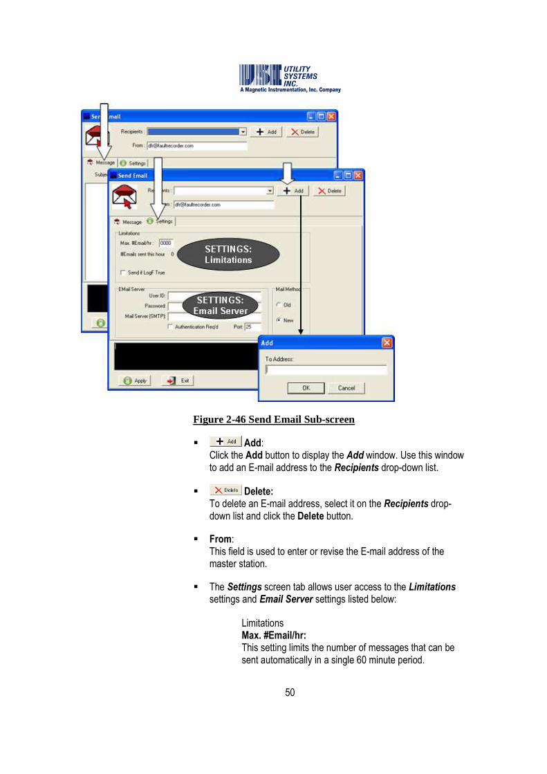
50
Figure 2-46 Send Email Sub-screen
� Add: Click the Add button to display the Add window. Use this window to add an E-mail address to the Recipients drop-down list.
� Delete: To delete an E-mail address, select it on the Recipients drop-down list and click the Delete button.
� From: This field is used to enter or revise the E-mail address of the master station.
� The Settings screen tab allows user access to the Limitations settings and Email Server settings listed below:
� Limitations Max. #Email/hr: This setting limits the number of messages that can be sent automatically in a single 60 minute period.

51
#Emails sent this hour This field displays the number of E-mail messages sent in the current hour.
�Send if LogF True Check this box to apply the Auto Call, Auto Email, and Auto Print decision logic to E-mail messages. E-mail messages will be sent only if this logic is true.
� E-mail Server User ID: This field is used to enter the User ID for the master station E-mail account. Password: This field is used to enter the User Password for the master station E-mail account. If no password is required by the mail server, this field may be left blank. Mail Server (SMTP): This field is used to enter the IP address of the SMTP Mail Server. �Authentication Req’d: This check box allow users to enable authentication, if required by the SMTP Mail Server. Port: This field allows users to enter the port number of the IP address being used for E-mail message transport.
� The Message screen tab is used to send a test E-mail message to the addresses in the Recipients list.
� Subject The Subject field is used to enter a subject for the E-mail message being created manually.
����Note: The subject field of an E-mail message automatically sent by the DME system will
be populated with the Remote ID number and Station Name.
� Message field: This field is used to enter the body of an E-mail message being sent manually.
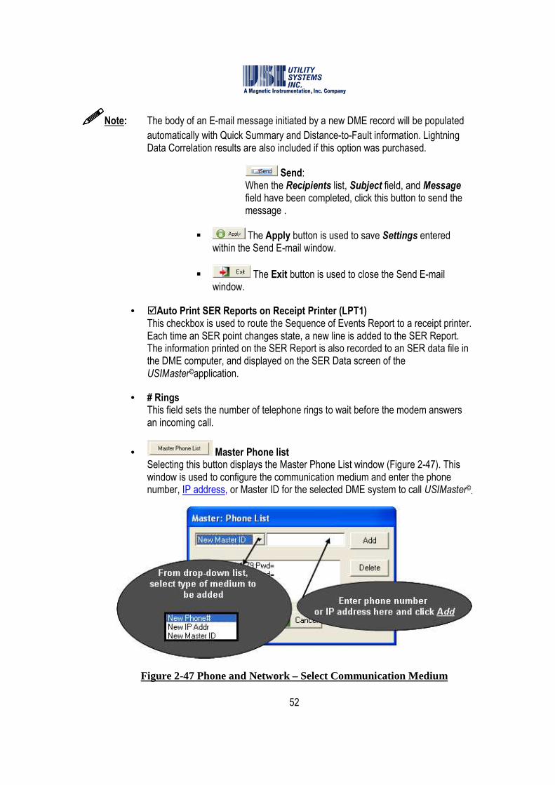
52
����Note: The body of an E-mail message initiated by a new DME record will be populated
automatically with Quick Summary and Distance-to-Fault information. Lightning Data Correlation results are also included if this option was purchased.
� Send: When the Recipients list, Subject field, and Message field have been completed, click this button to send the message .
� The Apply button is used to save Settings entered within the Send E-mail window.
� The Exit button is used to close the Send E-mail window.
• �Auto Print SER Reports on Receipt Printer (LPT1) This checkbox is used to route the Sequence of Events Report to a receipt printer. Each time an SER point changes state, a new line is added to the SER Report. The information printed on the SER Report is also recorded to an SER data file in the DME computer, and displayed on the SER Data screen of the USIMaster©application.
• # Rings This field sets the number of telephone rings to wait before the modem answers an incoming call.
• Master Phone list Selecting this button displays the Master Phone List window (Figure 2-47). This window is used to configure the communication medium and enter the phone number, IP address, or Master ID for the selected DME system to call USIMaster©
.
Figure 2-47 Phone and Network – Select Communication Medium
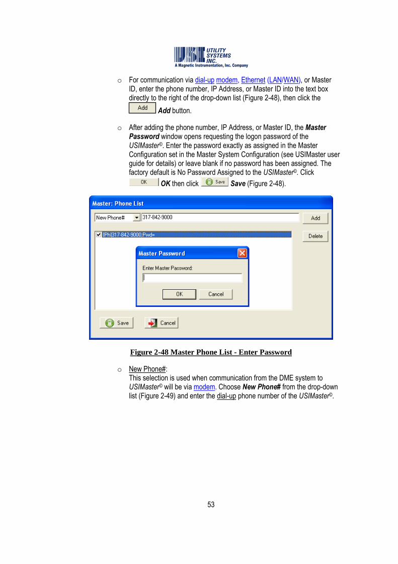
53
o For communication via dial-up modem, Ethernet (LAN/WAN), or Master ID, enter the phone number, IP Address, or Master ID into the text box directly to the right of the drop-down list (Figure 2-48), then click the
Add button.
o After adding the phone number, IP Address, or Master ID, the Master Password window opens requesting the logon password of the USIMaster©. Enter the password exactly as assigned in the Master Configuration set in the Master System Configuration (see USIMaster user guide for details) or leave blank if no password has been assigned. The factory default is No Password Assigned to the USIMaster©. Click
OK then click Save (Figure 2-48).
Figure 2-48 Master Phone List - Enter Password
o New Phone#: This selection is used when communication from the DME system to USIMaster© will be via modem. Choose New Phone# from the drop-down list (Figure 2-49) and enter the dial-up phone number of the USIMaster©.
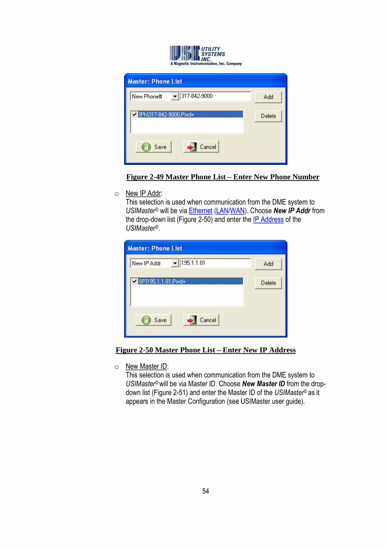
54
Figure 2-49 Master Phone List – Enter New Phone Number
o New IP Addr: This selection is used when communication from the DME system to USIMaster© will be via Ethernet (LAN/WAN). Choose New IP Addr from the drop-down list (Figure 2-50) and enter the IP Address of the USIMaster©.
Figure 2-50 Master Phone List – Enter New IP Address
o New Master ID: This selection is used when communication from the DME system to USIMaster© will be via Master ID. Choose New Master ID from the drop-down list (Figure 2-51) and enter the Master ID of the USIMaster© as it appears in the Master Configuration (see USIMaster user guide).

55
Figure 2-51 Master Phone List – Enter New Master ID
• Password This button is used to assign a communication password to the DME system. Clicking this button displays the WinDFR© Password window (Figure 2-52) used to enter the password for the selected DME system.
Figure 2-52 WinDFR Configuration – WinDFR Password Window
• �Use RFL Switch This checkbox enables selections of an RFL 9660 port switching device from the Choose Modem window (Figure 2-13).
• Memory Watch Tab (Show/Hide) This button is used to show or hide the Memory Options tab on the WinDFR© configuration screen. This screen is hidden by default. When this tab is displayed, the Program Memory Level Options can be modified (Figure 2-14).
2.3.2 WinDFR© Configuration Screen – File Paths/Time Zone
The File Paths/Time Zone screen tab is used to assign the following settings (Figure 2-53).

56
Figure 2-53 WinDFR Configuration Screen - File Paths/Time Zone Tab
• Archive Path This path displays the location where the Transient and Long Term fault records and the Sequence of Events data files are stored on the DME system. The Transient and Long Term records are stored in COMTRADE format. The default path is D:\Comtrade Data Files.
Caution: Modifying the Archive path could cause the DME system to malfunction or go offline. If this path is to be changed, take care to ensure that the new path actually exists on the selected DME system.
• �Back-Up This checkbox is used to enable the automatic data backup function on the DME system. When this box is checked, the Types of records to automatically backup fields are activated.

57
• Back-Up Path This path displays the location where data selected in the Types of records to automatically backup fields will be copied.
• Types of records to backup automatically Click on one or more of the following checkboxes to select types for automatic backup:
o �Quick Summary: Checking this box will cause the DME system to store a copy of the Quick Summary into the Backup Path each time this file is updated.
o �Long Term Oscillography: Checking this box will cause the DME system to store a copy of each Long Term Oscillography file into the Backup Path.
o �Transient Records: Checking this box will cause the DME system to store a copy of each Transient (DFR) record into the Backup Path.
o �Long Term RMS: Checking this box will cause the DME system to store a copy of each Long Term RMS file into the Backup Path.
o �Sequence of Events Data: Checking this box will cause the DME system to store a copy of each SER data file into the Backup Path.
• �Overwrite Old Transient and LT Record checkbox This check box is used to enable the DME system to overwrite the oldest Transient and Long Term fault records from the Archive path. The files are deleted in a first in, first out (FIFO) basis when the Archive disk free space is at 100MB above the Disk Alarm On setting.
Caution: Data files which have been overwritten are permanently deleted and can not be recovered.
• Disk Alarm On if Below xxxxxx Mbytes This setting is used to assign both the activation point for the Disk Full Alarm, and the start level to begin overwriting the oldest Transient and Long Term fault data. The field is a numeric entry in megabytes. When the free space on the archive drive is less than this value, the DISK alarm output relay will be picked up and the DISK FULL LED on the DME system front panel will be illuminated. The default setting is 1024 MB (the equivalent of one gigabyte).

58
• Remote Setup Path This field displays the location where the Calibration Record is stored. This path is also where to store trace files and command files. The Remote program monitors the Setup folder for commands it should execute or records it should update.
• Remote Data Path This field displays the location where WinDFR© polls for new Transient and Long Term fault records and Sequence of Events data. WinDFR© takes these files and executes post-process actions such as adding fault summary information, calculating Distance-to-Fault, executing the Decision Logic.
����Note: After completing these post-processes, the finalized DME record is stored in the
Archive path and the original files from the Remote Data path are deleted.
Caution: Modifying the Remote Setup or Remote Data paths could cause the DME system to malfunction or even to go offline. If this path is to be changed, take care to ensure that the new path actually exists on the selected DME system.
• Fault Recorder Timezone This drop-down list (Figure 2-54) is used to select the time zone for the DME system location. This setting is only applicable when the Lightning Data Corelation© option is used.
Figure 2-54 Fault Recorder Time Zone Menu
• � Auto DST checkbox This checkbox is used to indicate whether or not the DME system clock recognizes automatic Daylight Saving Time (DST) changeovers.
����Note: This setting is used by USIMaster© when the Lightning Data Correlation software
option is being used. The timestamps for lightning strike data are stored in GMT.
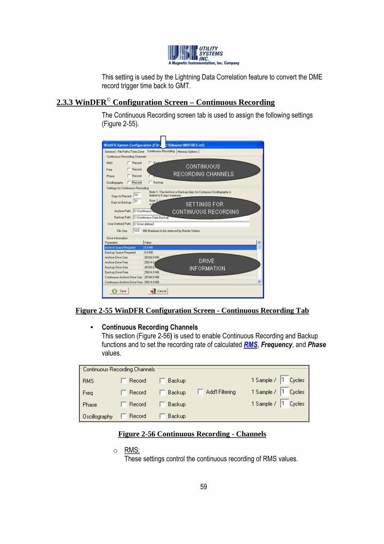
59
This setting is used by the Lightning Data Correlation feature to convert the DME record trigger time back to GMT.
2.3.3 WinDFR© Configuration Screen – Continuous Recording
The Continuous Recording screen tab is used to assign the following settings (Figure 2-55).
Figure 2-55 WinDFR Configuration Screen - Continuous Recording Tab
• Continuous Recording Channels This section (Figure 2-56) is used to enable Continuous Recording and Backup functions and to set the recording rate of calculated RMS, Frequency, and Phase values.
Figure 2-56 Continuous Recording - Channels
o RMS: These settings control the continuous recording of RMS values.
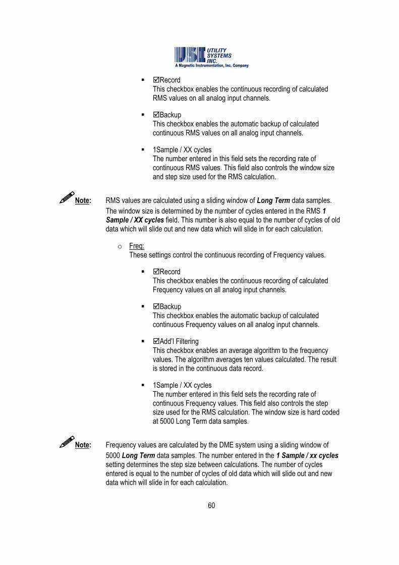
60
� �Record This checkbox enables the continuous recording of calculated RMS values on all analog input channels.
� �Backup This checkbox enables the automatic backup of calculated continuous RMS values on all analog input channels.
� 1Sample / XX cycles The number entered in this field sets the recording rate of continuous RMS values. This field also controls the window size and step size used for the RMS calculation.
����Note: RMS values are calculated using a sliding window of Long Term data samples.
The window size is determined by the number of cycles entered in the RMS 1 Sample / XX cycles field. This number is also equal to the number of cycles of old data which will slide out and new data which will slide in for each calculation.
o Freq: These settings control the continuous recording of Frequency values.
� �Record This checkbox enables the continuous recording of calculated Frequency values on all analog input channels.
� �Backup This checkbox enables the automatic backup of calculated continuous Frequency values on all analog input channels.
� �Add’l Filtering This checkbox enables an average algorithm to the frequency values. The algorithm averages ten values calculated. The result is stored in the continuous data record.
� 1Sample / XX cycles The number entered in this field sets the recording rate of continuous Frequency values. This field also controls the step size used for the RMS calculation. The window size is hard coded at 5000 Long Term data samples.
����Note: Frequency values are calculated by the DME system using a sliding window of
5000 Long Term data samples. The number entered in the 1 Sample / xx cycles setting determines the step size between calculations. The number of cycles entered is equal to the number of cycles of old data which will slide out and new data which will slide in for each calculation.
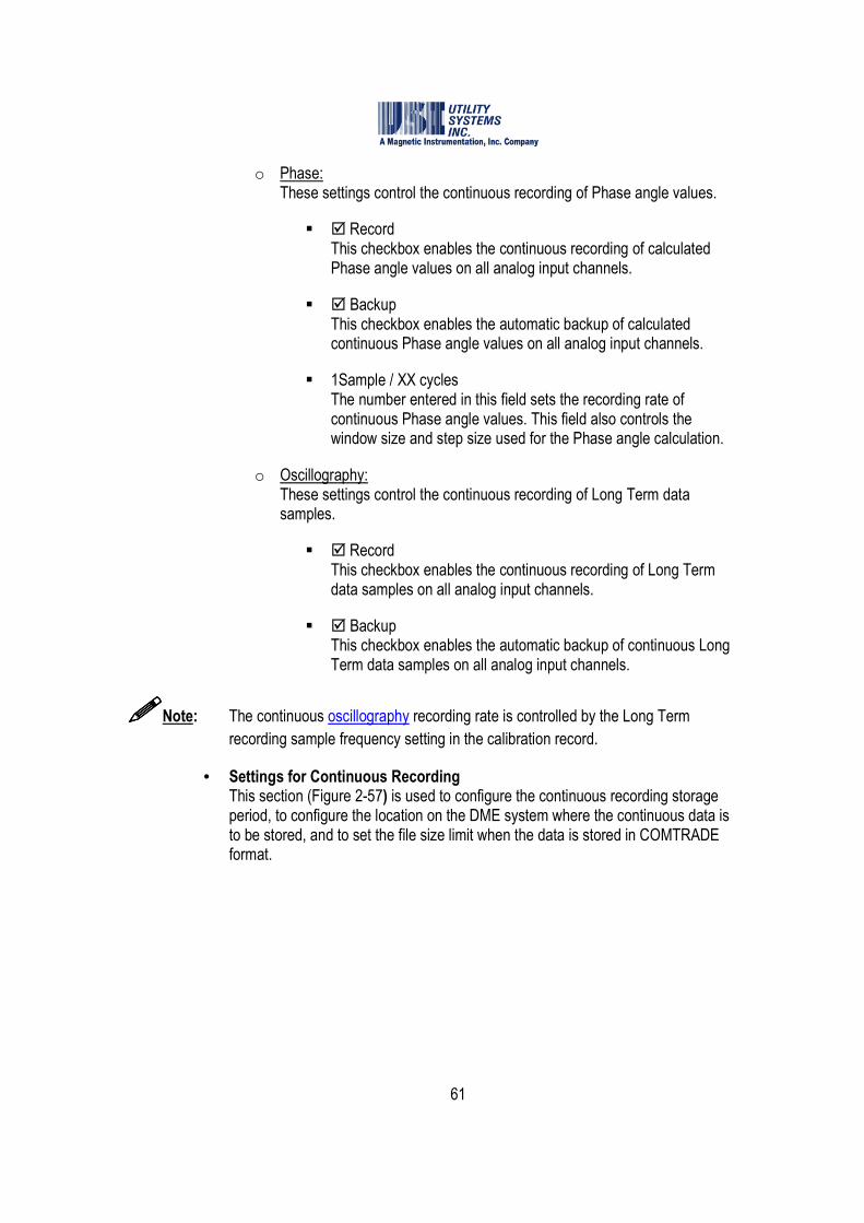
61
o Phase: These settings control the continuous recording of Phase angle values.
� � Record This checkbox enables the continuous recording of calculated Phase angle values on all analog input channels.
� � Backup This checkbox enables the automatic backup of calculated continuous Phase angle values on all analog input channels.
� 1Sample / XX cycles The number entered in this field sets the recording rate of continuous Phase angle values. This field also controls the window size and step size used for the Phase angle calculation.
o Oscillography: These settings control the continuous recording of Long Term data samples.
� � Record This checkbox enables the continuous recording of Long Term data samples on all analog input channels.
� � Backup This checkbox enables the automatic backup of continuous Long Term data samples on all analog input channels.
����Note: The continuous oscillography recording rate is controlled by the Long Term
recording sample frequency setting in the calibration record.
• Settings for Continuous Recording This section (Figure 2-57) is used to configure the continuous recording storage period, to configure the location on the DME system where the continuous data is to be stored, and to set the file size limit when the data is stored in COMTRADE format.

62
Figure 2-57 Continuous Recording - Settings
o Days to Record: The number entered in this field sets the number of days continuous data is to be stored in the continuous Archive Path. A maximum of 91 days is allowed for RMS, Frequency and Phase.
o Days to Backup: The number entered in this field sets the number of days continuous data is to be stored in the continuous Backup Path. A maximum of 91 days is allowed for RMS, Frequency and Phase.
����Note: Recording and backup of continuous oscillography is limited to 6 days maximum.
o Archive Path: This directory path specifies the location where Continuous Recording values will be stored on the DME system.
o Backup Path: This directory path specifies the location where Continuous Recording values will be copied onto the DME system when the backup checkbox is selected.
����Note: The continuous Backup Path must be set to a different drive from the Archive
Path to enable the Backup checkboxes. When a Backup checkbox is selected, the total amount of available continuous data will be equal to the sum of the Days to Record and Days to Backup settings.
o User Defined Path: This directory path specifies a location where Continuous Recording values can be copied when the Schedule Continuous Backup feature is used in USIMaster©.
63
o File Size XX Maximum to be retrieved by Master Station: This field is used to set the maximum continuous COMTRADE data file size. This value can be adjusted from 1.2MB to 100MB.
����Note: When Continuous Data is selected, the data is saved in a single COMTRADE
formatted data file with the exception that the data file size is extended to the number entered here.
COMTRADE format, as specified in the standard, limits the size of a data file to 1.2MB. Without this feature, if the amount of data being saved is greater than 1.2MB, multiple data files must be created, each limited to 1.2MB in size. Since the DME system contains several days of continuous data, retaining the COMTRADE standard could easily create numerous 1.2MB data files.
• Drive Information This section (Figure 2-58) displays calculated disk storage requirements based on the selections made in the Continuous Recording Channels and Settings for Continuous Recording sections.
Figure 2-58 Continuous Recording – Drive Information
o Archive Space Required: This value displays the disk space required for archiving. It is a calculated value based on the recording selections made in the Continuous Recording Channels section.
o Backup Space Required: This value displays the disk space required for backup. It is a calculated value based on the backup selections made in the Continuous Recording Channels section.
o Archive Drive Size: This value displays the size of the transient recording archive drive.
64
o Archive Drive Free: This value displays the available free space on the transient recording archive drive.
o Backup Drive Size: This value displays the size of the transient recording backup drive.
o Backup Drive Free: This value displays the available free space on the transient recording backup drive.
o Continuous Archive Drive Size: This value displays the size of the continuous recording archive drive.
o Continuous Archive Drive Free: This value displays the available free space on the continuous recording archive drive.
o Continuous Backup Drive Size: This value displays the size of the continuous recording backup drive.
o Continuous Backup Drive Free: This value displays the available free space on the continuous recording backup drive.
2.3.4 WinDFR© Configuration Screen – Memory Options
The contents of the WinDFR© Configuration – Memory Options Tab screen (Figure 2-59) are outlined below:

65
Figure 2-59 WinDFR© Configuration Screen – Memory Options Tab
����Note: The Memory Options screen is hidden by default. It is visible only after the
Memory Watch Tab Show button (Figure 2-30) has been selected.
When selected, this button toggles between Show and Hide.
Caution: Modifying these settings could cause the DME system to become unstable or to go offline.
• Program Memory Level Options WinDFR© has a memory watch-dog which monitors the DME system memory usage. It initiates an action as defined below when available memory drops below the specified limit.
o If Physical Memory drops below xx% If available Physical Memory drops below this limit, an action will be taken. The limit is set in this field and the action is set in the drop-down list. The default limit is 5%; the default action is Reboot System.
o If Page File Memory drops below xx% If available Page File Memory drops below this limit, an action will be
66
taken. The limit is set in this field and the action is set in the drop-down list. The default limit is 10%; the default action is Restart WinDFR© Program.
o If Virtual Memory drops below xx% If available Virtual Memory drops below this limit, an action will be taken. The limit is set in this field and the action is set in the drop-down list. The default limit is 10%; the default action is No Action.
o Action: One of the following actions can be selected for each of the above conditions:
� No Action This selection will cause No Action to be taken when the limit condition is reached.
� Restart WinDFR© Program This selection will restart WinDFR© when the limit condition is reached.
� Reboot System This selection will reboot the DME system when the limit condition is reached.
o Do a memory check per: This drop-down list is used to select the time interval between memory checks. When the selected time limit is reached, available levels of Physical Memory, Page File Memory, and Virtual Memory are logged into the WinDFR© trace file and the above memory watch-dog actions are taken. Default time interval is one (01) hour.
o (If a modem is used) Check Modem per: This drop-down list is used to select the time interval between modem checks. During a modem check, WinDFR© verifies that the dial-up modem is responding. Default check interval is 24 hours.
2.4 Calibration Record
The Edit Calibration Record window can be opened for editing or review by clicking on the Edit menu and selecting it from the Calibration Record menu. This window consists of Calibration Record header, Station header, and Screen Select tabs (Figure 2-60).
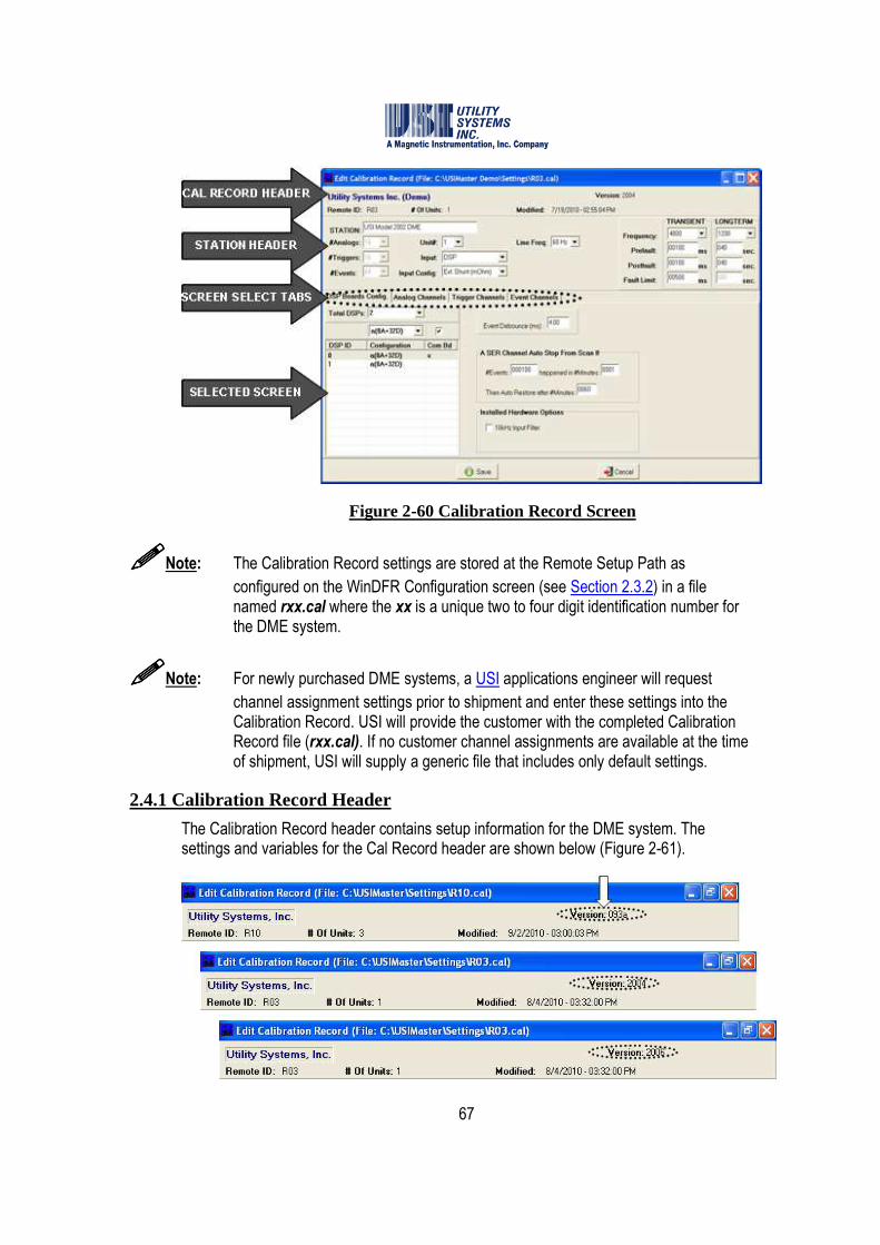
67
Figure 2-60 Calibration Record Screen
����Note: The Calibration Record settings are stored at the Remote Setup Path as
configured on the WinDFR Configuration screen (see Section 2.3.2) in a file named rxx.cal where the xx is a unique two to four digit identification number for the DME system.
����Note: For newly purchased DME systems, a USI applications engineer will request
channel assignment settings prior to shipment and enter these settings into the Calibration Record. USI will provide the customer with the completed Calibration Record file (rxx.cal). If no customer channel assignments are available at the time of shipment, USI will supply a generic file that includes only default settings.
2.4.1 Calibration Record Header
The Calibration Record header contains setup information for the DME system. The settings and variables for the Cal Record header are shown below (Figure 2-61).

68
Figure 2-61 Calibration Record Header Versions
• Company Name This field displays the Company Name as configured in the WinDFR System Configuration file (see Section 2.3.1).
• Version This field displays the version of Calibration Record as 093a, 2004, or 2006. To convert the Calibration Records from V2004 to V2006 right-click anywhere in the Cal Record Header and select Convert to 2004/2006. V093a can not be converted to other format versions.
o Calibration Record – Version 093a This format version of the Calibration Record is used for the Model HT/LT2000W Digital Fault Recorder only.
o Calibration Record – Version 2004: This format version of the Calibration Record is used for any Model 2002 DME system running any version of USIRemote© software.
o Calibration Record – Version 2006: This format version of the Calibration Record is used for any Model 2002 DME system running USIRemote© V3.1.0 software or later.
• Remote ID This field displays the unique identification number for the selected DME system.
• # Of Units This field displays the number of units (1 to 4) that makes up the selected DME system. If this number is greater than one (1), multiple discreet HT/LT2000W units have been cascaded together to assemble the overall DFR system. This is done when either the total number of inputs needed exceeds the maximum available on a single-unit system or when the location requires distributing units in different locations within a substation or power plant.
• Modified This field displays the date and time of the DME computer when Modified Date-Time was last updated. Users are prompted to update the Modified Date-Time when saving the Calibration Record.
• Save This selection is used to save all setting changes made on any screen tab and to close the Edit Calibration Record window. When the Save button is selected, the Modified Date-Time window displays. Selecting Yes will update the Modified field in the Calibration Record header to the WinDFR PC time. This feature is useful in tracking when changes were made
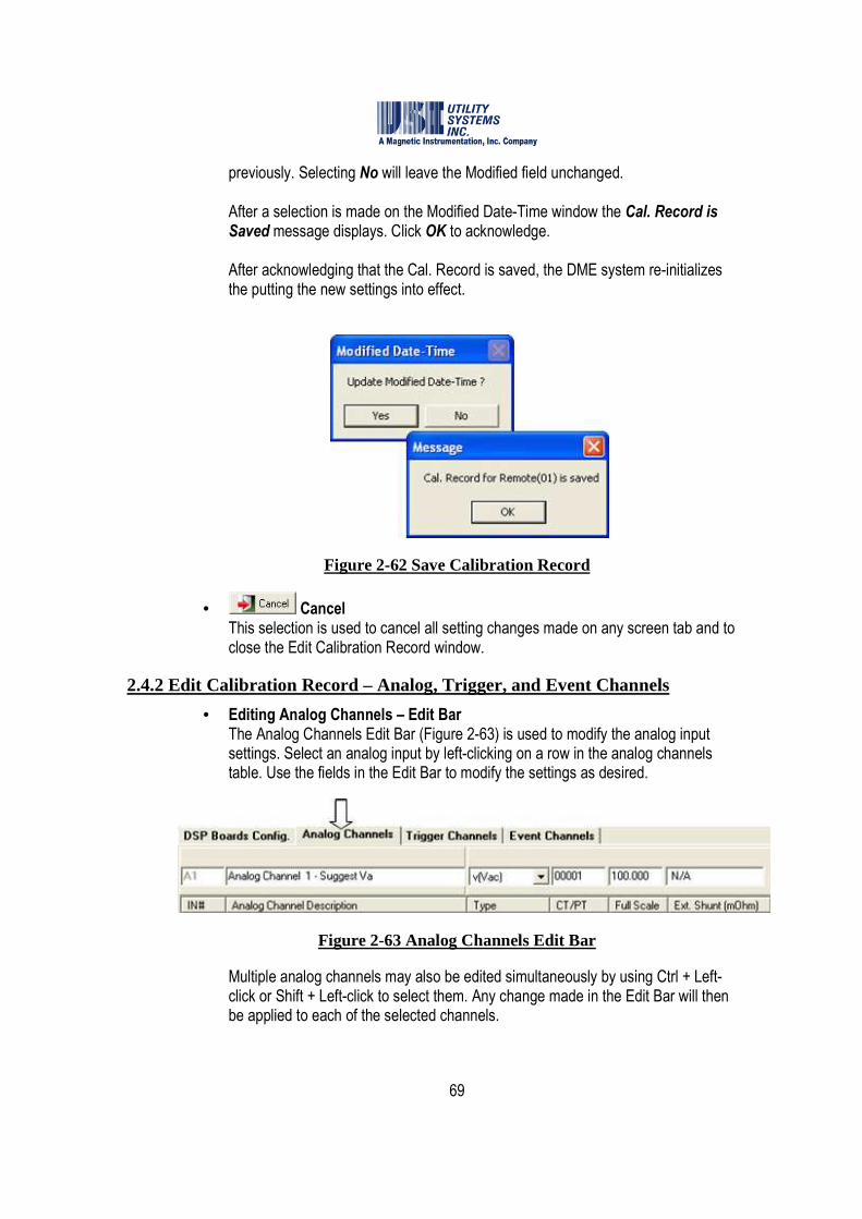
69
previously. Selecting No will leave the Modified field unchanged. After a selection is made on the Modified Date-Time window the Cal. Record is Saved message displays. Click OK to acknowledge. After acknowledging that the Cal. Record is saved, the DME system re-initializes the putting the new settings into effect.
Figure 2-62 Save Calibration Record
• Cancel This selection is used to cancel all setting changes made on any screen tab and to close the Edit Calibration Record window.
2.4.2 Edit Calibration Record – Analog, Trigger, and Event Channels
• Editing Analog Channels – Edit Bar The Analog Channels Edit Bar (Figure 2-63) is used to modify the analog input settings. Select an analog input by left-clicking on a row in the analog channels table. Use the fields in the Edit Bar to modify the settings as desired.
Figure 2-63 Analog Channels Edit Bar
Multiple analog channels may also be edited simultaneously by using Ctrl + Left-click or Shift + Left-click to select them. Any change made in the Edit Bar will then be applied to each of the selected channels.

70
o Analog Channels Edit Bar – Right-click menu Right-click anywhere on the Analog Channels Edit Bar to display the right-click menu (Figure 2-64). This menu displays standard editing tools. These edit tools can also be accessed through standard keystrokes (e.g. Ctrl + Z = Undo, Ctrl + X = Cut, etc.).
Figure 2-64 Analog Channels Edit Bar –Right-click Menu
o Analog Channels Table – Right-click menu Right-click anywhere on the Analog Channels table to display this menu (Figure 2-65).
Figure 2-65 Calibration Record Analog Channels –Right-click Menu
� Select All This selection will highlight all the rows in the Analog Channel table.
� Paste Description (only) from Clipboard This selection will paste descriptions from the WindowsTM clipboard into the description fields for the selected analog channels.
����Note: Analog Channel descriptions can be copied in bulk from an MS Excel worksheet.
Highlight and copy the descriptions on the spreadsheet to place them on the WindowsTM clipboard. Click Select All from the Analog Channels right-click menu and then click Paste Description (only) from Clipboard.
• Editing Trigger Channels – Edit Bar The Trigger Channels Edit Bar (Figure 2-66) is used to modify the analog trigger settings. Select a trigger by left-clicking on a row in the Trigger Channels table. Use the fields in the Edit Bar to modify the settings as desired.

71
Figure 2-66 Trigger Channels Edit Bar
Multiple analog channels may also be edited simultaneously by using Ctrl + Left-click or Shift + Left-click to select them. Any change made in the Edit Bar will then be applied to each of the selected channels.
o Trigger Channels Edit Bar – Right-click menu Right-click anywhere on the Trigger Channels Edit Bar to display the right-click menu (Figure 2-67). This menu displays standard editing tools. These edit tools can also be accessed through standard keystrokes (e.g. Ctrl + Z = Undo, Ctrl + X = Cut, etc.).
Figure 2-67 Trigger Channels Edit Bar –Right-click Menu
o Trigger Channels Table – Right-click menu Right-click anywhere on the Trigger Channels table to display this menu (Figure 2-68).
Figure 2-68 Calibration Record Trigger Channels – Right-click Menu
� Select All This selection will highlight all the rows in the Trigger Channel table.

72
� Update Trig. Chan. Desc. This function displays only for version 093a. This selection replaces the trigger channel description with the analog channel description.
� Replace Trig. Chan. Desc. With Analog Chan. Desc. This function displays only for versions 2004 & 2006. This selection replaces the trigger channel description with the analog channel description.
� Paste Description (only) from Clipboard This selection will paste descriptions from the WindowsTM clipboard into the description fields for the selected trigger channels.
����Note: Trigger Channel descriptions can be copied in bulk from an MS Excel worksheet.
Highlight and copy the descriptions on the spreadsheet to place them on the WindowsTM clipboard. Click Select All from the Trigger Channels right-click menu and then click Paste Description (only) from Clipboard.
• Editing Event Channels – Edit Bar The Event Channels Edit Bar (Figure 2-69) is used to modify the event settings. Select an event by left-clicking on a row in the event channels table. Use the fields in the Edit Bar to modify the settings as desired.
Figure 2-69 Event Channels Edit Bar
Multiple event channels may also be edited simultaneously by using Ctrl + Left-click or Shift + Left-click to select them. Any change made in the Edit Bar will then be applied to each of the selected channels.
o Event Channels Edit Bar – Right-click menu Right-click anywhere on the Event Channels Edit Bar to display the right-click menu (Figure 2-70). This menu displays standard editing tools. These edit tools can also be accessed through standard keystrokes (e.g. Ctrl + Z = Undo, Ctrl + X = Cut, etc.).

73
Figure 2-70 Event Channels Edit Bar –Right-click Menu
o Event Channels Table – Right-click menu Right-click anywhere on the Event Channels table to display this menu (Figure 2-71).
Figure 2-71 Calibration Record Event Channels – Right-click Menu
� Select All This selection will highlight all the rows in the Event Channel table.
� Paste Description (only) from Clipboard This selection will paste descriptions from the WindowsTM clipboard into the description fields for the selected trigger channels.
� Copy Normal Event Descripts to Alt Descripts This selection replaces the alternate event descriptions with the normal event channel descriptions.
� Auto Assign Alt Descripts This selection appends the suffix Abnormal to the event alternate event channel descriptions.
����Note: Event Channel descriptions can be copied in bulk from an MS Excel worksheet.
Highlight and copy the descriptions on the spreadsheet to place them on the WindowsTM clipboard. Click Select All from the Event Channels right-click menu and then click Paste Description (only) from Clipboard.

74
2.4.3 Edit Calibration Record Version 093a
The format version 093a Calibration Record applies to the Model HT/LT2000W Digital Fault Recorder only.
• Station Header The Station Header section is used to assign the following settings (Figure 2-72).
Figure 2-72 Calibration Record Station Header –Version 093a
o Station: This field is used to enter the alpha-numeric station name. The name is limited to 32 characters.
o #Analogs: This drop-down menu is used to select the number of analog input channels available for the selected Unit of the DFR system. Analog channels on the Model HT/LT2000W system are selectable in multiples of 16 from 16 to 64.
o #Triggers: This drop-down menu is used to select the number of analog triggers available for the selected Unit of the DFR system. Analog triggers on the Model HT/LT2000W system are selectable in multiples of four from 4 to 48.
o #Events: This drop-down menu is used to select the number of digital event inputs available for the selected Unit of the DFR system. Event inputs on the Model HT/LT2000W system are selectable in multiples of eight from 8 to 128.
75
o Unit #: This drop-down menu is used to select the specific Unit number of the DFR system to be displayed. The number of units can range from 1 to 4 depending on the selection made when the Calibration Record was initially created in USIMaster©.
o Input: This field displays the type of analog-to-digital converter used on the input cards for Model HT/LT2000W systems, or to select DSP for Model 2002 systems. This setting informs the DFR or DME system which routine to use when reading the analog data.
� ADC84: This selection specifies that the analog-to-digital converter used on the analog input boards is the ADC84 family.
� ADS7800: This selection specifies that the analog-to-digital converter used on the analog input boards is the ADS7800 family without sample-and-hold capability.
� ADS7800 + SHC: This selection specifies that the analog-to-digital converter used on the analog input boards is the ADS7800 family with sample-and-hold capability.
����Note: The Model HT/LT2000W system utilizes a single Analog-to-Digital converter chip
per 16 analog channels. All sixteen channels are multiplexed through the same converter. Sample-and-Hold technology is used to eliminate time skew between channels.
� DSP: This selection specifies that the system is a Model 2002 DME system and converts the Calibration Record to version 2004 or 2006.
o Input Config: This drop-down menu is used to select the analog input configuration. This selection changes the last column title on the Analog Channels screen to the selected Input Config. The choices are: Calibration Ratio or Ext. Shunt (mOhm).
� Calibration Ratio: This selection enables a multiplier to be applied to analog channel sampled values. This multiplier setting is entered in the

76
Calibration Ratio column on the Analog Channels screen. The default multiplier setting is one (1).
� Ext. Shunt (mOhm): This selection is used to indicate that the current-measuring analog inputs are receiving signals from an external shunt or auxiliary CT device as opposed to the system internal shunt. The actual value of the external shunt or the equivalent shunt value of the auxiliary CT device may be entered in mOhms (milliohms) into the Ext. Shunt (mOhm) column on the Analog Channels screen tab.
o Line Freq: In Calibration Record version 093a this field displays 60 Hz only. The Model HT/LT2000W system is compatible only with 60 Hz power systems. In Calibration Record versions 2004 and 2006 this field drop-down menu displays 50 Hz and 60 Hz.
o Frequency: These drop-down menus are used to select the TRANSIENT and LONG TERM sampling frequencies (samples per second) at which the DFR analog-to-digital converters operate.
� TRANSIENT: For systems having 16 or 32 analog input channels available sample rate selections are 1200Hz, 2400Hz, 4800Hz, or 9600Hz. Systems having 48 or 64 analog input channels are limited to sample rate selections of 1200Hz, 2400Hz, or 4800Hz. This sampling frequency is applied to the analog inputs only. The sampling frequency of the analog triggers and the digital inputs is fixed at 1000Hz.
� LONGTERM: Sample rate selections available from this drop-down menu are 0Hz (Disables Long Term recording), 240Hz, 600Hz, or 1200Hz.
o Pre-Fault: This setting determines the period of prefault data that the DFR will record prior to the actual trigger event. This value is set for both the Transient and Long Term recorders. Transient record Pre-Fault can be set to a maximum of 10 seconds. Long term Pre-Fault can be set to a maximum of 990 seconds.
o Post-Fault: This setting determines the period of Post-Fault data that the DFR will record after the triggers and events clear, or the Fault Limit period has elapsed. This value is set for both the Transient and Long Term recorders.

77
Transient Post-Fault can be set to a maximum of 10 seconds. Long Term Post-Fault can be set to a maximum of 990 seconds.
o Fault Limit: This setting determines the time limit of any record. This value is set for both Transient and Long-Term recorders. Transient Fault-Limit may be set for a maximum of 10 seconds. Long term Fault-Limit is not applicable.
����Note: The total length of a fault record is equal to (Pre-Fault period) + (Fault period) +
Post-Fault period). If an analog or digital trigger should re-occur during the Post-Fault period, the fault record will be extended to contain the entire event in a single COMTRADE data file. The maximum length of a Fault Record in a re-trigger situation is 40 seconds.
• Analog Channels (Version 093a) The Analog Channels section is used to assign the following settings (Figure 2-73).
Figure 2-73 Calibration Record Analog Channels –Version 093a
o IN#: This column displays the analog channel number for each physical input.
o Analog Channel Description: This column displays the alpha-numeric description entered for each analog input. The analog channel description is limited to 80 characters.
o Type: This column displays the channel type selected for each analog input:
78
� v(Vac): This selection indicates that the analog input is monitoring an AC voltage signal.
� V(Vdc): This selection indicates that the analog input is monitoring a DC voltage signal.
� c(Aac-Reg): This selection indicates that the analog input is monitoring an AC current signal measured by an internal current shunt. This input type connects to the HT/LT2000W system between the I and C terminals.
� c(Aac-Shunt): This selection indicates that the analog input is monitoring an AC current signal by measuring the voltage output of an external current shunt or an auxiliary current transformer device.
� C(Adc-Reg): This selection indicates that the analog input is monitoring a DC current signal measured by an internal current shunt. This input type connects to the HT/LT2000W system between the I and C terminals.
� C(Adc-Shunt): This selection indicates that the analog input is monitoring a DC current signal by measuring the voltage output of a current shunt or an external current transformer device.
� f(Hz): This selection indicates that the analog input is monitoring frequency by measuring the DC voltage output of a transducer external to the system.
� w(MWatt): This selection indicates that the analog input is monitoring megawatts by measuring the DC voltage output of a transducer external to the system.
� q(MVar): This selection indicates that the analog input is monitoring Mega-VARs by measuring the DC voltage output of a transducer external to the system.
79
����Note: This note applies to all inputs measuring AC or DC voltage signals directly from
potential transformers, voltage outputs from external shunts or auxiliary CT devices, and voltage output from transducers. If the full scale voltage range being measured is less than or equal to 40V(rms), this input type connects to the HT/LT2000W system between the V2 and C terminals. If the full scale voltage range being measured is greater than 40V(rms), this input type connects to the HT/LT2000W system between the V1 and C terminals.
o CT/PT: This column displays the Current Transformer or Potential Transformer ratio for each analog input. This setting is the ratio of primary to secondary transformer turns (e.g. an entry of 240 indicates a ratio of 240:1).
o Full Scale: This column displays the highest input level expected to be applied to the HT/LT2000W system at the input terminals.
����Note: Care should be taken when selecting full scale levels. Setting this value too low
will result in clipping; conversely, setting this value too high will result in reduced accuracy of low level readings.
����Note: After changing full scale levels on a Model HT/LT2000W system, re-calibration of
the modified channels is required.
o Calibration Ratio / Ext. Shunt (mOhm): This column title is determined by the setting previously made from the Input Configuration drop-down list on the station header.
� Calibration Ratio This column displays a multiplier that is applied to the measured data. Primary values for analog channels are calculated as follows: [measured input value] x [CAL Ratio] x [CT/PT Ratio]. The default setting for this column is one (1).
� Ext. Shunt (mOhm) This column displays the value, in milliohms, of the external shunt resistor or the equivalent shunt value of an auxiliary current transformer device. The system uses these stored resistance values to convert sensed voltages to their equivalent line currents (R = E ÷ I ).

80
• Trigger Channels (Version 093a) The Trigger Channels section (Figure 2-74) is used to assign the following settings:
Figure 2-74 Calibration Record Trigger Channels –Version 093a
o TR#: This column displays the analog trigger numbers available to be assigned to an analog channel.
o IN#: This column displays the analog channel number assigned to an analog trigger.
o Trigger Channel Description: This column displays the alpha-numeric description entered for each trigger channel. The trigger channel description is limited to 80 characters. This descriptor will display in the Events/Triggers Tripped column of the Quick Summary and History Data screens. It can be exactly the same as the Analog Channel description or it can be tailored to identify the analog trigger more specifically (e.g. adding harmonic, frequency, etc., to identify specifically the unit that this trigger is monitoring).
o Type: This column displays the trigger type that is applied to each analog input.
� d(Disabled) This selection prevents the trigger from initiating a recording.
� o(Over V) This selection enables the analog trigger to initiate a recording if the RMS voltage level of the analog input is equal to or greater than the value assigned in the Trip if Over column.

81
� u(Under V) This selection enables the analog trigger to initiate a recording if the RMS voltage level of the analog input is less than the value assigned in the Trip if Under column.
� b(Both V) This selection enables the analog trigger to initiate a recording if the RMS voltage level of the analog input is either less than the value assigned in the Trip if Under column or equal to or greater than the value assigned in the Trip if Over column.
� i(Over A) This selection enables the selected analog trigger to initiate a recording if the RMS current level of the analog input is equal to or greater than the value assigned in the Trip if Over column.
� h(High Hz) This selection enables the selected analog trigger to initiate a recording if the frequency of the analog input is equal to or greater than the value assigned in the Trip if Over column.
� l(Low Hz) This selection enables the selected analog trigger to initiate a recording if the frequency of the analog input is less than the value assigned in the Trip if Under column.
� f(Both Hz) This selection enables the selected analog trigger to initiate a recording if the frequency of the analog input is less than the value assigned in the Trip if Under column or equal to or greater than the value assigned in the Trip if Over column.
� z(Zero Seq.) This selection enables the selected analog trigger to initiate a recording if the zero sequence level of the analog input is equal to or greater than the value assigned in the Trip if Over column.
o Start: This column is not applicable to the Model HT/LT2000W system. This column applies only to the Model 2002 DME system and is activated only in Calibration Record versions 2004 and 2006.
o Duration: This column is not applicable to the Model HT/LT2000W system. This column applies only to the Model 2002 DME system and is activated only in Calibration Record versions 2004 and 2006.
82
o Trip if Over: This column displays the level at which an over voltage, over current, over frequency, or over zero sequence trigger will initiate a recording.
o Trip if Under: This column displays the level at which an under voltage, under current, or under frequency trigger will initiate a recording.
o Trip if Rate > x/s: This column is not applicable to the Model HT/LT2000W system. This column applies only to the Model 2002 DME system and is activated only in Calibration Record versions 2004 and 2006.
o Normal Value: This column displays the level designated to be the normal or expected signal level. The values in this column are not used by the analog triggers and are for reference only. Entries into this column are not required.
o Priority: This column displays the priority trigger setting.
� no Analog triggers with Priority set to no will be limited to a recording assigned by the Fault Limit setting.
� yes Analog triggers with Priority set to yes will not limit recordings to the Fault Limit setting and will allow recording to continue as long as that trigger is in an abnormal condition or until the system memory fills up.
Caution: Do NOT enable Priority on under-voltage or under-frequency analog triggers. If the circuit being monitored is taken out of service, the persistent under-voltage and under-frequency conditions will create excessively long data records. These records could fill the memory and cause the system to malfunction.
• Event Channels (Version 093a) The Event Channels section (Figure 2-75) is used to assign the following settings:
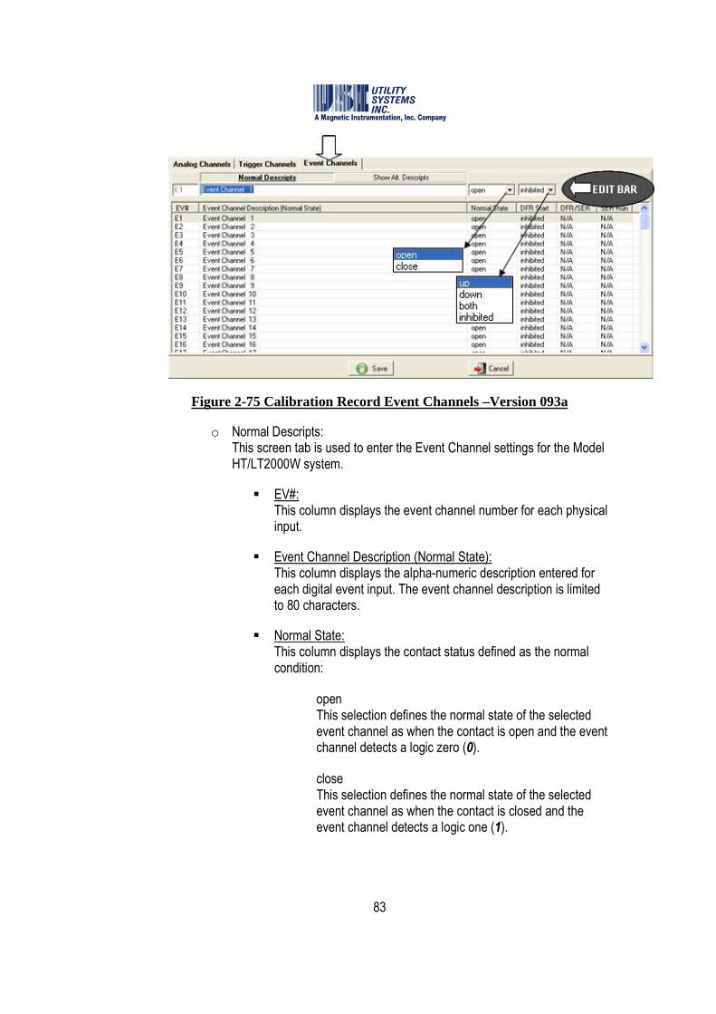
83
Figure 2-75 Calibration Record Event Channels –Version 093a
o Normal Descripts: This screen tab is used to enter the Event Channel settings for the Model HT/LT2000W system.
� EV#: This column displays the event channel number for each physical input.
� Event Channel Description (Normal State): This column displays the alpha-numeric description entered for each digital event input. The event channel description is limited to 80 characters.
� Normal State: This column displays the contact status defined as the normal condition:
� open This selection defines the normal state of the selected event channel as when the contact is open and the event channel detects a logic zero (0).
� close This selection defines the normal state of the selected event channel as when the contact is closed and the event channel detects a logic one (1).

84
� DFR Start: This column displays the conditions under which an event channel initiates a recording:
� up This selection indicates that the selected event channel initiates a recording on the rising edge of a state change (transition from logic zero (0) to logic one (1).
� down This selection indicates that the selected event channel initiates a recording on the falling edge of a state change (transition from logic one (1) to logic zero (0).
� both This selection indicates that the selected event channel initiates a recording on either the rising edge or falling edge of a state change (transition from logic 0 to logic 1 or transition from logic 1 to logic 0).
� inhibited This selection indicates that the selected event channel is disabled from initiating a recording. The status of these event channels will be recorded when a recording is initiated by another event channel or analog trigger channel, but the selected event channel can not initiate a recording itself.
����Note: On the Model HT/LT2000W system, the DFR Start column does not directly
control the trigger function of the event channels. The eight-channel Event Board contains two eight-position DIP switches which actually control the trigger functions. See the HT/LT2000W Users Guide for details.
� DFR/SER: This column is not applicable to the Model HT/LT2000W system. This column applies only to the Model 2002 DME system and is activated only in Calibration Record versions 2004 and 2006.
� SER Run: This column is not applicable to the Model HT/LT2000W system. This column applies only to the Model 2002 DME system and is activated only in Calibration Record versions 2004 and 2006.
o Show Alt. Descripts: This screen tab is not applicable to the Model HT/LT2000W system.
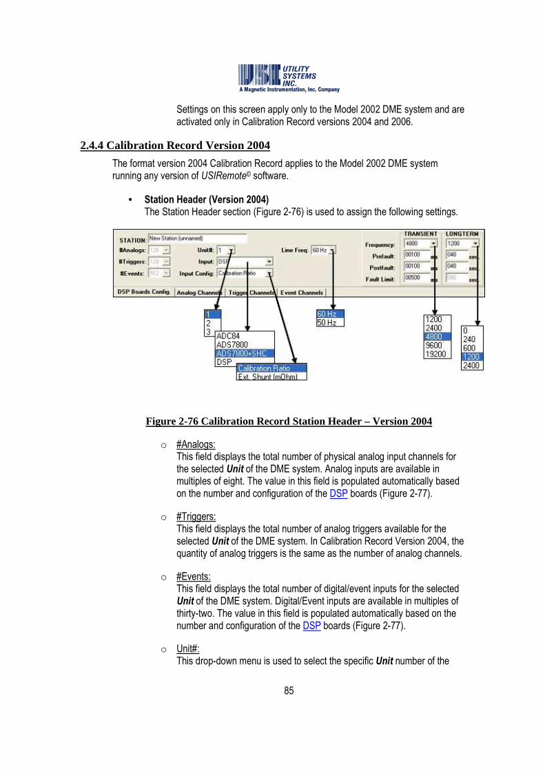
85
Settings on this screen apply only to the Model 2002 DME system and are activated only in Calibration Record versions 2004 and 2006.
2.4.4 Calibration Record Version 2004
The format version 2004 Calibration Record applies to the Model 2002 DME system running any version of USIRemote© software.
• Station Header (Version 2004) The Station Header section (Figure 2-76) is used to assign the following settings.
Figure 2-76 Calibration Record Station Header – Version 2004
o #Analogs: This field displays the total number of physical analog input channels for the selected Unit of the DME system. Analog inputs are available in multiples of eight. The value in this field is populated automatically based on the number and configuration of the DSP boards (Figure 2-77).
o #Triggers: This field displays the total number of analog triggers available for the selected Unit of the DME system. In Calibration Record Version 2004, the quantity of analog triggers is the same as the number of analog channels.
o #Events: This field displays the total number of digital/event inputs for the selected Unit of the DME system. Digital/Event inputs are available in multiples of thirty-two. The value in this field is populated automatically based on the number and configuration of the DSP boards (Figure 2-77).
o Unit#: This drop-down menu is used to select the specific Unit number of the
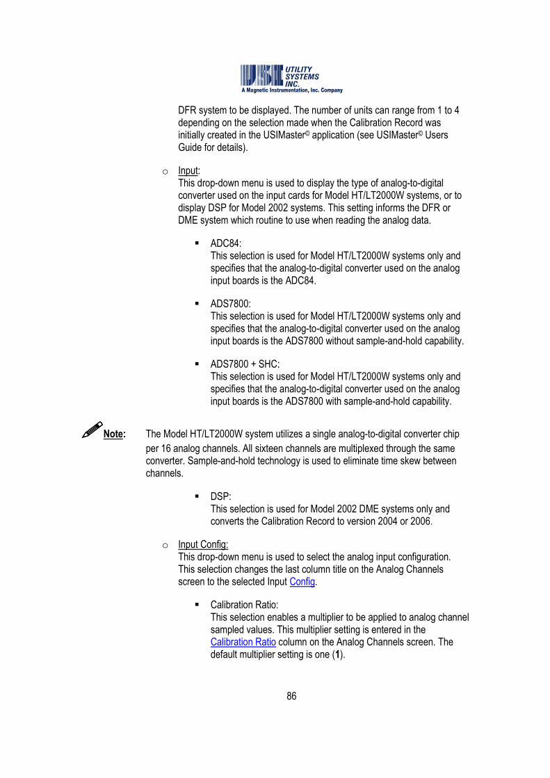
86
DFR system to be displayed. The number of units can range from 1 to 4 depending on the selection made when the Calibration Record was initially created in the USIMaster© application (see USIMaster© Users Guide for details).
o Input: This drop-down menu is used to display the type of analog-to-digital converter used on the input cards for Model HT/LT2000W systems, or to display DSP for Model 2002 systems. This setting informs the DFR or DME system which routine to use when reading the analog data.
� ADC84: This selection is used for Model HT/LT2000W systems only and specifies that the analog-to-digital converter used on the analog input boards is the ADC84.
� ADS7800: This selection is used for Model HT/LT2000W systems only and specifies that the analog-to-digital converter used on the analog input boards is the ADS7800 without sample-and-hold capability.
� ADS7800 + SHC: This selection is used for Model HT/LT2000W systems only and specifies that the analog-to-digital converter used on the analog input boards is the ADS7800 with sample-and-hold capability.
����Note: The Model HT/LT2000W system utilizes a single analog-to-digital converter chip
per 16 analog channels. All sixteen channels are multiplexed through the same converter. Sample-and-hold technology is used to eliminate time skew between channels.
� DSP: This selection is used for Model 2002 DME systems only and converts the Calibration Record to version 2004 or 2006.
o Input Config: This drop-down menu is used to select the analog input configuration. This selection changes the last column title on the Analog Channels screen to the selected Input Config.
� Calibration Ratio: This selection enables a multiplier to be applied to analog channel sampled values. This multiplier setting is entered in the Calibration Ratio column on the Analog Channels screen. The default multiplier setting is one (1).

87
� Ext. Shunt (mOhm): This selection is used to indicate that the current-measuring analog inputs are receiving signals from an external shunt or auxiliary CT device as apposed to the system internal shunt. The actual value of the external shunt or the equivalent shunt value of the auxiliary CT device may be entered in mOhms (milliohms) into the Ext. Shunt (mOhm) column on the Analog Channels screen tab.
o Line Freq: This drop-down menu is used to select the power system frequency being monitored. This setting is used to define the cycle period and number of data samples used by the trigger algorithms.
o Frequency: These drop-down menus are used to select the TRANSIENT and LONGTERM sampling frequencies (samples per second) at which the DME system analog-to-digital converters operate.
� TRANSIENT: Sample rate selections available are displayed in this drop-down menu. These sampling frequencies are valid for all Model 2002 systems and are not dependent on the number of analog inputs. All analog and digital inputs are sampled at the selected rate.
� LONGTERM: Sample rate selections available are displayed in this drop-down menu. These sampling frequencies are valid for all Model 2002 systems and are not dependent on the number of analog inputs.
����Note: Sample rate selection of 0Hz disables Long Term recording.
o Pre-Fault: This setting determines the period of prefault data that the DME system will record prior to the actual trigger event. This value is set for both the Transient and Long Term recorders. Transient record Pre-Fault can be set to a maximum of ten (10) seconds. Long term Pre-Fault can be set to a maximum of 990 seconds.
o Post-Fault: This setting determines the period of Post-Fault data that the DME system will record after the triggers and events clear, or after the Fault Limit period has expired. This value is set for both the Transient and Long Term recorders. Transient Post-Fault can be set to a maximum of ten (10) seconds. Long Term Post-Fault can be set to a maximum of 990 seconds.
88
o Fault Limit: This setting determines the time limit of any record. This value is set for both Transient and Long-Term recorders. Transient Fault Limit may be set for a maximum of ten (10) seconds. Long term Fault Limit is not applicable.
����Note: The total length of a fault record is equal to (Pre-Fault period) + (Fault period) +
Post-Fault period). If an analog or digital trigger should re-occur during the Post-Fault period, the fault record will be extended to contain the entire event in a single COMTRADE data file. The maximum length of a Fault Record in a re-trigger situation is 40 seconds.
• DSP Boards Config (Version 2004) The DSP Boards Config screen tab is used to assign the following settings (Figure 2-77):
Figure 2-77 DSP Boards Configuration Screen Tab – Version 2004
Caution: Do not change the factory settings for #DSP or DSP Configuration except as directed by USI personnel. These settings must match the physical configuration of the chassis for the system to function correctly.
o Total DSPs: This drop-down menu is used to select the number of DSP boards present in the selected unit. The possible number of boards per unit ranges from one to 16. A row is added to the DSP Configuration table for each DSP

89
board. Each board is assigned an identification address (DSP ID) sequentially from ID0 to ID15. This DSP ID number is also assigned on the DSP board by shorting jumpers.
o DSP Configuration: This drop-down list is used to select the configuration of each DSP board in the selected unit. To modify the configuration of a DSP board, select the corresponding row in the table and choose a new configuration from the drop-down list. Possible selections are as follows:
� a(8A+32D) This selection configures the selected DSP board to process eight analog channels and 32 digital inputs.
� b(8A+0D) This selection configures the selected DSP board to process eight analog channels and zero digital inputs.
� c(0A+32D) This selection configures the selected DSP board to process zero analog channels and 32 digital inputs.
� d(0A+64D) This selection configures the selected DSP board to process zero analog channels and 64 digital inputs.
� e(0A+96D) This selection configures the selected DSP board to process zero analog channels and 96 digital inputs.
� f(0A+128D) This selection configures the selected DSP board to process zero analog channels and 128 digital inputs.
� g(0A+160D) This selection configures the selected DSP board to process zero analog channels and 160 digital inputs.
����Note: DSP configuration g(0A-160D) requires a custom 6U chassis to accommodate this
number of digital inputs in a single chassis.
o Com Bd: This column identifies which DSP boards have had a Common board installed. This extra board, a type of daughterboard, provides system timing signals. At least one DSP board in each system must have a Common board attached. Multiple Common boards are used in distributed systems where portions of a single unit
90
are located greater than 150 feet apart. The presence of a Common board on a DSP is indicated by an x in the DSP ID row. To indicate the presence of a Common board on a DSP, select the row in the DSP configuration table and select the checkbox above the Com Bd column.
o Event Debounce (ms): This field is used to enter the period of time that the system provides digital filtering to digital inputs. The default setting is four (4) milliseconds. This filter is applied to help prevent the recording of contact bounces. This filter is applied to the trigger function of digital inputs. It is also applied to digital inputs designated as SER inputs and as DFR inputs configured to trigger the DME system. Once a state change is detected on a digital input, the timestamp of the initial state change is recorded and the trigger function is halted for the Event Debounce period. A comparison is then made between the initial state change and the state of the input after this period. If the states are the same, the Event Trigger is validated and recording is initiated. The Event Debounce time does not delay the start of fault recording. A Fault Record start time will still reflect the first detection of a change of state provided the debounced event remains steady state for the debounce time.
����Note: Use caution when setting the Event Debounce period. Setting too long a period
can result in missed event triggers and setting too short a period can result in contact bounces being recorded as SER data.
o A SER Channel Auto Stop From Scan If: These settings define when a digital input (event) is temporarily inhibited from triggering an SER recording. There are two fields that define the inhibit start time and one field that defines the inhibit stop time.
� #Events This field indicates the number of state changes (#Events) that must occur within the specified time period before an Auto Stop occurs.
� happened in #Minutes This field indicates the time period within which the specified number of events (#Events) must occur to cause an Auto Stop.
� Then Auto Restore after #Minutes This field indicates the period of time (#Minutes) the trigger function of the offending digital input will be disabled. At the end of this period the triggering is automatically re-enabled.

91
• Installed Hardware Options This checkbox indicates that the analog input channels have a 10kHz low pass input filter. This setting is relevant only when the PMU option is enabled on the DME system.
• Analog Channels (Version 2004) The Analog Channels section is used to assign the following settings (Figure 2-78).
Figure 2-78 Analog Channels Tab – Version 2004
o IN#: This column displays the analog channel number for each physical input.
o Analog Channel Description: This column displays the alpha-numeric description entered for each analog input. The analog channel description is limited to 80 characters.
o Type: This column displays the channel type selected for each analog input:
� v(Vac) This selection indicates that the analog input is monitoring an AC voltage signal.
� v(Vac) This selection indicates that the analog input is monitoring an AC voltage signal.
� V(Vdc) This selection indicates that the analog input is monitoring a DC voltage signal.

92
� c(Aac-Reg) This selection indicates that the analog input is monitoring an AC current signal measured by an internal current shunt. This input type connects to the HT/LT2000W system between the I and C terminals.
� c(Aac-Shunt) This selection indicates that the analog input is monitoring an AC current signal by measuring the voltage output of an external current shunt or an auxiliary current transformer device.
� C(Adc-Reg) This selection indicates that the analog input is monitoring a DC current signal measured by an internal current shunt. This input type connects to the HT/LT2000W system between the I and C terminals.
� C(Adc-Shunt) This selection indicates that the analog input is monitoring a DC current signal by measuring the voltage output of a current shunt or an external current transformer device.
� f(Hz) This selection indicates that the analog input is monitoring frequency by measuring the DC voltage output of a transducer external to the system.
� w(MWatt) This selection indicates that the analog input is monitoring megawatts by measuring the DC voltage output of a transducer external to the system.
� q(MVar) This selection indicates that the analog input is monitoring megaVARs by measuring the DC voltage output of a transducer external to the system.
Caution: If +/-/0 sequence triggers, single-phase W/VAR/PF triggers, or three-phase W/VAR/PF triggers are planned to be used, see Figure 2-79 for channel assignment recommendations.
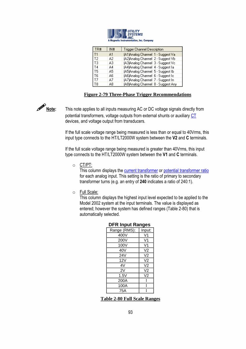
93
Figure 2-79 Three-Phase Trigger Recommendations
����Note: This note applies to all inputs measuring AC or DC voltage signals directly from
potential transformers, voltage outputs from external shunts or auxiliary CT devices, and voltage output from transducers. If the full scale voltage range being measured is less than or equal to 40Vrms, this input type connects to the HT/LT2000W system between the V2 and C terminals. If the full scale voltage range being measured is greater than 40Vrms, this input type connects to the HT/LT2000W system between the V1 and C terminals.
o CT/PT: This column displays the current transformer or potential transformer ratio for each analog input. This setting is the ratio of primary to secondary transformer turns (e.g. an entry of 240 indicates a ratio of 240:1).
o Full Scale: This column displays the highest input level expected to be applied to the Model 2002 system at the input terminals. The value is displayed as entered; however the system has defined ranges (Table 2-80) that is automatically selected.
DFR Input Ranges Range (RMS): Input:
400V V1 200V V1 100V V1 40V V2 24V V2 12V V2 4V V2 2V V2
1.5V V2 200A I 100A I 75A I
Table 2-80 Full Scale Ranges
94
����Note: Care should be taken when selecting full scale levels. Setting these values too low
will result in clipping when the input signal exceeds the preset level; conversely; setting these values too high will result in reduced accuracy of low level readings.
����Note: For analog channels measuring voltages from external shunts or auxiliary CT
devices [e.g. c(Aac-Shunt) or C(Adc-Shunt)] the full scale value entered must be as seen at the external current sensing device. The software will automatically calculate the proper full scale voltage range based on the current full scale and the external shunt resistance values. This value is calculated as: E(range) = I(full scale) * R(ext. shunt).
����Note: After changing full scale ranges on a Model 2002 system, run the Internal
Calibration to ensure accuracy within 0.25% of reading.
o Calibration Ratio / Ext. Shunt (mOhm): This column title is determined by the setting previously made from the Input Configuration drop-down list on the station header.
� Calibration Ratio This column displays any additional multiplier to be applied to the measured data during analysis. Primary values for analog channels are calculated as follows: [measured input value] x [CAL Ratio] x [CT/PT Ratio]. The default setting for this column is one (1).
� Ext. Shunt (mOhm) This column displays the value in milliohms, of the external shunt resistor or the equivalent shunt value of an auxiliary current transformer device. The system uses these stored resistance values to convert sensed voltages to their equivalent line currents (R = E ÷ I ).
• Trigger Channels (Version 2004) The Trigger Channels section is used to assign the following settings (Figure 2-81).

95
Figure 2-81 Trigger Channels Tab
o TR#: This column displays the analog trigger numbers available to be assigned to an analog channel.
o IN#: This column displays the analog channel number assigned to an analog trigger. In calibration record V2004 only 8 triggers can be assigned to each group of 8 analog channels (e.g. 1-8, 9-16, 17-24, etc.).
o Trigger Channels Description: This column displays the alpha-numeric description entered for each trigger channel. The trigger channel description is limited to 80 characters. This descriptor will display in the Events/Triggers Tripped column of the Quick Summary and History Data screens. This descriptor can be exactly the same as the Analog Channel description or it can be tailored to identify the analog trigger more specifically (e.g. adding harmonic, frequency, etc. to identify specifically the unit that this trigger is monitoring).
����Note: A Trigger Channel Description displays only on the Quick Summary and History
Data tabs. Therefore, it may be desirable to add the trigger type to the trigger name.
o Type:
This column displays the trigger type that is applied to each analog input.
� Disable This selection prevents the selected trigger from initiating a recording.
96
� RMS This selection enables an analog channel to initiate a recording based on the RMS level of the analog signal.
� Hertz This selection enables an analog channel to initiate a recording based on the frequency of the analog signal.
� Zero Seq This selection enables a group of three-phase analog channels to initiate a recording based on the zero sequence value.
� Pos Seq This selection enables a group of three-phase analog channels to initiate a recording based on the positive sequence value.
� Neg Seq This selection enables a group of three-phase analog channels to initiate a recording based on the negative sequence value.
����Note: Sequence trigger types must be assigned to the analog channel monitoring Phase-
A of the three-phase group. The system assumes that the following two analog channels are Phase-B and Phase-C, respectively. All three-phase inputs must be in the same group of eight analog channels and must be the same analog channel type.
� Harmonic This selection enables an analog channel to initiate a recording based on the harmonic level of the analog signal. This trigger type calculates the first through the eighth harmonic and triggers the system if any single harmonic exceeds the Trip if Over setting.
� THD This selection enables an analog channel to initiate a recording based on the harmonic level of the analog signal. This trigger type calculates the first through the eighth harmonic and triggers the system if the sum of the first eight harmonics exceeds the Trip if Over setting.
� 1 ph. W This selection enables a single-phase group of analog channels to initiate a recording based on the real power level.

97
� 1 ph. Vr This selection enables a single-phase group of analog channels to initiate a recording based on the reactive power level (VAR).
� 1 ph. PF This selection enables a single-phase group of analog channels to initiate a recording based on the power factor level.
����Note: Single-phase trigger types are calculated from analog channels measuring one
voltage phase and one current phase. The system assumes that the following third analog channel is the current phase. The single-phase trigger must be assigned to the analog channel monitoring the voltage phase. Both phase inputs must be in the same group of eight (8) analog channels.
� 3 ph. W This selection enables a three-phase group of analog channels to initiate a recording based on the real power level.
� 3 ph. Vr This selection enables a three-phase group of analog channels to initiate a recording based on the reactive power level (VAR).
� 3 ph. PF This selection enables a three-phase group of analog channels to initiate a recording based on the power factor level.
����Note: Three-Phase trigger types are calculated from analog channels measuring three
voltage phases and three current phases. The system assumes that the analog inputs are connected in the order shown in Table 2-82, below. The three-phase trigger must be assigned to the analog channel monitoring the A-phase voltage input. All six phase inputs must be in the same group of eight analog channels; therefore, three-phase trigger types can only be assigned to the first or second input in each group of eight channels.
Table 2-82 Three-Phase Trigger Restrictions

98
o Start: This drop-down list is used to choose a start condition. Start choices are shown below:
� o(Over) The selected trigger will start if an overvoltage limit is exceeded.
� u(Under) The selected trigger will start if an undervoltage limit is exceeded.
� b(Both) The selected trigger will start if either an overvoltage limit or an undervoltage limit is exceeded.
o Duration: This field displays the time period which a trigger must remain continuously abnormal before it will initiate a recording. The default setting is zero (0.000) seconds which initiates a recording instantly. This setting is applicable to all trigger types but is most often used in conjunction with a rate-of-change setting for disturbance type triggers.
o Trip if Over: This field displays the level at which an over trigger will initiate a recording.
o Trip if Under: This field displays the level at which an under trigger will initiate a recording.
o Trip if Rate > x/s: This field is used to enable a rate-of-change trigger. The trigger starts the fault recording process when the measured value exceeds this set limit. The default value is zero (0) which disables rate-of-change triggering.
Example: Analog channel type is Vac The trigger type is RMS The Trip if Rate >?/s is 1.000 Recording will begin if the RMS voltage rate-of-change exceeds one Volt per second.
����Note: The rate-of-change trigger does not have to exceed the limit for an entire second.
The Duration setting defines the time period in milliseconds over which the rate of change must occur before a recording is triggered. This period can be as short as one (1) millisecond.
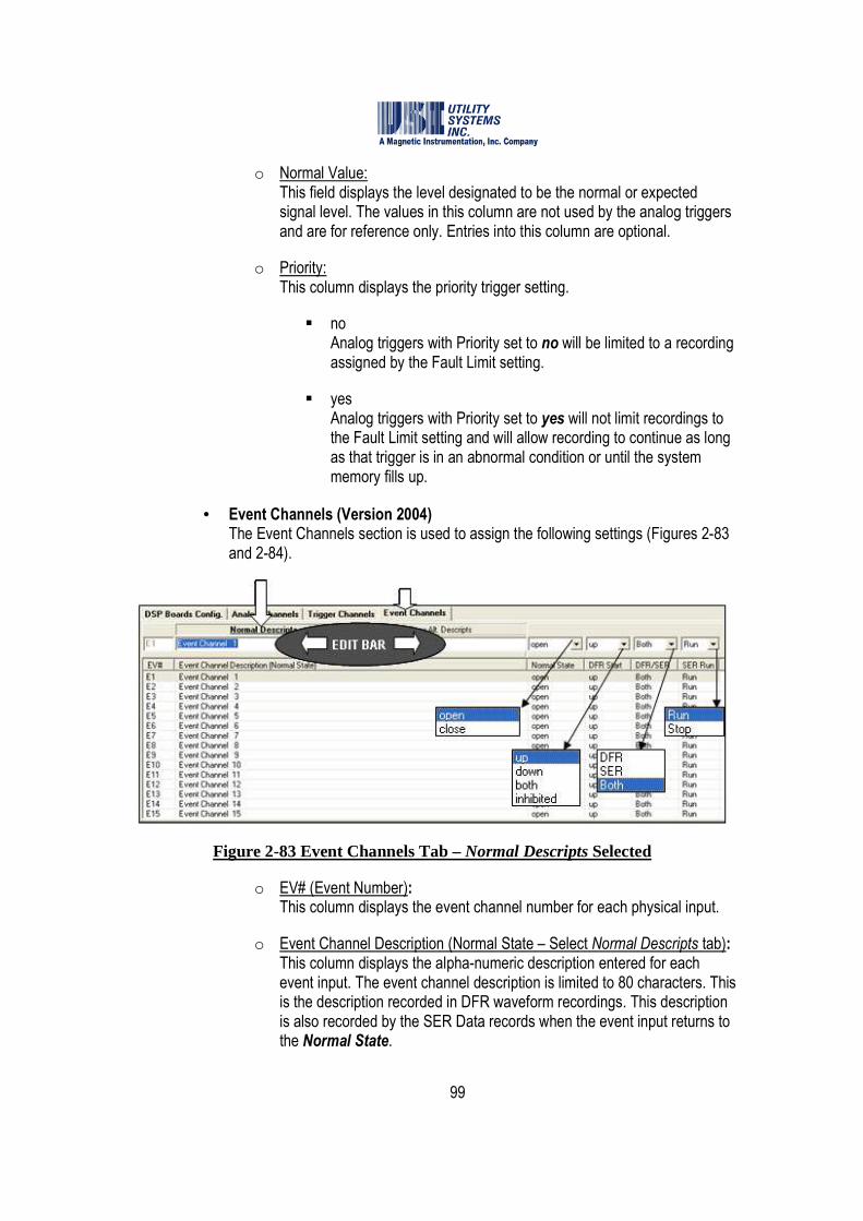
99
o Normal Value: This field displays the level designated to be the normal or expected signal level. The values in this column are not used by the analog triggers and are for reference only. Entries into this column are optional.
o Priority: This column displays the priority trigger setting.
� no Analog triggers with Priority set to no will be limited to a recording assigned by the Fault Limit setting.
� yes Analog triggers with Priority set to yes will not limit recordings to the Fault Limit setting and will allow recording to continue as long as that trigger is in an abnormal condition or until the system memory fills up.
• Event Channels (Version 2004) The Event Channels section is used to assign the following settings (Figures 2-83 and 2-84).
Figure 2-83 Event Channels Tab – Normal Descripts Selected
o EV# (Event Number): This column displays the event channel number for each physical input.
o Event Channel Description (Normal State – Select Normal Descripts tab): This column displays the alpha-numeric description entered for each event input. The event channel description is limited to 80 characters. This is the description recorded in DFR waveform recordings. This description is also recorded by the SER Data records when the event input returns to the Normal State.
100
o Normal State: This setting defines the normal state of an event input.
� open This selection indicates that a logic zero (0) detected by the recorder is to be considered the normal state and a logic one (1) detected by the recorder is to be considered the abnormal state.
� close This selection indicates that a logic zero (0) detected by the recorder is to be considered the abnormal state and a logic one (1) detected by the recorder is to be considered the normal state.
o DFR Start: This setting determines whether an event input will trigger the recording process producing a COMTRADE data file.
� up This selection enables the selected event input to trigger a DFR waveform recording on a transition from a logic zero (0) to a logic one (1) condition (e.g. the closing of the monitored event input contact).
� down This selection enables the selected event input to trigger a DFR waveform recording on a transition from a logic one (1) to a logic zero (0) condition (e.g. the opening of the monitored event input contact).
� both This selection enables the selected event input to trigger a DFR waveform recording on either the transition from a logic zero (0) to a logic One (1) condition (e.g. the closing of the monitored event input contact) or the transition from a logic one (1) to a logic zero (0) condition (e.g. the opening of the monitored event input contact).
� Inhibit This selection prevents the selected event input from triggering a DFR waveform recording. The status of the event input is still monitored and recorded when the DME system is triggered by an analog trigger or another event input but an inhibited input alone cannot trigger a DFR waveform recording.
o DFR/SER: This setting determines how the selected event input is to be recorded.
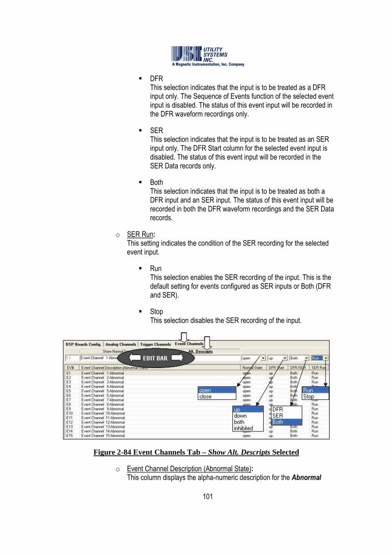
101
� DFR This selection indicates that the input is to be treated as a DFR input only. The Sequence of Events function of the selected event input is disabled. The status of this event input will be recorded in the DFR waveform recordings only.
� SER This selection indicates that the input is to be treated as an SER input only. The DFR Start column for the selected event input is disabled. The status of this event input will be recorded in the SER Data records only.
� Both This selection indicates that the input is to be treated as both a DFR input and an SER input. The status of this event input will be recorded in both the DFR waveform recordings and the SER Data records.
o SER Run: This setting indicates the condition of the SER recording for the selected event input.
� Run This selection enables the SER recording of the input. This is the default setting for events configured as SER inputs or Both (DFR and SER).
� Stop This selection disables the SER recording of the input.
Figure 2-84 Event Channels Tab – Show Alt. Descripts Selected
o Event Channel Description (Abnormal State): This column displays the alpha-numeric description for the Abnormal
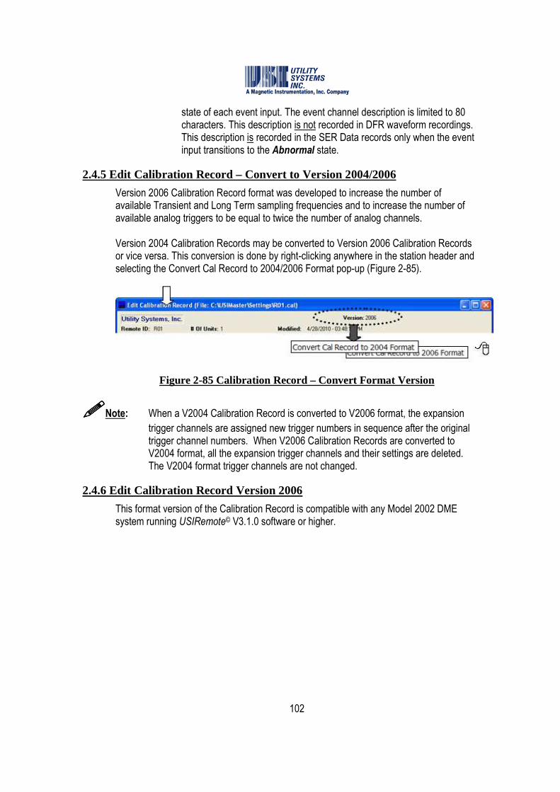
102
state of each event input. The event channel description is limited to 80 characters. This description is not recorded in DFR waveform recordings. This description is recorded in the SER Data records only when the event input transitions to the Abnormal state.
2.4.5 Edit Calibration Record – Convert to Version 2004/2006
Version 2006 Calibration Record format was developed to increase the number of available Transient and Long Term sampling frequencies and to increase the number of available analog triggers to be equal to twice the number of analog channels. Version 2004 Calibration Records may be converted to Version 2006 Calibration Records or vice versa. This conversion is done by right-clicking anywhere in the station header and selecting the Convert Cal Record to 2004/2006 Format pop-up (Figure 2-85).
Figure 2-85 Calibration Record – Convert Format Version
����Note: When a V2004 Calibration Record is converted to V2006 format, the expansion
trigger channels are assigned new trigger numbers in sequence after the original trigger channel numbers. When V2006 Calibration Records are converted to V2004 format, all the expansion trigger channels and their settings are deleted. The V2004 format trigger channels are not changed.
2.4.6 Edit Calibration Record Version 2006
This format version of the Calibration Record is compatible with any Model 2002 DME system running USIRemote© V3.1.0 software or higher.
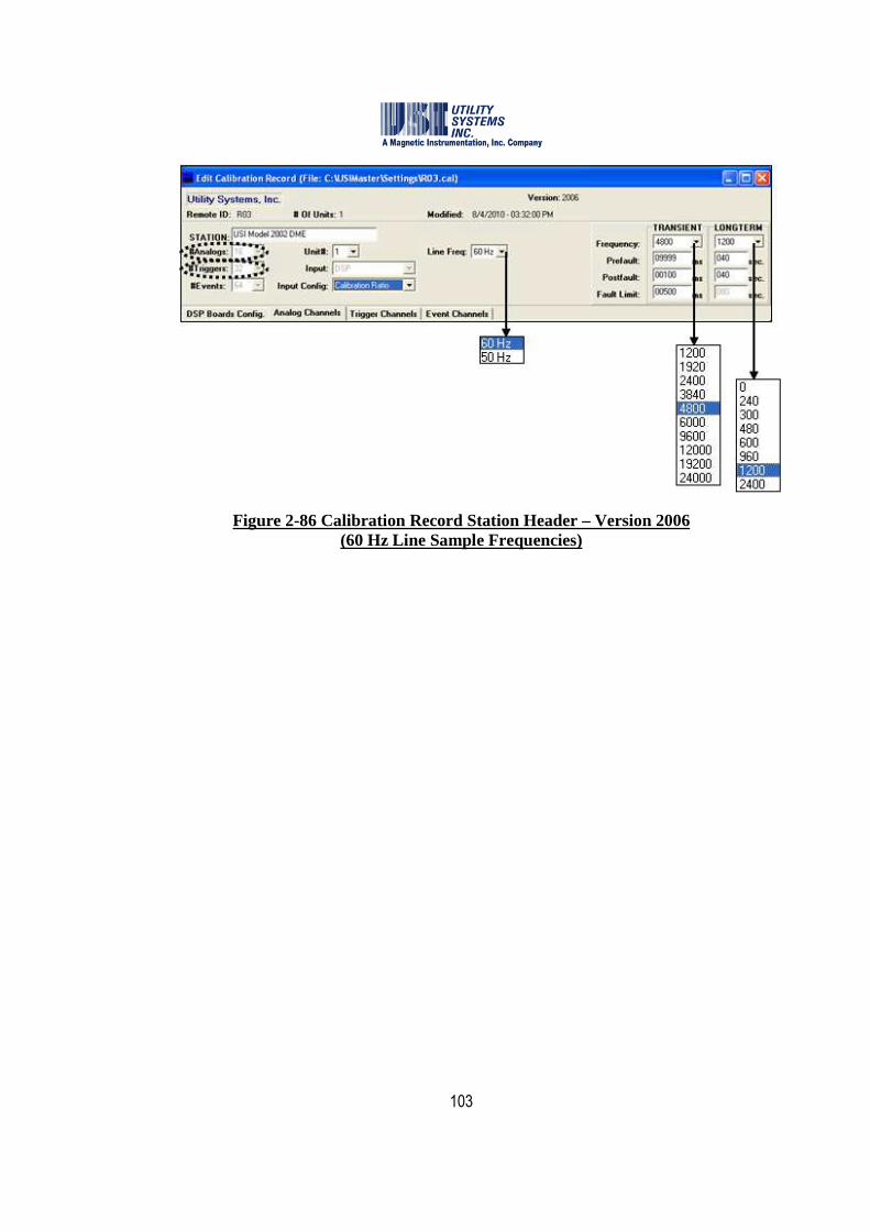
103
Figure 2-86 Calibration Record Station Header – Version 2006 (60 Hz Line Sample Frequencies)

104
Figure 2-87 Calibration Record Station Header - Version 2006 (50 Hz Line Sample Frequencies)
• Station Header (Version 2006) The Station Header section is used to assign the following settings (Figures 2-86 and 2-87). All settings in the V2006 station header are the same as the V2004 station header except for the following:
o #Triggers: This field displays the total number of available analog triggers for the selected Unit of the DME system. In Calibration Record Version 2006, the number of available analog triggers is equal to twice the number of available analog channels.
o Frequency: These drop-down menus are used to select the TRANSIENT and LONGTERM sampling frequencies (samples per second) at which the DME system analog-to-digital converters operate.
105
� TRANSIENT Sample rate selections available from this drop-down menu are dependent on the Line Freq: setting. These sampling frequencies are valid for all Model 2002 systems running USIRemote© V3.1.0 or later and are not dependent on the number of analog inputs. All the analog and digital inputs are sampled at the selected rate.
� LONGTERM Sample rate selections available from this drop-down menu are dependent on the Line Freq: setting. These sampling frequencies are valid for all Model 2002 systems running USIRemote© V3.1.0 or later and are not dependent on the number of analog inputs.
����Note: The LONGTERM sampling frequencies displayed will vary depending on the
selected TRANSIENT sampling frequency. The LONGTERM frequencies displayed are only those that have a common denominator with the TRANSIENT frequency and that are evenly divisible by the line frequency (e.g. 60 Hz or 50 Hz).
• Trigger Channels (Version 2006) The Trigger Channels section is used to assign the following settings (Figure 2-88). All settings in the V2006 trigger channels are the same as the V2004 format except for the following:
o TR#: This column displays the analog trigger numbers available to be assigned to an analog channel. In a V2006 format Calibration Record, the number of available analog triggers is twice the number of available analog channels.
����Note: No more than 16 analog triggers can be assigned to each group of eight analog
channels.
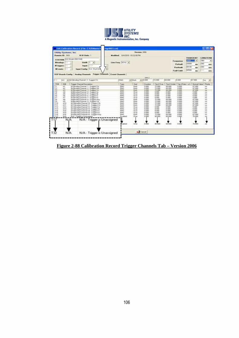
106
Figure 2-88 Calibration Record Trigger Channels Tab – Version 2006
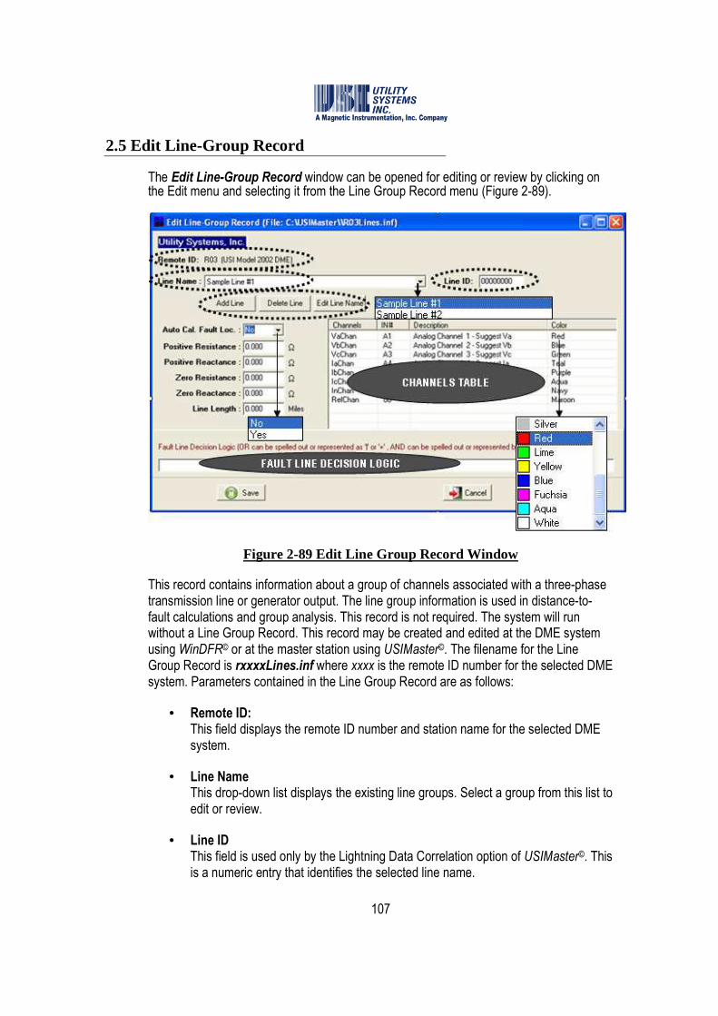
107
2.5 Edit Line-Group Record
The Edit Line-Group Record window can be opened for editing or review by clicking on the Edit menu and selecting it from the Line Group Record menu (Figure 2-89).
Figure 2-89 Edit Line Group Record Window
This record contains information about a group of channels associated with a three-phase transmission line or generator output. The line group information is used in distance-to-fault calculations and group analysis. This record is not required. The system will run without a Line Group Record. This record may be created and edited at the DME system using WinDFR© or at the master station using USIMaster©. The filename for the Line Group Record is rxxxxLines.inf where xxxx is the remote ID number for the selected DME system. Parameters contained in the Line Group Record are as follows:
• Remote ID: This field displays the remote ID number and station name for the selected DME system.
• Line Name This drop-down list displays the existing line groups. Select a group from this list to edit or review.
• Line ID This field is used only by the Lightning Data Correlation option of USIMaster©. This is a numeric entry that identifies the selected line name.
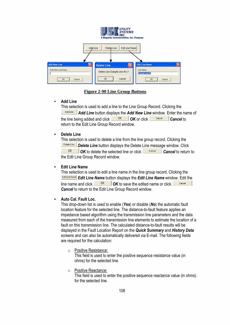
108
Figure 2-90 Line Group Buttons
• Add Line This selection is used to add a line to the Line Group Record. Clicking the
Add Line button displays the Add New Line window. Enter the name of
the line being added and click OK or click Cancel to return to the Edit Line Group Record window.
• Delete Line This selection is used to delete a line from the line group record. Clicking the
Delete Line button displays the Delete Line message window. Click
OK to delete the selected line or click Cancel to return to the Edit Line Group Record window.
• Edit Line Name This selection is used to edit a line name in the line group record. Clicking the
Edit Line Name button displays the Edit Line Name window. Edit the
line name and click OK to save the edited name or click Cancel to return to the Edit Line Group Record window.
• Auto Cal. Fault Loc. This drop-down list is used to enable (Yes) or disable (No) the automatic fault location feature for the selected line. The distance-to-fault feature applies an impedance based algorithm using the transmission line parameters and the data measured from each of the transmission line elements to estimate the location of a fault on this transmission line. The calculated distance-to-fault results will be displayed in the Fault Location Report on the Quick Summary and History Data screens and can also be automatically delivered via E-mail. The following fields are required for the calculation:
o Positive Resistance: This field is used to enter the positive sequence resistance value (in ohms) for the selected line.
o Positive Reactance: This field is used to enter the positive sequence reactance value (in ohms) for the selected line.
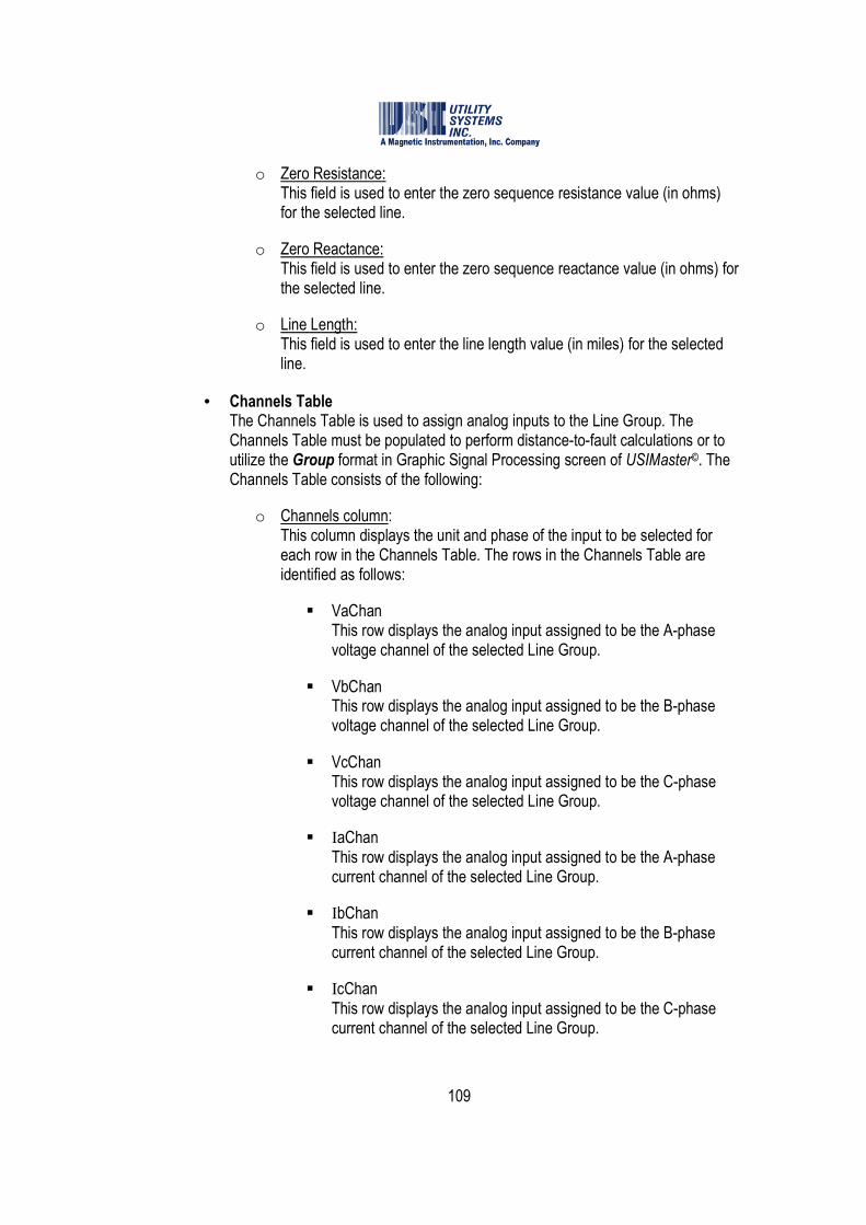
109
o Zero Resistance: This field is used to enter the zero sequence resistance value (in ohms) for the selected line.
o Zero Reactance: This field is used to enter the zero sequence reactance value (in ohms) for the selected line.
o Line Length: This field is used to enter the line length value (in miles) for the selected line.
• Channels Table The Channels Table is used to assign analog inputs to the Line Group. The Channels Table must be populated to perform distance-to-fault calculations or to utilize the Group format in Graphic Signal Processing screen of USIMaster©. The Channels Table consists of the following:
o Channels column: This column displays the unit and phase of the input to be selected for each row in the Channels Table. The rows in the Channels Table are identified as follows:
� VaChan This row displays the analog input assigned to be the A-phase voltage channel of the selected Line Group.
� VbChan This row displays the analog input assigned to be the B-phase voltage channel of the selected Line Group.
� VcChan This row displays the analog input assigned to be the C-phase voltage channel of the selected Line Group.
� IaChan This row displays the analog input assigned to be the A-phase current channel of the selected Line Group.
� IbChan This row displays the analog input assigned to be the B-phase current channel of the selected Line Group.
� IcChan This row displays the analog input assigned to be the C-phase current channel of the selected Line Group.

110
� InChan This row displays the analog input assigned to be the Neutral current channel of the selected Line Group.
� RefChan This row displays the analog input assigned to be used as reference for the selected Line Group. Configuring this row is optional and this channel is only displayed in the USIMaster© - Graphic Signal Processing window.
o IN#: This column displays the input number of the analog channel assigned to each row.
o Description: This column displays the descriptor for the analog channel selected for each row. The description is displayed exactly as it was entered into the Analog Channels screen of the Calibration Record.
o Color: This column displays the color to be used when this waveform is plotted in Group format of the Graphic Signal Processing window. Clicking on a color drops down a menu for choosing a different color (Figure 2-91).
Figure 2-91 Color Menu
o Channels Table Right-click menu: Right-clicking on any row in the Channels Table will display the following menu (Figure 2-92):
Figure 2-92 Channels Table - Right-click Menu
� Select Analog Channel This selection displays the Select Analog Channel for XxChan window. This window displays the list of analog channels by input number and description to choose for the selected row (e.g. Va,
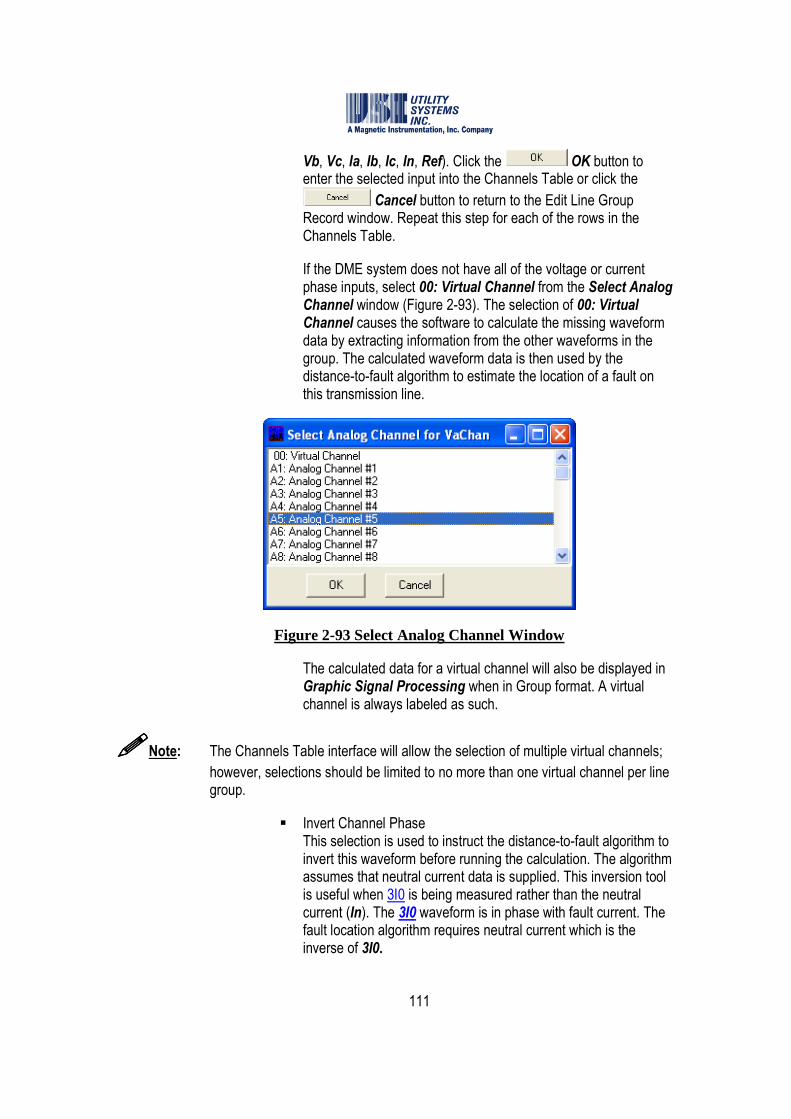
111
Vb, Vc, Ia, Ib, Ic, In, Ref). Click the OK button to enter the selected input into the Channels Table or click the
Cancel button to return to the Edit Line Group Record window. Repeat this step for each of the rows in the Channels Table.
If the DME system does not have all of the voltage or current phase inputs, select 00: Virtual Channel from the Select Analog Channel window (Figure 2-93). The selection of 00: Virtual Channel causes the software to calculate the missing waveform data by extracting information from the other waveforms in the group. The calculated waveform data is then used by the distance-to-fault algorithm to estimate the location of a fault on this transmission line.
Figure 2-93 Select Analog Channel Window
The calculated data for a virtual channel will also be displayed in Graphic Signal Processing when in Group format. A virtual channel is always labeled as such.
����Note: The Channels Table interface will allow the selection of multiple virtual channels;
however, selections should be limited to no more than one virtual channel per line group.
� Invert Channel Phase This selection is used to instruct the distance-to-fault algorithm to invert this waveform before running the calculation. The algorithm assumes that neutral current data is supplied. This inversion tool is useful when 3I0 is being measured rather than the neutral current (In). The 3I0 waveform is in phase with fault current. The fault location algorithm requires neutral current which is the inverse of 3I0.
112
• Fault Line Decision Logic This logic (see Table 2-94 and following examples) is a Boolean equation of analog triggers and digital events and determines whether a fault calculation should be carried out, based on which triggers and events were abnormal during each DFR record. This field is used by the distance-to-fault algorithm to determine which line from the Line Group Record tripped due to a fault. If field is left empty, the distance-to-fault will run only on the first line group it checks because a blank Fault Line Decision Logic is interpreted as True. Line group logic statements are limited to 200 characters. Spaces are legal characters and are ignored, but they count towards the 200 character limit.
����Note: The distance-to-fault algorithm calculated fault location only on a single line group
for each fault record.
Boolean Operators Logic Description & , *, AND AND function
|, +, OR OR function
t1, t2, t3, etc Triggers
e1, e2, e3, etc Events
0 (zero) False, will never pass logic filter
1 True, will always pass logic filter Nothing (blank) True, will always pass logic filter
Parentheses ( ) Groups logic
Spaces Spaces are ignored by the logic
Table 2-94 Fault Line Decision Logic
Examples: Below are three different syntax samples for the same equation.
(T1|T2|T3|T4|T8|T5|T6|T7) & ((E4 | E5) & E11)
(T1+T2+T3+T4+T8+T5+T6+T7) * ((E4 + E5) * E11)
(T1 OR T2 OR T3 OR T4 OR T8 OR T5 OR T6 OR T7) AND ((E4 OR E5) AND E11)
• Save This selection is used to save all setting changes made and to close the Edit Line-Group Record window. After this selection is made, the Line-Group Record is Saved message displays (Figure 2-95). Click OK to acknowledge. After acknowledging that the Line-Group Record is saved, the Send Line-Group

113
Record to Remote message window displays (Figure 2-95). Selecting Yes initiates a communication connection with the recorder, uploads the Line-Group Record, and re-initializes the system putting the new settings into effect. Selecting No will close the Send Line-Group Record to Remote window without sending the saved file to the recorder.
Figure 2-95 Save Line-Group Record
����Note: If the Save button displays a red Locked symbol, the global Administrator
privileges are disabled (Figure 2-16). Click the locked Save button and the Administrator Password window is displayed (Figure 2-96). Enter a valid
Administrator password entry and click OK to Save.
Figure 2-96 Administrator Password Window
• Cancel This selection is used to cancel all setting changes made and to close the Edit Line-Group Record window.
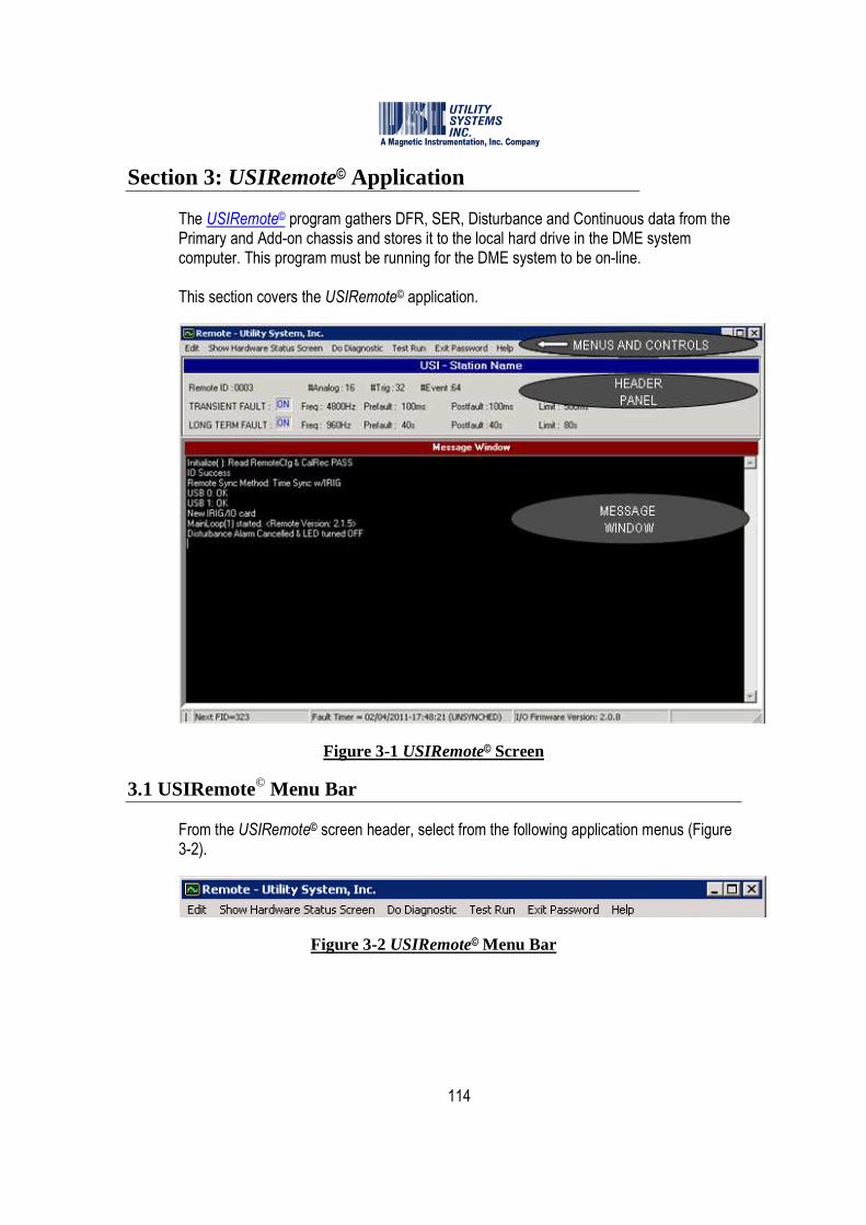
114
Section 3: USIRemote© Application
The USIRemote© program gathers DFR, SER, Disturbance and Continuous data from the Primary and Add-on chassis and stores it to the local hard drive in the DME system computer. This program must be running for the DME system to be on-line. This section covers the USIRemote© application.
Figure 3-1 USIRemote© Screen
3.1 USIRemote© Menu Bar
From the USIRemote© screen header, select from the following application menus (Figure 3-2).
Figure 3-2 USIRemote© Menu Bar

115
3.1.1 USIRemote© Edit Menu
This menu provides the following selections:
Figure 3-3 USIRemote© Menu Bar
• Edit Remote Config. This selection displays the USIRemote System Configuration window (Figure 3-4). It is used to view or edit the configuration of the USIRemote application.
Figure 3-4 Remote System Configuration Window
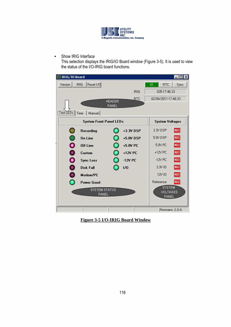
116
• Show IRIG Interface This selection displays the IRIG/IO Board window (Figure 3-5). It is used to view the status of the I/O-IRIG board functions.
Figure 3-5 I/O-IRIG Board Window
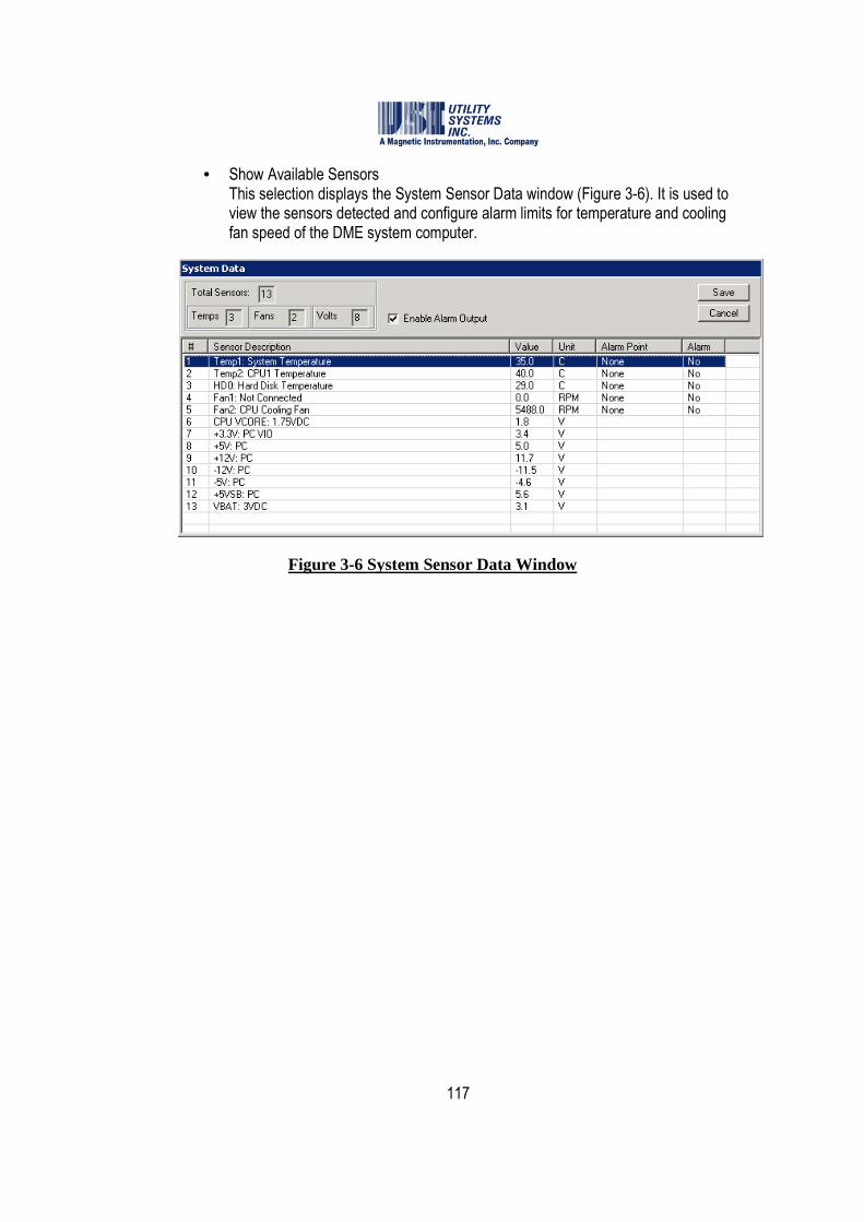
117
• Show Available Sensors This selection displays the System Sensor Data window (Figure 3-6). It is used to view the sensors detected and configure alarm limits for temperature and cooling fan speed of the DME system computer.
Figure 3-6 System Sensor Data Window

118
3.1.2 USIRemote© Show Hardware Status Screen Menu
This selection displays the USB-DSP Board Communication Status window (Figure 3-7). This window has a message window to show information related to system timing, firmware version, and communication details between the DME system computer and the DSP boards.
The table below the message window displays communication details of each specific DSP boards. This information is useful it troubleshooting. Otherwise this window can be closed.
Figure 3-7 USIRemote© Menu Bar
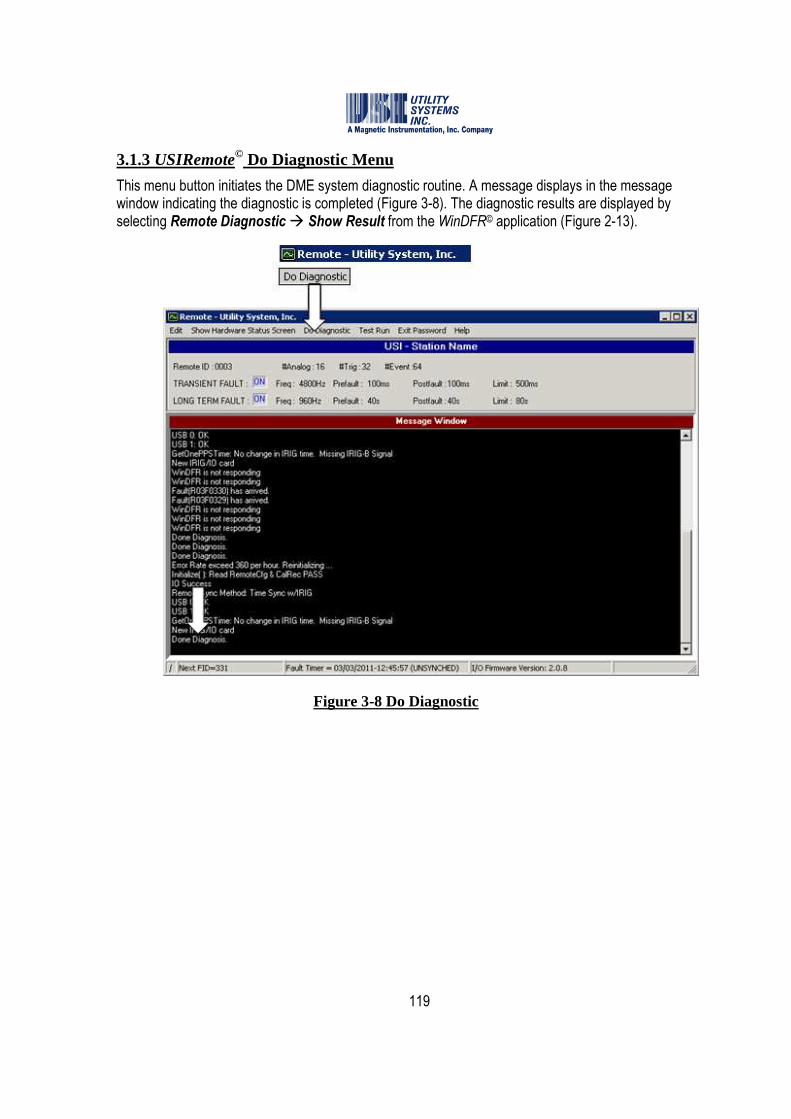
119
3.1.3 USIRemote© Do Diagnostic Menu
This menu button initiates the DME system diagnostic routine. A message displays in the message window indicating the diagnostic is completed (Figure 3-8). The diagnostic results are displayed by selecting Remote Diagnostic � Show Result from the WinDFR© application (Figure 2-13).
Figure 3-8 Do Diagnostic

120
3.1.4 USIRemote© Test Run Menu
This menu button initiates the DME system Test Run routine. A message displays in the message window indicating the Test Run is completed (Figure 3-9). This routine produces a DME record which can be viewed using the USIMaster© application (see the USIMaster© User Guide for details).
Figure 3-9 Test Run

121
3.1.5 USIRemote© Exit Password Menu
This menu button displays the Change Exit Password window (Figure 3-10). An entry in this window generates an administrator password for the USIRemote application. This password is then required to close the program which results in taking the DME system off-line.
Figure 3-10 Change Exit Password

122
3.1.6 USIRemote© Help Menu
This menu provides the following selections (Figure 3-11):
Figure 3-11 Help Menu
• Available Memory This selection displays the unused amount of physical memory on the DME system computer (Figure 3-12):
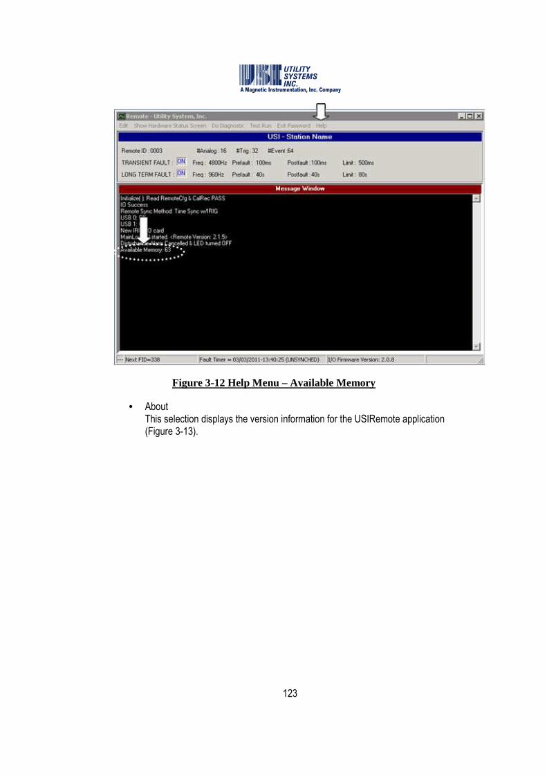
123
Figure 3-12 Help Menu – Available Memory
• About This selection displays the version information for the USIRemote application (Figure 3-13).
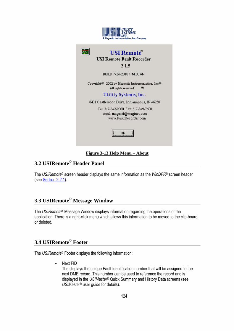
124
Figure 3-13 Help Menu – About
3.2 USIRemote© Header Panel
The USIRemote© screen header displays the same information as the WinDFR© screen header (see Section 2.2.1).
3.3 USIRemote© Message Window
The USIRemote© Message Window displays information regarding the operations of the application. There is a right-click menu which allows this information to be moved to the clip-board or deleted.
3.4 USIRemote© Footer
The USIRemote© Footer displays the following information:
• Next FID The displays the unique Fault Identification number that will be assigned to the next DME record. This number can be used to reference the record and is displayed in the USIMaster© Quick Summary and History Data screens (see USIMaster© user guide for details).

125
• Fault Timer This displays the incrementing clock time which will be assigned to future DME records and indicates if this clock is synchronized or unsynchronized to an IRIG time clock.
• I/O Firmware Version This displays the version of the firmware running on the I/O-IRIG board. Updates to this firmware are infrequent but are displayed here for convenience.

126
Section 4: Scope© Application
The Scope© program is used to perform system calibration and verification of analog and digital inputs. To run this application the USIRemote application must be closed which means the DME system is OFF-LINE. This application must be closed and the USIRemote application must be re-opened to return the DME system back ON-LINE. This section covers the Scope© application.
Figure 4-1 Scope© Screen
4.1 Scope© Menu Bar
The menus of the Scope application are the same as the USIRemote application (see Section 3).
4.2 Scope© Waveform Display Panel
This panel displays the sample data for the selected analog inputs. The description of the input displayed is shown above the waveform. The controls for this panel are located in the Meters Column to the right of the window.
127
4.3 Scope© Meter Column
This column displays the meter value for the selected analog input and also provides the following controls:
• Primary/Secondary This drop-down list determines the value displayed in the RMS meter window. If Secondary is selected the meter displays the same value that is input to the back of the DME system. When Primary is selected the value measured is multiplied by the CT/PT ratio saved in the calibration record (see Section 2.4).
• RMS This window displays the RMS value calculated for the selected analog input.
• Offset This window displays the D/C value calculated for the selected analog input.
• Y-Scale This drop-down list determines the scale of the waveform display panel. Selecting Constant results in the Y-scale set to peak value of the selected channel based on the Full Scale value entered into the calibration record (see Section 2.4). Selecting Optimized results in the Y-scale automatically scaling the applied waveform to full deflection of the waveform panel.
• Display #Cycles This field indicates the number of 60Hz cycles to display on the waveform panel.
• Analog Channel# This drop-down list is used to select the analog input number to be displayed in the waveform panel. A numeric value can be entered into the field or the UP/DOWN arrows can be used to increment or decrement the input number.
• Sequence Of This field indicates the number of sequencial analog input waveforms are displayed. The number one in this field displays only the analog input selected. The number three in this field displays the selected analog input and the two following sequential channals. This feature is useful for displaying three phases simultaneously to verify input polarity.
• Run Internal Calibration Button This button is used to activate the internal calibration process. This feature is used to perform a software calibration of all analog inputs. When this selection is made the analog input boards will take a measurement of an internal precision DC reference source. When the internal calibration process is completed a message is displayed in the application footer.

128
• Run External Calibration Button This button and the At Secondary field are used together. This feature is used only when inputs to the DFR are supplied by external shunts or auxiliary CTs. When the DME system is connected to direct five amp input circuits, the internal calibration process will calibrate the inputs to the published specifications.
• DSP ID This field displays the address of the DSP board providing the data displayed on the waveform and digital status panels. This number increments automatically as the inputs are selected.
• Run Button This button enables the Scope application to begin sampling and displaying real-time data on the waveform and digital status panels. Running is displayed on the application footer when this button is selected.
• Stop Button This button disables the Scope application from sampling and displaying real-time data on the waveform and digital status panels. Stop is displayed on the application footer when this button is selected.
• � Once Checkbox When this checkbox is selected the Run button will collect one frame of data and update the waveform and digital status panels once. When this is selected real-time update of the waveform and digital status panels are disabled.
4.4 Scope© Digital Input Status Panel
This panel displays the status of the digital inputs and the analog triggers for the selected DSP board.
• Trigger Status Displays This panel displays the trigger number as assigned in the calibration record for the selected DSP board. As the selected DSP ID increments, the associated triggers will update automatically. Placing the mouse pointer over the trigger number will display a pop-up window containing the trigger description. If the number is surrounded by a red background, the trigger is in a triggered state. If the number is surrounded by a green background, the trigger is in a non-triggered state. The trigger state is defined by the trigger settings in the calibration record (see Section 2.4).
• Event Status Displays This panel displays the digital input number for the selected DSP board. As the selected DSP ID increments, the associated triggers will update automatically.

129
Placing the mouse pointer over the trigger number will display a pop-up window containing the trigger description. If the digital input indicator is surrounded by a red background, the digital input is in a triggered state. If the digital input indicator is surrounded by a green background, the digital input is in a non-triggered state. The trigger state is defined by the trigger settings in the calibration record (see Section 2.4). If the digital input indicator contains “O” the field contact is open and field contact voltage is removed from the input. If the digital input indicator contains “X” then the field contact is closed and field contact voltage is applied to the input.

130
Appendix A: HARDWARE INFORMATION
This appendix provides functional information about and physical layout of hardware assemblies used in various versions of the Model 2002 Multifunction DFR/SER and Model 3002 SER.
A.1 Circuit Boards and Modules
Listed by board name and generation number, the following circuit boards are used in Models 2002 and 3002:
A.1.1 Digital Signal Processor (DSP) Board
The DSP board is used to process real-time analog and digital input signals, and to transfer the data to the USIRemote© and WinDFR© applications (see Sections 2 and 3).
• DSP BOARD (FIRST GENERATION) – Top Side This version is no longer used in new construction. It has been superseded by the second generation DSP board.
Figure A.1.1-1 DSP Board (First Generation) – Top Side
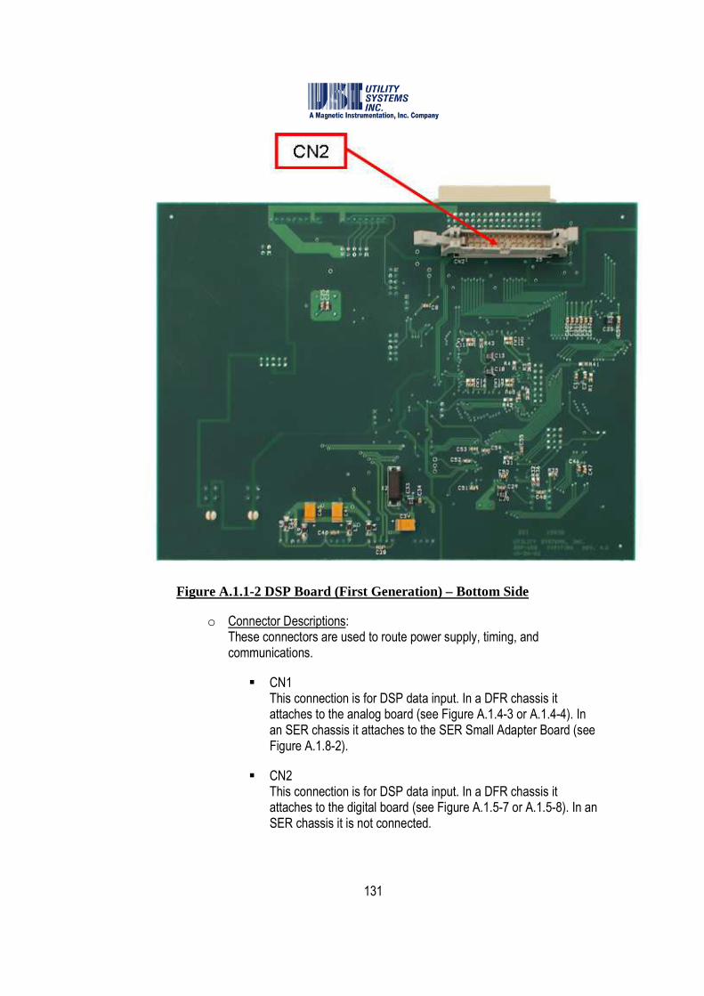
131
Figure A.1.1-2 DSP Board (First Generation) – Bottom Side
o Connector Descriptions: These connectors are used to route power supply, timing, and communications.
� CN1 This connection is for DSP data input. In a DFR chassis it attaches to the analog board (see Figure A.1.4-3 or A.1.4-4). In an SER chassis it attaches to the SER Small Adapter Board (see Figure A.1.8-2).
� CN2 This connection is for DSP data input. In a DFR chassis it attaches to the digital board (see Figure A.1.5-7 or A.1.5-8). In an SER chassis it is not connected.
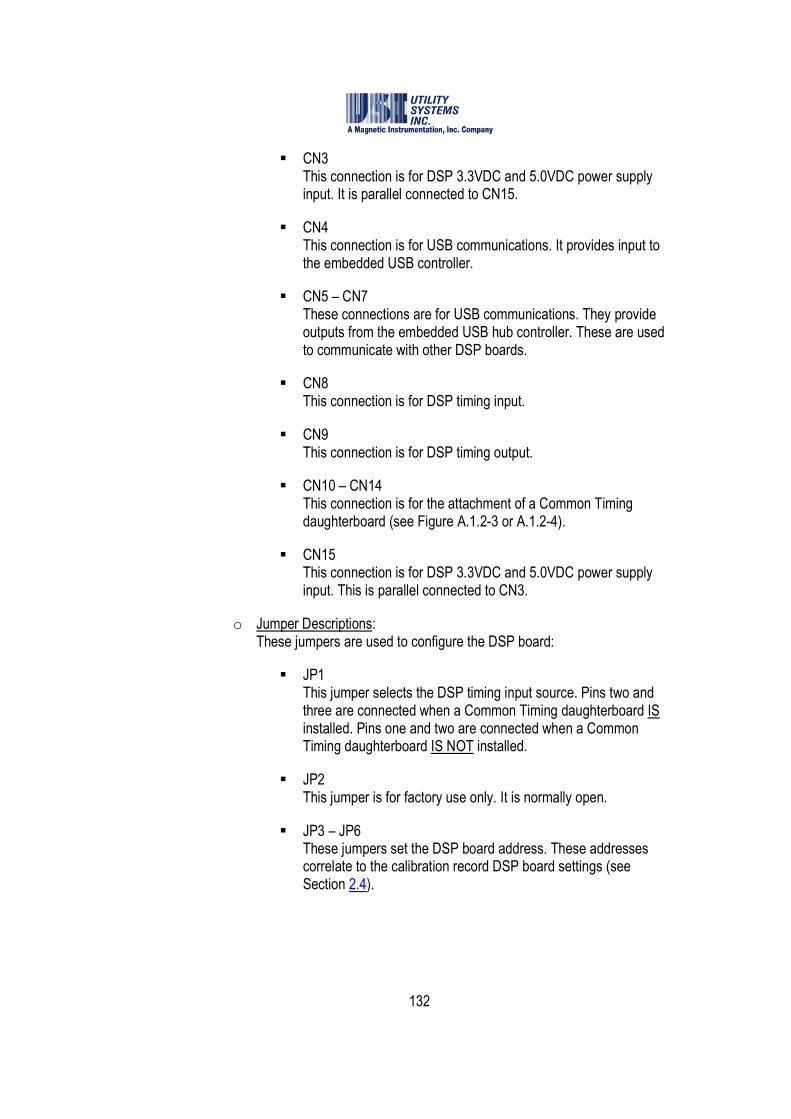
132
� CN3 This connection is for DSP 3.3VDC and 5.0VDC power supply input. It is parallel connected to CN15.
� CN4 This connection is for USB communications. It provides input to the embedded USB controller.
� CN5 – CN7 These connections are for USB communications. They provide outputs from the embedded USB hub controller. These are used to communicate with other DSP boards.
� CN8 This connection is for DSP timing input.
� CN9 This connection is for DSP timing output.
� CN10 – CN14 This connection is for the attachment of a Common Timing daughterboard (see Figure A.1.2-3 or A.1.2-4).
� CN15 This connection is for DSP 3.3VDC and 5.0VDC power supply input. This is parallel connected to CN3.
o Jumper Descriptions: These jumpers are used to configure the DSP board:
� JP1 This jumper selects the DSP timing input source. Pins two and three are connected when a Common Timing daughterboard IS installed. Pins one and two are connected when a Common Timing daughterboard IS NOT installed.
� JP2 This jumper is for factory use only. It is normally open.
� JP3 – JP6 These jumpers set the DSP board address. These addresses correlate to the calibration record DSP board settings (see Section 2.4).
133
Figure A.1.1-3 DSP Board Address Jumpers
� JP7 This jumper is for factory use only. It is normally open.
� JP10 This jumper is for factory use only. It is normally open.
� JP11 This jumper is for factory use only. Pins two and three are factory connected.
� JP12 This jumper is for factory use only. It is normally open.
134
� JT These jumpers are for factory use only. Pins seven and eight are factory connected; pins nine and ten are factory connected.
o LED Indicators: These indicate the following:
� D1 This LED is RED in color and indicates +5VDC is present.
� D2 This is GREEN in color and indicates +3.3VDC is present.
� D3 This is GREEN in color and indicates USB connection is detected.
� D4 This is RED in color and indicates USB power is present.
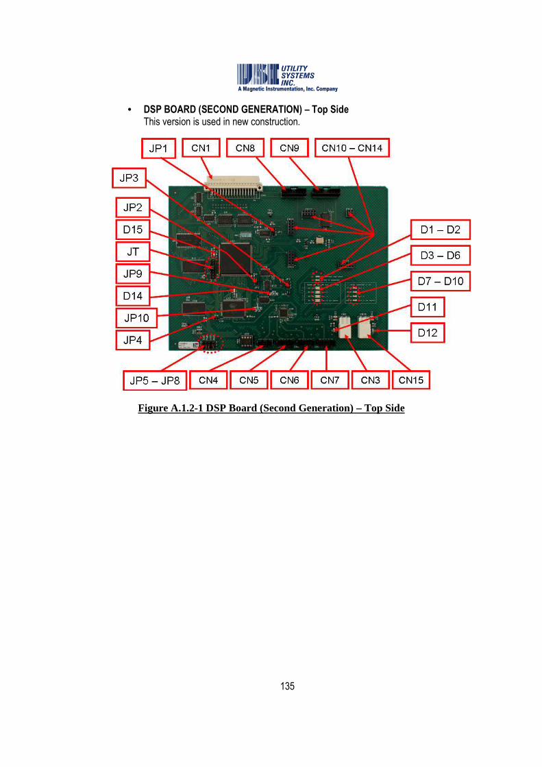
135
• DSP BOARD (SECOND GENERATION) – Top Side This version is used in new construction.
Figure A.1.2-1 DSP Board (Second Generation) – Top Side

136
Figure A.1.2-2 DSP Board (Second Generation) – Bottom Side
o Connector Descriptions: These connectors are used to route power supply, timing, and communications.
� CN1 This connection is for DSP data input. In a DFR chassis, this attaches to the analog board (see Figure A.1.4-3 or A.1.4-4). In an SER chassis this attaches to the SER Small Adapter Board (see Figure A.1.8-2).
� CN2 This connection is for DSP data input. In a DFR chassis this attaches to the digital board (see Figure A.1.5-7 or A.1.5-8). In an SER chassis this is not connected.
� CN3 This connection is for DSP 3.3VDC and 5.0VDC power supply inputs. It is parallel connected to CN15.
137
� CN4 This connection is for USB communications. It provides input to the embedded USB controller.
� CN5 – CN7 This connection is for USB communications. It provides output from the embedded USB hub controller used to communicate with other DSP boards.
� CN8 This connection is for DSP timing input.
� CN9 This connection is for DSP timing output.
� CN10 – CN14 This connection is for the attachment of a Common Timing daughterboard (see Figure A.1.2-3 or A.1.2-4).
� CN15 This connection is for DSP 3.3VDC and 5.0VDC power supply input. It is parallel connected to CN3.
o Jumper Descriptions: These jumpers are used to configure the DSP board:
� JP1 This jumper determines the DSP timing input source. Connect pins two and three when a Common Timing daughterboard IS installed. Connect pins one and two when a Common Timing daughterboard IS NOT installed.
� JP2 This jumper is for factory use only. Pins two and three are factory connected.
� JP3 This jumper is for factory use only. It is normally open.
� JP4 This jumper is for factory use only. It is normally open.
� JP5 – JP8 These jumpers set the DSP board address. These addresses correlate to the calibration record DSP board settings (see Section 2.4).

138
Figure A.1.2-3 DSP Board Address Jumpers
� JP9 This jumper is for factory use only. Pins two and three are factory connected.
� JP10 This jumper is for factory use only. Pins one and two are factory connected.
� JT These jumpers are for factory use only. Pins seven and eight are factory connected; pins nine and ten are factory connected.
139
o LED Indicator Descriptions: These indicate the following:
� D1 This indicates the USB connection is High Speed (480Mbs).
� D2 This indicates a suspended USB connection.
� D3 This indicates a USB connection to CN5.
� D4 This indicates a USB connection to CN6.
� D5 This indicates a USB connection to CN7.
� D6 This indicates that the on-board USB controller is connected to the USB hub.
� D7 This indicates an error on the USB connection to CN5.
� D8 This indicates an error on the USB connection to CN6.
� D9 This indicates an error on the USB connection to CN7.
� D10 This indicates an error on the USB controller connection to the USB hub.
� D11 This LED is RED in color and indicates the presence of +5VDC.
� D12 This LED is RED in color and indicates the presence of +3.3VDC.
� D14 This indicator is not used.
� D15 This indicator is not used.
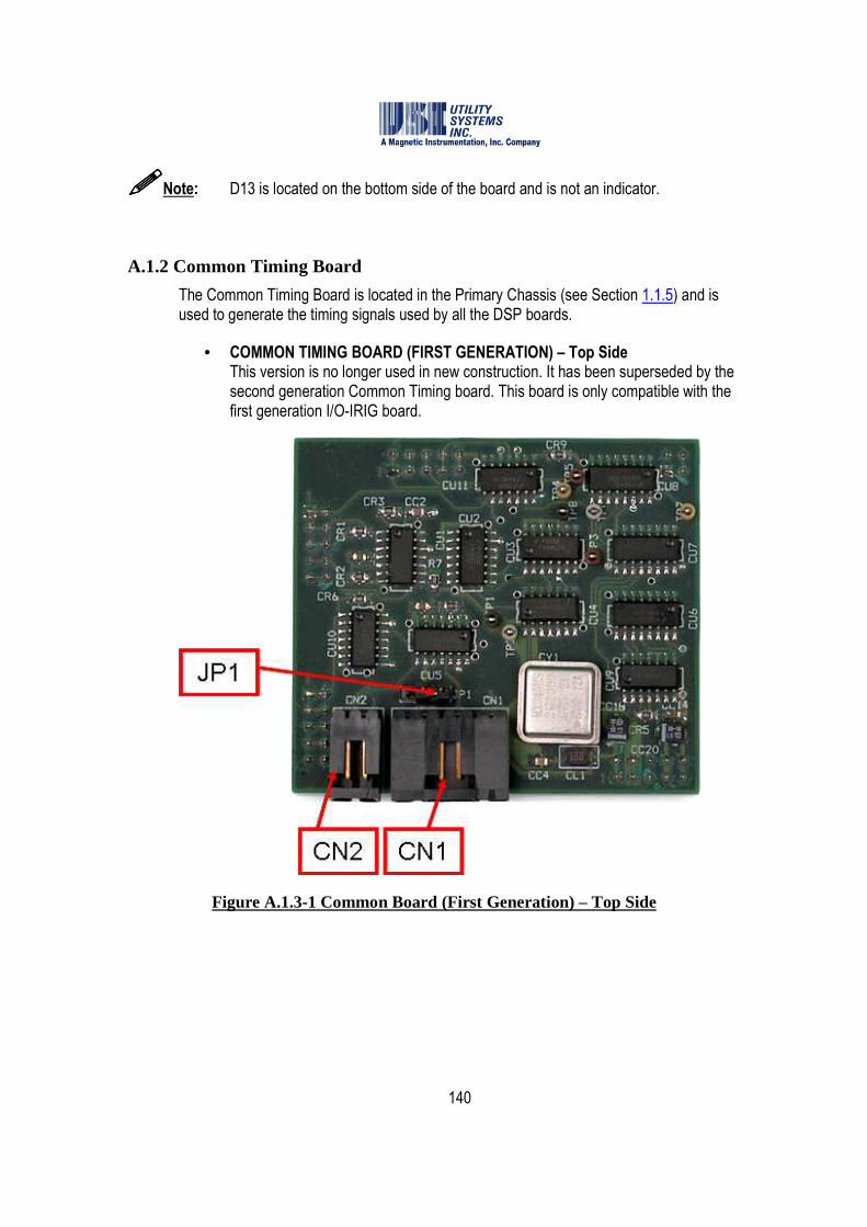
140
����Note: D13 is located on the bottom side of the board and is not an indicator.
A.1.2 Common Timing Board
The Common Timing Board is located in the Primary Chassis (see Section 1.1.5) and is used to generate the timing signals used by all the DSP boards.
• COMMON TIMING BOARD (FIRST GENERATION) – Top Side This version is no longer used in new construction. It has been superseded by the second generation Common Timing board. This board is only compatible with the first generation I/O-IRIG board.
Figure A.1.3-1 Common Board (First Generation) – Top Side
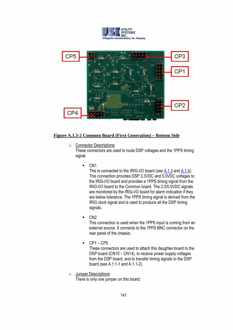
141
Figure A.1.3-2 Common Board (First Generation) – Bottom Side
o Connector Descriptions: These connectors are used to route DSP voltages and the 1PPS timing signal.
� CN1 This is connected to the IRIG-I/O board (see A.1.3 and A.1.4). This connection provides DSP 3.3VDC and 5.0VDC voltages to the IRIG-I/O board and provides a 1PPS timing signal from the IRIG-I/O board to the Common board. The 3.3/5.0VDC signals are monitored by the IRIG-I/O board for alarm indication if they are below tolerance. The 1PPS timing signal is derived from the IRIG clock signal and is used to produce all the DSP timing signals.
� CN2 This connection is used when the 1PPS input is coming from an external source. It connects to the 1PPS BNC connector on the rear panel of the chassis.
� CP1 – CP5 These connectors are used to attach this daughter-board to the DSP board (CN10 – CN14), to receive power supply voltages from the DSP board, and to transfer timing signals to the DSP board (see A.1.1-1 and A.1.1-2).
o Jumper Descriptions: There is only one jumper on this board:

142
� JP1 This jumper is used to select the source of the 1PPS input timing signal. The default postion connects pins two and three which selects the 1PPS timing signal from the IRIG-I/O board. Connecting pins one and two selects the 1PPS timing signal from an external source.
• COMMON TIMING BOARD (SECOND GENERATION) This version is used in new construction and is backward compatible with the first generation I/O-IRIG board.
Figure A.1.4-1 Common Board (Second Generation) – Top Side

143
Figure A.1.4-2 Common Board (Second Generation) – Bottom Side
o Connector Descriptions: These connectors are used to route DSP voltages and the 1PPS timing signal.
� CN1 This is connected to the IRIG-I/O board (see A.1.3 and A.1.4). This connection provides DSP 3.3VDC and 5.0VDC voltages to the IRIG-I/O board and provides a 1PPS timing signal from the IRIG-I/O board to the Common Board. The 3.3/5.0VDC signals are monitored by the IRIG-I/O board for alarm indication if they are below tolerance. The 1PPS timing signal is derived from the IRIG clock signal and is used to produce all the DSP timing signals.
� CN2 This connection is used when the 1PPS input is coming from an external source. It connects to the 1PPS BNC connector on the rear panel of the chassis.
� CP1 – CP5 These connectors are used to attach this daughter-board to the DSP board (CN10 – CN14), to receive power supply voltages from the DSP board, and to transfer timing signals to the DSP board (see A.1.1-1 and A.1.1-2).
o Jumper Descriptions: There are only two jumpers on this board:
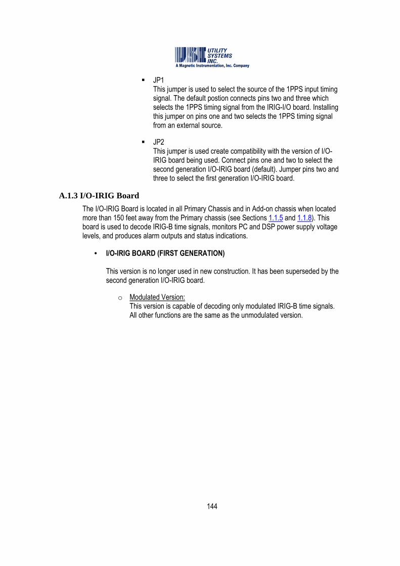
144
� JP1 This jumper is used to select the source of the 1PPS input timing signal. The default postion connects pins two and three which selects the 1PPS timing signal from the IRIG-I/O board. Installing this jumper on pins one and two selects the 1PPS timing signal from an external source.
� JP2 This jumper is used create compatibility with the version of I/O-IRIG board being used. Connect pins one and two to select the second generation I/O-IRIG board (default). Jumper pins two and three to select the first generation I/O-IRIG board.
A.1.3 I/O-IRIG Board
The I/O-IRIG Board is located in all Primary Chassis and in Add-on chassis when located more than 150 feet away from the Primary chassis (see Sections 1.1.5 and 1.1.8). This board is used to decode IRIG-B time signals, monitors PC and DSP power supply voltage levels, and produces alarm outputs and status indications.
• I/O-IRIG BOARD (FIRST GENERATION) This version is no longer used in new construction. It has been superseded by the second generation I/O-IRIG board.
o Modulated Version: This version is capable of decoding only modulated IRIG-B time signals. All other functions are the same as the unmodulated version.
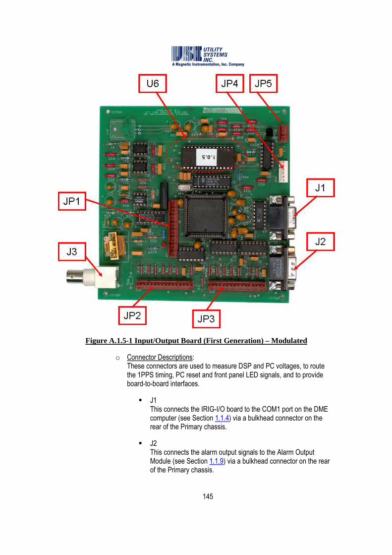
145
Figure A.1.5-1 Input/Output Board (First Generation) – Modulated
o Connector Descriptions: These connectors are used to measure DSP and PC voltages, to route the 1PPS timing, PC reset and front panel LED signals, and to provide board-to-board interfaces.
� J1 This connects the IRIG-I/O board to the COM1 port on the DME computer (see Section 1.1.4) via a bulkhead connector on the rear of the Primary chassis.
� J2 This connects the alarm output signals to the Alarm Output Module (see Section 1.1.9) via a bulkhead connector on the rear of the Primary chassis.

146
� J3 This connects to the modulated output of the GPS clock receiver (see Section 1.1.1) via a bulkhead connector on the rear of the Primary chassis.
� JP1 This connects the watch-dog reset output to the DME computer (see Section 1.1.4) via a bulkhead connector on the rear of the Primary chassis.
� JP2 and JP3 These connect to the Primary chassis front panel LED indicators.
� JP4 This connects the DSP 3.3VDC and 5.0VDC inputs from the Common Timing board for level monitoring, and 1PPS to the Common Timing board.
� JP5 This connects the PC Volt 5VDC, +12VDC, and -12VDC inputs from the Common Timing board for level monitoring.
� U6 This socket connects the EPROM which contains the board firmware. The label on the EPROM indicates the firmware version.
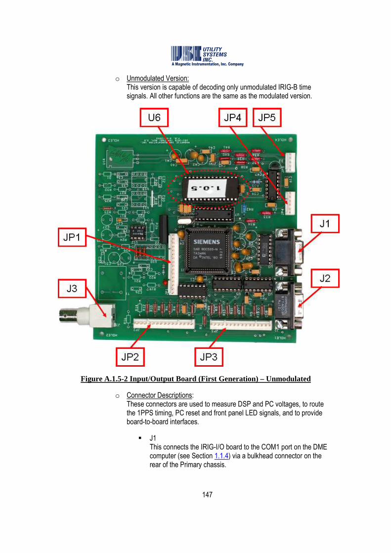
147
o Unmodulated Version: This version is capable of decoding only unmodulated IRIG-B time signals. All other functions are the same as the modulated version.
Figure A.1.5-2 Input/Output Board (First Generation) – Unmodulated
o Connector Descriptions: These connectors are used to measure DSP and PC voltages, to route the 1PPS timing, PC reset and front panel LED signals, and to provide board-to-board interfaces.
� J1 This connects the IRIG-I/O board to the COM1 port on the DME computer (see Section 1.1.4) via a bulkhead connector on the rear of the Primary chassis.
148
� J2 This connects the alarm output signals to the Alarm Output Module (see Section 1.1.9) via a bulkhead connector on the rear of the Primary chassis.
� J3 This connects to the unmodulated output of the GPS clock receiver (see Section 1.1.1) via a bulkhead connector on the rear of the Primary chassis.
� JP1 This connects the watch-dog reset output to the DME computer (see Section 1.1.4) via a bulkhead connector on the rear of the Primary chassis.
� JP2 and JP3 These connect to the Primary chassis front panel LED indicators.
� JP4 This connects the DSP 3.3VDC and 5.0VDC inputs from the Common Timing board for level monitoring, and 1PPS to the Common Timing board.
� JP5 This connects the PC Volt 5VDC, +12VDC, and -12VDC inputs from the Common Timing board for level monitoring.
� U6 This socket connects the EPROM which contains the board firmware. The label on the EPROM indicates the firmware version.
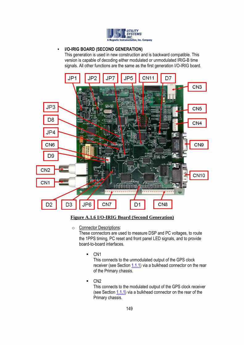
149
• I/O-IRIG BOARD (SECOND GENERATION) This generation is used in new construction and is backward compatible. This version is capable of decoding either modulated or unmodulated IRIG-B time signals. All other functions are the same as the first generation I/O-IRIG board.
Figure A.1.6 I/O-IRIG Board (Second Generation)
o Connector Descriptions: These connectors are used to measure DSP and PC voltages, to route the 1PPS timing, PC reset and front panel LED signals, and to provide board-to-board interfaces.
� CN1 This connects to the unmodulated output of the GPS clock receiver (see Section 1.1.1) via a bulkhead connector on the rear of the Primary chassis.
� CN2 This connects to the modulated output of the GPS clock receiver (see Section 1.1.1) via a bulkhead connector on the rear of the Primary chassis.
150
� CN3 This connects the board input power.
� CN4 This connects the DSP 3.3VDC and 5.0VDC inputs from the Common Timing board for level monitoring, and 1PPS to the Common Timing board.
� CN5 This connects the PC Volt 5VDC, +12VDC, and -12VDC inputs from the Common Timing board for level monitoring.
� CN6 This connects the watch-dog reset output to the DME computer (see Section 1.1.4) via a bulkhead connector on the rear of the Primary chassis.
� CN7 and CN8 These connect to the Primary chassis front panel LED indicators.
� CN9 This connects the IRIG-I/O board to the COM1 port on the DME computer (see Section 1.1.4) via a bulkhead connector on the rear of the Primary chassis.
� CN10 This connects the alarm output signals to the Alarm Output Module (see Section 1.1.9) via a bulkhead connector on the rear of the Primary chassis.
� CN11 This connection is a JTAG interface used to install or update firmware to the onboard EEPROM.
o Jumper Descriptions: These jumpers are used to configure the I/O-IRIG board:
� JP1 This jumper is used to configure gain control on the IRIG-B input. The default setting connects pins two and three (Position A) for automatic gain control. This setting provides additional gain and is required when the IRIG-B signal is low due to long cable feed from the GPS clock. Connect pins one and two (Position F) for fixed gain control.
� JP2 This jumper is used to configure the board for modulated or
151
unmodulated IRIG signals. Connect pins one and two for a modulated IRIG input. Connect pins two and three for an unmodulated input.
� JP3 This jumper is used for factory troubleshooting only, and is not installed. Connecting pins one and two holds the board in reset mode.
� JP4 This jumper is used to configure the watchdog circuit. The default setting connects pins one and two which enables the watchdog. Connecting pins two and three disables the watchdog.
� JP5 This jumper is used for factory troubleshooting only, and is not installed. Connecting pins one and two holds the Real Time Clock (RTC) in reset mode.
� JP6 This jumper is used to enable or disable the PC reset connector (CN6). Connect pins one and two to enable the PC reset connector. Connect pins two and three to disable the PC reset connector.
� JP7 This jumper is used for factory troubleshooting only, and is not installed. Connecting pins one and two sends a reset to the microprocessor.
o LED Indicator Descriptions: These indicate the following:
� D1 This indicates 5VDC power supply is present.
� D3 This indicates a system reset signal was received.
� D7 This blinks to indicate sync to IRIG and that a 1PPS signal is being generated.
� D8 This indicates a microprocessor reset condition.

152
� D9 This indicates a FLAG4 signal is present.
A.1.4 Analog Input Circuitry
The Analog Input Circuitry is located in the Primary and Add-on Chassis (see Sections 1.1.5 through 1.1.8) and is used to measure and digitize the analog input signals. All generations of analog assemblies have a total of eight inputs which accept AC or DC voltage or current signals. The input terminals for all generations are identified as follows:
� V1 Accepts voltage signals with full scale range from 41Vrms to 400Vrms.
� V2
Accepts voltage signals with full scale range from 1.5Vrms to 40Vrms.
� I
Accepts direct current signals and is rated for up to 200Arms for two seconds.
� C
This terminal is common to the input terminals.
• HIGH-VOLTAGE ANALOG BOARD (FIRST GENERATION) This generation is no longer used in new construction. It has been superseded by the second generation analog input assembly. This board uses precision voltage dividers and current shunt resistors to reduce the analog input levels, and uses by-pass surge protection capacitors to attenuate incoming transient spikes.
o Dual Board Version: This assembly consists of one voltage divider and shunt board and one surge protection by-pass daughter-board.
Figure A.1.7-1 High-Voltage Analog Board (Dual Board Version) – Top Side
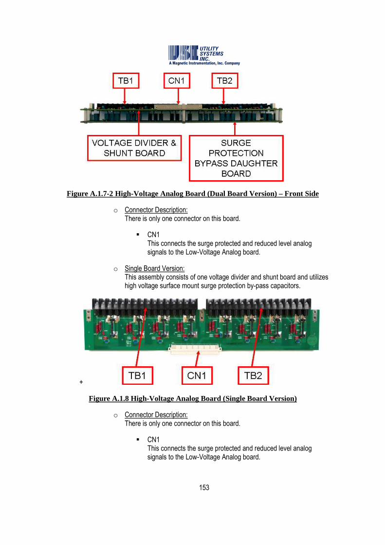
153
Figure A.1.7-2 High-Voltage Analog Board (Dual Board Version) – Front Side
o Connector Description: There is only one connector on this board.
� CN1 This connects the surge protected and reduced level analog signals to the Low-Voltage Analog board.
o Single Board Version: This assembly consists of one voltage divider and shunt board and utilizes high voltage surface mount surge protection by-pass capacitors.
+
Figure A.1.8 High-Voltage Analog Board (Single Board Version)
o Connector Description: There is only one connector on this board.
� CN1 This connects the surge protected and reduced level analog signals to the Low-Voltage Analog board.
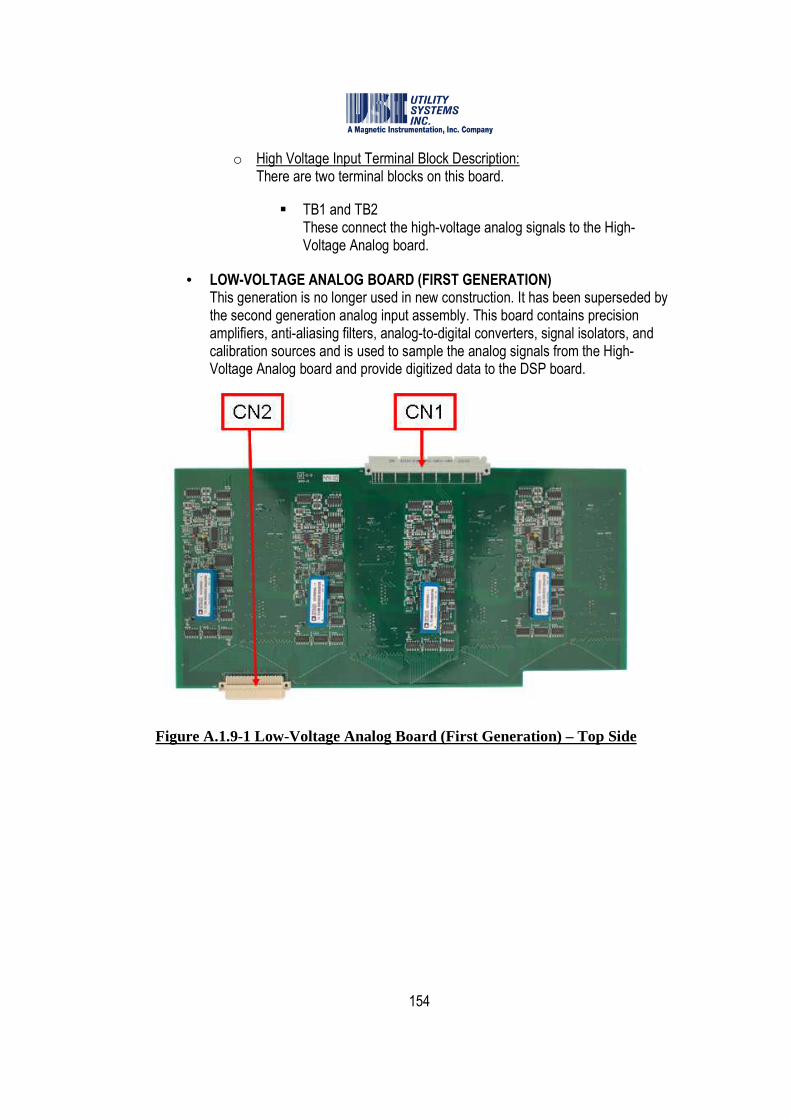
154
o High Voltage Input Terminal Block Description: There are two terminal blocks on this board.
� TB1 and TB2 These connect the high-voltage analog signals to the High-Voltage Analog board.
• LOW-VOLTAGE ANALOG BOARD (FIRST GENERATION) This generation is no longer used in new construction. It has been superseded by the second generation analog input assembly. This board contains precision amplifiers, anti-aliasing filters, analog-to-digital converters, signal isolators, and calibration sources and is used to sample the analog signals from the High-Voltage Analog board and provide digitized data to the DSP board.
Figure A.1.9-1 Low-Voltage Analog Board (First Generation) – Top Side

155
Figure A.1.9-2 Low-Voltage Analog Board (First Generation) – Bottom Side
o Connector Description: There are only two connectors on this board:
� CN1 This connects the boards inputs to the High Voltage Analog board.
� CN2 This connects the sample clock signals from the DSP board and connects the digitized data output to the DSP board.
o 4.8kHz Version: This version contains a 2-pole low-pass anti-alliasing filter with a cutoff frequency of 4.8kHz.
o 10kHz Version: This version contains a 2-pole low-pass anti-alliasing filter with a cutoff frequency of 10kHz.
• ANALOG BOARD (SECOND GENERATION) This generation is used in new construction and is backward compatible.
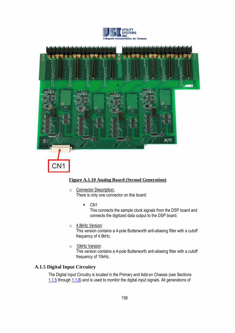
156
Figure A.1.10 Analog Board (Second Generation)
o Connector Description: There is only one connector on this board:
� CN1 This connects the sample clock signals from the DSP board and connects the digitized data output to the DSP board.
o 4.8kHz Version: This version contains a 4-pole Butterworth anti-aliasing filter with a cutoff frequency of 4.8kHz.
o 10kHz Version: This version contains a 4-pole Butterworth anti-aliasing filter with a cutoff frequency of 10kHz.
A.1.5 Digital Input Circuitry
The Digital Input Circuitry is located in the Primary and Add-on Chassis (see Sections 1.1.5 through 1.1.8) and is used to monitor the digital input signals. All generations of
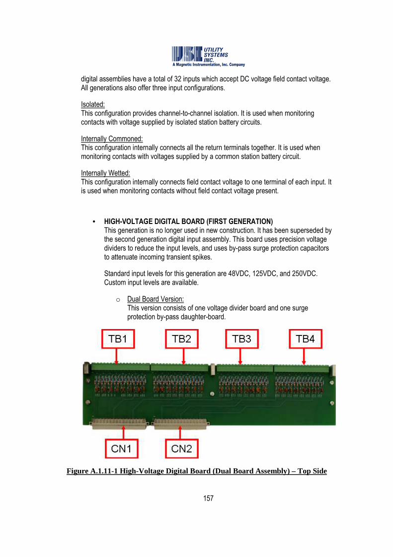
157
digital assemblies have a total of 32 inputs which accept DC voltage field contact voltage. All generations also offer three input configurations.
Isolated: This configuration provides channel-to-channel isolation. It is used when monitoring contacts with voltage supplied by isolated station battery circuits.
Internally Commoned: This configuration internally connects all the return terminals together. It is used when monitoring contacts with voltages supplied by a common station battery circuit.
Internally Wetted: This configuration internally connects field contact voltage to one terminal of each input. It is used when monitoring contacts without field contact voltage present.
• HIGH-VOLTAGE DIGITAL BOARD (FIRST GENERATION) This generation is no longer used in new construction. It has been superseded by the second generation digital input assembly. This board uses precision voltage dividers to reduce the input levels, and uses by-pass surge protection capacitors to attenuate incoming transient spikes.
Standard input levels for this generation are 48VDC, 125VDC, and 250VDC. Custom input levels are available.
o Dual Board Version: This version consists of one voltage divider board and one surge protection by-pass daughter-board.
Figure A.1.11-1 High-Voltage Digital Board (Dual Board Assembly) – Top Side
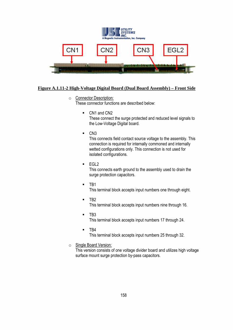
158
Figure A.1.11-2 High-Voltage Digital Board (Dual Board Assembly) – Front Side
o Connector Description: These connector functions are described below:
� CN1 and CN2 These connect the surge protected and reduced level signals to the Low-Voltage Digital board.
� CN3 This connects field contact source voltage to the assembly. This connection is required for internally commoned and internally wetted configurations only. This connection is not used for isolated configurations.
� EGL2 This connects earth ground to the assembly used to drain the surge protection capacitors.
� TB1 This terminal block accepts input numbers one through eight.
� TB2 This terminal block accepts input numbers nine through 16.
� TB3 This terminal block accepts input numbers 17 through 24.
� TB4 This terminal block accepts input numbers 25 through 32.
o Single Board Version: This version consists of one voltage divider board and utilizes high voltage surface mount surge protection by-pass capacitors.

159
Figure A.1.12 High-Voltage Digital Board (Single Board Assembly)
o Connector Description: The connectors of this assembly are the same as the double board assembly, with the following exceptions:
� CN3 and CN4 These connectors supply field contact source voltage to the assembly via rear panel terminal block. They are parallel connected to allow daisy-chain connections to other High-Voltage Digital board assemlies within the chassis. This connection is required for internally commoned and internally wetted configurations only. This connection is not used for isolated configurations.
� EGL1 This connector is unused on this assembly. The aluminum board mounting blocks are used to connect earth ground to the assembly directly to the chassis rear panel and drain the surge protection capacitors.
• LOW-VOLTAGE DIGITAL BOARD (FIRST GENERATION) This generation is no longer used in new construction. It has been superseded by the second generation digital input assembly. This board contains optical isolators and is used to monitor the signals from the High-Voltage Digital board and provide digitized data to the DSP board.
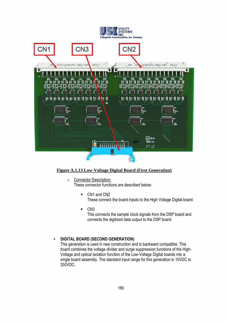
160
Figure A.1.13 Low-Voltage Digital Board (First Generation)
o Connector Description: These connector functions are described below:
� CN1 and CN2 These connect the board inputs to the High Voltage Digital board.
� CN3 This connects the sample clock signals from the DSP board and connects the digitized data output to the DSP board.
• DIGITAL BOARD (SECOND GENERATION) This generation is used in new construction and is backward compatible. This board combines the voltage divider and surge suppression functions of the High-Voltage and optical isolation function of the Low-Voltage Digital boards into a single board assembly. The standard input range for this generation is 10VDC to 250VDC.
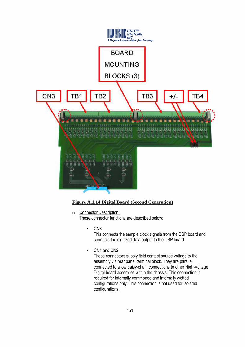
161
Figure A.1.14 Digital Board (Second Generation)
o Connector Description: These connector functions are described below:
• CN3 This connects the sample clock signals from the DSP board and connects the digitized data output to the DSP board.
• CN1 and CN2 These connectors supply field contact source voltage to the assembly via rear panel terminal block. They are parallel connected to allow daisy-chain connections to other High-Voltage Digital board assemlies within the chassis. This connection is required for internally commoned and internally wetted configurations only. This connection is not used for isolated configurations.
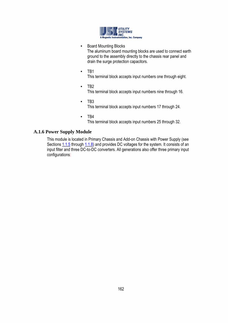
162
• Board Mounting Blocks The aluminum board mounting blocks are used to connect earth ground to the assembly directly to the chassis rear panel and drain the surge protection capacitors.
• TB1 This terminal block accepts input numbers one through eight.
• TB2 This terminal block accepts input numbers nine through 16.
• TB3 This terminal block accepts input numbers 17 through 24.
• TB4 This terminal block accepts input numbers 25 through 32.
A.1.6 Power Supply Module
This module is located in Primary Chassis and Add-on Chassis with Power Supply (see Sections 1.1.5 through 1.1.8) and provides DC voltages for the system. It consists of an input filter and three DC-to-DC converters. All generations also offer three primary input configurations:

163
Figure A.1.15-1 Power Supply Assembly
o 250Vdc Input: The input range of this version is 200 to 400VDC.
o 125Vdc Input: The input range of this version is 90 to 200VDC.
o 48Vdc Input: The input range of this version is 42 to 60VDC.
• DC-to-DC Converter Module These modules provide isolated DC voltages for system use.

164
Figure A.1.15-2 DC-to-DC Converter module
o Connector Description: These connector functions are described below:
• S1 – S4 These terminals connect the input voltage from the station battery.
• S5 – S12 These terminals connect the output voltage from the DC-to-DC converter to the system.
o Fuse Description: The fuse function is described below:
• F1 This fuse limits the input current to the DC-to-DC converter module.

165
Glossary
1
1 ph. PF
Abbreviation for Single-Phase Power Factor
1 ph. Vr
Abbreviation for Single-Phase Reactive Power (Vr is an abbreviation for VAR )
1 ph. W
Abbreviation for Single-Phase Real Power
3
3I0
Acronym for Three-I-Zero. Abbreviation for inverse of Three-Phase Neutral Current
3 ph. PF
Abbreviation for Three-Phase Power Factor
3 ph. Vr
Abbreviation for Three-Phase Reactive Power (Vr is an abbreviation for VAR)
3 ph. W
Abbreviation for Three-Phase Real Power
A
ANSI
Acronym for American National Standards Institute, a publisher of standards
ASCII
Acronym for American Standard Code for Information Interchange, an eight-bit character-based code
Auto
Abbreviation for Automatic
B
Baud (rate)
The unit for signaling rate of a communications circuit. It is equal to the number of transitions (voltage or frequency changes) that are made per second. Often used erroneously as equivalent to bits per second. Baud and bits per second are equivalent only at rates of 300/second and lower. A V.22bis modem generates 1200 bps at 600 baud. Baud was named after French engineer Jean Maurice Emile Baudot (1845-1903).
Binary
The binary numeral system, or base-2 number system, represents numeric values using two symbols, 0 and 1.
BMP
A graphics file in bitmap (bump) format; these files have a .bmp extension and can be sent to the Windows Clipboard
C
Cal.
Abbreviation for Calibration
Cal Rec
Or Cal. Rec. Abbreviation for Calibration Record
Calibration Record
The Calibration Record (Cal Rec) contains the channel assignments for the DME system. This record contains the sample rate, fault length parameters, analog and digital input channel parameters, and analog trigger parameters. This record may be created and edited at the remote units or at the master stations. See Section 3.2.
166
CD-ROM
Abbreviation for Compact Disc – Read-Only Memory. This is a type of portable data storage medium used to transport software and data. It is similar in appearance to a common audio CD.
Ch
Abbreviation for Channel
COM
Abbreviation for Communication as in COM Port
Com Bd
Abbreviation for Common Board. The Common board is mounted on a DSP board and is used in local distributed systems. See Section 3.2.4.
Comm
Or Comm. Abbreviation for Communication
COMTRADE
Acronym for Common Format for Transient Data Exchange. Source: IEEE Std C37.111-1999, IEEE Standard Common Format for Transient Data Exchange (COMTRADE) for Power Systems.
COMNAMES
Standardized file naming convention, part of IEEE Std C37.232, IEEE Standard Common Format for Transient Data Exchange (COMTRADE) for Power Systems.
Config
Or Config. Abbreviation for Configuration.
Cont-Rec
Abbreviation for Continuous Recording. See Section 2.1.5.
CPU
Abbreviation for Central Processing Unit (or processor), the primary functional element of a computer.
CT
Acronym for Current Transformer
CT Ratio
CT refers to Current Transformer, a type of instrument transformer used to measure a current in an electrical power system. The value entered in this field is the turns ratio of primary to secondary of the transformer (e.g. 240:1). See PT Ratio.
D
dB
Decibel, the unit of power-level comparison; technically, the base-10 logarithm of a ratio of two power levels
Descripts
Abbreviation for Descriptions
DFR
Acronym for Digital Fault Recorder. A subsystem of the DME.
DFR/SER
Acronym for Digital Fault Recorder/Sequence of Events Recorder. Subsystems of the DME.
Dial-up
A method whereby the various stations of the DME system communicate with each other via a telephone system
Diag
Abbreviation for Diagnostic
Diff
Abbreviation for Difference
Disturbance
An unplanned event that produces an abnormal system condition.
167
DME
Acronym for Disturbance Monitoring Equipment (i.e.
Digital Fault Recorder, Sequence of Events Recorder, and Disturbance Monitoring System)
DNP3
Acronym for Distributed Network Protocol 3: A set of communications protocols used between components in process automation systems. It is mainly used by electric and water utilities. The DNP3 protocol is compliant with IEC 62351-5. It is referenced in IEEE 1379-2000 which recommends a set of best practices for system security.
DSP
Acronym for Digital Signal Processor. This is a type of integrated circuit used in the Model 2002 Disturbance Monitoring Equipment (DME).
DST
Acronym for Daylight Saving Time. See Section 3.1.2.
E
Electronic mail routed over the Internet or Intranet. See SMTP/POP3.
Ethernet
Ethernet is a family of computer networking technologies for Local Area Networks (LANs). It has been standardized as IEEE 802.3 and has been in use since the early 1980s. It has largely replaced the competing technologies: token ring, FDDI, and ARCNET.
EV#
Abbreviation for Event Number
Ext
Abbreviation for External
F
Fax
Abbreviation for facsimile. Facsimile (fax) machines interchange text and graphics in a low-resolution half-tone page raster format over telephone systems.
FID
Abbreviation for Fault Identification (ID) number
FIFO
Acronym for First In First Out, a method of data storage and retrieval
FLAG4
This signal generated is used to synchronize the timing of the DSP boards.
Freq
Abbreviation for Frequency. In this document, Frequency is used both as the power system line frequency (nominally 50 Hz or 60Hz) and as the sampling rate of the analog-to-digital converters.
G
GMT
Acronym for Greenwich Mean Time
GPS
Acronym for Global Positioning System. GPS is used to time synchronize the Disturbance Monitoring Equipment (DME). See Section 1.
GSP
Acronym for Graphic Signal Processing.
H
Horz
Abbreviation for Horizontal
168
I
ID
Abbreviation for Identification, Identifier, Identify, or Ident
IEEE
Acronym for the Institute of Electrical and Electronics Engineers, a publisher of standards
IN#
Abbreviation for Input (Channel) Number
Info
Also Info. Abbreviation for Information
I/O
Abbreviation for Input/Output. In this system, however, there are I/O Boards that contain more than just input/out circuitry. See Section 1.1.5.
IP address
An Internet Protocol (IP) Address is a numerical label assigned to devices participating in a computer network that uses Internet Protocol (IP) for communication between its nodes.
IRIG-B
IRIG-B refers to a serial time code format. It is a timing signal transmitted at a 100 bps rate. IRIG-B sends Day of Year, Hour, Minute and Second data on a 1 KHz carrier. It has a one-second update rate. IRIG is an acronym for Inter Range Instrumentation Group.
J
JPEG
Acronym for Joint Photographic Expert Group – a commonly used standard for digitizing photographic images
K-L
LAN
Acronym for Local Area Network
LCD
Acronym for Liquid Crystal Display
LDC
Acronym for Lightning Data Correlation. LDC is an
optional feature of the USIMaster© System. Adding
this option enables the client to correlate fault data with lightning strike data.
LED
Acronym for Light-Emitting Diode, a solid-state light source.
Lightning
An electric discharge that occurs in the atmosphere between clouds or between clouds and ground.
Loc
Or Loc. Abbreviation for Location
LogF
Abbreviation for Logic Filter
LT
Abbreviation for Long Term Fault
M
Magnetic Instrumentation, Inc.
The parent company of Utility Systems, Inc. (USI).
Max
Or Max. Abbreviation for Maximum

169
Metafile
A graphics file format that can be sent to the Windows Clipboard or to a printer. These files have a .wmf (Windows Metafile) extension.
Meter
A feature on the Measurement Panels section of the Graphic Signal Processing screen. A meter provides the numerical value of a waveform parameter such as RMS voltage.
MIN
Abbreviation for Minimum
Modem
Contraction for MOdulator-DEModulator. In common usage, a modem is a bi-directional interface between a computer system and a communications system. In
the USIMaster© system, modems in the master unit
and in the remote units communicate bi-directionally via a telephone system, a LAN/WAN or the internet.
N-O
NC
Acronym for Normally Closed, describes a type of relay that has closed output contacts when de-energized (OFF state) and open output contacts when energized (ON state).
NO
Acronym for Normally Open, describes a type of relay that has open output contacts when de-energized (OFF state) and closed output contacts when energized (ON state).
Number of Cycles
To calculate an RMS value of a waveform, the number of cycles (periods) of the measurand waveform to be used in the calculation must be specified.
Optocoupler
A four-terminal (sometimes five-terminal) electronic component used to couple signals from high voltage electrical systems to low voltage electronic systems while providing electrical isolation between the two. Also known as an optoisolator, it consists of a light source and a light detector separated by an optically-transparent insulator. Its simplest embodiment uses a light-emitting diode and a photodiode separated by a thick layer of clear plastic.
Oscillography
1. A record containing sampled waveform data. 2. The science of sensing, recording, displaying, and analyzing time-varying phenomena.
P
panel
An area on the Graphic Signal Processing screen.
PC
Personal Computer
pcAnyWhere
Symantec pcAnywhere© (Host and Remote) is a third-party application supplied to allow remote-control accessibility and file transfer capabilities from the master station PC. It may be used remotely to install software updates, perform maintenance, and diagnostics via dial-up modem or Ethernet (LAN/WAN) communication media. See Symantec.
PDC
Acronym for Phasor Data Concentrator.
Phasor
A phase vector (phasor) is a representation of a sine wave whose amplitude (A), phase (θ), and frequency (ω) are time invariant. Use of phasors simplifies certain calculations by eliminating time (frequency) terms and leaving only amplitude and phase.

170
Ping
Ping is a computer network administration utility used to test whether a particular host is reachable across an Internet Protocol (IP) network. It also measures the round-trip time for packets sent from the local host to a destination computer, including the time delay in the host computer interfaces.
Use of the ping utility is usually described as pinging a host computer.
PLC
Acronym for Programmable Logic Controller
PMU
Acronym for Phasor Measurement Unit.
POP3
POP3 is an abbreviation for Post Office Protocol Version 3. POP is an application-layer Internet standard protocol used by local E-mail clients to retrieve E-mail from a remote server over a TCP/IP connection. Version 3 (POP3) is the current standard.
PT
Acronym for Potential Transformer.
PT Ratio
PT refers to Potential Transformer, a type of instrument transformer used to measure a voltage in an electrical power system. The value entered in this field is the turns ratio of primary to secondary of the transformer (e.g. 3000:1). See CT Ratio.
Q-R
Quick Panel
A selectable feature of the Graph Setup Group screen.
QSM
Abbreviation for Quick Summary
Qsum
Abbreviation for Quick Summary
Remote
Synonym for Digital Fault Recorder (DFR), a unit of the Disturbance Monitoring Equipment (DME) system, usually located remotely from the DME host computer.
RFL
Abbreviation for RFL Electronics, Inc. RFL is a manufacturer of communications equipment for the power utility industry.
RMS
Acronym for Root-Mean-Square
RS-232
RS-232 (Recommended Standard 232) is a standard for serial binary single-ended data and control signals connecting between a Data Terminal Equipment (DTE) and a Data Circuit-terminating Equipment (DCE). It is commonly used in computer serial ports. The controlling standard is Electronic Industries Association (EIA) RS-232C (1969). Current revision is Telecommunications Industry Association TIA-232-F (1997). In the personal computer industry RS-232 has been largely replaced by the USB interface standard. Industrial equipment and PLCs still use the RS-232-C standard port.
RTC
Acronym for Real Time Clock
S
Sag
A decrease between 0.1 and 0.9 per unit in RMS voltage or current at the power frequency, for durations from a half-cycle to one minute.
Scope©
Utility Systems, Inc. is the owner/producer/licensor of
the Scope©
application package
171
Screen
A visual display on a computer monitor is called a screen. USIMaster© is viewed on a family of screens, such as: System Configuration screen, Graphic Signal Processing (GSP) screen, USI Master Station screen, etc.
SER
Acronym for Sequence of Events Recorder, a type of Disturbance Monitoring Equipment used in the USI Disturbance Monitoring System.
ServiceMaster
An diagnostic/troubleshooting tool. Access is by System Configuration screen, Automation tab.
Shunt
A resistive device that provides an output voltage proportional to circuit current.
Single Ended
Or 1-ended (q.v.). A type of distance-to-fault calculation.
SMTP/POP3
Abbreviation for Simple Mail Transfer Protocol/Post Office Protocol Version 3. SMTP is an Internet standard for E-mail transmission across Internet Protocol (IP) networks (see TCP/IP). User-level applications typically use SMTP for transmission of E-mail messages and POP3 (q.v.) for reception of E-mail messages.
Start/Stop Time
Time Query method for LDC system. See Start Time/Duration method.
Start Time/Duration
Time Query method for LDC system See Start/Stop Time method.
Surge
A transient wave of voltage, current, or power in an electrical circuit.
Symantec
Abbreviation for Symantec Corporation, the publisher of Norton pcAnywhere©.
Sync
Abbreviation for Synchronize or Synchronization
Synchrophasor
A phasor calculated from data samples using a standard time signal as a reference for the measurement. Synchronized phasors from remote sites have a defined common phase relationship. See IEEE C37.118-2005 Standard for Synchrophasors for Power Systems, IEEE Power Engineering Society.
T
TCP/IP
The Internet Protocol Suite, commonly known as TCP/IP, is a four-layered set of communications protocols used for the Internet and other similar networks. Two of the most important protocols in the suite are the Transmission Control Protocol (TCP) and the Internet Protocol (IP), hence the common name.
Text/Data Only
An ASCII (q.v.) text format that can be sent to the Windows Clipboard; these files have a .txt or .dat extension; they can be viewed or printed by using a word processor.
THD
Acronym for Total Harmonic Distortion
TR#
Abbreviation for Trigger Number
U
UDP/IP
The Internet Protocol Suite, commonly known as TCP/IP (q.v.), is a four-layered set of communications
172
protocols used for the Internet and other similar networks. Two of the protocols in the suite are the User Diagram Protocol (UDP) and the Internet Protocol (IP), hence the common name.
With UDP, computer applications can send messages (datagrams). Datagrams may arrive out of order, appear duplicated, or go missing without notice. Time sensitive applications often use UDP because dropping of packets is preferable to waiting for delayed packets.
URL
Acronym for Uniform Resource Locator. In computing, a URL is a Uniform Resource Identifier (URI) that specifies where an identified resource is available and the mechanism for retrieving it. URL is often incorrectly used as a synonym for URI. The best-known example of a URL is the address of a web page on the World Wide Web, e.g. http://www.example.com.
USB
Acronym for Universal Serial Bus. It is a specification for a bus used to establish communication between devices and a host controller, usually a personal computer (PC). USB is a bit-serial bus in general use to connect peripherals such as mice, keyboards, digital cameras, printers, scanners, media players, flash drives, and external hard drives.
USI
Acronym for Utility Systems, Inc.
USIMaster©
Utility Systems, Inc. is the owner/producer/licensor of
the USIMaster©
application package.
USIRemote©
Utility Systems, Inc. is the owner/producer/licensor of
the USIRemote©
application package.
V
Vaisala
Vaisala, Inc. supplies lightning strike data to USIMaster© users by subscription. The optional Lightning Data Correlation (LDC) feature of USIMaster© uses the Vaisala-supplied data to correlate system faults with lightning strikes.
Vac
Acronym for Volts AC.
Val
Also Val. Abbreviation for Value
VAR
Volt-Amperes Reactive, the unit of reactive power
Vector
In mathematics and physics a vector (also known as a Euclidian vector) is a geometric entity endowed with both length and direction. In physics, Euclidian vectors are used to represent physical quantities which have both magnitude and direction, such as force, in contrast to scalar quantities, such as pressure, which have no direction. In the energy distribution industry, a vector represents a magnitude (voltage, current, impedance) and a direction (phase angle with respect to a reference).
Vert
Abbreviation for Vertical
W-X-Y-Z
WAN
Acronym for Wide Area Network
Watt
The unit of power. Named after British engineer James Watt (1736-1819).

173
WinDFR©
Utility Systems, Inc. is the owner/producer/licensor of
the WinDFR©
application package.
174
Index
Index
3I0, 118
abnormal, 51, 52
accuracy, 85, 100
ADC84, 81, 92
administrator, 26, 30, 41
administrator password, 26, 119
administrator privileges, 119
change administrator password, 26, 41
ADS7800, 81, 92
ADS7800 + SHC, 81
age/reg, 154
alarm
alarm output circuitry, 4
alarm output module, 1
disk alarm, 63
analog channel description, 97, 106, 108
analog channel full scale value, 49
analog channel number, 83, 86
analog channel type, 97
analog channels
edit bar, 75
grouped, 13
analog channels edit bar, 75
analog input channels, 80
analog trigger number, 86
analog triggers, 80, 91
analog-to-digital converter, 81, 92, 93, 110
architecture, 1
archive path, 62, 207
authentication, 57
auto, 58
auto cal fault loc, 114
auto call, 29, 44, 45, 54, 55, 57
auto DST, 64
auto E-mail, 29, 54, 57
auto polling, 45
auto print, 29, 46, 47, 54, 55, 57, 58
auto stop
SER auto stop, 96
automatic data backup, 62
automation screen, 12
auto-polling, 44, 46
logic, 44
backup
automatic backup checkboxes, 63
battery, 1
board
analog input board, 81, 92
common board, 4, 5, 7, 96
DSP board, 4, 5, 7, 91, 95

175
event board, 90
high-voltage board, 4, 5
I/O board, 4, 5, 7
low-voltage board, 4, 5
boards
DSP boards configuration, 94
button
add button, 56, 59, 129
add line button, 114
administrator off-on button, 41
apply button, 30, 58, 119
cancel button, 114, 117, 129
cursor down button, 129
cursor up button, 128
delete button, 56, 129
end button, 129
exit button, 30, 58
hide button, 71
home button, 128
irig button, 148
OK button, 59, 114, 117, 119
password button, 61
printing format button, 47
reset I/O button, 149
RTC button, 149
save button, 26, 59, 119
send button, 28, 58
show button, 71
sync button, 149
update button, 152
version button, 148
calculated RMS values, 43
calibration ratio, 82
calibration record, 12, 74
edit cal record, 12
edit calibration record, 12
format versions, 73, 80, 91
print, 13
restore backup copy, 13
send to remote, 12, 13
channel filter column, 46
channel frequency window, 32
channel mapping, 128, 129
channel mapping-PMU, 127
channel number
analog, 83
channel type, 83
channels-per-page, 51
check
check modem interval, 72
clipping, 85, 100
clock, 23
COM
choose COM port, 20
176
direct COM, 20
com bd, 96
COM port
choose virtual COM port, 21
command file, 64
common board, 4, 5, 7, 96
communication, 131
COMNAMES, 43
company name, 38
COMTRADE, 33, 62, 69, 94
COMTRADE files, 44, 47
conditions
DFR start, 90
configure modem, 19
continuous file size, 33
continuous recording, 65
settings for, 67
continuous recording status, 31
CT-PT ratio, 85, 99
current shunt, 98
current transformer, 98
days to back up, 68
days to record, 68
debounce
event debounce, 96
event debounce period, 96
setting the event debounce period, 96
decision logic
automation, 55
decoder
IRIG decoder, 4
delay, 96
delay run, 31
descriptor, 52
DFR start, 90
diagnostic, 23
dial-up, 59
digital event inputs, 80
direct COM, 20, 21
disk full alarm, 63
display, 2
distance-to-fault, 13, 28, 58, 113, 114, 115, 117
disturbance, 104
DME system, 58, 72, 73, 74, 81, 88, 90, 91, 92, 96, 97, 109
dme system software, 9
DNP3, 123
map configuration window, 125
outstation configuration, 34, 123
DSP, iv, 95
board, 95
common board, 96
configuration, 95
configuration table, 95
configure board, 95
177
convert cal rec from 2002 version to 2004 or 2006, 92
DSP boards Config screen, 94
ID, 95
number of analog inputs, 91
number of event inputs, 91
select input type, 81
select input type and cal rec version, 81
warning – do not change factory settings, 94, 208
DSP board, 95
DSP Board, 4, 5, 7
DSP timing signals, 4
DSPSYNTH, 136, 137
duration
abnormal state, minimum time to trigger recording, 104
E- mail
SMTP mail server, 57
edit line group record, 13
add E-mail address to recipients list, 56
enter account user password, 57
enter IP address, 57
recipients list, 28
send E-mail window, 27, 58
settings, 56
station name, 58
user ID, 29
E-mail account, 27
enter user ID, 57
E-mail server settings, 57
ethernet, 3, 20, 59, 60
event board, 90
event channel description, 89
event channel number, 89
event channels
edit bar, 78
event debounce, 96
events, 91
external shunt, 101
fault location summary, 43
fault recorder, 1
fault re-trigger, 83, 94
fault-limit
long term, 83, 94
transient, 83, 94
file size
set maximum, 69
file transfer, 23, 45
filter
e-mail, 29
event debounce, 96
input low-pass 10 kHz, 97
low pass input filter, 97
filtering
178
debounce, 96
FLAG4, 152
float, 128
font size, 54
frequency
line frequency, 93
sampling frequency, 93
sampling frequency set to 0Hz, 93
frequency measurement, 66
frequency values
continuous recording of, 66
full scale level, 85
general screen, 12
GPS receiver, 1, 2
harmonic level, 102
harmonic trigger, 102
header frame, 131, 136
I/O board, 4, 5, 7
identifier
device identifier, 43
equipment identifier, 43
input level, 85
input-to-ground isolation, 4, 5
input-to-input isolation, 4, 5
integer, 128
IP address, 30, 58, 59, 60
IRIG decoder, 4
irig interface, 148
keyboard, 2
keypad
point selection keypad, 15, 121
LAN, 59
led, 148
level
harmonic level, 102
select full scale level, 100
lightning data correlation, 58
lightning screen, 12
limitations settings, 57
line group, 54, 113, 118
line group record, 13, 113
decision logic, 118
edit line group record, 13
print line group record, 13
line ID, 113
linear, 131
locked symbol, 119
logic
fault line decision logic, 118
long term fault-limit, 83, 94
long term oscillography record, 43
long term post-fault, 94
long term recording, 39
long term RMS, 63
179
long term RMS record, 43
longterm sampling frequency, 93
low level, 85
master configuration, 27
master ID, 60
master system configuration, 42, 74, 75, 118, 119, 140, 141, 163
automation screen, 12
general screen, 12
lightning screen, 12
memory
memory watch tab, 71
set program memory limits, 24, 71
memory options tab, 61
memory usage monitor, 24, 71
message window
print message window, 11
modem, 18, 19
default configuration, 19
null modem, 20
modified date-time, 74
modified date-time window, 74
network administrator, 30
no password assigned, 59
normal, 52, 53, 89
normal state, 106
null modem, 20
number of physical analog input channels, 91
oscillography, 63, 68
recording rate, 67
overwrite old transient and LT records, 63
overwritten data files, 63, 207
panel size, 54
password, 26, 30, 41, 57, 59, 61, 119
no password assigned, 59
path
archive path, 68
backup path, 68
cal rec, 72
fault record archive, 62
fault record backup path, 63
user defined path, 68
period
event debounce, 96
phase angle values
continuous recording of, 67
phasor, 34, 127, 128, 129, 130, 139, 140
phasor configuration window, 140
phasor data concentrator, 139
phasor measurement unit, 127
phasorview, 131
PMU, 97
configuration window, 127
virtual PMU, 128
PMU configuration, 34

180
PMU data stream, 129, 130
PMU frequency reference, 129
PMU units, 127
point selection keypad, 15
polar, 131
positive sequence phasor, 129, 130
post-fault, 82, 93
postfault setting, 40
power supply module, 4, 5, 6, 7
pre-fault, 82, 93
prefault setting, 40
primary chassis, 4, 5, 6, 7
print channels
default settings, 50
printer, 58
setup, 11
printing
analog channel format, 47
channels-per-page, 51
format all wave printing, 47
print data range, 51
printer format settings, 51
y-scale - optimized peak, 48
y-scale - optimized unit/cm, 49
y-scale - user selected, 50
y-scale reference, 49, 50
priority, 54, 88, 105, 208
priority analog trigger, 88, 105
quick summary, 43, 58, 102, 114
rate-of-change trigger, 104
ratio
calibration ratio, 82, 92
calibration ratio-external shunt, 101
CT-PT, 85
CT-PT ratio, 99
recipients list, 28
remote DFR
call remote, 22
remote DFR ID number, 74
remote diagnostic file, 23
remote ID, 113
remote ID number, 43
remote identification number, 38
remote trace file, 23
re-trigger, 83, 94
right-click
cal rec version, 73
convert cal rec version, 108
edit analog channels, 75
edit channels table, 116
edit event channels, 78
edit trigger channels, 76
import analog channels, 76
import event channel descriptions, 79

181
RMS values
continuous recording of, 65
sample-and-hold, 81, 92
sampling frequency, 82
screen
analog channels screen, 81, 82, 92
automation screen, 12
DSP boards Config screen, 94
edit line group record screen, 113
E-mail editor, 28
E-mail message, 57
E-mail server settings window, 28
E-mail settings screen, 55
event channel settings for HT/LT2000W screen, 89
general, 12
help-word search, 37
lightning screen, 12
master system configuration screen, 42, 141, 163
message screen, 28
printer setup screen, 11
USIMaster header screen, 26
WinDFR header screen, 31
WinDFR© header, 18
send E-mail window, 29, 30
sequence of events, 51
sequence of events data, 63
sequence of events report, 58
sequence trigger
channel assignment restrictions, 102
types, 102
SER auto restore, 97
SER auto stop, 97
inhibit start time, 96
inhibit stop time, 96
shunt, 85
equivalent shunt value, 86
external shunt, 82, 93
external shunt-calibration, 101
internal shunt, 82, 93
SMTP mail server, 30
SMTP/POP3 E-mail account, 27
station header, 80
station name, 28, 38, 80
step size
RMS calculation, 66
surge protection, 4, 5
symbol
locked symbol, 119
mouse symbol �, 19
synchrophasor, 34, 127
synthesizer, 136, 137
table
channel mapping table, 128
TCP port number, 139

182
THD trigger, 103
three-phase trigger duration, 104
three-phase trigger restrictions, 103
time
debounce time, 96
select time zone, 64
time log, 157
time skew, 92
time zone, 42, 141, 163
select time zone, 64
touchpad, 2
trace file, 22, 23, 64
transducer, 98
transient fault-limit, 83, 94
transient post-fault, 94
transient recording, 39
transient records, 63
transient sampling frequency, 93
trigger
disable selected trigger, 102
frequency, 102
harmonic, 102
hertz, 102
negative sequence, 102
positive sequence, 102
rate-of-change trigger, 105
RMS, 102
single phase power factor level, 103
single-phase real power level, 103
THD, 103
three-phase trigger, 103
zero sequence, 102
trigger channel description, 86, 101
trigger channels
description, 101
edit bar, 76
input number, 101
table, 77
trigger number, 101, 111
update description, 77
version 2004, 101
trigger start conditions, 104
trigger type, 86, 102
trip if over, 88
trip if under, 88
UDP port number, 139
unit number, 81, 92
virtual channel, 117, 121
virtual channel group records, 14
virtual COM port, 21
virtual group record, 13, 120
virtual PMU, 128
WAN, 59
watchdog, 4

183
waveform printout, 48
WinDFR© application menus, 10
WinDFR© configuration, 59
window
calculation window, 43
sliding window, 43, 66
x-axis, 52
y-scale, 47
zero sequence, 102